Embed Size (px)
Citation preview
Link aggregation/bonding and load balancing with SAF products 1
Link aggregation/bonding and load balancing
with SAF products
CONTENTS
1. About LAG in Ethernet terminology .............................................................. 2
2. Link aggregation types with SAF products ................................................... 3
3. Table of aggregation types available with SAF products .............................. 4
4. Options and considerations for link aggregation .......................................... 5
5. Built-in configuration examples ................................................................... 8
5.1 CFIP Lumina: ......................................................................................................................... 8
5.2 CFIP PhoeniX: ....................................................................................................................... 9
5.3 Sample configuration with CFIP Phoenix M ....................................................................... 11
5.4 Integra, Integra S ................................................................................................................. 11
6. Link aggregation using external equipment ............................................... 16
6.1 Link aggregation using external switches via LACP (or PAgP) protocol with MAC or IP
address hashing on CISCO switches. ....................................................................................... 16
6.2 Link aggregation using external switches via LACP protocol with MSTP enabled on
external switch. ......................................................................................................................... 19
6.3 Load balancing based on per packet or per destination using routers .............................. 20
6.4 Load balancing based on VLANs with protection .............................................................. 23
6.5 Link aggregation using CISCO switches and LACP (or PgAP) aggregation method with
Integra S radios. ........................................................................................................................ 25
Link aggregation/bonding and load balancing with SAF products 2
1. About LAG in Ethernet terminology
Link aggregation, load balancing, link bonding is computer networking umbrella terms to
describe various methods of aggregating multiple network connections in parallel links to
increase throughput beyond what a single connection could sustain, and to provide redundancy
in case one of the links fails.
From the network point of view the link bonding is a single physical channel. Link bonding is
Layer 1 aggregation of frames, which for Layer 2 is delivered as a single physical link, whereas
Ethernet aggregation (mostly Layer 2) and load balancing (Layer 3) are methods for combining
two or more Ethernet paths.
Link bonding – a Layer 1 aggregation is based on frame or bit aggregation. The best solution as
any can be used in any type of Ethernet network.
Link aggregation – a Layer 2 aggregation is based on IEEE 802.3ad with MAC address hashing,
where some implantations also allow Layer 3 aggregation based on hashing of IP
address/ports.
Load balancing – is traffic segmentation based on pre-defined traffic path configuration, which
usually is implemented in routers or Layer 3 switches. Traffic segmentation can be defined by
VLANs, IP addresses, ports, etc depending on option in the device. Also load balancing can be
applied on Layer 2 switches based on pre-defined paths per VLAN.
CFIP Lumina, PhoeniX and Marathon supports built-in Ethernet link aggregation, which is a
microwave industry specific implementation. SAF Tehnika has designed proprietary microwave
Ethernet link aggregation mechanism. It was designed along the guidelines of the 802.3ad and
our mechanism complies with provisions of it, while the main enhancement specifically for
microwave radio link aggregation is proprietary control protocol, which takes into account
specific properties of microwave link: e.g. link capacity, received signal level, radial MSE, LDPC
stress etc.
Integra and Integra S support link bonding which aggregates to both link capacity utilizing
single Ethernet connection, e.g. one MAC to MAC and IP to IP.
Link aggregation/bonding and load balancing with SAF products 3
2. Link aggregation types with SAF products
Built-in link aggregation:
o CFIP Phoenix M 2+0 has link bonding method which can do the link aggregation
with one pair of MAC addresses. CFIP Phoenix M 2+0 aggregation is based on
modem level frame aggregation (link bonding).
o With Integra or Integra S – you can setup 2+0 using link bonding, using various
interconnection schemes, please refer to Installation Manual.
o With CFIP Lumina - you can setup 2+0 configuration using pair of four port (at
least) external switches and these switches are not involved in link aggregation.
o With CFIP PhoeniX/Marathon – you can setup 2+0, 3+0 and 4+0 configuration
and basic external switches are required for interconnecting management
traffic.
o With CFIP-106/108 FODU and SAF Freemile you can setup load balancing only
with external equipment, where load balancing is configured in the external
switch.
Link aggregation/balancing using external equipment:
o With CFIP Lumina - you can setup n+0 configuration using external switches
with (at least) five ports.
o With Integra, Integra S, Integra W and Integra WS - you can setup n+0
configuration using external switches/routers with (at least) three/five ports
(depends on desired LAG method).
o With CFIP PhoeniX/Marathon – you can setup n+0 configuration using external
switches with (at least) three/five ports (depends on desired LAG method).
o With CFIP-106/108 FODU and SAF Freemile you can setup n+0 with external
switches but this will be load balancing not link aggregation.
Link aggregation/bonding and load balancing with SAF products 4
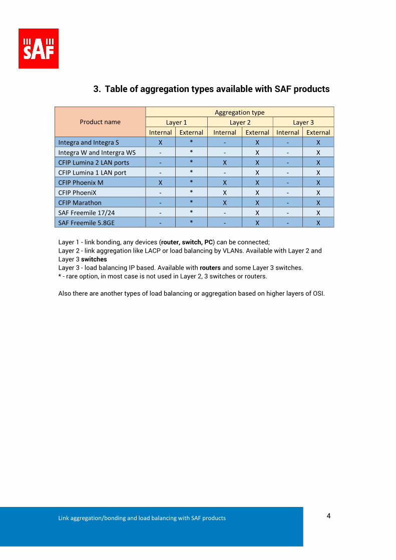
3. Table of aggregation types available with SAF products
Product name
Aggregation type
Layer 1 Layer 2 Layer 3
Internal External Internal External Internal External
Integra and Integra S X * - X - X
Integra W and Intergra WS - * - X - X
CFIP Lumina 2 LAN ports - * X X - X
CFIP Lumina 1 LAN port - * - X - X
CFIP Phoenix M X * X X - X
CFIP PhoeniX - * X X - X
CFIP Marathon - * X X - X
SAF Freemile 17/24 - * - X - X
SAF Freemile 5.8GE - * - X - X
Layer 1 - link bonding, any devices (router, switch, PC) can be connected;
Layer 2 - link aggregation like LACP or load balancing by VLANs. Available with Layer 2 and
Layer 3 switches
Layer 3 - load balancing IP based. Available with routers and some Layer 3 switches.
* - rare option, in most case is not used in Layer 2, 3 switches or routers.
Also there are another types of load balancing or aggregation based on higher layers of OSI.
Link aggregation/bonding and load balancing with SAF products 5
4. Options and considerations for link aggregation
a. Antennas, couplers, OMT, branching system
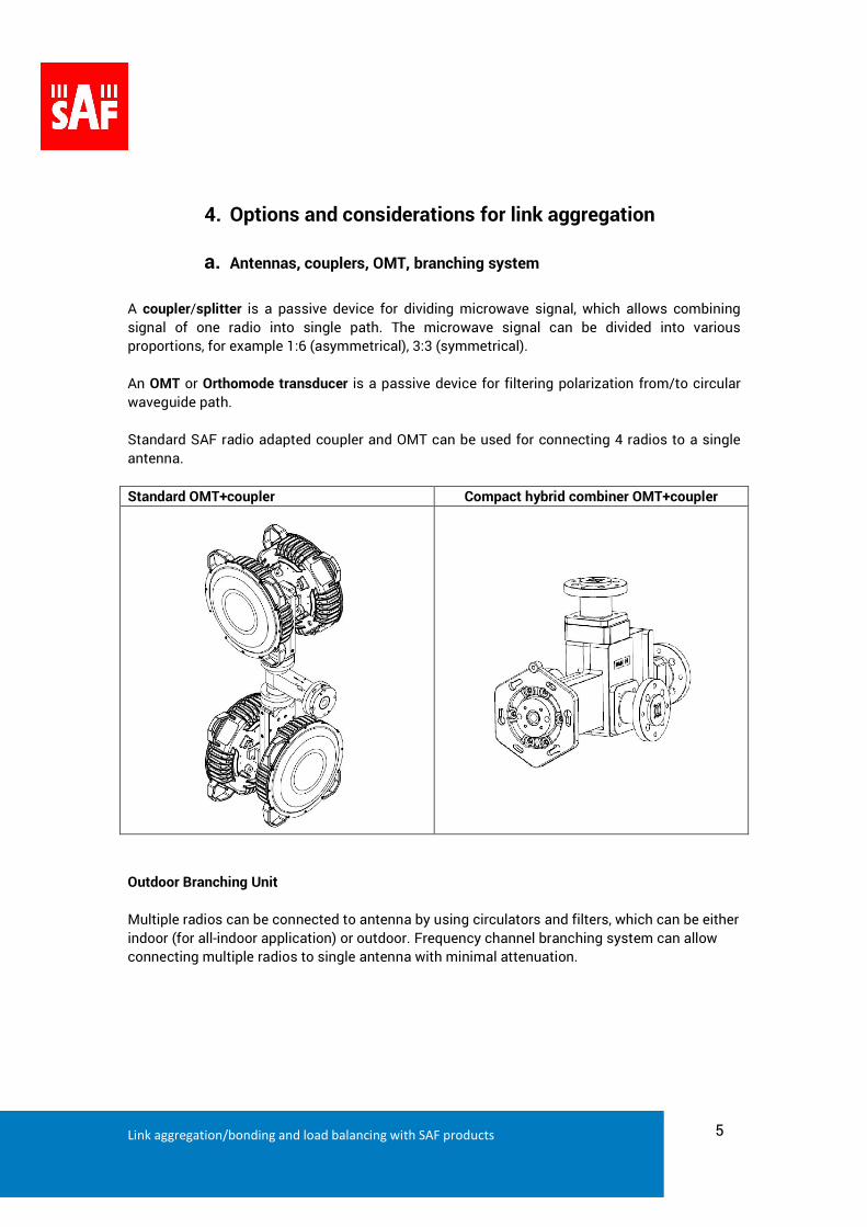
A coupler/splitter is a passive device for dividing microwave signal, which allows combining
signal of one radio into single path. The microwave signal can be divided into various
proportions, for example 1:6 (asymmetrical), 3:3 (symmetrical).
An OMT or Orthomode transducer is a passive device for filtering polarization from/to circular
waveguide path.
Standard SAF radio adapted coupler and OMT can be used for connecting 4 radios to a single
antenna.
Standard OMT+coupler Compact hybrid combiner OMT+coupler
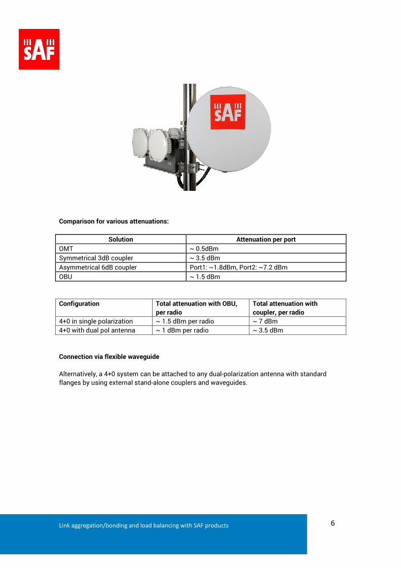
Outdoor Branching Unit
Multiple radios can be connected to antenna by using circulators and filters, which can be either
indoor (for all-indoor application) or outdoor. Frequency channel branching system can allow
connecting multiple radios to single antenna with minimal attenuation.
Link aggregation/bonding and load balancing with SAF products 6
Comparison for various attenuations:
Solution Attenuation per port
OMT ~ 0.5dBm
Symmetrical 3dB coupler ~ 3.5 dBm
Asymmetrical 6dB coupler Port1: ~1.8dBm, Port2: ~7.2 dBm
OBU ~ 1.5 dBm
Configuration Total attenuation with OBU,
per radio
Total attenuation with
coupler, per radio
4+0 in single polarization ~ 1.5 dBm per radio ~ 7 dBm
4+0 with dual pol antenna ~ 1 dBm per radio ~ 3.5 dBm
Connection via flexible waveguide
Alternatively, a 4+0 system can be attached to any dual-polarization antenna with standard
flanges by using external stand-alone couplers and waveguides.
Link aggregation/bonding and load balancing with SAF products 7
b. Capacity and link options
In many cases the target capacity is 1Gbps, which is built from multiple parallel links. Below is a
table for option of achieving close to 1Gbps capacity with CFIP PhoeniX equipment.
Configuration Total capacity Total BW Comment
3+0 at 56MHz 256QAM strong
FEC
3x 334 = 1002 Mbps 168 MHz
4+0 at 56MHz 64QAM strong FEC 4x 241 = 964 Mbps 224 MHz Best system gain for
longer distances or
smaller antennas
4+0 at 40MHz 256QAM weak FEC 4x 248 = 992 Mbps 160 MHz
4+0 at 50MHz 128QAM strong
FEC
4x 249 = 996 Mbps 200 MHz
4+0 at 56MHZ 256QAM weak FEC 4x 360 = 1440 Mbps 224 MHz
With CFIP PhoeniX M system there is possibility to built radio links with mixed payload.
Example capacities with Integra
Configuration Total capacity Total BW Comment
2+0 at 60MHz 1024QAM Integra/Integra-S 2x 474 = 948
Mbps
120MHz
2+0 at 80MHz 256QAM Integra-W/Integra-WS 2x 514 = 1028
Mbps
160MHz Very high system gain
for link budget at
1Gbps
Link aggregation/bonding and load balancing with SAF products 8
5. Built-in configuration examples
5.1 CFIP Lumina:
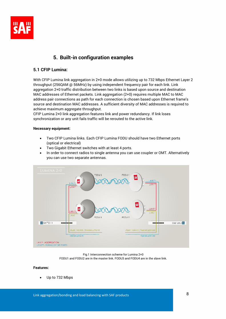
With CFIP Lumina link aggregation in 2+0 mode allows utilizing up to 732 Mbps Ethernet Layer 2
throughput (256QAM @ 56MHz) by using independent frequency pair for each link. Link
aggregation 2+0 traffic distribution between two links is based upon source and destination
MAC addresses of Ethernet packets. Link aggregation (2+0) requires multiple MAC to MAC
address pair connections as path for each connection is chosen based upon Ethernet frame’s
source and destination MAC addresses. A sufficient diversity of MAC addresses is required to
achieve maximum aggregate throughput.
CFIP Lumina 2+0 link aggregation features link and power redundancy. If link loses
synchronization or any unit fails traffic will be rerouted to the active link.
Necessary equipment:
Two CFIP Lumina links. Each CFIP Lumina FODU should have two Ethernet ports
(optical or electrical)
Two Gigabit Ethernet switches with at least 4 ports.
In order to connect radios to single antenna you can use coupler or OMT. Alternatively
you can use two separate antennas.
Fig.1 Interconnection scheme for Lumina 2+0
FODU1 and FODU2 are in the master link. FODU3 and FODU4 are in the slave link.
Features:
Up to 732 Mbps
Link aggregation/bonding and load balancing with SAF products 9
Physical layer protection:
o Protection of hardware failure
o Radio protection
o Modem protection
o Ethernet protection
Automatic reconfiguration to 1+0 (traffic rerouting) in case of:
o Synchronization loss of master link
o Synchronization loss of slave link
o Hardware failure of any CFIP Lumina FODU
o Power supply failure
o Cable failure (link loss)
Average switchover time 100ms
If modulation of one link is downshifted, modulation on other link will be aligned to the same
configuration.
5.2 CFIP PhoeniX:
With CFIP Phoenix built-in link aggregation in 2+0, 3+0 and 4+0 modes allows utilizing up to
1Gbps Ethernet Layer 2 throughput (256QAM @ 56MHz) by using independent frequency pair
for each link. An aggregation method is the same as CFIP Lumina except following:
o Hardware failure of any CFIP PhoeniX IDU
o Power supply failure
o Cable failure (link loss)
Optionally there’s available CFIP PhoeniX IDU with power protection port (P/N S0GIP*11), which
provides redundancy of internal power board, external power supply or power cables.
Necessary equipment:
From four up to eight CFIP Phoenix IDU/ODU pairs.
Two Gigabit Ethernet switches with at least 4 ports.
In order to connect radios to antenna or antennas you can use OMT or/and couplers.
Link aggregation/bonding and load balancing with SAF products 10
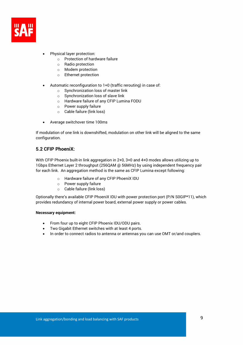
Fig.2 Interconnection scheme for CFIP PhoeniX 2+0
IDU1 and IDU2 are in the master link. IDU3 and IDU4 are in the slave link.
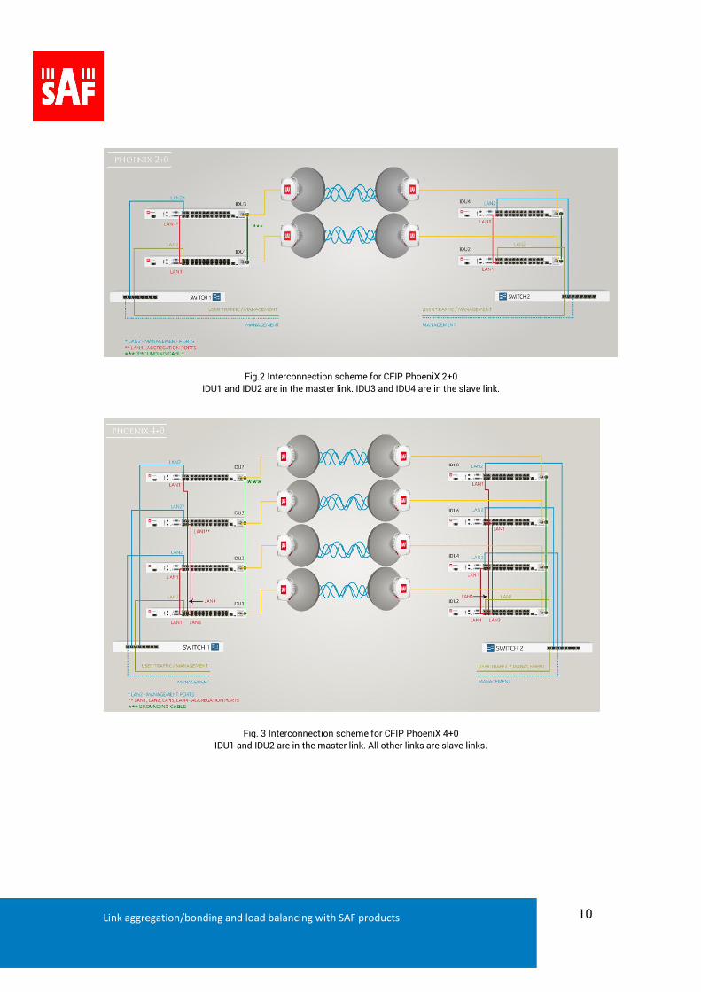
Fig. 3 Interconnection scheme for CFIP PhoeniX 4+0
IDU1 and IDU2 are in the master link. All other links are slave links.
Link aggregation/bonding and load balancing with SAF products 11
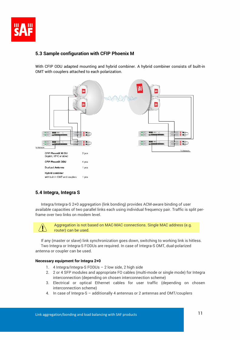
5.3 Sample configuration with CFIP Phoenix M
With CFIP ODU adapted mounting and hybrid combiner. A hybrid combiner consists of built-in
OMT with couplers attached to each polarization.
5.4 Integra, Integra S
Integra/Integra-S 2+0 aggregation (link bonding) provides ACM-aware binding of user
available capacities of two parallel links each using individual frequency pair. Traffic is split per-
frame over two links on modem level.
Aggregation is not based on MAC-MAC connections. Single MAC address (e.g.
router) can be used.
If any (master or slave) link synchronization goes down, switching to working link is hitless.
Two Integra or Integra-S FODUs are required. In case of Integra-S OMT, dual-polarized
antenna or coupler can be used.
Necessary equipment for Integra 2+0
1. 4 Integra/Integra-S FODUs – 2 low side, 2 high side
2. 2 or 4 SFP modules and appropriate FO cables (multi-mode or single mode) for Integra
interconnection (depending on chosen interconnection scheme)
3. Electrical or optical Ethernet cables for user traffic (depending on chosen
interconnection scheme)
4. In case of Integra-S – additionally 4 antennas or 2 antennas and OMT/couplers
Link aggregation/bonding and load balancing with SAF products 12
Interconnection schemes
There are 4 possible interconnection schemes:
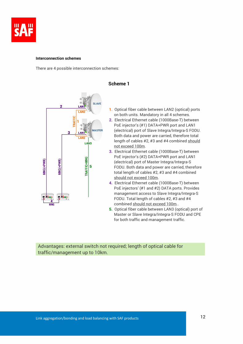
Scheme 1
1. Optical fiber cable between LAN2 (optical) ports
on both units. Mandatory in all 4 schemes.
2. Electrical Ethernet cable (1000Base-T) between
PoE injector’s (#1) DATA+PWR port and LAN1
(electrical) port of Slave Integra/Integra-S FODU.
Both data and power are carried, therefore total
length of cables #2, #3 and #4 combined should
not exceed 100m.
3. Electrical Ethernet cable (1000Base-T) between
PoE injector’s (#2) DATA+PWR port and LAN1
(electrical) port of Master Integra/Integra-S
FODU. Both data and power are carried, therefore
total length of cables #2, #3 and #4 combined
should not exceed 100m.
4. Electrical Ethernet cable (1000Base-T) between
PoE injectors’ (#1 and #2) DATA ports. Provides
management access to Slave Integra/Integra-S
FODU. Total length of cables #2, #3 and #4
combined should not exceed 100m..
5. Optical fiber cable between LAN3 (optical) port of
Master or Slave Integra/Integra-S FODU and CPE
for both traffic and management traffic.
Advantages: external switch not required; length of optical cable for
traffic/management up to 10km.
Link aggregation/bonding and load balancing with SAF products 13
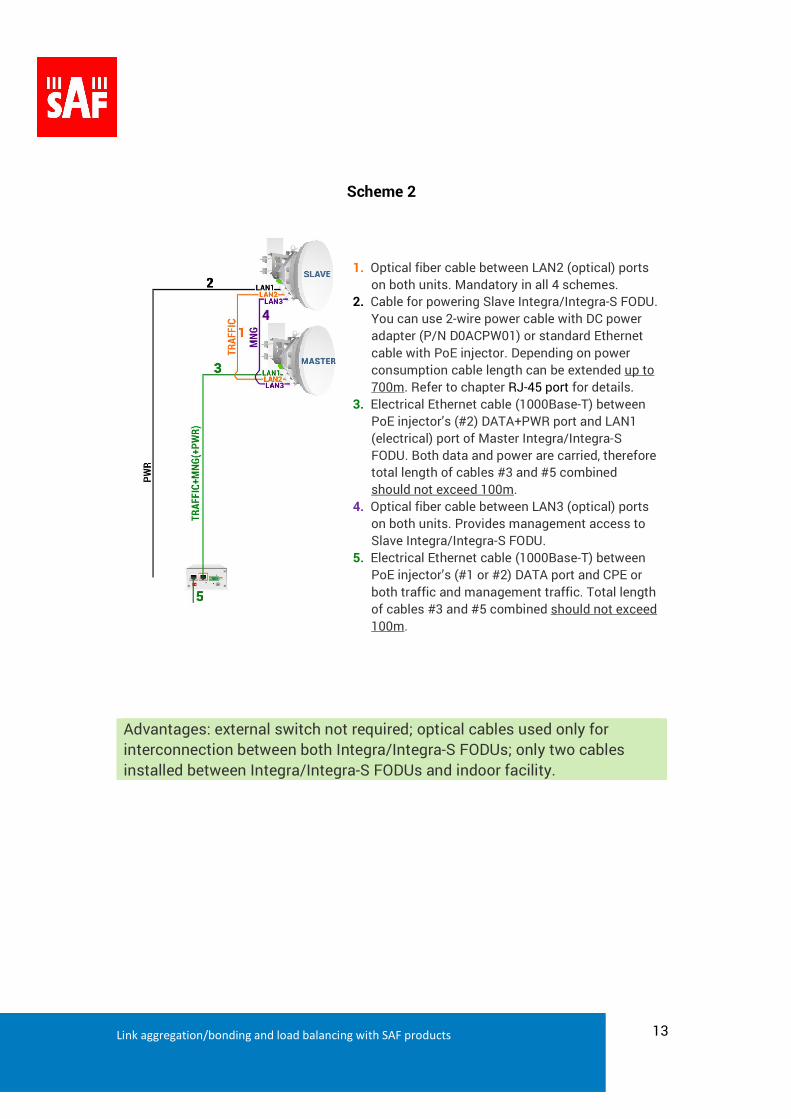
SScheme 2
1. Optical fiber cable between LAN2 (optical) ports
on both units. Mandatory in all 4 schemes.
2. Cable for powering Slave Integra/Integra-S FODU.
You can use 2-wire power cable with DC power
adapter (P/N D0ACPW01) or standard Ethernet
cable with PoE injector. Depending on power
consumption cable length can be extended up to
700m. Refer to chapter RJ-45 port for details.
3. Electrical Ethernet cable (1000Base-T) between
PoE injector’s (#2) DATA+PWR port and LAN1
(electrical) port of Master Integra/Integra-S
FODU. Both data and power are carried, therefore
total length of cables #3 and #5 combined
should not exceed 100m.
4. Optical fiber cable between LAN3 (optical) ports
on both units. Provides management access to
Slave Integra/Integra-S FODU.
5. Electrical Ethernet cable (1000Base-T) between
PoE injector’s (#1 or #2) DATA port and CPE or
both traffic and management traffic. Total length
of cables #3 and #5 combined should not exceed
100m.
Advantages: external switch not required; optical cables used only for
interconnection between both Integra/Integra-S FODUs; only two cables
installed between Integra/Integra-S FODUs and indoor facility.
Link aggregation/bonding and load balancing with SAF products 14
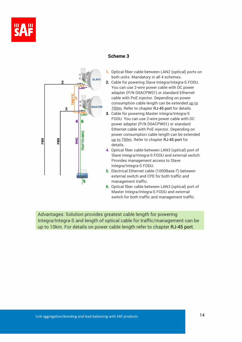
Scheme 3
1. Optical fiber cable between LAN2 (optical) ports on
both units. Mandatory in all 4 schemes.
2. Cable for powering Slave Integra/Integra-S FODU.
You can use 2-wire power cable with DC power
adapter (P/N D0ACPW01) or standard Ethernet
cable with PoE injector. Depending on power
consumption cable length can be extended up to
700m. Refer to chapter RJ-45 port for details.
3. Cable for powering Master Integra/Integra-S
FODU. You can use 2-wire power cable with DC
power adapter (P/N D0ACPW01) or standard
Ethernet cable with PoE injector. Depending on
power consumption cable length can be extended
up to 700m. Refer to chapter RJ-45 port for
details.
4. Optical fiber cable between LAN3 (optical) port of
Slave Integra/Integra-S FODU and external switch.
Provides management access to Slave
Integra/Integra-S FODU.
5. Electrical Ethernet cable (1000Base-T) between
external switch and CPE for both traffic and
management traffic.
6. Optical fiber cable between LAN3 (optical) port of
Master Integra/Integra-S FODU and external
switch for both traffic and management traffic.
Advantages: Solution provides greatest cable length for powering
Integra/Integra-S and length of optical cable for traffic/management can be
up to 10km. For details on power cable length refer to chapter RJ-45 port.
Link aggregation/bonding and load balancing with SAF products 15
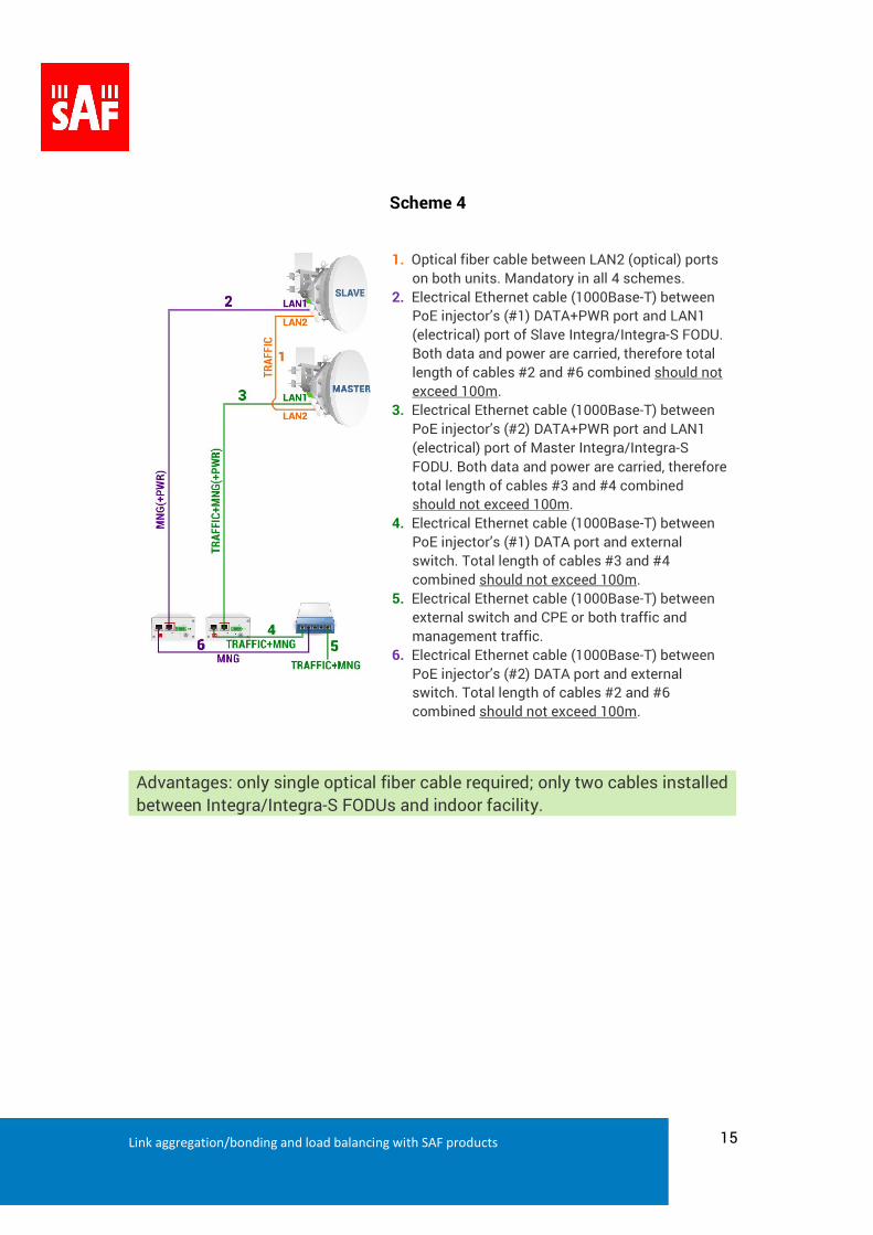
Scheme 4
1. Optical fiber cable between LAN2 (optical) ports
on both units. Mandatory in all 4 schemes.
2. Electrical Ethernet cable (1000Base-T) between
PoE injector’s (#1) DATA+PWR port and LAN1
(electrical) port of Slave Integra/Integra-S FODU.
Both data and power are carried, therefore total
length of cables #2 and #6 combined should not
exceed 100m.
3. Electrical Ethernet cable (1000Base-T) between
PoE injector’s (#2) DATA+PWR port and LAN1
(electrical) port of Master Integra/Integra-S
FODU. Both data and power are carried, therefore
total length of cables #3 and #4 combined
should not exceed 100m.
4. Electrical Ethernet cable (1000Base-T) between
PoE injector’s (#1) DATA port and external
switch. Total length of cables #3 and #4
combined should not exceed 100m.
5. Electrical Ethernet cable (1000Base-T) between
external switch and CPE or both traffic and
management traffic.
6. Electrical Ethernet cable (1000Base-T) between
PoE injector’s (#2) DATA port and external
switch. Total length of cables #2 and #6
combined should not exceed 100m.
Advantages: only single optical fiber cable required; only two cables installed
between Integra/Integra-S FODUs and indoor facility.
Link aggregation/bonding and load balancing with SAF products 16
6. Link aggregation using external equipment
Some network operators would like to use own link aggregation methods based on LACP and
other methods. Most frequently ignored issue is related to putting CFIP management inside one
of two balanced Ethernet paths. This is violation because balancing logic does not expect any
Ethernet device in-between two aggregated switches. As a result traffic will go through but
management access to each CFIP Lumina will be available only from 50% of MAC addresses –
might be available from one PC but not available from another and it is absolutely not
predictable.
We would like to explain some examples showing how to implement link aggregation or load
balance using external switches and routers and ensure stable management access to CFIP
products.
6.1 Link aggregation using external switches via LACP (or PAgP) protocol with
MAC or IP address hashing on CISCO switches.
After switch CRC hash calculation based on chosen method SA-DA, SA or DA switch will send
packet using one or other path. Along with traffic CFIP management packet can be routed to
other branch where requested CFIP unit doesn’t exist and this may cause inaccessibility of CFIP
management. To avoid this problem we recommend using two port CFIP Lumina or CFIP
PhoeniX where you can separate data traffic from management traffic using VLANs.
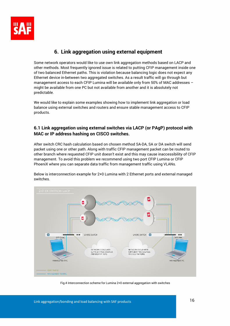
Below is interconnection example for 2+0 Lumina with 2 Ethernet ports and external managed
switches.
Fig.4 Interconnection scheme for Lumina 2+0 external aggregation with switches
Link aggregation/bonding and load balancing with SAF products 17
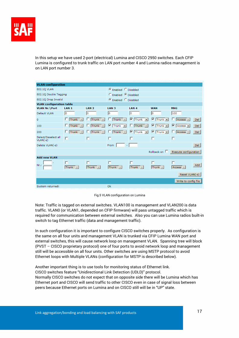
In this setup we have used 2-port (electrical) Lumina and CISCO 2950 switches. Each CFIP
Lumina is configured to trunk traffic on LAN port number 4 and Lumina radios management is
on LAN port number 3.
Fig.5 VLAN configuration on Lumina
Note: Traffic is tagged on external switches. VLAN100 is management and VLAN200 is data
traffic. VLAN0 (or VLAN1, depended on CFIP firmware) will pass untagged traffic which is
required for communication between external switches. Also you can use Lumina radios built-in
switch to tag Ethernet traffic (data and management traffic).
In such configuration it is important to configure CISCO switches properly. As configuration is
the same on all four units and management VLAN is trunked via CFIP Lumina WAN port and
external switches, this will cause network loop on management VLAN. Spanning tree will block
(PVST – CISCO proprietary protocol) one of four ports to avoid network loop and management
still will be accessible on all four units. Other switches are using MSTP protocol to avoid
Ethernet loops with Multiple VLANs (configuration for MSTP is described below).
Another important thing is to use tools for monitoring status of Ethernet link.
CISCO switches feature “Unidirectional Link Detection (UDLD)” protocol.
Normally CISCO switches do not expect that on opposite side there will be Lumina which has
Ethernet port and CISCO will send traffic to other CISCO even in case of signal loss between
peers because Ethernet ports on Lumina and on CISCO still will be in “UP” state.
Link aggregation/bonding and load balancing with SAF products 18
UDLD can detect broken link even if Ethernet port is “UP”, shut down it and all traffic will be
redirected to another branch. Aggregation restoring is more or less depended on external
switches in case of radio sync loss.
UDLD is disabled by default. You can configure it globally or on specific interface.
In our configuration we have enabled UDLD globally.
CFIP Lumina, Marathon and PhoeniX products have “Link State Propagation” feature which can
shutdown the Ethernet port in case of sync loss.
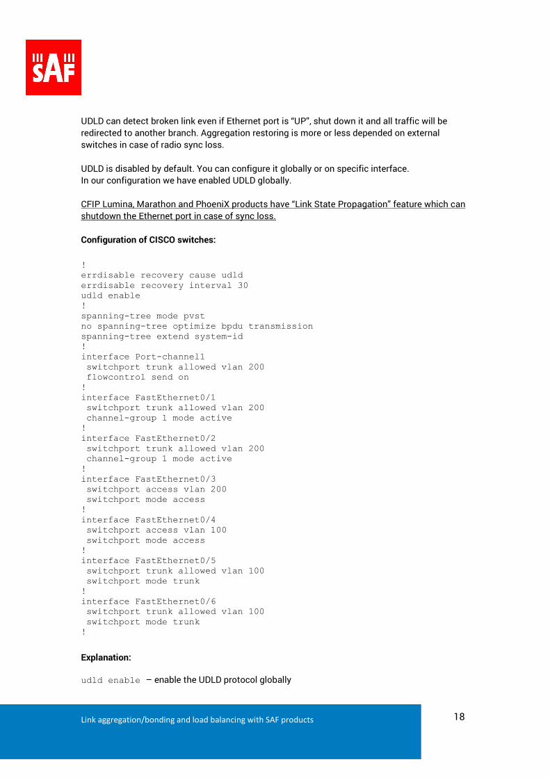
Configuration of CISCO switches:
! errdisable recovery cause udld errdisable recovery interval 30 udld enable ! spanning-tree mode pvst no spanning-tree optimize bpdu transmission spanning-tree extend system-id ! interface Port-channel1 switchport trunk allowed vlan 200 flowcontrol send on ! interface FastEthernet0/1 switchport trunk allowed vlan 200 channel-group 1 mode active ! interface FastEthernet0/2 switchport trunk allowed vlan 200 channel-group 1 mode active ! interface FastEthernet0/3 switchport access vlan 200 switchport mode access ! interface FastEthernet0/4 switchport access vlan 100 switchport mode access ! interface FastEthernet0/5 switchport trunk allowed vlan 100 switchport mode trunk ! interface FastEthernet0/6 switchport trunk allowed vlan 100 switchport mode trunk !
Explanation:
udld enable – enable the UDLD protocol globally
Link aggregation/bonding and load balancing with SAF products 19
errdisable recovery cause udld – enable the timer to automatically recover from the UDLD error-
disabled state
errdisable recovery interval 30 – the recovery time interval to bring the interface out of the error-
disabled. 30 seconds is minimal number.
interface Port-channel1 – Specifies EtherChannel number
Interfaces Fa0/1 - 0/2 are used to trunk aggregated traffic to other peer thru Lumina radios.
Interface Fa0/3 – is network cloud (lots of SA-DA MACs)
Interface Fa0/4 – is for management PC
Interfaces Fa0/5 – 0/6 are used to trunk management data to Lumina.
There is no limitation to number of aggregated parallel links it depends on opportunity of
external switches.
The same configuration of Lumina radios and switches will be in case of link aggregation based
on IP hashing. You need to add “port-channel load-balance src-dst-ip” in to CISCO global
configuration.
6.2 Link aggregation using external switches via LACP protocol with MSTP
enabled on external switch.
By default CISCO switches are using proprietary PVST protocol. This protocol works very well
without special “fine tuning” of STP. Other brands have MSTP (Multiple Spanning-Tree protocol)
protocol which requires “fine tune” for correct STP behavior.
Important peculiar properties are: you need to setup region name and revision, instances per
VLAN, BPDU filter must be applied on aggregated port (not physical interface), correct port
priority and path costs for aggregated ports.
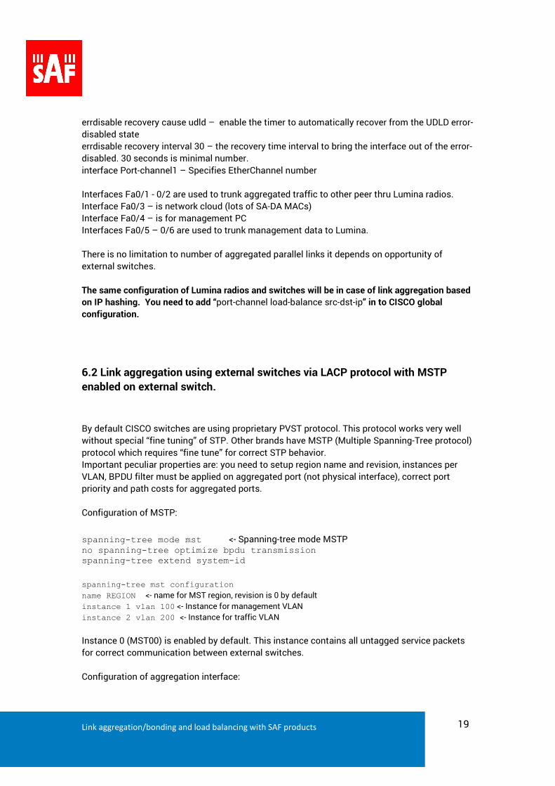
Configuration of MSTP:
spanning-tree mode mst <- Spanning-tree mode MSTP no spanning-tree optimize bpdu transmission spanning-tree extend system-id
spanning-tree mst configuration
name REGION <- name for MST region, revision is 0 by default
instance 1 vlan 100 <- Instance for management VLAN
instance 2 vlan 200 <- Instance for traffic VLAN
Instance 0 (MST00) is enabled by default. This instance contains all untagged service packets
for correct communication between external switches.
Configuration of aggregation interface:
Link aggregation/bonding and load balancing with SAF products 20
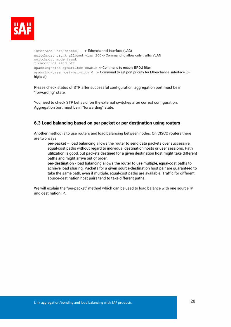
interface Port-channel1 <- Etherchannel interface (LAG)
switchport trunk allowed vlan 200 <- Command to allow only traffic VLAN switchport mode trunk flowcontrol send off
spanning-tree bpdufilter enable <- Command to enable BPDU filter
spanning-tree port-priority 0 <- Command to set port priority for Etherchannel interface (0 -
highest)
Please check status of STP after successful configuration, aggregation port must be in
“forwarding” state.
You need to check STP behavior on the external switches after correct configuration.
Aggregation port must be in “forwarding” state.
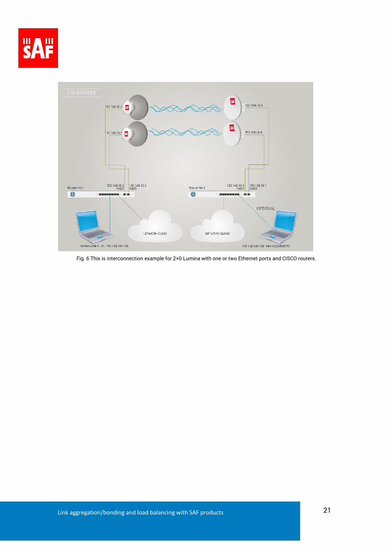
6.3 Load balancing based on per packet or per destination using routers
Another method is to use routers and load balancing between nodes. On CISCO routers there
are two ways:
per-packet – load balancing allows the router to send data packets over successive
equal-cost paths without regard to individual destination hosts or user sessions. Path
utilization is good, but packets destined for a given destination host might take different
paths and might arrive out of order.
per-destination - load balancing allows the router to use multiple, equal-cost paths to
achieve load sharing. Packets for a given source-destination host pair are guaranteed to
take the same path, even if multiple, equal-cost paths are available. Traffic for different
source-destination host pairs tend to take different paths.
We will explain the “per-packet” method which can be used to load balance with one source IP
and destination IP.
Link aggregation/bonding and load balancing with SAF products 21
Fig. 6 This is interconnection example for 2+0 Lumina with one or two Ethernet ports and CISCO routers.
Link aggregation/bonding and load balancing with SAF products 22
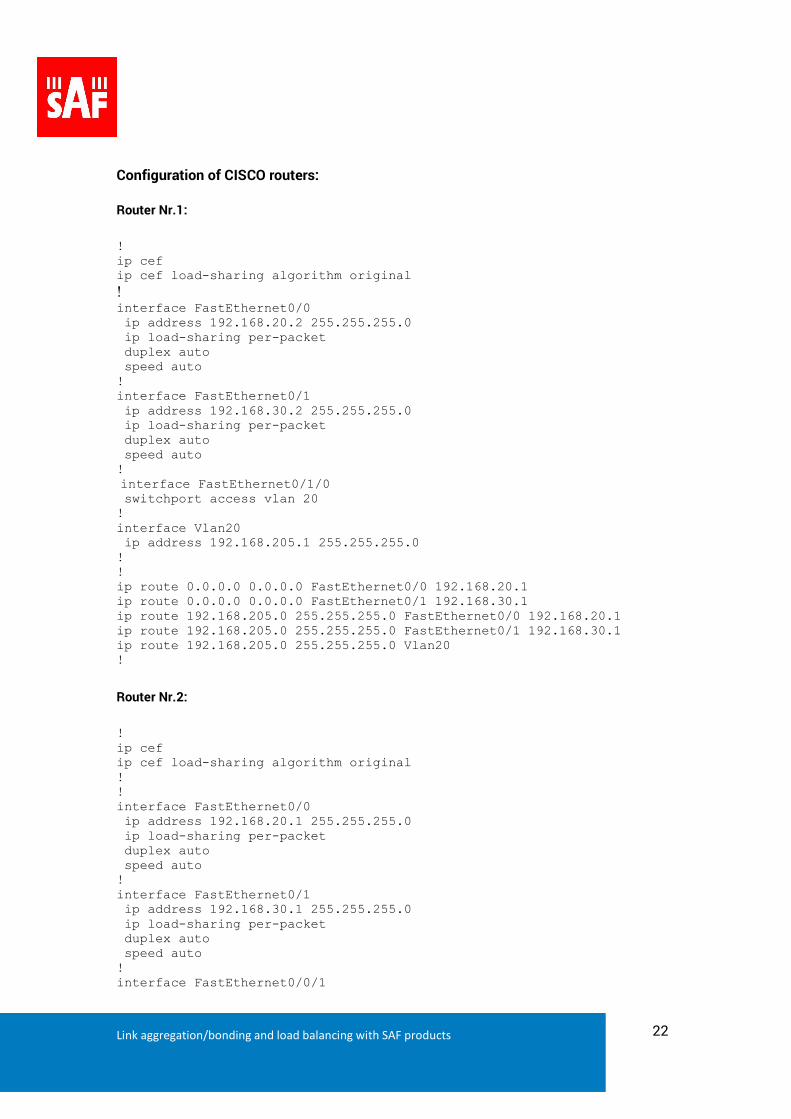
Configuration of CISCO routers:
Router Nr.1:
! ip cef ip cef load-sharing algorithm original ! interface FastEthernet0/0 ip address 192.168.20.2 255.255.255.0 ip load-sharing per-packet duplex auto speed auto ! interface FastEthernet0/1 ip address 192.168.30.2 255.255.255.0 ip load-sharing per-packet duplex auto speed auto ! interface FastEthernet0/1/0 switchport access vlan 20 ! interface Vlan20 ip address 192.168.205.1 255.255.255.0 ! ! ip route 0.0.0.0 0.0.0.0 FastEthernet0/0 192.168.20.1 ip route 0.0.0.0 0.0.0.0 FastEthernet0/1 192.168.30.1 ip route 192.168.205.0 255.255.255.0 FastEthernet0/0 192.168.20.1 ip route 192.168.205.0 255.255.255.0 FastEthernet0/1 192.168.30.1 ip route 192.168.205.0 255.255.255.0 Vlan20 !
Router Nr.2:
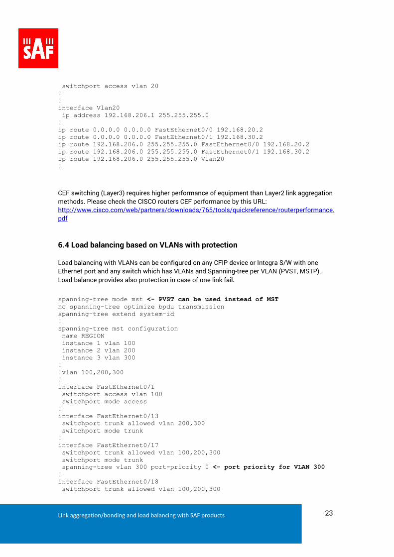
! ip cef ip cef load-sharing algorithm original ! ! interface FastEthernet0/0 ip address 192.168.20.1 255.255.255.0 ip load-sharing per-packet duplex auto speed auto ! interface FastEthernet0/1 ip address 192.168.30.1 255.255.255.0 ip load-sharing per-packet duplex auto speed auto ! interface FastEthernet0/0/1
Link aggregation/bonding and load balancing with SAF products 23
switchport access vlan 20 ! ! interface Vlan20 ip address 192.168.206.1 255.255.255.0 ! ip route 0.0.0.0 0.0.0.0 FastEthernet0/0 192.168.20.2 ip route 0.0.0.0 0.0.0.0 FastEthernet0/1 192.168.30.2 ip route 192.168.206.0 255.255.255.0 FastEthernet0/0 192.168.20.2 ip route 192.168.206.0 255.255.255.0 FastEthernet0/1 192.168.30.2 ip route 192.168.206.0 255.255.255.0 Vlan20 !
CEF switching (Layer3) requires higher performance of equipment than Layer2 link aggregation
methods. Please check the CISCO routers CEF performance by this URL:
http://www.cisco.com/web/partners/downloads/765/tools/quickreference/routerperformance.
6.4 Load balancing based on VLANs with protection
Load balancing with VLANs can be configured on any CFIP device or Integra S/W with one
Ethernet port and any switch which has VLANs and Spanning-tree per VLAN (PVST, MSTP).
Load balance provides also protection in case of one link fail.
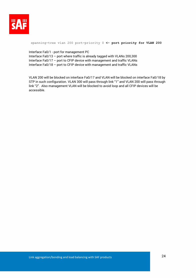
spanning-tree mode mst <- PVST can be used instead of MST no spanning-tree optimize bpdu transmission spanning-tree extend system-id ! spanning-tree mst configuration name REGION instance 1 vlan 100 instance 2 vlan 200 instance 3 vlan 300 ! !vlan 100,200,300 ! interface FastEthernet0/1 switchport access vlan 100 switchport mode access ! interface FastEthernet0/13 switchport trunk allowed vlan 200,300 switchport mode trunk ! interface FastEthernet0/17 switchport trunk allowed vlan 100,200,300 switchport mode trunk spanning-tree vlan 300 port-priority 0 <- port priority for VLAN 300 ! interface FastEthernet0/18 switchport trunk allowed vlan 100,200,300
Link aggregation/bonding and load balancing with SAF products 24
spanning-tree vlan 200 port-priority 0 <- port priority for VLAN 200
Interface Fa0/1 - port for management PC
Interface Fa0/13 – port where traffic is already tagged with VLANs 200,300
Interface Fa0/17 – port to CFIP device with management and traffic VLANs
Interface Fa0/18 – port to CFIP device with management and traffic VLANs
VLAN 200 will be blocked on interface Fa0/17 and VLAN will be blocked on interface Fa0/18 by
STP in such configuration. VLAN 300 will pass through link “1” and VLAN 200 will pass through
link “2”. Also management VLAN will be blocked to avoid loop and all CFIP devices will be
accessible.
Link aggregation/bonding and load balancing with SAF products 25
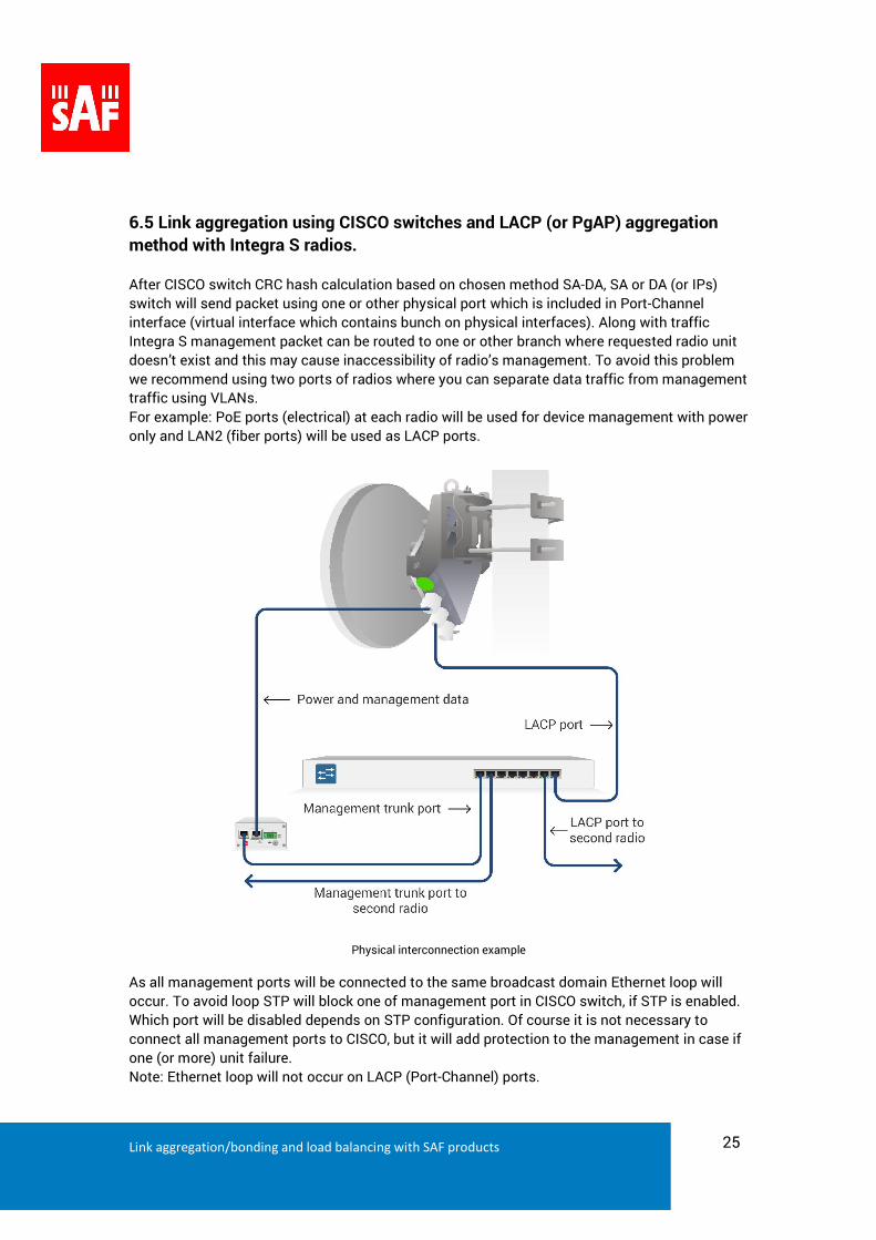
6.5 Link aggregation using CISCO switches and LACP (or PgAP) aggregation
method with Integra S radios.
After CISCO switch CRC hash calculation based on chosen method SA-DA, SA or DA (or IPs)
switch will send packet using one or other physical port which is included in Port-Channel
interface (virtual interface which contains bunch on physical interfaces). Along with traffic
Integra S management packet can be routed to one or other branch where requested radio unit
doesn’t exist and this may cause inaccessibility of radio’s management. To avoid this problem
we recommend using two ports of radios where you can separate data traffic from management
traffic using VLANs.
For example: PoE ports (electrical) at each radio will be used for device management with power
only and LAN2 (fiber ports) will be used as LACP ports.
Physical interconnection example
As all management ports will be connected to the same broadcast domain Ethernet loop will
occur. To avoid loop STP will block one of management port in CISCO switch, if STP is enabled.
Which port will be disabled depends on STP configuration. Of course it is not necessary to
connect all management ports to CISCO, but it will add protection to the management in case if
one (or more) unit failure.
Note: Ethernet loop will not occur on LACP (Port-Channel) ports.
Link aggregation/bonding and load balancing with SAF products 26
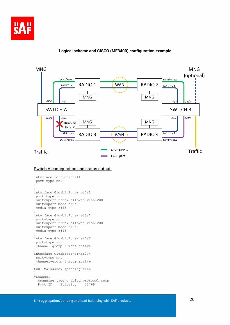
Logical scheme and CISCO (ME3400) configuration example
Swtich A configuration and status output: interface Port-channel1 port-type nni ! ! interface GigabitEthernet0/1 port-type nni switchport trunk allowed vlan 200 switchport mode trunk media-type rj45 ! interface GigabitEthernet0/2 port-type nni switchport trunk allowed vlan 200 switchport mode trunk media-type rj45 ! interface GigabitEthernet0/3 port-type nni channel-group 1 mode active ! interface GigabitEthernet0/4 port-type nni channel-group 1 mode active ! tw01-Main#show spanning-tree VLAN0001 Spanning tree enabled protocol rstp Root ID Priority 32769
Link aggregation/bonding and load balancing with SAF products 27
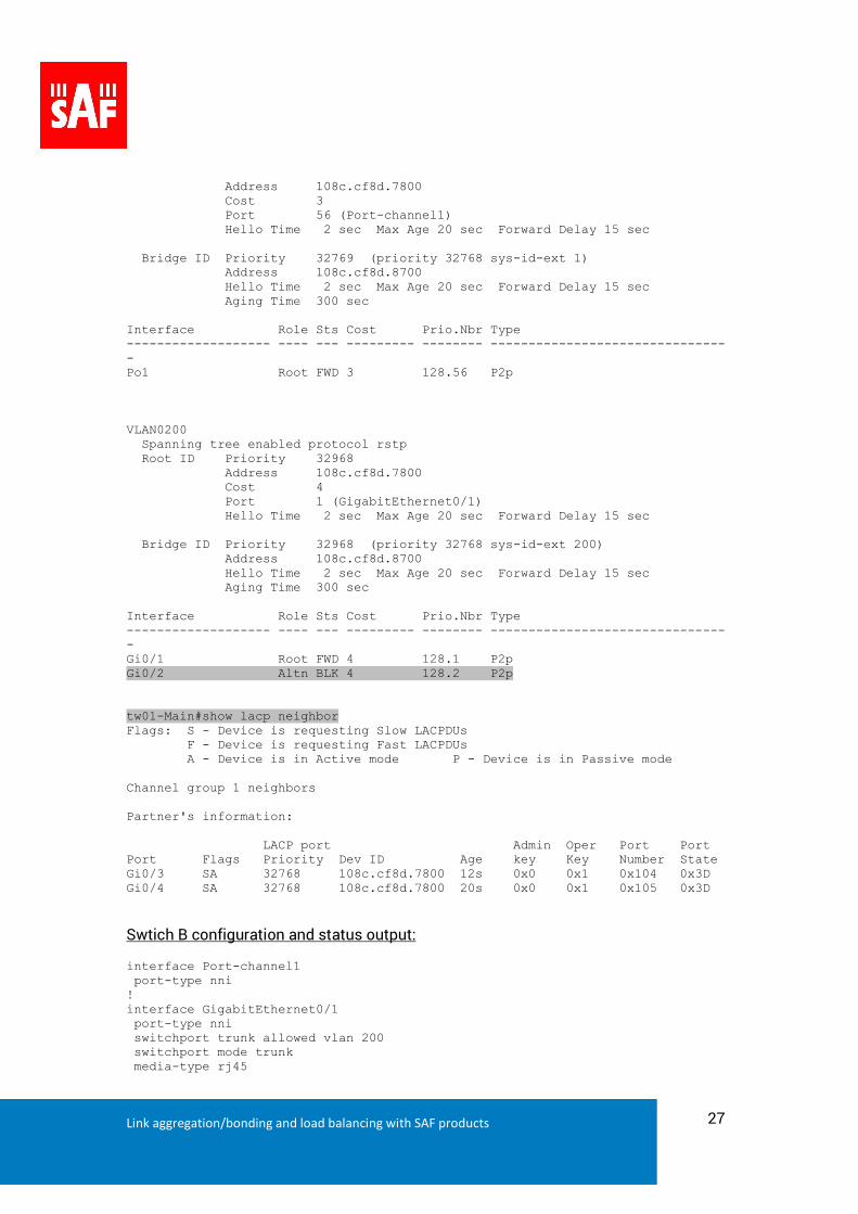
Address 108c.cf8d.7800 Cost 3 Port 56 (Port-channel1) Hello Time 2 sec Max Age 20 sec Forward Delay 15 sec Bridge ID Priority 32769 (priority 32768 sys-id-ext 1) Address 108c.cf8d.8700 Hello Time 2 sec Max Age 20 sec Forward Delay 15 sec Aging Time 300 sec Interface Role Sts Cost Prio.Nbr Type ------------------- ---- --- --------- -------- -------------------------------- Po1 Root FWD 3 128.56 P2p VLAN0200 Spanning tree enabled protocol rstp Root ID Priority 32968 Address 108c.cf8d.7800 Cost 4 Port 1 (GigabitEthernet0/1) Hello Time 2 sec Max Age 20 sec Forward Delay 15 sec Bridge ID Priority 32968 (priority 32768 sys-id-ext 200) Address 108c.cf8d.8700 Hello Time 2 sec Max Age 20 sec Forward Delay 15 sec Aging Time 300 sec Interface Role Sts Cost Prio.Nbr Type ------------------- ---- --- --------- -------- -------------------------------- Gi0/1 Root FWD 4 128.1 P2p Gi0/2 Altn BLK 4 128.2 P2p tw01-Main#show lacp neighbor Flags: S - Device is requesting Slow LACPDUs F - Device is requesting Fast LACPDUs A - Device is in Active mode P - Device is in Passive mode Channel group 1 neighbors Partner's information: LACP port Admin Oper Port Port Port Flags Priority Dev ID Age key Key Number State Gi0/3 SA 32768 108c.cf8d.7800 12s 0x0 0x1 0x104 0x3D Gi0/4 SA 32768 108c.cf8d.7800 20s 0x0 0x1 0x105 0x3D
Swtich B configuration and status output: interface Port-channel1 port-type nni ! interface GigabitEthernet0/1 port-type nni switchport trunk allowed vlan 200 switchport mode trunk media-type rj45

Link aggregation/bonding and load balancing with SAF products 28
! interface GigabitEthernet0/2 port-type nni switchport trunk allowed vlan 200 switchport mode trunk media-type rj45 ! interface GigabitEthernet0/3 port-type nni channel-group 1 mode active ! interface GigabitEthernet0/4 port-type nni channel-group 1 mode active ! tw3-main#show lacp neighbor Flags: S - Device is requesting Slow LACPDUs F - Device is requesting Fast LACPDUs A - Device is in Active mode P - Device is in Passive mode Channel group 1 neighbors Partner's information: LACP port Admin Oper Port Port Port Flags Priority Dev ID Age key Key Number State Gi0/3 SA 32768 108c.cf8d.8700 10s 0x0 0x1 0x104 0x3D Gi0/4 SA 32768 108c.cf8d.8700 7s 0x0 0x1 0x105 0x3D tw3-main#show spanning-tree VLAN0001 Spanning tree enabled protocol rstp Root ID Priority 32769 Address 108c.cf8d.7800 This bridge is the root Hello Time 2 sec Max Age 20 sec Forward Delay 15 sec Bridge ID Priority 32769 (priority 32768 sys-id-ext 1) Address 108c.cf8d.7800 Hello Time 2 sec Max Age 20 sec Forward Delay 15 sec Aging Time 300 sec Interface Role Sts Cost Prio.Nbr Type ------------------- ---- --- --------- -------- -------------------------------- Po1 Desg FWD 3 128.56 P2p VLAN0200 Spanning tree enabled protocol rstp Root ID Priority 32968 Address 108c.cf8d.7800 This bridge is the root Hello Time 2 sec Max Age 20 sec Forward Delay 15 sec Bridge ID Priority 32968 (priority 32768 sys-id-ext 200) Address 108c.cf8d.7800 Hello Time 2 sec Max Age 20 sec Forward Delay 15 sec Aging Time 300 sec
Link aggregation/bonding and load balancing with SAF products 29
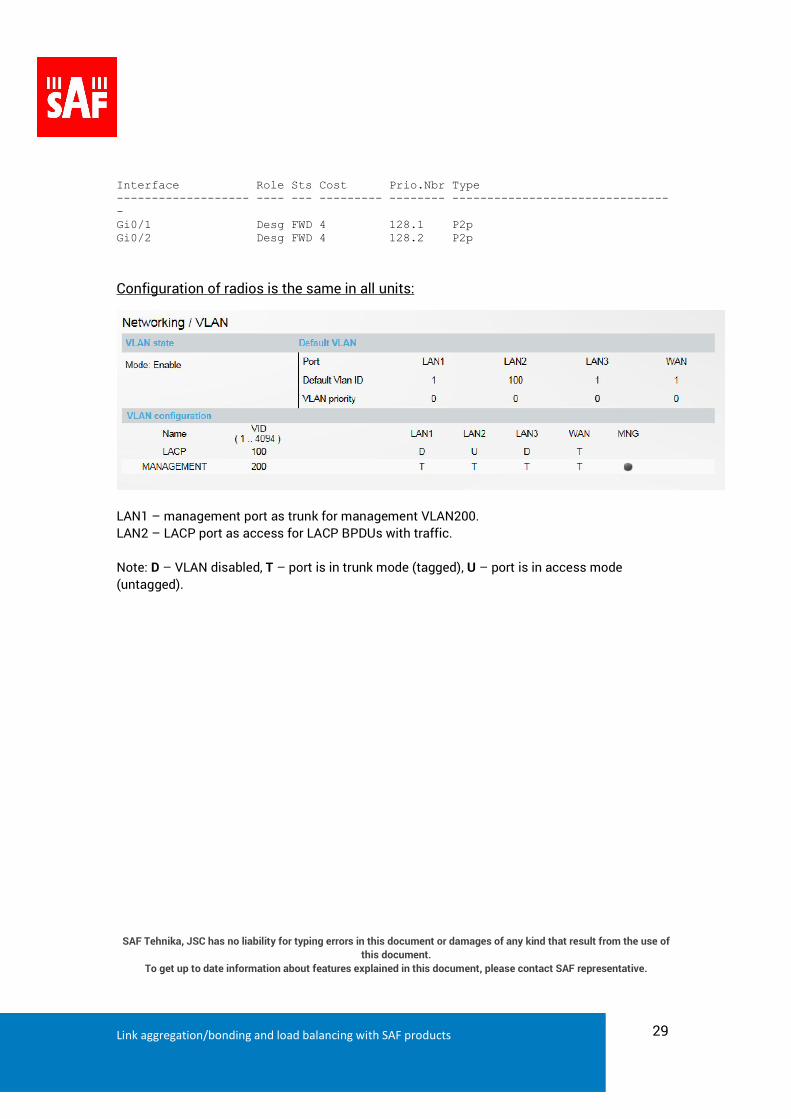
Interface Role Sts Cost Prio.Nbr Type ------------------- ---- --- --------- -------- -------------------------------- Gi0/1 Desg FWD 4 128.1 P2p Gi0/2 Desg FWD 4 128.2 P2p
Configuration of radios is the same in all units:
LAN1 – management port as trunk for management VLAN200.
LAN2 – LACP port as access for LACP BPDUs with traffic.
Note: D – VLAN disabled, T – port is in trunk mode (tagged), U – port is in access mode
(untagged).
SAF Tehnika, JSC has no liability for typing errors in this document or damages of any kind that result from the use of
this document.
To get up to date information about features explained in this document, please contact SAF representative.