Embed Size (px)
Citation preview

SIGALARM
MODEL 210
MICROGUARD RCI 534 Upgrade
Installation and Calibration Manual


MicroGuard RCI 534 Upgrade Installation and Calibration Manual
SkyAzúl, Equipment Solutions www.skyazul.com 301-371-6126
NOTICE
SkyAzúl makes no warranty of any kind with regard to this material, including, but not limited to, the implied warranties of merchantability and/or its fitness for a particular purpose.
SkyAzúl will not be liable for errors contained in this manual or for incidental or consequential damages in connection with the furnishing, performance, or use of this manual. This document contains proprietary information, which is protected by copyright, and all rights are reserved.
No part of this document may be photocopied, reproduced, or translated to another language without the prior written consent of SkyAzúl.
SkyAzúl reserves proprietary rights to all drawings, photos and the data contained therein. The drawings, photos and data are confidential and cannot be used or reproduced without the written consent of SkyAzúl. The drawings and/or photos are subject to technical modification without prior notice.
All information in this document is subject to change without notice.
REV DATE NAME DESCRIPTION
- 04/23/14 SC RCI 534 Upgrade - Installation and Calibration Manual
SkyAzúl, Inc. 14 Walnut Street Middletown, MD 21769 Fax 301-371-0029 [email protected]


MicroGuard RCI 534 Upgrade Installation and Calibration Manual
SkyAzúl, Equipment Solutions www.skyazul.com 301-371-6126
TABLE OF CONTENTS Chapter 1 - Installation Introduction System Information Upgrade Parts
Computer Assembly RCI 534 Display Module Reeling Drum
Computer Wiring Units with Swing Switches Removal and Installation
Chapter 2 – Calibration
Introduction Required Tools Number Conversion Number Entry The Display Calibration Mode
Menu 00 – Error Codes Group “A” Fault Codes Group “B” Fault Codes Group “C” Fault Codes Group “D” Fault Codes
Menu 01 – Crane Data Menu 02 – Zero Sensor
Boom Extension Sensor Zero Boom Angle Sensor Zero
Menu 03 – Span Boom Angle Sensor Boom Extension Sensor
Menu 04 – Swing Pot Zero Swing Pot Zero Swing Pot Direction
Menu 05 – Main Boom Radius/Moment First Length Second Length Third Length
Menu 06 – Boom Deflection Correction Menu 07 – Head Angle Menu 08 – Attachments Menu 09 – Winches Menu 10 – Rope Limits Menu 11 – Alarms Menu 12 – Digital Inputs Menu 13 – Monitor Menu 15 – Pressure Appendix A – Glossary of Terms
1 1 2 2 2 2 3 5 6 A M
9 9 9
10 11 12 14 15 17 18 19 20 22 22 23 25 25 26 28 28 29 30 31 33 35 38 40 43 45 47 49 51 52 53 54

38 Menu 07 – Head Angle 40 Menu 08 – Attachments 43 Menu 09 – Winches 45 Menu 10 – Rope Limits 47
Menu 12 – Digital Inputs 51 Menu 13 – Monitor 52 Menu 15 – Pressure 53 Appendix A – Glossary of Terms 54

CHAPTER 1 - INSTALLATION Introduction - This chapter will cover information necessary for installing the MicroGuard 534 system.
Please read the Operator’s Manual carefully before operating the system. The system installer must be knowledgeable in safety guidelines, crane capacity information, and the crane manufacturer’s specifications.
For questions about Installation, please contact Technical Support:
SkyAzúl16 Walnut StreetMiddletown, MD 21769 Telephone: (301) 371-6126Fax: (301) [email protected]
1.1 System Information When installing the new computer and display system, Greer Company recommends the existing rectangular shaped reeling drum be replaced with our current production reeling drum, A240690. The rectangular shaped reeling drum has been classed obsolete. There is no longer field support for this product.
Upgrading the reeling drum will ensure you have both field support and parts support in the future. The A240690 Reeling Drum is equipped with mounting brackets and electrical fittings to be a direct replacement for the obsolete part.
The new computer uses Flash RAM technology for loading the Duty Files. If known at the time of purchase, the proper Duty File will be loaded on your computer before installation.
If you are unfamiliar with preparing the computer for use, kit K758743 is available from Greer Company. The kit contains a programming cable and a CD with software, drivers, and the “Greer Mini Loader” program.
MicroGuard RCI 534 Upgrade Installation and Calibration Manual
SkyAzúl, Equipment Solutions www.skyazul.com
1
301-371-6126
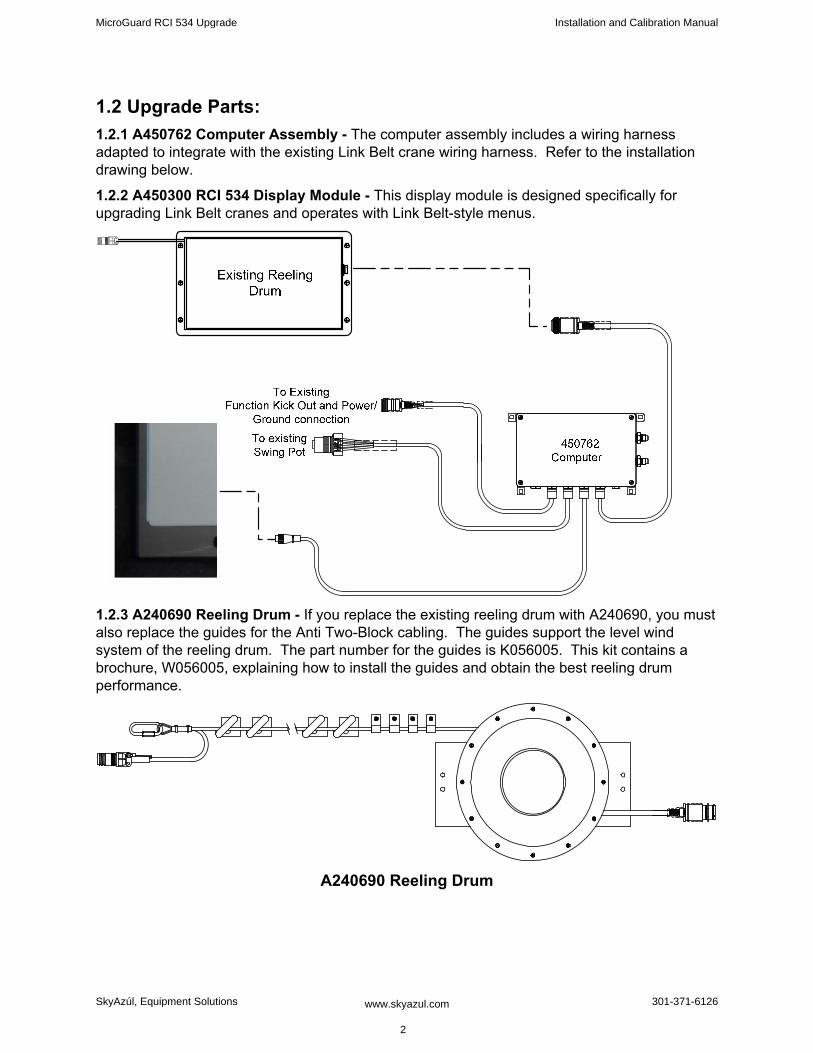
1.2 Upgrade Parts: 1.2.1 A450762 Computer Assembly - The computer assembly includes a wiring harness adapted to integrate with the existing Link Belt crane wiring harness. Refer to the installation drawing below.
1.2.2 A450300 RCI 534 Display Module - This display module is designed specifically for upgrading Link Belt cranes and operates with Link Belt-style menus.
1.2.3 A240690 Reeling Drum - If you replace the existing reeling drum with A240690, you must also replace the guides for the Anti Two-Block cabling. The guides support the level wind system of the reeling drum. The part number for the guides is K056005. This kit contains a brochure, W056005, explaining how to install the guides and obtain the best reeling drum performance.
A240690 Reeling Drum
MicroGuard RCI 534 Upgrade Installation and Calibration Manual
SkyAzúl, Equipment Solutions www.skyazul.com 2
301-371-6126
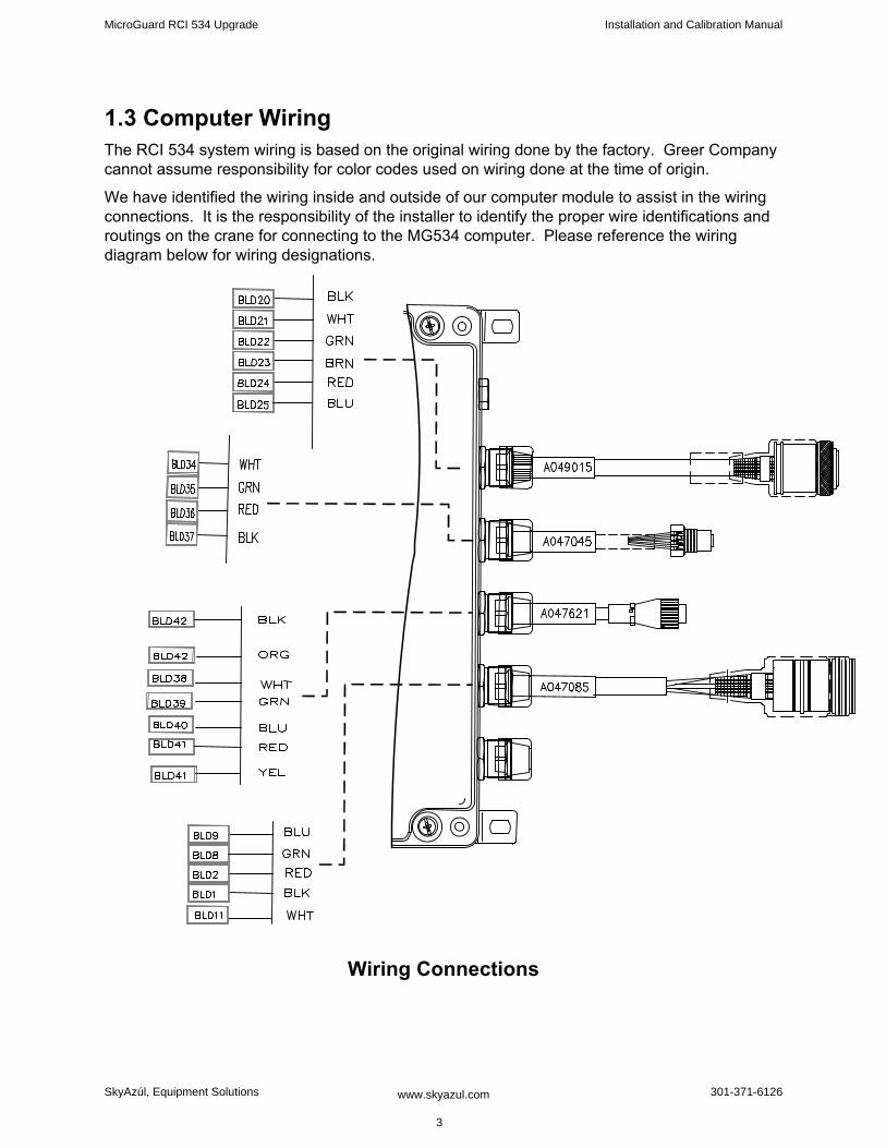
1.3 Computer Wiring The RCI 534 system wiring is based on the original wiring done by the factory. Greer Company cannot assume responsibility for color codes used on wiring done at the time of origin.
We have identified the wiring inside and outside of our computer module to assist in the wiring connections. It is the responsibility of the installer to identify the proper wire identifications and routings on the crane for connecting to the MG534 computer. Please reference the wiring diagram below for wiring designations.
Wiring Connections
MicroGuard RCI 534 Upgrade Installation and Calibration Manual
SkyAzúl, Equipment Solutions www.skyazul.com 3
301-371-6126

Connection Connection A450663 A450763 Work Instruction JP3-1Battery 0V BLD 1 Battery -VE Connect to Frame Ground
System Power JP3-2 BLD 2 Battery +VE Connect to Crane Power 12V - 36V (Fused at 10 Amp power source)
JP 5-1 Relay Power Feed
BLD 11 Relay Power Feed Incoming Crane Power for Function Kickout
JP 5-2 Solenoid Output BLD 8 Solenoid Output
Power to Function Kick Out Solenoids on Crane
Connection Connection A450663 A450763 Work Instruction JP 12-1 (Data "A") BLD 38 (Data "A") Display Communication connection JP 12-2 (Data "B") BLD 39 (Data "B") Display Communication connection JP 12-3 Reset BLD 40 Reset Reset line…..Usually Blue JP 12-4 Display Power BLD 41 Power 12V Power for Display JP 12-5 BLD 42 Display Ground Wire Connection Connection A450663 A450763 Work Instruction JP9-1 BLD 26 Digital Input (12V) JP9-2 BLD 27 Digital Input (12V) JP9-3 BLD 28 Digital Input (12V) JP9-4 BLD 29 Digital Input (12V) BLD30 12V Power Supply Connection Connection A450663 A450763 Work Instruction JP11-1 BLD 34 Drive Voltage for Swing Pot JP 11-2 BLD 35 Ground Signal for Swing Pot JP 11-3 BLD 36 Communication Connection JP 11-4 BLD 37 Communication Connection Connection Connection A450663 A450763 Work Instruction JP8-1 BLD 20 Monitored Voltage Signal Anti 2 Block JP8-2 BLD 21 Analog Signal from Ext. to Computer JP8-3 BLD 22 Analog Signal from Angle to Computer JP8-4 BLD 23 Monitored Voltage Signal Anti 2 Block JP8-5 BLD 24 Protected 5 Volts (Drive Voltage) JP8-6 BLD 25 Internal Ground (Drive Voltage)
MicroGuard RCI 534 Upgrade Installation and Calibration Manual
SkyAzúl, Equipment Solutions www.skyazul.com 4
301-371-6126
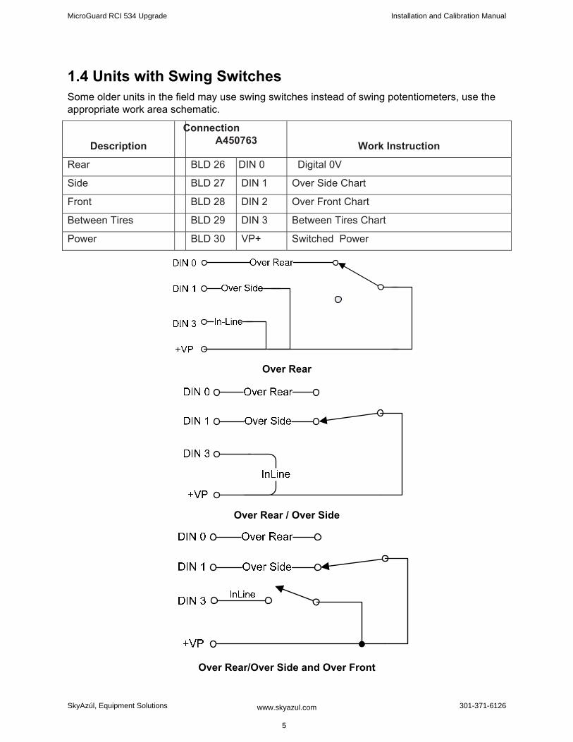
1.4 Units with Swing Switches Some older units in the field may use swing switches instead of swing potentiometers, use the appropriate work area schematic.
Description
Connection A450763
Work Instruction
Rear BLD 26 DIN 0 Digital 0V
Side BLD 27 DIN 1 Over Side Chart
Front BLD 28 DIN 2 Over Front Chart
Between Tires BLD 29 DIN 3 Between Tires Chart
Power BLD 30 VP+ Switched Power
Over Rear
Over Rear / Over Side
Over Rear/Over Side and Over Front
MicroGuard RCI 534 Upgrade Installation and Calibration Manual
SkyAzúl, Equipment Solutions www.skyazul.com 5
301-371-6126
1.5 Removal and Installation: 1. Place the crane in rigging mode and raise the boom. This will allow access to the hose
fittings and wiring harness connections.
NOTE: Leave the Power and FKO cable connected to allow movement of the boom during the removal and installation process.
2. Disconnect the extension reel cable.
3. Disconnect the swing sensor.
4. Remove the display.
5. Remove the display cable.
6. Unscrew the four bolts and remove the old computer from its mounting and place computer on the deck.
NOTE: Do not disconnect the power and FKO cables.
7. The new computer is smaller than the existing one. Mount the new computer using one of the existing bolt holes. Use the new computer as a template to drill three new mounting holes.
8. Screw in the remaining 3 bolts and ensure the computer is firmly attached.
9. Lower the boom completely. Remove the existing pressure sensors.
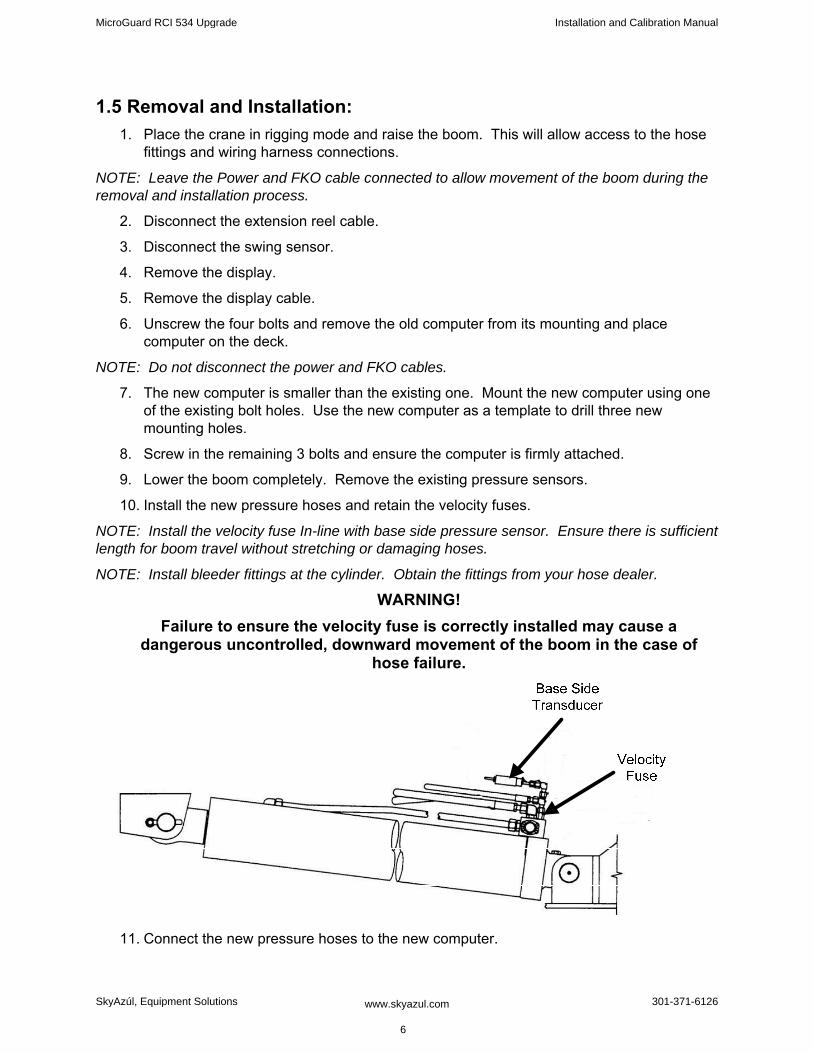
10. Install the new pressure hoses and retain the velocity fuses.
NOTE: Install the velocity fuse In-line with base side pressure sensor. Ensure there is sufficient length for boom travel without stretching or damaging hoses.
NOTE: Install bleeder fittings at the cylinder. Obtain the fittings from your hose dealer.
WARNING! Failure to ensure the velocity fuse is correctly installed may cause a
dangerous uncontrolled, downward movement of the boom in the case of hose failure.
11. Connect the new pressure hoses to the new computer.
MicroGuard RCI 534 Upgrade Installation and Calibration Manual
SkyAzúl, Equipment Solutions www.skyazul.com 6
301-371-6126

12. Raise the boom.
13. If using the existing reeling drum, disconnect the extension reel cable and remove. The new computer is wired with a new cable and only needs to be attached to the reeling drum. Install the display.
14. Install the display cable.
15. Install the power and FKO cables to the new computer.
16. Slowly elevate the boom to its Maximum Angle to ensure the pressure hoses and electrical cables are routed properly.
ATTENTION! It is easy to misroute the pressure hoses and electrical cables. If misrouted,
when the boom is raised the 1st time the hoses/cables can be damaged or destroyed. Use caution.
MicroGuard RCI 534 Upgrade Installation and Calibration Manual
SkyAzúl, Equipment Solutions www.skyazul.com 7
301-371-6126

Chapter 2 ‐ Calibration
MicroGuard RCI 534 Upgrade Installation and Calibration Manual
SkyAzúl, Equipment Solutions www.skyazul.com
8
301-371-6126
IntroductionThis manual describes the calibration process for the Link-Belt MG-534 Rated Capacity Indicator System (hereinafter referred to as “the system”) in an on-site environment and assumes that there is no prior knowledge of the geometry of the crane other than data provided by the manufacturer. This document also assists personnel in obtaining necessary measurements for calibration and in maintaining a record of the measurements and test results for review and/or comparison when changes are made. Recording measurements and test results during the calibration process will ensure an organized and easy to follow calibration.
Required Tools
1/4” nut driver or T15 Torx driver•
Digital or bubble level calibrated and accurate to 0.1° at level •
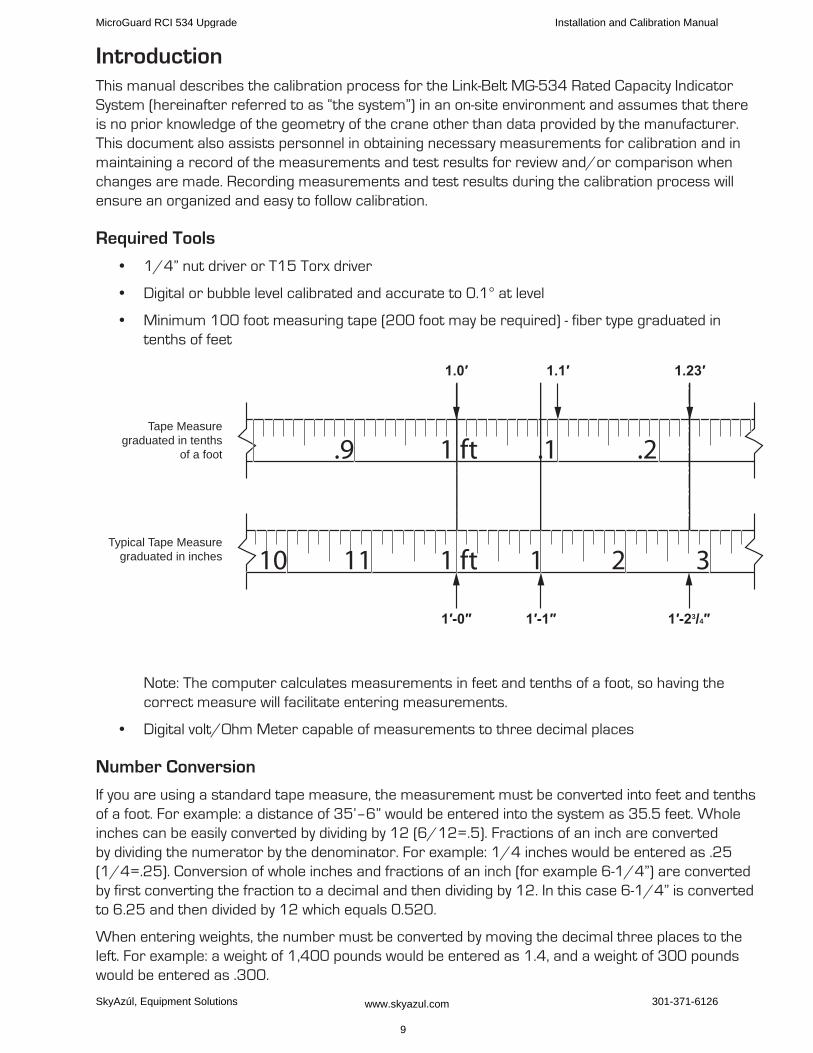
Minimum 100 foot measuring tape (200 foot may be required) - fiber type graduated in •tenths of feet
.9 1 ft .1 .2
10 11 1 ft 1 2 3
1.0′
1′-0″ 1′-1″ 1′-23/4″
1.1′ 1.23′
Typical Tape Measuregraduated in inches
Tape Measuregraduated in tenths
of a foot
Note: The computer calculates measurements in feet and tenths of a foot, so having the correct measure will facilitate entering measurements.
Digital volt/Ohm Meter capable of measurements to three decimal places•
Number Conversion
If you are using a standard tape measure, the measurement must be converted into feet and tenths of a foot. For example: a distance of 35’–6” would be entered into the system as 35.5 feet. Whole inches can be easily converted by dividing by 12 (6/12=.5). Fractions of an inch are converted by dividing the numerator by the denominator. For example: 1/4 inches would be entered as .25 (1/4=.25). Conversion of whole inches and fractions of an inch (for example 6-1/4”) are converted by first converting the fraction to a decimal and then dividing by 12. In this case 6-1/4” is converted to 6.25 and then divided by 12 which equals 0.520.
When entering weights, the number must be converted by moving the decimal three places to the left. For example: a weight of 1,400 pounds would be entered as 1.4, and a weight of 300 pounds would be entered as .300.
MicroGuard RCI 534 Upgrade Installation and Calibration Manual
SkyAzúl, Equipment Solutions www.skyazul.com 9
301-371-6126
Number Entry
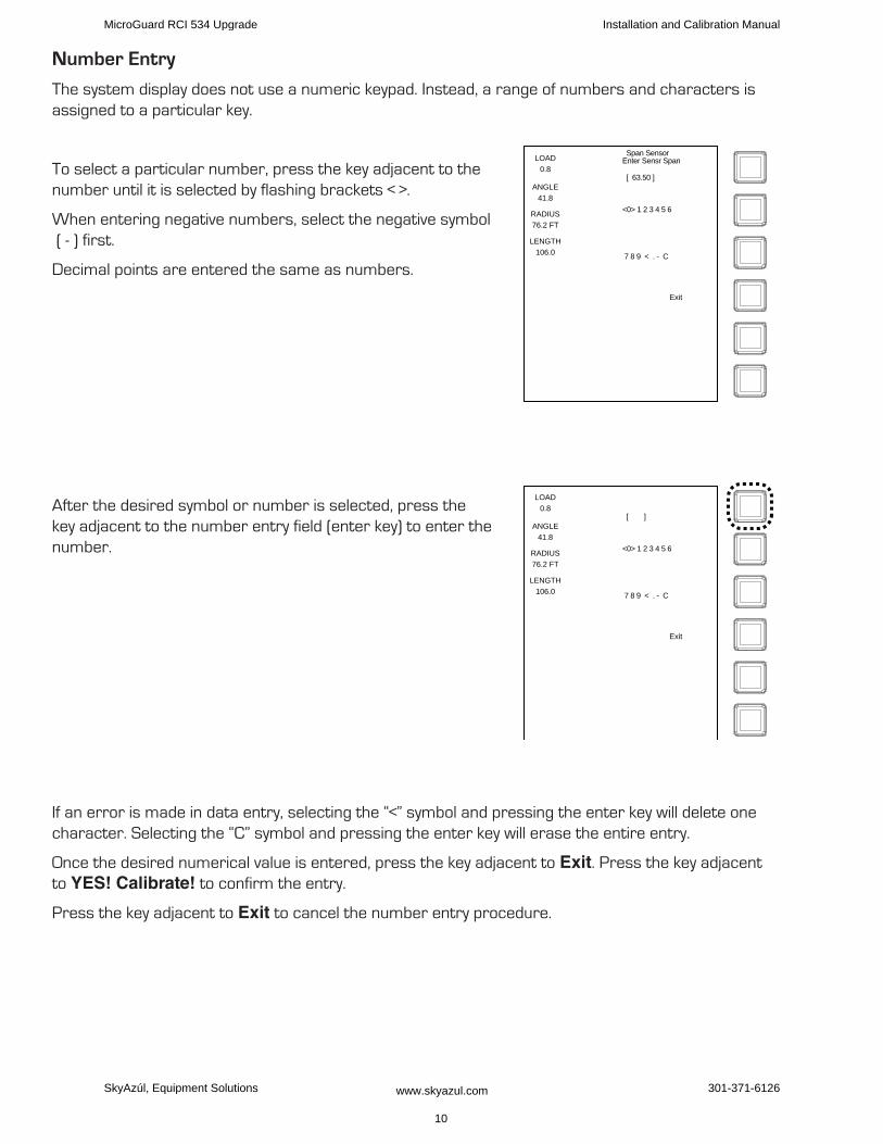
The system display does not use a numeric keypad. Instead, a range of numbers and characters is assigned to a particular key.
To select a particular number, press the key adjacent to the number until it is selected by flashing brackets < >.
When entering negative numbers, select the negative symbol ( - ) first.
Decimal points are entered the same as numbers.
After the desired symbol or number is selected, press the key adjacent to the number entry field (enter key) to enter the number.
If an error is made in data entry, selecting the “<” symbol and pressing the enter key will delete one character. Selecting the “C” symbol and pressing the enter key will erase the entire entry.
Once the desired numerical value is entered, press the key adjacent to Exit. Press the key adjacent to YES! Calibrate! to confirm the entry.
Press the key adjacent to Exit to cancel the number entry procedure.
LOAD
0.8
ANGLE
41.8
RADIUS
76.2 FT
LENGTH
106.0
Span SensorEnter Sensr Span
<0> 1 2 3 4 5 6
[ 63.50 ]
7 8 9 < . - C
Exit
LOAD
0.8
ANGLE
41.8
RADIUS
76.2 FT
LENGTH
106.0
<0> 1 2 3 4 5 6
[ ]
7 8 9 < . - C
Exit
MicroGuard RCI 534 Upgrade Installation and Calibration Manual
SkyAzúl, Equipment Solutions www.skyazul.com 10
301-371-6126
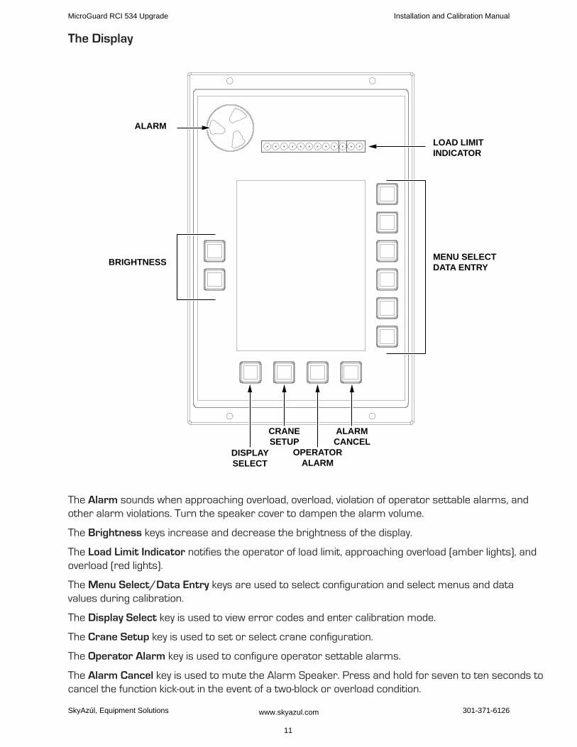
The Display
BRIGHTNESS
DISPLAYSELECT
CRANESETUP
OPERATORALARM
ALARMCANCEL
ALARM
MENU SELECTDATA ENTRY
LOAD LIMITINDICATOR
The Alarm sounds when approaching overload, overload, violation of operator settable alarms, and other alarm violations. Turn the speaker cover to dampen the alarm volume.
The Brightness keys increase and decrease the brightness of the display.
The Load Limit Indicator notifies the operator of load limit, approaching overload (amber lights), and overload (red lights).
The Menu Select/Data Entry keys are used to select configuration and select menus and data values during calibration.
The Display Select key is used to view error codes and enter calibration mode.
The Crane Setup key is used to set or select crane configuration.
The Operator Alarm key is used to configure operator settable alarms.
The Alarm Cancel key is used to mute the Alarm Speaker. Press and hold for seven to ten seconds to cancel the function kick-out in the event of a two-block or overload condition.
MicroGuard RCI 534 Upgrade Installation and Calibration Manual
SkyAzúl, Equipment Solutions www.skyazul.com 11
301-371-6126
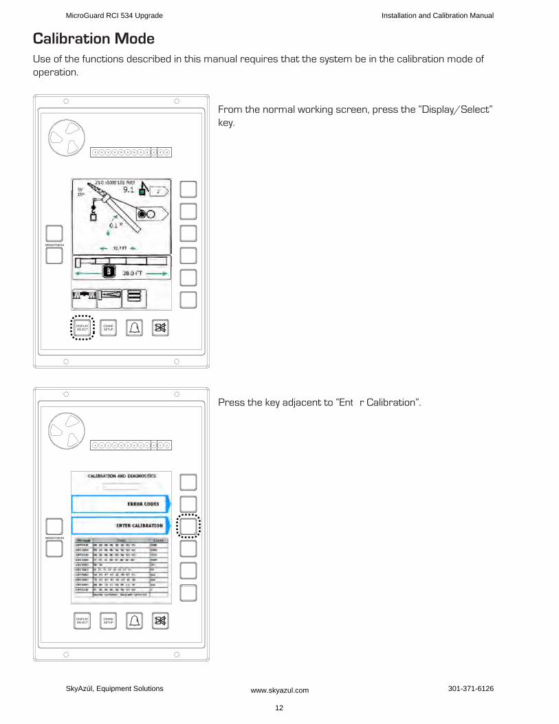
Calibration ModeUse of the functions described in this manual requires that the system be in the calibration mode of operation.
From the normal working screen, press the “Display/Select” key.
Press the key adjacent to “Ent r Calibration”.
BRIGHTNESS
DISPLAYSELECT
CRANESETUP
BRIGHTNESS
DISPLAYSELECT
CRANESETUP
MicroGuard RCI 534 Upgrade Installation and Calibration Manual
SkyAzúl, Equipment Solutions www.skyazul.com 12
301-371-6126
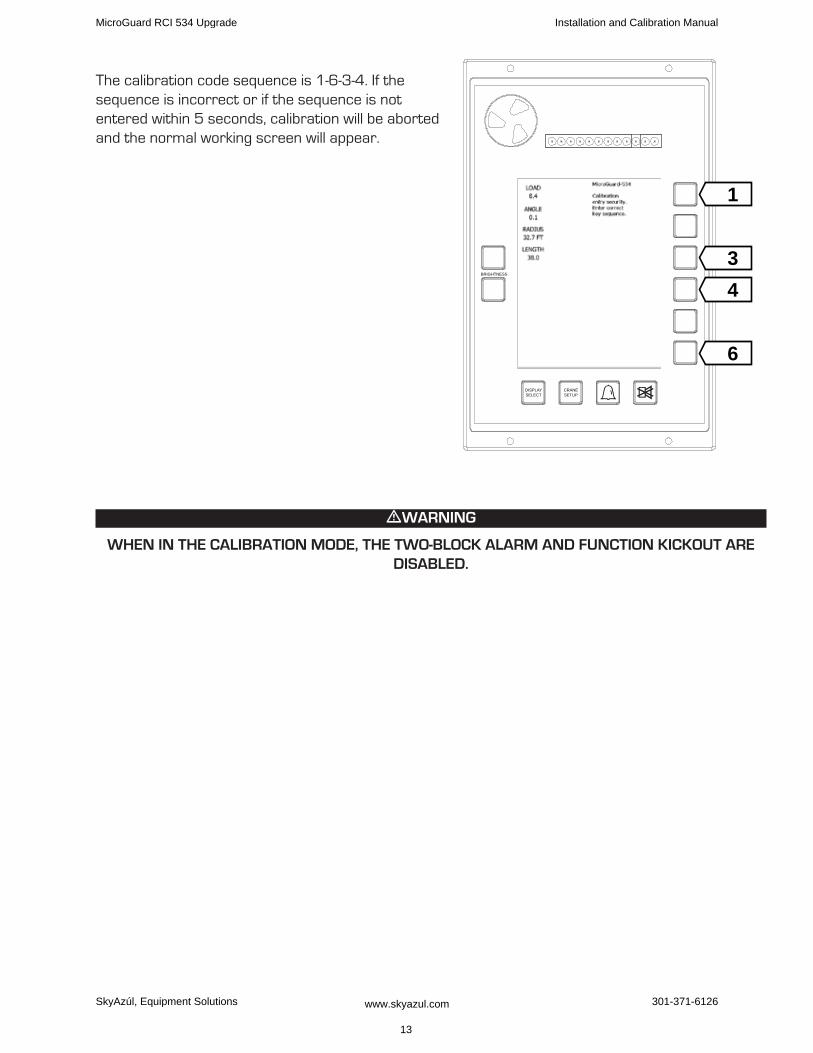
The calibration code sequence is 1-6-3-4. If the sequence is incorrect or if the sequence is not entered within 5 seconds, calibration will be aborted and the normal working screen will appear.
mWARNINg
WhEN IN ThE CALIBRATION MODE, ThE TWO-BLOCk ALARM AND fuNCTION kICkOuT ARE DISABLED.
BRIGHTNESS
DISPLAYSELECT
CRANESETUP
1
34
6
MicroGuard RCI 534 Upgrade Installation and Calibration Manual
SkyAzúl, Equipment Solutions www.skyazul.com 13
301-371-6126
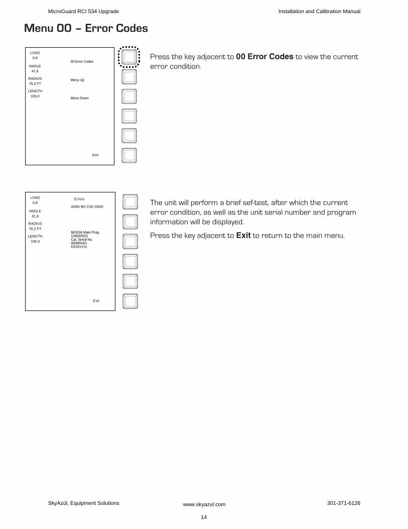
Menu 00 – Error Codes
Press the key adjacent to 00 Error Codes to view the current error condition.
The unit will perform a brief sef-test, after which the current error condition, as well as the unit serial number and program information will be displayed.
Press the key adjacent to Exit to return to the main menu.
00 Error Codes
Menu Up
Menu Down
Exit
LOAD
0.8
ANGLE
41.8
RADIUS
76.2 FT
LENGTH
106.0
LOAD
0.8
ANGLE
41.8
RADIUS
76.2 FT
LENGTH
106.0
Exit
Errors
A000 B0 C00 D000
MG534 Main Prog.G450052GCal. Serial No.0008504GD534147e
MicroGuard RCI 534 Upgrade Installation and Calibration Manual
SkyAzúl, Equipment Solutions www.skyazul.com 14
301-371-6126
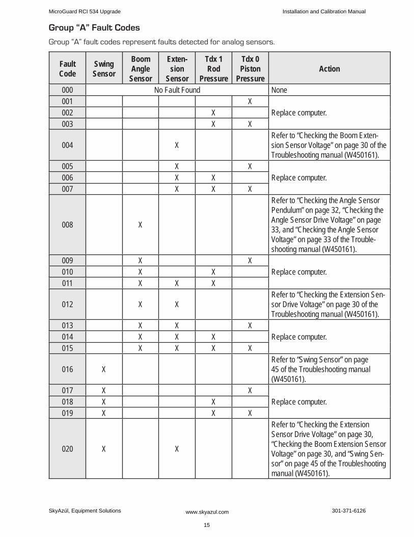
group “A” fault Codes
Group “A” fault codes represent faults detected for analog sensors.
Fault Code
Swing Sensor
Boom Angle
Sensor
Exten-sion
Sensor
Tdx 1 Rod
Pressure
Tdx 0 Piston
PressureAction
000 No Fault Found None001 X
Replace computer.002 X003 X X
004 XRefer to “Checking the Boom Exten-sion Sensor Voltage” on page 30 of the Troubleshooting manual (W450161).
005 X XReplace computer.006 X X
007 X X X
008 X
Refer to “Checking the Angle Sensor Pendulum” on page 32, “Checking the Angle Sensor Drive Voltage” on page 33, and “Checking the Angle Sensor Voltage” on page 33 of the Trouble-shooting manual (W450161).
009 X XReplace computer.010 X X
011 X X X
012 X XRefer to “Checking the Extension Sen-sor Drive Voltage” on page 30 of the Troubleshooting manual (W450161).
013 X X XReplace computer.014 X X X
015 X X X X
016 XRefer to “Swing Sensor” on page 45 of the Troubleshooting manual (W450161).
017 X XReplace computer.018 X X
019 X X X
020 X X
Refer to “Checking the Extension Sensor Drive Voltage” on page 30, “Checking the Boom Extension Sensor Voltage” on page 30, and “Swing Sen-sor” on page 45 of the Troubleshooting manual (W450161).
MicroGuard RCI 534 Upgrade Installation and Calibration Manual
SkyAzúl, Equipment Solutions www.skyazul.com 15
301-371-6126
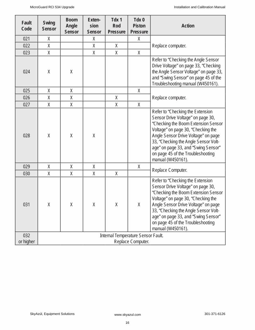
Fault Code
Swing Sensor
Boom Angle
Sensor
Exten-sion
Sensor
Tdx 1 Rod
Pressure
Tdx 0 Piston
PressureAction
021 X X XReplace computer.022 X X X
023 X X X X
024 X X
Refer to “Checking the Angle Sensor Drive Voltage” on page 33, “Checking the Angle Sensor Voltage” on page 33, and “Swing Sensor” on page 45 of the Troubleshooting manual (W450161).
025 X X XReplace computer.026 X X X
027 X X X X
028 X X X
Refer to “Checking the Extension Sensor Drive Voltage” on page 30, “Checking the Boom Extension Sensor Voltage” on page 30, “Checking the Angle Sensor Drive Voltage” on page 33, “Checking the Angle Sensor Volt-age” on page 33, and “Swing Sensor” on page 45 of the Troubleshooting manual (W450161).
029 X X X XReplace Computer.
030 X X X X
031 X X X X X
Refer to “Checking the Extension Sensor Drive Voltage” on page 30, “Checking the Boom Extension Sensor Voltage” on page 30, “Checking the Angle Sensor Drive Voltage” on page 33, “Checking the Angle Sensor Volt-age” on page 33, and “Swing Sensor” on page 45 of the Troubleshooting manual (W450161).
032 or higher
Internal Temperature Sensor Fault. Replace Computer.
MicroGuard RCI 534 Upgrade Installation and Calibration Manual
SkyAzúl, Equipment Solutions www.skyazul.com 16
301-371-6126
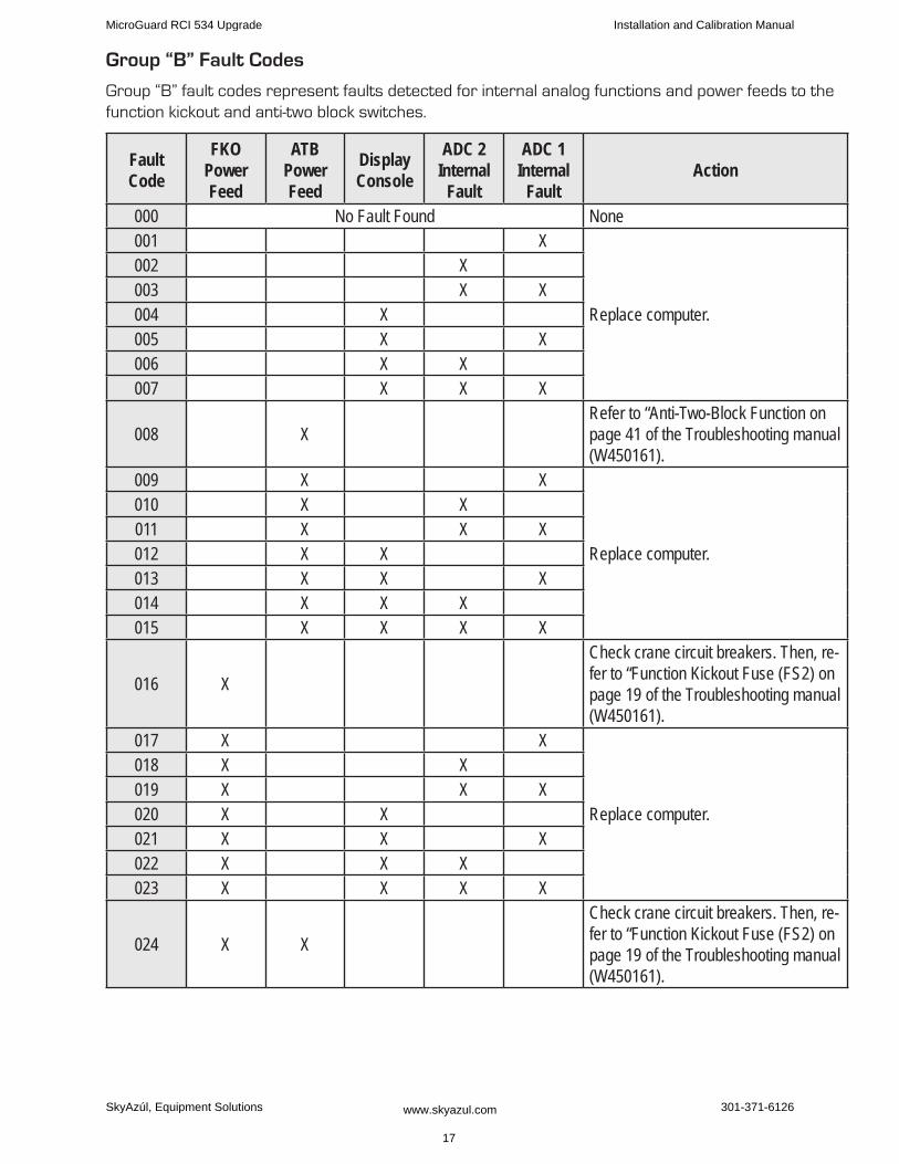
group “B” fault Codes
Group “B” fault codes represent faults detected for internal analog functions and power feeds to the function kickout and anti-two block switches.
Fault Code
FKO Power Feed
ATB Power Feed
Display Console
ADC 2 Internal
Fault
ADC 1 Internal
FaultAction
000 No Fault Found None001 X
Replace computer.
002 X003 X X004 X005 X X006 X X007 X X X
008 XRefer to “Anti-Two-Block Function on page 41 of the Troubleshooting manual (W450161).
009 X X
Replace computer.
010 X X011 X X X012 X X013 X X X014 X X X015 X X X X
016 X
Check crane circuit breakers. Then, re-fer to “Function Kickout Fuse (FS2) on page 19 of the Troubleshooting manual (W450161).
017 X X
Replace computer.
018 X X019 X X X020 X X021 X X X022 X X X023 X X X X
024 X X
Check crane circuit breakers. Then, re-fer to “Function Kickout Fuse (FS2) on page 19 of the Troubleshooting manual (W450161).
MicroGuard RCI 534 Upgrade Installation and Calibration Manual
SkyAzúl, Equipment Solutions www.skyazul.com 17
301-371-6126
Fault Code
FKO Power Feed
ATB Power Feed
Display Console
ADC 2 Internal
Fault
ADC 1 Internal
FaultAction
025 X X X
Replace computer.
026 X X X027 X X X X028 X X X029 X X X X030 X X X X031 X X X X X
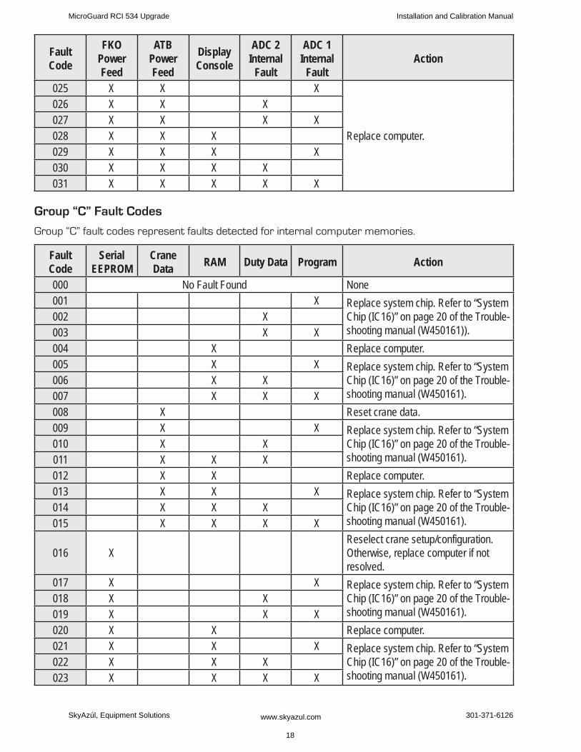
group “C” fault Codes
Group “C” fault codes represent faults detected for internal computer memories.
Fault Code
Serial EEPROM
Crane Data RAM Duty Data Program Action
000 No Fault Found None001 X Replace system chip. Refer to “System
Chip (IC16)” on page 20 of the Trouble-shooting manual (W450161)).
002 X003 X X004 X Replace computer.005 X X Replace system chip. Refer to “System
Chip (IC16)” on page 20 of the Trouble-shooting manual (W450161).
006 X X007 X X X008 X Reset crane data.009 X X Replace system chip. Refer to “System
Chip (IC16)” on page 20 of the Trouble-shooting manual (W450161).
010 X X011 X X X012 X X Replace computer.013 X X X Replace system chip. Refer to “System
Chip (IC16)” on page 20 of the Trouble-shooting manual (W450161).
014 X X X015 X X X X
016 XReselect crane setup/configuration. Otherwise, replace computer if not resolved.
017 X X Replace system chip. Refer to “System Chip (IC16)” on page 20 of the Trouble-shooting manual (W450161).
018 X X019 X X X020 X X Replace computer.021 X X X Replace system chip. Refer to “System
Chip (IC16)” on page 20 of the Trouble-shooting manual (W450161).
022 X X X023 X X X X
MicroGuard RCI 534 Upgrade Installation and Calibration Manual
SkyAzúl, Equipment Solutions www.skyazul.com 18
301-371-6126
Fault Code
Serial EEPROM
Crane Data RAM Duty Data Program Action
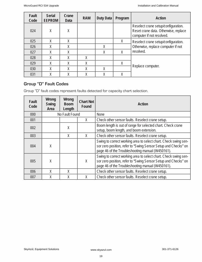
024 X XReselect crane setup/configuration. Reset crane data. Otherwise, replace computer if not resolved.
025 X X X Reselect crane setup/configuration. Otherwise, replace computer if not resolved.
026 X X X027 X X X X028 X X X
Replace computer.029 X X X X030 X X X X031 X X X X X
group “D” fault Codes
Group “D” fault codes represent faults detected for capacity chart selection.
Fault Code
Wrong Swing Area
Wrong Boom Length
Chart Not Found Action
000 No Fault Found None001 X Check other sensor faults. Reselect crane setup.
002 X Boom length is out of range for selected chart. Check crane setup, boom length, and boom extension.
003 X X Check other sensor faults. Reselect crane setup.
004 XSwing to correct working area to select chart. Check swing sen-sor zero position, refer to “Swing Sensor Setup and Checks” on page 46 of the Troubleshooting manual (W450161).
005 X XSwing to correct working area to select chart. Check swing sen-sor zero position, refer to “Swing Sensor Setup and Checks” on page 46 of the Troubleshooting manual (W450161).
006 X X Check other sensor faults. Reselect crane setup.007 X X X Check other sensor faults. Reselect crane setup.
MicroGuard RCI 534 Upgrade Installation and Calibration Manual
SkyAzúl, Equipment Solutions www.skyazul.com 19
301-371-6126

Menu 01 – Crane DatamWARNINg
PERfORMINg A CRANE DATA RESET WILL REPLACE CALIBRATED DATA WITh DATA STORED IN ThE SySTEM ChIP.
IMPORTANT!If ThIS IS NOT A PROTOTyPE CALIBRATION, ALL CALIBRATION DATA WILL BE STORED IN ThE SySTEM ChIP. IN ORDER TO MODIfy ThIS DATA, DOWNLOAD NEW OR ChANgED DATA, ThE
‘CRANE DATA RESET’ WILL NEED TO BE PERfORMED.
ALWAyS PERfORM CRANE DATA RESET ON A NEW OR PROTOTyPE SySTEM BEfORE BEgINNINg CALIBRATION OR TESTINg.
From the previous menu, press the key adjacent to Menu Up to go to “01 Crane Data”.
Press the key adjacent to 01 Crane Data.
The current crane data condition is displayed. If the display shows “Personality good”, the crane data is working properly.
If the display shows “Personality bad”, the crane data must be reset.
Press the key adjacent to Reset Crane Personality Data.
01 Crane Data
Menu Up
Menu Down
Exit
LOAD
0.8
ANGLE
41.8
RADIUS
76.2 FT
LENGTH
106.0
LOAD
0.8
ANGLE
41.8
RADIUS
76.2 FT
LENGTH
106.0
Crane Data
Personality good
Reset CranePersonality Data
Exit
MicroGuard RCI 534 Upgrade Installation and Calibration Manual
SkyAzúl, Equipment Solutions www.skyazul.com
20
301-371-6126
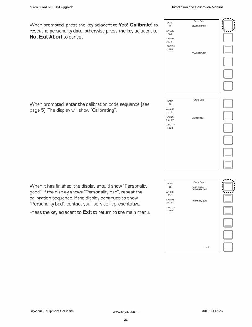
When prompted, press the key adjacent to Yes! Calibrate! to reset the personality data, otherwise press the key adjacent to No, Exit Abort to cancel.
When prompted, enter the calibration code sequence (see page 5). The display will show “Calibrating”.
When it has finished, the display should show “Personality good”. If the display shows “Personality bad”, repeat the calibration sequence. If the display continues to show “Personality bad”, contact your service representative.
Press the key adjacent to Exit to return to the main menu.
LOAD
0.8
ANGLE
41.8
RADIUS
76.2 FT
LENGTH
106.0
Crane Data
NO, Exit / Abort
YES! Calibrate!
LOAD
0.8
ANGLE
41.8
RADIUS
76.2 FT
LENGTH
106.0
Crane Data
Calibrating . .
LOAD
0.8
ANGLE
41.8
RADIUS
76.2 FT
LENGTH
106.0
Crane Data
Personality good
Reset CranePersonality Data
Exit
MicroGuard RCI 534 Upgrade Installation and Calibration Manual
SkyAzúl, Equipment Solutions www.skyazul.com 21
301-371-6126
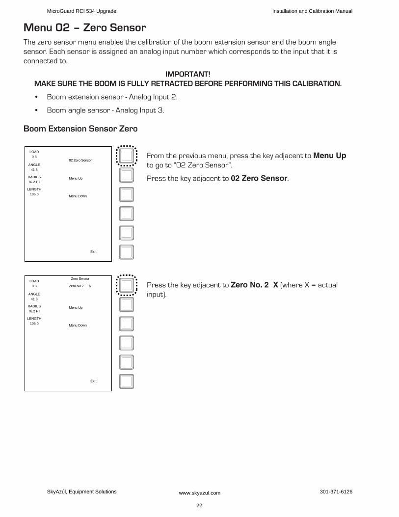
Menu 02 – Zero SensorThe zero sensor menu enables the calibration of the boom extension sensor and the boom angle sensor. Each sensor is assigned an analog input number which corresponds to the input that it is connected to.
IMPORTANT!MAkE SuRE ThE BOOM IS fuLLy RETRACTED BEfORE PERfORMINg ThIS CALIBRATION.
Boom extension sensor - Analog Input 2.•
Boom angle sensor - Analog Input 3.•
Boom Extension Sensor Zero
From the previous menu, press the key adjacent to Menu Up to go to “02 Zero Sensor”.
Press the key adjacent to 02 Zero Sensor.
Press the key adjacent to Zero No. 2 X (where X = actual input).
LOAD
0.8
ANGLE
41.8
RADIUS
76.2 FT
LENGTH
106.0
02 Zero Sensor
Menu Up
Menu Down
Exit
LOAD
0.8
ANGLE
41.8
RADIUS
76.2 FT
LENGTH
106.0
Zero No.2 6
Zero Sensor
Menu Up
Menu Down
Exit
MicroGuard RCI 534 Upgrade Installation and Calibration Manual
SkyAzúl, Equipment Solutions www.skyazul.com 22
301-371-6126

When prompted, press the key adjacent to Yes! Calibrate! to zero the sensor, otherwise press the key adjacent to No, Exit/ Abort to cancel.
When it has finished, the display should show “Zero No. 2 0” .
Press the key adjacent to Menu Up to go to the next sensor to be zeroed.
Boom Angle Sensor Zero
Using a digital level or inclinometer, set the boom to zero degrees (0°).
Press the key adjacent to Zero No. 3 X (where X = actual input).
LOAD
0.8
ANGLE
41.8
RADIUS
76.2 FT
LENGTH
106.0
Yes! Calibrate!
Zero Sensor
No, Exit / Abort
Exit
LOAD
0.8
ANGLE
41.8
RADIUS
76.2 FT
LENGTH
106.0
Zero No.2 0
Zero Sensor
Menu Up
Menu Down
Exit
LOAD
0.8
ANGLE
41.8
RADIUS
76.2 FT
LENGTH
106.0
Zero No.3 8
Zero Sensor
Menu Up
Menu Down
Exit
MicroGuard RCI 534 Upgrade Installation and Calibration Manual
SkyAzúl, Equipment Solutions www.skyazul.com 23
301-371-6126
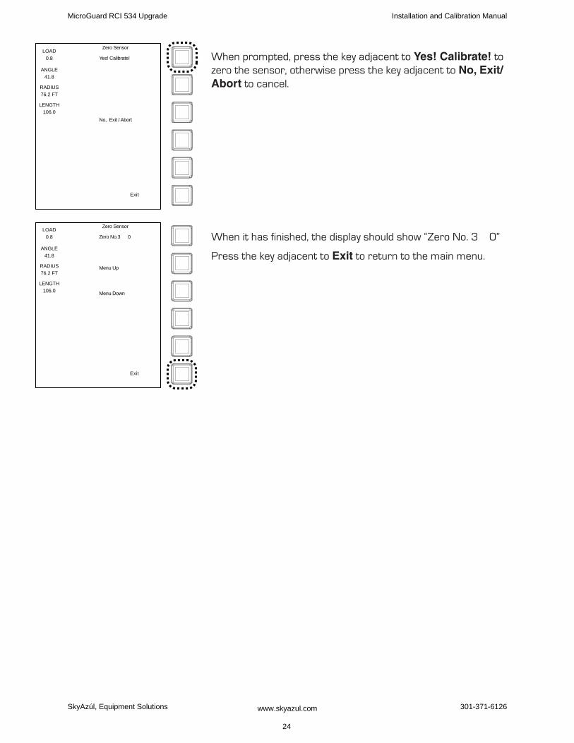
When prompted, press the key adjacent to Yes! Calibrate! to zero the sensor, otherwise press the key adjacent to No, Exit/Abort to cancel.
When it has finished, the display should show “Zero No. 3 0”
Press the key adjacent to Exit to return to the main menu.
LOAD
0.8
ANGLE
41.8
RADIUS
76.2 FT
LENGTH
106.0
Yes! Calibrate!
Zero Sensor
No, Exit / Abort
Exit
LOAD
0.8
ANGLE
41.8
RADIUS
76.2 FT
LENGTH
106.0
Zero No.3 0
Zero Sensor
Menu Up
Menu Down
Exit
MicroGuard RCI 534 Upgrade Installation and Calibration Manual
SkyAzúl, Equipment Solutions www.skyazul.com 24
301-371-6126
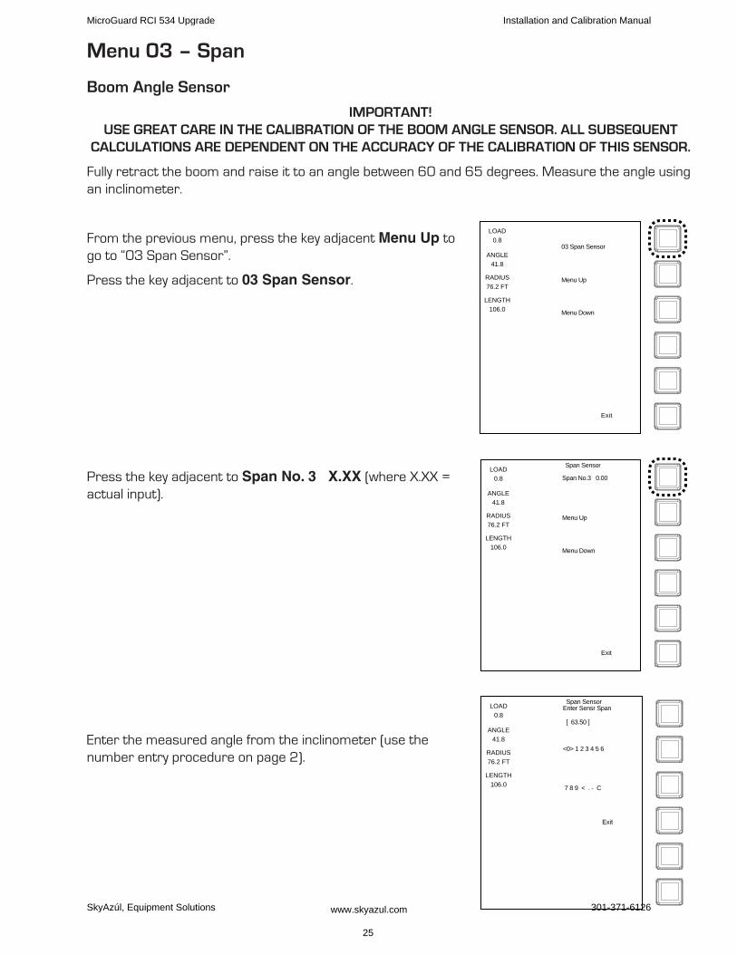
Menu 03 – Span
Boom Angle Sensor
IMPORTANT!uSE gREAT CARE IN ThE CALIBRATION Of ThE BOOM ANgLE SENSOR. ALL SuBSEquENT
CALCuLATIONS ARE DEPENDENT ON ThE ACCuRACy Of ThE CALIBRATION Of ThIS SENSOR.
Fully retract the boom and raise it to an angle between 60 and 65 degrees. Measure the angle using an inclinometer.
From the previous menu, press the key adjacent Menu Up to go to “03 Span Sensor”.
Press the key adjacent to 03 Span Sensor.
Press the key adjacent to Span No. 3 X.XX (where X.XX = actual input).
Enter the measured angle from the inclinometer (use the number entry procedure on page 2).
LOAD
0.8
ANGLE
41.8
RADIUS
76.2 FT
LENGTH
106.0
03 Span Sensor
Menu Up
Menu Down
Exit
LOAD
0.8
ANGLE
41.8
RADIUS
76.2 FT
LENGTH
106.0
Span Sensor
Span No.3 0.00
Menu Up
Menu Down
Exit
LOAD
0.8
ANGLE
41.8
RADIUS
76.2 FT
LENGTH
106.0
Span SensorEnter Sensr Span
<0> 1 2 3 4 5 6
[ 63.50 ]
7 8 9 < . - C
Exit
MicroGuard RCI 534 Upgrade Installation and Calibration Manual
SkyAzúl, Equipment Solutions www.skyazul.com 25
301-371-6126
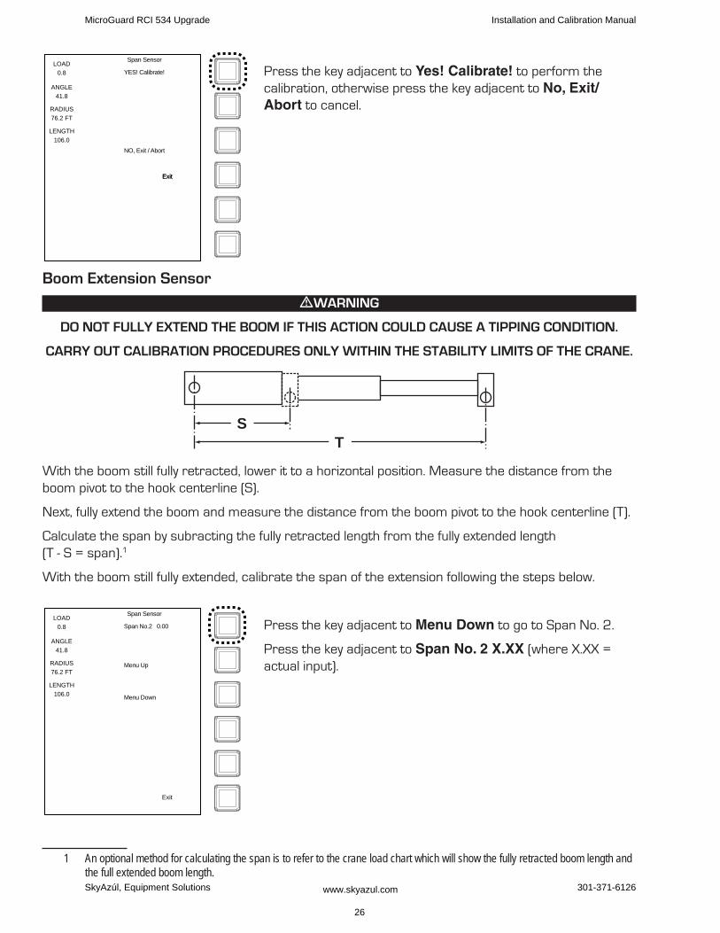
Press the key adjacent to Yes! Calibrate! to perform the calibration, otherwise press the key adjacent to No, Exit/Abort to cancel.
Boom Extension Sensor
mWARNINg
DO NOT fuLLy ExTEND ThE BOOM If ThIS ACTION COuLD CAuSE A TIPPINg CONDITION.
CARRy OuT CALIBRATION PROCEDuRES ONLy WIThIN ThE STABILITy LIMITS Of ThE CRANE.
TS
With the boom still fully retracted, lower it to a horizontal position. Measure the distance from the boom pivot to the hook centerline (S).
Next, fully extend the boom and measure the distance from the boom pivot to the hook centerline (T).
Calculate the span by subracting the fully retracted length from the fully extended length (T - S = span).1
With the boom still fully extended, calibrate the span of the extension following the steps below.
Press the key adjacent to Menu Down to go to Span No. 2.
Press the key adjacent to Span No. 2 X.XX (where X.XX = actual input).
1 An optional method for calculating the span is to refer to the crane load chart which will show the fully retracted boom length and the full extended boom length.
LOAD
0.8
ANGLE
41.8
RADIUS
76.2 FT
LENGTH
106.0
Span Sensor
YES! Calibrate!
NO, Exit / Abort
ExitExit
LOAD
0.8
ANGLE
41.8
RADIUS
76.2 FT
LENGTH
106.0
Span Sensor
Span No.2 0.00
Menu Up
Menu Down
Exit
MicroGuard RCI 534 Upgrade Installation and Calibration Manual
SkyAzúl, Equipment Solutions www.skyazul.com 26
301-371-6126
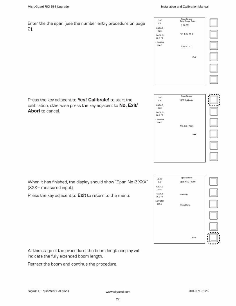
Enter the the span (use the number entry procedure on page 2).
Press the key adjacent to Yes! Calibrate! to start the calibration, otherwise press the key adjacent to No, Exit/Abort to cancel.
When it has finished, the display should show “Span No 2 XXX” (XXX= measured input).
Press the key adjacent to Exit to return to the menu.
At this stage of the procedure, the boom length display will indicate the fully extended boom length.
Retract the boom and continue the procedure.
LOAD
0.8
ANGLE
41.8
RADIUS
76.2 FT
LENGTH
106.0
Span SensorEnter Sensr Span
[ 96.00]
<0> 1 2 3 4 5 6
7 8 9 < . - C
Exit
LOAD
0.8
ANGLE
41.8
RADIUS
76.2 FT
LENGTH
106.0
Span Sensor
YES! Calibrate!
NO, Exit / Abort
ExitExit
LOAD
0.8
ANGLE
41.8
RADIUS
76.2 FT
LENGTH
106.0
Span Sensor
Span No.2 96.00
Menu Up
Menu Down
Exit
MicroGuard RCI 534 Upgrade Installation and Calibration Manual
SkyAzúl, Equipment Solutions www.skyazul.com 27
301-371-6126
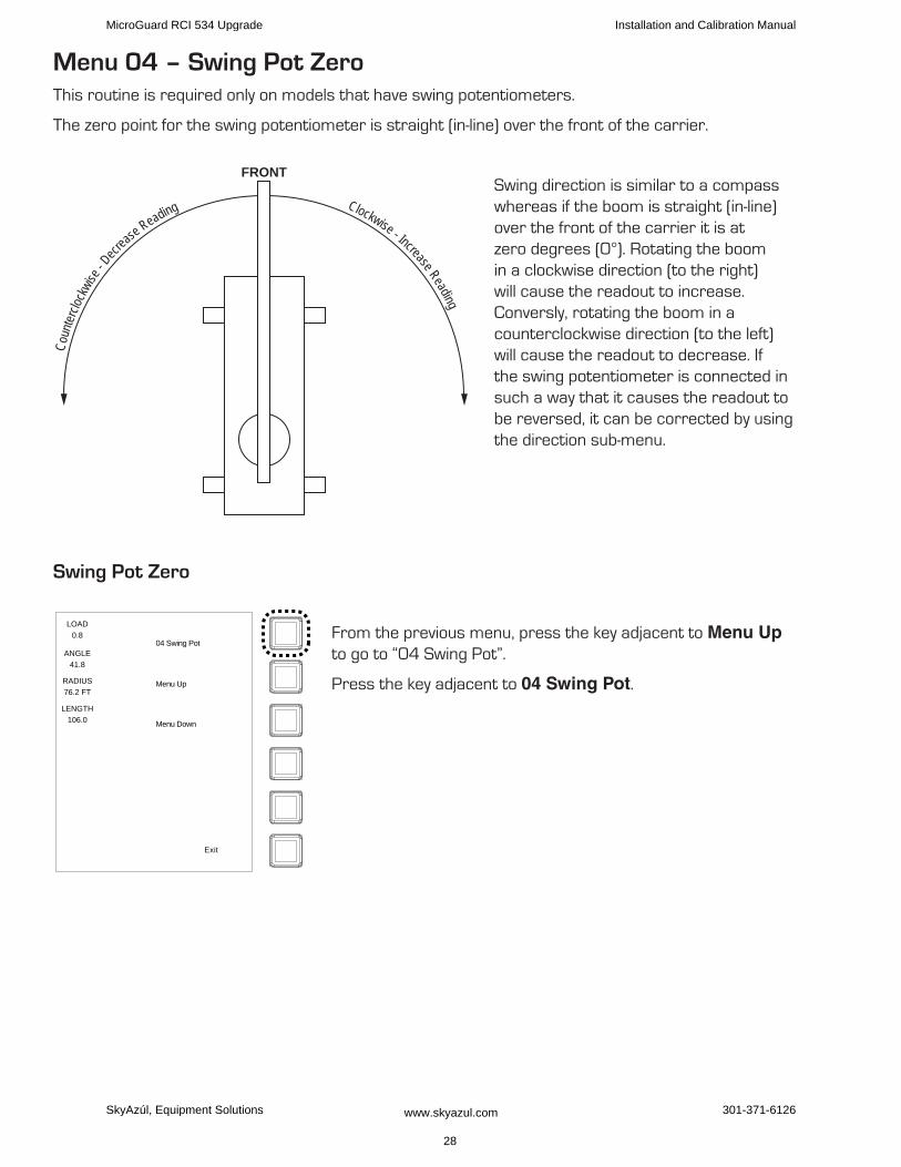
Menu 04 – Swing Pot ZeroThis routine is required only on models that have swing potentiometers.
The zero point for the swing potentiometer is straight (in-line) over the front of the carrier.
Swing direction is similar to a compass whereas if the boom is straight (in-line)over the front of the carrier it is at zero degrees (0°). Rotating the boom in a clockwise direction (to the right) will cause the readout to increase. Conversly, rotating the boom in a counterclockwise direction (to the left) will cause the readout to decrease. If the swing potentiometer is connected in such a way that it causes the readout to be reversed, it can be corrected by using the direction sub-menu.
Swing Pot Zero
From the previous menu, press the key adjacent to Menu Up to go to “04 Swing Pot”.
Press the key adjacent to 04 Swing Pot.
Clockwise - Increase Reading
Coun
terclo
ckwis
e - Decr
ease Reading
FRONT
LOAD
0.8
ANGLE
41.8
RADIUS
76.2 FT
LENGTH
106.0
04 Swing Pot
Menu Up
Menu Down
Exit
MicroGuard RCI 534 Upgrade Installation and Calibration Manual
SkyAzúl, Equipment Solutions www.skyazul.com 28
301-371-6126
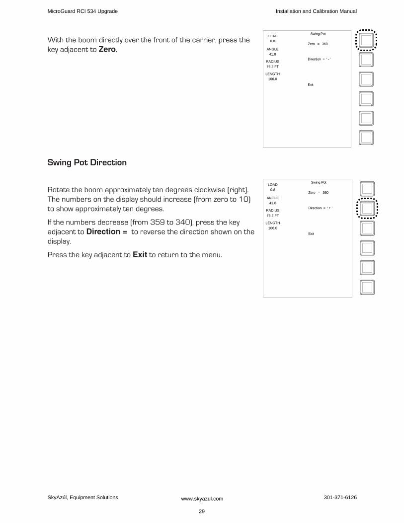
With the boom directly over the front of the carrier, press the key adjacent to Zero.
Swing Pot Direction
Rotate the boom approximately ten degrees clockwise (right). The numbers on the display should increase (from zero to 10) to show approximately ten degrees.
If the numbers decrease (from 359 to 340), press the key adjacent to Direction = to reverse the direction shown on the display.
Press the key adjacent to Exit to return to the menu.
LOAD
0.8
ANGLE
41.8
RADIUS
76.2 FT
LENGTH
106.0
Swing Pot
Zero = 360
Direction = ‘ - ’
Exit
LOAD
0.8
ANGLE
41.8
RADIUS
76.2 FT
LENGTH
106.0
Swing Pot
Zero = 360
Direction = ‘ + ’
Exit
MicroGuard RCI 534 Upgrade Installation and Calibration Manual
SkyAzúl, Equipment Solutions www.skyazul.com 29
301-371-6126
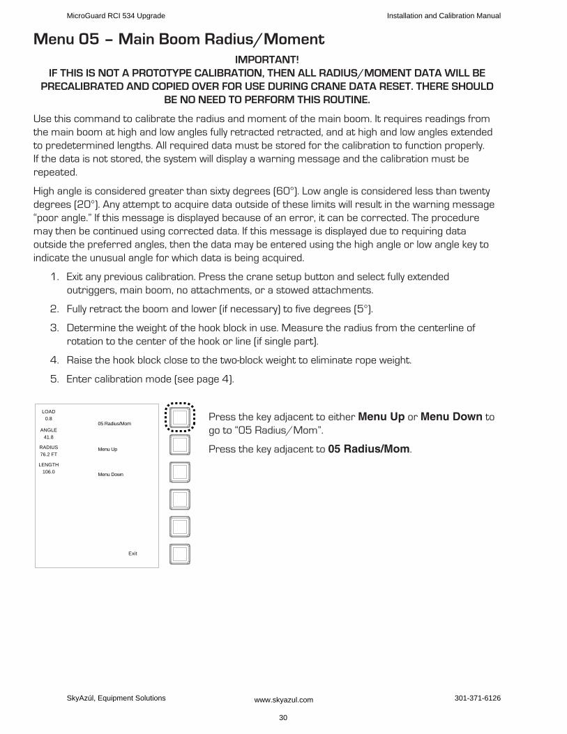
Menu 05 – Main Boom Radius/MomentIMPORTANT!
If ThIS IS NOT A PROTOTyPE CALIBRATION, ThEN ALL RADIuS/MOMENT DATA WILL BE PRECALIBRATED AND COPIED OvER fOR uSE DuRINg CRANE DATA RESET. ThERE ShOuLD
BE NO NEED TO PERfORM ThIS ROuTINE.
Use this command to calibrate the radius and moment of the main boom. It requires readings from the main boom at high and low angles fully retracted retracted, and at high and low angles extended to predetermined lengths. All required data must be stored for the calibration to function properly. If the data is not stored, the system will display a warning message and the calibration must be repeated.
High angle is considered greater than sixty degrees (60°). Low angle is considered less than twenty degrees (20°). Any attempt to acquire data outside of these limits will result in the warning message “poor angle.” If this message is displayed because of an error, it can be corrected. The procedure may then be continued using corrected data. If this message is displayed due to requiring data outside the preferred angles, then the data may be entered using the high angle or low angle key to indicate the unusual angle for which data is being acquired.
Exit any previous calibration. Press the crane setup button and select fully extended 1. outriggers, main boom, no attachments, or a stowed attachments.
Fully retract the boom and lower (if necessary) to five degrees (5°).2.
Determine the weight of the hook block in use. Measure the radius from the centerline of 3. rotation to the center of the hook or line (if single part).
Raise the hook block close to the two-block weight to eliminate rope weight.4.
Enter calibration mode (5. see page 4).
Press the key adjacent to either Menu Up or Menu Down to go to “05 Radius/Mom”.
Press the key adjacent to 05 Radius/Mom.
LOAD
0.8
ANGLE
41.8
RADIUS
76.2 FT
LENGTH
106.0
05 Radius/Mom
Menu Up
Menu Down
Exit
MicroGuard RCI 534 Upgrade Installation and Calibration Manual
SkyAzúl, Equipment Solutions www.skyazul.com 30
301-371-6126
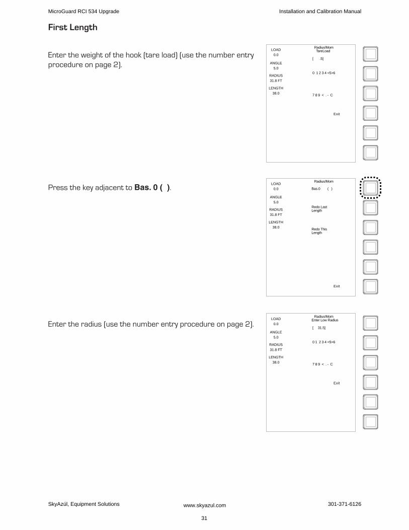
first Length
Enter the weight of the hook (tare load) (use the number entry procedure on page 2).
Press the key adjacent to Bas. 0 ( ).
Enter the radius (use the number entry procedure on page 2).
LOAD
0.0
ANGLE
5.0
RADIUS
31.8 FT
LENGTH
38.0
Radius/Mom TareLoad
0 1 2 3 4 <5>6
[ .5]
7 8 9 < . - C
Exit
LOAD
0.0
ANGLE
5.0
RADIUS
31.8 FT
LENGTH
38.0
Radius/Mom
Redo LastLength
Bas.0 ( )
Redo ThisLength
Exit
LOAD
0.0
ANGLE
5.0
RADIUS
31.8 FT
LENGTH
38.0
Radius/MomEnter Low Radius
0 1 2 3 4 <5>6
[ 31.5]
7 8 9 < . - C
Exit
MicroGuard RCI 534 Upgrade Installation and Calibration Manual
SkyAzúl, Equipment Solutions www.skyazul.com 31
301-371-6126

The display will show “BAS. 0 (D )”.
Press the key adjacent to Bas. 0 (D ).
Raise the retracted boom to a high angle.
Measure the radius.
Enter the radius (use the number entry procedure on page 2).
The display will show “Bas. 0 (DU)”.
Press the key adjacent to Bas. 0 (DU).
LOAD
0.0
ANGLE
5.0
RADIUS
31.8 FT
LENGTH
38.0
Radius/Mom
Redo LastLength
Bas.0 (D )
Redo ThisLength
Exit
LOAD
21.1
ANGLE
67.3
RADIUS
10.7 FT
LENGTH
38.0
Radius/MomEnter Hi Radius
0 1 2 3 4 5 <6>
[ 8.36]
7 8 9 < . - C
Exit
LOAD
21.1
ANGLE
67.4
RADIUS
10.7 FT
LENGTH
38.0
Radius/Mom
Redo LastLength
Bas.0 (DU)
Redo ThisLength
Exit
MicroGuard RCI 534 Upgrade Installation and Calibration Manual
SkyAzúl, Equipment Solutions www.skyazul.com
32
301-371-6126
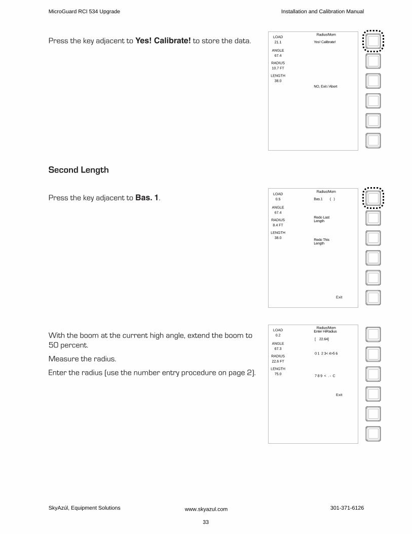
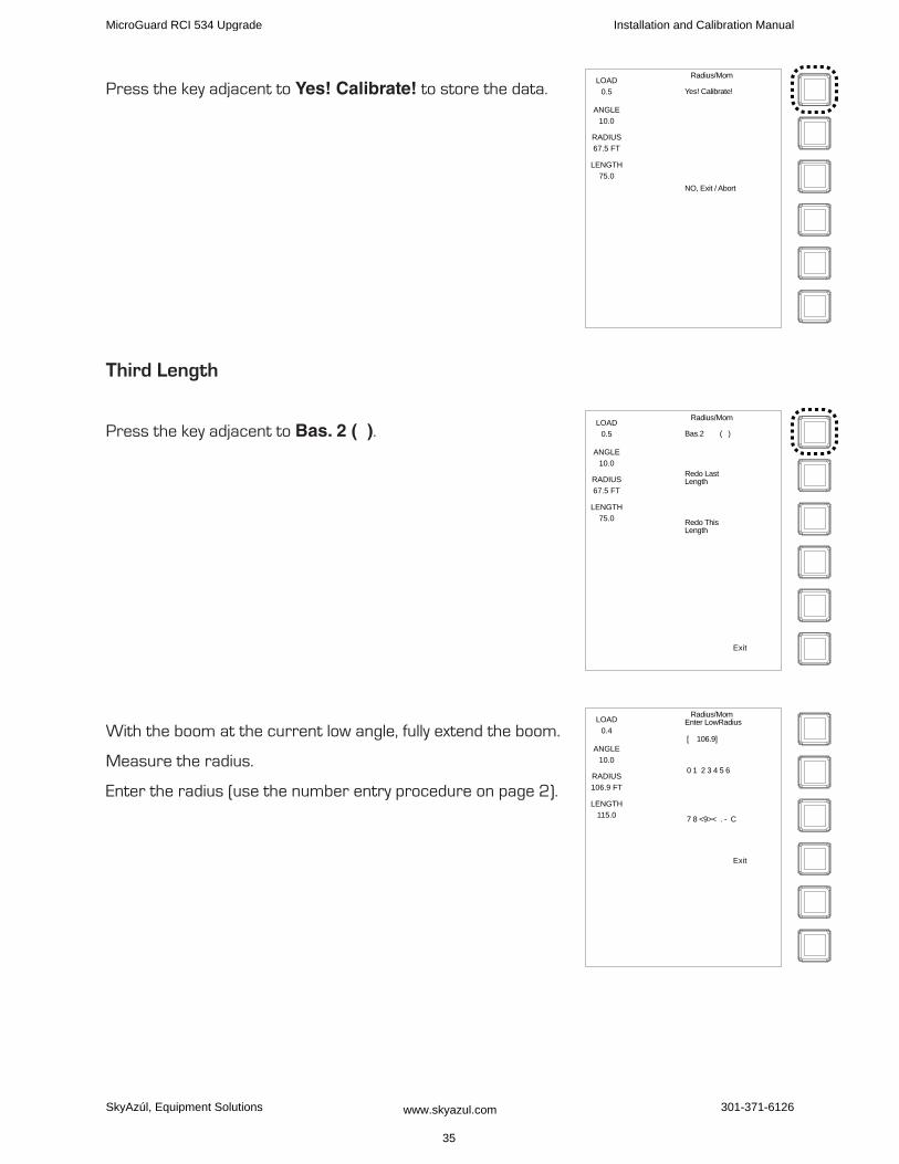
Press the key adjacent to Yes! Calibrate! to store the data.
Second Length
Press the key adjacent to Bas. 1.
With the boom at the current high angle, extend the boom to 50 percent.
Measure the radius.
Enter the radius (use the number entry procedure on page 2).
LOAD
21.1
ANGLE
67.4
RADIUS
10.7 FT
LENGTH
38.0
Radius/Mom
Yes! Calibrate!
NO, Exit / Abort
LOAD
0.5
ANGLE
67.4
RADIUS
8.4 FT
LENGTH
38.0
Radius/Mom
Redo LastLength
Bas.1 ( )
Redo ThisLength
Exit
LOAD
0.2
ANGLE
67.3
RADIUS
22.6 FT
LENGTH
75.0
Radius/MomEnter HiRadius
0 1 2 3< 4>5 6
[ 22.64]
7 8 9 < . - C
Exit
MicroGuard RCI 534 Upgrade Installation and Calibration Manual
SkyAzúl, Equipment Solutions www.skyazul.com 33
301-371-6126
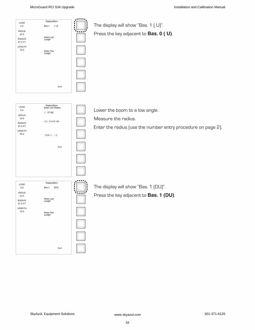
The display will show “Bas. 1 ( U)”.
Press the key adjacent to Bas. 0 ( U).
Lower the boom to a low angle.
Measure the radius.
Enter the radius (use the number entry procedure on page 2).
The display will show “Bas. 1 (DU)”.
Press the key adjacent to Bas. 1 (DU).
LOAD
0.5
ANGLE
10.0
RADIUS
67.5 FT
LENGTH
75.0
Radius/Mom
Redo LastLength
Bas.1 ( U)
Redo ThisLength
Exit
LOAD
0.5
ANGLE
10.0
RADIUS
67.5 FT
LENGTH
75.0
Radius/MomEnter Low Radius
0 1 2 3 4 5 <6>
[ 67.56]
7 8 9 < . - C
Exit
LOAD
0.5
ANGLE
10.0
RADIUS
67.5 FT
LENGTH
75.0
Radius/Mom
Redo LastLength
Bas.1 (DU)
Redo ThisLength
Exit
MicroGuard RCI 534 Upgrade Installation and Calibration Manual
SkyAzúl, Equipment Solutions www.skyazul.com 34
301-371-6126
Press the key adjacent to Yes! Calibrate! to store the data.
Third Length
Press the key adjacent to Bas. 2 ( ).
With the boom at the current low angle, fully extend the boom.
Measure the radius.
Enter the radius (use the number entry procedure on page 2).
Radius/Mom
Yes! Calibrate!
NO, Exit / Abort
LOAD
0.5
ANGLE
10.0
RADIUS
67.5 FT
LENGTH
75.0
LOAD
0.5
ANGLE
10.0
RADIUS
67.5 FT
LENGTH
75.0
Radius/Mom
Redo LastLength
Bas.2 ( )
Redo ThisLength
Exit
LOAD
0.4
ANGLE
10.0
RADIUS
106.9 FT
LENGTH
115.0
Radius/MomEnter LowRadius
0 1 2 3 4 5 6
[ 106.9]
7 8 <9>< . - C
Exit
MicroGuard RCI 534 Upgrade Installation and Calibration Manual
SkyAzúl, Equipment Solutions www.skyazul.com 35
301-371-6126
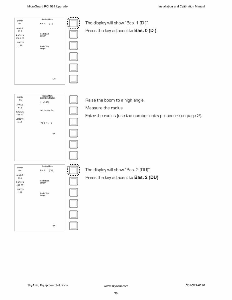
The display will show “Bas. 1 (D )”.
Press the key adjacent to Bas. 0 (D ).
Raise the boom to a high angle.
Measure the radius.
Enter the radius (use the number entry procedure on page 2).
The display will show “Bas. 2 (DU)”.
Press the key adjacent to Bas. 2 (DU).
LOAD
0.4
ANGLE
10.0
RADIUS
106.9 FT
LENGTH
115.0
Radius/Mom
Redo LastLength
Bas.2 (D )
Redo ThisLength
Exit
LOAD
0.5
ANGLE
64.1
RADIUS
43.9 FT
LENGTH
115.0
Radius/MomEnter Low Radius
0 1 2<3> 4 5 6
[ 43.93]
7 8 9 < . - C
Exit
LOAD
0.5
ANGLE
64.1
RADIUS
43.9 FT
LENGTH
115.0
Radius/Mom
Redo LastLength
Bas.2 (DU)
Redo ThisLength
Exit
MicroGuard RCI 534 Upgrade Installation and Calibration Manual
SkyAzúl, Equipment Solutions www.skyazul.com 36
301-371-6126

Press the key adjacent to Yes! Calibrate! to store the data. Radius/Mom
Yes! Calibrate!
NO, Exit / Abort
LOAD
0.5
ANGLE
64.1
RADIUS
43.9 FT
LENGTH
115.0
MicroGuard RCI 534 Upgrade Installation and Calibration Manual
SkyAzúl, Equipment Solutions www.skyazul.com 37
301-371-6126
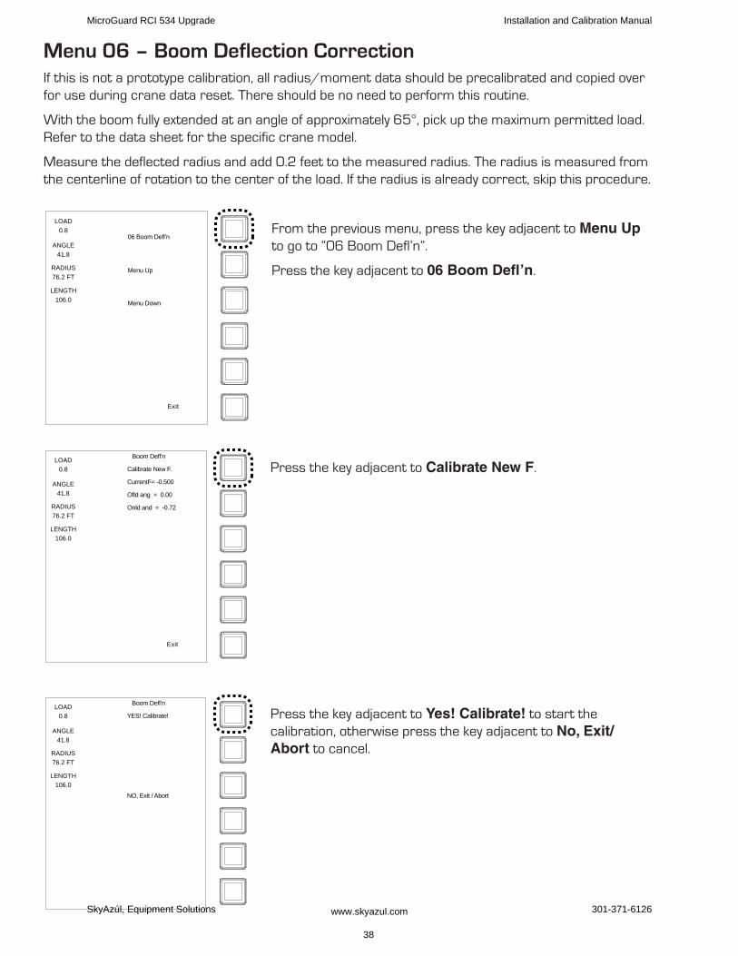
Menu 06 – Boom Deflection CorrectionIf this is not a prototype calibration, all radius/moment data should be precalibrated and copied over for use during crane data reset. There should be no need to perform this routine.
With the boom fully extended at an angle of approximately 65°, pick up the maximum permitted load. Refer to the data sheet for the specific crane model.
Measure the deflected radius and add 0.2 feet to the measured radius. The radius is measured from the centerline of rotation to the center of the load. If the radius is already correct, skip this procedure.
From the previous menu, press the key adjacent to Menu Up to go to “06 Boom Defl’n”.
Press the key adjacent to 06 Boom Defl’n.
Press the key adjacent to Calibrate New F.
Press the key adjacent to Yes! Calibrate! to start the calibration, otherwise press the key adjacent to No, Exit/Abort to cancel.
LOAD
0.8
ANGLE
41.8
RADIUS
76.2 FT
LENGTH
106.0
06 Boom Defl’n
Menu Up
Menu Down
Exit
LOAD
0.8
ANGLE
41.8
RADIUS
76.2 FT
LENGTH
106.0
Boom Defl’n
Calibrate New F.
CurrentF= -0.500
Ofld ang = 0.00
Onld and = -0.72
Exit
LOAD
0.8
ANGLE
41.8
RADIUS
76.2 FT
LENGTH
106.0
Boom Defl’n
YES! Calibrate!
NO, Exit / Abort
MicroGuard RCI 534 Upgrade Installation and Calibration Manual
SkyAzúl, Equipment Solutions www.skyazul.com 38
301-371-6126
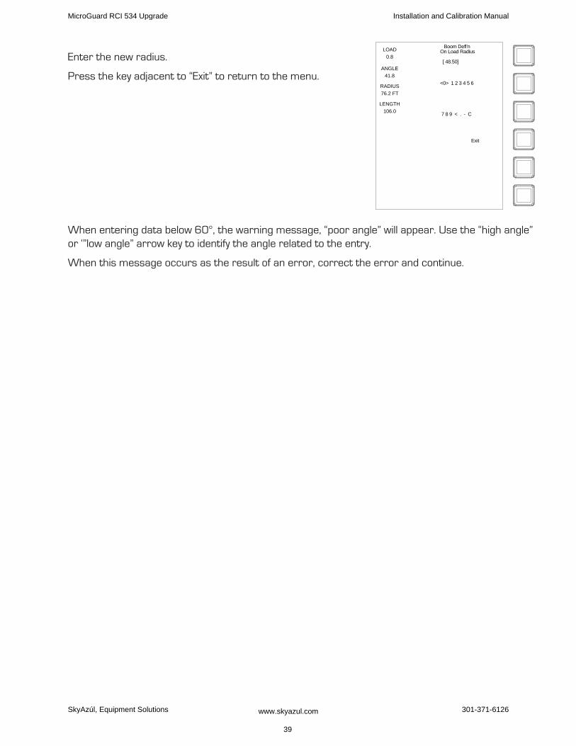
Enter the new radius.
Press the key adjacent to “Exit” to return to the menu.
When entering data below 60°, the warning message, “poor angle” will appear. Use the “high angle” or ‘”low angle” arrow key to identify the angle related to the entry.
When this message occurs as the result of an error, correct the error and continue.
LOAD
0.8
ANGLE
41.8
RADIUS
76.2 FT
LENGTH
106.0
Boom Defl’nOn Load Radius
[ 48.50]
<0> 1 2 3 4 5 6
7 8 9 < . - C
Exit
MicroGuard RCI 534 Upgrade Installation and Calibration Manual
SkyAzúl, Equipment Solutions www.skyazul.com 39
301-371-6126
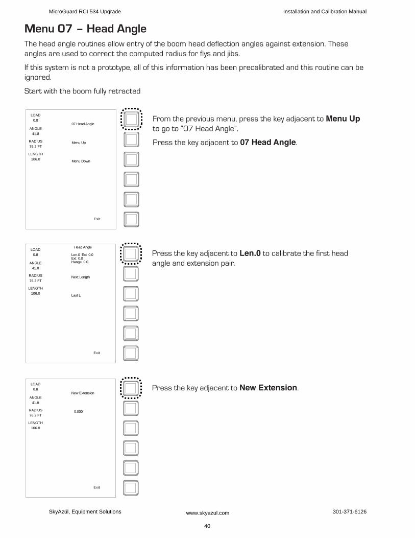
Menu 07 – head AngleThe head angle routines allow entry of the boom head deflection angles against extension. These angles are used to correct the computed radius for flys and jibs.
If this system is not a prototype, all of this information has been precalibrated and this routine can be ignored.
Start with the boom fully retracted
From the previous menu, press the key adjacent to Menu Up to go to “07 Head Angle”.
Press the key adjacent to 07 Head Angle.
Press the key adjacent to Len.0 to calibrate the first head angle and extension pair.
Press the key adjacent to New Extension.
LOAD
0.8
ANGLE
41.8
RADIUS
76.2 FT
LENGTH
106.0
07 Head Angle
Menu Up
Menu Down
Exit
LOAD
0.8
ANGLE
41.8
RADIUS
76.2 FT
LENGTH
106.0
Head Angle
Next Length
Len.0 Ext 0.0Ext 0.0Hang= 0.0
Last L
Exit
LOAD
0.8
ANGLE
41.8
RADIUS
76.2 FT
LENGTH
106.0
0.000
New Extension
Exit
MicroGuard RCI 534 Upgrade Installation and Calibration Manual
SkyAzúl, Equipment Solutions www.skyazul.com 40
301-371-6126

Press the key adjacent to Yes! Calibrate! to start the calibration, otherwise press the key adjacent to No, Exit/Abort to cancel.
Enter the current extension (use the number entry procedure on page 2).
Press the key adjacent to New Head Angle.
LOAD
0.8
ANGLE
41.8
RADIUS
76.2 FT
LENGTH
106.0
YES! Calibrate!
NO, Exit / Abort
LOAD
0.8
ANGLE
41.8
RADIUS
76.2 FT
LENGTH
106.0
New Extension
<0> 1 2 3 4 5 6
7 8 9 < . - C
Exit
[ ]
LOAD
0.8
ANGLE
41.8
RADIUS
76.2 FT
LENGTH
106.0
New Head Angle
0.000
Exit
MicroGuard RCI 534 Upgrade Installation and Calibration Manual
SkyAzúl, Equipment Solutions www.skyazul.com 41
301-371-6126
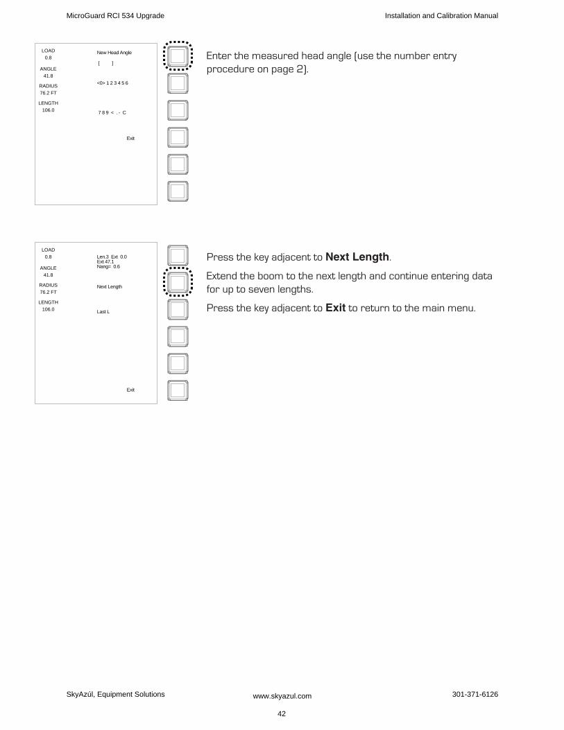
Enter the measured head angle (use the number entry procedure on page 2).
Press the key adjacent to Next Length.
Extend the boom to the next length and continue entering data for up to seven lengths.
Press the key adjacent to Exit to return to the main menu.
LOAD
0.8
ANGLE
41.8
RADIUS
76.2 FT
LENGTH
106.0
New Head Angle
<0> 1 2 3 4 5 6
7 8 9 < . - C
[ ]
Exit
LOAD
0.8
ANGLE
41.8
RADIUS
76.2 FT
LENGTH
106.0
Len.3 Ext 0.0Ext 47.1Nang= 0.6
Next Length
Last L
Exit
MicroGuard RCI 534 Upgrade Installation and Calibration Manual
SkyAzúl, Equipment Solutions www.skyazul.com 42
301-371-6126
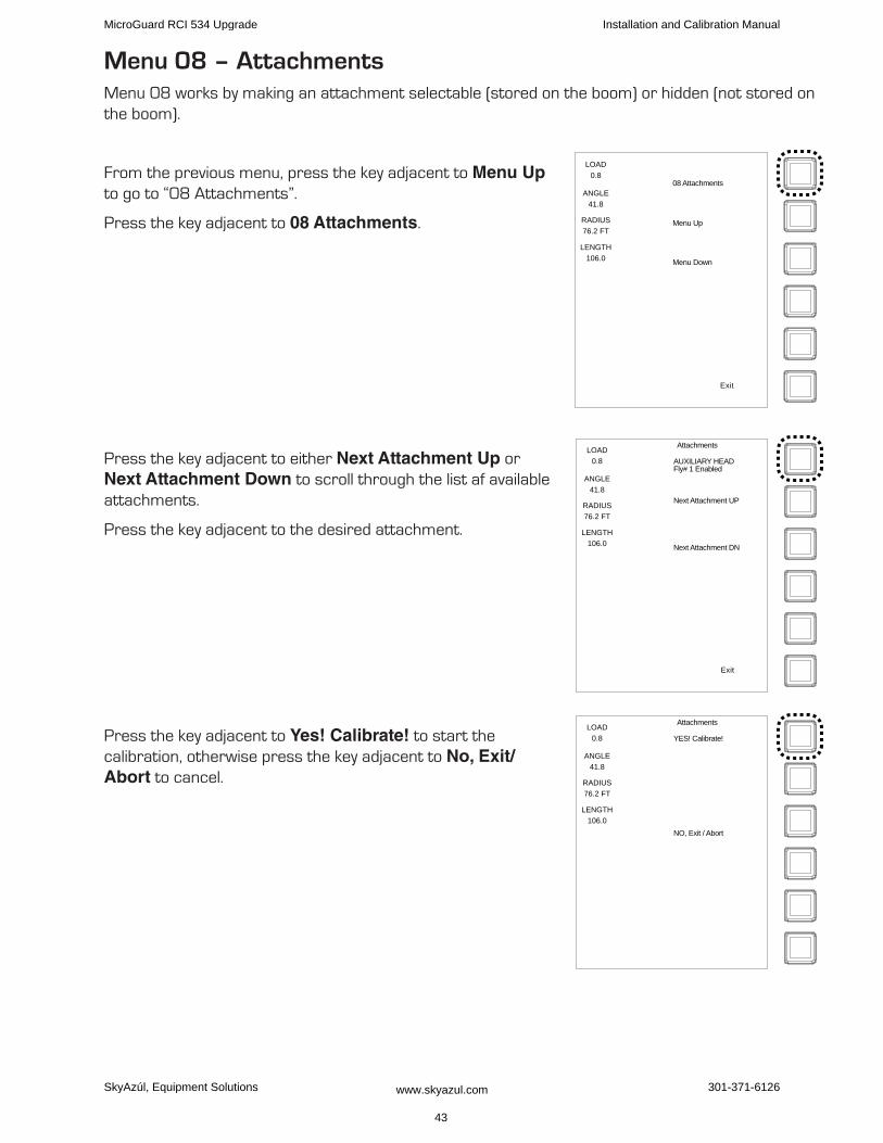
Menu 08 – AttachmentsMenu 08 works by making an attachment selectable (stored on the boom) or hidden (not stored on the boom).
From the previous menu, press the key adjacent to Menu Up to go to “08 Attachments”.
Press the key adjacent to 08 Attachments.
Press the key adjacent to either Next Attachment Up or Next Attachment Down to scroll through the list af available attachments.
Press the key adjacent to the desired attachment.
Press the key adjacent to Yes! Calibrate! to start the calibration, otherwise press the key adjacent to No, Exit/Abort to cancel.
LOAD
0.8
ANGLE
41.8
RADIUS
76.2 FT
LENGTH
106.0
08 Attachments
Menu Up
Menu Down
Exit
LOAD
0.8
ANGLE
41.8
RADIUS
76.2 FT
LENGTH
106.0
Attachments
AUXILIARY HEADFly# 1 Enabled
Next Attachment DN
Next Attachment UP
Exit
LOAD
0.8
ANGLE
41.8
RADIUS
76.2 FT
LENGTH
106.0
Attachments
YES! Calibrate!
NO, Exit / Abort
MicroGuard RCI 534 Upgrade Installation and Calibration Manual
SkyAzúl, Equipment Solutions www.skyazul.com 43
301-371-6126
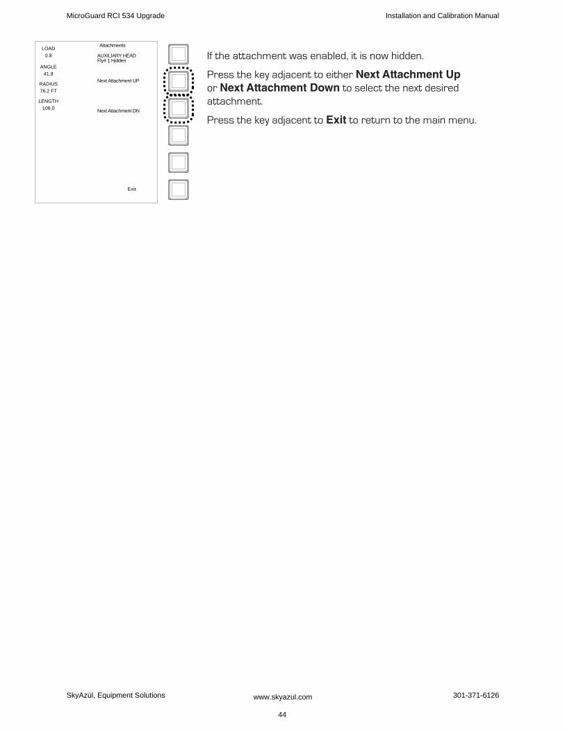
If the attachment was enabled, it is now hidden.
Press the key adjacent to either Next Attachment Up or Next Attachment Down to select the next desired attachment.
Press the key adjacent to Exit to return to the main menu.
LOAD
0.8
ANGLE
41.8
RADIUS
76.2 FT
LENGTH
106.0
Attachments
AUXILIARY HEADFly# 1 Hidden
Next Attachment DN
Next Attachment UP
Exit
MicroGuard RCI 534 Upgrade Installation and Calibration Manual
SkyAzúl, Equipment Solutions www.skyazul.com 44
301-371-6126
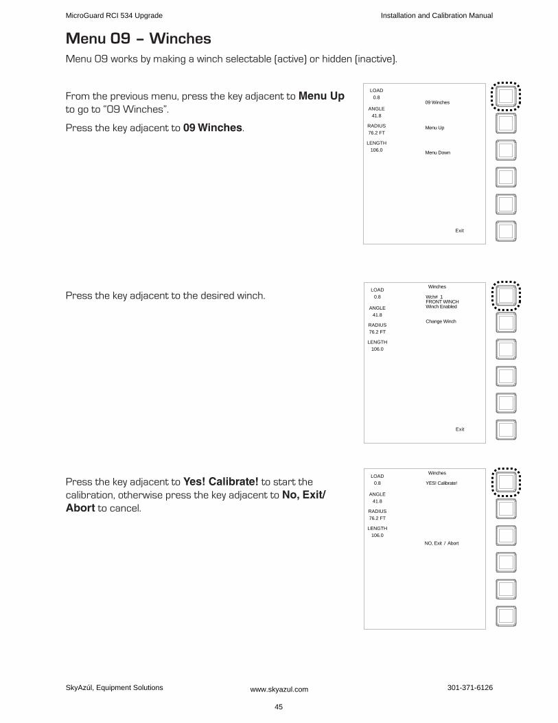
Menu 09 – WinchesMenu 09 works by making a winch selectable (active) or hidden (inactive).
From the previous menu, press the key adjacent to Menu Up to go to “09 Winches”.
Press the key adjacent to 09 Winches.
Press the key adjacent to the desired winch.
Press the key adjacent to Yes! Calibrate! to start the calibration, otherwise press the key adjacent to No, Exit/Abort to cancel.
LOAD
0.8
ANGLE
41.8
RADIUS
76.2 FT
LENGTH
106.0
09 Winches
Menu Up
Menu Down
Exit
LOAD
0.8
ANGLE
41.8
RADIUS
76.2 FT
LENGTH
106.0
Winches
Change Winch
Wch# 1FRONT WINCHWinch Enabled
Exit
LOAD
0.8
ANGLE
41.8
RADIUS
76.2 FT
LENGTH
106.0
Winches
NO, Exit / Abort
YES! Calibrate!
MicroGuard RCI 534 Upgrade Installation and Calibration Manual
SkyAzúl, Equipment Solutions www.skyazul.com 45
301-371-6126
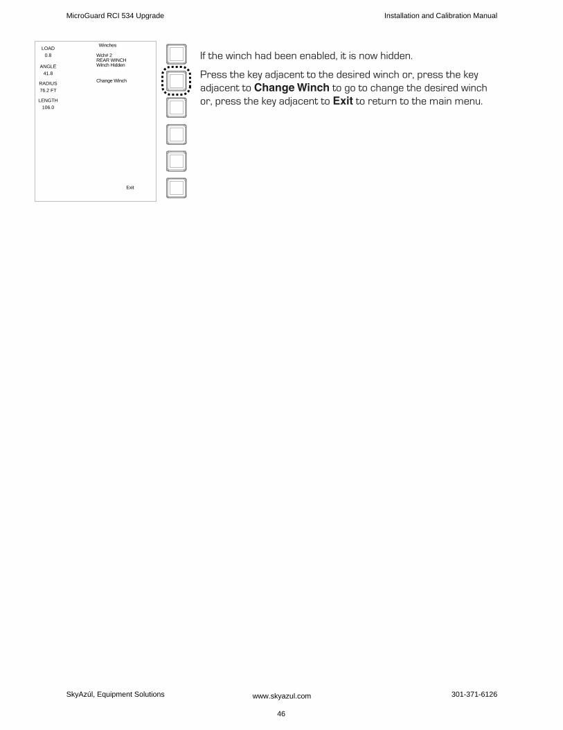
If the winch had been enabled, it is now hidden.
Press the key adjacent to the desired winch or, press the key adjacent to Change Winch to go to change the desired winch or, press the key adjacent to Exit to return to the main menu.
LOAD
0.8
ANGLE
41.8
RADIUS
76.2 FT
LENGTH
106.0
Winches
Exit
Wch# 2REAR WINCHWinch Hidden
Change Winch
MicroGuard RCI 534 Upgrade Installation and Calibration Manual
SkyAzúl, Equipment Solutions www.skyazul.com 46
301-371-6126
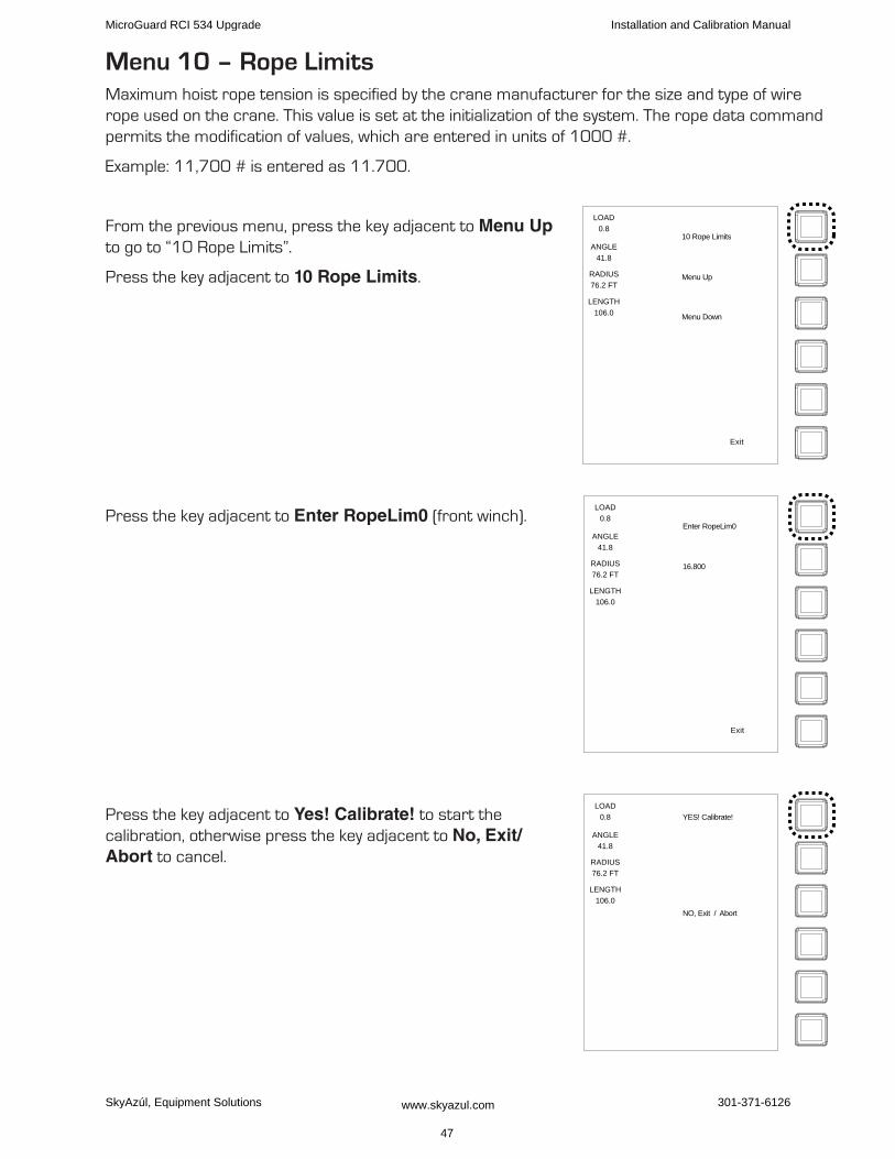
Menu 10 – Rope LimitsMaximum hoist rope tension is specified by the crane manufacturer for the size and type of wire rope used on the crane. This value is set at the initialization of the system. The rope data command permits the modification of values, which are entered in units of 1000 #.
Example: 11,700 # is entered as 11.700.
From the previous menu, press the key adjacent to Menu Up to go to “10 Rope Limits”.
Press the key adjacent to 10 Rope Limits.
Press the key adjacent to Enter RopeLim0 (front winch).
Press the key adjacent to Yes! Calibrate! to start the calibration, otherwise press the key adjacent to No, Exit/Abort to cancel.
LOAD
0.8
ANGLE
41.8
RADIUS
76.2 FT
LENGTH
106.0
10 Rope Limits
Menu Up
Menu Down
Exit
LOAD
0.8
ANGLE
41.8
RADIUS
76.2 FT
LENGTH
106.0
Enter RopeLim0
16.800
Exit
LOAD
0.8
ANGLE
41.8
RADIUS
76.2 FT
LENGTH
106.0
YES! Calibrate!
NO, Exit / Abort
MicroGuard RCI 534 Upgrade Installation and Calibration Manual
SkyAzúl, Equipment Solutions www.skyazul.com 47
301-371-6126
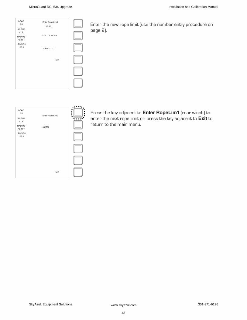
Enter the new rope limit (use the number entry procedure on page 2).
Press the key adjacent to Enter RopeLim1 (rear winch) to enter the next rope limit or, press the key adjacent to Exit to return to the main menu.
LOAD
0.8
ANGLE
41.8
RADIUS
76.2 FT
LENGTH
106.0
Enter Rope Lim0
[ 16.80]
<0> 1 2 3 4 5 6
7 8 9 < . - C
Exit
LOAD
0.8
ANGLE
41.8
RADIUS
76.2 FT
LENGTH
106.0
Enter Rope Lim1
16.800
Exit
MicroGuard RCI 534 Upgrade Installation and Calibration Manual
SkyAzúl, Equipment Solutions www.skyazul.com
48
301-371-6126

Menu 11 – AlarmsDepending on the model of crane being calibrated, the computer can put limits on various functions via alarms.
free Bm Mode• - this mode allows the operator to select the main boom + manual configuration after the manual section (if equipped) is already extended. if the crane being calibrated has Mode A and Mode B selections, this mode must be set to “no.” Damage could result from the wrong selection made.
Area Alarm• - this limit activates the area alarm. Refer to the crane operator’s manual for explanation of the area alarms.
Low Angle Alarm• - some models have engine covers that stand tall and could be damaged by the boom or the boom hoist cylinders. Two alarms are used to warn the operator of the approach to this potential damage; these are swing arc and boom angle. These alarms are preset for:
Low arc = 70° Low ang = 4.5°
Alternate chart• - allows activation of alternate charts, if available, in the applications part of the system chip.
Load scale• - is a small scaling factor to allow load trimming. It should not be altered.
From the previous menu, press the key adjacent to Menu Up to go to “11 Alarms”.
Press the key adjacent to 11 Alarms.
The display will show “Free Boom Mode? (y/n)”.
Press the key adjacent to Free Boom Mode? (y/n) to toggle between “Yes” and “No”..
Press the key adjacent to Exit to go to the next alarm.
The display will show the next alarm, enable or disable the alarm as desired.
LOAD
0.8
ANGLE
41.8
RADIUS
76.2 FT
LENGTH
106.0
11 Alarms
Menu Up
Menu Down
Exit
LOAD
0.8
ANGLE
41.8
RADIUS
76.2 FT
LENGTH
106.0
Alarms
Free Bm Mode y/n YES
Exit
MicroGuard RCI 534 Upgrade Installation and Calibration Manual
SkyAzúl, Equipment Solutions www.skyazul.com 49
301-371-6126
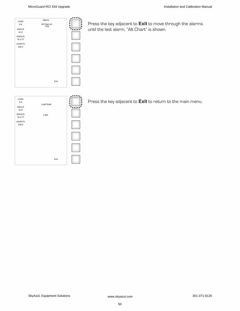
Press the key adjacent to Exit to move through the alarms until the last alarm, “Alt Chart” is shown.
Press the key adjacent to Exit to return to the main menu.
LOAD
0.8
ANGLE
41.8
RADIUS
76.2 FT
LENGTH
106.0
Alarms
Alt Chart y/n YES
Exit
LOAD
0.8
ANGLE
41.8
RADIUS
76.2 FT
LENGTH
106.0
Load Scale
1.000
Exit
MicroGuard RCI 534 Upgrade Installation and Calibration Manual
SkyAzúl, Equipment Solutions www.skyazul.com 50
301-371-6126
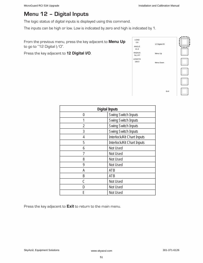
Menu 12 – Digital InputsThe logic status of digital inputs is displayed using this command.
The inputs can be high or low. Low is indicated by zero and high is indicated by 1.
From the previous menu, press the key adjacent to Menu Up to go to “12 Digital I/O”.
Press the key adjacent to 12 Digital I/O.
Digital Inputs0 Swing Switch Inputs1 Swing Switch Inputs2 Swing Switch Inputs3 Swing Switch Inputs4 Interlock/Alt Chart Inputs5 Interlock/Alt Chart Inputs6 Not Used7 Not Used8 Not Used9 Not UsedA ATBB ATBC Not UsedD Not UsedE Not Used
Press the key adjacent to Exit to return to the main menu.
LOAD
0.8
ANGLE
41.8
RADIUS
76.2 FT
LENGTH
106.0
12 Digital I/O
Menu Up
Menu Down
Exit
MicroGuard RCI 534 Upgrade Installation and Calibration Manual
SkyAzúl, Equipment Solutions www.skyazul.com 51
301-371-6126
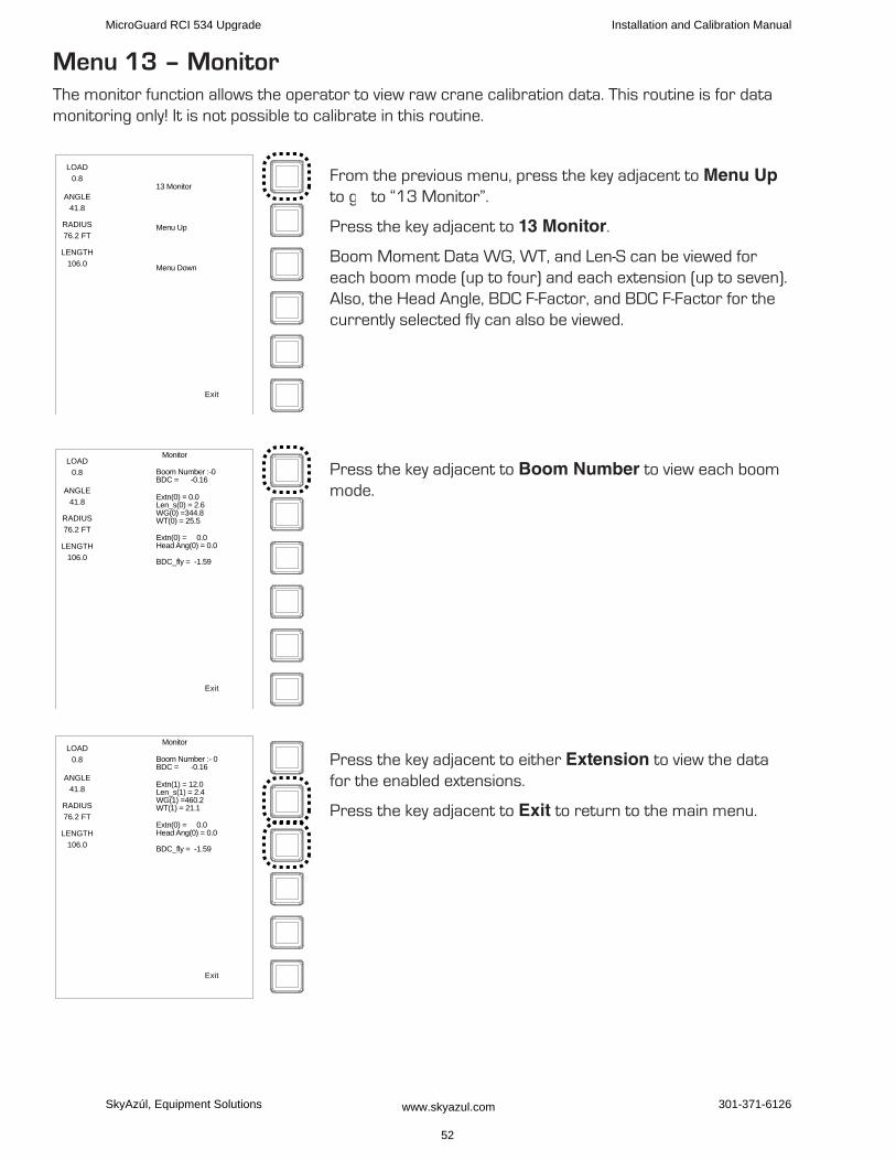
Menu 13 – MonitorThe monitor function allows the operator to view raw crane calibration data. This routine is for data monitoring only! It is not possible to calibrate in this routine.
From the previous menu, press the key adjacent to Menu Up to g to “13 Monitor”.
Press the key adjacent to 13 Monitor.
Boom Moment Data WG, WT, and Len-S can be viewed for each boom mode (up to four) and each extension (up to seven). Also, the Head Angle, BDC F-Factor, and BDC F-Factor for the currently selected fly can also be viewed.
Press the key adjacent to Boom Number to view each boom mode.
Press the key adjacent to either Extension to view the data for the enabled extensions.
Press the key adjacent to Exit to return to the main menu.
LOAD
0.8
ANGLE
41.8
RADIUS
76.2 FT
LENGTH
106.0
13 Monitor
Menu Up
Menu Down
Exit
LOAD
0.8
ANGLE
41.8
RADIUS
76.2 FT
LENGTH
106.0
Boom Number :-0BDC = -0.16
Monitor
Extn(0) = 0.0Len_s(0) = 2.6WG(0) =344.8WT(0) = 25.5
Extn(0) = 0.0Head Ang(0) = 0.0
BDC_fly = -1.59
Exit
LOAD
0.8
ANGLE
41.8
RADIUS
76.2 FT
LENGTH
106.0
Boom Number :- 0BDC = -0.16
Monitor
Extn(1) = 12.0Len_s(1) = 2.4WG(1) =460.2WT(1) = 21.1
Extn(0) = 0.0Head Ang(0) = 0.0
BDC_fly = -1.59
Exit
MicroGuard RCI 534 Upgrade Installation and Calibration Manual
SkyAzúl, Equipment Solutions www.skyazul.com 52
301-371-6126

Menu 15 – PressureMenu 15 is also a monitor function. This function allows the operator to view information on the system pressure channels.
From the previous menu, press the key adjacent to Menu Up to go to “15 Pressure”.
Press the key adjacent to 15 Pressure.
The following information is displayed:
Current System Temperature•
Piston Side Hydraulic Pressure (actual PSI reading)•
Rod Side Hydraulic Pressure (actual PSI reading)•
Nett Pressure (the difference between piston and rod side pressures scaled by the cylinder•geometry).
Press the key adjacent to Exit to return to the main menu.
LOAD
0.8
ANGLE
41.8
RADIUS
76.2 FT
LENGTH
106.0
15 Pressure
Menu Up
Menu Down
Exit
MicroGuard RCI 534 Upgrade Installation and Calibration Manual
SkyAzúl, Equipment Solutions www.skyazul.com
53
301-371-6126

Appendix A
glossary of terms
Term DefinitionAbort Stops data entry into the system before the entry process is finalized.Alarm A visual or audible warning signal.Amplifier Increases - example: a pressure transducer in the millivolt range is amplified up to ten
volts).Amplifier gain The factor used to express the level of amplification.Analog A mechanism in which data is represented by continuously variable physical quantities.Angle sensor A device that measures the angle of the boom relative to the horizon.Annular Relating to, or forming a ring (e.g. the pressure around the rod of a boom hoist cylinder).Annular gain The factor used to modify the pressure signal from the rod side of the boom hoist
cylinder based on the difference in areas of the rod and the bore.Back-up A copy of data saved in a separate computer chip.Boom deflection The change of radius due to the bending of a boom under load.Boom moment The turning moment around the boom pivot caused by the moment of the unladen boom.Bore The piston side of a boom hoist cylinder.Calibration The adjustment of the graduation of sensors.Capacity chart A table, supplied by the crane manufacturer, showing the specifications and ratings for
each individual crane.Center of gravity The point at which the entire weight of a body may be considered as concentrated, so
that if supported at this point, the body would remain in equilibrium in any position.Commissioning Preparing to be put into service.Configuration The position of the crane supporting appendages and all lifting elements of a crane.Cursor A pointer on a display that indicates where data is to be entered.Data Factual information used as a basis for calculation.Deduct A reduction in rated capacity for an unused, stowed, or erected attachment.Deflection The bending of a boom or the stretching of pendant lines within the elastic limits of the
boom or pendants.Digital Operating with numbers shown as digits.Digital inputs Computer - usually controlled by external on/off switches.Direction The course on which the upper section (superstructure) of a crane rotates.Duty A working configuration of a crane usually found in a single column of a capacity chart.Eeprom Electrically erasable and programmable “read only” memory (rom).Elastic Capable of recovering size or shape after expansion. Erected attachment An attachment on the main boom in working (not stowed) position.Extension sensor A device that measures the extension of the telescoping sections of a boom.Fly/jib An attachment connected by one edge to a crane boom (e.g. A lattice fly, or jib).Force Energy exerted, in this case to support the weight of an object.Geometry A branch of mathematics addressed to the measurement and relationships of points,
lines, angles, surfaces, and solids.Graduated Marked with degrees of measurement.
MicroGuard RCI 534 Upgrade Installation and Calibration Manual
SkyAzúl, Equipment Solutions www.skyazul.com 54
301-371-6126

Term DefinitionHeight The vertical distance from the ground to the tip of the boom or attachment.Hite An abbreviation of the word height. The height of the boom pivot above ground level.Horizontal Parallel to the horizon.Hydraulic cranes Using the pressure of oil for operation.Increment The action of increasing a number or value.Initializes Erases all data from memory prior to a new calibration.Integrated circuits A tiny complex of electronic components and connections on a small slice of material
(such as silicon).Measure height To determine the vertical distance from below the boom pivot to the ground. Radius
measurements are made from these points when calibrating.Microprocessor A computer processor contained on an integrated chip.Millivolt One thousandth of a volt.Moment The product of force and distance in relation to a particular axis or point.Out of duty A point that is either longer than the longest permitted radius or lower than the lowest
permitted angle on a capacity chart.Outrigger A mechanical device that projects from the main structure of the crane to provide
additional stability or support.Personality A computer chip storing active calibration data.Pressure Hydraulic pressure in the boom hoist cylinder.Radius The horizontal distance from the centerline of rotation to the center of the hook.Rated capacity The lifting capacity of a crane, as determined by the manufacturer’s published capacity
chart.Rated capacity The load that a crane can safely support, based on factors such as strength, stability,
and rating.Rating A factor determined by legislation that limits the action of a crane in a lifting operation.
Usually expressed as a percentage of strength or stability.Restore Move data from a back-up chip to the personality “a” active chip.Rom “Read only” memory. Data can be read but not changed after programming.Rope limit The maximum permitted single line pull determined by the construction and diameter of a
wire rope.Save Move data from the working personality to a ‘write protected’ area of memory.Scale The use of a factor to set the scaling of analog sensors.Scale Something graduated when used in measurement.Sensitivity The capacity of a sensor to respond to physical stimulus.Sensor A device that responds to a physical stimulus and transmits a resulting impulse.Sheave A grooved wheel or pulley.Slew offset The horizontal distance from the boom pivot to the center of rotation.Span An extent or spread between two limits.Span The calibration of an analog sensor between zero and maximum span.Stowed attachment An attachment usually stored in an inactive position on the main boom.Superstructure The structural part of a crane above the carrier, usually rotating.Swing The rotation of a crane upper around its centerline.
MicroGuard RCI 534 Upgrade Installation and Calibration Manual
SkyAzúl, Equipment Solutions www.skyazul.com
55
301-371-6126
Term DefinitionSwl (%swl) Percentage of ‘safe working load.’ The proportion of the crane capacity that is being
utilized at any one time and expressed as a percentage of rated capacity.Transducer A device that is actuated by energy from one system and converts this energy to another
form for use by a different system (as a loudspeaker that is actuated by electrical signals and supplies acoustic power).
Tx.0 The piston side pressure transducer.Tx.1 The rod side pressure transducer.Unladen A boom that has no additional stowed or erected attachments and is not supporting a
load.Volt Unit of electrical potential difference and electromotive force.Weight The amount that a body weighs.Write protected An area of memory in a computer that cannot be accessed by a microprocessor for data
entry or change.Zero The zero point on a graduated scale.
MicroGuard RCI 534 Upgrade Installation and Calibration Manual
SkyAzúl, Equipment Solutions www.skyazul.com 56
301-371-6126


SkyAzúl, Equipment Solutions www.skyazul.com 301-371-6126
SkyAzúl, Inc. 16 Walnut Street Middletown, MD 21769 Phone 301-371-6126 Fax 301-371-0029 [email protected] www.skyazul.com