Embed Size (px)
Citation preview

Q5X Laser Measurement Sensor with IO-Link
Instruction Manual
Original Instructions208794 Rev. H4 November 2021© Banner Engineering Corp. All rights reserved
208794
Contents
1 Product Description ..................................................................................................................................................... 41.1 Models ..............................................................................................................................................................................................41.2 Overview ......................................................................................................................................................................................... 41.3 Class 2 Laser Description and Safety Information ...........................................................................................................................41.4 Features ..........................................................................................................................................................................................5
1.4.1 Display and Indicators .............................................................................................................................................................. 61.4.2 Buttons .................................................................................................................................................................................... 6
2 Installation ......................................................................................................................................................................72.1 Sensor Orientation for the Triangulation Models ..............................................................................................................................72.2 Mount the Device ............................................................................................................................................................................ 72.3 Wiring Diagram ................................................................................................................................................................................ 82.4 Cleaning and Maintenance ............................................................................................................................................................. 82.5 Connecting to RSD1 ....................................................................................................................................................................... 92.6 Button Map from RSD1 to Sensor ..................................................................................................................................................10
3 Sensor Programming ................................................................................................................................................. 113.1 Channel 1 and Channel 2 (CH1/CH2) ...........................................................................................................................................113.2 Setup Mode ...................................................................................................................................................................................11
3.2.1 Output ....................................................................................................................................................................................143.2.2 TEACH Mode ........................................................................................................................................................................ 143.2.3 Adaptive Tracking ..................................................................................................................................................................143.2.4 Window Size ..........................................................................................................................................................................153.2.5 Response Speed ...................................................................................................................................................................153.2.6 Gain and Sensitivity ...............................................................................................................................................................163.2.7 Output Timing Delays ............................................................................................................................................................ 163.2.8 Hysteresis and .......................................................................................................................................................................173.2.9 Zero Reference Location ....................................................................................................................................................... 183.2.10 Shift the Zero Reference Location after a TEACH .............................................................................................................. 193.2.11 Offset ...................................................................................................................................................................................193.2.12 Display View ........................................................................................................................................................................ 203.2.13 Units .................................................................................................................................................................................... 203.2.14 Output Type Polarity ............................................................................................................................................................203.2.15 Exit Setup Mode .................................................................................................................................................................. 203.2.16 Reset to Factory Defaults .................................................................................................................................................... 20
3.3 Manual Adjustments ......................................................................................................................................................................213.4 Remote Input .................................................................................................................................................................................21
3.4.1 Select the TEACH Mode Using the Remote Input .................................................................................................................223.4.2 Reset to Factory Defaults Using the Remote Input ............................................................................................................... 23
3.5 Locking and Unlocking the Sensor Buttons ................................................................................................................................... 233.6 TEACH Procedures .......................................................................................................................................................................24
3.6.1 Two-Point Static Background Suppression ........................................................................................................................... 243.6.2 Dynamic Background Suppression ........................................................................................................................................ 253.6.3 One-Point Window (Foreground Suppression) ......................................................................................................................273.6.4 One-Point Background Suppression ..................................................................................................................................... 283.6.5 Dual (Intensity + Distance) .................................................................................................................................................... 30
3.7 Pulse Frequency Modulation (PFM) Output ..................................................................................................................................313.8 Sync Master/Slave ........................................................................................................................................................................ 31
4 IO-Link Interface .......................................................................................................................................................... 325 Specifications ............................................................................................................................................................. 33
5.1 Specifications .................................................................................................................................................................................335.2 Dimensions .................................................................................................................................................................................... 355.3 Performance Curves ...................................................................................................................................................................... 35
6 Additional Information ............................................................................................................................................... 386.1 Dual (Intensity + Distance) Mode ...................................................................................................................................................386.2 Dual Mode Reference Surface Considerations ..............................................................................................................................386.3 Dual Mode Considerations for Clear and Transparent Object Detection ......................................................................................396.4 Abbreviations ................................................................................................................................................................................ 40
7 Accessories ..................................................................................................................................................................437.1 Cordsets .........................................................................................................................................................................................437.2 Brackets ......................................................................................................................................................................................... 437.3 Reference Targets ........................................................................................................................................................................ 447.4 RSD1 Remote Display ................................................................................................................................................................... 44
8 Product Support and Maintenance ........................................................................................................................... 458.1 Troubleshooting ............................................................................................................................................................................ 45
Q5X Laser Measurement Sensor with IO-Link

8.2 Contact Us ..................................................................................................................................................................................... 458.3 Banner Engineering Corp. Limited Warranty ................................................................................................................................ 45
Q5X Laser Measurement Sensor with IO-Link
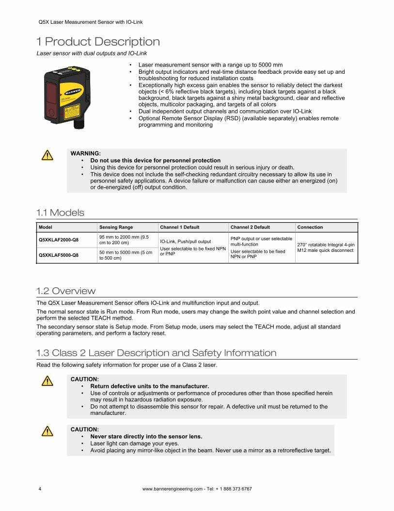
1 Product DescriptionLaser sensor with dual outputs and IO-Link
• Laser measurement sensor with a range up to 5000 mm• Bright output indicators and real-time distance feedback provide easy set up and
troubleshooting for reduced installation costs• Exceptionally high excess gain enables the sensor to reliably detect the darkest
objects (< 6% reflective black targets), including black targets against a blackbackground, black targets against a shiny metal background, clear and reflectiveobjects, multicolor packaging, and targets of all colors
• Dual independent output channels and communication over IO-Link• Optional Remote Sensor Display (RSD) (available separately) enables remote
programming and monitoring
WARNING:• Do not use this device for personnel protection• Using this device for personnel protection could result in serious injury or death.• This device does not include the self-checking redundant circuitry necessary to allow its use in
personnel safety applications. A device failure or malfunction can cause either an energized (on)or de-energized (off) output condition.
1.1 ModelsModel Sensing Range Channel 1 Default Channel 2 Default Connection
Q5XKLAF2000-Q8 95 mm to 2000 mm (9.5cm to 200 cm) IO-Link, Push/pull output
User selectable to be fixed NPNor PNP
PNP output or user selectablemulti-functionUser selectable to be fixedNPN or PNP
270° rotatable Integral 4-pinM12 male quick disconnect
Q5XKLAF5000-Q8 50 mm to 5000 mm (5 cmto 500 cm)
1.2 OverviewThe Q5X Laser Measurement Sensor offers IO-Link and multifunction input and output.The normal sensor state is Run mode. From Run mode, users may change the switch point value and channel selection andperform the selected TEACH method.The secondary sensor state is Setup mode. From Setup mode, users may select the TEACH mode, adjust all standardoperating parameters, and perform a factory reset.
1.3 Class 2 Laser Description and Safety InformationRead the following safety information for proper use of a Class 2 laser.
CAUTION:• Return defective units to the manufacturer.• Use of controls or adjustments or performance of procedures other than those specified herein
may result in hazardous radiation exposure.• Do not attempt to disassemble this sensor for repair. A defective unit must be returned to the
manufacturer.
CAUTION:• Never stare directly into the sensor lens.• Laser light can damage your eyes.• Avoid placing any mirror-like object in the beam. Never use a mirror as a retroreflective target.
Q5X Laser Measurement Sensor with IO-Link
4 www.bannerengineering.com - Tel: + 1 888 373 6767
For Safe Laser Use - Class 2 Lasers• Do not stare at the laser.• Do not point the laser at a person’s eye.• Mount open laser beam paths either above or below eye level, where practical.• Terminate the beam emitted by the laser product at the end of its useful path.
Class 2 lasers are lasers that emit visible radiation in the wavelength range from 400 nm to 700 nm, where eye protection isnormally afforded by aversion responses, including the blink reflex. This reaction may be expected to provide adequateprotection under reasonably foreseeable conditions of operation, including the use of optical instruments for intrabeamviewing.Low-power lasers are, by definition, incapable of causing eye injury within the duration of a blink (aversion response) of 0.25seconds. They also must emit only visible wavelengths (400 to 700 nm). Therefore, an ocular hazard may exist only ifindividuals overcome their natural aversion to bright light and stare directly into the laser beam.
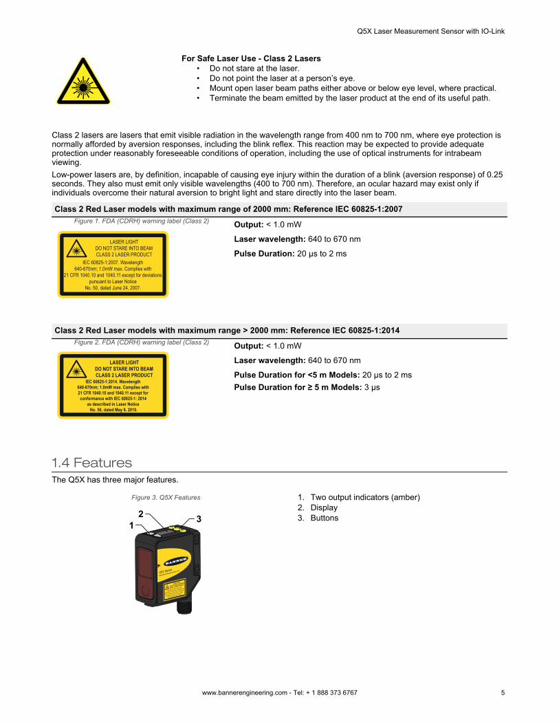
Class 2 Red Laser models with maximum range of 2000 mm: Reference IEC 60825-1:2007Figure 1. FDA (CDRH) warning label (Class 2)
LASER LIGHT DO NOT STARE INTO BEAM CLASS 2 LASER PRODUCT
IEC 60825-1:2007. Wavelength 640-670nm; 1.0mW max. Complies with
21 CFR 1040.10 and 1040.11 except for deviations pursuant to Laser Notice
No. 50, dated June 24, 2007.
Output: < 1.0 mW
Laser wavelength: 640 to 670 nm
Pulse Duration: 20 µs to 2 ms
Class 2 Red Laser models with maximum range > 2000 mm: Reference IEC 60825-1:2014Figure 2. FDA (CDRH) warning label (Class 2)
LASER LIGHT DO NOT STARE INTO BEAM CLASS 2 LASER PRODUCT
IEC 60825-1:2014. Wavelength 640-670nm; 1.0mW max. Complies with 21 CFR 1040.10 and 1040.11 except forconformance with IEC 60825-1: 2014
as described in Laser Notice No. 56, dated May 8, 2019.
Output: < 1.0 mW
Laser wavelength: 640 to 670 nm
Pulse Duration for <5 m Models: 20 µs to 2 msPulse Duration for ≥ 5 m Models: 3 µs
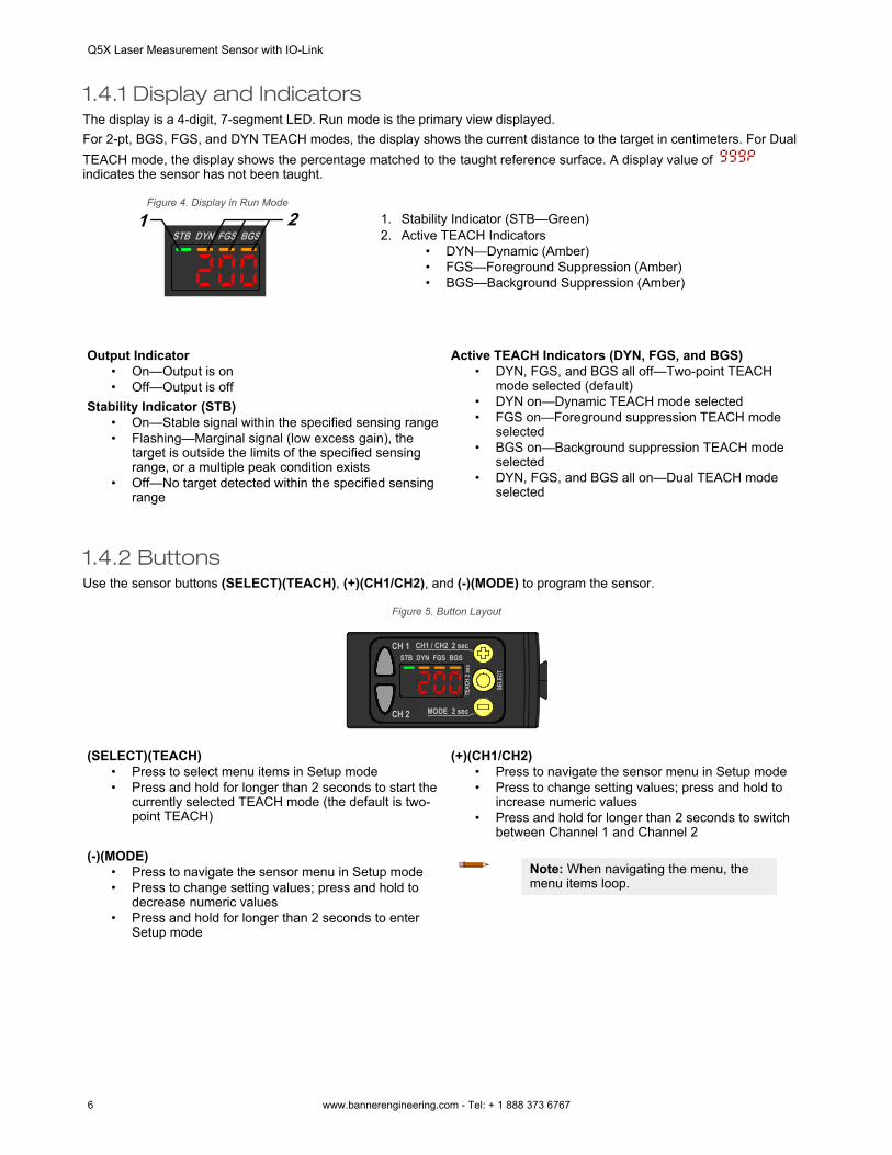
1.4 FeaturesThe Q5X has three major features.
Figure 3. Q5X Features
12 3
1. Two output indicators (amber)2. Display3. Buttons
Q5X Laser Measurement Sensor with IO-Link
www.bannerengineering.com - Tel: + 1 888 373 6767 5
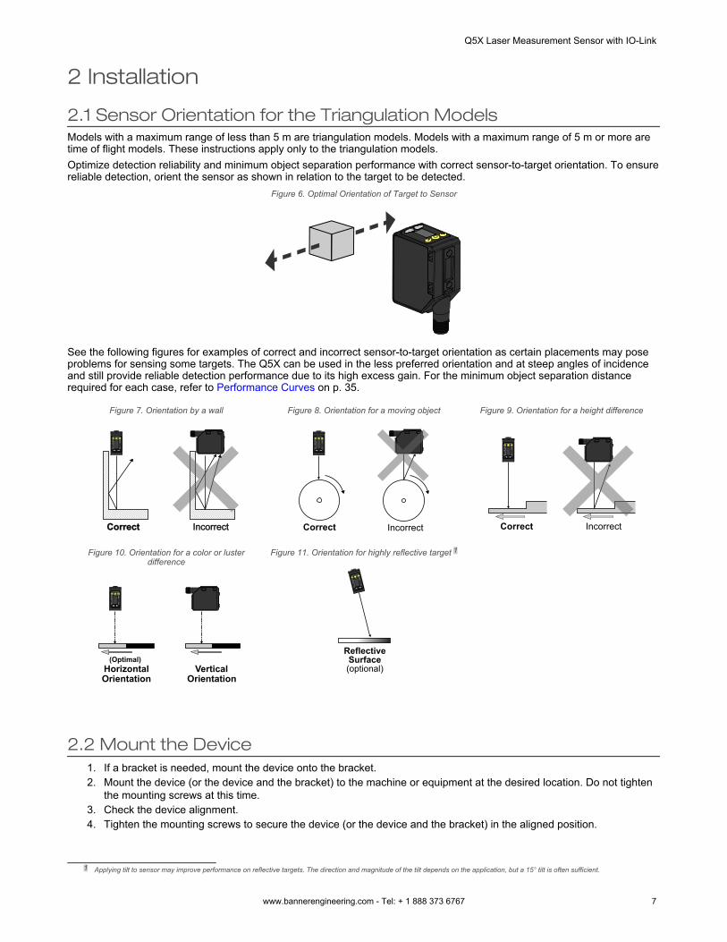
1.4.1 Display and IndicatorsThe display is a 4-digit, 7-segment LED. Run mode is the primary view displayed.For 2-pt, BGS, FGS, and DYN TEACH modes, the display shows the current distance to the target in centimeters. For DualTEACH mode, the display shows the percentage matched to the taught reference surface. A display value of indicates the sensor has not been taught.
Figure 4. Display in Run Mode
STB DYN FGS BGS1 2 1. Stability Indicator (STB—Green)
2. Active TEACH Indicators• DYN—Dynamic (Amber)• FGS—Foreground Suppression (Amber)• BGS—Background Suppression (Amber)
Output Indicator• On—Output is on• Off—Output is off
Stability Indicator (STB)• On—Stable signal within the specified sensing range• Flashing—Marginal signal (low excess gain), the
target is outside the limits of the specified sensingrange, or a multiple peak condition exists
• Off—No target detected within the specified sensingrange
Active TEACH Indicators (DYN, FGS, and BGS)• DYN, FGS, and BGS all off—Two-point TEACH
mode selected (default)• DYN on—Dynamic TEACH mode selected• FGS on—Foreground suppression TEACH mode
selected• BGS on—Background suppression TEACH mode
selected• DYN, FGS, and BGS all on—Dual TEACH mode
selected
1.4.2 ButtonsUse the sensor buttons (SELECT)(TEACH), (+)(CH1/CH2), and (-)(MODE) to program the sensor.
Figure 5. Button Layout
(SELECT)(TEACH)• Press to select menu items in Setup mode• Press and hold for longer than 2 seconds to start the
currently selected TEACH mode (the default is two-point TEACH)
(+)(CH1/CH2)• Press to navigate the sensor menu in Setup mode• Press to change setting values; press and hold to
increase numeric values• Press and hold for longer than 2 seconds to switch
between Channel 1 and Channel 2
(-)(MODE)• Press to navigate the sensor menu in Setup mode• Press to change setting values; press and hold to
decrease numeric values• Press and hold for longer than 2 seconds to enter
Setup mode
Note: When navigating the menu, themenu items loop.
Q5X Laser Measurement Sensor with IO-Link
6 www.bannerengineering.com - Tel: + 1 888 373 6767
2 Installation
2.1 Sensor Orientation for the Triangulation ModelsModels with a maximum range of less than 5 m are triangulation models. Models with a maximum range of 5 m or more aretime of flight models. These instructions apply only to the triangulation models.Optimize detection reliability and minimum object separation performance with correct sensor-to-target orientation. To ensurereliable detection, orient the sensor as shown in relation to the target to be detected.
Figure 6. Optimal Orientation of Target to Sensor
See the following figures for examples of correct and incorrect sensor-to-target orientation as certain placements may poseproblems for sensing some targets. The Q5X can be used in the less preferred orientation and at steep angles of incidenceand still provide reliable detection performance due to its high excess gain. For the minimum object separation distancerequired for each case, refer to Performance Curves on p. 35.
Figure 7. Orientation by a wall
IncorrectCorrectCC
Figure 8. Orientation for a moving object
CC
IncorrectCorrect
Figure 9. Orientation for a height difference
CC
IncorrectCorrect
Figure 10. Orientation for a color or lusterdifference
Horizontal Orientation
Vertical Orientation
(Optimal)
CC
Figure 11. Orientation for highly reflective target 1
ReflectiveSurface (optional)
2.2 Mount the Device1. If a bracket is needed, mount the device onto the bracket.2. Mount the device (or the device and the bracket) to the machine or equipment at the desired location. Do not tighten
the mounting screws at this time.3. Check the device alignment.4. Tighten the mounting screws to secure the device (or the device and the bracket) in the aligned position.
1 Applying tilt to sensor may improve performance on reflective targets. The direction and magnitude of the tilt depends on the application, but a 15° tilt is often sufficient.
Q5X Laser Measurement Sensor with IO-Link
www.bannerengineering.com - Tel: + 1 888 373 6767 7
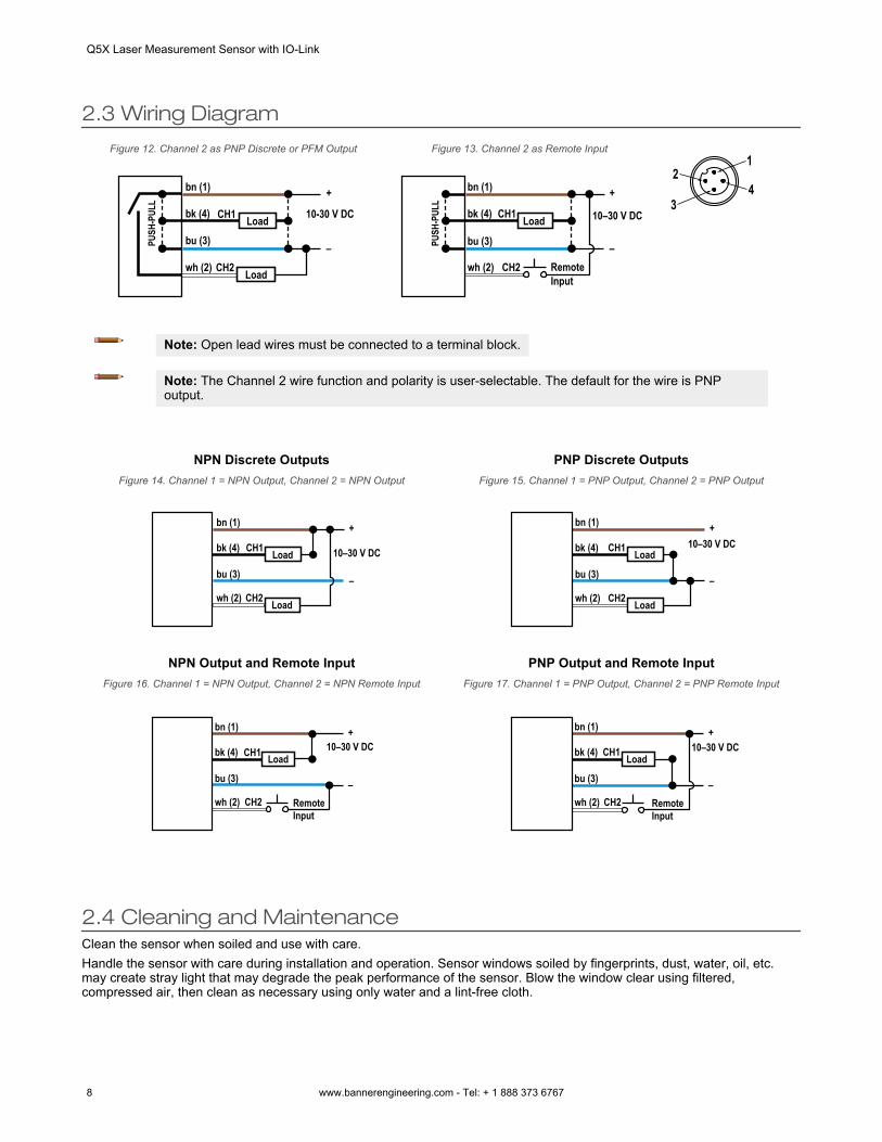
2.3 Wiring Diagram
Figure 12. Channel 2 as PNP Discrete or PFM Output
bk (4)
bn (1)
bu (3)
wh (2)
10-30 V DCCH1
CH2
+
–PUSH
-PUL
L
Load
Load
Figure 13. Channel 2 as Remote Input
bk (4)
bn (1)
bu (3)
wh (2)
10–30 V DCCH1
CH2
+
–PUSH
-PUL
L
Load
RemoteInput
1
43
2
Note: Open lead wires must be connected to a terminal block.
Note: The Channel 2 wire function and polarity is user-selectable. The default for the wire is PNPoutput.
NPN Discrete OutputsFigure 14. Channel 1 = NPN Output, Channel 2 = NPN Output
bk (4)
bn (1)
bu (3)
wh (2)
10–30 V DCCH1
CH2
+
–
Load
Load
PNP Discrete OutputsFigure 15. Channel 1 = PNP Output, Channel 2 = PNP Output
bk (4)
bn (1)
bu (3)
wh (2)
10–30 V DCCH1
CH2
+
–
Load
Load
NPN Output and Remote InputFigure 16. Channel 1 = NPN Output, Channel 2 = NPN Remote Input
bk (4)
bn (1)
bu (3)
wh (2)
10–30 V DCCH1
CH2
+
–
Load
RemoteInput
PNP Output and Remote InputFigure 17. Channel 1 = PNP Output, Channel 2 = PNP Remote Input
bk (4)
bn (1)
bu (3)
wh (2)
10–30 V DCCH1
CH2
+
–
Load
RemoteInput
2.4 Cleaning and MaintenanceClean the sensor when soiled and use with care.Handle the sensor with care during installation and operation. Sensor windows soiled by fingerprints, dust, water, oil, etc.may create stray light that may degrade the peak performance of the sensor. Blow the window clear using filtered,compressed air, then clean as necessary using only water and a lint-free cloth.
Q5X Laser Measurement Sensor with IO-Link
8 www.bannerengineering.com - Tel: + 1 888 373 6767
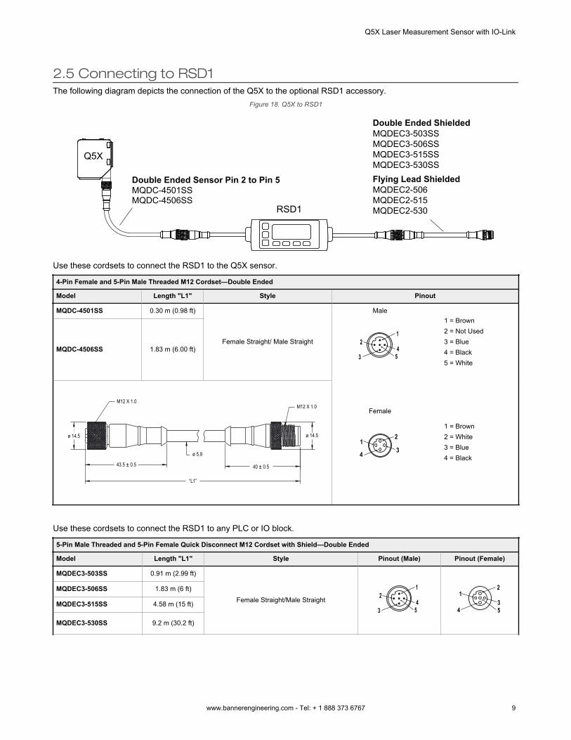
2.5 Connecting to RSD1The following diagram depicts the connection of the Q5X to the optional RSD1 accessory.
Figure 18. Q5X to RSD1
MQDC-4501SS Double Ended Sensor Pin 2 to Pin 5
MQDC-4506SS
MQDEC3-503SS Double Ended Shielded
MQDEC3-506SSMQDEC3-515SSMQDEC3-530SS
MQDEC2-506Flying Lead Shielded
MQDEC2-515MQDEC2-530RSD1
Q5X
Use these cordsets to connect the RSD1 to the Q5X sensor.
4-Pin Female and 5-Pin Male Threaded M12 Cordset—Double Ended
Model Length "L1" Style Pinout
MQDC-4501SS 0.30 m (0.98 ft)
Female Straight/ Male Straight
Male
1
453
2
1 = Brown2 = Not Used3 = Blue4 = Black5 = White
MQDC-4506SS 1.83 m (6.00 ft)
M12 X 1.0
43.5 ± 0.5
“L1”
ø 5.9
M12 X 1.0
ø 14.5 ø 14.5
40 ± 0.5
Female
2
34
1
1 = Brown2 = White3 = Blue4 = Black
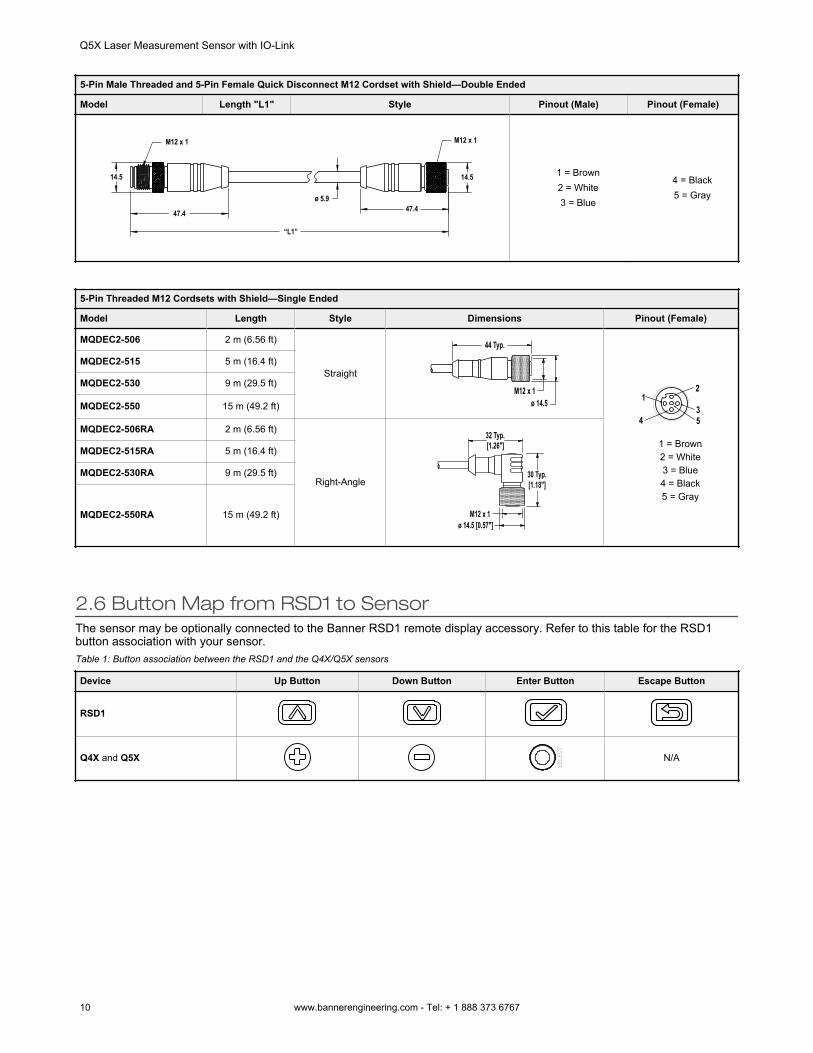
Use these cordsets to connect the RSD1 to any PLC or IO block.
5-Pin Male Threaded and 5-Pin Female Quick Disconnect M12 Cordset with Shield—Double Ended
Model Length "L1" Style Pinout (Male) Pinout (Female)
MQDEC3-503SS 0.91 m (2.99 ft)
Female Straight/Male Straight
1
453
2
2
34
1
5
MQDEC3-506SS 1.83 m (6 ft)
MQDEC3-515SS 4.58 m (15 ft)
MQDEC3-530SS 9.2 m (30.2 ft)
Q5X Laser Measurement Sensor with IO-Link
www.bannerengineering.com - Tel: + 1 888 373 6767 9
5-Pin Male Threaded and 5-Pin Female Quick Disconnect M12 Cordset with Shield—Double Ended
Model Length "L1" Style Pinout (Male) Pinout (Female)
M12 x 1
14.5
ø 5.9
14.5
“L1”
47.4 47.4
M12 x 1
1 = Brown2 = White3 = Blue
4 = Black5 = Gray
5-Pin Threaded M12 Cordsets with Shield—Single Ended
Model Length Style Dimensions Pinout (Female)
MQDEC2-506 2 m (6.56 ft)
Straight
44 Typ.
ø 14.5M12 x 1 2
34
1
5
1 = Brown2 = White3 = Blue4 = Black5 = Gray
MQDEC2-515 5 m (16.4 ft)
MQDEC2-530 9 m (29.5 ft)
MQDEC2-550 15 m (49.2 ft)
MQDEC2-506RA 2 m (6.56 ft)
Right-Angle
32 Typ.[1.26"]
30 Typ.[1.18"]
ø 14.5 [0.57"]M12 x 1
MQDEC2-515RA 5 m (16.4 ft)
MQDEC2-530RA 9 m (29.5 ft)
MQDEC2-550RA 15 m (49.2 ft)
2.6 Button Map from RSD1 to SensorThe sensor may be optionally connected to the Banner RSD1 remote display accessory. Refer to this table for the RSD1button association with your sensor.Table 1: Button association between the RSD1 and the Q4X/Q5X sensors
Device Up Button Down Button Enter Button Escape Button
RSD1
Q4X and Q5X N/A
Q5X Laser Measurement Sensor with IO-Link
10 www.bannerengineering.com - Tel: + 1 888 373 6767
3 Sensor ProgrammingProgram the sensor using the buttons on the sensor or the remote input (limited programming options).In addition to programming the sensor, use the remote input to disable the buttons for security, preventing unauthorized oraccidental programming changes. See Locking and Unlocking the Sensor Buttons on p. 23 for more information.
3.1 Channel 1 and Channel 2 (CH1/CH2)Press CH1/CH2 button to switch between Channel 1 and Channel 2.Within each channel there are options specific to that channel. For settings that are common to both channels, the menus areonly available in Channel 1. The default is Channel 1.To switch between Channel 1 and Channel 2:
1. Press and hold CH1/CH2 for longer than 2 seconds. The current selection displays.2. Press CH1/CH2 again. The new selection flashes slowly.3. Press SELECT to change the Channel and return to Run mode.
Note: If neither SELECT nor CH1/CH2 are pressed after step 2, the new selection flashes slowly for a fewseconds, then flashes quickly and the sensor automatically changes the Channel and returns to Runmode.
3.2 Setup ModeAccess Setup mode and the sensor menu from Run mode by pressing and holding MODE for longer than 2 seconds.
Use and to navigate through the menu. Press SELECT to select a menu option and access the submenus. Use
and to navigate through the submenus. Press SELECT to select a submenu option and return to the top menu, or pressand hold SELECT for longer than 2 seconds to select a submenu option and return immediately to Run mode.
To exit Setup mode and return to Run mode, navigate to and press SELECT.
Note: The number that follows a menu option, for example , indicates the channel that is selected.For menu items without a number (excluding submenu items), these menu options are only available fromChannel 1 and the settings apply to both channels.
Q5X Laser Measurement Sensor with IO-Link
www.bannerengineering.com - Tel: + 1 888 373 6767 11
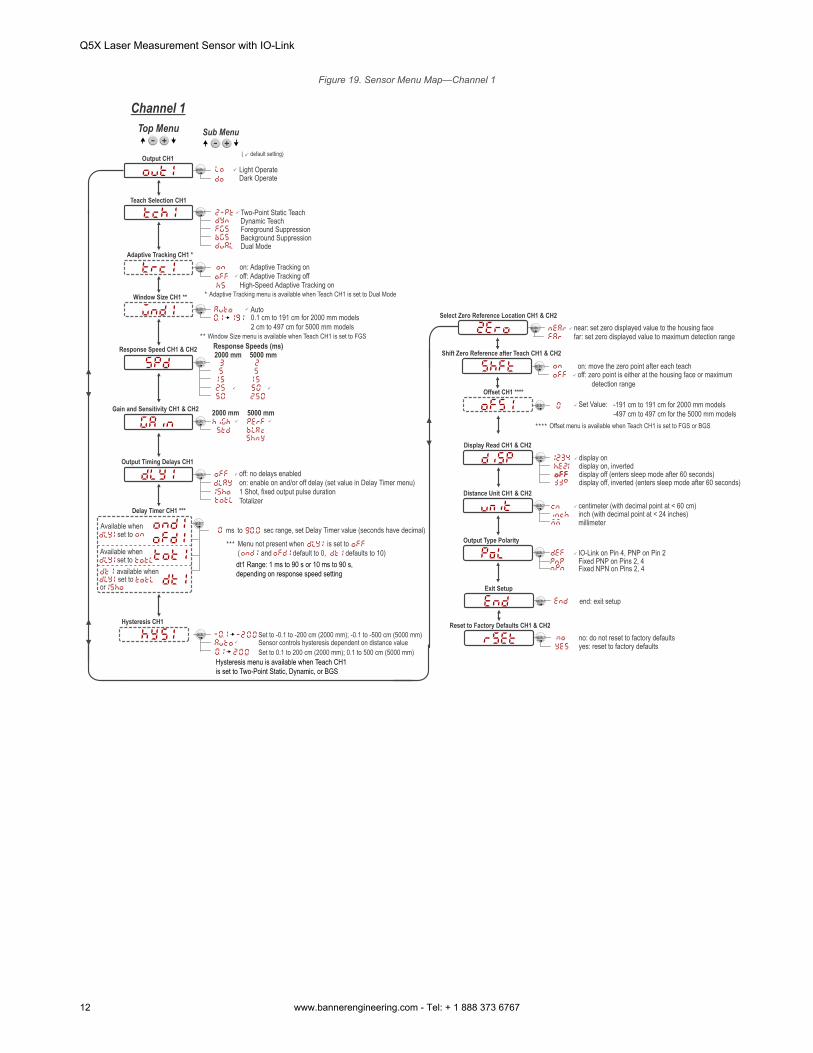
Figure 19. Sensor Menu Map—Channel 1
no: do not reset to factory defaultsyes: reset to factory defaults
Two-Point Static TeachDynamic Teach
Background SuppressionForeground Suppression
Top Menu Sub Menu
off: no delays enabledon: enable on and/or off delay (set value in Delay Timer menu)1 Shot, fixed output pulse durationTotalizer
sec range, set Delay Timer value (seconds have decimal)
display ondisplay on, inverteddisplay off (enters sleep mode after 60 seconds)display off, inverted (enters sleep mode after 60 seconds)
end: exit setup
to
Teach Selection CH1
Output CH1
Window Size CH1 **
Response Speed CH1 & CH2
Output Timing Delays CH1
Delay Timer CH1 ***
Offset CH1 ****
Display Read CH1 & CH2
Exit Setup
Reset to Factory Defaults CH1 & CH2
Available when set to
Available when set to ms
( default setting)
Light OperateDark Operate
Dual Mode
0.1 cm to 191 cm for 2000 mm models2 cm to 497 cm for 5000 mm models
Auto
Adaptive Tracking CH1 *
Menu not present when is set to( and default to 0, defaults to 10)
Set Value:
off: Adaptive Tracking offHigh-Speed Adaptive Tracking on
on: Adaptive Tracking on
Channel 1
Window Size menu is available when Teach CH1 is set to FGS
Adaptive Tracking menu is available when Teach CH1 is set to Dual Mode
Gain and Sensitivity CH1 & CH2
near: set zero displayed value to the housing facefar: set zero displayed value to maximum detection range
Select Zero Reference Location CH1 & CH2
on: move the zero point after each teachoff: zero point is either at the housing face or maximum detection range
Shift Zero Reference after Teach CH1 & CH2
available when set to
or
Offset menu is available when Teach CH1 is set to FGS or BGS
2000 mm
-191 cm to 191 cm for 2000 mm models-497 cm to 497 cm for the 5000 mm models
Set to 0.1 to 200 cm (2000 mm); 0.1 to 500 cm (5000 mm)Sensor controls hysteresis dependent on distance valueSet to -0.1 to -200 cm (2000 mm); -0.1 to -500 cm (5000 mm)
Hysteresis CH1
centimeter (with decimal point at < 60 cm)inch (with decimal point at < 24 inches)
Distance Unit CH1 & CH2
IO-Link on Pin 4, PNP on Pin 2Fixed PNP on Pins 2, 4
Output Type Polarity
Fixed NPN on Pins 2, 4dt1 Range: 1 ms to 90 s or 10 ms to 90 s,depending on response speed setting
Hysteresis menu is available when Teach CH1is set to Two-Point Static, Dynamic, or BGS
Response Speeds (ms)5000 mm
2000 mm 5000 mm
millimeter
Q5X Laser Measurement Sensor with IO-Link
12 www.bannerengineering.com - Tel: + 1 888 373 6767
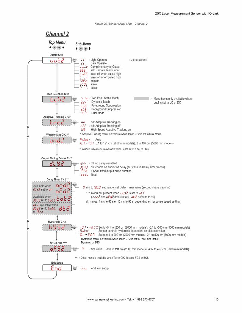
Figure 20. Sensor Menu Map—Channel 2
Two-Point Static TeachDynamic Teach
Background SuppressionForeground Suppression
Top Menu Sub Menu
off: no delays enabledon: enable on and/or off delay (set value in Delay Timer menu)1 Shot, fixed output pulse durationTotal
end: exit setup
Teach Selection CH2
Output CH2
Window Size CH2 **
Output Timing Delays CH2
Offset CH2 ****
Exit Setup
( default setting)Light OperateDark OperateComplimentary to Output 1
Dual ModeAdaptive Tracking CH2 *
off: Adaptive Tracking offHigh-Speed Adaptive Tracking on
on: Adaptive Tracking on
Channel 2
Adaptive Tracking menu is available when Teach CH2 is set to Dual Mode
laser off when pulled highlaser on when pulled high
set: Remote Teach input
masterslavepulse
sec range, set Delay Timer value (seconds have decimal)toms
Menu not present when is set to( and defaults to 0, defaults to 10)
Delay Timer CH2 ***
Available when set to
Available when set to
available when set to
or
Menu items only available when out2 is set to LO or DO
=
Auto
Set Value:
Offset menu is available when Teach CH2 is set to FGS or BGS
-191 to 191 cm (2000 mm models); -497 to 497 cm (5000 mm models)
0.1 to 191 cm (2000 mm models); 2 to 497 cm (5000 mm models)Window Size menu is available when Teach CH2 is set to FGS
Set to 0.1 to 200 cm (2000 mm models); 0.1 to 500 cm (5000 mm models)Sensor controls hysteresis dependent on distance valueSet to -0.1 to -200 cm (2000 mm models); -0.1 to -500 cm (5000 mm models)
Hysteresis CH2
dt1 range: 1 ms to 90 s or 10 ms to 90 s, depending on response speed setting
Hysteresis menu is available when Teach CH2 is set to Two-Point Static, Dynamic, or BGS
Q5X Laser Measurement Sensor with IO-Link
www.bannerengineering.com - Tel: + 1 888 373 6767 13
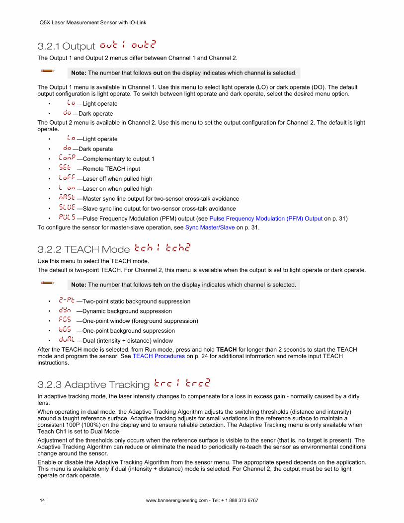
3.2.1 Output The Output 1 and Output 2 menus differ between Channel 1 and Channel 2.
Note: The number that follows out on the display indicates which channel is selected.
The Output 1 menu is available in Channel 1. Use this menu to select light operate (LO) or dark operate (DO). The defaultoutput configuration is light operate. To switch between light operate and dark operate, select the desired menu option.
• —Light operate• —Dark operate
The Output 2 menu is available in Channel 2. Use this menu to set the output configuration for Channel 2. The default is lightoperate.
• —Light operate• —Dark operate• —Complementary to output 1• —Remote TEACH input• —Laser off when pulled high• —Laser on when pulled high• —Master sync line output for two-sensor cross-talk avoidance• —Slave sync line output for two-sensor cross-talk avoidance• —Pulse Frequency Modulation (PFM) output (see Pulse Frequency Modulation (PFM) Output on p. 31)
To configure the sensor for master-slave operation, see Sync Master/Slave on p. 31.
3.2.2 TEACH Mode Use this menu to select the TEACH mode.The default is two-point TEACH. For Channel 2, this menu is available when the output is set to light operate or dark operate.
Note: The number that follows tch on the display indicates which channel is selected.
• —Two-point static background suppression• —Dynamic background suppression• —One-point window (foreground suppression)• —One-point background suppression• —Dual (intensity + distance) window
After the TEACH mode is selected, from Run mode, press and hold TEACH for longer than 2 seconds to start the TEACHmode and program the sensor. See TEACH Procedures on p. 24 for additional information and remote input TEACHinstructions.
3.2.3 Adaptive Tracking In adaptive tracking mode, the laser intensity changes to compensate for a loss in excess gain - normally caused by a dirtylens.When operating in dual mode, the Adaptive Tracking Algorithm adjusts the switching thresholds (distance and intensity)around a taught reference surface. Adaptive tracking adjusts for small variations in the reference surface to maintain aconsistent 100P (100%) on the display and to ensure reliable detection. The Adaptive Tracking menu is only available whenTeach Ch1 is set to Dual Mode.Adjustment of the thresholds only occurs when the reference surface is visible to the senor (that is, no target is present). TheAdaptive Tracking Algorithm can reduce or eliminate the need to periodically re-teach the sensor as environmental conditionschange around the sensor.Enable or disable the Adaptive Tracking Algorithm from the sensor menu. The appropriate speed depends on the application.This menu is available only if dual (intensity + distance) mode is selected. For Channel 2, the output must be set to lightoperate or dark operate.
Q5X Laser Measurement Sensor with IO-Link
14 www.bannerengineering.com - Tel: + 1 888 373 6767
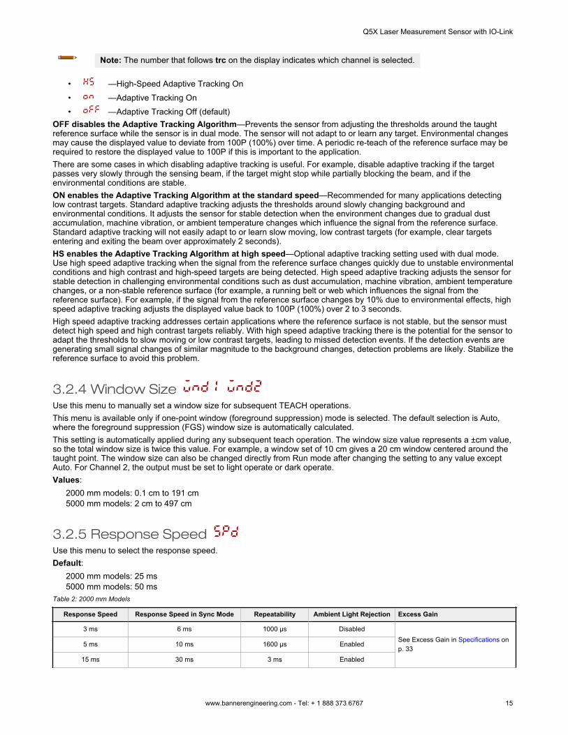
Note: The number that follows trc on the display indicates which channel is selected.
• —High-Speed Adaptive Tracking On• —Adaptive Tracking On• —Adaptive Tracking Off (default)
OFF disables the Adaptive Tracking Algorithm—Prevents the sensor from adjusting the thresholds around the taughtreference surface while the sensor is in dual mode. The sensor will not adapt to or learn any target. Environmental changesmay cause the displayed value to deviate from 100P (100%) over time. A periodic re-teach of the reference surface may berequired to restore the displayed value to 100P if this is important to the application.There are some cases in which disabling adaptive tracking is useful. For example, disable adaptive tracking if the targetpasses very slowly through the sensing beam, if the target might stop while partially blocking the beam, and if theenvironmental conditions are stable.ON enables the Adaptive Tracking Algorithm at the standard speed—Recommended for many applications detectinglow contrast targets. Standard adaptive tracking adjusts the thresholds around slowly changing background andenvironmental conditions. It adjusts the sensor for stable detection when the environment changes due to gradual dustaccumulation, machine vibration, or ambient temperature changes which influence the signal from the reference surface.Standard adaptive tracking will not easily adapt to or learn slow moving, low contrast targets (for example, clear targetsentering and exiting the beam over approximately 2 seconds).HS enables the Adaptive Tracking Algorithm at high speed—Optional adaptive tracking setting used with dual mode.Use high speed adaptive tracking when the signal from the reference surface changes quickly due to unstable environmentalconditions and high contrast and high-speed targets are being detected. High speed adaptive tracking adjusts the sensor forstable detection in challenging environmental conditions such as dust accumulation, machine vibration, ambient temperaturechanges, or a non-stable reference surface (for example, a running belt or web which influences the signal from thereference surface). For example, if the signal from the reference surface changes by 10% due to environmental effects, highspeed adaptive tracking adjusts the displayed value back to 100P (100%) over 2 to 3 seconds.High speed adaptive tracking addresses certain applications where the reference surface is not stable, but the sensor mustdetect high speed and high contrast targets reliably. With high speed adaptive tracking there is the potential for the sensor toadapt the thresholds to slow moving or low contrast targets, leading to missed detection events. If the detection events aregenerating small signal changes of similar magnitude to the background changes, detection problems are likely. Stabilize thereference surface to avoid this problem.
3.2.4 Window Size Use this menu to manually set a window size for subsequent TEACH operations.This menu is available only if one-point window (foreground suppression) mode is selected. The default selection is Auto,where the foreground suppression (FGS) window size is automatically calculated.This setting is automatically applied during any subsequent teach operation. The window size value represents a ±cm value,so the total window size is twice this value. For example, a window set of 10 cm gives a 20 cm window centered around thetaught point. The window size can also be changed directly from Run mode after changing the setting to any value exceptAuto. For Channel 2, the output must be set to light operate or dark operate.Values:
2000 mm models: 0.1 cm to 191 cm5000 mm models: 2 cm to 497 cm
3.2.5 Response Speed Use this menu to select the response speed.Default:
2000 mm models: 25 ms5000 mm models: 50 ms
Table 2: 2000 mm Models
Response Speed Response Speed in Sync Mode Repeatability Ambient Light Rejection Excess Gain
3 ms 6 ms 1000 µs DisabledSee Excess Gain in Specifications onp. 33
5 ms 10 ms 1600 µs Enabled
15 ms 30 ms 3 ms Enabled
Q5X Laser Measurement Sensor with IO-Link
www.bannerengineering.com - Tel: + 1 888 373 6767 15
Response Speed Response Speed in Sync Mode Repeatability Ambient Light Rejection Excess Gain
25 ms 50 ms 5 ms Enabled
50 ms 100 ms 10 ms Enabled
Table 3: 5000 mm Models
Response Speed Response Speed in Sync Mode Excess Gain
2 ms 4 ms
See Excess Gain in Specifications on p. 33
5 ms 10 ms
15 ms 30 ms
50 ms 100 ms
250 ms 500 ms
3.2.6 Gain and Sensitivity Use this menu to set the excess gain mode.For 2000 mm models—This menu is only available when a 15, 25, or 50 millisecond response speed is selected. It is notavailable for 3 or 5 millisecond response speeds.
• —High excess gain mode• —Standard excess gain mode with increased noise immunity
For 5000 mm models—• —Performance gain mode provides the best performance on the typical range of dark to shiny targets• —Black gain mode provides the maximum excess gain and best performance when looking at extremely dark
targets with little reflectivity• —Shiny gain mode provides the best performance when looking at extremely reflective surfaces.
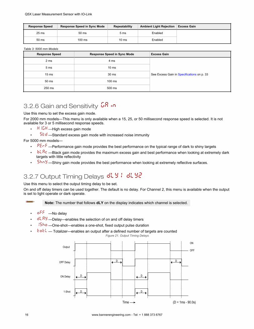
3.2.7 Output Timing Delays Use this menu to select the output timing delay to be set.On and off delay timers can be used together. The default is no delay. For Channel 2, this menu is available when the outputis set to light operate or dark operate.
Note: The number that follows dLY on the display indicates which channel is selected.
• —No delay• —Delay—enables the selection of on and off delay timers• —One-shot—enables a one-shot, fixed output pulse duration• — Totalizer—enables an output after a defined number of targets are counted
Figure 21. Output Timing Delays
Output
OFF Delay
ON Delay
Time
1-Shot
ON
OFF
D
D
D
D
D D
(D = 1ms - 90.0s)
Q5X Laser Measurement Sensor with IO-Link
16 www.bannerengineering.com - Tel: + 1 888 373 6767
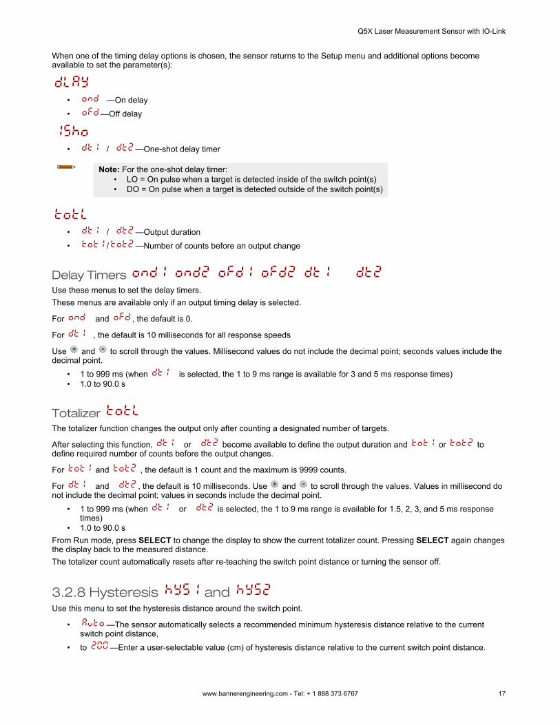
When one of the timing delay options is chosen, the sensor returns to the Setup menu and additional options becomeavailable to set the parameter(s):
• —On delay• —Off delay
• / —One-shot delay timer
Note: For the one-shot delay timer:• LO = On pulse when a target is detected inside of the switch point(s)• DO = On pulse when a target is detected outside of the switch point(s)
• / —Output duration• / —Number of counts before an output change
Delay Timers Use these menus to set the delay timers.These menus are available only if an output timing delay is selected.
For and , the default is 0.
For , the default is 10 milliseconds for all response speeds
Use and to scroll through the values. Millisecond values do not include the decimal point; seconds values include thedecimal point.
• 1 to 999 ms (when is selected, the 1 to 9 ms range is available for 3 and 5 ms response times)• 1.0 to 90.0 s
Totalizer The totalizer function changes the output only after counting a designated number of targets.
After selecting this function, or become available to define the output duration and or todefine required number of counts before the output changes.
For and , the default is 1 count and the maximum is 9999 counts.
For and , the default is 10 milliseconds. Use and to scroll through the values. Values in millisecond donot include the decimal point; values in seconds include the decimal point.
• 1 to 999 ms (when or is selected, the 1 to 9 ms range is available for 1.5, 2, 3, and 5 ms responsetimes)
• 1.0 to 90.0 sFrom Run mode, press SELECT to change the display to show the current totalizer count. Pressing SELECT again changesthe display back to the measured distance.The totalizer count automatically resets after re-teaching the switch point distance or turning the sensor off.
3.2.8 Hysteresis and Use this menu to set the hysteresis distance around the switch point.
• —The sensor automatically selects a recommended minimum hysteresis distance relative to the currentswitch point distance,
• to —Enter a user-selectable value (cm) of hysteresis distance relative to the current switch point distance.
Q5X Laser Measurement Sensor with IO-Link
www.bannerengineering.com - Tel: + 1 888 373 6767 17
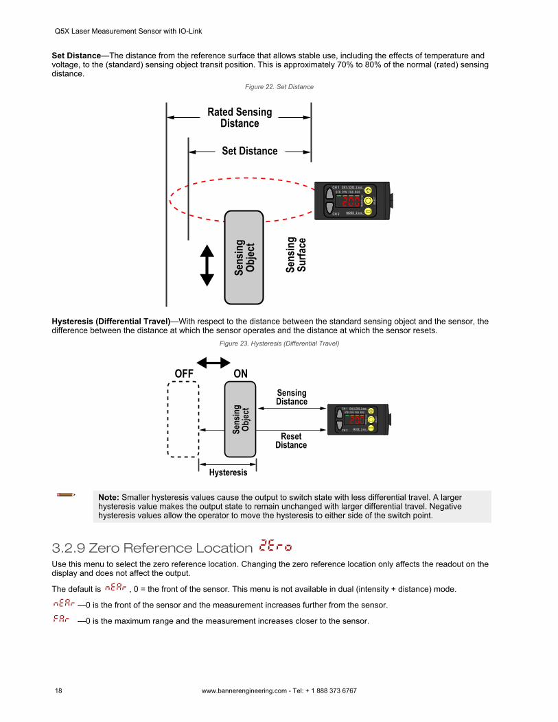
Set Distance—The distance from the reference surface that allows stable use, including the effects of temperature andvoltage, to the (standard) sensing object transit position. This is approximately 70% to 80% of the normal (rated) sensingdistance.
Figure 22. Set Distance
Rated Sensing Distance
Set Distance
Sens
ing
Surfa
ce
Sens
ing
Objec
t
Hysteresis (Differential Travel)—With respect to the distance between the standard sensing object and the sensor, thedifference between the distance at which the sensor operates and the distance at which the sensor resets.
Figure 23. Hysteresis (Differential Travel)
Sensing Distance
Reset Distance
Sens
ing
Objec
t
OFF ON
Hysteresis
Note: Smaller hysteresis values cause the output to switch state with less differential travel. A largerhysteresis value makes the output state to remain unchanged with larger differential travel. Negativehysteresis values allow the operator to move the hysteresis to either side of the switch point.
3.2.9 Zero Reference Location Use this menu to select the zero reference location. Changing the zero reference location only affects the readout on thedisplay and does not affect the output.
The default is , 0 = the front of the sensor. This menu is not available in dual (intensity + distance) mode.
—0 is the front of the sensor and the measurement increases further from the sensor.
—0 is the maximum range and the measurement increases closer to the sensor.
Q5X Laser Measurement Sensor with IO-Link
18 www.bannerengineering.com - Tel: + 1 888 373 6767
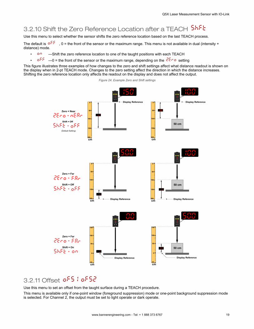
3.2.10 Shift the Zero Reference Location after a TEACH Use this menu to select whether the sensor shifts the zero reference location based on the last TEACH process.
The default is , 0 = the front of the sensor or the maximum range. This menu is not available in dual (intensity +distance) mode.
• —Shift the zero reference location to one of the taught positions with each TEACH• —0 = the front of the sensor or the maximum range, depending on the setting
This figure illustrates three examples of how changes to the zero and shift settings affect what distance readout is shown onthe display when in 2-pt TEACH mode. Changes to the zero setting affect the direction in which the distance increases.Shifting the zero reference location only affects the readout on the display and does not affect the output.
Figure 24. Example Zero and Shift settings
Zero = Near
(Default Setting)
Shift = Off
=
=
Zero = Far
Shift = Off
=
=
Zero = Far
Shift = On
=
=
Display Reference Display Reference
50 cm
Display Reference Display Reference
Display Reference Display Reference
cm200
0
100
50
150
cm200
0
100
50
150
cm200
0
100
50
150
cm200
0
100
50
150
cm-50
150
50
100
0
cm-50
150
50
100
0
50 cm
50 cm
3.2.11 Offset Use this menu to set an offset from the taught surface during a TEACH procedure.This menu is available only if one-point window (foreground suppression) mode or one-point background suppression modeis selected. For Channel 2, the output must be set to light operate or dark operate.
Q5X Laser Measurement Sensor with IO-Link
www.bannerengineering.com - Tel: + 1 888 373 6767 19
Note: The number that follows on the display indicates which channel is selected.
The offset is automatically calculated or manually defined as a consistently applied value. Auto is the default option. Use +/-to select a value. Values increase or decrease by up to 191 cm for 2000 mm models and up to 497 cm for 5000 mm models.For BGS mode, the default is Auto because the Q5X automatically selects where to position the switch point. For FGSmode, the default is 0 because the window is centered around the taught target.A positive offset value always shifts the switch point location or the FGS window towards the sensor.The taught surface must be inside of the defined sensing range. When the teach mode is set to FGS, some portion of thewindow must be located within the sensing range. When the teach mode is set to BGS, the offset value must be within thedefined sensing range. If an offset value falls outside of the sensing range, a message displays. See the applicable TEACHprocedure for more information.
3.2.12 Display View Use this menu to select the display view.When the sensor is in sleep mode, the display wakes with the first button press.
—Normal (default setting)
—Inverted (rotated 180°)
—Normal and the display enters sleep mode after 60 seconds
—Inverted (rotated 180°) and the display enters sleep mode after 60 seconds
3.2.13 Units Use this menu to set the displayed units to centimeters (cm), inches ("), millimeters (mm).
• —centimeter (with a decimal point at < 60 centimeters)• —inch (with a decimal point at < 24 inches)• — millimeter
3.2.14 Output Type Polarity Use this menu to select the output polarity.
• (Default)—Push-Pull IO-Link on pin 4 and solid state PNP on pin 2• —Solid state PNP on pins 2 and 4• —Solid state NPN on pins 2 and 4
3.2.15 Exit Setup Mode Use this menu to end Setup mode.
Navigate to and press SELECT to exit Setup mode and return to Run mode.
3.2.16 Reset to Factory Defaults Use this menu to restore the sensor to the factory default settings.
—Select to return to the sensor menu without restoring the defaults.
—Select to apply the factory defaults and return to Run mode.
Q5X Laser Measurement Sensor with IO-Link
20 www.bannerengineering.com - Tel: + 1 888 373 6767
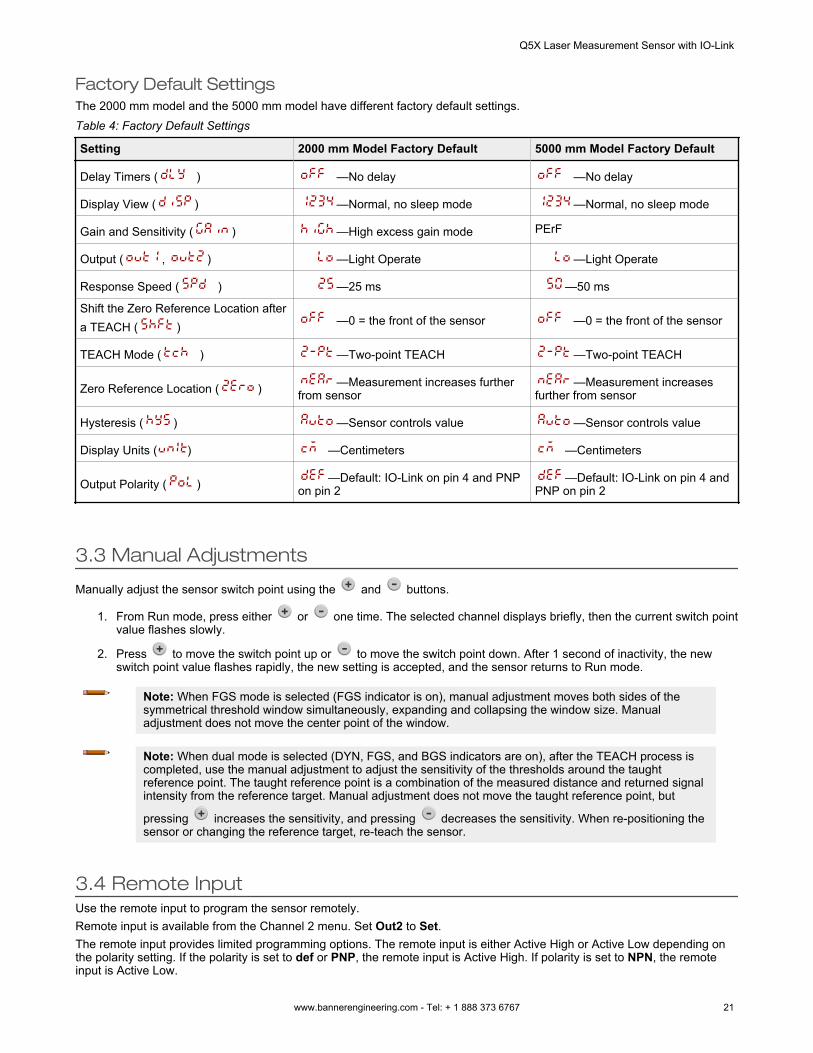
Factory Default SettingsThe 2000 mm model and the 5000 mm model have different factory default settings.Table 4: Factory Default Settings
Setting 2000 mm Model Factory Default 5000 mm Model Factory Default
Delay Timers ( ) —No delay —No delay
Display View ( ) —Normal, no sleep mode —Normal, no sleep mode
Gain and Sensitivity ( ) —High excess gain mode PErF
Output ( , ) —Light Operate —Light Operate
Response Speed ( ) —25 ms —50 ms
Shift the Zero Reference Location aftera TEACH ( ) —0 = the front of the sensor —0 = the front of the sensor
TEACH Mode ( ) —Two-point TEACH —Two-point TEACH
Zero Reference Location ( ) —Measurement increases furtherfrom sensor
—Measurement increasesfurther from sensor
Hysteresis ( ) —Sensor controls value —Sensor controls value
Display Units ( ) —Centimeters —Centimeters
Output Polarity ( ) —Default: IO-Link on pin 4 and PNPon pin 2
—Default: IO-Link on pin 4 andPNP on pin 2
3.3 Manual Adjustments
Manually adjust the sensor switch point using the and buttons.
1. From Run mode, press either or one time. The selected channel displays briefly, then the current switch pointvalue flashes slowly.
2. Press to move the switch point up or to move the switch point down. After 1 second of inactivity, the newswitch point value flashes rapidly, the new setting is accepted, and the sensor returns to Run mode.
Note: When FGS mode is selected (FGS indicator is on), manual adjustment moves both sides of thesymmetrical threshold window simultaneously, expanding and collapsing the window size. Manualadjustment does not move the center point of the window.
Note: When dual mode is selected (DYN, FGS, and BGS indicators are on), after the TEACH process iscompleted, use the manual adjustment to adjust the sensitivity of the thresholds around the taughtreference point. The taught reference point is a combination of the measured distance and returned signalintensity from the reference target. Manual adjustment does not move the taught reference point, but
pressing increases the sensitivity, and pressing decreases the sensitivity. When re-positioning thesensor or changing the reference target, re-teach the sensor.
3.4 Remote InputUse the remote input to program the sensor remotely.Remote input is available from the Channel 2 menu. Set Out2 to Set.The remote input provides limited programming options. The remote input is either Active High or Active Low depending onthe polarity setting. If the polarity is set to def or PNP, the remote input is Active High. If polarity is set to NPN, the remoteinput is Active Low.
Q5X Laser Measurement Sensor with IO-Link
www.bannerengineering.com - Tel: + 1 888 373 6767 21
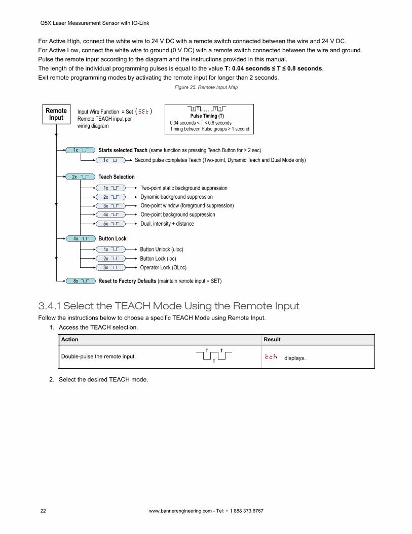
For Active High, connect the white wire to 24 V DC with a remote switch connected between the wire and 24 V DC.For Active Low, connect the white wire to ground (0 V DC) with a remote switch connected between the wire and ground.Pulse the remote input according to the diagram and the instructions provided in this manual.The length of the individual programming pulses is equal to the value T: 0.04 seconds ≤ T ≤ 0.8 seconds.Exit remote programming modes by activating the remote input for longer than 2 seconds.
Figure 25. Remote Input Map
1x
2x Teach Selection
Starts selected Teach (same function as pressing Teach Button for > 2 sec)1x Second pulse completes Teach (Two-point, Dynamic Teach and Dual Mode only)
0.04 seconds < T < 0.8 secondsTiming between Pulse groups > 1 second
Pulse Timing (T)Input Wire Function = Set Remote TEACH input perwiring diagram
2x1x Two-point static background suppression
Dynamic background suppression
4x3x One-point window (foreground suppression)
One-point background suppression5x Dual, intensity + distance
4x
2x1x Button Unlock (uloc)
3x Operator Lock (OLoc)Button Lock (loc)
Button Lock
8x Reset to Factory Defaults (maintain remote input = SET)
Remote Input
3.4.1 Select the TEACH Mode Using the Remote InputFollow the instructions below to choose a specific TEACH Mode using Remote Input.
1. Access the TEACH selection.
Action Result
Double-pulse the remote input.T T
T displays.
2. Select the desired TEACH mode.
Q5X Laser Measurement Sensor with IO-Link
22 www.bannerengineering.com - Tel: + 1 888 373 6767
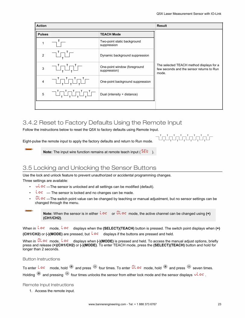
Action Result
Pulses TEACH Mode
1T Two-point static background
suppression
2T T
TDynamic background suppression
3T T
T
T
TOne-point window (foregroundsuppression)
4T T
T T T
T TOne-point background suppression
5T T
T
T
T
T
T
T
TDual (intensity + distance)
The selected TEACH method displays for afew seconds and the sensor returns to Runmode.
3.4.2 Reset to Factory Defaults Using the Remote InputFollow the instructions below to reset the Q5X to factory defaults using Remote Input.
Eight-pulse the remote input to apply the factory defaults and return to Run mode. T
T
T
T
T
T
T
T
T
T
T
T T
T
T
Note: The input wire function remains at remote teach input ( ).
3.5 Locking and Unlocking the Sensor ButtonsUse the lock and unlock feature to prevent unauthorized or accidental programming changes.Three settings are available:
• —The sensor is unlocked and all settings can be modified (default).• — The sensor is locked and no changes can be made.• —The switch point value can be changed by teaching or manual adjustment, but no sensor settings can be
changed through the menu.
Note: When the sensor is in either or mode, the active channel can be changed using (+)(CH1/CH2).
When in mode, displays when the (SELECT)(TEACH) button is pressed. The switch point displays when (+)(CH1/CH2) or (-)(MODE) are pressed, but displays if the buttons are pressed and held.
When in mode, displays when (-)(MODE) is pressed and held. To access the manual adjust options, brieflypress and release (+)(CH1/CH2) or (-)(MODE). To enter TEACH mode, press the (SELECT)(TEACH) button and hold forlonger than 2 seconds.
Button Instructions
To enter mode, hold and press four times. To enter mode, hold and press seven times.
Holding and pressing four times unlocks the sensor from either lock mode and the sensor displays .
Remote Input Instructions1. Access the remote input.
Q5X Laser Measurement Sensor with IO-Link
www.bannerengineering.com - Tel: + 1 888 373 6767 23
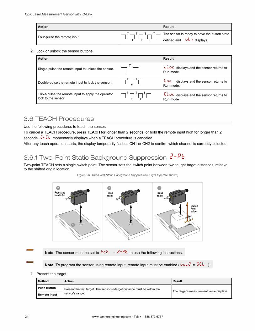
Action Result
Four-pulse the remote input.T T
T T T
T T The sensor is ready to have the button state
defined and displays.
2. Lock or unlock the sensor buttons.
Action Result
Single-pulse the remote input to unlock the sensor.T displays and the sensor returns to
Run mode.
Double-pulse the remote input to lock the sensor.T T
T displays and the sensor returns to
Run mode.
Triple-pulse the remote input to apply the operatorlock to the sensor
T T
T
T
T displays and the sensor returns to
Run mode
3.6 TEACH ProceduresUse the following procedures to teach the sensor.To cancel a TEACH procedure, press TEACH for longer than 2 seconds, or hold the remote input high for longer than 2seconds. momentarily displays when a TEACH procedure is canceled.After any teach operation starts, the display temporarily flashes CH1 or CH2 to confirm which channel is currently selected.
3.6.1 Two-Point Static Background Suppression Two-point TEACH sets a single switch point. The sensor sets the switch point between two taught target distances, relativeto the shifted origin location.
Figure 26. Two-Point Static Background Suppression (Light Operate shown)
1
Switch Point Value
4
2Press and Hold > 2s
Press again
3Press again
5
Note: The sensor must be set to = to use the following instructions.
Note: To program the sensor using remote input, remote input must be enabled ( = ).
1. Present the target.
Method Action Result
Push Button Present the first target. The sensor-to-target distance must be within thesensor's range.
The target's measurement value displays.Remote Input
Q5X Laser Measurement Sensor with IO-Link
24 www.bannerengineering.com - Tel: + 1 888 373 6767
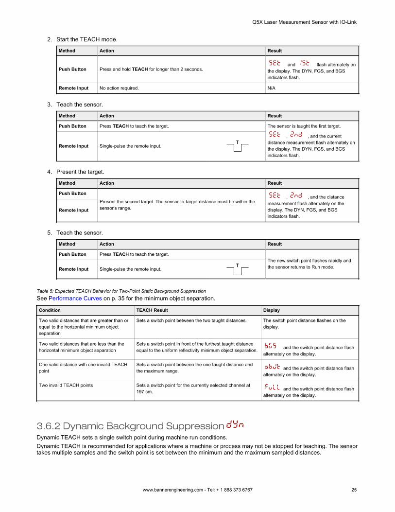
2. Start the TEACH mode.
Method Action Result
Push Button Press and hold TEACH for longer than 2 seconds. and flash alternately on
the display. The DYN, FGS, and BGSindicators flash.
Remote Input No action required. N/A
3. Teach the sensor.
Method Action Result
Push Button Press TEACH to teach the target. The sensor is taught the first target.
, , and the currentdistance measurement flash alternately onthe display. The DYN, FGS, and BGSindicators flash.
Remote Input Single-pulse the remote input.T
4. Present the target.
Method Action Result
Push ButtonPresent the second target. The sensor-to-target distance must be within thesensor's range.
, , and the distancemeasurement flash alternately on thedisplay. The DYN, FGS, and BGSindicators flash.
Remote Input
5. Teach the sensor.
Method Action Result
Push Button Press TEACH to teach the target.The new switch point flashes rapidly andthe sensor returns to Run mode.Remote Input Single-pulse the remote input.
T
Table 5: Expected TEACH Behavior for Two-Point Static Background SuppressionSee Performance Curves on p. 35 for the minimum object separation.
Condition TEACH Result Display
Two valid distances that are greater than orequal to the horizontal minimum objectseparation
Sets a switch point between the two taught distances. The switch point distance flashes on thedisplay.
Two valid distances that are less than thehorizontal minimum object separation
Sets a switch point in front of the furthest taught distanceequal to the uniform reflectivity minimum object separation. and the switch point distance flash
alternately on the display.
One valid distance with one invalid TEACHpoint
Sets a switch point between the one taught distance andthe maximum range. and the switch point distance flash
alternately on the display.
Two invalid TEACH points Sets a switch point for the currently selected channel at197 cm. and the switch point distance flash
alternately on the display.
3.6.2 Dynamic Background SuppressionDynamic TEACH sets a single switch point during machine run conditions.Dynamic TEACH is recommended for applications where a machine or process may not be stopped for teaching. The sensortakes multiple samples and the switch point is set between the minimum and the maximum sampled distances.
Q5X Laser Measurement Sensor with IO-Link
www.bannerengineering.com - Tel: + 1 888 373 6767 25
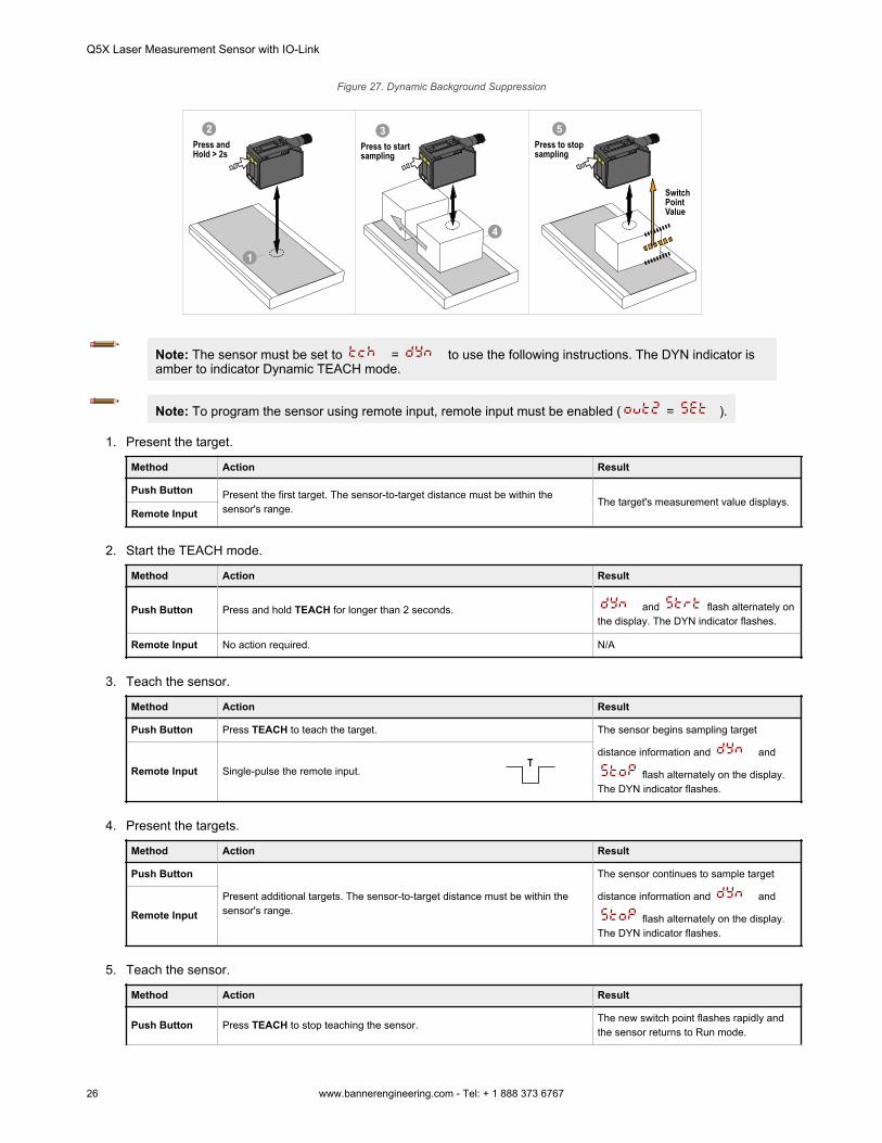
Figure 27. Dynamic Background Suppression
Switch Point Value
1
4
Press to start sampling
Press to stop sampling
2Press and Hold > 2s
3 5
Note: The sensor must be set to = to use the following instructions. The DYN indicator isamber to indicator Dynamic TEACH mode.
Note: To program the sensor using remote input, remote input must be enabled ( = ).
1. Present the target.
Method Action Result
Push Button Present the first target. The sensor-to-target distance must be within thesensor's range.
The target's measurement value displays.Remote Input
2. Start the TEACH mode.
Method Action Result
Push Button Press and hold TEACH for longer than 2 seconds. and flash alternately onthe display. The DYN indicator flashes.
Remote Input No action required. N/A
3. Teach the sensor.
Method Action Result
Push Button Press TEACH to teach the target. The sensor begins sampling target
distance information and and
flash alternately on the display.The DYN indicator flashes.
Remote Input Single-pulse the remote input.T
4. Present the targets.
Method Action Result
Push Button
Present additional targets. The sensor-to-target distance must be within thesensor's range.
The sensor continues to sample target
distance information and and
flash alternately on the display.The DYN indicator flashes.
Remote Input
5. Teach the sensor.
Method Action Result
Push Button Press TEACH to stop teaching the sensor.The new switch point flashes rapidly andthe sensor returns to Run mode.
Q5X Laser Measurement Sensor with IO-Link
26 www.bannerengineering.com - Tel: + 1 888 373 6767
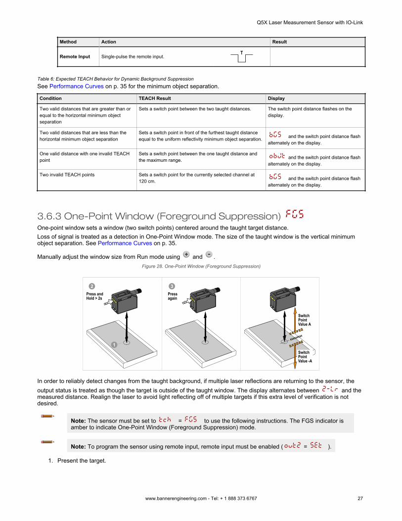
Method Action Result
Remote Input Single-pulse the remote input.T
Table 6: Expected TEACH Behavior for Dynamic Background SuppressionSee Performance Curves on p. 35 for the minimum object separation.
Condition TEACH Result Display
Two valid distances that are greater than orequal to the horizontal minimum objectseparation
Sets a switch point between the two taught distances. The switch point distance flashes on thedisplay.
Two valid distances that are less than thehorizontal minimum object separation
Sets a switch point in front of the furthest taught distanceequal to the uniform reflectivity minimum object separation. and the switch point distance flash
alternately on the display.
One valid distance with one invalid TEACHpoint
Sets a switch point between the one taught distance andthe maximum range. and the switch point distance flash
alternately on the display.
Two invalid TEACH points Sets a switch point for the currently selected channel at120 cm. and the switch point distance flash
alternately on the display.
3.6.3 One-Point Window (Foreground Suppression) One-point window sets a window (two switch points) centered around the taught target distance.Loss of signal is treated as a detection in One-Point Window mode. The size of the taught window is the vertical minimumobject separation. See Performance Curves on p. 35.
Manually adjust the window size from Run mode using and .Figure 28. One-Point Window (Foreground Suppression)
Switch Point Value A
Switch Point Value -A
1
2Press and Hold > 2s
Press again
3
In order to reliably detect changes from the taught background, if multiple laser reflections are returning to the sensor, theoutput status is treated as though the target is outside of the taught window. The display alternates between and themeasured distance. Realign the laser to avoid light reflecting off of multiple targets if this extra level of verification is notdesired.
Note: The sensor must be set to = to use the following instructions. The FGS indicator isamber to indicate One-Point Window (Foreground Suppression) mode.
Note: To program the sensor using remote input, remote input must be enabled ( = ).
1. Present the target.
Q5X Laser Measurement Sensor with IO-Link
www.bannerengineering.com - Tel: + 1 888 373 6767 27
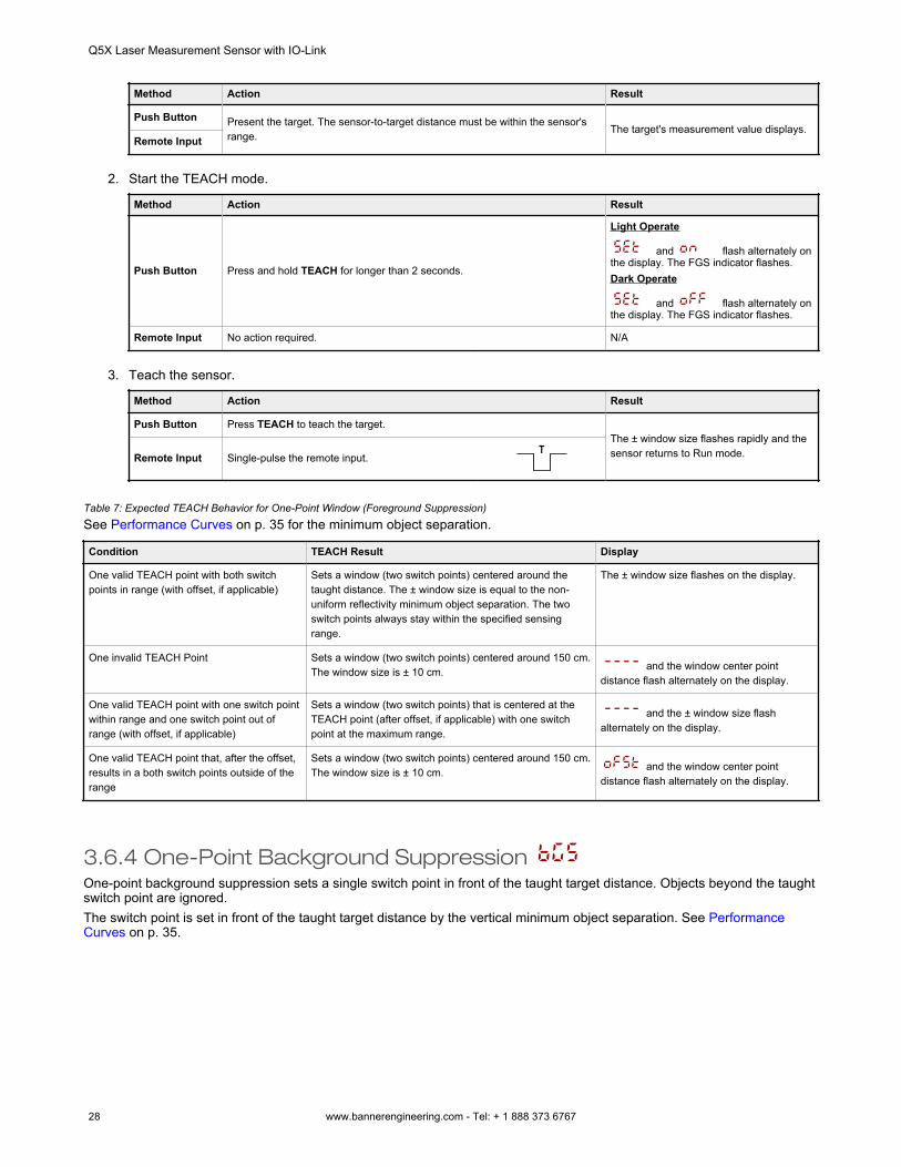
Method Action Result
Push Button Present the target. The sensor-to-target distance must be within the sensor'srange.
The target's measurement value displays.Remote Input
2. Start the TEACH mode.
Method Action Result
Push Button Press and hold TEACH for longer than 2 seconds.
Light Operate
and flash alternately onthe display. The FGS indicator flashes.Dark Operate
and flash alternately onthe display. The FGS indicator flashes.
Remote Input No action required. N/A
3. Teach the sensor.
Method Action Result
Push Button Press TEACH to teach the target.The ± window size flashes rapidly and thesensor returns to Run mode.Remote Input Single-pulse the remote input.
T
Table 7: Expected TEACH Behavior for One-Point Window (Foreground Suppression)See Performance Curves on p. 35 for the minimum object separation.
Condition TEACH Result Display
One valid TEACH point with both switchpoints in range (with offset, if applicable)
Sets a window (two switch points) centered around thetaught distance. The ± window size is equal to the non-uniform reflectivity minimum object separation. The twoswitch points always stay within the specified sensingrange.
The ± window size flashes on the display.
One invalid TEACH Point Sets a window (two switch points) centered around 150 cm.The window size is ± 10 cm. and the window center point
distance flash alternately on the display.
One valid TEACH point with one switch pointwithin range and one switch point out ofrange (with offset, if applicable)
Sets a window (two switch points) that is centered at theTEACH point (after offset, if applicable) with one switchpoint at the maximum range.
and the ± window size flashalternately on the display.
One valid TEACH point that, after the offset,results in a both switch points outside of therange
Sets a window (two switch points) centered around 150 cm.The window size is ± 10 cm. and the window center point
distance flash alternately on the display.
3.6.4 One-Point Background Suppression One-point background suppression sets a single switch point in front of the taught target distance. Objects beyond the taughtswitch point are ignored.The switch point is set in front of the taught target distance by the vertical minimum object separation. See PerformanceCurves on p. 35.
Q5X Laser Measurement Sensor with IO-Link
28 www.bannerengineering.com - Tel: + 1 888 373 6767
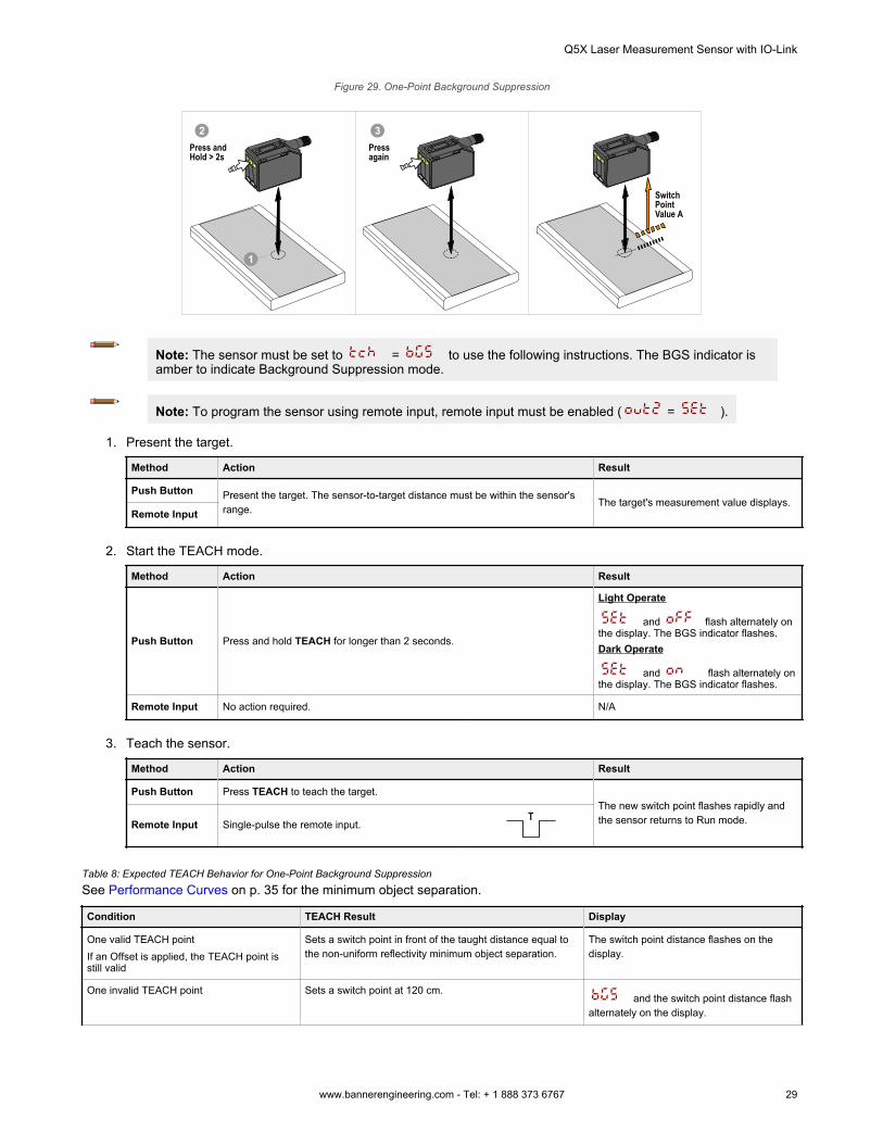
Figure 29. One-Point Background Suppression
Switch Point Value A
1
2Press and Hold > 2s
Press again
3
Note: The sensor must be set to = to use the following instructions. The BGS indicator isamber to indicate Background Suppression mode.
Note: To program the sensor using remote input, remote input must be enabled ( = ).
1. Present the target.
Method Action Result
Push Button Present the target. The sensor-to-target distance must be within the sensor'srange.
The target's measurement value displays.Remote Input
2. Start the TEACH mode.
Method Action Result
Push Button Press and hold TEACH for longer than 2 seconds.
Light Operate
and flash alternately onthe display. The BGS indicator flashes.Dark Operate
and flash alternately onthe display. The BGS indicator flashes.
Remote Input No action required. N/A
3. Teach the sensor.
Method Action Result
Push Button Press TEACH to teach the target.The new switch point flashes rapidly andthe sensor returns to Run mode.Remote Input Single-pulse the remote input.
T
Table 8: Expected TEACH Behavior for One-Point Background SuppressionSee Performance Curves on p. 35 for the minimum object separation.
Condition TEACH Result Display
One valid TEACH pointIf an Offset is applied, the TEACH point isstill valid
Sets a switch point in front of the taught distance equal tothe non-uniform reflectivity minimum object separation.
The switch point distance flashes on thedisplay.
One invalid TEACH point Sets a switch point at 120 cm. and the switch point distance flash
alternately on the display.
Q5X Laser Measurement Sensor with IO-Link
www.bannerengineering.com - Tel: + 1 888 373 6767 29
Condition TEACH Result Display
One valid TEACH point that, after offset,becomes invalid
Sets a switch point at 120 cm. and the switch point distance flash
alternately on the display.
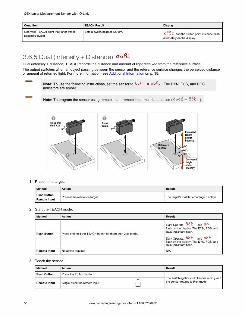
3.6.5 Dual (Intensity + Distance) Dual (intensity + distance) TEACH records the distance and amount of light received from the reference surface.The output switches when an object passing between the sensor and the reference surface changes the perceived distanceor amount of returned light. For more information, see Additional Information on p. 38.
Note: To use the following instructions, set the sensor to = . The DYN, FGS, and BGSindicators are amber.
Note: To program the sensor using remote input, remote input must be enabled ( = ).
1
IncreasedHeightand/orIntensity
DecreasedHeightand/orIntensity
ReferenceSurface
2Press and Hold > 2s
Press again
3
1. Present the target.
Method Action Result
Push ButtonRemote Input
Present the reference target. The target's match percentage displays
2. Start the TEACH mode.
Method Action Result
Push Button Press and hold the TEACH button for more than 2 seconds.
Light Operate: and flash on the display. The DYN, FGS, andBGS indicators flash.
Dark Operate: and flash on the display. The DYN, FGS, andBGS indicators flash.
Remote Input No action required. N/A
3. Teach the sensor.
Method Action Result
Push Button Press the TEACH button.The switching threshold flashes rapidly andthe sensor returns to Run mode.Remote Input Single-pulse the remote input.
T
Q5X Laser Measurement Sensor with IO-Link
30 www.bannerengineering.com - Tel: + 1 888 373 6767
Table 9: Expected TEACH Behavior for Dual (Intensity + Distance) Mode
Condition TEACH Result Display
One valid reference surface is taught withinsensing range
Sets a dual (intensity + distance) windowcentered around the taught reference surface.The ± window size is the previously usedswitching threshold, or 50% by default.
The switching threshold flashes on the display.
One reference surface is taught outside thesensing range
Sets a dual (intensity + distance) windowcentered around the taught reference surface thatis outside the sensing range. The sensingconditions may not be as reliable.
flashes on the display.
One invalid TEACH Point No reference surface is taught, the output willchange when any object is detected. flashes on the display.
3.7 Pulse Frequency Modulation (PFM) Output The Q5X can generate pulses whose frequency are proportional to the sensor's measured distance, thereby providing amethod for representing an analog signal with only a discrete counter.The sensing range of the sensor is scaled from 100 to 600 Hz (100 Hz equals the near range limit of the sensor, 600 Hzequals the far sensing range limit). An output of 50 Hz represents a Loss of Signal ( ) condition where there is notarget or the target is out of the sensor's range. To find the Pulse Frequency Modulation (PFM) Output, set to .
3.8 Sync Master/SlaveTwo Q5X sensors may be used together in a single sensing application.To eliminate crosstalk between the two sensors, configure one sensor to be the master and one to be the slave. In this mode,the sensors alternate taking measurements and the response speed doubles.
Important: The master sensor and the slave sensor must be programmed for the same Response Speedand Gain and Sensitivity settings. The master sensor and slave sensor must share a common powersource.
1. Configure the first sensor as the master; navigate: > .
2. Configure the second sensor as the slave; navigate: > .3. Connect the white wires of the two sensors together.
Q5X Laser Measurement Sensor with IO-Link
www.bannerengineering.com - Tel: + 1 888 373 6767 31
4 IO-Link InterfaceIO-Link is a point-to-point communication link between a master device and sensor. Use IO-Link to parameterize sensors andtransmit process data automatically.For the latest IO-Link protocol and specifications, see www.io-link.com.Each IO-Link device has an IODD (IO Device Description) file that contains information about the manufacturer, articlenumber, functionality etc. This information can be easily read and processed by the user. Each device can be unambiguouslyidentified via the IODD as well as via an internal device ID. Download the Q5X's IO-Link IODD package (p/n 206833 for the2000 mm models; 217156 for the 5000 mm models) from Banner Engineering's website at www.bannerengineering.com.Banner has also developed Add On Instruction (AOI) files to simplify ease-of-use between the Q5X, multiple third-partyvendors' IO-Link masters, and the Logix Designer software package for Rockwell Automation PLCs. Three types of AOI filesfor Rockwell Allen-Bradley PLCs are listed below. These files and more information can be found at www.bannerengineering.com.Process Data AOIs—These files can be used alone, without the need for any other IO-Link AOIs. The job of a Process DataAOI is to intelligently parse out the Process Data word(s) in separate pieces of information. All that is required to make use ofthis AOI is an EtherNet/IP connection to the IO-Link Master and knowledge of where the Process Data registers are locatedfor each port.Parameter Data AOIs—These files require the use of an associated IO-Link Master AOI. The job of a Parameter Data AOI,when working in conjunction with the IO-Link Master AOI, is to provide quasi-realtime read/write access to all IO-Linkparameter data in the sensor. Each Parameter Data AOI is specific to a given sensor or device.IO-Link Master AOIs—These files require the use of one or more associated Parameter Data AOIs. The job of an IO-LinkMaster AOI is to translate the desired IO-Link read/write requests, made by the Parameter Data AOI, into the format aspecific IO-Link Master requires. Each IO-Link Master AOI is customized for a given brand of IO-Link Master.Add and configure the relevant Banner IO-Link Master AOI in your ladder logic program first; then add and configure BannerIO-Link Device AOIs as desired, linking them to the Master AOI as shown in the relevant AOI documentation.
Q5X Laser Measurement Sensor with IO-Link
32 www.bannerengineering.com - Tel: + 1 888 373 6767
5 Specifications
5.1 SpecificationsSensing Beam
Visible red Class 2 laser models, 650 nmSupply Voltage (Vcc)
10 to 30 V DC (Class 2 supply) (10% max ripple within limits)Supply Protection Circuitry
Protected against reverse polarity and transient overvoltagesPower and Current Consumption, exclusive of load
2000 mm model: < 1 W5000 mm model: < 1.4 W
Sensing Range2000 mm model: 95 mm to 2000 mm (3.74 in to 78.74 in)5000 mm model: 50 mm to 5000 mm (2 in to 16.4 ft)
Output ConfigurationChannel 1: IO-Link, Push/pull output, configurable PNP or NPN outputChannel 2: Multi-function remote input/output, configurable PNP or NPN,or pulse frequency modulated output
Output RatingCurrent rating: 50 mA maximum
Black wire specifications per configuration
IO-Link Push/PullOutput High: ≥ Vsupply - 2.5 V
Output Low: ≤ 2.5 V
PNPOutput High: ≥ Vsupply - 2.5 V
Output Low: ≤ 1V (loads ≤ 1 MegΩ)
NPNOutput High: ≥ Vsupply - 2.5 V (loads ≤ 50 kΩ)
Output Low: ≤ 2.5 V
White wire specifications per configuration
PNPOutput High: ≥ Vsupply - 2.5 V
Output Low: ≤ 2.5 V (loads ≤ 70 kΩ)
NPNOutput High: ≥ Vsupply - 2.5 V (loads ≤ 70 kΩ)
Output Low: ≤ 2.5 V
Boresighting2000 mm model: ± 43 mm at 2000 mm5000 mm model: ± 86 mm at 5000 mm
Response Speed2000 mm model: User selectable 3, 5, 15, 25, or 50 ms5000 mm model: User selectable 2, 5, 15, 50, or 250 ms
Delay at Power Up< 2.5 s
Maximum TorqueSide mounting: 1 N·m (9 in·lbs)
Ambient Light Immunity2000 mm model:
5000 lux at 1 m2000 lux at 2 m
5000 mm model: 5000 luxConnector
Integral 4-pin M12 male quick disconnectConstruction
Housing: ABSLens cover: PMMA acrylicLightpipe and display window: polycarbonate
Temperature Effect (Typical) for 2000 mm Models< 0.5 mm/°C at < 500 mm< 1.0 mm/°C at < 1000 mm< 2.0 mm/°C at < 2000 mm
Temperature Effect (Typical) for 5000 mm Models< 0.5mm/°C for up to 3000 mm< 0.75mm/°C for up to 5000 mm
Discrete Output Distance Repeatability
Distance (mm) Repeatability (2000 mm Models)
95 to 300 ± 0.5 mm
300 to 1000 ± 0.25%
1000 to 2000 ± 0.5%
See the charts for the Repeatability of the 5000 mm models.
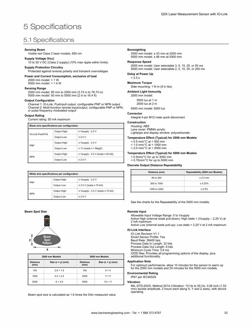
Beam Spot Size
x
yBeamSpot
Pattern
2000 mm Models 5000 mm Models
Distance(mm)
Size (x × y) (mm) Distance(mm)
Size (x × y) (mm)
100 2.6 × 1.5 100 6 × 4
1000 4.2 × 2.5 2500 11 ×7
2000 6 × 3.6 5000 15 × 11
Beam spot size is calculated as 1.6 times the D4σ measured value
Remote InputAllowable Input Voltage Range: 0 to VsupplyActive High (internal weak pull-down): High state > (Vsupply – 2.25 V) at2 mA maximumActive Low (internal weak pull-up): Low state < 2.25 V at 2 mA maximum
IO-Link InterfaceIO Link Revision V1.1Smart Sensor Profile: YesBaud Rate: 38400 bpsProcess Data In Length: 32 bitsProcess Data Out Length: 8 bitsMinimum Cycle Time: 3.6 msIODD files: Provides all programming options of the display, plusadditional functionality.
Application NoteFor optimum performance, allow 10 minutes for the sensor to warm upfor the 2000 mm models and 20 minutes for the 5000 mm models.
Environmental RatingIP67 per IEC60529
VibrationMIL-STD-202G, Method 201A (Vibration: 10 Hz to 55 Hz, 0.06 inch (1.52mm) double amplitude, 2 hours each along X, Y and Z axes), with deviceoperating
Q5X Laser Measurement Sensor with IO-Link
www.bannerengineering.com - Tel: + 1 888 373 6767 33
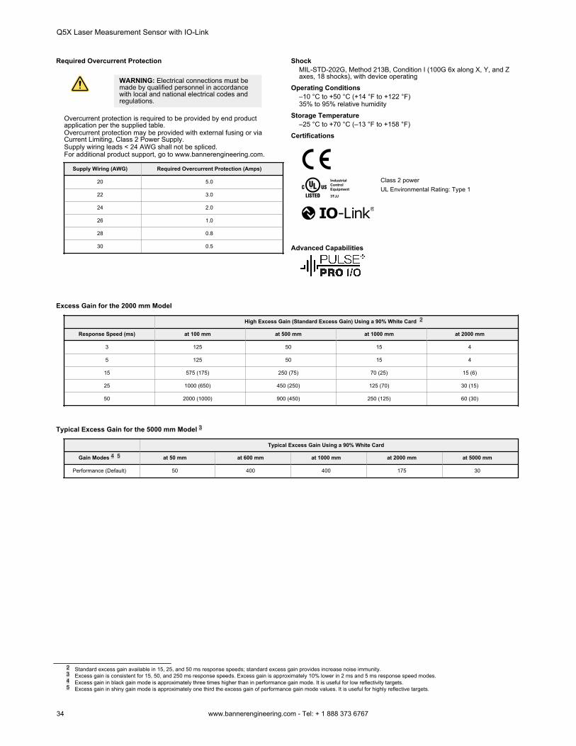
Required Overcurrent Protection
WARNING: Electrical connections must bemade by qualified personnel in accordancewith local and national electrical codes andregulations.
Overcurrent protection is required to be provided by end productapplication per the supplied table.Overcurrent protection may be provided with external fusing or viaCurrent Limiting, Class 2 Power Supply.Supply wiring leads < 24 AWG shall not be spliced.For additional product support, go to www.bannerengineering.com.
Supply Wiring (AWG) Required Overcurrent Protection (Amps)
20 5.0
22 3.0
24 2.0
26 1.0
28 0.8
30 0.5
ShockMIL-STD-202G, Method 213B, Condition I (100G 6x along X, Y, and Zaxes, 18 shocks), with device operating
Operating Conditions–10 °C to +50 °C (+14 °F to +122 °F)35% to 95% relative humidity
Storage Temperature–25 °C to +70 °C (–13 °F to +158 °F)
Certifications
IndustrialControlEquipment
3TJJ
Class 2 powerUL Environmental Rating: Type 1
Advanced Capabilities
Excess Gain for the 2000 mm Model
High Excess Gain (Standard Excess Gain) Using a 90% White Card 2
Response Speed (ms) at 100 mm at 500 mm at 1000 mm at 2000 mm
3 125 50 15 4
5 125 50 15 4
15 575 (175) 250 (75) 70 (25) 15 (6)
25 1000 (650) 450 (250) 125 (70) 30 (15)
50 2000 (1000) 900 (450) 250 (125) 60 (30)
Typical Excess Gain for the 5000 mm Model 3
Typical Excess Gain Using a 90% White Card
Gain Modes 4 5 at 50 mm at 600 mm at 1000 mm at 2000 mm at 5000 mm
Performance (Default) 50 400 400 175 30
2 Standard excess gain available in 15, 25, and 50 ms response speeds; standard excess gain provides increase noise immunity.3 Excess gain is consistent for 15, 50, and 250 ms response speeds. Excess gain is approximately 10% lower in 2 ms and 5 ms response speed modes.4 Excess gain in black gain mode is approximately three times higher than in performance gain mode. It is useful for low reflectivity targets.5 Excess gain in shiny gain mode is approximately one third the excess gain of performance gain mode values. It is useful for highly reflective targets.
Q5X Laser Measurement Sensor with IO-Link
34 www.bannerengineering.com - Tel: + 1 888 373 6767
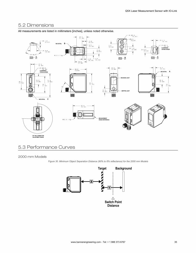
5.2 DimensionsAll measurements are listed in millimeters [inches], unless noted otherwise.
DETAIL CSCALE 2:1
SEE DETAIL B
DETAIL B DETAIL A
SEE DETAIL A
SEE DETAIL C
SCALE 2:1 SCALE 2:1
CLEARANCE FOR M4 SCREW
CLEARANCE FOR M4 SCREW
MEASUREMENT RANGE REFERENCE
270° M12 CONNECTOR ADJUSTMENT RANGE
RECEIVED LIGHT
EMITTED LIGHT
5.3 Performance Curves
2000 mm ModelsFigure 30. Minimum Object Separation Distance (90% to 6% reflectance) for the 2000 mm Models
Target
Switch Point Distance
Background
X
Y
Q5X Laser Measurement Sensor with IO-Link
www.bannerengineering.com - Tel: + 1 888 373 6767 35
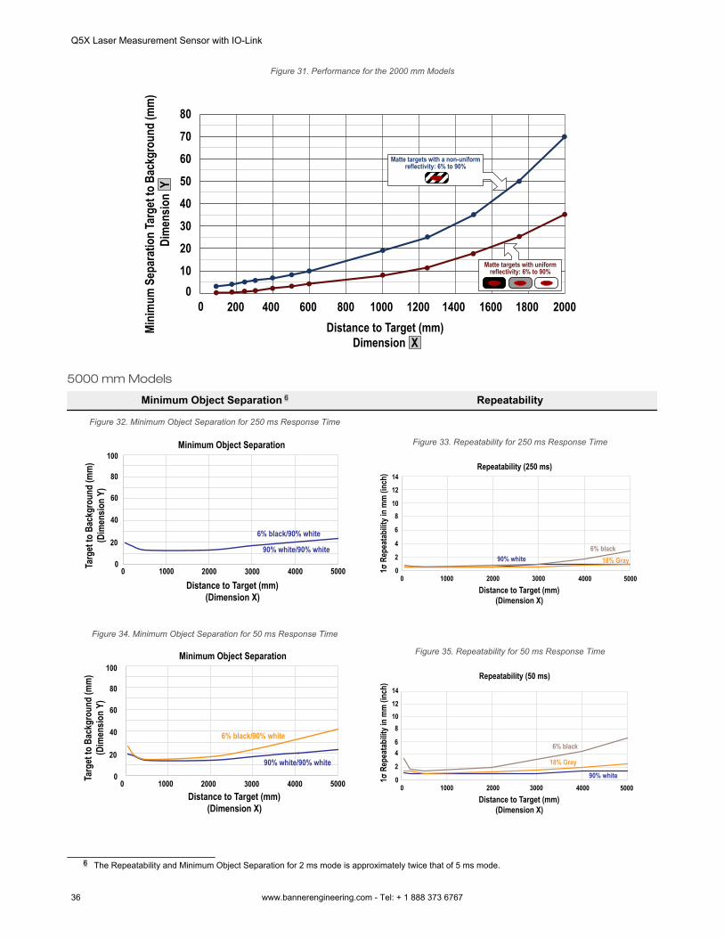
Figure 31. Performance for the 2000 mm Models
Mini
mum
Sep
arat
ion
Targ
et to
Bac
kgro
und
(mm
)Di
men
sion
Y
Distance to Target (mm)Dimension X
010
20
30
40
50
60
70
80
0 200 400 600 800 1000 1200 1400 1600 1800 2000
Matte targets with uniform reflectivity: 6% to 90%
Matte targets with a non-uniform reflectivity: 6% to 90%
5000 mm Models
Minimum Object Separation 6 Repeatability
Figure 32. Minimum Object Separation for 250 ms Response Time
Targ
et to
Bac
kgro
und
(mm
)(D
imen
sion
Y)
00
Distance to Target (mm)(Dimension X)
Minimum Object Separation
1000 2000 3000 4000 5000
6% black/90% white
90% white/90% white20
40
60
80
100Figure 33. Repeatability for 250 ms Response Time
Repeatability (250 ms)
0 1000 2000 3000 4000 50000
6% black18% Gray90% white
Distance to Target (mm)(Dimension X)
2
4
6
810
12
14
1σ R
epea
tabi
lity i
n m
m (i
nch)
Figure 34. Minimum Object Separation for 50 ms Response Time
Targ
et to
Bac
kgro
und
(mm
)(D
imen
sion
Y)
00
Distance to Target (mm)(Dimension X)
Minimum Object Separation
1000 2000 3000 4000 5000
20
40
60
80
100
6% black/90% white
90% white/90% white
Figure 35. Repeatability for 50 ms Response Time
Repeatability (50 ms)
0 1000 2000 3000 4000 50000
Distance to Target (mm)(Dimension X)
2
46
81012
14
1σ R
epea
tabi
lity i
n m
m (i
nch)
6% black
18% Gray
90% white
6 The Repeatability and Minimum Object Separation for 2 ms mode is approximately twice that of 5 ms mode.
Q5X Laser Measurement Sensor with IO-Link
36 www.bannerengineering.com - Tel: + 1 888 373 6767
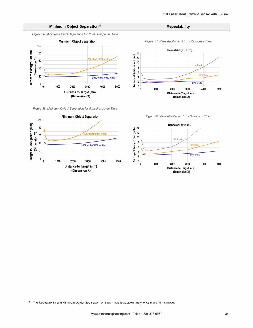
Minimum Object Separation 6 Repeatability
Figure 36. Minimum Object Separation for 15 ms Response TimeTa
rget
to B
ackg
roun
d (m
m)
(Dim
ensio
n Y)
00
Distance to Target (mm)(Dimension X)
Minimum Object Separation
1000 2000 3000 4000 5000
20
40
60
80
100
6% black/90% white
90% white/90% white
Figure 37. Repeatability for 15 ms Response Time
Repeatability (15 ms)
0 1000 2000 3000 4000 50000
Distance to Target (mm)(Dimension X)
2
4
6
8
1012
14
1σ R
epea
tabi
lity i
n m
m (i
nch)
6% black
18% Gray
90% white
Figure 38. Minimum Object Separation for 5 ms Response Time
Targ
et to
Bac
kgro
und
(mm
)(D
imen
sion
Y)
00
Distance to Target (mm)(Dimension X)
Minimum Object Separation
1000 2000 3000 4000 5000
20
40
60
80
100
6% black/90% white
90% white/90% white
Figure 39. Repeatability for 5 ms Response Time
Repeatability (5 ms)
0 1000 2000 3000 4000 50000
Distance to Target (mm)(Dimension X)
2
4
6
8
1012
14
1σ R
epea
tabi
lity i
n m
m (i
nch)
6% black
18% Gray
90% white
6 The Repeatability and Minimum Object Separation for 2 ms mode is approximately twice that of 5 ms mode.
Q5X Laser Measurement Sensor with IO-Link
www.bannerengineering.com - Tel: + 1 888 373 6767 37
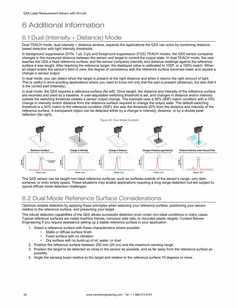
6 Additional Information
6.1 Dual (Intensity + Distance) ModeDual TEACH mode, dual intensity + distance window, expands the applications the Q5X can solve by combining distance-based detection with light intensity thresholds.In background suppression (DYN, 1-pt, 2-pt) and foreground suppression (FGS) TEACH modes, the Q5X sensor compareschanges in the measured distance between the sensor and target to control the output state. In dual TEACH mode, the userteaches the Q5X a fixed reference surface, and the sensor compares intensity and distance readings against the referencesurface it was taught. After teaching the reference target, the displayed value is calibrated to 100P, or a 100% match. Whenan object enters the sensor’s field of view, the degree of consistency with the reference surface becomes lower and causes achange in sensor output.In dual mode, you can detect when the target is present at the right distance and when it returns the right amount of light.This is useful in error-proofing applications where you need to know not only that the part is present (distance), but also that itis the correct part (intensity).In dual mode, the Q5X requires a reference surface (far left). Once taught, the distance and intensity of the reference surfaceare recorded and used as a baseline. A user-adjustable switching threshold is set, and changes in distance and/or intensityoutside the switching threshold creates a sensor output change. The example uses a 90% (90P) match condition with a 10%change in intensity and/or distance from the reference surface required to change the output state. The default-switchingthreshold is a 50% match to the reference condition (50P); this sets the threshold 50% from the distance and intensity of thereference surface. A transparent object can be detected either by a change in intensity, distance, or by a double peakreflection (far right).
Figure 40. Dual Mode Example
Reference Condition
0102030405060708090
100110120
0 25 50 75 100 125 150 175 200 225 250 275 300
10% SwitchingThreshold
100% matched distance + Intensity after Dual teach
Inten
sity
(% o
f tau
ght r
efer
ence
)
Distance (mm)
Change in Intensity
0102030405060708090
100110120
0 25 50 75 100 125 150 175 200 225 250 275 300
Output switches with intensity change
Inten
sity
(% o
f tau
ght r
efer
ence
)
Distance (mm)
Change in Distance
0102030405060708090
100110120
0 25 50 75 100 125 150 175 200 225 250 275 300
Output switches with distance change
Inten
sity
(% o
f tau
ght r
efer
ence
)
Distance (mm)
Change in Distance and Intensity
0102030405060708090
100110120
0 25 50 75 100 125 150 175 200 225 250 275 300
Output switches with intensity and distance change
Inten
sity
(% o
f tau
ght r
efer
ence
)
Distance (mm)
Reduced Intensity and/or Second Peak
0102030405060708090
100110120
0 25 50 75 100 125 150 175 200 225 250 275 300
Output switches with intensity and/or second peak (Clear Object Detection)
Inten
sity
(% o
f tau
ght r
efer
ence
)
Distance (mm)
The Q5X sensor can be taught non-ideal reference surfaces, such as surfaces outside of the sensor’s range, very darksurfaces, or even empty space. These situations may enable applications requiring a long range detection but are subject totypical diffuse mode detection challenges.
6.2 Dual Mode Reference Surface ConsiderationsOptimize reliable detection by applying these principles when selecting your reference surface, positioning your sensorrelative to the reference surface, and presenting your target.The robust detection capabilities of the Q5X allows successful detection even under non-ideal conditions in many cases.Typical reference surfaces are metal machine frames, conveyor side rails, or mounted plastic targets. Contact BannerEngineering if you require assistance setting up a stable reference surface in your application.
1. Select a reference surface with these characteristics where possible:• Matte or diffuse surface finish• Fixed surface with no vibration• Dry surface with no build-up of oil, water, or dust
2. Position the reference surface between 200 mm (20 cm) and the maximum sensing range.3. Position the target to be detected as close to the sensor as possible, and as far away from the reference surface as
possible.4. Angle the sensing beam relative to the target and relative to the reference surface 10 degrees or more.
Q5X Laser Measurement Sensor with IO-Link
38 www.bannerengineering.com - Tel: + 1 888 373 6767
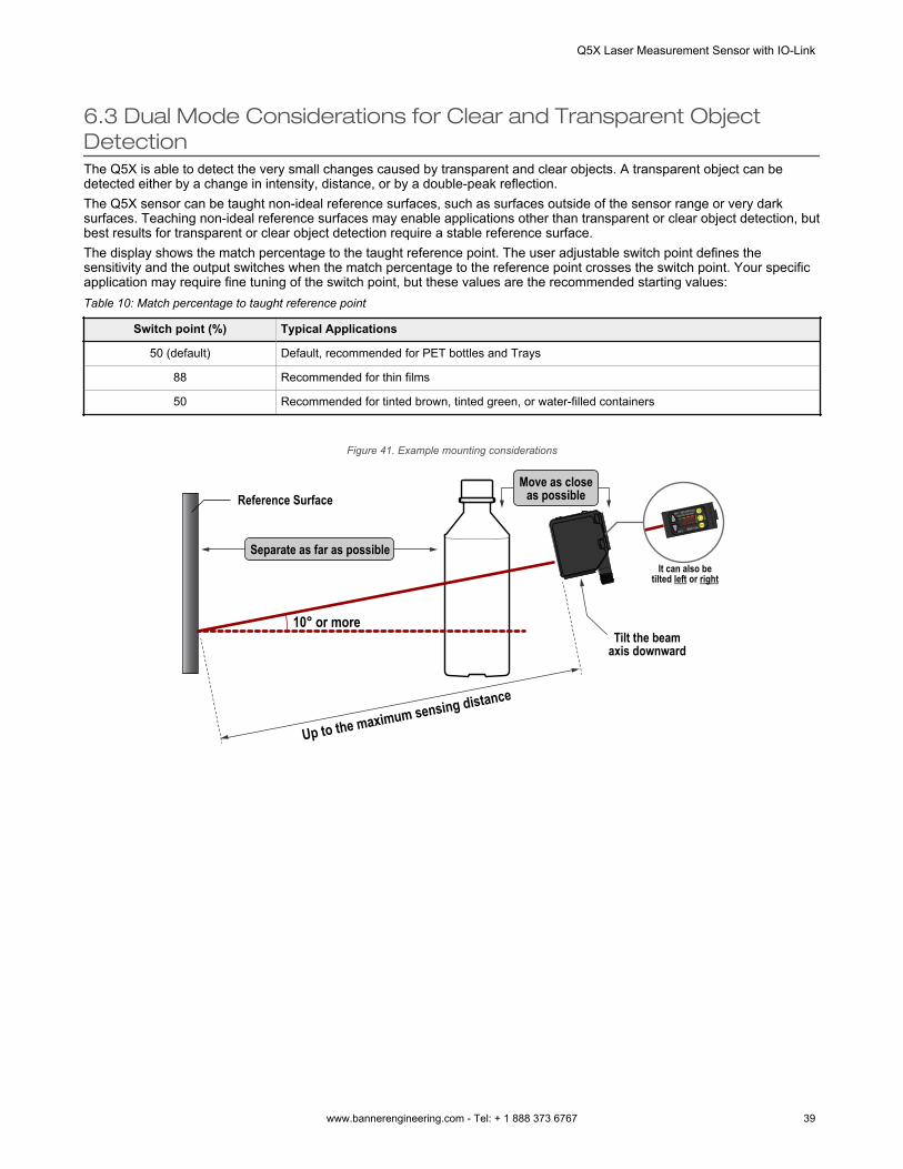
6.3 Dual Mode Considerations for Clear and Transparent ObjectDetectionThe Q5X is able to detect the very small changes caused by transparent and clear objects. A transparent object can bedetected either by a change in intensity, distance, or by a double-peak reflection.The Q5X sensor can be taught non-ideal reference surfaces, such as surfaces outside of the sensor range or very darksurfaces. Teaching non-ideal reference surfaces may enable applications other than transparent or clear object detection, butbest results for transparent or clear object detection require a stable reference surface.The display shows the match percentage to the taught reference point. The user adjustable switch point defines thesensitivity and the output switches when the match percentage to the reference point crosses the switch point. Your specificapplication may require fine tuning of the switch point, but these values are the recommended starting values:Table 10: Match percentage to taught reference point
Switch point (%) Typical Applications
50 (default) Default, recommended for PET bottles and Trays
88 Recommended for thin films
50 Recommended for tinted brown, tinted green, or water-filled containers
Figure 41. Example mounting considerations
CC
10° or more
Up to the maximum sensing distance
Reference Surface
Separate as far as possible
Move as closeas possible
Tilt the beamaxis downward
It can also betilted left or right
Q5X Laser Measurement Sensor with IO-Link
www.bannerengineering.com - Tel: + 1 888 373 6767 39
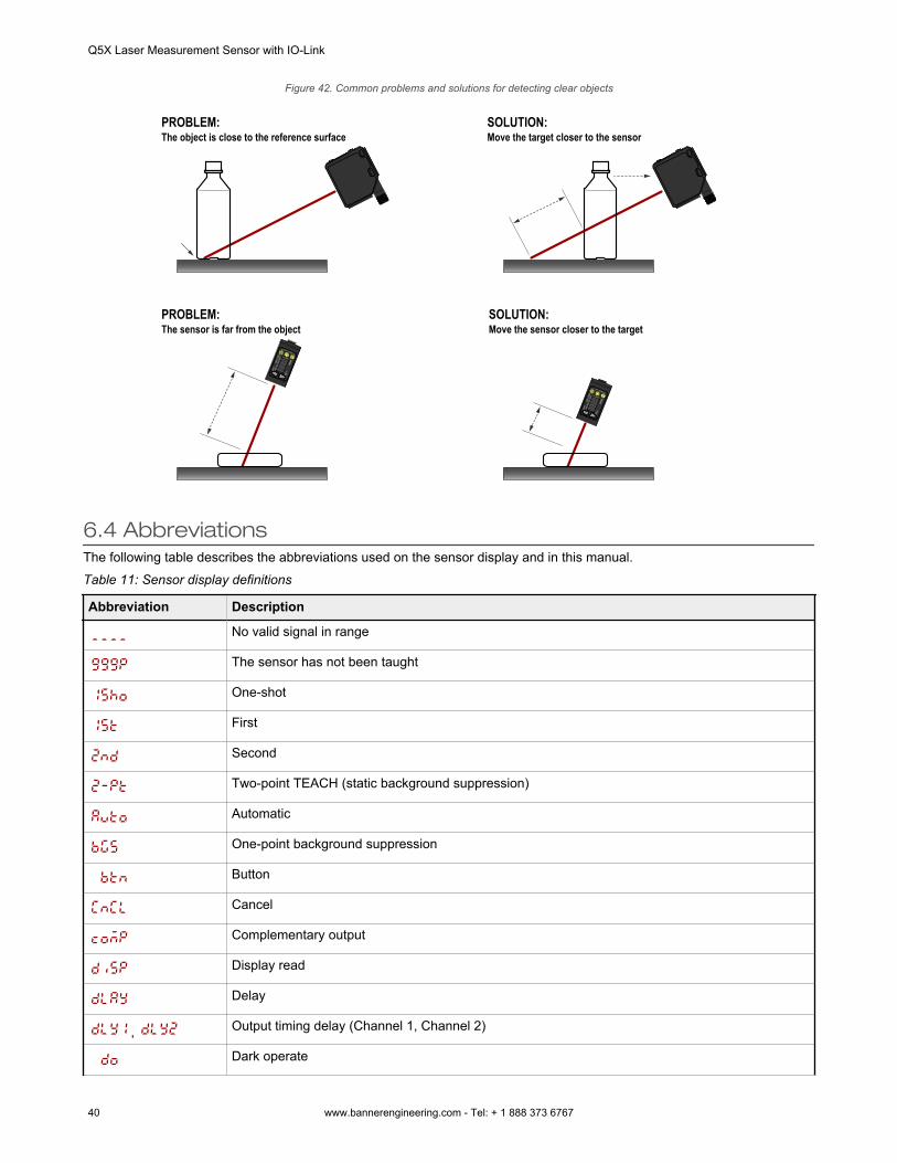
Figure 42. Common problems and solutions for detecting clear objects
The object is close to the reference surfacePROBLEM:
Move the target closer to the sensorSOLUTION:
CC CC
The sensor is far from the objectPROBLEM:
Move the sensor closer to the targetSOLUTION:
6.4 AbbreviationsThe following table describes the abbreviations used on the sensor display and in this manual.Table 11: Sensor display definitions
Abbreviation Description
No valid signal in range
The sensor has not been taught
One-shot
First
Second
Two-point TEACH (static background suppression)
Automatic
One-point background suppression
Button
Cancel
Complementary output
Display read
Delay
, Output timing delay (Channel 1, Channel 2)
Dark operate
Q5X Laser Measurement Sensor with IO-Link
40 www.bannerengineering.com - Tel: + 1 888 373 6767
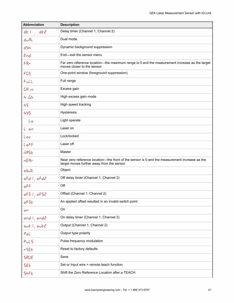
Abbreviation Description
, Delay timer (Channel 1, Channel 2)
Dual mode
Dynamic background suppression
End—exit the sensor menu
Far zero reference location—the maximum range is 0 and the measurement increase as the targetmoves closer to the sensor
One-point window (foreground suppression)
Full range
Excess gain
High excess gain mode
High speed tracking
Hysteresis
Light operate
Laser on
Lock/locked
Laser off
Master
Near zero reference location—the front of the sensor is 0 and the measurement increase as thetarget moves further away from the sensor
Object
, Off delay timer (Channel 1, Channel 2)
Off
, Offset (Channel 1, Channel 2)
An applied offset resulted in an invalid switch point
On
, On delay timer (Channel 1, Channel 2)
, Output (Channel 1, Channel 2)
Output type polarity
Pulse frequency modulation
Reset to factory defaults
Save
Set or Input wire = remote teach function
Shift the Zero Reference Location after a TEACH
Q5X Laser Measurement Sensor with IO-Link
www.bannerengineering.com - Tel: + 1 888 373 6767 41
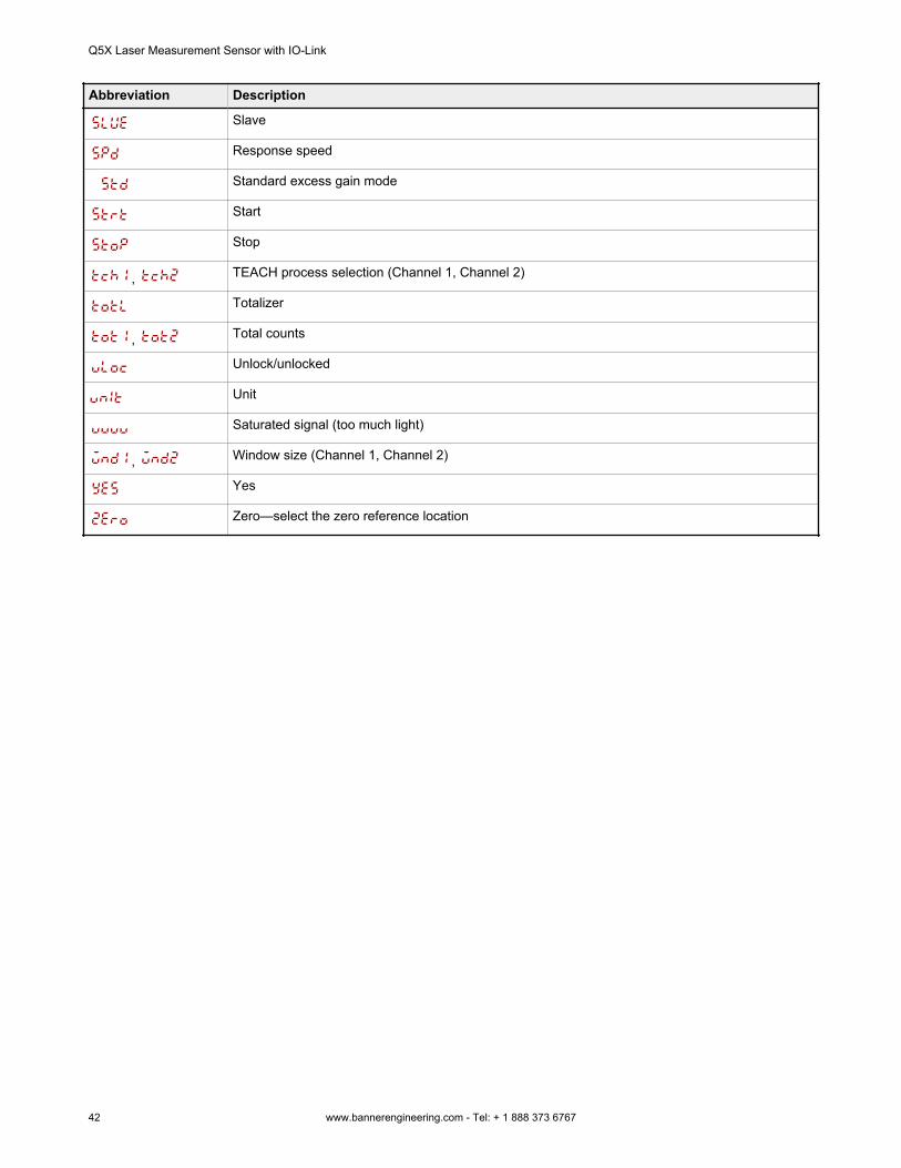
Abbreviation Description
Slave
Response speed
Standard excess gain mode
Start
Stop
, TEACH process selection (Channel 1, Channel 2)
Totalizer
, Total counts
Unlock/unlocked
Unit
Saturated signal (too much light)
, Window size (Channel 1, Channel 2)
Yes
Zero—select the zero reference location
Q5X Laser Measurement Sensor with IO-Link
42 www.bannerengineering.com - Tel: + 1 888 373 6767
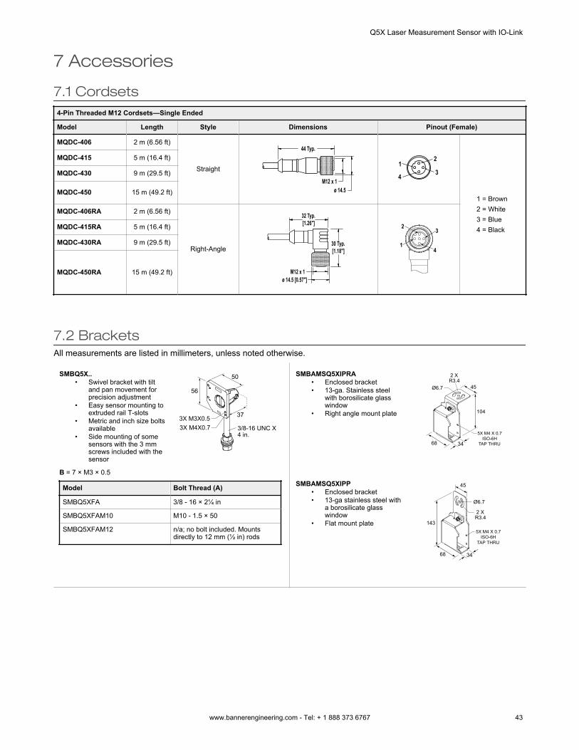
7 Accessories
7.1 Cordsets4-Pin Threaded M12 Cordsets—Single Ended
Model Length Style Dimensions Pinout (Female)
MQDC-406 2 m (6.56 ft)
Straight
44 Typ.
ø 14.5M12 x 1
2
34
1
1 = Brown2 = White3 = Blue4 = Black
MQDC-415 5 m (16.4 ft)
MQDC-430 9 m (29.5 ft)
MQDC-450 15 m (49.2 ft)
MQDC-406RA 2 m (6.56 ft)
Right-Angle
32 Typ.[1.26"]
30 Typ.[1.18"]
ø 14.5 [0.57"]M12 x 1
1
23
4
MQDC-415RA 5 m (16.4 ft)
MQDC-430RA 9 m (29.5 ft)
MQDC-450RA 15 m (49.2 ft)
7.2 BracketsAll measurements are listed in millimeters, unless noted otherwise.
SMBQ5X..• Swivel bracket with tilt
and pan movement forprecision adjustment
• Easy sensor mounting toextruded rail T-slots
• Metric and inch size boltsavailable
• Side mounting of somesensors with the 3 mmscrews included with thesensor
37
50
56
3/8-16 UNC X 4 in.
3X M3X0.53X M4X0.7
B = 7 × M3 × 0.5
Model Bolt Thread (A)
SMBQ5XFA 3/8 - 16 × 2¼ in
SMBQ5XFAM10 M10 - 1.5 × 50
SMBQ5XFAM12 n/a; no bolt included. Mountsdirectly to 12 mm (½ in) rods
SMBAMSQ5XIPRA• Enclosed bracket• 13-ga. Stainless steel
with borosilicate glasswindow
• Right angle mount plate
R3.42 X
68
45
104
34
Ø6.7
5X M4 X 0.7 ISO-6H
TAP THRU
SMBAMSQ5XIPP• Enclosed bracket• 13-ga stainless steel with
a borosilicate glasswindow
• Flat mount plateR3.42 X
68
143
45
34
Ø6.7
5X M4 X 0.7 ISO-6H
TAP THRU
Q5X Laser Measurement Sensor with IO-Link
www.bannerengineering.com - Tel: + 1 888 373 6767 43
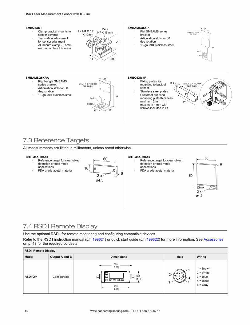
SMBQ5XDT• Clamp bracket mounts to
sensor dovetail• Translation adjustment
for sensor alignment• Aluminum clamp - 6.5mm
maximum plate thickness
M4 X 0.7 X 12mm
M4 X0.7 X 16 mm2X
20
20
14
SMBAMSQ5XP• Flat SMBAMS series
bracket• Articulation slots for 30
deg rotation• 13-ga. 304 stainless steel
143
68
5X M4 X 0.7 ISO-6H TAP THRU
2X R3.4
Ø6.5
SMBAMSQ5XRA• Right-angle SMBAMS
series bracket• Articulation slots for 30
deg rotation• 13-ga. 304 stainless steel 104
68
5045
2X R3.4
Ø6.7
5X M4 X 0.7 ISO-6H TAP THRU
SMBQ5XM4F• Fixing plates for
mounting to back ofsensor
• Stainless steel plates• Customer supplied
mounting plate thicknessminimum 2 mmmaximum 4 mm withscrews included in kit
M4 X 0.7 ISO-6H TAP THRU
25
83.4
7.3 Reference TargetsAll measurements are listed in millimeters, unless noted otherwise.
BRT-Q4X-60X18• Reference target for clear object
detection or dual modeapplications
• FDA grade acetal material
2 xø4.5
186
60 BRT-Q4X-60X50• Reference target for clear object
detection or dual modeapplications
• FDA grade acetal material
2 xø4.6
50
6
60
7.4 RSD1 Remote DisplayUse the optional RSD1 for remote monitoring and configuring compatible devices.Refer to the RSD1 instruction manual (p/n 199621) or quick start guide (p/n 199622) for more information. See Accessorieson p. 43 for the required cordsets.
RSD1 Remote Display
Model Output A and B Dimensions Male Wiring
RSD1QP Configurable
78.0[3.07]
68.0[2.68]
28.0[1.10]
1
453
21 = Brown2 = White3 = Blue4 = Black5 = Gray
Q5X Laser Measurement Sensor with IO-Link
44 www.bannerengineering.com - Tel: + 1 888 373 6767
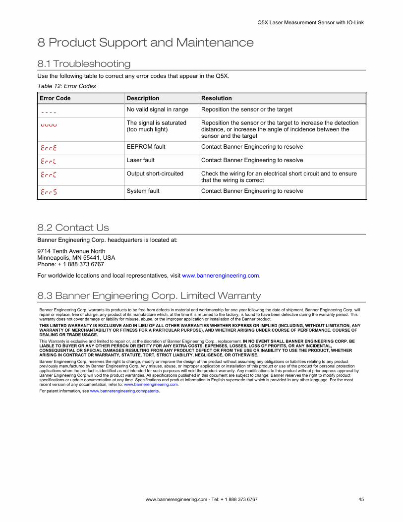
8 Product Support and Maintenance
8.1 TroubleshootingUse the following table to correct any error codes that appear in the Q5X.Table 12: Error Codes
Error Code Description Resolution
No valid signal in range Reposition the sensor or the target
The signal is saturated(too much light)
Reposition the sensor or the target to increase the detectiondistance, or increase the angle of incidence between thesensor and the target
EEPROM fault Contact Banner Engineering to resolve
Laser fault Contact Banner Engineering to resolve
Output short-circuited Check the wiring for an electrical short circuit and to ensurethat the wiring is correct
System fault Contact Banner Engineering to resolve
8.2 Contact UsBanner Engineering Corp. headquarters is located at:
9714 Tenth Avenue NorthMinneapolis, MN 55441, USAPhone: + 1 888 373 6767
For worldwide locations and local representatives, visit www.bannerengineering.com.
8.3 Banner Engineering Corp. Limited WarrantyBanner Engineering Corp. warrants its products to be free from defects in material and workmanship for one year following the date of shipment. Banner Engineering Corp. willrepair or replace, free of charge, any product of its manufacture which, at the time it is returned to the factory, is found to have been defective during the warranty period. Thiswarranty does not cover damage or liability for misuse, abuse, or the improper application or installation of the Banner product.THIS LIMITED WARRANTY IS EXCLUSIVE AND IN LIEU OF ALL OTHER WARRANTIES WHETHER EXPRESS OR IMPLIED (INCLUDING, WITHOUT LIMITATION, ANYWARRANTY OF MERCHANTABILITY OR FITNESS FOR A PARTICULAR PURPOSE), AND WHETHER ARISING UNDER COURSE OF PERFORMANCE, COURSE OFDEALING OR TRADE USAGE.This Warranty is exclusive and limited to repair or, at the discretion of Banner Engineering Corp., replacement. IN NO EVENT SHALL BANNER ENGINEERING CORP. BELIABLE TO BUYER OR ANY OTHER PERSON OR ENTITY FOR ANY EXTRA COSTS, EXPENSES, LOSSES, LOSS OF PROFITS, OR ANY INCIDENTAL,CONSEQUENTIAL OR SPECIAL DAMAGES RESULTING FROM ANY PRODUCT DEFECT OR FROM THE USE OR INABILITY TO USE THE PRODUCT, WHETHERARISING IN CONTRACT OR WARRANTY, STATUTE, TORT, STRICT LIABILITY, NEGLIGENCE, OR OTHERWISE.Banner Engineering Corp. reserves the right to change, modify or improve the design of the product without assuming any obligations or liabilities relating to any productpreviously manufactured by Banner Engineering Corp. Any misuse, abuse, or improper application or installation of this product or use of the product for personal protectionapplications when the product is identified as not intended for such purposes will void the product warranty. Any modifications to this product without prior express approval byBanner Engineering Corp will void the product warranties. All specifications published in this document are subject to change; Banner reserves the right to modify productspecifications or update documentation at any time. Specifications and product information in English supersede that which is provided in any other language. For the mostrecent version of any documentation, refer to: www.bannerengineering.com.For patent information, see www.bannerengineering.com/patents.
Q5X Laser Measurement Sensor with IO-Link
www.bannerengineering.com - Tel: + 1 888 373 6767 45
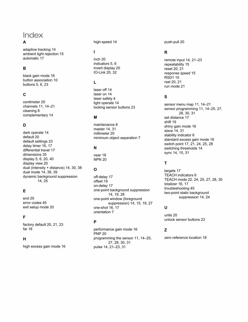
IndexAadaptive tracking 14ambient light rejection 15automatic 17
Bblack gain mode 16button association 10buttons 5, 6, 23
Ccentimeter 20channels 11, 14–21cleaning 8complementary 14
Ddark operate 14default 20default settings 23delay timer 16, 17differential travel 17dimensions 35display 5, 6, 20, 40display view 20dual (intensity + distance) 14, 30, 38dual mode 14, 38, 39dynamic background suppression
14, 25
Eend 20error codes 45exit setup mode 20
Ffactory default 20, 21, 23far 18
Hhigh excess gain mode 16
high-speed 14
Iinch 20indicators 5, 6invert display 20IO-Link 20, 32
Llaser off 14laser on 14laser safety 4light operate 14locking sensor buttons 23
Mmaintenance 8master 14, 31millimeter 20minimum object separation 7
Nnear 18NPN 20
Ooff-delay 17offset 19on-delay 17one-point background suppression
14, 19, 28one-point window (foreground
suppression) 14, 15, 19, 27one-shot 16, 17orientation 7
Pperformance gain mode 16PNP 20programming the sensor 11, 14–25,
27, 28, 30, 31pulse 14, 21–23, 31
push-pull 20
R
remote input 14, 21–23repeatability 15reset 20, 21response speed 15RSD1 10rset 20, 21run mode 21
S
sensor menu map 11, 14–21sensor programming 11, 14–25, 27,
28, 30, 31set distance 17shift 19shiny gain mode 16slave 14, 31stability indicator 6standard excess gain mode 16switch point 17, 21, 24, 25, 28switching thresholds 14sync 14, 15, 31
T
targets 17TEACH indicators 6TEACH mode 22, 24, 25, 27, 28, 30totalizer 16, 17troubleshooting 45two-point static background
suppression 14, 24
U
units 20unlock sensor buttons 23
Z
zero reference location 18


![0 IO-Link - ifmFile/151698O1D300.pdf · IO-Link Device "Laser Sensor” Ö1D300 to which this declaration refers conform to: [X] e IO-Link Interface and System Specification, V1.1,](https://img.pdfslide.net/doc/110x75/60196c04c7ee4574232cc503/0-io-link-ifm-file-io-link-device-laser-sensora-1d300-to-which-this.jpg)