Embed Size (px)
Citation preview

INSTALLATION MANUALVersion 3.OSecurity Products
TM
• W A R N I N G •Please refer to the System Installation Manual for information on limitations
regarding product use and function and information on the limitations as to liabilityof the manufacturer.

FCC COMPLIANCE STATEMENTCAUTION: Changes or modifications not expresslyapproved by Digital Security Controls Ltd. could voidyour authority to use this equipment.This equipment has been tested and found to comply withthe limits for a Class B digital device, pursuant to Part 15of the FCC Rules. These limits are designed to providereasonable protection against harmful interference in aresidential installation. This equipment generates, usesand can radiate radio frequency energy and, if not installedand used in accordance with the instructions, may causeharmful interference to radio communications. However,there is no guarantee that interference will not occur in aparticular installation. If this equipment does cause harmfulinterference to radio or television reception, which can bedetermined by turning the equipment off and on, the useris encouraged to try to correct the interference by one ormore of the following measures:• Re-orient the receiving antenna.• Increase the separation between the equipment andreceiver.• Connect the equipment into an outlet on a circuit differentfrom that to which the receiver is connected.• Consult the dealer or an experienced radio/televisiontechnician for help.The user may find the following booklet prepared by theFCC useful: “How to Identify and Resolve Radio/TelevisionInterference Problems”. This booklet is available from theU.S. Government Printing Office, Washington D.C. 20402,Stock # 004-000-00345-4.
IMPORTANT INFORMATIONThis equipment complies with Part 68 of the FCCRules. On the side of this equipment is a label thatcontains, among other information, the FCC registrationnumber of this equipment.NOTIFICATION TO TELEPHONE COMPANY Thecustomer shall notify the telephone company of theparticular line to which the connection will be made,and provide the FCC registration number and theringer equivalence of the protective circuit.FCC Registration Number: F53CAN-74349-KX-NFacility Interface Code: 02LS2Ringer Equivalence Number: 0.0BService Order Code: 9.0FUSOC Jack: RJ31X
TELEPHONE CONNECTION REQUIREMENTS Exceptfor the telephone company provided ringers, all connectionsto the telephone network shall be made through standardplugs and telephone company provided jacks, orequivalent, in such a manner as to allow for easy, immediate
disconnection of the terminal equipment. Standard jacksshall be so arranged that, if the plug connected theretois withdrawn, no interference to the operation of theequipment at the customer’s premises which remainsconnected to the telephone network shall occur byreason of such withdrawal.INCIDENCE OF HARM Should terminal equipment orprotective circuitry cause harm to the telephone network,the telephone company shall, where practicable, notifythe customer that temporary disconnection of servicemay be required; however, where prior notice is notpracticable, the telephone company may temporarilydiscontinue service if such action is deemed reasonablein the circumstances. In the case of such temporarydiscontinuance, the telephone company shall promptlynotify the customer and will be given the opportunity tocorrect the situation.ADDITIONAL TELEPHONE COMPANYINFORMATION The security control panel must beproperly connected to the telephone line with a USOCRJ-31X telephone jack.The FCC prohibits customer-provided terminalequipment be connected to party lines or to be used inconjunction with coin telephone service. Interconnectrules may vary from state to state.CHANGES IN TELEPHONE COMPANY EQUIPMENTOR FACILITIES The telephone company may makechanges in its communications facilities, equipment,operations or procedures, where such actions arereasonably required and proper in its business. Shouldany such changes render the customer’s terminalequipment incompatible with the telephone companyfacilities the customer shall be given adequate notice tothe effect modifications to maintain uninterrupted service.RINGER EQUIVALENCE NUMBER (REN) The REN isuseful to determine the quantity of devices that youmay connect to your telephone line and still have all ofthose devices ring when your telephone number iscalled. In most, but not all areas, the sum of the RENsof all devices connected to one line should not exceedfive (5.0). To be certain of the number of devices thatyou may connect to your line, you may want to contactyour local telephone company.EQUIPMENT MAINTENANCE FACILITY If youexperience trouble with this telephone equipment, pleasecontact the facility indicated below for information onobtaining service or repairs. The telephone companymay ask that you disconnect this equipment from thenetwork until the problem has been corrected or untilyou are sure that the equipment is not malfunctioning.Digital Security Controls Ltd.160 Washburn St., Lockport, NY 14094

1
CONTENTS
LINKS1000 GLOSSARY OF TERMS 2
INTRODUCING THE LINKS1000 3Specifications .................................................... 3
HOW THE LINKS1000 WORKS 4Cellular Communications .................................. 4Sending an alarm .............................................. 4Telephone Line Monitor .................................... 4Trouble supervision ........................................... 4Downloading ..................................................... 5Emergency Phone Number ............................... 5Powering the LINKS1000 from a DC Source .... 5Using the Keypad ............................................. 6
SETTING UP THE PROGRAMMER 6
LINKS1000 PROGRAMMING GUIDE 7Arranging for Cellular Service ........................... 7Using the LINKS1000 Programmer ................... 7Programming the LINKS1000 ........................... 8Disconnecting the LINKS1000 Programmer ..... 8
INSTALLATION 10Mounting the Cabinet ...................................... 10Mounting the Antenna ..................................... 10Wiring Connections ......................................... 10“AC” Power Terminals ..................................... 10Ground Connection ......................................... 11Tamper Terminal ............................................. 11Supervision of LINKS-to-Panel Connection .... 11LINKS SYS TBL Terminal ................................ 11AUX IN Terminal .............................................. 11LINKS PGMIn Terminal - Serial Input for CentralStation Telephone Number ............................. 11Telephone Terminals....................................... 12LINKS RING Terminal Allows Panel to beDownloaded via LINKS ................................... 12Bat TBL Terminal ............................................. 12AC TBL Terminal ............................................. 13Battery Connections ........................................ 13Jumper J1 ....................................................... 13Jumper J2 ....................................................... 13
HOOK-UP DIAGRAM -PC1500/1550/2525/2550/3000 14
HOOK-UP DIAGRAM - PC1575/PC1580/PC5010/PC5015/PC1555/PC1565/PC5008/PC580/PC585 15
HOOK-UP DIAGRAM -PC4010/PC4020/PC4020KT 16
HOOK-UP DIAGRAM -P16LC / P1664 / DC1664LC 17
RELOCATING THE ANTENNA 18
PROGRAMMING CONTROL PANELS FORLINKS1000 19
Preamble Section of Control PanelProgramming ................................................... 19Communication Formats ................................. 19PC1500 and PC1550 Control Panels .............. 20PC1575/PC1580 Control Panel ....................... 20PC2525 Control Panel ..................................... 20PC2550 Control Panel ..................................... 21PC3000 Control Panel ..................................... 21PC4010, PC4020 and PC4020KTControl Panels ................................................. 21PC5010/PC5015/PC1555/PC1565/PC5008/PC580/PC585 Control Panel ............. 23Sur-Gard DC1664LC ....................................... 24Sur-Gard P16LC .............................................. 24Sur-Gard P1664 .............................................. 25Power-up Procedure ....................................... 25
TESTING THE SYSTEM 25Performing a LINKS Test Transmission .......... 25“On Air” Indication .......................................... 2620-minute Transmission Cut-off ...................... 26
LINKS1000 TROUBLE SHOOTING 26
LINKS TROUBLE SUPERVISION 27Reading trouble conditions on the LINKS1000via the LINKS1000 Programmer ..................... 28
and are trademarks of the DSC Group of Companies.

2
LINKS1000 GLOSSARY OF TERMSThe following is a description of various terms used with regards to cellular technology.
Electronic Serial Number (ESN)The ESN is the unique serial number of a cellular phone. It is used by the cellular network to track calls andincrement billing. The ESN is stored at the time of manufacture and cannot be reprogrammed. This number,in either hexadecimal or decimal, must be loaded into the database of the cellular carrier before service canbegin.
Cellular Phone Number and Area CodeA 10 digit number (3 digit area code and 7 digit directory number ) identifying the cellular telephone. Do notenter the phone number of the central monitoring station as the cellular phone number when programmingthe LINKS1000.
Initial Paging ChannelA three digit number that specifies which ‘Side’ carrier you have contracted for service. Each cellular servicearea only has two sides, A or B. The initial paging channel for Side A is ‘333’ and for Side B is ‘334’.
System IDAlso called the Home Access ID, this 5 digit number identifies the customer's predefined ‘Home System’. Thisnumber refers to a geographic area and is used by the cellular carrier to determine if the unit is ‘Home’ or in‘Roam’.
Access Overload ClassThis is the number that specifies the level of priority of the cellular call. There is no correlation between thisnumber and the level of cellular service unless there is a network emergency.
Group Identification MarkThis number is factory programmed and specifies how many bits of the System ID are compared whenprocessing signals. The Group Mark ID for LINKS1000 is set at 10. This number will make the LINKS1000compatible with all North American networks.
Preferred System MarkThis number is determined by the Initial Paging Channel and refers to which system, A or B, is scanned forfirst.
Roam/RoamingUsing cellular service outside of one ‘Home’ area. Usage charges are higher when Roaming.

3
INTRODUCING THEThe LINKS1000 Cellular Alarm Transmitter enhances the protection provided by a security system byproviding a reliable backup to the control panel’s normal telephone communications with the monitoringstation. The LINKS1000 works with the DSC and Sur-Gard Security Control Panels described in theSpecifications below.If the control panel is unable to complete an alarm transmission through the normal telephone line, due to anyline problems, the LINKS1000 will be activated and will transmit the alarm communication over the cellularnetwork. The LINKS1000 works automatically.The LINKS1000 has been designed for simple and straightforward installation. Wiring connections are madedirectly between the LINKS unit and the security control panel. The DSC and Sur-Gard Security Control Panelsrequire only minor changes in their Programming Sections
SpecificationsCompatible control panels
• DSC PC1500/PC1550 software version 4.0 or later• DSC PC1575/PC1580 software version 1.0 or later• DSC PC2525 software version 1.0 or later• DSC PC2550 software version 1.2 or later• DSC PC3000 software version 7.6 or later• DSC PC4010 software version 1.0 or later• DSC PC4020 software version 1.0 or later• DSC PC4020KT software version 1.0 or later• DSC PC5010 software version 1.0 or later• DSC PC5015 software version 2.2 or later (w/Downlook)• DSC PC1555/PC1565/PC5008 software version 2.0 or later• DSC PC580/PC585 software version 2.1 or later• Sur-Gard DC1664LC software version 3.6 or later (requires MEX2 Module)• Sur-Gard P16LC and P1664LC software versions 2.0 or laterUL has only verified compatibility with the PC4020 and PC5010.
Communication Method• Amps cellular telephone network
RF Power Output• 3.0 Watts maximum
Antenna• 3 - 5 dB gain, TNC connector
Battery• 12 volt 7 Ah minimum rechargeable gel-cell type battery
Transformer• 16.5 VAC, 40 VA
Dimensions• 11" × 11.8" × 3.3" (279 mm × 300 mm × 84 mm)
Weight• 6.5 lbs. (3 kg)
IMPORTANT NOTEA security system cannot prevent emergencies. It is only intended to alert you and, if included, a monitoringstation, of an emergency situation. Security systems are generally very reliable but they may not work underall conditions and they are not a substitute for prudent security practices or life and property insurance. Yoursecurity system should be installed and serviced by qualified security professionals who should instructyou on the level of protection that has been provided and on system operations.
4
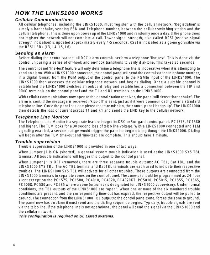
HOW THE LINKS1000 WORKSCellular Communications
All cellular telephones, including the LINKS1000, must ‘register’ with the cellular network. ‘Registration’ issimply a handshake, sending ESN and Telephone number, between the cellular switching station and thecellular telephone. This is done upon power up of the LINKS1000 and randomly once a day. If the phone doesnot register the network will not complete a call. Tower signal strength, also called RSSI (receive signalstrength indication) is updated approximately every 4-5 seconds. RSSI is indicated as a go/no go visible viathe RSSI LEDs (L3, L4, L5, L6).
Sending an alarmBefore dialing the central station, all DSC alarm controls perform a telephone ‘line-test’. This is done via thecontrol unit using a series of off-hook and on-hook transitions to verify dial-tone. This takes 30 seconds.
The control panel ‘line-test’ feature will only determine a telephone line is inoperative when it is attempting tosend an alarm. With a LINKS1000 connected, the control panel will send the central station telephone number,in a digital format, from the PGM output of the control panel to the PGMIn input of the LINKS1000. TheLINKS1000 then accesses the cellular telephone network and begins dialing. Once a suitable channel isestablished the LINKS1000 switches an onboard relay and establishes a connection between the TIP andRING terminals on the control panel and the T1 and R1 terminals on the LINKS1000.
With cellular communications now open to the central station receiver, the panel will detect ‘handshake’. Thealarm is sent. If the message is received, ‘kiss-off’ is sent, just as if it were communicating over a standardtelephone line. Once the panel has completed the transmission, the control panel ‘hangs up’. The LINKS1000then detects the loss of current across T1 and R1 and sends the END key to the cellular network.
Telephone Line MonitorThe Telephone Line Monitor is a separate feature integral to DSC or Sur-gard control panels PC1575, PC1580and higher. The TLM looks for a 30 second loss of telco line voltage. With a LINKS1000 connected and TLMsignaling enabled, a service outage would trigger the panel to begin dialing though the LINKS1000. Dialingwill begin after the TLM time-out and ‘line-test’ are complete. This should take 1 minute.
Trouble supervisionTrouble supervision of the LINKS1000 is provided in one of two ways:When Jumper J1 is ON (shorted), a general system trouble indication is used at the LINKS1000 SYS TBLterminal. All trouble indications will trigger this output to the control panel.When Jumper J1 is OFF (removed), there are three separate trouble outputs: AC TBL, Bat TBL, and theLINKS1000 SYS TBL. The AC TBL terminal and Bat TBL terminals are each used to indicate their respectivetroubles. The LINKS1000 SYS TBL will activate for all other troubles. These outputs are connected from theLINKS1000 terminals to separate zones on the control panel. The zone(s) should be programmed as 24-hoursilent except on the PC1575, PC1580, PC4010, PC4020, PC4020KT, PC5010, PC5015, PC1555, PC1565,PC5008, PC580 and PC585 where a zone (or zones) is designated for LINKS1000 supervisory. Under normalconditions, the TBL outputs of the LINKS1000 are “open”. When one or more of the six monitored troubleconditions are present, and the corresponding time-out has expired, the respective output will be pulled toground. The connection from the LINKS1000 TBL output to the control panel zone, forces the zone to ground.The panel now has an alarm it must send and the dialing sequence begins. Typically, trouble signals are sentvia the telco line. If the telephone line is not operational, the panel will send the signal via the LINKS1000 andthe cellular network.This configuration is required on UL Listed systems.

5
DownloadingDownloading an alarm control via the LINKS1000 requires connecting the RING terminal on the LINKS1000to the proper terminal on the control panel (see instructions). Then, from the downloading computer, simplydial the cellular telephone number of the LINKS1000. The LINKS detects an incoming call and pulls the RINGterminal to 12 VDC. This instructs the alarm control to answer, the panel then provides continuity across TIPand RING. The LINKS detects current flow and connects the LINKS T1 and R1 and the panel TIP and RING.Upon completion of downloading, the LINKS1000 will ‘hang up’. The LINKS1000 will automatically disconnectany call after a 20 minute duration.
Emergency Phone NumberThis number is programmed into the LINKS1000 and will be dialed when the AUX IN terminal is shorted toground. To program the number, enter the emergency phone number into the LINKS1000, exactly as it wouldbe dialed on a cellular phone. To use this feature, place an ordinary handset in parallel with the panel on theLINKS1000 T-1, R-1 terminals and connect a normally open pushbutton across the AUX IN and Groundterminals.
NOTE: This input is a 24-hour, silent terminal and the Panic phone call will be connected through the cellularnetwork.
Powering the LINKS1000 from a DC SourceThe LINKS1000 (v3.0 and higher) has the capability to be powered only by a DC source. This could be usefulin such applications as: large recreational vehicles, motor homes, transport trucks, large boats, etc. In thesecases, the main power source is the vehicle’s battery and DC electrical system with no true AC source for thecontrol panel or LINKS1000 to draw power from.
To use the LINKS1000 with only a DC source, short jumper J2 and leave in place. Connect all wiring for theLINKS1000 except for the power circuit. Once all connections are made, connect the vehicle’s DC source tothe battery leads of the LINKS1000 (observing correct polarity) and test the control panel and LINKS1000according to the “Testing the System” sections of their respective manuals.
NOTE: If the LINKS1000 is being used for such an application, the central station should be notified when thevehicle is being serviced to avoid possible false alarms.
NOTE: The LINKS1000, control panel and DC source should be in a physically secure location to avoidpossible tampering.
This configuration should not be used on UL Listed systems.

6
SETTING UP THE PROGRAMMERInstall 4 AA batteries in the LINKS1000 Programmer, being sure to note proper orientation. If the batteries areinstalled incorrectly, the Programmer will not function.
Using the KeypadOperation of the Programmer is as simple as scrolling through the menu to find the desired programmingoption and pressing the [] Key to select the option.
•Use the and keys to scroll through the menu displays to locate the desired menu or programming item•When the screen displays the desired menu item or programming option, press the [] Key to select the
item or option•The Programmer will automatically shut itself off if there is no keypad activity for a period of 2 minutes.
NOTE: The LINKS1000 will not function until the Programmer is unplugged from it.
Programmer Low Battery IndicationIf the Programmer’s batteries begin to run low, this message will be displayed:
* PROGRAMMER *
* LOW BATTERY *
The low battery message will remain on the screen for 3 seconds or until it is acknowledged by pressing anykey while it is displayed. If a key is pressed while the message is displayed, the message will not reappearfor the rest of the programming session.
If the message is not acknowledged, it will be removed from the screen after 3 seconds; the next time a keyis pressed, the low battery message will again be displayed.
Connect cable to LINKS1000programming jack.

7
Arranging for Cellular ServiceIn order for the LINKS1000 to communicate via the cellular telephone network, an account must be set up witha cellular network operator. The ‘account’ is simply a matter of establishing the billing information for thecellular service. In return, the cellular carrier will provide you with the cellular telephone number. Cellularservice may vary in price and coverage. Check with your cellular service provider for area coverage mapsand service charges.
Any cellular telephone service provider may be used as the LINKS1000 is compatible with all AMPS typecellular telephone networks. There are a maximum of two separate network operators in a given market. Theyare called non-wireline carriers (A-Side) and wireline carriers (B-Side). Choose the carrier and rate plan thatbest fits the application.
DSC is not a cellular service provider, however the LINKS1000 is licensed to use the ‘HELPTEL’ cellularservice rate offered by LINDSAY Communications of Loeminster, Massachusetts. This coverage is virtuallynation wide, using exclusively A-side carriers, and offers service rates that are designed for cellularapplications requiring minimal air time. (In most applications the LINKS1000 is configured to activate onlywhen the alarm is set and the protected premises experiences an unanticipated loss of dial tone.) LINDSAYCommunications can be reached at 1-800-878-9898. For answers to any other questions concerning cellularactivation call 1-800-355-3630.
Note: When using LINDSAY Communication for cellular service, pay close attention to the PREAMBLESection when programming the control panel.
Using the LINKS1000 ProgrammerThe LINKS1000 Programmer is used to enter the required cellular network parameters into the LINKS1000.If the parameters are not entered correctly, the LINKS1000 will not operate.
AC power must be applied to the LINKS1000 in order to program any data.Connect the modular connector of the Programmer to the modular jack on the LINKS1000. Press any key toactivate the Programmer. The LCD screen will light up.
Note: If the screen does not light up, check to see if 4 AA batteries were correctly installed in the back ofthe Programmer.
The LINKS1000 Programmer is menu driven (see Table 1 for a list of menu messages):• use ‘up’ and ‘down’ arrows to scroll through the various menu fields• when the desired field is displayed, use the [] key to select it• or use the numbers shown in parentheses to go directly to the desired menu or item• use the [#] key to enter data and exit the section.
Before a cellular service provider will give the Cellular Phone parameters, you must first give the LINKS1000Electronic Serial Number (ESN). The ESN is found on the LINKS itself (in hexadecimal), or can be read via theProgrammer (in hexadecimal).
If the ESN was not found on the LINKS1000, scroll to the “Read LINKS” menu. Select the ESN and the LCDwill display the ESN in hexadecimal form.
Record the ESN here: l_____l_____l - l_____l_____l_____l_____l_____l_____l
The following parameters must be obtained from the Cellular carrier:
• The cellular telephone number for the LINKS l_____l_____l_____l -l_____l_____l_____l -l_____l_____l_____l_____l
• The System I.D. l_____l_____l_____l_____l_____l
• The Initial Paging Channel l_____l_____l_____l
LINKS1000 PROGRAMMING GUIDE

8
Programming the LINKS1000Step 1. Programming the Cellular Telephone Number
Scroll to “Write LINKS” and press [] to select. Scroll to “LINKS Phone #” and press [] to select.Enter the area code and phone number for the LINKS. Press [#] to store and exit.
Step 2. Program the Cellular Network ParametersWhile still in “Write LINKS” menu, scroll to “System I.D.” and press [] to select. Enter the five digitSystem I.D. number. Press [#] to store and exit.Scroll to the “Initial Page” and press [] to select. Choose either “A SIDE 333” or “B SIDE 334” usingthe and keys. Press [#] to store and exit.Scroll to “Access Class” and press [] to select. (This is automatically set by the Programmer.)Press [#] to store and exit.
Step 3. Enabling DownloadingWhile still in the “Write LINKS” menu, scroll to “Downloading?” and press [] to select. Using theand keys, choose either “Enabled” or “Disabled”. Press [#] to store and exit.Only LINKS1000 version 2.10 or higher will support this function. This option will display onnon-supported versions, but will not be accessible.
NOTE: With the Downloading feature “Enabled,” the LINKS1000 will answer ANY call placed to theLINKS1000 cellular telephone number, therefore generating cellular charges. If Downloading via theLINKS1000 will not be used, the Downloading feature must be disabled.
Step 4. AC Failure Reporting OptionThe option of sending an AC failure is done via the AC Failure reporting display. Scroll to the ‘ACTbl Sent?’ screen and press []. Press the and keys to toggle either ‘Enable’ or ‘Disable’.Press [#] to store and exit.With the option ‘Enabled’ the LINKS1000 WILL report loss of AC power.With the option ‘Disabled’ the LINKS1000 WILL NOT report loss of AC power.Only LINKS1000 version 2.20 or higher will support this function. This option will display onnon-supported versions, but will not be accessible.
Step 5. Emergency Phone NumberThe AUX IN terminal provides a Panic type alarm to the LINKS1000. When this terminal is briefly shortedto ground, the LINKS1000 will dial the phone number that is programmed in the emergency phonenumber location.Only LINKS1000 version 3.0 or higher will support this function. This option will display onnon-supported versions, but will not be accessible.
NOTE: This input is a 24-hour, silent terminal and the Panic phone call will be connected through thecellular network.Select the LINKS Write menu, then select the Emergency Phone Number item.Enter the phone number exactly as it would be dialed on a standard cellular phone. Press [#] toexit the item and store the phone number into the LINKS1000 memory. (See “How the LINKS1000Works” for instructions on how to connect a phone to the LINKS1000 for use with the emergencyphone number.)
Disconnecting the LINKS1000 ProgrammerStep 1. Scroll to “Main Menu”.Step 2. Press [#], wait for the display to go blank.Step 3. Disconnect the modular cord from the LINKS1000. DoneNOTE: Unplug the Programmer from the LINKS1000 when finished programming. The LINKS1000 will notoperate when the Programmer is plugged in.

9
Table 1 — List of LINKS1000 Programmer Menu Messages
Main Menu
(0) Write LINKS (1) Trouble (2) Read LINKS
(0) LINKS Phone # (0) LINKS Phone #
(1) System I.D. (1) ESN
(2) Initial Page (2) System I.D.
(3) Access Class (3) Initial Page
(4) Downloading (4) Access Class
(5) AC TBL Sent (5) Group ID Mark
(6) Emergency Phone # (6) Prefrd Sys Mark
(7) Downloading
(8) AC TBL Sent
(9) Emergency Phone #
See Table 3 on page 28for Trouble Messages
and explanations

10
INSTALLATIONMounting the Cabinet
It is important to mount the LINKS1000 as close to the DSC / Sur-gard alarm control panel as possible .3 feet is the recommended maximum distance between the two devices. If the devices are mounted in anunder-over arrangement, always mount the LINKS1000 on top. It is recommended that all wiring between thecontrol panel and the LINKS1000 be in a tamper and attack-resistant conduit.Keep in mind the LINKS1000 antenna must be mounted above ground level . If necessary, AntennaExtension Kits are available from your distributor. Remember cellular likes height. The antenna should beinstalled in a physically secured location to avoid tampering.As much as reasonably possible the LINKS1000 should not be located near sources of interference. These sourcesinclude EMI generated by televisions or heavy electric motors such as those found in heating or air conditioning units.Remove printed circuit board and wall mounting hardware from cardboard retainer inside cabinet. Before attachingthe cabinet to the wall, press the white nylon mounting studs through the holes in the back of the cabinet.
Mounting the AntennaNOTE: An antenna should always be connected to the LINKS1000 whenever it is operated. The unit will notfunction properly if an antenna is not installed.
Before attaching the antenna, first secure the TNC connector and cable attached to the LINKS unit in the holein the top of the cabinet using the hardware provided. Ensure the star washers make solid electrical contactwith the metal cabinet; refer to the illustrations below.
The antenna should be mounted as high above ground level as possible while at the same time taking care notto place the antenna under a Radio Frequency shield of any kind. I.E. do not mount the antenna directly beneatha metal roofing over hang. Cellular works best when in an unobstructed “line of sight” to the cellular antenna site.
Wiring Connections
Do not connect the transformer or battery until all other wiring, including the antenna connection, has beencompleted and checked. Incorrect wiring connections may cause the LINKS1000 unit to operate improperly.
“AC” Power TerminalsFor proper operation, the LINKS1000 requires its own transformer. Do not use the control panel transformerto power the LINKS1000. Do not connect the transformer or battery until all other wiring is complete. Use a16.5 VAC transformer with a minimum 40 VA rating to supply AC power to the LINKS1000. Do not connect thetransformer to an outlet that is controlled by a switch. UL Listed systems should employ the ATC-Frost PINFTC3716 transformer.Note: All terminals are power limited except for the battery leads. All power limited wiring shall beinstalled using FPL, FPLR, FPLP or permitted substitute cable.”

11
Ground ConnectionConnect the LINKS “AUX-GND” terminal to the control panel “GND” terminal. AUX- or KEYPAD BLACK and ZONECOMMON are also good ground connections. A good ground connection is essential for proper operation.Connect a ground cable from the Cabinet Ground connection to an earth ground, such as a copper cold waterpipe, by the shortest and most direct route. Ensure that the cold water pipe connection provides path to ground.Do not make the ground connection to a plastic cold water pipe!
Tamper TerminalThe “TMP” terminal on the LINKS1000 is provided for a cabinet tamper switch. If a tamper switch is not used,then a wire jumper must be connected between the “TMP” and “GND” terminals.
Supervision of LINKS-to-Panel ConnectionTo make use of the cable tamper alarm simply connect an end-of-line resistor, of the value indicated on thehook-up diagram, across the GND terminal and the LINKS SYS TBL terminal. If the cable between the LINKSand the control panel is cut, a fault will be presented to the LINKS1000 supervisory zone.NOTE: Resistor must be installed in LINKS cabinet.Resistor must be installed in LINKS cabinet.Resistor must be installed in LINKS cabinet.Resistor must be installed in LINKS cabinet.Resistor must be installed in LINKS cabinet.
LINKS SYS TBL TerminalWhen jumper J1 is shorted, this terminal is used to report all troubles to the attached control panel, includingthe AC and Battery troubles. The AC TBL and BAT TBL terminals will be disabled when J1 is shorted.When jumper J1 is open, the AC TBL and BAT TBL will be reported at their respective terminals. All othertroubles will be reported through the LINKS SYS TBL terminal.The LINKS SYS TBL terminal will switch to ground whenever a trouble condition is present on the LINKS unit. Theterminal will remain switched to ground for as long as a trouble condition exists. This feature is used to report LINKStrouble conditions through the control panel via a zone programmed for LINKS Supervision (see programmingguide for instructions). Also, when a resistor is connected across GND of the LINKS and the SYS TBL of the LINKS,then connected to the designated LINKS supervision zone, the control panel will report an open in the connectionbetween the LINKS and the control panel (see instructions for correct resistor value).When using Normally Closed Loops, connect a DSC Model RM-1 Relay to the control panel and the LINKSas described below. The Alarm and Reporting Codes programmed for the zone connected to the yellow leadof the RM-1 will be used to report a general trouble and restore on the LINKS. Note that the PC5010, PC5015,PC1555, PC1565, PC5008, PC580, PC585, PC4010, PC4020 and PC4020KT always use an end-of-lineresistor regardless of how zone supervision is programmed.
RM-1 Lead ConnectionYellow Control Panel Zone terminalWhite Control Panel COM terminalRed Control Panel AUX terminal
Black LINKS PGM terminalGreen No connection
AUX IN TerminalWhen this terminal is temporarily shorted to ground, the LINKS1000 will dial the phone number that isprogrammed in the emergency phone number position. This phone number has to be a direct access line, itcan not be dialed to a PBX and then into an extension.NOTE: This input is a 24-hour, silent terminal and the Panic phone call will be connected through the cellular network.If this input is triggered, the panel will be disconnected from the cellular network. Please use this input carefully.
LINKS PGMIn Terminal - Serial Input for Central Station Telephone NumberThe connection between the control panel PGM and the LINKS1000 PGMIn is very important. It carries thetelephone number of the central station to LINKS, the LINKS then dials that number through the cellular network.The PC 1550, PC4010, PC4020 and PC4020KT require a 1K ohm resistor connected between the control panelPGM and the AUX+. The PC1575, PC1580, PC5010, PC1555, PC1565, PC5015, PC5008, PC580, PC585,P16LC and P1664 require a 5.6K ohm resistor. The PC2525, PC2550, PC3000 do not require a resistor acrossPGM and AUX+. For PC4010/PC4020 software version 3.0 and up, connect a 5600ohm resistor between thecontrol panel AUX- and PGM terminals. Refer to hook up diagram in this manual.The maximum distance (wire length) the LINKS should be mounted from the control panel is 3 feet.

12
DC1664LCConnect the LINKS PGMIn terminal to the PGM 9 terminal on the MEX2 module installed with the DC1664LC.A 500 ohm resistor must be connected to GND between the PGM 9 and LINKS PGMIn terminals. Referto the Hook-Up Diagram in this manual.
Telephone TerminalsFrom an RJ31-X plug, make the following connections:
Conductor from RJ31-X Plug ConnectionRED LINKS RING terminalGRN LINKS TIP terminalGRY control panel R-1 terminalBRN control panel T-1 terminal
Also, connect the following jumpers between the LINKS and control panel:Control Panel LINKS
TIP ............................................................. T-1RING ........................................................... R-1
LINKS RING Terminal Allows Panel to be Downloaded via LINKS Whenever the LINKS phone number is called, the RING terminal will activate. This feature may be used tomake the control panel answer an incoming call via the cellular telephone network.
PC1500 and PC1550Connect the LINKS RING terminal to the control panel’s Zone 6 terminal. When LINKS operation is enabledin Programming Section [24], Zone 6 will be automatically configured for LINKS operation.
If the control panel is programmed for End-of-Line Resistor zones (see Section [12] Zone Light 5), connect a1000Ω resistor between the LINKS1000 RING terminal and the control panel Zone 6 terminal. If the controlpanel is programmed for normally-closed zones, do not connect a resistor between these terminals.
PC1575 and PC1580PGM2 configured for LINKS Answer allows downloading to be performed in the event of phone line failure.When the LINKS receives a phone call, it will activate the RING terminal on the LINKS circuit board. The PGM2programmed as LINKS answer always requires a 2200 ohm resistor. The LINKS answer zone must be wiredwith a RM-1 relay as shown in the hook-up diagram.
PC2550 and PC3000Connect the LINKS RING terminal to the control panel’s AUX input to provide a forced answer for downloadingpurposes. Refer to the “Programming” section of this manual for information on programming the PC2550 andPC3000 control panels to enable the “forced answer” option.
PC2525Connect the LINKS RING terminal to an available zone terminal on the control panel. Refer to the“Programming” section of this manual for information on programming the zone for the “LINKS Answer” option.If the PC2525 is programmed for End-of-Line Resistor zones (see Section [8] Zone Light 1), connect a 5.6K ohmresistor between the LINKS1000 RING terminal and the PC2525 zone terminal programmed as “Forced Answer”.If the PC2525 is programmed for normally-closed zones, do not connect a resistor between these terminals.
PC5010, PC5015, PC1555, PC1565, PC5008, PC580, PC585, PC4010, PC4020, PC4020KT, P16LC,P1664 and DC1664LC
Connect the LINKS RING terminal to an available zone terminal on the control panel. Refer to the “Programming”section of this manual for information on programming the zone for the “LINKS Answer” option.
13
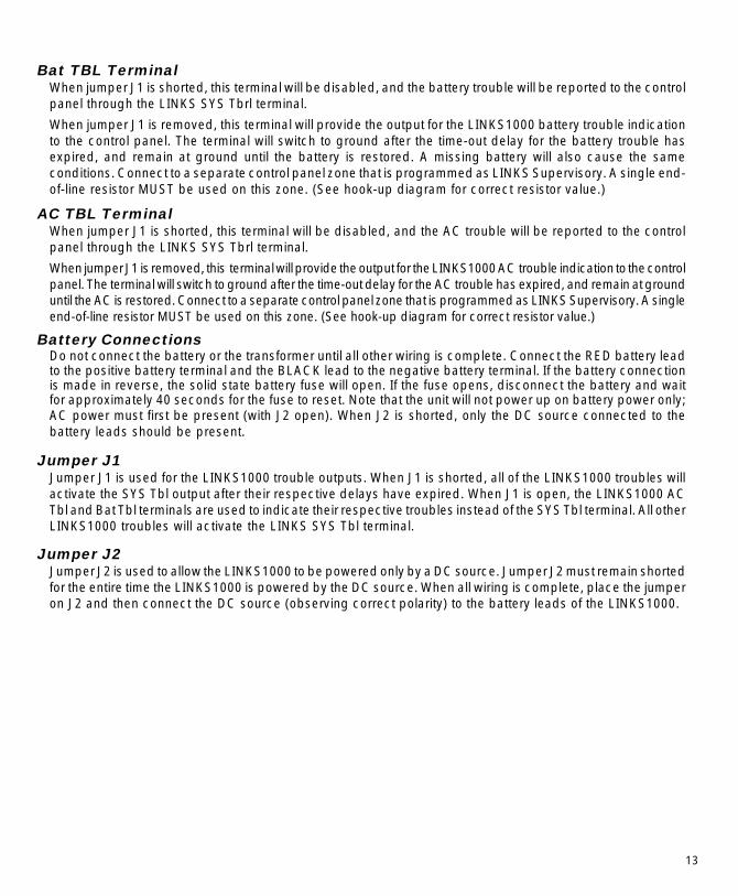
Bat TBL TerminalWhen jumper J1 is shorted, this terminal will be disabled, and the battery trouble will be reported to the controlpanel through the LINKS SYS Tbrl terminal.
When jumper J1 is removed, this terminal will provide the output for the LINKS1000 battery trouble indicationto the control panel. The terminal will switch to ground after the time-out delay for the battery trouble hasexpired, and remain at ground until the battery is restored. A missing battery will also cause the sameconditions. Connect to a separate control panel zone that is programmed as LINKS Supervisory. A single end-of-line resistor MUST be used on this zone. (See hook-up diagram for correct resistor value.)
AC TBL TerminalWhen jumper J1 is shorted, this terminal will be disabled, and the AC trouble will be reported to the controlpanel through the LINKS SYS Tbrl terminal.
When jumper J1 is removed, this terminal will provide the output for the LINKS1000 AC trouble indication to the controlpanel. The terminal will switch to ground after the time-out delay for the AC trouble has expired, and remain at grounduntil the AC is restored. Connect to a separate control panel zone that is programmed as LINKS Supervisory. A singleend-of-line resistor MUST be used on this zone. (See hook-up diagram for correct resistor value.)
Battery ConnectionsDo not connect the battery or the transformer until all other wiring is complete. Connect the RED battery leadto the positive battery terminal and the BLACK lead to the negative battery terminal. If the battery connectionis made in reverse, the solid state battery fuse will open. If the fuse opens, disconnect the battery and waitfor approximately 40 seconds for the fuse to reset. Note that the unit will not power up on battery power only;AC power must first be present (with J2 open). When J2 is shorted, only the DC source connected to thebattery leads should be present.
Jumper J1Jumper J1 is used for the LINKS1000 trouble outputs. When J1 is shorted, all of the LINKS1000 troubles willactivate the SYS Tbl output after their respective delays have expired. When J1 is open, the LINKS1000 ACTbl and Bat Tbl terminals are used to indicate their respective troubles instead of the SYS Tbl terminal. All otherLINKS1000 troubles will activate the LINKS SYS Tbl terminal.
Jumper J2Jumper J2 is used to allow the LINKS1000 to be powered only by a DC source. Jumper J2 must remain shortedfor the entire time the LINKS1000 is powered by the DC source. When all wiring is complete, place the jumperon J2 and then connect the DC source (observing correct polarity) to the battery leads of the LINKS1000.

14
HOOK-UP DIAGRAM - PC1500/1550/2525/2550/3000
NOTES
1 An AC power supply must be dedicatedto the LINKS1000. Do not use thesecurity system's transformer to powerthe LINKS1000.
2 The LINKS1000 should be mounted asclose as possible to the control panelto minimize the length of the wiringbetween the LINKS1000 and the controlpanel (max. 3ft apart).
3 Depending on the securityrequirements of the installation, theconnections between the LINKS1000and the control panel may need to beprotected in a damage and tamperresistant conduit. Knockout locationsare provided on both the LINKS1000cabinet and the control panel cabinetfor wiring between the cabinets and forthe fitting of protective conduits.

15
HOOK-UP DIAGRAM - PC1575/PC1580/PC5010/PC5015/PC1555/PC1565/PC5008/PC580/PC585
NOTES
1 An AC power supply must be dedicatedto the LINKS1000. Do not use the securitysystem's transformer to power theLINKS1000.
2 The LINKS1000 should be mounted asclose as possible to the control panel tominimize the length of the wiring betweenthe LINKS1000 and the control panel(max. 3ft apart).
3 Depending on the security requirementsof the installation, the connectionsbetween the LINKS1000 and the controlpanel may need to be protected in adamage and tamper resistant conduit.Knockout locations are provided on boththe LINKS1000 cabinet and the controlpanel cabinet for wiring between thecabinets and for the fitting of protectiveconduits. This configuration isrequired on UL Listed systems.

16
HOOK-UP DIAGRAM - PC4010/PC4020/PC4020KT
NOTES
1 An AC power supply must be dedicated to the LINKS1000. Do not use the security system's transformer to power the LINKS1000.
2 The LINKS1000 should be mounted as close as possible to the control panel to minimize the length of the wiring between the LINKS1000and the control panel (max. 3ft apart).
3 Depending on the security requirements of the installation, the connections between the LINKS1000 and the control panel may need to beprotected in a damage and tamper resistant conduit. Knockout locations are provided on both the LINKS1000 cabinet and the control panelcabinet for wiring between the cabinets and for the fitting of protective conduits. This configuration is required on UL Listed systems.

17
HOOK-UP DIAGRAM - P16LC / P1664 / DC1664LC
NOTES
1 An AC power supply mustbe dedicated to theLINKS1000. Do not usethe security system'stransformer to power theLINKS1000.
2 The LINKS1000 shouldbe mounted as close aspossible to the controlpanel to minimize thelength of the wiringbetween the LINKS1000and the control panel(max. 3ft apart).
3 Depending on thesecurity requirements ofthe installation, theconnections between theLINKS1000 and thecontrol panel may needto be protected in adamage and tamperresistant conduit.Knockout locations areprovided on both theLINKS1000 cabinet andthe control panel cabinetfor wiring between thecabinets and for the fittingof protective conduits.

18
RELOCATING THE ANTENNA
Use only the Extension Kits to extend the mounting range of the antenna. Do not cut or splice theextension cable. The maximum distance between the LINKS and the antenna is 25 feet (7.62 m) as obtainedby using the LAE-25 Extension Kit. Make sure the antenna is in a physically secured location to avoid tampering.
Secure the TNC connector from the Extension Kit to the mounting bracket, ensuring that the star washers makesolid electrical contact with the mounting bracket.
Remove the antenna from the LINKS cabinet and connect the extension cable to the TNC connector on thecabinet. Secure the antenna to the TNC connector mounted on the Extension Kit Mounting Bracket.
Locate the mounting bracket and antenna away from possible sources of electrical interference. Moving theantenna just a short distance will likely be adequate. Temporarily secure the mounting bracket in the newlocation and repeat steps 1 - 3 above. If the test gives a good result, perform a test transmission as describedin the “Operations” section of this manual.
If the test is successful and the cellular transmission is completed without a Loss of Cellular Communicationtrouble, permanently secure the mounting bracket and antenna at the new location.
Before permanently mounting the LINKS1000 in it’s final location, verify that it is working as it should byfollowing these steps:Step 1: Make all connections between the LINKS and the control panel.Step 2: Power up the control panel and the LINKS1000.Step 3: Using the four LED’s on the upper left-hand side of the LINKS1000, find the position that gives theLINKS the best signal strength:
L3 (top, green LED) lit: indicates best received signal strength. Mount the LINKS here.L4 (second green LED) lit: indicates acceptable signal strength. The LINKS may be mounted here.L5 (yellow LED) lit: indicates poor signal strength. DO NOT mount the LINKS here as it will probably not
be able to communicate properly.L6 (red LED) lit: indicates very bad or no received signal strength. DO NOT mount LINKS here, as it will
not be able to communicate.If a suitable location is not available within the maximum 3ft wire length from the control panel, obtain an AntennaExtension Bracket kit from your DSC / Sur-Gard supplier. Each kit contains an extension cable, a mountingbracket, instructions, and all required mounting hardware. Three lengths of extension cable are available:
Extension Kit Length of CableLAE-3 3 feet (0.91 m)
LAE-15 15 feet (4.57 m)LAE-25 25 feet (7.62 m)

19
PROGRAMMING CONTROL PANELS FOR LINKS1000IMPORTANT NOTEWhen a control panel is programmed for LINKS1000, the PGM output is dedicated to LINKS communicatorand cannot be used for other functions.
Preamble Section of Control Panel ProgrammingThe LINKS1000 receives the telephone number to be dialed from the alarm control panel telephone numbermemory location. The ‘data’ is sent via the PGM/PGMIn connection. The ‘Preamble’ programming section of thealarm control allows for flexible dialing strings. This helps the installer use the most effective cellular plan available.
The ‘Preamble’ allows the installer to add a prefix or an area code to the telephone number should the cellular networkneed additional dialing digits. In some areas, dialing the central monitoring station may only require seven digits whenusing land line, while cellular requires an area code plus seven digits when accessing the network. Still other areasmay require what is known as ‘1plus’ dialing. That is, the cellular network requires a ‘1’ be added to the local telephonenumber. And of course, if the cellular telephone is setup in ‘Roam’ mode a Preamble may be required. ‘Roam’ is a whena cellular phone is being used outside of the area where the telephone number originated.
If there is a question as to whether a ‘Preamble’ is needed, simply dial the central station from the premisesland line, then, dial the number using the installed LINKS1000. If both calls connect, do not add a ‘Preamble’.
To add a ‘Preamble’ simply enter the additional digits required in the location provided (see Control PanelProgramming section). The ‘Preamble supports up to 4 digits and they will always be dialed in front of the telephonenumber in the control panel memory. Factory default of ‘Preamble’ location is FFFF. Program all unused digits as “F”.
If Lindsay Communications is used for cellular service, a ‘Preamble’ may be required (see Helpful Hints). Thisis because Lindsay’s cellular telephone numbers originate in Boston, Massachusetts. And, unless theLINKS1000 is being connected in Boston, Mass., the device will be in ‘Roam”.
Some Helpful Hints:NeverNeverNeverNeverNever enter a Preamble if the central station telephone number is a 1-800 number. This would result in thecontrol panel sending 1-800-1-800-xxx-xxxx when utilizing the LINKS1000.
NeverNeverNeverNeverNever enter a ‘Preamble’ if the telephone number of the land line telephone number to the central station isa long distance number. Again, this would result in 1-508,1-508-xxx-xxxx being sent to the LINKS1000.
Communication FormatsDue to limitation of the cellular telephone network, only certain communication formats are recommendedwhen the LINKS1000 is utilized:
Recommended: • Any format communicating at 10bps or 20bps • Contact ID• SIA format • Sur-Gard 4/3
Not Recommended: • Any format communicating at 40bpsNOTE: The pager format can also be used with the PC5010, PC1555, PC1565, PC5015, PC5008,
PC580 and PC585 if necessary.UL has verified compatibility with the Sur-Gard SG-MLR2-DG receiver.
If the cellular transmission is not completed successfully or there is a trouble indication, relocate the mountingbracket and test the LINKS again.
NOTE: Do not secure the mounting bracket in a way that would stretch or strain the extensioncable. Rather than try to strain the cable to reach a desired location, use a longer cable. Wheninstallation is complete, secure the extension cable so that it does not dangle or hang loose fromthe cabinet or mounting bracket.

20
PC1500 and PC1550 Control PanelsThe DSC PC1500 or PC1550 must be equipped with software version 4.0 or later.Section [24] Programmable Output Options. Program “0C” in this section to enable LINKS operation. When
“0C” is programmed, Zone 6 will be automatically configured for LINKS operation.
Section [35] LINKS1000 Test Reporting Code. Program a 2-digit reporting code in the range of “00” through“FF” in this section. Cellular communications through the LINKS module will be testedperiodically according to the Test Transmission Cycle Time and Test Transmission Time of Dayprogrammed in Sections [17] and [19].
PC1575 and PC1580 Control PanelsThe DSC PC1575, PC1580 control panel must be equipped with software version 1.0 or later.Section [01] Choose a zone for LINKS supervisory and program in Zone Definition ‘09’.Section [06] Programmable Output Options. Enter ‘16’ in this section to enable LINKS operation for PGM1.
If Downloading via cellular is to be used, then enter ‘30’ for PGM2, otherwise program PGM2as desired or hit ‘#’ to exit. Only PGM1 supports LINKS operation and only PGM2 supportsLINKS answer.
Section [36] Program the Alarm Reporting Code for the LINKS Supervisory Zone. The restoral code is insection 37.
Section [43] Program reporting code for TLM (telephone line monitor). The restoral code is in section 44.The restoral will not be sent via LINKS.
Section [46] Program Test Transmission Reporting Code.Section [51] Program Call Direction for sending alarms. Minimal setting for LINKS operation is option 3 ‘ON’.Section [52] Program Call Directions for tamper alarm and restorals. Default is ‘Disabled’.Section [53] Program Call Directions for Openings and Closings. Default is ‘Disabled’Section [54] Program Call Directions for System Maintenance Alarms. Default is ‘Disabled’Section [55] Program Call Directions for System Test Transmission. Minimum setting for LINKS operation
is option 3 ‘ON’.Section [61] Program Second Communicator Option Code. Default is ‘LINKS used as land-line back-up
communications only’.Section [62] LINKS Test Transmissions will follow System Test depending on programming in section - [63] [46] & [55].Section [67] Program LINKS1000 Preamble. See Preamble section of manual page 15. Section [68] &
[69] used for second and third Preamble numbers.
PC2525 Control PanelThe DSC PC2525 control panel must be equipped with software version 1.0 or later.Section [01] Zone Definitions. Program the second digit for the zone connected to the LINKS RING terminal
as “B” to enable the Forced Answer feature. This will allow downloading functions to beperformed through the LINKS module.
Section [06] Programmable Output Options. Program the Programmable Output Option as [09].Section [41] LINKS Maintenance Reporting Codes. Program two 2-digit codes in this section. The first
code is the Telephone Line Monitor Code, and the second code is the LINKS TestTransmission Code.
Section [47] LINKS Preamble (First Telephone Number). See preamble section for programming information.Program all unused digits with hexadecimal “F”.
Section [48] LINKS Preamble (Second Telephone Number).Section [76] LINKS Preamble (Downloading Telephone Number).

21
PC2550 Control PanelThe DSC PC2550 must be equipped with software version 1.2 or later.
Programming for all PC2550 software versions:Section [30] Program the 1st digit as [4] to enable the “forced answer” feature; otherwise do not change this
digit. Program the 2nd digit as [0] to enable operations with the LINKS unit.Section [54] Program a reporting code to enable the PC2550 to report Telephone Line Monitoring troubles
to the monitoring station through the LINKS cellular connection.Section [55] Program a reporting code to enable the PC2550 Cellular Test Transmission. Note that the
regular Test Transmission must also be enabled for the Cellular Test Transmission to operate.Additional Programming for PC2550 v1.3 and later software:
Section [56] LINKS Preamble (First Telephone Number). See preamble section for programming information.Program all unused digits with hexadecimal “F”.
Section [57] LINKS Preamble for Second Telephone Number.Section [58] LINKS Preamble for Downloading Telephone Number.
PC3000 Control PanelThe DSC PC3000 must be equipped with software version 7.6 or later.
Programming for all PC3000 software versions:Section [28] Program the 1st digit as [4] to enable the “forced answer” feature; otherwise do not change this
digit. Program the 2nd digit as [0] to enable operations with the LINKS unit.Section [55] Program a reporting code to enable the PC3000 to report Telephone Line Monitoring troubles
to the monitoring station through the LINKS cellular connection.Section [56] Program a reporting code to enable the PC3000 Cellular Test Transmission. Note that the
regular Test Transmission must also be enabled for the Cellular Test Transmission to operate.Additional Programming for PC3000 v7.7 and later software:
Section [57] LINKS Preamble (First Telephone Number). See preamble section for programming information.Program all unused digits with hexadecimal “F”.
Section [58] LINKS Preamble for Second Telephone Number.Section [59] LINKS Preamble for Downloading Telephone Number.
PC4010, PC4020 and PC4020KT Control PanelsNOTE: The DSC PC4010, PC4020 or PC4020KT control panel must be equipped with software version 1.0or later.
LINKS Toggles
Yes: LINKS module enabled. This selection must be enabled for the LINKS module tooperate with the PC4010/PC4020/PC4020KT
No: LINKS module disabledNote: Once the LINKS module is enabled, the Main PGM output is automatically
configured for LINKS operation and should not be used for any other function. ThePGM output cannot be reprogrammed until the LINKS module is deactivated.
Yes: A test transmission is used for the LINKS moduleNo: No test transmission is used for the LINKS moduleNote: The LINKS Test Transmission Code is programmed in the Reporting Code Section
[0][04][3][10].

22
Yes: Zone 1 enabled for LINKS supervisoryNo: Zone 1 not enabled for LINKS supervisoryNote: When this option is enabled, the PC4010/PC4020/PC4020KT will automatically
reprogram the Zone Type and Options for Zone 1 for LINKS Supervisoryfunctions. When enabled, Zone 1 will be used to monitor the LINKS module fortrouble conditions. The Zone Type cannot be changed until the LINKS Supervisoryoption is disabled. Note that an end-of-line resistor must be used with this zone.
Yes: Zone 2 LINKS Answer EnabledNo: Zone 2 LINKS Answer DisabledNote: When this option is enabled, the PC4010/PC4020/PC4020KT will automatically
reprogram the Zone Type and Options for Zone 2 for LINKS Answer functions.When enabled, Zone 2 will be used for downloading through the LINKS module.The Zone Type cannot be changed until the LINKS Answer option is disabled.Note that an end-of-line resistor must not be used with this zone.
Enter the LINKS Module programming section by entering [∗][8][Installer’sCode][0][04][4]. Program the following in the Links Module programming section:
LINKS Telephone NumbersFirst Phone Number. When the LINKS module is enabled, this telephone numberwill be used to back up the first land line telephone number should the land line failthe dial tone search.
Second Phone Number. When the LINKS module is enabled, this telephonenumber will be used to back up the second land line telephone number should theland line fail the dial tone search.
Third Phone Number. When the LINKS module is enabled, this telephone numberwill be used to back up the third land line telephone number should the land line failthe dial tone search.
DLS (Downloading) Number. When the LINKS module is enabled, this telephonenumber will be used to download via LINKS1000 cellular.
Programming Telephone NumbersEnter the telephone number the way it would be dialed on a telephone. The total number of digits, includingdial tone searches, must not exceed 31. Note that a “D” for a dial tone search is automatically programmedat the beginning of the telephone number. Note: There must be a dial tone search programmed into thetelephone number for the LINKS module to operate.When a telephone number is entered, press the [#] key to save the number in the system’s memory.
PC4010/PC4020/PC4020KT Telephone Entry Options MenuPress the [∗] key to enter the Telephone Entry Options Menu. Use the arrow keys to scroll through the list ofmenus, and press the [∗] key to select the menu displayed on the keypad screen. Or, enter [0] or [1] to selectone of the menu options described below:
[0] Save After entering a telephone number, instead of pressing the [#] key, this option may be selected tosave the number in the system’s memory.
[1] Dial Tone Selecting this option will add a 2-second dial tone search to the telephone number. The dialtone search will be represented by a “D” in the telephone number display. A dial tone search forces thecontrol panel to wait for a dial tone before dialing a telephone number.

23
The following PC4010/PC4020/PC4020KT Menu Items are not used while programming telephonenumbers for LINKS operation. Do not select these items while programming telephone numbers forLINKS operation, as adding pauses or the DTMF digits may result in improper dialing.
[2] Pause 2 Seconds [4] DTMF ∗[3] Pause 4 Seconds [5] DTMF #
Transmission Cycle DaysEnter the number of days between test code communications. Valid entries are from001 to 255; the default setting is 030.
Transmission Cycle TimeEnter the time of day for the test transmission. Enter the time in the 24-hour clockformat, where the first 2 digits are the hours ranging from 00 to 23, and where thelast 2 digits are the minutes ranging from 00 to 59. The default setting is 0000.
Links Trouble ReportingProgram Zone 1 trouble reporting code, and restoral reporting code.
PC5010/PC5015/PC1555/PC1565/PC5008/PC580/PC585 Control PanelNOTE: The DSC PC5010/PC5015/PC1555/PC1565/PC5008/PC580/PC585 panel must be equipped withsoftware version 1.0 or later.
Programming the PC5010/PC5015/PC1555/PC1565/PC5008/PC580/PC585 for LINKS1000 Operation
Section [009] LINKS Enable:Program [16] into section 009. This will reserve the PGM1 output for LINKS1000communications. Only PGM1 will support LINKS1000 operation.
Section [001] LINKS Supervisory:- [004] Choose the zone that will be used to report the 24 hour LINKS1000 supervisory alarms
[section 001 to 004]. Program that zone as [09].Downloading via LINKS1000:If Downloading via cellular is to be used, choose a zone to perform LINKS Answer. Programthe chosen zone as [24]. This will force the panel to answer an incoming cellular call.
Section [320] LINKS Trouble Reporting Code:- [323] In section 320 to 323, enter the desired reporting code for LINKS1000 Trouble reporting. Use
same zone as LINKS supervisory.Section [349] TLM Trouble Reporting via LINKS:
Go to section 349. Find TLM Trouble Code (via LINKS). Enter the desired reporting code. TheRestoral is contained in section 350, this will not be sent via the LINKS.
Section [352] LINKS Test Transmission:Program the LINKS Test Transmission code in section 352. The LINKS will follow the land linetest transmission schedule.
Section [361] LINKS Call Direction Options:- [368] Go to sections 361 to 368. Determine which signal types will be sent via LINKS1000. Section
380, zone light [7] dictates whether the LINKS will be used as backup or primarycommunications. When set to primary, the LINKS will always place a cellular call on signalsso identified in Call Directions.

24
Section [390] LINKS Preamble:- [392] Program sections 390 to 392 with preambles (if necessary) for each communicator
outbound telephone number.Section [490] LINKS Downloading Preamble:
If necessary, program section 490 with the LINKS Preamble for the Downloading.Section [703] Dialling Delay:
Program section 703 with 010. This places a necessary delay between LINKS (and allother) dial attempts.
Sur-Gard DC1664LCThe Sur-Gard DC1664LC control panel must be equipped with software version 3.60 or later and the SG-MEX2module.
Mode 20, Address [B1~F0]: Zone Definitions for Zones 1-64Program the zone(s) that will be used as LINKS1000 supervisory zone(s) as type “0”, 24-hour silent
Mode 21, Address [00]: System OptionsTurn ON Option 35 to enable control of the LINKS1000.
Mode 27, Address [00~04]: LINKS1000 Preamble Codes for phone number 1~5Program the LINKS1000 Preamble codes for each telephone number, if needed, using trailing hexadecimal“F” for any unused digits. (Contact your cellular provider for the correct dialing sequence.)
Mode 27, Address [05]: LINKS1000 Preamble code for downloading telephone numberProgram the LINKS1000 preamble for the downloading telephone number, if needed, using trailinghexadecimal “F” for any unused digits. (Contact your cellular provider for the correct dialing sequence.) Ifdownloading is not being used, program all locations as hexadecimal “F”.
Mode 27, Address [06]: Test Transmission Code and Forced Answer ZoneFirst Two Digits: Program a 2-digit reporting code to enable the Cellular Test Transmission. Note that theregular Test Transmission must also be enabled for the Cellular Test Transmission to operate.Second Two Digits: Program a number from 01 through 64 for the zone to be used for the Forced Answerfunction. Any zone from 01 through 64 may be used; program “00” if the Forced Answer feature is not required.
Sur-Gard P16LCThe Sur-Gard P16LC control panel must be equipped with software version 2.0 or later.
Mode 22, Address [008]: System OptionsTurn ON option 59 (toggle bit 3) to enable operation with the LINKS1000.
Mode 22, Address [037]: Programmable Output 3 DefinitionProgram PGM3 as type 37 for LINKS1000/2000 control
Mode 20, Address [101]-[116]: Zone DefinitionsProgram the zone(s) being used for LINKS1000 Supervisory as Type “0”, 24-hour silent.
Mode 20, Address [025]-[030]: LINKS1000 Preamble CodesIf needed, program these locations with the LINKS1000 preamble code. (Check with your cellular providerfor correct dialing sequence.) Program all unused digits as trailing hexadecimal “F”.
Mode 20, Address [744]: LINKS1000 Event Description and Test Transmission CodeProgram a three digit reporting code to enable the LINKS1000 Test Transmission Code. If the LINKS1000 TestTransmission is not being used, program this location as “00”.
Mode 22, Address [066]: Forced Answer ZoneProgram the two-digit number of the zone being used as the forced answer zone. If the Forced Answer featureis not being used, program this location as “00”.

25
Sur-Gard P1664The Sur-Gard P1664 control panel must be equipped with software version 2.0 or later.
Mode 22, Address [008]: System OptionsTurn ON option 59 (toggle bit 3) to enable operation with the LINKS1000.
Mode 22, Address [037]: Programmable Output 3 DefinitionProgram PGM3 as type 37 for LINKS1000/2000 control
Mode 20, Address [101]-[116]: Zone DefinitionsProgram the zone(s) being used for LINKS1000 Supervisory as Type “70”, 24-hour silent. If the Force Answerfor Downloading feature is being used, program the zone for the Force Answer as type “E0”.
Mode 20, Address [025]-[030]: LINKS1000 Preamble CodesIf needed, program thses locations with the LINKS1000 preamble code. (Check with your cellular providerfor correct dialing sequence.) Program all unused digits as trailing hexadecimal “F”.
Mode 20, Address [744]: LINKS1000 Event Description and Test Transmission CodeProgram a three digit reporting code to enable the LINKS1000 Test Transmission Code. If the LINKS1000 TestTransmission is not being used, program this location as “00”.
Power-up ProcedureApply power to the transformer and wait approximately 10 seconds. If LED1 begins to flicker once every 4to 5 seconds, check the following:• Ensure that the PGMIn and GND terminals are properly wired• Ensure that the Control Panel is programmed for LINKS operation
NOTE : The LINKS1000 will not operate if the AC is off and the battery is low. The LINKS1000should not be powered up without the antenna attached to the unit.
TESTING THE SYSTEMBefore testing the LINKS1000 unit, ensure that the control panel is correctly programmed and operatingproperly by performing a test transmission to the monitoring station over the normal telephone line. If problemsare encountered in communicating over the normal telephone line, ensure that the communication options,telephone numbers and account numbers are programmed properly in the control panel. The control panelmust be programmed properly in order for the LINKS1000 to operate.
To test the LINKS unit, apply power to the unit after all wiring connections have been made. Ten seconds afterpower is applied to the LINKS unit, LED1 on the unit will begin to flash. Observe LED1 for at least 40 seconds;if LED1 flashes once every ten seconds, then the LINKS unit is operating properly. If there is a trouble condition,LED1 will flash several times every ten seconds. Refer to the “Trouble Supervision” section of this manual.
Performing a LINKS Test TransmissionContact the monitoring station to request a transmission test. Remove the telephone cord from the RJ31-Xjack. Perform a Bell Test as described in the control panel’s Installation Manual. When the test is complete,contact the monitoring station to confirm the transmission. Perform additional test transmissions as required bythe monitoring station.
NOTE: Whenever a cellular telephone call is answered by a receiver or another phone, cellular charges willbe applied to the cellular telephone account that placed the call. Therefore keep in mind that test signalswill increment the cellular bill. If for some reason the call is established; however, the alarm signal is notreceived, the cellular account will still be billed. Please double check the installation before you test.

26
“On Air” IndicationWhenever the LINKS unit is communicating over the cellular network, the red LED (L1) on the unit’s circuitboard will be illuminated. When communications are successfully completed and there are no troubles toreport, the LED will return to its stand-by indication of one flash every 10 seconds. If trouble conditions exist,the LED will flash 2 or more times every 10 seconds.
20-minute Transmission Cut-offThe LINKS1000 will automatically “hang up” after 20 minutes of continuous communication. This feature isdesigned to prevent a cellular call from lasting indefinitely. NOTE: The 20-minute cut-off time may affectdownloading performed through the LINKS1000. While performing downloading functions, the LINKS1000will automatically hang up the call after 20 minutes.
LINKS1000 TROUBLE SHOOTINGIf LINKS1000 will not communicate to the central monitoring station receiver, check the following beforecalling Sur-Gard technical support:
1. Check all wiringA. Make sure T1 & R1 of the LINKS are connected to Tip & Ring of the control panel.
B. Make sure the GND of the LINKS is connected to a zone common or Aux- of the control panel.
C. Make sure the proper resistor is in place on control panel PGM (see installation instuctions).
D. Make sure the programmer is not plugged into the LINKS1000.
2. Check the trouble LED (L1)A. Check number of flashes on trouble LED. If the LED flashes more than once every ten seconds, refer
to Table 2. Repair the indicated problem.
B. Four flashes means bad communications with the cellular network. Add an extension antenna.
C. Eight flashes means bad PGMIn connection. This means the GND for the LINKS is not connected toa panel ground or the control panel is not programmed correctly.
Be sure the control panel is properly programmed for LINKS operation. PGM outputs on DSCequipment will be set to logic low when the panel is programmed correctly. Check the installationinstructions in the LINKS1000 manual for the particular panel being connected.
3. If red LED flashes once every ten seconds, yet LINKS still cannot reach central station:A. Connect a telephone handset to TIP & RING of the control panel. Send a signal through the LINKS.
Listen to the handset. If a ‘network’ message is heard, make note of it and follow the instructions. Forinstance; the network message says “you must first dial a 1 or zero before placing this call”. Thetelephone number in the control panel probably requires a ‘Preamble’. Be sure the central stationtelephone number is not programmed as the LINKS1000 cellular telephone number.
B. Check cellular activation. Call the cellular number of the LINKS1000. If the LINKS is properly activatedyet turned off, the network message should say “the cellular customer you have called is unavailableor has traveled outside of the coverage area”. If the LINKS cellular number is called and the LINKS isturned on (and downloading is not enabled and connected), the message should say “the customeryou have called has left the vehicle”, or it will simply hang up (this would occur after many rings). If thecellular number is not activated the message will say “the number you have called is not in service”.Call the cellular service provider and check the activation. Be prepared with the LINKS ESN and thetelephone number.
27
C. Still can’t communicate...send a signal through the LINKS and listen for the black relay on theLINKS1000 board to ‘click’. That is the sound that occurs when LINKS is receiving the central stationtelephone number via the control panel PGM output. If after that the red trouble LED stays on steady,the LINKS is transmitting. If it doesn’t, the LINKS can’t find a voice channel. The panel will time-out andattempt the call again. Try using an antenna extension kit to relocate the antenna.
D. Do not disconnect the telephone line between the LINKS and control panel when testing. Onlydisconnect the telephone line at the RJ31X jack when testing the LINKS1000.
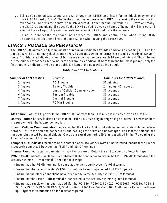
LINKS TROUBLE SUPERVISIONThe LINKS1000 automatically monitors its operation and indicates trouble conditions by flashing LED1 on thecircuit board. LED1 normally flashes once every 10 seconds when the LINKS is in stand-by (ready to transmit)mode. Troubles are indicated when LED1 flashes more than once at each 10 second interval. Shown beloware the number of flashes used to indicate each trouble condition. If more than one trouble is present, only thefirst trouble is indicated. When that trouble is cleared, the next will be indicated.
Table 2 — LED1 Indications
Number of LED Flashes Trouble Time-outs for LINKS failures2 flashes AC Trouble 30 minutes3 flashes Battery Trouble 2 minutes, 40 seconds4 flashes Loss of Cellular Communication 30 seconds6 flashes Tamper Trouble 30 seconds7 flashes Internal Trouble 30 seconds8 flashes PGMIn Trouble 30 seconds
AC Failure: Loss of AC power to the LINKS1000 for more than 30 minutes is indicated by an AC failure.
Battery Fault: A battery fault indicates that the LINKS1000 stand-by battery voltage is below 11.5 volts or thereis a problem with the battery connection.
Loss of Cellular Communication: Indicates that the LINKS1000 is not able to communicate with the cellularnetwork. Ensure the antenna connections and cabling are secure and undamaged, and that the antenna hasnot been obstructed by metal objects. Check the signal strength LED’s as described in the “Relocating theAntenna” section of this manual.
Tamper Fault: Indicates that the tamper contact is open. If a tamper switch is not installed, ensure that a jumperis securely connected between the “TMP” and “GND” terminals.
Internal Fault: Indicates that an internal fault has occurred. Return the unit to your distributor for repairs.
PGMIn Fault: Indicates that there is a problem with the connection between the LINKS PGMIn terminal and thesecurity system’s PGM terminal. Check the following:
•Ensure that the PGMIn terminal is connected to the security system’s PGM terminal
•Ensure that the security system’s PGM Output has been programmed for LINKS operation
•Ensure that no other connections have been made to the security system’s PGM terminal
•Ensure that the LINKS GND terminal is connected to the security system’s ground terminal
•Ensure that a resistor has been added (for the PC1550, PC4010, PC4020, PC4020KT, PC5010, PC5015,PC1555, PC1565, PC5008, PC580, PC585, P16LC, P1664 and Sur-Gard DC1664LC only). Refer to the Hook-up Diagram for information on the resistor required

When using End-of-Line Resistor Loops, connect the LINKS Trouble terminal(s) to unused zone(s) on thecontrol panel, and program the zone as a 24-hour Silent Zone (when using the PC4010, PC4020, PC4020KTor PC5010/PC5015/PC1555/PC1565/PC5008/PC580/PC585, program the zone as “LINKS Supervisory”). TheAlarm and Restoral Reporting Codes for that zone will be used to report a general trouble (which could be anyof the trouble conditions described above) on the LINKS1000.
Note that the PC4010, PC4020 and PC4020KT use the Zone Trouble and Zone Trouble RestoralReporting Codes to report a general LINKS trouble condition.
Reading trouble conditions on the LINKS1000 via the LINKS1000 ProgrammerNOTE: Any LINKS1000 software v2.x (starting at v2.1) will support a single event trouble buffer. LINKS1000software v3.0 and higher has a trouble buffer that will show the last four troubles that the LINKS1000registered.
The LINKS1000 Programmer v1.4 and later can be used to read the trouble, whether it is existing or cleared,provided the trouble was present long enough to set the supervisory trouble terminal(s) (SYS TBL, AC TBL andBat TBL).
Step 1. With AC power applied to the LINKS1000, connect the modular cord on the LINKS1000Programmer to the modular jack on the LINKS1000.
Step 2. Press any key on the Programmer to activate it.Step 3. Select the Trouble menu item.Step 4. The trouble items will be displayed.NOTENOTENOTENOTENOTE: For v2.x (2.1 and up) only the most recent trouble will be displayed. For v3.0 and higher, the most
recent event will be displayed when entereing the trouble menu, and then by using the arrow keys,the other three most recent troubles can be viewed.
Step 5. The trouble buffer can be reset by pressing the [F] key and holding for 2 seconds. This will setthe display to show “No Trouble”. It is not necessary to reset the trouble buffer to receive newevents.
Step 6. Press [#] to exit the Trouble menu.Step 7. If no programming is to be performed, shut off the LINKS1000 Programmer and disconnect it from
the LINKS1000. (See “Disconnecting the LINKS1000 Programmer.)
NOTE: Do not leave the LINKS1000 Programmer connected to the LINKS1000, as the LINKS1000 willnot function.
Table 3 — Messages Appearing on Programmer Trouble Screen
Message LINKS Trouble
“No Trouble” No problems in LINKS trouble memory“AC Trouble” AC failure“Battery Trouble” Battery trouble“Cellular Tbl” Loss of Cellular Signal“IIC Trouble” Self-Test-Internal Failure“Tamper Tbl” Tamper fault on LINKS“PGMIn Trouble” Trouble with PGMIn connection, control panel has not been programmed for
LINKS, or trouble with the ground connection between panel & LINKS1000.“LINKS Version Not Compatible” LINKS1000 is of an older version which does not have trouble memory.
28
NOTICE: The Industry Canada label identifies certified equipment. This certification means that the equipment meetscertain telecommunications network protective, operational and safety requirements. Industry Canada does notguarantee the equipment will operate to the user’s satisfaction.
Before installing this equipment, users should ensure that it is permissible to be connected to the facilities of the localtelecommunications company. The equipment must also be installed using an acceptable method of connection. Thecustomer should be aware that compliance with the above conditions may not prevent degradation of service in somesituations.Repairs to certified equipment should be made by an authorized Canadian maintenance facility designated by thesupplier. Any repairs or alterations made by the user to this equipment, or equipment malfunctions, may give thetelecommunications company cause to request the user to disconnect the equipment.
User should ensure for their own protection that the electrical ground connections of the power utility, telephone linesand internal metallic water pipe system, if present, are connected together. This precaution may be particularly importantin rural areas.
CAUTION: Users should not attempt to make such connections themselves, but should contact the appropriate electricinspection authority, or electrician, as appropriate.NOTICE: The Ringer Equivalence Number (REN) assigned to each terminal device provides an indication of themaximum number of terminals allowed to be connected to a telephone interface. The termination on an interface mayconsist of any combination of devices subject only to the requirement that the sum of the Ringer Equivalence Numberof all the devices does not exceed 5.The REN of this unit is 0.0B.
AVIS: L’étiquette de l’Industrie Canada identifie le matériel homologué. Cette étiquette certifie que le matériel estconforme à certaines normes de protection, d’exploitation et de sécurité des réseaux de télécommunications. IndustrieCanada n’assure toutefois pas que le matériel fonctionnera à la satisfaction de l’utilisateur.
Avant d’installer ce matériel, l’utilisateur doit s’assurer qu’il est permis de le raccorder aux installations de l’entrepriselocale de télécommunication. Le matériel doit également être installé en suivant une méthode acceptée de raccordement.L’abonné ne doit pas oublier qu’il est possible que la conformité aux conditions énoncées ci-dessus n’empêchent pasla dégradation du service dans certaines situations.Les réparations de matériel homologué doivent être effectuées par un centre d’entretien canadien autorisé désigné parle fournisseur. La compagnie de télécommunications peut demander à l’utilisateur de débrancher un appareil à la suitede réparations ou de modifications effectuées par l’utilisateur ou à cause de mauvais fonctionnement.
Pour sa propre protection, l’utilisateur doit s’assurer que tous les fils de mise à la terre de la source d’énergie électrique,les lignes téléphoniques et les canalisations d’eau métalliques, s’il y en a, sont raccordés ensemble. Cette précaution estparticulièrement importante dans les régions rurales.
AVERTISSEMENT: L’utilisateur ne doit pas tenter de faire ces raccordements lui-même; il doit avoir recours à unservice d’inspection des installations électriques, ou à un électricien, selon le cas.AVIS: L’indice d’équivalence de la sonnerie (IES) assigné à chaque dispositif terminal indique le nombre maximal determinaux qui peuvent être raccordés à une interface. La terminaison d’une interface téléphonique peut consister en unecombinaison de quelques dispositifs, à la seule condition que la somme d’indices d’équivalence de la sonnerie de tousles dispositifs n’excède pas 5.
L’indice d’équivalence de la sonnerie (IES) de ce produit est 0.0B.

29002430 R3
Digital Security Controls Ltd. warrants that for a period of twelve months from the date of purchase, the productshall be free from defects in materials and workmanship under normal use and that in fulfilment of any breechof such warranty, Digital Security Controls Ltd. shall, at its option, repair or replace the defective equipmentupon return of the equipment to its repair depot. This warranty applies only to defects in parts and workmanshipand not to damage incurred in shipping or handling, or damage due to causes beyond the control of DigitalSecurity Controls Ltd., such as lightning, excessive voltage, mechanical shock, water damage, or damagearising out of abuse, alteration or improper application of the equipment.
The foregoing warranty shall apply only to the original buyer, and is and shall be in lieu of any and all otherwarranties, whether expressed or implied and of all other obligations or liabilities on the part of Digital SecurityControls Ltd. Digital Security Controls Ltd. neither assumes, nor authorizes any other person purporting to acton its behalf to modify or to change this warranty, nor to assume for it any other warranty or liability concerningthis product.
In no event shall Digital Security Controls Ltd. be liable for any direct or indirect or consequential damages,loss of anticipated profits, loss of time or any other losses incurred by the buyer in connection with thepurchase, installation or operation or failure of this product.
WARNING: Digital Security Controls Ltd. recommends that the entire system be completely tested on a regularbasis. However, despite frequent testing, and due to but not limited to, criminal tampering or electricaldisruption, it is possible for this product to fail to perform as expected.
LIMITED WARRANTY
How to Contact Us:SalesFor information about additional products, please call our sales number: 1-800-418-7618, ore-mail us at [email protected].
Technical SupportIf you have questions of problems when using Sur-Gard products, you can call our TechnicalSupport Department, or e-mail us at [email protected]. If you are within the United States,Puerto Rico, the U.S. Virgin Islands or Canada, you can get support by dialing 1-800-503-5869. Ifyou are outside these areas, please call (416) 665-4494.
InternetSur-Gard is now on the World Wide Web. You will be able to search the Sur-Gard technicalinformation database and read information about new products at our web site. You will also be ableto send us your questions. Our World Wide Web address is http://www.sur-gard.com.
© 1999 Sur-Gard Security Systems Ltd.401 Magnetic Drive, Unit #24Downsview, Ontario, Canada M3J 3H9