Embed Size (px)
Citation preview

LINUX DEVICE DRIVER SYNTHESIS AND VERIFICATION
By
Yi Li
Thesis
Submitted to the Faculty of the
Graduate School of Vanderbilt University
in partial fulfillment of the requirements
for the degree of
MASTER OF SCIENCE
in
Computer Science
December, 2015
Nashville, Tennessee
Approved:
Theodore Bapty, Ph.D
Sandeep Neema, Ph.D

TABLE OF CONTENTS
Page
LIST OF FIGURES . . . . . . . . . . . . . . . . . . . . . . . . . . . . . . . . . . iv
I Introduction . . . . . . . . . . . . . . . . . . . . . . . . . . . . . . . . . . . 1
I.1 Problem . . . . . . . . . . . . . . . . . . . . . . . . . . . . . . . . . . . 1I.2 Solution Summary . . . . . . . . . . . . . . . . . . . . . . . . . . . . . . 3
II Background . . . . . . . . . . . . . . . . . . . . . . . . . . . . . . . . . . . 5
II.1 Generic Modeling Environment . . . . . . . . . . . . . . . . . . . . . . . 5II.2 Zing . . . . . . . . . . . . . . . . . . . . . . . . . . . . . . . . . . . . . 5II.3 P Language . . . . . . . . . . . . . . . . . . . . . . . . . . . . . . . . . . 5
II.3.1 Ghost Machine . . . . . . . . . . . . . . . . . . . . . . . . . . . . 6II.3.2 Asynchronous Semantic . . . . . . . . . . . . . . . . . . . . . . . 7II.3.3 External Functions . . . . . . . . . . . . . . . . . . . . . . . . . . 8
III Implementation . . . . . . . . . . . . . . . . . . . . . . . . . . . . . . . . . 9
III.1 Overview of the Solution Architecture . . . . . . . . . . . . . . . . . . . 9III.2 Driver Modeling Domain Specific Language . . . . . . . . . . . . . . . . 10III.3 Domain Meta-model . . . . . . . . . . . . . . . . . . . . . . . . . . . . . 12
III.3.1 Top Level: View . . . . . . . . . . . . . . . . . . . . . . . . . . . 12III.3.2 Second Level: AbsScope . . . . . . . . . . . . . . . . . . . . . . 13III.3.3 Third Level: StateMachine . . . . . . . . . . . . . . . . . . . . . 17
III.4 Code Generator . . . . . . . . . . . . . . . . . . . . . . . . . . . . . . . 19III.4.1 The Entry Point . . . . . . . . . . . . . . . . . . . . . . . . . . . 20III.4.2 The Generated P Program . . . . . . . . . . . . . . . . . . . . . . 22III.4.3 File Operation and External Function . . . . . . . . . . . . . . . . 23
III.5 The verifier . . . . . . . . . . . . . . . . . . . . . . . . . . . . . . . . . . 31III.5.1 State Level Responsiveness . . . . . . . . . . . . . . . . . . . . . 32III.5.2 Machine Level Responsiveness . . . . . . . . . . . . . . . . . . . 33
IV Case Study . . . . . . . . . . . . . . . . . . . . . . . . . . . . . . . . . . . . 35
IV.1 The Driver Model . . . . . . . . . . . . . . . . . . . . . . . . . . . . . . 35IV.2 Execution . . . . . . . . . . . . . . . . . . . . . . . . . . . . . . . . . . 39IV.3 Concurrency . . . . . . . . . . . . . . . . . . . . . . . . . . . . . . . . . 40
ii
Chapter

V Future Work . . . . . . . . . . . . . . . . . . . . . . . . . . . . . . . . . . . 42
V.1 Device Class Specification . . . . . . . . . . . . . . . . . . . . . . . . . . 42V.2 Hardware Software Co-design . . . . . . . . . . . . . . . . . . . . . . . . 43
VI Conclusion . . . . . . . . . . . . . . . . . . . . . . . . . . . . . . . . . . . . 44
BIBLIOGRAPHY . . . . . . . . . . . . . . . . . . . . . . . . . . . . . . . . . . 45
iii

LIST OF FIGURES
Figure Page
II.1 P State Machine . . . . . . . . . . . . . . . . . . . . . . . . . . . . . . 6
II.2 Ghost Machine . . . . . . . . . . . . . . . . . . . . . . . . . . . . . . . 7
II.3 Asynchronous Semantic . . . . . . . . . . . . . . . . . . . . . . . . . . 8
III.1 Overview of the Solution Architecture . . . . . . . . . . . . . . . . . . . 9
III.2 Driver Structure . . . . . . . . . . . . . . . . . . . . . . . . . . . . . . 11
III.3 View . . . . . . . . . . . . . . . . . . . . . . . . . . . . . . . . . . . . 13
III.4 AbsScope is inherited by UserScope, DriverScope, and Environment . . 14
III.5 View in a Driver Model . . . . . . . . . . . . . . . . . . . . . . . . . . 14
III.6 AbsScope . . . . . . . . . . . . . . . . . . . . . . . . . . . . . . . . . . 15
III.7 AbsScope in a Driver Model . . . . . . . . . . . . . . . . . . . . . . . . 15
III.8 AbsFunc . . . . . . . . . . . . . . . . . . . . . . . . . . . . . . . . . . 16
III.9 StateMachine . . . . . . . . . . . . . . . . . . . . . . . . . . . . . . . . 17
III.10 StateMachine in a Driver Model . . . . . . . . . . . . . . . . . . . . . . 18
III.11 The Structure of Generated Code . . . . . . . . . . . . . . . . . . . . . 19
III.12 The Basic Situation . . . . . . . . . . . . . . . . . . . . . . . . . . . . 24
III.13 Event Passing Through a File Operator . . . . . . . . . . . . . . . . . . 25
III.14 Event Passing Through a External Function . . . . . . . . . . . . . . . . 30
IV.1 Top Level of Schar . . . . . . . . . . . . . . . . . . . . . . . . . . . . . 36
IV.2 Scope and State Machines . . . . . . . . . . . . . . . . . . . . . . . . . 37
iv

IV.3 User Machine . . . . . . . . . . . . . . . . . . . . . . . . . . . . . . . 37
IV.4 Driver Machine . . . . . . . . . . . . . . . . . . . . . . . . . . . . . . . 38
IV.5 Flowchart of Writing . . . . . . . . . . . . . . . . . . . . . . . . . . . . 40
IV.6 Zing Error Trace . . . . . . . . . . . . . . . . . . . . . . . . . . . . . . 41
v

CHAPTER I
Introduction
I.1 Problem
The device driver is a program which provides a software interface to a hardware device
enabling operating systems and other computer programs to access hardware functions
without needing to know details of the hardware. It can be treated as an abstraction layer
between hardware devices and operating systems. Device drivers are usually contained in a
Monolithic-kernel operating system, which is one of most important part in system kernel.
[1] shows that the driver code accounts for about 70% of the code size in Linux Kernel 2.4.
[2] mentions that 85% of Windows blue screens of death are caused by the driver codes of
Windows kernel. Nowadays, drivers have become a key factor in defining the reliability of
the system and a primary source of catastrophic bugs.
However, recent aggressive scaling of complex hardware and software components [3] is
making device drivers increasingly complex and cumbersome. For example, the length of
source code of the USB hub driver in Linux kernel is over 5500 lines and we find there were
several bugs that have stayed in the kernel bug list for over 3 years. A USB hub is shared
by multiple USB devices. Therefore the conflict of these devices with different versions
of USB ports and decrease in performance caused by inappropriate concurrent strategy are
usually the problems. These problems are hard to detect and fix manually. Thus, to adapt
the trend in the growing scale of device drivers, finding a new reliable methodology for the
driver development process becomes an urgent task.
In general, there are two main problems in the traditional device driver development pro-
cess: the ambiguity of documents and the unsatisfactory testing techniques.
1

1) Ambiguity of documents.
In manual development process, developers of device drivers need to pay attention to not
only the device and user programs but also the operating system interface. Both sides rely
on informal documentation such as the device interface description from the vendor, corre-
sponding system API in the driver developer’s manual, and comments in the kernel source
code, which makes the development process tedious and error prone. For example, there
may be several versions of system API documents written independently by different au-
thors or missing information about the newest device version. These kinds of mistakes are
more likely to occur with the growing scale and rapid turn around time of hardware devel-
opment.
2) Unsatisfactory testing techniques.
In most operating systems, drivers are a kind of special program which runs directly on the
OS kernel level. Thus, traditional testing techniques may not help in detecting errors in
the driver code. Since the OS kernel is a highly concurrent environment, it is difficult to
determine the exact operation or time when there is a fault in the interaction between the
driver and the kernel. Suppose we use the Unit Test technique in the driver development
process. Due to the indeterminacy of the OS kernel, the unit-test case could go into some
inconsistent state and the crash is reported after a long time, blurring the real cause of the
crash. Moreover, some bugs of drivers that may hide well in normal circumstances can
appear in rare and exceptional cases. In this situation, we cannot find a unit-test case to
cover these kinds of driver errors.
In order to solve these problems, we posit that a model-driven automatic synthesis is a
good choice. Programmers can simply create the device driver by designing its model on
their computer, which can be converted to a series of formal specifications of the driver
and its environment. Then, the synthesis tool-chain can generate the resulting driver au-
2

tomatically. By using driver synthesis, programmers can avoid wasteful effort. Moreover,
since driver synthesis uses formal specifications rather than documents written in natural
language, computers can now understand the detailed information of the internal strategy
of device drivers, which enable computer to find those potential driver errors with the tech-
nology called formal verification.
This thesis details such a device driver synthesis and verification tool chain under the Linux
operating system. We make the following contributions. First, we present an approach
for automatically synthesizing driver code based on Model Integrated Computing (MIC)
concepts. Second, we define a formal graph based Domain Specific Modeling Language
(DSML) for specifying a device driver model and its environment. Third, we use model
checking techniques for verifying that the resulting device driver constitutes a faithful de-
vice behavior while eliminating errors introduced during manual abstractions.
I.2 Solution Summary
Formalizing device description from environment related details is the key to our approach.
Thus, the user-defined driver model is the input and the output is the resulting driver. The
input model includes the software behavior of the hardware device and the I/O interface
between user programs, low level device control and the driver, which is defined formally
by the programmer with our DSML. Finally, this information will be converted into the
implementation of the driver by the code generator.
By defining a driver model, a developer can reuse duplicated driver code, simplify the de-
velopment process and describe the details of the driver behavior more precisely at a higher
level without concrete low-level code. In contrast to automatic driver synthesis, manual de-
velopment relies on informal documentation such as the device interface description from
the vendor, corresponding system API in the driver developer’s manual, and comments in
3

the kernel source code. This traditional manual approach is tedious and error prone. Our
automatic approach thus is more reliable and less ambiguous compared to the manual ap-
proach.
Moreover, inspired by research in program synthesis [4], we have integrated formal verifica-
tion into our system and have chosen the model checking verifier as an abstract interpreter
in our tool chain. Thus, our tool-chain contains a verifier to check the correctness of the
resulting driver with the model-checking technology. However, it is usually difficult to ap-
ply model checking on a program fragment that contains concurrency and side effect (like
I/O statement) because the natural notion of equivalence in those programs is typically not
strict equality either in the most straightforward mathematical semantics or in the underly-
ing machine model. In the driver model, a driver is divided into its core, the environment,
and the I/O control flow between the two. The core of the driver and each component of
the environment are represented by several event driven state machines, which is a formal
system and easy to apply model-checking to verify the correctness. To keep the consistency
of the result of verification and the state machine at run-time, we used P language, devel-
oped by Microsoft Software Research (MSR), as an intermediate representation. Details of
P language are discussed in section 3. By using the P compiler, this part of the code not
only generates the core state machine wrapped by a glue layer in the implementation of the
driver, but also sends the corresponding verification code to the verifier.
The rest of the thesis is structured as follows. Section 2 gives background information about
MIC and DSML. Section 3 describes the details of our tool implementation including the
definition of the meta model, the concept of asynchronous finite state machines, and the
code generator. Section 4 shows an example that illustrates how our tool chain generates a
complete device driver.
4

CHAPTER II
Background
II.1 Generic Modeling Environment
The Generic Modeling Enveronment (GME) is a modeling tool that is highly customizable
for creating a graph based Domain Specific Modeling Language (DSML) and supports
metamodel modeling and program synthesis. It applies UML class diagrams for describ-
ing a DSML and implements a meta language to define the concepts, relationships, and
constraints of specific domains. A user is allowed to easily integrate code generators to
a domain model with its interpreter mechanism in GME. In this paper, the device driver
model is described by a DSML in GME. [6]
II.2 Zing
Zing is a flexible and scalable infrastructure for exploring states of concurrent software
systems developed by Microsoft Research. It uses an efficient SMT Solver called z3, which
has been applied in various software verification and analysis applications. Zing is currently
being used for developing drivers on Windows operating system and Windows Phone. In
our tool chain, Zing is one of the back-ends responsible for verifying the code emitted by
P compiler. [5]
II.3 P Language
P programming language is a domain specific language developed by Microsoft Research[7]
for asynchronous event driven programming. P language allows the programmer to spec-
ify the system as a collection of interacting state machines that communicate with each
other using events. A P program can be compiled into both executable code and the cor-
responding Zing code for verification purposes. In this paper, P is used as an intermediate
representation of the driver model state machine and finally generates the implementation
5

code in C and verification code for Zing. Since P language plays a very important role in
our methodology we briefly introduce key concepts of P language. [7]
II.3.1 Ghost Machine
Figure II.1: P State Machine
Fig II.1 shows a simple P program. ”A P program is a collection of state machines, that
communicates with each other through events. An event can be sent from one machine
to another and raised within a machine. Each machine is composed of states, transitions,
variables and events.”
There is an important concept in the P language called Ghost Machine. In a P program,
users can explicitly indicate that a state machine is a Ghost Machine to be used only dur-
ing verification, and elided during compilation and actual execution. Such behavior of P
language compiler is shown in Fig II.2 and this feature is really useful for users to describe
the state machines with the specific environment. [7]
6

Figure II.2: Ghost Machine
II.3.2 Asynchronous Semantic
Compared to synchronous languages such as Esterel, Lustre and Signal, P is an asyn-
chronous languages with less restrictions on state machine definition. This means it is
unnecessary for a state machine to handle every incoming event at every clock tick. Fig
II.3 shows a typical example of using this feature. By using the keyword defer, a certain
state (the state Busy in fig II.3) in a state machine can defer a set of events and save these
unhandled events to the event queue. However, such deferred processing should be explic-
itly indicated by user and the failure to handle events is detected by automatic verification.
Moreover, to prevent user silencing the verifier by making every event deferred in every
state, the P verifier implements a liveness check that prevents deferring events indefinitely.
[7]
The reason why we chose the language with asynchronous semantics in our driver synthesis
methodology is that it is usually impractical for a driver state machine to handle every event
in every time node, which is required by synchronous semantics. This deferred processing
7

feature in P language makes the state machine representation more flexible.
Figure II.3: Asynchronous Semantic
II.3.3 External Functions
P language provides a strategy to integrate those user defined external functions into the
state machines. The external functions must have one additional argument on top of the
ones declared in P, which points to external memory that can be used by programmers
to persist some information as a part of the state of calling machine. The externals are
assumed to terminate and self manage its memory. In this thesis, all driver-specific low
level IO actions are represented by external functions.
8

CHAPTER III
Implementation
III.1 Overview of the Solution Architecture
Figure III.1: Overview of the Solution Architecture
Fig.III.1 gives an overview of the solution architecture. First, a device driver model, as
an input, can be defined inside GME with the graph based domain specific language. Ac-
cording to the semantic of DSL, these state machines that describe the core logic of the
driver and simulate the behaviors coming from user and device components can be decou-
pled from the input model and be interpreted into the intermediate representation, the P
code. From the state machine representation, the P compiler generates the corresponding
C source code forming the logic part of the device driver. Moreover, the corresponding
9

zing code is also generated in this process for verification purposes. These information
about the file control function and user-defined external function will be extracted from the
original model to generate the I/O interface, the glue layer which adapts the state machine
to the kernel space. Finally, these state machine code, I/O interface, and external function
defined by the user constitute the whole driver implementation while the zing code is sent
to the verifier.
It is a noteworthy fact that the state machines in user design models consist of the driver
machine and its environment. The two parts will be represented by the corresponding P
code. However, the environment is composed of something called ”Ghost Machines” in P
language which are used only during verification and are erased during actual execution.
III.2 Driver Modeling Domain Specific Language
Our driver modeling domain specific language is defined by a GME domain meta model.
In this section, before we examine the detail of the domain meta model, we will give a gen-
eral idea about how our language describes a device driver model, illustrated by Fig III.2.
A typical device driver plays the role of connecting user programs to the device. Thus,
naturally, the driver model can be divided into three parts: user space, driver space, and
device space.
1) User space contains these state machines that simulate the actions of user programs.
2) Driver space is the entity of the device driver that responds to requests from the user
programs and communicates with the hardware.
3) Device space is a virtual component of the driver model which mimics the behavior of a
physical device.
10

Figure III.2: Driver Structure
Between user space and driver space, there is a collection of I/O control function which
forward those device accessing requests from user programs to the device driver. Specif-
ically, since the UNIX paradigm for a device is to treat each one as a file, this interface
layer consists of several file operation (like open, read ,write, and close). Similarly, the
layer between driver space and device space is also an interface providing a serious exter-
nal function for the driver to communicate with the physical device.
Moreover, to formalize those behaviors of user, driver and device, in our domain specific
language, the whole system (these three parts) is treated as a collection of interacting state
machines, which communicate with each other using events. At the state machine level,
for verification purposes, those request from user programs are the events generated by the
11

user machine as the inputs to the driver machine, while those device control commands are
the events generated by the driver machine as the inputs to the device machine.
At the runtime level, both user space and device are erased in a concrete driver source code.
Thus, to generate the implementation of a device driver from a driver model, in our domain
specific language, each file operation mentioned before is bound with an input event of the
driver state machine while each output event is related to an external function. Thus, in
the implemented driver source code at execution time, after calling a file operation from
a user program, the corresponding events will be launched and fire the transition in the
driver state machine. Similarly, that a driver machine sends an event to the device machine
at state machine level means the corresponding hardware control function (user defined
external function) will be called at execution time.
III.3 Domain Meta-model
In this section, we illustrate the syntax elements in our driver modeling language which are
defined by a GME meta model. In general, our driver modeling language has a hierarchical
structure with three different levels, which are View, Scope ,and StateMachine. Each level
is defined by the GME meta model language.
III.3.1 Top Level: View
The meta model of model View is presented in Fig III.3 and Fig III.4, from which pro-
grammer can overview the whole driver model. There is only three elements in View:
AbsScope, AbsFunc, and FuncToFunc.
1) AbsScope is an abstract model belonging to the model View. UserScope,DriverScope
,and Environment, are drived from AbsScope. The top level of driver modeling language
can contain several AbsScopes. Recalling that the world is split into three pieces, user
space, driver space and device space, this scheme is quiet self-explanatory. UserScope is
12

related to the user space and DriverScope represents the driver space while Environment
means the device space. Typically, a driver model contain one or multiple UserScopes, one
DriverScope and multiple Environments.
2) AbsFunc is a model and the port of AbsScope, which is intruduced in the next subsec-
tion (model AbsScope).
3) FuncToFunc is a connection that connects one AbsFunc to another. AbsFuncs of
an AbsScope and the corresponding connections FuncToFunc constitute the interface be-
tween one AbsScope and another, for example, those file operations between the user space
and the driver space.
Figure III.3: View
III.3.2 Second Level: AbsScope
The model AbsScope is the second level of our driver modeling language, included by
View. It is presented in Fig III.6, which contains the following entries:
1) The model StateMachine represents the collection of state machines of a driver model.
In this level, the StateMachine has two kinds of ports: InputEvent, which represents those
13

Figure III.4: AbsScope is inherited by UserScope, DriverScope, and Environment
Figure III.5: View in a Driver Model
incoming events from the outside of a state machine, while OutputEvent means the events
emitted by a state machine. The internal detail of the model StateMachine will be intro-
duced in next subsection (model StateMachine).
14

Figure III.6: AbsScope
Figure III.7: AbsScope in a Driver Model
2) The model AbsFunc is represented by Fig III.8, which represents the functional inter-
face between scope and scope. AbsFunc is an abstract model from which FileOperation
15

Figure III.8: AbsFunc
and extFunction are derived. Naturally, an AbsScope has multiple AbsFuncs. A User-
Scope can only have FileOperation and Environment can only has extFunction, while
both FileOperations and extFunctions can be contained by a DriverScope. Moreover, an
AbsFunc has a substructure called retVal as the port of the model which represents those
return values of a function (an AbsFunc may has multiple retVal as its ports). Finally,
FileOperation has 5 subtypes called Open, Close, Write, Read, and Ioctl that correspond
with those Linux basic file operation functions.
3) Those connections at scope level are driven by the events transitive relationship. For
each pair of state machines in the same scope, it is natural that there is a connection be-
tween an output event of one state machine and an input event of the other, represented
by the connection OutputAsIuput. The connection FuncRelateInput between a model
AbsFunc and a port InputEvent means that an input event is related to the corresponding
function. Similarly, there is a connection OutputRelateFunc. Moreover, the connection
16

RetValAsInput represent that one return value from a function can be an input event of a
state machine, while OutPutAsRetVal means we can treat an output event as a function
return value.
III.3.3 Third Level: StateMachine
Model StateMachine is the third level of our driver modeling language, included in AbsS-
cope. It is presented in Fig III.9, which contains the following entries:
Figure III.9: StateMachine
1) The model AbsState and Connector constitute the basic semantic of a finite state ma-
chine representation, which are states and the transitions between two different states. An
AbsState can connect another AbsState through a Connector with connection SrcState-
ToConnector and ConnectorToDstState. Connection ConnectorAssociateToEvent con-
necting an InputEvent to a Connector represents a transition between two states guarded
17

Figure III.10: StateMachine in a Driver Model
by an event. Then, there are two kinds of states: State, representing a regular state and
StartState, which is used to indicate the initial appearance of a state machine. Both of
them derived from AbsState. All of these elements are contained by the aspect Machine.
2) The aspect emitting includes model AbsState, model OutputEvent, and connection
StateEmitOutputEvent. It means the corresponding OutputEvent will be emitted by a
state machine when the machine enters into a specific state.
3) The aspect deferring includes model AbsState, model InputEvent and connection
StateDeferInputEvent. According to the definition of asynchronous semantic in P lan-
guage introduced at section 2.3, we can connect a InputEvent to a AbsState under the
deferring aspect, to indicate that a certain state defers a set of events and saves these un-
handled events to the event queue in GME.
18

Figure III.11: The Structure of Generated Code
III.4 Code Generator
Our methodology aims to help programmers to develop a usable device driver according
an input device driver model.
A complete device driver includes two parts of code, the user-defined external functions
and the code generated by our tool chain. In this section, we illustrate the internal strategy
used in our code generator.
A GME interpreter can extract the necessary information from a driver model, and the ex-
traction logic can be written in varying programming language (in this paper, we use C#
to write the interpreter). This process is automatic through generative capabilities. In our
salutation, the interpreter is responsible for generating the P source file for the state ma-
chine and C code (including source and header file) for the driver framework. In addition,
an automatic build script will be created after this procedure.
19

The structure of the generated code is presented in Fig III.11. From a input, a GME driver
model, our interpreter generates the following files:
driver.c: the main framework of the target device driver.
impl.c: the collection of the assistant functions of the P state machine.
driver.h: the collection of foreign function declarations.
driver.p: the P state machine program that can be compiled into the c source code by the P
compiler.
III.4.1 The Entry Point
We start at the driver entry point defined in driver.c. An example is presented by Listing
III.1. The logic of the entry function, dev init, is quite simple. The first step is to register
the device and obtain the device point, cdev. Then, the function allocates the memory space
for the device context, ctx, which is an area of shared data of the driver. Moreover, instead
of initializing a series of variables and logic in traditional driver initializing functions, we
simply start a P process, make a P state machine and add the machine point into the device
context. After this point, the ownership of the device driver is claimed by the P state ma-
chine. Any user action is treated as an event passing into the P state machine through a file
operation (recall that each device is represented by a system file in Linux).
Listing III.1: driver.c
s t a t i c i n t d e v i n i t ( vo id )
{
20

i n t r e s u l t ;
i n t i ;
/ * g e t d r i v e r number and r e g i s t e r * /
d e v t devno = MKDEV( dev major , 0 ) ;
. . .
/ * i n i t a c h e r d e v i c e * /
c d e v i n i t (&cdev , &d e v f o p s ) ;
cdev . owner = THIS MODULE ;
cdev . ops = &d e v f o p s ;
/ * a l l o c memory f o r d e v i c e c o n t e x t * /
cdev add (&cdev , MKDEV( dev major , 0 ) , MEMDEV NR DEVS ) ;
c t x = kma l loc (MEMDEV NR DEVS *
s i z e o f ( s t r u c t d e v c t x ) , GFP KERNEL ) ;
/ * l i n k d e v i c e p o i n t t o c o n t e x t * /
c tx−> dev = cdev ;
/ * c a l l a use r−d e f i n e d i n i t f u n c t i o n * /
d e v u s e r i n i t ( c t x ) ;
/ * c r e a t e s t a t e machine * /
c tx−>p r o c e s s = P r t S t a r t P r o c e s s ( p roces sGu id ,
&P GEND PROGRAM,
E r r o r H a n d l e r ,
Log ) ;
21

p a y l o a d = Pr tMkNul lValue ( ) ;
c tx−>mc = PrtMkMachine ( p r o c e s s ,
P MACHINE Driver , p a y l o a d ) ;
/ * l i n k d e v i c e c o n t e x t t o P machine c o n t e x t * /
mc−>e x t C o n t e x t = c t x ;
. . .
r e t u r n 0 ;
f a i l m a l l o c :
u n r e g i s t e r c h r d e v r e g i o n ( devno , 1 ) ;
}
m o d u l e i n i t ( d e v i n i t ) ;
III.4.2 The Generated P Program
A P program is a collection of state machine definitions. Since the semantic of model
StateMachine in our driver modeling language is one to one related to a state machine
definition in P language, it is not difficult to translate a state machine in our model to a P
state machine. However, there are two differences we need to point out here.
1) Because the view of the state machine is the top level view in P language, in our driver
modeling language, those state machines in different scopes are unfolded into a group of
plain state machines definitions. Recall we should explicitly indicate those state machines
which need be erased at runtime in a P program. Thus, those state machines in UserScope
and Environment are declared as virtual state machines in a P program(with key word
22

model).
2) P language does not support the feature that a state machine defines an unguarded transi-
tion between two states. Thus, for an unguarded transition in our driver modeling language,
when it is translated into a P program, the source state will self-raise an inner event called
eUnit and the original unguarded transition will be a transition guarded by the event eUnit.
III.4.3 File Operation and External Function
In this subsection we discuss the detailed implementation of the file operations and exter-
nal function interface in the generated driver code, which includes both P language code
and C source code. Instead of giving an analysis of the whole program, we plan to discuss
several typical situations to explain how events are transited at both state machine level and
runtime level.
1) There are two state machines in the same scope with one event emitted from one to the
other, presented by Fig III.12. This is the most simple situation. Since the active event does
not pass through two different scopes, there is no AbsFunc involved in this process and
there is no generated C source code for this situation. A P program segment is generated
directly according to the state machine semantic, presented by Listing III.2.
23

Listing III.2: basic situation
machine M1
{
s t a t e s o m e S t a t e 1
{
e n t r y { send M2, E1 ;}
}
. . .
}
machine M2
{
s t a t e s o m e S t a t e 1
{
. . .
on E1 go to s o m e S t a t e 2 ;
}
}
Figure III.12: The Basic Situation
24

2) There are two state machines: one is in a UserScope and the other in a DriverScope
with one event emitted from one to the other through a file operation. According to Fig
III.13, the file operation Read can have several return values and each return value has a
corresponding event emitted from M2 to M1. The P program segment is quite similar to
the basic case, presented by Listing III.3.
Figure III.13: Event Passing Through a File Operator
Listing III.3: event passing through a file operator
/ / u s e r scope machine
model M1
{
s t a t e s o m e S t a t e 1
{
e n t r y { send M2, eRead } ;
}
. . .
s t a t e h a n d l e R e t V a l
{
25

. . .
on eSucc go to s o m e S t a t e 2 ;
on e F a i l go to s o m e S t a t e 3 ;
}
}
/ / d r i v e r scope machine
machine M2
{
s t a t e s o m e S t a t e 1
{
. . .
on eRead go to s o m e S t a t e 2 ;
}
. . .
s t a t e r e t S u c c
{
e n t r y
{
M 2 r e t e S u c c ( ) ;
send M1, eSucc ;
}
}
s t a t e r e t F a i l
{
e n t r y
{
26

M 2 r e t e F a i l ( ) ;
send M1, e F a i l ;
}
}
}
There are two foreign functions, M2 ret eSucc and M2 ret eFail, and both of their C code
program segments are automatically generated by the code generator, presented by Listing
III.4. These functions are responsible for sending the return values to user space by chang-
ing the device context(recall that M1 is a virtual machine. Thus, those event eSucc and
eFail will disappear at runtime).
Listing III.4: function M2 ret eSucc
enum r e t { eSucc , e F a i l , . . . } ;
s t r u c t d e v c t x
{
. . .
i n t R e a d r e t f l a g = FALSE ;
enum r e t R e a d r e t v a l u e ;
}
s t a t i c vo id M 2 r e t e S u c c ( s t r u c t d e v c t x * c t x )
{
l o c k ( d e v l o c k ) ;
c tx−>R e a d r e t f l a g = TRUE;
R e a d r e t v a l u e = eSucc ;
un lo ck ( d e v l o c k ) ;
27
}
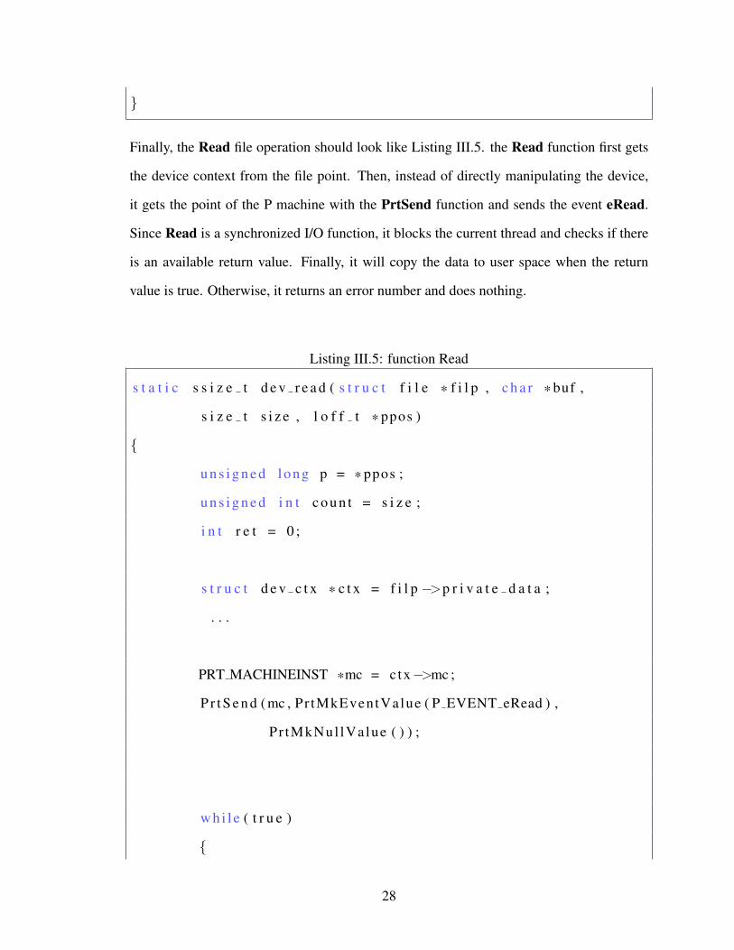
Finally, the Read file operation should look like Listing III.5. the Read function first gets
the device context from the file point. Then, instead of directly manipulating the device,
it gets the point of the P machine with the PrtSend function and sends the event eRead.
Since Read is a synchronized I/O function, it blocks the current thread and checks if there
is an available return value. Finally, it will copy the data to user space when the return
value is true. Otherwise, it returns an error number and does nothing.
Listing III.5: function Read
s t a t i c s s i z e t d e v r e a d ( s t r u c t f i l e * f i l p , c h a r * buf ,
s i z e t s i z e , l o f f t * ppos )
{
u n s i g n e d long p = * ppos ;
u n s i g n e d i n t c o u n t = s i z e ;
i n t r e t = 0 ;
s t r u c t d e v c t x * c t x = f i l p −>p r i v a t e d a t a ;
. . .
PRT MACHINEINST *mc = ctx−>mc ;
P r t S e n d ( mc , Pr tMkEventValue ( P EVENT eRead ) ,
Pr tMkNul lValue ( ) ) ;
w h i l e ( t r u e )
{
28

i f (TRUE == ctx−> R e a d r e t f l a g )
b r e a k ;
}
i f ( eSucc == c tx−>R e a d r e t v a l u e )
{
/ * copy t o u s e r * /
c o p y t o u s e r ( buf , ( vo id * ) ( dev−>d a t a + p ) , c o u n t )
. . .
r e t = 0 ;
}
e l s e
r e t = −EFAULT ;
r e t u r n r e t ;
}
3) There are two state machines: one is in a DriverScope and the other in an Environment
with one event emitted from one to the other through an external function, presented by Fig
. III.14.
This case is quite similar to the second case. However, since the external functions usually
are hardware specific functions which are responsible for directly communicating with the
device, the generated codes are just function warps and the implementation of those exter-
nal functions should be completed by the user. Since the machines at the Environment
scope are virtual, the function warp obtains the return value from the user defined function
and sends the corresponding event to the P machine at runtime. An external function warp
29

Figure III.14: Event Passing Through a External Function
looks like Listing III.6.
Listing III.6: external function warp
enum r e t { r e t 1 , r e t 2 , . . . } ;
r e t a c t i o n i m p ( d e v c t x * ) ; / * s h o u l d be d e f i n e d by u s e r * /
vo id a c t i o n ( d e v c t x * c t x )
{
PRT MACHINEINST *mc = ctx−>mc ;
enum r e t r e t v a l = a c t i o n i m p ( c t x ) ;
s w i t c h ( r e t v a l )
{
c a s e r e t 1 : P r t S e n d ( mc ,
Pr tMkEventValue ( P EVENT ret1 ) ,
Pr tMkNul lValue ( ) ) ;
b r e a k ;
30

c a s e r e t 2 :
. . .
}
}
III.5 The verifier
After the P program is generated by our code generator, as we mentioned before, the cor-
responding Zing code is generated by the P compiler for verification purpose. P language
contains constructs to build responsive programs. This section describe these three liveness
properties according the semantic of P language.
First, we formalize the state machine semantic of our driver modeling language.
• M is a sequence of state machines mi that contains all these state machines in a driver
model, where mi represents a state machine.
• E is a sequence of events e j that contains all events in the driver model, where e j
represents a state machine.
• For each state machine mi, its states consist of a set mi.S = {mi.s1,mi.s2..,mi,sn},
where sk represents a specific state. The start state is mi.sstart
• For each state machine mi, its transitions consist of a set mi.T = {(src,dst,ei)...},
where src,dst ∈ mi.S and ei ∈ E.
• For each state mi.s j in a certain state machine mi, its deferrable events consist of a
set mi.s j.D = ea, ...,eb, where ei ∈ E.
31

• For each state mi.s j in a certain state machine mi, its output events consist of an
sequence mi.s j.Out = (ea, ...,eb), where ei ∈ E.
III.5.1 State Level Responsiveness
First, we need to construct a single state machine m′ that is equivalent to our former defini-
tion.
• The set of states of machine m′ is m′.S, which is the Cartesian product of mi.S, where
m1×m2...×mn = {m1.sa,m2.sb, ...,mn.sc}. Since M is a sequence, we can sim-
plify the denotation to (sa,sb, ...,sc), where the i-th sk means mi.sk. The start state is
(sstart , ...,sstart)
• For all transitions (src,dst,ei)∈mi.T , there is a corresponding transition (src′,dst ′,ei,Out)∈
m′.T , where src′ = (..., src︸︷︷︸i-th
, ...), dst ′ = (..., dst︸︷︷︸i-th
, ...) , ei = ei and Out = dst.Out.
• For each state m′.st = (st1,st2, ...,stn), m′.st .D =⋃
i st i.D.
Thus, the operational semantics of state transitions in machine m′ has two situations:
m′.s1 ea ∈ eventQueue (m′.s1,m′.s2,ea,Out)m′.s2 eventQueue−{ea} eventQueue→ eventQueue∪Out)
andm′.s1 ea ∈ eventQueue ea ∈ m′.s1.D
m′.s1 eventQueue
.
The formulas mean for each event ea in the event queue, for current state m′.s1, there is
either a transition (m′.s1,m′.s2,ea,Out) or the deferrable events set m′.s1.D including ea.
Otherwise, an error will be detected. In the driver model level, since all those input events
32

come from the User scope, this property guarantees that there is no undefined behavior for
any valid user operation.
III.5.2 Machine Level Responsiveness
Two properties presented by [7] are about machine level responsiveness. In this section,
we give a brief summary and show the meaning of these two properties for a driver model.
• seched(m) holds iff a machine m takes a transition.
• enq(m,e,m′) hold iff a machine m enqueues an event e into machine m′.
• deq(m′,e) holds iff machine m′ dequeues an event e.
In the first property, the set of erroneous executions is given by
∃m.FG(sched(m)).
This equation specifies that a machine cannot execute indefinitely without becoming dis-
abled. In particular, a state machine should not get into a loop of operation without the
interaction with the other machines. In the driver model level, since a driver is an interface
between user and hardware, a driver machine with such deadlock represents that the driver
may have frozen the kernel in some situations, while a state machine in user or environment
scope means a bad design of the user/device behavior simulation (a remarkable fact is, in
this case, the driver machine may be right and the generated code can be executed correctly.
However, such an error will be detected by the verifier).
In the second property, the set of erroneous executions is given by,
∃m,e,m′.G(enq(m,e,m′)∨F¬deq(m′,e))∨FG¬ppn(m′,e)
33

where ppn(m,e) that holds whenever m is in a state whose list of postponed events contain
e.
The erroneous execution is one in which every machine is fairly scheduled and an event
is inserted into the event queue and never subsequently dequeued, which means that an
event equeued by a machine will eventually be dequeued. In the source code level, such
invalid events permanently stay in the event queue and eventually cause the event queue
overflow.[7]
34

CHAPTER IV
Case Study
In this section, we illustrate a simple char device driver called schar as a study case that is
generated by our driver synthesis tool-chain. Schar is a char driver that acts on a memory
area as though it were a device. The advantage is this device is hardware independent and
the substantial device is a memory allocated by the kernel. Thus, schar is portable across
the computer architectures on which Linux runs and clear enough to show how a complete
device driver is generated from an input model.
In general, schar is a disk device with read and write operations. It has two components,
a disk and a cache. When user programs write the data into schar, it will directly save the
data into the disk. When user programs read the data from schar, it will first try to find
the requested data in its cache. Limited by size, the cache may return incomplete data and
the driver is responsible for reading the rest of the data from the disk component. After the
data on the disk is accessed, the driver updates the cache.
To demonstrate how our approach improves the quality of driver codes and finds potential
bugs in the development process, we present two versions of the design of schar. The
first one is designed without the consideration of concurrency. We show that the flaw in
the driver can be detected by our driver synthesis tool-chain, Then, we present the revised
version.
IV.1 The Driver Model
The top level of the driver model of schar is presented by Fig IV.1, with one UserScope ,
one DriverScope and one Environment. Between UserScope and DriverScope, there are
four FileOperations: Open, Close, Read and Write. Similarly, the four extFunction are
35

Figure IV.1: Top Level of Schar
between DriverScope and Environment. They are:
1. fDisk Writing : writing the data to the Disk component.
2. fCache Reading : Reading the data from the Cache component.
3. fDisk Reading : Reading the data from the Disk component.
4. fDisk ReadingRestData : When the incomplete data is read from cache, reading
the rest of the data from the Disk component.
5. fCache Updating : When Disk is accessed, updating the Cache component.
According to Fig IV.2, UserScope has a state machine User, and Driver includes Driver,
while Environment contains two state machines, Disk and Cache, the components of
schar.
The User machine is presented by Fig IV.3. It is just a loop of these four file operations.
We first consider the situation with one User machine. Then, we will show the problem in
36
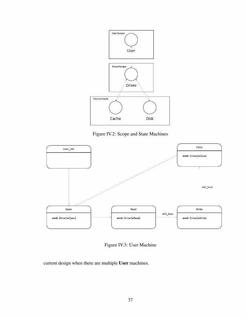
Figure IV.2: Scope and State Machines
Figure IV.3: User Machine
current design when there are multiple User machines.
37

Figure IV.4: Driver Machine
The Driver machine is presented by Fig IV.4. The initial state is Init. As soon as schar is
loaded into the Linux kernel, it will initialize itself, go to the state Idle and wait for events
in the input buffer. When a user program opens schar, the event eOpen will be sent to the
Driver machine and fire the Ready state. From Ready, there are two branches, the reading
process and the writing process. As we mentioned before, in the reading process, schar
first searches the requested data in Cache. If the data in Cache is incomplete, schar will go
to Disk Reading or Disk ReadingRest state and read the requested data from Disk. After
any disk operations, schar goes to Cache Updating and updates Cache. Finally, schar
goes to IO Succ state and returns success to the user program.
Since the device components Disk and Cache can only take one action at the same time, to
prevent user programs from repeatly reading and writing, all states in the Driver machine
38

except Init, Idle, and Ready have the deferrable event set containing the events eRead and
eWrite. This strategy works without problems under the single thread environment and we
will examine the concurrent situation later.
IV.2 Execution
The code of schar is generated from the previous driver model without any error message
reported from the verifier. The complete device driver contains the following user-defined
codes.
• The device probing function is empty here, since we assume the device is ready once
the driver is loaded into the kernel.
• The private data area of context contains the read/write buffer and two link lists
(Cache and Disk) located in computer memory.
• The allocating function creates an instance of the P machine and allocates memory
for the driver context.
• External functions correspond to those output events of the schar state machine,
which adds or removes the data by manipulating the link lists.
To demonstrate the execution of the driver, we use the writing process as an example. Fig
IV.5 presents the operations sequence of writing. The initialization process happens when
schar is loaded into the Linux kernel. In this process, the driver allocates the memory
for the driver context, registers these file operations and creates an instance of the driver
state machine. Then, suppose an user program calls the write function with the device ID
of schar. The driver first copies the input data from the user space to the kernel space
and saves it into the write buffer. Then, the driver gets the point of the driver state ma-
chine and sends the event eWrite. After this point, instead of directly manipulating the
hardware components(these link lists in memory space) the driver transfers its ownership
39

Figure IV.5: Flowchart of Writing
to the instance of driver state machine and waits for the return value. As we mentioned
before, the driver machine goes to states Disk Writing and Cache Updating and calls the
corresponding external functions to execute the writing action.
IV.3 Concurrency
The resulting driver seems to work well in the non-concurrent situation. In this section, we
illustrate how our synthesis tool chain reveals the potential bugs in schar when the driver
works in multiple task circumstances.
To simulate the concurrent environment, we simply add another instance of the User state
machine in our driver model. Thus, in the driver model, there are two user machines, the
driver machine ,and two components (Disk and Cache). After creating the driver model
40

and running our synthesis tool chain, the verifier found a wrong execution sequence in the
state machines system.
Figure IV.6: Zing Error Trace
This is how the problem occurred: when the driver machine accepted the event eOpen sent
by the first user machine and went to the state Ready, another eOpen sent by the second
user machine was an unhandled event for the driver machine. The reason is the program-
mer focus on only the property of the hardware device and misplaced eWrite and eRead
into the event deferred set of the state Ready (because Disk and Cache cannot be read or
written by two different instances simultaneously). This problem makes the event eOpen
become an undefined behavior when the device driver runs under a concurrency environ-
ment, which may cause a fatal system crash. For example, a user program can close a
device while another program is reading data from the device.
To fix this problem, the easiest way is, to add the events eOpen and eClose into the de-
ferrable events set of all states in the machine Driver except the states Init and Idle. This
solution can ensure that there is only one instance of a user program can accessing the
device driver at the same time.
41

CHAPTER V
Future Work
V.1 Device Class Specification
The former section shows that, from an input driver model, our synthesis tool chain can
generate the implementation of a Linux device driver. However, in the real world, because
of the variety of hardware standards, it is usually difficult to integrate a complex device
driver into a standalone kernel module. Thus, to simplify the development process, the
Linux kernel contains many generic drivers and frameworks for a device class, like a USB
controller for a USB device and a HID API for a HID device.
One possible improvement in our synthesis tool chain is to abstract this device class in-
formation from the input driver model, which means a device driver is generated from an
input driver model and the corresponding device class specification. In a device class spec-
ification, programmers can redefine the entry point, data structure, and register the process
of a device driver for a specific device class.
One typical example is the USB device class. In the Linux kernel, USB drivers are con-
trolled by the USB Host Controller. At the runtime, the USB Host Controller continuously
monitors the USB ports of the computer. When a USB device is plugged in, the USB Host
Controller will get the device-identifying information and check if there is a corresponding
registered device driver in the kernel. This probing process is related to low-level USB
protocols, which are very complicated. However, for a USB device driver, it only needs
to contain the device-identifying information and register its entry point function to the
USB Host Controller. Thus, in our synthesis tool chain, the logic of a USB device driver
and the USB device class information can be decoupled by defining a separate USB de-
42

vice class specification, which contains the device identifying information, the name of the
entry point function and so on.
V.2 Hardware Software Co-design
Another problem illustrated by the example in section 4 is how to model the behaviors
of user programs and the hardware in a appropriate way. Because the verifier in the syn-
thesis tool chain verifies an input driver model according to those assumptive properties
restricted by the state machines in the User and Environment scope, the improper defini-
tion of the environment of a driver model can affect the correctness of the verification result.
However, in the device driver development process, it usually difficult for programmers to
know the details of a complex device and create the corresponding models which correctly
describe the behaviors of the device components. One feasible solution is hardware soft-
ware co-design, which is a front parser generating the corresponding state machine system
automatically from a formal hardware design language (like VHDL). Moreover, with the
development of some recent technology like field programmable gate arrays (FPGA), the
distinction between hardware and software has been blurred. Thus, our synthesis approach
can be more easily applied on the embedded systems, which are defined as a collection of
programmable parts that interact continuously with the environment through sensors.
43

CHAPTER VI
Conclusion
The motivation of this research is to find an automatic and robust approach to device drivers
synthesis based on the model-integrated computing technology. We developed a device
driver tool chain that can generate the implementation of a device driver from an input
driver model.
In this thesis work, we focused on formalizing the behavior of the device driver, the inter-
face between user space and kernel space, and the interface between the operation system
and the hardware devices. Then, we integrated an existing tool call P language to our
synthesis tool chain to describe the logic of the input driver by using the state machine
representation and apply model-checking technology on such representation to verify the
correctness of the input model. Finally, our tool chain contains a code generator that gen-
erates the resulting device driver.
44

BIBLIOGRAPHY
[1] Andy Chou, Junfeng Yang, Benjamin Chelf, Seth Hallem, and Dawson Engler. Anempirical study of operating systems errors. SIGOPS Oper. Syst. Rev., 35(5):73–88,October 2001.
[2] Archana Ganapathi, Viji Ganapathi, and David Patterson. Windows xp kernel crashanalysis. pages 12–12, 2006.
[3] Hajime Fujita, Robert Schreiber, and Andrew A Chien. Its time for new programmingmodels for unreliable hardware. In Proceedings of the international conference onarchitectural support for programming languages and operating systems (ASPLOS),2013.
[4] Feng Zhou, Jeremy Condit, Zachary Anderson, Ilya Bagrak, Rob Ennals, MatthewHarren, George Necula, and Eric Brewer. SafeDrive: safe and recoverable extensionsusing language-based techniques. pages 45–60, 2006.
[5] Tony Andrews, Shaz Qadeer, Sriram K. Rajamani, Jakob Rehof, and Yichen Xie.Zing: A model checker for concurrent software. In Computer Aided Verification,16th International Conference, CAV 2004, Boston, MA, USA, July 13-17, 2004, Pro-ceedings, pages 484–487, 2004.
[6] James Davis. Gme: The generic modeling environment. pages 82–83, 2003.
[7] Ankush Desai, Vivek Gupta, Ethan Jackson, Shaz Qadeer, Sriram Rajamani, andDamien Zufferey. P: Safe asynchronous event-driven programming. Technical ReportMSR-TR-2012-116, November 2012.
[8] Leonid Ryzhyk, Adam Walker, John Keys, Alexander Legg, Arun Raghunath,Michael Stumm, and Mona Vij. User-guided device driver synthesis. In 11th USENIXSymposium on Operating Systems Design and Implementation (OSDI 14), pages 661–676, Broomfield, CO, October 2014. USENIX Association.
[9] Yue-Ting Shen, Kevin Elphinstone, and Gernot Heiser. User-level device drivers:Achieved performance.
[10] F Merillon, R Marlet, and GM Devil. An idl for hardware programming. In Proc.of the 4th Symposium on Operating Systems Design and Implementation. San Diego,USA:[sn], 2000.
[11] Alessandro Rubini and Jonathan Corbet. Linux device drivers. ” O’Reilly Media,Inc.”, 2001.
[12] Leonid Ryzhyk, John Keys, Balachandra Mirla, Arun Raghunath, Mona Vij, and Ger-not Heiser. Improved device driver reliability through hardware verification reuse. InACM SIGPLAN Notices, volume 46, pages 133–144. ACM, 2011.
45