Embed Size (px)
Citation preview
M-X6ULL-B
Linux-Ready Cortex-A7
System on Module
Hardware Guide
Version: 1.01
2021 Sep.
M-X6ULL-B Hardware Guide
ARTILA 2
Trademarks
The Artila logo is a registered trademark of Artila Inc. All other trademarks or
registered marks in this manual belong to their respective manufacturers.
Disclaimer
Information in this document is subject to change without notice and does not
represent a commitment on the part of Artila.
Artila provides this document as is, without warranty of any kind, either expressed
or implied, including, but not limited to, its particular purpose. Artila reserves the
right to make improvements and/or changes to this manual, or to the products
and/or the programs described in this manual, at any time.
Information provided in this manual is intended to be accurate and reliable.
However, Artila assumes no responsibility for its use, or for any infringements on
the rights of third parties that may result from its use.
This product might include unintentional technical or typographical errors.
Changes are periodically made to the information herein to correct such errors,
and these changes are incorporated into new editions of the publication.
M-X6ULL-B Hardware Guide
ARTILA 3
Document Amendment History
Revision Date Remark
V 1.0 2021 Jan Initial
V1.01 2021 Sep. CN18 definition
M-X6ULL-B Hardware Guide
ARTILA 4
Table of Contents
1. Introduction .................................................................................................. 6
1.1 Features .............................................................................................. 6
1.2 Specifications (Hardware) .................................................................... 6
1.3 Specifications (Software) ..................................................................... 8
1.4 Packing List ......................................................................................... 10
1.5 Optional ............................................................................................... 10
2. i.MX-6ULL: Arm Cortex-A7 MPU.................................................................. 11
2.1 NXP i.MX 6ULL Block Diagram ........................................................... 11
2.2 NXP i.MX-6ULL Features .................................................................... 12
3. Layout & Dimensions................................................................................... 13
3.1 Outlook ................................................................................................ 13
3.2 Dimensions .......................................................................................... 14
4. Block Diagram .............................................................................................. 15
5. Pin Assignment and Definitions.................................................................. 16
5.1 Connector Information ......................................................................... 16
5.2 Matching Connector Information (M-X6ULL-B starter kit) ..................... 16
5.3 Connector and PIN definition ............................................................... 17
5.3.1 Connector (CN1) ................................................................................. 17
5.3.2 Connector (CN2) ................................................................................. 18
5.3.3 Connector (CN3) ................................................................................. 19
5.3.4 Connector (J1): Console port ............................................................... 20
5.3.5 Connector (J2): External Battery Connection ....................................... 20
5.3.6 Connector (JP1): Boot Selection .......................................................... 21
6. Starter Kit (M-X6ULL-B) ............................................................................... 22
6.1 Features .............................................................................................. 22
6.2 Layout ................................................................................................. 23
6.3 Connector and Pin Definition ............................................................... 24
6.3.1 Connector (CN1 ~ CN3) ...................................................................... 24
6.3.2 Connector (CN4): GPIO ....................................................................... 25
6.3.3 Connector (CN6): LCD / TTL ............................................................... 26
6.3.4 Connector (CN7): LCD / TTL & Touch ................................................. 27
6.3.5 Connector (CN8): LCD backlight +12Vdc ............................................ 28
6.3.6 Connector (CN9): LCD backlight +5Vdc .............................................. 28
6.3.7 Connector (CN10): Touch Sensor........................................................ 29
6.3.8 Connector (CN11): LCD / LVDS .......................................................... 30
6.3.9 Connector (CN16): RS-232.................................................................. 31
6.3.10 Connector (CN17: RS-232) & (CN18: UART) ...................................... 31
M-X6ULL-B Hardware Guide
ARTILA 5
6.3.11 Connector (J5): RS-485 ....................................................................... 32
6.3.12 Connector (Console)............................................................................ 32
6.4 Jumper Setting .................................................................................... 33
6.4.1 Jumper (JP1): LCD PWM Voltage Selection ........................................ 33
6.4.2 Jumper (JP2): LCD Backlight Voltage Selection .................................. 33
6.4.3 Jumper (JP3&JP4): Audio out Selection .............................................. 34
7. Initial Operation ............................................................................................ 35
7.1 Using Default Linux file system ............................................................ 35
7.2 Install Software Package ..................................................................... 35
M-X6ULL-B Hardware Guide
ARTILA 6
1. Introduction
M-X6ULL-B is highly integrated, compact, low power consumption, the Linux-Ready
arm Cortex-A7 System-on-Module.
It provides an ideal building block that easily integrates with a wide range of target
markets, such as industrial control, automation gateway and other applications.
Linux Kernel 5.4.x with Boot Loader & File system is pre-installed in the flash disk of
M-X6ULL-B and many powerful utility programs are also included. M-X6ULL-B is
ready to drop in your design to save your time in software porting and hardware
debug.
1.1 Features
NXP i.MX6ULL, a single arm Cortex-A7 core, 800MHz Industrial grade Processor,
512MB DDR3/LvDDR3 SDRAM
16GB eMMC Flash
Linux Kernel 5.4.x with Boot Loader & File system
24bits RGB display interface, 4-wired resistive touch interface
1 x 10/100Mbps Ethernet interface with MAC/PHY and transformer
One USB 2.0 Hi-speed (480Mbps) Host Ports and One USB Client port
Four UARTs
I2C / I2S
15 Programmable Digital I/O Port (GPIO)
One Serial Peripheral Interface (SPI) Ports
Compact size: 50 x 80mm
Single +3.3VDC Power-in
1.2 Specifications (Hardware)
CPU / Memory
CPU: NXP i.MX6ULL
Featuring NXP’s advanced single ARM Cortex®-A7 core
Operates at speeds: 800MHz
SDRAM: 512MB DDR3/LvDDR3 SDRAM
Flash: 16G eMMC
Network
1x 10/100Mbps Ethernet with PHY
Signal: EXT+, EXT-, ERX+, ERX-
Protection: 1.5 KV Magnetic isolated
M-X6ULL-B Hardware Guide
ARTILA 7
USB Port
1x USB 2.0 Hi speed (480Mbps) Host
Signal: USB Host Data+, USB Host Data-
1 x USB 2.0 Client
Device: DDP (data+), DDM (data-), UDIO (I/O)
UART
4x Universal Asynchronous Receiver and Transmitter (UART)
UART 1~4: TXD, RXD, RTS, CTS (Software configurable RS-232/485 mode)
Signal level: 3.3VDC
Baud Rate: Up to 921.6 Kbps
Parity: None, Even, Odd, Mark, Space
Data Bits: 5, 6, 7, 8
Stop Bits: 1, 1.5, 2
Flow Control: RTS/CTS, XON/XOFF, None
RS-485 Bi-Direction Control Signal: RTS for UART1~4
Programmable DIO (GPIO)
15Pins General Purpose I/O can be programmable as digital input or output
Signal Level: TTL Compatible
Digital Input:
- Low level: 0V min / +0.99V max
- High level: +2.31V min / +3.3V max
Digital Output:
- Low level: +0.15V max @ 1mA
- High level: +3.15V min @ 1mA
SPI (Serial Peripheral Interface)
One SPI port
Three wires signals: MISO, MOSI and CLK
Signal: MISO, MOSI, CLK, SD data 0~3
Debug Port
Signal: Connector: J1 (4-pins Wafer)
Power
Input: +3.3VDC
Consumption: 0.75W
M-X6ULL-B Hardware Guide
ARTILA 8
Predefine Pins
H/W Reset Button (CN1, pin#11) , input
System Reset (CN1, pin#13), input
Buzzer (CN1, pin#22), output
System Ready LED (CN1, pin#1), output
LAN Activity LED (CN1, pin#3), output
GPIO 15pins (CN1, pin#10/12/14~21/23 & CN3, pin#31/33/35/37)
1.3 Specifications (Software)
Operation System
Linux kernel 5.4.x
Supports bootup from eMMC or SD card
Boot Loader: Barebox
File System: EXT4
GUI Engine: X11
Software Development
Toolchain: gcc 9.3.0 + glibc 2.31
Supports in-place C/C++ code compilation
Package Management
Package repository: Artila self-maintained repository
Command: Using standard apt-get command
Popular Packages
Web server: Apache/Nginx/Lighttpd
Database: MySQL/SQLite3/PostgreSQL
Script Language: PHP/Python/Perl/NodeJS
Text editor: vim/nano/sed
Administration: Webmin
Utilities
Bash: Shell Command
Telnet: Telnet client program
Busybox: Linux utility collection
FTP: FTP client program
M-X6ULL-B Hardware Guide
ARTILA 9
Protocol Stacks
IPV4, ICMP, ARP, DHCP, NTP, TCP, UDP, FTP, HTTP, PPP, PPPoE, CHAP,
PAP, SNMP V1/V3, SSL, SSH 1/2
Daemon
pppd: Dial In/out over serial port and PPPoE
snmpd: SNMP agent program
ftpd: FTP server program
nginx: Web server program
sshd: secured shell server
iptables: Firewall service manager
Standard Device Drivers
ttymxc0: serial console port (CORTEX-A7 SERIES debug port)
ttymxc1~ttymxc4: serial ports (CORTEX-A7 SERIES UART0~UART3)
gpio: General Purpose I/O
mmc: SD/MMC:
rtc: Real Time Clock
sda: USB flash memory disk
ttyACM: USB Modem
ttyUSB: USB RS-232 adaptor
spi: spi bus
I/O devices Control
Use standard I/O device control to access following devices:
Ethernet: eth1
Serial Ports: ttymxc1, ttymxc2, ttymxc3, ttymxc4
Serial Console Port: ttymxc0
Real time clock: rtc0
USB Flash Disk: sda, sda1, sdb, sdb1
SD memory Card: mmc0
USB Serial Cable: ttyUSB0, ttyUSB1
SPI bus: spi0
M-X6ULL-B Hardware Guide
ARTILA 10
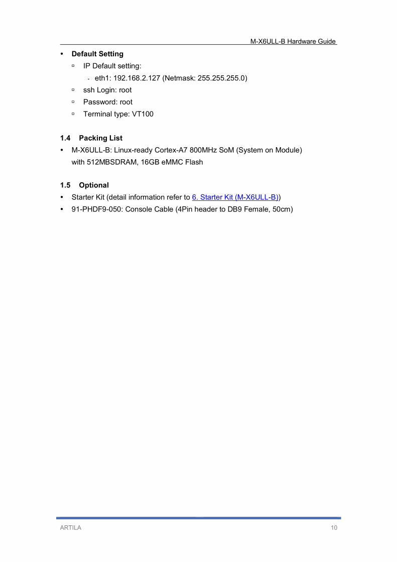
Default Setting
IP Default setting:
� eth1: 192.168.2.127 (Netmask: 255.255.255.0)
ssh Login: root
Password: root
Terminal type: VT100
1.4 Packing List
M-X6ULL-B: Linux-ready Cortex-A7 800MHz SoM (System on Module)
with 512MBSDRAM, 16GB eMMC Flash
1.5 Optional
Starter Kit (detail information refer to 6. Starter Kit (M-X6ULL-B))
91-PHDF9-050: Console Cable (4Pin header to DB9 Female, 50cm)
M-X6ULL-B Hardware Guide
ARTILA 11
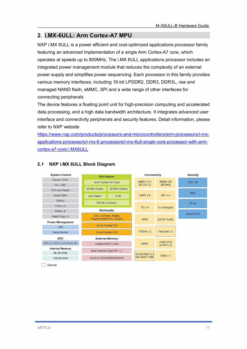
2. i.MX-6ULL: Arm Cortex-A7 MPU
NXP i.MX 6ULL is a power efficient and cost-optimized applications processor family
featuring an advanced implementation of a single Arm Cortex-A7 core, which
operates at speeds up to 800MHz. The i.MX 6ULL applications processor includes an
integrated power management module that reduces the complexity of an external
power supply and simplifies power sequencing. Each processor in this family provides
various memory interfaces, including 16-bit LPDDR2, DDR3, DDR3L, raw and
managed NAND flash, eMMC, SPI and a wide range of other interfaces for
connecting peripherals
The device features a floating point unit for high-precision computing and accelerated
data processing, and a high data bandwidth architecture. It integrates advanced user
interface and connectivity peripherals and security features. Detail information, please
refer to NXP website
https://www.nxp.com/products/processors-and-microcontrollers/arm-processors/i-mx-
applications-processors/i-mx-6-processors/i-mx-6ull-single-core-processor-with-arm-
cortex-a7-core:i.MX6ULL
2.1 NXP i.MX 6ULL Block Diagram
M-X6ULL-B Hardware Guide
ARTILA 12
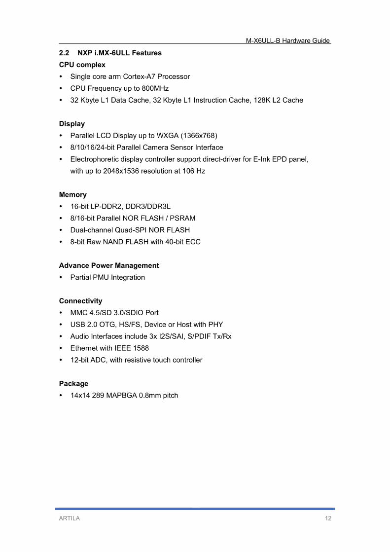
2.2 NXP i.MX-6ULL Features
CPU complex
Single core arm Cortex-A7 Processor
CPU Frequency up to 800MHz
32 Kbyte L1 Data Cache, 32 Kbyte L1 Instruction Cache, 128K L2 Cache
Display
Parallel LCD Display up to WXGA (1366x768)
8/10/16/24-bit Parallel Camera Sensor Interface
Electrophoretic display controller support direct-driver for E-Ink EPD panel,
with up to 2048x1536 resolution at 106 Hz
Memory
16-bit LP-DDR2, DDR3/DDR3L
8/16-bit Parallel NOR FLASH / PSRAM
Dual-channel Quad-SPI NOR FLASH
8-bit Raw NAND FLASH with 40-bit ECC
Advance Power Management
Partial PMU Integration
Connectivity
MMC 4.5/SD 3.0/SDIO Port
USB 2.0 OTG, HS/FS, Device or Host with PHY
Audio Interfaces include 3x I2S/SAI, S/PDIF Tx/Rx
Ethernet with IEEE 1588
12-bit ADC, with resistive touch controller
Package
14x14 289 MAPBGA 0.8mm pitch
M-X6ULL-B Hardware Guide
ARTILA 13
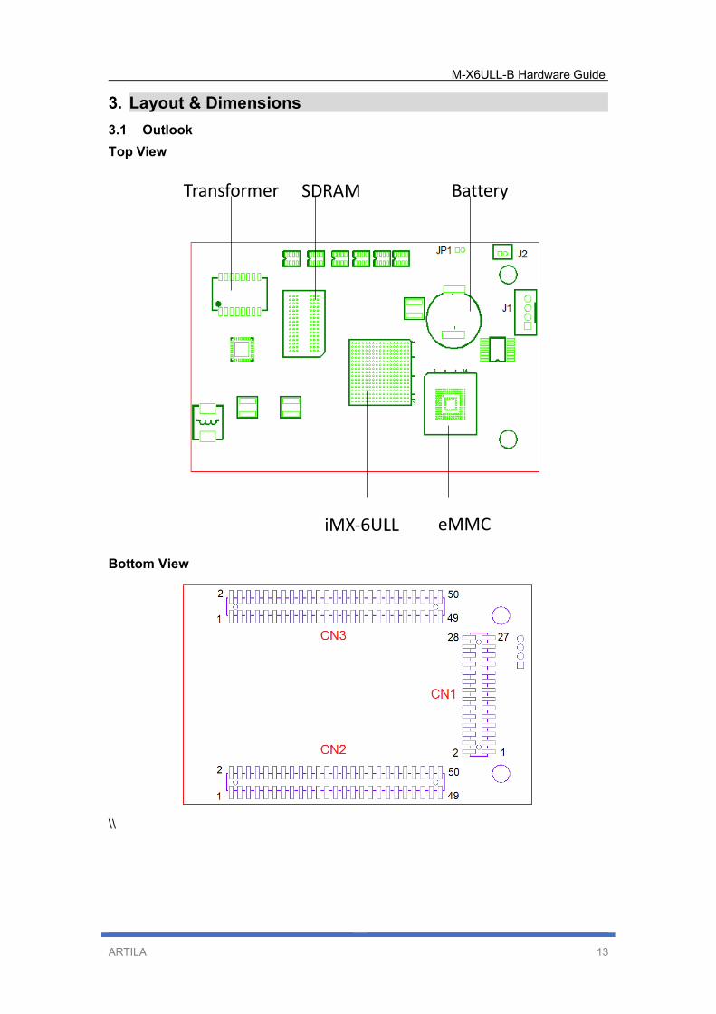
3. Layout & Dimensions
3.1 Outlook
Top View
Bottom View
\\
SDRAM
iMX-6ULL
Battery
eMMC
Transformer
M-X6ULL-B Hardware Guide
ARTILA 14
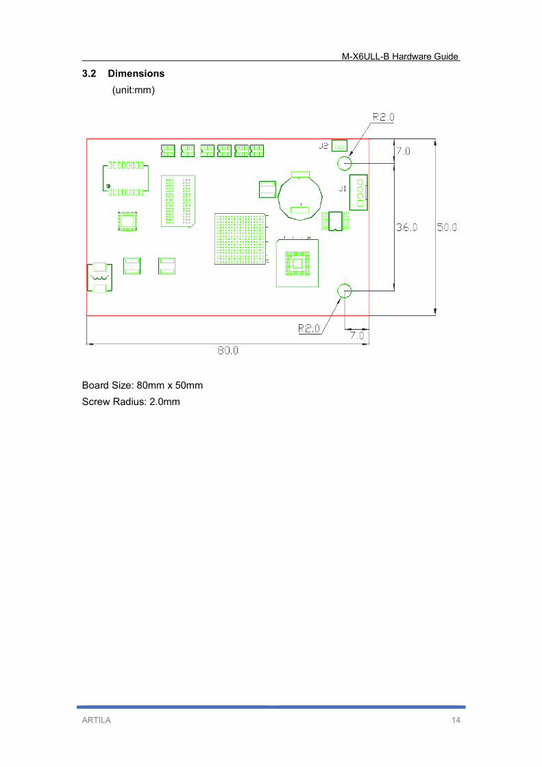
3.2 Dimensions
(unit:mm)
Board Size: 80mm x 50mm
Screw Radius: 2.0mm
M-X6ULL-B Hardware Guide
ARTILA 15
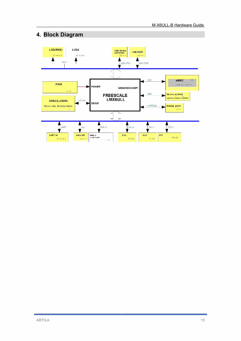
4. Block Diagram
M-X6ULL-B Hardware Guide
ARTILA 16
5. Pin Assignment and Definitions
The M-X6ULL-B exposes three connectors at bottom side that provide I/Os to design
carrier board for versatile application.
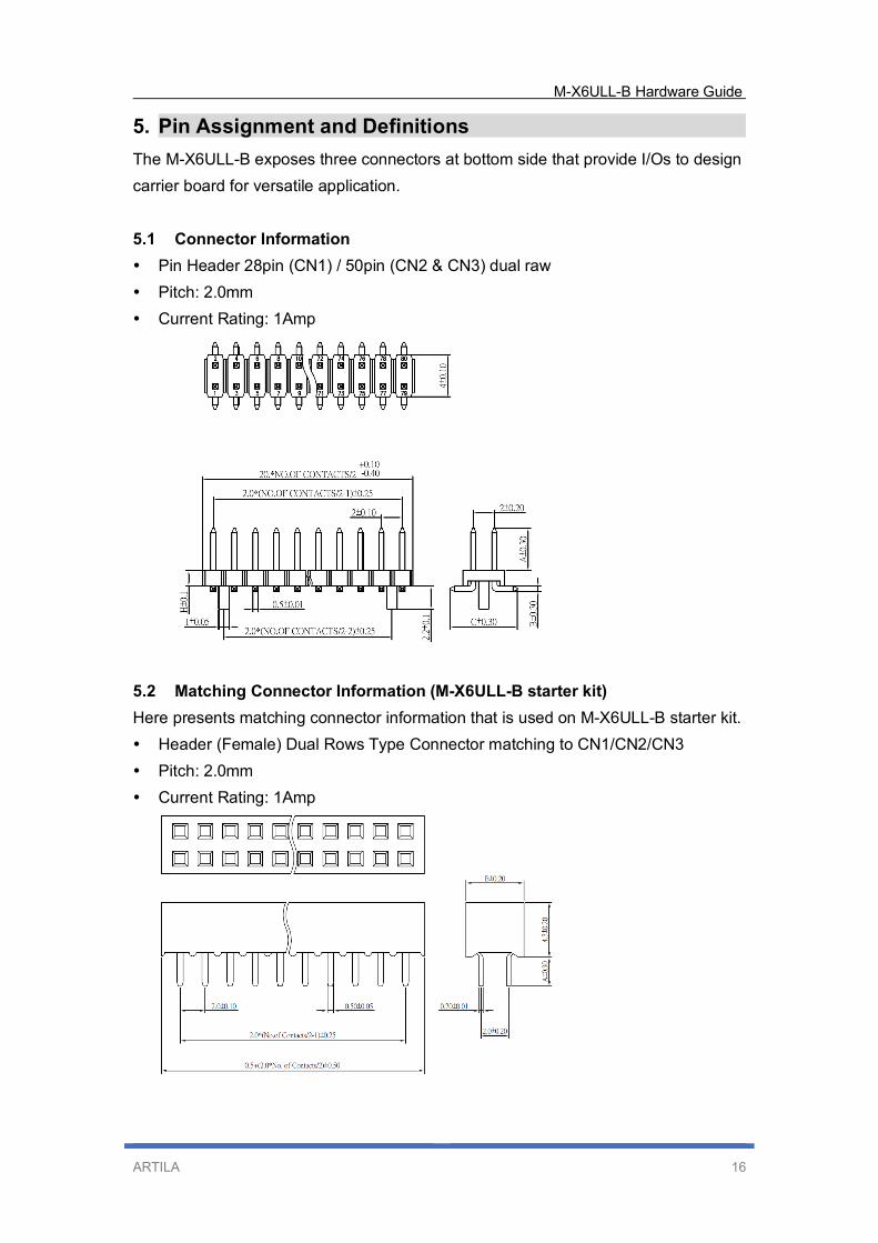
5.1 Connector Information
Pin Header 28pin (CN1) / 50pin (CN2 & CN3) dual raw
Pitch: 2.0mm
Current Rating: 1Amp
5.2 Matching Connector Information (M-X6ULL-B starter kit)
Here presents matching connector information that is used on M-X6ULL-B starter kit.
Header (Female) Dual Rows Type Connector matching to CN1/CN2/CN3
Pitch: 2.0mm
Current Rating: 1Amp
M-X6ULL-B Hardware Guide
ARTILA 17
5.3 Connector and PIN definition
Following shows connector information and pin definition.
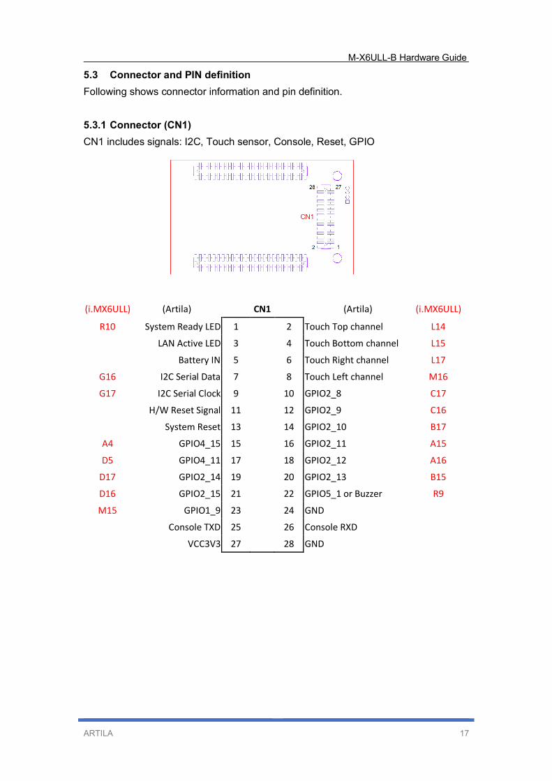
5.3.1 Connector (CN1)
CN1 includes signals: I2C, Touch sensor, Console, Reset, GPIO
(i.MX6ULL) (Artila) CN1
(Artila) (i.MX6ULL)
R10 System Ready LED 1 2 Touch Top channel L14
LAN Active LED 3 4 Touch Bottom channel L15
Battery IN 5 6 Touch Right channel L17
G16 I2C Serial Data 7 8 Touch Left channel M16
G17 I2C Serial Clock 9 10 GPIO2_8 C17
H/W Reset Signal 11 12 GPIO2_9 C16
System Reset 13 14 GPIO2_10 B17
A4 GPIO4_15 15 16 GPIO2_11 A15
D5 GPIO4_11 17 18 GPIO2_12 A16
D17 GPIO2_14 19 20 GPIO2_13 B15
D16 GPIO2_15 21 22 GPIO5_1 or Buzzer R9
M15 GPIO1_9 23 24 GND
Console TXD 25 26 Console RXD
VCC3V3 27 28 GND
M-X6ULL-B Hardware Guide
ARTILA 18
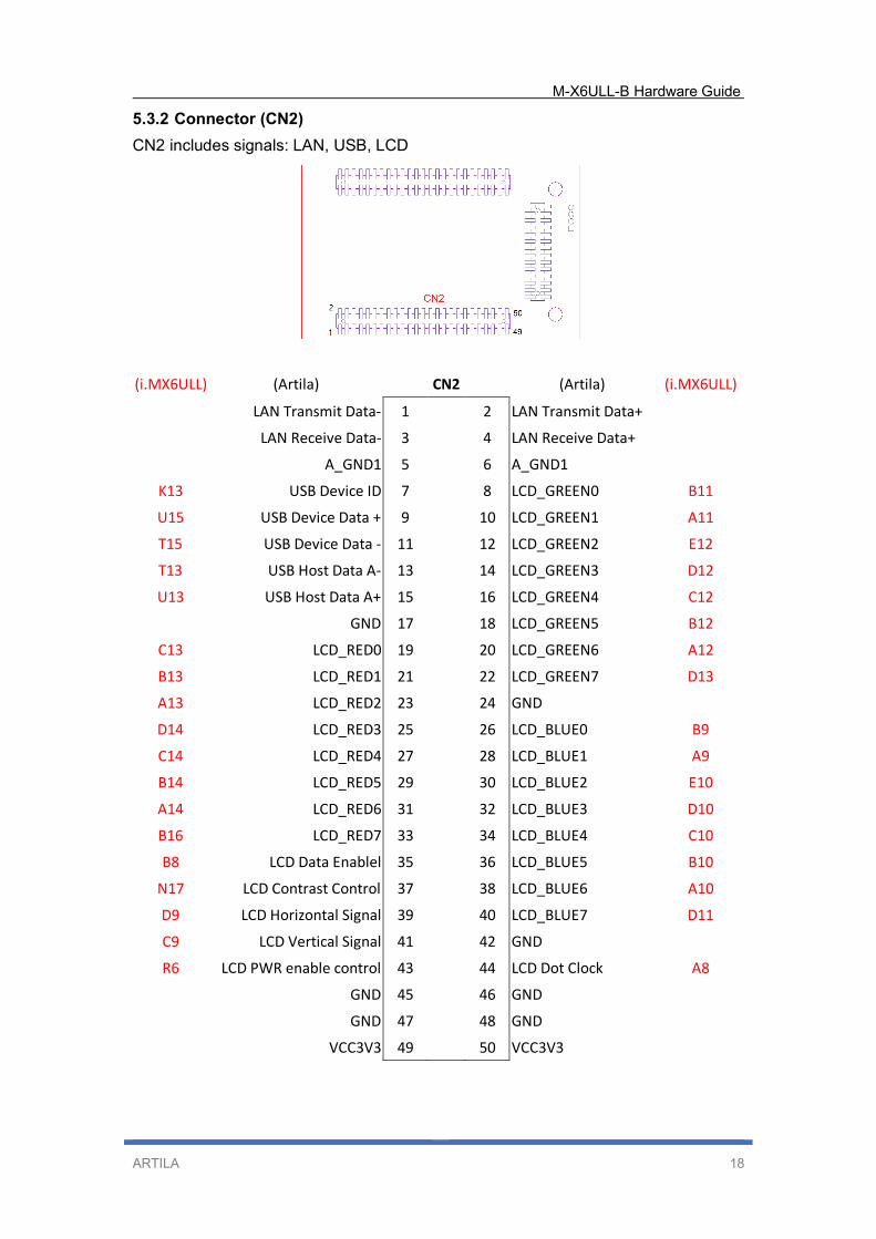
5.3.2 Connector (CN2)
CN2 includes signals: LAN, USB, LCD
(i.MX6ULL) (Artila) CN2
(Artila) (i.MX6ULL)
LAN Transmit Data- 1 2 LAN Transmit Data+
LAN Receive Data- 3 4 LAN Receive Data+
A_GND1 5 6 A_GND1
K13 USB Device ID 7 8 LCD_GREEN0 B11
U15 USB Device Data + 9 10 LCD_GREEN1 A11
T15 USB Device Data - 11 12 LCD_GREEN2 E12
T13 USB Host Data A- 13 14 LCD_GREEN3 D12
U13 USB Host Data A+ 15 16 LCD_GREEN4 C12
GND 17 18 LCD_GREEN5 B12
C13 LCD_RED0 19 20 LCD_GREEN6 A12
B13 LCD_RED1 21 22 LCD_GREEN7 D13
A13 LCD_RED2 23 24 GND
D14 LCD_RED3 25 26 LCD_BLUE0 B9
C14 LCD_RED4 27 28 LCD_BLUE1 A9
B14 LCD_RED5 29 30 LCD_BLUE2 E10
A14 LCD_RED6 31 32 LCD_BLUE3 D10
B16 LCD_RED7 33 34 LCD_BLUE4 C10
B8 LCD Data Enablel 35 36 LCD_BLUE5 B10
N17 LCD Contrast Control 37 38 LCD_BLUE6 A10
D9 LCD Horizontal Signal 39 40 LCD_BLUE7 D11
C9 LCD Vertical Signal 41 42 GND
R6 LCD PWR enable control 43 44 LCD Dot Clock A8
GND 45 46 GND
GND 47 48 GND
VCC3V3 49 50 VCC3V3
M-X6ULL-B Hardware Guide
ARTILA 19
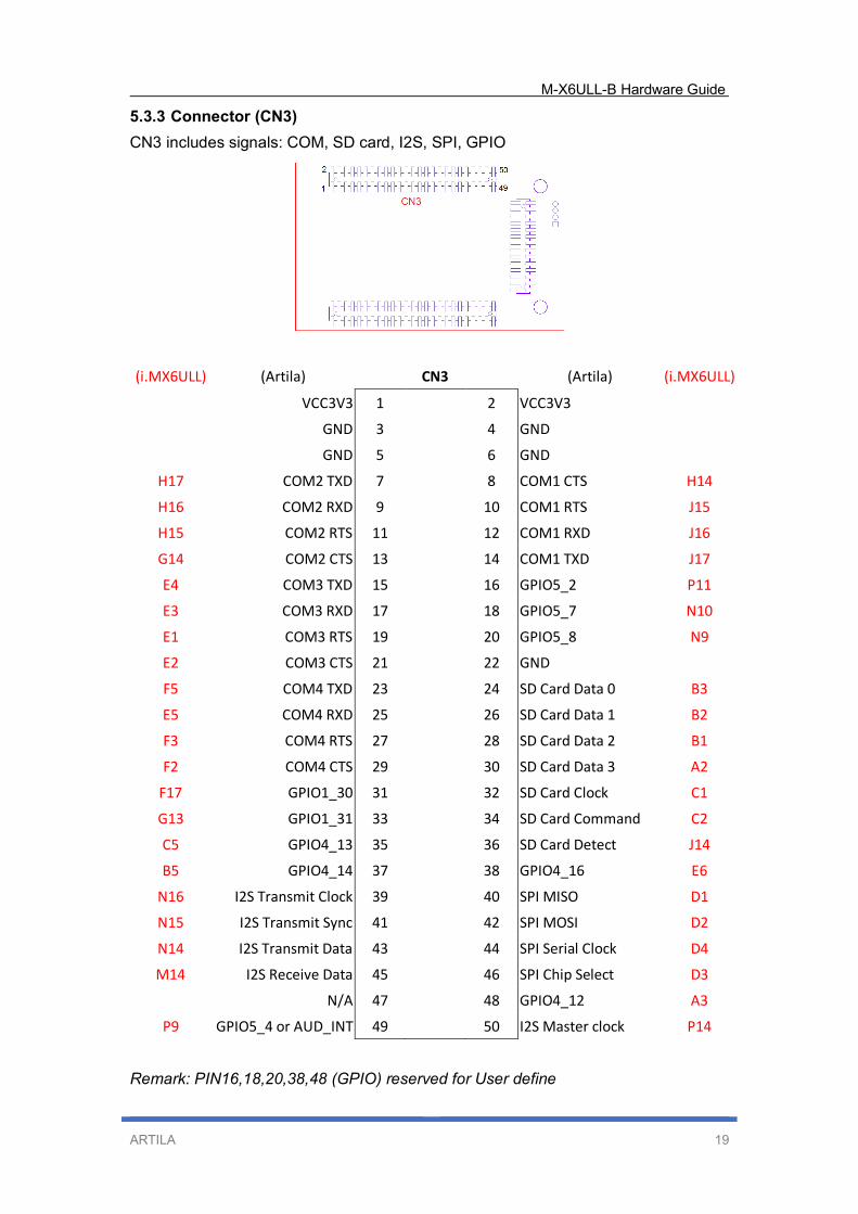
5.3.3 Connector (CN3)
CN3 includes signals: COM, SD card, I2S, SPI, GPIO
(i.MX6ULL) (Artila) CN3
(Artila) (i.MX6ULL)
VCC3V3 1 2 VCC3V3
GND 3 4 GND
GND 5 6 GND
H17 COM2 TXD 7 8 COM1 CTS H14
H16 COM2 RXD 9 10 COM1 RTS J15
H15 COM2 RTS 11 12 COM1 RXD J16
G14 COM2 CTS 13 14 COM1 TXD J17
E4 COM3 TXD 15 16 GPIO5_2 P11
E3 COM3 RXD 17 18 GPIO5_7 N10
E1 COM3 RTS 19 20 GPIO5_8 N9
E2 COM3 CTS 21 22 GND
F5 COM4 TXD 23 24 SD Card Data 0 B3
E5 COM4 RXD 25 26 SD Card Data 1 B2
F3 COM4 RTS 27 28 SD Card Data 2 B1
F2 COM4 CTS 29 30 SD Card Data 3 A2
F17 GPIO1_30 31 32 SD Card Clock C1
G13 GPIO1_31 33 34 SD Card Command C2
C5 GPIO4_13 35 36 SD Card Detect J14
B5 GPIO4_14 37 38 GPIO4_16 E6
N16 I2S Transmit Clock 39 40 SPI MISO D1
N15 I2S Transmit Sync 41 42 SPI MOSI D2
N14 I2S Transmit Data 43 44 SPI Serial Clock D4
M14 I2S Receive Data 45 46 SPI Chip Select D3
N/A 47 48 GPIO4_12 A3
P9 GPIO5_4 or AUD_INT 49 50 I2S Master clock P14
Remark: PIN16,18,20,38,48 (GPIO) reserved for User define
M-X6ULL-B Hardware Guide
ARTILA 20
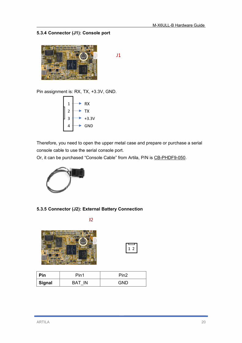
5.3.4 Connector (J1): Console port
Pin assignment is: RX, TX, +3.3V, GND.
Therefore, you need to open the upper metal case and prepare or purchase a serial
console cable to use the serial console port.
Or, it can be purchased “Console Cable” from Artila, P/N is CB-PHDF9-050.
5.3.5 Connector (J2): External Battery Connection
Pin Pin1 Pin2
Signal BAT_IN GND
1
2
3
4
RX
TX
+3.3V
GND
M-X6ULL-B Hardware Guide
ARTILA 21
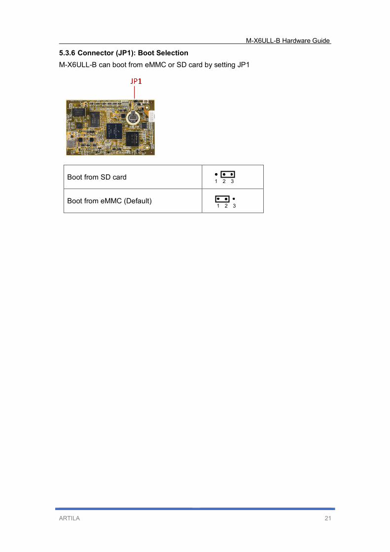
5.3.6 Connector (JP1): Boot Selection
M-X6ULL-B can boot from eMMC or SD card by setting JP1
Boot from SD card
Boot from eMMC (Default)
1 2 3
1 2 3
M-X6ULL-B Hardware Guide
ARTILA 22
6. Starter Kit (M-X6ULL-B)
EV-9G45-A is an evaluation board for M-X6ULL-B. It serves as a complete
development kit for evaluation and application development purposes.
6.1 Features
Support M-X6ULL-B System On Module
1x 10/100Mbps Ethernet port (RJ45), Ethernet IP address: 192.168.2.127
4x USB 2.0 high speed (480Mbps) Host ports and 1x USB Client
4x RS-232/485 serial ports
1x Serial console port
External Battery Socket: Use 3V CR2032 (Battery is not included)
LCD display interface
Backlight power 12V/5Vdc
Touch sensor
Audio In / Out
Reset button
One microSD socket reserved
Real Time Clock
GPIO
Buzzer
+12VDC power input (DC Jack)
M-X6ULL-B Hardware Guide
ARTILA 23
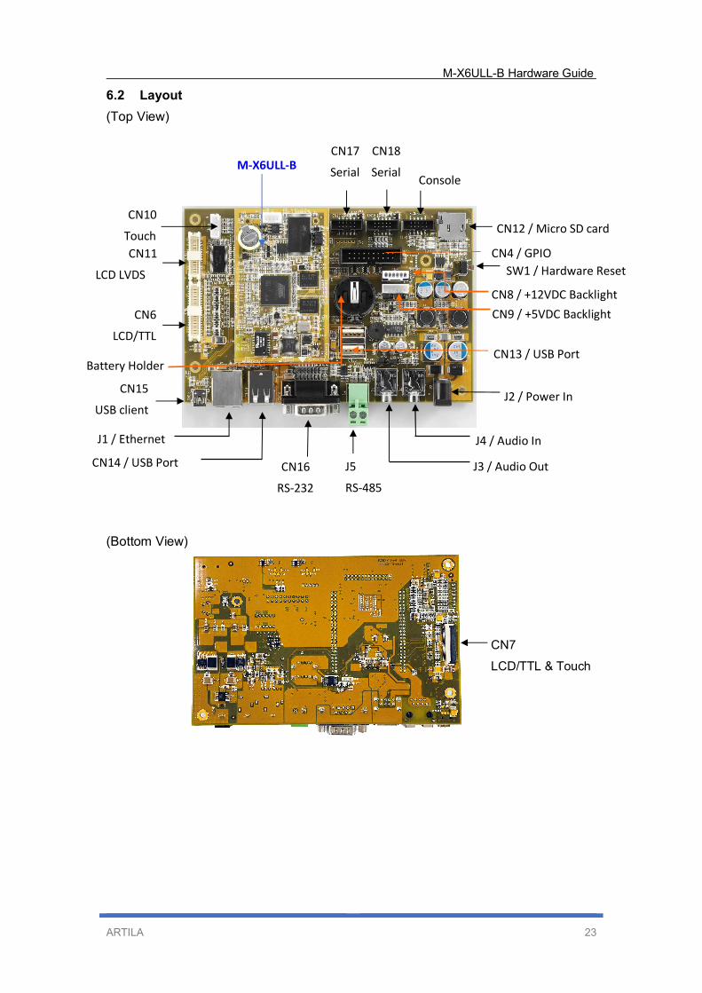
6.2 Layout
(Top View)
(Bottom View)
CN6
LCD/TTL
CN11
LCD LVDS
CN17
Serial
port
M-X6ULL-B
CN18
Serial
port Console
CN12 / Micro SD card
SW1 / Hardware Reset
CN4 / GPIO
CN8 / +12VDC Backlight
CN13 / USB Port
J5
RS-485
J3 / Audio Out
J4 / Audio In
J2 / Power In
CN16
RS-232
CN14 / USB Port
J1 / Ethernet
CN15
USB client
Battery Holder
CN10
Touch
CN9 / +5VDC Backlight
CN7
LCD/TTL & Touch
M-X6ULL-B Hardware Guide
ARTILA 24
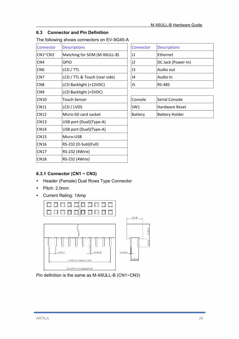
6.3 Connector and Pin Definition
The following shows connectors on EV-9G45-A
Connector Descriptions Connector Descriptions
CN1~CN3 Matching for SOM (M-X6ULL-B) J1 Ethernet
CN4 GPIO J2 DC Jack (Power-In)
CN6 LCD / TTL J3 Audio out
CN7 LCD / TTL & Touch (rear side) J4 Audio In
CN8 LCD Backlight (+12VDC) J5 RS-485
CN9 LCD Backlight (+5VDC)
CN10 Touch Sensor Console Serial Console
CN11 LCD / LVDS SW1 Hardware Reset
CN12 Micro-SD card socket Battery Battery Holder
CN13 USB port (Dual)(Type-A)
CN14 USB port (Dual)(Type-A)
CN15 Micro-USB
CN16 RS-232 (D-Sub)(Full)
CN17 RS-232 (4Wire)
CN18 RS-232 (4Wire)
6.3.1 Connector (CN1 ~ CN3)
Header (Female) Dual Rows Type Connector
Pitch: 2.0mm
Current Rating: 1Amp
Pin definition is the same as M-X6ULL-B (CN1~CN3)
M-X6ULL-B Hardware Guide
ARTILA 25
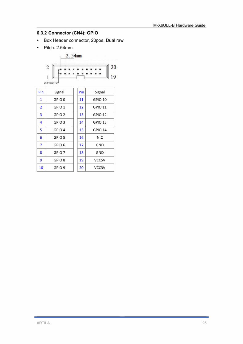
6.3.2 Connector (CN4): GPIO
Box Header connector, 20pos, Dual raw
Pitch: 2.54mm
Pin Signal Pin Signal
1 GPIO 0 11 GPIO 10
2 GPIO 1 12 GPIO 11
3 GPIO 2 13 GPIO 12
4 GPIO 3 14 GPIO 13
5 GPIO 4 15 GPIO 14
6 GPIO 5 16 N.C
7 GPIO 6 17 GND
8 GPIO 7 18 GND
9 GPIO 8 19 VCC5V
10 GPIO 9 20 VCC3V
M-X6ULL-B Hardware Guide
ARTILA 26
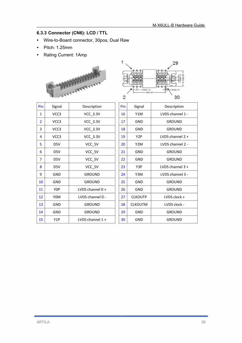
6.3.3 Connector (CN6): LCD / TTL
Wire-to-Board connector, 30pos, Dual Raw
Pitch: 1.25mm
Rating Current: 1Amp
Pin Signal Description Pin Signal Description
1 VCC3 VCC_3.3V 16 Y1M LVDS channel 1 -
2 VCC3 VCC_3.3V 17 GND GROUND
3 VCC3 VCC_3.3V 18 GND GROUND
4 VCC3 VCC_3.3V 19 Y2P LVDS channel 2 +
5 D5V VCC_5V 20 Y2M LVDS channel 2 -
6 D5V VCC_5V 21 GND GROUND
7 D5V VCC_5V 22 GND GROUND
8 D5V VCC_5V 23 Y3P LVDS channel 3 +
9 GND GROUND 24 Y3M LVDS channel 3 -
10 GND GROUND 25 GND GROUND
11 Y0P LVDS channel 0 + 26 GND GROUND
12 Y0M LVDS channel 0 - 27 CLKOUTP LVDS clock +
13 GND GROUND 28 CLKOUTM LVDS clock -
14 GND GROUND 29 GND GROUND
15 Y1P LVDS channel 1 + 30 GND GROUND
M-X6ULL-B Hardware Guide
ARTILA 27
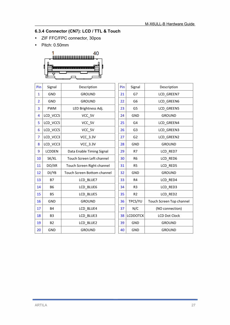
6.3.4 Connector (CN7): LCD / TTL & Touch
ZIF FFC/FPC connector, 30pos
Pitch: 0.50mm
Pin Signal Description Pin Signal Description
1 GND GROUND 21 G7 LCD_GREEN7
2 GND GROUND 22 G6 LCD_GREEN6
3 PWM LED Brightness Adj. 23 G5 LCD_GREEN5
4 LCD_VCC5 VCC_5V 24 GND GROUND
5 LCD_VCC5 VCC_5V 25 G4 LCD_GREEN4
6 LCD_VCC5 VCC_5V 26 G3 LCD_GREEN3
7 LCD_VCC3 VCC_3.3V 27 G2 LCD_GREEN2
8 LCD_VCC3 VCC_3.3V 28 GND GROUND
9 LCDDEN Data Enable Timing Signal 29 R7 LCD_RED7
10 SK/XL Touch Screen Left channel 30 R6 LCD_RED6
11 DO/XR Touch Screen Right channel 31 R5 LCD_RED5
12 DI/YB Touch Screen Bottom channel 32 GND GROUND
13 B7 LCD_BLUE7 33 R4 LCD_RED4
14 B6 LCD_BLUE6 34 R3 LCD_RED3
15 B5 LCD_BLUE5 35 R2 LCD_RED2
16 GND GROUND 36 TPCS/YU Touch Screen Top channel
17 B4 LCD_BLUE4 37 N/C (NO connection)
18 B3 LCD_BLUE3 38 LCDDOTCK LCD Dot Clock
19 B2 LCD_BLUE2 39 GND GROUND
20 GND GROUND 40 GND GROUND
M-X6ULL-B Hardware Guide
ARTILA 28
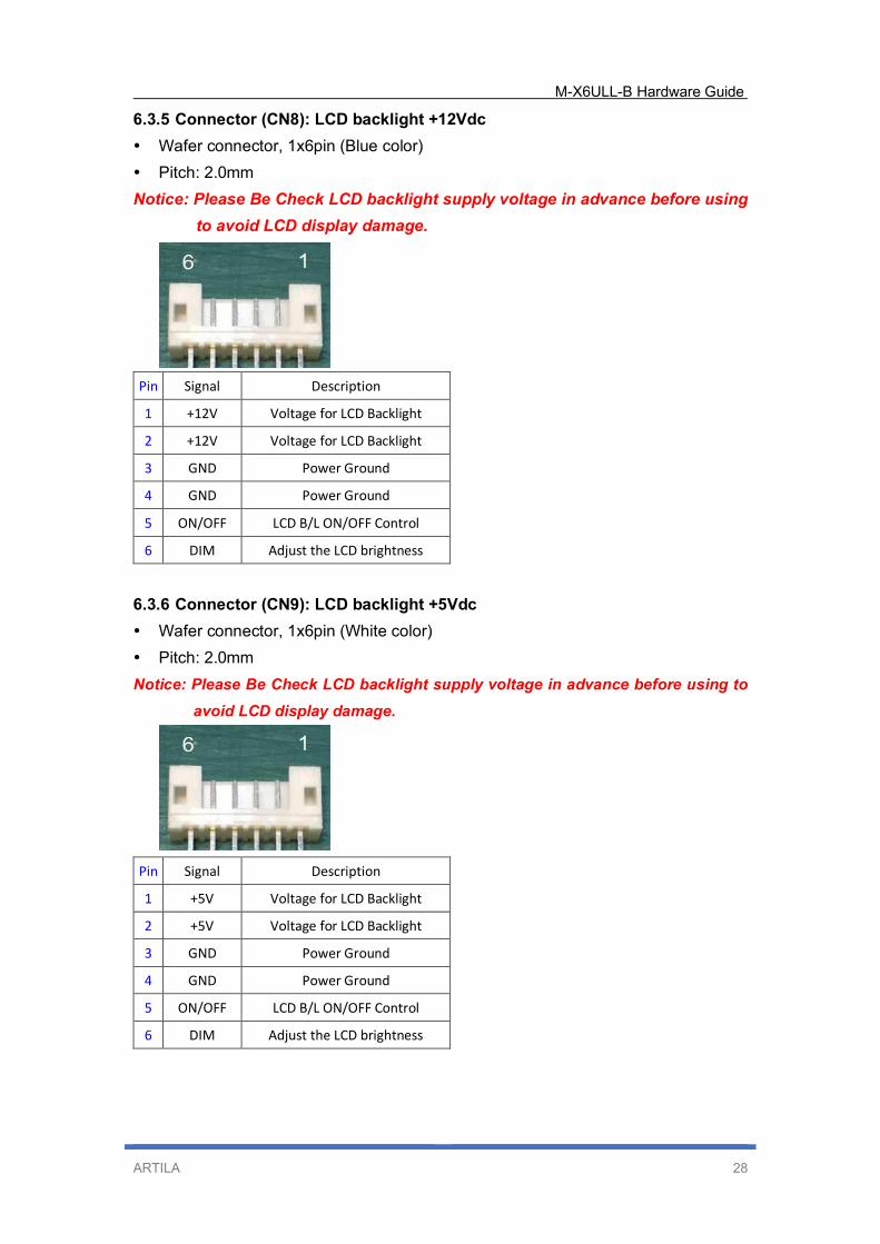
6.3.5 Connector (CN8): LCD backlight +12Vdc
Wafer connector, 1x6pin (Blue color)
Pitch: 2.0mm
Notice: Please Be Check LCD backlight supply voltage in advance before using
to avoid LCD display damage.
Pin Signal Description
1 +12V Voltage for LCD Backlight
2 +12V Voltage for LCD Backlight
3 GND Power Ground
4 GND Power Ground
5 ON/OFF LCD B/L ON/OFF Control
6 DIM Adjust the LCD brightness
6.3.6 Connector (CN9): LCD backlight +5Vdc
Wafer connector, 1x6pin (White color)
Pitch: 2.0mm
Notice: Please Be Check LCD backlight supply voltage in advance before using to
avoid LCD display damage.
Pin Signal Description
1 +5V Voltage for LCD Backlight
2 +5V Voltage for LCD Backlight
3 GND Power Ground
4 GND Power Ground
5 ON/OFF LCD B/L ON/OFF Control
6 DIM Adjust the LCD brightness
M-X6ULL-B Hardware Guide
ARTILA 29
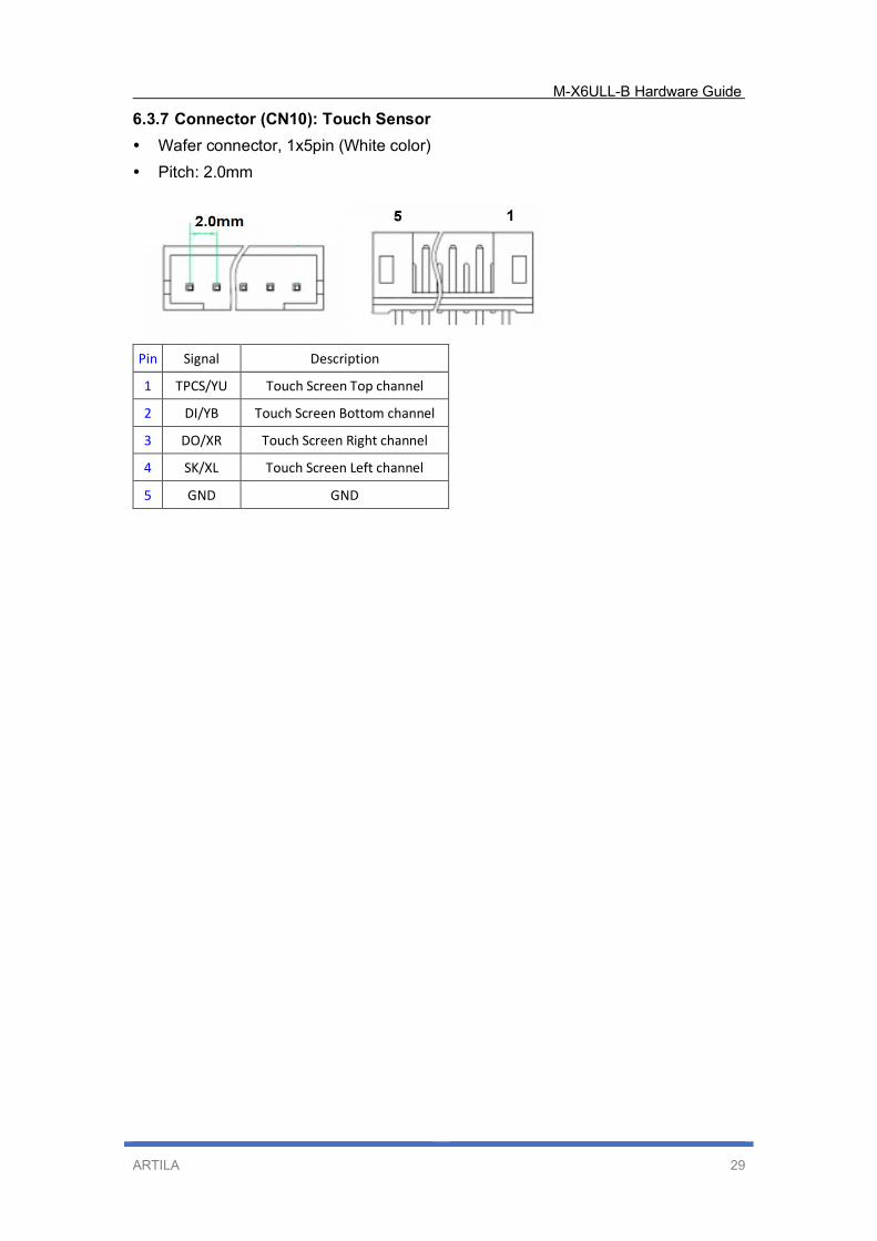
6.3.7 Connector (CN10): Touch Sensor
Wafer connector, 1x5pin (White color)
Pitch: 2.0mm
Pin Signal Description
1 TPCS/YU Touch Screen Top channel
2 DI/YB Touch Screen Bottom channel
3 DO/XR Touch Screen Right channel
4 SK/XL Touch Screen Left channel
5 GND GND
M-X6ULL-B Hardware Guide
ARTILA 30
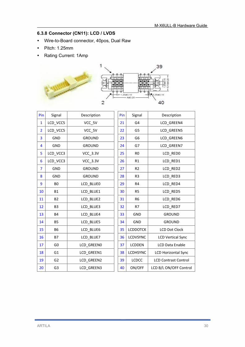
6.3.8 Connector (CN11): LCD / LVDS
Wire-to-Board connector, 40pos, Dual Raw
Pitch: 1.25mm
Rating Current: 1Amp
Pin Signal Description Pin Signal Description
1 LCD_VCC5 VCC_5V 21 G4 LCD_GREEN4
2 LCD_VCC5 VCC_5V 22 G5 LCD_GREEN5
3 GND GROUND 23 G6 LCD_GREEN6
4 GND GROUND 24 G7 LCD_GREEN7
5 LCD_VCC3 VCC_3.3V 25 R0 LCD_RED0
6 LCD_VCC3 VCC_3.3V 26 R1 LCD_RED1
7 GND GROUND 27 R2 LCD_RED2
8 GND GROUND 28 R3 LCD_RED3
9 B0 LCD_BLUE0 29 R4 LCD_RED4
10 B1 LCD_BLUE1 30 R5 LCD_RED5
11 B2 LCD_BLUE2 31 R6 LCD_RED6
12 B3 LCD_BLUE3 32 R7 LCD_RED7
13 B4 LCD_BLUE4 33 GND GROUND
14 B5 LCD_BLUE5 34 GND GROUND
15 B6 LCD_BLUE6 35 LCDDOTCK LCD Dot Clock
16 B7 LCD_BLUE7 36 LCDVSYNC LCD Vertical Sync
17 G0 LCD_GREEN0 37 LCDDEN LCD Data Enable
18 G1 LCD_GREEN1 38 LCDHSYNC LCD Horizontal Sync
19 G2 LCD_GREEN2 39 LCDCC LCD Contrast Control
20 G3 LCD_GREEN3 40 ON/OFF LCD B/L ON/OFF Control
M-X6ULL-B Hardware Guide
ARTILA 31
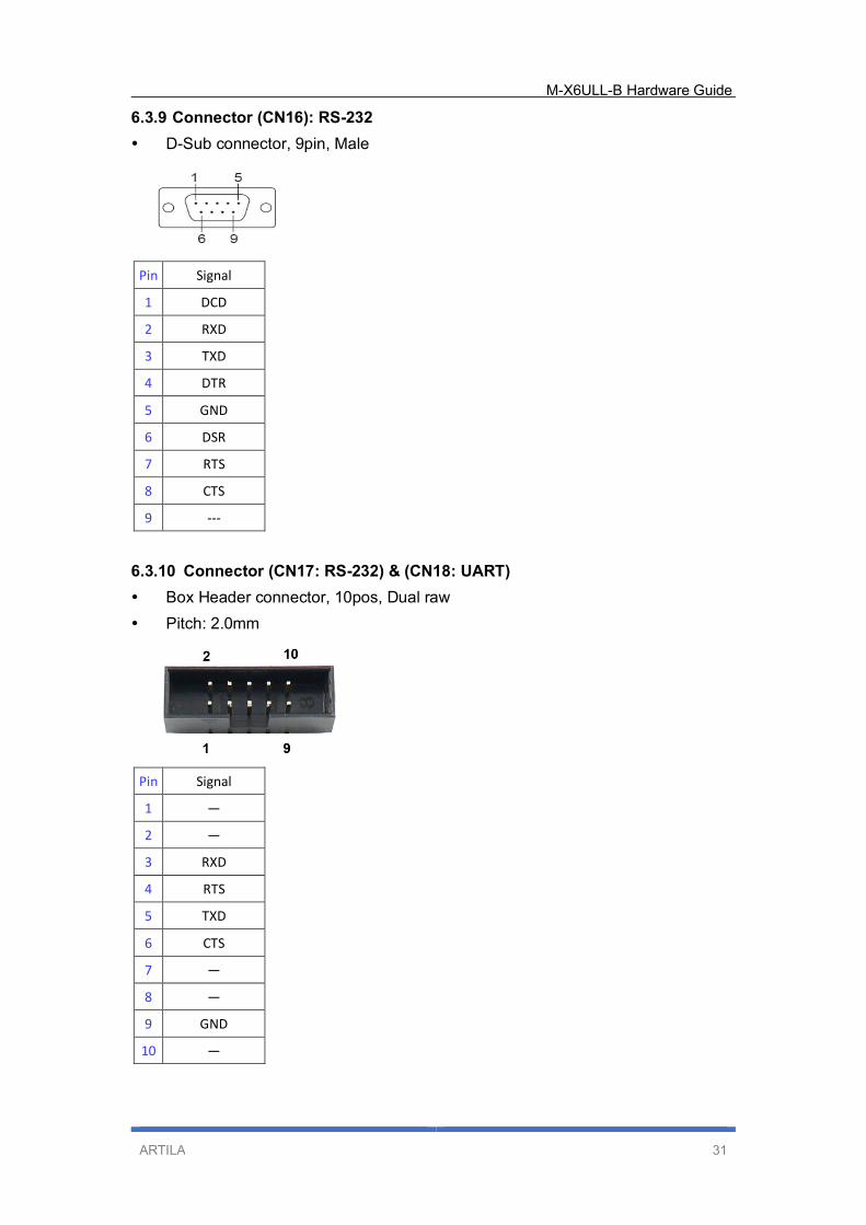
6.3.9 Connector (CN16): RS-232
D-Sub connector, 9pin, Male
Pin Signal
1 DCD
2 RXD
3 TXD
4 DTR
5 GND
6 DSR
7 RTS
8 CTS
9 ---
6.3.10 Connector (CN17: RS-232) & (CN18: UART)
Box Header connector, 10pos, Dual raw
Pitch: 2.0mm
Pin Signal
1 —
2 —
3 RXD
4 RTS
5 TXD
6 CTS
7 —
8 —
9 GND
10 —
M-X6ULL-B Hardware Guide
ARTILA 32
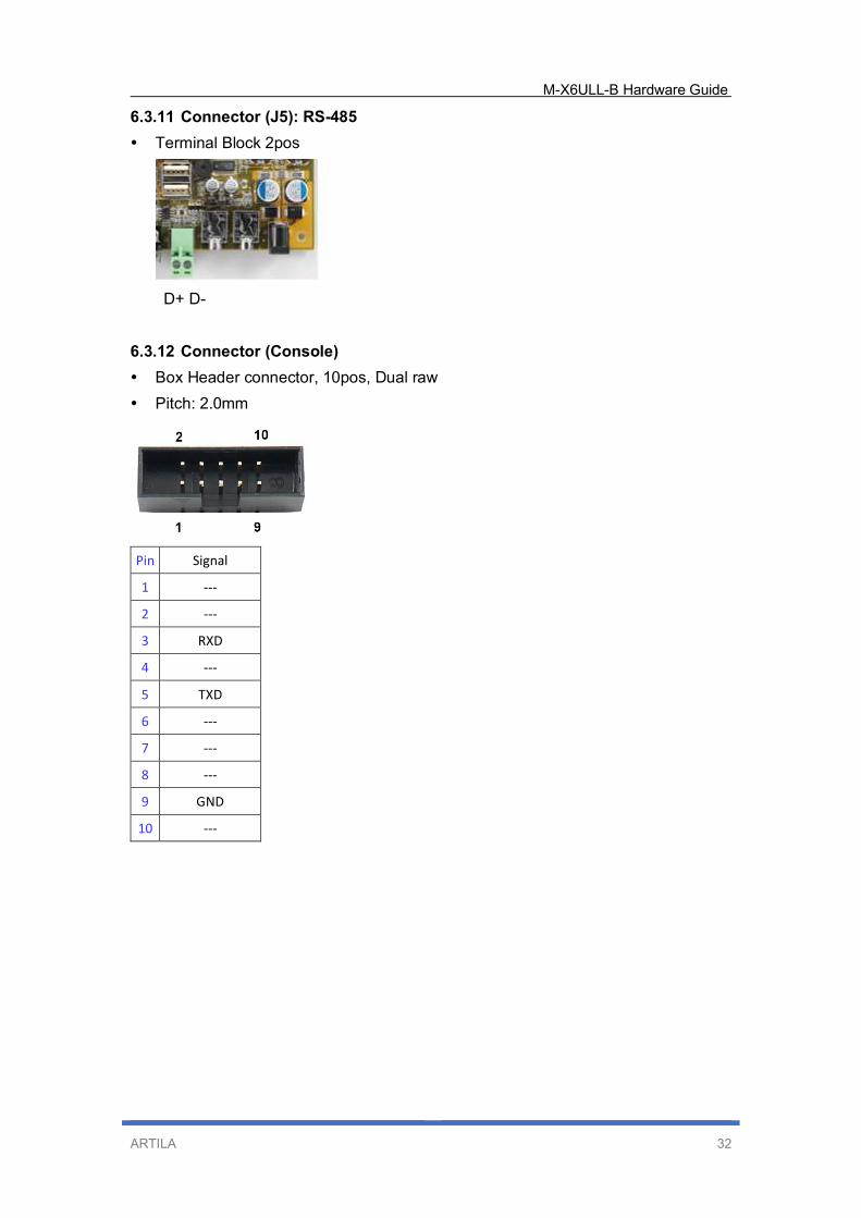
6.3.11 Connector (J5): RS-485
Terminal Block 2pos
6.3.12 Connector (Console)
Box Header connector, 10pos, Dual raw
Pitch: 2.0mm
Pin Signal
1 ---
2 ---
3 RXD
4 ---
5 TXD
6 ---
7 ---
8 ---
9 GND
10 ---
D+ D-
M-X6ULL-B Hardware Guide
ARTILA 33
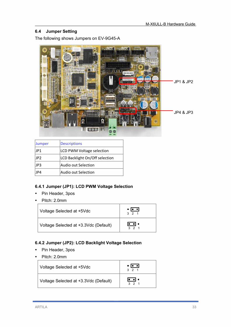
6.4 Jumper Setting
The following shows Jumpers on EV-9G45-A
Jumper Descriptions
JP1 LCD PWM Voltage selection
JP2 LCD Backlight On/Off selection
JP3 Audio out Selection
JP4 Audio out Selection
6.4.1 Jumper (JP1): LCD PWM Voltage Selection
Pin Header, 3pos
Pitch: 2.0mm
Voltage Selected at +5Vdc
Voltage Selected at +3.3Vdc (Default)
6.4.2 Jumper (JP2): LCD Backlight Voltage Selection
Pin Header, 3pos
Pitch: 2.0mm
Voltage Selected at +5Vdc
Voltage Selected at +3.3Vdc (Default)
JP1 & JP2
JP4 & JP3
3 2 1
3 2 1
3 2 1
3 2 1
M-X6ULL-B Hardware Guide
ARTILA 34
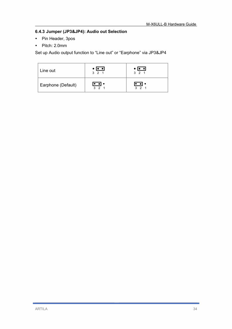
6.4.3 Jumper (JP3&JP4): Audio out Selection
Pin Header, 3pos
Pitch: 2.0mm
Set up Audio output function to “Line out” or “Earphone” via JP3&JP4
Line out
Earphone (Default)
3 2 1
3 2 1
3 2 1
3 2 1
M-X6ULL-B Hardware Guide
ARTILA 35
7. Initial Operation
This guide provides initial information about how to use the EV-9G45-A starter kit to
start up M-X6ULL-B and initial operation with the supplied boot devices.
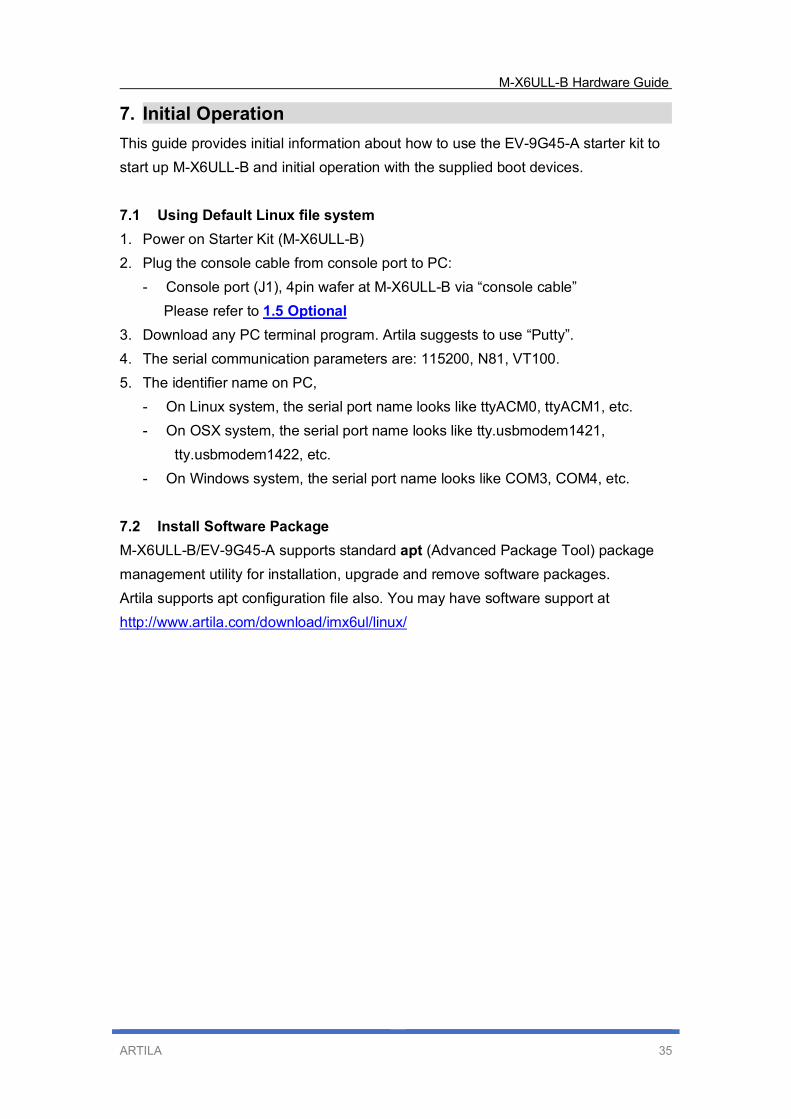
7.1 Using Default Linux file system
1. Power on Starter Kit (M-X6ULL-B)
2. Plug the console cable from console port to PC:
- Console port (J1), 4pin wafer at M-X6ULL-B via “console cable”
Please refer to 1.5 Optional
3. Download any PC terminal program. Artila suggests to use “Putty”.
4. The serial communication parameters are: 115200, N81, VT100.
5. The identifier name on PC,
- On Linux system, the serial port name looks like ttyACM0, ttyACM1, etc.
- On OSX system, the serial port name looks like tty.usbmodem1421,
tty.usbmodem1422, etc.
- On Windows system, the serial port name looks like COM3, COM4, etc.
7.2 Install Software Package
M-X6ULL-B/EV-9G45-A supports standard apt (Advanced Package Tool) package
management utility for installation, upgrade and remove software packages.
Artila supports apt configuration file also. You may have software support at
http://www.artila.com/download/imx6ul/linux/


![Sensing Realitiesrealtechsupport.org/UB/SR/lab_tutorials/raspberrypi.pdf · Windows 10 IoT Core[4] and additional distributions of Linux such as Ubuntu CPU 900 MHz quad-core ARM Cortex-A7](https://img.pdfslide.net/doc/110x75/5f115d69d192501e512e073e/sensing-real-windows-10-iot-core4-and-additional-distributions-of-linux-such-as.jpg)