Embed Size (px)
Citation preview

LIP-ME20X L-IP™ BACnet Router
User Manual
LOYTEC electronics GmbH

Contact
LOYTEC electronics GmbH
Blumengasse 35
1170 Vienna
AUSTRIA/EUROPE
http://www.loytec.com
Version 5.3
Document № 88073508
LOYTEC MAKES AND YOU RECEIVE NO WARRANTIES OR CONDITIONS,
EXPRESS, IMPLIED, STATUTORY OR IN ANY COMMUNICATION WITH YOU,
AND
LOYTEC SPECIFICALLY DISCLAIMS ANY IMPLIED WARRANTY OF
MERCHANTABILITY OR FITNESS FOR A PARTICULAR PURPOSE. THIS PRODUCT IS NOT DESIGNED OR INTENDED FOR USE IN EQUIPMENT
INTENDED FOR SURGICAL IMPLANT INTO THE BODY OR OTHER APPLICATIONS INTENDED TO SUPPORT OR SUSTAIN LIFE, FOR USE IN
FLIGHT CONTROL OR ENGINE CONTROL EQUIPMENT WITHIN AN AIRCRAFT, OR FOR ANY OTHER APPLICATION IN WHICH IN THE FAILURE OF SUCH PRODUCT COULD CREATE A SITUATION IN WHICH PERSONAL
INJURY OR DEATH MAY OCCUR.
No part of this publication may be reproduced, stored in a retrieval system, or transmitted,
in any form or by any means, electronic, mechanical, photocopying, recording, or otherwise,
without the prior written permission of LOYTEC.
LC3020, L-Chip, L-Core, L-DALI, L-GATE, L-INX, L-IOB,
LIOB-Connect, LIOB-FT, L-IP, LPA, L-Proxy, L-Switch, L-Term,
L-VIS, L-WEB, L-ZIBI, ORION™ stack and Smart Auto-Connect™ are
trademarks of LOYTEC electronics GmbH.
LonTalk®, LONWORKS®, Neuron®, LONMARK®, LonMaker®, i.LON®, and LNS® are
trademarks of Echelon Corporation registered in the United States and other countries.

LIP-ME201 User Manual 3 LOYTEC
Version 5.3 LOYTEC electronics GmbH
Contents
1 Introduction .................................................................................................. 9
1.1 Overview .............................................................................................................. 9
1.2 LIP-ME20X Models ............................................................................................ 9
1.3 Scope ................................................................................................................... 10
2 What’s New in LIP-ME20X ...................................................................... 11
2.1 New in LIP-ME20X 5.3.0.................................................................................. 11
2.2 New in LIP-ME20X 5.1.0.................................................................................. 11
3 Quick-Start Guide ...................................................................................... 13
3.1 Hardware Installation and IP Connection ...................................................... 13
3.2 Configuration of the LIP-ME20X .................................................................... 13
3.2.1 Configuration on the Web Interface ......................................................... 13
3.2.2 Configuration on the LCD Display .......................................................... 13
3.3 Remote Protocol Analyzer ................................................................................ 15
3.4 Reset to Factory Defaults .................................................................................. 15
4 Hardware Installation ................................................................................ 16
4.1 Enclosure ............................................................................................................ 16
4.1.1 LIP-ME201 .............................................................................................. 16
4.1.2 LIP-ME201C ........................................................................................... 16
4.1.3 LIP-ME202C ........................................................................................... 17
4.1.4 LIP-ME204 .............................................................................................. 19
4.2 Product Label .................................................................................................... 19
4.2.1 LIP-ME201 .............................................................................................. 19
4.2.2 LIP-ME201C, LIP-ME202C .................................................................... 20
4.2.3 LIP-ME204 .............................................................................................. 20
4.3 Mounting ............................................................................................................ 21
4.4 LED signals ........................................................................................................ 21
4.4.1 Power LED .............................................................................................. 21
4.4.2 Status LED ............................................................................................... 21
4.4.3 MSTP Activity LED ................................................................................ 21
4.4.4 Ethernet Link LED ................................................................................... 21
4.4.5 Ethernet Activity LED ............................................................................. 21
4.4.6 BACnet/IP LED ....................................................................................... 21
4.4.7 BBMD LED ............................................................................................. 22
4.5 Status Button ..................................................................................................... 22
4.6 LCD Display and Jog Dial ................................................................................ 22
LIP-ME201 User Manual 4 LOYTEC
Version 5.3 LOYTEC electronics GmbH
4.7 DIP Switch Settings .......................................................................................... 23
4.8 Terminal Layout and Power Supply ............................................................... 24
4.8.1 LIP-ME201.............................................................................................. 24
4.9 Wiring ................................................................................................................ 24
4.9.1 LIP-ME201.............................................................................................. 24
4.9.2 LIP-ME201C, LIP-ME202C ................................................................... 25
4.9.3 LIP-ME204.............................................................................................. 26
5 Web Interface ............................................................................................. 28
5.1 Device Information and Account Management ............................................. 28
5.2 Device Configuration ........................................................................................ 30
5.2.1 System Configuration .............................................................................. 30
5.2.2 Backup and Restore ................................................................................. 31
5.2.3 Port Configuration ................................................................................... 32
5.2.4 IP Configuration ...................................................................................... 32
5.2.5 Using Multiple IP Ports ........................................................................... 34
5.2.6 IP Host Configuration .............................................................................. 34
5.2.7 WLAN Configuration .............................................................................. 35
5.2.8 BACnet Device Configuration................................................................. 40
5.2.9 BACnet/IP Configuration ........................................................................ 41
5.2.10 MS/TP Configuration .............................................................................. 42
5.2.11 BACnet Time Master .............................................................................. 42
5.2.12 BACnet BDT (Broadcast Distribution Table) ......................................... 43
5.2.13 BACnet ACL (Access Control List) ........................................................ 44
5.2.14 BACnet Slave Proxy ................................................................................ 44
5.2.15 Firmware ................................................................................................. 45
5.2.16 SNMP ...................................................................................................... 45
5.2.17 Documentation ........................................................................................ 46
5.3 Device Statistics ................................................................................................. 47
5.3.1 System Log .............................................................................................. 47
5.3.2 IP Statistics .............................................................................................. 47
5.3.3 BACnet MS/TP Statistics ........................................................................ 48
5.3.4 BACnet FDT Statistics ............................................................................ 50
5.3.5 Packet Capture ......................................................................................... 51
5.4 Documentation .................................................................................................. 51
5.5 Reset, Contact, Logout ..................................................................................... 51
6 Operating Interfaces .................................................................................. 52
6.1 BACnet Interface .............................................................................................. 52
6.1.1 Device Object .......................................................................................... 52
6.1.2 Device Name and ID ............................................................................... 53

LIP-ME201 User Manual 5 LOYTEC
Version 5.3 LOYTEC electronics GmbH
6.1.3 Device Information .................................................................................. 53
6.1.4 Object Database ....................................................................................... 54
6.1.5 Protocol Parameters ................................................................................. 54
6.1.6 Diagnostics ............................................................................................... 55
6.1.7 Date & Time ............................................................................................ 56
6.1.8 Time Master ............................................................................................. 56
6.1.9 Backup & Restore .................................................................................... 57
6.1.10 Slave Proxy .............................................................................................. 57
6.2 SNMP Interface ................................................................................................. 58
6.2.1 SNMP Features ........................................................................................ 58
6.2.2 Configuration ........................................................................................... 59
6.2.3 Exposing Data Points to SNMP ............................................................... 60
6.2.4 SNMP Security ........................................................................................ 61
7 Network Media ........................................................................................... 62
7.1 MS/TP ................................................................................................................ 62
7.2 Redundant Ethernet .......................................................................................... 62
7.2.1 Ethernet Cabling Options ......................................................................... 62
7.2.2 Upstream Options .................................................................................... 64
7.2.3 Preconditions ........................................................................................... 64
7.2.4 Switch Settings ......................................................................................... 65
7.2.5 Testing ..................................................................................................... 65
7.2.6 Example switch configuration .................................................................. 66
7.3 WLAN ................................................................................................................ 66
7.3.1 Introduction .............................................................................................. 66
7.3.2 802.11s Mesh Networking ....................................................................... 67
7.3.3 Hardware Installation ............................................................................... 68
8 Firmware Update ........................................................................................ 69
8.1 Firmware Update via FTP ................................................................................ 69
8.2 Firmware Update via the Console ................................................................... 69
8.3 Firmware Update via the Web Interface ......................................................... 70
9 Troubleshooting .......................................................................................... 71
9.1 Technical Support ............................................................................................. 71
9.2 Statistics on the Console ................................................................................... 72
9.2.1 Connecting to the Console ....................................................................... 72
9.2.2 Reset configuration (load factory defaults) .............................................. 72
9.2.3 Device Statistics Menu ............................................................................. 72
9.2.4 IP statistics ............................................................................................... 72
9.2.5 BBMD Communications Test .................................................................. 74
9.3 Packet Capture .................................................................................................. 74

LIP-ME201 User Manual 6 LOYTEC
Version 5.3 LOYTEC electronics GmbH
9.3.1 Configure Remote Packet Capture .......................................................... 74
9.3.2 Enable Local Capture .............................................................................. 74
9.3.3 Run Wireshark Remote Capture .............................................................. 75
10 Security Hardening Guide ......................................................................... 79
10.1 Installation Instructions ................................................................................... 79
10.2 Firmware ........................................................................................................... 79
10.3 Ports ................................................................................................................... 79
10.4 Services .............................................................................................................. 80
10.5 Logging and Auditing ....................................................................................... 80
11 Specifications .............................................................................................. 81
11.1 Physical Specifications ...................................................................................... 81
11.1.1 LIP-ME201.............................................................................................. 81
11.1.2 LIP-ME201C, LIP-ME202C ................................................................... 81
11.1.3 LIP-ME204.............................................................................................. 82
11.2 Resource Limits................................................................................................. 82
11.3 Removable Media ............................................................................................. 82
11.3.1 LIP-ME204.............................................................................................. 82
12 References ................................................................................................... 83
13 Revision History ......................................................................................... 84
LIP-ME201 User Manual 7 LOYTEC
Version 5.3 LOYTEC electronics GmbH
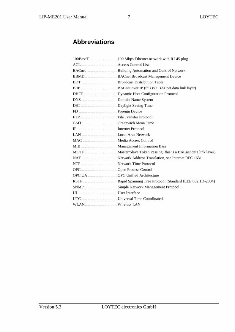
Abbreviations
100BaseT ............................ 100 Mbps Ethernet network with RJ-45 plug
ACL ..................................... Access Control List
BACnet ............................... Building Automation and Control Network
BBMD ................................. BACnet Broadcast Management Device
BDT .................................... Broadcast Distribution Table
B/IP ..................................... BACnet over IP (this is a BACnet data link layer)
DHCP .................................. Dynamic Host Configuration Protocol
DNS .................................... Domain Name System
DST ..................................... Daylight Saving Time
FD ....................................... Foreign Device
FTP ..................................... File Transfer Protocol
GMT.................................... Greenwich Mean Time
IP ......................................... Internet Protocol
LAN .................................... Local Area Network
MAC ................................... Media Access Control
MIB ..................................... Management Information Base
MS/TP ................................. Master/Slave Token Passing (this is a BACnet data link layer)
NAT .................................... Network Address Translation, see Internet RFC 1631
NTP ..................................... Network Time Protocol
OPC ..................................... Open Process Control
OPC UA .............................. OPC Unified Architecture
RSTP ................................... Rapid Spanning Tree Protocol (Standard IEEE 802.1D-2004)
SNMP ................................. Simple Network Management Protocol
UI ........................................ User Interface
UTC .................................... Universal Time Coordinated
WLAN ................................. Wireless LAN


LIP-ME20X User Manual 9 LOYTEC
Version 5.3 LOYTEC electronics GmbH
1 Introduction
1.1 Overview
The LIP-ME20X is a BTL-certified BACnet router between MS/TP and B/IP (BACnet over
IP) as well as a BBMD (BACnet Broadcast Management Device) for transportation of
BACnet broadcasts over an IP network with several subnets. Additionally, it can serve as a
BACnet time master and a BACnet MS/TP slave proxy. The LIP-ME20X also provides
additional features such as optional write protection of the BDT, a BACnet/IP access
control list and a simple BBMD communications test to troubleshoot the network. The
MS/TP port supports remote Wireshark packet capture for troubleshooting the MS/TP
channel.
The LIP-ME202C and LIP-ME204 model are true multi-port MS/TP routers that come with
two Ethernet ports and two or four MS/TP ports respectively. The device setup can be done
easily on the LCD display. Each of the MS/TP ports is routed to BACnet/IP and can serve a
full-blown MS/TP channel. Communication settings as well as sophisticated MS/TP token
passing statistics are available on the Web interface per MS/TP port. The remote Wireshark
packet capture feature is also available on each of the MS/TP ports. This makes the LIP-
ME202C and LIP-ME204 a perfect alternative to installing four separate routers, reducing
space and cost.
In addition the LIP-ME20XC and LIP-ME204 models are also equipped with enhanced
security features such as a built-in firewall and a secure Web interface for installation using
HTTPS with self-signed or installable CA certificates. By configuring separate IP networks
on the two Ethernet ports, the BACnet network can be entirely isolated from the
configuration interface.
For perfect integration into building management software such as the LWEB-900 by
LOYTEC, the LIP-ME20XC and LIP-ME204 offers an embedded OPC UA server with
certificate authentication, which exposes important operational parameters as OPC tags. For
enhanced maintainability by IT departments these models provide the same data also
through an SNMP server. Together with the LWLAN-800 adapter the LIP-ME20XC and
LIP-ME204 can operate BACnet/IP on the WLAN. By setting up an access point on the
BACnet/IP network, the device can be used to distribute MS/TP channels on a wireless
network.
1.2 LIP-ME20X Models
This Section provides an overview of the different LIP-ME20X models in Table 1. This
table identifies the different features of those models. Models that possess a certain feature
have a check mark () in the respective column. If a feature is not available in the particular
model, the column is left blank.

LIP-ME20X User Manual 10 LOYTEC
Version 5.3 LOYTEC electronics GmbH
Model
Features LIP
-ME
20
1
LIP
-ME
20
1C
LIP
-ME
20
2C
LIP
-ME
20
4
BACnet Router
MS/TP Ports 1 1 2 4
BBMD
OPC XML-DA
OPC UA
SNMP
LCD Display
Serial Console
SD Card
USB
Ethernet Switch/Hub
WLAN
SSH, HTTPS, Firewall
Table 1: Available features in different LIP-ME20X models.
1.3 Scope
This document covers LIP-ME20X devices.
LIP-ME20X User Manual 11 LOYTEC
Version 5.3 LOYTEC electronics GmbH
2 What’s New in LIP-ME20X
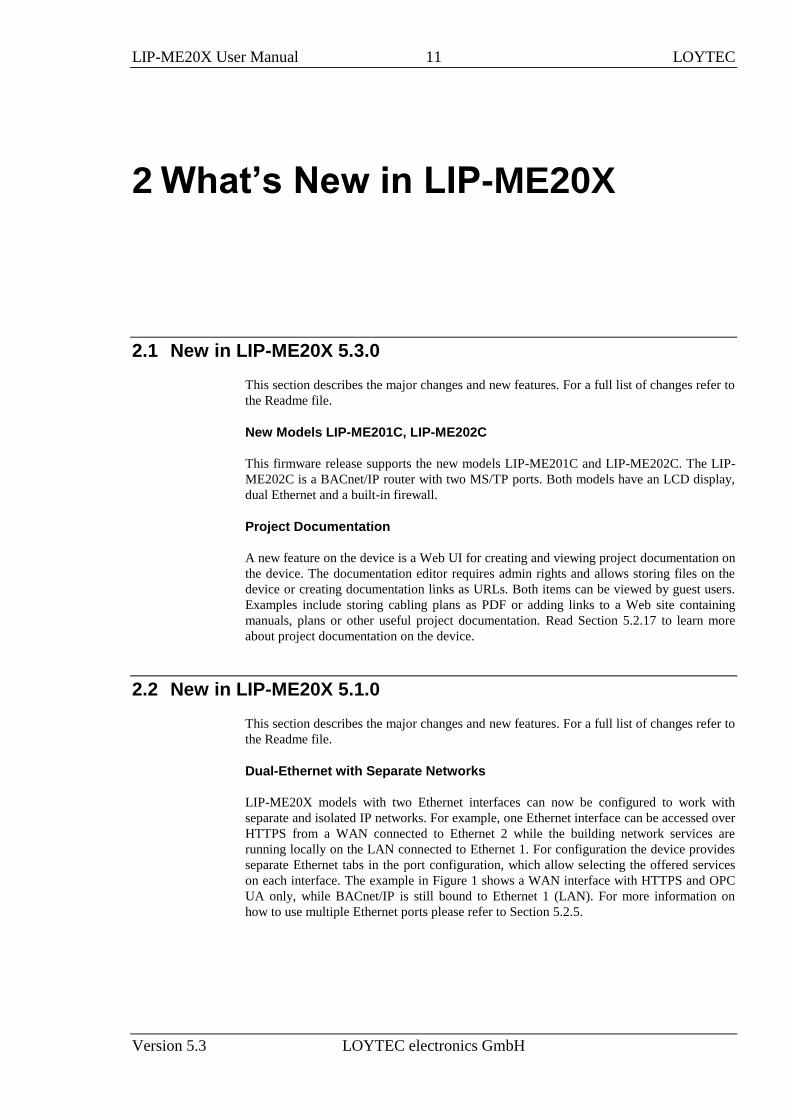
2.1 New in LIP-ME20X 5.3.0
This section describes the major changes and new features. For a full list of changes refer to
the Readme file.
New Models LIP-ME201C, LIP-ME202C
This firmware release supports the new models LIP-ME201C and LIP-ME202C. The LIP-
ME202C is a BACnet/IP router with two MS/TP ports. Both models have an LCD display,
dual Ethernet and a built-in firewall.
Project Documentation
A new feature on the device is a Web UI for creating and viewing project documentation on
the device. The documentation editor requires admin rights and allows storing files on the
device or creating documentation links as URLs. Both items can be viewed by guest users.
Examples include storing cabling plans as PDF or adding links to a Web site containing
manuals, plans or other useful project documentation. Read Section 5.2.17 to learn more
about project documentation on the device.
2.2 New in LIP-ME20X 5.1.0
This section describes the major changes and new features. For a full list of changes refer to
the Readme file.
Dual-Ethernet with Separate Networks
LIP-ME20X models with two Ethernet interfaces can now be configured to work with
separate and isolated IP networks. For example, one Ethernet interface can be accessed over
HTTPS from a WAN connected to Ethernet 2 while the building network services are
running locally on the LAN connected to Ethernet 1. For configuration the device provides
separate Ethernet tabs in the port configuration, which allow selecting the offered services
on each interface. The example in Figure 1 shows a WAN interface with HTTPS and OPC
UA only, while BACnet/IP is still bound to Ethernet 1 (LAN). For more information on
how to use multiple Ethernet ports please refer to Section 5.2.5.

LIP-ME20X User Manual 12 LOYTEC
Version 5.3 LOYTEC electronics GmbH
Figure 1: New Ethernet 2 (WAN) tab
WLAN Interface
In combination with the external LWLAN-800 interface, the device provides new interface
tabs for wireless IP networks. Similar to the second Ethernet interface, one can choose
which protocols are available on the wireless network. The wireless interface can be
configured as a WLAN client, access point or mesh node. Using the latter, a wireless mesh
network of LOYTEC devices can be built. Please refer to Section 5.2.7 to learn more about
the WLAN interface.
Web Interface
The Web interface of the device offers a number of new features:
A new device info page provides a quick overview of all relevant operational
parameters, such as CPU load, active protocols, time synchronization and many more.
A new firmware upgrade menu on the Web interface allows online checking for
firmware updates and upgrading by selecting a local firmware file.
OPC UA Server
The OPC server on the devices, which support security, has been extended by an OPC UA
server. This supports the OPC UA binary protocol and exposes the same OPC tags as the
well-known OPC XML-DA server. In addition OPC UA offers superior security features as
well as slimmer data transfers. For more information on the OPC UA server please refer to
respective Section in the L-INX/L-GATE User Manual [1].
SNMP
For accessing vital operational data in standard IT equipment, LIP-ME20X devices offer an
SNMP management base (MIB). All system registers are available in that MIB. The MIB
file can be downloaded from the device and imported in the SNMP management tool.
Alarms on the device can be exposed as SNMP traps. For more information on configuring
and using SNMP with a LOYTEC device please refer to Section 6.2.

LIP-ME20X User Manual 13 LOYTEC
Version 5.3 LOYTEC electronics GmbH
3 Quick-Start Guide
This chapter provides the minimum list of steps necessary to setup the LIP-ME20X.
3.1 Hardware Installation and IP Connection
Connect power, Ethernet, and MS/TP (Sections 4.8 and 4.9).
Connect the Console (Section 9.2.1) and configure the IP address, netmask, and
gateway or connect to the LIP-ME20X over the Web interface right away (Section 5.1)
and setup the IP configuration there (Section 5.2.4).
On devices with an LCD display enter the IP address using the jog dial.
In both cases, reboot the LIP-ME20X to commit the new IP settings (use corresponding
menu item either in console menu or Web interface).
Important! The default IP address 192.168.1.254 is only set for configuration access. It must be
changed in order to make the device functional.
3.2 Configuration of the LIP-ME20X
3.2.1 Configuration on the Web Interface
Connect to the LIP-ME20X using the new IP address in a Web browser.
Click on Config and enter the default administrator password 'loytec4u'. Note, that
older firmware versions used 'admin' as the password.
Click on BACnet Config and setup the BACnet Device Configuration (Section 5.2.8)
Click on Port Config and setup the BACnet/IP and BACnet MS/TP port configuration
(Sections 5.2.9, 5.2.10).
If the LIP-ME20X should also act as a BBMD, click on BACnet BDT and setup the
Broadcast Distribution Table (Section 5.2.12).
Reboot the LIP-ME20X to commit the changes (Section 5.5).
3.2.2 Configuration on the LCD Display
Device models with an LCD display can also be configured to their basic settings through
jog dial navigation on the LCD UI. Turn the jog dial to navigate between menu items and

LIP-ME20X User Manual 14 LOYTEC
Version 5.3 LOYTEC electronics GmbH
press to enter a menu or go into selection mode. When in selection mode turn the jog dial to
alter the value and press again to quit the selection. Some input fields provide acceleration.
This means turning faster changes the value in larger increments.
To Set the IP Address on the LCD Display
1. On the LCD main screen set the desired language. Navigate to the flag symbol, press
the button and choose the desired language.
2. Navigate to the IP address on the main screen and press the button.
3. There navigate to the needed input fields, press and change the value. Press again to set
the value. Continue to the next field.
4. Finally navigate to Save and reboot and press.
5. Acknowledge the reboot and the device reboots with the new IP address.
To Configure the BACnet Device ID over the LCD Display
1. On the LCD main screen navigate to Device Settings »».
2. Then navigate to the menu BACnet »».
3. In that menu navigate to the ID input for entering the device ID. The field is split into
two controls, one for the thousands and one for singles, to simplify entering big
numbers.
4. After the device ID has been entered the device name is automatically assembled using
that device ID, if no other name has been configured on the Web UI.
5. On a BACnet router navigate to the BAC/IP Net menu item and enter the BACnet
network ID of the BACnet/IP network. Then choose the appropriate MS/TP Net
number for each available MS/TP port. Note, that the network IDs must be unique in
the entire BACnet network. To disable the router port, scroll down till off appears.
6. To let the changes take effect, the device needs to be rebooted. For doing this now you
may select the menu item Save and reboot.

LIP-ME20X User Manual 15 LOYTEC
Version 5.3 LOYTEC electronics GmbH
3.3 Remote Protocol Analyzer
The LIP-ME20X is equipped with a built-in Ethernet and MS/TP protocol capture facility.
This facility can be used for local offline logging, which stores a log file on the device, or
online remote logging with Wireshark. With remote capture a Wireshark protocol analyzer
on the PC can capture a live log of the MS/TP channel or the Ethernet port. On models with
multiple MS/TP ports a logging facility is available on each port. For doing so, the remote
capture has to be enabled. See Section 9.3 for more details.
3.4 Reset to Factory Defaults
In case the password of the device has been forgotten you may need to reset the device back
to factory defaults to gain access again. On the LIP-ME201 press the service button and
power-cycle the device. Keep the button pressed until the port LEDs illuminate orange
permanently. Release the button within five seconds from that time on to reset the device to
factory defaults.
On the models with an LCD display go to the menu to Device Settings »». Then choose
Device Management »» and select Factory Default. Acknowledge with YES which
reboots the device into factory default settings.
LIP-ME20X User Manual 16 LOYTEC
Version 5.3 LOYTEC electronics GmbH
4 Hardware Installation
4.1 Enclosure
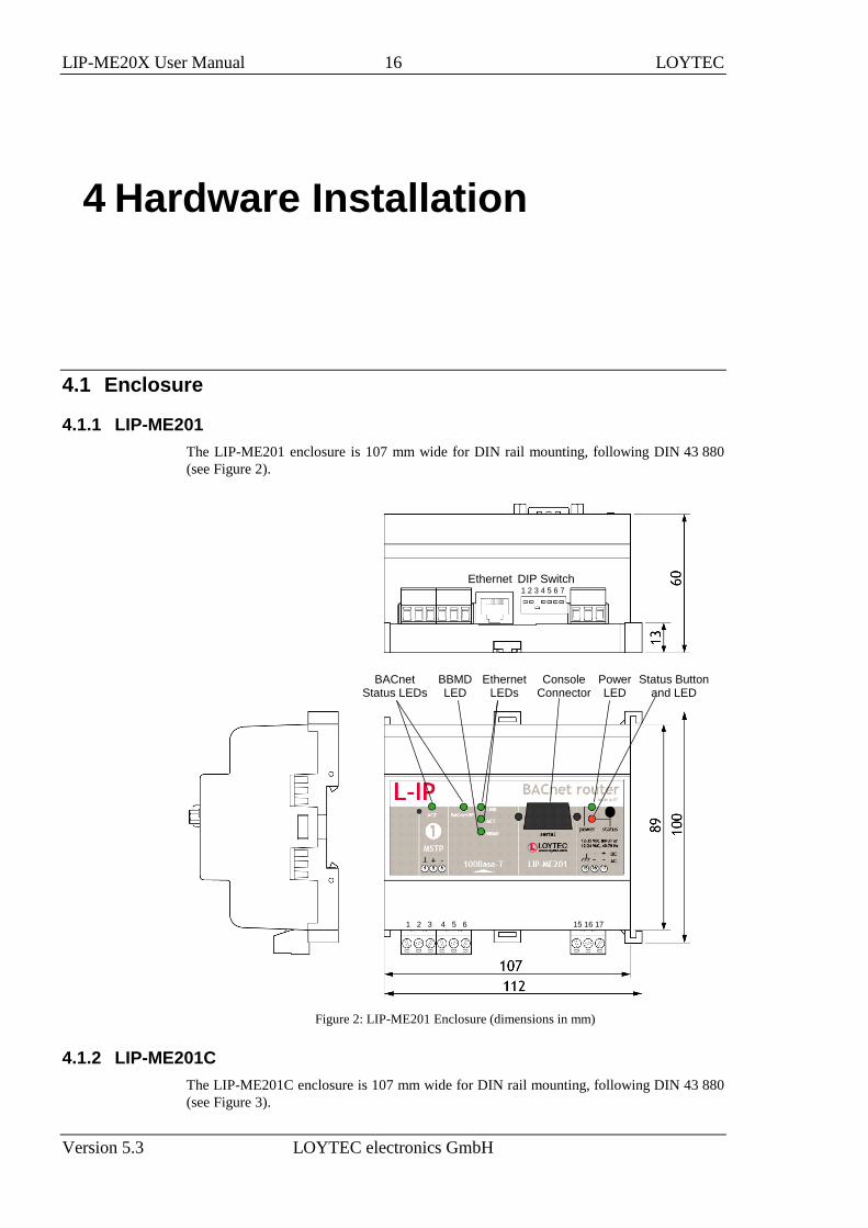
4.1.1 LIP-ME201
The LIP-ME201 enclosure is 107 mm wide for DIN rail mounting, following DIN 43 880
(see Figure 2).
1 2 3
Status Button and LED
1 2 3 4 5 6 7
DIP Switch
Console Connector
Power LED
BACnet Status LEDs
Ethernet
4 5 6 15 16 17
Ethernet LEDs
BBMD LED
Figure 2: LIP-ME201 Enclosure (dimensions in mm)
4.1.2 LIP-ME201C
The LIP-ME201C enclosure is 107 mm wide for DIN rail mounting, following DIN 43 880
(see Figure 3).

LIP-ME20X User Manual 17 LOYTEC
Version 5.3 LOYTEC electronics GmbH
MS/TP Port LEDs
Ethernet
Jog Dial
USB
Power USB MS/TP
Figure 3: LIP-ME201C Enclosure (dimensions in mm)
4.1.3 LIP-ME202C
The LIP-ME202C enclosure is 107 mm wide for DIN rail mounting, following DIN 43 880
(see Figure 4).

LIP-ME20X User Manual 18 LOYTEC
Version 5.3 LOYTEC electronics GmbH
MS/TP Port LEDs
Ethernet
Jog Dial
USB
Power USB MS/TP
Figure 4: LIP-ME202C Enclosure (dimensions in mm)

LIP-ME20X User Manual 19 LOYTEC
Version 5.3 LOYTEC electronics GmbH
4.1.4 LIP-ME204
The LIP-ME204 enclosure is 159 mm wide for DIN rail mounting, following DIN 43 880
(see Figure 5).
USB, SD Card
MS/TP Port LEDs
Ethernet
Ethernet LEDs
Jog Dial
USB
BBMD LED
Power
BACnet/IP LED
Figure 5: LIP-ME204 Enclosure (dimensions in mm).
4.2 Product Label
4.2.1 LIP-ME201
The product label on the side of the LIP-ME201 contains the following information (see
Figure 6):
LIP-ME201 order number and date code,
Serial Number with bar-code (SER#),
Ethernet MAC Address with bar-code (MAC1).
Figure 6: LIP-ME201 product label.

LIP-ME20X User Manual 20 LOYTEC
Version 5.3 LOYTEC electronics GmbH
Unless stated otherwise, all bar codes are encoded using “Code 128”. An additional label is
also supplied with the device for documentation purposes.
4.2.2 LIP-ME201C, LIP-ME202C
The product label on the side of the LIP-ME201C and LIP-ME202C contains the following
information (see Figure 7):
LIP-ME201C or LIP-ME202C order number and date code,
serial number with bar-code (Ser#),
Ethernet MAC ID with bar-code (MAC1).
Figure 7: LIP-ME201C, LIP-ME202C product label.
Unless stated otherwise, all bar codes are encoded using “Code 128”. An additional label is
also supplied with the device for documentation purposes.
4.2.3 LIP-ME204
The product label on the side of the LIP-ME204 contains the following information (see
Figure 8):
LIP-ME204 order number and date code,
serial number with bar-code (Ser#),
Ethernet MAC ID with bar-code (MAC1).
Figure 8: LIP-ME204 product label.

LIP-ME20X User Manual 21 LOYTEC
Version 5.3 LOYTEC electronics GmbH
Unless stated otherwise, all bar codes are encoded using “Code 128”. An additional label is
also supplied with the device for documentation purposes.
4.3 Mounting
The device comes prepared for mounting on DIN rails following DIN 50 022. The device
can be mounted in any position. However, an installation place with proper airflow must be
selected to ensure that the LIP-ME20X’s temperature does not exceed the specified range
(see Chapter 11).
4.4 LED signals
4.4.1 Power LED
The LIP-ME201 power LED lights up green when power is supplied to terminals 16 and 17.
4.4.2 Status LED
The LIP-ME201 is equipped with a red status LED (see Figure 2). This LED is normally
off.
If the fall-back image is executed, the status LED flashes red once every second.
4.4.3 MSTP Activity LED
The MS/TP port has a three-color MSTP Activity LED (see Figure 2). Table 2 shows the
different LED patterns of the port and their meaning. A permanent color reflects a state.
Flicker is for 25 ms when there is activity on the MS/TP data link layer.
Behavior Description Comment
GREEN permanently,
flicker off
Multi-Master, token ok, flicker when traffic Normal condition on a multi-master
MS/TP network.
ORANGE flicker Sole master, flicker when traffic Normal condition on a single-master
MS/TP network.
RED permanent, flicker
GREEN
Token lost state, flicker when transmit attempt Cable might be broken.
RED flash fast Transmission or receive errors This indicates bad cabling.
Table 2: MS/TP Activity LED Patterns
4.4.4 Ethernet Link LED
The Ethernet Link LED lights up green whenever an Ethernet cable is plugged-in and a
physical connection with a switch, hub, or PC can be established.
4.4.5 Ethernet Activity LED
The Ethernet Activity LED lights up green for 6 ms whenever a packet is transmitted or
received or when a collision is detected on the network cable.
4.4.6 BACnet/IP LED
The BACnet/IP LED flashes green for 25 ms when BACnet packets are transmitted or
received over the BACnet/IP interface.

LIP-ME20X User Manual 22 LOYTEC
Version 5.3 LOYTEC electronics GmbH
4.4.7 BBMD LED
The BBMD LED is permanent green if BBMD is enabled. Otherwise, it is off.
4.5 Status Button
The LIP-ME201 is equipped with a status button (see Figure 2). When pressing the status
button shortly during normal operation of the LIP-ME201, it sends a BACnet “I-Am”
message on all active BACnet data link layers.
The status button can also be used to switch the device back to factory default state. Press
the service button and power-cycle the device. Keep the button pressed until the port LEDs
illuminate orange permanently. Release the button within five seconds from that time on to
reset the device to factory defaults. Alternatively, the device can be switched back to factory
defaults over the console user interface (see Section 9.2.2).
4.6 LCD Display and Jog Dial
Device models with an LCD display can also be configured to their basic settings through
jog dial navigation on the LCD UI. The main page of the LCD UI is shown in Figure 9. It
displays the device’s IP address, hostname, CPU load, system temperature and supply
voltage.
Below are menu items. Turn the jog dial to navigate between menu items and press to enter
a menu or go into selection mode. When in selection mode turn the jog dial to alter the
value and press again to quit the selection. The Datapoints »» menu allows browsing
through the data points on the device.
Figure 9: Main Screen of the LCD UI.
The Device Settings »» menu allows configuring basic device settings. Navigate to the
Device Management »» sub-menu, which is displayed in Figure 10.
Figure 10: Device Management Menu on the LCD UI.
This menu gives you the following options for basic device configuration:
TCP/IP Setup: This menu allows configuring the device’s IP address.
HTTP Server: This menu allows to enable/disable the HTTP server and to configure
its TCP port.
HTTPS Server: This menu allows to enable/disable the HTTP server, to configure its
TCP port and to remove an installed certificate.

LIP-ME20X User Manual 23 LOYTEC
Version 5.3 LOYTEC electronics GmbH
Date/Time: This menu allows setting the system time. A time synchronization
mechanism can be chosen, and the UTC offset and daylight savings can be defined.
Send ID messages: When selecting this menu, the device sends out service pin,
BACnet I-Am, and identification broadcasts for finding the device in the L-Config tool
on all applicable ports.
Reload config: By choosing this menu, the device performs a quick restart by
reloading its configuration only.
Reboot system: By choosing this menu, the device performs a full reboot.
Factory Defaults: By choosing this menu, the user can reset the entire device to its
factory default. Also IP addresses are cleared.
Remote Config: When enabling this option, the LWEB-900 master device manager
restores the last saved configuration to the discovered device, if it has no configuration
yet. This feature is beneficial when replacing a device.
PIN: Alter the default PIN to any 4-digit number to protect certain operations on the
LCD UI. The user will be prompted to enter the PIN on protected areas.
Contrast: This menu allows adjusting the display’s contrast.
Language: By choosing this menu, the user can switch between languages on the LCD
display.
The Device Settings »» menu also allows configuring basic BACnet settings. Navigate to
the BACnet »» sub-menu, which is displayed in Figure 10.
Figure 11: BACnet Menu on the LCD UI.
This menu gives you the following options for basic BACnet configuration:
Send I-Am message: This menu allows sending an I-Am message to the BACnet
network.
ID: Use this menu to enter the BACnet device ID. Choose the first four digits then
move on the last three digits.
BAC/IP Net: On a BACnet router use this setting to specify the BACnet network
number on the BACnet/IP port.
MS/TP Net: On a BACnet router use this setting to specify the BACnet network
number on the MS/TP port. If the device has more than one MS/TP port this menu is
available for each MS/TP port. To disable the router port, scroll down till off appears.
4.7 DIP Switch Settings
The DIP switch assignment for the LIP-ME201 is shown in Table 3. Please leave all
switches at default state.

LIP-ME20X User Manual 24 LOYTEC
Version 5.3 LOYTEC electronics GmbH
DIP Switch # Function Factory Default
1 Must be OFF OFF
2 Must be OFF OFF
3 Must be ON ON
4 Must be OFF OFF
5 Must be OFF OFF
6 Must be OFF OFF
7 Must be OFF OFF
Table 3: DIP Switch Settings for LIP-ME201
4.8 Terminal Layout and Power Supply
4.8.1 LIP-ME201
The LIP-ME201 provides screw terminals to connect to the network as well as to the power
supply. The screw terminals can be used for wires of a maximum thickness of 1.5
mm2/AWG12. The device can either be DC or AC powered.
Terminal Function
4 BACnet MS/TP Ground
5 BACnet MS/TP Non-Inverting Input
6 BACnet MS/TP Inverting Input
8 Ethernet 100BaseT
15 Earth Ground
16, 17 Power Supply 12-35 VDC or 12-24 VAC ± 10%
Do not connect terminal 17 to earth ground!
Table 4: LIP-ME201 Terminals
4.9 Wiring
4.9.1 LIP-ME201
If BACnet over MS/TP is enabled, the MS/TP network segment must be properly
terminated with an LT-04 network terminator connected at each of the two ends of the
segment media.
Important: When using 2-wire MS/TP, earth ground must be connected to both terminal 15 and 16
(see Figure 12a). Never connect terminal 17 to earth ground!

LIP-ME20X User Manual 25 LOYTEC
Version 5.3 LOYTEC electronics GmbH
2-wire
MS/TP
Power Supply
Ethernet
Ethernet
Power Supply 3-wire
MS/TP
(a) (b)
Figure 12: Connecting the LIP-ME201: (a) 2-wire MS/TP, (b) 3-wire MS/TP
4.9.2 LIP-ME201C, LIP-ME202C
The terminals and wiring information for the LIP-ME201C and LIP-ME202C can be seen
in Figure 13. The MS/TP network segments must be properly terminated with an LT-04
network terminator connected at each of the two ends of the segment media.

LIP-ME20X User Manual 26 LOYTEC
Version 5.3 LOYTEC electronics GmbH
Figure 13: Connecting the LIP-ME201C, LIP-ME202C.
4.9.3 LIP-ME204
The terminals and wiring information for the LIP-ME204 can be seen in Figure 14. The
MS/TP network segments must be properly terminated with an LT-04 network terminator
connected at each of the two ends of the segment media.

LIP-ME20X User Manual 27 LOYTEC
Version 5.3 LOYTEC electronics GmbH
Figure 14: Connecting the LIP-ME204.

LIP-ME20X User Manual 28 LOYTEC
Version 5.3 LOYTEC electronics GmbH
5 Web Interface
The LIP-ME20X comes with a built-in Web server and a Web interface to configure the
LIP-ME20X and extract statistics information. The Web interface allows configuring the IP
settings, BACnet and other configuration settings.
5.1 Device Information and Account Management
In a Web browser, enter the default IP address 192.168.1.254 of the LIP-ME20X. Note that
if your PC has an IP address in a subnet other than 192.168.1.xxx, you must open a
command tool and enter the following route command to add a route to device.
To Add a Route to the Device
1. Windows START Run
2. Enter ‘cmd’ and click OK.
3. In the command window enter the command line
route add 192.168.1.254 %COMPUTERNAME%
In Windows7 replace %COMPUTERNAME% with the PC’s actual IP address.
4. Then open your Web browser and type in the default IP address ‘192.168.1.254’.
5. The device information page should appear as shown in Figure 15.
LIP-ME20X User Manual 29 LOYTEC
Version 5.3 LOYTEC electronics GmbH
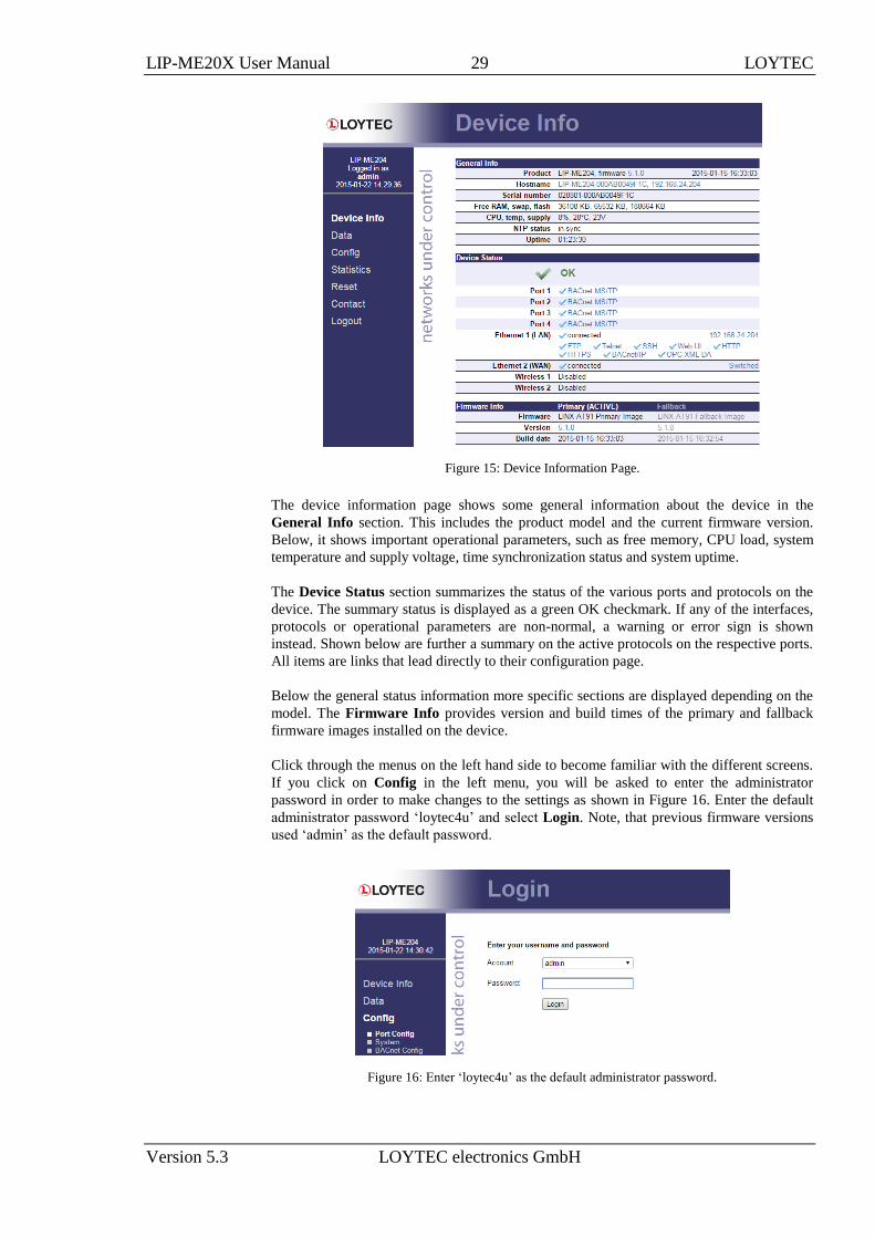
Figure 15: Device Information Page.
The device information page shows some general information about the device in the
General Info section. This includes the product model and the current firmware version.
Below, it shows important operational parameters, such as free memory, CPU load, system
temperature and supply voltage, time synchronization status and system uptime.
The Device Status section summarizes the status of the various ports and protocols on the
device. The summary status is displayed as a green OK checkmark. If any of the interfaces,
protocols or operational parameters are non-normal, a warning or error sign is shown
instead. Shown below are further a summary on the active protocols on the respective ports.
All items are links that lead directly to their configuration page.
Below the general status information more specific sections are displayed depending on the
model. The Firmware Info provides version and build times of the primary and fallback
firmware images installed on the device.
Click through the menus on the left hand side to become familiar with the different screens.
If you click on Config in the left menu, you will be asked to enter the administrator
password in order to make changes to the settings as shown in Figure 16. Enter the default
administrator password ‘loytec4u’ and select Login. Note, that previous firmware versions
used ‘admin’ as the default password.
Figure 16: Enter ‘loytec4u’ as the default administrator password.

LIP-ME20X User Manual 30 LOYTEC
Version 5.3 LOYTEC electronics GmbH
The Config menu opens. Click on Passwords in the Config menu, which opens the
password configuration page as shown in Figure 17. The device has three user accounts: (1)
guest allows the user to view certain information only, e.g., the device info page. By default
the guest user has no password. (2) operator is able to read more sensible information such
as calendar data. (3) admin has full access to the device and can make changes to its
configuration. Note that the user accounts are also used to log on to the FTP and Telnet
server.
Figure 17: Password Configuration Screen.
Please change the administrator password in order to protect yourself from unwanted
configuration changes by anyone else. To do so, select the admin account in the drop-down
box and enter the new password. If the administrator password is left empty, password
protection is turned off and everyone can access the LIP-ME20X without entering a
password. Click on Change password to activate the change.
5.2 Device Configuration
The device configuration pages allow viewing and changing the device settings of the LIP-
ME20X. Here are some general rules for setting IP addresses, port numbers, and time
values:
An empty IP address field disables the entry.
An empty port number field sets the default port number.
An empty time value field disables the time setting.
5.2.1 System Configuration
The system configuration page is shown in Figure 18. This page allows configuring the
device’s system time and other system settings. The TCP/IP Configuration link is a
shortcut to the Ethernet port configuration. Follow that link to change the IP settings of the
device.
The time sync source can be set to auto, manual, NTP, BACnet. In the auto mode, the
device switches to the first external time source that is discovered. Possible external time
sources are NTP, BACnet. The option manual allows setting the time manually in the fields
Local Time and Local Date. In manual mode, the device does not switch to an external
time source. Note, that if NTP is selected, the NTP servers have to be configured on the IP
Configuration page (see Section 5.2.4).
The time zone offset must be defined independently of the time source. It is specified as the
offset to GMT in hours and minutes (e.g., Vienna/Austria is +01:00, New York/USA is
-06:00). For setting the daylight saving time (DST) predefined choices are offered for
Europe and USA/Canada. DST can be switched off completely by choosing none or set

LIP-ME20X User Manual 31 LOYTEC
Version 5.3 LOYTEC electronics GmbH
manually for other regions. In that case, start and end date of DST must be entered in the
fields below.
Figure 18: System Configuration Page, e.g., for Vienna, Austria.
The next section on the page allows to configure the device’s earth position. This setting
defines the longitude, latitude and elevation of the device. The latitude and longitude are
entered as degrees, minutes, and seconds. The altitude is entered in meters height above sea
level. This setting is used for an astronomical clock. For fixed locations such as a building,
the position can be entered on this page.
The CSV delimiter setting can be ignored on the LIP-ME20X.
5.2.2 Backup and Restore
A configuration backup of the LIP-ME20X device can be downloaded via the Web
interface. Click the backup link as shown in Figure 19 to start the download. The device
assembles a single file including all required files. A file requestor dialog allows specifying
the location where the backup file shall be stored.
To restore the device settings, simply select a previously generated backup file in the
Restore Configuration section of the page by clicking the button next to the Filename
field. Then press the Restore button.
The backed up configuration data consists of:
Device settings (Passwords, IP settings, BDT, ACL, etc.),

LIP-ME20X User Manual 32 LOYTEC
Version 5.3 LOYTEC electronics GmbH
Figure 19: Backup/Restore page.
5.2.3 Port Configuration
This menu allows configuring the device’s communications ports. For each communication
port, which is available on the device and shown on the label (e.g., Port 1, Port 2, Ethernet),
a corresponding configuration tab is provided by the Web UI. An example is shown in
Figure 20. Each port tab contains a selection of available communication protocols. By
selecting a checkbox or radio button the various protocols can be enabled or disabled on the
communication port. Some ports allow exclusive protocol activation only, other ports (e.g.,
the Ethernet port) allow multiple protocols bound to that port.
Figure 20: Port Configuration Page.
When selecting a protocol on a communication port, the protocol’s communication
parameters are displayed in a box on the right-hand side. To save the settings of the
currently opened protocol, click the Save Settings button. Pressing Get Settings retrieves
the current settings from the device.
5.2.4 IP Configuration
The TCP/IP configuration is done under the Ethernet port tab as shown in Figure 21. The
mandatory IP settings, which are needed to operate the device, are marked with a red
asterisk (IP address, netmask, gateway). The Enable DHCP checkbox switches between
manual entry of the IP address, netmask, and gateway address, and automatic configuration
from a DHCP server.

LIP-ME20X User Manual 33 LOYTEC
Version 5.3 LOYTEC electronics GmbH
Hostname and Domainname are optional entries and can be left empty. For some DHCP
configurations it may be necessary to enter a hostname. Please contact your system
administrator on how to configure DHCP to acquire an IP address. Further, you can
configure up to 3 Domain Name Servers. Currently these entries are not used.
Figure 21: IP Configuration Page.
The device comes configured with a unique MAC address. This address can be changed in
order to clone the MAC address of another device. Please contact your system administrator
to avoid MAC address conflicts.
If the device is operated with a 10 Mbit/s-only hub, the link speed should be switched from
Auto Detect to 10Mbps/Half-Duplex. With modern 100/10 Mbit/s switches, this setting
can be left at its default.
The settings for DNS and NTP servers should be made in the IP host settings (see Section
5.2.6). In case an IP interface runs DHCP, the DNS and NTP addresses supplied by DHCP
can be seen here. Models with one Ethernet port only do not have these settings here.
Other standard protocols that are bound to the Ethernet interface are FTP, Telnet, and
HTTP (Web server). By deselecting the checkbox, those protocols can be individually
disabled. The standard UDP/TCP ports can be changed in the respective protocol settings.
An example for the FTP server is shown for FTP in Figure 22. The FTP server is used for
instance to update the firmware (see Section 8.1). Note that HTTP for the Web server can
only be disabled on the console interface or by using the LCD display.
Figure 22: FTP server configuration on the Ethernet port.

LIP-ME20X User Manual 34 LOYTEC
Version 5.3 LOYTEC electronics GmbH
5.2.5 Using Multiple IP Ports
On models with multiple IP interfaces, the port configuration provides a separate port tab
for each IP port, e.g., Ethernet 1 (LAN) and Ethernet 2 (WAN). In the port mode setting
these interfaces can be enabled to operate as a separate IP network. As a default only
Ethernet 1 (LAN) is enabled and configured to be switched with the Ethernet 2 port. To
enable Ethernet 2 (WAN) as a separate, isolated IP network, choose Separate network in
the port mode setting as shown in Figure 23 and save settings. A reboot is required to make
this change effective.
For each IP interface configured as a separate network, the various standard protocols can
be enabled separately. As a default, the secure protocols HTTPS, SSH and OPC UA are
enabled on a new separate IP interface. Some protocols can be enabled on multiple
interfaces at the same time, others on one interface only. If one of the latter is enabled on a
new separate IP interface, a warning will be displayed, stating on which other interface the
protocol will now be disabled (e.g., BACnet/IP).
The separate network mode can be used, if you want to operate an isolated building network
on the LAN and expose some aspects outside the building network (denoted as WAN).
Physically, the two Ethernet ports will be plugged into different Ethernet switches.
Figure 23: Enable the Ethernet 2 (WAN) interface.
To disable a separate IP interface, choose Disable in the port mode setting. This change is
effective immediately without a reboot. To configure switch mode again, choose Switch
Ethernet 1+2 in the port mode setting.
5.2.6 IP Host Configuration
The LIP-ME20X models, which provide a built-in Ethernet switch/hub possess a separate
IP Host tab for editing all common host settings as shown in Figure 24. These settings
affect all IP interfaces on the entire device. On models with a single Ethernet port, the IP
Host settings appear directly on the Ethernet tab.
Hostname and Domainname are optional entries and can be left empty. For some DHCP
configurations it may be necessary to enter a hostname. Please contact your system
administrator on how to configure DHCP to acquire an IP address.
The Default Gateway setting defines the gateway of a given IP interface, which is going to
route all non-local network traffic. One of the existing IP interfaces with a separate network
must be selected here.
Up to three DNS Servers can be defined on this page. These DNS servers will be contacted
by all services on any of the IP interfaces for name resolution. In case the DNS servers are
supplied by DHCP running one of the IP interfaces, change the setting Use DNS servers
from to point to that interface.

LIP-ME20X User Manual 35 LOYTEC
Version 5.3 LOYTEC electronics GmbH
Figure 24: Setting on the IP Host tab.
The device can be configured to synchronize its clock with NTP time. Enter the IP address
of a primary and, optionally, a secondary NTP server. The device will use NTP as a time
source if the time sync source in the system configuration page is set to NTP (see Section
5.2.1). The field NTP status below the NTP server settings displays the current NTP
synchronization status (out-of-sync, or in-sync). The settings made here apply to all IP
interfaces. In case the NTP servers are supplied by DHCP running one of the IP interfaces,
change the setting Use NTP servers from to point to that interface.
The Connection Keep Alive feature allows the device to automatically ping other devices
on the IP network in order to maintain an IP connection that might be automatically
disconnected after a specific period of time (e.g. DSL routers automatically disconnect if no
activity is detected). When enabled choose one of the options Auto IP or Custom IP.
If auto IP mode is selected and the device has a CEA-852 configuration server, a ping
message is sent to all CEA-852 devices in the channel list of the configuration server. If the
configuration server is disabled on this device a ping message is sent to the configuration
server for the IP-852 channel, if one is known. If custom IP is selected, one specific IP
address can be configured as the ping destination.
5.2.7 WLAN Configuration
Devices supporting the LWLAN-800 wireless adapter can be connected to IEEE 802.11
wireless networks. The basic functions available in WLAN operation are described in
Section 7.3. Depending on the required wireless modes, the first configuration step is to
select the port mode on the Wireless tab of the port configuration, as shown in Figure 25.
Figure 25: Wireless Port Mode
The following port modes can be selected:
Disable: The wireless interface is disabled.

LIP-ME20X User Manual 36 LOYTEC
Version 5.3 LOYTEC electronics GmbH
Separate network: The wireless interface is enabled, but not bridged to any
Ethernet interface. It provides its own, isolated services.
Bridge to Ethernet 1: The wireless interface is enabled and bridged to the
Ethernet 1 interface.
Bridge to Ethernet 2: The wireless interface is enabled and bridged to the
Ethernet 2 interface.
After having selected the port mode, the IP settings have to be set, if the wireless port is
configured as a separate network. The wireless interfaces are configured in the same way as
Ethernet interfaces described in Section 5.2.5. Depending on the wireless mode, there are
some differences:
Access point mode (separate network): The IP address and netmask are used to
define the network in which client get an IP address from the built-in DHCP
server. DNS and NTP settings are not needed in this mode.
The wireless client settings are made in the Wireless protocol area. This allows setting the
WIRELESS mode in a drop-down box. The following basic modes are available, which are
described below in more detail:
Client Mode: The WLAN client connects to an existing access point.
Access Point Mode: The device provides a WLAN access point where a client can
connect to the wireless network created by the device.
Mesh Mode: This mode is used to create an IEEE 802.11s mesh network.
Client Mode. A wireless interface in client mode has the settings shown in Figure 26.
Figure 26: WLAN Client Settings

LIP-ME20X User Manual 37 LOYTEC
Version 5.3 LOYTEC electronics GmbH
The following settings are used to configure the wireless client mode:
SSID: This is the service set ID identifying the wireless network to connect to. It
can be entered manually, e.g. if the network is hidden, or scanned using the scan
button. Note that scanning interrupts an active wireless connection, so use this
button only when setting up the wireless connection.
Search Results: The search results list contains the discovered SSIDs and signal
strenghts. Selecting one of the items copies it into the SSID field.
Key Management: This list selects between NONE (no encryption), WEP, WPA
and WPA2 encryption. The recommended setting is WPA2, as WPA and WEP are
not considered secure anymore and are provided for backwards compatibility.
Pre-Shared Key: The preshared key is the encryption key for the wireless
network. The show checkbox shows the PSK in clear text.
Verbose Logging: In case of connection problems, this checkbox can be activated
to store wireless connection information in the OS log. It is not recommended to
leave this option activated during normal operation.
The page displays the following information:
Wireless-USB-Adapter: The type of the connected wireless adapter.
WLAN Client: Displays whether the interface is connected to a wireless network.
WLAN Client Signal: Displays the signal strenght.
WLAN MAC-Address: Displays the MAC address of the wireless adapter
Access Point Mode. An access point has the settings shown in Figure 27.
Figure 27: WLAN Access Point Settings

LIP-ME20X User Manual 38 LOYTEC
Version 5.3 LOYTEC electronics GmbH
The following settings are used to configure the access point mode:
SSID: This is the service set ID identifying the wireless network provided by this
access point. The hide SSID checkbox hides the SSID, so that it cannot be
scanned. Not that hiding an SSID has more security drawbacks than advantages, so
that this setting should be left deactivated.
Region: This defines the region, Europe, North America or Japan, in which this
access point is deployed. Note that this settings has to be made correctly to comply
with regulatory restrictions. Incorrect settings may cause interference.
Channel: This field selects an available channel. The 2.4 GHz Band provides 13
channels. However these channels overlap and cannot be used without
interference. When possible, use channels 1, 6 or 11 to avoid overlapping
networks.
802.11 Protocol: This field selects the wireless protocol to use. The default and
recommended setting is 802.11b/g/n, which provides all protocols. If there are
compatibility issues with some clients, the access point can be restricted to
802.11b/g or 802.11b.
Key Management: This list selects between NONE (no encryption), WEP, WPA
and WPA2 encryption. The recommended setting is WPA2, as WPA and WEP are
not considered secure anymore and are provided for backwards compatibility.
Encryption Type: This list selects between different encryption options, e.g. AES
or TKIP.
Pre-Shared Key: The preshared key is the encryption key for the wireless
network. The show checkbox shows the PSK in clear text. For a secure network,
please use WPA2, AES encryption and a PSK with at least 16 characters.
Verbose Logging: In case of connection problems, this checkbox can be activated
to store wireless connection information in the OS log. It is not recommended to
leave this option activated during normal operation.
The page displays the following information:
Wireless-USB-Adapter: The type of the connected wireless adapter.
WLAN Access-Point: Displays status of the access point.
WLAN MAC-Address: Displays the MAC address of the wireless adapter.
Mesh Mode. A mesh point or mesh portal has the settings shown in Figure 28.

LIP-ME20X User Manual 39 LOYTEC
Version 5.3 LOYTEC electronics GmbH
Figure 28: WLAN Mesh Network Settings
The following settings are used to configure the wireless client mode:
MeshID: This is the service set ID identifying the wireless network to connect to.
It can be entered manually, e.g. if the network is hidden, or scanned using the scan
button. Note that scanning interrupts an active wireless connection, so use this
button only when setting up the wireless connection.
Search Results: The search results list contains the discovered SSIDs and signal
strenghts. Selecting one of the items copies it into the SSID field.
Region: This defines the region, Europe, North America or Japan, in which this
access point is deployed. Note that this settings has to be made correctly to comply
with regulatory restrictions. Incorrect settings may cause interference.
Channel: This field selects an available channel. The 2.4 GHz Band provides 13
channels. However these channels overlap and cannot be used without
interference. When possible, use channels 1, 6 or 11 to avoid overlapping
networks. All members of a mesh network have to use the same channel.
802.11 Protocol: This field selects the wireless protocol to use. The default and
recommended setting is 802.11b/g/n, which provides all protocols. If there are
compatibility issues with some clients, the access point can be restricted to
802.11b/g or 802.11b.
Pre-Shared Key: The preshared key is the encryption key for the wireless
network. The show checkbox shows the PSK in clear text. A mesh network should
be protected by a Mesh ID of at least 16 random characters.
The page displays the following information:

LIP-ME20X User Manual 40 LOYTEC
Version 5.3 LOYTEC electronics GmbH
Wireless-USB-Adapter: The type of the connected wireless adapter.
MESH Point: Displays whether the interface is connected to a mesh network..
MESH Point Signal: Displays the signal strenght.
MESH Portal: Indicates whether this is a mesh point or portal.
WLAN MAC-Address: Displays the MAC address of the wireless adapter.
The buttons in the bottom area allow to export and import the wireless configuration. This
allows to configure a device and to easily transfer the wireless settings to other devices. The
Export button allows to save a file containing the wireless settings. The Import button
imports a wireless configuration which has been selected by the Browse button. After
changing the wireless settings, you need to click on Save Settings and reset the device for
applying the settings.
5.2.8 BACnet Device Configuration
Figure 29 shows the BACnet device configuration page. This configuration page allows
setting the Device ID, which is the instance part of the Object_Identifier property of the
BACnet Device object. The field Device name holds the name of the BACnet device object
(property Object_Name).
Important: The device ID and device name must be unique within the BACnet internetwork.
Figure 29: BACnet Device Configuration.
Further, the description and location can be configured. These configuration items
correspond to the properties Description, and Location respectively of the BACnet Device
object. For tuning BACnet application timing parameters, set APDU timeout, APDU
segment timeout, and APDU retry count. The timeout values are entered in seconds
allowing decimal notation, e.g. "7.5".
On the settings for BACnet/IP refer to Section 5.2.9. For configuring the MS/TP data link
refer to Section 5.2.10.
Note: If this page displays the message "Device communication is disabled via BACnet network!"
the device has been externally disabled. Reboot the device to activate communication
again.
LIP-ME20X User Manual 41 LOYTEC
Version 5.3 LOYTEC electronics GmbH
5.2.9 BACnet/IP Configuration
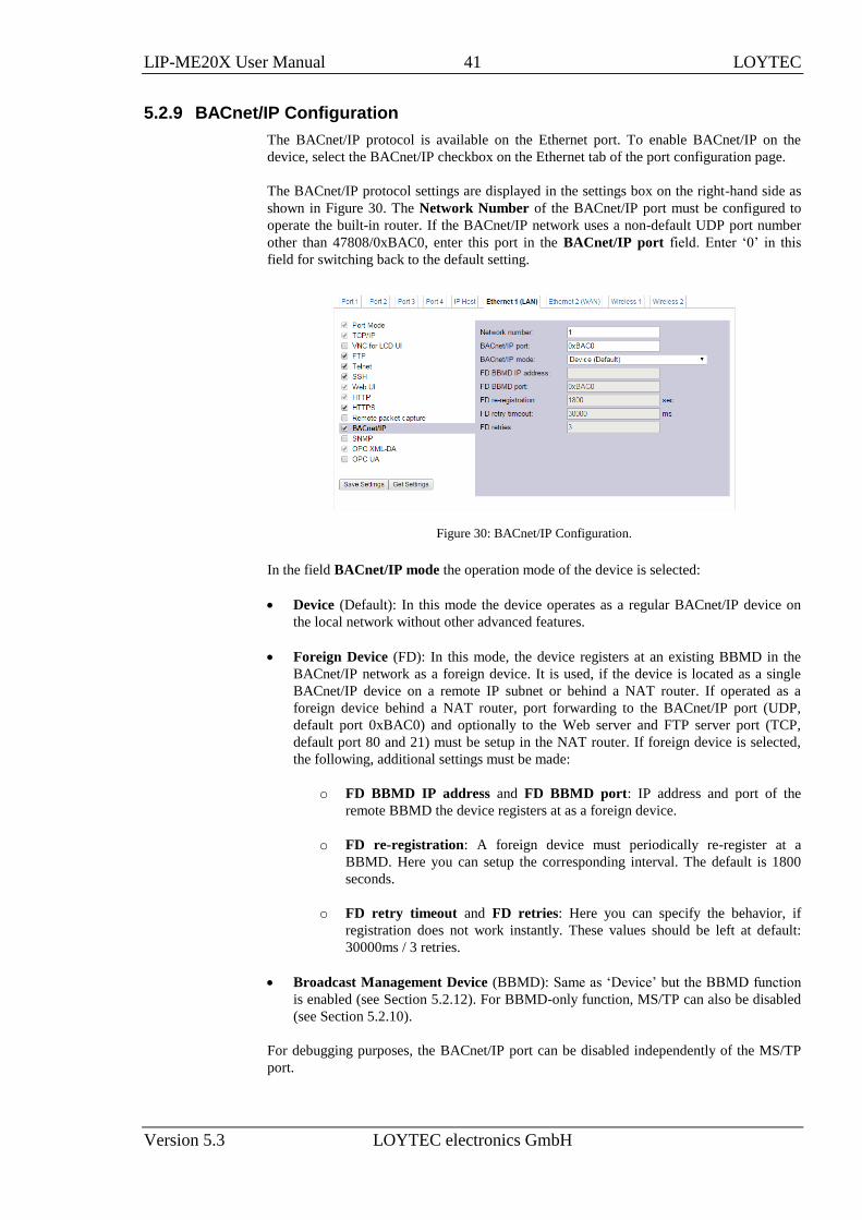
The BACnet/IP protocol is available on the Ethernet port. To enable BACnet/IP on the
device, select the BACnet/IP checkbox on the Ethernet tab of the port configuration page.
The BACnet/IP protocol settings are displayed in the settings box on the right-hand side as
shown in Figure 30. The Network Number of the BACnet/IP port must be configured to
operate the built-in router. If the BACnet/IP network uses a non-default UDP port number
other than 47808/0xBAC0, enter this port in the BACnet/IP port field. Enter ‘0’ in this
field for switching back to the default setting.
Figure 30: BACnet/IP Configuration.
In the field BACnet/IP mode the operation mode of the device is selected:
Device (Default): In this mode the device operates as a regular BACnet/IP device on
the local network without other advanced features.
Foreign Device (FD): In this mode, the device registers at an existing BBMD in the
BACnet/IP network as a foreign device. It is used, if the device is located as a single
BACnet/IP device on a remote IP subnet or behind a NAT router. If operated as a
foreign device behind a NAT router, port forwarding to the BACnet/IP port (UDP,
default port 0xBAC0) and optionally to the Web server and FTP server port (TCP,
default port 80 and 21) must be setup in the NAT router. If foreign device is selected,
the following, additional settings must be made:
o FD BBMD IP address and FD BBMD port: IP address and port of the
remote BBMD the device registers at as a foreign device.
o FD re-registration: A foreign device must periodically re-register at a
BBMD. Here you can setup the corresponding interval. The default is 1800
seconds.
o FD retry timeout and FD retries: Here you can specify the behavior, if
registration does not work instantly. These values should be left at default:
30000ms / 3 retries.
Broadcast Management Device (BBMD): Same as ‘Device’ but the BBMD function
is enabled (see Section 5.2.12). For BBMD-only function, MS/TP can also be disabled
(see Section 5.2.10).
For debugging purposes, the BACnet/IP port can be disabled independently of the MS/TP
port.

LIP-ME20X User Manual 42 LOYTEC
Version 5.3 LOYTEC electronics GmbH
5.2.10 MS/TP Configuration
The BACnet MS/TP protocol can be enabled on the device’s port Port1. To enable it, click
the BACnet MS/TP radio button as shown in Figure 31. The MS/TP port on the LIP-
ME20X is enabled by default.
Figure 31: MS/TP Configuration.
The MS/TP protocol settings are displayed in the settings box on the right-hand side as
shown in Figure 31. Mandatory settings are the MS/TP node number and the MS/TP
baud rate. The MS/TP node number determines the physical address of the device on the
MS/TP channel and must be in the range from ‘0’ to the number configured with the
MS/TP max master configuration option. It must be unique within the MS/TP channel.
The latter parameter defines the maximal number of MS/TP master devices on the MS/TP
channel. The Baud rate on the MS/TP channel can be set to 9600, 19200, 38400, and 76800
Baud.
Important: All masters on the MS/TP channel must have the same setting for MS/TP max master.
Decreasing the default value 127 of MS/TP max master may reduce latency on the
MS/TP bus.
It is strongly recommended to leave the MS/TP max info frames and the MS/TP max
master configuration options at their default settings. In any case the MS/TP max master
number must be high enough to include the highest MS/TP node number of all masters on
the channel. Slave devices may have a higher MS/TP node number than MS/TP max
master.
To operate with slow devices on the MS/TP network set the Network Timing option to
slow. This increases a number of timeouts, which is needed by some devices, but slows
down network communication. If communication problems occur in standard mode, try
setting the slow mode. For fine-tuning other parameters please refer to Section 7.1.
The Network Number of the MS/TP port must be set to a non-zero value in order to
operate the build-in BACnet/IP-BACnet MS/TP router.
5.2.11 BACnet Time Master
The BACnet time master function relies on a list of time recipients. The Time Master tab
of the BACnet Config Web page (see Figure 32) allows adding and removing time
recipients of two classes: UTC time sync recipients, and time sync recipients (receiving
local time). The time sync interval can also be configured on this tab. See Section 6.1.8 for
more information on the settings for time sync interval, interval offset and align intervals.

LIP-ME20X User Manual 43 LOYTEC
Version 5.3 LOYTEC electronics GmbH
Figure 32: BACnet Time Master Configuration.
5.2.12 BACnet BDT (Broadcast Distribution Table)
The BBMD function is needed when a BACnet/IP network spans over several IP subnets
separated by IP routers. If the device is configured as a BBMD, i.e. the BACnet/IP mode is
set to Broadcast Management Device, see Section 5.2.9, the BDT (Broadcast Distribution
Table) specifies all other BBMDs of the BACnet/IP network. The BDT is shown in Figure
33.
Figure 33: BACnet Broadcast Distribution Table.
By clicking Add Device new BBMDs (IP address and port) can be added. With Action on
Selected and selecting existing entries, certain BBMDs can be deleted again from the table.
It is not necessary to reboot the device when changing the table. However, you may want to
click Distribute in order to propagate the table to all BBMDs in the list.
Note: The recommended maximum are 100 BBMD entries in the BDT.
In the Global Settings section of this configuration page the behavior of the BDT can be
modified:
Write-protect BDT from network: If this option is enabled, the BBMD will reject
any Write-BDT requests from the BACnet network. This option may be useful to
protect your BDT tables from malicious access from the network.

LIP-ME20X User Manual 44 LOYTEC
Version 5.3 LOYTEC electronics GmbH
Enable 1-hop mode: Normally, the BBMD forwards broadcasts to the designated IP
addresses of other BBMDs. This mode is called 2-hop mode. If the IP infrastructure
allows sending directed broadcasts to other subnets, the BBMD can be switched to 1-
hop mode. In this case, the subnet masks of the destination networks must be
configured in the BDT entries.
5.2.13 BACnet ACL (Access Control List)
The device provides a feature in BACnet/IP to filter packets from certain sources on the
BACnet/IP network. This feature is based on an access control list (ACL). An example of
the ACL configuration is shown in Figure 34.
Figure 34: BACnet Access Control List (ACL).
The user can add and delete entries to the ACL. Each entry contains a source specification,
which consists of an IP address and an IP mask, and an action (allow or deny). For
specifying single hosts use the IP address and the mask '255.255.255.255'. For an address
range specify an appropriate mask. For example use '10.101.17.0' and the mask
'255.255.255.0' to specify all hosts with IP addresses '10.101.17.xxx'. To specify all IP
addresses use '0.0.0.0' and the mask '0.0.0.0'.
The ACL is evaluated from specific host entries down to wider ranges. When adding new
entries the ACL is automatically sorted, having the most precise definition at the top and the
most general one at the bottom. The default behavior is to allow packets from all IP
addresses. This is also the default entry in the ACL.
The example shown in Figure 34 specifies the following behavior for BACnet/IP:
1. Allow packets from the device 192.168.1.64
2. Otherwise allow packets from devices in the network 10.101.17.xxx
3. Otherwise deny packets from all (other) IP addresses. Note, that a rule for "deny"
overrules an equal rule for "allow".
5.2.14 BACnet Slave Proxy
The device provides an MS/TP slave proxy function. It can be enabled in the MS/TP port
configuration settings (see Section 5.2.10). In auto-discovery mode the slave proxy
permanently scans the MS/TP channel and automatically detects MS/TP slave devices. On
the Slave Proxy tab of the BACnet Config page the Slave Address Bindings list shows all
detected slave devices and displays their device instance number and BACnet address
(DNET:MAC address) information as shown in Figure 35.
It is also possible to manually add slave address bindings in case MS/TP devices are not
detected automatically. For doing so click the Add button and enter the device instance
number and BACnet address. If not known, leave the DNET part empty and press Enter.

LIP-ME20X User Manual 45 LOYTEC
Version 5.3 LOYTEC electronics GmbH
After adding all manual entries select the Update DNET check box and click on Save
Settings. This updates the current MS/TP DNET number for the manual slave address
bindings.
Figure 35: BACnet MS/TP slave proxy address bindings.
5.2.15 Firmware
The firmware page allows upgrading the device’s firmware over the Web interface. It offers
two options:
Web Update: With Web update the device searches for the latest available firmware
on the LOYTEC server. Click on the refresh symbol, if no latest version is displayed.
Please note, that the device must have a DNS server configured to find the LOYTEC
server. Click on the Install button to upgrade your device.
Local file: Update the device from a local disk file. For doing so, choose a .dl file on
you hard drive and then click on the Start Update button.
Figure 36: Firmware upgrade over the Web interface.
5.2.16 SNMP
The device has a built-in SNMP server. All system registers and OPC-exposed data points
are available as variables in the SNMP management information base (MIB). The MIB
definition can be downloaded from the Web interface as shown in Figure 37. One can
choose between a text and an XML format, depending on the SNMP tool in use. For more
information on SNMP on the device please refer to Section 6.2.

LIP-ME20X User Manual 46 LOYTEC
Version 5.3 LOYTEC electronics GmbH
Figure 37: Get the SNMP MIB from the Web interface
5.2.17 Documentation
The Documentation page in the Config menu allows uploading documentation files or
configuring links to external documentation (e.g. Wiring plans, etc.). The documentation
configured on this page is accessible via the Documentation menu (see Section 5.4).
Figure 38: Upload and configure documentation.
To upload a documentation file click on the Choose File button. This opens a file dialog.
Chose the file to upload. Click on the Upload button to start the upload of the selected file.
After the upload is completed the file appears in the Documentation files section. Enter a
link text used to display the uploaded file on the Documentation page.
To add a documentation link, click on the symbol in the header row of the
Documentation links section. Enter the URL and the text used to display the link on the
Documentation page.
Links and files can be set active and inactive on the Documentation page by checking the
Enabled check box. Inactive entries are not displayed on the Documentation page. The
check box New window determines if the link or file is opened in a new browser tab. If
Show in browser is checked the browser will try to render the file in the browser, otherwise
it will try to download the file. To remove a link or file click on the symbol on the right
side of the row. To commit your changes click on the Save button.
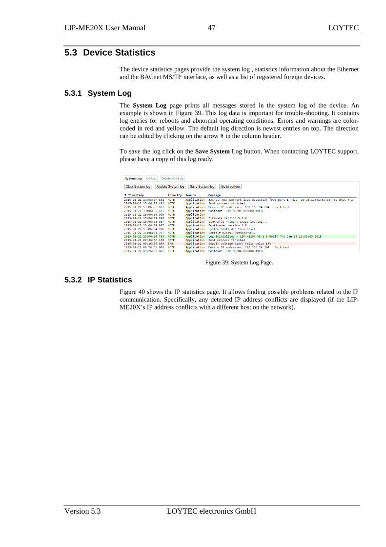
LIP-ME20X User Manual 47 LOYTEC
Version 5.3 LOYTEC electronics GmbH
5.3 Device Statistics
The device statistics pages provide the system log , statistics information about the Ethernet
and the BACnet MS/TP interface, as well as a list of registered foreign devices.
5.3.1 System Log
The System Log page prints all messages stored in the system log of the device. An
example is shown in Figure 39. This log data is important for trouble-shooting. It contains
log entries for reboots and abnormal operating conditions. Errors and warnings are color-
coded in red and yellow. The default log direction is newest entries on top. The direction
can be edited by clicking on the arrow in the column header.
To save the log click on the Save System Log button. When contacting LOYTEC support,
please have a copy of this log ready.
Figure 39: System Log Page.
5.3.2 IP Statistics
Figure 40 shows the IP statistics page. It allows finding possible problems related to the IP
communication. Specifically, any detected IP address conflicts are displayed (if the LIP-
ME20X’s IP address conflicts with a different host on the network).
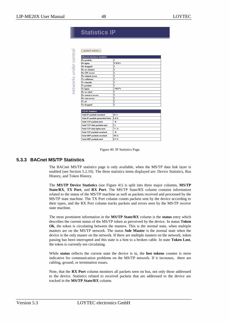
LIP-ME20X User Manual 48 LOYTEC
Version 5.3 LOYTEC electronics GmbH
Figure 40: IP Statistics Page.
5.3.3 BACnet MS/TP Statistics
The BACnet MS/TP statistics page is only available, when the MS/TP data link layer is
enabled (see Section 5.2.10). The three statistics items displayed are: Device Statistics, Bus
History, and Token History.
The MS/TP Device Statistics (see Figure 41) is split into three major columns, MS/TP
State/RX, TX Port, and RX Port. The MS/TP State/RX column contains information
related to the status of the MS/TP machine as well as packets received and processed by the
MS/TP state machine. The TX Port column counts packets sent by the device according to
their types, and the RX Port column tracks packets and errors seen by the MS/TP receive
state machine.
The most prominent information in the MS/TP State/RX column is the status entry which
describes the current status of the MS/TP token as perceived by the device. In status Token
Ok, the token is circulating between the masters. This is the normal state, when multiple
masters are on the MS/TP network. The status Sole Master is the normal state when the
device is the only master on the network. If there are multiple masters on the network, token
passing has been interrupted and this state is a hint to a broken cable. In state Token Lost,
the token is currently not circulating.
While status reflects the current state the device is in, the lost tokens counter is more
indicative for communication problems on the MS/TP network. If it increases, there are
cabling, ground, or termination issues.
Note, that the RX Port column monitors all packets seen on bus, not only those addressed
to the device. Statistics related to received packets that are addressed to the device are
tracked in the MS/TP State/RX column.

LIP-ME20X User Manual 49 LOYTEC
Version 5.3 LOYTEC electronics GmbH
Figure 41: BACnet MS/TP Device Statistics.
The MS/TP Bus History (see Figure 42) presents information related to the MS/TP bus as a whole
over the last minute, split into 10 second time slices.
The convenient health indicator, a percentage in the range 0 – 100%, gives an overall
impression of the communication quality on the bus: The higher the percentage, the better
the MS/TP communication between devices on the bus. Reasons for health to be low are:
Superfluous PollForMaster requests (because MS/TP node addresses in use contain
gaps or Max_Master of the node with the largest node address is not set to the same
value as the node’s address),
token losses,
reply timeouts,
slow token passing.
The load percentage simply displays how much of the available bandwidth is used for data.
Note, however, that actual application data is only a subset of the amount of data taken into
account here.
Statistics reflecting the average ability of devices to initiate communication are roundtrip
and token/dev/sec. They give an impression on how long the token requires to circulate
once (in milliseconds), and how often a device on the bus receives the token per second.
Other counters of interest are: tk passes (the number of times the token was passed),
tk misses (the number of times the receiver of a token did not continue passing the token),
tk retry (the number of times passing of token was retried), postponed (the number of
ReplyPostPostponed packets seen), pfm (the number of PollForMaster packets seen),
data pkt, data pkt rx, data pkt tx (the number of data packets seen, the number of data
packets received and transmitted by the device), data, data rx, data tx (the amount of data
seen, the amount of data received and transmitted by the device), token rx (the number of
tokens received by the device).
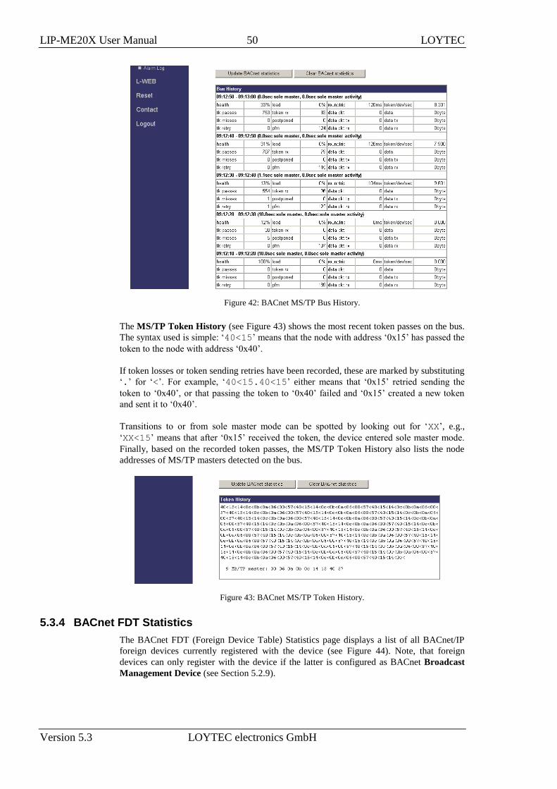
LIP-ME20X User Manual 50 LOYTEC
Version 5.3 LOYTEC electronics GmbH
Figure 42: BACnet MS/TP Bus History.
The MS/TP Token History (see Figure 43) shows the most recent token passes on the bus.
The syntax used is simple: ‘40<15’ means that the node with address ‘0x15’ has passed the
token to the node with address ‘0x40’.
If token losses or token sending retries have been recorded, these are marked by substituting
‘.’ for ‘<’. For example, ‘40<15.40<15’ either means that ‘0x15’ retried sending the
token to ‘0x40’, or that passing the token to ‘0x40’ failed and ‘0x15’ created a new token
and sent it to ‘0x40’.
Transitions to or from sole master mode can be spotted by looking out for ‘XX’, e.g.,
‘XX<15’ means that after ‘0x15’ received the token, the device entered sole master mode.
Finally, based on the recorded token passes, the MS/TP Token History also lists the node
addresses of MS/TP masters detected on the bus.
Figure 43: BACnet MS/TP Token History.
5.3.4 BACnet FDT Statistics
The BACnet FDT (Foreign Device Table) Statistics page displays a list of all BACnet/IP
foreign devices currently registered with the device (see Figure 44). Note, that foreign
devices can only register with the device if the latter is configured as BACnet Broadcast
Management Device (see Section 5.2.9).

LIP-ME20X User Manual 51 LOYTEC
Version 5.3 LOYTEC electronics GmbH
Figure 44: BACnet FDT Statistics page.
5.3.5 Packet Capture
The packet capture feature allows configuring and running a local packet capture for the
Ethernet and MS/TP ports. Please refer to Section 9.3 for more information on how to set
up local capture and configure remote packet capture with Wireshark.
5.4 Documentation
The documentation page allows to access documentation related to the device. See Section
5.2.17 on how to configure documentation links and upload documentation files accessible
via this page.
Figure 45: Documentation Page.
Note: The Documentation page and all files available on it are accessible for all users (incl.
Guest).
5.5 Reset, Contact, Logout
The menu item Reset allows the following essential operations:
Rebooting the device from a remote location.
The Contact item provides contact information and a link to the latest user manual and the
latest firmware version. The Logout item closes the current session.

LIP-ME20X User Manual 52 LOYTEC
Version 5.3 LOYTEC electronics GmbH
6 Operating Interfaces
6.1 BACnet Interface
6.1.1 Device Object
The BACnet interface provides one Device object supporting the properties shown in Table
5. The Conformance Code column determines whether accessing the property via BACnet
services is possible in a read-writable (W) or read-only (R) manner. The following sections
describe the Device object’s properties in detail.
BACnet Property Identifier BACnet Datatype Conformance Code
Object_Identifier BACnetObjectIdentifier R
Object_Name CharacterString R
Object_Type BACnetObjectType R
Vendor_Name CharacterString R
Vendor_Identifier Unsigned16 R
Model_Name CharacterString R
Firmware_Revision CharacterString R
Application_Software_Version CharacterString R
Location CharacterString W
Description CharacterString W
Protocol_Version Unsigned R
Protocol_Revision Unsigned R
Protocol_Services_Supported BACnetServicesSupported R
Protocol_Object_Types_Supported BACnetObjectTypesSupported R
Object_List BACnetARRAY[N] of
BACnetObjectIdentifier
R
Database_Revision Unsigned R
Max_APDU_Length_Accepted Unsigned R
Segmentation_Supported BACnetSegmentation R
Max_Segments_Accepted Unsigned R
APDU_Segment_Timeout Unsigned W
APDU_Timeout Unsigned W
Number_Of_APDU_Retries Unsigned W
Max_Master Unsigned(1..127) R
Max_Info_Frames Unsigned R

LIP-ME20X User Manual 53 LOYTEC
Version 5.3 LOYTEC electronics GmbH
BACnet Property Identifier BACnet Datatype Conformance Code
System_Status BACnetDeviceStatus R
Device_Address_Binding List of BACnetAddressBinding R
Active_COV_Subscriptions List of BACnetCOVSubscription R
UTC_Offset Integer W
Daylight_Savings_Status Boolean R
Local_Date Date R
Local_Time Time R
Time_Synchronization_Recipients List of BACnetRecipient W
UTC_Time_Synchronization_Recipiens List of BACnetRecipient W
Time_Synchronization_Interval Unsigned W
Align_Interval Boolean W
Interval_Offset Unsigned W
Configuration_Files BACnetARRAY[N] of
BACnetObjectIdentifier
R
Last_Restore_Time BACnetTimeStamp R
Slave_Proxy_Enable1 BACnetARRAY[N] of Boolean W
Auto_Slave_Discovery1 BACnetARRAY[N] of Boolean W
Manual_Slave_Address_Binding1 List of BACnetAddressBinding W
Slave_Address_Binding1 List of BACnetAddressBinding R
Table 5: Properties of the Device Object. 1 Only available if the device is a BACnet/IP-BACnet MS/TP router.
6.1.2 Device Name and ID
The following properties of the Device object, which are part of every BACnet object,
identify the device uniquely.
Object_Identifier (Read-Only). This property, of type BACnetObjectIdentifier, is a
number that identifies the object. For the Device object, this number must be unique
internetwork-wide.
The Object_Identifier number consists of two parts, a number defining the object’s type and
an instance number. The object type “Device” is assigned the number 8. The instance
number of the Object_Identifier of the Device object can be configured, see Section 5.2.8.
The default value of this instance number is 17800.
Object_Name (Read-Only). The name of the object. For the Device object, this is the
BACnet name under which the device is visible in the BACnet inter-network. The device’s
name shall be unique within the BACnet internetwork. The device’s name is configurable,
see Section 5.2.8.
Object_Type (Read-Only). A number designating the object’s type. For the Device object,
this number is 9.
6.1.3 Device Information
A whole set of properties of the Device object provide general purpose information about
the device.
Vendor_Name (Read-Only). The value of this property is “LOYTEC electronics GmbH”.
Vendor_Identifier (Read-Only). A numerical value identifying the BACnet vendor. The
value of this property is 178.

LIP-ME20X User Manual 54 LOYTEC
Version 5.3 LOYTEC electronics GmbH
Model_Name (Read-Only). The value of this property is equal to the product code of the
device, i.e., its value is “LIP-ME201”.
Firmware_Revision (Read-Only). The value of this property gives the current firmware
version of the device.
Application_Software_Version (Read-Only). The value of this property gives the build
date and the version of the current firmware.
Location (Read-Writable). A string intended to be used to describe the location of the
device, e.g., “1st floor”. This property can be set via the configuration UI, see Section 5.2.8.
The default value is “unknown”.
Description (Read-Only). A string intended to hold a user specified description of the
device. This property can be changed via the configuration UI, see Section 5.2.8.
Protocol_Version (Read-Only). The BACnet protocol version supported by the device.
The value of this property is 1.
Protocol_Revision (Read-Only). The BACnet protocol revision of the BACnet version
supported by the device. The value of this property is 5.
Protocol_Services_Supported (Read-Only). A string of bits marking which BACnet
services can be executed by the device. For a detailed list of the BACnet services supported,
please refer to the product’s PICS document.
Protocol_Object_Types_Supported (Read-Only). A string of bits identifying which
BACnet object types are supported by the device. For a detailed list of supported object
types, please refer to the product’s PICS document.
6.1.4 Object Database
The following properties of the Device object provide information about the BACnet
objects contained in the device.
Object_List (Read-Only). This property holds a sequence of object IDs (object type,
object instance pairs), one object ID for each object within the device that is accessible
through BACnet services.
Database_Revision (Read-Only). This property, of type Unsigned, is a logical revision
number for the device's object database. It is incremented when an object is created, an
object is deleted, an object's name is changed, an object's Object_Identifier property is
changed, or a restore is performed.
6.1.5 Protocol Parameters
BACnet protocol parameters are accessible via the Device object properties listed below.
Max_APDU_Length_Accepted (Read-Only). The maximal size of a BACnet APDU
(Application Protocol Data Unit) accepted by the device. The value of this property is 487
if BACnet MS/TP is used and 1476 if BACnet/IP is used. When the device can act as a
router between BACnet/IP and BACnet MS/TP, the value of this property is 1476.
Segmentation_Supported (Read-Only). The value of this property indicates whether and
which kind of segmentation is supported by a device. The value of this property is
SEGMENTED_BOTH.
Max_Segments_Accepted (Read-Only). The maximum numbers of segments accepted by
a device. The value of this property is 16.

LIP-ME20X User Manual 55 LOYTEC
Version 5.3 LOYTEC electronics GmbH
APDU_Segment_Timeout (Read-Writable). Time in milliseconds allowed between two
consecutive segments. The value of this property is 2000 milliseconds by default. On
MS/TP networks, this value should be increased to 40000 (40 sec).
APDU_Timeout (Read-Writable). Time in milliseconds the device waits for an answer
before retrying or giving up on a request; also see Number_Of_APDU_Retries. The value of
this property is 3000 milliseconds by default. On MS/TP networks, this value should be
increased to 60000 (1 min).
Number_Of_APDU_Retries (Read-Writable). The number of times the device will try to
re-send a packet before giving up on a request; also see APDU_Timeout. The value of this
property is 3 by default.
Max_Master (Read-Writable). This property is only present if BACnet MS/TP is enabled.
It defines the maximal MS/TP MAC number at which the device expects an MS/TP master.
The value of this property is configurable, see Section 5.2.10, and must be in the range 1-
127. The default value of this property is 127.
Max_Info_Frames (Read-Writable). This property is only present if BACnet MS/TP is
enabled. It defines the maximal number of MS/TP packets the device can send when it
holds the MS/TP token. Increasing this value will increase the MS/TP bandwidth of the
device at the cost of other device’s bandwidth. The value of this property is configurable,
see Section 5.2.10. The default value of this property is 1.
6.1.6 Diagnostics
Several Device object properties provide run-time information about the device.
System_Status (Read-Only). The value of this property is always OPERATIONAL.
Device_Address_Binding (Read-Only). This property contains a list of bindings between
BACnet device instance numbers (the instance number part of the Device object ID) and
BACnet addresses. This property tells a user which BACnet address the device will actually
use when trying to communicate with another device known only by its device instance
number. This information can be helpful when diagnosing network configuration problems.
Important: A BACnet address consists of the BACnet network number, which is 0 for the local
network, and the BACnet MAC address of the device.
In particular, if two or more devices in the network have been wrongly assigned the same
device instance number, two BACnetAddressBinding entries with the same instance number
but different BACnet addresses will be listed—provided the ambiguous instance number is
in some way required by the device (e.g., in the course of a client mapping).
Important: Bindings between device instance numbers and BACnet addresses are only listed in
Device_Address_Binding if they are actually required by a given configuration, and are
currently known or ambiguous.
Slave_Address_Binding (Read-Only). This property is only present if the device is a
BACnet/IP-BACnet MS/TP router. It lists bindings between BACnet MS/TP slave instance
numbers (the instance number part of the slave’s Device object ID) and BACnet addresses
of slaves on the MS/TP network for which the device serves as a slave proxy, see Section
6.1.10 for details.
Active_COV_Subscriptions (Read-Only). This property lists currently active COV
subscriptions.. Each entry of type BACnetCOVSubscription provides information about the
recipient address, the monitored property ID, whether notification are confirmed or
unconfirmed, the remaining time of the subscription, and optionally the COV increment.

LIP-ME20X User Manual 56 LOYTEC
Version 5.3 LOYTEC electronics GmbH
Whenever the device receives a valid COV subscription via one of the BACnet services
SubscribeCOV or SubscribeCOVProperty, a new entry is added to the list or an existing
entry is updated (re-subscription). An entry is removed from Active_COV_Subscriptions
when a subscription terminates, either because it times out or because it is actively
unsubscribed by the subscriber.
6.1.7 Date & Time
The device’s time and date are exposed to the network via the following set of Device
object properties.
UTC_Offset (Read-Writable). This Integer value specifies the time difference between
local time and UTC in minutes, effectively determining the time zone. The value of this
property is configurable, see Section 5.2.1.
Important! Note that UTC_Offset is relative to local time and not relative to UTC, i.e., a time zone
offset of GMT+1 (Berlin, Paris, Vienna) corresponds to UTC_Offset being set to -60
(minutes).
Daylight_Savings_Status (Read-Only). This Boolean value indicates whether (TRUE) or
not (FALSE) daylight saving correction of the local time is currently active. The daylight
saving scheme is configurable, see Section 5.2.1.
Local_Date (Read-Only). The current date according to the device’s clock. The value of
this property can be changed via the configuration UI, see Section 5.2.1.
Local_Time (Read-Only). The current time according to the device’s clock. The value of
this property can be changed via the configuration UI, see Section 5.2.1.
6.1.8 Time Master
The device can serve as a BACnet time master, i.e., it can issue TimeSynchronization and
UTCTimeSynchronization request on time synchronization events. A time synchronization
event occurs after rebooting, when the device’s clock changes, and, if so configured,
periodically. The following properties of the Device objct are used to configure the time
master.
Time_Synchronization_Recipients (Read-Writable). This list of recipients will receive
TimeSynchronization requests on time synchronization events. A recipients is either
specified by its device ID (the object ID of its Device object), or its BACnet address.
UTC_Time_Synchronization_Recipients (Read-Writable). This list of recipients will
receive UTCTimeSynchronization requests on time synchronization events. A recipients is
either specified by its device ID (the object ID of its Device object), or its BACnet address.
Time_Synchronization_Interval (Read-Writable). The Unsigned value of this property
specified the time interval in minutes in which periodic time synchronization events are
created. If set to zero, no periodic time synchronization events are generated.
The actual clock time at which periodic time synchronization events are generated is
determined by the properties Time_Synchronization_Interval, Align_Interval, and
Interval_Offset; Table 6 outlines how these properties interact.

LIP-ME20X User Manual 57 LOYTEC
Version 5.3 LOYTEC electronics GmbH
Time_Synchronization_Interval Align_Intervals Periodic Time Synchronization Event At …
Multiple of 1440 (minutes), i.e.,
multiple of one day
TRUE Interval_Offset minutes after midnight, every
(Time_Synchronization_Interval/1440) days
Multiple of 60 (minutes) but not
multiple of 1440 (minutes), i.e.,
multiple of one hour
TRUE Interval_Offset minutes from the current* hour,
every (Time_Synchronization_Interval/60) hours
Multiple of 1440 (minutes), i.e.,
multiple of one day
FALSE Interval_Offset minutes from the current* minute,
every (Time_Synchronization_Interval/1440)
days
Multiple of 60 (minutes), but
not multiple of 1440 (minutes),
i.e., multiple of one hour
FALSE Interval_Offset minutes from the current* minute,
every (Time_Synchronization_Interval/60) hours
Neither multiple of 60 or 1440,
but greater than zero
TRUE or
FALSE
Interval_Offset minutes from the current* minute,
every Time_Synchronization_Interval minutes
Zero TRUE or
FALSE
never
Table 6: Periodic time synchronization events are parameterized by the properties
Time_Synchronization_Interval, Align_Interval, and Interval_Offset. * Current hour or minute refers to the hour or minute at which one of the properties
Time_Synchronization_Interval, Align_Interval, and Interval_Offset is set, e.g., the hour or minute
the device completes a boot process or one of these properties is modified via BACnet services.
By default, the value of Time_Synchronization_Interval is 1440 (minutes), i.e., one day.
Align_Intervals (Read-Writable). The Boolean value of this property determines whether
or not periodic time synchronization events shall be anchored at the start of a day or hour
(TRUE) or not (FALSE), provided Time_Synchronization_Interval is a multiple of a day
(1440 minutes) or hour (60 minutes). Table 6 details on how this property influences
generating periodic time synchronization events. The default value of this property is
TRUE.
Interval_Offset (Read-Writable). While Time_Synchronization_Interval specifies the
period in which time synchronization events are generated, the Unsigned value of this
property determines the point of time in minutes within this interval at which the time
synchronization event is actually triggered. If the value of Interval_Offset is larger than the
value of Time_Synchronization_Interval, the remainder of Interval_Offset divided by
Time_Synchronization_Interval is used. The default value of this property is 0.
6.1.9 Backup & Restore
The following properties of the Device object are related to backup & restore procedures.
Configuration_Files (Read-Only). The contents of this property is an array of object IDs
of File objects that can backed-up or restored during a BACnet backup or restore procedure.
Outside a BACnet backup or restore procedure, this property is empty. After a BACnet
backup or restore procedure has been initiated, it contains the object ID (File, 0), i.e., the
File object whose instance number is 0.
Last_Restore_Time (Read-Only). The BACnetTimeStamp of the last restore procedure.
6.1.10 Slave Proxy
A device configured as BACnet/IP-BACnet MS/TP router, can serve as a slave proxy i.e.,
the device can answer Who-Is broadcast requests with I-Am responses for BACnet MS/TP
slaves which, by definition, cannot initiate any communication and, thus, cannot answer
broadcasts. The following Device object properties allow to configure and monitor the slave
proxy.

LIP-ME20X User Manual 58 LOYTEC
Version 5.3 LOYTEC electronics GmbH
Slave_Proxy_Enable (Read-Writable). For each BACnet MS/TP port, this property
contains a Boolean that allows a user to enable (TRUE) or disable (FALSE) the slave proxy
for the given port. By default, the slave proxy is enabled on all MS/TP ports.
Auto_Slave_Discovery (Read-Writable). For each BACnet MS/TP port, the slave proxy
is capable of auto-detecting slaves on the MS/TP network attached to the port. This auto-
detection mechanism can be disabled (FALSE) or enabled (TRUE) by changing the
Boolean values stored in this property. Aside from auto-detecting slaves, the presence of
slaves can also be manually configured using the property Manual_Slave_Address_Binding.
By default, slave auto-detection is enabled on all MS/TP ports.
Note: Due to bandwidth and latency limitations on MS/TP networks, the auto-discovery process
may initially take up to 10min. However, once, slaves have been discovered, slaves will be
quickly re-discovered after reboots or power-outs since the slave proxy caches information
about slaves found on the MS/TP networks. To speed up auto-detection of slaves newly
added to an existing MS/TP network for which auto-detection is enabled, simply disable
and then re-enable auto-detection on given MS/TP port, i.e., set Auto_Slave_Discovery for
the port to FALSE and then back to TRUE.
Manual_Slave_Address_Binding (Read-Writable). Aside from auto-detecting slaves,
see Auto_Slave_Discovery, slave bindings can also be manually configured via this
property. Each entry of this list is a BACnetAddressBinding, i.e., a pair consisting of a slave
device’s instance number and its BACnet address. Note, that bindings in this list may not
necessarily appear in the property Slave_Address_Binding, e.g., if for a given binding no
physical slave is present at the respecive MS/TP MAC address.
Important: Only use Manual_Slave_Address_Binding if the slave is not auto-detected. Note, that
bindings in Manual_Slave_Address_Binding must contain the correct network number
of the MS/TP network to which the slave is attached.
Slave_Address_Binding (Read-Only). This property lists bindings of instance numbers
and BACnet addresses of all slaves for which the slave proxy answers Who-Is requests.
Thus, this property can be used to check if slaves have been auto-discovered or manually
bound successfully. The property is also helpful in discovering network configuration issues
involving slaves: If two or more slaves on the attached MS/TP networks have been
erroneously assigned the same device instance number (the instance number of the slave’s
Device object), the given instance number will be listed accordingly often in this property.
6.2 SNMP Interface
The Simple Network Management Protocol (SNMP) is a common protocol for monitoring
and managing devices. SNMP is an “Internet-standard protocol” and is defined by the
Internet Engineering Task Force (IETF). It is typically used in IT environments for server,
network and supply management and monitoring.
SNMP allows querying status and statistics data from devices and also allows devices to
alarm network management applications using SNMP traps. A managed device contains an
SNMP agent which communicates with a management system using UDP. The SNMP agent
holds collects and provides its data items in a tree. The data provided by an SNMP agent is
defined by Management Information Bases (MIBs). These define the names and data types
of the management data. Every data item is assigned an object ID (OID). A device can
support an arbitrary number of MIBs, such as CPU statistics or network traffic statistics.
6.2.1 SNMP Features
LOYTEC devices supporting SNMP share these common features:

LIP-ME20X User Manual 59 LOYTEC
Version 5.3 LOYTEC electronics GmbH
Read-only access for SNMP version 2C and 3
Standard MIBS: SNMPv2-MIB, SNMPv2-SMI, RFC1213-MIB, IF-MIB, IP-MIB,
DISMAN-EVENT-MIB, HOST-RESOURCES-MIB, SNMP-FRAMEWORK-
MIB, SNMP-MPD-MIB, SNMP-USER-BASED-SM-MIB, SNMP-VIEW-
BASED-ACM-MIB,
Option to expose OPC data points to SNMP.
Option to create a device-specific MIB file.
Option to send traps to a management system.
6.2.2 Configuration
The SNMP agent can be configured in the Web UI and in the configuration software. Figure
46 shows the Web interface. The settings in the configuration software are similar.
Figure 46: SNMP configuration page
The following settings are used to configure the SNMP agent:
SNMP Protocol version: This setting selects between version 2C, 3 and 2C+3.
Protocol version 2C is more common, but lacks encrypted authentication.
SNMP agent port: This select the UDP port on which the SNMP agent listens. It
is recommended to keep this port at its default setting, port 161.
SNMP System location: This defines the value of the SNMPv2-MIB::sysLocation
OID. It is used to locate a device via SNMP.
SNMP System contact: This defines the value of the SNMPv2-MIB::sysContact
OID. It is used to identify the responsible contact persion for the deivce
SNMP Trap address: This setting defines the destination IP address to which
traps (alarms) are sent.
SNMP Trap port: This setting defines the destination UDP port to which traps
(alarms) are sent.

LIP-ME20X User Manual 60 LOYTEC
Version 5.3 LOYTEC electronics GmbH
SNMP Trap user: This setting defines the user name when sending traps (SNMP
v3).
SNMP Community string: This defines the (read) community string used for
SNMP v2c.
SNMP User name: This defines the user name required to access the SNMP agent
(SNMP v3).
SNMP User password: This defines the user password required to access the
SNMP agent (SNMP v3).
Expose data points: This switch allows to access data points exposed to OPC also
to be accessed via SNMP.
6.2.3 Exposing Data Points to SNMP
The SNMP agent allows exposing data points to SNMP. It considers every data point which
is exposed via OPC also to be exposed via SNMP.
As SNMP has several restrictions on what can be represented, the following mappings are
made:
Binary data points. Binary data points are mapped to the INTEGER type. FALSE
is mapped to 0, TRUE is mapped to 1 and an invalid value is mapped to -1.
Analog data points: SNMP has no standard way to represent floating point
values, so their values are mapped to the STRING type. A value of “--“ identifies
an invalid value
Multistate data points: Multistate data points are mapped to the STRING data
type. Their values are represented by the multi-state text labels.
SNMP variable names have to be unique within their MIB, so data points with the same
name in different folders are made unique by the following name scheme:
dpNNNNXUUUUUUUU, e.g. dpFreeMemoryX00000003. NNNN is the data point name with all
forbidden characters removed (only a-z, A-Z and 0-9 is allowed). UUUUUUUU is replaced
with the unique ID of the data point.
Figure 47: Downloading device-specific MIB files
Figure 47 shows the Web UI page which allows downloading the device specific MIB file.
The “Download MIB file” buttons generates a MIB file which can be used by a network

LIP-ME20X User Manual 61 LOYTEC
Version 5.3 LOYTEC electronics GmbH
management tool. The “Download XML file” button generates an XML-encoded
representation of the MIB contents.
Note that the MIB files are dependent on the data point configuration, so that changes in the
data point configuration will change the MIB contents.
6.2.4 SNMP Security
As SNMP provides access to internal device information which could be exploited for an
attack, SNMP should be used only in internal, non-critical environments.
SNMP Version 2C uses unencrypted authentication and payload. The community string is
transmitted in clear text and can be easily extracted from captured network traffic.
SNMP Version 3 supports encrypted authentication and payload encryption. LOYTEC
devices support only authentication. The password is not transmitted in clear text then.
LOYTEC devices do not support write accesses via SNMP.

LIP-ME20X User Manual 62 LOYTEC
Version 5.3 LOYTEC electronics GmbH
7 Network Media
7.1 MS/TP
MS/TP is an RS-485 protocol and usually needs three wires (negative, positive, and
reference). Polarity must be connected correctly. When using 2-wire MS/TP, earth ground
must be connected to the negative terminal of the power supply. Never connect the positive
terminal of the power supply to earth ground! See Section 4.9 for wiring instructions. Each
MS/TP network segment must be properly terminated. Use an LT-04 network terminator
connected at each of the two ends of the segment media.
The RS-485 transceiver of the device represents a full-load on the RS-485 bus.
Consequently, a minimum of 31 devices are supported on the MS/TP channel. More devices
may be possible, if they represent half-load or quarter-load. Please consult the third-party
documentation. If more MS/TP devices need to be connected, use an RS-485 repeater to
separate them electrically.
Logically, the MS/TP bus supports up to 255 devices. Each MS/TP device must be assigned
a unique MAC address. Up to 127 MS/TP masters can be connected. Make sure, that the
Max_Master setting includes the highest MS/TP master MAC address.
For operation of some slower devices on the MS/TP network it is recommended to set the
following properties of the device object to fine-tune communication on the network:
APDU_Timeout = 60000 (1 min).
APDU_Segement_Timeout = 40000 (40 sec).
Optionally, disable MS/TP slave proxy if not needed in order to optimize bandwidth
usage: Slave_Proxy_Enable = { False }.
7.2 Redundant Ethernet
7.2.1 Ethernet Cabling Options
The LIP-ME204 model is equipped with two Ethernet ports, which are connected to an
internal Ethernet switch. This allows for advanced cabling options to reduce cabling costs
or to increase network resilience. For this discussion, the term upstream is used to designate
the direction towards the network, which the devices are connected to. Likewise, the term
downstream is used to designate devices more distant to the network which the devices are
connected to.
Redundant cabling options are enabled by the Rapid Spanning Tree Protocol (RSTP) which
is implemented in most managed switches. Please note, that this is a feature of the switch,
not of the LIP-ME20X, so that LOYTEC cannot give a guarantee that this will work with a

LIP-ME20X User Manual 63 LOYTEC
Version 5.3 LOYTEC electronics GmbH
particular switch model. In no case redundant cabling options will work with unmanaged
switches. The older Spanning Tree Protocol (STP) should not be used for this type of
application, as it converges too slowly.
Star topology: In the most basic setup, a device is connected to an Ethernet switch with one
cable. This is called a star cabling because all devices are connected to a common upstream
device. In this setup, the cable and the switch are single point of failures.
Chain topology: Because the LIP-ME20X itself acts as an Ethernet switch, this device can
be connected to a chain. This is a special form of the star topology. Its advantage is the
reduced cabling costs. The disadvantage is the connection loss to downstream devices when
an upstream device is powered-off, reset or removed. Also, the Ethernet bandwidth (100
MBit/s) is shared among all members of the chain. The last device has one unused Ethernet
port, as it is not allowed to create Ethernet loops without STP. The recommended maximum
number of daisy-chained devices is 20.
LINX-151
192.168.44.10
1 2
Upstream Switch 1
1 2 3 4
Upstream Switch 2
1 2 3 4
LINX-151
192.168.44.11
1 2
Sw
itch1
19
2.1
68
.44
.2 23
45
1
Sw
itch2
19
2.1
68.4
4.3
23
45
1
LINX-151
192.168.44.12
1 2
Figure 48: Fully redundant Ethernet topology
Fully redundant topology: Both Ethernet ports are connected to a different upstream
switch. Thus, a single cable or upstream switch problem can be tolerated. This topology
requires RSTP. In Figure 48, the LINX-151 with IP addresses 192.168.44.10 to
192.168.44.12 are connected in this way. This connection scheme increases switch and
cabling costs, but increases network resilience. Note that the upstream network is connected
via the lowest-numbered ports. If this is not possible, the ports need to be configured to the
lowest STP port priority value (which is the highest priority).
Ring topology: In this setup, the devices are connected in a chain and each end of the chain
is connected to a different upstream switch. This topology requires RSTP. If a single device
is powered off, the RSTP will automatically recalculate the spanning tree so that all other
devices in the chain are reachable. Only if two devices are power-off at the same time, the
devices between them will not have an Ethernet connection. In Figure 49, the L-INX
devices with IP addresses from 192.168.44.10 to 192.168.44.12 are connected in this way.
The recommended maximum number of daisy-chained devices is 20.

LIP-ME20X User Manual 64 LOYTEC
Version 5.3 LOYTEC electronics GmbH
LINX-151
192.168.44.10
1 2
Upstream Switch 1
1 2 3 4
Upstream Switch 2
1 2 3 4
LINX-151
192.168.44.11
1 2
Sw
itch
1
19
2.1
68
.44
.2 23
45
1
Sw
itch
2
19
2.1
68
.44
.3
23
45
1LINX-151
192.168.44.12
1 2
Figure 49: Ring Ethernet topology
7.2.2 Upstream Options
In case of redundant switches, there are two possible upstream topologies:
Single upstream connection: Switch1 (or Switch2, but not both) is connected to the
upstream network while Switch2 only provides a redundant path to the LOYTEC devices.
The redundant path is created by a direct Ethernet cable between Switch1 and Switch2
which needs to be plugged into a lower-numbered port than the LIP-ME20X devices are
connected to. If this is not possible, the STP port priority for the cross-connection cable
needs to be set to a low value. The RSTP domain should be restricted to Switch1 and
Switch2. This can be done by enabling a BPDU filter on the port on Upstream Switch 1.
This will block all RSTP packets to enter the upstream network. A sample setup for this
topology is shown in Figure 50.
LINX-151
192.168.44.10
1 2
Upstream Switch 1
1 2 3 4
LINX-151
192.168.44.11
1 2
Sw
itch
1
19
2.1
68
.44
.2 23
45
1
Sw
itch
2
19
2.1
68
.44
.3
23
45
1
Direct Ethernet cable between Switch1 and Switch2
LINX-151
192.168.44.12
1 2
Figure 50: Single upstream connection.
Redundant upstream connection: Switch1 and Switch2 are both connected to the
upstream network, either to two ports on the same switch or to two redundant upstream
switches. In this case, RSTP is needed to ensure a loop-free topology between the upstream
switches, Switch1 and Switch2, so the RSTP domain includes the upstream network and the
chained LOYTEC devices. The configuration of Switch1 and Switch2 need to ensure that
they are not selected as the root bridge. If possible device communication should be bound
to a separate VLAN and MSTP (Multiple Spanning Tree Protocol) should be employed to
isolate the spanning tree operations. This topology is shown in Figure 48.
7.2.3 Preconditions
For the fully redundant and ring topology, the following preconditions have to be met:

LIP-ME20X User Manual 65 LOYTEC
Version 5.3 LOYTEC electronics GmbH
The upstream switches have to support the Rapid Spanning Tree Protocol (RSTP),
as defined in IEEE 802.1w.
The upstream switches have to provide a broadcast storm filter.
Two distinct switches are required for each end of the device chain.
Both upstream switches are connected to the same Ethernet network.
7.2.4 Switch Settings
The switches which connect the devices to the network need the following settings. Note
that these are only recommendations or starting points. Each network with redundant
connections needs testing and verification to prevent network loops.
The STP bridge must be enabled.
The STP bridge priority should be set to the minimum (61440), so that these
switches are not elected as root bridges.
The bridge mode should match the upstream bridge modes, preferable 802.1s or
802.1w.
If the upstream network uses RSTP, the timing parameters of the upstream networks must
be used. Else the timing parameters should be set to minimum values for fast convergence:
Bridge max age time: 6 seconds
Hello time: 1 seconds
Forward delay: 4 seconds
All ports connected to Ethernet rings have to be configured as NON-EDGE ports,
so that the RSTP can detect loops
The switches should be configured to block broadcast storms. A recommended rate
is 5% or 3000 packets/seconds.
The upstream switches need the following configuration:
If a single upstream connection is used, the connected port on the upstream switch
should have BPDU filtering enabled.
If redundant upstream connections are used, the connected ports on the upstream
switches should have a BPDU root guard enabled.
7.2.5 Testing
When the switches are configured and the devices are connected, the following tests are
recommended. These tests are important to confirm that the STP changes due to topology
changes to not interfere with the rest of the network.
Check that no broadcast storms are sent into the upstream network by capturing
traffic between Switch1, Switch2 and the Upstream switch. This test should be
done continuously, especially during switch and device power cycles.
Check that all devices can be reached (ICMP ping).
Execute these tests for these conditions:

LIP-ME20X User Manual 66 LOYTEC
Version 5.3 LOYTEC electronics GmbH
Power up all switches and devices. Wait until all devices are up, then test.
Power-off Switch1. Wait approx. 10 seconds, then test.
Power-on Switch2, power-off Switch1. Wait until Switch2 has booted, then test.
Power-on Switch1. Wait until Switch1 has booted, then test.
Reboot all LOYTEC devices. Wait until the devices have booted, then test.
Remove a single Ethernet cable. Wait approx. 10 seconds, then test. This test
should be repeated for different cables. Make sure that at least the following
connections are tested:
The connection between Switch1 and the LIP-ME20X directly connected
to Switch1.
The connection between Switch2 and the LIP-ME20X directly connected
to Switch2.
A connection in the LIP-ME20X chain which is not connected directly to
either Switch1 or Switch2.
7.2.6 Example switch configuration
The following example shows the configuration commands for Switch1, Switch2 and the
upstream switch (HP Procurve syntax) in the setup shown in Figure 48.
Upstream switches:
config
spanning-tree
spanning-tree priority 8
spanning-tree 3,4 root-guard
spanning-tree hello-time 1
spanning-tree forward-delay 4
spanning-tree maximum-age 6
exit
Switch1 and Switch2:
config
spanning-tree
spanning-tree priority 15
spanning-tree 1,2 port-priority 0
spanning-tree 3-5 port-priority 8
spanning-tree hello-time 1
spanning-tree forward-delay 4
spanning-tree maximum-age 6
exit
7.3 WLAN
7.3.1 Introduction
Devices supporting the LWLAN-800 wireless adapter can be connected to IEEE 802.11
wireless networks. The following operation modes are supported:
Client mode (separate network): The WLAN client connected to an existing
access point. The firewall of the WLAN interface can be configured to provide

LIP-ME20X User Manual 67 LOYTEC
Version 5.3 LOYTEC electronics GmbH
only a subset of the services of the device. For example, the WLAN interface could
expose the Web UI, but not BACnet communication.
Access point mode (separate network): In the isolated access point mode, a
client can connect to the wireless network created by the device. The device will
assign an IP address to the client and will redirect all traffic to itself. This mode is
used to configure a device with a mobile device.
Access point mode (bridged): In the bridged access point mode, a client can
connect to the access point and also can use the network devices on the bridged
Ethernet device. In this mode, the DHCP server is deactivated to avoid interference
with an existing DHCP server in the Ethernet network.
Mesh point (separate network): This mode is used to create an IEEE 802.11s
mesh network. Mesh points communicate with other mesh points in their radio
vicinity and automatically choose the best route. Mesh networks can be used to
extend the range of a wireless network or to create redundant radio links.
Mesh point (bridged): This mode is like the mesh point mode and also bridges the
mesh point to an Ethernet network. Thus devices in the Ethernet network can
communicate with devices in the mesh network. Only one mesh point should be in
the bridged mode to avoid network loops.
The LWLAN-800 interface can use two WLAN functions at the same time. This can be
used for advanced setups, like:
Wireless 1 is used as an access point for configuring the device, while the
Wireless 2 interface is used to participate in a mesh network.
Wireless 1 is used as a bridged access point for configuring the device and the
devices on the Ethernet network while Wireless 2 connects to another wireless
network to reach a remote device.
However, there are restrictions when using both interfaces at the same time:
Both functions need to use the same radio band.
Both functions need to use the same channel.
7.3.2 802.11s Mesh Networking
WLAN client and access point modes are similar to other devices using 802.11 wireless
networks. This section explains the features and benefits of the 802.11s network.
A mesh network removes the roles of clients and access points. Every node in a mesh
network can send and receive data, as in a normal wireless network. However, every mesh
node also routes packets to other mesh nodes. It observes the signal strength to all reachable
nodes and distributes this information to other mesh nodes. Thus, the mesh network can
transmit data between nodes with are not in their radio vicinity. In this case, a path between
sender and receiver is selected and the intermediate nodes transmit the packet over several
hops.
As the signal strenght and thus the range of a node can change over time, as well as nodes
can be added and removed, the best path can change. The 802.11s routing protocol takes
this into account and changes paths dynamically.
802.11s also provides strong encryption using the AuthSAE (Simultaneous Authentication
of Equals) protocol, so that each pair of mesh nodes use an encrypted link. It is resistant to
passive, active and dictionary attacks, given a strong pre-shared key.

LIP-ME20X User Manual 68 LOYTEC
Version 5.3 LOYTEC electronics GmbH
Figure 51: Mesh Networking
Figure 51 shows the roles of mesh nodes and possible links. Mesh point 1 can communicate
with point 2 and point 3. It learns that the mesh point 2 is the mesh portal, so all traffic
leaving the mesh network is automatically routed towards mesh point 2.
Mesh point 4 has mesh point 2 and 3 in its radio vicinity, but cannot communicate directly
with mesh point 1. So mesh points 1 to 4 have two ways to reach each other and can tolerate
the failure of a single node. This makes a mesh network resilient to node failure or fading
radio links.
Mesh point 6 is an example on how mesh networks can be used to extend radio range. If
point 2 communicates with point 6, there are two possible paths: 2-4-5-6 and 1-3-5-6. It
selects the better path and mesh point 5 will extend the network range.
This example shows that every additional mesh point can make the network more resilient
to failures or can extend the range far beyond the range of a single radio.
7.3.3 Hardware Installation
Connect the LWLAN-800 interface to the device with a USB cable, and then power the
device. Do not remove the interface during operation.
The LWLAN-800 supports two antennas which should be mounted outside any metallized
housing.
1
2
3
4
5 6
Ethernet
Mesh Portal
Mesh Node

LIP-ME20X User Manual 69 LOYTEC
Version 5.3 LOYTEC electronics GmbH
8 Firmware Update
The LIP-ME20X firmware supports remote firmware upgrade over the network and the
serial console.
To guarantee that the LIP-ME20X is not destroyed due to a failed firmware update, the
firmware consists of two images:
LIP-ME20X fallback image,
LIP-ME20X primary image.
The LIP-ME20X fallback image cannot be changed. Thus, if the update of the primary
image fails or the image is destroyed by some other means, the fallback image is booted and
allows reinstalling a valid primary image.
When the LIP-ME20X boots up with the fallback image, the status LED is flashing red.
8.1 Firmware Update via FTP
The LIP-ME201 primary image can be updated using any FTP client. Connect to the
LIP-ME201 using its IP address and the admin account (user ‘admin’, password of admin
account, see Section 5.2.4). Then change to the folder ‘dev’ and overwrite the file
‘bacrtr_lc3k_primary.dl’ with the new firmware. The LIP-ME201 will automatically reboot
after the file has been transferred.
8.2 Firmware Update via the Console
To download the firmware via the console interface, the LIP-ME201 must be connected to
the RS-232 port of a PC via its console interface as described in Section 9.2.1. You will
need the LOYTEC serial upgrade tool (LSU Tool), which can be downloaded from our
homepage at www.loytec.com.
Please make sure that the LIP-ME201 console shows the main menu otherwise navigate to
the main menu or simply reset the LIP-ME201.
To Upgrade via the Console
1. Double click on the *.dlc file that comes with the new firmware package. This should
start the LSU Tool and load the firmware image referenced in the dlc file. Please note
that the dlc file and the dl file must be stored in the same folder. The start window of
the LSU tool is shown in Figure 52.

LIP-ME20X User Manual 70 LOYTEC
Version 5.3 LOYTEC electronics GmbH
Figure 52: LSU Serial Upgrade Tool in Idle Mode
2. If the LIP-ME201 is not connected to COM1 you can change the port to COM2,
COM3, or COM4. Make sure that the product shown under “Product” matches the
device you are upgrading. Press “Download” to start the download.
3. Wait till the download completes, which will take several minutes. The end of the
download process is marked by a dialog box popping up.
4. Double check that the new firmware is executed by selecting ‘1’ and pressing ‘Enter’ in
the console window. This will bring up the device information which shows the current
firmware version.
8.3 Firmware Update via the Web Interface
The device’s firmware can also be upgraded using the Web interface. This option can be
found in the Config menu under the Firmware item. For more details see Section 5.2.15.

LIP-ME20X User Manual 71 LOYTEC
Version 5.3 LOYTEC electronics GmbH
9 Troubleshooting
9.1 Technical Support
LOYTEC offers free telephone and e-mail support for our LIP-ME20X product. If none of
the above descriptions solves your specific problem please contact us at the following
address:
LOYTEC electronics GmbH
Blumengasse 35
A-1170 Vienna
Austria / Europe
e-mail : [email protected]
web : http://www.loytec.com
tel : +43/1/40208050
fax : +43/1/402080599
or
LOYTEC Americas Inc.
N27 W23957 Paul Road
Suite 103
Pewaukee, WI 53072
USA
e-mail: [email protected]
web: http://www.loytec-americas.com
tel: +1 (512) 402 5319
fax: +1 (262) 408 5238
or
LOYTEC Asia Corporation Ltd.
16F.-3, No. 155, Zhongyang Rd
Xindian District
New Taipei City 23150
Taiwan
e-mail: [email protected]
tel: +886 (2) 8913 7838
fax: +886 (2) 8913 7830

LIP-ME20X User Manual 72 LOYTEC
Version 5.3 LOYTEC electronics GmbH
9.2 Statistics on the Console
9.2.1 Connecting to the Console
Use a PC terminal program with the communication settings set to 38,400 bps / 8 data bits /
no parity / 1 stop bit / no handshake. To connect COM1 of the PC to the Console on the
device, use a standard null-modem cable with full handshaking. Power up the device or
press Return if the device is already running. The menu shown in Figure 53 should appear
on the terminal.
Device Main Menu
================
[1] Show device information
[2] Serial firmware upgrade
[3] System configuration
[5] IP configuration
[7] BACnet configuration
[8] Reset configuration (factory defaults)
[9] Device statistics
[0] Reset device
Please choose:
Figure 53: Console Main Menu.
9.2.2 Reset configuration (load factory defaults)
Select item ‘8’ in the console main menu. This menu item allows resetting the device into its
factory default state. The menu appears as shown in Figure 54.
Reset Configuration Menu
========================
[1] Reset everything to factory defaults
[3] Reset all passwords
[q] Quit
Please choose:
Figure 54: Reset to Factory Defaults Menu.
Select option ‘1’ to reset the entire device to factory defaults (including error log,
configuration files, passwords etc.). Select option ‘3’ to reset all passwords (Web interface,
FTP server etc.) to factory defaults.
9.2.3 Device Statistics Menu
Select ‘9’ from the device main menu to get to the device statistics menu. This menu holds
relevant information regarding the device statistics of the device. This section describes
those statistics, which are not available on the Web UI. The device statistics menu is shown
in Figure 55. Use this menu only for debugging purposes. There is no need to access this
menu if the network is running smoothly.
Statistics Menu
===============
[4] Show IP statistics
[b] BBMD communications test
[q] Quit
Please choose:
Figure 55: Device Statistics Menu on the Console.
9.2.4 IP statistics
A sample console output is shown in Figure 56.

LIP-ME20X User Manual 73 LOYTEC
Version 5.3 LOYTEC electronics GmbH
*********** INTERFACE STATISTICS ************
***** lo0 *****
Address:127.0.0.1
Flags: Up Loopback Running Multicast
Send queue limit:50 length:0 Dropped:0
***** eth0 *****
Address:192.168.0.2 Broadcast Address:192.168.0.255
Flags: Up Broadcast Running Simplex Multicast
Send queue limit:50 length:0 Dropped:0
Network Driver Stats for CS8900 :
rx ready len - 50 rx loaded len - 0
rx packets - 931 tx packets - 165
rx bytes - 78480 tx bytes - 13627
rx interrupts - 931 tx interrupts - 165
rx dropped - 0 rx no mbuf - 0
rx no custers - 0 rx oversize errors - 0
rx crc errors - 0 rx runt errors - 0
rx missed errors - 0 tx ok - 165
tx collisions - 0 tx bid errors - 0
tx wait for rdy4tx - 0 tx rdy4tx - 0
tx underrun errors - 0 tx dropped - 2
tx resends - 0 int swint req - 2094
int swint res - 2094 int lockup - 0
interrupts - 3189
************ MBUF STATISTICS ************
mbufs: 512 clusters: 64 free: 14
drops: 0 waits: 0 drains: 0
free:461 data:51 header:0 socket:0
pcb:0 rtable:0 htable:0 atable:0
soname:0 soopts:0 ftable:0 rights:0
ifaddr:0 control:0 oobdata:0
************ IP Statistics ************
total packets received 922
datagrams delivered to upper level 922
total ip packets generated here 158
Destination Gateway/Mask/Hw Flags Refs Use Expire
Interface
default 192.168.0.1 UGS 6 0 0 eth0
62.178.55.77 192.168.0.1 UGH 0 1 3606 eth0
62.178.95.96 192.168.0.1 UGH 0 1 3606 eth0
81.109.145.243 192.168.0.1 UGH 0 1 3606 eth0
81.109.251.36 192.168.0.1 UGH 0 1 3606 eth0
127.0.0.1 127.0.0.1 UH 0 0 0 lo0
130.140.10.21 192.168.0.1 UGH 1 6 0 eth0
192.168.0.0 255.255.255.0 U 0 0 3 eth0
192.168.0.1 00:04:5A:26:96:1F UHL 7 0 1722 eth0
213.18.80.166 192.168.0.1 UGH 1 148 0 eth0
************ TCP Statistics ************
************ UDP Statistics ************
total input packets 924
total output packets 158
************ ICMP Statistics ************
Figure 56: IP Statistics.
The IP statistics menu has the additional feature of displaying any IP address conflicts. If
the device’s IP address conflicts with another host on the network, the banner shown in
Figure 57 is displayed.
WARNING: Conflicting IP address detected!
IP address 10.125.123.95 also used by device with MAC address
00 04 5A CC 10 41!
Clear IP conflict history (y/n):
Figure 57: IP Address Conflict.
As useful information, the MAC address of the conflicting host is shown. If the information
about this conflict shall be cleared, enter ‘y’. If ‘n’ is selected, the conflict will show up
again the next time this menu is entered.

LIP-ME20X User Manual 74 LOYTEC
Version 5.3 LOYTEC electronics GmbH
9.2.5 BBMD Communications Test
This statistics menu provides a simple test for the user to determine, which of the IP
addresses in the BDT are reachable over IP. The test uses a simple ping method on all IP
addresses of the BDT. A sample result is shown in Figure 58. IP addresses, which reply to
the ping request are shown as 'OK'. Others, that suffer from an error show 'FAILED'
including a comment on what the problem was.
BBMD Communications Test
============================
Address Result RTT(ms) Comment
------------------------------------------------------------------------
10.102.77.77:47808 OK 2
10.102.77.78:47808 FAILED n/a No ping reply.
10.102.77.79:47808 OK 1
10.102.77.80:47808 OK 1
Figure 58: BBMD communications test.
9.3 Packet Capture
9.3.1 Configure Remote Packet Capture
Remote packet capture is able to capture packets on the Ethernet port and on the MS/TP
port. The MS/TP remote packet capture option is only available, if the MS/TP port is
enabled on the device (see Section 5.2.10). To enable the remote packet capture feature, go
to the Ethernet port configuration and enable Remote packet capture as shown in Figure
59.
Figure 59: Remote packet capture port configuration.
The default Port setting may be changed to the desired port. Normally, this can be left at its
default. If No authentication is selected, the device will allow incoming capture
connections without requiring any credentials. If Username and Password is selected as
authentication method, the client Wireshark will be required to provide valid credentials
before the capture session can be started. Note, that only the users admin and operator are
allowed to connect if this authentication method is selected.
Click the Save Settings button to save the configuration. The changes take effect and do not
require to reboot the device. The remote capture can also be disabled again without a
reboot.
9.3.2 Enable Local Capture
The device provides a local capture feature. With local capture enabled the device logs
packets to an internal ring buffer. The log can be downloaded from the Web interface. To
verify that the device is set up correctly, go to Statistics Packet capture as shown in
Figure 60.

LIP-ME20X User Manual 75 LOYTEC
Version 5.3 LOYTEC electronics GmbH
Figure 60: Packet capture statistics.
Verify that the Ethernet and optionally the MS/TP capture ports are listed in the Available
capture ports table and that the Remote capture status for these ports reads
Disconnected. If the MS/TP port is not listed on a device that has an MS/TP port, make
sure that the MS/TP port is enabled in the port configuration.
To log offline without a Wireshark attached to the device, click the check box Local
Capture. The device will then start capturing packets and stores them in a ring buffer. The
log file can be downloaded by clicking on the button Download capture files. This stores a
ZIP archive of the packet capture to your local hard drive. Capture files can be cleared by
clicking Clear Files. After a reboot all local capture files are lost.
For local Ethernet capture additional capture filters can be added to narrow down the
amount of logged packets to those of interest. Select the line Ethernet port line and enter a
basic filter expression at the bottom of the page. Then click on Add and add more filters.
Finally click on Save Filters to store and activate the local capture filters. Figure 61 shows
an example filter for packets with source IP address 192.168.24.100.
Figure 61: Adding local Ethernet capture filters.
9.3.3 Run Wireshark Remote Capture
The remote packet capture requires the use of Wireshark 1.6.11 with WinPCAP 4.1.2.
Please update your Wireshark installation to this version or use a newer Wireshark version.
To add a remote capture port
1. Open Wireshark and choose the menu Capture Options… . This opens the
Capture Options dialog as shown in Figure 62.

LIP-ME20X User Manual 76 LOYTEC
Version 5.3 LOYTEC electronics GmbH
Figure 62: Wireshark Capture Options Dialog.
2. Click the Manage Interfaces button to open the Add new interfaces dialog.
3. Select the Remote Interfaces tab and click Add as shown in Figure 63.
Figure 63: Wireshark Add New Interfaces Dialog.
4. Enter the correct settings for Host and Port (default 2002) and, if authentication is
enabled, enter Username and Password in the corresponding fields as shown in Figure
64.
5. Note that only the users admin and operator are allowed to connect.

LIP-ME20X User Manual 77 LOYTEC
Version 5.3 LOYTEC electronics GmbH
Figure 64: Wireshark Remote Interface Dialog.
6. Click OK to retrieve the interface list from the device.
7. If the connection to the device was established successfully, the Remote Interfaces list
will be updated with information about all capture ports available on the device as
shown in Figure 65.
Figure 65: Added new interface to Wireshark.
8. Close the Add new interfaces and Capture Options dialogs to return to the main
window.
To Start a Remote Capture
1. Select the created remote interface from the interface list in the main window. It is
named ‘Raw Ethernet traffic’ for remote Ethernet dapture and ‘SNAP encapsulated
BACnet MS/TP traffic’ for remote MS/TP capture.
2. Click the Start button as shown in Figure 66.

LIP-ME20X User Manual 78 LOYTEC
Version 5.3 LOYTEC electronics GmbH
Figure 66: Start Remote Capture in Wireshark.
3. Wireshark will attempt to establish a connection to the device and, if successful, start
displaying packets. An example capture is shown in Figure 67.
Figure 67: Example MS/TP remote capture in progress.

LIP-ME20X User Manual 79 LOYTEC
Version 5.3 LOYTEC electronics GmbH
10 Security Hardening Guide
This guide contains security-relevant information for operating the product on IT networks.
The information refers to the firmware version and the instructions found in the previous
chapters of this User Manual.
10.1 Installation Instructions
Install the device over the Web interface:
Set up the BACnet protocol settings as described in Section 5.2.8, 5.2.9, and 5.2.10.
Disable the FTP, and Telnet servers in the IP port configuration as described in Section
5.2.4.
Connect a serial console cable:
Connect to the console as described in Section 9.2.
Go to menu [3] system configuration.
Disable the Web server in option [9].
Save the settings by hitting [x] for exit and save.
10.2 Firmware
The device is equipped with one piece of software. This is the firmware image and its
related firmware version. The firmware is distributed as a downloadable file. The device
can be upgraded by placing the firmware image onto the device using the procedure
described in Chapter 8.
10.3 Ports
Required Ports:
47808 udp: This is the data exchange port for BACnet/IP. It is required for the primary
function of the device to exchange control network data between routers over the IP
network. Each device needs this port open.
Optional ports not necessary for the primary product function. They can be disabled as
described in the installation instructions in Section 10.1:
21 tcp: This port is opened by the FTP server. It can be disabled.
22 tcp: This port is opened by the SSH server. It can be disabled.

LIP-ME20X User Manual 80 LOYTEC
Version 5.3 LOYTEC electronics GmbH
23 tcp: This port is opened by the Telnet server. It can be disabled.
80 tcp: This port is opened by the Web server. It can be disabled.
161 tcp: This port is opened by the SNMP server. This port is disabled by default. The
port can be changed.
443 tcp: This port is opened by the secure Web server for HTTPS. It can be disabled.
2002 tcp: This port is opened by the Wireshark protocol analyzer front-end. This port is
disabled by default. The port can be changed.
4840 tcp: This port is opened by the OPC UA server. This port is disabled by default.
The port can be changed.
5900 tcp: This port is opened by the VNC server, if it is enabled. This port is disabled
by default. The port can be changed.
10.4 Services
Required services:
BACnet/IP: Primary function of the device. This service is in accordance with the
standard ANSI/ASHRAE 135-2010.
Optional services not necessary for the primary product function. They can be disabled as
described in the installation instructions in Section 10.1:
HTTP: Web server. It provides a Web-based configuration UI.
FTP: FTP server. It is used for firmware upgrade and access to the log file.
Telnet: Telnet server. It provides access to the device console menu over the network.
SSH: SSH server. It provides secure access to the device console menu over the
network.
HTTPS: Secure Web server. It provides a Web-based configuration UI using HTTPS.
VNC: The VNC server can be used for remote access to the LCD display on devices
that have it. The service is disabled by default.
OPC UA: This secure service provides access to data points over the OPC UA
standard. The service is disabled by default.
SNMP: SNMP server. It provides network management information on the device used
by standard IT tools. The service is disabled by default.
Wireshark front-end: The Wireshark protocol analyzer may connect to this service and
retrieve online protocol analyzer logs. The service is disabled by default.
10.5 Logging and Auditing
The device contains a log file, which can be read out over FTP or the Web server. This log
contains information when the device started and when crucial communication errors occur.
Other information such user log-on are not logged as they are not part of the primary
services of this device.
Logged events:
Time of the last power-on reset of the LIP-ME20X device.
Crucial communication errors.

LIP-ME20X User Manual 81 LOYTEC
Version 5.3 LOYTEC electronics GmbH
11 Specifications
11.1 Physical Specifications
11.1.1 LIP-ME201
Operating Voltage 12-35 VDC or 12-24 VAC ±10%
Power Consumption typ. 3 W
In rush current up to 950 mA @ 24 VAC
Operating Temperature (ambient) 0C to + 50C
Storage Temperature –10C to +60C
Humidity (non condensing) operating 10 to 90% RH @ 50C
Humidity (non condensing) storage 10 to 90% RH @ 50C
Enclosure Installation enclosure 107 mm wide, DIN 43 880
Environmental Protection IP 40 (enclosure); IP 20 (screw terminals)
Installation DIN rail mounting (EN 50 022) or wall
mounting
11.1.2 LIP-ME201C, LIP-ME202C
Operating Voltage 12-35 VDC or 12-24 VAC ±10%
Power Consumption typ. 2.5 W
In rush current up to 950 mA @ 24 VAC
Operating Temperature (ambient) 0C to +50C
Storage Temperature –10C to +60C
Humidity (non condensing) operating 10 to 90 % RH @ 50C
Humidity (non condensing) storage 10 to 90 % RH @ 50C
Enclosure Installation enclosure 107 mm wide, DIN 43 880

LIP-ME20X User Manual 82 LOYTEC
Version 5.3 LOYTEC electronics GmbH
Environmental Protection IP 40 (enclosure); IP 20 (screw terminals)
Installation DIN rail mounting (EN 50 022) or wall
mounting
11.1.3 LIP-ME204
Operating Voltage 24 VDC or 24 VAC ±10 %
Power Consumption typ. 2.5 W
In rush current up to 950 mA @ 24 VAC
Operating Temperature (ambient) 0C to +50C
Storage Temperature –10C to +60C
Humidity (non condensing) operating 10 to 90 % RH @ 50C
Humidity (non condensing) storage 10 to 90 % RH @ 50C
Enclosure Installation enclosure 159 mm wide, DIN 43 880
Environmental Protection IP 40 (enclosure); IP 20 (screw terminals)
Installation DIN rail mounting (EN 50 022) or wall
mounting
11.2 Resource Limits
Table 7 specifies the resource limits of the LIP-ME models.
Model
Limits
20
1
20
1C
20
2C
20
4
BDT max recommended 100 100 100 100
MS/TP ports 1 1 2 4
Table 7: Resource limits of the LIP-ME20X
11.3 Removable Media
11.3.1 LIP-ME204
SD Card microSD form factor, max 8GB, standard density or
SDHC (no SDXC), optionally with or without partition
table, uses first primary partition
LIP-ME20X User Manual 83 LOYTEC
Version 5.3 LOYTEC electronics GmbH
12 References
[1] L-INX/L-GATE User Manual 5.1, LOYTEC electronics GmbH,
Document № 88073019, January 2015.
[2] LWEB-900 User Manual 1.3, LOYTEC electronics GmbH,
Document № 88081504, March 2014.

LIP-ME20X User Manual 84 LOYTEC
Version 5.3 LOYTEC electronics GmbH
13 Revision History
Date Version Author Description
2008-10-07 1.0 AB Initial revision.
2010-05-07 1.2 TP Add Operating Interfaces section. Revise Web Interface section.
2011-06-17 2.0 STS Updated for LIP-ME201 firmware 2.0. Removed Section 4 Console UI,
Section 4.2.8: new BDT settings, added Section 4.2.9 BACnet ACL,
added Section 6 Network Media, added Section 8.2 Statistics on the
Console, added Section 8.2.5 BBMD Communications Test.
2012-06-14 4.5 STS Updated Section 4.3.3 MS/TP statistics. Added Chapter 9 Security
Hardening Guide.
2013-02-12 4.8 STS Updated Section 4.2.5 BACnet Device Configuration. Added Section 8.3
MS/TP Remote Packet Capture.
2013-09-05 4.9 STS Added Section 4.2.10 BACnet Slave Proxy Web UI. Updated Section 8.3
Remote Packet Capture with Ethernet capture. Defined BDT limits in
Section 10.1.2.
2015-01-26 5.1 STS Updated for firmware version 5.1. Added LIP-ME204 models. Added
Section 1.2 LIP-ME20X Models. Added Section 2.1 New in LIP-ME20X
5.1.0. Added Section 4.6 LCD Display and Jog Dial. Section 5.1 Device
Information and Account Management updated. Section 5.2.4 IP
Configuration updated. Added Section 5.2.5 Using Multiple IP Ports.
Section 5.2.6 IP Host Configuration updated. Added Section 5.2.7 WLAN
Configuration. Added Section 5.2.11 BACnet Time Master. Added
Section 5.2.15 Firmware. Added Section 5.2.16 SNMP. Added Section
6.2 SNMP Interface. Added Section 7.2 Redundant Ethernet. Added
Section 7.3 WLAN.
2015-07-24 5.3 STS Updated for firmware version 5.3. Added LIP-ME201C, LIP-ME202C
models. Updated Section 3.2.2 Configuration on the LCD display. Added
Sections 5.2.17 and 5.4 on project documentation. Updated Chapter 10
Security Hardening Guide.