Embed Size (px)
Citation preview
Lipids and Membrane ProteinsBiophysical Chemistry 1, Fall 2010
Fundamentals of lipid/membrane structureFundamentals of membrane protein structure
Channels and poresReading assignment: Chaps. 4 & 10
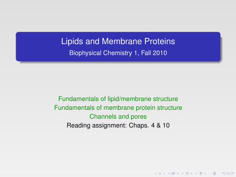
Back to the cell:
found. Eukaryotic cells are usually at least 10 times larger than prokaryotic cellsand more complex. In eukaryotic cells, the basic prokaryotic cell structure with theplasma membrane and cytoplasm is upgraded with compartments, also calledorganelles. In the cytoplasm, additional distinctive structures can be found. Insome cases their interior is segregated from each other by a membrane. The mostcommon organelles are: (i) the nucleus storing the cell genetic material and wherereplication and gene expression takes place; (ii) the cytosol, where protein syn-thesis and many essential biochemical reactions take place; (iii) the mitochon-drion, a power plant and energy storage compartment; (iv) the endoplasmaticreticulum and Golgi apparatus, where proteins are packaged and sent to furtherlocations; (v) the lysosomes or vacuoles, where polymeric macromolecules, suchas proteins, are degraded into usable monomers (Fig. 1.3).
It is believed that all organisms on Earth originate from a single kind of uni-cellular organism. Today many millions of different kinds of organisms that donot interbreed with one another can be found and we call them species. They areall successfully adapted to their different environments and in this sense, perfect.However, some of them may not be perfect tomorrow and can thereby become
4 � A Textbook of Structural Biology
FA
FIGURE 1.3 � A schematic picture of an animal cell showing sub-cellular structures, such asnucleus, membrane systems (ER), mitochondrion, etc. (Made by Michael W. Davidson, FloridaState University.)
b541_Chapter-01.qxd 11/20/2008 10:54 AM Page 4
Basic chemistry of lipids
4.3 Amphiphile Self-Assembly Into Different Aggregate Structures
4.3.1 Lipid Packing and Spontaneous Curvature
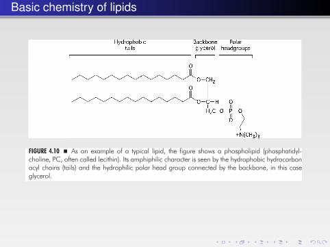
A typical lipid structure is shown in (Fig. 4.10). Since polar lipids are composed oftwo parts, a hydrophilic part and a hydrophobic part, connected by a backboneresidue, they are referred to as amphiphiles. In water, they assemble into differenttypes of aggregates that form phases.
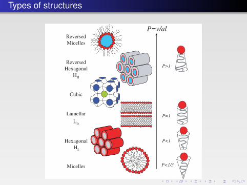
One of the most useful concepts for a qualitative understanding of the phasebehavior in amphiphilic systems is based on the geometry or general shape of alipid molecule (Fig. 4.11). The self-assembly of lipid molecules depends on adimensionless packing parameter defined by the ratio:
P = v/al
where v is the volume of the fluid hydrocarbon chains, l is the length of thehydrophobic chains and a is the optimal cross-sectional area of the polar headgroup as shown in Fig. 4.11.
When the packing parameter (sometimes also called the surfactant number) isequal to unity (cylindrical-like molecules, Fig. 4.12), the conditions are optimal forthe formation of a bilayer structure. If P > 1, the lipid molecules are wedge-shapedand the lipid monolayer prefers to curve towards the water region, i.e. it formsreversed micelles or an HII liquid crystalline phase (Fig. 4.12).
The Basics of Lipids and Membrane Structure � 135
FA
FIGURE 4.10 � As an example of a typical lipid, the figure shows a phospholipid (phosphatidyl-choline, PC, often called lecithin). Its amphiphilic character is seen by the hydrophobic hydrocarbonacyl chains (tails) and the hydrophilic polar head group connected by the backbone, in this caseglycerol.
b541_Chapter-04.qxd 11/20/2008 10:57 AM Page 135
Lipids self-assemble...124 � A Textbook of Structural Biology
FA
Reversed micelles
Micelles
Lipid bilayers
Liposomes or
vesicles
Lipid molecule
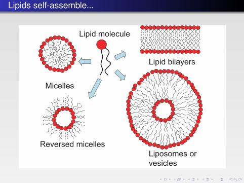
FIGURE 4.1 � A cartoon of four representative lipid aggregate structures. A lipid bilayer mayalso form a closed structure called a lipid vesicle or liposome. Note that these drawings onlyshow average geometrical structures. In reality, these structures are much more varied anddynamic.
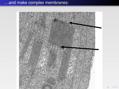
FIGURE 4.2 � Thylakoid membranes from a chloroplast illustrating the sharp bends (at thearrows) between the flat regions. Electron microscopy picture by C. Weibull provided byP.Å. Albertsson.
b541_Chapter-04.qxd 11/20/2008 10:57 AM Page 124
....and make complex membranes:
124 � A Textbook of Structural Biology
FA
Reversed micelles
Micelles
Lipid bilayers
Liposomes or
vesicles
Lipid molecule
FIGURE 4.1 � A cartoon of four representative lipid aggregate structures. A lipid bilayer mayalso form a closed structure called a lipid vesicle or liposome. Note that these drawings onlyshow average geometrical structures. In reality, these structures are much more varied anddynamic.
FIGURE 4.2 � Thylakoid membranes from a chloroplast illustrating the sharp bends (at thearrows) between the flat regions. Electron microscopy picture by C. Weibull provided byP.Å. Albertsson.
b541_Chapter-04.qxd 11/20/2008 10:57 AM Page 124
Controlling the amount of unsaturation
4.2.1.1 Phospholipids
As major constituents of biological membranes, phospholipids play a key role inall living cells. The two principal groups of phospholipids are the glycerophos-pholipids that contain glycerol, and the sphingophospholipids that contains thealcohol, sphingosine (Fig. 4.6).
A number of different polar head groups can be found in phospholipids, forexample, choline and ethanolamine that yield zwitterionic head groups at neutralpH, as well as negatively charged serine, glycerol and phosphate.
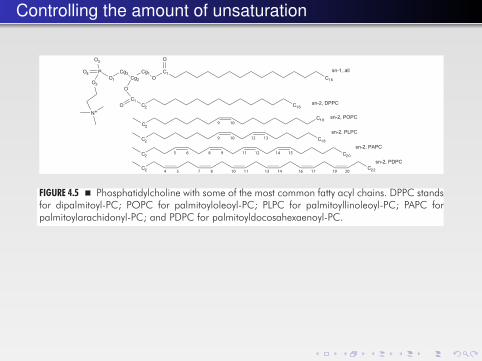
Phosphatidylcholines and related phospholipids usually contain a saturatedfatty acid in the sn-1 position but an unsaturated acid, which may contain betweenone to six double bonds, at sn-2. Hydrolysis of the ester linkage at sn-2 yields a1-acyl-3-phosphoglycerol, known as a lysophospholipid. It works like a powerfulsurfactant or detergent and leads to lysis of cells. Some snake venoms, for exam-ple, contain phospholipases that synthesize lysophosphatidylcholine.
128 � A Textbook of Structural Biology
FA
FIGURE 4.4 � A dipalmitoylphospholipid molecule where the chiral carbon on the glycerolmoiety is indicated.
C16
C1O
Cg1Cg2
Cg3O1
P
O
sn-1, all
sn-2, DPPC
sn-2, POPC
sn-2, PLPC
sn-2, PAPC
sn-2, PDPC
O3
O2
N+
O4
O
C1O C2
C2
C2
C2 C18
C2
C16
C20
C22
C189 10
9 10
5 6
4 5 7 8 10 11 13 14 16 17 19 20
8 9 11 12 14 15
12 13
FIGURE 4.5 � Phosphatidylcholine with some of the most common fatty acyl chains. DPPC standsfor dipalmitoyl-PC; POPC for palmitoyloleoyl-PC; PLPC for palmitoyllinoleoyl-PC; PAPC forpalmitoylarachidonyl-PC; and PDPC for palmitoyldocosahexaenoyl-PC.
b541_Chapter-04.qxd 11/20/2008 10:57 AM Page 128
Lipid phase diagrams
For three components at constant pressure, we have F = 4 – p, and it is nec-essary also to fix the temperature to be able to illustrate the phase diagram ona two-dimensional page. Therefore, for a three-component system we utilize atriangular diagram with the pure compounds in the corners of the triangle (notshown; see a textbook in physical chemistry). The maximum number of phasesin equilibrium is three, and a typical characteristic of the ternary phase dia-gram is the areas of three-phase triangles that occur as compared with thethree-phase lines present in the two-component systems.
In the construction of phase diagrams the so-called lever rule is very useful.A point in a two-phase region of a phase diagram (binary or ternary) indicatesnot only, qualitatively, that two phases are present but represents, quantita-tively, the relative amounts of each one. The relative amounts of the twophases that are in equilibrium are determined by the relative distances of theparticular point on its tie line from the respective phase boundaries — this iscalled the lever rule. For a binary system, tie lines are always horizontal, but fora ternary system, their directions are not always easily predicted, and theyhave to be determined experimentally. Here, the NMR method is particularly
132 � A Textbook of Structural Biology
FA
60
50
40
30
5 10 15 20H2O/DPPC mol/mol
t oC
Lα
Pβ’+Lα
Lβ’+Lα
Lβ’
Pβ’
Lβ’+Pβ’
Pβ’+H2O
Lβ’+H2O
Tm
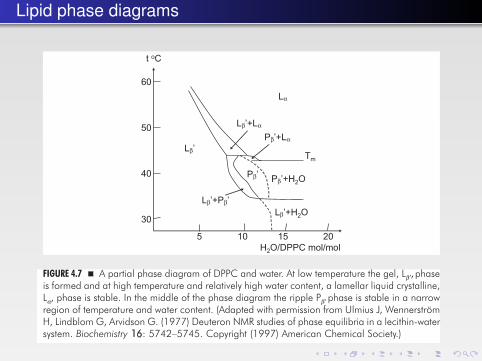
FIGURE 4.7 � A partial phase diagram of DPPC and water. At low temperature the gel, Lβ′, phaseis formed and at high temperature and relatively high water content, a lamellar liquid crystalline,Lα, phase is stable. In the middle of the phase diagram the ripple Pβ′ phase is stable in a narrowregion of temperature and water content. (Adapted with permission from Ulmius J, WennerströmH, Lindblom G, Arvidson G. (1977) Deuteron NMR studies of phase equilibria in a lecithin-watersystem. Biochemistry 16: 5742–5745. Copyright (1997) American Chemical Society.)
b541_Chapter-04.qxd 11/20/2008 10:57 AM Page 132
Types of structures
136 � A Textbook of Structural Biology
FA
l
Areaa
Volumev
FIGURE 4.11 � A schematic drawing of the shape of a lipid molecule forming spherical micellesas shown in Fig. 4.12. The red sphere is the polar headgroup and the hydrophobic tail is shownin gray. The components defining the packing parameter are indicated.
ReversedMicelles
ReversedHexagonal
HII
Cubic
Lamellar
Lα
HexagonalHI
Micelles
P=v/al
P>1
P=1
P<1/3
P<1
FIGURE 4.12 � Lipid molecules of different shapes and packing parameters. The possible aggre-gate structures in different phases (micellar solutions and liquid crystalline phases) are shown tothe left. A liquid crystalline phase has the properties of a liquid and at the same time shows along-range order as in a crystal.
This simple approach is very useful for explaining the kind of shapes certainmolecules assume. However, one has always to remember that the surface area amight have a complex dependence on temperature, charge, and concentration,and more sophisticated considerations may be needed. For example, a change in
b541_Chapter-04.qxd 11/20/2008 10:57 AM Page 136
Lamellar (membrane) phases have curvature
the molecular shape does not fully explain why a reversed hexagonal, HII, phaseis formed at high water content when an alkane or hydrophobic peptide is addedto seemingly stable lamellar liquid crystalline phases of phosphatidylcholine (PC),an apparently “cylindrical” lipid molecule. Obviously, this has to mean thateven the PC molecules in multilayers have a packing parameter that is slightlylarger than one, but other factors restrain them from forming a curved mono-layer. The reason is that it is not possible to pack the PC molecules in a largeHII cylinder without creating a large interstitial volume of vacuum as will bediscussed below.
Bilayers that are formed by such PC molecules are said to be “frustrated” (seebelow). This is explained by a concept known as lipid monolayer curvature that isrelated to the packing parameter but has a more general character not involvingthe lipid molecules specifically. The energy needed to deform a membraneis determined by the structure and elasticity of the membrane. The non-deformedunstressed state of the membrane is referred to as the spontaneous state. Deviati-ons from the spontaneous state, the forces required for these deviations, andthe accumulated energy in the new shape determine the membrane elasticproperties.
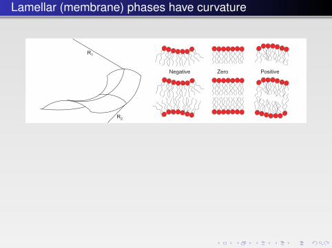
To understand this, let us briefly review the physical chemistry of mem-brane bending and the energetics involved. First, we need to look at some def-initions. At any point on a sheet in three-dimensional space, two principal radiiof curvature R1 and R2 and local curvatures c1 = 1/R1 and c2 = 1/R2 can bedefined (Fig. 4.13).
The sign of the curvature is arbitrary, and by convention one uses a definitionas shown in Fig. 4.13, where a region that bulges “outward” from the volumeenclosed from the surrounding medium has a positive curvature. Thus, sphericalmicelles have uniformly positive curvature, since R1 and R2 are both positive andequal. Saddle-shaped membranes, found, for example, on the bicontinuous cubicphase structure (illustrated in Fig. 4.15 below) or at the necks of budding vesicles,
The Basics of Lipids and Membrane Structure � 137
FA
R1
R2
Negative Zero Positive
FIGURE 4.13 � Left: The definition of the two radii of membrane curvature. In this case with asaddle-shaped surface the two radii have different signs. Right: Illustration of the definition ofthe sign of the radius of curvature (by convention).
b541_Chapter-04.qxd 11/20/2008 10:57 AM Page 137
Lipid packing and lateral pressureThe Basics of Lipids and Membrane Structure � 141
FA
Head group repulsion (π > 0)
Interfacial tension(π < 0)
Chain repulsions(entropic) (π > 0) z
Interfacial tensionHead group repulsion
0π(z)
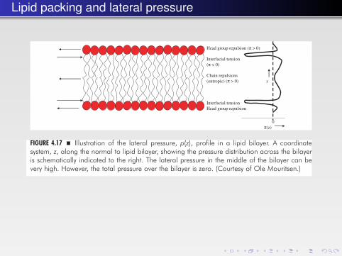
FIGURE 4.17 � Illustration of the lateral pressure, p(z), profile in a lipid bilayer. A coordinatesystem, z, along the normal to lipid bilayer, showing the pressure distribution across the bilayeris schematically indicated to the right. The lateral pressure in the middle of the bilayer can bevery high. However, the total pressure over the bilayer is zero. (Courtesy of Ole Mouritsen.)
FIGURE 4.18 � High lateral pressure, p(z), can result in a change in the conformation of an inte-gral membrane protein (striped or dashed) as illustrated by the cross-section A(z). The proteincan be in any of two states; r or t. γ is the interfacial tension. (Reprinted with permission fromCantor RS. (1997) Lateral pressures in cell membranes: a mechanism for modulation of proteinfunction. J Phys Chem B 101: 1723–1725. (Copyright (1997) ACS.))
b541_Chapter-04.qxd 11/20/2008 10:57 AM Page 141

Pressure and conformation
The Basics of Lipids and Membrane Structure � 141
FA
Head group repulsion (π > 0)
Interfacial tension(π < 0)
Chain repulsions(entropic) (π > 0) z
Interfacial tensionHead group repulsion
0π(z)
FIGURE 4.17 � Illustration of the lateral pressure, p(z), profile in a lipid bilayer. A coordinatesystem, z, along the normal to lipid bilayer, showing the pressure distribution across the bilayeris schematically indicated to the right. The lateral pressure in the middle of the bilayer can bevery high. However, the total pressure over the bilayer is zero. (Courtesy of Ole Mouritsen.)
FIGURE 4.18 � High lateral pressure, p(z), can result in a change in the conformation of an inte-gral membrane protein (striped or dashed) as illustrated by the cross-section A(z). The proteincan be in any of two states; r or t. γ is the interfacial tension. (Reprinted with permission fromCantor RS. (1997) Lateral pressures in cell membranes: a mechanism for modulation of proteinfunction. J Phys Chem B 101: 1723–1725. (Copyright (1997) ACS.))
b541_Chapter-04.qxd 11/20/2008 10:57 AM Page 141
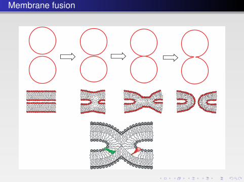
Membrane fusion
per unit area) needed to drive this fusion stage should be at least about 0.1kcal/mol/nm2.
4.4.4 Lipid Synthesizing EnzymesThe structure of fatty acid synthase is described in Sec. 5.4. The regulation of themembrane lipid composition implies that the activity of the enzymes synthesizingthe lipids (lipid synthases) is adjusted to the prevailing growth conditions of thecells. Some kind of signal(s), reflecting the status of the lipid bilayer, must thus betransferred from the bilayer to the lipid synthases. The lipid synthases are gener-ally more or less tightly associated to the lipid bilayer, and one possibility is thatthe activity of these enzymes is directly influenced by the properties of the lipidbilayer (see Fig. 4.26). Another possibility is that the synthase activity is regulated
152 � A Textbook of Structural Biology
FA
FIGURE 4.25 � Above. Steps in the fusion of membrane. The beginning and final stages are seenon the extremes, whereas two intermediates are seen in the middle. The third stage is where thestalk has been formed. The shapes of the lipids are of great importance for the formation of thestalk (compare the section about bilayer curvature). Below. A stalk structure proposed to occurin membrane fusion. The dashed lines show the bilayer midplane. A green-colored cone-shapedlipid molecule such as PE (on the left wing of the stalk) matches the stalk structure, whereas thered-colored inverted-cone-shaped lipid molecule such as LPC (on the right wing of stalk) disturbsthe packing of the lipids in the stalk.
b541_Chapter-04.qxd 11/20/2008 10:58 AM Page 152
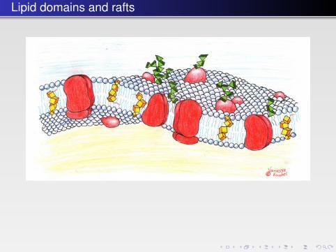
Lipid domains and rafts
of the membrane enzymes of A. laidlawii. The model suggests that the stored elas-tic energy of the lipid bilayer modifies the activity of curvature-sensitive enzymesthrough interaction with amphipathic α-helices. As their binding depends on thelipid composition, this results in a biophysical feedback mechanism for the regula-tion of the stored elastic energy that depends on the packing of the lipids in thebilayer. Thus, restrictions are imposed on the balance between lamellar- and non-lamellar-forming lipids in the plasma membrane and on the concentrations of par-ticular lipids. By using measured values of lipid curvatures from A. laidlawii, thetheoretical model gives quite a good, although as yet not fully quantitative,description of the membrane process.
4.4.5 Lipid Domains and Rafts in MembranesIn 1972, Singer and Nicolson launched their classical model of the membrane asa matrix in which the proteins have a degree of motional freedom in a lipid“sea.” This “fluid mosaic model” became the framework and benchmark for ourcurrent understanding of membrane bilayers and their physiological function(Fig. 4.27).
However, the homogeneous nature of the membrane proposed in this model,characterized by random distribution of molecular components in the membrane,has later been altered. Many recent studies have revealed that cell membranespossess a rather complex lateral organization. For example, it was discovered bysingle-particle tracking techniques, that labeled lipid or protein molecules per-form a lateral diffusive motion, and that they are temporarily confined into a cor-ral on the membrane.
154 � A Textbook of Structural Biology
FA
FIGURE 4.27 � A cartoon of the fluid mosaic model of a biological membrane from 1972according to Singer and Nicolson. The yellow transmembrane molecules represent cholesteroland the green parts sticking out into the solution represent sugar molecules. (Courtesy ofVanessa Kunkel.)
b541_Chapter-04.qxd 11/20/2008 10:58 AM Page 154
Basic classification scheme for membrane proteins
pores) facilitate passive transport from a higher to a lower concentration and can becoupled to advanced mechanisms of gating that control the opening and closureof the channel pathway across the membrane. Well-studied examples includeion-specific channels, porins and mechanosensitive channels. Receptors in manyvariations mediate a signal across the membrane and exploit the binding energyof a specific ligand (e.g. hormones, neurotransmitters or odorants) to stabilize thesignal-transmitting structure (see Chap. 11). Several receptors are gated channelslike the ionotropic glutamate receptors and voltage-gated potassium channels.
Membrane proteins are also major drug targets in pathophysiology. In cells themembranes normally constitute only a small fraction of the cell volume, andmembrane proteins are typically expressed at low levels compared to soluble pro-teins. At the same time membrane proteins are often difficult to stabilize outsideof a membrane and are therefore difficult to study. For these and other reasonsmembrane proteomics and structural information on membrane proteins haveonly slowly been emerging. However, with the advent of powerful synchrotronsources and well-developed computer programs in crystallography combinedwith an increasing knowledge of purification and crystallization, membrane pro-tein structures are now emerging at an increasing pace.
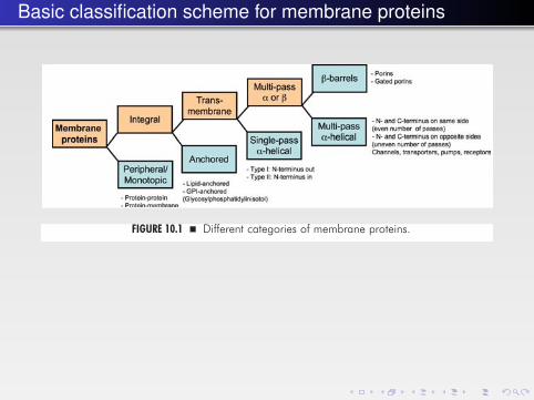
Some categories of membrane proteins are illustrated in Fig. 10.1. Peripheralmembrane proteins are associated with the membrane surface. Integral mem-brane proteins are either transmembrane proteins or proteins anchored to themembrane through lipid chains or glycophosphatidylinositol (GPI) moietiesattached to them. This chapter will discuss the structure and properties of trans-membrane proteins.
10.1.1 From Membranes to Integral Membrane ProteinsIn 1948 Benjamin Libet identified a membrane-bound enzyme — an ATPasefrom giant squid nerves. At this time there were also large breakthroughs in the
336 � A Textbook of Structural Biology
FA
FIGURE 10.1 � Different categories of membrane proteins.
b541_Chapter-10.qxd 1/2/2009 3:22 PM Page 336
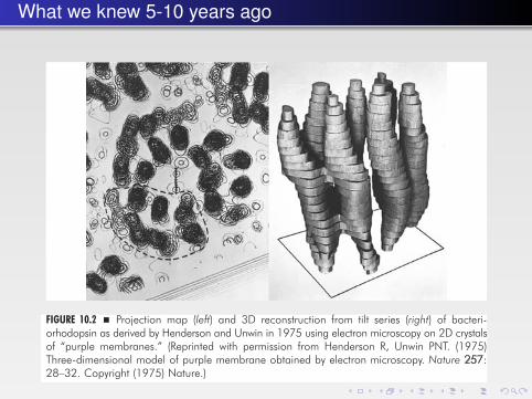
What we knew 5-10 years ago
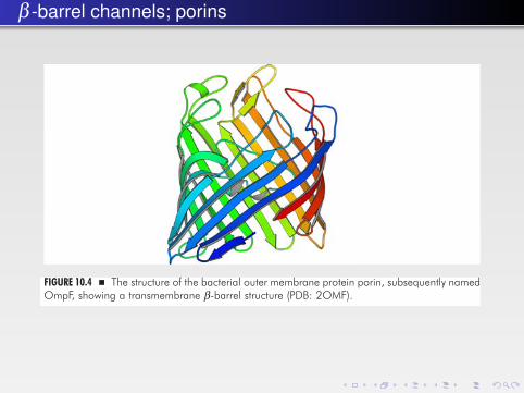
first crystallization of the photosynthetic reaction center from Rhodopseudomonasviridis — this soon turned out to be a very good move. Despite repeated failuresto obtain diffraction by X-rays, Michel succeeded after having obtained bettercrystals forms by changing detergents and testing micelle modulating addi-tives. In fact, most people at that time had considered his quest for a crystalstructure of a membrane protein to be rather impossible. The atomic structuredetermination of the photosynthetic reaction center with all its ligands andmetal centers revealed a new world of electron chains and transport pathwaysacross the membrane and close interactions with lipid molecules — a giganticachievement even by today’s standards — and Michel shared the Nobel prizewith his colleagues Deisenhofer and Huber in 1988 (Fig. 10.3). Three-dimensionalcrystals of the E. coli outer membrane protein porin (later termed OmpF)diffracting X-rays at medium resolution had been reported already in 1980, butit was not until 1992 that the structure of OmpF was determined, showing 16β-stands arranged in a large barrel embedded in the membrane as a very illus-trative representation of a transmembrane pore (Fig. 10.4; see also Chap. 2and App. C).
338 � A Textbook of Structural Biology
FA
FIGURE 10.2 � Projection map (left) and 3D reconstruction from tilt series (right) of bacteri-orhodopsin as derived by Henderson and Unwin in 1975 using electron microscopy on 2D crystalsof “purple membranes.” (Reprinted with permission from Henderson R, Unwin PNT. (1975)Three-dimensional model of purple membrane obtained by electron microscopy. Nature 257:28–32. Copyright (1975) Nature.)
b541_Chapter-10.qxd 1/2/2009 3:22 PM Page 338
Seven transmembrane helicesMembrane Proteins � 343
FA
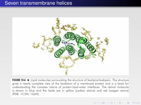
FIGURE 10.6 � Lipid molecules surrounding the structure of bacteriorhodopsin. The structuregives a nearly complete view of the lipidation of a membrane protein and is a basis forunderstanding the complex nature of protein-lipid-water interfaces. The retinal moleculeis shown in blue and the lipids are in yellow (carbon atoms) and red (oxygen atoms)(PDB: 1C3W, 1QJH).
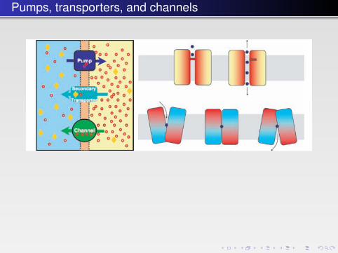
FIGURE 10.7 � Left: Schematic overview of transport mechanisms. Top: A primary transporter(a pump) establishes an electrochemical gradient for the red cation. Middle: A secondarytransporter exploiting the electrochemical gradient for active symport of the yellow solute(e.g. other ions, metabolites, sugar, neurotransmitters). Bottom: A channel allowing for thedownhill transport of the red cation with rates being limited by diffusion through the selec-tivity filter. Right: The different principles of gated channels and an active transporter.The transporter (bottom) is represented as an inverted dimer, providing a simple basis forthe design of inward and outward facing conformations. Combined with an energy sourcesuch as ATP hydrolysis or an electrochemical gradient, the transporter achieves a vectorialcomponent. The kinetics of channels and transporters are typically very different — limitedby diffusion rates versus large conformational changes, respectively.
b541_Chapter-10.qxd 1/2/2009 3:22 PM Page 343
The photosynthetic reaction center
10.2 The α-Helix and β-Barrel Membrane Protein Structures
The first membrane protein structures — bacteriorhodopsin (see Sec. 10.5.1), thephotosynthetic reaction center (Fig. 10.3) and porin/OmpF (Fig. 10.4) — revealedthat there are two fundamentally different classes of membrane proteins: α-helixand β-barrel proteins. These two frameworks fulfill a fundamental requirement:minimizing the energy cost of localization of protein structure to the hydrophobicenvironment of the membrane as compared to aqueous environments. Thepolypeptide backbone has a hydrogen-bonding potential at the carbonyl andamide positions. This potential is satisfied in a systematic way in the membraneby β-barrels or α-helices generating the hydrogen bonds through intramolecularinteractions (see Chap. 2). At the same time, these two frameworks are very
Membrane Proteins � 339
FA
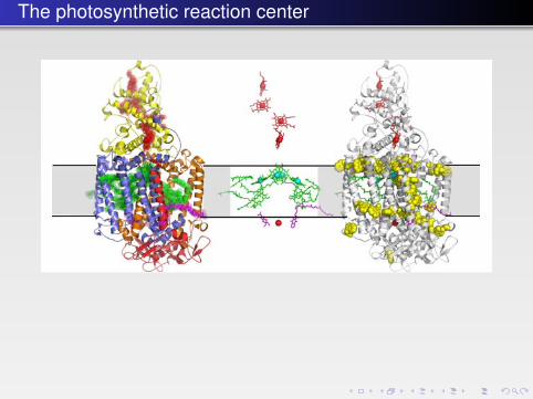
FIGURE 10.3 � The first atomic structure of a complex membrane protein — the photosyntheticreaction center from R. viridis. Left: A cartoon representation. The cytochrome subunit C isshown in yellow, the transmembrane subunits L and M in orange and blue respectively, and thecytoplasmic H subunit (with a single transmembrane helix) in red. The electron-conductingligands are indicated by semitransparent spheres with heme groups in the C subunit in red,bacteriochlorophylls and bacteriopheophytins in green, and quinones in magenta (PDB: 1PRC).There is a pseudosymmetry between the L and M subunits relating also the ligands starting fromthe “special pair” of chlorophylls at the center and dividing into two branches. Middle:The same structure showing just the ligands in stick representation with magnesium and iron ionsindicated by cyan and red spheres, respectively. Right: The same structure showing the distributionof tryptophan residues (yellow) in the membrane-spanning subunits, depicting clearly the mem-brane interface. The shaded gray area indicates the approximate position of the membrane.
b541_Chapter-10.qxd 1/2/2009 3:22 PM Page 339
Pumps, transporters, and channels
Membrane Proteins � 343
FA
FIGURE 10.6 � Lipid molecules surrounding the structure of bacteriorhodopsin. The structuregives a nearly complete view of the lipidation of a membrane protein and is a basis forunderstanding the complex nature of protein-lipid-water interfaces. The retinal moleculeis shown in blue and the lipids are in yellow (carbon atoms) and red (oxygen atoms)(PDB: 1C3W, 1QJH).
FIGURE 10.7 � Left: Schematic overview of transport mechanisms. Top: A primary transporter(a pump) establishes an electrochemical gradient for the red cation. Middle: A secondarytransporter exploiting the electrochemical gradient for active symport of the yellow solute(e.g. other ions, metabolites, sugar, neurotransmitters). Bottom: A channel allowing for thedownhill transport of the red cation with rates being limited by diffusion through the selec-tivity filter. Right: The different principles of gated channels and an active transporter.The transporter (bottom) is represented as an inverted dimer, providing a simple basis forthe design of inward and outward facing conformations. Combined with an energy sourcesuch as ATP hydrolysis or an electrochemical gradient, the transporter achieves a vectorialcomponent. The kinetics of channels and transporters are typically very different — limitedby diffusion rates versus large conformational changes, respectively.
b541_Chapter-10.qxd 1/2/2009 3:22 PM Page 343
Some nomenclature
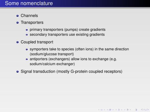
Channels
Transporters
primary transporters (pumps) create gradientssecondary transporters use existing gradients
Coupled transport
symporters take to species (often ions) in the same direction(sodium/glucose transport)antiporters (exchangers) allow ions to exchange (e.g.sodium/calcium exchanger)
Signal transduction (mostly G-protein coupled receptors)
β -barrel channels; porins
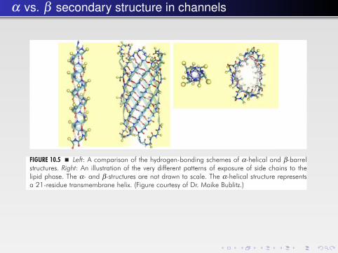
different: β-barrels are defined by “long-range” hydrogen bonds between indi-vidual strands that leave little room for conformational changes while keeping thehydrogen bonds intact; in contrast, α-helices form local (n + 4) hydrogen bondsthat allow for conformational changes in the helix configurations across the mem-brane to be exploited (Fig. 10.5). Indeed, β-barrel proteins mostly serve as poresfor passive transport across the membrane while more advanced transmembranemodules, like ion channels and transporters, are based on α-helical structures.
340 � A Textbook of Structural Biology
FA
FIGURE 10.4 � The structure of the bacterial outer membrane protein porin, subsequently namedOmpF, showing a transmembrane β-barrel structure (PDB: 2OMF).
FIGURE 10.5 � Left: A comparison of the hydrogen-bonding schemes of α-helical and β-barrelstructures. Right: An illustration of the very different patterns of exposure of side chains to thelipid phase. The α- and β-structures are not drawn to scale. The α-helical structure representsa 21-residue transmembrane helix. (Figure courtesy of Dr. Maike Bublitz.)
b541_Chapter-10.qxd 1/2/2009 3:22 PM Page 340
The iron-citrate outer membrane transporter
β-barrel proteins are also responsible for the pathogenicity of some bacteriaand viruses in their strategy for invasion/spreading or foraging through pene-tration of the host cell membrane by a self-assembling pore. A well-studiedexample is the α-hemolysin pore, which forms by oligomerization of the solubleα-hemolysin monomer at the host cell membrane. In fact, this mechanism resem-bles one of the key constituents of the innate immune system, the membraneattack complex, which assembles as a large transmembrane pore at the membraneof pathogens or other foreign cells (e.g. of the tissues of a transplanted organ) bycomplex formation of complement factors C5b and C6, C7, and C8 along withseveral copies of the C9 factor.
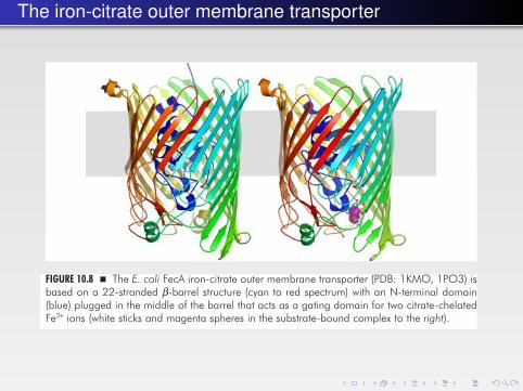
Many porins, for example OmpC, OmpF and PhoE, are pores of the outermembrane of Gram-negative bacteria. They do not bind their substrates with anysignificant affinity. They allow the passage of small polar substances (< 600 Da)driven by their concentration gradients. For substances present at low concentra-tions passive diffusion is not sufficient. Such substances are transported throughsubstrate-specific channels such as LamB, which is selective for maltose, PhoE, whichis in turn selective for phosphate, and FecA (Fig. 10.8), which imports ferric citrate.
10.4.1.2 The water channel aquaporin
Water can diffuse through membranes. However, this is too inefficient to meet thephysiological needs of many cells. Therefore, the existence of water channels was
Membrane Proteins � 345
FA
FIGURE 10.8 � The E. coli FecA iron-citrate outer membrane transporter (PDB: 1KMO, 1PO3) isbased on a 22-stranded β-barrel structure (cyan to red spectrum) with an N-terminal domain(blue) plugged in the middle of the barrel that acts as a gating domain for two citrate-chelatedFe3+ ions (white sticks and magenta spheres in the substrate-bound complex to the right).
b541_Chapter-10.qxd 1/2/2009 3:22 PM Page 345
α vs. β secondary structure in channels
different: β-barrels are defined by “long-range” hydrogen bonds between indi-vidual strands that leave little room for conformational changes while keeping thehydrogen bonds intact; in contrast, α-helices form local (n + 4) hydrogen bondsthat allow for conformational changes in the helix configurations across the mem-brane to be exploited (Fig. 10.5). Indeed, β-barrel proteins mostly serve as poresfor passive transport across the membrane while more advanced transmembranemodules, like ion channels and transporters, are based on α-helical structures.
340 � A Textbook of Structural Biology
FA
FIGURE 10.4 � The structure of the bacterial outer membrane protein porin, subsequently namedOmpF, showing a transmembrane β-barrel structure (PDB: 2OMF).
FIGURE 10.5 � Left: A comparison of the hydrogen-bonding schemes of α-helical and β-barrelstructures. Right: An illustration of the very different patterns of exposure of side chains to thelipid phase. The α- and β-structures are not drawn to scale. The α-helical structure representsa 21-residue transmembrane helix. (Figure courtesy of Dr. Maike Bublitz.)
b541_Chapter-10.qxd 1/2/2009 3:22 PM Page 340
The aquaporin channel
predicted long ago and discovered in the early 1990s by Peter Agre. These chan-nels are called aquaporins and are abundant proteins of many related types. Manycells have these membrane channels with specificity for water molecules. Withinthe family there are proteins that are also permeable to glycerol. Aquaporin solvesa case of a difficult selectivity problem: how can the passage of small ions orprotons be avoided while permitting water to pass?
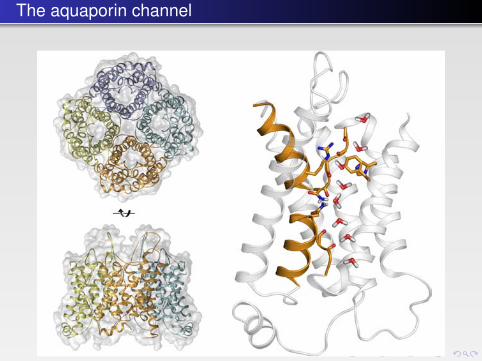
The aquaporins are tetramers, where the pores go through each subunit. Theprotein is composed of six transmembrane helices and two shorter helices that“meet” at the center of the membrane (Fig. 10.9). The N- and C-terminal halvesseem to have originated through a gene duplication and are related by an approx-imate two-fold axis in the plane of the membrane. The channel has an hourglassstructure with two vestibules connected by a 20 Å long channel, which at itsnarrowest point is no more than 2.8 Å wide. Water molecules have to travelthrough this channel in a single file. Two loops are symmetry-related and containa highly conserved signature motif, NPA, which is situated at the channel with thetwo NPA sequences juxtaposed.
346 � A Textbook of Structural Biology
FA
FIGURE 10.9 � The aquaporin tetramer (left, top and bottom) has one pore in each monomer(PDB: 1J4N). Right: The aquaporin monomer as viewed parallel to the membrane surface. Themolecule has an approximate two-fold symmetry with the axis located horizontally in the centerof the figure and parallel to the plane of the paper. The asparagines of the conserved NPA motifsare shown as well as the arginine restricting passage of hydronium ions. The file of water mole-cules changing orientation is derived from Molecular Dynamics Studies.
b541_Chapter-10.qxd 1/2/2009 3:22 PM Page 346
The KcsA potassium channel348 � A Textbook of Structural Biology
FA
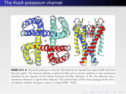
FIGURE 10.10 � The KcsA potassium channel. The tetramer as viewed from above (left) and fromthe side (right). The tetramer defines a selectivity filter and a central vestibule in the membranestabilized by the dipoles of the helices forming the filter. Because of this, the effective trans-membrane distance is significantly reduced. The conformation of the lower passage of the chan-nel defines whether the gate is open or closed (PDB: 1K4C).
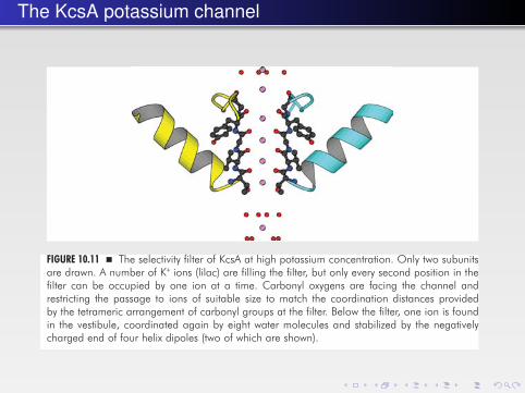
FIGURE 10.11 � The selectivity filter of KcsA at high potassium concentration. Only two subunitsare drawn. A number of K+ ions (lilac) are filling the filter, but only every second position in thefilter can be occupied by one ion at a time. Carbonyl oxygens are facing the channel andrestricting the passage to ions of suitable size to match the coordination distances providedby the tetrameric arrangement of carbonyl groups at the filter. Below the filter, one ion is foundin the vestibule, coordinated again by eight water molecules and stabilized by the negativelycharged end of four helix dipoles (two of which are shown).
b541_Chapter-10.qxd 1/2/2009 3:22 PM Page 348
The KcsA potassium channel
348 � A Textbook of Structural Biology
FA
FIGURE 10.10 � The KcsA potassium channel. The tetramer as viewed from above (left) and fromthe side (right). The tetramer defines a selectivity filter and a central vestibule in the membranestabilized by the dipoles of the helices forming the filter. Because of this, the effective trans-membrane distance is significantly reduced. The conformation of the lower passage of the chan-nel defines whether the gate is open or closed (PDB: 1K4C).
FIGURE 10.11 � The selectivity filter of KcsA at high potassium concentration. Only two subunitsare drawn. A number of K+ ions (lilac) are filling the filter, but only every second position in thefilter can be occupied by one ion at a time. Carbonyl oxygens are facing the channel andrestricting the passage to ions of suitable size to match the coordination distances providedby the tetrameric arrangement of carbonyl groups at the filter. Below the filter, one ion is foundin the vestibule, coordinated again by eight water molecules and stabilized by the negativelycharged end of four helix dipoles (two of which are shown).
b541_Chapter-10.qxd 1/2/2009 3:22 PM Page 348
The leucine transporter
substrate and one of the sodium ions. The different conformational states havenot been experimentally explored, but the discontinuous helices could be part ofthe structural changes.
10.6.2 Antiporters
Many antiporters are involved in exchanging ions across the cytoplasmic mem-brane. In bacteria one antiporter extrudes sodium or lithium in exchange for pro-tons. A gradient of H+ ions is the driving force to establish an electrochemicalpotential of Na+ across the membrane. In turn the Na+ gradient is used for differ-ent processes such as to drive flagellar rotation. The first insight into the structuresof antiporters comes from an E. coli protein called NhaA.
10.6.2.1 NhaA antiporter
NhaA is an Na+/H+ antiporter. It is activated at pH 6.5–8.5 and regulated by pH.NhaA is a dimer that is also built of 12 transmembrane helices (Fig. 10.25). TheN- and C-termini are on the cytoplasmic side. They are arranged in a uniqueway and not related to the NSS family of symporters. Nevertheless, part of themolecule has a two-fold symmetry parallel with the membrane. This includeshelices III, IV and V, which are symmetry related to X, XI and XII.
364 � A Textbook of Structural Biology
FA
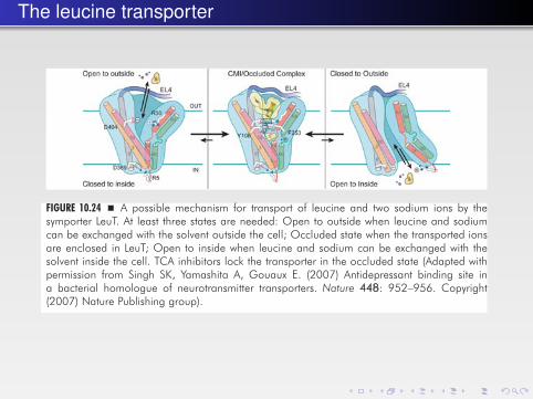
FIGURE 10.24 � A possible mechanism for transport of leucine and two sodium ions by thesymporter LeuT. At least three states are needed: Open to outside when leucine and sodiumcan be exchanged with the solvent outside the cell; Occluded state when the transported ionsare enclosed in LeuT; Open to inside when leucine and sodium can be exchanged with thesolvent inside the cell. TCA inhibitors lock the transporter in the occluded state (Adapted withpermission from Singh SK, Yamashita A, Gouaux E. (2007) Antidepressant binding site ina bacterial homologue of neurotransmitter transporters. Nature 448: 952–956. Copyright(2007) Nature Publishing group).
b541_Chapter-10.qxd 1/2/2009 3:22 PM Page 364
Bacteriorhodopsin: light signaling
the extracellular environment per photoisomerization cycle is therefore in place.This mechanism — a proton-conducting pathway including titratable Asp andGlu residues modulated in pKa value by an Arg residue — occurs in manyproton-pumping systems.
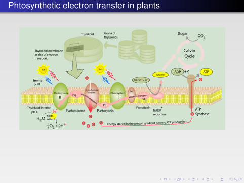
10.5.2 Light-Driven Redox Processes — The PhotosystemsThe ultimate power supply of the contemporary biosphere is the sun, and the abil-ity to extract the solar energy and split water to oxygen was a major turning pointin evolution when the atmosphere gradually turned into an oxidizing environ-ment. Photosynthesis extracts an estimated 100 Terawatts, corresponding to asmuch as about 0.1% of the total solar energy influx on earth. Through photosyn-thesis plants and microorganisms fixate CO2 from the atmosphere to build upglucose.
Photosynthesis is based on two photosystems, I (Fig. 10.18) and II, with absorp-tion maxima at 700 and 680 nm, respectively. Absorption is based on electron exci-tation and charge separation stabilized by a “special pair,” a set of two chlorophyllrings, each “hard-wired” by an electron transfer chain to the electron acceptor.In photosystem II this is a water-splitting manganese center producing oxygen.
The reaction is in fact far more complicated and involves a range of electron-transfer reactions that transform the highly activated reduction potential of
Membrane Proteins � 355
FA
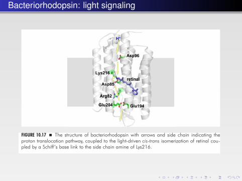
FIGURE 10.17 � The structure of bacteriorhodopsin with arrows and side chain indicating theproton translocation pathway, coupled to the light-driven cis-trans isomerization of retinal cou-pled by a Schiff’s base link to the side chain amine of Lys216.
b541_Chapter-10.qxd 1/2/2009 3:22 PM Page 355

The photosynthetic reaction center
10.2 The α-Helix and β-Barrel Membrane Protein Structures
The first membrane protein structures — bacteriorhodopsin (see Sec. 10.5.1), thephotosynthetic reaction center (Fig. 10.3) and porin/OmpF (Fig. 10.4) — revealedthat there are two fundamentally different classes of membrane proteins: α-helixand β-barrel proteins. These two frameworks fulfill a fundamental requirement:minimizing the energy cost of localization of protein structure to the hydrophobicenvironment of the membrane as compared to aqueous environments. Thepolypeptide backbone has a hydrogen-bonding potential at the carbonyl andamide positions. This potential is satisfied in a systematic way in the membraneby β-barrels or α-helices generating the hydrogen bonds through intramolecularinteractions (see Chap. 2). At the same time, these two frameworks are very
Membrane Proteins � 339
FA
FIGURE 10.3 � The first atomic structure of a complex membrane protein — the photosyntheticreaction center from R. viridis. Left: A cartoon representation. The cytochrome subunit C isshown in yellow, the transmembrane subunits L and M in orange and blue respectively, and thecytoplasmic H subunit (with a single transmembrane helix) in red. The electron-conductingligands are indicated by semitransparent spheres with heme groups in the C subunit in red,bacteriochlorophylls and bacteriopheophytins in green, and quinones in magenta (PDB: 1PRC).There is a pseudosymmetry between the L and M subunits relating also the ligands starting fromthe “special pair” of chlorophylls at the center and dividing into two branches. Middle:The same structure showing just the ligands in stick representation with magnesium and iron ionsindicated by cyan and red spheres, respectively. Right: The same structure showing the distributionof tryptophan residues (yellow) in the membrane-spanning subunits, depicting clearly the mem-brane interface. The shaded gray area indicates the approximate position of the membrane.
b541_Chapter-10.qxd 1/2/2009 3:22 PM Page 339
The photosynthetic reaction center
photo-excited electrons to the reduction of water to free oxygen while generatingproton gradients.
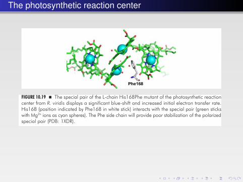
Insight has been obtained on how the optimum wavelength for photoabsorp-tion at the special pair is tuned (Fig. 10.19). By mutagenesis of the R. viridis pho-tosynthetic reaction center on the L-chain His168 position to Phe, a significantblue-shift and increase in the initial electron transfer rate were observed. TheHis168 residue plays a pivotal role as hydrogen bond donor to the special pair,which then becomes stabilized in polarized forms. Replacing His for a Pheresidue, the stabilization of a polarized form of the special pair is diminished, thusdemanding a higher energy for excitation.
10.5.3 ATP-driven Pumps, P-ATPases
Cation pumps of the P-ATPase family form electrochemical gradients across bio-membranes and maintain the homeostasis of cation levels and osmotic control inthe cell. They transform chemical energy of ATP to electrochemical potential in theform of cation gradients and eventually membrane potential. Members includeNa+, K+-ATPase, H+, K+-ATPase and Ca2+-ATPases, which are all of key importancein physiology. It is worth noting that the P-type ATPases account for approxi-mately one third of the ATP turnover in the body. However, plasma membranesof fungi and plants are also energized by a P-ATPase, the H+-ATPase forming astrong potential and steep pH gradients that drive the uptake of nutrients fromthe acidified medium. Skou characterized the Na+, K+-ATPase as the first member
Membrane Proteins � 357
FA
FIGURE 10.19 � The special pair of the L-chain His168Phe mutant of the photosynthetic reactioncenter from R. viridis displays a significant blue-shift and increased initial electron transfer rate.His168 (position indicated by Phe168 in white stick) interacts with the special pair (green stickswith Mg2+ ions as cyan spheres). The Phe side chain will provide poor stabilization of the polarizedspecial pair (PDB: 1XDR).
b541_Chapter-10.qxd 1/2/2009 3:22 PM Page 357
Phtosynthetic electron transfer in plants
Getting more complex: photosystem I356 � A Textbook of Structural Biology
FA
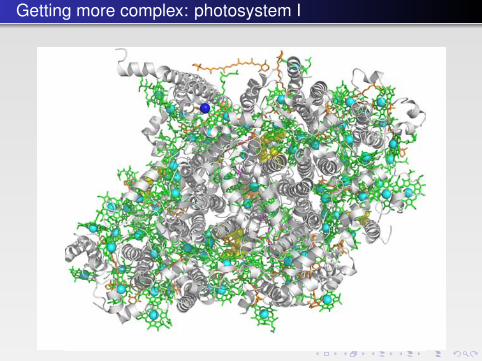
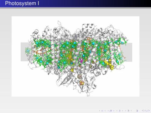
FIGURE 10.18 � Structure of photosystem 1 as seen from the thylakoid lumen onto the membrane(top) and from the side in the plane of the thylakoid membrane (bottom). This is only a monomerof the trimeric protein. There are 12 protein subunits, of which two (called A and B) have11 membrane-spanning helices and form the core of the protein. The monomer binds96 chlorophylls, three Fe4S4 iron-sulfur clusters, two phylloquinones, 22 carotenoids and fourlipid molecules. The protein subunits are indicated by the white cartoon, and ligands by stick orsphere representation with chlorophylls in green (with Mg2+ ions in cyan), β-carotene in orange,lipids in yellow, phylloquinones in magenta, Fe4S4 clusters as orange and yellow spheres, andCa2+ in blue. Note the pseudosymmetry around the special pair (center of top panel) andthe involvement of deeply buried lipid molecules as cofactors. This structure represents themost complete view of a large antenna-system for direction of excited electrons to an electrontransport chain providing charge separation and the establishment of potent redox equivalents(PDB: 1JB0).
b541_Chapter-10.qxd 1/2/2009 3:22 PM Page 356
Photosystem I
356 � A Textbook of Structural Biology
FA
FIGURE 10.18 � Structure of photosystem 1 as seen from the thylakoid lumen onto the membrane(top) and from the side in the plane of the thylakoid membrane (bottom). This is only a monomerof the trimeric protein. There are 12 protein subunits, of which two (called A and B) have11 membrane-spanning helices and form the core of the protein. The monomer binds96 chlorophylls, three Fe4S4 iron-sulfur clusters, two phylloquinones, 22 carotenoids and fourlipid molecules. The protein subunits are indicated by the white cartoon, and ligands by stick orsphere representation with chlorophylls in green (with Mg2+ ions in cyan), β-carotene in orange,lipids in yellow, phylloquinones in magenta, Fe4S4 clusters as orange and yellow spheres, andCa2+ in blue. Note the pseudosymmetry around the special pair (center of top panel) andthe involvement of deeply buried lipid molecules as cofactors. This structure represents themost complete view of a large antenna-system for direction of excited electrons to an electrontransport chain providing charge separation and the establishment of potent redox equivalents(PDB: 1JB0).
b541_Chapter-10.qxd 1/2/2009 3:22 PM Page 356
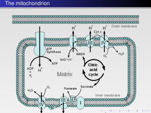
The mitochondrion
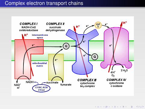
Complex electron transport chains