Embed Size (px)
Citation preview

Liquefaction Technologies for Producing Biocrude for Jet, Diesel and GasolineJOHN HOLLADAY
May 6, 2014 1
Energy and Environment DirectorateNorthwest Wood-Based Biofuels + Co-Products Conference, April 29, 2014

PNNL bioenergy researchDirect Liquefaction of Biomass
Producing catalysts and processes to make fuels directly from whole biomass (wet or dry)
Conversion of sugars and lignin
Producing new processes that make building blocks that are converted to chemicals and fuels
Refinery Integration
Developing solutions for co-processing biomass with fossil resources in existing infrastructure
CatalysisApplying fundamental and applied approaches to produce stable, active and selective catalysts able to operate in hih water environments
Fungal BiotechnologyImproving microbes for producing fuel and chemical precursors from complex sugars -integrating processes with catalysis
Advanced AnalysisAddressing site-specific constraints through high resolution geographical info-physical models, processes economic and life cycle analysis
Nat
iona
l Im
pact
Direct Liquefaction of Biomass
Producing catalysis and processes to make fuels directly from whole biomass (wet or dry)
Conversion of sugars and lignin
Producing new processes that make building blocks that are converted to chemicals and fuels
Refinery Integration
Developing solutions for co-processing biomass with fossil resources in existing infrastructure
CatalysisApplying fundamental and applied approaches to produce stable, active and selective catalysts able to operate in high water environments
Fungal BiotechnologyImproving microbes for producing fuel and chemical precursors from complex sugars -integrating processes with catalysis
Advanced AnalysisAddressing site-specific constraints through high resolution geographical info-physical models, processes economic and life cycle analysis
Capa
bilit
ies
Deliver Science & Technology to ensure sustainable incorporation of renewables into the fuel and chemical infrastructure

~1.4 ml 8-reactor packed bed system
40 ml dual T zone packed bed reactor
400 ml dual T zone packed bed reactors
1 L ebullated bed reactor 24 L 8-zone furnace packed bed reactor
Catalyst R&D at PNNL at different scales
3/40

Pyrolysis central challenge: Catalysis
Potential for distributed bio-oil production with processing in
central facility
Pyrolysis and Liquefaction Are multiple variants Yield depends on quality of
biomass feedstock and variant of technology
Primary need for all variants is improved catalysis
Produce hydrocarbon fuels from low quality bio-oil, but…
• Catalyst life is too short• Catalyst rate is too slow 4

Fuel characteristics
Desired CharacteristicsMiscible with petroleum-based fuels and transportable in current pipelinesMeet performance & storability criteria designed for jet engines—it must be jet fuel
5

Pyrolysis enables 100% renewable jet
May 6, 2014 6
The hydroplane ran on 98% Bio-SPK and 2% renewable aromaticsJet A1Spec
Starting SPK
Woody Pyrolysis Oil Aromatics-SPK
Freeze Point (oC) -47 -63 -53Flash Point (oC) 39 42 52Density (g/mL) 0.775 0.753 0.863

S, N, O containing Compounds < 5%
Paraffins70 - 85%
Aromatic< 25%
Olefins< 5%
Compound classes in jet fuels
May 6, 2014 7
Ideal Carbon Length C8-C16
Normal Paraffins Iso-paraffins Cyclic Paraffins
H3CCH3
CH3CH3
H3CCH3
H3CCH3
CH3
CH3
S
H3C CH3
CH3
OH
OH
O
We desire fuels with composition similar to above(i.e. a replacement or “drop-in” fuel)

Fast Pyrolysis and upgrading to fuels economics – 2009 estimate
Design Case Originally developed in 2009
Process appears viableResearch needs identifiedCatalyst maintenance appeared to have biggest impact initiallySet research targets for out years
8

Fast pyrolysis and upgrading to fuels economics – 2009
Conversion costs – Integration of experimental results with
modeled costs
Reduced the catalyst
replacement rate
Costs to be completely
updated Fall 2013
Modest yield increase
9

Fast pyrolysis and upgrading to fuels economics – 2013 Update
Sensitivity Analysis - $/gallon change from base case
10

May 6, 2014 11
Deactivation of RuSX/C leads to unstable material, which forms “char” resulting in reactor plugging in < 100 hCoMoSX/C also exhibits limitations to its catalyst life and deactivation occurs over <100 h campaign
Challenges for upgrading: reactor stability
Elliott et al Energy Fuels 2012, 26, 3869
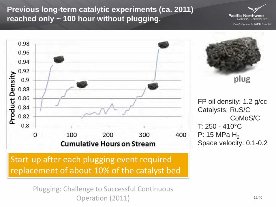
Previous long-term catalytic experiments (ca. 2011) reached only ~ 100 hour without plugging.
• FP oil density: 1.2 g/cc• Catalysts: RuS/C
CoMoS/C• T: 250 - 410°C• P: 15 MPa H2 • Space velocity: 0.1-0.2
plug
Plugging: Challenge to Successful Continuous Operation (2011)
Start-up after each plugging event required replacement of about 10% of the catalyst bed
12/40
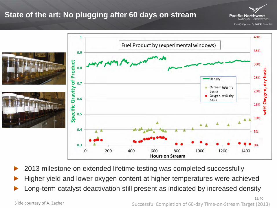
State of the art: No plugging after 60 days on stream
2013 milestone on extended lifetime testing was completed successfullyHigher yield and lower oxygen content at higher temperatures were achievedLong-term catalyst deactivation still present as indicated by increased density
Slide courtesy of A. Zacher Successful Completion of 60-day Time-on-Stream Target (2013)13/40

Sustainability pyrolysis oil with upgrading
Life cycle GHGs for gasoline from fast pyrolysis and upgrading
34.2 32.835.2 34.6
0
20
40
60
80
100
120
140
0
5
10
15
20
25
30
35
40
2011 SOT 2012 SOT 2013-14 2017
Tota
l Fue
l Yie
ld, g
al/d
ry to
n
g C
O2-
e/M
J ga
solin
e
End Use
Fuel Distribution
Conversion
FeedstockPreprocessingFeedstock Transportand HandlingFeedstock Production
Fuel Yield
63%Reduction 62%
Reduction63%
Reduction
65%Reduction
• 2017 goal case assumes better yields and economics, but has slightly higher GHGs• Higher yields lower feedstock contribution but increase conversion contribution• Preliminary indications are that fuel derived from fast pyrolysis of wood and bio-oil upgrading
appears to be >60% GHG reduction (cellulosic biofuel), however, qualification under the RFS is determined by the EPA
14
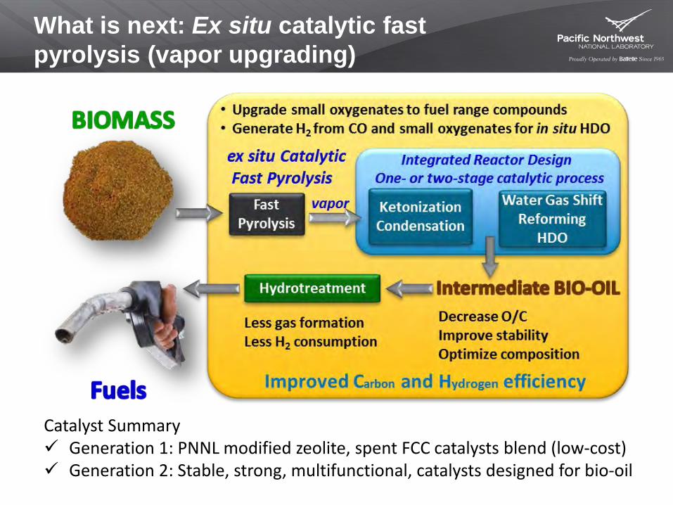
What is next: Ex situ catalytic fast pyrolysis (vapor upgrading)
Catalyst Summary Generation 1: PNNL modified zeolite, spent FCC catalysts blend (low-cost) Generation 2: Stable, strong, multifunctional, catalysts designed for bio-oil

Co-processing bio-oil with petroleum FCC oils (vacuum gas-oils)
Understand minimum upgrading of bio-oil for co-processingDevelop FCC catalysts tuned for bio-oil VGO mixturesUnderstand quality of productDetermine fate of biogenic carbon in the process
Tesoro Refinery, Anacortes, WA (Scott Butner, PNNL)

Hydrothermal liquefaction for improved oil
May 6, 2014 17
Hydrothermal Liquefaction • Feed: whole biomass + buffer
(10 to 20 wt% solids) • Operation: condensed phase • Bio-oil: gravity separable;
(oxygen: 10 to 20 wt%)• Product yield: ~50%-carbon; 32%-
mass
Bio-oil Upgrading• Operation: feed is thermally
stable, low H2 required• Yield: 94%-carbon; 84%-mass;
95%-volume• Product: high yield to distillate
range
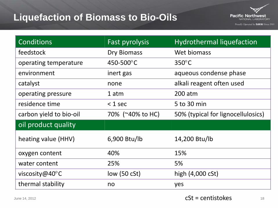
Liquefaction of Biomass to Bio-Oils
Conditions Fast pyrolysis Hydrothermal liquefactionfeedstock Dry Biomass Wet biomassoperating temperature 450-500°C 350°Cenvironment inert gas aqueous condense phase catalyst none alkali reagent often usedoperating pressure 1 atm 200 atmresidence time < 1 sec 5 to 30 mincarbon yield to bio-oil 70% (~40% to HC) 50% (typical for lignocellulosics)oil product quality
heating value (HHV) 6,900 Btu/lb 14,200 Btu/lb
oxygen content 40% 15%water content 25% 5%viscosity@40°C low (50 cSt) high (4,000 cSt)thermal stability no yes
June 14, 2012 18cSt = centistokes

PNNL HTL hybrid reactor (plug flow)
Small CSTR at critical temperature transition 19

HTL bio-oil quality
130 h on-stream, 7 L bio-oilMean balance: Wood 99% (Mass) and 88% (carbon)Mean balance: Cornstover 96% (Mass) and 83% (carbon)Lower yield to bio-oil from corn stover observed
Pine Corn Stover
Oxygen (Dry) 12% 17%Nitrogen 0.29% 1.1%
Sulfur 0.01% 0.04%Moisture 9% 8%
Density, g/ml 1.11 1.10Viscosity, cSt, 40°C 3100 3400Oil TAN mgKOH/g 55 44
20

Simulated distillation data (fuel quality)
May 6, 2014 21
Diesel Standard
Partner Stage 2
PNNL Stage 1PNNL Stage 2
Product composition 7% paraffin 47% cycloparaffin 46% aromatic
Shift the product to the distillate range

Carbon efficiency achieved
Step Carbon Efficiency
HTL 62%
Hydrotreat 96%
Combined 60%
HTL Reactor
Sepa
ratio
n
Filte
r
Hyd
rotr
eato
r
Feed Prep
Sepa
ratio
n
Aqueous Product(water created + organics)
Solids3 g
Gas10 g
H21 g
HydrocarbonProduct 30 g(60% of C)
Gas1 g
Aqueous 5 gBio-oil
35 g (62% of C)
Basis: 100 g Woody Biomass
Purge: 52 g (27% of C)
Recycle
22

Technoeconomic considerations
$0.00
$0.50
$1.00
$1.50
$2.00
$2.50
$3.00
$3.50
$4.00
$4.50
$5.00
SOT Lower HTLReactorPressure
Reduceorganics loss to
water phase
Single-stephydrotreating
Addhydrocrackerfor heavier
components
Goal
MFS
P, $
/GG
E
SOT GoalAverage return on investment 45.4 40.2MFSP, $/L product 1.29 0.74MFSP, $/GGE product 4.44 2.52
Applied Energy (2014) Yunhua Zhu1,*, Mary J. Biddy2, Susanne B. Jones1, Douglas C. Elliott1, Andrew J. Schmidt1
Feed• 2000 MT/dayYield• (SOT) 44 M GGE/y• (goal) 70 M GGE/y)Energy Efficiency• (SOT) 52% • (goal) 66%
23

HTL life cycle analysis
No co-products; allocation and displacement results are the same HTL emits 83% less GHG vs. diesel or gasoline Sensitivity: 50% increase in yield increases GHG reduction by ~5%
Sensitivity analysis resultsWTW GHG emissions comparison
24

Hydrothermal Liquefaction - Feedstocks
Algae Paste Algae HTL Oil Hydrotreated Algae HTL Oil
Wood Paste Wood HTL OilHydrotreated Wood HTL Oil 25

Upgraded HTL oil from algae: 85% diesel (paraffinic)(NAABB: Solix, Cellana and TAMU)
June 14, 2012 26
High paraffin HTL Products
Fractionated ProductDiesel Fuel
HT Product

Alcohol to Jet Fuel (ATJ) Collaborative
GasReception
GasolineJetDiesel
Separation
CatalyticConversion
AlcoholProduct
Recovery
Fermentation
Gas Feed Stream
IAF/PNNL Technology
A novel route to Drop-in hydrocarbon Fuels with a low cost, low value
feedstock
LanzaTech Technology
27

Fuel test results from 2012
PNNL prepared samples for fuel property evaluationOff-site specification testing conducted by AFRL
Positive results with continued focus on improving yields and limiting aromatics
Specification TestMIL-DTL-
83133H Spec Requirement
PNNL-1 PNNL-2 FT-SPK JP-8
Aromatics, vol % ≤25 1.9 2.2 0.0 18.8
Olefins, vol % 1.2 1.1 0.0 0.8
Heat of Combustion (measured), MJ/Kg ≥42.8 43.1 43.1 44.3 43.3
Distillation:
IBP, °C 161 165 144 159
10% recovered, °C ≤205 165 171 167 182
20% recovered, °C 166 173 177 189
50% recovered, °C 171 183 206 208
90% recovered, °C 190 220 256 244
EP, °C ≤300 214 243 275 265
T90-T10, °C 22 25 49 89 62
Residue, % vol ≤1.5 1.1 1.1 1.5 1.3
Loss, % vol ≤1.5 1 0.8 0.9 0.8
Flash point, °C ≥38 44 48 45 51
Freeze Point, °C ≤-47 <-60 <-60 -51 -50
Density @ 15°C, kg/L 0.775 - 0.840 (0.751 - 0.770) 0.803 0.814 0.756 0.804
28

Natural Gas, CH4Associated
Gas,Biogas
Solid WasteIndustrial, MSW, DSW
Inorganic CO2
CO CO + H2 CO + H2 + CO2 CO2 + H2 CO2 + H2O + e-
Fuels Chemicals
Gas Fermentation
Reforming Gasification
RenewableElectricity
Renewable H2
Industrial Waste Gas
Steel, PVC, Ferroalloys
29
Biomass
LanzaTech is key partner - Recycling carbon for production of alcohol
Source: LanzaTech

Next steps
Securing tolling facility for production of renewable jet fuel currently for larger volume demands in 2014
Ethanol will be supplied from Lanzatech’s facilities in China or India
Technology used for tolling will be supplied by PNNL/IAF Fuel production would occur in 2014 with test flights to follow
– Will include enough production to facilitate ASTM certification process
Anticipating additional scale up in 2016
30

Producing fuels from whole biomass: Liquefaction technology
PNNL applying it’s core capability in catalysis to solve the unique challenges of producing hydrocarbons from direct liquefaction
PNNL is developing new, robust catalyst to make higher quality, stable, bio-oils and
refining technologies to convert bio-oils to fuels
PNNL provides unique suite of continuous
reactor capacity and is partners with industry
and others in deploying new technologies
Impact:Research is advancing biofuels to serve refinery industry needs
Demonstrated fuel quality (UOP)
Developed Process models and design case
Solved initial catalyst life issue
Developed improved process
Partnering with industry to co-process bio-oil with petroleum
Funding source: DOE Office of Energy Efficiency and Renewable Energy
Catalysis Computationalmodeling
Continuous reactor capability
Process and Life-cycle Analysis
Core Capabilities

Success Story: Aviation Biofuels
PNNL is working to improve and expand the use of cost-effective, bio-based aviation fuels
PNNL is applying catalysis in a number of hybrid processes that
convert complex biomass into distillate range hydrocarbons
PNNL partnerships with industry and universities
are delivering cost-effective, infrastructure-
compatible aviation biofuels
Impact:Research is advancing biofuels to serve aviation industry needs
PNNL delivers aviation biofuels in 2012 to Air Force for testing
PNNL and partners produce first 100% biomass-derived jet fuel, used in hydroplane
PNNL co-leads key DOE biofuels research consortiums
Funding source: DOE Office of Energy Efficiency and Renewable Energy
Catalysis Biotechnology Fuel Chemistry Process and Life-cycle Analysis
Core Capabilities

Conclusions
The last 2 years has resulted in tremendous strides that address critical issues in liquefactionLiquefaction technologies will lead to cyclic hydrocarbons (unless ring opening catalysts are employed)Hydrogen demand varies by technologyAlcohol to jet moves us out of the classical liquefaction paradigm
Fraction
Upgraded Pyrolysis Oil
Cat-PO0.28% O
Non-cat0.4% O
Non-cat1.4% O
Gasoline 40% 42% 36%
Diesel 60% 49% 48%
Heavies <1% 9% 16%
Jet A 56% 38% 30%
The hydroplane ran on 98% Bio-SPK and 2% renewable aromatics

Thank you for your time
May 6, 2014 34
Funding provided by the U.S. Department of Energy Office of Energy Efficiency and Renewable Energy (Bioenergy Technologies Office)
Special thanks to Alan Zacher, Andy Schmidt, Huamin Wang, Mariefel Olarte, Sue Jones, Doug Elliott and many great researchers who carried out the work
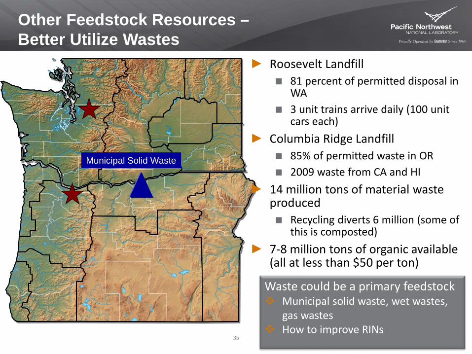
Other Feedstock Resources –Better Utilize Wastes
Municipal Solid Waste
Roosevelt Landfill81 percent of permitted disposal in WA3 unit trains arrive daily (100 unit cars each)
Columbia Ridge Landfill85% of permitted waste in OR2009 waste from CA and HI
14 million tons of material waste produced
Recycling diverts 6 million (some of this is composted)
7-8 million tons of organic available (all at less than $50 per ton)
Waste could be a primary feedstock Municipal solid waste, wet wastes,
gas wastes How to improve RINs
35