Embed Size (px)
Citation preview
LIQUID BATH MODEL ORION 796
ISSUE 3 –03/09
Page 1 of 25
LIQUID BATH MODEL
ORION 796
User Maintenance Manual/Handbook
Isothermal Technology Limited, Pine Grove, Southport, PR9 9AG, England
Tel: +44 (0)1704 543830 Fax: +44 (0)1704 544799 Internet: www.isotech.co.uk E-mail: [email protected]
The company is always willing to give technical advice and assistance where appropriate. Equally, because of the programme of continual
development and improvement we reserve the right to amend or alter characteristics and design without prior notice. This publication is
for information only.
LIQUID BATH MODEL ORION 796
ISSUE 3 –03/09
Page 2 of 25
CONTENTS
EMC INFORMATION ................................................................................................................................................. 4
ELECTRICAL SAFETY ................................................................................................................................................ 4
HEALTH AND SAFETY INSTRUCTIONS.............................................................................................................. 5
GUARANTEE........................................................................................................................................................................ 6
CAUTIONARY NOTE ............................................................................................................................................... 7
SPECIFICATION.................................................................................................................................................................. 8
ON ARRIVAL .............................................................................................................................................................. 9
IMPORTANT READ THIS NOW!.......................................................................................................................... 10
CHILLERS ......................................................................................................................................................................... 10 Chiller function ............................................................................................................................................................... 10
SETTING UP..................................................................................................................................................................... 11
FRONT PANEL CONTROLS ........................................................................................................................................... 12
REAR PANEL ...................................................................................................................................................................... 13
USING THE CONTROLLER ............................................................................................................................................ 14
FRONT PANEL LAYOUT................................................................................................................................................. 14 The Temperature Controller............................................................................................................................................ 14 Altering the Setpoint ....................................................................................................................................................... 14
ADVANCED CONTROLLER FEATURES.................................................................................................................................... 14 Setpoint Ramp Rate ........................................................................................................................................................ 14 Instrument Address ......................................................................................................................................................... 15
MONITORING THE CONTROLLER STATUS ............................................................................................................................. 15 Units .............................................................................................................................................................................. 15
OVER TEMPERATURE CONTROLLER (H MODEL ONLY) ......................................................................................................... 16 OVER AND UNDER TEMPERATURE CONTROLLER (M MODEL ONLY) ..................................................................................... 16 OVER TEMPERATURE CONDITION........................................................................................................................................ 16
OPERATION AND INITIAL TESTING .......................................................................................................................... 18
CHOICE OF LIQUIDS ....................................................................................................................................................... 19
LIQUID LEVEL...................................................................................................................................................................... 19
CHANGING LIQUIDS ...................................................................................................................................................... 20
USING THE COOLING COIL .......................................................................................................................................... 21
USING THE PC INTERFACE ........................................................................................................................................... 22
CONNECTIONS ................................................................................................................................................................... 22 USING THE INTERFACE ........................................................................................................................................................ 22

LIQUID BATH MODEL ORION 796
ISSUE 3 –03/09
Page 3 of 25
CAL NOTEPAD.................................................................................................................................................................. 23
MINIMUM SYSTEM REQUIREMENTS ....................................................................................................................................... 23 Development .................................................................................................................................................................. 23 License ........................................................................................................................................................................... 23
INSTALLING CAL NOTEPAD ................................................................................................................................................. 24 STARTING CAL NOTEPAD.................................................................................................................................................... 24 PROTOCOL ......................................................................................................................................................................... 24
ACCESSORIES ................................................................................................................................................................... 25

LIQUID BATH MODEL ORION 796
ISSUE 3 –03/09
Page 4 of 25
EMC INFORMATION
This product meets the requirements of the European Directive on Electromagnetic Compatibility (EMC)
89/336/EEC as amended by EC Directive 92/31/EEC and the European Low Voltage Directive 73/25/EEC,
amended by 93/68/EEC. To ensure emission compliance please ensure that any serial communications
connecting leads are fully screened.
The product meets the susceptibility requirements of EN 50082-1, criterion B.
Symbol Identification Publication Description
ISO3864 Caution (refer to handbook)
IEC 417 Caution, Hot Surface
ELECTRICAL SAFETY
This equipment must be correctly earthed.
This equipment is a Class 1 Appliance. A protective earth is used to ensure the conductive parts can not become
live in the event of a failure of the insulation.
The protective conductor of the flexible mains cable which is coloured green/yellow MUST be connected to a
suitable earth.
The blue conductor should be connected to Neutral and the Brown conductor to Live (Line).
Warning: Internal mains voltage hazard. Do not remove the panels.
LIQUID BATH MODEL ORION 796
ISSUE 3 –03/09
Page 5 of 25
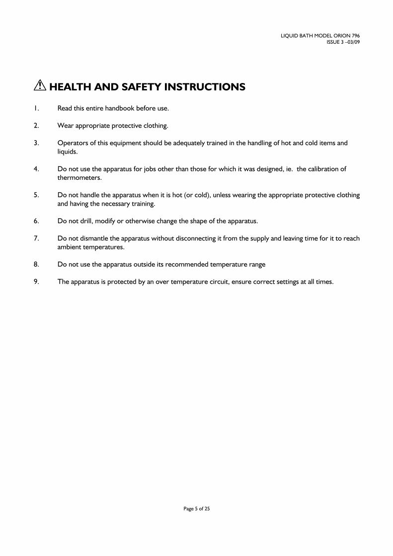
HEALTH AND SAFETY INSTRUCTIONS
1. Read this entire handbook before use.
2. Wear appropriate protective clothing.
3. Operators of this equipment should be adequately trained in the handling of hot and cold items and
liquids.
4. Do not use the apparatus for jobs other than those for which it was designed, ie. the calibration of
thermometers.
5. Do not handle the apparatus when it is hot (or cold), unless wearing the appropriate protective clothing
and having the necessary training.
6. Do not drill, modify or otherwise change the shape of the apparatus.
7. Do not dismantle the apparatus without disconnecting it from the supply and leaving time for it to reach
ambient temperatures.
8. Do not use the apparatus outside its recommended temperature range
9. The apparatus is protected by an over temperature circuit, ensure correct settings at all times.
LIQUID BATH MODEL ORION 796
ISSUE 3 –03/09
Page 6 of 25
GUARANTEE
This instrument has been manufactured to exacting standards and is guaranteed for twelve months against
electrical break-down or mechanical failure caused through defective material or workmanship, provided the
failure is not the result of misuse. In the event of failure covered by this guarantee, the instrument must be
returned, carriage paid, to the supplier for examination and will be replaced or repaired at our option.
FRAGILE CERAMIC AND/OR GLASS PARTS ARE NOT COVERED BY THIS GUARANTEE
INTERFERENCE WITH OR FAILURE TO PROPERLY MAINTAIN THIS INSTRUMENT MAY INVALIDATE
THIS GUARANTEE
RECOMMENDATION
The life of your ISOTECH Instrument will be prolonged if regular maintenance and cleaning to remove general
dust and debris is carried out.
ISOTHERMAL TECHNOLOGY LTD.
PINE GROVE, SOUTHPORT
PR9 9AG, ENGLAND
TEL: +44 (0) 1704 543830/544611
FAX: +44 (0)1704) 544799
The company is always willing to give technical advice and assistance where appropriate. Equally, because of the
programme of continual development and improvement we reserve the right to amend or alter characteristics
and design without prior notice. This publication is for information only.

LIQUID BATH MODEL ORION 796
ISSUE 3 –03/09
Page 7 of 25
CAUTIONARY NOTE
ISOTECH PRODUCTS ARE INTENDED FOR USE BY TECHNICALLY TRAINED AND COMPETENT
PERSONNEL FAMILIAR WITH GOOD MEASUREMENT PRACTICES.
IT IS EXPECTED THAT PERSONNEL USING THIS EQUIPMENT WILL BE COMPETENT WITH THE
MANAGEMENT OF APPARATUS WHICH MAY BE POWERED OR UNDER EXTREMES OF TEMPERATURE,
AND ARE ABLE TO APPRECIATE THE HAZARDS WHICH MAY BE ASSOCIATED WITH, AND THE
PRECAUTIONS TO BE TAKEN WITH, SUCH EQUIPMENT.
LIQUID BATH MODEL ORION 796
ISSUE 3 –03/09
Page 8 of 25
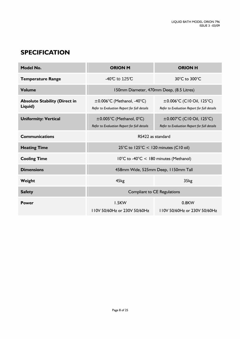
SPECIFICATION
Model No. ORION M ORION H
Temperature Range -40°C to 125°C 30°C to 300°C
Volume 150mm Diameter, 470mm Deep, (8.5 Litres)
Absolute Stability (Direct in
Liquid)
±0.006°C (Methanol, -40°C)
Refer to Evaluation Report for full details
±0.006°C (C10 Oil, 125°C)
Refer to Evaluation Report for full details
Uniformity: Vertical ±0.005°C (Methanol, 0°C)
Refer to Evaluation Report for full details
±0.007°C (C10 Oil, 125°C)
Refer to Evaluation Report for full details
Communications RS422 as standard
Heating Time 25°C to 125°C < 120 minutes (C10 oil)
Cooling Time 10°C to -40°C < 180 minutes (Methanol)
Dimensions 458mm Wide, 525mm Deep, 1150mm Tall
Weight 45kg 35kg
Safety Compliant to CE Regulations
Power 1.5KW
110V 50/60Hz or 230V 50/60Hz
0.8KW
110V 50/60Hz or 230V 50/60Hz
LIQUID BATH MODEL ORION 796
ISSUE 3 –03/09
Page 9 of 25
ON ARRIVAL
Check List.
You should have the following parts,
1. Main Bath Assembly
2. One overflow and one drain pipe
3. Lid
4. This handbook
5. PC Interface Lead (yellow) and Adapter
Optional accessories are available and will only be present if specified on your order.
In the unlikely event of any items arriving damaged please retain the packing materials (which may need to be
inspected later) and then contact your supplier.
LIQUID BATH MODEL ORION 796
ISSUE 3 –03/09
Page 10 of 25
IMPORTANT READ THIS NOW!
CHILLERS
The M and L models include an internal mechanical refrigeration unit. During transit the internal oil can be
displaced. On arrival the equipment should be left for 24 hours in an upright position to allow any displaced oil to
settle.
Chiller function
The chiller is designed to automatically enable at any temperature below 40°C. The chiller will run all the time
and the temperature control is balanced by the heater. The chiller will have unwanted cooling power at the
higher temperatures, such as temperatures above -10°C; it can cause unwanted instability in the liquid
temperature. To prevent this, the Orion has an automatic cooling reduction facility built in. This is in the form of
an internal by-pass valve that will reduce the running pressure of the refrigeration system.
The by-pass valve will automatically enable at temperatures above -10°C until the chiller is automatically
switched off at 40°C. Because of the time taken to cool down from higher temperatures with the by-pass
enabled and reduced cooling, the by-pass valve only actually opens when the actual temperature is within ±3 °C
of the set point. This allows the full cooling at all other times.
Further cooling power reduction is enabled via the cooling power adjustment fitted to the front panel. This is a
manual adjustment and may offer improved liquid stability at setpoint. Turning the adjustment fully clockwise will
fully close the valve allowing full cooling. This feature will operate at any temperature below 40°C.
The functions of the chiller can be identified by the display of the controller on the front panel. Refer to the
controller section on page 14 for details.
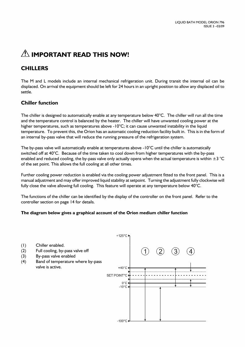
The diagram below gives a graphical account of the Orion medium chiller function
(1) Chiller enabled.
(2) Full cooling, by-pass valve off
(3) By-pass valve enabled
(4) Band of temperature where by-pass
valve is active.

LIQUID BATH MODEL ORION 796
ISSUE 3 –03/09
Page 11 of 25
SETTING UP
The whole manual should be carefully read before using the bath, and then set the bath up as follows.
Connect the drain pipe to the drain tap and the overflow pipe to the rear panel ports. Place a suitable container
under the overflow pipe. Ensure the tap is shut, i.e. lever at 90°. If the equalising block is to be used it should be
placed in position now.
Fill the bath with suitable liquid, water is probably best for initial testing. Fill the bath until the level is 45mm
below the top lid of the bath.
ALWAYS ISOLATE THE BATH FROM THE ELECTRICAL SUPPLY WHEN CHANGING LIQUIDS

LIQUID BATH MODEL ORION 796
ISSUE 3 –03/09
Page 12 of 25
FRONT PANEL CONTROLS
Cooling Power and Cool Enable are only present on the Hydra M model.
The cooling power control permits the power to be reduced from maximum and fine tuning of performance at
different temperatures.
Full clockwise is maximum cooling.
Set the flow control to suit the liquid and operating temperature.

LIQUID BATH MODEL ORION 796
ISSUE 3 –03/09
Page 13 of 25
REAR PANEL
LIQUID BATH MODEL ORION 796
ISSUE 3 –03/09
Page 14 of 25
USING THE CONTROLLER
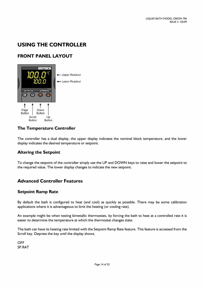
FRONT PANEL LAYOUT
The Temperature Controller
The controller has a dual display, the upper display indicates the nominal block temperature, and the lower
display indicates the desired temperature or setpoint.
Altering the Setpoint
To change the setpoint of the controller simply use the UP and DOWN keys to raise and lower the setpoint to
the required value. The lower display changes to indicate the new setpoint.
Advanced Controller Features
Setpoint Ramp Rate
By default the bath is configured to heat (and cool) as quickly as possible. There may be some calibration
applications where it is advantageous to limit the heating (or cooling rate).
An example might be when testing bimetallic thermostats, by forcing the bath to heat at a controlled rate it is
easier to determine the temperature at which the thermostat changes state.
The bath can have its heating rate limited with the Setpoint Ramp Rate feature. This feature is accessed from the
Scroll key. Depress the key until the display shows,
OFF
SP.RAT
LIQUID BATH MODEL ORION 796
ISSUE 3 –03/09
Page 15 of 25
The upper display will show the current value and is adjustable from OFF to 999.9. The units are °C/min and are
adjustable via the UP/DOWN keys.
When the SP.RAT is active the lower setpoint display will now automatically update with the current value,
known as the working setpoint. The setpoint can be seen by pressing either the UP and DOWN key.
The Setpoint ramp rate operates when the bath is heating and cooling.
Instrument Address
The controller has a configurable "address" which is used for PC communications. Each instrument has an
address; this allows several instruments to be connected in parallel on the same communications bus. The default
value is 1. This address would only need to be changed if more than one Dry Block is connected to the same PC
port.
To check the Address value press the scroll key until the lower display indicates,
ADDR
The upper display will show the current value that can be modified with the UP and DOWN keys.
Monitoring the Controller Status
A row of beacons indicate the controllers status as follows,
Output 1 (op1) Heater – shows when the heater is active, seen to pulse to display heater output
REM
This beacon indicates activity on the PC interface
Output 2 (op2) Full cooling – When illuminated shows full cooling and the by-pass valve is closed. When
not illuminated, indicates the by-pass valve is open and reduced cooling is enabled
Output 4 (op4) Indicates the chiller is enabled and working
Units
The units can be changed from °C. Press the scroll key until the lower displays shows
UNITS
Use the UP and DOWN keys to select the desired display unit.
LIQUID BATH MODEL ORION 796
ISSUE 3 –03/09
Page 16 of 25
Over Temperature Controller (H Model Only)
This device is an important safety feature. It has its own temperature sensor and will isolate the heater if the
temperature exceeds the set temperature. It should be set slightly higher, perhaps 10 – 20°C higher than the
working temperature or to the maximum safe temperature of the fluid in use. Which ever is the lowest value. IT
MUST BE SET IN THIS WAY TO ENSURE SAFE USE OF THE BATH. Suitably set it will allow for protection
against component failure and also operator error when setting the controller, either from the front panel or
remotely from a computer.
The heat enabled beacon will be lit when the over-temperature controller is in safe mode.
Set the desired value on the lower display using the UP and DOWN keys.
Over and Under Temperature Controller (M Model Only)
The M model has a low temperature trip in addition to a high temperature trip. The low temperature trip will
turn the chiller off and can be used to safe guard water triple point cells or the liquid in the bath from freezing.
The high trip will isolate the heater if the bath temperature exceeds the set value.
Set the High Trip value to a suitable value, perhaps 10 – 20°C higher than the operating temperature but lower
than the flash point of the liquid. Set this value into the A1 Hi Parameter.
Set the Low Trip value to a suitable value, perhaps the minimum safe operating temperature for the calibration
into the A2 Lo Parameter.
To access these parameters press the scroll key until they appear on the lower display and modify the value
shown on the top display with the up and down keys.
Over Temperature Condition
In the unlikely event of an over temperature or under temperature condition the Orion will go to Alarm
condition. Depending which of the alarms has been triggered the unit will either disable the heater or the cooler
accordingly.
The Temperature Policeman controller will identify which alarm has been triggered by the scrolling lower
display. The message will read as follows:
OVERTEMPERATURE CONDITION – ATTENTION REQUIRED
UNDERTEMPERATURE CONDITION – ATTENTION REQUIRED
The respective illuminated beacon will also switch off.

LIQUID BATH MODEL ORION 796
ISSUE 3 –03/09
Page 17 of 25
To reset the heater or cooler, the condition must be removed, that is the temperature must be restored to the
correct value by either waiting for the temperature to normalise, or by resetting the controller to a more suitable
value.
The controller will need to be reset manually, even if the controller is switched off, it will still power up again in
the alarm condition until reset.
To reset the controller, ensure the temperature for both over and under temperature is safe then press both the
PAGE button and the SCROLL button simultaneously. The scrolling warning display will disappear and the
illuminated beacon light up.
LIQUID BATH MODEL ORION 796
ISSUE 3 –03/09
Page 18 of 25
OPERATION AND INITIAL TESTING
Set the bath up as described in the earlier "Setting Up Section". For convenience it is suggested that a newly
received bath should be tested at 50EC with water as the operating liquid.
Connect the bath to the supply and switch on.
1. Set the over temperature controller to a suitable value, see earlier.
2. Set the set point of the temperature controller to the desired value (50.0EC).
3. Ensure correct operation of the bath.
LIQUID BATH MODEL ORION 796
ISSUE 3 –03/09
Page 19 of 25
CHOICE OF LIQUIDS
The choice of liquid is important. If it is too viscous at the operating temperature then the bath may not perform
correctly. Other criteria also need to be met, such as safety, operating range and fume emission for example.
Isotech is able to supply a number of fluids for various temperature ranges, refer to Databook 2.
Unfortunately, there is not one fluid which can be used over the whole operating range of the bath.
Beware of oils that are claimed to work from below ambient to over 100°C. Whilst we do not supply or
recommend such liquids, others do. It is our experience that such oils absorb moisture from the air when used
below the dew point. Then at temperatures around 100°C this moisture boils and can lead to the oil spilling from
the top of the bath. Even without the boiling risk, the oil is soon spoilt by the ingressions of moisture and the oil
has to be replaced regularly, which can be an expensive task. It will be seen that when changing fluids from say
water to oil that it is important that ALL the water has been removed before adding the oil.
As oils approach their upper operating limit fumes become significant and fume extraction becomes essential.
Isothermal Technology manufactures a Fluidised Alumina Bath, the Ayries Bath which overcomes the limitations
of oils and may be used to 700EC without fuming problems.
Below ambient we use a mixture of methanol and water. Methanol is poisonous and has a low flash point. It
needs to be used very carefully by those suitably trained and aware of the dangers if handled inappropriately. As
local safety requirements vary not only from country to country but also from organisation to organisation the
safety aspects of these fluids should be determined with the user’s safety officer.
Liquid Level
All liquids expand as they are heated and contract when they cool.
The bath has been designed to allow for varying liquid volumes and also features an overflow system which
prevents the liquid from spilling from the top of the bath.
The overflow will be seen on the top right of calibration tube. Ensure at the operating temperature the level is
within 10-70mm of the overflow opening.
Ensure at all time that the liquid level is kept at the correct level and that the liquid is circulating around the bath.
If the level falls excessively the flow will stop with a consequence of large temperature gradients. If a liquid is
being used close to its flash point a hazard could then occur.
LIQUID BATH MODEL ORION 796
ISSUE 3 –03/09
Page 20 of 25
CHANGING LIQUIDS
If possible it is best to plan so that liquids do not need to be frequently changed. This may be achieved by liquid
choice, determining convenient calibration points or having more than one bath - each with a different liquid to
cover the routine calibration range.
To change the liquid,
1. Disconnect from the supply.
2. Ensure the liquid is at a safe handling temperature. Neither too hot nor too cool then open the drain tap.
3. Drain the liquid into clean containers of adequate capacity, properly labelled for future use.
4. Clean the bath. Detergent and absorbent paper will assist. If the bath has been used with an oil, it can be
helpful to re fill with water and detergent and to allow the mixture to circulate before draining again.
5. Close the tap.

LIQUID BATH MODEL ORION 796
ISSUE 3 –03/09
Page 21 of 25
USING THE COOLING COIL
The Orion has an internal cooling coil fitted. Access for the cooling coil is via two bulkhead fittings on the rear
panel.
Water passed through the coil will substantially reduce the cooling time. To avoid any hazard from the expansion
of water to steam do not use water at temperatures in excess of 100°C and ensure water is drained from the coil
before setting the Hydra above 100°C.
LIQUID BATH MODEL ORION 796
ISSUE 3 –03/09
Page 22 of 25
USING THE PC INTERFACE
The bath includes an RS422 PC interface and a special converter cable that allows use with the standard RS232
port. When using the bath with an RS232 port it is essential that this converter cable is used. Replacement cables
are available from Isotech, part number ISO-232-432. A further lead is available as an option, Part Number
ISO-422-422 lead which permits up to 5 instruments to be daisy chained together.
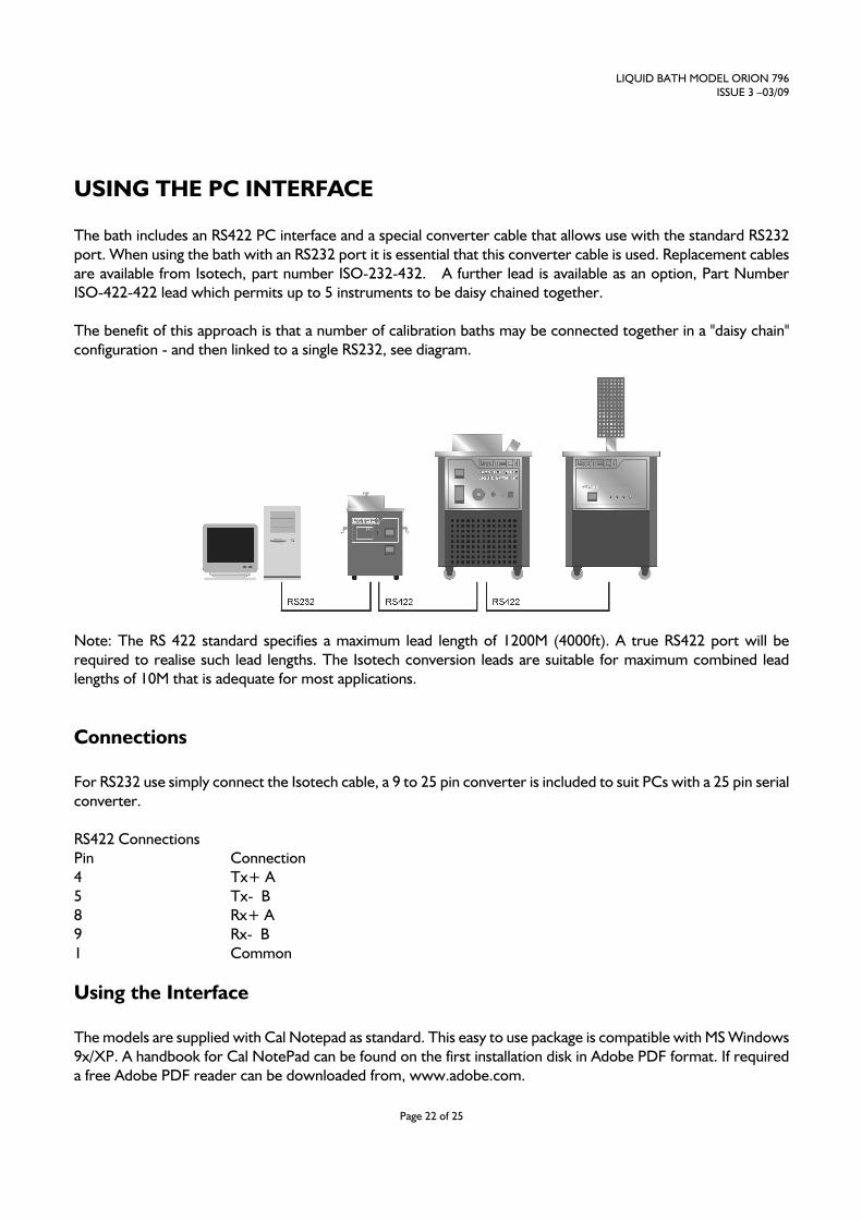
The benefit of this approach is that a number of calibration baths may be connected together in a "daisy chain"
configuration - and then linked to a single RS232, see diagram.
Note: The RS 422 standard specifies a maximum lead length of 1200M (4000ft). A true RS422 port will be
required to realise such lead lengths. The Isotech conversion leads are suitable for maximum combined lead
lengths of 10M that is adequate for most applications.
Connections
For RS232 use simply connect the Isotech cable, a 9 to 25 pin converter is included to suit PCs with a 25 pin serial
converter.
RS422 Connections
Pin Connection
4 Tx+ A
5 Tx- B
8 Rx+ A
9 Rx- B
1 Common
Using the Interface
The models are supplied with Cal Notepad as standard. This easy to use package is compatible with MS Windows
9x/XP. A handbook for Cal NotePad can be found on the first installation disk in Adobe PDF format. If required
a free Adobe PDF reader can be downloaded from, www.adobe.com.

LIQUID BATH MODEL ORION 796
ISSUE 3 –03/09
Page 23 of 25
CAL NOTEPAD
Cal Notepad can be used to log and display values from the bath and an optional temperature indicator.
Minimum System Requirements
CNP requires Windows 95 / 98, a minimum of 5Mb of free hard drive space and free serial ports for the
instruments to be connected.
Development
CNP was developed by Isothermal Technology using LabVIEW from National Instruments.
License
Use of the Cal NotePad software program "CNP" is as granted in this license agreement. In using the CNP
software the user "licensee" is agreeing to the terms of the license. You must read and understand the terms of this license
before using CNP.
1, This license permits licensee to use CNP software on a single computer. The user may make copies for back up and
archival purposes freely as long as the software is only ever in use on a single computer at any one time. Please enquire about
multi-user licenses.
2, CNP is protected by international copyright laws and treaties. CNP must not be distributed to third parties.
3, CNP must not be reversed engineered, disassembled or de-compiled. Licensee may transfer the software to a third party
provided that no copies or upgrades of CNP are retained.
4, It is the responsibility of the user to ensure the validity of all stored results and printed certificates. Isothermal
Technology Ltd accept no responsibility for any errors caused by inappropriate use, incorrect set up or any other cause;
including defects in the software.
5, Limited Warranty. Isothermal Technology warrants that CNP will perform substantially as described in this manual for a
period of 90 days from receipt. Any distribution media will under normal used be guaranteed for a period of 90 days.
NO OTHER WARRANTIES, EXCEPT AS STATED ABOVE. The software and documentation is provided "as is" without
warranty of any kind and no other warranties (either expressed or implied) are made with regard to CNP. Isothermal
Technology does not warrant, guarantee or make any representations regarding the use or results of the use of the software
or documentation and does not warrant that the operation of CNP will be error free.
In no event will Isothermal Technology, its employees, agents or other associated people be liable for direct, indirect,
incidental or consequential damages, expenses, lost profits, business interruption, lost business information or other
damages arising out the use or inability to use CNP. The license fee reflects this allocation of risk.
CNP is not designed for situations where the results can threaten or cause injury to humans.
LIQUID BATH MODEL ORION 796
ISSUE 3 –03/09
Page 24 of 25
Installing Cal NotePad
1. Insert CNP DISK 1 into the disk drive
2 Click on the START button on the task bar, select RUN, type A:\SETUP (Where A: is your drive letter)
then click OK
3 Follow the prompts which will install the application and necessary LabVIEW run time support files.
4 Should you ever need to uninstall the software then use the Add/Remove Programs option from the
Control Panel.
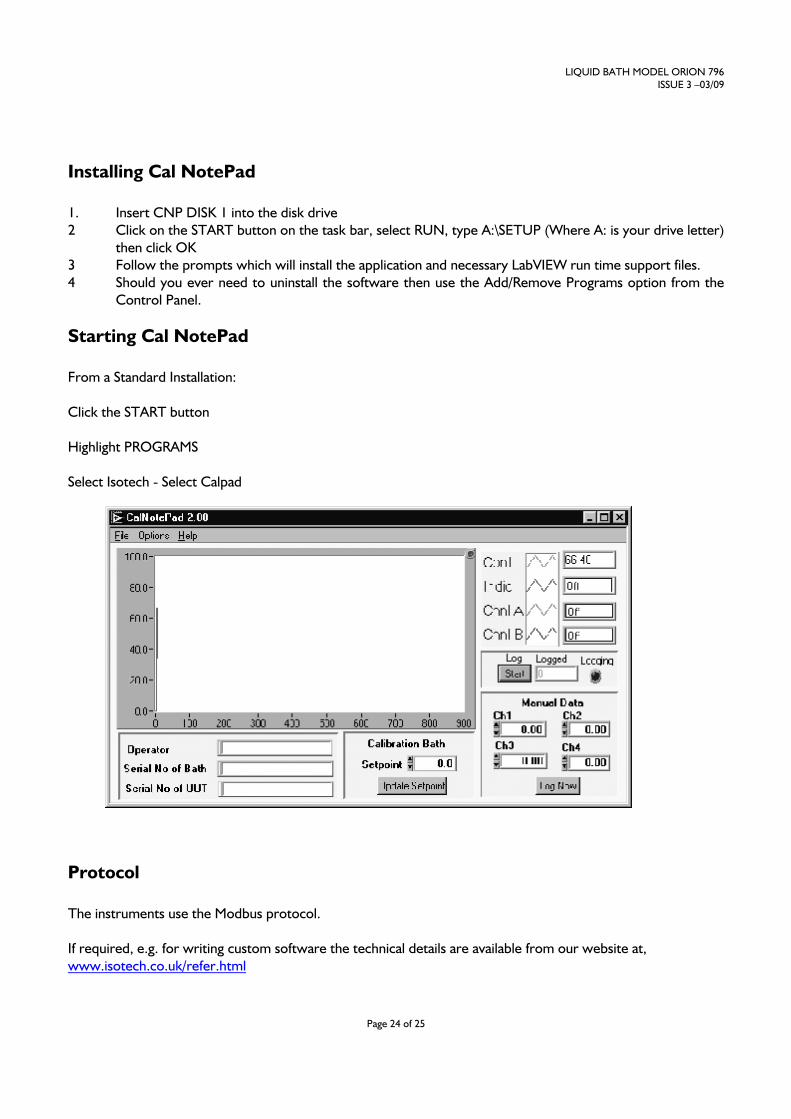
Starting Cal NotePad
From a Standard Installation:
Click the START button
Highlight PROGRAMS
Select Isotech - Select Calpad
Protocol
The instruments use the Modbus protocol.
If required, e.g. for writing custom software the technical details are available from our website at,
www.isotech.co.uk/refer.html
LIQUID BATH MODEL ORION 796
ISSUE 3 –03/09
Page 25 of 25
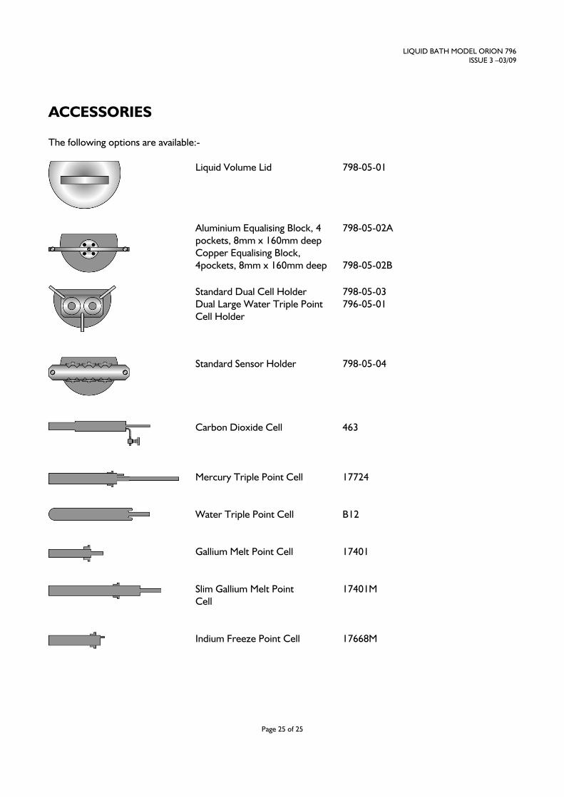
ACCESSORIES
The following options are available:-
Liquid Volume Lid 798-05-01
Aluminium Equalising Block, 4
pockets, 8mm x 160mm deep
Copper Equalising Block,
4pockets, 8mm x 160mm deep
798-05-02A
798-05-02B
Standard Dual Cell Holder
Dual Large Water Triple Point
Cell Holder
798-05-03
796-05-01
Standard Sensor Holder
798-05-04
Carbon Dioxide Cell
463
Mercury Triple Point Cell
17724
Water Triple Point Cell
B12
Gallium Melt Point Cell
17401
Slim Gallium Melt Point
Cell
17401M
Indium Freeze Point Cell
17668M