Embed Size (px)
Citation preview

LETTERSPUBLISHED ONLINE: 12 OCTOBER 2014 | DOI: 10.1038/NMAT4105
Liquid-like pseudoelasticity of sub-10-nmcrystalline silver particlesJun Sun1†, Longbing He1†, Yu-Chieh Lo2,3,4†, Tao Xu1, Hengchang Bi1, Litao Sun1*, Ze Zhang5*,Scott X. Mao6 and Ju Li2,3*In nanotechnology, small-volume metals with large surfaceareaareusedaselectrodes, catalysts, interconnectsandanten-nae1–4. Their shape stability at room temperature has, however,been questioned. Using in situ high-resolution transmissionelectron microscopy, we find that Ag nanoparticles can bedeformed like a liquid droplet but remain highly crystallinein the interior, with no sign of dislocation activity duringdeformation5,6. Surface-di�usion-mediated pseudoelastic de-formation is evident at room temperature, which can be drivenby either an external force or capillary-energy minimization.Atomistic simulations confirm that such highly unusual Coblepseudoelasticity can indeed happen for sub-10-nm Ag par-ticles at room temperature and at timescales from secondsto months.
Nanotechnology requires precise shape control of components.Once a certain shape is made, it is often hoped that it staysunchanged over a long period of time. Nanoelectronicdevices with 14 nm feature sizes are commercially availableat present, and we may soon enter the sub-10-nm regime. Itis therefore essential to examine the shape change and shapestability of sub-10-nm material components, especially close toroom temperature.
Although both plastic and pseudoelastic deformations areused for shaping, and both incur energy dissipation, the essentialdifference is that, when unloaded to zero stress, a pseudoelasticcomponent always recovers to a single ‘rest shape’ regardless ofprevious deformation history, whereas a component deformed byplasticity has no memory of a single rest shape and will stay in thedeformed shape(s) at zero stress (see Supplementary Part 15 for anillustration of this difference). In this paperwewill showusing in situhigh-resolution transmission electron microscopy that sub-10-nmsingle crystals ofAgdeformpseudoelastically, rather thanplastically,at room temperature. This victory of pseudoelasticity over plasticityat the small extremes of size-dependent mechanical behaviour ofmetals5–9 can have three profound practical consequences: thereis no longer ‘plastic freedom’ at the small extremes—that is, theavailability of a large number of arbitrary, stress-free shapes; onecan still gain access to an infinite number of shapes, but differentfinite loads must be imposed via external constraints, similar toinflating a rubbery balloon; omni-directional, reconfigurableand damage-tolerant contact is suddenly possible at thisextreme scale.
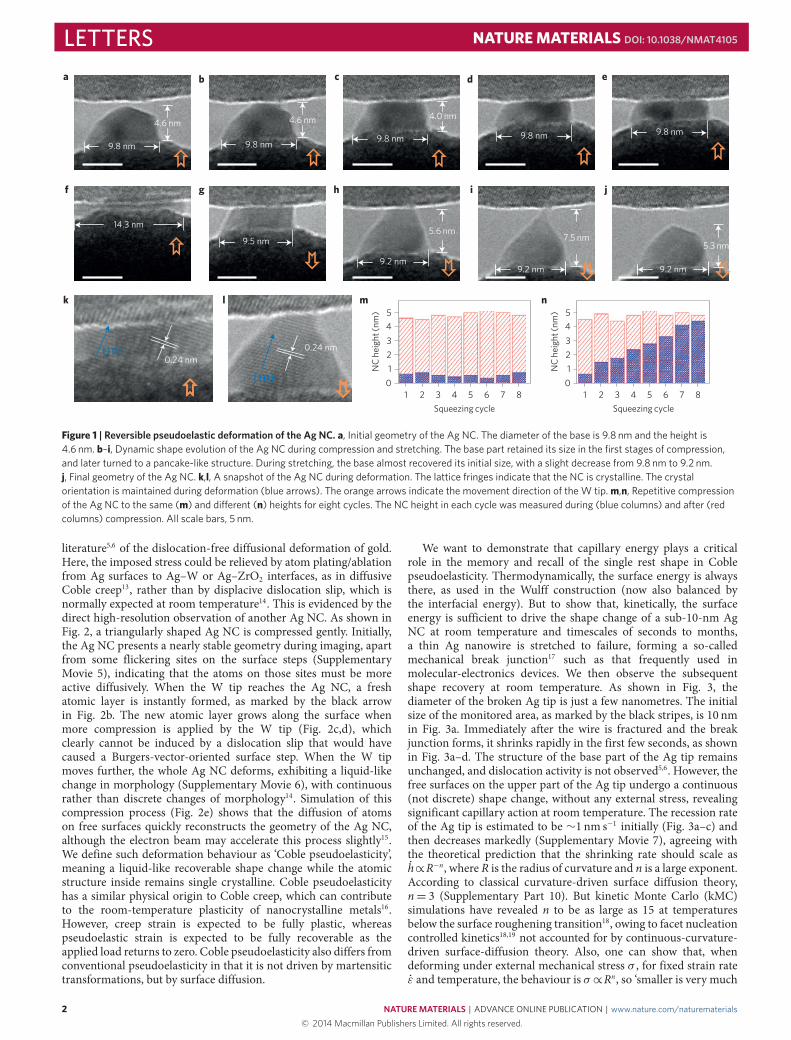
Liquid-like deformation of silver nanocrystalsFigure 1 shows a typical cycle of compression and stretching of asilver (Ag) nanocrystal (NC) with a base diameter of 9.8 nm andpartially bonded on the surface of a W tip. The NC height is 4.6 nmand the shape is stable under electron-beam irradiation duringnormal imaging (the beam intensity of 3.8 A cm−2 is much weakerthan in normal practice)10,11 (Methods and Supplementary Part 1).This shape probably possesses the minimum free energy. The facetshown in Fig. 1a corresponds to the (111) crystal plane of Ag(Supplementary Part 2). As the NC-decoratedW tip approaches thecrystalline ZrO2 above (Fig. 1b), the top of the Ag NC snaps slightlyonto the ZrO2 surface, as a result of van der Waals attraction12.The upper part of the Ag NC is then deformed, as can be seenin Fig. 1c. As the W tip further approaches the ZrO2, compressivestress is spread onto the entire Ag NC. In Fig. 1d–f, the AgNC undergoes drastic deformation, resulting eventually in a flatpancake-like shape. During the process, the outer morphology ofthe Ag NC changes similarly to a liquid drop (SupplementaryMovies 1–3). However, high-resolution images taken during theprocess prove that the deforming Ag nanoparticle remains singlecrystalline (Fig. 1k,l) inside. When the W tip is detached fromthe ZrO2 (Fig. 1f–i), the Ag NC surprisingly starts to recover itsoriginal shape and the base diameter decreases from 14.3 to 9.5 nmin the first stage, and then to 9.2 nm. The height of the Ag NCrecovered quickly and a thin sharp Ag tip meniscus (Fig. 1i) isformed. When the tip is finally detached, the shape of the AgNC changes rapidly from an elongated spire to a stable geometrywith facets similar to its initial ones (Fig. 1j). Such a reversiblechange in shape (except for missing atoms induced by effects suchas tip scratching and electron bombardment, which break the idealbehaviour) is infinitely repeatable (Fig. 1m,n and SupplementaryMovies 1 and 2) just like the deformation of a water droplet, also forlateral squeezing (Supplementary Part 16) and for smaller Ag NCs(Supplementary Movie 4). Thus, the videotaped deformations arepseudoelastic rather than plastic; the memory of a single rest shapecan be explained by capillary-energyminimization—that is, the restshape is the result of the balance between Ag surface energy andAg–W interfacial energy.
Surface-di�usion-dominated Coble pseudoelasticityNext we demonstrate that the atomic mechanism behind theshape evolution is surface diffusion. There is prior evidence in the
1SEU-FEI Nano-Pico Center, Key Lab of MEMS of Ministry of Education, Southeast University, Nanjing, 210096, China, 2Department of Nuclear Scienceand Engineering, Massachusetts Institute of Technology, Cambridge, Massachusetts 02139, USA, 3Department of Materials Science and Engineering,Massachusetts Institute of Technology, Cambridge, Massachusetts 02139, USA, 4Center for Elements Strategy Initiative for Structural Materials (ESISM),Kyoto University, Sakyo, Kyoto 606-8501, Japan, 5Department of Materials Science and Engineering, State Key Laboratory of Silicon Materials, ZhejiangUniversity, Hangzhou 310027, China, 6Department of Mechanical Engineering and Materials Science, University of Pittsburgh, 3700 O’Hara Street,Pittsburgh, Pennsylvania 15261, USA. †These authors contributed equally to this work. *e-mail: [email protected]; [email protected]; [email protected]
NATURE MATERIALS | ADVANCE ONLINE PUBLICATION | www.nature.com/naturematerials 1© 2014 Macmillan Publishers Limited. All rights reserved.
LETTERS NATUREMATERIALS DOI: 10.1038/NMAT4105
a b d ec
9.8 nm
14.3 nm
9.8 nm
9.5 nm
9.2 nm9.2 nm 9.2 nm
9.8 nm 9.8 nm 9.8 nm4.6 nm 4.6 nm 4.0 nm
5.6 nm7.5 nm
5.3 nm
gf h i j
k5
ml n
NC
heig
ht (n
m)
1234
0.24 nm0.24 nm[111]
[111] 0
Squeezing cycle1 2 3 4 5 6 7 8
5
NC
heig
ht (n
m)
1234
0
Squeezing cycle1 2 3 4 5 6 7 8
Figure 1 | Reversible pseudoelastic deformation of the Ag NC. a, Initial geometry of the Ag NC. The diameter of the base is 9.8 nm and the height is4.6 nm. b–i, Dynamic shape evolution of the Ag NC during compression and stretching. The base part retained its size in the first stages of compression,and later turned to a pancake-like structure. During stretching, the base almost recovered its initial size, with a slight decrease from 9.8 nm to 9.2 nm.j, Final geometry of the Ag NC. k,l, A snapshot of the Ag NC during deformation. The lattice fringes indicate that the NC is crystalline. The crystalorientation is maintained during deformation (blue arrows). The orange arrows indicate the movement direction of the W tip. m,n, Repetitive compressionof the Ag NC to the same (m) and di�erent (n) heights for eight cycles. The NC height in each cycle was measured during (blue columns) and after (redcolumns) compression. All scale bars, 5 nm.
literature5,6 of the dislocation-free diffusional deformation of gold.Here, the imposed stress could be relieved by atom plating/ablationfrom Ag surfaces to Ag–W or Ag–ZrO2 interfaces, as in diffusiveCoble creep13, rather than by displacive dislocation slip, which isnormally expected at room temperature14. This is evidenced by thedirect high-resolution observation of another Ag NC. As shown inFig. 2, a triangularly shaped Ag NC is compressed gently. Initially,the Ag NC presents a nearly stable geometry during imaging, apartfrom some flickering sites on the surface steps (SupplementaryMovie 5), indicating that the atoms on those sites must be moreactive diffusively. When the W tip reaches the Ag NC, a freshatomic layer is instantly formed, as marked by the black arrowin Fig. 2b. The new atomic layer grows along the surface whenmore compression is applied by the W tip (Fig. 2c,d), whichclearly cannot be induced by a dislocation slip that would havecaused a Burgers-vector-oriented surface step. When the W tipmoves further, the whole Ag NC deforms, exhibiting a liquid-likechange in morphology (Supplementary Movie 6), with continuousrather than discrete changes of morphology14. Simulation of thiscompression process (Fig. 2e) shows that the diffusion of atomson free surfaces quickly reconstructs the geometry of the Ag NC,although the electron beam may accelerate this process slightly15.We define such deformation behaviour as ‘Coble pseudoelasticity’,meaning a liquid-like recoverable shape change while the atomicstructure inside remains single crystalline. Coble pseudoelasticityhas a similar physical origin to Coble creep, which can contributeto the room-temperature plasticity of nanocrystalline metals16.However, creep strain is expected to be fully plastic, whereaspseudoelastic strain is expected to be fully recoverable as theapplied load returns to zero. Coble pseudoelasticity also differs fromconventional pseudoelasticity in that it is not driven by martensitictransformations, but by surface diffusion.
We want to demonstrate that capillary energy plays a criticalrole in the memory and recall of the single rest shape in Coblepseudoelasticity. Thermodynamically, the surface energy is alwaysthere, as used in the Wulff construction (now also balanced bythe interfacial energy). But to show that, kinetically, the surfaceenergy is sufficient to drive the shape change of a sub-10-nm AgNC at room temperature and timescales of seconds to months,a thin Ag nanowire is stretched to failure, forming a so-calledmechanical break junction17 such as that frequently used inmolecular-electronics devices. We then observe the subsequentshape recovery at room temperature. As shown in Fig. 3, thediameter of the broken Ag tip is just a few nanometres. The initialsize of the monitored area, as marked by the black stripes, is 10 nmin Fig. 3a. Immediately after the wire is fractured and the breakjunction forms, it shrinks rapidly in the first few seconds, as shownin Fig. 3a–d. The structure of the base part of the Ag tip remainsunchanged, and dislocation activity is not observed5,6. However, thefree surfaces on the upper part of the Ag tip undergo a continuous(not discrete) shape change, without any external stress, revealingsignificant capillary action at room temperature. The recession rateof the Ag tip is estimated to be ∼1 nm s−1 initially (Fig. 3a–c) andthen decreases markedly (Supplementary Movie 7), agreeing withthe theoretical prediction that the shrinking rate should scale ash∝R−n, where R is the radius of curvature and n is a large exponent.According to classical curvature-driven surface diffusion theory,n= 3 (Supplementary Part 10). But kinetic Monte Carlo (kMC)simulations have revealed n to be as large as 15 at temperaturesbelow the surface roughening transition18, owing to facet nucleationcontrolled kinetics18,19 not accounted for by continuous-curvature-driven surface-diffusion theory. Also, one can show that, whendeforming under external mechanical stress σ , for fixed strain rateε and temperature, the behaviour is σ ∝Rn, so ‘smaller is very much
2 NATURE MATERIALS | ADVANCE ONLINE PUBLICATION | www.nature.com/naturematerials© 2014 Macmillan Publishers Limited. All rights reserved.

NATUREMATERIALS DOI: 10.1038/NMAT4105 LETTERS
2.1 s 2.5 s 3.2 s 3.4 sa
b c d
Substrate Substrate Substrate
AgAg Ag
Tip TipTipNew surface Surface growth
e
Figure 2 | Atomic layer growth during compression. a, Flickering atoms on free surface of the Ag NC (black arrowheads). See also Supplementary Movie 5.b, Initial geometry of a nanometre-sized Ag NC. c,d, Growth of a fresh atomic layer after gently applying a compressive load. See also SupplementaryMovie 6. e, Simulated compression process of a Ag NC. The orange arrows indicate the movement direction of the tip. All scale bars, 5 nm.
weaker’ in the Coble deformation regime. The crossover from theHall–Petch-like ‘smaller is stronger’ trend σ ∝ R−α (α is usuallybetween 0.5 and 1) when displacive plasticity is active to the ‘smalleris very much weaker’ diffusive Coble deformation regime σ ∝Rn
should be sharp and sudden as R is reduced, owing to the largepositive exponent n. Put simply, we expect the strength to dropprecipitously with reducing size in the very small extremes.
Coble pseudoelasticity confirmed by atomistic calculationsInevitably, the imaging electron beam has some effects onthe sample20. Although we do not expect it to alter therest shape, electron-beam activation may accelerate surfacediffusion (Supplementary Part 14). To ascertain whether Coblepseudoelasticity requires an electron beam to be feasible atroom temperature, we perform atomistic calculations tosimulate the shape relaxation of a Ag NC break junction(Supplementary Movies 8–10). Because of the limited accessible
timescale of MD simulations, one strategy is to perform MD athigher temperatures, and then appropriately extrapolate to roomtemperature. The shape changes of MD simulations at 800Kfor tMD
800K = 0.1 µs are found to be similar in magnitude and form(Fig. 3e–g) to the TEM observations. Detailed analysis of theatomic trajectories in the 800K MD simulations (SupplementaryMovie 8) show that: the shape evolution was dominated by singleadatom movements, rather than chain or island processes; theshape change was indeed accomplished by atom ablation ofthe surface layers with greater curvature and by growth of thesurface layers with smaller curvature, while atoms two monolayersbelow the surface always remained highly crystalline; the shapechange is rate-controlled by atomic processes on non-(111)facets of the NC, as processes on (111) facets occurred muchfaster. These findings corroborate a database of activation-energy barriers (summarized in Supplementary Table 1) for FCCmetal surface diffusion21,22. The ranking of the activation energy
NATURE MATERIALS | ADVANCE ONLINE PUBLICATION | www.nature.com/naturematerials 3© 2014 Macmillan Publishers Limited. All rights reserved.

LETTERS NATUREMATERIALS DOI: 10.1038/NMAT4105
a b c d00:07 s 00:09 s 00:11 s 00:13 s
FracturedAg tip
e h00:30 s
f g
Height of shrinkage ∼2 nm10.8 nm
8.9 nm
10 n
m
7.7
nm
6.1 n
m
4.4
nm2.
0 nm
Figure 3 | Surface-energy-driven shape change. a, Initial geometry of the Ag tip after fracture. b–d, Shrinkage process of the Ag tip towards the base partafter fracture. e–g, MD simulations showing that the shrinkage process of the Ag nanoparticle tip is consistent with the experiments in a–c. h, When theradius of curvature of the particle increased, the shrinkage process became slower. All scale bars, 5 nm.
a b c d
Figure 4 | Simulated shape evolution of Ag NCs by surface di�usion. a, Island di�usion (red circle) was observed only on (111) surfaces. b,c, The potholedsurfaces were smoothed through a series of adatom migration and local reconstruction (yellow circles) on (001) facets. d, After a long time (0.1 µs), thesharp tip became blunter and the evolution slowed. 0.1 µs in the MD model at 800 K was long enough to mimic the shape change caused by Coble creep onthe Ag NC at room temperature. The colour gradient represents the di�erence in potential energy per atom; dark blue represents lower energy and lightblue represents higher energy.
barriers of single adatom hopping on different surface facets is:(110)out-channel>(001)> (110)in-channel>(111). Atom-chain diffusionwas also observed on (111) surfaces (Fig. 4a) and dispersed atthe edges with other planes: chain processes were not found onthe other facets21. The barriers against ascending adatoms arehigher than those against descending adatoms, and the barriers foradatoms leaving a corner are higher than for those approachinga corner22—thus, high-curvature regions tend to be flattened,a manifestation of the Gibbs–Thomson effect on the chemicalpotential, which drives the pseudoelasticity. When adatoms arrivedat uneven surfaces, they reordered the defective surface by aseries of hopping, exchange or pyramid-collapse atomic events, asshown in Supplementary Movie 8 and Fig. 4d. The ‘pothole-free’new surface then lowers the barriers for subsequent diffusingatoms23–26 (Fig. 4b,c).
MD simulations also showed that the Ag NC surface mostlyconsisted of (111) and (001) facets, as well as defective sitesnear corners or terraces. Many adatoms and small clusters werefound on the surface of those facets at the particle tip (Fig. 4).The crystallographic planes on the tip of 10 nm Ag nanoparticles
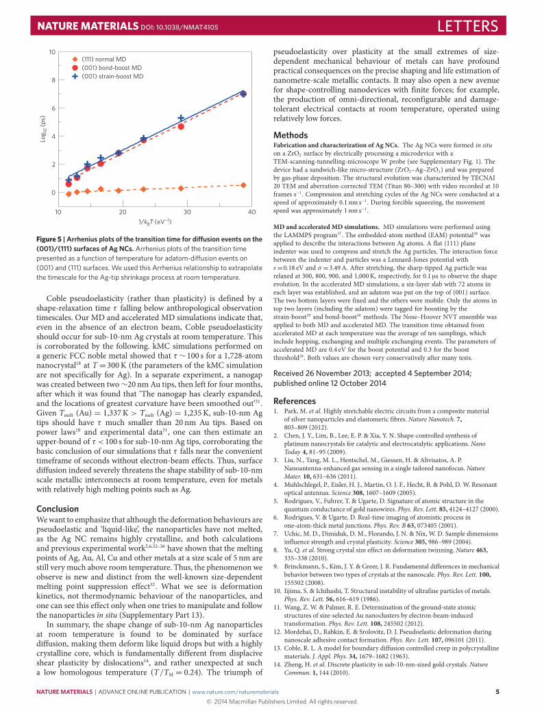
coincide with the Wulff construction for Ag/Au (refs 27,28). Wequantitatively estimated the timescale for room-temperature Coblepseudoelasticity, τ , by applying two newly developed acceleratedMD simulation schemes29,30 on (001) surface diffusion, whichshould be rate-controlling in the shape evolution. The distributionof average transition times at different temperatures shows astraight-line behaviour in the Arrhenius plot (Fig. 5). The timescaleof diffusion events between 300 and 800K shows only a smalldifference on (111), but varies by 5∼6 decades for adatom diffusionon the (001) surface, owing to the larger activation energy. Theenthalpy of a 10 nm Ag particle presents a linear relationshipbetween 300K and 800K (Supplementary Fig. 4), which suggestsno phase transformation in this temperature range. Therefore, mostdiffusion processes occurring at 800K may be extrapolated to300K directly in the Arrhenius fashion. According to the data inSupplemetary Table II, we extrapolated the timescale of the shapechange at 300K by tMD
800K (MD simulation time at 800K) ×105∼6(difference of timescale). Thus, we conclude that the shape evolutionor shape relaxation timescale at room temperature should beτ=0.01∼0.1 s for the simulated geometry.
4 NATURE MATERIALS | ADVANCE ONLINE PUBLICATION | www.nature.com/naturematerials© 2014 Macmillan Publishers Limited. All rights reserved.
NATUREMATERIALS DOI: 10.1038/NMAT4105 LETTERS
10 20 30 401/kBT (eV−1)
0
2
4
6
8
10Lo
g 10 (p
s)
(111) normal MD(001) bond-boost MD(001) strain-boost MD
Figure 5 | Arrhenius plots of the transition time for di�usion events on the(001)/(111) surfaces of Ag NCs. Arrhenius plots of the transition timepresented as a function of temperature for adatom-di�usion events on(001) and (111) surfaces. We used this Arrhenius relationship to extrapolatethe timescale for the Ag-tip shrinkage process at room temperature.
Coble pseudoelasticity (rather than plasticity) is defined by ashape-relaxation time τ falling below anthropological observationtimescales. Our MD and accelerated MD simulations indicate that,even in the absence of an electron beam, Coble pseudoelasticityshould occur for sub-10-nm Ag crystals at room temperature. Thisis corroborated by the following. kMC simulations performed ona generic FCC noble metal showed that τ ∼100 s for a 1,728-atomnanocrystal18 at T =300K (the parameters of the kMC simulationare not specifically for Ag). In a separate experiment, a nanogapwas created between two∼20 nmAu tips, then left for four months,after which it was found that ‘The nanogap has clearly expanded,and the locations of greatest curvature have been smoothed out’31.Given Tmelt (Au) = 1,337K > Tmelt (Ag) = 1,235K, sub-10-nm Agtips should have τ much smaller than 20 nm Au tips. Based onpower laws18 and experimental data31, one can then estimate anupper-bound of τ <100 s for sub-10-nm Ag tips, corroborating thebasic conclusion of our simulations that τ falls near the convenienttimeframe of seconds without electron-beam effects. Thus, surfacediffusion indeed severely threatens the shape stability of sub-10-nmscale metallic interconnects at room temperature, even for metalswith relatively high melting points such as Ag.
ConclusionWewant to emphasize that although the deformation behaviours arepseudoelastic and ‘liquid-like’, the nanoparticles have not melted,as the Ag NC remains highly crystalline, and both calculationsand previous experimental work5,6,32–36 have shown that the meltingpoints of Ag, Au, Al, Cu and other metals at a size scale of 5 nm arestill very much above room temperature. Thus, the phenomenon weobserve is new and distinct from the well-known size-dependentmelting point suppression effect32. What we see is deformationkinetics, not thermodynamic behaviour of the nanoparticles, andone can see this effect only when one tries to manipulate and followthe nanoparticles in situ (Supplementary Part 13).
In summary, the shape change of sub-10-nm Ag nanoparticlesat room temperature is found to be dominated by surfacediffusion, making them deform like liquid drops but with a highlycrystalline core, which is fundamentally different from displaciveshear plasticity by dislocations14, and rather unexpected at sucha low homologous temperature (T/TM = 0.24). The triumph of
pseudoelasticity over plasticity at the small extremes of size-dependent mechanical behaviour of metals can have profoundpractical consequences on the precise shaping and life estimation ofnanometre-scale metallic contacts. It may also open a new avenuefor shape-controlling nanodevices with finite forces; for example,the production of omni-directional, reconfigurable and damage-tolerant electrical contacts at room temperature, operated usingrelatively low forces.
MethodsFabrication and characterization of Ag NCs. The Ag NCs were formed in situon a ZrO2 surface by electrically processing a microdevice with aTEM-scanning-tunnelling-microscope W probe (see Supplementary Fig. 1). Thedevice had a sandwich-like micro-structure (ZrO2–Ag–ZrO2) and was preparedby gas-phase deposition. The structural evolution was characterized by TECNAI20 TEM and aberration-corrected TEM (Titan 80–300) with video recorded at 10frames s−1. Compression and stretching cycles of the Ag NCs were conducted at aspeed of approximately 0.1 nm s−1. During forcible squeezing, the movementspeed was approximately 1 nm s−1.
MD and accelerated MD simulations. MD simulations were performed usingthe LAMMPS program37. The embedded-atom method (EAM) potential38 wasapplied to describe the interactions between Ag atoms. A flat (111) planeindenter was used to compress and stretch the Ag particles. The interaction forcebetween the indenter and particles was a Lennard-Jones potential withε=0.18 eV and σ =3.49A. After stretching, the sharp-tipped Ag particle wasrelaxed at 300, 800, 900, and 1,000K, respectively, for 0.1 µs to observe the shapeevolution. In the accelerated MD simulations, a six-layer slab with 72 atoms ineach layer was established, and an adatom was put on the top of (001) surface.The two bottom layers were fixed and the others were mobile. Only the atoms intop two layers (including the adatom) were tagged for boosting by thestrain-boost29 and bond-boost30 methods. The Nose–Hoover NVT ensemble wasapplied to both MD and accelerated MD. The transition time obtained fromaccelerated MD at each temperature was the average of ten samplings, whichinclude hopping, exchanging and multiple exchanging events. The parameters ofaccelerated MD are 0.4 eV for the boost potential and 0.3 for the boostthreshold29. Both values are chosen very conservatively after many tests.
Received 26 November 2013; accepted 4 September 2014;published online 12 October 2014
References1. Park, M. et al.Highly stretchable electric circuits from a composite material
of silver nanoparticles and elastomeric fibres. Nature Nanotech. 7,803–809 (2012).
2. Chen, J. Y., Lim, B., Lee, E. P. & Xia, Y. N. Shape-controlled synthesis ofplatinum nanocrystals for catalytic and electrocatalytic applications. NanoToday 4, 81–95 (2009).
3. Liu, N., Tang, M. L., Hentschel, M., Giessen, H. & Alivisatos, A. P.Nanoantenna-enhanced gas sensing in a single tailored nanofocus. NatureMater. 10, 631–636 (2011).
4. Muhlschlegel, P., Eisler, H. J., Martin, O. J. F., Hecht, B. & Pohl, D. W. Resonantoptical antennas. Science 308, 1607–1609 (2005).
5. Rodrigues, V., Fuhrer, T. & Ugarte, D. Signature of atomic structure in thequantum conductance of gold nanowires. Phys. Rev. Lett. 85, 4124–4127 (2000).
6. Rodrigues, V. & Ugarte, D. Real-time imaging of atomistic process inone-atom-thick metal junctions. Phys. Rev. B 63, 073405 (2001).
7. Uchic, M. D., Dimiduk, D. M., Florando, J. N. & Nix, W. D. Sample dimensionsinfluence strength and crystal plasticity. Science 305, 986–989 (2004).
8. Yu, Q. et al. Strong crystal size effect on deformation twinning. Nature 463,335–338 (2010).
9. Brinckmann, S., Kim, J. Y. & Greer, J. R. Fundamental differences in mechanicalbehavior between two types of crystals at the nanoscale. Phys. Rev. Lett. 100,155502 (2008).
10. Iijima, S. & Ichihashi, T. Structural instability of ultrafine particles of metals.Phys. Rev. Lett. 56, 616–619 (1986).
11. Wang, Z. W. & Palmer, R. E. Determination of the ground-state atomicstructures of size-selected Au nanoclusters by electron-beam-inducedtransformation. Phys. Rev. Lett. 108, 245502 (2012).
12. Mordehai, D., Rabkin, E. & Srolovitz, D. J. Pseudoelastic deformation duringnanoscale adhesive contact formation. Phys. Rev. Lett. 107, 096101 (2011).
13. Coble, R. L. A model for boundary diffusion controlled creep in polycrystallinematerials. J. Appl. Phys. 34, 1679–1682 (1963).
14. Zheng, H. et al. Discrete plasticity in sub-10-nm-sized gold crystals. NatureCommun. 1, 144 (2010).
NATURE MATERIALS | ADVANCE ONLINE PUBLICATION | www.nature.com/naturematerials 5© 2014 Macmillan Publishers Limited. All rights reserved.
LETTERS NATUREMATERIALS DOI: 10.1038/NMAT4105
15. Wang, Z. W. & Palmer, R. E. Mass spectrometry and dynamics of gold adatomsobserved on the surface of size-selected Au nanoclusters. Nano Lett. 12,91–95 (2012).
16. Gleiter, H. Nanocrystalline materials. Prog. Mater. Sci. 33, 223–315 (1989).17. Reed, M. A., Zhou, C., Muller, C. J., Burgin, T. P. & Tour, J. M. Conductance of a
molecular junction. Science 278, 252–254 (1997).18. Combe, N., Jensen, P. & Pimpinelli, A. Changing shapes in the nanoworld.
Phys. Rev. Lett. 85, 110–113 (2000).19. Mullins, W. W. & Rohrer, G. S. Nucleation barrier for volume-conserving
shape changes of faceted crystals. J. Am. Ceram. Soc. 83,214–216 (2000).
20. Egerton, R. F., Li, P. & Malac, M. Radiation damage in the TEM and SEM.Micron 35, 399–409 (2004).
21. Kim, S. Y., Lee, I. H. & Jun, S. Transition-pathway models of atomic diffusionon fcc metal surfaces. I. Flat surfaces. Phys. Rev. B 76, 245407 (2007).
22. Kim, S. Y., Lee, I. H. & Jun, S. Transition-pathway models of atomicdiffusion on fcc metal surfaces. II. Stepped surfaces. Phys. Rev. B 76,245408 (2007).
23. Aminpour, M., Trushin, O. & Rahman, T. S. Effect of misfit dislocation onsurface diffusion. Phys. Rev. B 84, 035455 (2011).
24. Ala-Nissila, T., Ferrando, R. & Ying, S. C. Collective and single particlediffusion on surfaces. Adv. Phys. 51, 949–1078 (2002).
25. Yildirim, H., Kara, A. & Rahman, T. S. Origin of quasi-constantpre-exponential factors for adatom diffusion on Cu and Ag surfaces.Phys. Rev. B 76, 165421 (2007).
26. Yildirim, H. & Rahman, T. S. Diffusion barriers for Ag and Cu adatomson the terraces and step edges on Cu(100) and Ag(100): An ab initio study.Phys. Rev. B 80, 235413 (2009).
27. Wang, B. Y., Liu, M. X., Wang, Y. T. & Chen, X. S. Structures andenergetics of silver and gold nanoparticles. J. Phys. Chem. C 115,11374–11381 (2011).
28. Marks, L. D. Experimental studies of small-particle structrures. Rep. Prog. Phys.57, 603–649 (1994).
29. Hara, S. & Li, J. Adaptive strain-boost hyperdynamics simulations ofstress-driven atomic processes. Phys. Rev. B 82, 184114 (2010).
30. Miron, R. A. & Fichthorn, K. A. Accelerated molecular dynamics with thebond-boost method. J. Chem. Phys. 119, 6210–6216 (2003).
31. Strachan, D. R. et al. Clean electromigrated nanogaps imaged by transmissionelectron microscopy. Nano Lett. 6, 441–444 (2006).
32. Couchman, P. R. & Jesser, W. A. Thermodynamic theory of size dependence ofmelting temperature in metals. Nature 269, 481–483 (1977).
33. Lai, S. L., Carlsson, J. R. A. & Allen, L. H. Melting point depression of Alclusters generated during the early stages of film growth: Nanocalorimetrymeasurements. Appl. Phys. Lett. 72, 1098–1100 (1998).
34. Bachels, T., Guntherodt, H. J. & Schafer, R. Melting of isolated tinnanoparticles. Phys. Rev. Lett. 85, 1250–1253 (2000).
35. Asoro, M. A., Damiano, J. & Ferreira, P. J. Size effects on the meltingtemperature of silver nanoparticles: In-situ TEM observations.Microsc.Microanal. 15, 706–707 (2009).
36. Lu, H. M., Li, P. Y., Cao, Z. H. & Meng, X. K. Size-, shape-, anddimensionality-dependent melting temperatures of nanocrystals. J. Phys.Chem. C 113, 7598–7602 (2009).
37. Plimpton, S. Fast parallel algorithms for short-range molecular dynamics.J. Comput. Phys. 117, 1–19 (1995).
38. Sheng, H. W., Kramer, M. J., Cadien, A., Fujita, T. & Chen, M. W. Highlyoptimized embedded-atom-method potentials for fourteen fcc metals.Phys. Rev. B 83, 134118 (2011).
AcknowledgementsThis work was supported by the National Basic Research Program of China under grantNos. 2011CB707601 and 2012CB619402, the National Natural Science Foundation ofChina under grant Nos. 61274114, 113279028, 51201032 and 51071044, the Key GrantProject of Chinese Ministry of Education under grant No. 311019, and the NaturalScience Foundation of Jiangsu Province under grant Nos. BK2011592 and BK2012024.Y-C.L. thanks E. Bitzek (Friedrich-Alexander-Universität Erlangen-Nürnberg) and J. C.Huang (National Sun Yat-Sen University) for kind support. J.L. and Y-C.L. would like toacknowledge support from NSF DMR-1120901 and DMR-1240933. Computational timeon the Extreme Science and Engineering Discovery Environment (XSEDE) under grantsTG-DMR130038, TG-DMR140003 and TG-PHY140014 is gratefully acknowledged.
Author contributionsL.S., J.L. and Z.Z. proposed and supervised the project, J.S., L.H., T.X. and H.B.performed the experiments, and Y-C.L. performed the simulations. L.S., J.L., Z.Z. andS.X.M. analysed data and wrote the manuscript. All the authors participated indiscussions of the research.
Additional informationSupplementary information is available in the online version of the paper. Reprints andpermissions information is available online at www.nature.com/reprints.Correspondence and requests for materials should be addressed to L.S., Z.Z. or J.L.
Competing financial interestsThe authors declare no competing financial interests.
6 NATURE MATERIALS | ADVANCE ONLINE PUBLICATION | www.nature.com/naturematerials© 2014 Macmillan Publishers Limited. All rights reserved.