Embed Size (px)
Citation preview
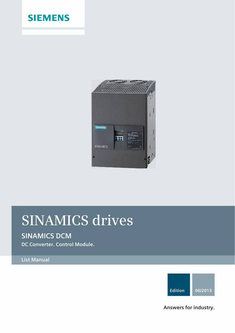
List Manual
Edition 06/2013
DC Converter. Control Module.
SINAMICS drivesSINAMICS DCM
Answers for industry.

06/2013
SINAMICS
SINAMICS DCM
List Manual
Valid for
Drive Firmware version
SINAMICS DCM 1.4 (based on 4.6)
6RX1800-0ED76
s
C98130-A7066-A3-4-7619
Preface
Parameters1
Function diagrams2
Faults and alarms3
AppendixA
List of abbreviationsB
IndexC

Copyright Siemens AG 2009 - 2013 All Rights Reserved
The reproduction, transmission, or use of this document or its con-tents is not permitted without express written permission. Offenders are liable to the payment of damages. All rights reserved, especially those relating to granting patents or GM registration.
Siemens AGIndustry SectorP.O. Box 484890327 NUREMBERGGERMANY
Liability Disclaimer
We have checked that the contents of this document correspond to the hardware and software described. Nevertheless, we cannot as-sume responsibility for any deviations that may occur. The data in this document is regularly checked and any necessary corrections includ-ed in subsequent editions.
© Siemens AG 2009 - 2013Subject to technical changes without prior notice.
Safety notices
This manual contains information that you should observe to ensure your own personal safety as well as to avoid material damage. The notes referring to your personal safety are highlighted by a warning trian-gle; notes that only relate to material damage have no warning triangle. The notes shown below are graded according to the level of hazard (from most to least hazardous):
If more than one level of danger is simultaneously applicable, the warning notice for the highest level is used. A warning note in a warning triangle indicating possible personal injury may also include a warning note relating to material damage.
Qualified personnel
The associated device/system may only be installed and operated in conjunction with this documentation. The device/system may only be commissioned and operated by qualified personnel. For the purpose of the safety information in this documentation, a "qualified person" is someone who is authorized to com-mission, ground, and tag equipment, systems, and circuits in accordance with established safety proce-dures.
Proper use of Siemens products
Please observe the following:
Trademarks
All names identified with ® are registered trademarks of Siemens AG. Any other names used in this pub-lication may be trademarks whose use by third parties for their own purposes could violate the rights of the owner.
Danger
Indicates that death or serious injury will result if proper precautions are not taken.
Warning
Indicates that death or serious injury may result if proper precautions are not taken.
Caution
With a warning triangle, indicates that minor injury may result if proper precautions are not taken.
Caution
Without a warning triangle, indicates that material damage may result if proper precautions are not taken.
Notice
Indicates that an undesirable result or condition may occur if the corresponding note is not observed.
Warning
Siemens products are only permitted to be used for the applications listed in the catalog and in the asso-ciated technical documentation. If third-party products and components are used, then they must be rec-ommended or approved by Siemens. These products can only function correctly and safely if they are transported, stored, set up, mounted, installed, commissioned, operated and maintained correctly. The permissible ambient conditions must be adhered to. Information in the associated documentation must be observed.
Siemens Aktiengesellschaft SINAMICS DCM List Manual (LH8)

Preface-5© Siemens AG 2009 - 2013 All Rights ReservedSINAMICS DCM List Manual (LH8), 06/2013, 6RX1800-0ED76
Preface
Information about documentation for SINAMICS
The SINAMICS documentation is structured according to the following catego-ries:
• General documentation / catalogs
• Manufacturer / service documentation
This documentation is part of the Technical Customer Documentation developed for SINAMICS.
In the interests of clarity, this documentation does not contain all the detailed information for all product types and cannot take into account every possible aspect of installation, operation, or maintenance.
The contents of this documentation are not part of an earlier or existing agree-ment, a promise, or a legal agreement, nor do they change this. All obligations on the part of Siemens can be found in the respective sales contract, which also con-tains the complete and sole warranty provisions. These contractual warranty pro-visions are neither extended nor restricted as a result of the statements made in this documentation.
Target group
This documentation addresses commissioning engineers and service personnel who use SINAMICS.
Objective
This manual contains information about all parameters, function diagrams, faults, and alarms required to commission and service the system.
This manual should be used in addition to the other manuals and tools provided for the product.
Search tools
The following guides are provided to help you locate information in this manual:
1. Table of contents
− General table of contents for the complete manual (after the preface).
− Table of contents for function diagrams (Chapter 2.1).
2. List of abbreviations
3. Index

Preface
Preface-6 © Siemens AG 2009 - 2013 All Rights ReservedSINAMICS DCM List Manual (LH8), 06/2013, 6RX1800-0ED76
Technical Support
Country-specific telephone numbers for technical support are provided on the Internet at:
http://www.siemens.com/automation/service&support
SINAMICS
You can find information on SINAMICS at:
http://www.siemens.com/sinamics

Contents-7© Siemens AG 2009 - 2013 All Rights ReservedSINAMICS DCM List Manual (LH8), 06/2013, 6RX1800-0ED76
Table of contents
1 Parameters . . . . . . . . . . . . . . . . . . . . . . . . . . . . . . . . . . . . . . . . . . . . . . . . . . . . . 1-9
1.1 Overview of parameters . . . . . . . . . . . . . . . . . . . . . . . . . . . . . . . . . . . . 1-101.1.1 Explanation of the list of parameters . . . . . . . . . . . . . . . . . . . . . . . . . . . 1-101.1.2 Number ranges of parameters . . . . . . . . . . . . . . . . . . . . . . . . . . . . . . . 1-22
1.2 List of parameters . . . . . . . . . . . . . . . . . . . . . . . . . . . . . . . . . . . . . . . . . 1-25
1.3 Parameters for data sets . . . . . . . . . . . . . . . . . . . . . . . . . . . . . . . . . . . . 1-6451.3.1 Parameters for command data sets (CDS) . . . . . . . . . . . . . . . . . . . . . . 1-6451.3.2 Parameters for drive data sets (DDS) . . . . . . . . . . . . . . . . . . . . . . . . . . 1-6471.3.3 Parameters for encoder data sets (EDS) . . . . . . . . . . . . . . . . . . . . . . . 1-653
1.4 Parameters for write protection and know-how protection . . . . . . . . . . 1-6551.4.1 Parameters with "WRITE_NO_LOCK" . . . . . . . . . . . . . . . . . . . . . . . . . 1-6551.4.2 Parameters with "KHP_WRITE_NO_LOCK". . . . . . . . . . . . . . . . . . . . . 1-6571.4.3 Parameters with "KHP_ACTIVE_READ" . . . . . . . . . . . . . . . . . . . . . . . 1-658
2 Function diagrams . . . . . . . . . . . . . . . . . . . . . . . . . . . . . . . . . . . . . . . . . . . . . . . 2-659
2.1 Table of contents. . . . . . . . . . . . . . . . . . . . . . . . . . . . . . . . . . . . . . . . . . 2-660
2.2 Explanation of the function diagrams . . . . . . . . . . . . . . . . . . . . . . . . . . 2-666
2.3 Overviews . . . . . . . . . . . . . . . . . . . . . . . . . . . . . . . . . . . . . . . . . . . . . . . 2-671
2.4 CUD input/output terminals . . . . . . . . . . . . . . . . . . . . . . . . . . . . . . . . . . 2-679
2.5 PROFIdrive . . . . . . . . . . . . . . . . . . . . . . . . . . . . . . . . . . . . . . . . . . . . . . 2-690
2.6 Internal control/status words . . . . . . . . . . . . . . . . . . . . . . . . . . . . . . . . . 2-715
2.7 Sequence control . . . . . . . . . . . . . . . . . . . . . . . . . . . . . . . . . . . . . . . . . 2-722
2.8 Brake control . . . . . . . . . . . . . . . . . . . . . . . . . . . . . . . . . . . . . . . . . . . . . 2-727
2.9 Setpoint channel . . . . . . . . . . . . . . . . . . . . . . . . . . . . . . . . . . . . . . . . . . 2-729
2.10 Encoder evaluation . . . . . . . . . . . . . . . . . . . . . . . . . . . . . . . . . . . . . . . . 2-743
2.11 Armature circuit closed-loop control . . . . . . . . . . . . . . . . . . . . . . . . . . . 2-751
2.12 Field circuit closed-loop control . . . . . . . . . . . . . . . . . . . . . . . . . . . . . . . 2-774
2.13 Power unit . . . . . . . . . . . . . . . . . . . . . . . . . . . . . . . . . . . . . . . . . . . . . . . 2-783
2.14 Technology controller . . . . . . . . . . . . . . . . . . . . . . . . . . . . . . . . . . . . . . 2-792
2.15 Signals and monitoring functions . . . . . . . . . . . . . . . . . . . . . . . . . . . . . 2-794
2.16 Faults and alarms . . . . . . . . . . . . . . . . . . . . . . . . . . . . . . . . . . . . . . . . . 2-811
2.17 Data sets . . . . . . . . . . . . . . . . . . . . . . . . . . . . . . . . . . . . . . . . . . . . . . . . 2-816
2.18 Communication between devices . . . . . . . . . . . . . . . . . . . . . . . . . . . . . 2-820
2.19 Terminal Module 15 for SINAMICS (TM15DI/DO) . . . . . . . . . . . . . . . . 2-826
2.20 Terminal Module 31 (TM31) . . . . . . . . . . . . . . . . . . . . . . . . . . . . . . . . . 2-830

Table of contents
Contents-8 © Siemens AG 2009 - 2013 All Rights ReservedSINAMICS DCM List Manual (LH8), 06/2013, 6RX1800-0ED76
2.21 Terminal Module 150 (TM150) . . . . . . . . . . . . . . . . . . . . . . . . . . . . . . . 2-841
2.22 Basic Operator Panel 20 (BOP20) . . . . . . . . . . . . . . . . . . . . . . . . . . . . 2-845
3 Faults and alarms . . . . . . . . . . . . . . . . . . . . . . . . . . . . . . . . . . . . . . . . . . . . . . . . 3-847
3.1 Overview of faults and alarms . . . . . . . . . . . . . . . . . . . . . . . . . . . . . . . . 3-8483.1.1 General information on faults and alarms . . . . . . . . . . . . . . . . . . . . . . . 3-8483.1.2 Explanation of the list of faults and alarms . . . . . . . . . . . . . . . . . . . . . . 3-8523.1.3 Number ranges of faults and alarms . . . . . . . . . . . . . . . . . . . . . . . . . . . 3-855
3.2 List of faults and alarms . . . . . . . . . . . . . . . . . . . . . . . . . . . . . . . . . . . . 3-857
A Appendix . . . . . . . . . . . . . . . . . . . . . . . . . . . . . . . . . . . . . . . . . . . . . . . . . . . . . . . A-1141
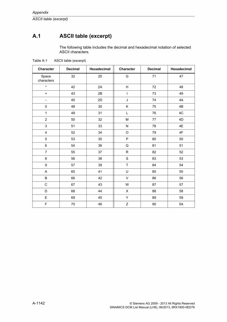
A.1 ASCII table (excerpt) . . . . . . . . . . . . . . . . . . . . . . . . . . . . . . . . . . . . . . . A-1142
B List of abbreviations. . . . . . . . . . . . . . . . . . . . . . . . . . . . . . . . . . . . . . . . . . . . . . B-1143
C Index . . . . . . . . . . . . . . . . . . . . . . . . . . . . . . . . . . . . . . . . . . . . . . . . . . . . . . . . . . C-1153

1-9© Siemens AG 2009 - 2013 All Rights ReservedSINAMICS DCM List Manual (LH8), 06/2013, 6RX1800-0ED76
Parameters 1Content
1.1 Overview of parameters 1-10
1.2 List of parameters 1-25
1.3 Parameters for data sets 1-645
1.4 Parameters for write protection and know-how protection 1-655

Parameters
Overview of parameters
1-10 © Siemens AG 2009 - 2013 All Rights ReservedSINAMICS DCM List Manual (LH8), 06/2013, 6RX1800-0ED76
1.1 Overview of parameters
1.1.1 Explanation of the list of parameters
Basic structure of the parameter descriptions
The data in the following example have been chosen at random. The description of a parameter includes as a maximum, the information listed below. Some of the information is optional.
The parameter list (See Chapter 1.2) is structured as follows:
- - - - - - - - - - - - - - - - - - - - Start of the example - - - - - - - - - - - - - - - - - - - - - - - - - - - - - - - - - - - - - - - - - - - - - - - - - -
Description: Text
Values: 0: Name and meaning of value 01: Name and meaning of value 12: Name and meaning of value 2etc.
Recommend.: Text
Index: [0] = Name and meaning of index 0[1] = Name and meaning of index 1[2] = Name and meaning of index 2etc.
Dependency: TextSee also: pxxxx, rxxxxSee also: Fxxxxx, Axxxxx
Note: Information that might be useful.
- - - - - - - - - - - - - - - - - - - - End of the example - - - - - - - - - - - - - - - - - - - - - - - - - - - - - - - - - - - - - - - - - - - - - - - - - - -
pxxxx[0...n] BICO: Full parameter name / abbreviated nameDrive object (function module)
Can be changed: C1(x), C2(x), U, T Calculated: CALC_MOD_REG Access level: 2
Data type: Unsigned32 / Integer16 Dynamic index: CDS, p0170 Function diagram: 2080
P group: Closed-loop control Unit group: 7_1 Unit selection: p0505
Not for motor type: FEM Normalizing: p2000 Expert list: 1
Min Max Factory setting0.00 [Nm] 10.00 [Nm] 0.00 [Arms]
Bit array: Bit Signal name 1 signal 0 signal FP00 Name and meaning of bit 0 Yes No 801001 Name and meaning of bit 1 Yes No -02 Name and meaning of bit 2 Yes No 8012
etc.
Danger: Warning: Caution: Safety notices with a warning triangle
Caution: Notice: Safety notices without a warning triangle

Overview of parameters
Parameters
1-11© Siemens AG 2009 - 2013 All Rights ReservedSINAMICS DCM List Manual (LH8), 06/2013, 6RX1800-0ED76
pxxxx[0...n] Parameter number
The parameter number is made up of a “p” or “r”, followed by the parameter num-ber and the index (optional).
Examples of the representation in the parameter list:
Other examples of the notation used in the documentation:
The following applies to adjustable parameters:
The parameter value “when shipped” is specified under “Factory setting” with the relevant unit in square parentheses. The value can be adjusted within the range defined by “Min” and “Max”.
The term "linked parameterization" is used in cases where changes to adjustable parameters affect the settings of other parameters.
Linked parameterization can occur, for example, as a result of the following actions and parameters:
• Executing macros
p0015, p0700, p1000, p1500
• Setting a PROFIBUS telegram (BICO interconnections)
p0922
• Setting component lists
p0400
• Automatically calculating and preassigning
p0112, p0340, p3900
• Restore factory settings
p0970
• p... Adjustable parameters (read and write parameters)
• r... Display parameters (read-only)
• p0918 Adjustable parameter 918
• p0099[0...3] Adjustable parameter 99, indices 0 to 3
• p1001[0...n] Adjustable parameter 1001, indices 0 to n (n = configurable)
• r0944 Display parameter 944
• r2129.0...15 Display parameter 2129 with bit array from bit 0 (smallest bit) to bit 15 (largest bit)
• p1070[1] Adjustable parameter 1070, index 1
• p2098[1].3 Adjustable parameter 2098, index 1 bit 3
• r0945[2](3) Display parameter 945, index 2 of drive object 3
• p0795.4 Adjustable parameter 795, bit 4

Parameters
Overview of parameters
1-12 © Siemens AG 2009 - 2013 All Rights ReservedSINAMICS DCM List Manual (LH8), 06/2013, 6RX1800-0ED76
The following applies to display parameters:
The fields “Min”, “Max” and “Factory setting” are specified with a dash “-” and the relevant unit in square parentheses.
BICO: Full parameter name / abbreviated name
The following abbreviations can appear in front of the parameter name:
Drive object (function module)
A drive object (DO) is an independent, "self-contained" functional unit that has its own parameters and, in some cases, faults and alarms.
When carrying out commissioning using the commissioning software, you can select/deselect additional functions and their parameters by activating/deactivat-ing function modules accordingly.
The parameter list specifies the associated drive object and function module for each individual parameter.
Note:
The parameter list can contain parameters that are not visible in the expert lists of the respective commissioning software (e.g. parameters for trace functions).
• BI: Binector Input This parameter is used for selecting the source of a digital signal.
• BO: Binector Output This parameter is available as a digital signal for interconnection with other parameters.
• CI: Connector Input This parameter is used for selecting the source of an “analog” sig-nal.
• CO: Connector Output This parameter is available as an “analog” signal for interconnec-tion with other parameters.
• CO/BO: Connector/Binector Output This parameter is available as an “analog” and digital signal for interconnection with other parameters.
Note:
A connector input (CI) cannot be just interconnected with any connector output (CO, signal source).When interconnecting a connector input using the commissioning software, only the corresponding possible signal sources are listed.

Overview of parameters
Parameters
1-13© Siemens AG 2009 - 2013 All Rights ReservedSINAMICS DCM List Manual (LH8), 06/2013, 6RX1800-0ED76
Example:
• r61000: PROFINET Name of StationCU_DC (PROFINET)The parameter is only available in the case of the CU_DC drive object with the “PROFINET” function module.
A parameter can belong to a single, multiple, or all drive objects.
The following information relating to “Drive object” and “Function module” can be displayed under the parameter number:
Table 1-1 Data in the “Drive object (function module)” field
Drive object (function module)
Type Meaning
All objects - This parameter is used by all drive objects.
CU_DC 6 Advanced Control Unit SINAMICS DCM (CUD) is to the left.
CU_DC_R 6 Advanced Control Unit SINAMICS DCM (CUD) is to the right.
CU_DC_S 6 Standard Control Unit SINAMICS DCM (CUD) is to the left.
CU_DC_R_S 6 Standard Control Unit SINAMICS DCM (CUD) is to the right.
CU_DC (PROFINET) - Control Unit SINAMICS DCM with "PROFINET" function module
DC_CTRL 17 DC closed loop control general or DC closed loop control on the Advanced CUD left.
DC_CTRL_R 17 DC closed loop control extended on the Advanced CUD right.
DC_CTRL_S 17 DC closed loop control on the standard CUD right.
DC_CTRL_R_S 17 DC closed loop control extended on the standard CUD right.
DC_CTRL (PROFINET) - DC closed loop control with "PROFINET" function module.
TM31 200 Terminal Module 31.
TM31 (PROFINET) - Terminal Module 31 with "PROFINET" function module.
TM15DI_DO 204 Terminal Module 15 (for SINAMICS).
TM15DI_DO (PROFINET) - Terminal Module 15 (for SINAMICS) with "PROFINET" function module.
TM150 208 Terminal Module 150.
TM150 (PROFINET) - Terminal Module 150 with "PROFINET" function module.
Note:
The drive object type is used to identify the drive objects in the drive system (e.g. r0107, r0975[1]).

Parameters
Overview of parameters
1-14 © Siemens AG 2009 - 2013 All Rights ReservedSINAMICS DCM List Manual (LH8), 06/2013, 6RX1800-0ED76
Can be changed
The “-” sign indicates that the parameter can be changed in any object state and that the change will be effective immediately.
The information “C1(x), C2(x), T, U” ((x): optional) means that the parameter can be changed only in the specified drive object state and that the change will not take effect until the object switches to another state. This can be one or more states.
The following states exist:
• C1(x) Device commissioning C1: Commissioning 1
Device commissioning is in progress (p0009 > 0).
Pulses cannot be enabled.
The parameter can only be changed for the following device commis-sioning settings (p0009 > 0):
• C1: Can be changed for all settings p0009 > 0.
• C1(x): Can be changed only when p0009 = x.
A modified parameter value does not take effect until device commissioning mode is exited with p0009 = 0.
• C2(x) Drive object commissioning C2: Commissioning 2
Drive commissioning is in progress (p0009 = 0 and p0010 > 0).
Pulses cannot be enabled.
The parameter can only be changed in the following drive commission-ing settings (p0010 > 0):
• C2: Can be changed for all settings p0010 > 0.
• C2(x): Can only be changed for the settings p0010 = x.
A modified parameter value does not take effect until drive commissioning mode is exited with p0010 = 0.
• U Operation U: Run
Pulses are enabled.
• T Ready T: Ready to run
The pulses are not enabled and the “C1(x)” or “C2(x)” state is not active.
Note:
Parameter p0009 is CU-specific (belongs to the Control Unit).
Parameter p0010 is drive-specific (belongs to each drive object).
The operating state of individual drive objects is displayed in r0002.

Overview of parameters
Parameters
1-15© Siemens AG 2009 - 2013 All Rights ReservedSINAMICS DCM List Manual (LH8), 06/2013, 6RX1800-0ED76
Calculated
Specifies whether the parameter is influenced by automatic calculations.
The calculation attribute defines which activities influence the parameter.
The following attributes exist:
• CALC_MOD_ALL
− p0340 = 1
• CALC_MOD_CON
− p0340 = 1
• CALC_MOD_EQU
− p0340 = 1
• CALC_MOD_LIM_REF
− p0340 = 1, 5
• CALC_MOD_REG
− p0340 = 1, 3
Access level
Specifies the access level required to be able to display and change this param-eter. The required access level can be set using p0003.
The system uses the following access levels:
• 1: Standard
• 2: Extended
• 3: Expert
• 4: ServiceParameters with this access level are password protected.
Note:
For p3900 > 0, p0340 = 1 is also called automatically.
Note:
Parameter p0003 is CU-specific (belongs to the Control Unit).
Parameters
Overview of parameters
1-16 © Siemens AG 2009 - 2013 All Rights ReservedSINAMICS DCM List Manual (LH8), 06/2013, 6RX1800-0ED76
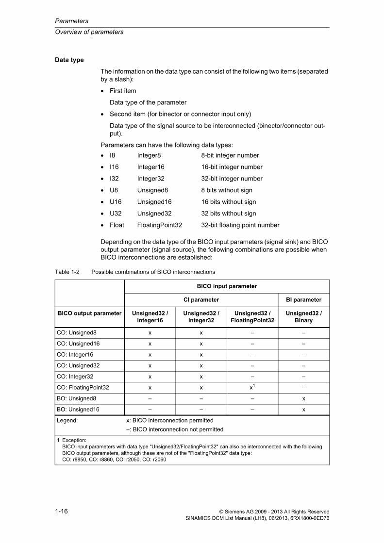
Data type
The information on the data type can consist of the following two items (separated by a slash):
• First item
Data type of the parameter
• Second item (for binector or connector input only)
Data type of the signal source to be interconnected (binector/connector out-put).
Parameters can have the following data types:
Depending on the data type of the BICO input parameters (signal sink) and BICO output parameter (signal source), the following combinations are possible when BICO interconnections are established:
• I8 Integer8 8-bit integer number
• I16 Integer16 16-bit integer number
• I32 Integer32 32-bit integer number
• U8 Unsigned8 8 bits without sign
• U16 Unsigned16 16 bits without sign
• U32 Unsigned32 32 bits without sign
• Float FloatingPoint32 32-bit floating point number
Table 1-2 Possible combinations of BICO interconnections
BICO input parameter
CI parameter BI parameter
BICO output parameter Unsigned32 / Integer16
Unsigned32 / Integer32
Unsigned32 / FloatingPoint32
Unsigned32 / Binary
CO: Unsigned8 x x – –
CO: Unsigned16 x x – –
CO: Integer16 x x – –
CO: Unsigned32 x x – –
CO: Integer32 x x – –
CO: FloatingPoint32 x x x1 –
BO: Unsigned8 – – – x
BO: Unsigned16 – – – x
Legend: x: BICO interconnection permitted
–: BICO interconnection not permitted
1 Exception:BICO input parameters with data type "Unsigned32/FloatingPoint32" can also be interconnected with the following BICO output parameters, although these are not of the "FloatingPoint32" data type:CO: r8850, CO: r8860, CO: r2050, CO: r2060

Overview of parameters
Parameters
1-17© Siemens AG 2009 - 2013 All Rights ReservedSINAMICS DCM List Manual (LH8), 06/2013, 6RX1800-0ED76
Dynamic index
For parameters with a dynamic index [0 to n], the following information is specified here:
• Data set (if this is available).
• Parameter for the number of indices (n = number - 1).
The following information can be contained in this field:
• “CDS, p0170” (Command Data Set, CDS count)
Example:
p1070[0] main setpoint [command data set 0]
p1070[1] main setpoint [command data set 1], etc.
• “DDS, p0180” (Drive Data Set, DDS count)
• “EDS, p0140” (Encoder Data Set, EDS count)
BO: Integer16 – – – x
BO: Unsigned32 – – – x
BO: Integer32 – – – x
BO: FloatingPoint32 – – – –
Table 1-2 Possible combinations of BICO interconnections, continued
BICO input parameter
CI parameter BI parameter
BICO output parameter Unsigned32 / Integer16
Unsigned32 / Integer32
Unsigned32 / FloatingPoint32
Unsigned32 / Binary
Legend: x: BICO interconnection permitted
–: BICO interconnection not permitted
1 Exception:BICO input parameters with data type "Unsigned32/FloatingPoint32" can also be interconnected with the following BICO output parameters, although these are not of the "FloatingPoint32" data type:CO: r8850, CO: r8860, CO: r2050, CO: r2060
Note:
Information on the data sets can be taken from the following references:
References: SINAMICS DC MASTER operating instructions“Data sets” Chapter
Parameters
Overview of parameters
1-18 © Siemens AG 2009 - 2013 All Rights ReservedSINAMICS DCM List Manual (LH8), 06/2013, 6RX1800-0ED76
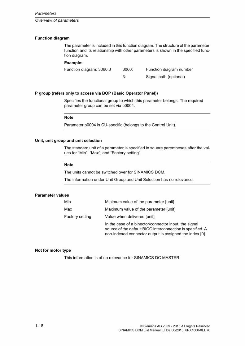
Function diagram
The parameter is included in this function diagram. The structure of the parameter function and its relationship with other parameters is shown in the specified func-tion diagram.
Example:
P group (refers only to access via BOP (Basic Operator Panel))
Specifies the functional group to which this parameter belongs. The required parameter group can be set via p0004.
Unit, unit group and unit selection
The standard unit of a parameter is specified in square parentheses after the val-ues for “Min”, “Max”, and “Factory setting”.
Parameter values
Not for motor type
This information is of no relevance for SINAMICS DC MASTER.
Function diagram: 3060.3 3060: Function diagram number
3: Signal path (optional)
Note:
Parameter p0004 is CU-specific (belongs to the Control Unit).
Note:
The units cannot be switched over for SINAMICS DCM.
The information under Unit Group and Unit Selection has no relevance.
Min Minimum value of the parameter [unit]
Max Maximum value of the parameter [unit]
Factory setting Value when delivered [unit]
In the case of a binector/connector input, the signal source of the default BICO interconnection is specified. A non-indexed connector output is assigned the index [0].

Overview of parameters
Parameters
1-19© Siemens AG 2009 - 2013 All Rights ReservedSINAMICS DCM List Manual (LH8), 06/2013, 6RX1800-0ED76
Normalizing
Specification of the reference variable with which a signal value is automatically converted for a BICO interconnection.
The following reference variables are possible:
• p2000 ... p2007: Reference speed, reference voltage, etc.
• PERCENT: 1.0 = 100 %
• 4000H: 4000 hex = 100 %
Expert list
Specifies whether this parameter is available in the expert list of the specified drive objects in the commissioning software.
1: Parameter does exist in the expert list.
0: Parameter does not exist in the expert list.
Description
Explanation of a parameter function.
Values
List of the possible values of a parameter.
Recommendation
Information about recommended settings.
Notice:
Users are responsible for using parameters that are marked “Expert list: 0” (parameter not included in the expert list).
These parameters and their functionalities have not been tested and no further user documentation is available for them (e.g. description of functions). Moreover, "Technical Support" (hotline) does not provide any support for these parameters.

Parameters
Overview of parameters
1-20 © Siemens AG 2009 - 2013 All Rights ReservedSINAMICS DCM List Manual (LH8), 06/2013, 6RX1800-0ED76
Index
The name and meaning of each individual index is specified for indexed parame-ters.
The following applies to the values (Min, Max, Factory setting) of indexed adjust-able parameters:
• Min, Max:
The adjustment range and unit apply to all indices.
• Factory setting:
When all indices have the same factory setting, index 0 is specified with the unit to represent all indices.
When the indices have different factory settings, they are all listed individually with the unit.
Bit array
For parameters with bit arrays, the following information is provided about each bit:
• Bit number and signal name
• Meaning for signal states 0 and 1
• Function diagram (optional)
The signal is shown in this function diagram.
Dependency
Conditions that must be fulfilled in conjunction with this parameter. Also includes special effects that can occur between this parameter and others.
See also: List of other additional parameters to be considered.

Overview of parameters
Parameters
1-21© Siemens AG 2009 - 2013 All Rights ReservedSINAMICS DCM List Manual (LH8), 06/2013, 6RX1800-0ED76
Safety notices
Important information that must be observed to avoid the risk of physical injury or material damage.
Information that must be observed to avoid any problems.
Information that the user may find useful.
Danger The description of this safety notice can be found at the beginning of this manual (see Safety notices).
Warning The description of this safety notice can be found at the beginning of this manual (see Safety notices).
Caution The description of this safety notice can be found at the beginning of this manual (see Safety notices).
Caution The description of this safety notice can be found at the beginning of this manual (see Safety notices).
Notice The description of this safety notice can be found at the beginning of this manual (see Safety notices).
Note Information that the user may find useful.

Parameters
Overview of parameters
1-22 © Siemens AG 2009 - 2013 All Rights ReservedSINAMICS DCM List Manual (LH8), 06/2013, 6RX1800-0ED76
1.1.2 Number ranges of parameters
Number ranges for SINAMICS in general
Parameters are grouped into the following number ranges:
Note:
The following number ranges represent an overview of all parameters associated with the SINAMICS drive range.
The parameters for the product described in this List Manual are described in detail in Chapter 1.2.
Table 1-3 Number ranges for SINAMICS
Range Description
from to
0000 0099 Display and operation
0100 0199 Commissioning
0200 0299 Power unit
0300 0399 Motor
0400 0499 Encoder
0500 0599 Technology and units, motor-specific data, probes
0600 0699 Thermal monitoring, maximum current, operating hours, motor data, central probe
0700 0799 Control Unit terminals, measuring sockets
0800 0839 CDS, DDS data sets, motor changeover
0840 0879 Sequence control (e.g. signal source for ON/OFF1)
0880 0899 ESR, parking, control and status words
0900 0999 PROFIBUS/PROFIdrive
1000 1199 Setpoint channel (e.g. ramp-function generator)
1200 1299 Functions (e.g. motor holding brake)
1300 1399 V/f control
1400 1799 Closed-loop control
1800 1899 Gating unit
1900 1999 Power unit and motor identification
2000 2009 Reference values
2010 2099 Communication (fieldbus)
2100 2139 Faults and alarms
2140 2199 Signals and monitoring
2200 2359 Technology controller

Overview of parameters
Parameters
1-23© Siemens AG 2009 - 2013 All Rights ReservedSINAMICS DCM List Manual (LH8), 06/2013, 6RX1800-0ED76
2360 2399 Staging, hibernation
2500 2699 Position control (LR) and basic positioning (EPOS)
2700 2719 Reference values, display
2720 2729 Load gearbox
2800 2819 Logic operations
2900 2930 Fixed values (e.g. percentage, torque)
3000 3099 Motor identification results
3100 3109 Real time clock (RTC)
3110 3199 Faults and alarms
3200 3299 Signals and monitoring
3400 3659 Infeed closed-loop control
3660 3699 Voltage Sensing Module (VSM), Braking Module internal
3700 3779 Advanced Positioning Control (APC)
3780 3819 Synchronization
3820 3849 Friction characteristic
3850 3899 Functions (e.g. long stator)
3900 3999 Administration
4000 4599 Terminal Board, Terminal Module (e.g. TB30, TM31)
4600 4699 Sensor Module
4700 4799 Trace
4800 4849 Function generator
4950 4999 OA application
5000 5169 Spindle diagnostics
5200 5230 Current setpoint filter 5 ... 10 (r0108.21)
5400 5499 Line droop control (e.g. shaft generator)
5500 5599 Dynamic grid support (solar)
5600 5613 PROFIenergy
5900 6999 SINAMICS GM/SM/GL/SL
7000 7499 Parallel connection of power units
7500 7599 SINAMICS SM120
7700 7729 External messages
7770 7789 NVRAM, system parameters
7800 7839 EEPROM read/write parameters
7840 8399 Internal system parameters
Table 1-3 Number ranges for SINAMICS, continued
Range Description
from to

Parameters
Overview of parameters
1-24 © Siemens AG 2009 - 2013 All Rights ReservedSINAMICS DCM List Manual (LH8), 06/2013, 6RX1800-0ED76
8400 8449 Real time clock (RTC)
8500 8599 Data and macro management
8600 8799 CAN bus
8800 8899 Communication Board Ethernet (CBE), PROFIdrive
8900 8999 Industrial Ethernet, PROFINET, CBE20
9000 9299 Topology
9300 9399 Safety Integrated
9400 9499 Parameter consistency and storage
9500 9899 Safety Integrated
9900 9949 Topology
9950 9999 Diagnostics, internal
10000 10199 Safety Integrated
11000 11299 Free technology controller 0, 1, 2
20000 20999 Free function blocks (FBLOCKS)
21000 25999 Drive Control Chart (DCC)
50000 53999 SINAMICS DC MASTER (DC closed-loop control)
61000 61001 PROFINET
Table 1-3 Number ranges for SINAMICS, continued
Range Description
from to

List of parameters
Parameters
1-25© Siemens AG 2009 - 2013 All Rights ReservedSINAMICS DCM List Manual (LH8), 06/2013, 6RX1800-0ED76
1.2 List of parameters
Product: SINAMICS DC MASTER, Version: 4601800, Language: engObjects: CU_DC, CU_DC_R, CU_DC_R_S, CU_DC_S, DC_CTRL, DC_CTRL_R, DC_CTRL_R_S, DC_CTRL_S, TM150, TM15DI_DO, TM31Product: SINAMICS DC MASTER OA, Version: 1400800, Language: engObjects: DC_CTRL
Description: Operating display for the Control Unit (CU).
Value: 0: Operation10: Ready20: Wait for run-up25: Wait for automatic FW update of DRIVE-CLiQ components31: Commissioning software download active33: Remove/acknowledge topology error34: Exit commissioning mode35: Carry out first commissioning70: Initialization80: Reset active99: Internal software error
Notice: For several missing enable signals, the corresponding value with the highest number is displayed.
Description: Operating display for the drive.
Value: 0: o0.0 No torque direction switched on1: o0.1 Torque direction I switched on2: o0.2 Torque direction II switched on9: o0.9 Wait for enable from master10: o1.0 Wait time for brake opening time running11: o1.1 Wait for operating enable at terminal 1312: o1.2 Wait for operating enable (signal source acc. to p0852)13: o1.3 Wait time after withdrawing a jog command running14: o1.4 Wait until the field has been reversed15: o1.5 Wait for operating enable from the optimization run16: o1.6 Wait for withdrawal of the immediate pulse inhibit17: o1.7 Wait for SINAMICS DCM connected in parallel in status o0.018: o1.8 Operating state o1.819: o1.9 Operating state o1.920: o2.0 Wait for setpoint21: o2.1 Operating state o2.122: o2.2 Operating state o2.230: o3.0 Wait for the thyristor check to be completed31: o3.1 Wait for line supply symmetry32: o3.2 Wait for a DC contactor to pick up33: o3.3 Wait for the feedback signal "main contactor"34: o3.4 Operating state o3.435: o3.5 Operating state o3.5
r0002 Control Unit operating display / CU op_displayCU_DC, CU_DC_R, CU_DC_R_S, CU_DC_S
Can be changed: - Calculated: - Access level: 1
Data type: Integer16 Dyn. index: - Func. diagram: 2651
P-Group: - Units group: - Unit selection: -
Not for motor type: - Scaling: - Expert list: 1
Min Max Factory setting 0 99 -
r0002 Drive operating display / Drv op_displayDC_CTRL, DC_CTRL_R, DC_CTRL_R_S, DC_CTRL_S
Can be changed: - Calculated: - Access level: 1
Data type: Integer16 Dyn. index: - Func. diagram: 2651
P-Group: - Units group: - Unit selection: -
Not for motor type: - Scaling: - Expert list: 1
Min Max Factory setting 0 129 -
Parameters
List of parameters
1-26 © Siemens AG 2009 - 2013 All Rights ReservedSINAMICS DCM List Manual (LH8), 06/2013, 6RX1800-0ED76
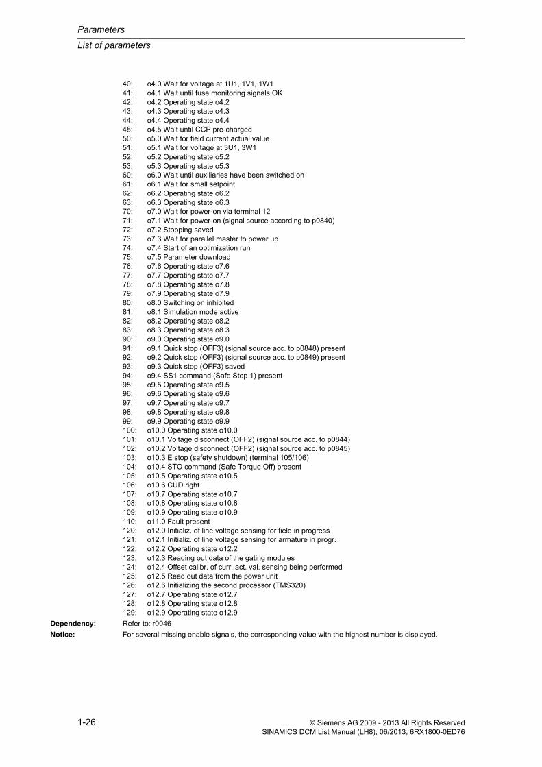
40: o4.0 Wait for voltage at 1U1, 1V1, 1W141: o4.1 Wait until fuse monitoring signals OK42: o4.2 Operating state o4.243: o4.3 Operating state o4.344: o4.4 Operating state o4.445: o4.5 Wait until CCP pre-charged50: o5.0 Wait for field current actual value51: o5.1 Wait for voltage at 3U1, 3W152: o5.2 Operating state o5.253: o5.3 Operating state o5.360: o6.0 Wait until auxiliaries have been switched on61: o6.1 Wait for small setpoint62: o6.2 Operating state o6.263: o6.3 Operating state o6.370: o7.0 Wait for power-on via terminal 1271: o7.1 Wait for power-on (signal source according to p0840)72: o7.2 Stopping saved73: o7.3 Wait for parallel master to power up74: o7.4 Start of an optimization run75: o7.5 Parameter download76: o7.6 Operating state o7.677: o7.7 Operating state o7.778: o7.8 Operating state o7.879: o7.9 Operating state o7.980: o8.0 Switching on inhibited81: o8.1 Simulation mode active82: o8.2 Operating state o8.283: o8.3 Operating state o8.390: o9.0 Operating state o9.091: o9.1 Quick stop (OFF3) (signal source acc. to p0848) present92: o9.2 Quick stop (OFF3) (signal source acc. to p0849) present93: o9.3 Quick stop (OFF3) saved94: o9.4 SS1 command (Safe Stop 1) present95: o9.5 Operating state o9.596: o9.6 Operating state o9.697: o9.7 Operating state o9.798: o9.8 Operating state o9.899: o9.9 Operating state o9.9100: o10.0 Operating state o10.0101: o10.1 Voltage disconnect (OFF2) (signal source acc. to p0844)102: o10.2 Voltage disconnect (OFF2) (signal source acc. to p0845)103: o10.3 E stop (safety shutdown) (terminal 105/106)104: o10.4 STO command (Safe Torque Off) present105: o10.5 Operating state o10.5106: o10.6 CUD right107: o10.7 Operating state o10.7108: o10.8 Operating state o10.8109: o10.9 Operating state o10.9110: o11.0 Fault present120: o12.0 Initializ. of line voltage sensing for field in progress121: o12.1 Initializ. of line voltage sensing for armature in progr.122: o12.2 Operating state o12.2123: o12.3 Reading out data of the gating modules124: o12.4 Offset calibr. of curr. act. val. sensing being performed125: o12.5 Read out data from the power unit126: o12.6 Initializing the second processor (TMS320)127: o12.7 Operating state o12.7128: o12.8 Operating state o12.8129: o12.9 Operating state o12.9
Dependency: Refer to: r0046
Notice: For several missing enable signals, the corresponding value with the highest number is displayed.

List of parameters
Parameters
1-27© Siemens AG 2009 - 2013 All Rights ReservedSINAMICS DCM List Manual (LH8), 06/2013, 6RX1800-0ED76
Note: OC: Operating condition
RFG: Ramp-function generator
COMM: Commissioning
Description: Operating display for Terminal Module 150 (TM150)
Value: 0: Module in cyclic operation40: Module not in cyclic operation50: Alarm60: Fault70: Initialization120: Module de-activated200: Wait for booting/partial booting250: Device signals a topology error
Notice: For several missing enable signals, the corresponding value with the highest number is displayed.
Description: Operating display for Terminal Module 15 (TM15).
Value: 0: Module in cyclic operation40: Module not in cyclic operation50: Alarm60: Fault70: Initialization120: Module de-activated200: Wait for booting/partial booting250: Device signals a topology error
Notice: For several missing enable signals, the corresponding value with the highest number is displayed.
Description: Operating display for Terminal Module 31 (TM31).
Value: 0: Module in cyclic operation40: Module not in cyclic operation50: Alarm60: Fault70: Initialization120: Module de-activated200: Wait for booting/partial booting250: Device signals a topology error
r0002 TM150 operating display / TM150 op_displayTM150 Can be changed: - Calculated: - Access level: 1
Data type: Integer16 Dyn. index: - Func. diagram: -
P-Group: - Units group: - Unit selection: -
Not for motor type: - Scaling: - Expert list: 1
Min Max Factory setting 0 250 -
r0002 TM15DI/DO operating display / TM15D op_displayTM15DI_DO Can be changed: - Calculated: - Access level: 1
Data type: Integer16 Dyn. index: - Func. diagram: -
P-Group: - Units group: - Unit selection: -
Not for motor type: - Scaling: - Expert list: 1
Min Max Factory setting 0 250 -
r0002 TM31 operating display / TM31 op_displayTM31 Can be changed: - Calculated: - Access level: 1
Data type: Integer16 Dyn. index: - Func. diagram: -
P-Group: - Units group: - Unit selection: -
Not for motor type: - Scaling: - Expert list: 1
Min Max Factory setting 0 250 -

Parameters
List of parameters
1-28 © Siemens AG 2009 - 2013 All Rights ReservedSINAMICS DCM List Manual (LH8), 06/2013, 6RX1800-0ED76
Notice: For several missing enable signals, the corresponding value with the highest number is displayed.
Description: Sets the access level for reading and writing parameters via the Basic Operator Panel (BOP).
Value: 1: Standard2: Extended3: Expert4: Service
Note: A higher set access level also includes the lower one.
Access level 1 (standard):
Parameters for simplest possible operations.
Access level 2 (extended):
Parameters to operate the basic functions of the drive unit.
Access level 3 (experts):
Expert know-how is required for these parameters (e.g. BICO parameterization).
Access level 4 (service):
For these parameters, it is necessary that authorized service personnel enter the appropriate password (p3950).
Description: Sets the display filter for parameters with the Basic Operator Panel (BOP).
Value: 0: All parameters1: Displays, signals2: Power unit3: Motor4: Encoder/pos enc5: Technology/units7: Digital inputs/outputs, commands, sequence control12: Functions14: Control15: Data sets20: Communication21: Faults, alarms, monitoring functions28: Free function blocks47: Trace and function generator50: OA parameters90: Topology98: Command Data Sets (CDS)99: Drive Data Sets (DDS)
Dependency: Refer to: p0003
Notice: The display filter via p0004 provides precise filtering and displays the corresponding parameters only when p0009 and p0010 = 0.
p0003 BOP access level / BOP acc_levelCU_DC, CU_DC_R, CU_DC_R_S, CU_DC_S
Can be changed: C1, U, T Calculated: - Access level: 1
Data type: Integer16 Dyn. index: - Func. diagram: -
P-Group: - Units group: - Unit selection: -
Not for motor type: - Scaling: - Expert list: 1
Min Max Factory setting 1 4 1
p0004 BOP display filter / BOP disp_filterCU_DC, CU_DC_R, CU_DC_R_S, CU_DC_S
Can be changed: C2(1), U, T Calculated: - Access level: 1
Data type: Integer16 Dyn. index: - Func. diagram: -
P-Group: - Units group: - Unit selection: -
Not for motor type: - Scaling: - Expert list: 1
Min Max Factory setting 0 99 0

List of parameters
Parameters
1-29© Siemens AG 2009 - 2013 All Rights ReservedSINAMICS DCM List Manual (LH8), 06/2013, 6RX1800-0ED76
Note: The set access level via p0003 is also relevant for the display filter via p0004.
Examples (assumption: p0009 = p0010 = 0):
p0003 = 1, p0004 = 3
--> Only the parameters for the motor with access level 1 are displayed.
p0003 = 2, p0004 = 3
--> Only the parameters for the motor with access levels 1 and 2 are displayed.
Description: Sets the parameter number and parameter index for display for p0006 = 4 for the Basic Operator Panel (BOP).
Index: [0] = Parameter number[1] = Parameter index
Dependency: Refer to: p0006
Note: Procedure:
1.
The parameter number to be displayed should be set in index 0. Only the monitoring parameters (read-only param-eters) can be set that actually exist for the actual drive object.
If the set parameter number is not indexed, or if there is an index in index 1 that lies outside the valid range of the set parameter, then index 1 is automatically set to 0.
2.
The index that belongs to the parameter set in index 0 should be set in index 1. The permissible changes in index 1 always depend on the parameter number set in index 0.
p0005[0...1] BOP operating display selection / BOP op_disp selCU_DC, CU_DC_R, CU_DC_R_S, CU_DC_S
Can be changed: U, T Calculated: - Access level: 2
Data type: Unsigned16 Dyn. index: - Func. diagram: -
P-Group: - Units group: - Unit selection: -
Not for motor type: - Scaling: - Expert list: 1
Min Max Factory setting 0 65535 [0] 2
[1] 0
p0005[0...1] BOP operating display selection / BOP op_disp selDC_CTRL, DC_CTRL_R, DC_CTRL_R_S, DC_CTRL_S
Can be changed: U, T Calculated: - Access level: 2
Data type: Unsigned16 Dyn. index: - Func. diagram: -
P-Group: - Units group: - Unit selection: -
Not for motor type: - Scaling: - Expert list: 1
Min Max Factory setting 0 65535 [0] 50000
[1] 0

Parameters
List of parameters
1-30 © Siemens AG 2009 - 2013 All Rights ReservedSINAMICS DCM List Manual (LH8), 06/2013, 6RX1800-0ED76
Description: Sets the parameter number and parameter index for display for p0006 = 2, 4 for the Basic Operator Panel (BOP).
Examples for the SERVO drive object:
p0005[0] = 21, p0005[1] = 0: Actual speed smoothed (r0021)
p0005[0] = 25, p0005[1] = 0: Output voltage smoothed (r0025)
Index: [0] = Parameter number[1] = Parameter index
Dependency: Refer to: p0006
Note: Procedure:
1.
The parameter number to be displayed should be set in index 0. Only the monitoring parameters (read-only param-eters) can be set that actually exist for the actual drive object.
If the set parameter number is not indexed, or if there is an index in index 1 that lies outside the valid range of the set parameter, then index 1 is automatically set to 0.
2.
The index that belongs to the parameter set in index 0 should be set in index 1. The permissible changes in index 1 always depend on the parameter number set in index 0.
Description: Sets the mode of the operating display for the Basic Operator Panel (BOP) in the operating states "ready for opera-tion" and "operation".
Value: 4: p0005
Dependency: Refer to: p0005
Note: Mode 4 is available for all drive objects.
Description: Sets the mode of the operating display for the Basic Operator Panel (BOP) in the operating states "ready for opera-tion" and "operation".
Value: 4: p0005
Dependency: Refer to: p0005
Note: Mode 0 ... 3 can only be selected if also r0020, r0021 are available on the drive object.
Mode 4 is available for all drive objects.
p0005[0...1] BOP operating display selection / BOP op_disp selTM150, TM15DI_DO, TM31
Can be changed: U, T Calculated: - Access level: 2
Data type: Unsigned16 Dyn. index: - Func. diagram: -
P-Group: - Units group: - Unit selection: -
Not for motor type: - Scaling: - Expert list: 1
Min Max Factory setting 0 65535 [0] 2
[1] 0
p0006 BOP operating display mode / BOP op_ disp modeCU_DC, CU_DC_R, CU_DC_R_S, CU_DC_S, DC_CTRL, DC_CTRL_R, DC_CTRL_R_S, DC_CTRL_S
Can be changed: U, T Calculated: - Access level: 3
Data type: Integer16 Dyn. index: - Func. diagram: -
P-Group: - Units group: - Unit selection: -
Not for motor type: - Scaling: - Expert list: 1
Min Max Factory setting 4 4 4
p0006 BOP operating display mode / BOP op_ disp modeTM150, TM15DI_DO, TM31
Can be changed: U, T Calculated: - Access level: 3
Data type: Integer16 Dyn. index: - Func. diagram: -
P-Group: - Units group: - Unit selection: -
Not for motor type: - Scaling: - Expert list: 1
Min Max Factory setting 4 4 4

List of parameters
Parameters
1-31© Siemens AG 2009 - 2013 All Rights ReservedSINAMICS DCM List Manual (LH8), 06/2013, 6RX1800-0ED76
Description: Sets the delay time until the background lighting of the Basic Operator Panel (BOP) is switched off.
If no keys are actuated, then the background lighting automatically switches itself off after this time has expired.
Note: p0007 = 0: Background lighting is always switched on (factory setting).
Description: Sets the required drive object that is active at the Basic Operator Panel (BOP) after booting.
Note: The value from p0008 initializes the display on the Basic Operator Panel (BOP) at the top left after booting.
The drive object Control Unit is selected using the value 1.
Description: Sets the device and basic drive commissioning.
By appropriately setting this parameter, those parameters are filtered that can be written into in the various commis-sioning steps.
Value: 0: Ready1: Device configuration2: Defining the drive type/function module3: Drive base configuration4: Data set base configuration29: Device download30: Parameter reset50: OA application configuration55: OA application installation
Notice: For p0009 = 10000 the following applies:
After the value has been modified, no further parameter modifications can be made and the status is shown in r3996. Modifications can be made again when r3996 = 0.
Note: The drives can only be powered up outside the device commissioning (the drive enabled). In this case, p0009 must be 0 (Ready) and the individual drive objects must have already gone into operation (p0010).
p0009 = 1: Device configuration
At the first commissioning of the device, after booting, the device is in the "device configuration" state. To start the internal automatic first commissioning of the drive unit, p0009 should be set to 0 (Ready) after the ID for the actual topology (r0098) was transferred into the ID for the target topology (p0099). To do this, it is sufficient to set a single index value of p0099[x] the same as r0098[x]. Before the device has been completely commissioned, no other parameter can be changed. After the first commissioning was carried out, in this state, when required, other basic device configuration parameters can be adapted (e.g. the basic sampling time in p0110).
p0007 BOP background lighting / BOP lightingCU_DC, CU_DC_R, CU_DC_R_S, CU_DC_S
Can be changed: U, T Calculated: - Access level: 3
Data type: Unsigned32 Dyn. index: - Func. diagram: -
P-Group: - Units group: - Unit selection: -
Not for motor type: - Scaling: - Expert list: 1
Min Max Factory setting 0 [s] 2000 [s] 0 [s]
p0008 BOP drive object after booting / BOP DO after bootCU_DC, CU_DC_R, CU_DC_R_S, CU_DC_S
Can be changed: U, T Calculated: - Access level: 3
Data type: Unsigned16 Dyn. index: - Func. diagram: -
P-Group: - Units group: - Unit selection: -
Not for motor type: - Scaling: - Expert list: 1
Min Max Factory setting 1 65535 2
p0009 Device commissioning parameter filter / Dev comm par_filtCU_DC, CU_DC_R, CU_DC_R_S, CU_DC_S
Can be changed: C1, T Calculated: - Access level: 1
Data type: Integer16 Dyn. index: - Func. diagram: -
P-Group: - Units group: - Unit selection: -
Not for motor type: - Scaling: - Expert list: 1
Min Max Factory setting 0 55 1

Parameters
List of parameters
1-32 © Siemens AG 2009 - 2013 All Rights ReservedSINAMICS DCM List Manual (LH8), 06/2013, 6RX1800-0ED76
p0009 = 2: Defines the drive type / function module
In this state, the drive object types and/or the function modules can be changed or selected for the individual drive objects. To do this, the drive object type can be set using p0107[0...15] and the function can be set using p0108[0...15] (refer to p0101[0...15]).
p0009 = 3: Drive basic configuration
In this state, after the device has been commissioned for the first time, basic changes can be made for the individ-ual drive objects (e.g. sampling times in p0111, p0112, p0115 and the number of data sets in p0120, p0130, p0140, p0170, p0180).
p0009 = 4: Data set basic configuration
In this state, after the device has been commissioned for the first time, for the individual drive objects changes can be made regarding the assignment of the components (p0121, p0131, p0141, p0151, p0161) to the individual data sets and the assignment of the power unit, motor and encoder to the drive data sets (p0185, ...).
p0009 = 29: Device download
If a download is made using the commissioning software, the device is automatically brought into this state. After the download has been completed, p0009 is automatically set to 0 (ready). It is not possible to manually set p0009 to this value.
p0009 = 30: Parameter reset
In order to bring the complete unit into the "first commissioning" state or to load the parameters saved using p0977, to start, p0009 must be set to this value. p0976 can then be changed to the required value.
p0009 = 50: OA application configuration
In this state, after the device has been commissioned for the first time, changes can be made for the individual drive objects regarding the activity (p4956) of the OA applications.
p0009 = 55: OA application installation
OA applications can be installed and/or uninstalled in this state.
Description: Sets the parameter filter to commission a drive.
Setting this parameter filters out the parameters that can be written into in the various commissioning steps.
Value: 0: Ready1: Quick commissioning4: Encoder commissioning15: Data sets29: Only Siemens int30: Reserved
Note: The drive can only be powered up outside the drive commissioning (drive enable). To realize this, this parameter must be set to 0.
By setting p3900 to a value other than 0, the quick commissioning is completed, and this parameter is automatically reset to 0.
Description: Sets the parameter filter for commissioning a Terminal Module 150 (TM150).
Setting this parameter filters out the parameters that can be written into in the various commissioning steps.
For the BOP, this setting also causes the read access operations to be filtered.
p0010 Drive commissioning parameter filter / Drv comm. par_filtDC_CTRL, DC_CTRL_R, DC_CTRL_R_S, DC_CTRL_S
Can be changed: C2(1), T Calculated: - Access level: 1
Data type: Integer16 Dyn. index: - Func. diagram: -
P-Group: - Units group: - Unit selection: -
Not for motor type: - Scaling: - Expert list: 1
Min Max Factory setting 0 30 1
p0010 TM150 commissioning parameter filter / TM150 com par_filtTM150 Can be changed: C2(1), T Calculated: - Access level: 1
Data type: Integer16 Dyn. index: - Func. diagram: -
P-Group: - Units group: - Unit selection: -
Not for motor type: - Scaling: - Expert list: 1
Min Max Factory setting 0 30 0

List of parameters
Parameters
1-33© Siemens AG 2009 - 2013 All Rights ReservedSINAMICS DCM List Manual (LH8), 06/2013, 6RX1800-0ED76
Value: 0: Ready29: Only Siemens int30: Parameter reset
Dependency: Refer to: p0970
Note: Only the following values are possible: p0010 = 0, 30
Procedure for "Reset parameter": Set p0010 to 30 and p0970 to 1.
Description: Sets the parameter filter for commissioning a Terminal Module 15 (TM15).
Setting this parameter filters out the parameters that can be written into in the various commissioning steps.
For the BOP, this setting also causes the read access operations to be filtered.
Value: 0: Ready29: Only Siemens int30: Parameter reset
Dependency: Refer to: p0970
Note: Only the following values are possible: p0010 = 0, 30
Procedure for "Reset parameter": Set p0010 to 30 and p0970 to 1.
Description: Sets the parameter filter for commissioning a Terminal Module 31 (TM31).
Setting this parameter filters out the parameters that can be written into in the various commissioning steps.
For the BOP, this setting also causes the read access operations to be filtered.
Value: 0: Ready29: Only Siemens int30: Parameter reset
Dependency: Refer to: p0970
Note: Only the following values are possible: p0010 = 0, 30
Procedure for "Reset parameter": Set p0010 to 30 and p0970 to 1.
Description: Sets the password for the Basic Operator Panel (BOP).
Dependency: Refer to: p0012, p0013
p0010 TM15DI/DO commissioning the parameterizing filter / TM15D com par_filtTM15DI_DO Can be changed: C2(1), T Calculated: - Access level: 1
Data type: Integer16 Dyn. index: - Func. diagram: -
P-Group: - Units group: - Unit selection: -
Not for motor type: - Scaling: - Expert list: 1
Min Max Factory setting 0 30 0
p0010 TM31 commissioning parameter filter / TM31 comm par_filtTM31 Can be changed: C2(1), T Calculated: - Access level: 1
Data type: Integer16 Dyn. index: - Func. diagram: -
P-Group: - Units group: - Unit selection: -
Not for motor type: - Scaling: - Expert list: 1
Min Max Factory setting 0 30 0
p0011 BOP password entry (p0013) / BOP passw ent p13CU_DC, CU_DC_R, CU_DC_R_S, CU_DC_S
Can be changed: U, T Calculated: - Access level: 3
Data type: Unsigned16 Dyn. index: - Func. diagram: -
P-Group: Functions Units group: - Unit selection: -
Not for motor type: - Scaling: - Expert list: 1
Min Max Factory setting 0 65535 0

Parameters
List of parameters
1-34 © Siemens AG 2009 - 2013 All Rights ReservedSINAMICS DCM List Manual (LH8), 06/2013, 6RX1800-0ED76
Description: Acknowledges the password for the Basic Operator Panel (BOP).
Dependency: Refer to: p0011, p0013
Description: Sets the required parameters to read and write via the Basic Operator Panel (BOP).
Activation:
1. p0003 = 3 (expert).
2. p0013[0...49] = requested parameter number
3. If required, enter p0011 = password in order to prevent non-authorized de-activation.
4. p0016 = 1 --> activates the selected user-defined list.
De-activation/change:
1. p0003 = 3 (expert).
2. If required, p0012 = p0011, in order to be authorized to change or de-activate the list.
3. If required p0013[0...49] = required parameter number.
4. p0016 = 1 --> activates the modified user-defined list.
5. p0003 = 0 --> de-activates the user-defined list.
Dependency: Refer to: p0009, p0011, p0012, p0976
Note: The following parameters can be read and written on the Control Unit drive object:
- p0003 (access stage)
- p0009 (device commissioning, parameter filter)
- p0012 (BOP password acknowledgement (p0013))
The following applies for the user-defined list:
- password protection is only available on the drive object Control Unit and is valid for all of the drive objects.
- p0013 cannot be included in the user-defined list for all drive objects.
- p0003, p0009, p0011, p0012, p0976 cannot, for the drive object Control Unit, be included in the user-defined list.
- the user-defined list can be cleared and de-activated "restore factory setting".
A value of 0 means: Entry is empty.
Description: Runs the corresponding macro files.
The selected macro file must be available on the memory card/device memory.
Example:
p0015 = 6 --> the macro file PM000006.ACX is run.
p0012 BOP password acknowledgement (p0013) / BOP passw ackn p13CU_DC, CU_DC_R, CU_DC_R_S, CU_DC_S
Can be changed: U, T Calculated: - Access level: 3
Data type: Unsigned16 Dyn. index: - Func. diagram: -
P-Group: Functions Units group: - Unit selection: -
Not for motor type: - Scaling: - Expert list: 1
Min Max Factory setting 0 65535 0
p0013[0...49] BOP user-defined list / BOP listAll objects Can be changed: U, T Calculated: - Access level: 3
Data type: Unsigned16 Dyn. index: - Func. diagram: -
P-Group: Functions Units group: - Unit selection: -
Not for motor type: - Scaling: - Expert list: 1
Min Max Factory setting 0 65535 0
p0015 Macro drive unit / Macro drv unitCU_DC, CU_DC_R, CU_DC_R_S, CU_DC_S
Can be changed: C1 Calculated: - Access level: 1
Data type: Unsigned32 Dyn. index: - Func. diagram: -
P-Group: - Units group: - Unit selection: -
Not for motor type: - Scaling: - Expert list: 1
Min Max Factory setting 0 999999 1

List of parameters
Parameters
1-35© Siemens AG 2009 - 2013 All Rights ReservedSINAMICS DCM List Manual (LH8), 06/2013, 6RX1800-0ED76
Dependency: Refer to: p0700, p1000, p1500, r8570
Notice: After the value has been modified, no further parameter modifications can be made and the status is shown in r3996. Modifications can be made again when r3996 = 0.
When executing a specific macro, the corresponding programmed settings are made and become active.
Note: The macros in the specified directory are displayed in r8570. r8570 is not in the expert list of the commissioning software.
Macros available as standard are described in the technical documentation of the particular product.
The parameter is not influenced by setting the factory setting.
Description: Runs the corresponding macro files.
The selected macro file must be available on the memory card/device memory.
Example:
p0015 = 6 --> the macro file PM000006.ACX is run.
Dependency: Refer to: p0700, p1000, p1500, r8570
Notice: After the value has been modified, no further parameter modifications can be made and the status is shown in r3996. Modifications can be made again when r3996 = 0.
When executing a specific macro, the corresponding programmed settings are made and become active.
No errors were issued during quick commissioning (p3900 = 1) when writing to parameters of the QUICK_IBN group!
Note: The macros in the specified directory are displayed in r8570. r8570 is not in the expert list of the commissioning software.
Macros available as standard are described in the technical documentation of the particular product.
The parameter is not influenced by setting the factory setting.
Description: Setting for activating/de-activating the user-defined list for the Basic Operator Panel (BOP).
If p0016 = 1, then it is only possible to access parameters in the parameter list (p0013).
Value: 0: BOP user-defined list de-activated1: BOP user-defined list activated
Dependency: Refer to: p0011, p0012, p0013
Note: The user-defined list can only be de-activated with p0011 = p0012
Description: Displays the basic firmware version of the Control Unit.
p0015 Macro drive object / Macro DODC_CTRL, DC_CTRL_R, DC_CTRL_R_S, DC_CTRL_S, TM150, TM15DI_DO, TM31
Can be changed: C2(1) Calculated: - Access level: 1
Data type: Unsigned32 Dyn. index: - Func. diagram: -
P-Group: Commands Units group: - Unit selection: -
Not for motor type: - Scaling: - Expert list: 1
Min Max Factory setting 0 999999 0
p0016 Activate BOP user-defined list / BOP user list actCU_DC, CU_DC_R, CU_DC_R_S, CU_DC_S
Can be changed: C1, U, T Calculated: - Access level: 3
Data type: Integer16 Dyn. index: - Func. diagram: -
P-Group: - Units group: - Unit selection: -
Not for motor type: - Scaling: - Expert list: 1
Min Max Factory setting 0 1 0
r0018 Control Unit basic firmware version / CU Basic FW VersCU_DC, CU_DC_R, CU_DC_R_S, CU_DC_S
Can be changed: - Calculated: - Access level: 1
Data type: Unsigned32 Dyn. index: - Func. diagram: -
P-Group: - Units group: - Unit selection: -
Not for motor type: - Scaling: - Expert list: 1
Min Max Factory setting 0 4294967295 -

Parameters
List of parameters
1-36 © Siemens AG 2009 - 2013 All Rights ReservedSINAMICS DCM List Manual (LH8), 06/2013, 6RX1800-0ED76
The version of existing firmware on the device memory is displayed in r7844.
Dependency: Refer to: r0148, r0158, r0197, r0198, r7844
Note: Example:
The value 1010100 should be interpreted as V01.01.01.00.
Description: Displays the control word for the Basic Operator Panel (BOP).
Description: Displays the actual smoothed speed setpoint at the speed controller input.
Dependency: Refer to: r0060
Note: Smoothing time constant = 100 ms
The signal is not suitable as a process quantity and may only be used as a display quantity.
The speed setpoint is available smoothed (r0020) and unsmoothed (r0060).
Description: Displays the smoothed actual value of the motor speed.
Dependency: Refer to: r0022, p0045, r0063
Note: Smoothing time constant = 100 ms
The signal is not suitable as a process quantity and may only be used as a display quantity.
The speed actual value is available smoothed (r0021, r0022, r0063[1] with p0045) and unsmoothed (r0063[0]).
r0019.0...14 CO/BO: Control word BOP / STW BOPCU_DC, CU_DC_R, CU_DC_R_S, CU_DC_S
Can be changed: - Calculated: - Access level: 3
Data type: Unsigned16 Dyn. index: - Func. diagram: 9912
P-Group: Displays, signals Units group: - Unit selection: -
Not for motor type: - Scaling: - Expert list: 1
Min Max Factory setting - - -
Bit field: Bit Signal name 1 signal 0 signal FP00 ON / OFF (OFF1) ON OFF (OFF1) -01 No coast-down / coast-down (OFF2) No coast down Coast down (OFF2) -02 No Quick Stop / Quick Stop (OFF3) No Quick Stop Quick Stop (OFF3) -07 Acknowledge fault (0 -> 1) Yes No -13 Motorized potentiometer raise Yes No -14 Motorized potentiometer lower Yes No -
r0020 Speed setpoint smoothed / n_set smthDC_CTRL, DC_CTRL_R, DC_CTRL_R_S, DC_CTRL_S
Can be changed: - Calculated: - Access level: 2
Data type: FloatingPoint32 Dyn. index: - Func. diagram: 3155
P-Group: Displays, signals Units group: 3_1 Unit selection: p0505
Not for motor type: - Scaling: p2000 Expert list: 1
Min Max Factory setting - [rpm] - [rpm] - [rpm]
r0021 CO: Actual speed smoothed / n_act smoothDC_CTRL, DC_CTRL_R, DC_CTRL_R_S, DC_CTRL_S
Can be changed: - Calculated: - Access level: 2
Data type: FloatingPoint32 Dyn. index: - Func. diagram: 6810
P-Group: Displays, signals Units group: 3_1 Unit selection: p0505
Not for motor type: - Scaling: p2000 Expert list: 1
Min Max Factory setting - [rpm] - [rpm] - [rpm]

List of parameters
Parameters
1-37© Siemens AG 2009 - 2013 All Rights ReservedSINAMICS DCM List Manual (LH8), 06/2013, 6RX1800-0ED76
Description: Displays the smoothed actual value of the motor speed.
r0022 is identical to r0021, however, it always has units of rpm and contrary to r0021 cannot be changed over.
Dependency: Refer to: r0021, p0045, r0063
Note: Smoothing time constant = 100 ms
The signal is not suitable as a process quantity and may only be used as a display quantity.
The speed actual value is available smoothed (r0021, r0022, r0063[1] with p0045) and unsmoothed (r0063[0]).
Description: Displays the smoothed absolute actual current value.
Dependency: Refer to: p0045, r0068
Notice: This smoothed signal is not suitable for diagnostics or evaluation of dynamic operations. In this case, the unsmoothed value should be used.
Note: Smoothing time constant = 100 ms
The signal is not suitable as a process quantity and may only be used as a display quantity.
The absolute value of the current actual value is available smoothed (r0027, r0068[1] with p0045) and unsmoothed (r0068[0]).
Description: Displays the smoothed torque actual value.
Dependency: Refer to: p0045, r0080
Note: Smoothing time constant = 100 ms
The signal is not suitable as a process quantity and may only be used as a display quantity.
The torque actual value is available smoothed (r0031, r0080[1] with p0045) and unsmoothed (r0080[0]).
Description: Displays the smoothed actual value of the active power.
r0022 Speed actual value rpm smoothed / n_act rpm smoothDC_CTRL, DC_CTRL_R, DC_CTRL_R_S, DC_CTRL_S
Can be changed: - Calculated: - Access level: 2
Data type: FloatingPoint32 Dyn. index: - Func. diagram: -
P-Group: Displays, signals Units group: - Unit selection: -
Not for motor type: - Scaling: p2000 Expert list: 1
Min Max Factory setting - [rpm] - [rpm] - [rpm]
r0027 CO: Absolute actual current smoothed / I_act abs val smthDC_CTRL, DC_CTRL_R, DC_CTRL_R_S, DC_CTRL_S
Can be changed: - Calculated: - Access level: 2
Data type: FloatingPoint32 Dyn. index: - Func. diagram: 6850
P-Group: Displays, signals Units group: - Unit selection: -
Not for motor type: - Scaling: p2002 Expert list: 1
Min Max Factory setting - [A] - [A] - [A]
r0031 Actual torque smoothed / M_act smoothDC_CTRL, DC_CTRL_R, DC_CTRL_R_S, DC_CTRL_S
Can be changed: - Calculated: - Access level: 2
Data type: FloatingPoint32 Dyn. index: - Func. diagram: 6850
P-Group: Displays, signals Units group: 7_1 Unit selection: p0505
Not for motor type: - Scaling: p2003 Expert list: 1
Min Max Factory setting - [Nm] - [Nm] - [Nm]
r0032 CO: Active power actual value smoothed / P_actv_act smthDC_CTRL, DC_CTRL_R, DC_CTRL_R_S, DC_CTRL_S
Can be changed: - Calculated: - Access level: 2
Data type: FloatingPoint32 Dyn. index: - Func. diagram: 2450
P-Group: Displays, signals Units group: 14_10 Unit selection: p0505
Not for motor type: - Scaling: r2004 Expert list: 1
Min Max Factory setting - [kW] - [kW] - [kW]

Parameters
List of parameters
1-38 © Siemens AG 2009 - 2013 All Rights ReservedSINAMICS DCM List Manual (LH8), 06/2013, 6RX1800-0ED76
Notice: This smoothed signal is not suitable for diagnostics or evaluation of dynamic operations. In this case, the unsmoothed value should be used.
Note: Smoothing time constant = 100 ms
The active power is available smoothed (r0032, r0082[1] with p0045) and unsmoothed (r0082[0]).
Description: Displays the actual temperature in the motor.
Note: For r0035 not equal to -200.0 °C, the following applies:
- this temperature display is valid.
- a KTY sensor is connected.
For r0035 equal to -200.0 °C, the following applies:
- this temperature display is not valid (temperature sensor error).
- A PTC sensor or bimetallic NC contact is connected.
Description: Sets the smoothing time constant for the following display values:
r0063[1], r0068[1], r0080[1], r0082[1]
Description: Displays missing enable signals that are preventing the closed-loop drive control from being commissioned.
Dependency: Refer to: r0002
r0035 CO: Motor temperature / Mot tempDC_CTRL, DC_CTRL_R, DC_CTRL_R_S, DC_CTRL_S
Can be changed: - Calculated: - Access level: 2
Data type: FloatingPoint32 Dyn. index: - Func. diagram: 7008, 8017
P-Group: Displays, signals Units group: 21_1 Unit selection: p0505
Not for motor type: - Scaling: p2006 Expert list: 1
Min Max Factory setting - [°C] - [°C] - [°C]
p0045 Display values smoothing time constant / Disp_val T_smoothDC_CTRL, DC_CTRL_R, DC_CTRL_R_S, DC_CTRL_S
Can be changed: U, T Calculated: - Access level: 2
Data type: FloatingPoint32 Dyn. index: - Func. diagram: 6810, 6850
P-Group: - Units group: - Unit selection: -
Not for motor type: - Scaling: - Expert list: 1
Min Max Factory setting 0.00 [ms] 10000.00 [ms] 1.00 [ms]
r0046.0...31 CO/BO: Missing enable sig / Missing enable sigDC_CTRL, DC_CTRL_R, DC_CTRL_R_S, DC_CTRL_S
Can be changed: - Calculated: - Access level: 1
Data type: Unsigned32 Dyn. index: - Func. diagram: 2655
P-Group: Displays, signals Units group: - Unit selection: -
Not for motor type: - Scaling: - Expert list: 1
Min Max Factory setting - - -
Bit field: Bit Signal name 1 signal 0 signal FP00 OFF1 enable missing Yes No -01 OFF2 enable missing Yes No -02 OFF3 enable missing Yes No -03 Operation enable missing Yes No -10 Ramp-function generator enable missing Yes No -11 Ramp-function generator start missing Yes No -12 Setpoint enable missing Yes No -16 OFF1 enable internal missing Yes No -17 OFF2 enable internal missing Yes No -18 OFF3 enable internal missing Yes No -19 Pulse enable internal missing Yes No -26 Drive inactive or not operational Yes No -28 Brake open missing Yes No -30 Speed controller inhibited Yes No -31 Jog setpoint active Yes No -

List of parameters
Parameters
1-39© Siemens AG 2009 - 2013 All Rights ReservedSINAMICS DCM List Manual (LH8), 06/2013, 6RX1800-0ED76
Note: The value r0046 = 0 indicates that all enable signals are present.
Bit 00 = 1 (enable signal missing), if:
- the signal source in p0840 is a 0 signal.
- there is a "switching on inhibited".
Bit 01 = 1 (enable signal missing), if:
- the signal source in p0844 or p0845 is a 0 signal.
Bit 03 = 1 (enable signal missing), if:
- the signal source in p0852 is a 0 signal.
Bit 16 = 1 (enable signal missing), if:
- there is an OFF1 fault response. The system is only enabled if the fault is removed and was acknowledged and the "switching on inhibited" withdrawn with OFF1 = 0.
Bit 17 = 1 (enable signal missing), if:
- the commissioning mode is selected (p0009 > 0 or p0010 > 0) or there is an OFF2 fault response or the OFF1 sig-nal source (p0840) is changed.
Description: Displays the effective Encoder Data Sets (EDS).
Index: [0] = Reserved[1] = Encoder 1 Encoder Data Set EDS effective[2] = Encoder 2 Encoder Data Set EDS effective[3] = -
Dependency: Refer to: p0187, p0188
Note: Value 99 means the following: No encoder assigned (not configured).
Description: Displays the effective Command Data Set (CDS).
Dependency: Refer to: p0810, r0836
Note: The Command Data Set selected using a binector input (e.g. p0810) is displayed using r0836.
Description: Displays the effective Drive Data Set (DDS).
r0049[0...3] Encoder data set effective / EDS effectiveDC_CTRL, DC_CTRL_R, DC_CTRL_R_S, DC_CTRL_S
Can be changed: - Calculated: - Access level: 2
Data type: Unsigned8 Dyn. index: - Func. diagram: 8565
P-Group: Displays, signals Units group: - Unit selection: -
Not for motor type: - Scaling: - Expert list: 1
Min Max Factory setting - - -
r0050.0 CO/BO: Command Data Set CDS effective / CDS effectiveDC_CTRL, DC_CTRL_R, DC_CTRL_R_S, DC_CTRL_S
Can be changed: - Calculated: - Access level: 2
Data type: Unsigned8 Dyn. index: - Func. diagram: 8560
P-Group: Displays, signals Units group: - Unit selection: -
Not for motor type: - Scaling: - Expert list: 1
Min Max Factory setting - - -
Bit field: Bit Signal name 1 signal 0 signal FP00 CDS eff. bit 0 ON OFF -
r0051.0...1 CO/BO: Drive Data Set DDS effective / DDS effectiveDC_CTRL, DC_CTRL_R, DC_CTRL_R_S, DC_CTRL_S
Can be changed: - Calculated: - Access level: 2
Data type: Unsigned8 Dyn. index: - Func. diagram: 8565
P-Group: Displays, signals Units group: - Unit selection: -
Not for motor type: - Scaling: - Expert list: 1
Min Max Factory setting - - -

Parameters
List of parameters
1-40 © Siemens AG 2009 - 2013 All Rights ReservedSINAMICS DCM List Manual (LH8), 06/2013, 6RX1800-0ED76
Dependency: Refer to: p0820, p0821, r0837
Description: Displays the status word of the closed-loop control.
Description: Displays the actual speed setpoint at the speed controller input.
Dependency: Refer to: r0020
Note: The speed setpoint is available smoothed (r0020) and unsmoothed (r0060).
Description: Displays the unsmoothed actual speed values sensed by the encoders.
Index: [0] = Encoder 1[1] = Encoder 2
Description: Displays the actual speed actual value for speed control.
Index: [0] = Unsmoothed[1] = Smoothed with p0045
Dependency: Refer to: r0021, r0022, p0045, r0061
Note: The speed actual value is available smoothed (r0021 with 100 ms, r0022 with 100 ms, r0063 with p0045) and unsmoothed (r0063[0], r0061).
Bit field: Bit Signal name 1 signal 0 signal FP00 DDS eff. bit 0 ON OFF -01 DDS eff. bit 1 ON OFF -
r0056.13 CO/BO: Status word, closed-loop control / ZSW cl-loop ctrlDC_CTRL, DC_CTRL_R, DC_CTRL_R_S, DC_CTRL_S
Can be changed: - Calculated: - Access level: 3
Data type: Unsigned16 Dyn. index: - Func. diagram: 2526
P-Group: Displays, signals Units group: - Unit selection: -
Not for motor type: - Scaling: - Expert list: 1
Min Max Factory setting - - -
Bit field: Bit Signal name 1 signal 0 signal FP13 Current/torque limiting Active Inactive 6060
r0060 CO: Speed setpoint before the setpoint filter / n_set before filt.DC_CTRL, DC_CTRL_R, DC_CTRL_R_S, DC_CTRL_S
Can be changed: - Calculated: - Access level: 3
Data type: FloatingPoint32 Dyn. index: - Func. diagram: 3155
P-Group: Displays, signals Units group: 3_1 Unit selection: p0505
Not for motor type: - Scaling: p2000 Expert list: 1
Min Max Factory setting - [rpm] - [rpm] - [rpm]
r0061[0...1] CO: Actual speed unsmoothed / n_act unsmoothedDC_CTRL, DC_CTRL_R, DC_CTRL_R_S, DC_CTRL_S
Can be changed: - Calculated: - Access level: 2
Data type: FloatingPoint32 Dyn. index: - Func. diagram: 1580, 4710, 6810
P-Group: Displays, signals Units group: 3_1 Unit selection: p0505
Not for motor type: - Scaling: p2000 Expert list: 1
Min Max Factory setting - [rpm] - [rpm] - [rpm]
r0063[0...1] CO: Speed actual value / n_actDC_CTRL, DC_CTRL_R, DC_CTRL_R_S, DC_CTRL_S
Can be changed: - Calculated: - Access level: 3
Data type: FloatingPoint32 Dyn. index: - Func. diagram: 6810
P-Group: Displays, signals Units group: 3_1 Unit selection: p0505
Not for motor type: - Scaling: p2000 Expert list: 1
Min Max Factory setting - [rpm] - [rpm] - [rpm]

List of parameters
Parameters
1-41© Siemens AG 2009 - 2013 All Rights ReservedSINAMICS DCM List Manual (LH8), 06/2013, 6RX1800-0ED76
Description: Displays actual absolute current.
Index: [0] = Unsmoothed[1] = Smoothed with p0045
Dependency: Refer to: r0027, p0045
Note: The absolute value of the current actual value is available smoothed (r0027 with 100 ms, r0068[1] with p0045) and unsmoothed (r0068[0]).
Description: Display and connector output for actual torque value.
Index: [0] = Unsmoothed[1] = Smoothed with p0045
Dependency: Refer to: r0031, p0045
Note: The value is available smoothed (r0031 with 100 ms, r0080[1] with p0045) and unsmoothed (r0080[0]).
Description: Displays the instantaneous active power.
Index: [0] = Unsmoothed[1] = Smoothed with p0045
Dependency: Refer to: r0032
Note: The active power is available smoothed (r0032 with 100 ms, r0082[1] with p0045) and unsmoothed (r0082[0]).
Description: Executes an automatic device configuration.
In so doing, p0099, p0107 and p0108 are appropriately set.
Value: 0: No selection15: Drive object type DC_CTRL
Dependency: Refer to: r0098, p0099
r0068[0...1] CO: Absolute current actual value / I_act abs valDC_CTRL, DC_CTRL_R, DC_CTRL_R_S, DC_CTRL_S
Can be changed: - Calculated: - Access level: 3
Data type: FloatingPoint32 Dyn. index: - Func. diagram: 6850
P-Group: Displays, signals Units group: - Unit selection: -
Not for motor type: - Scaling: p2002 Expert list: 1
Min Max Factory setting - [A] - [A] - [A]
r0080[0...1] CO: Torque actual value / M_actDC_CTRL, DC_CTRL_R, DC_CTRL_R_S, DC_CTRL_S
Can be changed: - Calculated: - Access level: 3
Data type: FloatingPoint32 Dyn. index: - Func. diagram: 6850
P-Group: Displays, signals Units group: 7_1 Unit selection: p0505
Not for motor type: - Scaling: p2003 Expert list: 1
Min Max Factory setting - [Nm] - [Nm] - [Nm]
r0082[0...1] CO: Active power actual value / P_actDC_CTRL, DC_CTRL_R, DC_CTRL_R_S, DC_CTRL_S
Can be changed: - Calculated: - Access level: 3
Data type: FloatingPoint32 Dyn. index: - Func. diagram: -
P-Group: Displays, signals Units group: 14_5 Unit selection: p0505
Not for motor type: - Scaling: r2004 Expert list: 1
Min Max Factory setting - [kW] - [kW] - [kW]
p0097 Select drive object type / Select DO typeCU_DC, CU_DC_R, CU_DC_R_S, CU_DC_S
Can be changed: C1(1) Calculated: - Access level: 1
Data type: Integer16 Dyn. index: - Func. diagram: -
P-Group: Topology Units group: - Unit selection: -
Not for motor type: - Scaling: - Expert list: 1
Min Max Factory setting 0 15 0
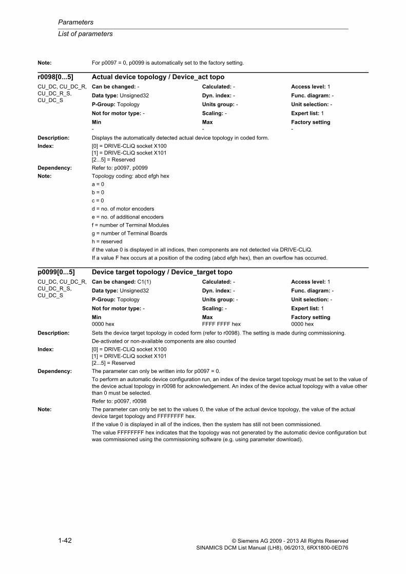
Parameters
List of parameters
1-42 © Siemens AG 2009 - 2013 All Rights ReservedSINAMICS DCM List Manual (LH8), 06/2013, 6RX1800-0ED76
Note: For p0097 = 0, p0099 is automatically set to the factory setting.
Description: Displays the automatically detected actual device topology in coded form.
Index: [0] = DRIVE-CLiQ socket X100[1] = DRIVE-CLiQ socket X101[2...5] = Reserved
Dependency: Refer to: p0097, p0099
Note: Topology coding: abcd efgh hex
a = 0
b = 0
c = 0
d = no. of motor encoders
e = no. of additional encoders
f = number of Terminal Modules
g = number of Terminal Boards
h = reserved
if the value 0 is displayed in all indices, then components are not detected via DRIVE-CLiQ.
If a value F hex occurs at a position of the coding (abcd efgh hex), then an overflow has occurred.
Description: Sets the device target topology in coded form (refer to r0098). The setting is made during commissioning.
De-activated or non-available components are also counted
Index: [0] = DRIVE-CLiQ socket X100[1] = DRIVE-CLiQ socket X101[2...5] = Reserved
Dependency: The parameter can only be written into for p0097 = 0.
To perform an automatic device configuration run, an index of the device target topology must be set to the value of the device actual topology in r0098 for acknowledgement. An index of the device actual topology with a value other than 0 must be selected.
Refer to: p0097, r0098
Note: The parameter can only be set to the values 0, the value of the actual device topology, the value of the actual device target topology and FFFFFFFF hex.
If the value 0 is displayed in all of the indices, then the system has still not been commissioned.
The value FFFFFFFF hex indicates that the topology was not generated by the automatic device configuration but was commissioned using the commissioning software (e.g. using parameter download).
r0098[0...5] Actual device topology / Device_act topoCU_DC, CU_DC_R, CU_DC_R_S, CU_DC_S
Can be changed: - Calculated: - Access level: 1
Data type: Unsigned32 Dyn. index: - Func. diagram: -
P-Group: Topology Units group: - Unit selection: -
Not for motor type: - Scaling: - Expert list: 1
Min Max Factory setting - - -
p0099[0...5] Device target topology / Device_target topoCU_DC, CU_DC_R, CU_DC_R_S, CU_DC_S
Can be changed: C1(1) Calculated: - Access level: 1
Data type: Unsigned32 Dyn. index: - Func. diagram: -
P-Group: Topology Units group: - Unit selection: -
Not for motor type: - Scaling: - Expert list: 1
Min Max Factory setting 0000 hex FFFF FFFF hex 0000 hex

List of parameters
Parameters
1-43© Siemens AG 2009 - 2013 All Rights ReservedSINAMICS DCM List Manual (LH8), 06/2013, 6RX1800-0ED76
Description: The parameter contains the object number via which every drive object can be addressed.
The number of an existing drive object is entered into each index.
Value = 0: No drive object is defined.
Index: [0] = Drive object number Control Unit[1] = Drive object number object 1[2] = Drive object number object 2[3] = Drive object number object 3[4] = Drive object number object 4[5] = Drive object number object 5[6] = Drive object number object 6[7] = Drive object number object 7[8] = Drive object number object 8[9] = Drive object number object 9[10] = Drive object number object 10[11] = Drive object number object 11[12] = Drive object number object 12[13] = Drive object number object 13[14] = Drive object number object 14[15] = Drive object number object 15[16] = Drive object number object 16[17] = Drive object number object 17[18] = Drive object number object 18[19] = Drive object number object 19[20] = Drive object number object 20[21] = Drive object number object 21[22] = Drive object number object 22[23] = Drive object number object 23
Note: The numbers are automatically allocated.
For the commissioning software, this object number cannot be entered using the expert list, but is automatically assigned when inserting an object.
Description: Displays the number of existing or existing and prepared drive objects.
Index: [0] = Existing drive objects[1] = Existing and prepared drive objects
Dependency: Refer to: p0101
Note: The numbers of the drive objects are in p0101.
Index 0:
Displays the number of drive objects that have already been set up.
Index 1:
Displays the number of drive objects that have already been set up and, in addition, the drive objects that still have to be set up.
p0101[0...23] Drive object numbers / DO numbersCU_DC, CU_DC_R, CU_DC_R_S, CU_DC_S
Can be changed: C1(1) Calculated: - Access level: 2
Data type: Unsigned16 Dyn. index: - Func. diagram: -
P-Group: Topology Units group: - Unit selection: -
Not for motor type: - Scaling: - Expert list: 1
Min Max Factory setting 0 62 0
r0102[0...1] Number of drive objects / DO countCU_DC, CU_DC_R, CU_DC_R_S, CU_DC_S
Can be changed: - Calculated: - Access level: 2
Data type: Unsigned16 Dyn. index: - Func. diagram: -
P-Group: Topology Units group: - Unit selection: -
Not for motor type: - Scaling: - Expert list: 1
Min Max Factory setting - - -

Parameters
List of parameters
1-44 © Siemens AG 2009 - 2013 All Rights ReservedSINAMICS DCM List Manual (LH8), 06/2013, 6RX1800-0ED76
Description: The application-specific view of an existing drive object is entered into each index.
The parameter cannot be changed.
Dependency: Refer to: p0107, r0107
Note: The application-specific views are defined in files on the memory card with the following structure:
PDxxxyyy.ACX
xxx: Application-specific view (p0103)
yyy: Type of drive object (p0107)
Example:
PD052017.ACX
--> "017" stands for the drive object of type DC_CTRL
--> "052" is the number of the view for this drive object
Description: Displays the application-specific view of the individual drive object.
Dependency: Refer to: p0107, r0107
Description: Setting to activate/de-activate a drive object.
Value: 0: De-activate drive object1: Activate drive object
Dependency: Refer to: r0106
Notice: The following applies when activating:
If components are inserted for the first time and the appropriate drive object is activated, then the drive system is automatically booted. To do this, the pulses of all of the drive objects must be suppressed.
Description: Setting to activate/de-activate a drive object.
p0103[0...23] Application-specific view / Appl_spec viewCU_DC, CU_DC_R, CU_DC_R_S, CU_DC_S
Can be changed: C1(2) Calculated: - Access level: 2
Data type: Unsigned16 Dyn. index: - Func. diagram: -
P-Group: - Units group: - Unit selection: -
Not for motor type: - Scaling: - Expert list: 1
Min Max Factory setting 0 999 0
r0103 Application-specific view / Appl_spec viewDC_CTRL, DC_CTRL_R, DC_CTRL_R_S, DC_CTRL_S
Can be changed: - Calculated: - Access level: 2
Data type: Unsigned16 Dyn. index: - Func. diagram: -
P-Group: Closed-loop control Units group: - Unit selection: -
Not for motor type: - Scaling: - Expert list: 1
Min Max Factory setting 0 65535 -
p0105 Activate/de-activate drive object / DO act/deactCU_DC, CU_DC_R, CU_DC_R_S, CU_DC_S
Can be changed: U, T Calculated: - Access level: 2
Data type: Integer16 Dyn. index: - Func. diagram: -
P-Group: Closed-loop control Units group: - Unit selection: -
Not for motor type: - Scaling: - Expert list: 1
Min Max Factory setting 0 1 1
p0105 Activate/de-activate drive object / DO act/deactDC_CTRL, DC_CTRL_R, DC_CTRL_R_S, DC_CTRL_S
Can be changed: T Calculated: - Access level: 2
Data type: Integer16 Dyn. index: - Func. diagram: -
P-Group: Closed-loop control Units group: - Unit selection: -
Not for motor type: - Scaling: - Expert list: 1
Min Max Factory setting 0 2 1

List of parameters
Parameters
1-45© Siemens AG 2009 - 2013 All Rights ReservedSINAMICS DCM List Manual (LH8), 06/2013, 6RX1800-0ED76
Value: 0: De-activate drive object1: Activate drive object2: Drive object de-activate and not present
Recommend.: After inserting all of the components of a drive object, before activating, first wait for Alarm A01316.
Dependency: Refer to: r0106
Notice: The following applies when activating:
If components are inserted for the first time and the appropriate drive object is activated, then the drive system is automatically booted. To do this, the pulses of all of the drive objects must be suppressed.
Description: Setting to activate/de-activate a drive object.
Value: 0: De-activate drive object1: Activate drive object2: Drive object de-activate and not present
Recommend.: After inserting all of the components of a drive object, before activating, first wait for Alarm A01316.
Dependency: Refer to: r0106
Caution: When activating drive objects with the safety functions enabled, the following applies:
After reactivating, a warm restart (p0009 = 30, p0976 = 2, 3) or POWER ON should be carried out.
Notice: The following applies when activating:
If components are inserted for the first time and the appropriate drive object is activated, then the drive system is automatically booted. To do this, the pulses of all of the drive objects must be suppressed.
Note: Re value = 0, 2:
When a drive object is deactivated it no longer outputs any errors.
If value = 0:
All components of the drive object were completely commissioned and are deactivated using this value. They can be removed from the DRIVE-CLiQ without any error.
If value = 1:
All components of the drive object must be available for error-free operation.
If value = 2:
Components of a drive object in a project generated offline and set to this value must never be inserted in the actual topology from the very start. This means that the components are marked to be bypassed in the DRIVE-CLiQ line.
For components that comprise several individual components (e.g. Double Motor Modules), it is not permissible to set just one subset to this value.
Description: Setting to activate/de-activate a drive object.
Value: 0: De-activate drive object1: Activate drive object2: Drive object de-activate and not present
Recommend.: After inserting all of the components of a drive object, before activating, first wait for Alarm A01316.
Dependency: Refer to: r0106
p0105 Activate/de-activate drive object / DO act/deactTM150, TM15DI_DO Can be changed: T Calculated: - Access level: 2
Data type: Integer16 Dyn. index: - Func. diagram: -
P-Group: Closed-loop control Units group: - Unit selection: -
Not for motor type: - Scaling: - Expert list: 1
Min Max Factory setting 0 2 1
p0105 Activate/de-activate drive object / DO act/deactTM31 Can be changed: T Calculated: - Access level: 2
Data type: Integer16 Dyn. index: - Func. diagram: -
P-Group: Closed-loop control Units group: - Unit selection: -
Not for motor type: - Scaling: - Expert list: 1
Min Max Factory setting 0 2 1
Parameters
List of parameters
1-46 © Siemens AG 2009 - 2013 All Rights ReservedSINAMICS DCM List Manual (LH8), 06/2013, 6RX1800-0ED76
Warning: A drive that is moved by simulating the inputs of a Terminal Module is brought to a standstill while this parameter is being changed over.
Notice: The following applies when activating:
If components are inserted for the first time and the appropriate drive object is activated, then the drive system is automatically booted. To do this, the pulses of all of the drive objects must be suppressed.
Note: Re value = 0, 2:
When a drive object is deactivated it no longer outputs any errors.
If value = 0:
All components of the drive object were completely commissioned and are deactivated using this value. They can be removed from the DRIVE-CLiQ without any error.
If value = 1:
All components of the drive object must be available for error-free operation.
If value = 2:
Components of a drive object in a project generated offline and set to this value must never be inserted in the actual topology from the very start. This means that the components are marked to be bypassed in the DRIVE-CLiQ line.
For components that comprise several individual components (e.g. Double Motor Modules), it is not permissible to set just one subset to this value.
Description: Displays the "active/inactive" state of a drive object.
Value: 0: Drive object inactive1: Drive object active
Dependency: Refer to: p0105
Description: The type of an existing drive object is entered into each index.
Value: 0: -1: SINAMICS S2: SINAMICS G3: SINAMICS I4: SINAMICS NX/CX326: SINAMICS DC9: SINAMICS S11010: ACTIVE INFEED CONTROL11: SERVO12: VECTOR13: VECTORMV14: VECTORGL15: VECTOR3P16: VECTORSL17: DC_CTRL18: VECTORM2C19: VECTORDM
r0106 Drive object active/inactive / DO act/inactAll objects Can be changed: - Calculated: - Access level: 2
Data type: Integer16 Dyn. index: - Func. diagram: -
P-Group: Closed-loop control Units group: - Unit selection: -
Not for motor type: - Scaling: - Expert list: 1
Min Max Factory setting 0 1 -
p0107[0...23] Drive object type / DO typeCU_DC, CU_DC_R, CU_DC_R_S, CU_DC_S
Can be changed: C1(2) Calculated: - Access level: 2
Data type: Integer16 Dyn. index: - Func. diagram: -
P-Group: - Units group: - Unit selection: -
Not for motor type: - Scaling: - Expert list: 1
Min Max Factory setting 0 600 0

List of parameters
Parameters
1-47© Siemens AG 2009 - 2013 All Rights ReservedSINAMICS DCM List Manual (LH8), 06/2013, 6RX1800-0ED76
20: SMART INFEED CONTROL30: BASIC INFEED CONTROL35: BRAKE MODULE M2C40: ACTIVE INFEED CONTROLMV41: BASIC INFEED CONTROLMV42: ACTIVE INFEED CONTROLM2C51: SINAMICS G120 230 (SingleDO-Drive which combines Device+Vector)52: SINAMICSG120 240_2 (SingleDO-Drive which combines Device+Vector)53: SINAMICS_G120_CU250S_V (SingleDO Drive combines Device+Vector)54: SINAMICSG120 G120D(SingleDO-Drive which combines Device+Vector)55: SINAMICS_G120_CU250S_S (SingleDO Drive combines Device+Servo)56: SINAMICSG110M (SingleDO-Drive which combines Device+Vector)70: HLA100: TB30 (Terminal Board)102: SINAMICS MV150: DRIVE-CLiQ Hub Module200: TM31 (Terminal Module)201: TM41 (Terminal Module)202: TM17 High Feature (Terminal Module)203: TM15 (Terminal Module)204: TM15 (Terminal Module for SINAMICS)205: TM54F - Master (Terminal Module)206: TM54F - Slave (Terminal Module)207: TM120 (Terminal Module)208: TM150 (Terminal Module)254: CU-LINK300: ENCODER600: SINAMICS V60-G2 V80-G2
Index: [0] = Drive object type Control Unit[1] = Drive object type object 1[2] = Drive object type object 2[3] = Drive object type object 3[4] = Drive object type object 4[5] = Drive object type object 5[6] = Drive object type object 6[7] = Drive object type object 7[8] = Drive object type object 8[9] = Drive object type object 9[10] = Drive object type object 10[11] = Drive object type object 11[12] = Drive object type object 12[13] = Drive object type object 13[14] = Drive object type object 14[15] = Drive object type object 15[16] = Drive object type object 16[17] = Drive object type object 17[18] = Drive object type object 18[19] = Drive object type object 19[20] = Drive object type object 20[21] = Drive object type object 21[22] = Drive object type object 22[23] = Drive object type object 23
Dependency: Refer to: p0103, r0103
Caution: If you change this parameter and exit the device commissioning mode, then the complete software will be set up again and all of the previous drive parameter settings are deleted.
Note: The number (p0101) and the associated drive object type are in the same index.

Parameters
List of parameters
1-48 © Siemens AG 2009 - 2013 All Rights ReservedSINAMICS DCM List Manual (LH8), 06/2013, 6RX1800-0ED76
Description: Displays the type of each drive object.
Value: 0: -1: SINAMICS S2: SINAMICS G3: SINAMICS I4: SINAMICS NX/CX326: SINAMICS DC9: SINAMICS S11010: ACTIVE INFEED CONTROL11: SERVO12: VECTOR13: VECTORMV14: VECTORGL15: VECTOR3P16: VECTORSL17: DC_CTRL18: VECTORM2C19: VECTORDM20: SMART INFEED CONTROL30: BASIC INFEED CONTROL35: BRAKE MODULE M2C40: ACTIVE INFEED CONTROLMV41: BASIC INFEED CONTROLMV42: ACTIVE INFEED CONTROLM2C51: SINAMICS G120 230 (SingleDO-Drive which combines Device+Vector)52: SINAMICSG120 240_2 (SingleDO-Drive which combines Device+Vector)53: SINAMICS_G120_CU250S_V (SingleDO Drive combines Device+Vector)54: SINAMICSG120 G120D(SingleDO-Drive which combines Device+Vector)55: SINAMICS_G120_CU250S_S (SingleDO Drive combines Device+Servo)56: SINAMICSG110M (SingleDO-Drive which combines Device+Vector)70: HLA100: TB30 (Terminal Board)102: SINAMICS MV150: DRIVE-CLiQ Hub Module200: TM31 (Terminal Module)201: TM41 (Terminal Module)202: TM17 High Feature (Terminal Module)203: TM15 (Terminal Module)204: TM15 (Terminal Module for SINAMICS)205: TM54F - Master (Terminal Module)206: TM54F - Slave (Terminal Module)207: TM120 (Terminal Module)208: TM150 (Terminal Module)254: CU-LINK300: ENCODER600: SINAMICS V60-G2 V80-G2
Dependency: Refer to: p0103, r0103
r0107 Drive object type / DO typeDC_CTRL, DC_CTRL_R, DC_CTRL_R_S, DC_CTRL_S, TM150, TM15DI_DO, TM31
Can be changed: - Calculated: - Access level: 2
Data type: Integer16 Dyn. index: - Func. diagram: -
P-Group: Closed-loop control Units group: - Unit selection: -
Not for motor type: - Scaling: - Expert list: 1
Min Max Factory setting 0 600 -
List of parameters
Parameters
1-49© Siemens AG 2009 - 2013 All Rights ReservedSINAMICS DCM List Manual (LH8), 06/2013, 6RX1800-0ED76
Description: The function module of an existing drive object is entered into each index (also refer to p0101, p0107).
The following bits are available for the Control Unit (Index 0):
Bit 18: Free function blocks
Bit 31: PROFINET
For all other drive objects (Index > 0), the significance of the bits should be taken from the display parameters r0108 of the drive object.
Index: [0] = Function module Control Unit[1] = Function module object 1[2] = Function module object 2[3] = Function module object 3[4] = Function module object 4[5] = Function module object 5[6] = Function module object 6[7] = Function module object 7[8] = Function module object 8[9] = Function module object 9[10] = Function module object 10[11] = Function module object 11[12] = Function module object 12[13] = Function module object 13[14] = Function module object 14[15] = Function module object 15[16] = Function module object 16[17] = Function module object 17[18] = Function module object 18[19] = Function module object 19[20] = Function module object 20[21] = Function module object 21[22] = Function module object 22[23] = Function module object 23
Note: A "function module" is a functional expansion of a drive object that can be activated when commissioning.
Description: Displays the activated function module for the particular drive object.
Note: A "function module" is a functional expansion of a drive object that can be activated when commissioning.
p0108[0...23] Drive objects function module / DO function moduleCU_DC, CU_DC_R, CU_DC_R_S, CU_DC_S
Can be changed: C1(2) Calculated: - Access level: 2
Data type: Unsigned32 Dyn. index: - Func. diagram: -
P-Group: - Units group: - Unit selection: -
Not for motor type: - Scaling: - Expert list: 1
Min Max Factory setting - - 0000 0000 0000 0000 0000
0000 0000 0000 bin
Bit field: Bit Signal name 1 signal 0 signal FP18 Bit 18 ON OFF -31 Bit 31 ON OFF -
r0108 Drive objects function module / DO function moduleDC_CTRL, DC_CTRL_R, DC_CTRL_R_S, DC_CTRL_S
Can be changed: - Calculated: - Access level: 2
Data type: Unsigned32 Dyn. index: - Func. diagram: -
P-Group: Closed-loop control Units group: - Unit selection: -
Not for motor type: - Scaling: - Expert list: 1
Min Max Factory setting - - -
Bit field: Bit Signal name 1 signal 0 signal FP16 Technology controller / Tech_ctrl Activated Not activated -18 Free function blocks / FBLOCKS Activated Not activated -31 PROFINET / PROFINET Activated Not activated -

Parameters
List of parameters
1-50 © Siemens AG 2009 - 2013 All Rights ReservedSINAMICS DCM List Manual (LH8), 06/2013, 6RX1800-0ED76
Description: Displays the activated function module for the particular drive object.
Note: A "function module" is a functional expansion of a drive object that can be activated when commissioning.
Description: Displays the basic sampling times.
The sampling times are set using p0112 and p0115. The values for the basic sampling times are determined as a result of these settings.
Index: [0] = Basic sampling time 0[1] = Basic sampling time 1[2] = Basic sampling time 2
Description: Displays the selected basic sampling time for this drive object.
Dependency: Refer to: r0110
Description: Displays the selected basic sampling time for this drive object.
Dependency: Refer to: r0110
Note: For TB30 and the Terminal Module, this parameter has no significance.
For TB30 and certain Terminal Modules, the sampling times can be set using p4099 (see description of p4099 for the Module in question).
r0108 Drive objects function module / DO function moduleTM150, TM15DI_DO, TM31
Can be changed: - Calculated: - Access level: 2
Data type: Unsigned32 Dyn. index: - Func. diagram: -
P-Group: Closed-loop control Units group: - Unit selection: -
Not for motor type: - Scaling: - Expert list: 1
Min Max Factory setting - - -
Bit field: Bit Signal name 1 signal 0 signal FP18 Free function blocks / FBLOCKS Activated Not activated -31 PROFINET / PROFINET Activated Not activated -
r0110[0...2] Basic sampling times / t_basisCU_DC, CU_DC_R, CU_DC_R_S, CU_DC_S
Can be changed: - Calculated: - Access level: 3
Data type: FloatingPoint32 Dyn. index: - Func. diagram: -
P-Group: Closed-loop control Units group: - Unit selection: -
Not for motor type: - Scaling: - Expert list: 1
Min Max Factory setting 0.00 [µs] 10000.00 [µs] - [µs]
r0111 Basic sampling time selection / t_basis selCU_DC, CU_DC_R, CU_DC_R_S, CU_DC_S, DC_CTRL, DC_CTRL_R, DC_CTRL_R_S, DC_CTRL_S
Can be changed: - Calculated: - Access level: 3
Data type: Integer16 Dyn. index: - Func. diagram: -
P-Group: Closed-loop control Units group: - Unit selection: -
Not for motor type: - Scaling: - Expert list: 1
Min Max Factory setting 0 2 -
r0111 Basic sampling time selection / t_basis selTM15DI_DO, TM31 Can be changed: - Calculated: - Access level: 3
Data type: Integer16 Dyn. index: - Func. diagram: -
P-Group: Closed-loop control Units group: - Unit selection: -
Not for motor type: - Scaling: - Expert list: 1
Min Max Factory setting 0 2 -
List of parameters
Parameters
1-51© Siemens AG 2009 - 2013 All Rights ReservedSINAMICS DCM List Manual (LH8), 06/2013, 6RX1800-0ED76
Description: Pre-assignment of the sampling times in p0115.
The clock cycles for the current controller / speed controller / - / setpoint channel / - / - / technology controller are defined as follows:
p0112 = 3: 1000 / 2000 / - / 4000 / - / - / 4000 µs
Value: 0: Expert3: Standard
Note: For p0112 = 0 (expert) the individual sampling times in p0115 can be adjusted.
Description: Sets the basic sampling time for supplementary functions (DCC, free function blocks) on this object.
Only setting values that are an integer multiple of 125 µs are permissible.
Index: [0] = Basic sampl. time
Description: Sets the sampling times for the control loops.
The default setting is made using p0112 and can only be individually changed for p0112 = 0 (expert).
Index: [0] = Current controller[1] = Speed controller[2] = -[3] = Setpoint channel[4] = -[5] = -[6] = Technology controller
Dependency: The sampling times can only be separately set if p0112 is 0 (expert). If a sampling time is modified in the expert mode, then all of the sampling times with higher indices are automatically changed in the same ratio as the sam-pling time itself was changed. Slower time slices are only taken if the calculated sampling time is also permitted. Upper limit is 8 ms.
p0112 Sampling times pre-setting p0115 / t_sample for p0115DC_CTRL, DC_CTRL_R, DC_CTRL_R_S, DC_CTRL_S
Can be changed: C1(3) Calculated: - Access level: 3
Data type: Integer16 Dyn. index: - Func. diagram: -
P-Group: Closed-loop control Units group: - Unit selection: -
Not for motor type: - Scaling: - Expert list: 1
Min Max Factory setting 0 3 3
p0115[0] Sampling time for supplementary functions / t_samp suppl_fctCU_DC, CU_DC_R, CU_DC_R_S, CU_DC_S
Can be changed: C1(3) Calculated: - Access level: 3
Data type: FloatingPoint32 Dyn. index: - Func. diagram: -
P-Group: Closed-loop control Units group: - Unit selection: -
Not for motor type: - Scaling: - Expert list: 1
Min Max Factory setting 0.00 [µs] 16000.00 [µs] 4000.00 [µs]
p0115[0...6] Sampling times for internal control loops / t_sample int ctrlDC_CTRL, DC_CTRL_R, DC_CTRL_R_S, DC_CTRL_S
Can be changed: C1(3) Calculated: - Access level: 3
Data type: FloatingPoint32 Dyn. index: - Func. diagram: -
P-Group: Closed-loop control Units group: - Unit selection: -
Not for motor type: - Scaling: - Expert list: 1
Min Max Factory setting 1000.00 [µs] 16000.00 [µs] [0] 1000.00 [µs]
[1] 2000.00 [µs]
[2] 8000.00 [µs]
[3] 4000.00 [µs]
[4] 8000.00 [µs]
[5] 8000.00 [µs]
[6] 8000.00 [µs]

Parameters
List of parameters
1-52 © Siemens AG 2009 - 2013 All Rights ReservedSINAMICS DCM List Manual (LH8), 06/2013, 6RX1800-0ED76
Higher-level controls must be calculated in integral ratios to lower-level controls (e.g. p0115[1] = N * p0115[0]; where N is an integer number). The sampling time of the speed controller (p0115[1]) can have as a maximum a value of 800% of the current controller sampling time (p0115[0]).
Refer to: r0110, r0111, p0112
Note: For function modules that can be activated (e.g. technology controller), the parameters values are pre-assigned.
The current controller sampling time (p0115[0]) is permanently set to 1 ms and cannot be changed.
Description: Sets the sampling times for supplementary functions (DCC, free function blocks) on this object.
Only setting values that are an integer multiple of 125 µs are permissible.
Index: [0] = Basic sampl. time
Note: This parameter only applies to set the sampling times of possible supplementary functions.
The sampling times for inputs/outputs must be set in p4099.
Description: Displays the recommended sampling time for the drive objects.
r00116[0] = recommended sampling time:
Recommended value which would then make the complete system operational.
r00116[1] = recommended sampling time:
Recommended value, which after changing other clock cycles on the DRIVE-CLiQ line, would result in an opera-tional system.
Index: [0] = Change only for the actual drive object[1] = Changing all objects on the DRIVE-CLiQ line
Dependency: Refer to: p0115
Description: The power unit data set is assigned to a power unit using this parameter.
This unique component number is assigned when parameterizing the topology.
Only component numbers can be entered into this parameter that correspond to a power unit.
Dependency: Refer to: p0107, r0107
p0115[0] Sampling time for supplementary functions / t_samp suppl_fctTM150, TM15DI_DO, TM31
Can be changed: C1(3) Calculated: - Access level: 3
Data type: FloatingPoint32 Dyn. index: - Func. diagram: -
P-Group: Closed-loop control Units group: - Unit selection: -
Not for motor type: - Scaling: - Expert list: 1
Min Max Factory setting 0.00 [µs] 16000.00 [µs] 4000.00 [µs]
r0116[0...1] Drive object clock cycle recommended / DO_clock recomCU_DC, CU_DC_R, CU_DC_R_S, CU_DC_S, DC_CTRL, DC_CTRL_R, DC_CTRL_R_S, DC_CTRL_S, TM15DI_DO, TM31
Can be changed: - Calculated: - Access level: 3
Data type: FloatingPoint32 Dyn. index: - Func. diagram: -
P-Group: Closed-loop control Units group: - Unit selection: -
Not for motor type: - Scaling: - Expert list: 1
Min Max Factory setting - [µs] - [µs] - [µs]
p0121[0...n] Power unit component number / PU comp_noDC_CTRL, DC_CTRL_R, DC_CTRL_R_S, DC_CTRL_S
Can be changed: C1(4) Calculated: - Access level: 3
Data type: Unsigned8 Dyn. index: PDS Func. diagram: -
P-Group: Data sets Units group: - Unit selection: -
Not for motor type: - Scaling: - Expert list: 1
Min Max Factory setting 0 199 0

List of parameters
Parameters
1-53© Siemens AG 2009 - 2013 All Rights ReservedSINAMICS DCM List Manual (LH8), 06/2013, 6RX1800-0ED76
Description: Detection of the main components of the drive object selected via the index.
Description: Setting to activate/de-activate a power unit component.
Value: 0: De-activate component1: Activate component2: Component de-activate and not present
Recommend.: After inserting a component, before activating, first wait for Alarm A01317.
Caution: For a parallel connection, the following applies:
When deactivating individual power units using p0125, it is not permissible that the power units of the parallel con-nection involved are connected. Infeed units should be disconnected from the line supply (for example, using a con-tactor). Motor feeder cables should be disconnected. In addition, defective power units should be disconnected from the DC link.
Caution: It is not permissible to de-activate drive objects with safety functions enabled.
Note: The activation of a component can be rejected if the component was inserted for the first time. In this case, it is only possible to activate the component when the pulses for all of the drive objects are inhibited.
For units connected in parallel, when one of the power units is de-activated, then the enable in p7001 is withdrawn.
Re value = 0, 2:
When a component is deactivated it no longer outputs any errors.
If value = 0:
The component was completely commissioned and is deactivated using this value. It can be removed from the DRIVE-CLiQ without any error.
If value = 1:
The component must be available for error-free operation.
If value = 2:
A component in a project generated offline and set to this value must never be inserted in the actual topology from the very start. This means that the component is marked to be bypassed in the DRIVE-CLiQ line.
For components that comprise several individual components (e.g. Double Motor Modules), it is not permissible to set just one subset to this value.
Description: Sets the number of Encoder Data Sets (EDS).
Note: When parameterizing the drive with "no encoder" there must be at least one encoder data set (p0140 >= 1).
p0124[0...23] Main component detection using LED / M_comp detect LEDCU_DC, CU_DC_R, CU_DC_R_S, CU_DC_S
Can be changed: U, T Calculated: - Access level: 3
Data type: Unsigned8 Dyn. index: - Func. diagram: -
P-Group: Converter Units group: - Unit selection: -
Not for motor type: - Scaling: - Expert list: 1
Min Max Factory setting 0 1 0
p0125[0...n] Activate/de-activate power unit components / PU_comp act/deactDC_CTRL, DC_CTRL_R, DC_CTRL_R_S, DC_CTRL_S
Can be changed: C1(4), T Calculated: - Access level: 4
Data type: Integer16 Dyn. index: PDS Func. diagram: -
P-Group: Data sets Units group: - Unit selection: -
Not for motor type: - Scaling: - Expert list: 1
Min Max Factory setting 0 2 1
p0140 Number of Encoder Data Sets (EDS) / EDS countDC_CTRL, DC_CTRL_R, DC_CTRL_R_S, DC_CTRL_S
Can be changed: C1(3) Calculated: - Access level: 2
Data type: Unsigned8 Dyn. index: - Func. diagram: -
P-Group: Data sets Units group: - Unit selection: -
Not for motor type: - Scaling: - Expert list: 1
Min Max Factory setting 1 16 1

Parameters
List of parameters
1-54 © Siemens AG 2009 - 2013 All Rights ReservedSINAMICS DCM List Manual (LH8), 06/2013, 6RX1800-0ED76
Description: This parameter is used to assign the encoder data set to an encoder evaluation (e.g. SMC).
This unique component number is assigned when parameterizing the topology.
Only component numbers can be entered into this parameter that correspond to an encoder evaluation.
Note: If the encoder evaluation and encoder are integrated (motor with DRIVE-CLiQ), then their component numbers are identical.
For an SMC, different component numbers are assigned for the SMC (p0141) and the (actual) encoder (p0142).
Description: This parameter is used to assign the encoder data set to an encoder.
This assignment is made using the unique component number that was assigned when parameterizing the topol-ogy.
Only component numbers can be entered into this parameter that correspond to an encoder.
Note: If the encoder evaluation and encoder are integrated (motor with DRIVE-CLiQ), then their component numbers are identical.
For an SMC, different component numbers are assigned for the SMC (p0141) and the (actual) encoder (p0142).
Description: Detects the Sensor Module assigned to this drive and data set.
Note: While p0144 = 1, the READY LED flashes green/orange or red/orange with 2 Hz at the appropriate Sensor Module.
Description: Setting to activate/de-activate an encoder interface (Sensor Module).
Value: 0: De-activate component1: Activate component2: Component de-activate and not present
Recommend.: After inserting a component, before activating, first wait for Alarm A01317.
Dependency: Refer to: r0146
p0141[0...n] Encoder interface (Sensor Module) component number / Enc_interf comp_noDC_CTRL, DC_CTRL_R, DC_CTRL_R_S, DC_CTRL_S
Can be changed: C1(4) Calculated: - Access level: 3
Data type: Unsigned8 Dyn. index: EDS, p0140 Func. diagram: 4704, 8570
P-Group: Data sets Units group: - Unit selection: -
Not for motor type: - Scaling: - Expert list: 1
Min Max Factory setting 0 199 0
p0142[0...n] Encoder component number / Encoder comp_noDC_CTRL, DC_CTRL_R, DC_CTRL_R_S, DC_CTRL_S
Can be changed: C1(4) Calculated: - Access level: 3
Data type: Unsigned8 Dyn. index: EDS, p0140 Func. diagram: 4704
P-Group: Data sets Units group: - Unit selection: -
Not for motor type: - Scaling: - Expert list: 1
Min Max Factory setting 0 199 0
p0144[0...n] Sensor Module detection via LED / SM detection LEDDC_CTRL, DC_CTRL_R, DC_CTRL_R_S, DC_CTRL_S
Can be changed: U, T Calculated: - Access level: 2
Data type: Unsigned8 Dyn. index: EDS, p0140 Func. diagram: -
P-Group: Encoder Units group: - Unit selection: -
Not for motor type: - Scaling: - Expert list: 1
Min Max Factory setting 0 1 0
p0145[0...n] Activate/de-activate encoder interface / Enc_intf act/deactDC_CTRL, DC_CTRL_R, DC_CTRL_R_S, DC_CTRL_S
Can be changed: C1(4), U, T Calculated: - Access level: 2
Data type: Integer16 Dyn. index: EDS, p0140 Func. diagram: -
P-Group: Data sets Units group: - Unit selection: -
Not for motor type: - Scaling: - Expert list: 1
Min Max Factory setting 0 2 1

List of parameters
Parameters
1-55© Siemens AG 2009 - 2013 All Rights ReservedSINAMICS DCM List Manual (LH8), 06/2013, 6RX1800-0ED76
Note: The de-activation of an encoder interface corresponds to the"parking encoder" function and has the same effect.
The activation of a component can be rejected if the component was inserted for the first time.
In this case, it is only possible to activate the component when the pulses for all of the drive objects are inhibited.
With the encoder interface for encoder 1 (motor encoder), the relevant drive object for writing the parameter must be in the "Ready for operation" state.
With the encoder interface for encoders 2 and 3, the parameter can also be written during operation.
Re value = 0, 2:
When a component is deactivated it no longer outputs any errors.
If value = 0:
The component was completely commissioned and is deactivated using this value. It can be removed from the DRIVE-CLiQ without any error.
If value = 1:
The component must be available for error-free operation.
If value = 2:
A component in a project generated offline and set to this value must never be inserted in the actual topology from the very start.
For components that comprise several individual components (e.g. Double Motor Modules), it is not permissible to set just one subset to this value.
Description: Displays the "active" or "inactive" state of an encoder interface (Sensor Module).
Value: 0: Component inactive1: Component active
Dependency: Refer to: p0105, p0145, p0480
Description: Displays the version of the EEPROM data of the Sensor Module.
Dependency: Refer to: r0157
Note: Example:
The value 1010100 should be interpreted as V01.01.01.00.
Description: Displays the firmware version of the Sensor Module.
Dependency: Refer to: r0018, r0158, r0197, r0198
r0146[0...n] Encoder interface active/inactive / Enc_intf act/inactDC_CTRL, DC_CTRL_R, DC_CTRL_R_S, DC_CTRL_S
Can be changed: - Calculated: - Access level: 2
Data type: Integer16 Dyn. index: EDS, p0140 Func. diagram: -
P-Group: Data sets Units group: - Unit selection: -
Not for motor type: - Scaling: - Expert list: 1
Min Max Factory setting 0 1 -
r0147[0...n] Sensor Module EEPROM data version / SM EEPROM versionDC_CTRL, DC_CTRL_R, DC_CTRL_R_S, DC_CTRL_S
Can be changed: - Calculated: - Access level: 3
Data type: Unsigned32 Dyn. index: EDS, p0140 Func. diagram: -
P-Group: Encoder Units group: - Unit selection: -
Not for motor type: - Scaling: - Expert list: 1
Min Max Factory setting - - -
r0148[0...n] Sensor Module firmware version / SM FW versionDC_CTRL, DC_CTRL_R, DC_CTRL_R_S, DC_CTRL_S
Can be changed: - Calculated: - Access level: 3
Data type: Unsigned32 Dyn. index: EDS, p0140 Func. diagram: -
P-Group: Encoder Units group: - Unit selection: -
Not for motor type: - Scaling: - Expert list: 1
Min Max Factory setting - - -

Parameters
List of parameters
1-56 © Siemens AG 2009 - 2013 All Rights ReservedSINAMICS DCM List Manual (LH8), 06/2013, 6RX1800-0ED76
Note: Example:
The value 1010100 should be interpreted as V01.01.01.00.
Description: Sets the component number for the Terminal Module.
This unique component number is assigned when parameterizing the topology.
Only component numbers can be entered into this parameter that correspond to a Terminal Module.
Description: Detects the Terminal Module assigned to this drive and data set.
Note: While p0154 = 1, the READY LED flashes green/orange or red/orange with 2 Hz at the appropriate Terminal Mod-ule.
Description: Displays the version of the EPROM data of the Terminal Module.
Dependency: Refer to: r0147
Note: Example:
The value 1010100 should be interpreted as V01.01.01.00.
Description: Displays the firmware version of the Terminal Module.
Dependency: Refer to: r0018, r0148, r0197, r0198
Note: Example:
The value 1010100 should be interpreted as V01.01.01.00.
p0151 Terminal Module component number / TM comp_noTM150, TM15DI_DO, TM31
Can be changed: C1(4) Calculated: - Access level: 3
Data type: Unsigned8 Dyn. index: - Func. diagram: -
P-Group: Data sets Units group: - Unit selection: -
Not for motor type: - Scaling: - Expert list: 1
Min Max Factory setting 0 199 0
p0154 Terminal Module detection via LED / TM detection LEDTM150, TM15DI_DO, TM31
Can be changed: U, T Calculated: - Access level: 2
Data type: Unsigned8 Dyn. index: - Func. diagram: -
P-Group: Terminals Units group: - Unit selection: -
Not for motor type: - Scaling: - Expert list: 1
Min Max Factory setting 0 1 0
r0157 Terminal Module EPROM data version / TM EPROM versionTM150, TM15DI_DO, TM31
Can be changed: - Calculated: - Access level: 3
Data type: Unsigned32 Dyn. index: - Func. diagram: -
P-Group: Terminals Units group: - Unit selection: -
Not for motor type: - Scaling: - Expert list: 1
Min Max Factory setting - - -
r0158 Terminal Module firmware version / TM FW versionTM150, TM15DI_DO, TM31
Can be changed: - Calculated: - Access level: 3
Data type: Unsigned32 Dyn. index: - Func. diagram: -
P-Group: Terminals Units group: - Unit selection: -
Not for motor type: - Scaling: - Expert list: 1
Min Max Factory setting - - -
List of parameters
Parameters
1-57© Siemens AG 2009 - 2013 All Rights ReservedSINAMICS DCM List Manual (LH8), 06/2013, 6RX1800-0ED76
Description: Sets the number of Command Data Sets (CDS).
Note: It is possible to toggle between command parameters (BICO parameters) using this data set changeover.
Description: Sets the number of Drive Data Sets (DDS).
Description: Assign a drive data set (= index) the corresponding encoder data set (EDS) for encoder 1.
The value corresponds to the number of the assigned encoder data set.
Example:
Encoder data set 0 should be assigned to encoder 1 in drive data set 2.
--> p0187[2] = 0
Note: A value of 99 means that no encoder has been assigned to this drive data set (not configured).
Description: Assign a drive data set (= index) the corresponding encoder data set (EDS) for encoder 2.
The value corresponds to the number of the assigned encoder data set.
Example:
Encoder data set 1 should be assigned to encoder 2 in drive data set 2.
--> p0188[2] = 1
Note: A value of 99 means that no encoder has been assigned to this drive data set (not configured).
p0170 Number of Command Data Sets (CDS) / CDS countDC_CTRL, DC_CTRL_R, DC_CTRL_R_S, DC_CTRL_S
Can be changed: C1(3) Calculated: - Access level: 2
Data type: Unsigned8 Dyn. index: - Func. diagram: -
P-Group: Commands Units group: - Unit selection: -
Not for motor type: - Scaling: - Expert list: 1
Min Max Factory setting 2 2 2
p0180 Number of Drive Data Sets (DDS) / DDS countDC_CTRL, DC_CTRL_R, DC_CTRL_R_S, DC_CTRL_S
Can be changed: C1(3) Calculated: - Access level: 2
Data type: Unsigned8 Dyn. index: - Func. diagram: 8565
P-Group: Data sets Units group: - Unit selection: -
Not for motor type: - Scaling: - Expert list: 1
Min Max Factory setting 4 4 4
p0187[0...n] Encoder 1 encoder data set number / Enc 1 EDS numberDC_CTRL, DC_CTRL_R, DC_CTRL_R_S, DC_CTRL_S
Can be changed: C1(4) Calculated: - Access level: 3
Data type: Unsigned8 Dyn. index: DDS, p0180 Func. diagram: 8570
P-Group: Data sets Units group: - Unit selection: -
Not for motor type: - Scaling: - Expert list: 1
Min Max Factory setting 0 99 99
p0188[0...n] Encoder 2 encoder data set number / Enc 2 EDS numberDC_CTRL, DC_CTRL_R
Can be changed: C1(4) Calculated: - Access level: 3
Data type: Unsigned8 Dyn. index: DDS, p0180 Func. diagram: 8570
P-Group: Data sets Units group: - Unit selection: -
Not for motor type: - Scaling: - Expert list: 1
Min Max Factory setting 0 99 99

Parameters
List of parameters
1-58 © Siemens AG 2009 - 2013 All Rights ReservedSINAMICS DCM List Manual (LH8), 06/2013, 6RX1800-0ED76
Description: Displays the status of DRIVE-CLiQ components.
r0196[0...1]: Not used
r0196[2]: Status of DRIVE-CLiQ component with component number 2
...
r0196[255]: Status of DRIVE-CLiQ component with component number 255
Note: Structure of status value: Bits 31 ... 08, 07, 06 ... 04, 03 ... 00
Re Bit 31 ... 08: Reserved
Re Bit 07: 1: Part of target topology, 0: Only in actual topology
Re Bit 06 ... 04: 1: Active, 0: Inactive or parked
Re bit 03 ... 00:
0: Component data not available.
1: Power-up, acyclic DRIVE-CLiQ communication (LED = orange).
2: Ready for operation, cyclic DRIVE-CLiQ communication (LED = green).
3: Alarm (LED = green).
4: Fault (LED = red).
5: Detection via LED and ready for operation (LED = green/orange).
6: Detection via LED and alarm (LED = green/orange).
7: Detection via LED and fault (LED = red/orange).
8: Downloading firmware (LED = green/red at 0.5 Hz).
9: Firmware downloading completed, Waiting for POWER ON (LED = green/red at 2.0 Hz).
Description: Displays the bootloader version.
Index 0:
Displays the bootloader version.
Index 1:
Displays the bootloader version 3 (for CU320-2 and CU310-2)
Value 0 means that boot loader 3 is not available.
Dependency: Refer to: r0018, r0148, r0158, r0198
Note: Example:
The value 1010100 should be interpreted as V01.01.01.00.
r0196[0...255] DRIVE-CLiQ component status / DQ comp statusCU_DC, CU_DC_R, CU_DC_R_S, CU_DC_S
Can be changed: - Calculated: - Access level: 3
Data type: Unsigned32 Dyn. index: - Func. diagram: -
P-Group: - Units group: - Unit selection: -
Not for motor type: - Scaling: - Expert list: 1
Min Max Factory setting - - -
r0197[0...1] Bootloader version / Bootloader versCU_DC, CU_DC_R, CU_DC_R_S, CU_DC_S
Can be changed: - Calculated: - Access level: 4
Data type: Unsigned32 Dyn. index: - Func. diagram: -
P-Group: Closed-loop control Units group: - Unit selection: -
Not for motor type: - Scaling: - Expert list: 1
Min Max Factory setting - - -

List of parameters
Parameters
1-59© Siemens AG 2009 - 2013 All Rights ReservedSINAMICS DCM List Manual (LH8), 06/2013, 6RX1800-0ED76
Description: Displays the BIOS and EEPROM data version.
r0198[0]: BIOS version
r0198[1]: EEPROM data version
Dependency: Refer to: r0018, r0148, r0158, r0197
Note: Example:
The value 1010100 should be interpreted as V01.01.01.00.
Description: Freely assignable name for a drive object.
In the commissioning software, this name cannot be entered using the expert list, but is specified in the configura-tion assistant. The object name can be subsequently modified in the Project Navigator using standard Windows resources.
Note: The parameter is not influenced by setting the factory setting.
Description: Displays the unique code number of the power unit.
Note: r0200 = 0: No power unit found
Description: Code number of the power unit.
Each time the system boots, the code number is transferred from the data of the power unit to r0200 and to p0201.
r0198[0...1] BIOS/EEPROM data version / BIOS/EEPROM versCU_DC, CU_DC_R, CU_DC_R_S, CU_DC_S
Can be changed: - Calculated: - Access level: 4
Data type: Unsigned32 Dyn. index: - Func. diagram: -
P-Group: Closed-loop control Units group: - Unit selection: -
Not for motor type: - Scaling: - Expert list: 1
Min Max Factory setting - - -
p0199[0...24] Drive object name / DO nameAll objects Can be changed: C1 Calculated: - Access level: 2
Data type: Unsigned16 Dyn. index: - Func. diagram: -
P-Group: - Units group: - Unit selection: -
Not for motor type: - Scaling: - Expert list: 1
Min Max Factory setting 0 65535 0
r0200[0...n] Power unit code number actual / PU code no. actDC_CTRL, DC_CTRL_R, DC_CTRL_R_S, DC_CTRL_S
Can be changed: - Calculated: - Access level: 3
Data type: Unsigned16 Dyn. index: PDS Func. diagram: -
P-Group: Converter Units group: - Unit selection: -
Not for motor type: - Scaling: - Expert list: 1
Min Max Factory setting - - -
p0201[0...n] Power unit code number / PU code noDC_CTRL, DC_CTRL_R, DC_CTRL_R_S, DC_CTRL_S
Can be changed: C2 Calculated: - Access level: 4
Data type: Unsigned16 Dyn. index: PDS Func. diagram: -
P-Group: - Units group: - Unit selection: -
Not for motor type: - Scaling: - Expert list: 1
Min Max Factory setting 0 65535 0

Parameters
List of parameters
1-60 © Siemens AG 2009 - 2013 All Rights ReservedSINAMICS DCM List Manual (LH8), 06/2013, 6RX1800-0ED76
Description: Displays the name of the firmware package on the memory card/device memory.
r0203[0]: Name character 1
...
r0203[15]: Name character 16
For the commissioning software, the ASCII characters are displayed uncoded.
Notice: An ASCII table (excerpt) can be found, for example, in the appendix to the List Manual.
Description: Setting to automatically calculate motor parameters and closed-loop control parameters from rating plate data.
Value: 0: No calculation1: Complete calculation
Notice: After the value has been modified, no further parameter modifications can be made and the status is shown in r3996. Modifications can be made again when r3996 = 0.
Description: Selects the encoder from the list of encoder types supported.
Value: 0: No encoder3001: 1024 HTL A/B R3002: 1024 TTL A/B R3003: 2048 HTL A/B R3005: 1024 HTL A/B3006: 1024 TTL A/B3007: 2048 HTL A/B3008: 2048 TTL A/B3009: 1024 HTL A/B unipolar3011: 2048 HTL A/B unipolar3020: 2048 TTL A/B R, with sense3081: SSI, Singleturn, 24 V3082: SSI, Multiturn 4096, 24 V3090: 4096, HTL, A/B, SSI, Singleturn9999: User-defined20000: Encoder from OEM encoder list
Caution: An encoder type with p0400 < 9999 defines an encoder for which there is an encoder parameter list. When select-ing a catalog encoder (p0400 < 9999) the parameters from the encoder parameter list cannot be changed (write protection). To remove write protection, the encoder type should be set to a third-party encoder (p0400 = 9999).
r0203[0...15] Firmware package name / FW pkg nameCU_DC, CU_DC_R, CU_DC_R_S, CU_DC_S
Can be changed: - Calculated: - Access level: 4
Data type: Unsigned8 Dyn. index: - Func. diagram: -
P-Group: - Units group: - Unit selection: -
Not for motor type: - Scaling: - Expert list: 1
Min Max Factory setting - - -
p0340[0...n] Automatic calculation motor/control parameters / Calc auto parDC_CTRL, DC_CTRL_R, DC_CTRL_R_S, DC_CTRL_S
Can be changed: C2(3), T Calculated: - Access level: 3
Data type: Integer16 Dyn. index: DDS, p0180 Func. diagram: -
P-Group: Motor Units group: - Unit selection: -
Not for motor type: - Scaling: - Expert list: 1
Min Max Factory setting 0 1 0
p0400[0...n] Encoder type selection / Enc_typ selDC_CTRL, DC_CTRL_R, DC_CTRL_R_S, DC_CTRL_S
Can be changed: C2(1, 4) Calculated: - Access level: 1
Data type: Integer16 Dyn. index: EDS, p0140 Func. diagram: 1580, 4704
P-Group: Encoder Units group: - Unit selection: -
Not for motor type: - Scaling: - Expert list: 1
Min Max Factory setting 0 20000 0
List of parameters
Parameters
1-61© Siemens AG 2009 - 2013 All Rights ReservedSINAMICS DCM List Manual (LH8), 06/2013, 6RX1800-0ED76
Note: The connected encoder can be identified by p0400 = 10000. This assumes that the encoder supports this method, which is possible in the following cases: Motor with DRIVE-CLiQ, encoder with EnDat interface, DRIVE-CLiQ encoder.
The encoder data (e.g. pulse number p0408) can only be changed when p0400 = 9999.
When using an encoder with track A/B and zero pulse, as standard, fine synchronization is not set using a zero mark. If, for a synchronous motor, fine synchronization is to be realized using a zero mark, then the following must be executed:
- set p0400 to 9999
- set p0404.15 to 1
Prerequisite:
Coarse synchronization must be selected (e.g. pole position identification) and the zero pulse of the encoder must be either mechanically or electronically (p0431) adjusted to the pole position.
For p0400 = 10000 the following applies:
If an identification is not possible, then p0400 is set to 0.
Description: Selects the encoder from the list of encoder types that the OEM supports.
Note: The connected encoder can be identified by p0400 = 10000. This means that the encoder must support this and is possible in the following cases: Motor with DRIVE-CLiQ, encoder with EnDat interface.
If an identification is not possible, then p0400 is set to 0.
The encoder data (e.g. pulse number p0408) can only be changed when p0400 = 9999.
Using p0400 = 20000, the encoder type can be selected from the list of OEM encoders using p0401.
Description: Selects the gearbox type to pre-set the inversion and the gearbox factor.
Measuring gear factor = motor or load revolutions / encoder revolutions.
Value: 1: Gearbox 1:1 not inverted2: Gearbox 2:7 inverted3: Gearbox 4:17 inverted4: Gearbox 2:10 inverted9999: Gearbox user-defined10000: Identify gearbox10100: Identify gearbox
Dependency: Refer to: p0410, p0432, p0433
Note: Re p0402 = 1:
Automatic setting of p0410 = 0000 bin, p0432 = 1, p0433 = 1.
Re p0402 = 2:
Automatic setting of p0410 = 0011 bin, p0432 = 7, p0433 = 2.
Re p0402 = 3:
Automatic setting of p0410 = 0011 bin, p0432 = 17, p0433 = 4.
Re p0402 = 4:
Automatic setting of p0410 = 0011 bin, p0432 = 10, p0433 = 2.
p0401[0...n] Encoder type OEM selection / Enc type OEM selDC_CTRL, DC_CTRL_R, DC_CTRL_R_S, DC_CTRL_S
Can be changed: C2(1, 4) Calculated: - Access level: 2
Data type: Integer16 Dyn. index: EDS, p0140 Func. diagram: -
P-Group: Encoder Units group: - Unit selection: -
Not for motor type: - Scaling: - Expert list: 1
Min Max Factory setting 0 32767 0
p0402[0...n] Gearbox type selection / Gearbox type selDC_CTRL, DC_CTRL_R, DC_CTRL_R_S, DC_CTRL_S
Can be changed: C2(1, 4) Calculated: - Access level: 1
Data type: Integer16 Dyn. index: EDS, p0140 Func. diagram: -
P-Group: Encoder Units group: - Unit selection: -
Not for motor type: - Scaling: - Expert list: 1
Min Max Factory setting 1 10100 9999
Parameters
List of parameters
1-62 © Siemens AG 2009 - 2013 All Rights ReservedSINAMICS DCM List Manual (LH8), 06/2013, 6RX1800-0ED76
Re p0402 = 9999:
No automatic setting of p0410, p0432, p0433. The parameters should be manually set.
Re p0402 = 10000:
It is only possible to identify the gearbox type for a motor with DRIVE-CLiQ. Parameters p0410, p0432 and p0433 are set corresponding to the identified gearbox. If an identification is not possible, then p0402 is set to 9999.
Description: Settings for the basic encoder properties.
Caution: This parameter is automatically pre-set for encoders from the encoder list (p0400).
When selecting a catalog encoder, this parameter cannot be changed (write protection). Information in p0400 should be carefully observed when removing write protection.
Note: ZM: Zero mark
SMC: Sensor Module Cabinet
If a technique to determine the commutation information/data has not been selected (e.g. track C/D, Hall sensor), and the encoder pulse number is an integer multiple of the pole number, then the following applies:
The track A/B is adjusted to match the magnetic position of the motor.
Re bit 01, 02 (absolute encoder, multiturn encoder):
These bits can only be selected for EnDat encoders, SSI encoders or DRIVE-CLiQ encoders.
Re bit 10 (DRIVE-CLiQ encoder):
This bit is only used for the large-scale integrated DRIVE-CLiQ encoders that provide their encoder data directly in DRIVE-CLiQ format without converting this data. This bit is not, therefore, set for first-generation DRIVE-CLiQ encoders.
Re bit 12 (equidistant zero mark):
The zero marks occur at regular intervals (e.g. rotary encoder with 1 zero mark per revolution or linear encoder with constant zero mark distance).
The bit activates monitoring of the zero mark distance (p0424/p0425, linear/rotary) or in the case of the linear encoder with 1 zero mark and p0424 = 0 zero mark monitoring is activated.
p0404[0...n] Encoder configuration effective / Enc_config effDC_CTRL, DC_CTRL_R, DC_CTRL_R_S, DC_CTRL_S
Can be changed: C2(4) Calculated: - Access level: 3
Data type: Unsigned32 Dyn. index: EDS, p0140 Func. diagram: 4704
P-Group: Encoder Units group: - Unit selection: -
Not for motor type: - Scaling: - Expert list: 1
Min Max Factory setting - - 0000 0000 0000 0000 0000
0000 0000 0000 bin
Bit field: Bit Signal name 1 signal 0 signal FP00 Linear encoder Yes No -01 Absolute encoder Yes No -02 Multiturn encoder Yes No -03 Track A/B sq-wave Yes No -04 Track A/B sine Yes No -05 Track C/D Yes No -06 Hall sensor Yes No -08 EnDat encoder Yes No -09 SSI encoder Yes No -10 DRIVE-CLiQ encoder Yes No -11 Digital encoder Yes No -12 Equidistant zero mark Yes No -13 Irregular zero mark Yes No -14 Distance-coded zero mark Yes No -15 Commutation with zero mark (not ASM) Yes No -16 Acceleration Yes No -17 Track A/B analog Yes No -20 Voltage level 5 V Yes No -21 Voltage level 24 V Yes No -22 Remote sense (only SMC30) Yes No -23 Resolver excit. Yes No -
List of parameters
Parameters
1-63© Siemens AG 2009 - 2013 All Rights ReservedSINAMICS DCM List Manual (LH8), 06/2013, 6RX1800-0ED76
Re bit 13 (irregular zero mark):
The zero marks occur at irregular intervals (e.g. a linear scale with only 1 zero mark in the traversing range). The zero mark distance is not monitored.
Re bit 14 (distance-coded zero mark):
The distance (clearance) between two or several consecutive zero marks allows the absolute position to be calcu-lated.
Re bit 15 (commutation with zero mark):
Only applicable for synchronous motors.
The function can be de-selected by priority via p0430.23.
For distance-coded zero marks, the following applies:
The phase sequence of the C/D track (if available) must be the same as the phase sequence of the encoder (A/B track).
The phase sequence of the Hall signal (if available) must be the same as the phase sequence of the motor. Further, the position of the Hall sensor must be mechanically adjusted to the motor EMF.
The fine synchronization is only started after two zero marks have been passed.
Description: Settings for the track A/B in a square-wave encoder.
For square-wave encoders, p0404.3 must also be 1.
Caution: This parameter is automatically pre-set for encoders from the encoder list (p0400). When selecting a catalog encoder, this parameter cannot be changed (write protection). Information in p0400 should be carefully observed when removing write protection.
Note: Re bit 02:
When the function is activated, track monitoring can be de-activated by setting p0437.26.
Re bit 05:
When the function is activated, a frequency setpoint and a direction for traveling can be entered via an encoder interface.
Description: Sets the grid division for a linear encoder.
Caution: This parameter is automatically pre-set for encoders from the encoder list (p0400). When selecting a catalog encoder, this parameter cannot be changed (write protection). Information in p0400 should be carefully observed when removing write protection.
Note: The lowest permissible value is 250 nm.
p0405[0...n] Square-wave encoder track A/B / Sq-wave enc A/BDC_CTRL, DC_CTRL_R, DC_CTRL_R_S, DC_CTRL_S
Can be changed: C2(4) Calculated: - Access level: 3
Data type: Unsigned32 Dyn. index: EDS, p0140 Func. diagram: 4704
P-Group: Encoder Units group: - Unit selection: -
Not for motor type: - Scaling: - Expert list: 1
Min Max Factory setting - - 0000 1111 bin
Bit field: Bit Signal name 1 signal 0 signal FP00 Signal Bipolar Unipolar -01 Level TTL HTL -02 Track monitoring A/B <> -A/B None -03 Zero pulse Same as A/B track 24 V unipolar -04 Switching threshold High Low -05 Pulse/direction Active Inactive -
p0407[0...n] Linear encoder grid division / Enc grid divDC_CTRL, DC_CTRL_R, DC_CTRL_R_S, DC_CTRL_S
Can be changed: C2(4) Calculated: - Access level: 3
Data type: Unsigned32 Dyn. index: EDS, p0140 Func. diagram: 4704
P-Group: Encoder Units group: - Unit selection: -
Not for motor type: - Scaling: - Expert list: 1
Min Max Factory setting 0 [nm] 250000000 [nm] 16000 [nm]

Parameters
List of parameters
1-64 © Siemens AG 2009 - 2013 All Rights ReservedSINAMICS DCM List Manual (LH8), 06/2013, 6RX1800-0ED76
Description: Sets the number of pulses for a rotary encoder.
Caution: This parameter is automatically pre-set for encoders from the encoder list (p0400). When selecting a catalog encoder, this parameter cannot be changed (write protection). Information in p0400 should be carefully observed when removing write protection.
Note: The number of pole pairs for a resolver is entered here.
The smallest permissible value is 1 pulse.
Description: Setting to invert actual values.
Note: The inversion influences the following parameters:
Bit 00: r0061, r0094
Bit 01: r0482, r0483
Description: Sets the configuration for position tracking of a measuring gear.
Notice: For p0411.3 = 1 the following applies:
If position tracking is activated for incremental encoders, only the position actual value is stored. Axis or encoder motion is not detected when de-activated! Any tolerance window entered in p0413 has no effect.
Note: For the following events, the non-volatile, saved position values are automatically reset:
- when an encoder replacement has been identified.
- when changing the configuration of the Encoder Data Set (EDS).
p0408[0...n] Rotary encoder pulse number / Rot enc pulse No.DC_CTRL, DC_CTRL_R, DC_CTRL_R_S, DC_CTRL_S
Can be changed: C2(4) Calculated: - Access level: 3
Data type: Unsigned32 Dyn. index: EDS, p0140 Func. diagram: 4704
P-Group: Encoder Units group: - Unit selection: -
Not for motor type: - Scaling: - Expert list: 1
Min Max Factory setting 0 16777215 2048
p0410[0...n] Encoder inversion actual value / Enc inv act valueDC_CTRL, DC_CTRL_R, DC_CTRL_R_S, DC_CTRL_S
Can be changed: C2(4) Calculated: - Access level: 3
Data type: Unsigned16 Dyn. index: EDS, p0140 Func. diagram: 4710, 4704
P-Group: Encoder Units group: - Unit selection: -
Not for motor type: - Scaling: - Expert list: 1
Min Max Factory setting - - 0000 bin
Bit field: Bit Signal name 1 signal 0 signal FP00 Invert speed actual value Yes No 471001 Invert position actual value Yes No 4704
p0411[0...n] Measuring gear configuration / Meas gear configDC_CTRL, DC_CTRL_R, DC_CTRL_R_S, DC_CTRL_S
Can be changed: C2(4) Calculated: - Access level: 1
Data type: Unsigned32 Dyn. index: EDS, p0140 Func. diagram: 4704
P-Group: Encoder Units group: - Unit selection: -
Not for motor type: - Scaling: - Expert list: 1
Min Max Factory setting - - 0000 bin
Bit field: Bit Signal name 1 signal 0 signal FP00 Measuring gear activate position tracking Yes No -01 Axis type Linear axis Rotary axis -02 Measuring gear reset position Yes No -03 Meas. gearbox, activate pos. tracking for
incremental encodersYes No -

List of parameters
Parameters
1-65© Siemens AG 2009 - 2013 All Rights ReservedSINAMICS DCM List Manual (LH8), 06/2013, 6RX1800-0ED76
Description: Sets the number of rotations that can be resolved for a rotary encoder with activated position tracking of the mea-suring gear.
Dependency: This parameter is only of significance for an absolute encoder (p0404.1 = 1) with activated position tracking (p0411.0 = 1) and for an incremental encoder with activated position tracking (p0411.3 = 1).
Note: The resolution that is set must be able to be represented using r0483.
For rotary axes/modulo axes, the following applies:
p0411.0 = 1:
This parameter is pre-set with p0421 and can be changed.
p0411.3 = 1:
The parameter value is pre-set to the highest possible value. The highest possible value depends on the pulse number (p0408) and the fine resolution (p0419).
For linear axes, the following applies:
p0411.0 = 1:
This parameter is pre-assigned with p0421, expanded by 6 bits for multiturn information (maximum number of over-flows) and cannot be changed.
p0411.3 = 1:
The parameter value is pre-set to the highest possible value. The highest possible value depends on the pulse number (p0408) and the fine resolution (p0419).
Description: Sets a tolerance window for position tracking.
After the system is powered up, the difference between the saved position and the actual position is determined, and depending on this, the following is initiated:
Difference within the tolerance window --> The position is reproduced as a result of the encoder actual value.
Difference outside the tolerance window --> An appropriate message is output.
Caution: Rotation, e.g. through a complete encoder range is not detected.
Note: The value is entered in integer (complete) encoder pulses.
For p0411.0 = 1, the value is automatically pre-assigned quarter of the encoder range.
Example:
Quarter of the encoder range = (p0408 * p0421) / 4
It is possible that the tolerance window may not be able to be precisely set due to the data type (floating point num-ber with 23 bit mantissa).
p0412[0...n] Measuring gear absolute encoder rotary revolutions virtual / Abs rot revDC_CTRL, DC_CTRL_R, DC_CTRL_R_S, DC_CTRL_S
Can be changed: C2(4) Calculated: - Access level: 1
Data type: Unsigned32 Dyn. index: EDS, p0140 Func. diagram: 4704
P-Group: Encoder Units group: - Unit selection: -
Not for motor type: - Scaling: - Expert list: 1
Min Max Factory setting 0 4194303 0
p0413[0...n] Measuring gear position tracking tolerance window / Pos track windowDC_CTRL, DC_CTRL_R, DC_CTRL_R_S, DC_CTRL_S
Can be changed: C2(4) Calculated: - Access level: 3
Data type: FloatingPoint32 Dyn. index: EDS, p0140 Func. diagram: -
P-Group: Encoder Units group: - Unit selection: -
Not for motor type: - Scaling: - Expert list: 1
Min Max Factory setting 0.00 4294967300.00 0.00

Parameters
List of parameters
1-66 © Siemens AG 2009 - 2013 All Rights ReservedSINAMICS DCM List Manual (LH8), 06/2013, 6RX1800-0ED76
Description: Sets the number of relevant bits for the redundant coarse position value.
Description: Sets the bit number for the safe most significant bit (MSB) of the Gx_XIST1 coarse position.
Note: MSB: Most Significant Bit
Description: Sets the non safety-relevant measuring steps of POS1.
Dependency: Refer to: r0473
Description: Sets the comparison algorithm for the encoder position monitoring functions.
Value: 0: SMx20 safety algorithm10: DQL binary safety algorithm11: DQL linear non-binary safety algorithm12: SMC30 safety algorithm255: Safety algorithm unknown
Description: Sets the fine resolution in bits of the incremental position actual values.
p0414[0...n] Redundant coarse position value relevant bits (identified) / Relevant bitsDC_CTRL, DC_CTRL_R, DC_CTRL_R_S, DC_CTRL_S
Can be changed: C2(4) Calculated: - Access level: 3
Data type: Unsigned16 Dyn. index: EDS, p0140 Func. diagram: -
P-Group: Encoder Units group: - Unit selection: -
Not for motor type: - Scaling: - Expert list: 1
Min Max Factory setting 0 16 16
p0415[0...n] Gx_XIST1 Coarse position safe most significant bit (identified) / Gx_XIST1 safe MSBDC_CTRL, DC_CTRL_R, DC_CTRL_R_S, DC_CTRL_S
Can be changed: C2(4) Calculated: - Access level: 3
Data type: Unsigned16 Dyn. index: EDS, p0140 Func. diagram: -
P-Group: Encoder Units group: - Unit selection: -
Not for motor type: - Scaling: - Expert list: 1
Min Max Factory setting 0 31 14
p0416[0...n] Non safety-relevant meas. steps position value pos1 (detected) / nsrPos1DC_CTRL, DC_CTRL_R, DC_CTRL_R_S, DC_CTRL_S
Can be changed: C2(4) Calculated: - Access level: 3
Data type: Unsigned32 Dyn. index: EDS, p0140 Func. diagram: -
P-Group: Encoder Units group: - Unit selection: -
Not for motor type: - Scaling: - Expert list: 1
Min Max Factory setting 0 4294967295 22000
p0417[0...n] Encoder safety comparison algorithm (detected) / Safety comp_algoDC_CTRL, DC_CTRL_R, DC_CTRL_R_S, DC_CTRL_S
Can be changed: C2(4) Calculated: - Access level: 3
Data type: Integer16 Dyn. index: EDS, p0140 Func. diagram: -
P-Group: Encoder Units group: - Unit selection: -
Not for motor type: - Scaling: - Expert list: 1
Min Max Factory setting 0 255 255
p0418[0...n] Fine resolution Gx_XIST1 (in bits) / Enc fine Gx_XIST1DC_CTRL, DC_CTRL_R, DC_CTRL_R_S, DC_CTRL_S
Can be changed: C2(4) Calculated: - Access level: 3
Data type: Unsigned8 Dyn. index: EDS, p0140 Func. diagram: 1580, 4704
P-Group: Encoder Units group: - Unit selection: -
Not for motor type: - Scaling: - Expert list: 1
Min Max Factory setting 2 18 11
List of parameters
Parameters
1-67© Siemens AG 2009 - 2013 All Rights ReservedSINAMICS DCM List Manual (LH8), 06/2013, 6RX1800-0ED76
Note: The parameter applies for the following process data:
- Gx_XIST1
- Gx_XIST2 for reference mark or flying measurement
The fine resolution specifies the fraction between two encoder pulses. Depending on the physical measurement principle, an encoder pulse can be broken down into a different number of fractions (e.g. squarewave encoder: 2 bit = resolution 4, sin/cos encoder: Typical 11 bit = resolution 2048).
For a squarewave encoder, with the factory setting, the least significant bits have the value zero, i.e. they do not supply any useful information.
For especially high quality measuring systems, the fine resolution must be increased corresponding to the available accuracy.
Description: Sets the fine resolution in bits of the absolute position actual values.
Dependency: Refer to: p0418
Note: This parameter applies to process data Gx_XIST2 when reading the absolute value.
Description: Selecting the encoder connection.
Description: Sets the number of rotations that can be resolved for a rotary absolute encoder.
Caution: This parameter is automatically pre-set for encoders from the encoder list (p0400). When selecting a catalog encoder, this parameter cannot be changed (write protection). Information in p0400 should be carefully observed when removing write protection.
p0419[0...n] Fine resolution absolute value Gx_XIST2 (in bits) / Enc fine Gx_XIST2DC_CTRL, DC_CTRL_R, DC_CTRL_R_S, DC_CTRL_S
Can be changed: C2(4) Calculated: - Access level: 3
Data type: Unsigned8 Dyn. index: EDS, p0140 Func. diagram: 1580, 4704
P-Group: Encoder Units group: - Unit selection: -
Not for motor type: - Scaling: - Expert list: 1
Min Max Factory setting 2 18 9
p0420[0...n] Encoder connection / Enc_connectionDC_CTRL, DC_CTRL_R, DC_CTRL_R_S, DC_CTRL_S
Can be changed: C2(4) Calculated: - Access level: 4
Data type: Unsigned16 Dyn. index: EDS, p0140 Func. diagram: -
P-Group: Encoder Units group: - Unit selection: -
Not for motor type: - Scaling: - Expert list: 1
Min Max Factory setting - - 0000 bin
Bit field: Bit Signal name 1 signal 0 signal FP00 SUB-D Yes No -01 Terminal Yes No -
p0421[0...n] Absolute encoder rotary multiturn resolution / Enc abs multiturnDC_CTRL, DC_CTRL_R, DC_CTRL_R_S, DC_CTRL_S
Can be changed: C2(4) Calculated: - Access level: 3
Data type: Unsigned16 Dyn. index: EDS, p0140 Func. diagram: 4704
P-Group: Encoder Units group: - Unit selection: -
Not for motor type: - Scaling: - Expert list: 1
Min Max Factory setting 0 65535 4096

Parameters
List of parameters
1-68 © Siemens AG 2009 - 2013 All Rights ReservedSINAMICS DCM List Manual (LH8), 06/2013, 6RX1800-0ED76
Description: Sets the resolution of the absolute position for a linear absolute encoder.
Caution: This parameter is automatically pre-set for encoders from the encoder list (p0400). When selecting a catalog encoder, this parameter cannot be changed (write protection). Information in p0400 should be carefully observed when removing write protection.
Note: The serial protocol of an absolute encoder provides the position with a certain resolution , e.g. 100 nm. This value must be entered here.
Description: Sets the number of measuring steps per revolution for a rotary absolute encoder. The resolution refers to the abso-lute position.
Caution: This parameter is automatically pre-set for encoders from the encoder list (p0400). When selecting a catalog encoder, this parameter cannot be changed (write protection). Information in p0400 should be carefully observed when removing write protection.
Description: Sets the distance between two zero marks for a linear encoder. This information is used for zero mark monitoring.
Caution: This parameter is automatically pre-set for encoders from the encoder list (p0400). When selecting a catalog encoder, this parameter cannot be changed (write protection). Information in p0400 should be carefully observed when removing write protection.
Note: For distance-coded zero marks, this means the basic distance.
Description: Sets the distance in pulses between two zero marks for a rotary encoder. This information is used for zero mark monitoring.
Caution: This parameter is automatically pre-set for encoders from the encoder list (p0400). When selecting a catalog encoder, this parameter cannot be changed (write protection). Information in p0400 should be carefully observed when removing write protection.
Note: For distance-coded zero marks, this means the basic distance.
p0422[0...n] Absolute encoder linear measuring step resolution / Enc abs meas stepDC_CTRL, DC_CTRL_R, DC_CTRL_R_S, DC_CTRL_S
Can be changed: C2(4) Calculated: - Access level: 3
Data type: Unsigned32 Dyn. index: EDS, p0140 Func. diagram: 4704
P-Group: Encoder Units group: - Unit selection: -
Not for motor type: - Scaling: - Expert list: 1
Min Max Factory setting 0 [nm] 4294967295 [nm] 100 [nm]
p0423[0...n] Absolute encoder rotary singleturn resolution / Enc abs singleturnDC_CTRL, DC_CTRL_R, DC_CTRL_R_S, DC_CTRL_S
Can be changed: C2(4) Calculated: - Access level: 3
Data type: Unsigned32 Dyn. index: EDS, p0140 Func. diagram: 4704
P-Group: Encoder Units group: - Unit selection: -
Not for motor type: - Scaling: - Expert list: 1
Min Max Factory setting 0 1073741823 8192
p0424[0...n] Encoder linear zero mark distance / Enc lin ZM_distDC_CTRL, DC_CTRL_R, DC_CTRL_R_S, DC_CTRL_S
Can be changed: C2(4) Calculated: - Access level: 3
Data type: Unsigned16 Dyn. index: EDS, p0140 Func. diagram: -
P-Group: Encoder Units group: - Unit selection: -
Not for motor type: - Scaling: - Expert list: 1
Min Max Factory setting 0 [mm] 65535 [mm] 20 [mm]
p0425[0...n] Encoder rotary zero mark distance / Enc rot dist ZMDC_CTRL, DC_CTRL_R, DC_CTRL_R_S, DC_CTRL_S
Can be changed: C2(4) Calculated: - Access level: 3
Data type: Unsigned32 Dyn. index: EDS, p0140 Func. diagram: 4704, 8570
P-Group: Encoder Units group: - Unit selection: -
Not for motor type: - Scaling: - Expert list: 1
Min Max Factory setting 0 16777215 2048

List of parameters
Parameters
1-69© Siemens AG 2009 - 2013 All Rights ReservedSINAMICS DCM List Manual (LH8), 06/2013, 6RX1800-0ED76
Description: Sets the differential distance with distance-coded zero marks [signal periods].
The value corresponds to jump displacement of "zero mark with interference".
Caution: This parameter is automatically pre-set for encoders from the encoder list (p0400). When selecting a catalog encoder, this parameter cannot be changed (write protection). Information in p0400 should be carefully observed when removing write protection.
Description: Sets the baud rate for an SSI encoder.
Notice: This parameter is automatically pre-set for encoders from the encoder list (p0400). When selecting a catalog encoder, this parameter cannot be changed (write protection). Information in p0400 should be carefully observed when removing write protection.
Note: SSI: Synchronous Serial Interface
Description: Sets the minimum delay time between two data transfers of the absolute value for an SSI encoder.
Notice: This parameter is automatically pre-set for encoders from the encoder list (p0400). When selecting a catalog encoder, this parameter cannot be changed (write protection). Information in p0400 should be carefully observed when removing write protection.
Description: Sets the configuration for an SSI encoder.
Caution: This parameter is automatically pre-set for encoders from the encoder list (p0400). When selecting a catalog encoder, this parameter cannot be changed (write protection). Information in p0400 should be carefully observed when removing write protection.
p0426[0...n] Encoder zero mark differential distance / Enc ZM Dif_distDC_CTRL, DC_CTRL_R, DC_CTRL_R_S, DC_CTRL_S
Can be changed: C2(4) Calculated: - Access level: 3
Data type: Unsigned16 Dyn. index: EDS, p0140 Func. diagram: -
P-Group: Encoder Units group: - Unit selection: -
Not for motor type: - Scaling: - Expert list: 1
Min Max Factory setting 1 65535 1
p0427[0...n] Encoder SSI baud rate / Enc SSI baud rateDC_CTRL, DC_CTRL_R, DC_CTRL_R_S, DC_CTRL_S
Can be changed: C2(4) Calculated: - Access level: 3
Data type: FloatingPoint32 Dyn. index: EDS, p0140 Func. diagram: -
P-Group: Encoder Units group: - Unit selection: -
Not for motor type: - Scaling: - Expert list: 1
Min Max Factory setting 0 [kHz] 65535 [kHz] 100 [kHz]
p0428[0...n] Encoder SSI monoflop time / Enc SSI t_monoflopDC_CTRL, DC_CTRL_R, DC_CTRL_R_S, DC_CTRL_S
Can be changed: C2(4) Calculated: - Access level: 3
Data type: Unsigned16 Dyn. index: EDS, p0140 Func. diagram: -
P-Group: Encoder Units group: - Unit selection: -
Not for motor type: - Scaling: - Expert list: 1
Min Max Factory setting 0 [µs] 65535 [µs] 30 [µs]
p0429[0...n] Encoder SSI configuration / Enc SSI configDC_CTRL, DC_CTRL_R, DC_CTRL_R_S, DC_CTRL_S
Can be changed: C2(4) Calculated: - Access level: 3
Data type: Unsigned16 Dyn. index: EDS, p0140 Func. diagram: -
P-Group: Encoder Units group: - Unit selection: -
Not for motor type: - Scaling: - Expert list: 1
Min Max Factory setting - - 0000 0000 bin
Bit field: Bit Signal name 1 signal 0 signal FP00 Transfer code Binary code Gray code -02 Transfer absolute value twice Yes No -06 Data line during the monoflop time High level Low level -

Parameters
List of parameters
1-70 © Siemens AG 2009 - 2013 All Rights ReservedSINAMICS DCM List Manual (LH8), 06/2013, 6RX1800-0ED76
Note: Re bit 06:
The quiescent signal level of the data line corresponds to the inverted, set level.
Description: Sets the configuration of the Sensor Module.
Notice: A bit-wise configuration is only possible if the corresponding property is also present in r0458.
Note: Re bit 17 (burst oversampling):
- if bit = 1, burst oversampling is switched on.
Re bit 18 (continuous oversampling):
- if bit = 1, continuous oversampling is switched on.
Re bit 19 (Safety position actual value sensing):
- if bit = 1, the Safety position actual value is transferred in the cyclic telegram.
Re bit 20 (speed calculation mode):
- if bit = 1, the speed is calculated via incremental difference without extrapolation.
- if bit = 0, the speed is calculated via edge time measurement with extrapolation. p0453 is effective in this mode.
Re bit 21 (zero mark tolerance):
- if bit = 1, a one-off zero mark distance error is tolerated. In the event of a defect, the fault F3x100/F3x101 does not appear, but alarm A3x400/A3x401 does.
Re bit 22 (rotor position adaptation):
- if bit = 1, the rotor position is corrected automatically. The correction speed is +/-1/4 encoder pulse per zero mark distance.
Re bit 23 (de-select commutation with zero mark):
- The bit should only be set for encoders that have not been adjusted.
Re bit 24 (commutation with selected zero mark):
- if bit = 1, the commutation position is corrected via a selected zero mark.
Re bit 25 (disconnect the encoder power supply on parking):
- if bit = 1, the encoder power supply is switched off on parking (0 V).
- if bit = 0, the encoder power supply is not switched off on parking, it is reduced from 24 V to 5 V.
Re bit 27 (extrapolate position values):
- if bit = 1, the extrapolation of the position values is activated.
Re bit 28 (cubic correction);
- if bit = 1, the cubic correction for track A/B sine is activated.
p0430[0...n] Sensor Module configuration / SM configDC_CTRL, DC_CTRL_R, DC_CTRL_R_S, DC_CTRL_S
Can be changed: C2(4) Calculated: - Access level: 3
Data type: Unsigned32 Dyn. index: EDS, p0140 Func. diagram: -
P-Group: Encoder Units group: - Unit selection: -
Not for motor type: - Scaling: - Expert list: 1
Min Max Factory setting - - 1110 0000 0000 1000 0000
0000 0000 0000 bin
Bit field: Bit Signal name 1 signal 0 signal FP17 Burst oversampling Yes No -18 Continuous oversampling (reserved) Yes No -19 Safety position actual value sensing Yes No -20 Speed calculation mode (only SMC30) Incremental diff Flank time meas -21 Zero mark tolerance Yes No -22 Rot pos adapt Yes No -23 De-select commutation with zero mark Yes No -24 Commutation with selected zero mark Yes No -25 Switch off encoder voltage supply during
parkingYes No -
27 Extrapolate position values Yes No -28 Cubic correction Yes No -29 Phase correction Yes No -30 Amplitude correction Yes No -31 Offset correction Yes No -

List of parameters
Parameters
1-71© Siemens AG 2009 - 2013 All Rights ReservedSINAMICS DCM List Manual (LH8), 06/2013, 6RX1800-0ED76
Re bit 29 (phase correction):
- if bit = 1, the phase correction for track A/B sine is activated.
Re bit 30 (amplitude correction):
- if bit = 1, the amplitude correction for track A/B sine is activated.
Re bit 31 (offset correction):
- if bit = 1, the offset correction for track A/B sine is activated.
Description: Sets the angular commutation offset.
Notice: The angular commutation offset cannot be generally taken from other drive systems.
Note: Angular commutation offset, angular difference between electrical position of encoder and flux position.
For p0404.5 = 1 (track C/D) the following applies:
The angular offset in p0431 acts on track A/B, the zero mark on track C/D.
For p0404.6 = 1 (Hall sensor) the following applies:
The angular offset in p0431 acts on track A/B and the zero mark.
Description: Sets the encoder revolutions for the gearbox factor of the encoder evaluation.
The gearbox factor specifies the ratio between the encoder shaft and motor shaft (for motor encoders) or between the encoder shaft and the load.
Dependency: This parameter can only be set for p0402 = 9999.
Refer to: p0402, p0410, p0433
Note: Negative gearbox factors should be implemented with p0410.
Description: Sets the motor and load revolutions for the gearbox factor of the encoder evaluation.
The gearbox factor specifies the ratio between the encoder shaft and motor shaft (for motor encoders) or between the encoder shaft and the load.
Dependency: This parameter can only be set for p0402 = 9999.
Refer to: p0402, p0410, p0432
Note: Negative gearbox factors should be implemented with p0410.
p0431[0...n] Angular commutation offset / Ang_com offsetDC_CTRL, DC_CTRL_R, DC_CTRL_R_S, DC_CTRL_S
Can be changed: C2(4) Calculated: - Access level: 3
Data type: FloatingPoint32 Dyn. index: EDS, p0140 Func. diagram: -
P-Group: Encoder Units group: - Unit selection: -
Not for motor type: - Scaling: - Expert list: 1
Min Max Factory setting -180.00 [°] 180.00 [°] 0.00 [°]
p0432[0...n] Gearbox factor encoder revolutions / Grbx_fact enc_revDC_CTRL, DC_CTRL_R, DC_CTRL_R_S, DC_CTRL_S
Can be changed: C2(4) Calculated: - Access level: 3
Data type: Integer16 Dyn. index: EDS, p0140 Func. diagram: 4704, 4710, 4711
P-Group: Encoder Units group: - Unit selection: -
Not for motor type: - Scaling: - Expert list: 1
Min Max Factory setting 1 10000 1
p0433[0...n] Gearbox factor motor/load revolutions / Grbx_fact mot_revDC_CTRL, DC_CTRL_R, DC_CTRL_R_S, DC_CTRL_S
Can be changed: C2(4) Calculated: - Access level: 3
Data type: Integer16 Dyn. index: EDS, p0140 Func. diagram: 4704, 4710, 4711
P-Group: Encoder Units group: - Unit selection: -
Not for motor type: - Scaling: - Expert list: 1
Min Max Factory setting 1 10000 1

Parameters
List of parameters
1-72 © Siemens AG 2009 - 2013 All Rights ReservedSINAMICS DCM List Manual (LH8), 06/2013, 6RX1800-0ED76
Description: Sets the position and level of the error bit in the SSI protocol.
Notice: The bit may only be positioned before (p0446) or after (p0448) the absolute value in the SSI protocol.
Note: Value = dcba
ba: Position of the error bit in the protocol (0 ... 63).
c: Level (0: Low level, 1: High level).
d: Status of the evaluation (0: Off, 1: On with 1 error bit, 2: On with 2 error bits ... 9: On with 9 error bits).
For several error error bits, the following applies:
- the position specified under ba and the additional bits are assigned increasing consecutively.
- the level set under c applies to all error bits.
Example:
p0434 = 1013
--> The evaluation is switched in and the error bit is at position 13 with a low level.
p0434 = 1113
--> The evaluation is switched in and the error bit is at position 13 with a high level.
Description: Sets the position and level of the alarm bit in the SSI protocol.
Notice: The bit may only be positioned before (p0446) or after (p0448) the absolute value in the SSI protocol.
Note: Value = dcba
ba: Position of the alarm bit in protocol (0 ... 63).
c: Level (0: Low level, 1: High level).
d: State of the evaluation (0: Off, 1: On).
Example:
p0435 = 1014
--> The evaluation is switched in and the alarm bit is at position 14 with a low level.
p0435 = 1114
--> The evaluation is switched in and the alarm bit is at position 14 with a high level.
Description: Sets the position and parity of the parity bit in the SSI protocol.
Notice: The bit may only be positioned before (p0446) or after (p0448) the absolute value in the SSI protocol.
p0434[0...n] Encoder SSI error bit / Enc SSI error bitDC_CTRL, DC_CTRL_R, DC_CTRL_R_S, DC_CTRL_S
Can be changed: C2(4) Calculated: - Access level: 3
Data type: Unsigned16 Dyn. index: EDS, p0140 Func. diagram: -
P-Group: Encoder Units group: - Unit selection: -
Not for motor type: - Scaling: - Expert list: 1
Min Max Factory setting 0 65535 0
p0435[0...n] Encoder SSI alarm bit / Enc SSI alarm bitDC_CTRL, DC_CTRL_R, DC_CTRL_R_S, DC_CTRL_S
Can be changed: C2(4) Calculated: - Access level: 3
Data type: Unsigned16 Dyn. index: EDS, p0140 Func. diagram: -
P-Group: Encoder Units group: - Unit selection: -
Not for motor type: - Scaling: - Expert list: 1
Min Max Factory setting 0 65535 0
p0436[0...n] Encoder SSI parity bit / Enc SSI parity bitDC_CTRL, DC_CTRL_R, DC_CTRL_R_S, DC_CTRL_S
Can be changed: C2(4) Calculated: - Access level: 3
Data type: Unsigned16 Dyn. index: EDS, p0140 Func. diagram: -
P-Group: Encoder Units group: - Unit selection: -
Not for motor type: - Scaling: - Expert list: 1
Min Max Factory setting 0 65535 0

List of parameters
Parameters
1-73© Siemens AG 2009 - 2013 All Rights ReservedSINAMICS DCM List Manual (LH8), 06/2013, 6RX1800-0ED76
Note: Value = dcba
ba: Position of the parity bit in the protocol (0 ... 63).
c: Parity (0: even, 1: uneven).
d: State of the evaluation (0: Off, 1: On).
Example:
p0436 = 1015
--> The evaluation is switched in and the parity bit is at position 15 with even parity.
p0436 = 1115
--> The evaluation is switched in and the parity bit is at position 15 with uneven parity.
Description: Sets the extended configuration of the Sensor Module.
Dependency: Refer to: p0430, r0459
Note: A value of zero is displayed if an encoder is not present.
Re bit 00:
When the data logger (trace) is activated, in the case of a fault, data before and after the event are recorded (traced) and saved in files on the non-volatile memory medium. Experts can then evaluate this data.
Re bit 01:
If bit = 0, the zero mark is evaluated by ANDing tracks A and B and the zero mark.
For bit = 1, the zero mark is evaluated depending on the direction of rotation detected. For a positive direction of rotation, the positive edge of the zero mark is considered and for a negative direction of rotation, the negative edge of the zero mark.
Re bit 02:
If the bit is set, in the event of a deviation less than the tolerance window for the zero mark (p4681, p4682), the pulses per revolution are corrected. If the bit is not set, encoder fault F3x131 is triggered.
p0437[0...n] Sensor Module configuration extended / SM config extDC_CTRL, DC_CTRL_R, DC_CTRL_R_S, DC_CTRL_S
Can be changed: C2(4) Calculated: - Access level: 3
Data type: Unsigned32 Dyn. index: EDS, p0140 Func. diagram: -
P-Group: Encoder Units group: - Unit selection: -
Not for motor type: - Scaling: - Expert list: 1
Min Max Factory setting - - 0011 0000 0000 0000 0000
1000 0000 0000 bin
Bit field: Bit Signal name 1 signal 0 signal FP00 Data logger Yes No -01 Zero mark edge detection Yes No -02 Correction position actual value XIST1 Yes No -04 Edge evaluation bit 0 Yes No -05 Edge evaluation bit 1 Yes No -06 Freeze the speed actual value for dn/dt
errorsYes No -
07 Accumulate uncorrected encoder pulses Yes No -11 Fault handling after PROFIdrive Yes No -12 Activate additional messages Yes No -13 Support absolute position for incremental
encoderYes No 4750
25 Deselect monitoring multiturn representa-tion in Gx_XIST2
Yes No -
26 Deselect track monitoring Yes No -28 EnDat linear encoder monitoring incremen-
tal/absoluteYes No -
29 EnDat encoder initialization with high accu-racy
Yes No -
31 Analog unipolar track monitoring Yes No -

Parameters
List of parameters
1-74 © Siemens AG 2009 - 2013 All Rights ReservedSINAMICS DCM List Manual (LH8), 06/2013, 6RX1800-0ED76
Re Bit 04 and Bit 05:
The actual hardware only supports 1x or 4x signal evaluation.
Bit 5/4 = 0/0: Signal evaluation per period, 4x.
Bit 5/4 = 1/0: Illegal setting.
Bit 5/4 = 0/1: Signal evaluation per period, 1x.
Bit 5/4 = 1/1: Illegal setting.
Re bit 06:
If the function is active, when dn/dt monitoring responds, the speed actual value is internally frozen for a time equiv-alent to two current controller clock cycles. The rotor position continues to be integrated. The actual value is then re-enabled after this time has expired.
Re bit 07:
If the bit is set, the encoder pulses which have not been corrected are added to p4688 at the zero mark.
Re bit 11:
If the bit is set, the Sensor Module checks within a certain time grid whether the fault cause is still present. This enables the Sensor Module to switch from the fault state to the operating state and provide valid actual values auto-matically. The faults are displayed until the user acknowledges them.
Re bit 12:
Additional fault messages can be activated for extended fault diagnostics.
Re bit 13:
When the bit is set, for an incremental encoder with zero mark, the absolute value in Gn_XIST2 can be requested via Gn_STW.13.
Re bit 26:
Track monitoring is de-activated for the square-wave encoders when the bit is set, even if the monitoring function is selected in p0405.2.
Re bit 28:
Monitoring of the difference between incremental and absolute position in the case of linear encoders.
Re bit 29:
When the bit is set, the EnDat encoder is initialized under a certain speed and, therefore, with high accuracy. If ini-tialization at a higher speed is requested, fault F31151, F32151, or F33151 is output.
Re bit 31:
When monitoring is active, the levels of the individual track signals and the corresponding inverted track signals are monitored separately.
Description: Sets the filter time for a squarewave encoder.
The hardware of the squarewave encoder only supports the following values:
0: No filtering
0.04 µs
0.64 µs
2.56 µs
10.24 µs
20.48 µs
Dependency: Refer to: r0452
Notice: If the filter time is too long, the track signals A/B/R may be suppressed and the appropriate messages output.
Note: The most suitable filter time depends on the number of pulses and maximum speed of the square-wave encoder.
The filter time is automatically corrected to the next value when entering a non-specified value. In this case, no message is output.
The effective filter time is displayed in r0452.
p0438[0...n] Squarewave encoder filter time / Enc t_filtDC_CTRL, DC_CTRL_R, DC_CTRL_R_S, DC_CTRL_S
Can be changed: C2(4) Calculated: - Access level: 3
Data type: FloatingPoint32 Dyn. index: EDS, p0140 Func. diagram: -
P-Group: Encoder Units group: - Unit selection: -
Not for motor type: - Scaling: - Expert list: 1
Min Max Factory setting 0.00 [µs] 100.00 [µs] 0.64 [µs]
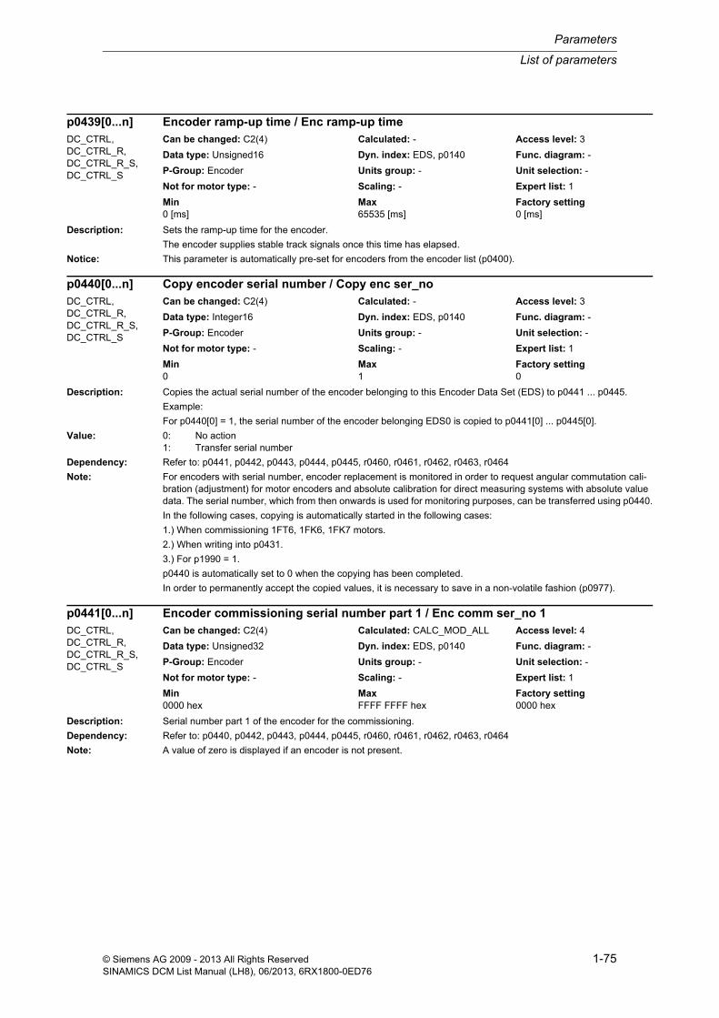
List of parameters
Parameters
1-75© Siemens AG 2009 - 2013 All Rights ReservedSINAMICS DCM List Manual (LH8), 06/2013, 6RX1800-0ED76
Description: Sets the ramp-up time for the encoder.
The encoder supplies stable track signals once this time has elapsed.
Notice: This parameter is automatically pre-set for encoders from the encoder list (p0400).
Description: Copies the actual serial number of the encoder belonging to this Encoder Data Set (EDS) to p0441 ... p0445.
Example:
For p0440[0] = 1, the serial number of the encoder belonging EDS0 is copied to p0441[0] ... p0445[0].
Value: 0: No action1: Transfer serial number
Dependency: Refer to: p0441, p0442, p0443, p0444, p0445, r0460, r0461, r0462, r0463, r0464
Note: For encoders with serial number, encoder replacement is monitored in order to request angular commutation cali-bration (adjustment) for motor encoders and absolute calibration for direct measuring systems with absolute value data. The serial number, which from then onwards is used for monitoring purposes, can be transferred using p0440.
In the following cases, copying is automatically started in the following cases:
1.) When commissioning 1FT6, 1FK6, 1FK7 motors.
2.) When writing into p0431.
3.) For p1990 = 1.
p0440 is automatically set to 0 when the copying has been completed.
In order to permanently accept the copied values, it is necessary to save in a non-volatile fashion (p0977).
Description: Serial number part 1 of the encoder for the commissioning.
Dependency: Refer to: p0440, p0442, p0443, p0444, p0445, r0460, r0461, r0462, r0463, r0464
Note: A value of zero is displayed if an encoder is not present.
p0439[0...n] Encoder ramp-up time / Enc ramp-up timeDC_CTRL, DC_CTRL_R, DC_CTRL_R_S, DC_CTRL_S
Can be changed: C2(4) Calculated: - Access level: 3
Data type: Unsigned16 Dyn. index: EDS, p0140 Func. diagram: -
P-Group: Encoder Units group: - Unit selection: -
Not for motor type: - Scaling: - Expert list: 1
Min Max Factory setting 0 [ms] 65535 [ms] 0 [ms]
p0440[0...n] Copy encoder serial number / Copy enc ser_noDC_CTRL, DC_CTRL_R, DC_CTRL_R_S, DC_CTRL_S
Can be changed: C2(4) Calculated: - Access level: 3
Data type: Integer16 Dyn. index: EDS, p0140 Func. diagram: -
P-Group: Encoder Units group: - Unit selection: -
Not for motor type: - Scaling: - Expert list: 1
Min Max Factory setting 0 1 0
p0441[0...n] Encoder commissioning serial number part 1 / Enc comm ser_no 1DC_CTRL, DC_CTRL_R, DC_CTRL_R_S, DC_CTRL_S
Can be changed: C2(4) Calculated: CALC_MOD_ALL Access level: 4
Data type: Unsigned32 Dyn. index: EDS, p0140 Func. diagram: -
P-Group: Encoder Units group: - Unit selection: -
Not for motor type: - Scaling: - Expert list: 1
Min Max Factory setting 0000 hex FFFF FFFF hex 0000 hex

Parameters
List of parameters
1-76 © Siemens AG 2009 - 2013 All Rights ReservedSINAMICS DCM List Manual (LH8), 06/2013, 6RX1800-0ED76
Description: Serial number part 2 of the encoder for the commissioning.
Dependency: Refer to: p0440, p0441, p0443, p0444, p0445, r0460, r0461, r0462, r0463, r0464
Note: A value of zero is displayed if an encoder is not present.
Description: Serial number part 3 of the encoder for the commissioning.
Dependency: Refer to: p0440, p0441, p0442, p0444, p0445, r0460, r0461, r0462, r0463, r0464
Note: A value of zero is displayed if an encoder is not present.
Description: Serial number part 4 of the encoder for the commissioning.
Dependency: Refer to: p0440, p0441, p0442, p0443, p0445, r0460, r0461, r0462, r0463, r0464
Note: A value of zero is displayed if an encoder is not present.
Description: Serial number part 5 of the encoder for the commissioning.
Dependency: Refer to: p0440, p0441, p0442, p0443, p0444, r0460, r0461, r0462, r0463, r0464
Note: A value of zero is displayed if an encoder is not present.
p0442[0...n] Encoder commissioning serial number part 2 / Enc comm ser_no 2DC_CTRL, DC_CTRL_R, DC_CTRL_R_S, DC_CTRL_S
Can be changed: C2(4) Calculated: CALC_MOD_ALL Access level: 4
Data type: Unsigned32 Dyn. index: EDS, p0140 Func. diagram: -
P-Group: Encoder Units group: - Unit selection: -
Not for motor type: - Scaling: - Expert list: 1
Min Max Factory setting 0000 hex FFFF FFFF hex 0000 hex
p0443[0...n] Encoder commissioning serial number part 3 / Enc comm ser_no 3DC_CTRL, DC_CTRL_R, DC_CTRL_R_S, DC_CTRL_S
Can be changed: C2(4) Calculated: CALC_MOD_ALL Access level: 4
Data type: Unsigned32 Dyn. index: EDS, p0140 Func. diagram: -
P-Group: Encoder Units group: - Unit selection: -
Not for motor type: - Scaling: - Expert list: 1
Min Max Factory setting 0000 hex FFFF FFFF hex 0000 hex
p0444[0...n] Encoder commissioning serial number part 4 / Enc comm ser_no 4DC_CTRL, DC_CTRL_R, DC_CTRL_R_S, DC_CTRL_S
Can be changed: C2(4) Calculated: CALC_MOD_ALL Access level: 4
Data type: Unsigned32 Dyn. index: EDS, p0140 Func. diagram: -
P-Group: Encoder Units group: - Unit selection: -
Not for motor type: - Scaling: - Expert list: 1
Min Max Factory setting 0000 hex FFFF FFFF hex 0000 hex
p0445[0...n] Encoder commissioning serial number part 5 / Enc comm ser_no 5DC_CTRL, DC_CTRL_R, DC_CTRL_R_S, DC_CTRL_S
Can be changed: C2(4) Calculated: CALC_MOD_ALL Access level: 4
Data type: Unsigned32 Dyn. index: EDS, p0140 Func. diagram: -
P-Group: Encoder Units group: - Unit selection: -
Not for motor type: - Scaling: - Expert list: 1
Min Max Factory setting 0000 hex FFFF FFFF hex 0000 hex

List of parameters
Parameters
1-77© Siemens AG 2009 - 2013 All Rights ReservedSINAMICS DCM List Manual (LH8), 06/2013, 6RX1800-0ED76
Description: Displays the effective filter time for a squarewave encoder.
The filter time is set using p0438.
Index: [0] = Encoder 1[1] = Encoder 2[2] = -
Dependency: Refer to: p0438
Note: A value of zero is displayed if an encoder is not present.
Description: Sets the measuring time for evaluating zero speed.
If no pulses are detected from track A/B during this time, a speed actual value of zero is output.
Dependency: Refer to: r0452
Note: This function is required for slow-running motors so that actual speeds close to zero can be output correctly.
Description: Displays the detected encoder configuration.
In this case, the encoder must automatically support the function (e.g. encoder with EnDat interface).
Index: [0] = Encoder 1[1] = Encoder 2[2] = -
r0452[0...2] Squarewave encoder filter time display / Enc t_filt displDC_CTRL, DC_CTRL_R, DC_CTRL_R_S, DC_CTRL_S
Can be changed: - Calculated: - Access level: 3
Data type: FloatingPoint32 Dyn. index: - Func. diagram: -
P-Group: Encoder Units group: - Unit selection: -
Not for motor type: - Scaling: - Expert list: 1
Min Max Factory setting - [µs] - [µs] - [µs]
p0453[0...n] Pulse encoder evaluation zero speed measuring time / Enc_ev n_0 t_measDC_CTRL, DC_CTRL_R, DC_CTRL_R_S, DC_CTRL_S
Can be changed: C2(4) Calculated: - Access level: 3
Data type: FloatingPoint32 Dyn. index: EDS, p0140 Func. diagram: -
P-Group: Encoder Units group: - Unit selection: -
Not for motor type: - Scaling: - Expert list: 1
Min Max Factory setting 0.10 [ms] 10000.00 [ms] 1000.00 [ms]
r0455[0...2] Encoder configuration recognized / Enc config actDC_CTRL, DC_CTRL_R, DC_CTRL_R_S, DC_CTRL_S
Can be changed: - Calculated: - Access level: 3
Data type: Unsigned32 Dyn. index: - Func. diagram: -
P-Group: Encoder Units group: - Unit selection: -
Not for motor type: - Scaling: - Expert list: 1
Min Max Factory setting - - -
Bit field: Bit Signal name 1 signal 0 signal FP00 Linear encoder Yes No -01 Absolute encoder Yes No -02 Multiturn encoder Yes No -03 Track A/B sq-wave Yes No -04 Track A/B sine Yes No -05 Track C/D Yes No -06 Hall sensor Yes No -08 EnDat encoder Yes No -09 SSI encoder Yes No -10 DRIVE-CLiQ encoder Yes No -11 Digital encoder Yes No -12 Equidistant zero mark Yes No -13 Irregular zero mark Yes No -14 Distance-coded zero mark Yes No -

Parameters
List of parameters
1-78 © Siemens AG 2009 - 2013 All Rights ReservedSINAMICS DCM List Manual (LH8), 06/2013, 6RX1800-0ED76
Dependency: Refer to: p0404
Note: ZM: Zero mark
This parameter is only used for diagnostics.
A value of zero is displayed if an encoder is not present.
Re bit 20, 21 (voltage level 5 V, voltage level 24 V):
The voltage level cannot be detected. Therefore, these bits are always set to 0.
Description: Displays the encoder configuration supported by the Sensor Module.
Index: [0] = Encoder 1[1] = Encoder 2[2] = -
Dependency: Refer to: p0404
Note: ZM: Zero mark
This parameter is only used for diagnostics.
A value of zero is displayed if an encoder is not present.
15 Commutation with zero mark (not ASM) Yes No -16 Acceleration Yes No -17 Track A/B analog Yes No -20 Voltage level 5 V Yes No -21 Voltage level 24 V Yes No -22 Remote sense (only SMC30) Yes No -23 Resolver excit. Yes No -
r0456[0...2] Encoder configuration supported / Enc_config suppDC_CTRL, DC_CTRL_R, DC_CTRL_R_S, DC_CTRL_S
Can be changed: - Calculated: - Access level: 3
Data type: Unsigned32 Dyn. index: - Func. diagram: -
P-Group: Encoder Units group: - Unit selection: -
Not for motor type: - Scaling: - Expert list: 1
Min Max Factory setting - - -
Bit field: Bit Signal name 1 signal 0 signal FP00 Linear encoder Yes No -01 Absolute encoder Yes No -02 Multiturn encoder Yes No -03 Track A/B sq-wave Yes No -04 Track A/B sine Yes No -05 Track C/D Yes No -06 Hall sensor Yes No -08 EnDat encoder Yes No -09 SSI encoder Yes No -10 DRIVE-CLiQ encoder Yes No -11 Digital encoder Yes No -12 Equidistant zero mark Yes No -13 Irregular zero mark Yes No -14 Distance-coded zero mark Yes No -15 Commutation with zero mark (not ASM) Yes No -16 Acceleration Yes No -17 Track A/B analog Yes No -20 Voltage level 5 V Yes No -21 Voltage level 24 V Yes No -22 Remote sense (only SMC30) Yes No -23 Resolver excit. Yes No -

List of parameters
Parameters
1-79© Siemens AG 2009 - 2013 All Rights ReservedSINAMICS DCM List Manual (LH8), 06/2013, 6RX1800-0ED76
Description: Sets the Sensor Module configuration.
Index: [0] = Encoder 1[1] = Encoder 2[2] = -
Dependency: Refer to: p0437, p0601
Note: A value of zero is displayed if an encoder is not present.
Re bit 11:
When the property is set, the following parameters can be changed without the actual value in the encoder interface becoming invalid (state r0481.14 = 1 "parking encoder active"):
p0314, p0315, p0430, p0431, p0441, p0442, p0443, p0444, p0445
r0458[0...2] Sensor Module properties / SM propertiesDC_CTRL, DC_CTRL_R, DC_CTRL_R_S, DC_CTRL_S
Can be changed: - Calculated: - Access level: 3
Data type: Unsigned32 Dyn. index: - Func. diagram: 4704
P-Group: Encoder Units group: - Unit selection: -
Not for motor type: - Scaling: - Expert list: 1
Min Max Factory setting - - -
Bit field: Bit Signal name 1 signal 0 signal FP00 Encoder data available Yes No -01 Motor data available Yes No -02 Temperature sensor connection available Yes No -03 Connection for PTC for motor with DRIVE-
CLiQ also availableYes No -
04 Module temperature available Yes No -05 Absolute encoder p0408/p0421 no power of
2Yes No -
06 Sensor Module permits parking/unparking Yes No -07 Hall sensor can be combined with actual
value inversionYes No -
08 Evaluation through several temperature channels possible
Yes No -
09 Encoder fault and its associated information available
Yes No -
10 Speed diagnostics in the Sensor Module Yes No -11 Configuring without park state possible Yes No -12 Extended functions available Yes No -13 Extended encoder fault handling Yes No -14 Extended singleturn/multiturn information
availableYes No -
15 Valuation figures available Yes No -16 Pole position identification Yes No -17 Burst oversampling Yes No -18 Continuous oversampling Yes No -19 Safety position actual value sensing Yes No -20 Extended speed calculation being used
(only SMC30)Yes No -
21 Zero mark tolerance Yes No -22 Rot pos adapt Yes No -23 Commutation with zero mark can be de-
selectedYes No -
24 Commutation with selected zero mark Yes No -25 Disconnection of encoder power supply on
parking supportedYes No -
26 Parking with temperature evaluation Yes No -27 SSI position value extrapolation Yes No -28 Cubic correction Yes No -29 Phase correction Yes No -30 Amplitude correction Yes No -31 Offset correction Yes No -

Parameters
List of parameters
1-80 © Siemens AG 2009 - 2013 All Rights ReservedSINAMICS DCM List Manual (LH8), 06/2013, 6RX1800-0ED76
Re bit 12:
The extended functions can be configured using p0437.
Re bit 13:
Encoder faults can be acknowledged via Gn_STW.15.
Re bit 14:
Only for internal Siemens use.
Re bit 23:
When the property is set, commutation with zero mark can be de-selected using p0430.23.
Re bit 24:
If the property is set, commutation to the selected zero mark can be carried out.
Description: Displays the extended properties supported by the Sensor Module.
Index: [0] = Encoder 1[1] = Encoder 2[2] = -
Dependency: Refer to: p0437
Note: A value of zero is displayed if an encoder is not present.
Re bit 09:
Parameter p0426 or p0439 has been modified. These functions are not supported by the connected Sensor Mod-ule.
r0459[0...2] Sensor Module properties extended / SM prop extDC_CTRL, DC_CTRL_R, DC_CTRL_R_S, DC_CTRL_S
Can be changed: - Calculated: - Access level: 3
Data type: Unsigned32 Dyn. index: - Func. diagram: -
P-Group: Encoder Units group: - Unit selection: -
Not for motor type: - Scaling: - Expert list: 1
Min Max Factory setting - - -
Bit field: Bit Signal name 1 signal 0 signal FP00 Data logger Yes No -01 Zero mark edge detection Yes No -02 Correction position actual value XIST1 Yes No -04 Edge evaluation bit 0 Yes No -05 Edge evaluation bit 1 Yes No -06 Freeze the speed actual value for dn/dt
errorsYes No -
07 Accumulate uncorrected encoder pulses Yes No -09 Function p0426, p0439 supported Yes No -10 Pulse/direction interface Yes No -11 Fault handling after PROFIdrive Yes No -12 Activate additional messages Yes No -13 Absolute position for incremental encoder
supportedYes No -
14 Spindle functionality Yes No -15 Additional temperature sensor available Yes No -16 Internal encoder temperature available Yes No -25 Deselect monitoring multiturn representa-
tion in Gx_XIST2Yes No -
26 Track monitoring de-selection Yes No -28 EnDat linear encoder monitoring incremen-
tal/absoluteYes No -
29 EnDat encoder initialization with high accu-racy
Yes No -
31 Analog unipolar track monitoring Yes No -
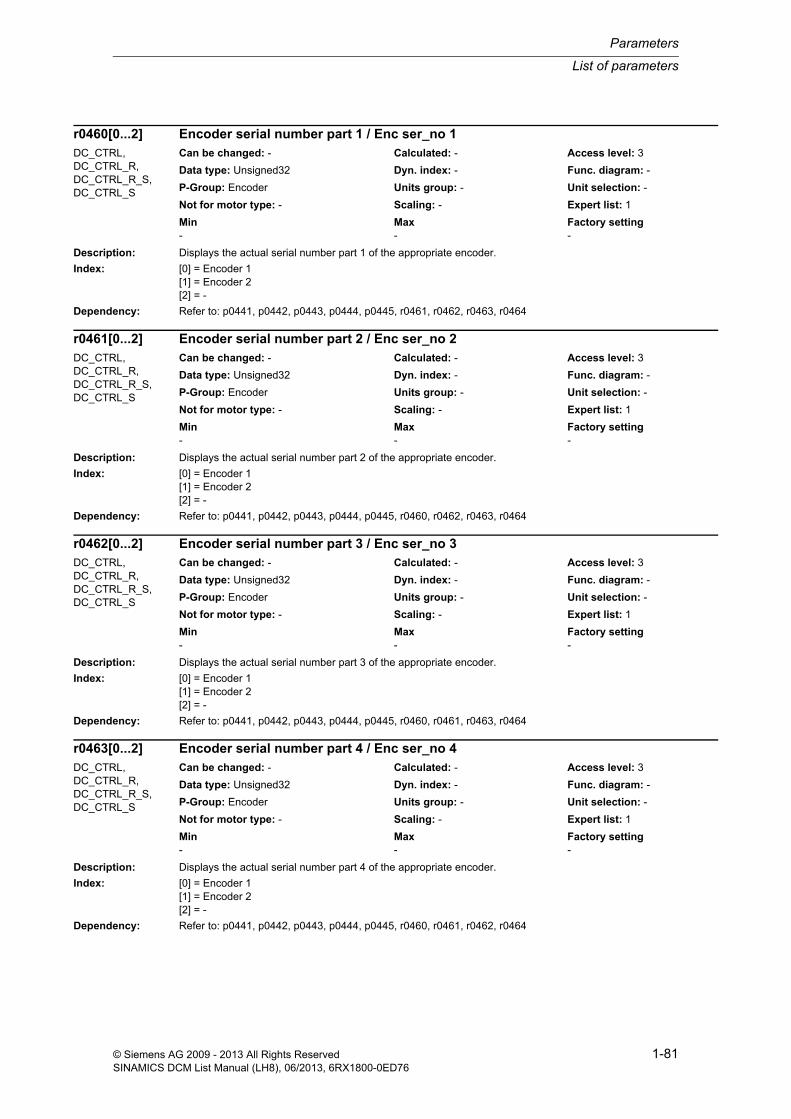
List of parameters
Parameters
1-81© Siemens AG 2009 - 2013 All Rights ReservedSINAMICS DCM List Manual (LH8), 06/2013, 6RX1800-0ED76
Description: Displays the actual serial number part 1 of the appropriate encoder.
Index: [0] = Encoder 1[1] = Encoder 2[2] = -
Dependency: Refer to: p0441, p0442, p0443, p0444, p0445, r0461, r0462, r0463, r0464
Description: Displays the actual serial number part 2 of the appropriate encoder.
Index: [0] = Encoder 1[1] = Encoder 2[2] = -
Dependency: Refer to: p0441, p0442, p0443, p0444, p0445, r0460, r0462, r0463, r0464
Description: Displays the actual serial number part 3 of the appropriate encoder.
Index: [0] = Encoder 1[1] = Encoder 2[2] = -
Dependency: Refer to: p0441, p0442, p0443, p0444, p0445, r0460, r0461, r0463, r0464
Description: Displays the actual serial number part 4 of the appropriate encoder.
Index: [0] = Encoder 1[1] = Encoder 2[2] = -
Dependency: Refer to: p0441, p0442, p0443, p0444, p0445, r0460, r0461, r0462, r0464
r0460[0...2] Encoder serial number part 1 / Enc ser_no 1DC_CTRL, DC_CTRL_R, DC_CTRL_R_S, DC_CTRL_S
Can be changed: - Calculated: - Access level: 3
Data type: Unsigned32 Dyn. index: - Func. diagram: -
P-Group: Encoder Units group: - Unit selection: -
Not for motor type: - Scaling: - Expert list: 1
Min Max Factory setting - - -
r0461[0...2] Encoder serial number part 2 / Enc ser_no 2DC_CTRL, DC_CTRL_R, DC_CTRL_R_S, DC_CTRL_S
Can be changed: - Calculated: - Access level: 3
Data type: Unsigned32 Dyn. index: - Func. diagram: -
P-Group: Encoder Units group: - Unit selection: -
Not for motor type: - Scaling: - Expert list: 1
Min Max Factory setting - - -
r0462[0...2] Encoder serial number part 3 / Enc ser_no 3DC_CTRL, DC_CTRL_R, DC_CTRL_R_S, DC_CTRL_S
Can be changed: - Calculated: - Access level: 3
Data type: Unsigned32 Dyn. index: - Func. diagram: -
P-Group: Encoder Units group: - Unit selection: -
Not for motor type: - Scaling: - Expert list: 1
Min Max Factory setting - - -
r0463[0...2] Encoder serial number part 4 / Enc ser_no 4DC_CTRL, DC_CTRL_R, DC_CTRL_R_S, DC_CTRL_S
Can be changed: - Calculated: - Access level: 3
Data type: Unsigned32 Dyn. index: - Func. diagram: -
P-Group: Encoder Units group: - Unit selection: -
Not for motor type: - Scaling: - Expert list: 1
Min Max Factory setting - - -
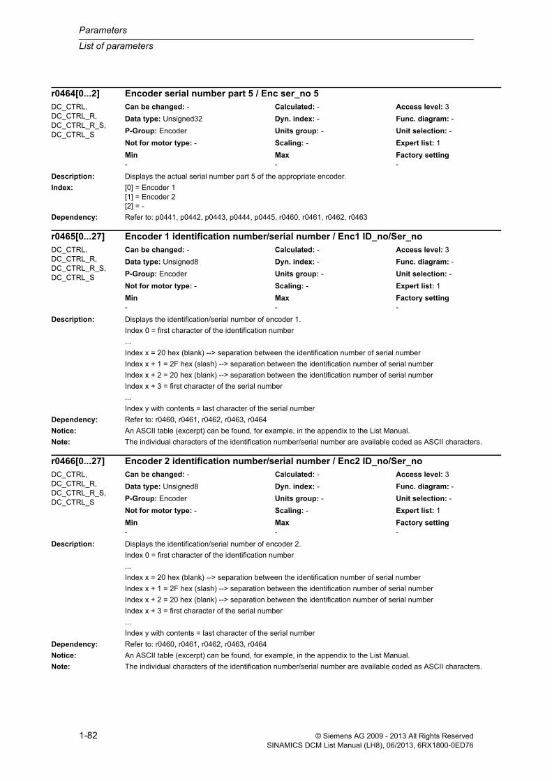
Parameters
List of parameters
1-82 © Siemens AG 2009 - 2013 All Rights ReservedSINAMICS DCM List Manual (LH8), 06/2013, 6RX1800-0ED76
Description: Displays the actual serial number part 5 of the appropriate encoder.
Index: [0] = Encoder 1[1] = Encoder 2[2] = -
Dependency: Refer to: p0441, p0442, p0443, p0444, p0445, r0460, r0461, r0462, r0463
Description: Displays the identification/serial number of encoder 1.
Index 0 = first character of the identification number
...
Index x = 20 hex (blank) --> separation between the identification number of serial number
Index x + 1 = 2F hex (slash) --> separation between the identification number of serial number
Index x + 2 = 20 hex (blank) --> separation between the identification number of serial number
Index x + 3 = first character of the serial number
...
Index y with contents = last character of the serial number
Dependency: Refer to: r0460, r0461, r0462, r0463, r0464
Notice: An ASCII table (excerpt) can be found, for example, in the appendix to the List Manual.
Note: The individual characters of the identification number/serial number are available coded as ASCII characters.
Description: Displays the identification/serial number of encoder 2.
Index 0 = first character of the identification number
...
Index x = 20 hex (blank) --> separation between the identification number of serial number
Index x + 1 = 2F hex (slash) --> separation between the identification number of serial number
Index x + 2 = 20 hex (blank) --> separation between the identification number of serial number
Index x + 3 = first character of the serial number
...
Index y with contents = last character of the serial number
Dependency: Refer to: r0460, r0461, r0462, r0463, r0464
Notice: An ASCII table (excerpt) can be found, for example, in the appendix to the List Manual.
Note: The individual characters of the identification number/serial number are available coded as ASCII characters.
r0464[0...2] Encoder serial number part 5 / Enc ser_no 5DC_CTRL, DC_CTRL_R, DC_CTRL_R_S, DC_CTRL_S
Can be changed: - Calculated: - Access level: 3
Data type: Unsigned32 Dyn. index: - Func. diagram: -
P-Group: Encoder Units group: - Unit selection: -
Not for motor type: - Scaling: - Expert list: 1
Min Max Factory setting - - -
r0465[0...27] Encoder 1 identification number/serial number / Enc1 ID_no/Ser_noDC_CTRL, DC_CTRL_R, DC_CTRL_R_S, DC_CTRL_S
Can be changed: - Calculated: - Access level: 3
Data type: Unsigned8 Dyn. index: - Func. diagram: -
P-Group: Encoder Units group: - Unit selection: -
Not for motor type: - Scaling: - Expert list: 1
Min Max Factory setting - - -
r0466[0...27] Encoder 2 identification number/serial number / Enc2 ID_no/Ser_noDC_CTRL, DC_CTRL_R, DC_CTRL_R_S, DC_CTRL_S
Can be changed: - Calculated: - Access level: 3
Data type: Unsigned8 Dyn. index: - Func. diagram: -
P-Group: Encoder Units group: - Unit selection: -
Not for motor type: - Scaling: - Expert list: 1
Min Max Factory setting - - -

List of parameters
Parameters
1-83© Siemens AG 2009 - 2013 All Rights ReservedSINAMICS DCM List Manual (LH8), 06/2013, 6RX1800-0ED76
Description: Displays the resolution of the absolute position for a linear absolute encoder.
Index: [0] = Encoder 1[1] = Encoder 2[2] = Encoder 3
Dependency: Refer to: p0422
Description: Displays the valid bits of the redundant coarse position value.
Index: [0] = Encoder 1[1] = Encoder 2[2] = -
Description: Displays the number of valid bits for the fine resolution of the redundant coarse position value.
Index: [0] = Encoder 1[1] = Encoder 2[2] = -
Description: Displays the number of relevant bits for the redundant coarse position value.
Index: [0] = Encoder 1[1] = Encoder 2[2] = -
r0469[0...2] Absolute encoder linear measuring step / Enc lin meas stepDC_CTRL, DC_CTRL_R, DC_CTRL_R_S, DC_CTRL_S
Can be changed: - Calculated: - Access level: 3
Data type: Unsigned32 Dyn. index: - Func. diagram: -
P-Group: Encoder Units group: - Unit selection: -
Not for motor type: - Scaling: - Expert list: 1
Min Max Factory setting - [nm] - [nm] - [nm]
r0470[0...2] Redundant coarse position value valid bits / Valid bitsDC_CTRL, DC_CTRL_R, DC_CTRL_R_S, DC_CTRL_S
Can be changed: - Calculated: - Access level: 3
Data type: Unsigned16 Dyn. index: - Func. diagram: -
P-Group: Encoder Units group: - Unit selection: -
Not for motor type: - Scaling: - Expert list: 1
Min Max Factory setting - - -
r0471[0...2] Redundant coarse position value fine resolution bits / Fine bitDC_CTRL, DC_CTRL_R, DC_CTRL_R_S, DC_CTRL_S
Can be changed: - Calculated: - Access level: 3
Data type: Integer16 Dyn. index: - Func. diagram: -
P-Group: Encoder Units group: - Unit selection: -
Not for motor type: - Scaling: - Expert list: 1
Min Max Factory setting - - -
r0472[0...2] Redundant coarse position value relevant bits / Relevant bitsDC_CTRL, DC_CTRL_R, DC_CTRL_R_S, DC_CTRL_S
Can be changed: - Calculated: - Access level: 3
Data type: Unsigned16 Dyn. index: - Func. diagram: -
P-Group: Encoder Units group: - Unit selection: -
Not for motor type: - Scaling: - Expert list: 1
Min Max Factory setting - - -

Parameters
List of parameters
1-84 © Siemens AG 2009 - 2013 All Rights ReservedSINAMICS DCM List Manual (LH8), 06/2013, 6RX1800-0ED76
Description: Displays the non safety-relevant measuring steps of POS1.
Index: [0] = Encoder 1[1] = Encoder 2[2] = Encoder 3
Dependency: Refer to: p0416
Description: Displays the encoder configuration for the redundant coarse position value.
Index: [0] = Encoder 1[1] = Encoder 2[2] = -
Description: Displays the bit number for the safe most significant bit (MSB) of the Gx_XIST1 coarse position.
Index: [0] = Encoder 1[1] = Encoder 2[2] = -
Note: MSB: Most Significant Bit
Description: Displays the position difference before the measuring gear between powering down and powering up.
r0473[0...2] Non safety-relevant measuring steps position value pos1 / nsrPos1DC_CTRL, DC_CTRL_R, DC_CTRL_R_S, DC_CTRL_S
Can be changed: - Calculated: - Access level: 3
Data type: Unsigned32 Dyn. index: - Func. diagram: -
P-Group: Encoder Units group: - Unit selection: -
Not for motor type: - Scaling: - Expert list: 1
Min Max Factory setting - - -
r0474[0...2] Redundant coarse position value configuration / Red pos configDC_CTRL, DC_CTRL_R, DC_CTRL_R_S, DC_CTRL_S
Can be changed: - Calculated: - Access level: 3
Data type: Unsigned32 Dyn. index: - Func. diagram: -
P-Group: Encoder Units group: - Unit selection: -
Not for motor type: - Scaling: - Expert list: 1
Min Max Factory setting - - -
Bit field: Bit Signal name 1 signal 0 signal FP00 Incrementer Yes No -01 Encoder CRC least significant byte first Yes No -02 Redundant coarse position val. most signifi-
cant bit left-alignedYes No -
04 Binary comparison not possible Yes No -
r0475[0...2] Gx_XIST1 coarse position safe most significant bit / Gx_XIST1 safe MSBDC_CTRL, DC_CTRL_R, DC_CTRL_R_S, DC_CTRL_S
Can be changed: - Calculated: - Access level: 3
Data type: Unsigned16 Dyn. index: - Func. diagram: -
P-Group: Encoder Units group: - Unit selection: -
Not for motor type: - Scaling: - Expert list: 1
Min Max Factory setting - - -
r0477[0...2] CO: Measuring gear position difference / Meas gear pos diffDC_CTRL, DC_CTRL_R, DC_CTRL_R_S, DC_CTRL_S
Can be changed: - Calculated: - Access level: 1
Data type: Integer32 Dyn. index: - Func. diagram: -
P-Group: Encoder Units group: - Unit selection: -
Not for motor type: - Scaling: - Expert list: 1
Min Max Factory setting - - -

List of parameters
Parameters
1-85© Siemens AG 2009 - 2013 All Rights ReservedSINAMICS DCM List Manual (LH8), 06/2013, 6RX1800-0ED76
Index: [0] = Encoder 1[1] = Encoder 2[2] = -
Note: The increments are displayed in the format the same as r0483. The position difference should be read in encoder increments.
Description: Displays the encoder actual position value Gn_XIST1 according to PROFIdrive for diagnostics.
In contrast to r0482, the value is updated in each DRIVE-CLiQ basic clock cycle and displayed with sign.
Index: [0] = Encoder 1[1] = Encoder 2[2] = -
Caution: Following ramping-up or after a data set changeover, the new value is present at connector inputs which are inter-connected to connector output r0479 and under certain circumstances take 100 ms to become available.
Reason:
These interconnections are updated in the background, unlike interconnections involving other connector outputs (e.g. CO: r0482).
The value is immediately available when non-cyclically reading r0479 (e.g. via the expert list).
Description: Sets the signal source for the encoder control word Gn_STW according to PROFIdrive.
Index: [0] = Encoder 1[1] = Encoder 2[2] = -
Note: When the function module "basic positioner" (r0108.4 = 1) is activated, the following BICO interconnection is estab-lished:
CI: p0480[0] = r2520[0], CI: p0480[1] = r2520[1] and CI: p0480[2] = r2520[2]
Description: Displays the encoder status word Gn_ZSW according to PROFIdrive.
Index: [0] = Encoder 1[1] = Encoder 2[2] = Encoder 3
r0479[0...2] CO: Diagnostics encoder position actual value Gn_XIST1 / Diag Gn_XIST1DC_CTRL, DC_CTRL_R, DC_CTRL_R_S, DC_CTRL_S
Can be changed: - Calculated: - Access level: 3
Data type: Integer32 Dyn. index: - Func. diagram: 4704
P-Group: Encoder Units group: - Unit selection: -
Not for motor type: - Scaling: - Expert list: 1
Min Max Factory setting - - -
p0480[0...2] CI: Encoder control word Gn_STW signal source / Enc Gn_STW S_srcDC_CTRL, DC_CTRL_R, DC_CTRL_R_S, DC_CTRL_S
Can be changed: T Calculated: - Access level: 3
Data type: Unsigned32 / Integer16 Dyn. index: - Func. diagram: 1580, 4720, 4750
P-Group: Encoder Units group: - Unit selection: -
Not for motor type: - Scaling: - Expert list: 1
Min Max Factory setting - - 0
r0481[0...2] CO: Encoder status word Gn_ZSW / Enc Gn_ZSWDC_CTRL, DC_CTRL_R, DC_CTRL_R_S, DC_CTRL_S
Can be changed: - Calculated: - Access level: 3
Data type: Unsigned16 Dyn. index: - Func. diagram: 4704, 4730
P-Group: Encoder Units group: - Unit selection: -
Not for motor type: - Scaling: - Expert list: 1
Min Max Factory setting - - -

Parameters
List of parameters
1-86 © Siemens AG 2009 - 2013 All Rights ReservedSINAMICS DCM List Manual (LH8), 06/2013, 6RX1800-0ED76
Note: Re bit 14:
Displays the acknowledgement for "activate parking encoder" (Gn_STW.14 = 1) or encoder position actual value (Gn_XIST1) invalid.
Re bit 14, 15:
r0481.14 = 1 and r0481.15 = 0 can have one of the following causes:
- the encoder is parked.
- the encoder is de-activated.
- the encoder is being commissioned.
- no parameterized encoder available.
- encoder data set is being changed over.
r0481.14 = 1 and r0481.15 = 1 has the following significance:
An encoder error has occurred and the encoder position actual value (Gn_XIST1) is invalid.
Description: Displays the encoder actual position value Gn_XIST1 according to PROFIdrive.
Index: [0] = Encoder 1[1] = Encoder 2[2] = -
Note: - this value is reset if necessary when the "parking encoder" (r0481.14) function is de-selected.
- in this value, the measuring gear (p0432, p0433) is only taken into account when the position tracking is activated (p0411.0 = 1).
- The update time for the position control (EPOS) corresponds to the position controller clock cycle p0115[4].
- The update time in isochronous operation corresponds to the bus cycle time r2064[1].
- The update time in isochronous operation and with position control (EPOS) corresponds to the position controller clock cycle p0115[4].
- The update time in non-isochronous operation or without position control (EPOS) comprises the following:
Update time = 4 * least common multiple (LCM) of all current controller clock cycles (p0115[0]) in the drive group (infeed + drives). The minimum update time is 1 ms.
Example 1: infeed, servo
Update time = 4 * LCM(250 µs, 125 µs) = 4 * 250 µs = 1 ms
Example 2: infeed, servo, vector
Update time = 4 * LCM(250 µs, 125 µs, 500 µs) = 4 * 500 µs = 2 ms
Bit field: Bit Signal name 1 signal 0 signal FP00 Function 1 active Yes No -01 Function 2 active Yes No -02 Function 3 active Yes No -03 Function 4 active Yes No -04 Value 1 Displayed in r0483 Not present -05 Value 2 Displayed in r0483 Not present -06 Value 3 Displayed in r0483 Not present -07 Value 4 Displayed in r0483 Not present -08 Measuring probe 1 deflected Yes No -09 Measuring probe 2 deflected Yes No -11 Encoder fault acknowledge active Yes No 967613 Absolute value cyclically Displayed in r0483 No -14 Parking encoder active Yes No -15 Encoder fault Displayed in r0483 None -
r0482[0...2] CO: Encoder actual position value Gn_XIST1 / Enc Gn_XIST1DC_CTRL, DC_CTRL_R, DC_CTRL_R_S, DC_CTRL_S
Can be changed: - Calculated: - Access level: 3
Data type: Unsigned32 Dyn. index: - Func. diagram: 1580, 4704, 4735
P-Group: Encoder Units group: - Unit selection: -
Not for motor type: - Scaling: - Expert list: 1
Min Max Factory setting - - -
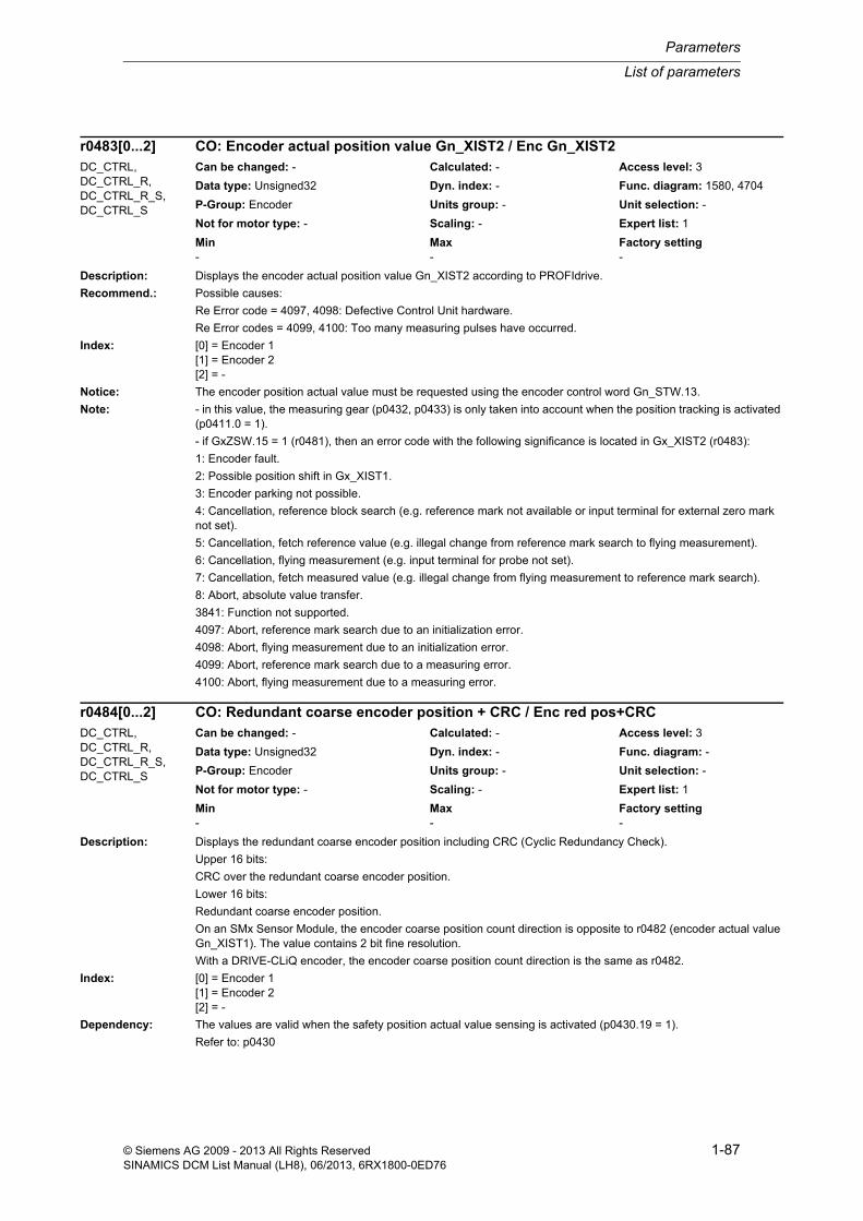
List of parameters
Parameters
1-87© Siemens AG 2009 - 2013 All Rights ReservedSINAMICS DCM List Manual (LH8), 06/2013, 6RX1800-0ED76
Description: Displays the encoder actual position value Gn_XIST2 according to PROFIdrive.
Recommend.: Possible causes:
Re Error code = 4097, 4098: Defective Control Unit hardware.
Re Error codes = 4099, 4100: Too many measuring pulses have occurred.
Index: [0] = Encoder 1[1] = Encoder 2[2] = -
Notice: The encoder position actual value must be requested using the encoder control word Gn_STW.13.
Note: - in this value, the measuring gear (p0432, p0433) is only taken into account when the position tracking is activated (p0411.0 = 1).
- if GxZSW.15 = 1 (r0481), then an error code with the following significance is located in Gx_XIST2 (r0483):
1: Encoder fault.
2: Possible position shift in Gx_XIST1.
3: Encoder parking not possible.
4: Cancellation, reference block search (e.g. reference mark not available or input terminal for external zero mark not set).
5: Cancellation, fetch reference value (e.g. illegal change from reference mark search to flying measurement).
6: Cancellation, flying measurement (e.g. input terminal for probe not set).
7: Cancellation, fetch measured value (e.g. illegal change from flying measurement to reference mark search).
8: Abort, absolute value transfer.
3841: Function not supported.
4097: Abort, reference mark search due to an initialization error.
4098: Abort, flying measurement due to an initialization error.
4099: Abort, reference mark search due to a measuring error.
4100: Abort, flying measurement due to a measuring error.
Description: Displays the redundant coarse encoder position including CRC (Cyclic Redundancy Check).
Upper 16 bits:
CRC over the redundant coarse encoder position.
Lower 16 bits:
Redundant coarse encoder position.
On an SMx Sensor Module, the encoder coarse position count direction is opposite to r0482 (encoder actual value Gn_XIST1). The value contains 2 bit fine resolution.
With a DRIVE-CLiQ encoder, the encoder coarse position count direction is the same as r0482.
Index: [0] = Encoder 1[1] = Encoder 2[2] = -
Dependency: The values are valid when the safety position actual value sensing is activated (p0430.19 = 1).
Refer to: p0430
r0483[0...2] CO: Encoder actual position value Gn_XIST2 / Enc Gn_XIST2DC_CTRL, DC_CTRL_R, DC_CTRL_R_S, DC_CTRL_S
Can be changed: - Calculated: - Access level: 3
Data type: Unsigned32 Dyn. index: - Func. diagram: 1580, 4704
P-Group: Encoder Units group: - Unit selection: -
Not for motor type: - Scaling: - Expert list: 1
Min Max Factory setting - - -
r0484[0...2] CO: Redundant coarse encoder position + CRC / Enc red pos+CRCDC_CTRL, DC_CTRL_R, DC_CTRL_R_S, DC_CTRL_S
Can be changed: - Calculated: - Access level: 3
Data type: Unsigned32 Dyn. index: - Func. diagram: -
P-Group: Encoder Units group: - Unit selection: -
Not for motor type: - Scaling: - Expert list: 1
Min Max Factory setting - - -

Parameters
List of parameters
1-88 © Siemens AG 2009 - 2013 All Rights ReservedSINAMICS DCM List Manual (LH8), 06/2013, 6RX1800-0ED76
Note: This absolute value does not change, contrary to r0482, when de-selecting the function "parking axis".
Description: Displays the raw value of the incremental encoder actual value before the measuring gear.
Index: [0] = Encoder 1[1] = Encoder 2[2] = -
Description: Displays the raw value of the absolute encoder actual value before the measuring gear.
Index: [0] = Encoder 1[1] = Encoder 2[2] = -
Description: Displays the encoder control word Gn_STW according to PROFIdrive for diagnostics.
Index: [0] = Encoder 1[1] = Encoder 2[2] = -
Notice: Information on Gn_STW/Gn_ZSW should be taken from the corresponding product documentation.
Note: The signal source for the encoder control word is set with p0480.
r0485[0...2] CO: Measuring gear encoder raw value incremental / Enc raw val incrDC_CTRL, DC_CTRL_R, DC_CTRL_R_S, DC_CTRL_S
Can be changed: - Calculated: - Access level: 1
Data type: Unsigned32 Dyn. index: - Func. diagram: -
P-Group: Encoder Units group: - Unit selection: -
Not for motor type: - Scaling: - Expert list: 1
Min Max Factory setting - - -
r0486[0...2] CO: Measuring gear encoder raw value absolute / Enc raw val absDC_CTRL, DC_CTRL_R, DC_CTRL_R_S, DC_CTRL_S
Can be changed: - Calculated: - Access level: 1
Data type: Unsigned32 Dyn. index: - Func. diagram: -
P-Group: Encoder Units group: - Unit selection: -
Not for motor type: - Scaling: - Expert list: 1
Min Max Factory setting - - -
r0487[0...2] Diagnostic encoder control word Gn_STW / Enc Gn_STWDC_CTRL, DC_CTRL_R, DC_CTRL_R_S, DC_CTRL_S
Can be changed: - Calculated: - Access level: 3
Data type: Unsigned16 Dyn. index: - Func. diagram: 1580, 4704, 4720, 4735
P-Group: Encoder Units group: - Unit selection: -
Not for motor type: - Scaling: - Expert list: 1
Min Max Factory setting - - -
Bit field: Bit Signal name 1 signal 0 signal FP00 Request function 1 Yes No -01 Request function 2 Yes No -02 Request function 3 Yes No -03 Request function 4 Yes No -04 Request command bit 0 Yes No -05 Request command bit 1 Yes No -06 Request command bit 2 Yes No -07 Flying measurement mode/search for refer-
ence markFlying measurement Reference marks -
13 Request absolute value cyclic Yes No -14 Request parking encoder Yes No -15 Request acknowledge encoder fault Yes No -

List of parameters
Parameters
1-89© Siemens AG 2009 - 2013 All Rights ReservedSINAMICS DCM List Manual (LH8), 06/2013, 6RX1800-0ED76
Description: Sets the behavior for the ENCODER fault response (motor encoder).
This means, for example, if an encoder fault occurs, encoderless operation can be automatically selected with a shutdown behavior that can be selected.
Value: 0: Encoder fault results in OFF21: Enc fault results in encoderless oper. and oper. continues2: Encoder fault results in encoderless operation and OFF13: Encoder fault results in encoderless operation and OFF34: Encoder fault results in an armature short-cct int/DC braking5: Enc fault results in encoderless op, operation continues, alarm
Dependency: The following parameters are relevant for encoderless operation.
Caution: For a value = 1, 2, 3, 5 the following applies:
- encoderless operation must have been started.
- if, for synchronous motors, an encoder fault occurs below the switchover speed p1755, when switching over to encoderless operation, the motor can stall.
For a value = 1, 5 the following applies:
- in spite of the motor encoder fault that has occurred, the motor continues to operate.
Note: For a value = 1, 2, 3, 5 the following applies:
- Refer to the status signal "encoderless operation due to a fault" (BO: r1407.13).
- If, when setting r1407.13, a different drive data set is selected (e.g. interconnection from p0820), then the open-loop or closed-loop control type p1300 of this data set must match that of the original data set (e.g. p1300 = 21). Encoderless closed-loop controlled operation is kept when changing over.
For a value = 4, the following applies:
- The value can only be set for all motor data sets when p1231 = 3, 4.
- For synchronous motors, an armature short circuit is initiated on an encoder fault.
- For induction motors, DC braking is initiated on an encoder fault. DC braking must be commissioned (p1232, p1233, p1234).
For a value = 5, the following applies:
Same function as for value = 1. However, encoder faults are output as alarm and the message bit "Fault active" (r2139.3) is not set. The encoder fault has to be acknowledged via the encoder interface in order to resume opera-tion with encoder.
Description: Sets the maximum permissible speed difference within the current controller sampling time for squarewave encod-ers.
When the value is exceeded, depending on p0491, either encoderless closed-loop speed/torque control is selected or the drive is powered down.
Note: For a value of 0.0, the speed change monitoring is disabled.
if the set maximum speed difference is only exceeded for one sampling time of the current controller, then an appropriate alarm is output. However, if the maximum speed difference is exceeded over several sampling times, then a corresponding fault is output.
p0491 Motor encoder fault response ENCODER / Fault resp ENCODERDC_CTRL, DC_CTRL_R, DC_CTRL_R_S, DC_CTRL_S
Can be changed: T Calculated: - Access level: 3
Data type: Integer16 Dyn. index: - Func. diagram: -
P-Group: Encoder Units group: - Unit selection: -
Not for motor type: - Scaling: - Expert list: 1
Min Max Factory setting 0 5 0
p0492 Square-wave encoder maximum speed difference per sampling cycle / n_dif max/samp_cyc
DC_CTRL, DC_CTRL_R, DC_CTRL_R_S, DC_CTRL_S
Can be changed: U, T Calculated: CALC_MOD_REG Access level: 3
Data type: FloatingPoint32 Dyn. index: - Func. diagram: -
P-Group: Encoder Units group: - Unit selection: -
Not for motor type: - Scaling: - Expert list: 1
Min Max Factory setting 0.00 [rpm] 210000.00 [rpm] 0.00 [rpm]

Parameters
List of parameters
1-90 © Siemens AG 2009 - 2013 All Rights ReservedSINAMICS DCM List Manual (LH8), 06/2013, 6RX1800-0ED76
Description: Selects the trace signal to be output in r0497, r0498 and r0499 for encoder diagnostics.
Value: 0: Inactive1: r0497: Mechanical revolution10: r0498: Raw value track A, r0499: Raw value track B11: r0498: Fine position X (-A/2), r0499: Fine position Y (-B/2)12: r0498: Fine position Phi, r0499: -13: r0498: Offset correction X, r0499: Offset correction Y14: r0498: Phase correction X, r0499: Amplitude correction Y15: r0498: Cubic correction X, r0499: Fine position X16: r0498: oversampling channel A, r0499: oversampling channel B17: r0498: fan-out amount, r0499: fan-out number18: r0498: Oversampling angle, r0499: Oversampling amount20: r0498: Raw value track C, r0499: Raw value track D21: r0498: CD position X (-D/2), r0499: CD position Y (C/2)22: r0498: CD position Phi, r0499: CD pos. Phi - mech. revolution23: r0497: Zero mark status24: r0498: Raw value track R, r0499: Zero mark status25: r0498: Raw value track A, r0499: Raw value track R30: r0497: Absolute position serial31: r0497: Absolute position incremental32: r0497: Zero mark position33: r0497: Correction absolute position difference40: r0498: Raw temperature, r0499: Temperature in 0.1 °C41: r0498: Resistance in 0.1 Ohm, r0499: Temperature in 0.1 °C42: r0497: Resistance 2500 Ohm51: r0497: Absolute speed difference (dn/dt)52: r0497: Xact1 corrected quadrants60: Analog sensor: r0498: raw val chann. A, r0499: raw val chann. B61: Analog sensor: r0498: fine pos chann. A,r0499: fine pos chann. B62: Analog sensor: r0498: Fine pos before characteristic, r0499: -70: Resolver: r0498: Transformation ratio, r0499: phase80: Spindle: r0498: Sensor S1 (raw), r0499: Sensor S4 (raw)81: Spindle: r0498: Sensor S5 (raw), r0499: -85: Spindle: r0498: Sensor S1 (cal), r0499: Sensor S4 (cal)86: Spindle: r0498: Sensor S5 (cal), r0499: -
Index: [0] = Encoder 1[1] = Encoder 2[2] = -
Dependency: Refer to: r0497, r0498, r0499
Notice: The setting option depends on the following properties:
Sensor Module type, hardware version, firmware version (Sensor Module and Control Units), order number (last digit).
Not all combinations are supported.
Note: Re p0496 = 1: 360 ° <--> 2^32
Re p0496 = 10 (resolver): 2900 mV <--> 26214 dec
Re p0496 = 10, 20 (sin/cos 1 Vpp, EnDat): 500 mV <--> 21299 dec
Re p0496 = 11 (resolver): 2900 mV <--> 13107 dec, internal processor offset is corrected
Re p0496 = 11, 21 (sin/cos 1 Vpp, EnDat): 500 mV <--> 10650 dec, internal processor offset is corrected
Re p0496 = 12: 180 ° fine position <--> 32768 dec
Re p0496 = 13 (resolver): 2900 mV <--> 13107 dec
Re p0496 = 13 (sin/cos 1 Vpp, EnDat): 500 mV <--> 10650 dec
p0496[0...2] Encoder diagnostic signal selection / Enc diag selectDC_CTRL, DC_CTRL_R, DC_CTRL_R_S, DC_CTRL_S
Can be changed: U, T Calculated: - Access level: 4
Data type: Integer16 Dyn. index: - Func. diagram: -
P-Group: Encoder Units group: - Unit selection: -
Not for motor type: - Scaling: - Expert list: 1
Min Max Factory setting 0 86 0

List of parameters
Parameters
1-91© Siemens AG 2009 - 2013 All Rights ReservedSINAMICS DCM List Manual (LH8), 06/2013, 6RX1800-0ED76
Re p0496 = 14: 1 ° <--> 286 dec, 100% <--> 16384 dec
Re p0496 = 15: 100 % <--> 16384 dec
Re p0496 = 16: (resolver): channel A: 2900 mV <--> 26214 dec, channel B: 2900 mV <--> 26214 dec
Re p0496 = 16: (sin/cos 1 Vpp, EnDat) channel A: 500 mV <--> 21299 dec, channel B: 500 mV <--> 21299 dec
Re p0496 = 17 (resolver): absolute value: 2900 mV <--> 13107 dec, number: 1 ... 8
Re p0496 = 17 (sin/cos 1 Vpp, EnDat): absolute value 500 mV <--> 10650 dec, number: 1 ... 8
Re p0496 = 18 (resolver): angle: signal period <--> 2^16, absolute value: 2900 mV <--> 13107 dec
Re p0496 = 18 (sin/cos 1 Vpp, EnDat): angle: signal period <--> 2^16, absolute value: 500 mV <--> 10650 dec
Re p0496 = 22: 180 ° <--> 32768 dec
Re p0496 = 23, 24: r0497.31 (r0499.15) set for at least 1 current controller cycle when encoder zero mark detected
Re p0496 = 24, 25: 500 mV <--> 21299 dec
Re p0496 = 30: Rotary: 1 singleturn measuring step <--> 1 dec, linear: 1 measuring step <--> 1 dec
Re p0496 = 31: Absolute position, incremental in 1/4 encoder pulses
Re p0496 = 32: Zero mark position in 1/4 encoder pulses
Re p0496 = 33: counter offset absolute value in 1/4 encoder pulses
Re p0496 = 40: r0498 <--> (R_KTY/1 kOhm - 0.9) * 32768
Re p0496 = 42: 2500 Ohm <--> 2^32
Re p0496 = 51: 1 rpm <--> 1000 dec
Re p0496 = 52: In 1/4 encoder pulses
Re p0496 = 60: voltage, channel A in mV, voltage, channel B in mV
Re p0496 = 61: Channel A: encoder periods <--> 2^16, channel B: encoder periods <--> 2^16
Re p0496 = 62: encoder periods <--> 2^16
Re p0496 = 70: r: 100% <--> 10000 dec, phase: 180 ° <--> 18000 dec
Re p0496 = 80, 81, 85, 86: 1V <--> 1000 inc
Description: Displays the trace signal for encoder diagnostics (double word).
The signal to be output is selected in p0496.
Index: [0] = Encoder 1[1] = Encoder 2[2] = -
Dependency: Refer to: p0496, r0498, r0499
Description: Displays the trace signal for encoder diagnostics (low component).
The signal to be output is selected in p0496.
Index: [0] = Encoder 1[1] = Encoder 2[2] = -
Dependency: Refer to: p0496, r0497, r0499
r0497[0...2] CO: Encoder diagnostic signal double word / Enc diag DWDC_CTRL, DC_CTRL_R, DC_CTRL_R_S, DC_CTRL_S
Can be changed: - Calculated: - Access level: 4
Data type: Unsigned32 Dyn. index: - Func. diagram: -
P-Group: Encoder Units group: - Unit selection: -
Not for motor type: - Scaling: - Expert list: 1
Min Max Factory setting - - -
r0498[0...2] CO: Encoder diagnostic signal low word / Enc diag low wordDC_CTRL, DC_CTRL_R, DC_CTRL_R_S, DC_CTRL_S
Can be changed: - Calculated: - Access level: 4
Data type: Integer16 Dyn. index: - Func. diagram: -
P-Group: Encoder Units group: - Unit selection: -
Not for motor type: - Scaling: - Expert list: 1
Min Max Factory setting - - -

Parameters
List of parameters
1-92 © Siemens AG 2009 - 2013 All Rights ReservedSINAMICS DCM List Manual (LH8), 06/2013, 6RX1800-0ED76
Description: Displays the trace signal for encoder diagnostics (high component).
The signal to be output is selected in p0496.
Index: [0] = Encoder 1[1] = Encoder 2[2] = -
Dependency: Refer to: p0496, r0497, r0498
Description: Selects the units for the parameters of the technology controller.
For p0595 = 1, 2, the reference quantity set in p0596 is not active.
Value: 1: %2: 1 referred no dimensions3: bar4: °C5: Pa6: ltr/s7: m³/s8: ltr/min9: m³/min10: ltr/h11: m³/h12: kg/s13: kg/min14: kg/h15: t/min16: t/h17: N18: kN19: Nm20: psi21: °F22: gallon/s23: inch³/s24: gallon/min25: inch³/min26: gallon/h27: inch³/h28: lb/s29: lb/min30: lb/h31: lbf32: lbf ft
r0499[0...2] CO: Encoder diagnostic signal high word / Enc diag high wordDC_CTRL, DC_CTRL_R, DC_CTRL_R_S, DC_CTRL_S
Can be changed: - Calculated: - Access level: 4
Data type: Integer16 Dyn. index: - Func. diagram: -
P-Group: Encoder Units group: - Unit selection: -
Not for motor type: - Scaling: - Expert list: 1
Min Max Factory setting - - -
p0595 Technological unit selection / Tech unit selectDC_CTRL (Tech_ctrl), DC_CTRL_R (Tech_ctrl), DC_CTRL_R_S (Tech_ctrl), DC_CTRL_S (Tech_ctrl)
Can be changed: C2(5) Calculated: - Access level: 1
Data type: Integer16 Dyn. index: - Func. diagram: -
P-Group: Applications Units group: - Unit selection: -
Not for motor type: - Scaling: - Expert list: 1
Min Max Factory setting 1 32 1

List of parameters
Parameters
1-93© Siemens AG 2009 - 2013 All Rights ReservedSINAMICS DCM List Manual (LH8), 06/2013, 6RX1800-0ED76
Dependency: Only the unit of the technology controller parameters are switched over (unit group 9_1).
Refer to: p0596
Note: When switching over from % into another unit, the following sequence applies:
- set p0596
- set p0595 to the required unit
Description: Sets the reference quantity for the technological units.
When changing over using changeover parameter p0595 to absolute units, all of the parameters involved refer to the reference quantity.
Dependency: Refer to: p0595
Notice: When changing over from one technological unit into another, or when changing the reference parameter, a changeover is not made.
Description: Sets the sensor type for the motor temperature monitoring.
Value: 0: No sensor2: KTY84
Dependency: Refer to: r0458
Description: Runs the corresponding macro files.
The binector inputs of the corresponding command data set are appropriately interconnected.
The selected macro file must be available on the memory card/device memory.
Example:
p0700 = 6 --> macro file PM000006.ACX is run.
Dependency: Refer to: p0015, p1000, p1500, r8571
Caution: When executing a specific macro, the corresponding programmed settings are made and become active.
Notice: No errors were issued during quick commissioning (p3900 = 1) when writing to parameters of the QUICK_IBN group!
p0596 Technological unit reference quantity / Tech unit ref qtyDC_CTRL (Tech_ctrl), DC_CTRL_R (Tech_ctrl), DC_CTRL_R_S (Tech_ctrl), DC_CTRL_S (Tech_ctrl)
Can be changed: T Calculated: - Access level: 1
Data type: FloatingPoint32 Dyn. index: - Func. diagram: -
P-Group: - Units group: - Unit selection: -
Not for motor type: - Scaling: - Expert list: 1
Min Max Factory setting 0.01 340.28235E36 1.00
p0601[0...n] Motor temperature sensor type / Mot_temp_sens typeDC_CTRL, DC_CTRL_R, DC_CTRL_R_S, DC_CTRL_S
Can be changed: C2(3), U, T Calculated: - Access level: 2
Data type: Integer16 Dyn. index: MDS Func. diagram: -
P-Group: Motor Units group: - Unit selection: -
Not for motor type: - Scaling: - Expert list: 1
Min Max Factory setting 0 2 0
p0700[0...n] Macro Binector Input (BI) / Macro BIDC_CTRL, DC_CTRL_R, DC_CTRL_R_S, DC_CTRL_S
Can be changed: C2(1), T Calculated: - Access level: 1
Data type: Unsigned32 Dyn. index: CDS, p0170 Func. diagram: -
P-Group: Commands Units group: - Unit selection: -
Not for motor type: - Scaling: - Expert list: 1
Min Max Factory setting 0 999999 0

Parameters
List of parameters
1-94 © Siemens AG 2009 - 2013 All Rights ReservedSINAMICS DCM List Manual (LH8), 06/2013, 6RX1800-0ED76
Note: The macros in the specified directory are displayed in r8571. r8571 is not in the expert list of the commissioning software.
Macros available as standard are described in the technical documentation of the particular product.
BI: Binector Input
CDS: Command Data Set
Description: Runs the corresponding macro files.
The selected macro file must be available on the memory card/device memory.
Example:
p0700 = 6 --> macro file PM000006.ACX is run.
Dependency: Refer to: r8571
Caution: When executing a specific macro, the corresponding programmed settings are made and become active.
Notice: No errors were issued during quick commissioning (p3900 = 1) when writing to parameters of the QUICK_IBN group!
Note: The macros in the specified directory are displayed in r8571. r8571 is not in the expert list of the commissioning software.
Macros available as standard are described in the technical documentation of the particular product.
BI: Binector Input
CDS: Command Data Set
Description: Sets the number for data transfer of a parameter backup from/to memory card.
Transfer from memory card to device memory (p0804 = 1):
- Sets the source of parameter backup (e.g. p0802 = 48 --> PS048xxx.ACX is the source).
Transfer from non-volatile device memory to memory card (p0804 = 2):
- Sets the target of parameter backup (e.g. p0802 = 23 --> PS023xxx.ACX is the target).
Dependency: Refer to: p0803, p0804
Notice: If the data between the volatile and non-volatile device memories differ, then it may be necessary to save the data on the memory card in a non-volatile fashion prior to the transfer (e.g. p0971 = 1).
Description: Sets the number for data transfer of a parameter backup from/to device memory.
Transfer from memory card to device memory (p0804 = 1):
- Sets the target of the parameter backup (e.g. p0803 = 10 --> PS010xxx.ACX is the target).
p0700 Macro Binector Input (BI) for TMs / Macro BI TMTM15DI_DO, TM31 Can be changed: C2(1), T Calculated: - Access level: 1
Data type: Unsigned32 Dyn. index: - Func. diagram: -
P-Group: Commands Units group: - Unit selection: -
Not for motor type: - Scaling: - Expert list: 1
Min Max Factory setting 0 999999 0
p0802 Data transfer: memory card as source/target / mem_card src/targCU_DC, CU_DC_R, CU_DC_R_S, CU_DC_S
Can be changed: T Calculated: - Access level: 3
Data type: Integer16 Dyn. index: - Func. diagram: -
P-Group: - Units group: - Unit selection: -
Not for motor type: - Scaling: - Expert list: 1
Min Max Factory setting 0 100 0
p0803 Data transfer: device memory as source/target / Dev_mem src/targCU_DC, CU_DC_R, CU_DC_R_S, CU_DC_S
Can be changed: T Calculated: - Access level: 3
Data type: Integer16 Dyn. index: - Func. diagram: -
P-Group: - Units group: - Unit selection: -
Not for motor type: - Scaling: - Expert list: 1
Min Max Factory setting 0 20 0
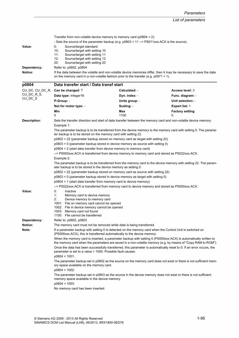
List of parameters
Parameters
1-95© Siemens AG 2009 - 2013 All Rights ReservedSINAMICS DCM List Manual (LH8), 06/2013, 6RX1800-0ED76
Transfer from non-volatile device memory to memory card (p0804 = 2):
- Sets the source of the parameter backup (e.g. p0803 = 11 --> PS011xxx.ACX is the source).
Value: 0: Source/target standard10: Source/target with setting 1011: Source/target with setting 1112: Source/target with setting 1220: Source/target with setting 20
Dependency: Refer to: p0802, p0804
Notice: If the data between the volatile and non-volatile device memories differ, then it may be necessary to save the data on the memory card in a non-volatile fashion prior to the transfer (e.g. p0971 = 1).
Description: Sets the transfer direction and start of data transfer between the memory card and non-volatile device memory.
Example 1:
The parameter backup is to be transferred from the device memory to the memory card with setting 0. The parame-ter backup is to be stored on the memory card with setting 22.
p0802 = 22 (parameter backup stored on memory card as target with setting 22)
p0803 = 0 (parameter backup stored in device memory as source with setting 0)
p0804 = 2 (start data transfer from device memory to memory card)
--> PS000xxx.ACX is transferred from device memory to memory card and stored as PS022xxx.ACX.
Example 2:
The parameter backup is to be transferred from the memory card to the device memory with setting 22. The param-eter backup is to be stored in the device memory as setting 0.
p0802 = 22 (parameter backup stored on memory card as source with setting 22)
p0803 = 0 (parameter backup stored in device memory as target with setting 0)
p0804 = 1 (start data transfer from memory card to device memory)
--> PS022xxx.ACX is transferred from memory card to device memory and stored as PS000xxx.ACX.
Value: 0: Inactive1: Memory card to device memory2: Device memory to memory card1001: File on memory card cannot be opened1002: File in device memory cannot be opened1003: Memory card not found1100: File cannot be transferred
Dependency: Refer to: p0802, p0803
Notice: The memory card must not be removed while data is being transferred.
Note: If a parameter backup with setting 0 is detected on the memory card when the Control Unit is switched on (PS000xxx.ACX), this is transferred automatically to the device memory.
When the memory card is inserted, a parameter backup with setting 0 (PS000xxx.ACX) is automatically written to the memory card when the parameters are saved in a non-volatile memory (e.g. by means of "Copy RAM to ROM").
Once the data has been successfully transferred, this parameter is automatically reset to 0. If an error occurs, the parameter is set to a value > 1000. Possible fault causes:
p0804 = 1001:
The parameter backup set in p0802 as the source on the memory card does not exist or there is not sufficient mem-ory space available on the memory card.
p0804 = 1002:
The parameter backup set in p0803 as the source in the device memory does not exist or there is not sufficient memory space available in the device memory.
p0804 = 1003:
No memory card has been inserted.
p0804 Data transfer start / Data transf startCU_DC, CU_DC_R, CU_DC_R_S, CU_DC_S
Can be changed: T Calculated: - Access level: 3
Data type: Integer16 Dyn. index: - Func. diagram: -
P-Group: - Units group: - Unit selection: -
Not for motor type: - Scaling: - Expert list: 1
Min Max Factory setting 0 1100 0

Parameters
List of parameters
1-96 © Siemens AG 2009 - 2013 All Rights ReservedSINAMICS DCM List Manual (LH8), 06/2013, 6RX1800-0ED76
Description: Sets the signal source to block the master control.
Dependency: Refer to: r0807
Note: The commissioning software (drive control panel) uses the master control, for example.
Description: Displays what has the master control.
The drive can be controlled via the BICO interconnection or from external (e.g. the commissioning software).
Dependency: Refer to: p0806
Notice: The master control only influences control word 1 and speed setpoint 1. Other control words/setpoints can be trans-ferred from another automation device.
Note: Bit 0 = 0: BICO interconnection active
Bit 0 = 1: Master control for PC/AOP
The commissioning software (drive control panel) uses the master control, for example.
Description: Copies one Command Data Set (CDS) into another.
Index: [0] = Source Command Data Set[1] = Target Command Data Set[2] = Start copying procedure
Note: Procedure:
1. In Index 0, enter which command data set should be copied.
2. In Index 1, enter the command data set that is to be copied into.
3. Start copying: Set index 2 from 0 to 1.
p0809[2] is automatically set to 0 when copying is completed.
p0806 BI: Inhibit master control / PcCtrl inhibitDC_CTRL, DC_CTRL_R, DC_CTRL_R_S, DC_CTRL_S
Can be changed: T Calculated: - Access level: 3
Data type: Unsigned32 / Binary Dyn. index: - Func. diagram: -
P-Group: Commands Units group: - Unit selection: -
Not for motor type: - Scaling: - Expert list: 1
Min Max Factory setting - - 0
r0807.0 BO: Master control active / PcCtrl activeDC_CTRL, DC_CTRL_R, DC_CTRL_R_S, DC_CTRL_S
Can be changed: - Calculated: - Access level: 2
Data type: Unsigned8 Dyn. index: - Func. diagram: 2580, 3113, 3130
P-Group: Displays, signals Units group: - Unit selection: -
Not for motor type: - Scaling: - Expert list: 1
Min Max Factory setting - - -
Bit field: Bit Signal name 1 signal 0 signal FP00 Master control active Yes No 5030,
6031
p0809[0...2] Copy Command Data Set CDS / Copy CDSDC_CTRL, DC_CTRL_R, DC_CTRL_R_S, DC_CTRL_S
Can be changed: T Calculated: - Access level: 2
Data type: Unsigned8 Dyn. index: - Func. diagram: 8560
P-Group: Commands Units group: - Unit selection: -
Not for motor type: - Scaling: - Expert list: 1
Min Max Factory setting 0 15 0

List of parameters
Parameters
1-97© Siemens AG 2009 - 2013 All Rights ReservedSINAMICS DCM List Manual (LH8), 06/2013, 6RX1800-0ED76
Description: Sets the signal source to select the Command Data Set bit 0 (CDS bit 0).
Dependency: Refer to: r0050, r0836
Notice: The parameter may be protected as a result of p0922 or p2079 and cannot be changed.
Note: The Command Data Set selected using the binector inputs is displayed in r0836.
The currently effective command data set is displayed in r0050.
A Command Data Set can be copied using p0809.
Description: Copies one Drive Data Set (DDS) into another.
Index: [0] = Source Drive Data Set[1] = Target Drive Data Set[2] = Start copying procedure
Note: Procedure:
1. In Index 0, enter which drive data set is to be copied.
2. In Index 1, enter the drive data set data that is to be copied into.
3. Start copying: Set index 2 from 0 to 1.
p0819[2] is automatically set to 0 when copying is completed.
Description: Sets the signal source to select the Drive Data Set, bit 0 (DDS, bit 0).
Dependency: Refer to: r0051, r0837
Notice: The parameter may be protected as a result of p0922 or p2079 and cannot be changed.
Description: Sets the signal source to select the Drive Data Set, bit 1 (DDS, bit 1).
Dependency: Refer to: r0051, r0837
Notice: The parameter may be protected as a result of p0922 or p2079 and cannot be changed.
p0810 BI: Command data set selection CDS bit 0 / CDS select bit 0DC_CTRL, DC_CTRL_R, DC_CTRL_R_S, DC_CTRL_S
Can be changed: T Calculated: - Access level: 3
Data type: Unsigned32 / Binary Dyn. index: - Func. diagram: 8560
P-Group: Commands Units group: - Unit selection: -
Not for motor type: - Scaling: - Expert list: 1
Min Max Factory setting - - 0
p0819[0...2] Copy Drive Data Set DDS / Copy DDSDC_CTRL, DC_CTRL_R, DC_CTRL_R_S, DC_CTRL_S
Can be changed: C2(15) Calculated: - Access level: 2
Data type: Unsigned8 Dyn. index: - Func. diagram: 8565
P-Group: Data sets Units group: - Unit selection: -
Not for motor type: - Scaling: - Expert list: 1
Min Max Factory setting 0 31 0
p0820[0...n] BI: Drive Data Set selection DDS bit 0 / DDS select bit 0DC_CTRL, DC_CTRL_R, DC_CTRL_R_S, DC_CTRL_S
Can be changed: C2(15), T Calculated: - Access level: 3
Data type: Unsigned32 / Binary Dyn. index: CDS, p0170 Func. diagram: 8565, 8570
P-Group: Data sets Units group: - Unit selection: -
Not for motor type: - Scaling: - Expert list: 1
Min Max Factory setting - - 0
p0821[0...n] BI: Drive Data Set selection DDS bit 1 / DDS select bit 1DC_CTRL, DC_CTRL_R, DC_CTRL_R_S, DC_CTRL_S
Can be changed: C2(15), T Calculated: - Access level: 3
Data type: Unsigned32 / Binary Dyn. index: CDS, p0170 Func. diagram: 8565
P-Group: Data sets Units group: - Unit selection: -
Not for motor type: - Scaling: - Expert list: 1
Min Max Factory setting - - 0
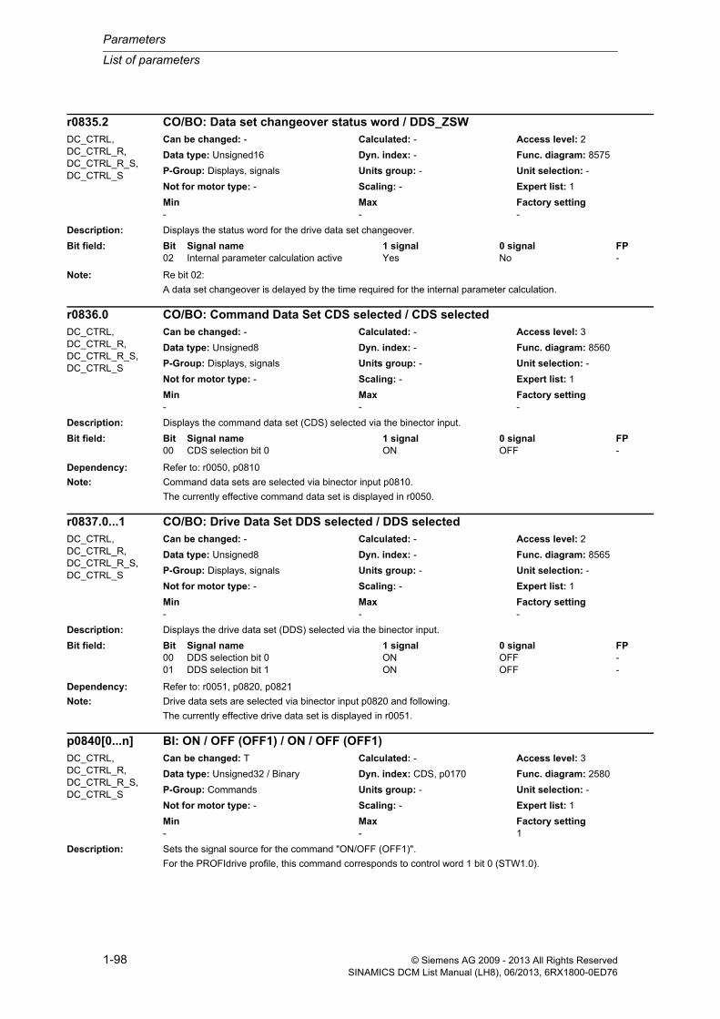
Parameters
List of parameters
1-98 © Siemens AG 2009 - 2013 All Rights ReservedSINAMICS DCM List Manual (LH8), 06/2013, 6RX1800-0ED76
Description: Displays the status word for the drive data set changeover.
Note: Re bit 02:
A data set changeover is delayed by the time required for the internal parameter calculation.
Description: Displays the command data set (CDS) selected via the binector input.
Dependency: Refer to: r0050, p0810
Note: Command data sets are selected via binector input p0810.
The currently effective command data set is displayed in r0050.
Description: Displays the drive data set (DDS) selected via the binector input.
Dependency: Refer to: r0051, p0820, p0821
Note: Drive data sets are selected via binector input p0820 and following.
The currently effective drive data set is displayed in r0051.
Description: Sets the signal source for the command "ON/OFF (OFF1)".
For the PROFIdrive profile, this command corresponds to control word 1 bit 0 (STW1.0).
r0835.2 CO/BO: Data set changeover status word / DDS_ZSWDC_CTRL, DC_CTRL_R, DC_CTRL_R_S, DC_CTRL_S
Can be changed: - Calculated: - Access level: 2
Data type: Unsigned16 Dyn. index: - Func. diagram: 8575
P-Group: Displays, signals Units group: - Unit selection: -
Not for motor type: - Scaling: - Expert list: 1
Min Max Factory setting - - -
Bit field: Bit Signal name 1 signal 0 signal FP02 Internal parameter calculation active Yes No -
r0836.0 CO/BO: Command Data Set CDS selected / CDS selectedDC_CTRL, DC_CTRL_R, DC_CTRL_R_S, DC_CTRL_S
Can be changed: - Calculated: - Access level: 3
Data type: Unsigned8 Dyn. index: - Func. diagram: 8560
P-Group: Displays, signals Units group: - Unit selection: -
Not for motor type: - Scaling: - Expert list: 1
Min Max Factory setting - - -
Bit field: Bit Signal name 1 signal 0 signal FP00 CDS selection bit 0 ON OFF -
r0837.0...1 CO/BO: Drive Data Set DDS selected / DDS selectedDC_CTRL, DC_CTRL_R, DC_CTRL_R_S, DC_CTRL_S
Can be changed: - Calculated: - Access level: 2
Data type: Unsigned8 Dyn. index: - Func. diagram: 8565
P-Group: Displays, signals Units group: - Unit selection: -
Not for motor type: - Scaling: - Expert list: 1
Min Max Factory setting - - -
Bit field: Bit Signal name 1 signal 0 signal FP00 DDS selection bit 0 ON OFF -01 DDS selection bit 1 ON OFF -
p0840[0...n] BI: ON / OFF (OFF1) / ON / OFF (OFF1)DC_CTRL, DC_CTRL_R, DC_CTRL_R_S, DC_CTRL_S
Can be changed: T Calculated: - Access level: 3
Data type: Unsigned32 / Binary Dyn. index: CDS, p0170 Func. diagram: 2580
P-Group: Commands Units group: - Unit selection: -
Not for motor type: - Scaling: - Expert list: 1
Min Max Factory setting - - 1

List of parameters
Parameters
1-99© Siemens AG 2009 - 2013 All Rights ReservedSINAMICS DCM List Manual (LH8), 06/2013, 6RX1800-0ED76
Recommend.: When the setting for this binector input is changed, the motor can only be switched on by means of an appropriate signal change of the source.
Dependency: Refer to: p1055, p1056
Caution: When "master control from PC" is activated, this binector input is ineffective.
Notice: For binector input p0840 = 0 signal, the motor can be moved, jogging using binector input p1055 or p1056.
The command "ON/OFF (OFF1)" can be issued using binector input p0840 or p1055/p1056.
For binector input p0840 = 0 signal, the switch-on inhibit is acknowledged.
Only the signal source that originally powered up can also power down again.
The parameter may be protected as a result of p0922 or p2079 and cannot be changed.
Note: For drives with closed-loop speed control (p50084 = 1), the following applies:
- BI: p0840 = 0 signal: OFF1 (braking with the ramp-function generator, then pulse suppression and switch-on inhibit)
For drives with closed-loop torque control (p50084 = 2), the following applies:
- BI: p0840 = 0 signal: immediate pulse suppression
For drives with closed-loop speed/torque control, the following applies:
- BI: p0840 = 0/1 signal: ON (pulses can be enabled)
Description: Sets the first signal source for the command "No coast down/coast down (OFF2)".
The following signals are AND'ed:
- BI: p0844 "No coast-down / coast-down (OFF2) signal source 1"
- BI: p0845 "No coast-down / coast-down (OFF2) signal source 2"
For the PROFIdrive profile, the result of the AND logic operation corresponds to control word 1 bit 1 (STW1.1).
BI: p0844 = 0 signal or BI: p0845 = 0 signal
- OFF2 (immediate pulse suppression and switch on inhibit)
BI: p0844 = 1 signal and BI: p0845 = 1 signal
- No OFF2 (enable is possible)
Caution: When "master control from PC" is activated, this binector input is ineffective.
Notice: The parameter may be protected as a result of p0922 or p2079 and cannot be changed.
Description: Sets the second signal source for the command "No coast down/coast down (OFF2)".
The following signals are AND'ed:
- BI: p0844 "No coast-down / coast-down (OFF2) signal source 1"
- BI: p0845 "No coast-down / coast-down (OFF2) signal source 2"
For the PROFIdrive profile, the result of the AND logic operation corresponds to control word 1 bit 1 (STW1.1).
p0844[0...n] BI: No coast-down / coast-down (OFF2) signal source 1 / OFF2 S_src 1DC_CTRL, DC_CTRL_R, DC_CTRL_R_S, DC_CTRL_S
Can be changed: T Calculated: - Access level: 3
Data type: Unsigned32 / Binary Dyn. index: CDS, p0170 Func. diagram: 2580
P-Group: Commands Units group: - Unit selection: -
Not for motor type: - Scaling: - Expert list: 1
Min Max Factory setting - - 1
p0845[0...n] BI: No coast-down / coast-down (OFF2) signal source 2 / OFF2 S_src 2DC_CTRL, DC_CTRL_R, DC_CTRL_R_S, DC_CTRL_S
Can be changed: T Calculated: - Access level: 3
Data type: Unsigned32 / Binary Dyn. index: CDS, p0170 Func. diagram: 2580
P-Group: Commands Units group: - Unit selection: -
Not for motor type: - Scaling: - Expert list: 1
Min Max Factory setting - - 1

Parameters
List of parameters
1-100 © Siemens AG 2009 - 2013 All Rights ReservedSINAMICS DCM List Manual (LH8), 06/2013, 6RX1800-0ED76
BI: p0844 = 0 signal or BI: p0845 = 0 signal
- OFF2 (immediate pulse suppression and switch on inhibit)
BI: p0844 = 1 signal and BI: p0845 = 1 signal
- No OFF2 (enable is possible)
Caution: When "master control from PC" is activated, this binector input is effective.
Description: Sets the first signal source for the command "No quick stop/quick stop (OFF3)".
The following signals are AND'ed:
- BI: p0848 "No quick stop / quick stop (OFF3) signal source 1"
- BI: p0849 "No quick stop / quick stop (OFF3) signal source 2"
For the PROFIdrive profile, the result of the AND logic operation corresponds to control word 1 bit 2 (STW1.2).
BI: p0848 = 0 signal or BI: p0849 = 0 signal
- OFF3 (braking along the OFF3 ramp (p50296), then pulse suppression and switch on inhibit)
BI: p0848 = 1 signal and BI: p0849 = 1 signal
- No OFF3 (enable is possible)
Caution: When "master control from PC" is activated, this binector input is ineffective.
Notice: The parameter may be protected as a result of p0922 or p2079 and cannot be changed.
Description: Sets the second signal source for the command "No quick stop/quick stop (OFF3)".
The following signals are AND'ed:
- BI: p0848 "No quick stop / quick stop (OFF3) signal source 1"
- BI: p0849 "No quick stop / quick stop (OFF3) signal source 2"
For the PROFIdrive profile, the result of the AND logic operation corresponds to control word 1 bit 2 (STW1.2).
BI: p0848 = 0 signal or BI: p0849 = 0 signal
- OFF3 (braking along the OFF3 ramp (p50296), then pulse suppression and switch on inhibit)
BI: p0848 = 1 signal and BI: p0849 = 1 signal
- No OFF3 (enable is possible)
Caution: When "master control from PC" is activated, this binector input is effective.
p0848[0...n] BI: No Quick Stop / Quick Stop (OFF3) signal source 1 / OFF3 S_src 1DC_CTRL, DC_CTRL_R, DC_CTRL_R_S, DC_CTRL_S
Can be changed: T Calculated: - Access level: 3
Data type: Unsigned32 / Binary Dyn. index: CDS, p0170 Func. diagram: 2580
P-Group: Commands Units group: - Unit selection: -
Not for motor type: - Scaling: - Expert list: 1
Min Max Factory setting - - 1
p0849[0...n] BI: No Quick Stop / Quick Stop (OFF3) signal source 2 / OFF3 S_src 2DC_CTRL, DC_CTRL_R, DC_CTRL_R_S, DC_CTRL_S
Can be changed: T Calculated: - Access level: 3
Data type: Unsigned32 / Binary Dyn. index: CDS, p0170 Func. diagram: 2580
P-Group: Commands Units group: - Unit selection: -
Not for motor type: - Scaling: - Expert list: 1
Min Max Factory setting - - 1

List of parameters
Parameters
1-101© Siemens AG 2009 - 2013 All Rights ReservedSINAMICS DCM List Manual (LH8), 06/2013, 6RX1800-0ED76
Description: Sets the signal source for the command "enable operation/inhibit operation".
For the PROFIdrive profile, this command corresponds to control word 1 bit 3 (STW1.3).
BI: p0852 = 0 signal
Inhibit operation (suppress pulses).
BI: p0852 = 1 signal
Enable operation (pulses can be enabled).
Caution: When "master control from PC" is activated, this binector input is ineffective.
Notice: The parameter may be protected as a result of p0922 or p2079 and cannot be changed.
Description: Sets the signal source for the command "control by PLC/no control by PLC".
For the PROFIdrive profile, this command corresponds to control word 1 bit 10 (STW1.10).
BI: p0854 = 0 signal
No control by PLC
BI: p0854 = 1 signal
Master ctrl by PLC.
Caution: When "master control from PC" is activated, this binector input is ineffective.
Notice: The parameter may be protected as a result of p0922 or p2079 and cannot be changed.
Note: This bit is used to initiate a response for the drives when the control fails (F07220). If there is no control available, then binector input p0854 should be set to 1.
If a control is available, then STW1.10 must be set to 1 (PZD1) so that the received data is updated. This applies regardless of the setting in p0854 and even in the case of free telegram configuration (p0922 = 999).
Description: Sets the signal source for the command "unconditionally open holding brake".
Dependency: Refer to: p0858
Notice: The parameter may be protected as a result of p0922 or p2079 and cannot be changed.
Note: The signal via BI: p0858 (unconditionally close holding brake) has a higher priority than via BI: p0855 (uncondition-ally open holding brake).
p0852[0...n] BI: Enable operation/inhibit operation / Operation enableDC_CTRL, DC_CTRL_R, DC_CTRL_R_S, DC_CTRL_S
Can be changed: T Calculated: - Access level: 3
Data type: Unsigned32 / Binary Dyn. index: CDS, p0170 Func. diagram: 2580
P-Group: Commands Units group: - Unit selection: -
Not for motor type: - Scaling: - Expert list: 1
Min Max Factory setting - - 1
p0854[0...n] BI: Control by PLC/no control by PLC / Master ctrl by PLCDC_CTRL, DC_CTRL_R, DC_CTRL_R_S, DC_CTRL_S
Can be changed: T Calculated: - Access level: 3
Data type: Unsigned32 / Binary Dyn. index: CDS, p0170 Func. diagram: 2580
P-Group: Commands Units group: - Unit selection: -
Not for motor type: - Scaling: - Expert list: 1
Min Max Factory setting - - 1
p0855[0...n] BI: Unconditionally open holding brake / Uncond open brakeDC_CTRL, DC_CTRL_R, DC_CTRL_R_S, DC_CTRL_S
Can be changed: T Calculated: - Access level: 3
Data type: Unsigned32 / Binary Dyn. index: CDS, p0170 Func. diagram: 2580
P-Group: Commands Units group: - Unit selection: -
Not for motor type: - Scaling: - Expert list: 1
Min Max Factory setting - - 0

Parameters
List of parameters
1-102 © Siemens AG 2009 - 2013 All Rights ReservedSINAMICS DCM List Manual (LH8), 06/2013, 6RX1800-0ED76
Description: Sets the signal source for the command "enable speed controller" (r0898.12).
0 signal: Set the I component and speed controller output to zero.
1 signal: Enable speed controller.
Dependency: Refer to: r0898
Note: If "enable speed controller" is withdrawn, then an existing brake will be closed.
If "speed controller enable" is withdrawn, the pulses are not suppressed.
Description: Sets the signal source for the command "unconditionally close holding brake".
Dependency: Refer to: p0855
Note: The signal via BI: p0858 (unconditionally close holding brake) has a higher priority than via BI: p0855 (uncondition-ally open holding brake).
For a 1 signal via BI: p0858, the command "unconditionally close the holding brake" is executed and internally a zero setpoint is entered.
Description: Displays the control word of the sequence control.
Note: OC: Operating condition
p0856[0...n] BI: Speed controller enable / n_ctrl enableDC_CTRL, DC_CTRL_R, DC_CTRL_R_S, DC_CTRL_S
Can be changed: T Calculated: - Access level: 3
Data type: Unsigned32 / Binary Dyn. index: CDS, p0170 Func. diagram: 2580
P-Group: Commands Units group: - Unit selection: -
Not for motor type: - Scaling: - Expert list: 1
Min Max Factory setting - - 1
p0858[0...n] BI: Unconditionally close holding brake / Uncond close brakeDC_CTRL, DC_CTRL_R, DC_CTRL_R_S, DC_CTRL_S
Can be changed: T Calculated: - Access level: 2
Data type: Unsigned32 / Binary Dyn. index: CDS, p0170 Func. diagram: 2580
P-Group: Commands Units group: - Unit selection: -
Not for motor type: - Scaling: - Expert list: 1
Min Max Factory setting - - 0
r0898.0...14 CO/BO: Control word sequence control / STW seq_ctrlDC_CTRL, DC_CTRL_R, DC_CTRL_R_S, DC_CTRL_S
Can be changed: - Calculated: - Access level: 2
Data type: Unsigned16 Dyn. index: - Func. diagram: 2580
P-Group: Displays, signals Units group: - Unit selection: -
Not for motor type: - Scaling: - Expert list: 1
Min Max Factory setting - - -
Bit field: Bit Signal name 1 signal 0 signal FP00 ON/OFF1 Yes No -01 OC / OFF2 Yes No -02 OC / OFF3 Yes No -03 Operation enable Yes No -04 Ramp-function generator enable Yes No -05 Continue ramp-function generator Yes No -06 Speed setpoint enable Yes No -07 Command open brake Yes No -08 Jog 1 Yes No -09 Jog 2 Yes No -10 Master ctrl by PLC Yes No -12 Speed controller enable Yes No -14 Command close brake Yes No -

List of parameters
Parameters
1-103© Siemens AG 2009 - 2013 All Rights ReservedSINAMICS DCM List Manual (LH8), 06/2013, 6RX1800-0ED76
Description: Displays the status word of the sequence control.
Note: Re bits 00, 01, 02, 04, 05, 06, 09:
For PROFIdrive, these signals are used for status word 1.
Description: Sets the PROFIBUS address for PROFIBUS interface (X126) on the Control Unit.
The address can be set as follows:
Via p0918
--> The address is saved in a non-volatile fashion using the function "copy from RAM to ROM".
--> A change only becomes effective after a POWER ON.
Note: Permissible PROFIBUS addresses: 1 ... 126
Address 126 is used for commissioning.
Every PROFIBUS address change only becomes effective after a POWER ON.
Description: Sets the PROFIBUS address for PROFIBUS interface (X126) on the Control Unit.
The address can be set as follows:
r0899.0...15 CO/BO: Status word sequence control / ZSW seq_ctrlDC_CTRL, DC_CTRL_R, DC_CTRL_R_S, DC_CTRL_S
Can be changed: - Calculated: - Access level: 2
Data type: Unsigned16 Dyn. index: - Func. diagram: 2585, 2750, 3150, 3151, 3152, 6810, 6830
P-Group: Displays, signals Units group: - Unit selection: -
Not for motor type: - Scaling: - Expert list: 1
Min Max Factory setting - - -
Bit field: Bit Signal name 1 signal 0 signal FP00 Rdy for switch on Yes No -01 Ready Yes No -02 Operation enabled Yes No -03 Jog active Yes No -04 No coasting active OFF2 inactive OFF2 active -05 No Quick Stop active OFF3 inactive OFF3 active -06 Switching on inhibited active Yes No -07 Drive ready Yes No -08 Controller enable Yes No -09 Control request Yes No -11 Pulses enabled Yes No -12 Open holding brake Yes No -13 Command close holding brake Yes No -14 Pulse enable from the brake control Yes No -15 Setpoint enable from the brake control Yes No -
p0918 PROFIBUS address / PB addressCU_DC_R, CU_DC_R_S
Can be changed: T Calculated: - Access level: 2
Data type: Unsigned16 Dyn. index: - Func. diagram: 1520, 2410
P-Group: Communications Units group: - Unit selection: -
Not for motor type: - Scaling: - Expert list: 1
Min Max Factory setting 1 126 125
p0918 PROFIBUS address / PB addressCU_DC, CU_DC_S Can be changed: T Calculated: - Access level: 2
Data type: Unsigned16 Dyn. index: - Func. diagram: 1520, 2410
P-Group: Communications Units group: - Unit selection: -
Not for motor type: - Scaling: - Expert list: 1
Min Max Factory setting 1 126 126

Parameters
List of parameters
1-104 © Siemens AG 2009 - 2013 All Rights ReservedSINAMICS DCM List Manual (LH8), 06/2013, 6RX1800-0ED76
Via p0918
--> The address is saved in a non-volatile fashion using the function "copy from RAM to ROM".
--> A change only becomes effective after a POWER ON.
Note: Permissible PROFIBUS addresses: 1 ... 126
Address 126 is used for commissioning.
Every PROFIBUS address change only becomes effective after a POWER ON.
Description: Sets the send and receive telegram.
Value: 390: SIEMENS telegram 390, PZD-2/2999: Free telegram configuration with BICO
Description: Sets the send and receive telegram.
Value: 1: Standard telegram 1, PZD-2/23: Standard telegram 3, PZD-5/94: Standard telegram 4, PZD-6/1420: Standard telegram 20, PZD-2/6220: SIEMENS telegram 220, PZD-10/10352: SIEMENS telegram 352, PZD-6/6999: Free telegram configuration with BICO
Note: If a value is not equal to 999, a telegram is set and the automatically set interconnections in the telegram are inhib-ited.
The inhibited interconnections can only be changed again after setting value 999.
Description: Displays the position of the "Pulses enabled" status signal in the PROFIdrive telegram.
Index: [0] = Signal number[1] = Bit position
p0922 IF1 PROFIdrive PZD telegram selection / IF1 PZD telegrCU_DC, CU_DC_R, CU_DC_R_S, CU_DC_S
Can be changed: C2(1), T Calculated: - Access level: 1
Data type: Unsigned16 Dyn. index: - Func. diagram: 1520, 2420
P-Group: Communications Units group: - Unit selection: -
Not for motor type: - Scaling: - Expert list: 1
Min Max Factory setting 390 999 999
p0922 IF1 PROFIdrive PZD telegram selection / IF1 PZD telegrDC_CTRL, DC_CTRL_R, DC_CTRL_R_S, DC_CTRL_S
Can be changed: C2(1), T Calculated: - Access level: 1
Data type: Unsigned16 Dyn. index: - Func. diagram: 1520, 2420
P-Group: Communications Units group: - Unit selection: -
Not for motor type: - Scaling: - Expert list: 1
Min Max Factory setting 1 999 999
r0924[0...1] ZSW bit pulses enabled / ZSW pulse enabDC_CTRL, DC_CTRL_R, DC_CTRL_R_S, DC_CTRL_S
Can be changed: - Calculated: - Access level: 3
Data type: Unsigned16 Dyn. index: - Func. diagram: -
P-Group: Communications Units group: - Unit selection: -
Not for motor type: - Scaling: - Expert list: 1
Min Max Factory setting - - -

List of parameters
Parameters
1-105© Siemens AG 2009 - 2013 All Rights ReservedSINAMICS DCM List Manual (LH8), 06/2013, 6RX1800-0ED76
Description: Displays fault buffer changes. This counter is incremented every time the fault buffer changes.
Recommend.: Used to check whether the fault buffer has been read out consistently.
Dependency: Refer to: r0945, r0947, r0948, r0949, r2109
Description: Displays the numbers of faults that have occurred.
Dependency: Refer to: r0947, r0948, r0949, r2109, r2130, r2133, r2136, r3120, r3122
Notice: The properties of the fault buffer should be taken from the corresponding product documentation.
Note: The buffer parameters are cyclically updated in the background (refer to status signal in r2139).
Fault buffer structure (general principle):
r0945[0], r0949[0], r0948[0], r2109[0], r3115[0] --> actual fault case, fault 1
. . .
r0945[7], r0949[7], r0948[7], r2109[7], r3115[7] --> actual fault case, fault 8
r0945[8], r0949[8], r0948[8], r2109[8], r3115[8] --> 1st acknowledged fault case, fault 1
. . .
r0945[15], r0949[15], r0948[15], r2109[15], r3115[15] --> 1st acknowledged fault case, fault 8
. . .
r0945[56], r0949[56], r0948[56], r2109[56], r3115[56] --> 7th acknowledged fault case, fault 1
. . .
r0945[63], r0949[63], r0948[63], r2109[63], r3115[63] --> 7th acknowledged fault case, fault 8
Description: Displays the numbers of faults that have occurred.
Dependency: Refer to: r0947, r0948, r0949, r2109, r2130, r2133, r2136, r3120, r3122
Notice: The properties of the fault buffer should be taken from the corresponding product documentation.
Note: The buffer parameters are cyclically updated in the background (refer to status signal in r2139).
Fault buffer structure (general principle):
r0945[0], r0949[0], r0948[0], r2109[0], r3115[0] --> actual fault case, fault 1
. . .
r0945[7], r0949[7], r0948[7], r2109[7], r3115[7] --> actual fault case, fault 8
r0944 CO: Counter for fault buffer changes / Fault buff changeAll objects Can be changed: - Calculated: - Access level: 2
Data type: Unsigned16 Dyn. index: - Func. diagram: 8060
P-Group: Messages Units group: - Unit selection: -
Not for motor type: - Scaling: - Expert list: 1
Min Max Factory setting - - -
r0945[0...63] Fault code / Fault codeCU_DC, CU_DC_R, CU_DC_R_S, CU_DC_S, DC_CTRL, DC_CTRL_R, DC_CTRL_R_S, DC_CTRL_S
Can be changed: - Calculated: - Access level: 2
Data type: Unsigned16 Dyn. index: - Func. diagram: 8060
P-Group: Messages Units group: - Unit selection: -
Not for motor type: - Scaling: - Expert list: 1
Min Max Factory setting - - -
r0945[0...63] Fault code / Fault codeTM150, TM15DI_DO, TM31
Can be changed: - Calculated: - Access level: 2
Data type: Unsigned16 Dyn. index: - Func. diagram: 1750, 8060
P-Group: Messages Units group: - Unit selection: -
Not for motor type: - Scaling: - Expert list: 1
Min Max Factory setting - - -
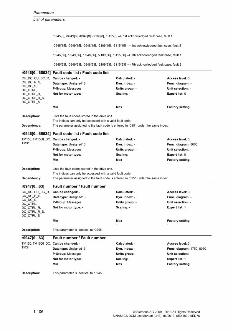
Parameters
List of parameters
1-106 © Siemens AG 2009 - 2013 All Rights ReservedSINAMICS DCM List Manual (LH8), 06/2013, 6RX1800-0ED76
r0945[8], r0949[8], r0948[8], r2109[8], r3115[8] --> 1st acknowledged fault case, fault 1
. . .
r0945[15], r0949[15], r0948[15], r2109[15], r3115[15] --> 1st acknowledged fault case, fault 8
. . .
r0945[56], r0949[56], r0948[56], r2109[56], r3115[56] --> 7th acknowledged fault case, fault 1
. . .
r0945[63], r0949[63], r0948[63], r2109[63], r3115[63] --> 7th acknowledged fault case, fault 8
Description: Lists the fault codes stored in the drive unit.
The indices can only be accessed with a valid fault code.
Dependency: The parameter assigned to the fault code is entered in r0951 under the same index.
Description: Lists the fault codes stored in the drive unit.
The indices can only be accessed with a valid fault code.
Dependency: The parameter assigned to the fault code is entered in r0951 under the same index.
Description: This parameter is identical to r0945.
Description: This parameter is identical to r0945.
r0946[0...65534] Fault code list / Fault code listCU_DC, CU_DC_R, CU_DC_R_S, CU_DC_S, DC_CTRL, DC_CTRL_R, DC_CTRL_R_S, DC_CTRL_S
Can be changed: - Calculated: - Access level: 3
Data type: Unsigned16 Dyn. index: - Func. diagram: -
P-Group: Messages Units group: - Unit selection: -
Not for motor type: - Scaling: - Expert list: 0
Min Max Factory setting - - -
r0946[0...65534] Fault code list / Fault code listTM150, TM15DI_DO, TM31
Can be changed: - Calculated: - Access level: 3
Data type: Unsigned16 Dyn. index: - Func. diagram: 8060
P-Group: Messages Units group: - Unit selection: -
Not for motor type: - Scaling: - Expert list: 0
Min Max Factory setting - - -
r0947[0...63] Fault number / Fault numberCU_DC, CU_DC_R, CU_DC_R_S, CU_DC_S, DC_CTRL, DC_CTRL_R, DC_CTRL_R_S, DC_CTRL_S
Can be changed: - Calculated: - Access level: 3
Data type: Unsigned16 Dyn. index: - Func. diagram: -
P-Group: Messages Units group: - Unit selection: -
Not for motor type: - Scaling: - Expert list: 1
Min Max Factory setting - - -
r0947[0...63] Fault number / Fault numberTM150, TM15DI_DO, TM31
Can be changed: - Calculated: - Access level: 3
Data type: Unsigned16 Dyn. index: - Func. diagram: 1750, 8060
P-Group: Messages Units group: - Unit selection: -
Not for motor type: - Scaling: - Expert list: 1
Min Max Factory setting - - -

List of parameters
Parameters
1-107© Siemens AG 2009 - 2013 All Rights ReservedSINAMICS DCM List Manual (LH8), 06/2013, 6RX1800-0ED76
Description: Displays the system runtime in milliseconds when the fault occurred.
Dependency: Refer to: r0945, r0947, r0949, r2109, r2114, r2130, r2133, r2136, r3115, r3120, r3122
Notice: The time comprises r2130 (days) and r0948 (milliseconds).
Note: The buffer parameters are cyclically updated in the background (refer to status signal in r2139).
The structure of the fault buffer and the assignment of the indices is shown in r0945.
When the parameter is read via PROFIdrive, the TimeDifference data type applies.
Description: Displays additional information about the fault that occurred (as integer number).
Dependency: Refer to: r0945, r0947, r0948, r2109, r2130, r2133, r2136, r3115, r3120, r3122
Note: The buffer parameters are cyclically updated in the background (refer to status signal in r2139).
The structure of the fault buffer and the assignment of the indices is shown in r0945.
Description: Displays additional information about the fault that occurred (as integer number).
r0948[0...63] Fault time received in milliseconds / t_fault recv msCU_DC, CU_DC_R, CU_DC_R_S, CU_DC_S, DC_CTRL, DC_CTRL_R, DC_CTRL_R_S, DC_CTRL_S
Can be changed: - Calculated: - Access level: 3
Data type: Unsigned32 Dyn. index: - Func. diagram: -
P-Group: Messages Units group: - Unit selection: -
Not for motor type: - Scaling: - Expert list: 1
Min Max Factory setting - [ms] - [ms] - [ms]
r0948[0...63] Fault time received in milliseconds / t_fault recv msTM150, TM15DI_DO, TM31
Can be changed: - Calculated: - Access level: 3
Data type: Unsigned32 Dyn. index: - Func. diagram: 1750, 8060
P-Group: Messages Units group: - Unit selection: -
Not for motor type: - Scaling: - Expert list: 1
Min Max Factory setting - [ms] - [ms] - [ms]
r0949[0...63] Fault value / Fault valueCU_DC, CU_DC_R, CU_DC_R_S, CU_DC_S, DC_CTRL, DC_CTRL_R, DC_CTRL_R_S, DC_CTRL_S
Can be changed: - Calculated: - Access level: 3
Data type: Integer32 Dyn. index: - Func. diagram: 8060
P-Group: Messages Units group: - Unit selection: -
Not for motor type: - Scaling: - Expert list: 1
Min Max Factory setting - - -
r0949[0...63] Fault value / Fault valueTM150, TM15DI_DO, TM31
Can be changed: - Calculated: - Access level: 3
Data type: Integer32 Dyn. index: - Func. diagram: 1750, 8060
P-Group: Messages Units group: - Unit selection: -
Not for motor type: - Scaling: - Expert list: 1
Min Max Factory setting - - -

Parameters
List of parameters
1-108 © Siemens AG 2009 - 2013 All Rights ReservedSINAMICS DCM List Manual (LH8), 06/2013, 6RX1800-0ED76
Dependency: Refer to: r0945, r0947, r0948, r2109, r2130, r2133, r2136, r3115, r3120, r3122
Note: The buffer parameters are cyclically updated in the background (refer to status signal in r2139).
The structure of the fault buffer and the assignment of the indices is shown in r0945.
Description: Number of fault situations that have occurred since the last reset.
Dependency: The fault buffer is deleted (cleared) by setting p0952 to 0.
Refer to: r0945, r0947, r0948, r0949, r2109, r2130, r2133, r2136
Description: Number of fault situations that have occurred since the last reset.
Dependency: The fault buffer is deleted (cleared) by setting p0952 to 0.
Refer to: r0945, r0947, r0948, r0949, r2109, r2130, r2133, r2136
Description: Displays the corresponding value for the PROFIBUS baud rate.
Value: 0: 9.6 kbit/s1: 19.2 kbit/s2: 93.75 kbit/s3: 187.5 kbit/s4: 500 kbit/s6: 1.5 Mbit/s7: 3 Mbit/s8: 6 Mbit/s9: 12 Mbit/s10: 31.25 kbit/s11: 45.45 kbit/s255: Unknown
p0952 Fault cases counter / Fault cases qtyCU_DC, CU_DC_R, CU_DC_R_S, CU_DC_S, DC_CTRL, DC_CTRL_R, DC_CTRL_R_S, DC_CTRL_S
Can be changed: U, T Calculated: - Access level: 3
Data type: Unsigned16 Dyn. index: - Func. diagram: 8060
P-Group: Messages Units group: - Unit selection: -
Not for motor type: - Scaling: - Expert list: 1
Min Max Factory setting 0 65535 0
p0952 Fault cases counter / Fault cases qtyTM150, TM15DI_DO, TM31
Can be changed: U, T Calculated: - Access level: 3
Data type: Unsigned16 Dyn. index: - Func. diagram: 1710, 8060
P-Group: Messages Units group: - Unit selection: -
Not for motor type: - Scaling: - Expert list: 1
Min Max Factory setting 0 65535 0
r0963 PROFIBUS baud rate / PB baud rateCU_DC, CU_DC_R, CU_DC_R_S, CU_DC_S
Can be changed: - Calculated: - Access level: 3
Data type: Unsigned16 Dyn. index: - Func. diagram: -
P-Group: Communications Units group: - Unit selection: -
Not for motor type: - Scaling: - Expert list: 1
Min Max Factory setting 0 255 -

List of parameters
Parameters
1-109© Siemens AG 2009 - 2013 All Rights ReservedSINAMICS DCM List Manual (LH8), 06/2013, 6RX1800-0ED76
Description: Displays the device identification.
Index: [0] = Company (Siemens = 42)[1] = Device type[2] = Firmware version[3] = Firmware date (year)[4] = Firmware date (day/month)[5] = Number of drive objects[6] = Firmware patch/hot fix
Note: Example:
r0964[0] = 42 --> SIEMENS
r0964[1] = 5490 --> SINAMICS DCM
r0964[2] = 102 --> first part of the firmware version V01.02 (second part, refer to index 6)
r0964[3] = 2010 --> year 2010
r0964[4] = 1401 --> 14th of January
r0964[5] = 4 --> 4 drive objects
r0964[6] = 600 --> second part, firmware version (complete version: V01.02.06.00)
Description: Displays the PROFIdrive profile number and profile version.
Constant value = 0329 hex.
Byte 1: Profile number = 03 hex = PROFIdrive profile
Byte 2: Profile version = 29 hex = Version 4.1
Note: When the parameter is read via PROFIdrive, the Octet String 2 data type applies.
Description: Displays the system runtime in ms since the last POWER ON.
Note: The value in p0969 can only be reset to 0.
The value overflows after approx. 49 days.
When the parameter is read via PROFIdrive, the TimeDifference data type applies.
r0964[0...6] Device identification / Device ident.CU_DC, CU_DC_R, CU_DC_R_S, CU_DC_S
Can be changed: - Calculated: - Access level: 2
Data type: Unsigned16 Dyn. index: - Func. diagram: -
P-Group: Communications Units group: - Unit selection: -
Not for motor type: - Scaling: - Expert list: 1
Min Max Factory setting - - -
r0965 PROFIdrive profile number / PD profile numberCU_DC, CU_DC_R, CU_DC_R_S, CU_DC_S
Can be changed: - Calculated: - Access level: 3
Data type: Unsigned16 Dyn. index: - Func. diagram: -
P-Group: Communications Units group: - Unit selection: -
Not for motor type: - Scaling: - Expert list: 1
Min Max Factory setting - - -
p0969 System runtime relative / t_System relativeCU_DC, CU_DC_R, CU_DC_R_S, CU_DC_S
Can be changed: T Calculated: - Access level: 3
Data type: Unsigned32 Dyn. index: - Func. diagram: 8060
P-Group: Displays, signals Units group: - Unit selection: -
Not for motor type: - Scaling: - Expert list: 1
Min Max Factory setting 0 [ms] 4294967295 [ms] 0 [ms]

Parameters
List of parameters
1-110 © Siemens AG 2009 - 2013 All Rights ReservedSINAMICS DCM List Manual (LH8), 06/2013, 6RX1800-0ED76
Description: The parameter is used to initiate a reset of the parameters on Terminal Module 150 (TM150).
Value: 0: Inactive1: Start a parameter reset100: Start a BICO interconnection reset
Dependency: Refer to: p0010
Notice: After the value has been modified, no further parameter modifications can be made and the status is shown in r3996. Modifications can be made again when r3996 = 0.
Note: A factory setting run can only be started if p0010 was first set to 30 (parameter reset).
At the end of the calculations, p0970 is automatically set to 0.
Description: The parameter is used to initiate a reset of the parameters on Terminal Module 15 (TM15).
The sampling time p4099 is not reset if in so doing a conflict occurs with the basic clock cycle.
Parameter p0151 is not reset. It is only reset if the entire drive unit is reset to the factory settings (p0976).
Value: 0: Inactive1: Start a parameter reset100: Start a BICO interconnection reset
Dependency: Refer to: p0010
Notice: After the value has been modified, no further parameter modifications can be made and the status is shown in r3996. Modifications can be made again when r3996 = 0.
Note: A factory setting run can only be started if p0010 was first set to 30 (parameter reset).
At the end of the calculations, p0970 is automatically set to 0.
Description: The parameter is used to initiate a reset of the parameters on Terminal Module 31 (TM31).
The sampling time p4099 is not reset if in so doing a conflict occurs with the basic clock cycle.
Parameter p0151 is not reset. It is only reset if the entire drive unit is reset to the factory settings (p0976).
Value: 0: Inactive1: Start a parameter reset100: Start a BICO interconnection reset
Dependency: Refer to: p0010
Notice: After the value has been modified, no further parameter modifications can be made and the status is shown in r3996. Modifications can be made again when r3996 = 0.
p0970 TM150 reset parameters / TM150 par resetTM150 Can be changed: C2(30) Calculated: - Access level: 2
Data type: Unsigned16 Dyn. index: - Func. diagram: -
P-Group: Factory settings Units group: - Unit selection: -
Not for motor type: - Scaling: - Expert list: 1
Min Max Factory setting 0 100 0
p0970 TM15DI/DO reset parameter / TM15D par resetTM15DI_DO Can be changed: C2(30) Calculated: - Access level: 2
Data type: Unsigned16 Dyn. index: - Func. diagram: -
P-Group: Factory settings Units group: - Unit selection: -
Not for motor type: - Scaling: - Expert list: 1
Min Max Factory setting 0 100 0
p0970 TM31 reset parameters / TM31 par resetTM31 Can be changed: C2(30) Calculated: - Access level: 2
Data type: Unsigned16 Dyn. index: - Func. diagram: -
P-Group: Factory settings Units group: - Unit selection: -
Not for motor type: - Scaling: - Expert list: 1
Min Max Factory setting 0 100 0
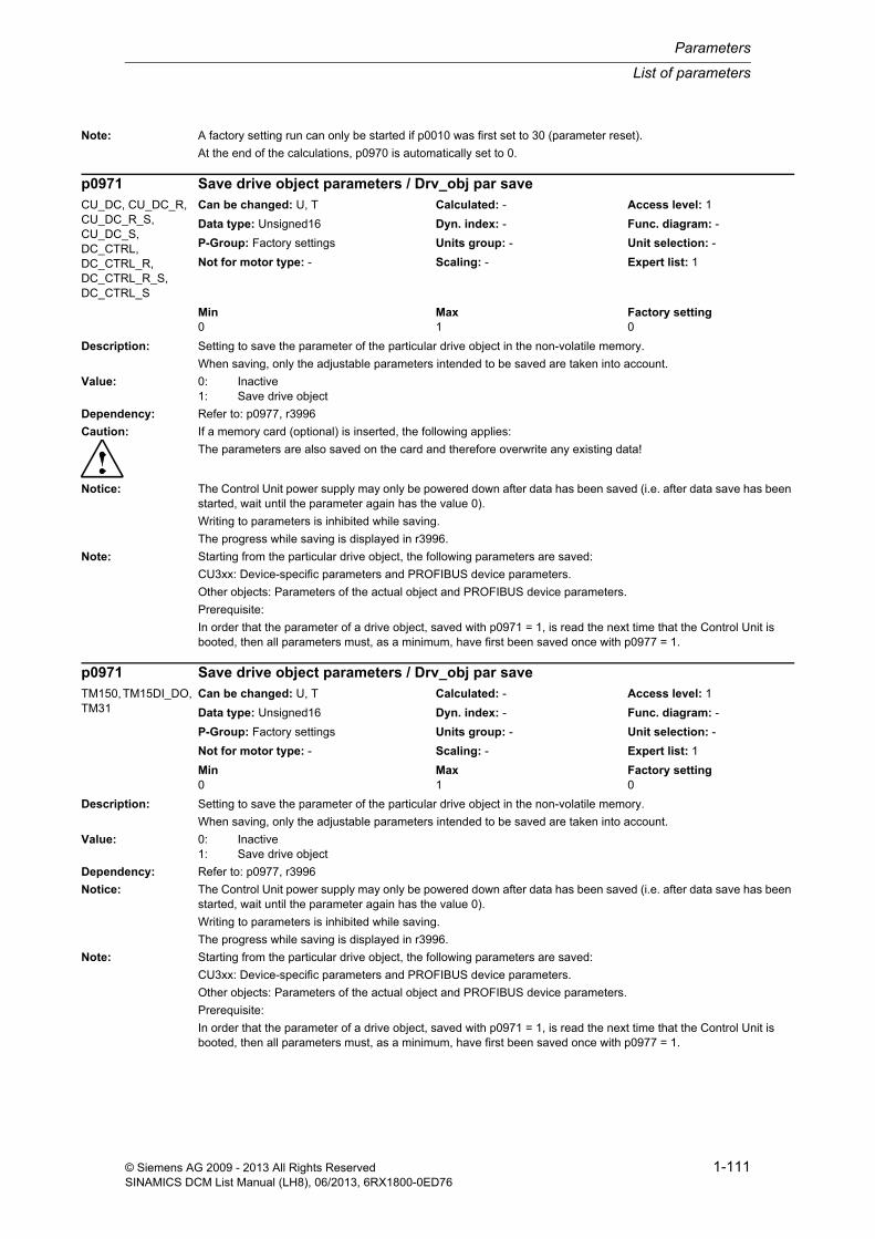
List of parameters
Parameters
1-111© Siemens AG 2009 - 2013 All Rights ReservedSINAMICS DCM List Manual (LH8), 06/2013, 6RX1800-0ED76
Note: A factory setting run can only be started if p0010 was first set to 30 (parameter reset).
At the end of the calculations, p0970 is automatically set to 0.
Description: Setting to save the parameter of the particular drive object in the non-volatile memory.
When saving, only the adjustable parameters intended to be saved are taken into account.
Value: 0: Inactive1: Save drive object
Dependency: Refer to: p0977, r3996
Caution: If a memory card (optional) is inserted, the following applies:
The parameters are also saved on the card and therefore overwrite any existing data!
Notice: The Control Unit power supply may only be powered down after data has been saved (i.e. after data save has been started, wait until the parameter again has the value 0).
Writing to parameters is inhibited while saving.
The progress while saving is displayed in r3996.
Note: Starting from the particular drive object, the following parameters are saved:
CU3xx: Device-specific parameters and PROFIBUS device parameters.
Other objects: Parameters of the actual object and PROFIBUS device parameters.
Prerequisite:
In order that the parameter of a drive object, saved with p0971 = 1, is read the next time that the Control Unit is booted, then all parameters must, as a minimum, have first been saved once with p0977 = 1.
Description: Setting to save the parameter of the particular drive object in the non-volatile memory.
When saving, only the adjustable parameters intended to be saved are taken into account.
Value: 0: Inactive1: Save drive object
Dependency: Refer to: p0977, r3996
Notice: The Control Unit power supply may only be powered down after data has been saved (i.e. after data save has been started, wait until the parameter again has the value 0).
Writing to parameters is inhibited while saving.
The progress while saving is displayed in r3996.
Note: Starting from the particular drive object, the following parameters are saved:
CU3xx: Device-specific parameters and PROFIBUS device parameters.
Other objects: Parameters of the actual object and PROFIBUS device parameters.
Prerequisite:
In order that the parameter of a drive object, saved with p0971 = 1, is read the next time that the Control Unit is booted, then all parameters must, as a minimum, have first been saved once with p0977 = 1.
p0971 Save drive object parameters / Drv_obj par saveCU_DC, CU_DC_R, CU_DC_R_S, CU_DC_S, DC_CTRL, DC_CTRL_R, DC_CTRL_R_S, DC_CTRL_S
Can be changed: U, T Calculated: - Access level: 1
Data type: Unsigned16 Dyn. index: - Func. diagram: -
P-Group: Factory settings Units group: - Unit selection: -
Not for motor type: - Scaling: - Expert list: 1
Min Max Factory setting 0 1 0
p0971 Save drive object parameters / Drv_obj par saveTM150, TM15DI_DO, TM31
Can be changed: U, T Calculated: - Access level: 1
Data type: Unsigned16 Dyn. index: - Func. diagram: -
P-Group: Factory settings Units group: - Unit selection: -
Not for motor type: - Scaling: - Expert list: 1
Min Max Factory setting 0 1 0
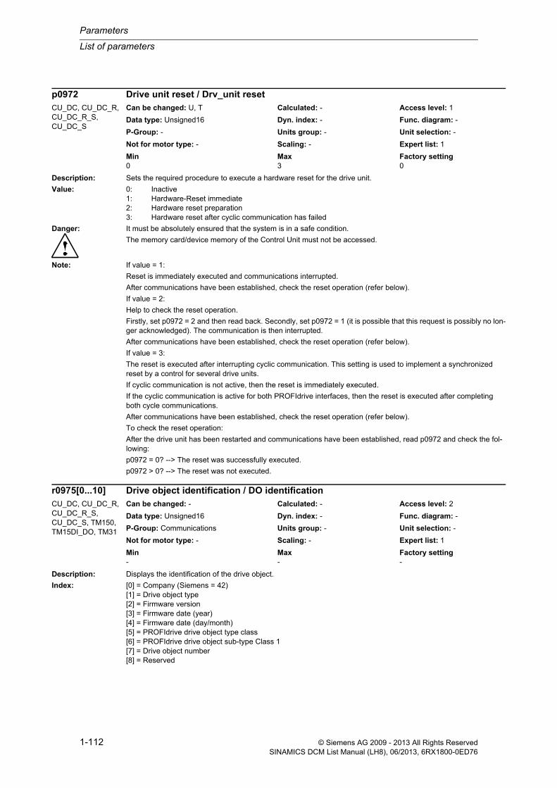
Parameters
List of parameters
1-112 © Siemens AG 2009 - 2013 All Rights ReservedSINAMICS DCM List Manual (LH8), 06/2013, 6RX1800-0ED76
Description: Sets the required procedure to execute a hardware reset for the drive unit.
Value: 0: Inactive1: Hardware-Reset immediate2: Hardware reset preparation3: Hardware reset after cyclic communication has failed
Danger: It must be absolutely ensured that the system is in a safe condition.
The memory card/device memory of the Control Unit must not be accessed.
Note: If value = 1:
Reset is immediately executed and communications interrupted.
After communications have been established, check the reset operation (refer below).
If value = 2:
Help to check the reset operation.
Firstly, set p0972 = 2 and then read back. Secondly, set p0972 = 1 (it is possible that this request is possibly no lon-ger acknowledged). The communication is then interrupted.
After communications have been established, check the reset operation (refer below).
If value = 3:
The reset is executed after interrupting cyclic communication. This setting is used to implement a synchronized reset by a control for several drive units.
If cyclic communication is not active, then the reset is immediately executed.
If the cyclic communication is active for both PROFIdrive interfaces, then the reset is executed after completing both cycle communications.
After communications have been established, check the reset operation (refer below).
To check the reset operation:
After the drive unit has been restarted and communications have been established, read p0972 and check the fol-lowing:
p0972 = 0? --> The reset was successfully executed.
p0972 > 0? --> The reset was not executed.
Description: Displays the identification of the drive object.
Index: [0] = Company (Siemens = 42)[1] = Drive object type[2] = Firmware version[3] = Firmware date (year)[4] = Firmware date (day/month)[5] = PROFIdrive drive object type class[6] = PROFIdrive drive object sub-type Class 1[7] = Drive object number[8] = Reserved
p0972 Drive unit reset / Drv_unit resetCU_DC, CU_DC_R, CU_DC_R_S, CU_DC_S
Can be changed: U, T Calculated: - Access level: 1
Data type: Unsigned16 Dyn. index: - Func. diagram: -
P-Group: - Units group: - Unit selection: -
Not for motor type: - Scaling: - Expert list: 1
Min Max Factory setting 0 3 0
r0975[0...10] Drive object identification / DO identificationCU_DC, CU_DC_R, CU_DC_R_S, CU_DC_S, TM150, TM15DI_DO, TM31
Can be changed: - Calculated: - Access level: 2
Data type: Unsigned16 Dyn. index: - Func. diagram: -
P-Group: Communications Units group: - Unit selection: -
Not for motor type: - Scaling: - Expert list: 1
Min Max Factory setting - - -

List of parameters
Parameters
1-113© Siemens AG 2009 - 2013 All Rights ReservedSINAMICS DCM List Manual (LH8), 06/2013, 6RX1800-0ED76
[9] = Reserved[10] = Firmware patch/hot fix
Note: Example:
r0975[0] = 42 --> SIEMENS
r0975[1] = 11 --> SERVO drive object type
r0975[2] = 102 --> first part, firmware version V01.02 (second part, refer to index 10)
r0975[3] = 2003 --> year 2003
r0975[4] = 1401 --> 14th of January
r0975[5] = 1 --> PROFIdrive drive object, type class
r0975[6] = 9 --> PROFIdrive drive object sub-type class 1
r0975[7] = 2 --> drive object number = 2
r0975[8] = 0 (reserved)
r0975[9] = 0 (reserved)
r0975[10] = 600 --> second part, firmware version (complete version: V01.02.06.00)
Description: Displays the identification of the drive object.
Index: [0] = Company (Siemens = 42)[1] = Drive object type[2] = Firmware version[3] = Firmware date (year)[4] = Firmware date (day/month)[5] = PROFIdrive drive object type class[6] = PROFIdrive drive object sub-type Class 1[7] = Drive object number[8] = Reserved[9] = Reserved[10] = Firmware patch/hot fix
Note: Example:
r0975[0] = 42 --> SIEMENS
r0975[1] = 17 --> DC_CTRL drive object type
r0975[2] = 102 --> first part, firmware version V01.02 (second part, refer to index 10)
r0975[3] = 2003 --> year 2003
r0975[4] = 1401 --> 14th of January
r0975[5] = 1 --> PROFIdrive drive object, type class
r0975[6] = 9 --> PROFIdrive drive object sub-type class 1
r0975[7] = 2 --> drive object number = 2
r0975[8] = 0 (reserved)
r0975[9] = 0 (reserved)
r0975[10] = 600 --> second part, firmware version (complete version: V01.02.06.00)
Description: Resets or downloads all parameters of the drive system.
r0975[0...10] Drive object identification / DO identificationDC_CTRL, DC_CTRL_R, DC_CTRL_R_S, DC_CTRL_S
Can be changed: - Calculated: - Access level: 2
Data type: Unsigned16 Dyn. index: - Func. diagram: -
P-Group: Communications Units group: - Unit selection: -
Not for motor type: - Scaling: - Expert list: 1
Min Max Factory setting - - -
p0976 Reset and load all parameters / Reset load all parCU_DC, CU_DC_R, CU_DC_R_S, CU_DC_S
Can be changed: C1(30) Calculated: - Access level: 1
Data type: Unsigned16 Dyn. index: - Func. diagram: -
P-Group: Factory settings Units group: - Unit selection: -
Not for motor type: - Scaling: - Expert list: 1
Min Max Factory setting 0 1013 0

Parameters
List of parameters
1-114 © Siemens AG 2009 - 2013 All Rights ReservedSINAMICS DCM List Manual (LH8), 06/2013, 6RX1800-0ED76
Value: 0: Inactive1: Start reset of all parameters to factory setting2: Start dnload of param. saved in non-volatile mem w/ p0977=13: Start download of volatile parameters from RAM10: Start dnload of param. saved in non-volatile mem w/ p0977=1011: Start dnload of param. saved in non-volatile mem w/ p0977=1112: Start dnload of param. saved in non-volatile mem w/ p0977=1220: Start download Siemens internal setting 20100: Start resetting of all BICO interconnections200: Start deleting all user data1011: Start dnload of param. saved in volatile mem w/ p0977=10111012: Start dnload of param. saved in volatile mem w/ p0977=10121013: Start dnload of param. saved in volatile mem w/ p0977=1013
Notice: After the value has been modified, no further parameter modifications can be made and the status is shown in r3996. Modifications can be made again when r3996 = 0.
After executing p0976 = 200, the Control Unit is powered on automatically.
Note: After all of the parameters have been reset to their factory setting, the system must be commissioned for the first time again.
Resetting or loading is realized in the non-volatile memory.
Procedure:
1. Set p0009 = 30 (parameter reset).
2. Set p0976 to "required value". The system is rebooted.
p0976 is automatically set to 0 after execution.
Description: Saves all parameters of the drive system to the non-volatile memory.
When saving, only the adjustable parameters intended to be saved are taken into account.
Value: 0: Inactive1: Save in non-volatile memory - downloaded at POWER ON10: Save as opt. in non-vol. memory - downloaded w/ p0976=1011: Save as opt. in non-vol. memory - downloaded w/ p0976=1112: Save as opt. in non-vol. memory - downloaded w/ p0976=1220: Save in non-volatile memory as setting 20 (reserved)80: Save in non-volatile memory time-optimized (reserved)1011: Save in volatile memory, downloaded with p0976=10111012: Save in volatile memory, downloaded with p0976=10121013: Save in volatile memory, downloaded with p0976=1013
Dependency: Refer to: p0976, r3996
Caution: Memory card inserted:
The drive parameterization is also saved on the card. Any backed-up data is overwritten!
Notice: The Control Unit power supply may only be powered down after data has been saved (i.e. after data save has been started, wait until the parameter again has the value 0).
Writing to parameters is inhibited while saving.
The progress while saving is displayed in r3996.
Note: Parameters saved with p0977 = 10, 11 or 12 can be downloaded again with p0976 = 10, 11 or 12.
p0977 Save all parameters / Save all parCU_DC, CU_DC_R, CU_DC_R_S, CU_DC_S
Can be changed: U, T Calculated: - Access level: 1
Data type: Unsigned16 Dyn. index: - Func. diagram: -
P-Group: Factory settings Units group: - Unit selection: -
Not for motor type: - Scaling: - Expert list: 1
Min Max Factory setting 0 1013 0

List of parameters
Parameters
1-115© Siemens AG 2009 - 2013 All Rights ReservedSINAMICS DCM List Manual (LH8), 06/2013, 6RX1800-0ED76
Description: This parameter is an image of p0101 in conformance with PROFIdrive.
Parameters p0101 and p0978 contain the following information:
1) The same number of drive objects
2) The same drive objects
In this sense, they are consistent.
Difference between p0101 and p0978:
p0978 can be re-sorted and a zero inserted in order to identify those drive objects that participate in the process data exchange and to define their sequence in the process data exchange. Drive objects that are listed after the first zero, are excluded from the process data exchange.
For p0978, in addition, the value 255 can be inserted a multiple number of times.
p0978[n] = 255 means: The drive object is visible for the PROFIBUS master and is empty (without any actual pro-cess data exchange). This allows cyclic communications of a PROFIBUS master with unchanged configuring to the drive units with a lower number of drive objects.
Dependency: Refer to: p0101, p0971, p0977
Note: p0978 cannot be changed when the drive system is first commissioned. The reason for this is that at this time the actual topology has still not been acknowledged (p0099 is still not equal to r0098 and p0009 is set to 0).
Description: Displays the actual position encoder used according to PROFIdrive.
Index: [0] = Header[1] = Type encoder 1[2] = Resolution enc 1[3] = Shift factor G1_XIST1[4] = Shift factor G1_XIST2[5] = Distinguishable revolutions encoder 1[6...10] = Reserved[11] = Type encoder 2[12] = Resolution enc 2[13] = Shift factor G2_XIST1[14] = Shift factor G2_XIST2[15] = Distinguishable revolutions encoder 2[16...20] = Reserved[21] = Type encoder 3[22] = Resolution enc 3[23] = Shift factor G3_XIST1[24] = Shift factor G3_XIST2[25] = Distinguishable revolutions encoder 3[26...30] = Reserved
Note: Information about the individual indices can be taken from the following literature:
PROFIdrive Profile Drive Technology
p0978[0...24] List of drive objects / List of the DOCU_DC, CU_DC_R, CU_DC_R_S, CU_DC_S
Can be changed: C1(1) Calculated: - Access level: 2
Data type: Unsigned8 Dyn. index: - Func. diagram: -
P-Group: Topology Units group: - Unit selection: -
Not for motor type: - Scaling: - Expert list: 1
Min Max Factory setting 0 255 [0] 1
[1...24] 0
r0979[0...30] PROFIdrive encoder format / PD encoder formatDC_CTRL, DC_CTRL_R, DC_CTRL_R_S, DC_CTRL_S
Can be changed: - Calculated: - Access level: 3
Data type: Unsigned32 Dyn. index: - Func. diagram: 4704
P-Group: Encoder Units group: - Unit selection: -
Not for motor type: - Scaling: - Expert list: 1
Min Max Factory setting - - -

Parameters
List of parameters
1-116 © Siemens AG 2009 - 2013 All Rights ReservedSINAMICS DCM List Manual (LH8), 06/2013, 6RX1800-0ED76
Description: Displays the parameters that exist for this drive.
Dependency: Refer to: r0981, r0989
Note: The existing parameters are displayed in indices 0 to 298. If an index contains the value 0, then the list ends here. In a long list, index 299 contains the parameter number at which position the list continues.
This list consists solely of the following parameters:
r0980[0...299], r0981[0...299] ... r0989[0...299]
The parameters in this list are not displayed in the expert list of the commissioning software. However, they can be read from a higher-level control system (e.g. PROFIBUS master).
Description: Displays the parameters that exist for this drive.
Dependency: Refer to: r0980, r0989
Note: The existing parameters are displayed in indices 0 to 298. If an index contains the value 0, then the list ends here. In a long list, index 299 contains the parameter number at which position the list continues.
This list consists solely of the following parameters:
r0980[0...299], r0981[0...299] ... r0989[0...299]
The parameters in this list are not displayed in the expert list of the commissioning software. However, they can be read from a higher-level control system (e.g. PROFIBUS master).
Description: Displays the parameters that exist for this drive.
Dependency: Refer to: r0980, r0981
Note: The existing parameters are displayed in indices 0 to 298. If an index contains the value 0, then the list ends here.
This list consists solely of the following parameters:
r0980[0...299], r0981[0...299] ... r0989[0...299]
The parameters in this list are not displayed in the expert list of the commissioning software. However, they can be read from a higher-level control system (e.g. PROFIBUS master).
r0980[0...299] List of existing parameters 1 / List avail par 1All objects Can be changed: - Calculated: - Access level: 4
Data type: Unsigned16 Dyn. index: - Func. diagram: -
P-Group: - Units group: - Unit selection: -
Not for motor type: - Scaling: - Expert list: 0
Min Max Factory setting - - -
r0981[0...299] List of existing parameters 2 / List avail par 2All objects Can be changed: - Calculated: - Access level: 4
Data type: Unsigned16 Dyn. index: - Func. diagram: -
P-Group: - Units group: - Unit selection: -
Not for motor type: - Scaling: - Expert list: 0
Min Max Factory setting - - -
r0989[0...299] List of existing parameters 10 / List avail par 10All objects Can be changed: - Calculated: - Access level: 4
Data type: Unsigned16 Dyn. index: - Func. diagram: -
P-Group: - Units group: - Unit selection: -
Not for motor type: - Scaling: - Expert list: 0
Min Max Factory setting - - -

List of parameters
Parameters
1-117© Siemens AG 2009 - 2013 All Rights ReservedSINAMICS DCM List Manual (LH8), 06/2013, 6RX1800-0ED76
Description: Displays those parameters with a value other than the factory setting for this drive.
Dependency: Refer to: r0991, r0999
Note: Modified parameters are displayed in indices 0 to 98. If an index contains the value 0, then the list ends here. In a long list, index 99 contains the parameter number at which position the list continues.
This list consists solely of the following parameters:
r0990[0...99], r0991[0...99] ... r0999[0...99]
The parameters in this list are not displayed in the expert list of the commissioning software. However, they can be read from a higher-level control system (e.g. PROFIBUS master).
Description: Displays those parameters with a value other than the factory setting for this drive.
Dependency: Refer to: r0990, r0999
Note: Modified parameters are displayed in indices 0 to 98. If an index contains the value 0, then the list ends here. In a long list, index 99 contains the parameter number at which position the list continues.
This list consists solely of the following parameters:
r0990[0...99], r0991[0...99] ... r0999[0...99]
The parameters in this list are not displayed in the expert list of the commissioning software. However, they can be read from a higher-level control system (e.g. PROFIBUS master).
Description: Displays those parameters with a value other than the factory setting for this drive.
Dependency: Refer to: r0990, r0991
Note: Modified parameters are displayed in indices 0 to 98. If an index contains the value 0, then the list ends here.
This list consists solely of the following parameters:
r0990[0...99], r0991[0...99] ... r0999[0...99]
The parameters in this list are not displayed in the expert list of the commissioning software. However, they can be read from a higher-level control system (e.g. PROFIBUS master).
r0990[0...99] List of modified parameters 1 / List chang. par 1All objects Can be changed: - Calculated: - Access level: 3
Data type: Unsigned16 Dyn. index: - Func. diagram: -
P-Group: - Units group: - Unit selection: -
Not for motor type: - Scaling: - Expert list: 0
Min Max Factory setting - - -
r0991[0...99] List of modified parameters 2 / List chang. par 2All objects Can be changed: - Calculated: - Access level: 3
Data type: Unsigned16 Dyn. index: - Func. diagram: -
P-Group: - Units group: - Unit selection: -
Not for motor type: - Scaling: - Expert list: 0
Min Max Factory setting - - -
r0999[0...99] List of modified parameters 10 / List chang. par 10All objects Can be changed: - Calculated: - Access level: 3
Data type: Unsigned16 Dyn. index: - Func. diagram: -
P-Group: - Units group: - Unit selection: -
Not for motor type: - Scaling: - Expert list: 0
Min Max Factory setting - - -

Parameters
List of parameters
1-118 © Siemens AG 2009 - 2013 All Rights ReservedSINAMICS DCM List Manual (LH8), 06/2013, 6RX1800-0ED76
Description: Runs the corresponding macro files.
The Connector Inputs (CI) for the speed setpoints of the appropriate Command Data Set (CDS) are appropriately interconnected.
The selected macro file must be available on the memory card/device memory.
Example:
p1000 = 6 --> the macro file PM000006.ACX is run.
Dependency: Refer to: p0015, p0700, p1500, r8572
Caution: When executing a specific macro, the corresponding programmed settings are made and become active.
Notice: No errors were issued during quick commissioning (p3900 = 1) when writing to parameters of the QUICK_IBN group!
Note: The macros in the specified directory are displayed in r8572. r8572 is not in the expert list of the commissioning software.
Macros available as standard are described in the technical documentation of the particular product.
CI: Connector Input
Description: Sets the signal source to continually increase the setpoint for the motorized potentiometer.
The setpoint change (CO: r1050) depends on the set ramp-up time (p1047) and the duration of the signal that is present (BI: p1035).
Dependency: Refer to: p1036
Notice: The parameter may be protected as a result of p0922 or p2079 and cannot be changed.
Description: Sets the signal source to continuously lower the setpoint for the motorized potentiometer.
The setpoint change (CO: r1050) depends on the set ramp-down time (p1048) and the duration of the signal that is present (BI: p1036).
Dependency: Refer to: p1035
Notice: The parameter may be protected as a result of p0922 or p2079 and cannot be changed.
p1000[0...n] Macro Connector Inputs (CI) for speed setpoints / Macro CI n_setDC_CTRL, DC_CTRL_R, DC_CTRL_R_S, DC_CTRL_S
Can be changed: C2(1), T Calculated: - Access level: 1
Data type: Unsigned32 Dyn. index: CDS, p0170 Func. diagram: -
P-Group: Commands Units group: - Unit selection: -
Not for motor type: - Scaling: - Expert list: 1
Min Max Factory setting 0 999999 0
p1035[0...n] BI: Motorized potentiometer setpoint raise / Mop raiseDC_CTRL, DC_CTRL_R, DC_CTRL_R_S, DC_CTRL_S
Can be changed: T Calculated: - Access level: 3
Data type: Unsigned32 / Binary Dyn. index: CDS, p0170 Func. diagram: -
P-Group: Setpoints Units group: - Unit selection: -
Not for motor type: - Scaling: - Expert list: 1
Min Max Factory setting - - 0
p1036[0...n] BI: Motorized potentiometer lower setpoint / Mop lowerDC_CTRL, DC_CTRL_R, DC_CTRL_R_S, DC_CTRL_S
Can be changed: T Calculated: - Access level: 3
Data type: Unsigned32 / Binary Dyn. index: CDS, p0170 Func. diagram: -
P-Group: Setpoints Units group: - Unit selection: -
Not for motor type: - Scaling: - Expert list: 1
Min Max Factory setting - - 0

List of parameters
Parameters
1-119© Siemens AG 2009 - 2013 All Rights ReservedSINAMICS DCM List Manual (LH8), 06/2013, 6RX1800-0ED76
Description: Sets the signal source for jog 1.
Recommend.: When the setting for this binector input is changed, the motor can only be switched on by means of an appropriate signal change of the source.
Dependency: Refer to: p0840
Notice: The drive is enabled for jogging using BI: p1055 or BI: p1056.
The command "ON/OFF1" can be issued using BI: p0840 or using BI: p1055/p1056.
Only the signal source that was used to power up can also be used to power down again.
Description: Sets the signal source for jog 2.
Recommend.: When the setting for this binector input is changed, the motor can only be switched on by means of an appropriate signal change of the source.
Dependency: Refer to: p0840
Notice: The drive is enabled for jogging using BI: p1055 or BI: p1056.
The command "ON/OFF1" can be issued using BI: p0840 or using BI: p1055/p1056.
Only the signal source that was used to power up can also be used to power down again.
Description: Sets the signal source for the main setpoint.
Notice: The parameter may be protected as a result of p0922 or p2079 and cannot be changed.
Description: Sets the signal source to invert the setpoint.
Notice: The parameter may be protected as a result of p0922 or p2079 and cannot be changed.
p1055[0...n] BI: Jog bit 0 / Jog bit 0DC_CTRL, DC_CTRL_R, DC_CTRL_R_S, DC_CTRL_S
Can be changed: T Calculated: - Access level: 3
Data type: Unsigned32 / Binary Dyn. index: CDS, p0170 Func. diagram: 2580
P-Group: Setpoints Units group: - Unit selection: -
Not for motor type: - Scaling: - Expert list: 1
Min Max Factory setting - - 0
p1056[0...n] BI: Jog bit 1 / Jog bit 1DC_CTRL, DC_CTRL_R, DC_CTRL_R_S, DC_CTRL_S
Can be changed: T Calculated: - Access level: 3
Data type: Unsigned32 / Binary Dyn. index: CDS, p0170 Func. diagram: 2580
P-Group: Setpoints Units group: - Unit selection: -
Not for motor type: - Scaling: - Expert list: 1
Min Max Factory setting - - 0
p1070[0...n] CI: Main setpoint / Main setpointDC_CTRL, DC_CTRL_R, DC_CTRL_R_S, DC_CTRL_S
Can be changed: T Calculated: - Access level: 3
Data type: Unsigned32 / FloatingPoint32 Dyn. index: CDS, p0170 Func. diagram: 3113
P-Group: Setpoints Units group: - Unit selection: -
Not for motor type: - Scaling: p2000 Expert list: 1
Min Max Factory setting - - 0
p1113[0...n] BI: Setpoint inversion / Setp invDC_CTRL, DC_CTRL_R, DC_CTRL_R_S, DC_CTRL_S
Can be changed: T Calculated: - Access level: 3
Data type: Unsigned32 / Binary Dyn. index: CDS, p0170 Func. diagram: 2442, 3113
P-Group: Setpoints Units group: - Unit selection: -
Not for motor type: - Scaling: - Expert list: 1
Min Max Factory setting - - 0

Parameters
List of parameters
1-120 © Siemens AG 2009 - 2013 All Rights ReservedSINAMICS DCM List Manual (LH8), 06/2013, 6RX1800-0ED76
Description: Sets the signal source for the command "enable ramp-function generator/inhibit ramp-function generator".
For the PROFIdrive profile, this command corresponds to control word 1 bit 4 (STW1.4).
BI: p1140 = 0 signal:
Inhibits the ramp-function generator (the ramp-function generator output is set to zero).
BI: p1140 = 1 signal:
Ramp-function generator enable.
Dependency: Refer to: p1141, p1142
Caution: When "master control from PC" is activated, this binector input is ineffective.
Notice: The parameter may be protected as a result of p0922 or p2079 and cannot be changed.
Description: Sets the signal source for the command "continue ramp-function generator/freeze ramp-function generator".
For the PROFIdrive profile, this command corresponds to control word 1 bit 5 (STW1.5).
BI: p1141 = 0 signal:
Freezes the ramp-function generator.
BI: p1141 = 1 signal:
Continue ramp-function generator.
Dependency: Refer to: p1140, p1142
Caution: When "master control from PC" is activated, this binector input is ineffective.
Description: Sets the signal source for the command "enable setpoint/inhibit setpoint".
For the PROFIdrive profile, this command corresponds to control word 1 bit 6 (STW1.6).
BI: p1142 = 0 signal
Inhibits the setpoint (the ramp-function generator input is set to zero).
BI: p1142 = 1 signal
Setpoint enable.
Dependency: Refer to: p1140, p1141
p1140[0...n] BI: Enable ramp-function generator/inhibit ramp-function generator / RFG enableDC_CTRL, DC_CTRL_R, DC_CTRL_R_S, DC_CTRL_S
Can be changed: T Calculated: - Access level: 3
Data type: Unsigned32 / Binary Dyn. index: CDS, p0170 Func. diagram: 2580
P-Group: Setpoints Units group: - Unit selection: -
Not for motor type: - Scaling: - Expert list: 1
Min Max Factory setting - - 1
p1141[0...n] BI: Continue ramp-function generator/freeze ramp-function generator / Continue RFGDC_CTRL, DC_CTRL_R, DC_CTRL_R_S, DC_CTRL_S
Can be changed: T Calculated: - Access level: 3
Data type: Unsigned32 / Binary Dyn. index: CDS, p0170 Func. diagram: 2580
P-Group: Setpoints Units group: - Unit selection: -
Not for motor type: - Scaling: - Expert list: 1
Min Max Factory setting - - 1
p1142[0...n] BI: Enable setpoint/inhibit setpoint / Setpoint enableDC_CTRL, DC_CTRL_R, DC_CTRL_R_S, DC_CTRL_S
Can be changed: T Calculated: - Access level: 3
Data type: Unsigned32 / Binary Dyn. index: CDS, p0170 Func. diagram: 2580
P-Group: Setpoints Units group: - Unit selection: -
Not for motor type: - Scaling: - Expert list: 1
Min Max Factory setting - - 1

List of parameters
Parameters
1-121© Siemens AG 2009 - 2013 All Rights ReservedSINAMICS DCM List Manual (LH8), 06/2013, 6RX1800-0ED76
Caution: When "master control from PC" is activated, this binector input is ineffective.
Notice: The parameter may be protected as a result of p0922 or p2079 and cannot be changed.
Note: When the function module "position control" (r0108.3 = 1) is activated, this binector input is interconnected as fol-lows as standard:
BI: p1142 = 0 signal
Description: Displays the status word of the speed controller.
Description: Sets the smoothing time constant (PT1) for the speed actual value.
Dependency: Refer to: r0063
Note: The speed actual value should be smoothed for encoders with a low pulse number or for resolvers.
After this parameter has been changed, we recommend that the speed controller is adjusted and/or the speed con-troller settings Kp (r50219) and Tn (r50218) checked.
r1407.0...15 CO/BO: Status word speed controller / ZSW n_ctrlDC_CTRL, DC_CTRL_R, DC_CTRL_R_S, DC_CTRL_S
Can be changed: - Calculated: - Access level: 3
Data type: Unsigned32 Dyn. index: - Func. diagram: -
P-Group: Closed-loop control Units group: - Unit selection: -
Not for motor type: REL Scaling: - Expert list: 1
Min Max Factory setting - - -
Bit field: Bit Signal name 1 signal 0 signal FP00 U/f control active Yes No -01 Encoderless operation active Yes No -02 Torque control active Yes No 6030,
6060, 8010
03 Speed control active Yes No 604005 Speed controller I component frozen Yes No 604006 Speed controller I component set Yes No 604007 Torque limit reached Yes No 606008 Upper torque limit active Yes No 606009 Lower torque limit active Yes No 606010 Droop enabled Yes No 603011 Speed setpoint limited Yes No 603012 Ramp-function generator set Yes No -13 Encoderless operation due to a fault Yes No -14 I/f control active Yes No -15 Torque limit reached (without pre-control) Yes No 6060
p1441[0...n] Actual speed smoothing time / n_act T_smoothDC_CTRL, DC_CTRL_R, DC_CTRL_R_S, DC_CTRL_S
Can be changed: U, T Calculated: CALC_MOD_CON Access level: 3
Data type: FloatingPoint32 Dyn. index: DDS, p0180 Func. diagram: 4711
P-Group: Closed-loop control Units group: - Unit selection: -
Not for motor type: REL Scaling: - Expert list: 1
Min Max Factory setting 0.00 [ms] 50.00 [ms] 0.00 [ms]

Parameters
List of parameters
1-122 © Siemens AG 2009 - 2013 All Rights ReservedSINAMICS DCM List Manual (LH8), 06/2013, 6RX1800-0ED76
Description: Runs the corresponding macro files.
The Connector Inputs (CI) for the torque setpoints of the appropriate Command Data Set (CDS) are appropriately interconnected.
The selected macro file must be available on the memory card/device memory.
Example:
p1500 = 6 --> the macro file PM000006.ACX is run.
Dependency: Refer to: p0015, p0700, p1000, r8573
Caution: When executing a specific macro, the corresponding programmed settings are made and become active.
Notice: No errors were issued during quick commissioning (p3900 = 1) when writing to parameters of the QUICK_IBN group!
Note: The macros in the specified directory are displayed in r8573. r8573 is not in the expert list of the commissioning software.
Macros available as standard are described in the technical documentation of the particular product.
CI: Connector Input
Description: Setting to change the direction of rotation.
Changing the parameter reverses the direction of the encoder actual value.
Value: 0: CW1: CCW
Caution: Changing the direction using p1820 or p1821 is not recognized by the "Safe Direction without encoder". As a con-sequence, the limit provided by SDI (Safe Direction) from r9733 no longer functions.
Notice: An appropriate fault is output for a drive data set changeover where the direction of rotation changes and the pulses are enabled.
Description: Sets the reference quantity for speed.
The reference quantity corresponds to 100% or 4000 hex (word) or 4000 0000 hex (double word).
Dependency: Refer to: p2001, p2002, p2003, r2004
p1500[0...n] Macro Connector Inputs (CI) for torque setpoints / Macro CI M_setDC_CTRL, DC_CTRL_R, DC_CTRL_R_S, DC_CTRL_S
Can be changed: C2(1), T Calculated: - Access level: 1
Data type: Unsigned32 Dyn. index: CDS, p0170 Func. diagram: -
P-Group: Commands Units group: - Unit selection: -
Not for motor type: REL Scaling: - Expert list: 1
Min Max Factory setting 0 999999 0
p1821[0...n] Direction of rotation / Dir of rotDC_CTRL, DC_CTRL_R, DC_CTRL_R_S, DC_CTRL_S
Can be changed: C2(1, 4) Calculated: - Access level: 3
Data type: Integer16 Dyn. index: DDS, p0180 Func. diagram: 4704, 4710, 4711
P-Group: Encoder Units group: - Unit selection: -
Not for motor type: - Scaling: - Expert list: 1
Min Max Factory setting 0 1 0
p2000 Reference speed / n_refDC_CTRL, DC_CTRL_R, DC_CTRL_R_S, DC_CTRL_S
Can be changed: T Calculated: CALC_MOD_ALL Access level: 2
Data type: FloatingPoint32 Dyn. index: - Func. diagram: 3113, 9566, 9568, 9572
P-Group: Communications Units group: - Unit selection: -
Not for motor type: - Scaling: - Expert list: 1
Min Max Factory setting 6.00 [rpm] 210000.00 [rpm] 210000.00 [rpm]
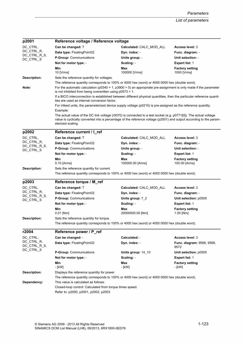
List of parameters
Parameters
1-123© Siemens AG 2009 - 2013 All Rights ReservedSINAMICS DCM List Manual (LH8), 06/2013, 6RX1800-0ED76
Description: Sets the reference quantity for voltages.
The reference quantity corresponds to 100% or 4000 hex (word) or 4000 0000 hex (double word).
Note: For the automatic calculation (p0340 = 1, p3900 > 0) an appropriate pre-assignment is only made if the parameter is not inhibited from being overwritten using p0573 = 1.
If a BICO interconnection is established between different physical quantities, then the particular reference quanti-ties are used as internal conversion factor.
For infeed units, the parameterized device supply voltage (p0210) is pre-assigned as the reference quantity.
Example:
The actual value of the DC link voltage (r0070) is connected to a test socket (e.g. p0771[0]). The actual voltage value is cyclically converted into a percentage of the reference voltage (p2001) and output according to the param-eterized scaling.
Description: Sets the reference quantity for current.
The reference quantity corresponds to 100% or 4000 hex (word) or 4000 0000 hex (double word).
Description: Sets the reference quantity for torque.
The reference quantity corresponds to 100% or 4000 hex (word) or 4000 0000 hex (double word).
Description: Displays the reference quantity for power.
The reference quantity corresponds to 100% or 4000 hex (word) or 4000 0000 hex (double word).
Dependency: This value is calculated as follows:
Closed-loop control: Calculated from torque times speed.
Refer to: p2000, p2001, p2002, p2003
p2001 Reference voltage / Reference voltageDC_CTRL, DC_CTRL_R, DC_CTRL_R_S, DC_CTRL_S
Can be changed: T Calculated: CALC_MOD_ALL Access level: 3
Data type: FloatingPoint32 Dyn. index: - Func. diagram: -
P-Group: Communications Units group: - Unit selection: -
Not for motor type: - Scaling: - Expert list: 1
Min Max Factory setting 10 [Vrms] 100000 [Vrms] 1000 [Vrms]
p2002 Reference current / I_refDC_CTRL, DC_CTRL_R, DC_CTRL_R_S, DC_CTRL_S
Can be changed: T Calculated: CALC_MOD_ALL Access level: 3
Data type: FloatingPoint32 Dyn. index: - Func. diagram: -
P-Group: Communications Units group: - Unit selection: -
Not for motor type: - Scaling: - Expert list: 1
Min Max Factory setting 0.10 [Arms] 100000.00 [Arms] 100.00 [Arms]
p2003 Reference torque / M_refDC_CTRL, DC_CTRL_R, DC_CTRL_R_S, DC_CTRL_S
Can be changed: T Calculated: CALC_MOD_ALL Access level: 3
Data type: FloatingPoint32 Dyn. index: - Func. diagram: -
P-Group: Communications Units group: 7_2 Unit selection: p0505
Not for motor type: - Scaling: - Expert list: 1
Min Max Factory setting 0.01 [Nm] 20000000.00 [Nm] 1.00 [Nm]
r2004 Reference power / P_refDC_CTRL, DC_CTRL_R, DC_CTRL_R_S, DC_CTRL_S
Can be changed: - Calculated: - Access level: 3
Data type: FloatingPoint32 Dyn. index: - Func. diagram: 9566, 9568, 9572
P-Group: Communications Units group: 14_10 Unit selection: p0505
Not for motor type: - Scaling: - Expert list: 1
Min Max Factory setting - [kW] - [kW] - [kW]
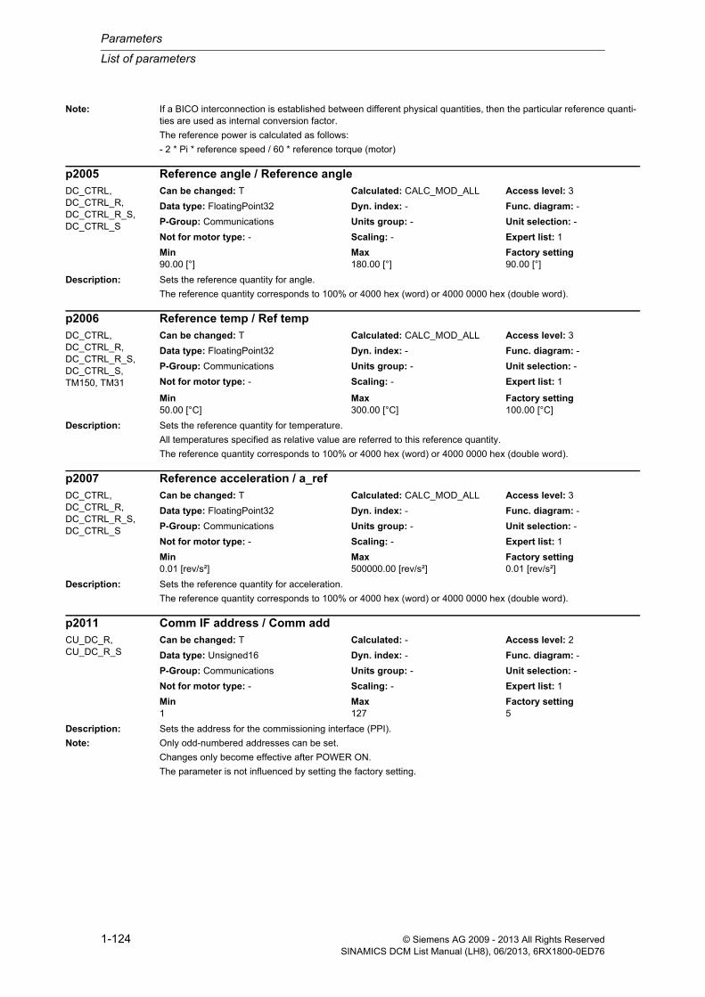
Parameters
List of parameters
1-124 © Siemens AG 2009 - 2013 All Rights ReservedSINAMICS DCM List Manual (LH8), 06/2013, 6RX1800-0ED76
Note: If a BICO interconnection is established between different physical quantities, then the particular reference quanti-ties are used as internal conversion factor.
The reference power is calculated as follows:
- 2 * Pi * reference speed / 60 * reference torque (motor)
Description: Sets the reference quantity for angle.
The reference quantity corresponds to 100% or 4000 hex (word) or 4000 0000 hex (double word).
Description: Sets the reference quantity for temperature.
All temperatures specified as relative value are referred to this reference quantity.
The reference quantity corresponds to 100% or 4000 hex (word) or 4000 0000 hex (double word).
Description: Sets the reference quantity for acceleration.
The reference quantity corresponds to 100% or 4000 hex (word) or 4000 0000 hex (double word).
Description: Sets the address for the commissioning interface (PPI).
Note: Only odd-numbered addresses can be set.
Changes only become effective after POWER ON.
The parameter is not influenced by setting the factory setting.
p2005 Reference angle / Reference angleDC_CTRL, DC_CTRL_R, DC_CTRL_R_S, DC_CTRL_S
Can be changed: T Calculated: CALC_MOD_ALL Access level: 3
Data type: FloatingPoint32 Dyn. index: - Func. diagram: -
P-Group: Communications Units group: - Unit selection: -
Not for motor type: - Scaling: - Expert list: 1
Min Max Factory setting 90.00 [°] 180.00 [°] 90.00 [°]
p2006 Reference temp / Ref tempDC_CTRL, DC_CTRL_R, DC_CTRL_R_S, DC_CTRL_S, TM150, TM31
Can be changed: T Calculated: CALC_MOD_ALL Access level: 3
Data type: FloatingPoint32 Dyn. index: - Func. diagram: -
P-Group: Communications Units group: - Unit selection: -
Not for motor type: - Scaling: - Expert list: 1
Min Max Factory setting 50.00 [°C] 300.00 [°C] 100.00 [°C]
p2007 Reference acceleration / a_refDC_CTRL, DC_CTRL_R, DC_CTRL_R_S, DC_CTRL_S
Can be changed: T Calculated: CALC_MOD_ALL Access level: 3
Data type: FloatingPoint32 Dyn. index: - Func. diagram: -
P-Group: Communications Units group: - Unit selection: -
Not for motor type: - Scaling: - Expert list: 1
Min Max Factory setting 0.01 [rev/s²] 500000.00 [rev/s²] 0.01 [rev/s²]
p2011 Comm IF address / Comm addCU_DC_R, CU_DC_R_S
Can be changed: T Calculated: - Access level: 2
Data type: Unsigned16 Dyn. index: - Func. diagram: -
P-Group: Communications Units group: - Unit selection: -
Not for motor type: - Scaling: - Expert list: 1
Min Max Factory setting 1 127 5

List of parameters
Parameters
1-125© Siemens AG 2009 - 2013 All Rights ReservedSINAMICS DCM List Manual (LH8), 06/2013, 6RX1800-0ED76
Description: Sets the address for the commissioning interface (PPI).
Note: Only odd-numbered addresses can be set.
Changes only become effective after POWER ON.
The parameter is not influenced by setting the factory setting.
Description: Displays the receive errors at the commissioning interface (RS232).
Index: [0] = Number of error-free telegrams[1] = Number of rejected telegrams[2] = Number of framing errors[3] = Number of overrun errors[4] = Number of parity errors[5] = Number of starting character errors[6] = Number of checksum errors[7] = Number of length errors
Description: Sets the baud rate for the fieldbus interface USS.
Value: 4: 2400 baud5: 4800 baud6: 9600 baud7: 19200 baud8: 38400 baud9: 57600 baud10: 76800 baud11: 93750 baud12: 115200 baud13: 187500 baud
Note: Fieldbus IF: Fieldbus interface
Changes only become effective after POWER ON.
The parameter is not influenced by setting the factory setting.
The parameter is set to the factory setting when the protocol is reselected.
p2011 Comm IF address / Comm addCU_DC, CU_DC_S Can be changed: T Calculated: - Access level: 2
Data type: Unsigned16 Dyn. index: - Func. diagram: -
P-Group: Communications Units group: - Unit selection: -
Not for motor type: - Scaling: - Expert list: 1
Min Max Factory setting 1 127 3
r2019[0...7] Comm IF error statistics / Comm errCU_DC, CU_DC_R, CU_DC_R_S, CU_DC_S
Can be changed: - Calculated: - Access level: 4
Data type: Unsigned32 Dyn. index: - Func. diagram: -
P-Group: Communications Units group: - Unit selection: -
Not for motor type: - Scaling: - Expert list: 1
Min Max Factory setting - - -
p2020 Field bus interface baud rate / Field bus baudCU_DC, CU_DC_R, CU_DC_R_S, CU_DC_S
Can be changed: T Calculated: - Access level: 2
Data type: Integer16 Dyn. index: - Func. diagram: -
P-Group: Communications Units group: - Unit selection: -
Not for motor type: - Scaling: - Expert list: 1
Min Max Factory setting 4 13 8

Parameters
List of parameters
1-126 © Siemens AG 2009 - 2013 All Rights ReservedSINAMICS DCM List Manual (LH8), 06/2013, 6RX1800-0ED76
Description: Sets the address for the fieldbus interface USS.
Dependency: Refer to: p2030
Note: Changes only become effective after POWER ON.
The parameter is not influenced by setting the factory setting.
The parameter is set to the factory setting when the protocol is reselected.
Description: Sets the number of 16-bit words in the PZD part of the USS telegram for the field bus interface.
Dependency: Refer to: p2030
Note: The parameter is not influenced by setting the factory setting.
Description: Sets the number of 16-bit words in the PKW part of the USS telegram for the field bus interface.
Value: 0: PKW 0 words3: PKW 3 words4: PKW 4 words127: PKW variable
Dependency: Refer to: p2030
Note: The parameter is not influenced by setting the factory setting.
Description: Displays the receive errors on the field bus interface (USS).
Index: [0] = Number of error-free telegrams[1] = Number of rejected telegrams[2] = Number of framing errors[3] = Number of overrun errors[4] = Number of parity errors[5] = Number of starting character errors
p2021 Field bus interface address / Field bus addressCU_DC, CU_DC_R, CU_DC_R_S, CU_DC_S
Can be changed: T Calculated: - Access level: 2
Data type: Unsigned16 Dyn. index: - Func. diagram: -
P-Group: Communications Units group: - Unit selection: -
Not for motor type: - Scaling: - Expert list: 1
Min Max Factory setting 0 31 0
p2022 Field bus int USS PZD no. / Field bus USS PZDCU_DC, CU_DC_R, CU_DC_R_S, CU_DC_S
Can be changed: T Calculated: - Access level: 2
Data type: Unsigned16 Dyn. index: - Func. diagram: -
P-Group: Communications Units group: - Unit selection: -
Not for motor type: - Scaling: - Expert list: 1
Min Max Factory setting 0 16 2
p2023 Field bus int USS PKW no. / Field bus USS PKWCU_DC, CU_DC_R, CU_DC_R_S, CU_DC_S
Can be changed: T Calculated: - Access level: 2
Data type: Integer16 Dyn. index: - Func. diagram: -
P-Group: Communications Units group: - Unit selection: -
Not for motor type: - Scaling: - Expert list: 1
Min Max Factory setting 0 127 127
r2029[0...7] Field bus int error statistics / Field bus errorCU_DC, CU_DC_R, CU_DC_R_S, CU_DC_S
Can be changed: - Calculated: - Access level: 3
Data type: Unsigned32 Dyn. index: - Func. diagram: -
P-Group: Communications Units group: - Unit selection: -
Not for motor type: - Scaling: - Expert list: 1
Min Max Factory setting - - -

List of parameters
Parameters
1-127© Siemens AG 2009 - 2013 All Rights ReservedSINAMICS DCM List Manual (LH8), 06/2013, 6RX1800-0ED76
[6] = Number of checksum errors[7] = Number of length errors
Description: Sets the communication protocol for the field bus interface.
Value: 0: No protocol1: USS3: PROFIBUS
Note: Changes only become effective after POWER ON.
The parameter is not influenced by setting the factory setting.
Description: Displays the effective control word 1 (STW1) of the drive for the master control.
Notice: The master control only influences control word 1 and speed setpoint 1. Other control words/setpoints can be trans-ferred from another automation device.
Note: OC: Operating condition
Description: Sets the drive object number for communication via the field bus interface (USS).
Dependency: Refer to: p0978
Note: p2035 defines the destination for USS parameter requests (PIV).
p0978[0] defines the destination for USS process data (PZD).
The parameter is available globally on all drive objects.
The parameter is not influenced by setting the factory setting.
p2030 Field bus int protocol selection / Field bus protocolCU_DC, CU_DC_R, CU_DC_R_S, CU_DC_S
Can be changed: T Calculated: - Access level: 1
Data type: Integer16 Dyn. index: - Func. diagram: -
P-Group: Communications Units group: - Unit selection: -
Not for motor type: - Scaling: - Expert list: 1
Min Max Factory setting 0 3 3
r2032 Master control control word effective / PcCtrl STW effDC_CTRL, DC_CTRL_R, DC_CTRL_R_S, DC_CTRL_S
Can be changed: - Calculated: - Access level: 2
Data type: Unsigned16 Dyn. index: - Func. diagram: -
P-Group: Displays, signals Units group: - Unit selection: -
Not for motor type: - Scaling: - Expert list: 1
Min Max Factory setting - - -
Bit field: Bit Signal name 1 signal 0 signal FP00 ON/OFF1 Yes No -01 OC / OFF2 Yes No -02 OC / OFF3 Yes No -03 Operation enable Yes No -04 Ramp-function generator enable Yes No -05 Start ramp-function generator Yes No -06 Speed setpoint enable Yes No -07 Acknowledge fault Yes No -08 Jog bit 0 Yes No 303009 Jog bit 1 Yes No 303010 Master ctrl by PLC Yes No -
p2035 Fieldbus interface USS PIV drive object number / Fieldbus USS DO_noCU_DC, CU_DC_R, CU_DC_R_S, CU_DC_S
Can be changed: U, T Calculated: - Access level: 2
Data type: Integer16 Dyn. index: - Func. diagram: -
P-Group: Communications Units group: - Unit selection: -
Not for motor type: - Scaling: - Expert list: 1
Min Max Factory setting 1 62 2

Parameters
List of parameters
1-128 © Siemens AG 2009 - 2013 All Rights ReservedSINAMICS DCM List Manual (LH8), 06/2013, 6RX1800-0ED76
Description: Sets the processing mode for PROFIdrive STW1.10 "master control by PLC".
Generally, control world 1 is received with the first receive word (PZD1) (this is in conformance to the PROFIdrive profile). The behavior of STW1.10 = 0 corresponds to that of the PROFIdrive profile. For other applications that deviate from this, the behavior can be adapted using this particular parameter.
Value: 0: Freeze setpoints and continue to process sign-of-life1: Freeze setpoints and sign-of-life2: Do not freeze setpoints
Recommend.: Do not change the setting p2037 = 0.
Note: If the STW1 is not transferred according to the PROFIdrive with PZD1 (with bit 10 "master control by PLC"), then p2037 should be set to 2.
Description: Sets the interface mode of the PROFIdrive control words and status words.
When selecting a telegram via p0922 (p2079), this parameter influences the device-specific assignment of the bits in the control and status words.
Value: 0: SINAMICS2: VIK-NAMUR
Dependency: Refer to: p0922, p2079
Notice: The parameter may be protected as a result of p0922 or p2079 and cannot be changed.
Description: Sets the serial interface for the debug monitor.
With p2039 = 1, the serial interface COM2 (X179) is set.
Other values are not permitted.
Description: Sets the monitoring time to monitor the process data received via the fieldbus interface.
If no process data is received within this time, then an appropriate message is output.
p2037 IF1 PROFIdrive STW1.10 = 0 mode / IF1 PD STW1.10=0DC_CTRL, DC_CTRL_R, DC_CTRL_R_S, DC_CTRL_S
Can be changed: T Calculated: - Access level: 3
Data type: Integer16 Dyn. index: - Func. diagram: -
P-Group: Communications Units group: - Unit selection: -
Not for motor type: - Scaling: - Expert list: 1
Min Max Factory setting 0 2 0
p2038 IF1 PROFIdrive STW/ZSW interface mode / PD STW/ZSW IF modeDC_CTRL, DC_CTRL_R, DC_CTRL_R_S, DC_CTRL_S
Can be changed: T Calculated: - Access level: 3
Data type: Integer16 Dyn. index: - Func. diagram: -
P-Group: Communications Units group: - Unit selection: -
Not for motor type: - Scaling: - Expert list: 1
Min Max Factory setting 0 2 0
p2039 Select debug monitor interface / Debug monit selectCU_DC, CU_DC_R, CU_DC_R_S, CU_DC_S
Can be changed: U, T Calculated: - Access level: 4
Data type: Unsigned16 Dyn. index: - Func. diagram: -
P-Group: Communications Units group: - Unit selection: -
Not for motor type: - Scaling: - Expert list: 1
Min Max Factory setting 0 3 1
p2040 Fieldbus interface monitoring time / Fieldbus t_monitCU_DC, CU_DC_R, CU_DC_R_S, CU_DC_S
Can be changed: U, T Calculated: - Access level: 3
Data type: FloatingPoint32 Dyn. index: - Func. diagram: -
P-Group: Communications Units group: - Unit selection: -
Not for motor type: - Scaling: - Expert list: 1
Min Max Factory setting 0 [ms] 1999999 [ms] 100 [ms]

List of parameters
Parameters
1-129© Siemens AG 2009 - 2013 All Rights ReservedSINAMICS DCM List Manual (LH8), 06/2013, 6RX1800-0ED76
Note: 0: The monitoring is de-activated.
Description: Sets the PROFIBUS Ident Number (PNO-ID).
SINAMICS can be operated with various identities on PROFIBUS. This allows the use of a PROFIBUS GSD that is independent of the device (e.g. PROFIdrive VIK-NAMUR with Ident Number 3AA0 hex).
Value: 0: SINAMICS1: VIK-NAMUR
Note: Every change only becomes effective after a POWER ON.
Description: Displays the PROFIdrive PZD state.
Dependency: Refer to: p2044
Note: When using the "setpoint failure" signal, the bus can be monitored and an application-specific response triggered when the setpoint fails.
Description: Sets the delay time to initiate fault F01910 after a setpoint failure.
The time until the fault is initiated can be used by the application. This means that is is possible to respond to the failure while the drive is still operational (e.g. emergency retraction).
Dependency: Refer to: r2043
Description: Sets the additional monitoring time to monitor the process data received via PROFIBUS.
The additional monitoring time enables short bus faults to be compensated.
If no process data is received within this time, then an appropriate message is output.
p2042 PROFIBUS Ident Number / PB Ident No.CU_DC, CU_DC_R, CU_DC_R_S, CU_DC_S
Can be changed: T Calculated: - Access level: 3
Data type: Integer16 Dyn. index: - Func. diagram: -
P-Group: Communications Units group: - Unit selection: -
Not for motor type: - Scaling: - Expert list: 1
Min Max Factory setting 0 1 0
r2043.0...2 BO: IF1 PROFIdrive PZD state / IF1 PD PZD stateCU_DC, CU_DC_R, CU_DC_R_S, CU_DC_S
Can be changed: - Calculated: - Access level: 3
Data type: Unsigned8 Dyn. index: - Func. diagram: 2410
P-Group: Communications Units group: - Unit selection: -
Not for motor type: - Scaling: - Expert list: 1
Min Max Factory setting - - -
Bit field: Bit Signal name 1 signal 0 signal FP00 Setpoint failure Yes No -02 Fieldbus oper Yes No -
p2044 IF1 PROFIdrive fault delay / IF1 PD fault delayDC_CTRL, DC_CTRL_R, DC_CTRL_R_S, DC_CTRL_S
Can be changed: U, T Calculated: - Access level: 3
Data type: FloatingPoint32 Dyn. index: - Func. diagram: 2410
P-Group: Communications Units group: - Unit selection: -
Not for motor type: - Scaling: - Expert list: 1
Min Max Factory setting 0 [s] 100 [s] 0 [s]
p2047 PROFIBUS additional monitoring time / PB suppl t_monitCU_DC, CU_DC_R, CU_DC_R_S, CU_DC_S
Can be changed: U, T Calculated: - Access level: 3
Data type: FloatingPoint32 Dyn. index: - Func. diagram: 2410
P-Group: Communications Units group: - Unit selection: -
Not for motor type: - Scaling: - Expert list: 1
Min Max Factory setting 0 [ms] 20000 [ms] 0 [ms]

Parameters
List of parameters
1-130 © Siemens AG 2009 - 2013 All Rights ReservedSINAMICS DCM List Manual (LH8), 06/2013, 6RX1800-0ED76
Recommend.: Do not set the additional monitoring time for clock-synchronous operation.
Note: For controller STOP, the additional monitoring time is not effective.
Description: Sets the sampling time for the cyclic interface 1 (IF1).
Note: The system only permits certain sampling times and after writing to this parameter, displays the value that has actu-ally been set.
For clock cycle synchronous operation, the specified bus cycle time applies (Tdp).
Description: Connector output to interconnect PZD (setpoints) with word format received from the PROFIdrive controller.
Index: [0] = PZD 1[1] = PZD 2[2] = PZD 3[3] = PZD 4[4] = PZD 5[5] = PZD 6[6] = PZD 7[7] = PZD 8[8] = PZD 9[9] = PZD 10[10] = PZD 11[11] = PZD 12[12] = PZD 13[13] = PZD 14[14] = PZD 15[15] = PZD 16[16] = PZD 17[17] = PZD 18[18] = PZD 19[19] = PZD 20
Note: IF1: Interface 1
Description: Connector output to interconnect PZD (setpoints) with word format received from the PROFIdrive controller.
Index: [0] = PZD 1[1] = PZD 2[2] = PZD 3
p2048 IF1 PROFIdrive PZD sampling time / IF1 PZD t_sampleCU_DC, CU_DC_R, CU_DC_R_S, CU_DC_S
Can be changed: C1(3) Calculated: - Access level: 3
Data type: FloatingPoint32 Dyn. index: - Func. diagram: -
P-Group: Communications Units group: - Unit selection: -
Not for motor type: - Scaling: - Expert list: 1
Min Max Factory setting 1.00 [ms] 16.00 [ms] 4.00 [ms]
r2050[0...19] CO: IF1 PROFIdrive PZD receive word / IF1 PZD recv wordCU_DC, CU_DC_R, CU_DC_R_S, CU_DC_S
Can be changed: - Calculated: - Access level: 3
Data type: Integer16 Dyn. index: - Func. diagram: -
P-Group: Communications Units group: - Unit selection: -
Not for motor type: - Scaling: 4000H Expert list: 1
Min Max Factory setting - - -
r2050[0...63] CO: IF1 PROFIdrive PZD receive word / IF1 PZD recv wordDC_CTRL, DC_CTRL_R, DC_CTRL_R_S, DC_CTRL_S
Can be changed: - Calculated: - Access level: 3
Data type: Integer16 Dyn. index: - Func. diagram: 2440
P-Group: Communications Units group: - Unit selection: -
Not for motor type: - Scaling: 4000H Expert list: 1
Min Max Factory setting - - -

List of parameters
Parameters
1-131© Siemens AG 2009 - 2013 All Rights ReservedSINAMICS DCM List Manual (LH8), 06/2013, 6RX1800-0ED76
[3] = PZD 4[4] = PZD 5[5] = PZD 6[6] = PZD 7[7] = PZD 8[8] = PZD 9[9] = PZD 10[10] = PZD 11[11] = PZD 12[12] = PZD 13[13] = PZD 14[14] = PZD 15[15] = PZD 16[16] = PZD 17[17] = PZD 18[18] = PZD 19[19] = PZD 20[20] = PZD 21[21] = PZD 22[22] = PZD 23[23] = PZD 24[24] = PZD 25[25] = PZD 26[26] = PZD 27[27] = PZD 28[28] = PZD 29[29] = PZD 30[30] = PZD 31[31] = PZD 32[32] = PZD 33[33] = PZD 34[34] = PZD 35[35] = PZD 36[36] = PZD 37[37] = PZD 38[38] = PZD 39[39] = PZD 40[40] = PZD 41[41] = PZD 42[42] = PZD 43[43] = PZD 44[44] = PZD 45[45] = PZD 46[46] = PZD 47[47] = PZD 48[48] = PZD 49[49] = PZD 50[50] = PZD 51[51] = PZD 52[52] = PZD 53[53] = PZD 54[54] = PZD 55[55] = PZD 56[56] = PZD 57[57] = PZD 58[58] = PZD 59[59] = PZD 60[60] = PZD 61[61] = PZD 62[62] = PZD 63[63] = PZD 64
Dependency: Refer to: r2060

Parameters
List of parameters
1-132 © Siemens AG 2009 - 2013 All Rights ReservedSINAMICS DCM List Manual (LH8), 06/2013, 6RX1800-0ED76
Notice: Where there is a multiple interconnection of a connector output, all the connector inputs must either have Integer or FloatingPoint data types.
A BICO interconnection for a single PZD can only take place either on r2050 or r2060.
Note: IF1: Interface 1
Description: Connector output to interconnect PZD (setpoints) with word format received from the PROFIdrive controller.
Index: [0] = PZD 1[1] = PZD 2[2] = PZD 3[3] = PZD 4[4] = PZD 5
Note: IF1: Interface 1
Description: Selects the PZD (actual values) with word format to be sent to the PROFIdrive controller.
Index: [0] = PZD 1[1] = PZD 2[2] = PZD 3[3] = PZD 4[4] = PZD 5[5] = PZD 6[6] = PZD 7[7] = PZD 8[8] = PZD 9[9] = PZD 10[10] = PZD 11[11] = PZD 12[12] = PZD 13[13] = PZD 14[14] = PZD 15[15] = PZD 16[16] = PZD 17[17] = PZD 18[18] = PZD 19[19] = PZD 20[20] = PZD 21[21] = PZD 22[22] = PZD 23[23] = PZD 24[24] = PZD 25
Notice: The parameter may be protected as a result of p0922 or p2079 and cannot be changed.
Note: IF1: Interface 1
r2050[0...4] CO: IF1 PROFIdrive PZD receive word / IF1 PZD recv wordTM150, TM15DI_DO, TM31
Can be changed: - Calculated: - Access level: 3
Data type: Integer16 Dyn. index: - Func. diagram: -
P-Group: Communications Units group: - Unit selection: -
Not for motor type: - Scaling: 4000H Expert list: 1
Min Max Factory setting - - -
p2051[0...24] CI: IF1 PROFIdrive PZD send word / IF1 PZD send wordCU_DC, CU_DC_R, CU_DC_R_S, CU_DC_S
Can be changed: U, T Calculated: - Access level: 3
Data type: Unsigned32 / Integer16 Dyn. index: - Func. diagram: 2450, 2483
P-Group: Communications Units group: - Unit selection: -
Not for motor type: - Scaling: 4000H Expert list: 1
Min Max Factory setting - - 0

List of parameters
Parameters
1-133© Siemens AG 2009 - 2013 All Rights ReservedSINAMICS DCM List Manual (LH8), 06/2013, 6RX1800-0ED76
Description: Selects the PZD (actual values) with word format to be sent to the PROFIdrive controller.
Index: [0] = PZD 1[1] = PZD 2[2] = PZD 3[3] = PZD 4[4] = PZD 5[5] = PZD 6[6] = PZD 7[7] = PZD 8[8] = PZD 9[9] = PZD 10[10] = PZD 11[11] = PZD 12[12] = PZD 13[13] = PZD 14[14] = PZD 15[15] = PZD 16[16] = PZD 17[17] = PZD 18[18] = PZD 19[19] = PZD 20[20] = PZD 21[21] = PZD 22[22] = PZD 23[23] = PZD 24[24] = PZD 25[25] = PZD 26[26] = PZD 27[27] = PZD 28[28] = PZD 29[29] = PZD 30[30] = PZD 31[31] = PZD 32[32] = PZD 33[33] = PZD 34[34] = PZD 35[35] = PZD 36[36] = PZD 37[37] = PZD 38[38] = PZD 39[39] = PZD 40[40] = PZD 41[41] = PZD 42[42] = PZD 43[43] = PZD 44[44] = PZD 45[45] = PZD 46[46] = PZD 47[47] = PZD 48[48] = PZD 49[49] = PZD 50[50] = PZD 51[51] = PZD 52
p2051[0...63] CI: IF1 PROFIdrive PZD send word / IF1 PZD send wordDC_CTRL, DC_CTRL_R, DC_CTRL_R_S, DC_CTRL_S
Can be changed: U, T Calculated: - Access level: 3
Data type: Unsigned32 / Integer16 Dyn. index: - Func. diagram: 2450, 2470, 2483
P-Group: Communications Units group: - Unit selection: -
Not for motor type: - Scaling: 4000H Expert list: 1
Min Max Factory setting - - 0

Parameters
List of parameters
1-134 © Siemens AG 2009 - 2013 All Rights ReservedSINAMICS DCM List Manual (LH8), 06/2013, 6RX1800-0ED76
[52] = PZD 53[53] = PZD 54[54] = PZD 55[55] = PZD 56[56] = PZD 57[57] = PZD 58[58] = PZD 59[59] = PZD 60[60] = PZD 61[61] = PZD 62[62] = PZD 63[63] = PZD 64
Dependency: Refer to: p2061
Notice: The parameter may be protected as a result of p0922 or p2079 and cannot be changed.
Note: IF1: Interface 1
Description: Selects the PZD (actual values) with word format to be sent to the PROFIdrive controller.
Index: [0] = PZD 1[1] = PZD 2[2] = PZD 3[3] = PZD 4[4] = PZD 5
Notice: The parameter may be protected as a result of p0922 or p2079 and cannot be changed.
Note: IF1: Interface 1
Description: Displays the PZD (actual values) with word format sent to the PROFIdrive controller.
Index: [0] = PZD 1[1] = PZD 2[2] = PZD 3[3] = PZD 4[4] = PZD 5[5] = PZD 6[6] = PZD 7[7] = PZD 8[8] = PZD 9[9] = PZD 10[10] = PZD 11[11] = PZD 12[12] = PZD 13[13] = PZD 14[14] = PZD 15[15] = PZD 16[16] = PZD 17[17] = PZD 18
p2051[0...4] CI: IF1 PROFIdrive PZD send word / IF1 PZD send wordTM150, TM15DI_DO, TM31
Can be changed: U, T Calculated: - Access level: 3
Data type: Unsigned32 / Integer16 Dyn. index: - Func. diagram: -
P-Group: Communications Units group: - Unit selection: -
Not for motor type: - Scaling: 4000H Expert list: 1
Min Max Factory setting - - 0
r2053[0...24] IF1 PROFIdrive diagnostics PZD send word / IF1 diag send wordCU_DC, CU_DC_R, CU_DC_R_S, CU_DC_S
Can be changed: - Calculated: - Access level: 3
Data type: Unsigned16 Dyn. index: - Func. diagram: 2483
P-Group: Communications Units group: - Unit selection: -
Not for motor type: - Scaling: - Expert list: 1
Min Max Factory setting - - -

List of parameters
Parameters
1-135© Siemens AG 2009 - 2013 All Rights ReservedSINAMICS DCM List Manual (LH8), 06/2013, 6RX1800-0ED76
[18] = PZD 19[19] = PZD 20[20] = PZD 21[21] = PZD 22[22] = PZD 23[23] = PZD 24[24] = PZD 25
Note: IF1: Interface 1
Description: Displays the PZD (actual values) with word format sent to the PROFIdrive controller.
Index: [0] = PZD 1[1] = PZD 2[2] = PZD 3[3] = PZD 4[4] = PZD 5[5] = PZD 6[6] = PZD 7[7] = PZD 8[8] = PZD 9[9] = PZD 10[10] = PZD 11[11] = PZD 12[12] = PZD 13[13] = PZD 14[14] = PZD 15[15] = PZD 16[16] = PZD 17[17] = PZD 18[18] = PZD 19[19] = PZD 20[20] = PZD 21[21] = PZD 22[22] = PZD 23[23] = PZD 24[24] = PZD 25[25] = PZD 26[26] = PZD 27
Bit field: Bit Signal name 1 signal 0 signal FP00 Bit 0 ON OFF -01 Bit 1 ON OFF -02 Bit 2 ON OFF -03 Bit 3 ON OFF -04 Bit 4 ON OFF -05 Bit 5 ON OFF -06 Bit 6 ON OFF -07 Bit 7 ON OFF -08 Bit 8 ON OFF -09 Bit 9 ON OFF -10 Bit 10 ON OFF -11 Bit 11 ON OFF -12 Bit 12 ON OFF -13 Bit 13 ON OFF -14 Bit 14 ON OFF -15 Bit 15 ON OFF -
r2053[0...63] IF1 PROFIdrive diagnostics PZD send word / IF1 diag send wordDC_CTRL, DC_CTRL_R, DC_CTRL_R_S, DC_CTRL_S
Can be changed: - Calculated: - Access level: 3
Data type: Unsigned16 Dyn. index: - Func. diagram: 2450, 2470
P-Group: Communications Units group: - Unit selection: -
Not for motor type: - Scaling: - Expert list: 1
Min Max Factory setting - - -

Parameters
List of parameters
1-136 © Siemens AG 2009 - 2013 All Rights ReservedSINAMICS DCM List Manual (LH8), 06/2013, 6RX1800-0ED76
[27] = PZD 28[28] = PZD 29[29] = PZD 30[30] = PZD 31[31] = PZD 32[32] = PZD 33[33] = PZD 34[34] = PZD 35[35] = PZD 36[36] = PZD 37[37] = PZD 38[38] = PZD 39[39] = PZD 40[40] = PZD 41[41] = PZD 42[42] = PZD 43[43] = PZD 44[44] = PZD 45[45] = PZD 46[46] = PZD 47[47] = PZD 48[48] = PZD 49[49] = PZD 50[50] = PZD 51[51] = PZD 52[52] = PZD 53[53] = PZD 54[54] = PZD 55[55] = PZD 56[56] = PZD 57[57] = PZD 58[58] = PZD 59[59] = PZD 60[60] = PZD 61[61] = PZD 62[62] = PZD 63[63] = PZD 64
Dependency: Refer to: p2051, p2061
Note: IF1: Interface 1
Bit field: Bit Signal name 1 signal 0 signal FP00 Bit 0 ON OFF -01 Bit 1 ON OFF -02 Bit 2 ON OFF -03 Bit 3 ON OFF -04 Bit 4 ON OFF -05 Bit 5 ON OFF -06 Bit 6 ON OFF -07 Bit 7 ON OFF -08 Bit 8 ON OFF -09 Bit 9 ON OFF -10 Bit 10 ON OFF -11 Bit 11 ON OFF -12 Bit 12 ON OFF -13 Bit 13 ON OFF -14 Bit 14 ON OFF -15 Bit 15 ON OFF -

List of parameters
Parameters
1-137© Siemens AG 2009 - 2013 All Rights ReservedSINAMICS DCM List Manual (LH8), 06/2013, 6RX1800-0ED76
Description: Displays the PZD (actual values) with word format sent to the PROFIdrive controller.
Index: [0] = PZD 1[1] = PZD 2[2] = PZD 3[3] = PZD 4[4] = PZD 5
Note: IF1: Interface 1
Description: Status display for the PROFIBUS interface.
Value: 0: OFF1: No connection (search for baud rate)2: Connection OK (baud rate found)3: Cyclic connection with master (data exchange)4: Cyclic data OK
Note: Re r2054 = 3:
In state 3 (the LED flashes green), a cyclic connection has been established to the PROFIBUS master; however, one of the following prerequisites is missing for cyclic operation:
- No setpoints are being received as the PROFIBUS master is in the STOP condition.
Only for clock-cycle synchronous operation, the following applies:
- The drive is not in synchronism as the global control (GC) has an error.
Re r2054 = 4:
In the status 4 (LED green), the cyclic connection to the PROFIBUS master has been established and setpoints are being received. The clock cycle synchronization is OK, the global control (GC) is error-free.
This state does not provide any statement regarding the quality of the clock cycle synchronous sign-of-life charac-ters on the drive objects.
r2053[0...4] IF1 PROFIdrive diagnostics PZD send word / IF1 diag send wordTM150, TM15DI_DO, TM31
Can be changed: - Calculated: - Access level: 3
Data type: Unsigned16 Dyn. index: - Func. diagram: -
P-Group: Communications Units group: - Unit selection: -
Not for motor type: - Scaling: - Expert list: 1
Min Max Factory setting - - -
Bit field: Bit Signal name 1 signal 0 signal FP00 Bit 0 ON OFF -01 Bit 1 ON OFF -02 Bit 2 ON OFF -03 Bit 3 ON OFF -04 Bit 4 ON OFF -05 Bit 5 ON OFF -06 Bit 6 ON OFF -07 Bit 7 ON OFF -08 Bit 8 ON OFF -09 Bit 9 ON OFF -10 Bit 10 ON OFF -11 Bit 11 ON OFF -12 Bit 12 ON OFF -13 Bit 13 ON OFF -14 Bit 14 ON OFF -15 Bit 15 ON OFF -
r2054 PROFIBUS status / PB statusCU_DC, CU_DC_R, CU_DC_R_S, CU_DC_S
Can be changed: - Calculated: - Access level: 3
Data type: Integer16 Dyn. index: - Func. diagram: 2410
P-Group: Communications Units group: - Unit selection: -
Not for motor type: - Scaling: - Expert list: 1
Min Max Factory setting 0 4 -
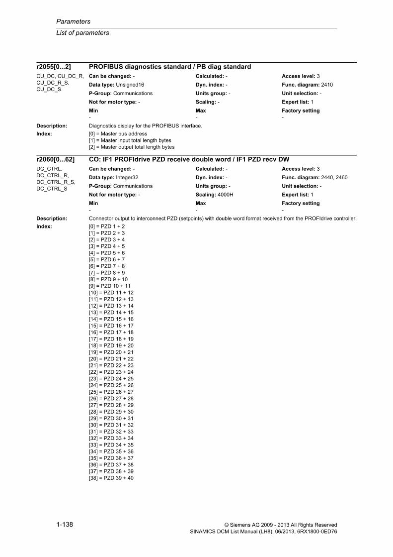
Parameters
List of parameters
1-138 © Siemens AG 2009 - 2013 All Rights ReservedSINAMICS DCM List Manual (LH8), 06/2013, 6RX1800-0ED76
Description: Diagnostics display for the PROFIBUS interface.
Index: [0] = Master bus address[1] = Master input total length bytes[2] = Master output total length bytes
Description: Connector output to interconnect PZD (setpoints) with double word format received from the PROFIdrive controller.
Index: [0] = PZD 1 + 2[1] = PZD 2 + 3[2] = PZD 3 + 4[3] = PZD 4 + 5[4] = PZD 5 + 6[5] = PZD 6 + 7[6] = PZD 7 + 8[7] = PZD 8 + 9[8] = PZD 9 + 10[9] = PZD 10 + 11[10] = PZD 11 + 12[11] = PZD 12 + 13[12] = PZD 13 + 14[13] = PZD 14 + 15[14] = PZD 15 + 16[15] = PZD 16 + 17[16] = PZD 17 + 18[17] = PZD 18 + 19[18] = PZD 19 + 20[19] = PZD 20 + 21[20] = PZD 21 + 22[21] = PZD 22 + 23[22] = PZD 23 + 24[23] = PZD 24 + 25[24] = PZD 25 + 26[25] = PZD 26 + 27[26] = PZD 27 + 28[27] = PZD 28 + 29[28] = PZD 29 + 30[29] = PZD 30 + 31[30] = PZD 31 + 32[31] = PZD 32 + 33[32] = PZD 33 + 34[33] = PZD 34 + 35[34] = PZD 35 + 36[35] = PZD 36 + 37[36] = PZD 37 + 38[37] = PZD 38 + 39[38] = PZD 39 + 40
r2055[0...2] PROFIBUS diagnostics standard / PB diag standardCU_DC, CU_DC_R, CU_DC_R_S, CU_DC_S
Can be changed: - Calculated: - Access level: 3
Data type: Unsigned16 Dyn. index: - Func. diagram: 2410
P-Group: Communications Units group: - Unit selection: -
Not for motor type: - Scaling: - Expert list: 1
Min Max Factory setting - - -
r2060[0...62] CO: IF1 PROFIdrive PZD receive double word / IF1 PZD recv DWDC_CTRL, DC_CTRL_R, DC_CTRL_R_S, DC_CTRL_S
Can be changed: - Calculated: - Access level: 3
Data type: Integer32 Dyn. index: - Func. diagram: 2440, 2460
P-Group: Communications Units group: - Unit selection: -
Not for motor type: - Scaling: 4000H Expert list: 1
Min Max Factory setting - - -

List of parameters
Parameters
1-139© Siemens AG 2009 - 2013 All Rights ReservedSINAMICS DCM List Manual (LH8), 06/2013, 6RX1800-0ED76
[39] = PZD 40 + 41[40] = PZD 41 + 42[41] = PZD 42 + 43[42] = PZD 43 + 44[43] = PZD 44 + 45[44] = PZD 45 + 46[45] = PZD 46 + 47[46] = PZD 47 + 48[47] = PZD 48 + 49[48] = PZD 49 + 50[49] = PZD 50 + 51[50] = PZD 51 + 52[51] = PZD 52 + 53[52] = PZD 53 + 54[53] = PZD 54 + 55[54] = PZD 55 + 56[55] = PZD 56 + 57[56] = PZD 57 + 58[57] = PZD 58 + 59[58] = PZD 59 + 60[59] = PZD 60 + 61[60] = PZD 61 + 62[61] = PZD 62 + 63[62] = PZD 63 + 64
Dependency: Refer to: r2050
Notice: Where there is a multiple interconnection of a connector output, all the connector inputs must either have Integer or FloatingPoint data types.
A BICO interconnection for a single PZD can only take place either on r2050 or r2060.
A maximum of 4 indices of the "trace" function can be used.
Note: IF1: Interface 1
Description: Selects the PZD (actual values) with double word format to be sent to the PROFIdrive controller.
Index: [0] = PZD 1 + 2[1] = PZD 2 + 3[2] = PZD 3 + 4[3] = PZD 4 + 5[4] = PZD 5 + 6[5] = PZD 6 + 7[6] = PZD 7 + 8[7] = PZD 8 + 9[8] = PZD 9 + 10[9] = PZD 10 + 11[10] = PZD 11 + 12[11] = PZD 12 + 13[12] = PZD 13 + 14[13] = PZD 14 + 15[14] = PZD 15 + 16[15] = PZD 16 + 17[16] = PZD 17 + 18[17] = PZD 18 + 19[18] = PZD 19 + 20[19] = PZD 20 + 21[20] = PZD 21 + 22
p2061[0...62] CI: IF1 PROFIdrive PZD send double word / IF1 PZD send DWDC_CTRL, DC_CTRL_R, DC_CTRL_R_S, DC_CTRL_S
Can be changed: U, T Calculated: - Access level: 3
Data type: Unsigned32 / Integer32 Dyn. index: - Func. diagram: 2450, 2470
P-Group: Communications Units group: - Unit selection: -
Not for motor type: - Scaling: 4000H Expert list: 1
Min Max Factory setting - - 0

Parameters
List of parameters
1-140 © Siemens AG 2009 - 2013 All Rights ReservedSINAMICS DCM List Manual (LH8), 06/2013, 6RX1800-0ED76
[21] = PZD 22 + 23[22] = PZD 23 + 24[23] = PZD 24 + 25[24] = PZD 25 + 26[25] = PZD 26 + 27[26] = PZD 27 + 28[27] = PZD 28 + 29[28] = PZD 29 + 30[29] = PZD 30 + 31[30] = PZD 31 + 32[31] = PZD 32 + 33[32] = PZD 33 + 34[33] = PZD 34 + 35[34] = PZD 35 + 36[35] = PZD 36 + 37[36] = PZD 37 + 38[37] = PZD 38 + 39[38] = PZD 39 + 40[39] = PZD 40 + 41[40] = PZD 41 + 42[41] = PZD 42 + 43[42] = PZD 43 + 44[43] = PZD 44 + 45[44] = PZD 45 + 46[45] = PZD 46 + 47[46] = PZD 47 + 48[47] = PZD 48 + 49[48] = PZD 49 + 50[49] = PZD 50 + 51[50] = PZD 51 + 52[51] = PZD 52 + 53[52] = PZD 53 + 54[53] = PZD 54 + 55[54] = PZD 55 + 56[55] = PZD 56 + 57[56] = PZD 57 + 58[57] = PZD 58 + 59[58] = PZD 59 + 60[59] = PZD 60 + 61[60] = PZD 61 + 62[61] = PZD 62 + 63[62] = PZD 63 + 64
Dependency: Refer to: p2051
Notice: A BICO interconnection for a single PZD can only take place either on p2051 or p2061.
The parameter may be protected as a result of p0922 or p2079 and cannot be changed.
Note: IF1: Interface 1
Description: Displays the PZD (actual values) with double word format sent to the PROFIdrive controller.
Index: [0] = PZD 1 + 2[1] = PZD 2 + 3[2] = PZD 3 + 4[3] = PZD 4 + 5[4] = PZD 5 + 6[5] = PZD 6 + 7
r2063[0...62] IF1 PROFIdrive diagnostics PZD send double word / IF1 diag send DWDC_CTRL, DC_CTRL_R, DC_CTRL_R_S, DC_CTRL_S
Can be changed: - Calculated: - Access level: 3
Data type: Unsigned32 Dyn. index: - Func. diagram: 2450, 2470
P-Group: Communications Units group: - Unit selection: -
Not for motor type: - Scaling: - Expert list: 1
Min Max Factory setting - - -

List of parameters
Parameters
1-141© Siemens AG 2009 - 2013 All Rights ReservedSINAMICS DCM List Manual (LH8), 06/2013, 6RX1800-0ED76
[6] = PZD 7 + 8[7] = PZD 8 + 9[8] = PZD 9 + 10[9] = PZD 10 + 11[10] = PZD 11 + 12[11] = PZD 12 + 13[12] = PZD 13 + 14[13] = PZD 14 + 15[14] = PZD 15 + 16[15] = PZD 16 + 17[16] = PZD 17 + 18[17] = PZD 18 + 19[18] = PZD 19 + 20[19] = PZD 20 + 21[20] = PZD 21 + 22[21] = PZD 22 + 23[22] = PZD 23 + 24[23] = PZD 24 + 25[24] = PZD 25 + 26[25] = PZD 26 + 27[26] = PZD 27 + 28[27] = PZD 28 + 29[28] = PZD 29 + 30[29] = PZD 30 + 31[30] = PZD 31 + 32[31] = PZD 32 + 33[32] = PZD 33 + 34[33] = PZD 34 + 35[34] = PZD 35 + 36[35] = PZD 36 + 37[36] = PZD 37 + 38[37] = PZD 38 + 39[38] = PZD 39 + 40[39] = PZD 40 + 41[40] = PZD 41 + 42[41] = PZD 42 + 43[42] = PZD 43 + 44[43] = PZD 44 + 45[44] = PZD 45 + 46[45] = PZD 46 + 47[46] = PZD 47 + 48[47] = PZD 48 + 49[48] = PZD 49 + 50[49] = PZD 50 + 51[50] = PZD 51 + 52[51] = PZD 52 + 53[52] = PZD 53 + 54[53] = PZD 54 + 55[54] = PZD 55 + 56[55] = PZD 56 + 57[56] = PZD 57 + 58[57] = PZD 58 + 59[58] = PZD 59 + 60[59] = PZD 60 + 61[60] = PZD 61 + 62[61] = PZD 62 + 63[62] = PZD 63 + 64
Bit field: Bit Signal name 1 signal 0 signal FP00 Bit 0 ON OFF -01 Bit 1 ON OFF -02 Bit 2 ON OFF -03 Bit 3 ON OFF -04 Bit 4 ON OFF -

Parameters
List of parameters
1-142 © Siemens AG 2009 - 2013 All Rights ReservedSINAMICS DCM List Manual (LH8), 06/2013, 6RX1800-0ED76
Notice: A maximum of 4 indices of the "trace" function can be used.
Note: IF1: Interface 1
Description: Displays the last parameter received from the PROFIBUS/PROFINET controller for clock synchronism.
The parameters for clock synchronism are created when configuring the bus and are transferred at the start of cyclic operation from the controller to the device.
Index: [0] = Clock synchronous mode activated[1] = Bus cycle time (Tdp) [µs][2] = Master cycle time (Tmapc) [µs][3] = Instant of actual value acquisition (Ti) [µs][4] = Instant of setpoint acquisition (To) [µs][5] = Data exchange interval (Tdx) [µs][6] = PLL window (Tpll-w) [1/12 µs][7] = PLL delay time (Tpll-d) [1/12 µs]
Description: Displays how often the sign-of-life from the clock synchronous PROFIBUS/PROFINET controller last failed.
05 Bit 5 ON OFF -06 Bit 6 ON OFF -07 Bit 7 ON OFF -08 Bit 8 ON OFF -09 Bit 9 ON OFF -10 Bit 10 ON OFF -11 Bit 11 ON OFF -12 Bit 12 ON OFF -13 Bit 13 ON OFF -14 Bit 14 ON OFF -15 Bit 15 ON OFF -16 Bit 16 ON OFF -17 Bit 17 ON OFF -18 Bit 18 ON OFF -19 Bit 19 ON OFF -20 Bit 20 ON OFF -21 Bit 21 ON OFF -22 Bit 22 ON OFF -23 Bit 23 ON OFF -24 Bit 24 ON OFF -25 Bit 25 ON OFF -26 Bit 26 ON OFF -27 Bit 27 ON OFF -28 Bit 28 ON OFF -29 Bit 29 ON OFF -30 Bit 30 ON OFF -31 Bit 31 ON OFF -
r2064[0...7] PB/PN diagnostics clock cycle synchronism / PB/PN diag clockCU_DC, CU_DC_R, CU_DC_R_S, CU_DC_S
Can be changed: - Calculated: - Access level: 3
Data type: Integer32 Dyn. index: - Func. diagram: -
P-Group: Communications Units group: - Unit selection: -
Not for motor type: - Scaling: - Expert list: 1
Min Max Factory setting - - -
r2065 PB/PN controller sign of life diagnostics / PB/PN ctr SoL diagCU_DC, CU_DC_R, CU_DC_R_S, CU_DC_S
Can be changed: - Calculated: - Access level: 3
Data type: Unsigned16 Dyn. index: - Func. diagram: -
P-Group: Communications Units group: - Unit selection: -
Not for motor type: - Scaling: - Expert list: 1
Min Max Factory setting - - -

List of parameters
Parameters
1-143© Siemens AG 2009 - 2013 All Rights ReservedSINAMICS DCM List Manual (LH8), 06/2013, 6RX1800-0ED76
Description: Display for the maximum interconnected PZD in the receive/send direction
Index 0: receive (r2050, r2060)
Index 1: send (p2051, p2061)
Description: Displays the PROFIBUS address of the sender from which the process data (PZD) is received.
Index: [0] = PZD 1[1] = PZD 2[2] = PZD 3[3] = PZD 4[4] = PZD 5[5] = PZD 6[6] = PZD 7[7] = PZD 8[8] = PZD 9[9] = PZD 10[10] = PZD 11[11] = PZD 12[12] = PZD 13[13] = PZD 14[14] = PZD 15[15] = PZD 16[16] = PZD 17[17] = PZD 18[18] = PZD 19[19] = PZD 20
Note: IF1: Interface 1
Value range:
0 - 125: Bus address of the sender
65535: not assigned
Description: Displays the PROFIBUS address of the sender from which the process data (PZD) is received.
Index: [0] = PZD 1[1] = PZD 2[2] = PZD 3
r2067[0...1] IF1 PZD maximum interconnected / IF1 PZDmaxInterconAll objects Can be changed: - Calculated: - Access level: 3
Data type: Unsigned16 Dyn. index: - Func. diagram: -
P-Group: Communications Units group: - Unit selection: -
Not for motor type: - Scaling: - Expert list: 1
Min Max Factory setting - - -
r2074[0...19] IF1 PROFIdrive diagnostics bus address PZD receive / IF1diag addr recvCU_DC, CU_DC_R, CU_DC_R_S, CU_DC_S
Can be changed: - Calculated: - Access level: 3
Data type: Unsigned16 Dyn. index: - Func. diagram: -
P-Group: Communications Units group: - Unit selection: -
Not for motor type: - Scaling: - Expert list: 1
Min Max Factory setting - - -
r2074[0...63] IF1 PROFIdrive diagnostics bus address PZD receive / IF1diag addr recvDC_CTRL, DC_CTRL_R, DC_CTRL_R_S, DC_CTRL_S
Can be changed: - Calculated: - Access level: 3
Data type: Unsigned16 Dyn. index: - Func. diagram: -
P-Group: Communications Units group: - Unit selection: -
Not for motor type: - Scaling: - Expert list: 1
Min Max Factory setting - - -

Parameters
List of parameters
1-144 © Siemens AG 2009 - 2013 All Rights ReservedSINAMICS DCM List Manual (LH8), 06/2013, 6RX1800-0ED76
[3] = PZD 4[4] = PZD 5[5] = PZD 6[6] = PZD 7[7] = PZD 8[8] = PZD 9[9] = PZD 10[10] = PZD 11[11] = PZD 12[12] = PZD 13[13] = PZD 14[14] = PZD 15[15] = PZD 16[16] = PZD 17[17] = PZD 18[18] = PZD 19[19] = PZD 20[20] = PZD 21[21] = PZD 22[22] = PZD 23[23] = PZD 24[24] = PZD 25[25] = PZD 26[26] = PZD 27[27] = PZD 28[28] = PZD 29[29] = PZD 30[30] = PZD 31[31] = PZD 32[32] = PZD 33[33] = PZD 34[34] = PZD 35[35] = PZD 36[36] = PZD 37[37] = PZD 38[38] = PZD 39[39] = PZD 40[40] = PZD 41[41] = PZD 42[42] = PZD 43[43] = PZD 44[44] = PZD 45[45] = PZD 46[46] = PZD 47[47] = PZD 48[48] = PZD 49[49] = PZD 50[50] = PZD 51[51] = PZD 52[52] = PZD 53[53] = PZD 54[54] = PZD 55[55] = PZD 56[56] = PZD 57[57] = PZD 58[58] = PZD 59[59] = PZD 60[60] = PZD 61[61] = PZD 62[62] = PZD 63[63] = PZD 64

List of parameters
Parameters
1-145© Siemens AG 2009 - 2013 All Rights ReservedSINAMICS DCM List Manual (LH8), 06/2013, 6RX1800-0ED76
Note: IF1: Interface 1
Value range:
0 - 125: Bus address of the sender
65535: not assigned
Description: Displays the PROFIBUS address of the sender from which the process data (PZD) is received.
Index: [0] = PZD 1[1] = PZD 2[2] = PZD 3[3] = PZD 4[4] = PZD 5
Note: IF1: Interface 1
Value range:
0 - 125: Bus address of the sender
65535: not assigned
Description: Displays the PZD byte offset in the PROFIdrive receive telegram (controller output).
Index: [0] = PZD 1[1] = PZD 2[2] = PZD 3[3] = PZD 4[4] = PZD 5[5] = PZD 6[6] = PZD 7[7] = PZD 8[8] = PZD 9[9] = PZD 10[10] = PZD 11[11] = PZD 12[12] = PZD 13[13] = PZD 14[14] = PZD 15[15] = PZD 16[16] = PZD 17[17] = PZD 18[18] = PZD 19[19] = PZD 20
Note: IF1: Interface 1
Value range:
0 - 242: Byte offset
65535: not assigned
r2074[0...4] IF1 PROFIdrive diagnostics bus address PZD receive / IF1diag addr recvTM150, TM15DI_DO, TM31
Can be changed: - Calculated: - Access level: 3
Data type: Unsigned16 Dyn. index: - Func. diagram: -
P-Group: Communications Units group: - Unit selection: -
Not for motor type: - Scaling: - Expert list: 1
Min Max Factory setting - - -
r2075[0...19] IF1 PROFIdrive diagnostics telegram offset PZD receive / IF1 diag offs recvCU_DC, CU_DC_R, CU_DC_R_S, CU_DC_S
Can be changed: - Calculated: - Access level: 3
Data type: Unsigned16 Dyn. index: - Func. diagram: 2410
P-Group: Communications Units group: - Unit selection: -
Not for motor type: - Scaling: - Expert list: 1
Min Max Factory setting - - -
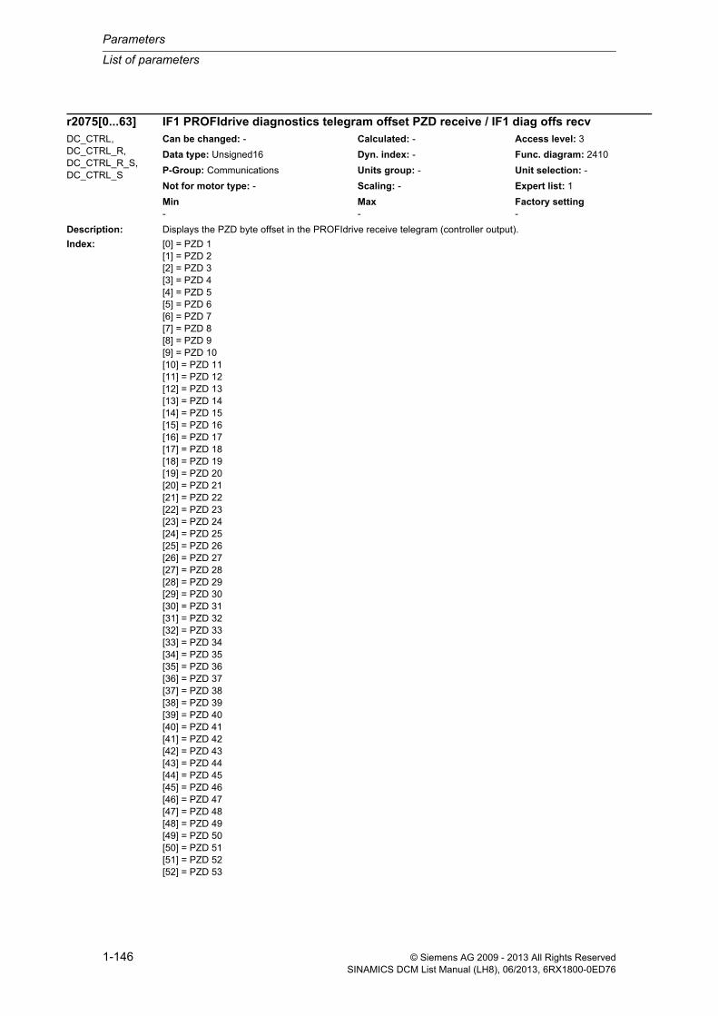
Parameters
List of parameters
1-146 © Siemens AG 2009 - 2013 All Rights ReservedSINAMICS DCM List Manual (LH8), 06/2013, 6RX1800-0ED76
Description: Displays the PZD byte offset in the PROFIdrive receive telegram (controller output).
Index: [0] = PZD 1[1] = PZD 2[2] = PZD 3[3] = PZD 4[4] = PZD 5[5] = PZD 6[6] = PZD 7[7] = PZD 8[8] = PZD 9[9] = PZD 10[10] = PZD 11[11] = PZD 12[12] = PZD 13[13] = PZD 14[14] = PZD 15[15] = PZD 16[16] = PZD 17[17] = PZD 18[18] = PZD 19[19] = PZD 20[20] = PZD 21[21] = PZD 22[22] = PZD 23[23] = PZD 24[24] = PZD 25[25] = PZD 26[26] = PZD 27[27] = PZD 28[28] = PZD 29[29] = PZD 30[30] = PZD 31[31] = PZD 32[32] = PZD 33[33] = PZD 34[34] = PZD 35[35] = PZD 36[36] = PZD 37[37] = PZD 38[38] = PZD 39[39] = PZD 40[40] = PZD 41[41] = PZD 42[42] = PZD 43[43] = PZD 44[44] = PZD 45[45] = PZD 46[46] = PZD 47[47] = PZD 48[48] = PZD 49[49] = PZD 50[50] = PZD 51[51] = PZD 52[52] = PZD 53
r2075[0...63] IF1 PROFIdrive diagnostics telegram offset PZD receive / IF1 diag offs recvDC_CTRL, DC_CTRL_R, DC_CTRL_R_S, DC_CTRL_S
Can be changed: - Calculated: - Access level: 3
Data type: Unsigned16 Dyn. index: - Func. diagram: 2410
P-Group: Communications Units group: - Unit selection: -
Not for motor type: - Scaling: - Expert list: 1
Min Max Factory setting - - -

List of parameters
Parameters
1-147© Siemens AG 2009 - 2013 All Rights ReservedSINAMICS DCM List Manual (LH8), 06/2013, 6RX1800-0ED76
[53] = PZD 54[54] = PZD 55[55] = PZD 56[56] = PZD 57[57] = PZD 58[58] = PZD 59[59] = PZD 60[60] = PZD 61[61] = PZD 62[62] = PZD 63[63] = PZD 64
Note: IF1: Interface 1
Value range:
0 - 242: Byte offset
65535: not assigned
Description: Displays the PZD byte offset in the PROFIdrive receive telegram (controller output).
Index: [0] = PZD 1[1] = PZD 2[2] = PZD 3[3] = PZD 4[4] = PZD 5
Note: IF1: Interface 1
Value range:
0 - 242: Byte offset
65535: not assigned
Description: Displays the PZD byte offset in the PROFIdrive send telegram (controller input).
Index: [0] = PZD 1[1] = PZD 2[2] = PZD 3[3] = PZD 4[4] = PZD 5[5] = PZD 6[6] = PZD 7[7] = PZD 8[8] = PZD 9[9] = PZD 10[10] = PZD 11[11] = PZD 12[12] = PZD 13[13] = PZD 14[14] = PZD 15[15] = PZD 16
r2075[0...4] IF1 PROFIdrive diagnostics telegram offset PZD receive / IF1 diag offs recvTM150, TM15DI_DO, TM31
Can be changed: - Calculated: - Access level: 3
Data type: Unsigned16 Dyn. index: - Func. diagram: -
P-Group: Communications Units group: - Unit selection: -
Not for motor type: - Scaling: - Expert list: 1
Min Max Factory setting - - -
r2076[0...24] IF1 PROFIdrive diagnostics telegram offset PZD send / IF1 diag offs sendCU_DC, CU_DC_R, CU_DC_R_S, CU_DC_S
Can be changed: - Calculated: - Access level: 3
Data type: Unsigned16 Dyn. index: - Func. diagram: 2410
P-Group: Communications Units group: - Unit selection: -
Not for motor type: - Scaling: - Expert list: 1
Min Max Factory setting - - -
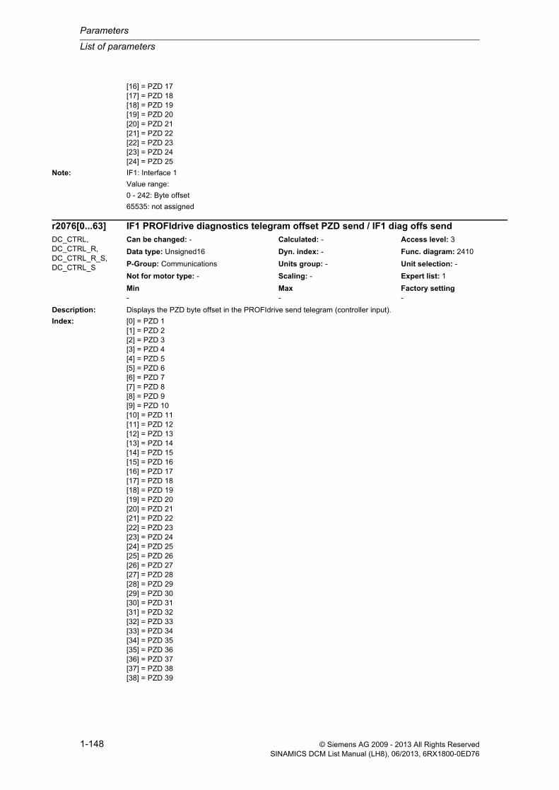
Parameters
List of parameters
1-148 © Siemens AG 2009 - 2013 All Rights ReservedSINAMICS DCM List Manual (LH8), 06/2013, 6RX1800-0ED76
[16] = PZD 17[17] = PZD 18[18] = PZD 19[19] = PZD 20[20] = PZD 21[21] = PZD 22[22] = PZD 23[23] = PZD 24[24] = PZD 25
Note: IF1: Interface 1
Value range:
0 - 242: Byte offset
65535: not assigned
Description: Displays the PZD byte offset in the PROFIdrive send telegram (controller input).
Index: [0] = PZD 1[1] = PZD 2[2] = PZD 3[3] = PZD 4[4] = PZD 5[5] = PZD 6[6] = PZD 7[7] = PZD 8[8] = PZD 9[9] = PZD 10[10] = PZD 11[11] = PZD 12[12] = PZD 13[13] = PZD 14[14] = PZD 15[15] = PZD 16[16] = PZD 17[17] = PZD 18[18] = PZD 19[19] = PZD 20[20] = PZD 21[21] = PZD 22[22] = PZD 23[23] = PZD 24[24] = PZD 25[25] = PZD 26[26] = PZD 27[27] = PZD 28[28] = PZD 29[29] = PZD 30[30] = PZD 31[31] = PZD 32[32] = PZD 33[33] = PZD 34[34] = PZD 35[35] = PZD 36[36] = PZD 37[37] = PZD 38[38] = PZD 39
r2076[0...63] IF1 PROFIdrive diagnostics telegram offset PZD send / IF1 diag offs sendDC_CTRL, DC_CTRL_R, DC_CTRL_R_S, DC_CTRL_S
Can be changed: - Calculated: - Access level: 3
Data type: Unsigned16 Dyn. index: - Func. diagram: 2410
P-Group: Communications Units group: - Unit selection: -
Not for motor type: - Scaling: - Expert list: 1
Min Max Factory setting - - -
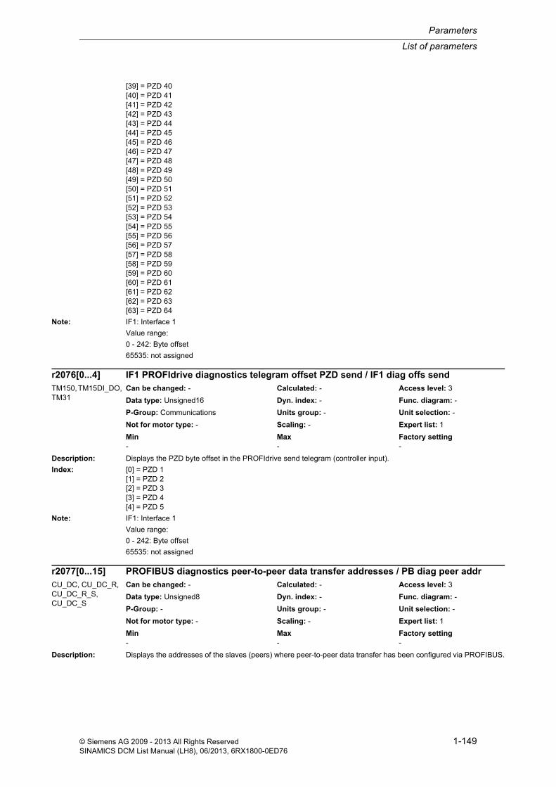
List of parameters
Parameters
1-149© Siemens AG 2009 - 2013 All Rights ReservedSINAMICS DCM List Manual (LH8), 06/2013, 6RX1800-0ED76
[39] = PZD 40[40] = PZD 41[41] = PZD 42[42] = PZD 43[43] = PZD 44[44] = PZD 45[45] = PZD 46[46] = PZD 47[47] = PZD 48[48] = PZD 49[49] = PZD 50[50] = PZD 51[51] = PZD 52[52] = PZD 53[53] = PZD 54[54] = PZD 55[55] = PZD 56[56] = PZD 57[57] = PZD 58[58] = PZD 59[59] = PZD 60[60] = PZD 61[61] = PZD 62[62] = PZD 63[63] = PZD 64
Note: IF1: Interface 1
Value range:
0 - 242: Byte offset
65535: not assigned
Description: Displays the PZD byte offset in the PROFIdrive send telegram (controller input).
Index: [0] = PZD 1[1] = PZD 2[2] = PZD 3[3] = PZD 4[4] = PZD 5
Note: IF1: Interface 1
Value range:
0 - 242: Byte offset
65535: not assigned
Description: Displays the addresses of the slaves (peers) where peer-to-peer data transfer has been configured via PROFIBUS.
r2076[0...4] IF1 PROFIdrive diagnostics telegram offset PZD send / IF1 diag offs sendTM150, TM15DI_DO, TM31
Can be changed: - Calculated: - Access level: 3
Data type: Unsigned16 Dyn. index: - Func. diagram: -
P-Group: Communications Units group: - Unit selection: -
Not for motor type: - Scaling: - Expert list: 1
Min Max Factory setting - - -
r2077[0...15] PROFIBUS diagnostics peer-to-peer data transfer addresses / PB diag peer addrCU_DC, CU_DC_R, CU_DC_R_S, CU_DC_S
Can be changed: - Calculated: - Access level: 3
Data type: Unsigned8 Dyn. index: - Func. diagram: -
P-Group: - Units group: - Unit selection: -
Not for motor type: - Scaling: - Expert list: 1
Min Max Factory setting - - -

Parameters
List of parameters
1-150 © Siemens AG 2009 - 2013 All Rights ReservedSINAMICS DCM List Manual (LH8), 06/2013, 6RX1800-0ED76
Description: Sets the send and receive telegram.
Contrary to p0922, a telegram can be selected using p2079 and subsequently expanded.
Value: 390: SIEMENS telegram 390, PZD-2/2999: Free telegram configuration with BICO
Note: For p0922 < 999 the following applies:
p2079 has the same value and is inhibited. All of the interconnections and extensions contained in the telegram are inhibited.
For p0922 = 999 the following applies:
p2079 can be freely set. If p2079 is also set to 999, then all of the interconnections can be set.
For p0922 = 999 and p2079 < 999 the following applies:
The interconnections contained in the telegram are inhibited. However, the telegram can be extended.
Description: Sets the send and receive telegram.
Contrary to p0922, a telegram can be selected using p2079 and subsequently expanded.
Value: 1: Standard telegram 1, PZD-2/23: Standard telegram 3, PZD-5/94: Standard telegram 4, PZD-6/1420: Standard telegram 20, PZD-2/6220: SIEMENS telegram 220, PZD-10/10352: SIEMENS telegram 352, PZD-6/6999: Free telegram configuration with BICO
Dependency: Refer to: p0922
Note: For p0922 < 999 the following applies:
p2079 has the same value and is inhibited. All of the interconnections and extensions contained in the telegram are inhibited.
For p0922 = 999 the following applies:
p2079 can be freely set. If p2079 is also set to 999, then all of the interconnections can be set.
For p0922 = 999 and p2079 < 999 the following applies:
The interconnections contained in the telegram are inhibited. However, the telegram can be extended.
Description: Selects bits to be sent to the PROFIdrive controller.
The individual bits are combined to form status word 1.
p2079 IF1 PROFIdrive PZD telegram selection extended / IF1 PZD telegr extCU_DC, CU_DC_R, CU_DC_R_S, CU_DC_S
Can be changed: T Calculated: - Access level: 3
Data type: Integer16 Dyn. index: - Func. diagram: -
P-Group: Communications Units group: - Unit selection: -
Not for motor type: - Scaling: - Expert list: 1
Min Max Factory setting 390 999 999
p2079 IF1 PROFIdrive PZD telegram selection extended / IF1 PZD telegr extDC_CTRL, DC_CTRL_R, DC_CTRL_R_S, DC_CTRL_S
Can be changed: T Calculated: - Access level: 3
Data type: Integer16 Dyn. index: - Func. diagram: -
P-Group: Communications Units group: - Unit selection: -
Not for motor type: - Scaling: - Expert list: 1
Min Max Factory setting 1 999 999
p2080[0...15] BI: Binector-connector converter status word 1 / Bin/con ZSW1All objects Can be changed: U, T Calculated: - Access level: 3
Data type: Unsigned32 / Binary Dyn. index: - Func. diagram: 2472
P-Group: Communications Units group: - Unit selection: -
Not for motor type: - Scaling: - Expert list: 1
Min Max Factory setting - - 0

List of parameters
Parameters
1-151© Siemens AG 2009 - 2013 All Rights ReservedSINAMICS DCM List Manual (LH8), 06/2013, 6RX1800-0ED76
Index: [0] = Bit 0[1] = Bit 1[2] = Bit 2[3] = Bit 3[4] = Bit 4[5] = Bit 5[6] = Bit 6[7] = Bit 7[8] = Bit 8[9] = Bit 9[10] = Bit 10[11] = Bit 11[12] = Bit 12[13] = Bit 13[14] = Bit 14[15] = Bit 15
Dependency: Refer to: p2088, r2089
Notice: The parameter may be protected as a result of p0922 or p2079 and cannot be changed.
Description: Selects bits to be sent to the PROFIdrive controller.
The individual bits are combined to form status word 2.
Index: [0] = Bit 0[1] = Bit 1[2] = Bit 2[3] = Bit 3[4] = Bit 4[5] = Bit 5[6] = Bit 6[7] = Bit 7[8] = Bit 8[9] = Bit 9[10] = Bit 10[11] = Bit 11[12] = Bit 12[13] = Bit 13[14] = Bit 14[15] = Bit 15
Dependency: Refer to: p2088, r2089
Notice: The parameter may be protected as a result of p0922 or p2079 and cannot be changed.
Note: For clock synchronous operation, bit 12 to 15 to transfer the sign-of-life are reserved in status word 2 - and may not be freely interconnected.
Description: Selects bits to be sent to the PROFIdrive controller.
The individual bits are combined to form free status word 3.
p2081[0...15] BI: Binector-connector converter status word 2 / Bin/con ZSW2All objects Can be changed: U, T Calculated: - Access level: 3
Data type: Unsigned32 / Binary Dyn. index: - Func. diagram: 2472
P-Group: Communications Units group: - Unit selection: -
Not for motor type: - Scaling: - Expert list: 1
Min Max Factory setting - - 0
p2082[0...15] BI: Binector-connector converter status word 3 / Bin/con ZSW3All objects Can be changed: U, T Calculated: - Access level: 3
Data type: Unsigned32 / Binary Dyn. index: - Func. diagram: 2472
P-Group: Communications Units group: - Unit selection: -
Not for motor type: - Scaling: - Expert list: 1
Min Max Factory setting - - 0

Parameters
List of parameters
1-152 © Siemens AG 2009 - 2013 All Rights ReservedSINAMICS DCM List Manual (LH8), 06/2013, 6RX1800-0ED76
Index: [0] = Bit 0[1] = Bit 1[2] = Bit 2[3] = Bit 3[4] = Bit 4[5] = Bit 5[6] = Bit 6[7] = Bit 7[8] = Bit 8[9] = Bit 9[10] = Bit 10[11] = Bit 11[12] = Bit 12[13] = Bit 13[14] = Bit 14[15] = Bit 15
Dependency: Refer to: p2088, r2089
Notice: The parameter may be protected as a result of p0922 or p2079 and cannot be changed.
Description: Selects bits to be sent to the PROFIdrive controller.
The individual bits are combined to form free status word 4.
Index: [0] = Bit 0[1] = Bit 1[2] = Bit 2[3] = Bit 3[4] = Bit 4[5] = Bit 5[6] = Bit 6[7] = Bit 7[8] = Bit 8[9] = Bit 9[10] = Bit 10[11] = Bit 11[12] = Bit 12[13] = Bit 13[14] = Bit 14[15] = Bit 15
Dependency: Refer to: p2088, r2089
Description: Selects bits to be sent to the PROFIdrive controller.
The individual bits are combined to form free status word 5.
Index: [0] = Bit 0[1] = Bit 1[2] = Bit 2
p2083[0...15] BI: Binector-connector converter status word 4 / Bin/con ZSW4All objects Can be changed: U, T Calculated: - Access level: 3
Data type: Unsigned32 / Binary Dyn. index: - Func. diagram: 2472
P-Group: Communications Units group: - Unit selection: -
Not for motor type: - Scaling: - Expert list: 1
Min Max Factory setting - - 0
p2084[0...15] BI: Binector-connector converter status word 5 / Bin/con ZSW5All objects Can be changed: U, T Calculated: - Access level: 3
Data type: Unsigned32 / Binary Dyn. index: - Func. diagram: 2472
P-Group: Communications Units group: - Unit selection: -
Not for motor type: - Scaling: - Expert list: 1
Min Max Factory setting - - 0

List of parameters
Parameters
1-153© Siemens AG 2009 - 2013 All Rights ReservedSINAMICS DCM List Manual (LH8), 06/2013, 6RX1800-0ED76
[3] = Bit 3[4] = Bit 4[5] = Bit 5[6] = Bit 6[7] = Bit 7[8] = Bit 8[9] = Bit 9[10] = Bit 10[11] = Bit 11[12] = Bit 12[13] = Bit 13[14] = Bit 14[15] = Bit 15
Dependency: Refer to: p2088, r2089
Description: Setting to invert the individual binector inputs of the binector connector converter.
Index: [0] = Status word 1[1] = Status word 2[2] = Free status word 3[3] = Free status word 4[4] = Free status word 5
Dependency: Refer to: p2080, p2081, p2082, p2083, r2089
Description: Connector output to interconnect the status words to a PZD send word.
Index: [0] = Status word 1[1] = Status word 2[2] = Free status word 3
p2088[0...4] Invert binector-connector converter status word / Bin/con ZSW invAll objects Can be changed: U, T Calculated: - Access level: 3
Data type: Unsigned16 Dyn. index: - Func. diagram: 2472
P-Group: Communications Units group: - Unit selection: -
Not for motor type: - Scaling: - Expert list: 1
Min Max Factory setting - - 0000 0000 0000 0000 bin
Bit field: Bit Signal name 1 signal 0 signal FP00 Bit 0 Inverted Not inverted -01 Bit 1 Inverted Not inverted -02 Bit 2 Inverted Not inverted -03 Bit 3 Inverted Not inverted -04 Bit 4 Inverted Not inverted -05 Bit 5 Inverted Not inverted -06 Bit 6 Inverted Not inverted -07 Bit 7 Inverted Not inverted -08 Bit 8 Inverted Not inverted -09 Bit 9 Inverted Not inverted -10 Bit 10 Inverted Not inverted -11 Bit 11 Inverted Not inverted -12 Bit 12 Inverted Not inverted -13 Bit 13 Inverted Not inverted -14 Bit 14 Inverted Not inverted -15 Bit 15 Inverted Not inverted -
r2089[0...4] CO: Send binector-connector converter status word / Bin/con ZSW sendAll objects Can be changed: - Calculated: - Access level: 3
Data type: Unsigned16 Dyn. index: - Func. diagram: 2472
P-Group: Communications Units group: - Unit selection: -
Not for motor type: - Scaling: - Expert list: 1
Min Max Factory setting - - -

Parameters
List of parameters
1-154 © Siemens AG 2009 - 2013 All Rights ReservedSINAMICS DCM List Manual (LH8), 06/2013, 6RX1800-0ED76
[3] = Free status word 4[4] = Free status word 5
Dependency: Refer to: p2051, p2080, p2081, p2082, p2083
Note: r2089 together with p2080 to p2084 forms five binector-connector converters.
Description: Binector output for bit-serial interconnection of PZD1 (normally control word 1) received from the PROFIdrive con-troller.
Note: IF1: Interface 1
Bit field: Bit Signal name 1 signal 0 signal FP00 Bit 0 ON OFF -01 Bit 1 ON OFF -02 Bit 2 ON OFF -03 Bit 3 ON OFF -04 Bit 4 ON OFF -05 Bit 5 ON OFF -06 Bit 6 ON OFF -07 Bit 7 ON OFF -08 Bit 8 ON OFF -09 Bit 9 ON OFF -10 Bit 10 ON OFF -11 Bit 11 ON OFF -12 Bit 12 ON OFF -13 Bit 13 ON OFF -14 Bit 14 ON OFF -15 Bit 15 ON OFF -
r2090.0...15 BO: IF1 PROFIBUS PZD1 receive bit-serial / IF1 PZD1 recv bitwCU_DC, CU_DC_R, CU_DC_R_S, CU_DC_S, DC_CTRL, DC_CTRL_R, DC_CTRL_R_S, DC_CTRL_S
Can be changed: - Calculated: - Access level: 3
Data type: Unsigned16 Dyn. index: - Func. diagram: 2440, 2460, 2481
P-Group: Communications Units group: - Unit selection: -
Not for motor type: - Scaling: - Expert list: 1
Min Max Factory setting - - -
Bit field: Bit Signal name 1 signal 0 signal FP00 Bit 0 ON OFF -01 Bit 1 ON OFF -02 Bit 2 ON OFF -03 Bit 3 ON OFF -04 Bit 4 ON OFF -05 Bit 5 ON OFF -06 Bit 6 ON OFF -07 Bit 7 ON OFF -08 Bit 8 ON OFF -09 Bit 9 ON OFF -10 Bit 10 ON OFF -11 Bit 11 ON OFF -12 Bit 12 ON OFF -13 Bit 13 ON OFF -14 Bit 14 ON OFF -15 Bit 15 ON OFF -
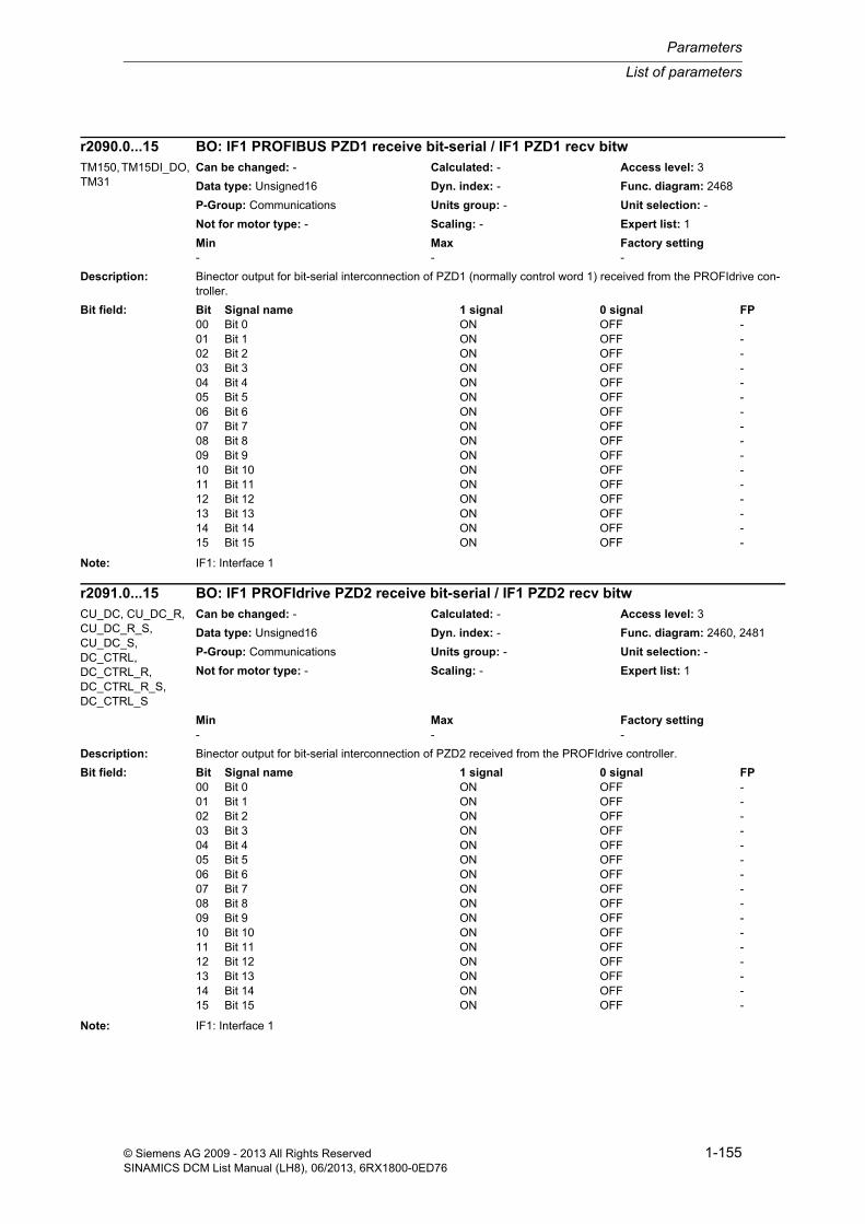
List of parameters
Parameters
1-155© Siemens AG 2009 - 2013 All Rights ReservedSINAMICS DCM List Manual (LH8), 06/2013, 6RX1800-0ED76
Description: Binector output for bit-serial interconnection of PZD1 (normally control word 1) received from the PROFIdrive con-troller.
Note: IF1: Interface 1
Description: Binector output for bit-serial interconnection of PZD2 received from the PROFIdrive controller.
Note: IF1: Interface 1
r2090.0...15 BO: IF1 PROFIBUS PZD1 receive bit-serial / IF1 PZD1 recv bitwTM150, TM15DI_DO, TM31
Can be changed: - Calculated: - Access level: 3
Data type: Unsigned16 Dyn. index: - Func. diagram: 2468
P-Group: Communications Units group: - Unit selection: -
Not for motor type: - Scaling: - Expert list: 1
Min Max Factory setting - - -
Bit field: Bit Signal name 1 signal 0 signal FP00 Bit 0 ON OFF -01 Bit 1 ON OFF -02 Bit 2 ON OFF -03 Bit 3 ON OFF -04 Bit 4 ON OFF -05 Bit 5 ON OFF -06 Bit 6 ON OFF -07 Bit 7 ON OFF -08 Bit 8 ON OFF -09 Bit 9 ON OFF -10 Bit 10 ON OFF -11 Bit 11 ON OFF -12 Bit 12 ON OFF -13 Bit 13 ON OFF -14 Bit 14 ON OFF -15 Bit 15 ON OFF -
r2091.0...15 BO: IF1 PROFIdrive PZD2 receive bit-serial / IF1 PZD2 recv bitwCU_DC, CU_DC_R, CU_DC_R_S, CU_DC_S, DC_CTRL, DC_CTRL_R, DC_CTRL_R_S, DC_CTRL_S
Can be changed: - Calculated: - Access level: 3
Data type: Unsigned16 Dyn. index: - Func. diagram: 2460, 2481
P-Group: Communications Units group: - Unit selection: -
Not for motor type: - Scaling: - Expert list: 1
Min Max Factory setting - - -
Bit field: Bit Signal name 1 signal 0 signal FP00 Bit 0 ON OFF -01 Bit 1 ON OFF -02 Bit 2 ON OFF -03 Bit 3 ON OFF -04 Bit 4 ON OFF -05 Bit 5 ON OFF -06 Bit 6 ON OFF -07 Bit 7 ON OFF -08 Bit 8 ON OFF -09 Bit 9 ON OFF -10 Bit 10 ON OFF -11 Bit 11 ON OFF -12 Bit 12 ON OFF -13 Bit 13 ON OFF -14 Bit 14 ON OFF -15 Bit 15 ON OFF -

Parameters
List of parameters
1-156 © Siemens AG 2009 - 2013 All Rights ReservedSINAMICS DCM List Manual (LH8), 06/2013, 6RX1800-0ED76
Description: Binector output for bit-serial interconnection of PZD2 received from the PROFIdrive controller.
Note: IF1: Interface 1
Description: Binector output for bit-serial interconnection of PZD3 received from the PROFIdrive controller.
Note: IF1: Interface 1
r2091.0...15 BO: IF1 PROFIdrive PZD2 receive bit-serial / IF1 PZD2 recv bitwTM150, TM15DI_DO, TM31
Can be changed: - Calculated: - Access level: 3
Data type: Unsigned16 Dyn. index: - Func. diagram: 2468
P-Group: Communications Units group: - Unit selection: -
Not for motor type: - Scaling: - Expert list: 1
Min Max Factory setting - - -
Bit field: Bit Signal name 1 signal 0 signal FP00 Bit 0 ON OFF -01 Bit 1 ON OFF -02 Bit 2 ON OFF -03 Bit 3 ON OFF -04 Bit 4 ON OFF -05 Bit 5 ON OFF -06 Bit 6 ON OFF -07 Bit 7 ON OFF -08 Bit 8 ON OFF -09 Bit 9 ON OFF -10 Bit 10 ON OFF -11 Bit 11 ON OFF -12 Bit 12 ON OFF -13 Bit 13 ON OFF -14 Bit 14 ON OFF -15 Bit 15 ON OFF -
r2092.0...15 BO: IF1 PROFIdrive PZD3 receive bit-serial / IF1 PZD3 recv bitwCU_DC, CU_DC_R, CU_DC_R_S, CU_DC_S
Can be changed: - Calculated: - Access level: 3
Data type: Unsigned16 Dyn. index: - Func. diagram: 2468
P-Group: Communications Units group: - Unit selection: -
Not for motor type: - Scaling: - Expert list: 1
Min Max Factory setting - - -
Bit field: Bit Signal name 1 signal 0 signal FP00 Bit 0 ON OFF -01 Bit 1 ON OFF -02 Bit 2 ON OFF -03 Bit 3 ON OFF -04 Bit 4 ON OFF -05 Bit 5 ON OFF -06 Bit 6 ON OFF -07 Bit 7 ON OFF -08 Bit 8 ON OFF -09 Bit 9 ON OFF -10 Bit 10 ON OFF -11 Bit 11 ON OFF -12 Bit 12 ON OFF -13 Bit 13 ON OFF -14 Bit 14 ON OFF -15 Bit 15 ON OFF -
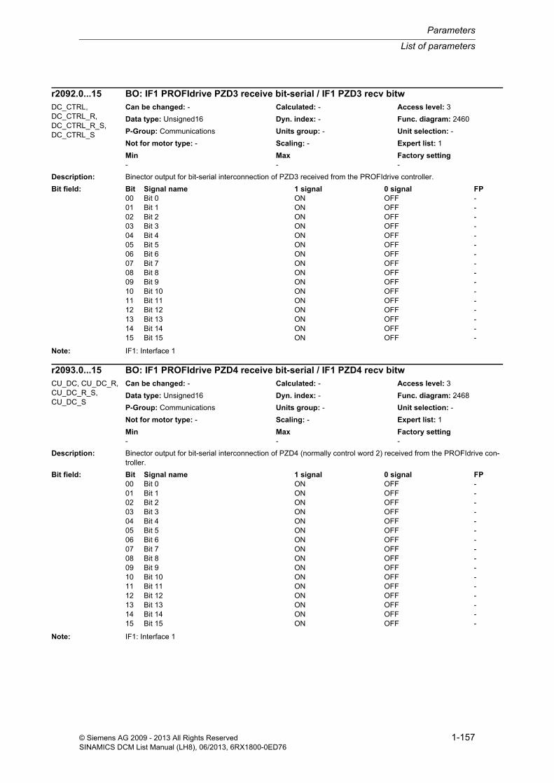
List of parameters
Parameters
1-157© Siemens AG 2009 - 2013 All Rights ReservedSINAMICS DCM List Manual (LH8), 06/2013, 6RX1800-0ED76
Description: Binector output for bit-serial interconnection of PZD3 received from the PROFIdrive controller.
Note: IF1: Interface 1
Description: Binector output for bit-serial interconnection of PZD4 (normally control word 2) received from the PROFIdrive con-troller.
Note: IF1: Interface 1
r2092.0...15 BO: IF1 PROFIdrive PZD3 receive bit-serial / IF1 PZD3 recv bitwDC_CTRL, DC_CTRL_R, DC_CTRL_R_S, DC_CTRL_S
Can be changed: - Calculated: - Access level: 3
Data type: Unsigned16 Dyn. index: - Func. diagram: 2460
P-Group: Communications Units group: - Unit selection: -
Not for motor type: - Scaling: - Expert list: 1
Min Max Factory setting - - -
Bit field: Bit Signal name 1 signal 0 signal FP00 Bit 0 ON OFF -01 Bit 1 ON OFF -02 Bit 2 ON OFF -03 Bit 3 ON OFF -04 Bit 4 ON OFF -05 Bit 5 ON OFF -06 Bit 6 ON OFF -07 Bit 7 ON OFF -08 Bit 8 ON OFF -09 Bit 9 ON OFF -10 Bit 10 ON OFF -11 Bit 11 ON OFF -12 Bit 12 ON OFF -13 Bit 13 ON OFF -14 Bit 14 ON OFF -15 Bit 15 ON OFF -
r2093.0...15 BO: IF1 PROFIdrive PZD4 receive bit-serial / IF1 PZD4 recv bitwCU_DC, CU_DC_R, CU_DC_R_S, CU_DC_S
Can be changed: - Calculated: - Access level: 3
Data type: Unsigned16 Dyn. index: - Func. diagram: 2468
P-Group: Communications Units group: - Unit selection: -
Not for motor type: - Scaling: - Expert list: 1
Min Max Factory setting - - -
Bit field: Bit Signal name 1 signal 0 signal FP00 Bit 0 ON OFF -01 Bit 1 ON OFF -02 Bit 2 ON OFF -03 Bit 3 ON OFF -04 Bit 4 ON OFF -05 Bit 5 ON OFF -06 Bit 6 ON OFF -07 Bit 7 ON OFF -08 Bit 8 ON OFF -09 Bit 9 ON OFF -10 Bit 10 ON OFF -11 Bit 11 ON OFF -12 Bit 12 ON OFF -13 Bit 13 ON OFF -14 Bit 14 ON OFF -15 Bit 15 ON OFF -

Parameters
List of parameters
1-158 © Siemens AG 2009 - 2013 All Rights ReservedSINAMICS DCM List Manual (LH8), 06/2013, 6RX1800-0ED76
Description: Binector output for bit-serial interconnection of PZD4 (normally control word 2) received from the PROFIdrive con-troller.
Note: IF1: Interface 1
Description: Binector output for bit-serial onward interconnection of a PZD word received from the PROFIdrive controller.
The PZD is selected via p2099[0].
Dependency: Refer to: p2099
r2093.0...15 BO: IF1 PROFIdrive PZD4 receive bit-serial / IF1 PZD4 recv bitwDC_CTRL, DC_CTRL_R, DC_CTRL_R_S, DC_CTRL_S
Can be changed: - Calculated: - Access level: 3
Data type: Unsigned16 Dyn. index: - Func. diagram: 2460
P-Group: Communications Units group: - Unit selection: -
Not for motor type: - Scaling: - Expert list: 1
Min Max Factory setting - - -
Bit field: Bit Signal name 1 signal 0 signal FP00 Bit 0 ON OFF -01 Bit 1 ON OFF -02 Bit 2 ON OFF -03 Bit 3 ON OFF -04 Bit 4 ON OFF -05 Bit 5 ON OFF -06 Bit 6 ON OFF -07 Bit 7 ON OFF -08 Bit 8 ON OFF -09 Bit 9 ON OFF -10 Bit 10 ON OFF -11 Bit 11 ON OFF -12 Bit 12 ON OFF -13 Bit 13 ON OFF -14 Bit 14 ON OFF -15 Bit 15 ON OFF -
r2094.0...15 BO: Connector-binector converter binector output / Con/bin outpCU_DC, CU_DC_R, CU_DC_R_S, CU_DC_S, DC_CTRL, DC_CTRL_R, DC_CTRL_R_S, DC_CTRL_S
Can be changed: - Calculated: - Access level: 3
Data type: Unsigned16 Dyn. index: - Func. diagram: 2460, 2481
P-Group: Communications Units group: - Unit selection: -
Not for motor type: - Scaling: - Expert list: 1
Min Max Factory setting - - -
Bit field: Bit Signal name 1 signal 0 signal FP00 Bit 0 ON OFF -01 Bit 1 ON OFF -02 Bit 2 ON OFF -03 Bit 3 ON OFF -04 Bit 4 ON OFF -05 Bit 5 ON OFF -06 Bit 6 ON OFF -07 Bit 7 ON OFF -08 Bit 8 ON OFF -09 Bit 9 ON OFF -10 Bit 10 ON OFF -11 Bit 11 ON OFF -12 Bit 12 ON OFF -13 Bit 13 ON OFF -14 Bit 14 ON OFF -15 Bit 15 ON OFF -

List of parameters
Parameters
1-159© Siemens AG 2009 - 2013 All Rights ReservedSINAMICS DCM List Manual (LH8), 06/2013, 6RX1800-0ED76
Description: Binector output for bit-serial onward interconnection of a PZD word received from the PROFIdrive controller.
The PZD is selected via p2099[0].
Dependency: Refer to: p2099
Description: Binector output for bit-serial interconnection of a PZD word received from the PROFIdrive controller.
The PZD is selected via p2099[1].
Dependency: Refer to: p2099
r2094.0...15 BO: Connector-binector converter binector output / Con/bin outpTM150, TM15DI_DO, TM31
Can be changed: - Calculated: - Access level: 3
Data type: Unsigned16 Dyn. index: - Func. diagram: 2468
P-Group: Communications Units group: - Unit selection: -
Not for motor type: - Scaling: - Expert list: 1
Min Max Factory setting - - -
Bit field: Bit Signal name 1 signal 0 signal FP00 Bit 0 ON OFF -01 Bit 1 ON OFF -02 Bit 2 ON OFF -03 Bit 3 ON OFF -04 Bit 4 ON OFF -05 Bit 5 ON OFF -06 Bit 6 ON OFF -07 Bit 7 ON OFF -08 Bit 8 ON OFF -09 Bit 9 ON OFF -10 Bit 10 ON OFF -11 Bit 11 ON OFF -12 Bit 12 ON OFF -13 Bit 13 ON OFF -14 Bit 14 ON OFF -15 Bit 15 ON OFF -
r2095.0...15 BO: Connector-binector converter binector output / Con/bin outpCU_DC, CU_DC_R, CU_DC_R_S, CU_DC_S, DC_CTRL, DC_CTRL_R, DC_CTRL_R_S, DC_CTRL_S
Can be changed: - Calculated: - Access level: 3
Data type: Unsigned16 Dyn. index: - Func. diagram: 2440, 2460, 2481
P-Group: Communications Units group: - Unit selection: -
Not for motor type: - Scaling: - Expert list: 1
Min Max Factory setting - - -
Bit field: Bit Signal name 1 signal 0 signal FP00 Bit 0 ON OFF -01 Bit 1 ON OFF -02 Bit 2 ON OFF -03 Bit 3 ON OFF -04 Bit 4 ON OFF -05 Bit 5 ON OFF -06 Bit 6 ON OFF -07 Bit 7 ON OFF -08 Bit 8 ON OFF -09 Bit 9 ON OFF -10 Bit 10 ON OFF -11 Bit 11 ON OFF -12 Bit 12 ON OFF -13 Bit 13 ON OFF -14 Bit 14 ON OFF -15 Bit 15 ON OFF -

Parameters
List of parameters
1-160 © Siemens AG 2009 - 2013 All Rights ReservedSINAMICS DCM List Manual (LH8), 06/2013, 6RX1800-0ED76
Description: Binector output for bit-serial interconnection of a PZD word received from the PROFIdrive controller.
The PZD is selected via p2099[1].
Dependency: Refer to: p2099
Description: Setting to invert the individual binector outputs of the connector-binector converter.
Using p2098[0], the signals of CI: p2099[0] are influenced.
Using p2098[1], the signals of CI: p2099[1] are influenced.
r2095.0...15 BO: Connector-binector converter binector output / Con/bin outpTM150, TM15DI_DO, TM31
Can be changed: - Calculated: - Access level: 3
Data type: Unsigned16 Dyn. index: - Func. diagram: 2468
P-Group: Communications Units group: - Unit selection: -
Not for motor type: - Scaling: - Expert list: 1
Min Max Factory setting - - -
Bit field: Bit Signal name 1 signal 0 signal FP00 Bit 0 ON OFF -01 Bit 1 ON OFF -02 Bit 2 ON OFF -03 Bit 3 ON OFF -04 Bit 4 ON OFF -05 Bit 5 ON OFF -06 Bit 6 ON OFF -07 Bit 7 ON OFF -08 Bit 8 ON OFF -09 Bit 9 ON OFF -10 Bit 10 ON OFF -11 Bit 11 ON OFF -12 Bit 12 ON OFF -13 Bit 13 ON OFF -14 Bit 14 ON OFF -15 Bit 15 ON OFF -
p2098[0...1] Inverter connector-binector converter binector output / Con/bin outp invCU_DC, CU_DC_R, CU_DC_R_S, CU_DC_S, DC_CTRL, DC_CTRL_R, DC_CTRL_R_S, DC_CTRL_S
Can be changed: U, T Calculated: - Access level: 3
Data type: Unsigned16 Dyn. index: - Func. diagram: 2460, 2481
P-Group: Communications Units group: - Unit selection: -
Not for motor type: - Scaling: - Expert list: 1
Min Max Factory setting - - 0000 0000 0000 0000 bin
Bit field: Bit Signal name 1 signal 0 signal FP00 Bit 0 Inverted Not inverted -01 Bit 1 Inverted Not inverted -02 Bit 2 Inverted Not inverted -03 Bit 3 Inverted Not inverted -04 Bit 4 Inverted Not inverted -05 Bit 5 Inverted Not inverted -06 Bit 6 Inverted Not inverted -07 Bit 7 Inverted Not inverted -08 Bit 8 Inverted Not inverted -09 Bit 9 Inverted Not inverted -10 Bit 10 Inverted Not inverted -11 Bit 11 Inverted Not inverted -12 Bit 12 Inverted Not inverted -13 Bit 13 Inverted Not inverted -14 Bit 14 Inverted Not inverted -15 Bit 15 Inverted Not inverted -

List of parameters
Parameters
1-161© Siemens AG 2009 - 2013 All Rights ReservedSINAMICS DCM List Manual (LH8), 06/2013, 6RX1800-0ED76
Dependency: Refer to: r2094, r2095, p2099
Description: Setting to invert the individual binector outputs of the connector-binector converter.
Using p2098[0], the signals of CI: p2099[0] are influenced.
Using p2098[1], the signals of CI: p2099[1] are influenced.
Dependency: Refer to: r2094, r2095, p2099
Description: Sets the signal source for the connector-binector converter.
A PZD receive word can be selected as signal source. The signals are available to be serially passed-on (intercon-nection).
Dependency: Refer to: r2094, r2095
Note: From the signal source set via the connector input, the corresponding lower 16 bits are converted.
p2099[0...1] together with r2094.0...15 and r2095.0...15 forms two connector-binector converters:
Connector input p2099[0] to binector output in r2094.0...15
Connector input p2099[1] to binector output in r2095.0...15
p2098[0...1] Inverter connector-binector converter binector output / Con/bin outp invTM150, TM15DI_DO, TM31
Can be changed: U, T Calculated: - Access level: 3
Data type: Unsigned16 Dyn. index: - Func. diagram: 2468
P-Group: Communications Units group: - Unit selection: -
Not for motor type: - Scaling: - Expert list: 1
Min Max Factory setting - - 0000 0000 0000 0000 bin
Bit field: Bit Signal name 1 signal 0 signal FP00 Bit 0 Inverted Not inverted -01 Bit 1 Inverted Not inverted -02 Bit 2 Inverted Not inverted -03 Bit 3 Inverted Not inverted -04 Bit 4 Inverted Not inverted -05 Bit 5 Inverted Not inverted -06 Bit 6 Inverted Not inverted -07 Bit 7 Inverted Not inverted -08 Bit 8 Inverted Not inverted -09 Bit 9 Inverted Not inverted -10 Bit 10 Inverted Not inverted -11 Bit 11 Inverted Not inverted -12 Bit 12 Inverted Not inverted -13 Bit 13 Inverted Not inverted -14 Bit 14 Inverted Not inverted -15 Bit 15 Inverted Not inverted -
p2099[0...1] CI: Connector-binector converter signal source / Con/bin S_srcCU_DC, CU_DC_R, CU_DC_R_S, CU_DC_S, DC_CTRL, DC_CTRL_R, DC_CTRL_R_S, DC_CTRL_S
Can be changed: U, T Calculated: - Access level: 3
Data type: Unsigned32 / Integer16 Dyn. index: - Func. diagram: 2460, 2481
P-Group: Communications Units group: - Unit selection: -
Not for motor type: - Scaling: - Expert list: 1
Min Max Factory setting - - 0

Parameters
List of parameters
1-162 © Siemens AG 2009 - 2013 All Rights ReservedSINAMICS DCM List Manual (LH8), 06/2013, 6RX1800-0ED76
Description: Sets the signal source for the connector-binector converter.
A PZD receive word can be selected as signal source. The signals are available to be serially passed-on (intercon-nection).
Dependency: Refer to: r2094, r2095
Note: From the signal source set via the connector input, the corresponding lower 16 bits are converted.
p2099[0...1] together with r2094.0...15 and r2095.0...15 forms two connector-binector converters:
Connector input p2099[0] to binector output in r2094.0...15
Connector input p2099[1] to binector output in r2095.0...15
Description: Selects the faults for which the fault response should be changed
Dependency: The fault is selected and the required response is set under the same index.
Refer to: p2101
Notice: For the following cases, it is not possible to re-parameterize the fault response to a fault:
- if there is no existing fault number.
- the message type is not "fault" (F).
Note: Re-parameterization is also possible if a fault is present. The change only becomes effective after the fault has been resolved.
p2099[0...1] CI: Connector-binector converter signal source / Con/bin S_srcTM150, TM15DI_DO, TM31
Can be changed: U, T Calculated: - Access level: 3
Data type: Unsigned32 / Integer16 Dyn. index: - Func. diagram: 2468
P-Group: Communications Units group: - Unit selection: -
Not for motor type: - Scaling: - Expert list: 1
Min Max Factory setting - - 0
p2100[0...19] Setting the fault number for fault response / F_no F responseCU_DC, CU_DC_R, CU_DC_R_S, CU_DC_S, DC_CTRL, DC_CTRL_R, DC_CTRL_R_S, DC_CTRL_S
Can be changed: U, T Calculated: - Access level: 3
Data type: Unsigned16 Dyn. index: - Func. diagram: 8075
P-Group: Messages Units group: - Unit selection: -
Not for motor type: - Scaling: - Expert list: 1
Min Max Factory setting 0 65535 0
p2100[0...19] Setting the fault number for fault response / F_no F responseTM150, TM15DI_DO, TM31
Can be changed: U, T Calculated: - Access level: 3
Data type: Unsigned16 Dyn. index: - Func. diagram: 1750, 8075
P-Group: Messages Units group: - Unit selection: -
Not for motor type: - Scaling: - Expert list: 1
Min Max Factory setting 0 65535 0

List of parameters
Parameters
1-163© Siemens AG 2009 - 2013 All Rights ReservedSINAMICS DCM List Manual (LH8), 06/2013, 6RX1800-0ED76
Description: Sets the fault response for the selected fault.
Value: 0: NONE
Dependency: The fault is selected and the required response is set under the same index.
Note: Re-parameterization is also possible if a fault is present. The change only becomes effective after the fault has been resolved.
Description: Sets the fault response for the selected fault.
Value: 0: NONE1: OFF12: OFF23: OFF34: Reserved5: Reserved6: Reserved7: Reserved
Dependency: The fault is selected and the required response is set under the same index.
Refer to: p2100
Note: Re-parameterization is also possible if a fault is present. The change only becomes effective after the fault has been resolved.
The fault response can only be changed for faults with the appropriate identification (see the List Manual, chapter "Faults and alarms").
Example:
F12345 and fault response = OFF3 (OFF1, OFF2, NONE)
--> The default fault response OFF3 can be changed to OFF1, OFF2 or NONE.
Re value = 1 (OFF1):
Braking along the ramp-function generator down ramp followed by a pulse inhibit.
Re value = 2 (OFF2):
Internal/external pulse inhibit.
Re value = 3 (OFF3):
Braking along the OFF3 down ramp followed by a pulse inhibit.
Parameter values designated as "reserved", act just like the value = 2 (OFF2)
p2101[0...19] Setting the fault response / Fault responseCU_DC, CU_DC_R, CU_DC_R_S, CU_DC_S
Can be changed: U, T Calculated: - Access level: 3
Data type: Integer16 Dyn. index: - Func. diagram: 8075
P-Group: Messages Units group: - Unit selection: -
Not for motor type: - Scaling: - Expert list: 1
Min Max Factory setting 0 0 0
p2101[0...19] Setting the fault response / Fault responseDC_CTRL, DC_CTRL_R, DC_CTRL_R_S, DC_CTRL_S
Can be changed: U, T Calculated: - Access level: 3
Data type: Integer16 Dyn. index: - Func. diagram: 8075
P-Group: Messages Units group: - Unit selection: -
Not for motor type: - Scaling: - Expert list: 1
Min Max Factory setting 0 7 0

Parameters
List of parameters
1-164 © Siemens AG 2009 - 2013 All Rights ReservedSINAMICS DCM List Manual (LH8), 06/2013, 6RX1800-0ED76
Description: Sets the fault response for the selected fault.
Value: 0: NONE
Dependency: The fault is selected and the required response is set under the same index.
Note: Re-parameterization is also possible if a fault is present. The change only becomes effective after the fault has been resolved.
Description: Sets the signal source to acknowledge all faults at all drive objects of the drive system.
Note: A fault acknowledgement is triggered with a 0/1 signal.
Description: Sets the first signal source to acknowledge faults.
Notice: The parameter may be protected as a result of p0922 or p2079 and cannot be changed.
Note: A fault acknowledgement is triggered with a 0/1 signal.
Description: Sets the first signal source to acknowledge faults.
Notice: The parameter may be protected as a result of p0922 or p2079 and cannot be changed.
Note: A fault acknowledgement is triggered with a 0/1 signal.
p2101[0...19] Setting the fault response / Fault responseTM150, TM15DI_DO, TM31
Can be changed: U, T Calculated: - Access level: 3
Data type: Integer16 Dyn. index: - Func. diagram: 1750, 8075
P-Group: Messages Units group: - Unit selection: -
Not for motor type: - Scaling: - Expert list: 1
Min Max Factory setting 0 0 0
p2102 BI: Acknowledge all faults / Ackn all faultsCU_DC, CU_DC_R, CU_DC_R_S, CU_DC_S
Can be changed: U, T Calculated: - Access level: 3
Data type: Unsigned32 / Binary Dyn. index: - Func. diagram: 2546, 8060
P-Group: Messages Units group: - Unit selection: -
Not for motor type: - Scaling: - Expert list: 1
Min Max Factory setting - - 0
p2103 BI: 1. Acknowledge faults / 1. AcknowledgeCU_DC, CU_DC_R, CU_DC_R_S, CU_DC_S, TM150, TM15DI_DO, TM31
Can be changed: U, T Calculated: - Access level: 3
Data type: Unsigned32 / Binary Dyn. index: - Func. diagram: -
P-Group: Messages Units group: - Unit selection: -
Not for motor type: - Scaling: - Expert list: 1
Min Max Factory setting - - 0
p2103[0...n] BI: 1. Acknowledge faults / 1. AcknowledgeDC_CTRL, DC_CTRL_R, DC_CTRL_R_S, DC_CTRL_S
Can be changed: U, T Calculated: - Access level: 3
Data type: Unsigned32 / Binary Dyn. index: CDS, p0170 Func. diagram: 2546
P-Group: Messages Units group: - Unit selection: -
Not for motor type: - Scaling: - Expert list: 1
Min Max Factory setting - - 0

List of parameters
Parameters
1-165© Siemens AG 2009 - 2013 All Rights ReservedSINAMICS DCM List Manual (LH8), 06/2013, 6RX1800-0ED76
Description: Sets the second signal source to acknowledge faults.
Note: A fault acknowledgement is triggered with a 0/1 signal.
Description: Sets the second signal source to acknowledge faults.
Note: A fault acknowledgement is triggered with a 0/1 signal.
Description: Sets the third signal source to acknowledge faults.
Note: A fault acknowledgement is triggered with a 0/1 signal.
Description: Sets the third signal source to acknowledge faults.
Note: A fault acknowledgement is triggered with a 0/1 signal.
Description: Sets the signal source for external fault 1.
Note: An external fault is triggered with a 1/0 signal.
If this fault is output at the Control Unit, then it is transferred to all existing drive objects.
p2104 BI: 2. Acknowledge faults / 2. AcknowledgeCU_DC, CU_DC_R, CU_DC_R_S, CU_DC_S, TM150, TM15DI_DO, TM31
Can be changed: U, T Calculated: - Access level: 3
Data type: Unsigned32 / Binary Dyn. index: - Func. diagram: -
P-Group: Messages Units group: - Unit selection: -
Not for motor type: - Scaling: - Expert list: 1
Min Max Factory setting - - 0
p2104[0...n] BI: 2. Acknowledge faults / 2. AcknowledgeDC_CTRL, DC_CTRL_R, DC_CTRL_R_S, DC_CTRL_S
Can be changed: U, T Calculated: - Access level: 3
Data type: Unsigned32 / Binary Dyn. index: CDS, p0170 Func. diagram: 2546
P-Group: Messages Units group: - Unit selection: -
Not for motor type: - Scaling: - Expert list: 1
Min Max Factory setting - - 0
p2105 BI: 3. Acknowledge faults / 3. AcknowledgeCU_DC, CU_DC_R, CU_DC_R_S, CU_DC_S, TM150, TM15DI_DO, TM31
Can be changed: U, T Calculated: - Access level: 3
Data type: Unsigned32 / Binary Dyn. index: - Func. diagram: -
P-Group: Messages Units group: - Unit selection: -
Not for motor type: - Scaling: - Expert list: 1
Min Max Factory setting - - 0
p2105[0...n] BI: 3. Acknowledge faults / 3. AcknowledgeDC_CTRL, DC_CTRL_R, DC_CTRL_R_S, DC_CTRL_S
Can be changed: U, T Calculated: - Access level: 3
Data type: Unsigned32 / Binary Dyn. index: CDS, p0170 Func. diagram: 2546
P-Group: Messages Units group: - Unit selection: -
Not for motor type: - Scaling: - Expert list: 1
Min Max Factory setting - - 0
p2106 BI: External fault 1 / External fault 1CU_DC, CU_DC_R, CU_DC_R_S, CU_DC_S, TM150, TM15DI_DO, TM31
Can be changed: U, T Calculated: - Access level: 3
Data type: Unsigned32 / Binary Dyn. index: - Func. diagram: -
P-Group: Messages Units group: - Unit selection: -
Not for motor type: - Scaling: - Expert list: 1
Min Max Factory setting - - 1

Parameters
List of parameters
1-166 © Siemens AG 2009 - 2013 All Rights ReservedSINAMICS DCM List Manual (LH8), 06/2013, 6RX1800-0ED76
Description: Sets the signal source for external fault 1.
Note: An external fault is triggered with a 1/0 signal.
If this fault is output at the Control Unit, then it is transferred to all existing drive objects.
Description: Sets the signal source for external fault 2.
Note: An external fault is triggered with a 1/0 signal.
If this fault is output at the Control Unit, then it is transferred to all existing drive objects.
Description: Sets the signal source for external fault 2.
Note: An external fault is triggered with a 1/0 signal.
If this fault is output at the Control Unit, then it is transferred to all existing drive objects.
Description: Sets the signal source for external fault 3.
External fault 3 is initiated by the following AND logic operation:
- BI: p2108 negated
- BI: p3111
- BI: p3112 negated
Dependency: Refer to: p3110, p3111, p3112
Note: An external fault is triggered with a 1/0 signal.
If this fault is output at the Control Unit, then it is transferred to all existing drive objects.
p2106[0...n] BI: External fault 1 / External fault 1DC_CTRL, DC_CTRL_R, DC_CTRL_R_S, DC_CTRL_S
Can be changed: U, T Calculated: - Access level: 3
Data type: Unsigned32 / Binary Dyn. index: CDS, p0170 Func. diagram: 2546
P-Group: Messages Units group: - Unit selection: -
Not for motor type: - Scaling: - Expert list: 1
Min Max Factory setting - - 1
p2107 BI: External fault 2 / External fault 2CU_DC, CU_DC_R, CU_DC_R_S, CU_DC_S, TM150, TM15DI_DO, TM31
Can be changed: U, T Calculated: - Access level: 3
Data type: Unsigned32 / Binary Dyn. index: - Func. diagram: -
P-Group: Messages Units group: - Unit selection: -
Not for motor type: - Scaling: - Expert list: 1
Min Max Factory setting - - 1
p2107[0...n] BI: External fault 2 / External fault 2DC_CTRL, DC_CTRL_R, DC_CTRL_R_S, DC_CTRL_S
Can be changed: U, T Calculated: - Access level: 3
Data type: Unsigned32 / Binary Dyn. index: CDS, p0170 Func. diagram: 2546
P-Group: Messages Units group: - Unit selection: -
Not for motor type: - Scaling: - Expert list: 1
Min Max Factory setting - - 1
p2108 BI: External fault 3 / External fault 3CU_DC, CU_DC_R, CU_DC_R_S, CU_DC_S, TM150, TM15DI_DO, TM31
Can be changed: U, T Calculated: - Access level: 3
Data type: Unsigned32 / Binary Dyn. index: - Func. diagram: -
P-Group: Messages Units group: - Unit selection: -
Not for motor type: - Scaling: - Expert list: 1
Min Max Factory setting - - 1

List of parameters
Parameters
1-167© Siemens AG 2009 - 2013 All Rights ReservedSINAMICS DCM List Manual (LH8), 06/2013, 6RX1800-0ED76
Description: Sets the signal source for external fault 3.
External fault 3 is initiated by the following AND logic operation:
- BI: p2108 negated
- BI: p3111
- BI: p3112 negated
Dependency: Refer to: p3110, p3111, p3112
Note: An external fault is triggered with a 1/0 signal.
If this fault is output at the Control Unit, then it is transferred to all existing drive objects.
Description: Displays the system runtime in milliseconds when the fault was removed.
Dependency: Refer to: r0945, r0947, r0948, r0949, r2114, r2130, r2133, r2136, r3115, r3120, r3122
Notice: The time comprises r2136 (days) and r2109 (milliseconds).
Note: The buffer parameters are cyclically updated in the background (refer to status signal in r2139).
The structure of the fault buffer and the assignment of the indices is shown in r0945.
Description: This parameter is identical to r2122.
p2108[0...n] BI: External fault 3 / External fault 3DC_CTRL, DC_CTRL_R, DC_CTRL_R_S, DC_CTRL_S
Can be changed: U, T Calculated: - Access level: 3
Data type: Unsigned32 / Binary Dyn. index: CDS, p0170 Func. diagram: 2546
P-Group: Messages Units group: - Unit selection: -
Not for motor type: - Scaling: - Expert list: 1
Min Max Factory setting - - 1
r2109[0...63] Fault time removed in milliseconds / t_flt resolved msCU_DC, CU_DC_R, CU_DC_R_S, CU_DC_S, TM150, TM15DI_DO, TM31
Can be changed: - Calculated: - Access level: 3
Data type: Unsigned32 Dyn. index: - Func. diagram: 1750, 8060
P-Group: Messages Units group: - Unit selection: -
Not for motor type: - Scaling: - Expert list: 1
Min Max Factory setting - [ms] - [ms] - [ms]
r2109[0...63] Fault time removed in milliseconds / t_flt resolved msDC_CTRL, DC_CTRL_R, DC_CTRL_R_S, DC_CTRL_S
Can be changed: - Calculated: - Access level: 3
Data type: Unsigned32 Dyn. index: - Func. diagram: 8060
P-Group: Messages Units group: - Unit selection: -
Not for motor type: - Scaling: - Expert list: 1
Min Max Factory setting - [ms] - [ms] - [ms]
r2110[0...63] Alarm number / Alarm numberAll objects Can be changed: - Calculated: - Access level: 2
Data type: Unsigned16 Dyn. index: - Func. diagram: 8065
P-Group: Messages Units group: - Unit selection: -
Not for motor type: - Scaling: - Expert list: 1
Min Max Factory setting - - -

Parameters
List of parameters
1-168 © Siemens AG 2009 - 2013 All Rights ReservedSINAMICS DCM List Manual (LH8), 06/2013, 6RX1800-0ED76
Description: Number of alarms that have occurred after the last reset.
Dependency: When p2111 is set to 0, the following is initiated:
- all of the alarms of the alarm buffer that have gone [0...7] are transferred into the alarm history [8...63].
- the alarm buffer [0...7] is deleted.
Refer to: r2110, r2122, r2123, r2124, r2125
Note: The parameter is reset to 0 at POWER ON.
Description: Sets the signal source for external alarm 1.
Note: An external alarm is triggered with a 1/0 signal.
Description: Sets the signal source for external alarm 1.
Note: An external alarm is triggered with a 1/0 signal.
p2111 Alarm counter / Alarm counterCU_DC, CU_DC_R, CU_DC_R_S, CU_DC_S, DC_CTRL, DC_CTRL_R, DC_CTRL_R_S, DC_CTRL_S
Can be changed: U, T Calculated: - Access level: 3
Data type: Unsigned16 Dyn. index: - Func. diagram: 8065
P-Group: Messages Units group: - Unit selection: -
Not for motor type: - Scaling: - Expert list: 1
Min Max Factory setting 0 65535 0
p2111 Alarm counter / Alarm counterTM150, TM15DI_DO, TM31
Can be changed: U, T Calculated: - Access level: 3
Data type: Unsigned16 Dyn. index: - Func. diagram: 1750, 8065
P-Group: Messages Units group: - Unit selection: -
Not for motor type: - Scaling: - Expert list: 1
Min Max Factory setting 0 65535 0
p2112 BI: External alarm 1 / External alarm 1CU_DC, CU_DC_R, CU_DC_R_S, CU_DC_S, TM150, TM15DI_DO, TM31
Can be changed: U, T Calculated: - Access level: 3
Data type: Unsigned32 / Binary Dyn. index: - Func. diagram: -
P-Group: Messages Units group: - Unit selection: -
Not for motor type: - Scaling: - Expert list: 1
Min Max Factory setting - - 1
p2112[0...n] BI: External alarm 1 / External alarm 1DC_CTRL, DC_CTRL_R, DC_CTRL_R_S, DC_CTRL_S
Can be changed: U, T Calculated: - Access level: 3
Data type: Unsigned32 / Binary Dyn. index: CDS, p0170 Func. diagram: 2546
P-Group: Messages Units group: - Unit selection: -
Not for motor type: - Scaling: - Expert list: 1
Min Max Factory setting - - 1

List of parameters
Parameters
1-169© Siemens AG 2009 - 2013 All Rights ReservedSINAMICS DCM List Manual (LH8), 06/2013, 6RX1800-0ED76
Description: Displays the total system runtime for the drive unit.
The time comprises r2114[0] (milliseconds) and r2114[1] (days).
After r2114[0] has reached a value of 86.400.000 ms (24 hours) this value is reset and r2114[1] is incremented.
Index: [0] = Milliseconds[1] = Days
Dependency: Refer to: r0948, r2109, r2123, r2125, r2130, r2136, r2145, r2146
Note: The time in r2114 is used to display the times for faults and alarms.
When the electronic power supply is switched out, the counter values are saved.
After the drive unit is powered up, the counter continues to run with the last value that was saved.
Description: Sets the signal source for external alarm 2.
Note: An external alarm is triggered with a 1/0 signal.
Description: Sets the signal source for external alarm 2.
Note: An external alarm is triggered with a 1/0 signal.
Description: Sets the signal source for external alarm 3.
Note: An external alarm is triggered with a 1/0 signal.
r2114[0...1] System runtime total / Sys runtime totCU_DC, CU_DC_R, CU_DC_R_S, CU_DC_S
Can be changed: - Calculated: - Access level: 3
Data type: Unsigned32 Dyn. index: - Func. diagram: -
P-Group: Messages Units group: - Unit selection: -
Not for motor type: - Scaling: - Expert list: 1
Min Max Factory setting - - -
p2116 BI: External alarm 2 / External alarm 2CU_DC, CU_DC_R, CU_DC_R_S, CU_DC_S, TM150, TM15DI_DO, TM31
Can be changed: U, T Calculated: - Access level: 3
Data type: Unsigned32 / Binary Dyn. index: - Func. diagram: -
P-Group: Messages Units group: - Unit selection: -
Not for motor type: - Scaling: - Expert list: 1
Min Max Factory setting - - 1
p2116[0...n] BI: External alarm 2 / External alarm 2DC_CTRL, DC_CTRL_R, DC_CTRL_R_S, DC_CTRL_S
Can be changed: U, T Calculated: - Access level: 3
Data type: Unsigned32 / Binary Dyn. index: CDS, p0170 Func. diagram: 2546
P-Group: Messages Units group: - Unit selection: -
Not for motor type: - Scaling: - Expert list: 1
Min Max Factory setting - - 1
p2117 BI: External alarm 3 / External alarm 3CU_DC, CU_DC_R, CU_DC_R_S, CU_DC_S, TM150, TM15DI_DO, TM31
Can be changed: U, T Calculated: - Access level: 3
Data type: Unsigned32 / Binary Dyn. index: - Func. diagram: -
P-Group: Messages Units group: - Unit selection: -
Not for motor type: - Scaling: - Expert list: 1
Min Max Factory setting - - 1

Parameters
List of parameters
1-170 © Siemens AG 2009 - 2013 All Rights ReservedSINAMICS DCM List Manual (LH8), 06/2013, 6RX1800-0ED76
Description: Sets the signal source for external alarm 3.
Note: An external alarm is triggered with a 1/0 signal.
Description: Selects faults or alarms for which the message type should be changed.
Dependency: Selects the fault or alarm selection and sets the required type of message realized under the same index.
Refer to: p2119
Notice: It is not possible to re-parameterize the message type in the following cases:
- if there is no existing message number.
Note: Re-parameterization is also possible if a message is present. The change only becomes effective after the mes-sage has gone.
Description: Sets the message type for the selected fault or alarm.
p2117[0...n] BI: External alarm 3 / External alarm 3DC_CTRL, DC_CTRL_R, DC_CTRL_R_S, DC_CTRL_S
Can be changed: U, T Calculated: - Access level: 3
Data type: Unsigned32 / Binary Dyn. index: CDS, p0170 Func. diagram: 2546
P-Group: Messages Units group: - Unit selection: -
Not for motor type: - Scaling: - Expert list: 1
Min Max Factory setting - - 1
p2118[0...19] Sets the message number for message type. / Msg_no Msg_typeCU_DC, CU_DC_R, CU_DC_R_S, CU_DC_S, TM150, TM15DI_DO, TM31
Can be changed: U, T Calculated: - Access level: 3
Data type: Unsigned16 Dyn. index: - Func. diagram: 1750, 8075
P-Group: Messages Units group: - Unit selection: -
Not for motor type: - Scaling: - Expert list: 1
Min Max Factory setting 0 65535 0
p2118[0...19] Sets the message number for message type. / Msg_no Msg_typeDC_CTRL, DC_CTRL_R, DC_CTRL_R_S, DC_CTRL_S
Can be changed: U, T Calculated: - Access level: 3
Data type: Unsigned16 Dyn. index: - Func. diagram: 8075
P-Group: Messages Units group: - Unit selection: -
Not for motor type: - Scaling: - Expert list: 1
Min Max Factory setting 0 65535 0
p2119[0...19] Setting the message type / Message typeCU_DC, CU_DC_R, CU_DC_R_S, CU_DC_S, DC_CTRL, DC_CTRL_R, DC_CTRL_R_S, DC_CTRL_S
Can be changed: U, T Calculated: - Access level: 3
Data type: Integer16 Dyn. index: - Func. diagram: 8075
P-Group: Messages Units group: - Unit selection: -
Not for motor type: - Scaling: - Expert list: 1
Min Max Factory setting 1 3 1

List of parameters
Parameters
1-171© Siemens AG 2009 - 2013 All Rights ReservedSINAMICS DCM List Manual (LH8), 06/2013, 6RX1800-0ED76
Value: 1: Fault (F)2: Alarm (A)3: No message (N)
Dependency: Selects the fault or alarm selection and sets the required type of message realized under the same index.
Refer to: p2118
Note: Re-parameterization is also possible if a message is present. The change only becomes effective after the mes-sage has gone.
The message type can only be changed for messages with the appropriate identification.
Example:
F12345(A) --> Fault F12345 can be changed to alarm A12345.
In this case, the message number that may be possibly entered in p2100[0...19] and p2126[0...19] is automatically removed.
Description: Sets the message type for the selected fault or alarm.
Value: 1: Fault (F)2: Alarm (A)3: No message (N)
Dependency: Selects the fault or alarm selection and sets the required type of message realized under the same index.
Refer to: p2118
Note: Re-parameterization is also possible if a message is present. The change only becomes effective after the mes-sage has gone.
The message type can only be changed for messages with the appropriate identification.
Example:
F12345(A) --> Fault F12345 can be changed to alarm A12345.
In this case, the message number that may be possibly entered in p2100[0...19] and p2126[0...19] is automatically removed.
Description: Displays the sum of all of the fault and alarm buffer changes in the drive unit.
Dependency: Refer to: r0944, r2121
Description: This counter is incremented every time the alarm buffer changes.
Dependency: Refer to: r2110, r2122, r2123, r2124, r2125
p2119[0...19] Setting the message type / Message typeTM150, TM15DI_DO, TM31
Can be changed: U, T Calculated: - Access level: 3
Data type: Integer16 Dyn. index: - Func. diagram: 1750, 8075
P-Group: Messages Units group: - Unit selection: -
Not for motor type: - Scaling: - Expert list: 1
Min Max Factory setting 1 3 1
r2120 CO: Sum of fault and alarm buffer changes / Sum buffer changedAll objects Can be changed: - Calculated: - Access level: 4
Data type: Unsigned16 Dyn. index: - Func. diagram: 8065
P-Group: Messages Units group: - Unit selection: -
Not for motor type: - Scaling: - Expert list: 1
Min Max Factory setting - - -
r2121 CO: Counter alarm buffer changes / Alrm buff changedAll objects Can be changed: - Calculated: - Access level: 3
Data type: Unsigned16 Dyn. index: - Func. diagram: 8065
P-Group: Messages Units group: - Unit selection: -
Not for motor type: - Scaling: - Expert list: 1
Min Max Factory setting - - -

Parameters
List of parameters
1-172 © Siemens AG 2009 - 2013 All Rights ReservedSINAMICS DCM List Manual (LH8), 06/2013, 6RX1800-0ED76
Description: Displays the number of alarms that have occurred.
Dependency: Refer to: r2110, r2123, r2124, r2125, r2134, r2145, r2146, r3121, r3123
Notice: The properties of the alarm buffer should be taken from the corresponding product documentation.
Note: The buffer parameters are cyclically updated in the background (refer to status signal in r2139).
Alarm buffer structure (general principle):
r2122[0], r2124[0], r2123[0], r2125[0] --> alarm 1 (the oldest)
. . .
r2122[7], r2124[7], r2123[7], r2125[7] --> Alarm 8 (the latest)
When the alarm buffer is full, the alarms that have gone are entered into the alarm history:
r2122[8], r2124[8], r2123[8], r2125[8] --> Alarm 1 (the latest)
. . .
r2122[63], r2124[63], r2123[63], r2125[63] --> alarm 56 (the oldest)
Description: Displays the system runtime in milliseconds when the alarm occurred.
r2122[0...63] Alarm code / Alarm codeCU_DC, CU_DC_R, CU_DC_R_S, CU_DC_S, DC_CTRL, DC_CTRL_R, DC_CTRL_R_S, DC_CTRL_S
Can be changed: - Calculated: - Access level: 2
Data type: Unsigned16 Dyn. index: - Func. diagram: 8065
P-Group: Messages Units group: - Unit selection: -
Not for motor type: - Scaling: - Expert list: 1
Min Max Factory setting - - -
r2122[0...63] Alarm code / Alarm codeTM150, TM15DI_DO, TM31
Can be changed: - Calculated: - Access level: 2
Data type: Unsigned16 Dyn. index: - Func. diagram: 1750, 8065
P-Group: Messages Units group: - Unit selection: -
Not for motor type: - Scaling: - Expert list: 1
Min Max Factory setting - - -
r2123[0...63] Alarm time received in milliseconds / t_alarm recv msCU_DC, CU_DC_R, CU_DC_R_S, CU_DC_S, DC_CTRL, DC_CTRL_R, DC_CTRL_R_S, DC_CTRL_S
Can be changed: - Calculated: - Access level: 3
Data type: Unsigned32 Dyn. index: - Func. diagram: 8065
P-Group: Messages Units group: - Unit selection: -
Not for motor type: - Scaling: - Expert list: 1
Min Max Factory setting - [ms] - [ms] - [ms]

List of parameters
Parameters
1-173© Siemens AG 2009 - 2013 All Rights ReservedSINAMICS DCM List Manual (LH8), 06/2013, 6RX1800-0ED76
Dependency: Refer to: r2110, r2114, r2122, r2124, r2125, r2134, r2145, r2146, r3121, r3123
Notice: The time comprises r2145 (days) and r2123 (milliseconds).
Note: The buffer parameters are cyclically updated in the background (refer to status signal in r2139).
The structure of the alarm buffer and the assignment of the indices is shown in r2122.
Description: Displays the system runtime in milliseconds when the alarm occurred.
Dependency: Refer to: r2110, r2114, r2122, r2124, r2125, r2134, r2145, r2146, r3121, r3123
Notice: The time comprises r2145 (days) and r2123 (milliseconds).
Note: The buffer parameters are cyclically updated in the background (refer to status signal in r2139).
The structure of the alarm buffer and the assignment of the indices is shown in r2122.
Description: Displays additional information about the active alarm (as integer number).
Dependency: Refer to: r2110, r2122, r2123, r2125, r2134, r2145, r2146, r3121, r3123
Note: The buffer parameters are cyclically updated in the background (refer to status signal in r2139).
The structure of the alarm buffer and the assignment of the indices is shown in r2122.
r2123[0...63] Alarm time received in milliseconds / t_alarm recv msTM150, TM15DI_DO, TM31
Can be changed: - Calculated: - Access level: 3
Data type: Unsigned32 Dyn. index: - Func. diagram: 1750, 8065
P-Group: Messages Units group: - Unit selection: -
Not for motor type: - Scaling: - Expert list: 1
Min Max Factory setting - [ms] - [ms] - [ms]
r2124[0...63] Alarm value / Alarm valueCU_DC, CU_DC_R, CU_DC_R_S, CU_DC_S, DC_CTRL, DC_CTRL_R, DC_CTRL_R_S, DC_CTRL_S
Can be changed: - Calculated: - Access level: 3
Data type: Integer32 Dyn. index: - Func. diagram: 8065
P-Group: Messages Units group: - Unit selection: -
Not for motor type: - Scaling: - Expert list: 1
Min Max Factory setting - - -
r2124[0...63] Alarm value / Alarm valueTM150, TM15DI_DO, TM31
Can be changed: - Calculated: - Access level: 3
Data type: Integer32 Dyn. index: - Func. diagram: 1750, 8065
P-Group: Messages Units group: - Unit selection: -
Not for motor type: - Scaling: - Expert list: 1
Min Max Factory setting - - -

Parameters
List of parameters
1-174 © Siemens AG 2009 - 2013 All Rights ReservedSINAMICS DCM List Manual (LH8), 06/2013, 6RX1800-0ED76
Description: Displays the system runtime in milliseconds when the alarm was cleared.
Dependency: Refer to: r2110, r2114, r2122, r2123, r2124, r2134, r2145, r2146, r3121, r3123
Notice: The time comprises r2146 (days) and r2125 (milliseconds).
Note: The buffer parameters are cyclically updated in the background (refer to status signal in r2139).
The structure of the alarm buffer and the assignment of the indices is shown in r2122.
Description: Selects the faults for which the acknowledge mode is to be changed
Dependency: Selects the faults and sets the required acknowledge mode realized under the same index
Refer to: p2127
Notice: It is not possible to re-parameterize the acknowledge mode of a fault in the following cases:
- Fault number does not exist.
- Message type is not "fault" (F).
Note: Re-parameterization is also possible if a fault is present. The change only becomes effective after the fault has been resolved.
r2125[0...63] Alarm time removed in milliseconds / t_alarm res msCU_DC, CU_DC_R, CU_DC_R_S, CU_DC_S, DC_CTRL, DC_CTRL_R, DC_CTRL_R_S, DC_CTRL_S
Can be changed: - Calculated: - Access level: 3
Data type: Unsigned32 Dyn. index: - Func. diagram: 8065
P-Group: Messages Units group: - Unit selection: -
Not for motor type: - Scaling: - Expert list: 1
Min Max Factory setting - [ms] - [ms] - [ms]
r2125[0...63] Alarm time removed in milliseconds / t_alarm res msTM150, TM15DI_DO, TM31
Can be changed: - Calculated: - Access level: 3
Data type: Unsigned32 Dyn. index: - Func. diagram: 1750, 8065
P-Group: Messages Units group: - Unit selection: -
Not for motor type: - Scaling: - Expert list: 1
Min Max Factory setting - [ms] - [ms] - [ms]
p2126[0...19] Setting fault number for acknowledge mode / Fault_no ackn_modeCU_DC, CU_DC_R, CU_DC_R_S, CU_DC_S, DC_CTRL, DC_CTRL_R, DC_CTRL_R_S, DC_CTRL_S
Can be changed: U, T Calculated: - Access level: 3
Data type: Unsigned16 Dyn. index: - Func. diagram: 8075
P-Group: Messages Units group: - Unit selection: -
Not for motor type: - Scaling: - Expert list: 1
Min Max Factory setting 0 65535 0

List of parameters
Parameters
1-175© Siemens AG 2009 - 2013 All Rights ReservedSINAMICS DCM List Manual (LH8), 06/2013, 6RX1800-0ED76
Description: Selects the faults for which the acknowledge mode is to be changed
Dependency: Selects the faults and sets the required acknowledge mode realized under the same index
Refer to: p2127
Notice: It is not possible to re-parameterize the acknowledge mode of a fault in the following cases:
- Fault number does not exist.
- Message type is not "fault" (F).
Note: Re-parameterization is also possible if a fault is present. The change only becomes effective after the fault has been resolved.
Description: Sets the acknowledge mode for selected fault.
Value: 1: Acknowledgment only using POWER ON2: Ack IMMEDIATELY after the fault cause has been removed3: Acknowledgement only for PULSE INHIBIT
Dependency: Selects the faults and sets the required acknowledge mode realized under the same index
Refer to: p2126
Notice: It is not possible to re-parameterize the acknowledge mode of a fault in the following cases:
- if there is no existing fault number.
- the message type is not "fault" (F).
Note: Re-parameterization is also possible if a fault is present. The change only becomes effective after the fault has been resolved.
The acknowledge mode can only be changed for faults with the appropriate identification.
Example:
F12345 and acknowledge mode = IMMEDIATELY (POWER ON)
--> The acknowledge mode can be changed from IMMEDIATELY to POWER ON.
Description: Sets the acknowledge mode for selected fault.
Value: 1: Acknowledgment only using POWER ON2: Ack IMMEDIATELY after the fault cause has been removed3: Acknowledgement only for PULSE INHIBIT
p2126[0...19] Setting fault number for acknowledge mode / Fault_no ackn_modeTM150, TM15DI_DO, TM31
Can be changed: U, T Calculated: - Access level: 3
Data type: Unsigned16 Dyn. index: - Func. diagram: 1750, 8075
P-Group: Messages Units group: - Unit selection: -
Not for motor type: - Scaling: - Expert list: 1
Min Max Factory setting 0 65535 0
p2127[0...19] Sets acknowledgement mode / Acknowledge modeCU_DC, CU_DC_R, CU_DC_R_S, CU_DC_S, DC_CTRL, DC_CTRL_R, DC_CTRL_R_S, DC_CTRL_S
Can be changed: U, T Calculated: - Access level: 3
Data type: Integer16 Dyn. index: - Func. diagram: 8075
P-Group: Messages Units group: - Unit selection: -
Not for motor type: - Scaling: - Expert list: 1
Min Max Factory setting 1 3 1
p2127[0...19] Sets acknowledgement mode / Acknowledge modeTM150, TM15DI_DO, TM31
Can be changed: U, T Calculated: - Access level: 3
Data type: Integer16 Dyn. index: - Func. diagram: 1750, 8075
P-Group: Messages Units group: - Unit selection: -
Not for motor type: - Scaling: - Expert list: 1
Min Max Factory setting 1 3 1

Parameters
List of parameters
1-176 © Siemens AG 2009 - 2013 All Rights ReservedSINAMICS DCM List Manual (LH8), 06/2013, 6RX1800-0ED76
Dependency: Selects the faults and sets the required acknowledge mode realized under the same index
Refer to: p2126
Notice: It is not possible to re-parameterize the acknowledge mode of a fault in the following cases:
- if there is no existing fault number.
- the message type is not "fault" (F).
Note: Re-parameterization is also possible if a fault is present. The change only becomes effective after the fault has been resolved.
The acknowledge mode can only be changed for faults with the appropriate identification.
Example:
F12345 and acknowledge mode = IMMEDIATELY (POWER ON)
--> The acknowledge mode can be changed from IMMEDIATELY to POWER ON.
Description: Selects faults or alarms which can be used as trigger.
Dependency: Refer to: r2129
Description: Selects faults or alarms which can be used as trigger.
Dependency: Refer to: r2129
Description: Trigger signal for the selected faults and alarms
p2128[0...15] Selecting fault/alarm code for trigger / Message triggerCU_DC, CU_DC_R, CU_DC_R_S, CU_DC_S, DC_CTRL, DC_CTRL_R, DC_CTRL_R_S, DC_CTRL_S
Can be changed: U, T Calculated: - Access level: 3
Data type: Unsigned16 Dyn. index: - Func. diagram: 8070
P-Group: Messages Units group: - Unit selection: -
Not for motor type: - Scaling: - Expert list: 1
Min Max Factory setting 0 65535 0
p2128[0...15] Selecting fault/alarm code for trigger / Message triggerTM150, TM15DI_DO, TM31
Can be changed: U, T Calculated: - Access level: 3
Data type: Unsigned16 Dyn. index: - Func. diagram: 1750, 8070
P-Group: Messages Units group: - Unit selection: -
Not for motor type: - Scaling: - Expert list: 1
Min Max Factory setting 0 65535 0
r2129.0...15 CO/BO: Trigger word for faults and alarms / Trigger wordCU_DC, CU_DC_R, CU_DC_R_S, CU_DC_S, DC_CTRL, DC_CTRL_R, DC_CTRL_R_S, DC_CTRL_S
Can be changed: - Calculated: - Access level: 3
Data type: Unsigned16 Dyn. index: - Func. diagram: 8070
P-Group: Messages Units group: - Unit selection: -
Not for motor type: - Scaling: - Expert list: 1
Min Max Factory setting - - -
Bit field: Bit Signal name 1 signal 0 signal FP00 Trigger signal p2128[0] ON OFF -01 Trigger signal p2128[1] ON OFF -02 Trigger signal p2128[2] ON OFF -03 Trigger signal p2128[3] ON OFF -04 Trigger signal p2128[4] ON OFF -05 Trigger signal p2128[5] ON OFF -06 Trigger signal p2128[6] ON OFF -07 Trigger signal p2128[7] ON OFF -08 Trigger signal p2128[8] ON OFF -09 Trigger signal p2128[9] ON OFF -

List of parameters
Parameters
1-177© Siemens AG 2009 - 2013 All Rights ReservedSINAMICS DCM List Manual (LH8), 06/2013, 6RX1800-0ED76
Dependency: If one of the faults or alarms selected in p2128[n] occurs, then the particular bit of this binector output is set.
Refer to: p2128
Note: CO: r2129 = 0 --> None of the selected messages has occurred.
CO: r2129 > 0 --> At least one of the selected messages has occurred.
Description: Trigger signal for the selected faults and alarms
Dependency: If one of the faults or alarms selected in p2128[n] occurs, then the particular bit of this binector output is set.
Refer to: p2128
Note: CO: r2129 = 0 --> None of the selected messages has occurred.
CO: r2129 > 0 --> At least one of the selected messages has occurred.
Description: Displays the system runtime in days when the fault occurred.
Dependency: Refer to: r0945, r0947, r0948, r0949, r2109, r2114, r2133, r2136, r3115, r3120, r3122
Notice: The time comprises r2130 (days) and r0948 (milliseconds).
Note: The buffer parameters are cyclically updated in the background (refer to status signal in r2139).
10 Trigger signal p2128[10] ON OFF -11 Trigger signal p2128[11] ON OFF -12 Trigger signal p2128[12] ON OFF -13 Trigger signal p2128[13] ON OFF -14 Trigger signal p2128[14] ON OFF -15 Trigger signal p2128[15] ON OFF -
r2129.0...15 CO/BO: Trigger word for faults and alarms / Trigger wordTM150, TM15DI_DO, TM31
Can be changed: - Calculated: - Access level: 3
Data type: Unsigned16 Dyn. index: - Func. diagram: 1530, 8070
P-Group: Messages Units group: - Unit selection: -
Not for motor type: - Scaling: - Expert list: 1
Min Max Factory setting - - -
Bit field: Bit Signal name 1 signal 0 signal FP00 Trigger signal p2128[0] ON OFF -01 Trigger signal p2128[1] ON OFF -02 Trigger signal p2128[2] ON OFF -03 Trigger signal p2128[3] ON OFF -04 Trigger signal p2128[4] ON OFF -05 Trigger signal p2128[5] ON OFF -06 Trigger signal p2128[6] ON OFF -07 Trigger signal p2128[7] ON OFF -08 Trigger signal p2128[8] ON OFF -09 Trigger signal p2128[9] ON OFF -10 Trigger signal p2128[10] ON OFF -11 Trigger signal p2128[11] ON OFF -12 Trigger signal p2128[12] ON OFF -13 Trigger signal p2128[13] ON OFF -14 Trigger signal p2128[14] ON OFF -15 Trigger signal p2128[15] ON OFF -
r2130[0...63] Fault time received in days / t_fault recv daysAll objects Can be changed: - Calculated: - Access level: 3
Data type: Unsigned16 Dyn. index: - Func. diagram: 8060
P-Group: Messages Units group: - Unit selection: -
Not for motor type: - Scaling: - Expert list: 1
Min Max Factory setting - - -

Parameters
List of parameters
1-178 © Siemens AG 2009 - 2013 All Rights ReservedSINAMICS DCM List Manual (LH8), 06/2013, 6RX1800-0ED76
Description: Displays the code of the oldest active fault.
Dependency: Refer to: r3131, r3132
Note: 0: No fault present.
Description: Displays the code of the last alarm that occurred.
Note: 0: No alarm present.
Description: Displays additional information about the fault that occurred for float values.
Dependency: Refer to: r0945, r0947, r0948, r0949, r2109, r2130, r2136, r3115
Note: The buffer parameters are cyclically updated in the background (refer to status signal in r2139).
Description: Displays additional information about the active alarm for float values.
Dependency: Refer to: r2110, r2122, r2123, r2124, r2125, r2145, r2146, r3121, r3123
Note: The buffer parameters are cyclically updated in the background (refer to status signal in r2139).
Description: Displays the second status word of faults and alarms.
r2131 CO: Actual fault code / Actual fault codeAll objects Can be changed: - Calculated: - Access level: 3
Data type: Unsigned16 Dyn. index: - Func. diagram: 8060
P-Group: Messages Units group: - Unit selection: -
Not for motor type: - Scaling: - Expert list: 1
Min Max Factory setting - - -
r2132 CO: Actual alarm code / Actual alarm codeAll objects Can be changed: - Calculated: - Access level: 3
Data type: Unsigned16 Dyn. index: - Func. diagram: 8065
P-Group: Messages Units group: - Unit selection: -
Not for motor type: - Scaling: - Expert list: 1
Min Max Factory setting - - -
r2133[0...63] Fault value for float values / Fault val floatAll objects Can be changed: - Calculated: - Access level: 3
Data type: FloatingPoint32 Dyn. index: - Func. diagram: 8060
P-Group: Messages Units group: - Unit selection: -
Not for motor type: - Scaling: - Expert list: 1
Min Max Factory setting - - -
r2134[0...63] Alarm value for float values / Alarm value floatAll objects Can be changed: - Calculated: - Access level: 3
Data type: FloatingPoint32 Dyn. index: - Func. diagram: 8065
P-Group: Messages Units group: - Unit selection: -
Not for motor type: - Scaling: - Expert list: 1
Min Max Factory setting - - -
r2135.0...2 CO/BO: Status word faults/alarms 2 / ZSW fault/alarm 2CU_DC, CU_DC_R, CU_DC_R_S, CU_DC_S
Can be changed: - Calculated: - Access level: 2
Data type: Unsigned16 Dyn. index: - Func. diagram: 2548
P-Group: Displays, signals Units group: - Unit selection: -
Not for motor type: - Scaling: - Expert list: 1
Min Max Factory setting - - -

List of parameters
Parameters
1-179© Siemens AG 2009 - 2013 All Rights ReservedSINAMICS DCM List Manual (LH8), 06/2013, 6RX1800-0ED76
Description: Displays the second status word of faults and alarms.
Description: Displays the second status word of faults and alarms.
Description: Displays the system runtime in days when the fault was removed.
Dependency: Refer to: r0945, r0947, r0948, r0949, r2109, r2114, r2130, r2133, r3115, r3120, r3122
Notice: The time comprises r2136 (days) and r2109 (milliseconds).
Note: The buffer parameters are cyclically updated in the background (refer to status signal in r2139).
Bit field: Bit Signal name 1 signal 0 signal FP00 Fault encoder 1 Yes No -01 Fault encoder 2 Yes No -02 Fault encoder 3 Yes No -
r2135.0...15 CO/BO: Status word faults/alarms 2 / ZSW fault/alarm 2DC_CTRL, DC_CTRL_R, DC_CTRL_R_S, DC_CTRL_S
Can be changed: - Calculated: - Access level: 2
Data type: Unsigned16 Dyn. index: - Func. diagram: 2548
P-Group: Displays, signals Units group: - Unit selection: -
Not for motor type: - Scaling: - Expert list: 1
Min Max Factory setting - - -
Bit field: Bit Signal name 1 signal 0 signal FP00 Fault encoder 1 Yes No -01 Fault encoder 2 Yes No -02 Fault encoder 3 Yes No -12 Fault motor overtemperature Yes No -13 Fault power unit thermal overload Yes No -14 Alarm motor overtemperature Yes No -15 Alarm power unit thermal overload Yes No -
r2135.0...15 CO/BO: Status word faults/alarms 2 / ZSW fault/alarm 2TM150, TM15DI_DO, TM31
Can be changed: - Calculated: - Access level: 2
Data type: Unsigned16 Dyn. index: - Func. diagram: 1530, 2548
P-Group: Displays, signals Units group: - Unit selection: -
Not for motor type: - Scaling: - Expert list: 1
Min Max Factory setting - - -
Bit field: Bit Signal name 1 signal 0 signal FP00 Fault encoder 1 Yes No -01 Fault encoder 2 Yes No -02 Fault encoder 3 Yes No -12 Fault motor overtemperature Yes No -13 Fault power unit thermal overload Yes No -14 Alarm motor overtemperature Yes No -15 Alarm power unit thermal overload Yes No -
r2136[0...63] Fault time removed in days / t_flt resolv. daysAll objects Can be changed: - Calculated: - Access level: 3
Data type: Unsigned16 Dyn. index: - Func. diagram: 8060
P-Group: Messages Units group: - Unit selection: -
Not for motor type: - Scaling: - Expert list: 1
Min Max Factory setting - - -
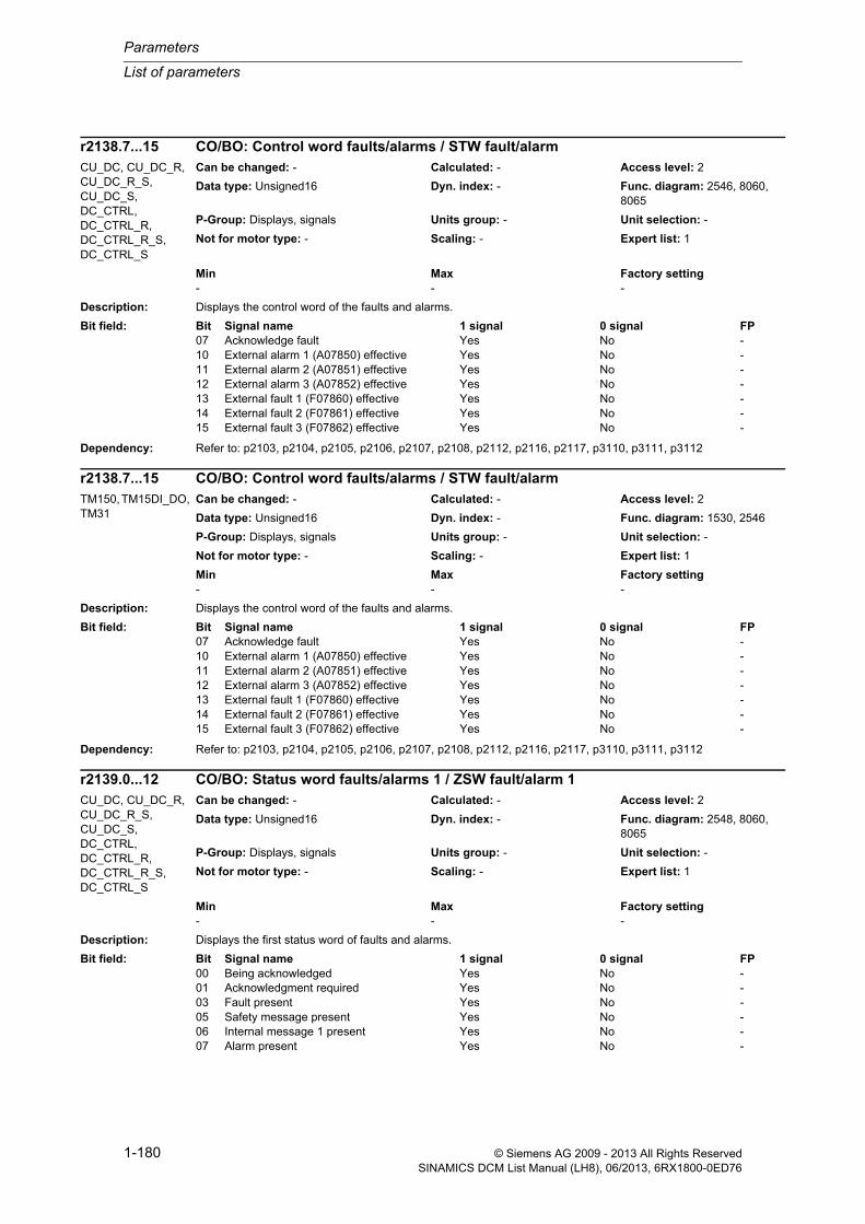
Parameters
List of parameters
1-180 © Siemens AG 2009 - 2013 All Rights ReservedSINAMICS DCM List Manual (LH8), 06/2013, 6RX1800-0ED76
Description: Displays the control word of the faults and alarms.
Dependency: Refer to: p2103, p2104, p2105, p2106, p2107, p2108, p2112, p2116, p2117, p3110, p3111, p3112
Description: Displays the control word of the faults and alarms.
Dependency: Refer to: p2103, p2104, p2105, p2106, p2107, p2108, p2112, p2116, p2117, p3110, p3111, p3112
Description: Displays the first status word of faults and alarms.
r2138.7...15 CO/BO: Control word faults/alarms / STW fault/alarmCU_DC, CU_DC_R, CU_DC_R_S, CU_DC_S, DC_CTRL, DC_CTRL_R, DC_CTRL_R_S, DC_CTRL_S
Can be changed: - Calculated: - Access level: 2
Data type: Unsigned16 Dyn. index: - Func. diagram: 2546, 8060, 8065
P-Group: Displays, signals Units group: - Unit selection: -
Not for motor type: - Scaling: - Expert list: 1
Min Max Factory setting - - -
Bit field: Bit Signal name 1 signal 0 signal FP07 Acknowledge fault Yes No -10 External alarm 1 (A07850) effective Yes No -11 External alarm 2 (A07851) effective Yes No -12 External alarm 3 (A07852) effective Yes No -13 External fault 1 (F07860) effective Yes No -14 External fault 2 (F07861) effective Yes No -15 External fault 3 (F07862) effective Yes No -
r2138.7...15 CO/BO: Control word faults/alarms / STW fault/alarmTM150, TM15DI_DO, TM31
Can be changed: - Calculated: - Access level: 2
Data type: Unsigned16 Dyn. index: - Func. diagram: 1530, 2546
P-Group: Displays, signals Units group: - Unit selection: -
Not for motor type: - Scaling: - Expert list: 1
Min Max Factory setting - - -
Bit field: Bit Signal name 1 signal 0 signal FP07 Acknowledge fault Yes No -10 External alarm 1 (A07850) effective Yes No -11 External alarm 2 (A07851) effective Yes No -12 External alarm 3 (A07852) effective Yes No -13 External fault 1 (F07860) effective Yes No -14 External fault 2 (F07861) effective Yes No -15 External fault 3 (F07862) effective Yes No -
r2139.0...12 CO/BO: Status word faults/alarms 1 / ZSW fault/alarm 1CU_DC, CU_DC_R, CU_DC_R_S, CU_DC_S, DC_CTRL, DC_CTRL_R, DC_CTRL_R_S, DC_CTRL_S
Can be changed: - Calculated: - Access level: 2
Data type: Unsigned16 Dyn. index: - Func. diagram: 2548, 8060, 8065
P-Group: Displays, signals Units group: - Unit selection: -
Not for motor type: - Scaling: - Expert list: 1
Min Max Factory setting - - -
Bit field: Bit Signal name 1 signal 0 signal FP00 Being acknowledged Yes No -01 Acknowledgment required Yes No -03 Fault present Yes No -05 Safety message present Yes No -06 Internal message 1 present Yes No -07 Alarm present Yes No -

List of parameters
Parameters
1-181© Siemens AG 2009 - 2013 All Rights ReservedSINAMICS DCM List Manual (LH8), 06/2013, 6RX1800-0ED76
Note: Re bit 03, 05, 07:
These bits are set if at least one fault/alarm occurs. Data is entered into the fault/alarm buffer with delay. This is the reason that the fault/alarm buffer should only be read if, after "fault present"/"alarm present" has occurred, a change in the buffer was also detected (r0944, r9744, r2121).
Re bit 06, 08:
These status bits are used for internal diagnostic purposes only.
Re bit 11, 12:
These status bits are used for the classification of internal alarm classes and are intended for diagnostic purposes only on certain automation systems with integrated SINAMICS functionality.
Description: Displays the first status word of faults and alarms.
Note: Re bit 03, 05, 07:
These bits are set if at least one fault/alarm occurs. Data is entered into the fault/alarm buffer with delay. This is the reason that the fault/alarm buffer should only be read if, after "fault present"/"alarm present" has occurred, a change in the buffer was also detected (r0944, r9744, r2121).
Re bit 06, 08:
These status bits are used for internal diagnostic purposes only.
Re bit 11, 12:
These status bits are used for the classification of internal alarm classes and are intended for diagnostic purposes only on certain automation systems with integrated SINAMICS functionality.
Description: Displays the system runtime in days when the alarm occurred.
Dependency: Refer to: r2110, r2114, r2122, r2123, r2124, r2125, r2134, r2146, r3121, r3123
Notice: The time comprises r2145 (days) and r2123 (milliseconds).
Note: The buffer parameters are cyclically updated in the background (refer to status signal in r2139).
08 Internal message 2 present Yes No -11 Alarm class bit 0 High Low -12 Alarm class bit 1 High Low -
r2139.0...12 CO/BO: Status word faults/alarms 1 / ZSW fault/alarm 1TM150, TM15DI_DO, TM31
Can be changed: - Calculated: - Access level: 2
Data type: Unsigned16 Dyn. index: - Func. diagram: 1530, 2548
P-Group: Displays, signals Units group: - Unit selection: -
Not for motor type: - Scaling: - Expert list: 1
Min Max Factory setting - - -
Bit field: Bit Signal name 1 signal 0 signal FP00 Being acknowledged Yes No -01 Acknowledgment required Yes No -03 Fault present Yes No -05 Safety message present Yes No -06 Internal message 1 present Yes No -07 Alarm present Yes No -08 Internal message 2 present Yes No -11 Alarm class bit 0 High Low -12 Alarm class bit 1 High Low -
r2145[0...63] Alarm time received in days / t_alarm recv daysAll objects Can be changed: - Calculated: - Access level: 3
Data type: Unsigned16 Dyn. index: - Func. diagram: 8065
P-Group: Messages Units group: - Unit selection: -
Not for motor type: - Scaling: - Expert list: 1
Min Max Factory setting - - -
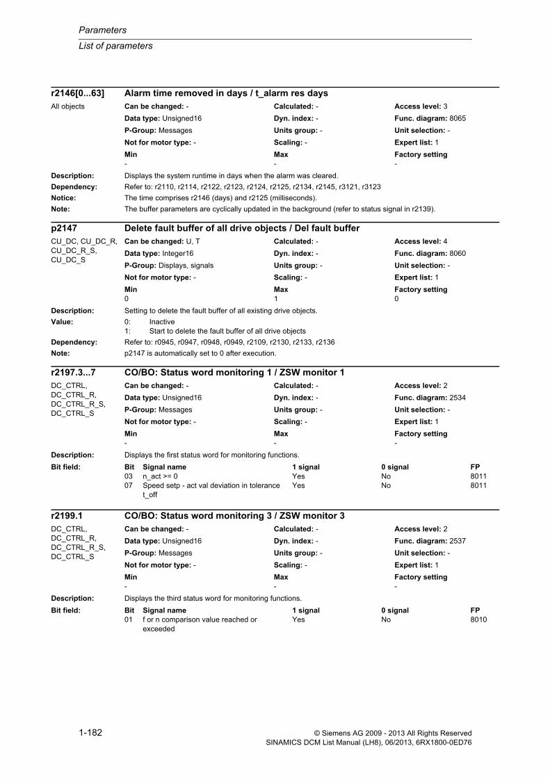
Parameters
List of parameters
1-182 © Siemens AG 2009 - 2013 All Rights ReservedSINAMICS DCM List Manual (LH8), 06/2013, 6RX1800-0ED76
Description: Displays the system runtime in days when the alarm was cleared.
Dependency: Refer to: r2110, r2114, r2122, r2123, r2124, r2125, r2134, r2145, r3121, r3123
Notice: The time comprises r2146 (days) and r2125 (milliseconds).
Note: The buffer parameters are cyclically updated in the background (refer to status signal in r2139).
Description: Setting to delete the fault buffer of all existing drive objects.
Value: 0: Inactive1: Start to delete the fault buffer of all drive objects
Dependency: Refer to: r0945, r0947, r0948, r0949, r2109, r2130, r2133, r2136
Note: p2147 is automatically set to 0 after execution.
Description: Displays the first status word for monitoring functions.
Description: Displays the third status word for monitoring functions.
r2146[0...63] Alarm time removed in days / t_alarm res daysAll objects Can be changed: - Calculated: - Access level: 3
Data type: Unsigned16 Dyn. index: - Func. diagram: 8065
P-Group: Messages Units group: - Unit selection: -
Not for motor type: - Scaling: - Expert list: 1
Min Max Factory setting - - -
p2147 Delete fault buffer of all drive objects / Del fault bufferCU_DC, CU_DC_R, CU_DC_R_S, CU_DC_S
Can be changed: U, T Calculated: - Access level: 4
Data type: Integer16 Dyn. index: - Func. diagram: 8060
P-Group: Displays, signals Units group: - Unit selection: -
Not for motor type: - Scaling: - Expert list: 1
Min Max Factory setting 0 1 0
r2197.3...7 CO/BO: Status word monitoring 1 / ZSW monitor 1DC_CTRL, DC_CTRL_R, DC_CTRL_R_S, DC_CTRL_S
Can be changed: - Calculated: - Access level: 2
Data type: Unsigned16 Dyn. index: - Func. diagram: 2534
P-Group: Messages Units group: - Unit selection: -
Not for motor type: - Scaling: - Expert list: 1
Min Max Factory setting - - -
Bit field: Bit Signal name 1 signal 0 signal FP03 n_act >= 0 Yes No 801107 Speed setp - act val deviation in tolerance
t_offYes No 8011
r2199.1 CO/BO: Status word monitoring 3 / ZSW monitor 3DC_CTRL, DC_CTRL_R, DC_CTRL_R_S, DC_CTRL_S
Can be changed: - Calculated: - Access level: 2
Data type: Unsigned16 Dyn. index: - Func. diagram: 2537
P-Group: Messages Units group: - Unit selection: -
Not for motor type: - Scaling: - Expert list: 1
Min Max Factory setting - - -
Bit field: Bit Signal name 1 signal 0 signal FP01 f or n comparison value reached or
exceededYes No 8010

List of parameters
Parameters
1-183© Siemens AG 2009 - 2013 All Rights ReservedSINAMICS DCM List Manual (LH8), 06/2013, 6RX1800-0ED76
Description: Sets the signal source to switch in/switch out the technology controller.
The technology controller is switched in with a 1 signal.
Description: Sets the configuration of the technology controller.
Dependency: Refer to: p2257, p2258, p2267, p2268, p2280, p2285
Note: Re bit 00 = 0:
The ramp-down time (p2258) switches to the ramp-up time (p2257) when the sign for the output signal r2260 changes. When the sign changes, the output signal is kept at zero for one arithmetic cycle.
Re bit 00 = 1:
When r2260 exhibits a positive gradient, the ramp-up time (p2257) is active; when it exhibits a negative gradient, the ramp-down time (p2258) is active. The sign for r2260 does not have any effect on the ramp time.
Re bit 01 = 0:
The integration time of the PID controller is evaluated with the gain factor Kp (p2280) (p2285 = integral time).
Re bit 01 = 1:
The integration time of the PID controller is independent of the gain factor (p2285 = integration time) if p2280 > 0.
Re bit 02 = 0:
When the PID controller is de-activated via p2200, the output signal r2294 is reduced to zero via the ramp-down time p2293.
Re bit 02 = 1:
When the PID controller is de-activated via p2200, the output signal r2294 is set directly to zero.
Re bit 03 = 0:
The actual values are not limited by p2267 and p2268.
Re bit 03 = 1:
The actual values are limited by p2267 and p2268.
p2200[0...n] BI: Technology controller enable / Tec_ctrl enableDC_CTRL (Tech_ctrl), DC_CTRL_R (Tech_ctrl), DC_CTRL_R_S (Tech_ctrl), DC_CTRL_S (Tech_ctrl)
Can be changed: T Calculated: - Access level: 2
Data type: Unsigned32 / Binary Dyn. index: CDS, p0170 Func. diagram: 7958
P-Group: Technology Units group: - Unit selection: -
Not for motor type: - Scaling: - Expert list: 1
Min Max Factory setting - - 0
p2252 Technology controller configuration / Tec_ctrl configDC_CTRL (Tech_ctrl), DC_CTRL_R (Tech_ctrl), DC_CTRL_R_S (Tech_ctrl), DC_CTRL_S (Tech_ctrl)
Can be changed: U, T Calculated: - Access level: 3
Data type: Unsigned16 Dyn. index: - Func. diagram: -
P-Group: Modulation Units group: - Unit selection: -
Not for motor type: - Scaling: - Expert list: 1
Min Max Factory setting - - 0111 bin
Bit field: Bit Signal name 1 signal 0 signal FP00 Ramp-up/down time independent of set-
point signYes No -
01 Integrator independent of Kp Yes No -02 Output signal without ramp active Yes No -03 Act val lim Yes No -

Parameters
List of parameters
1-184 © Siemens AG 2009 - 2013 All Rights ReservedSINAMICS DCM List Manual (LH8), 06/2013, 6RX1800-0ED76
Description: Sets the signal source for the setpoint 1 of the technology controller.
Dependency: Refer to: p2254, p2255
Description: Sets the signal source for the setpoint 2 of the technology controller.
Dependency: Refer to: p2253, p2256
Description: Sets the scaling for the setpoint 1 of the technology controller.
Dependency: Refer to: p2253
Description: Sets the scaling for the setpoint 2 of the technology controller.
Dependency: Refer to: p2254
p2253[0...n] CI: Technology controller setpoint 1 / Tec_ctrl setp 1DC_CTRL (Tech_ctrl), DC_CTRL_R (Tech_ctrl), DC_CTRL_R_S (Tech_ctrl), DC_CTRL_S (Tech_ctrl)
Can be changed: U, T Calculated: - Access level: 2
Data type: Unsigned32 / FloatingPoint32 Dyn. index: CDS, p0170 Func. diagram: 7958
P-Group: Technology Units group: - Unit selection: -
Not for motor type: - Scaling: PERCENT Expert list: 1
Min Max Factory setting - - 0
p2254[0...n] CI: Technology controller setpoint 2 / Tec_ctrl setp 2DC_CTRL (Tech_ctrl), DC_CTRL_R (Tech_ctrl), DC_CTRL_R_S (Tech_ctrl), DC_CTRL_S (Tech_ctrl)
Can be changed: U, T Calculated: - Access level: 3
Data type: Unsigned32 / FloatingPoint32 Dyn. index: CDS, p0170 Func. diagram: 7958
P-Group: Technology Units group: - Unit selection: -
Not for motor type: - Scaling: PERCENT Expert list: 1
Min Max Factory setting - - 0
p2255 Technology controller setpoint 1 scaling / Tec_ctrl set1 scalDC_CTRL (Tech_ctrl), DC_CTRL_R (Tech_ctrl), DC_CTRL_R_S (Tech_ctrl), DC_CTRL_S (Tech_ctrl)
Can be changed: U, T Calculated: - Access level: 3
Data type: FloatingPoint32 Dyn. index: - Func. diagram: 7958
P-Group: Technology Units group: - Unit selection: -
Not for motor type: - Scaling: - Expert list: 1
Min Max Factory setting 0.00 [%] 100.00 [%] 100.00 [%]
p2256 Technology controller setpoint 2 scaling / Tec_ctrl set2 scalDC_CTRL (Tech_ctrl), DC_CTRL_R (Tech_ctrl), DC_CTRL_R_S (Tech_ctrl), DC_CTRL_S (Tech_ctrl)
Can be changed: U, T Calculated: - Access level: 3
Data type: FloatingPoint32 Dyn. index: - Func. diagram: 7958
P-Group: Technology Units group: - Unit selection: -
Not for motor type: - Scaling: - Expert list: 1
Min Max Factory setting 0.00 [%] 100.00 [%] 100.00 [%]

List of parameters
Parameters
1-185© Siemens AG 2009 - 2013 All Rights ReservedSINAMICS DCM List Manual (LH8), 06/2013, 6RX1800-0ED76
Description: Sets the ramp-up time of the technology controller.
Dependency: Refer to: p2252, p2258
Note: The ramp-up time is referred to 100 %.
Description: Sets the ramp-down time of the technology controller.
Dependency: Refer to: p2252, p2257
Note: The ramp-down time is referred to 100 %.
Description: Sets the setpoint after the ramp-function generator of the technology controller.
Description: Sets the time constant for the setpoint filter (PT1) of the technology controller.
p2257 Technology controller ramp-up time / Tec_ctrl t_ramp-upDC_CTRL (Tech_ctrl), DC_CTRL_R (Tech_ctrl), DC_CTRL_R_S (Tech_ctrl), DC_CTRL_S (Tech_ctrl)
Can be changed: U, T Calculated: - Access level: 2
Data type: FloatingPoint32 Dyn. index: - Func. diagram: 7958
P-Group: Technology Units group: - Unit selection: -
Not for motor type: - Scaling: - Expert list: 1
Min Max Factory setting 0.00 [s] 650.00 [s] 1.00 [s]
p2258 Technology controller ramp-down time / Tec_ctrl t_ramp-dnDC_CTRL (Tech_ctrl), DC_CTRL_R (Tech_ctrl), DC_CTRL_R_S (Tech_ctrl), DC_CTRL_S (Tech_ctrl)
Can be changed: U, T Calculated: - Access level: 2
Data type: FloatingPoint32 Dyn. index: - Func. diagram: 7958
P-Group: Technology Units group: - Unit selection: -
Not for motor type: - Scaling: - Expert list: 1
Min Max Factory setting 0.00 [s] 650.00 [s] 1.00 [s]
r2260 CO: Technology controller setpoint after ramp-function generator / Tec_ctr set aftRFG
DC_CTRL (Tech_ctrl), DC_CTRL_R (Tech_ctrl), DC_CTRL_R_S (Tech_ctrl), DC_CTRL_S (Tech_ctrl)
Can be changed: - Calculated: - Access level: 2
Data type: FloatingPoint32 Dyn. index: - Func. diagram: 7958
P-Group: Technology Units group: 9_1 Unit selection: p0595
Not for motor type: - Scaling: PERCENT Expert list: 1
Min Max Factory setting - [%] - [%] - [%]
p2261 Technology controller setpoint filter time constant / Tec_ctrl set TDC_CTRL (Tech_ctrl), DC_CTRL_R (Tech_ctrl), DC_CTRL_R_S (Tech_ctrl), DC_CTRL_S (Tech_ctrl)
Can be changed: U, T Calculated: - Access level: 3
Data type: FloatingPoint32 Dyn. index: - Func. diagram: 7958
P-Group: Technology Units group: - Unit selection: -
Not for motor type: - Scaling: - Expert list: 1
Min Max Factory setting 0.000 [s] 60.000 [s] 0.000 [s]

Parameters
List of parameters
1-186 © Siemens AG 2009 - 2013 All Rights ReservedSINAMICS DCM List Manual (LH8), 06/2013, 6RX1800-0ED76
Description: Displays the smoothed setpoint after the setpoint filter (PT1) of the technology controller.
Description: Sets the technology controller type.
Value: 0: D component in the actual value signal1: D component in the fault signal
Description: Sets the signal source for the actual value of the technology controller.
Description: Sets the time constant for the actual value filter (PT1) of the technology controller.
r2262 CO: Technology controller setpoint after filter / Tec_ctr set aftFltDC_CTRL (Tech_ctrl), DC_CTRL_R (Tech_ctrl), DC_CTRL_R_S (Tech_ctrl), DC_CTRL_S (Tech_ctrl)
Can be changed: - Calculated: - Access level: 3
Data type: FloatingPoint32 Dyn. index: - Func. diagram: 7958
P-Group: Technology Units group: 9_1 Unit selection: p0595
Not for motor type: - Scaling: PERCENT Expert list: 1
Min Max Factory setting - [%] - [%] - [%]
p2263 Technology controller type / Tec_ctrl typeDC_CTRL (Tech_ctrl), DC_CTRL_R (Tech_ctrl), DC_CTRL_R_S (Tech_ctrl), DC_CTRL_S (Tech_ctrl)
Can be changed: T Calculated: - Access level: 3
Data type: Integer16 Dyn. index: - Func. diagram: 7958
P-Group: Technology Units group: - Unit selection: -
Not for motor type: - Scaling: - Expert list: 1
Min Max Factory setting 0 1 0
p2264[0...n] CI: Technology controller actual value / Tec_ctrl act valDC_CTRL (Tech_ctrl), DC_CTRL_R (Tech_ctrl), DC_CTRL_R_S (Tech_ctrl), DC_CTRL_S (Tech_ctrl)
Can be changed: U, T Calculated: - Access level: 2
Data type: Unsigned32 / FloatingPoint32 Dyn. index: CDS, p0170 Func. diagram: 7958
P-Group: Technology Units group: - Unit selection: -
Not for motor type: - Scaling: PERCENT Expert list: 1
Min Max Factory setting - - 0
p2265 Technology controller actual value filter time constant / Tec_ctrl act TDC_CTRL (Tech_ctrl), DC_CTRL_R (Tech_ctrl), DC_CTRL_R_S (Tech_ctrl), DC_CTRL_S (Tech_ctrl)
Can be changed: U, T Calculated: - Access level: 2
Data type: FloatingPoint32 Dyn. index: - Func. diagram: 7958
P-Group: Technology Units group: - Unit selection: -
Not for motor type: - Scaling: - Expert list: 1
Min Max Factory setting 0.000 [s] 60.000 [s] 0.000 [s]

List of parameters
Parameters
1-187© Siemens AG 2009 - 2013 All Rights ReservedSINAMICS DCM List Manual (LH8), 06/2013, 6RX1800-0ED76
Description: Displays the smoothed actual value after the filter (PT1) of the technology controller
Description: Sets the upper limit for the actual value signal of the technology controller.
Dependency: Refer to: p2252, p2264, p2265, p2271
Notice: If the actual value exceeds this upper limit, this results in fault F07426.
Note: Limiting only active for p2252.3 = 1.
Description: Sets the lower limit for the actual value signal of the technology controller.
Dependency: Refer to: p2264, p2265, p2271
Notice: If the actual value falls below this lower limit, this results in fault F07426.
Note: Limiting only active for p2252.3 = 1.
Description: Sets the scaling factor for the actual value of the technology controller.
r2266 CO: Technology controller actual value after filter / Tec_ctr act aftFltDC_CTRL (Tech_ctrl), DC_CTRL_R (Tech_ctrl), DC_CTRL_R_S (Tech_ctrl), DC_CTRL_S (Tech_ctrl)
Can be changed: - Calculated: - Access level: 2
Data type: FloatingPoint32 Dyn. index: - Func. diagram: 7958
P-Group: Technology Units group: 9_1 Unit selection: p0595
Not for motor type: - Scaling: PERCENT Expert list: 1
Min Max Factory setting - [%] - [%] - [%]
p2267 Technology controller upper limit actual value / Tec_ctrl u_lim actDC_CTRL (Tech_ctrl), DC_CTRL_R (Tech_ctrl), DC_CTRL_R_S (Tech_ctrl), DC_CTRL_S (Tech_ctrl)
Can be changed: U, T Calculated: - Access level: 3
Data type: FloatingPoint32 Dyn. index: - Func. diagram: 7958
P-Group: Technology Units group: 9_1 Unit selection: p0595
Not for motor type: - Scaling: PERCENT Expert list: 1
Min Max Factory setting -200.00 [%] 200.00 [%] 200.00 [%]
p2268 Technology controller lower limit actual value / Tec_ctrl l_lim actDC_CTRL (Tech_ctrl), DC_CTRL_R (Tech_ctrl), DC_CTRL_R_S (Tech_ctrl), DC_CTRL_S (Tech_ctrl)
Can be changed: U, T Calculated: - Access level: 3
Data type: FloatingPoint32 Dyn. index: - Func. diagram: 7958
P-Group: Technology Units group: 9_1 Unit selection: p0595
Not for motor type: - Scaling: PERCENT Expert list: 1
Min Max Factory setting -200.00 [%] 200.00 [%] -200.00 [%]
p2269 Technology controller gain actual value / Tech_ctrl gain actDC_CTRL (Tech_ctrl), DC_CTRL_R (Tech_ctrl), DC_CTRL_R_S (Tech_ctrl), DC_CTRL_S (Tech_ctrl)
Can be changed: U, T Calculated: - Access level: 3
Data type: FloatingPoint32 Dyn. index: - Func. diagram: 7958
P-Group: Technology Units group: - Unit selection: -
Not for motor type: - Scaling: - Expert list: 1
Min Max Factory setting 0.00 [%] 500.00 [%] 100.00 [%]

Parameters
List of parameters
1-188 © Siemens AG 2009 - 2013 All Rights ReservedSINAMICS DCM List Manual (LH8), 06/2013, 6RX1800-0ED76
Dependency: Refer to: p2264, p2265, p2267, p2268, p2271
Note: For 100%, the actual value is not changed.
Description: Setting to use an arithmetic function for the actual value signal of the technology controller.
Value: 0: No function1: Root function (root from x)2: Square function (x * x)3: Cube function (x * x * x)
Dependency: Refer to: p2264, p2265, p2267, p2268, p2269, p2271
Description: Setting to invert the actual value signal of the technology controller.
The inversion depends on the sensor type for the actual value signal.
Value: 0: No inversion1: Inversion actual value signal
Caution: If the actual value inversion is incorrectly selected, then the closed-loop control with the technology controller can become unstable and can oscillate!
Note: The correct setting can be determined as follows:
- inhibit the technology controller (p2200 = 0).
- increase the motor speed and in so doing, measure the actual value signal of the technology controller.
--> If the actual value increases as the motor speed increases, then p2271 should be set to 0 (no inversion).
--> If the actual value decreases as the motor speed increases, then p2271 should be set to 1 (the actual value sig-nal is inverted).
p2270 Technology controller actual value function / Tec_ctr ActVal fctDC_CTRL (Tech_ctrl), DC_CTRL_R (Tech_ctrl), DC_CTRL_R_S (Tech_ctrl), DC_CTRL_S (Tech_ctrl)
Can be changed: U, T Calculated: - Access level: 3
Data type: Integer16 Dyn. index: - Func. diagram: 7958
P-Group: Technology Units group: - Unit selection: -
Not for motor type: - Scaling: - Expert list: 1
Min Max Factory setting 0 3 0
p2271 Technology controller actual value inversion (sensor type) / Tech_ctrl act invDC_CTRL (Tech_ctrl), DC_CTRL_R (Tech_ctrl), DC_CTRL_R_S (Tech_ctrl), DC_CTRL_S (Tech_ctrl)
Can be changed: T Calculated: - Access level: 3
Data type: Integer16 Dyn. index: - Func. diagram: -
P-Group: Technology Units group: - Unit selection: -
Not for motor type: - Scaling: - Expert list: 1
Min Max Factory setting 0 1 0

List of parameters
Parameters
1-189© Siemens AG 2009 - 2013 All Rights ReservedSINAMICS DCM List Manual (LH8), 06/2013, 6RX1800-0ED76
Description: Displays the scaled actual value signal of the technology controller.
Dependency: Refer to: p2264, p2265, r2266, p2267, p2268, p2269, p2270, p2271
Description: Displays the error (system deviation) between the setpoint and actual value of the technology controller.
Dependency: Refer to: p2263
Description: Sets the time constant for the differentiation (D component) of the technology controller.
Note: p2274 = 0: Differentiation is disabled.
Description: Sets the proportional gain (P component) of the technology controller.
Dependency: Refer to: p2252
Note: p2280 = 0: The proportional gain is disabled.
r2272 CO: Technology controller actual value scaled / Tech_ctrl act scalDC_CTRL (Tech_ctrl), DC_CTRL_R (Tech_ctrl), DC_CTRL_R_S (Tech_ctrl), DC_CTRL_S (Tech_ctrl)
Can be changed: - Calculated: - Access level: 2
Data type: FloatingPoint32 Dyn. index: - Func. diagram: 7958
P-Group: Technology Units group: 9_1 Unit selection: p0595
Not for motor type: - Scaling: PERCENT Expert list: 1
Min Max Factory setting - [%] - [%] - [%]
r2273 CO: Technology controller error / Tec_ctrl errorDC_CTRL (Tech_ctrl), DC_CTRL_R (Tech_ctrl), DC_CTRL_R_S (Tech_ctrl), DC_CTRL_S (Tech_ctrl)
Can be changed: - Calculated: - Access level: 2
Data type: FloatingPoint32 Dyn. index: - Func. diagram: 7958
P-Group: Technology Units group: 9_1 Unit selection: p0595
Not for motor type: - Scaling: PERCENT Expert list: 1
Min Max Factory setting - [%] - [%] - [%]
p2274 Technology controller differentiation time constant / Tec_ctrl D comp TDC_CTRL (Tech_ctrl), DC_CTRL_R (Tech_ctrl), DC_CTRL_R_S (Tech_ctrl), DC_CTRL_S (Tech_ctrl)
Can be changed: U, T Calculated: - Access level: 2
Data type: FloatingPoint32 Dyn. index: - Func. diagram: 7958
P-Group: Technology Units group: - Unit selection: -
Not for motor type: - Scaling: - Expert list: 1
Min Max Factory setting 0.000 [s] 60.000 [s] 0.000 [s]
p2280 Technology controller proportional gain / Tec_ctrl KpDC_CTRL (Tech_ctrl), DC_CTRL_R (Tech_ctrl), DC_CTRL_R_S (Tech_ctrl), DC_CTRL_S (Tech_ctrl)
Can be changed: U, T Calculated: - Access level: 2
Data type: FloatingPoint32 Dyn. index: - Func. diagram: 7958
P-Group: Technology Units group: - Unit selection: -
Not for motor type: - Scaling: - Expert list: 1
Min Max Factory setting 0.000 1000.000 1.000

Parameters
List of parameters
1-190 © Siemens AG 2009 - 2013 All Rights ReservedSINAMICS DCM List Manual (LH8), 06/2013, 6RX1800-0ED76
Description: Sets the integral time (I component, integrating time constant) of the technology controller.
Dependency: Refer to: p2252
Note: p2285 = 0: The integral time is disabled.
Description: Sets the signal source to hold the integrator for the technology controller.
Description: Sets the signal source for the pre-control signal of the technology controller.
Description: Sets the maximum limit of the technology controller.
Dependency: Refer to: p2292
Caution: The maximum limit must always be greater than the minimum limit (p2291 > p2292).
p2285 Technology controller integral time / Tec_ctrl TnDC_CTRL (Tech_ctrl), DC_CTRL_R (Tech_ctrl), DC_CTRL_R_S (Tech_ctrl), DC_CTRL_S (Tech_ctrl)
Can be changed: U, T Calculated: - Access level: 2
Data type: FloatingPoint32 Dyn. index: - Func. diagram: 7958
P-Group: Technology Units group: - Unit selection: -
Not for motor type: - Scaling: - Expert list: 1
Min Max Factory setting 0.000 [s] 60.000 [s] 0.000 [s]
p2286[0...n] BI: Hold technology controller integrator / Tec_ctr integ stopDC_CTRL (Tech_ctrl), DC_CTRL_R (Tech_ctrl), DC_CTRL_R_S (Tech_ctrl), DC_CTRL_S (Tech_ctrl)
Can be changed: T Calculated: - Access level: 3
Data type: Unsigned32 / Binary Dyn. index: CDS, p0170 Func. diagram: 7958
P-Group: Technology Units group: - Unit selection: -
Not for motor type: - Scaling: - Expert list: 1
Min Max Factory setting - - 0
p2289[0...n] CI: Technology controller pre-control signal / Tec_ctrl prectrlDC_CTRL (Tech_ctrl), DC_CTRL_R (Tech_ctrl), DC_CTRL_R_S (Tech_ctrl), DC_CTRL_S (Tech_ctrl)
Can be changed: U, T Calculated: - Access level: 2
Data type: Unsigned32 / FloatingPoint32 Dyn. index: CDS, p0170 Func. diagram: 7958
P-Group: Technology Units group: - Unit selection: -
Not for motor type: - Scaling: PERCENT Expert list: 1
Min Max Factory setting - - 0
p2291 CO: Technology controller maximum limiting / Tec_ctrl max_limDC_CTRL (Tech_ctrl), DC_CTRL_R (Tech_ctrl), DC_CTRL_R_S (Tech_ctrl), DC_CTRL_S (Tech_ctrl)
Can be changed: U, T Calculated: - Access level: 2
Data type: FloatingPoint32 Dyn. index: - Func. diagram: 7958
P-Group: Technology Units group: - Unit selection: -
Not for motor type: - Scaling: PERCENT Expert list: 1
Min Max Factory setting -200.00 [%] 200.00 [%] 100.00 [%]

List of parameters
Parameters
1-191© Siemens AG 2009 - 2013 All Rights ReservedSINAMICS DCM List Manual (LH8), 06/2013, 6RX1800-0ED76
Description: Sets the minimum limit of the technology controller.
Dependency: Refer to: p2291
Caution: The maximum limit must always be greater than the minimum limit (p2291 > p2292).
Description: Sets the ramping time for the output signal of the technology controller.
Dependency: Refer to: p2291, p2292
Note: The time refers to the set maximum and minimum limits (p2291, p2292).
Description: Displays the output signal of the technology controller.
Dependency: Refer to: p2295
p2292 CO: Technology controller minimum limiting / Tec_ctrl min_limDC_CTRL (Tech_ctrl), DC_CTRL_R (Tech_ctrl), DC_CTRL_R_S (Tech_ctrl), DC_CTRL_S (Tech_ctrl)
Can be changed: U, T Calculated: - Access level: 2
Data type: FloatingPoint32 Dyn. index: - Func. diagram: 7958
P-Group: Technology Units group: - Unit selection: -
Not for motor type: - Scaling: PERCENT Expert list: 1
Min Max Factory setting -200.00 [%] 200.00 [%] 0.00 [%]
p2293 Technology controller ramp-up/ramp-down time / Tec_ctr ramp up/dnDC_CTRL (Tech_ctrl), DC_CTRL_R (Tech_ctrl), DC_CTRL_R_S (Tech_ctrl), DC_CTRL_S (Tech_ctrl)
Can be changed: U, T Calculated: - Access level: 3
Data type: FloatingPoint32 Dyn. index: - Func. diagram: 7958
P-Group: Technology Units group: - Unit selection: -
Not for motor type: - Scaling: - Expert list: 1
Min Max Factory setting 0.00 [s] 100.00 [s] 1.00 [s]
r2294 CO: Technology controller output signal / Tec_ctrl outp_sigDC_CTRL (Tech_ctrl), DC_CTRL_R (Tech_ctrl), DC_CTRL_R_S (Tech_ctrl), DC_CTRL_S (Tech_ctrl)
Can be changed: - Calculated: - Access level: 2
Data type: FloatingPoint32 Dyn. index: - Func. diagram: 7958
P-Group: Technology Units group: - Unit selection: -
Not for motor type: - Scaling: PERCENT Expert list: 1
Min Max Factory setting - [%] - [%] - [%]
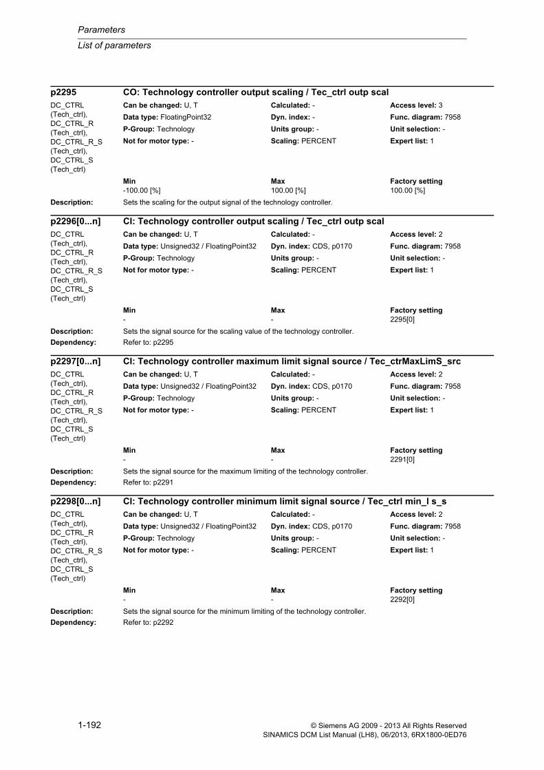
Parameters
List of parameters
1-192 © Siemens AG 2009 - 2013 All Rights ReservedSINAMICS DCM List Manual (LH8), 06/2013, 6RX1800-0ED76
Description: Sets the scaling for the output signal of the technology controller.
Description: Sets the signal source for the scaling value of the technology controller.
Dependency: Refer to: p2295
Description: Sets the signal source for the maximum limiting of the technology controller.
Dependency: Refer to: p2291
Description: Sets the signal source for the minimum limiting of the technology controller.
Dependency: Refer to: p2292
p2295 CO: Technology controller output scaling / Tec_ctrl outp scalDC_CTRL (Tech_ctrl), DC_CTRL_R (Tech_ctrl), DC_CTRL_R_S (Tech_ctrl), DC_CTRL_S (Tech_ctrl)
Can be changed: U, T Calculated: - Access level: 3
Data type: FloatingPoint32 Dyn. index: - Func. diagram: 7958
P-Group: Technology Units group: - Unit selection: -
Not for motor type: - Scaling: PERCENT Expert list: 1
Min Max Factory setting -100.00 [%] 100.00 [%] 100.00 [%]
p2296[0...n] CI: Technology controller output scaling / Tec_ctrl outp scalDC_CTRL (Tech_ctrl), DC_CTRL_R (Tech_ctrl), DC_CTRL_R_S (Tech_ctrl), DC_CTRL_S (Tech_ctrl)
Can be changed: U, T Calculated: - Access level: 2
Data type: Unsigned32 / FloatingPoint32 Dyn. index: CDS, p0170 Func. diagram: 7958
P-Group: Technology Units group: - Unit selection: -
Not for motor type: - Scaling: PERCENT Expert list: 1
Min Max Factory setting - - 2295[0]
p2297[0...n] CI: Technology controller maximum limit signal source / Tec_ctrMaxLimS_srcDC_CTRL (Tech_ctrl), DC_CTRL_R (Tech_ctrl), DC_CTRL_R_S (Tech_ctrl), DC_CTRL_S (Tech_ctrl)
Can be changed: U, T Calculated: - Access level: 2
Data type: Unsigned32 / FloatingPoint32 Dyn. index: CDS, p0170 Func. diagram: 7958
P-Group: Technology Units group: - Unit selection: -
Not for motor type: - Scaling: PERCENT Expert list: 1
Min Max Factory setting - - 2291[0]
p2298[0...n] CI: Technology controller minimum limit signal source / Tec_ctrl min_l s_sDC_CTRL (Tech_ctrl), DC_CTRL_R (Tech_ctrl), DC_CTRL_R_S (Tech_ctrl), DC_CTRL_S (Tech_ctrl)
Can be changed: U, T Calculated: - Access level: 2
Data type: Unsigned32 / FloatingPoint32 Dyn. index: CDS, p0170 Func. diagram: 7958
P-Group: Technology Units group: - Unit selection: -
Not for motor type: - Scaling: PERCENT Expert list: 1
Min Max Factory setting - - 2292[0]

List of parameters
Parameters
1-193© Siemens AG 2009 - 2013 All Rights ReservedSINAMICS DCM List Manual (LH8), 06/2013, 6RX1800-0ED76
Description: Sets the signal source for the offset of the output limiting of the technology controller.
Description: Setting to invert the fault signal of the technology controller.
The setting depends on the type of control loop.
Value: 0: No inversion1: Inversion
Caution: If the actual value inversion is incorrectly selected, then the closed-loop control with the technology controller can become unstable and can oscillate!
Note: The correct setting can be determined as follows:
- inhibit the technology controller (p2200 = 0).
- increase the motor speed and in so doing, measure the actual value signal (of the technology controller).
- if the actual value increases with increasing motor speed, then the inversion should be switched out.
- if the actual value decreases with increasing motor speed, then the inversion should be set.
If value = 0:
The drive reduces the output speed when the actual value rises (e.g. for heating fans, intake pump, compressor).
If value = 1:
The drive increases the output speed when the actual value increases (e.g. for cooling fans, discharge pumps).
Description: Displays the status word of the technology controller.
p2299[0...n] CI: Technology controller limit offset / Tech_ctrl lim offsDC_CTRL (Tech_ctrl), DC_CTRL_R (Tech_ctrl), DC_CTRL_R_S (Tech_ctrl), DC_CTRL_S (Tech_ctrl)
Can be changed: U, T Calculated: - Access level: 2
Data type: Unsigned32 / FloatingPoint32 Dyn. index: CDS, p0170 Func. diagram: 7958
P-Group: Technology Units group: - Unit selection: -
Not for motor type: - Scaling: PERCENT Expert list: 1
Min Max Factory setting - - 0
p2306 Technology controller fault signal inversion / Tec_ctrl fault invDC_CTRL (Tech_ctrl), DC_CTRL_R (Tech_ctrl), DC_CTRL_R_S (Tech_ctrl), DC_CTRL_S (Tech_ctrl)
Can be changed: T Calculated: - Access level: 3
Data type: Integer16 Dyn. index: - Func. diagram: -
P-Group: Technology Units group: - Unit selection: -
Not for motor type: - Scaling: - Expert list: 1
Min Max Factory setting 0 1 0
r2349.0...11 CO/BO: Technology controller status word / Tec_ctrl statusDC_CTRL (Tech_ctrl), DC_CTRL_R (Tech_ctrl), DC_CTRL_R_S (Tech_ctrl), DC_CTRL_S (Tech_ctrl)
Can be changed: - Calculated: - Access level: 3
Data type: Unsigned32 Dyn. index: - Func. diagram: 7958
P-Group: Technology Units group: - Unit selection: -
Not for motor type: - Scaling: - Expert list: 1
Min Max Factory setting - - -
Bit field: Bit Signal name 1 signal 0 signal FP00 Technology controller de-activated Yes No -01 Technology controller limited Yes No -

Parameters
List of parameters
1-194 © Siemens AG 2009 - 2013 All Rights ReservedSINAMICS DCM List Manual (LH8), 06/2013, 6RX1800-0ED76
Description: Sets the operating mode for the energy-saving mode function.
Value: 0: Energy-saving mode inhibited1: Energy-saving mode activated
Dependency: Refer to: p2200
Caution: When this function is active, the motor can start again automatically.
Note: When the energy-saving mode function (p2398 = 1) is activated, its behavior is defined as to whether the technol-ogy controller is additionally switched in (closed-loop) or switched out (open-loop).
The technology controller is enabled via binector input p2200 and its mode is set in p2251.
p2200 = 0, p2251 = 0, 1:
Energy-saving mode operates without technology controller (open-loop)
p2200 = 1, p2251 = 0:
Energy-saving mode operates with technology controller (closed-loop)
p2200 = 1, p2251 = 1:
Energy-saving mode operates without technology controller (open-loop) as its output is only used as supplementary setpoint and not as main setpoint.
Description: Sets the motor revolutions for the gearbox factor between the motor shaft and load shaft.
Gearbox factor = motor revolutions (p2504) / load revolutions (p2505)
Dependency: Refer to: p0432, p0433, p2505
Note: The gearbox factor between the encoder shaft and the motor shaft is set using p0432 and p0433.
02 Technology controller motorized potentiom-eter limited max.
Yes No -
03 Technology controller motorized potentiom-eter limited min.
Yes No -
08 Technology controller actual value at the minimum
Yes No -
09 Technology controller actual value at the maximum
Yes No -
10 Technology controller output at the mini-mum
Yes No -
11 Technology controller output at the maxi-mum
Yes No -
p2398 Energy-saving mode / En_save modeDC_CTRL (Tech_ctrl), DC_CTRL_R (Tech_ctrl), DC_CTRL_R_S (Tech_ctrl), DC_CTRL_S (Tech_ctrl)
Can be changed: T Calculated: - Access level: 3
Data type: Integer16 Dyn. index: - Func. diagram: -
P-Group: Technology Units group: - Unit selection: -
Not for motor type: - Scaling: - Expert list: 1
Min Max Factory setting 0 1 0
p2504[0...n] LR motor/load motor revolutions / Mot/load motor revDC_CTRL, DC_CTRL_R, DC_CTRL_R_S, DC_CTRL_S
Can be changed: C2(4) Calculated: - Access level: 1
Data type: Unsigned32 Dyn. index: DDS, p0180 Func. diagram: 4704, 4711
P-Group: Encoder Units group: - Unit selection: -
Not for motor type: - Scaling: - Expert list: 1
Min Max Factory setting 1 1048576 1
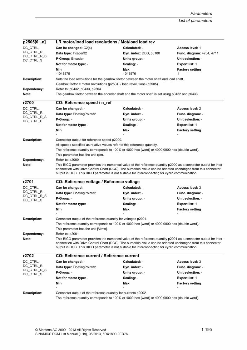
List of parameters
Parameters
1-195© Siemens AG 2009 - 2013 All Rights ReservedSINAMICS DCM List Manual (LH8), 06/2013, 6RX1800-0ED76
Description: Sets the load revolutions for the gearbox factor between the motor shaft and load shaft.
Gearbox factor = motor revolutions (p2504) / load revolutions (p2505)
Dependency: Refer to: p0432, p0433, p2504
Note: The gearbox factor between the encoder shaft and the motor shaft is set using p0432 and p0433.
Description: Connector output for reference speed p2000.
All speeds specified as relative values refer to this reference quantity.
The reference quantity corresponds to 100% or 4000 hex (word) or 4000 0000 hex (double word).
This parameter has the unit rpm.
Dependency: Refer to: p2000
Note: This BICO parameter provides the numerical value of the reference quantity p2000 as a connector output for inter-connection with Drive Control Chart (DCC). The numerical value can be adopted unchanged from this connector output in DCC. This BICO parameter is not suitable for interconnecting for cyclic communication.
Description: Connector output of the reference quantity for voltages p2001.
The reference quantity corresponds to 100% or 4000 hex (word) or 4000 0000 hex (double word).
This parameter has the unit [Vrms].
Dependency: Refer to: p2001
Note: This BICO parameter provides the numerical value of the reference quantity p2001 as a connector output for inter-connection with Drive Control Chart (DCC). The numerical value can be adopted unchanged from this connector output in DCC. This BICO parameter is not suitable for interconnecting for cyclic communication.
Description: Connector output of the reference quantity for currents p2002.
The reference quantity corresponds to 100% or 4000 hex (word) or 4000 0000 hex (double word).
p2505[0...n] LR motor/load load revolutions / Mot/load load revDC_CTRL, DC_CTRL_R, DC_CTRL_R_S, DC_CTRL_S
Can be changed: C2(4) Calculated: - Access level: 1
Data type: Integer32 Dyn. index: DDS, p0180 Func. diagram: 4704, 4711
P-Group: Encoder Units group: - Unit selection: -
Not for motor type: - Scaling: - Expert list: 1
Min Max Factory setting -1048576 1048576 1
r2700 CO: Reference speed / n_refDC_CTRL, DC_CTRL_R, DC_CTRL_R_S, DC_CTRL_S
Can be changed: - Calculated: - Access level: 2
Data type: FloatingPoint32 Dyn. index: - Func. diagram: -
P-Group: - Units group: - Unit selection: -
Not for motor type: - Scaling: - Expert list: 1
Min Max Factory setting - - -
r2701 CO: Reference voltage / Reference voltageDC_CTRL, DC_CTRL_R, DC_CTRL_R_S, DC_CTRL_S
Can be changed: - Calculated: - Access level: 3
Data type: FloatingPoint32 Dyn. index: - Func. diagram: -
P-Group: - Units group: - Unit selection: -
Not for motor type: - Scaling: - Expert list: 1
Min Max Factory setting - - -
r2702 CO: Reference current / Reference currentDC_CTRL, DC_CTRL_R, DC_CTRL_R_S, DC_CTRL_S
Can be changed: - Calculated: - Access level: 3
Data type: FloatingPoint32 Dyn. index: - Func. diagram: -
P-Group: - Units group: - Unit selection: -
Not for motor type: - Scaling: - Expert list: 1
Min Max Factory setting - - -

Parameters
List of parameters
1-196 © Siemens AG 2009 - 2013 All Rights ReservedSINAMICS DCM List Manual (LH8), 06/2013, 6RX1800-0ED76
This parameter has the unit Arms.
Dependency: Refer to: p2002
Note: This BICO parameter provides the numerical value of the reference quantity p2002 as a connector output for inter-connection with Drive Control Chart (DCC). The numerical value can be adopted unchanged from this connector output in DCC. This BICO parameter is not suitable for interconnecting for cyclic communication.
Description: Connector output of the reference quantity p2003 for torque (r0108.12 = 0) or force (r0108.12 = 1).
The reference quantity corresponds to 100% or 4000 hex (word) or 4000 0000 hex (double word).
The unit of this parameter is the same as the unit selected for p2003.
Dependency: p0505, r0108.12
Refer to: p2003
Note: This BICO parameter provides the numerical value of the reference quantity p2003 in the currently selected unit as a connector output for interconnection with Drive Control Chart (DCC). The numerical value can be adopted unchanged from this connector output in DCC. This BICO parameter is not suitable for interconnecting for cyclic communication.
Description: Connector output of the reference quantity for powers p2004.
The reference quantity corresponds to 100% or 4000 hex (word) or 4000 0000 hex (double word).
The unit of this parameter is the same as the unit selected for p2004.
Dependency: This value is calculated as voltage x current for the infeed and as torque x speed for closed-loop controls.
Refer to: r2004
Note: This BICO parameter provides the numerical value of the reference quantity p2004 in the currently selected unit as a connector output for interconnection with Drive Control Chart (DCC). The numerical value can be adopted unchanged from this connector output in DCC. This BICO parameter is not suitable for interconnecting for cyclic communication.
The reference power is calculated as follows:
- 2 * Pi * reference speed / 60 * reference torque (motor)
- reference voltage * reference current * root(3) (infeed)
Description: Connector output of the reference quantity for angles p2005.
The reference quantity corresponds to 100% or 4000 hex (word) or 4000 0000 hex (double word).
This parameter has the unit degree.
Dependency: Refer to: p2005
r2703 CO: Reference torque / Reference torqueDC_CTRL, DC_CTRL_R, DC_CTRL_R_S, DC_CTRL_S
Can be changed: - Calculated: - Access level: 3
Data type: FloatingPoint32 Dyn. index: - Func. diagram: -
P-Group: - Units group: - Unit selection: -
Not for motor type: - Scaling: - Expert list: 1
Min Max Factory setting - - -
r2704 CO: Reference power / Reference powerDC_CTRL, DC_CTRL_R, DC_CTRL_R_S, DC_CTRL_S
Can be changed: - Calculated: - Access level: 3
Data type: FloatingPoint32 Dyn. index: - Func. diagram: -
P-Group: - Units group: - Unit selection: -
Not for motor type: - Scaling: - Expert list: 1
Min Max Factory setting - - -
r2705 CO: Reference angle / Reference angleDC_CTRL, DC_CTRL_R, DC_CTRL_R_S, DC_CTRL_S
Can be changed: - Calculated: - Access level: 3
Data type: FloatingPoint32 Dyn. index: - Func. diagram: -
P-Group: - Units group: - Unit selection: -
Not for motor type: - Scaling: - Expert list: 1
Min Max Factory setting - - -

List of parameters
Parameters
1-197© Siemens AG 2009 - 2013 All Rights ReservedSINAMICS DCM List Manual (LH8), 06/2013, 6RX1800-0ED76
Note: This BICO parameter provides the numerical value of the reference quantity p2005 as a connector output for inter-connection with Drive Control Chart (DCC). The numerical value can be adopted unchanged from this connector output in DCC. This BICO parameter is not suitable for interconnecting for cyclic communication.
Description: Connector output of the reference quantity for temperatures.
The reference quantity corresponds to 100% or 4000 hex (word) or 4000 0000 hex (double word).
This parameter has the unit degree Celsius.
Note: This BICO parameter provides the numerical value of the reference quantity for the temperature as a connector out-put for interconnection with Drive Control Chart (DCC). The numerical value can be adopted unchanged from this connector output in DCC. This BICO parameter is not suitable for interconnecting for cyclic communication.
Description: Connector output of the reference quantity for temperatures.
All temperatures specified as relative value are referred to this reference quantity.
The reference quantity corresponds to 100% or 4000 hex (word) or 4000 0000 hex (double word).
This parameter has the unit degree Celsius.
Note: This BICO parameter provides the numerical value of the reference quantity for the temperature as a connector out-put for interconnection with Drive Control Chart (DCC). The numerical value can be adopted unchanged from this connector output in DCC. This BICO parameter is not suitable for interconnecting for cyclic communication.
Description: Connector output of the reference quantity for accelerations p2007.
The reference quantity corresponds to 100% or 4000 hex (word) or 4000 0000 hex (double word).
The unit of this parameter is the same as the unit selected for p2007.
Dependency: r0108.12, p0505
Refer to: p2007
Note: This BICO parameter provides the numerical value of the reference quantity p2007 as a connector output for inter-connection with Drive Control Chart (DCC). The numerical value in the currently selected unit can be adopted unchanged from this connector output in DCC. This BICO parameter is not suitable for interconnecting for cyclic communication.
r2706 CO: Reference temp / Reference tempDC_CTRL, DC_CTRL_R, DC_CTRL_R_S, DC_CTRL_S
Can be changed: - Calculated: - Access level: 3
Data type: FloatingPoint32 Dyn. index: - Func. diagram: -
P-Group: - Units group: - Unit selection: -
Not for motor type: - Scaling: - Expert list: 1
Min Max Factory setting - - -
r2706 CO: Reference temp / Reference tempTM150, TM31 Can be changed: - Calculated: - Access level: 3
Data type: FloatingPoint32 Dyn. index: - Func. diagram: -
P-Group: - Units group: - Unit selection: -
Not for motor type: - Scaling: - Expert list: 1
Min Max Factory setting - - -
r2707 CO: Reference acceleration / Ref accelDC_CTRL, DC_CTRL_R, DC_CTRL_R_S, DC_CTRL_S
Can be changed: - Calculated: - Access level: 3
Data type: FloatingPoint32 Dyn. index: - Func. diagram: -
P-Group: - Units group: - Unit selection: -
Not for motor type: - Scaling: - Expert list: 1
Min Max Factory setting - - -

Parameters
List of parameters
1-198 © Siemens AG 2009 - 2013 All Rights ReservedSINAMICS DCM List Manual (LH8), 06/2013, 6RX1800-0ED76
Description: Sets the configuration for position tracking of a load gear.
Note: For the following events, the non-volatile, saved position values are automatically reset:
- when an encoder replacement has been identified.
- when changing the configuration of the Encoder Data Set (EDS).
- when adjusting the absolute encoder again
Description: Sets the number of rotations that can be resolved for a rotary absolute encoder with activated position tracking of the load gear.
Dependency: This parameter is only of significance for an absolute encoder (p0404.1 = 1) with activated position tracking of the load gear (p2720.0 = 1).
Note: The resolution that is set must be able to be represented using r2723.
For rotary axes/modulo axes, the following applies:
This parameter is pre-set with p0421 and can be changed.
For linear axes, the following applies:
This parameter is pre-assigned with p0421, expanded by 6 bits for multiturn information (maximum number of over-flows) and cannot be changed.
Description: Sets a tolerance window for position tracking.
After the system is powered up, the difference between the saved position and the actual position is determined, and depending on this, the following is initiated:
Difference within the tolerance window --> The position is reproduced as a result of the encoder actual value.
Difference outside the tolerance window --> An appropriate message is output.
Caution: Rotation, e.g. through a complete encoder range is not detected.
p2720[0...n] Load gear configuration / Load gear configDC_CTRL, DC_CTRL_R, DC_CTRL_R_S, DC_CTRL_S
Can be changed: C2(1, 4) Calculated: - Access level: 1
Data type: Unsigned32 Dyn. index: DDS, p0180 Func. diagram: 4704
P-Group: Encoder Units group: - Unit selection: -
Not for motor type: - Scaling: - Expert list: 1
Min Max Factory setting - - 0000 bin
Bit field: Bit Signal name 1 signal 0 signal FP00 Load gear activate position tracking Yes No -01 Axis type Linear axis Rotary axis -02 Load gear reset position Yes No -
p2721[0...n] Load gear rotary absolute encoder revolutions virtual / Abs rot revDC_CTRL, DC_CTRL_R, DC_CTRL_R_S, DC_CTRL_S
Can be changed: C2(1, 4) Calculated: - Access level: 1
Data type: Unsigned32 Dyn. index: DDS, p0180 Func. diagram: 4704
P-Group: Encoder Units group: - Unit selection: -
Not for motor type: - Scaling: - Expert list: 1
Min Max Factory setting 0 4194303 0
p2722[0...n] Load gear position tracking tolerance window / Pos track tolDC_CTRL, DC_CTRL_R, DC_CTRL_R_S, DC_CTRL_S
Can be changed: C2(1, 4) Calculated: - Access level: 3
Data type: FloatingPoint32 Dyn. index: DDS, p0180 Func. diagram: -
P-Group: Encoder Units group: - Unit selection: -
Not for motor type: - Scaling: - Expert list: 1
Min Max Factory setting 0.00 4294967300.00 0.00
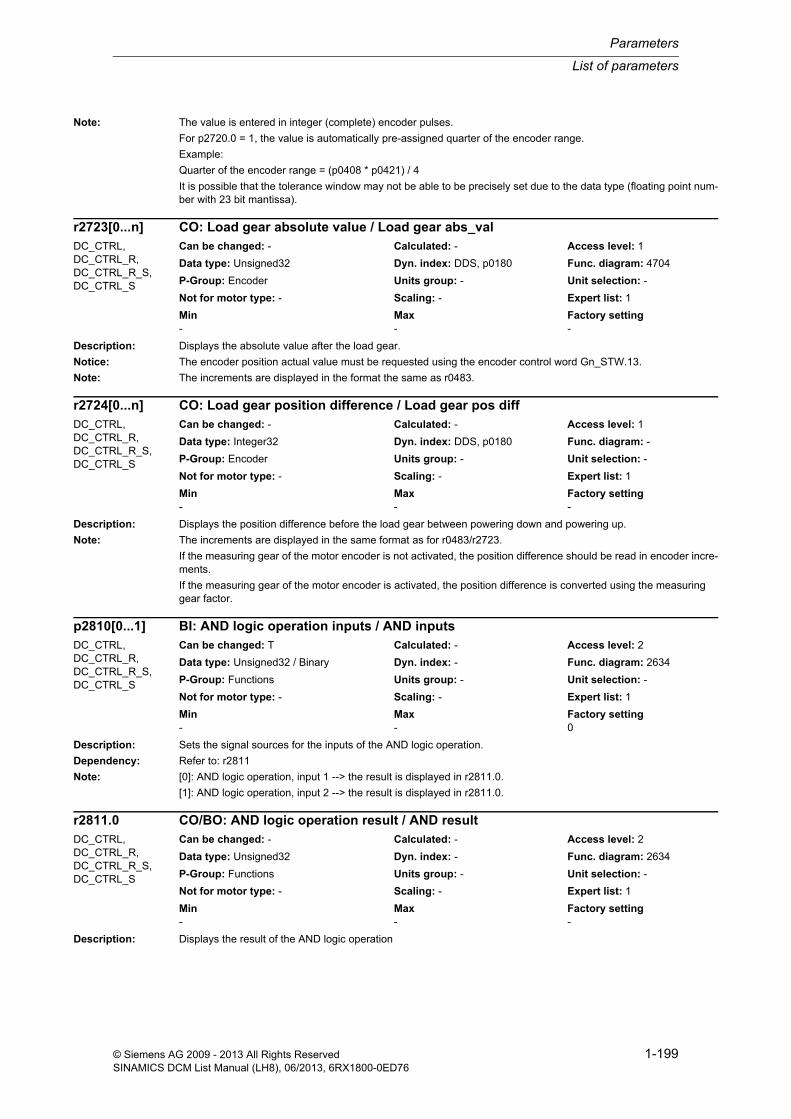
List of parameters
Parameters
1-199© Siemens AG 2009 - 2013 All Rights ReservedSINAMICS DCM List Manual (LH8), 06/2013, 6RX1800-0ED76
Note: The value is entered in integer (complete) encoder pulses.
For p2720.0 = 1, the value is automatically pre-assigned quarter of the encoder range.
Example:
Quarter of the encoder range = (p0408 * p0421) / 4
It is possible that the tolerance window may not be able to be precisely set due to the data type (floating point num-ber with 23 bit mantissa).
Description: Displays the absolute value after the load gear.
Notice: The encoder position actual value must be requested using the encoder control word Gn_STW.13.
Note: The increments are displayed in the format the same as r0483.
Description: Displays the position difference before the load gear between powering down and powering up.
Note: The increments are displayed in the same format as for r0483/r2723.
If the measuring gear of the motor encoder is not activated, the position difference should be read in encoder incre-ments.
If the measuring gear of the motor encoder is activated, the position difference is converted using the measuring gear factor.
Description: Sets the signal sources for the inputs of the AND logic operation.
Dependency: Refer to: r2811
Note: [0]: AND logic operation, input 1 --> the result is displayed in r2811.0.
[1]: AND logic operation, input 2 --> the result is displayed in r2811.0.
Description: Displays the result of the AND logic operation
r2723[0...n] CO: Load gear absolute value / Load gear abs_valDC_CTRL, DC_CTRL_R, DC_CTRL_R_S, DC_CTRL_S
Can be changed: - Calculated: - Access level: 1
Data type: Unsigned32 Dyn. index: DDS, p0180 Func. diagram: 4704
P-Group: Encoder Units group: - Unit selection: -
Not for motor type: - Scaling: - Expert list: 1
Min Max Factory setting - - -
r2724[0...n] CO: Load gear position difference / Load gear pos diffDC_CTRL, DC_CTRL_R, DC_CTRL_R_S, DC_CTRL_S
Can be changed: - Calculated: - Access level: 1
Data type: Integer32 Dyn. index: DDS, p0180 Func. diagram: -
P-Group: Encoder Units group: - Unit selection: -
Not for motor type: - Scaling: - Expert list: 1
Min Max Factory setting - - -
p2810[0...1] BI: AND logic operation inputs / AND inputsDC_CTRL, DC_CTRL_R, DC_CTRL_R_S, DC_CTRL_S
Can be changed: T Calculated: - Access level: 2
Data type: Unsigned32 / Binary Dyn. index: - Func. diagram: 2634
P-Group: Functions Units group: - Unit selection: -
Not for motor type: - Scaling: - Expert list: 1
Min Max Factory setting - - 0
r2811.0 CO/BO: AND logic operation result / AND resultDC_CTRL, DC_CTRL_R, DC_CTRL_R_S, DC_CTRL_S
Can be changed: - Calculated: - Access level: 2
Data type: Unsigned32 Dyn. index: - Func. diagram: 2634
P-Group: Functions Units group: - Unit selection: -
Not for motor type: - Scaling: - Expert list: 1
Min Max Factory setting - - -

Parameters
List of parameters
1-200 © Siemens AG 2009 - 2013 All Rights ReservedSINAMICS DCM List Manual (LH8), 06/2013, 6RX1800-0ED76
Dependency: Refer to: p2810
Description: Sets the signal sources for the inputs of the OR logic operation.
Dependency: Refer to: r2817
Note: [0]: OR logic operation, input 1 --> the result is displayed in r2817.0.
[1]: OR logic operation, input 2 --> the result is displayed in r2817.0.
Description: Displays the result of the OR logic operation.
Dependency: Refer to: p2816
Description: Sets a fixed percentage.
Dependency: Refer to: p2901, p2930
Notice: A BICO interconnection to a parameter that belongs to a drive data set always acts on the effective data set.
Note: The value can be used to interconnect a scaling function (e.g. scaling of the main setpoint)
Description: Sets a fixed percentage.
Dependency: Refer to: p2900, p2930
Notice: A BICO interconnection to a parameter that belongs to a drive data set always acts on the effective data set.
Note: The value can be used to interconnect a scaling function (e.g. scaling of the supplementary setpoint)
Bit field: Bit Signal name 1 signal 0 signal FP00 AND logic operation result Yes No -
p2816[0...1] BI: OR logic operation inputs / OR inputsDC_CTRL, DC_CTRL_R, DC_CTRL_R_S, DC_CTRL_S
Can be changed: T Calculated: - Access level: 2
Data type: Unsigned32 / Binary Dyn. index: - Func. diagram: 2634
P-Group: Functions Units group: - Unit selection: -
Not for motor type: - Scaling: - Expert list: 1
Min Max Factory setting - - 0
r2817.0 CO/BO: OR logic operation result / OR resultDC_CTRL, DC_CTRL_R, DC_CTRL_R_S, DC_CTRL_S
Can be changed: - Calculated: - Access level: 2
Data type: Unsigned32 Dyn. index: - Func. diagram: 2634
P-Group: Functions Units group: - Unit selection: -
Not for motor type: - Scaling: - Expert list: 1
Min Max Factory setting - - -
Bit field: Bit Signal name 1 signal 0 signal FP00 OR logic operation result Yes No -
p2900[0...n] CO: Fixed value 1 [%] / Fixed value 1 [%]DC_CTRL, DC_CTRL_R, DC_CTRL_R_S, DC_CTRL_S
Can be changed: U, T Calculated: - Access level: 3
Data type: FloatingPoint32 Dyn. index: DDS, p0180 Func. diagram: -
P-Group: Free function blocks Units group: - Unit selection: -
Not for motor type: - Scaling: PERCENT Expert list: 1
Min Max Factory setting -10000.00 [%] 10000.00 [%] 0.00 [%]
p2901[0...n] CO: Fixed value 2 [%] / Fixed value 2 [%]DC_CTRL, DC_CTRL_R, DC_CTRL_R_S, DC_CTRL_S
Can be changed: U, T Calculated: - Access level: 3
Data type: FloatingPoint32 Dyn. index: DDS, p0180 Func. diagram: -
P-Group: Free function blocks Units group: - Unit selection: -
Not for motor type: - Scaling: PERCENT Expert list: 1
Min Max Factory setting -10000.00 [%] 10000.00 [%] 0.00 [%]

List of parameters
Parameters
1-201© Siemens AG 2009 - 2013 All Rights ReservedSINAMICS DCM List Manual (LH8), 06/2013, 6RX1800-0ED76
Description: Signal sources for frequently used percentage values.
Index: [0] = Fixed value +0 %[1] = Fixed value +5 %[2] = Fixed value +10 %[3] = Fixed value +20 %[4] = Fixed value +50 %[5] = Fixed value +100 %[6] = Fixed value +150 %[7] = Fixed value +200 %[8] = Fixed value -5 %[9] = Fixed value -10 %[10] = Fixed value -20 %[11] = Fixed value -50 %[12] = Fixed value -100 %[13] = Fixed value -150 %[14] = Fixed value -200 %
Dependency: Refer to: p2900, p2901, p2930
Note: The signal sources can, for example, be used to interconnect scalings.
Description: Sets a fixed value for torque.
Dependency: Refer to: p2900, p2901
Notice: A BICO interconnection to a parameter that belongs to a drive data set always acts on the effective data set.
Note: The value can, for example, be used to interconnect a supplementary torque.
Description: Sets the mode for the time stamp
p3100 = 0: Time stamp, operating hours
p3100 = 1: Time stamp, UTC format
Notice: The realtime format (p3100 = 1), once selected, remains until the next time that the system is switched off. Switch-ing back to operating hours (p3100 = 0) is prevented.
Note: RTC: Real-time clock
UTC: Universal Time Coordinates
The UTC time started, according to the definition on 01.01.1970 at 00:00:00 and is output in days and milliseconds.
r2902[0...14] CO: Fixed values [%] / Fixed values [%]DC_CTRL, DC_CTRL_R, DC_CTRL_R_S, DC_CTRL_S
Can be changed: - Calculated: - Access level: 1
Data type: FloatingPoint32 Dyn. index: - Func. diagram: -
P-Group: Free function blocks Units group: - Unit selection: -
Not for motor type: - Scaling: PERCENT Expert list: 1
Min Max Factory setting - [%] - [%] - [%]
p2930[0...n] CO: Fixed value M [Nm] / Fixed value M [Nm]DC_CTRL, DC_CTRL_R, DC_CTRL_R_S, DC_CTRL_S
Can be changed: U, T Calculated: - Access level: 3
Data type: FloatingPoint32 Dyn. index: DDS, p0180 Func. diagram: -
P-Group: Free function blocks Units group: 7_1 Unit selection: p0505
Not for motor type: REL Scaling: p2003 Expert list: 1
Min Max Factory setting -100000.00 [Nm] 100000.00 [Nm] 0.00 [Nm]
p3100 RTC time stamp mode / RTC t_stamp modeCU_DC, CU_DC_R, CU_DC_R_S, CU_DC_S
Can be changed: U, T Calculated: - Access level: 3
Data type: Unsigned16 Dyn. index: - Func. diagram: -
P-Group: - Units group: - Unit selection: -
Not for motor type: - Scaling: - Expert list: 1
Min Max Factory setting 0 1 0

Parameters
List of parameters
1-202 © Siemens AG 2009 - 2013 All Rights ReservedSINAMICS DCM List Manual (LH8), 06/2013, 6RX1800-0ED76
Description: Setting the UTC time.
This means that the drive system is synchronized to the time specified by the time master.
To start p3101[1] must be written to followed by p3101[0]. After writing to p3101[0], the UTC time is accepted.
p3101[0]: Milliseconds
p3101[1]: Days
Description: Displays the actual UTC time in the drive system.
p3102[0]: Milliseconds
p3102[1]: Days
Description: Sets the synchronization source/technique.
Value: 0: PROFIBUS1: PROFINET2: PPI3: PROFINET PTP
Description: Sets the signal source for the PING event to set the UTC time.
Notice: The parameter may be protected as a result of p0922 or p2079 and cannot be changed.
p3101[0...1] RTC set UTC time / RTC set UTCCU_DC, CU_DC_R, CU_DC_R_S, CU_DC_S
Can be changed: U, T Calculated: - Access level: 3
Data type: Unsigned32 Dyn. index: - Func. diagram: -
P-Group: - Units group: - Unit selection: -
Not for motor type: - Scaling: - Expert list: 0
Min Max Factory setting 0 4294967295 0
r3102[0...1] RTC read UTC time / RTC read UTCCU_DC, CU_DC_R, CU_DC_R_S, CU_DC_S
Can be changed: - Calculated: - Access level: 3
Data type: Unsigned32 Dyn. index: - Func. diagram: -
P-Group: - Units group: - Unit selection: -
Not for motor type: - Scaling: - Expert list: 1
Min Max Factory setting - - -
p3103 RTC synchronization source / RTC sync_sourceCU_DC, CU_DC_R, CU_DC_R_S, CU_DC_S
Can be changed: U, T Calculated: - Access level: 3
Data type: Integer16 Dyn. index: - Func. diagram: -
P-Group: - Units group: - Unit selection: -
Not for motor type: - Scaling: - Expert list: 1
Min Max Factory setting 0 3 0
p3104 BI: RTC real time synchronization PING / RTC PINGCU_DC, CU_DC_R, CU_DC_R_S, CU_DC_S
Can be changed: U, T Calculated: - Access level: 3
Data type: Unsigned32 / Binary Dyn. index: - Func. diagram: -
P-Group: - Units group: - Unit selection: -
Not for motor type: - Scaling: - Expert list: 1
Min Max Factory setting - - 0

List of parameters
Parameters
1-203© Siemens AG 2009 - 2013 All Rights ReservedSINAMICS DCM List Manual (LH8), 06/2013, 6RX1800-0ED76
Description: Displays the last synchronizing event in the drive system.
3107[0, 1]: synchronizing event after synchronization
r3107[0]: milliseconds
r3107[1]: days
3107[2, 3]: synchronizing event before synchronization
r3107[2]: milliseconds
r3107[3]: days
Description: Displays the absolute value of the last synchronization deviation that was determined.
r3108[0]: Milliseconds
r3108[1]: Days
Description: Sets the tolerance window for time synchronization.
When this tolerance window is exceeded, an appropriate alarm is output.
Description: Sets the delay time for external fault 3.
Dependency: Refer to: p2108, p3111, p3112
r3107[0...3] RTC synchronizing time / RTC t_syncCU_DC, CU_DC_R, CU_DC_R_S, CU_DC_S
Can be changed: - Calculated: - Access level: 3
Data type: Unsigned32 Dyn. index: - Func. diagram: -
P-Group: - Units group: - Unit selection: -
Not for motor type: - Scaling: - Expert list: 1
Min Max Factory setting - - -
r3108[0...1] RTC last synchronization deviation / RTC sync_devCU_DC, CU_DC_R, CU_DC_R_S, CU_DC_S
Can be changed: - Calculated: - Access level: 3
Data type: Unsigned32 Dyn. index: - Func. diagram: -
P-Group: - Units group: - Unit selection: -
Not for motor type: - Scaling: - Expert list: 1
Min Max Factory setting - - -
p3109 RTC real time synchronization tolerance window / RTC sync tolCU_DC, CU_DC_R, CU_DC_R_S, CU_DC_S
Can be changed: U, T Calculated: - Access level: 3
Data type: Unsigned16 Dyn. index: - Func. diagram: -
P-Group: - Units group: - Unit selection: -
Not for motor type: - Scaling: - Expert list: 1
Min Max Factory setting 0 [ms] 1000 [ms] 100 [ms]
p3110 External fault 3 power-up delay / Ext fault 3 t_onAll objects Can be changed: U, T Calculated: - Access level: 3
Data type: Unsigned16 Dyn. index: - Func. diagram: 2546
P-Group: Messages Units group: - Unit selection: -
Not for motor type: - Scaling: - Expert list: 1
Min Max Factory setting 0 [ms] 1000 [ms] 0 [ms]

Parameters
List of parameters
1-204 © Siemens AG 2009 - 2013 All Rights ReservedSINAMICS DCM List Manual (LH8), 06/2013, 6RX1800-0ED76
Description: Sets the signal source for the enable signal of external fault 3.
External fault 3 is initiated by the following AND logic operation:
- BI: p2108 negated
- BI: p3111
- BI: p3112 negated
Dependency: Refer to: p2108, p3110, p3112
Description: Sets the signal source for the enable signal of external fault 3.
External fault 3 is initiated by the following AND logic operation:
- BI: p2108 negated
- BI: p3111
- BI: p3112 negated
Dependency: Refer to: p2108, p3110, p3112
Description: Sets the signal source for the negated enable signal of external fault 3.
External fault 3 is initiated by the following AND logic operation:
- BI: p2108 negated
- BI: p3111
- BI: p3112 negated
Dependency: Refer to: p2108, p3110, p3111
Description: Sets the signal source for the negated enable signal of external fault 3.
p3111 BI: External fault 3 enable / Ext fault 3 enabCU_DC, CU_DC_R, CU_DC_R_S, CU_DC_S, TM150, TM15DI_DO, TM31
Can be changed: U, T Calculated: - Access level: 3
Data type: Unsigned32 / Binary Dyn. index: - Func. diagram: 2546
P-Group: Messages Units group: - Unit selection: -
Not for motor type: - Scaling: - Expert list: 1
Min Max Factory setting - - 1
p3111[0...n] BI: External fault 3 enable / Ext fault 3 enabDC_CTRL, DC_CTRL_R, DC_CTRL_R_S, DC_CTRL_S
Can be changed: U, T Calculated: - Access level: 3
Data type: Unsigned32 / Binary Dyn. index: CDS, p0170 Func. diagram: -
P-Group: Messages Units group: - Unit selection: -
Not for motor type: - Scaling: - Expert list: 1
Min Max Factory setting - - 1
p3112 BI: External fault 3 enable negated / Ext flt 3 enab negCU_DC, CU_DC_R, CU_DC_R_S, CU_DC_S, TM150, TM15DI_DO, TM31
Can be changed: U, T Calculated: - Access level: 3
Data type: Unsigned32 / Binary Dyn. index: - Func. diagram: 2546
P-Group: Messages Units group: - Unit selection: -
Not for motor type: - Scaling: - Expert list: 1
Min Max Factory setting - - 0
p3112[0...n] BI: External fault 3 enable negated / Ext flt 3 enab negDC_CTRL, DC_CTRL_R, DC_CTRL_R_S, DC_CTRL_S
Can be changed: U, T Calculated: - Access level: 3
Data type: Unsigned32 / Binary Dyn. index: CDS, p0170 Func. diagram: -
P-Group: Messages Units group: - Unit selection: -
Not for motor type: - Scaling: - Expert list: 1
Min Max Factory setting - - 0

List of parameters
Parameters
1-205© Siemens AG 2009 - 2013 All Rights ReservedSINAMICS DCM List Manual (LH8), 06/2013, 6RX1800-0ED76
External fault 3 is initiated by the following AND logic operation:
- BI: p2108 negated
- BI: p3111
- BI: p3112 negated
Dependency: Refer to: p2108, p3110, p3111
Description: Displays the status of NAMUR signal bit bar.
The faults or alarms are assigned to the appropriate signaling/message classes and influence a specific message bit.
Description: Displays the global status word for messages.
The appropriate bit is set if at least one message is present at the drive objects.
Note: The status bits are displayed with delay.
r3113.0...15 CO/BO: NAMUR message bit bar / NAMUR bit barAll objects Can be changed: - Calculated: - Access level: 3
Data type: Unsigned16 Dyn. index: - Func. diagram: -
P-Group: Messages Units group: - Unit selection: -
Not for motor type: - Scaling: - Expert list: 1
Min Max Factory setting - - -
Bit field: Bit Signal name 1 signal 0 signal FP00 Fault converter information electron-
ics/SW_errorYes No -
01 Network fault Yes No -02 DC link overvoltage Yes No -03 Fault drive converter power electronics Yes No -04 Drive converter overtemperature Yes No -05 Ground fault Yes No -06 Motor overload Yes No -07 Bus error Yes No -08 External safety-relevant shutdown Yes No -09 Mot encoder fault Yes No -10 Error communication internal Yes No -11 Fault infeed Yes No -15 Other faults Yes No -
r3114.9...11 CO/BO: Messages status word global / Msg ZSW globalCU_DC, CU_DC_R, CU_DC_R_S, CU_DC_S
Can be changed: - Calculated: - Access level: 2
Data type: Unsigned16 Dyn. index: - Func. diagram: -
P-Group: Displays, signals Units group: - Unit selection: -
Not for motor type: - Scaling: - Expert list: 1
Min Max Factory setting - - -
Bit field: Bit Signal name 1 signal 0 signal FP09 Group alarm present Yes No 806510 Group fault present Yes No 806011 Safety group message present Yes No -

Parameters
List of parameters
1-206 © Siemens AG 2009 - 2013 All Rights ReservedSINAMICS DCM List Manual (LH8), 06/2013, 6RX1800-0ED76
Description: Displays the drive object number of the initiating drive object for this fault as integer number.
Value = 63:
The fault was initiated by the drive object itself.
Dependency: Refer to: r0945, r0947, r0948, r0949, r2109, r2130, r2133, r2136, r3120, r3122
Note: The buffer parameters are cyclically updated in the background (refer to status signal in r2139).
The structure of the fault buffer and the assignment of the indices is shown in r0945.
Description: Sets the signal source for the automatic acknowledgement on the device drive object.
BI: p3116 = 0 signal
Faults present are automatically acknowledged on the device drive object. Local device faults are forwarded to the first active drive object.
BI: p3116 = 1 signal
Faults present are not automatically acknowledged on the device drive object. Local device faults are not for-warded.
Dependency: Refer to: p2102, p2103, p2104, p2105, p3981
Note: When selecting a standard telegram, the BICO interconnection for control signal STW1.10 (master control by PLC) is automatically established.
r3115[0...63] Fault drive object initiating / F DO initiatingCU_DC, CU_DC_R, CU_DC_R_S, CU_DC_S, DC_CTRL, DC_CTRL_R, DC_CTRL_R_S, DC_CTRL_S
Can be changed: - Calculated: - Access level: 3
Data type: Integer32 Dyn. index: - Func. diagram: -
P-Group: Messages Units group: - Unit selection: -
Not for motor type: - Scaling: - Expert list: 1
Min Max Factory setting - - -
r3115[0...63] Fault drive object initiating / F DO initiatingTM150, TM15DI_DO, TM31
Can be changed: - Calculated: - Access level: 3
Data type: Integer32 Dyn. index: - Func. diagram: 1750, 8060
P-Group: Messages Units group: - Unit selection: -
Not for motor type: - Scaling: - Expert list: 1
Min Max Factory setting - - -
p3116 BI: Acknowledgement automatically suppressed / Ackn suppressCU_DC, CU_DC_R, CU_DC_R_S, CU_DC_S
Can be changed: U, T Calculated: - Access level: 3
Data type: Unsigned32 / Binary Dyn. index: - Func. diagram: 8060
P-Group: Messages Units group: - Unit selection: -
Not for motor type: - Scaling: - Expert list: 1
Min Max Factory setting - - 0

List of parameters
Parameters
1-207© Siemens AG 2009 - 2013 All Rights ReservedSINAMICS DCM List Manual (LH8), 06/2013, 6RX1800-0ED76
Description: Displays the component number of the fault which has occurred.
Dependency: Refer to: r0945, r0947, r0948, r0949, r2109, r2130, r2133, r2136, r3122
Note: Value = 0: Assignment to a component not possible.
The buffer parameters are cyclically updated in the background (refer to status signal in r2139).
The structure of the fault buffer and the assignment of the indices is shown in r0945.
Description: Displays the component number of the alarm which has occurred.
Dependency: Refer to: r2110, r2122, r2123, r2124, r2125, r2134, r2145, r2146, r3123
Note: Value = 0: Assignment to a component not possible.
The buffer parameters are cyclically updated in the background (refer to status signal in r2139).
The structure of the alarm buffer and the assignment of the indices is shown in r2122.
Description: Displays the diagnostic attribute of the fault which has occurred.
Dependency: Refer to: r0945, r0947, r0948, r0949, r2109, r2130, r2133, r2136, r3120
Note: The buffer parameters are cyclically updated in the background (refer to status signal in r2139).
The structure of the fault buffer and the assignment of the indices is shown in r0945.
Description: Displays the diagnostic attribute of the alarm which has occurred.
Dependency: Refer to: r2110, r2122, r2123, r2124, r2125, r2134, r2145, r2146, r3121
r3120[0...63] Component number fault / Comp_no fltAll objects Can be changed: - Calculated: - Access level: 3
Data type: Unsigned32 Dyn. index: - Func. diagram: 8060
P-Group: Messages Units group: - Unit selection: -
Not for motor type: - Scaling: - Expert list: 1
Min Max Factory setting - - -
r3121[0...63] Component number alarm / Comp_no alarmAll objects Can be changed: - Calculated: - Access level: 3
Data type: Unsigned32 Dyn. index: - Func. diagram: 8065
P-Group: Messages Units group: - Unit selection: -
Not for motor type: - Scaling: - Expert list: 1
Min Max Factory setting - - -
r3122[0...63] Diagnostic attribute fault / Diag_attr faultAll objects Can be changed: - Calculated: - Access level: 3
Data type: Unsigned32 Dyn. index: - Func. diagram: 8060
P-Group: Messages Units group: - Unit selection: -
Not for motor type: - Scaling: - Expert list: 1
Min Max Factory setting - - -
Bit field: Bit Signal name 1 signal 0 signal FP00 Hardware replacement recommended Yes No -
r3123[0...63] Diagnostic attribute alarm / Diag_attr alarmAll objects Can be changed: - Calculated: - Access level: 3
Data type: Unsigned32 Dyn. index: - Func. diagram: 8065
P-Group: Messages Units group: - Unit selection: -
Not for motor type: - Scaling: - Expert list: 1
Min Max Factory setting - - -
Bit field: Bit Signal name 1 signal 0 signal FP00 Hardware replacement recommended Yes No -

Parameters
List of parameters
1-208 © Siemens AG 2009 - 2013 All Rights ReservedSINAMICS DCM List Manual (LH8), 06/2013, 6RX1800-0ED76
Note: The buffer parameters are cyclically updated in the background (refer to status signal in r2139).
The structure of the alarm buffer and the assignment of the indices is shown in r2122.
Description: Displays the fault value of the oldest active fault.
Dependency: Refer to: r2131, r3132
Description: Displays the component number of the oldest fault that is still active.
Dependency: Refer to: r2131, r3131
Description: Sets the suppression of r2139.3 "Fault present" for certain fault responses.
Dependency: Refer to: p0491, r2139
Note: Depending on the suppression of a fault reaction in this parameter, r2139.1 "Acknowledgement required" is set when at least one fault occurs.
Re bit 08:
The suppression is only effective if p0491 = 1.
Description: Display and connector output for the load speed for APC (Advanced Positioning Control).
Dependency: Refer to: r3771
r3131 CO: Actual flt value / Actual flt valueAll objects Can be changed: - Calculated: - Access level: 3
Data type: Integer32 Dyn. index: - Func. diagram: 8060
P-Group: Messages Units group: - Unit selection: -
Not for motor type: - Scaling: - Expert list: 1
Min Max Factory setting - - -
r3132 CO: Actual component number / Act comp_no.All objects Can be changed: - Calculated: - Access level: 3
Data type: Integer32 Dyn. index: - Func. diagram: 8060
P-Group: Messages Units group: - Unit selection: -
Not for motor type: - Scaling: - Expert list: 1
Min Max Factory setting - - -
p3135 Suppress active fault / Supp act fltDC_CTRL, DC_CTRL_R, DC_CTRL_R_S, DC_CTRL_S
Can be changed: U, T Calculated: - Access level: 4
Data type: Unsigned32 Dyn. index: - Func. diagram: 8060
P-Group: Messages Units group: - Unit selection: -
Not for motor type: - Scaling: - Expert list: 1
Min Max Factory setting - - 0000 0000 0000 0000 bin
Bit field: Bit Signal name 1 signal 0 signal FP08 Suppression of fault response ENCODER ON OFF -10 Suppression of fault response NONE ON OFF -
r3770 CO: Load speed / n_loadDC_CTRL, DC_CTRL_R, DC_CTRL_R_S, DC_CTRL_S
Can be changed: - Calculated: - Access level: 3
Data type: FloatingPoint32 Dyn. index: - Func. diagram: 1580, 4711
P-Group: Setpoints Units group: 3_1 Unit selection: p0505
Not for motor type: - Scaling: p2000 Expert list: 1
Min Max Factory setting - [rpm] - [rpm] - [rpm]
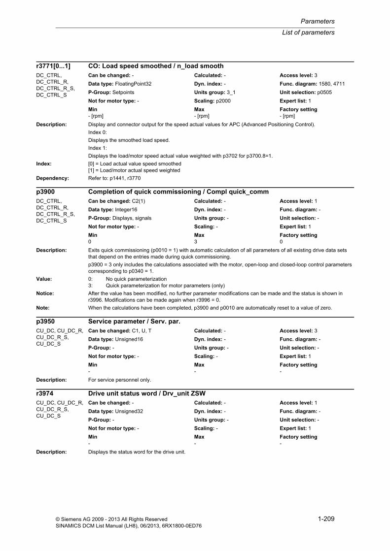
List of parameters
Parameters
1-209© Siemens AG 2009 - 2013 All Rights ReservedSINAMICS DCM List Manual (LH8), 06/2013, 6RX1800-0ED76
Description: Display and connector output for the speed actual values for APC (Advanced Positioning Control).
Index 0:
Displays the smoothed load speed.
Index 1:
Displays the load/motor speed actual value weighted with p3702 for p3700.8=1.
Index: [0] = Load actual value speed smoothed[1] = Load/motor actual speed weighted
Dependency: Refer to: p1441, r3770
Description: Exits quick commissioning (p0010 = 1) with automatic calculation of all parameters of all existing drive data sets that depend on the entries made during quick commissioning.
p3900 = 3 only includes the calculations associated with the motor, open-loop and closed-loop control parameters corresponding to p0340 = 1.
Value: 0: No quick parameterization3: Quick parameterization for motor parameters (only)
Notice: After the value has been modified, no further parameter modifications can be made and the status is shown in r3996. Modifications can be made again when r3996 = 0.
Note: When the calculations have been completed, p3900 and p0010 are automatically reset to a value of zero.
Description: For service personnel only.
Description: Displays the status word for the drive unit.
r3771[0...1] CO: Load speed smoothed / n_load smoothDC_CTRL, DC_CTRL_R, DC_CTRL_R_S, DC_CTRL_S
Can be changed: - Calculated: - Access level: 3
Data type: FloatingPoint32 Dyn. index: - Func. diagram: 1580, 4711
P-Group: Setpoints Units group: 3_1 Unit selection: p0505
Not for motor type: - Scaling: p2000 Expert list: 1
Min Max Factory setting - [rpm] - [rpm] - [rpm]
p3900 Completion of quick commissioning / Compl quick_commDC_CTRL, DC_CTRL_R, DC_CTRL_R_S, DC_CTRL_S
Can be changed: C2(1) Calculated: - Access level: 1
Data type: Integer16 Dyn. index: - Func. diagram: -
P-Group: Displays, signals Units group: - Unit selection: -
Not for motor type: - Scaling: - Expert list: 1
Min Max Factory setting 0 3 0
p3950 Service parameter / Serv. par.CU_DC, CU_DC_R, CU_DC_R_S, CU_DC_S
Can be changed: C1, U, T Calculated: - Access level: 3
Data type: Unsigned16 Dyn. index: - Func. diagram: -
P-Group: - Units group: - Unit selection: -
Not for motor type: - Scaling: - Expert list: 1
Min Max Factory setting - - -
r3974 Drive unit status word / Drv_unit ZSWCU_DC, CU_DC_R, CU_DC_R_S, CU_DC_S
Can be changed: - Calculated: - Access level: 1
Data type: Unsigned32 Dyn. index: - Func. diagram: -
P-Group: - Units group: - Unit selection: -
Not for motor type: - Scaling: - Expert list: 1
Min Max Factory setting - - -
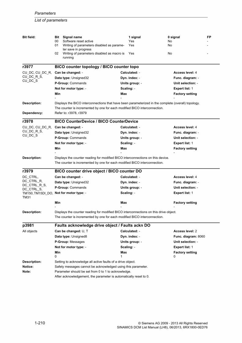
Parameters
List of parameters
1-210 © Siemens AG 2009 - 2013 All Rights ReservedSINAMICS DCM List Manual (LH8), 06/2013, 6RX1800-0ED76
Description: Displays the BICO interconnections that have been parameterized in the complete (overall) topology.
The counter is incremented by one for each modified BICO interconnection.
Dependency: Refer to: r3978, r3979
Description: Displays the counter reading for modified BICO interconnections on this device.
The counter is incremented by one for each modified BICO interconnection.
Description: Displays the counter reading for modified BICO interconnections on this drive object.
The counter is incremented by one for each modified BICO interconnection.
Description: Setting to acknowledge all active faults of a drive object.
Notice: Safety messages cannot be acknowledged using this parameter.
Note: Parameter should be set from 0 to 1 to acknowledge.
After acknowledgement, the parameter is automatically reset to 0.
Bit field: Bit Signal name 1 signal 0 signal FP00 Software reset active Yes No -01 Writing of parameters disabled as parame-
ter save in progressYes No -
02 Writing of parameters disabled as macro is running
Yes No -
r3977 BICO counter topology / BICO counter topoCU_DC, CU_DC_R, CU_DC_R_S, CU_DC_S
Can be changed: - Calculated: - Access level: 4
Data type: Unsigned32 Dyn. index: - Func. diagram: -
P-Group: Commands Units group: - Unit selection: -
Not for motor type: - Scaling: - Expert list: 1
Min Max Factory setting - - -
r3978 BICO CounterDevice / BICO CounterDeviceCU_DC, CU_DC_R, CU_DC_R_S, CU_DC_S
Can be changed: - Calculated: - Access level: 4
Data type: Unsigned32 Dyn. index: - Func. diagram: -
P-Group: Commands Units group: - Unit selection: -
Not for motor type: - Scaling: - Expert list: 1
Min Max Factory setting - - -
r3979 BICO counter drive object / BICO counter DODC_CTRL, DC_CTRL_R, DC_CTRL_R_S, DC_CTRL_S, TM150, TM15DI_DO, TM31
Can be changed: - Calculated: - Access level: 4
Data type: Unsigned32 Dyn. index: - Func. diagram: -
P-Group: Commands Units group: - Unit selection: -
Not for motor type: - Scaling: - Expert list: 1
Min Max Factory setting - - -
p3981 Faults acknowledge drive object / Faults ackn DOAll objects Can be changed: U, T Calculated: - Access level: 2
Data type: Unsigned8 Dyn. index: - Func. diagram: 8060
P-Group: Messages Units group: - Unit selection: -
Not for motor type: - Scaling: - Expert list: 1
Min Max Factory setting 0 1 0

List of parameters
Parameters
1-211© Siemens AG 2009 - 2013 All Rights ReservedSINAMICS DCM List Manual (LH8), 06/2013, 6RX1800-0ED76
Description: Sets the mode to change over the master control / LOCAL mode.
Value: 0: Change master control for STW1.0 = 01: Change master control in operation
Danger: When changing the master control in operation, the drive can manifest undesirable behavior - e.g. it can accelerate up to another setpoint.
Description: Displays the number of parameters for this drive unit.
The number comprises the device-specific and the drive-specific parameters.
Dependency: Refer to: r0980, r0981, r0989
Description: Index 0:
Displays the boot state.
Index 1:
Displays the partial boot state
Value: 0: Not active1: Fatal fault10: Fault20: Reset all parameters30: Drive object modified40: Download using commissioning software50: Parameter download using commissioning software90: Reset Control Unit and delete drive objects100: Start initialization110: Instantiate Control Unit basis150: Wait until actual topology determined160: Evaluate topology170: Instantiate Control Unit reset180: Initialization YDB configuration information200: First commissioning210: Create drive packages250: Wait for topology acknowledge325: Wait for input of drive type
p3985 Master control mode selection / PcCtrl mode selectDC_CTRL, DC_CTRL_R, DC_CTRL_R_S, DC_CTRL_S
Can be changed: U, T Calculated: - Access level: 3
Data type: Integer16 Dyn. index: - Func. diagram: -
P-Group: Setpoints Units group: - Unit selection: -
Not for motor type: - Scaling: - Expert list: 1
Min Max Factory setting 0 1 0
r3986 Parameter count / Parameter No.All objects Can be changed: - Calculated: - Access level: 3
Data type: Unsigned16 Dyn. index: - Func. diagram: -
P-Group: - Units group: - Unit selection: -
Not for motor type: - Scaling: - Expert list: 1
Min Max Factory setting - - -
r3988[0...1] Boot state / Boot_stateCU_DC, CU_DC_R, CU_DC_R_S, CU_DC_S
Can be changed: - Calculated: - Access level: 3
Data type: Integer16 Dyn. index: - Func. diagram: -
P-Group: - Units group: - Unit selection: -
Not for motor type: - Scaling: - Expert list: 1
Min Max Factory setting 0 10800 -

Parameters
List of parameters
1-212 © Siemens AG 2009 - 2013 All Rights ReservedSINAMICS DCM List Manual (LH8), 06/2013, 6RX1800-0ED76
350: Determine drive type360: Write into topology-dependent parameters370: Wait until p0009 = 0 is set380: Check topology550: Call conversion functions for parameter625: Wait non-cyclic starting DRIVE-CLiQ650: Start cyclic operation660: Evaluate drive commissioning status670: Autom. FW update DRIVE-CLiQ components680: Wait for CU LINK slaves690: Wait non-cyclic starting DRIVE-CLiQ700: Save parameters725: Wait until DRIVE-CLiQ cyclic740: Check the ability to operate745: Start of the time slices750: Interrupt enable800: Initialization finished10050: Wait for synchronization10100: Wait for CU LINK slaves10150: Wait until actual topology determined10200: Evaluation component status10250: Call conversion functions for parameter10300: Preparation cyclic operation10350: Autom. FW update DRIVE-CLiQ components10400: Wait for slave properties10450: Check CX/NX status10500: Wait until DRIVE-CLiQ cyclic10550: Carry out warm start10600: Evaluate, encoder status10800: Partial boot completed
Index: [0] = System[1] = Partial boot
Description: Displays whether writing to parameters is inhibited.
r3996[0] = 0:
Parameter write not inhibited.
0 < r3996[0] < 100:
Parameter write inhibited. The value shows how the calculations are progressing.
Index: [0] = Progress calculations[1] = Cause
Note: Re index 1:
Only for internal Siemens troubleshooting.
r3996[0...1] Parameter write inhibit status / Par_write inhib stAll objects Can be changed: - Calculated: - Access level: 1
Data type: Unsigned8 Dyn. index: - Func. diagram: -
P-Group: - Units group: - Unit selection: -
Not for motor type: - Scaling: - Expert list: 1
Min Max Factory setting - - -

List of parameters
Parameters
1-213© Siemens AG 2009 - 2013 All Rights ReservedSINAMICS DCM List Manual (LH8), 06/2013, 6RX1800-0ED76
Description: Displays the actual value at the digital inputs.
This means that the actual input signal can be checked at terminal DI x or DI/DO x prior to switching from the simu-lation mode (p4095.x = 1) to terminal mode (p4095.x = 0).
Note: If a DI/DO is parameterized as output (p4028.x = 1), then r4021.x = 0 is displayed.
DI/DO: Bidirectional Digital Input/Output
Description: Displays the actual value at the digital inputs.
This means that the actual input signal can be checked at terminal DI x or DI/DO x prior to switching from the simu-lation mode (p4095.x = 1) to terminal mode (p4095.x = 0).
r4021 TM15DI/DO digital inputs terminal actual value / TM15D DI act valTM15DI_DO Can be changed: - Calculated: - Access level: 2
Data type: Unsigned32 Dyn. index: - Func. diagram: 9400, 9401, 9402
P-Group: Commands Units group: - Unit selection: -
Not for motor type: - Scaling: - Expert list: 1
Min Max Factory setting - - -
Bit field: Bit Signal name 1 signal 0 signal FP00 DI/DO 0 (X520.2) High Low -01 DI/DO 1 (X520.3) High Low -02 DI/DO 2 (X520.4) High Low -03 DI/DO 3 (X520.5) High Low -04 DI/DO 4 (X520.6) High Low -05 DI/DO 5 (X520.7) High Low -06 DI/DO 6 (X520.8) High Low -07 DI/DO 7 (X520.9) High Low -08 DI/DO 8 (X521.2) High Low -09 DI/DO 9 (X521.3) High Low -10 DI/DO 10 (X521.4) High Low -11 DI/DO 11 (X521.5) High Low -12 DI/DO 12 (X521.6) High Low -13 DI/DO 13 (X521.7) High Low -14 DI/DO 14 (X521.8) High Low -15 DI/DO 15 (X521.9) High Low -16 DI/DO 16 (X522.2) High Low -17 DI/DO 17 (X522.3) High Low -18 DI/DO 18 (X522.4) High Low -19 DI/DO 19 (X522.5) High Low -20 DI/DO 20 (X522.6) High Low -21 DI/DO 21 (X522.7) High Low -22 DI/DO 22 (X522.8) High Low -23 DI/DO 23 (X522.9) High Low -
r4021 TM31 digital inputs terminal actual value / TM31 DI act valueTM31 Can be changed: - Calculated: - Access level: 2
Data type: Unsigned32 Dyn. index: - Func. diagram: 1840, 9550, 9552, 9560, 9562
P-Group: Commands Units group: - Unit selection: -
Not for motor type: - Scaling: - Expert list: 1
Min Max Factory setting - - -
Bit field: Bit Signal name 1 signal 0 signal FP00 DI 0 (X520.1) High Low -01 DI 1 (X520.2) High Low -02 DI 2 (X520.3) High Low -03 DI 3 (X520.4) High Low -04 DI 4 (X530.1) High Low -05 DI 5 (X530.2) High Low -

Parameters
List of parameters
1-214 © Siemens AG 2009 - 2013 All Rights ReservedSINAMICS DCM List Manual (LH8), 06/2013, 6RX1800-0ED76
Note: If a DI/DO is parameterized as output (p4028.x = 1), then r4021.x = 0 is displayed.
DI: Digital Input
DI/DO: Bidirectional Digital Input/Output
Description: Displays the status of the digital inputs of Terminal Module 15 (TM15).
Dependency: Refer to: r4023, r4024, r4025
Notice: For the BICO interconnection of the connector output (CO) only bit 00 ... 15 are transferred.
Note: DI/DO: Bidirectional Digital Input/Output
Description: Displays the status of the digital inputs of Terminal Module 31 (TM31).
06 DI 6 (X530.3) High Low -07 DI 7 (X530.4) High Low -08 DI/DO 8 (X541.2) High Low -09 DI/DO 9 (X541.3) High Low -10 DI/DO 10 (X541.4) High Low -11 DI/DO 11 (X541.5) High Low -
r4022.0...23 CO/BO: TM15DI/DO digital inputs status / TM15D DI statusTM15DI_DO Can be changed: - Calculated: - Access level: 1
Data type: Unsigned32 Dyn. index: - Func. diagram: 1781, 9400, 9401, 9402
P-Group: Commands Units group: - Unit selection: -
Not for motor type: - Scaling: - Expert list: 1
Min Max Factory setting - - -
Bit field: Bit Signal name 1 signal 0 signal FP00 DI/DO 0 (X520.2) High Low -01 DI/DO 1 (X520.3) High Low -02 DI/DO 2 (X520.4) High Low -03 DI/DO 3 (X520.5) High Low -04 DI/DO 4 (X520.6) High Low -05 DI/DO 5 (X520.7) High Low -06 DI/DO 6 (X520.8) High Low -07 DI/DO 7 (X520.9) High Low -08 DI/DO 8 (X521.2) High Low -09 DI/DO 9 (X521.3) High Low -10 DI/DO 10 (X521.4) High Low -11 DI/DO 11 (X521.5) High Low -12 DI/DO 12 (X521.6) High Low -13 DI/DO 13 (X521.7) High Low -14 DI/DO 14 (X521.8) High Low -15 DI/DO 15 (X521.9) High Low -16 DI/DO 16 (X522.2) High Low -17 DI/DO 17 (X522.3) High Low -18 DI/DO 18 (X522.4) High Low -19 DI/DO 19 (X522.5) High Low -20 DI/DO 20 (X522.6) High Low -21 DI/DO 21 (X522.7) High Low -22 DI/DO 22 (X522.8) High Low -23 DI/DO 23 (X522.9) High Low -
r4022.0...11 CO/BO: TM31 digital inputs status / TM31 DI statusTM31 Can be changed: - Calculated: - Access level: 1
Data type: Unsigned32 Dyn. index: - Func. diagram: 1840, 9550, 9552, 9560, 9562
P-Group: Commands Units group: - Unit selection: -
Not for motor type: - Scaling: - Expert list: 1
Min Max Factory setting - - -

List of parameters
Parameters
1-215© Siemens AG 2009 - 2013 All Rights ReservedSINAMICS DCM List Manual (LH8), 06/2013, 6RX1800-0ED76
Dependency: Refer to: r4023
Note: DI: Digital Input
DI/DO: Bidirectional Digital Input/Output
Description: Displays the inverted status of the digital inputs of Terminal Module 15 (TM15).
Dependency: Refer to: r4022, r4024, r4025
Notice: For the BICO interconnection of the connector output (CO) only bit 00 ... 15 are transferred.
Note: DI/DO: Bidirectional Digital Input/Output
Bit field: Bit Signal name 1 signal 0 signal FP00 DI 0 (X520.1) High Low -01 DI 1 (X520.2) High Low -02 DI 2 (X520.3) High Low -03 DI 3 (X520.4) High Low -04 DI 4 (X530.1) High Low -05 DI 5 (X530.2) High Low -06 DI 6 (X530.3) High Low -07 DI 7 (X530.4) High Low -08 DI/DO 8 (X541.2) High Low -09 DI/DO 9 (X541.3) High Low -10 DI/DO 10 (X541.4) High Low -11 DI/DO 11 (X541.5) High Low -
r4023.0...23 CO/BO: TM15DI/DO digital inputs status inverted / TM15D DI stat invTM15DI_DO Can be changed: - Calculated: - Access level: 1
Data type: Unsigned32 Dyn. index: - Func. diagram: 1781, 9400, 9401, 9402
P-Group: Commands Units group: - Unit selection: -
Not for motor type: - Scaling: - Expert list: 1
Min Max Factory setting - - -
Bit field: Bit Signal name 1 signal 0 signal FP00 DI/DO 0 (X520.2) High Low -01 DI/DO 1 (X520.3) High Low -02 DI/DO 2 (X520.4) High Low -03 DI/DO 3 (X520.5) High Low -04 DI/DO 4 (X520.6) High Low -05 DI/DO 5 (X520.7) High Low -06 DI/DO 6 (X520.8) High Low -07 DI/DO 7 (X520.9) High Low -08 DI/DO 8 (X521.2) High Low -09 DI/DO 9 (X521.3) High Low -10 DI/DO 10 (X521.4) High Low -11 DI/DO 11 (X521.5) High Low -12 DI/DO 12 (X521.6) High Low -13 DI/DO 13 (X521.7) High Low -14 DI/DO 14 (X521.8) High Low -15 DI/DO 15 (X521.9) High Low -16 DI/DO 16 (X522.2) High Low -17 DI/DO 17 (X522.3) High Low -18 DI/DO 18 (X522.4) High Low -19 DI/DO 19 (X522.5) High Low -20 DI/DO 20 (X522.6) High Low -21 DI/DO 21 (X522.7) High Low -22 DI/DO 22 (X522.8) High Low -23 DI/DO 23 (X522.9) High Low -

Parameters
List of parameters
1-216 © Siemens AG 2009 - 2013 All Rights ReservedSINAMICS DCM List Manual (LH8), 06/2013, 6RX1800-0ED76
Description: Displays the inverted status of the digital inputs of Terminal Module 31 (TM31).
Dependency: Refer to: r4022
Note: DI: Digital Input
DI/DO: Bidirectional Digital Input/Output
Description: Displays the status of digital inputs 16 ... 23 of Terminal Module 15 (TM15).
Dependency: Refer to: r4022, r4023, r4025
Note: DI: Digital Input
Description: Displays the inverted status of digital inputs 16 ... 23 of Terminal Module 15 (TM15).
r4023.0...11 CO/BO: TM31 digital inputs status inverted / TM31 DI status invTM31 Can be changed: - Calculated: - Access level: 1
Data type: Unsigned32 Dyn. index: - Func. diagram: 1840, 9550, 9552, 9560, 9562
P-Group: Commands Units group: - Unit selection: -
Not for motor type: - Scaling: - Expert list: 1
Min Max Factory setting - - -
Bit field: Bit Signal name 1 signal 0 signal FP00 DI 0 (X520.1) High Low -01 DI 1 (X520.2) High Low -02 DI 2 (X520.3) High Low -03 DI 3 (X520.4) High Low -04 DI 4 (X530.1) High Low -05 DI 5 (X530.2) High Low -06 DI 6 (X530.3) High Low -07 DI 7 (X530.4) High Low -08 DI/DO 8 (X541.2) High Low -09 DI/DO 9 (X541.3) High Low -10 DI/DO 10 (X541.4) High Low -11 DI/DO 11 (X541.5) High Low -
r4024 CO: TM15DI/DO digital inputs 16 ... 23 status / TM15D DI 16-23 StTM15DI_DO Can be changed: - Calculated: - Access level: 1
Data type: Unsigned16 Dyn. index: - Func. diagram: 9402
P-Group: Commands Units group: - Unit selection: -
Not for motor type: - Scaling: - Expert list: 1
Min Max Factory setting - - -
Bit field: Bit Signal name 1 signal 0 signal FP00 DI/DO 16 (X522.2) ON OFF -01 DI/DO 17 (X522.3) ON OFF -02 DI/DO 18 (X522.4) ON OFF -03 DI/DO 19 (X522.5) ON OFF -04 DI/DO 20 (X522.6) ON OFF -05 DI/DO 21 (X522.7) ON OFF -06 DI/DO 22 (X522.8) ON OFF -07 DI/DO 23 (X522.9) ON OFF -
r4025 CO: TM15DI/DO digital inputs 16 ... 23 status inverted / TM15D DI 16-23 invTM15DI_DO Can be changed: - Calculated: - Access level: 1
Data type: Unsigned16 Dyn. index: - Func. diagram: 9402
P-Group: Commands Units group: - Unit selection: -
Not for motor type: - Scaling: - Expert list: 1
Min Max Factory setting - - -
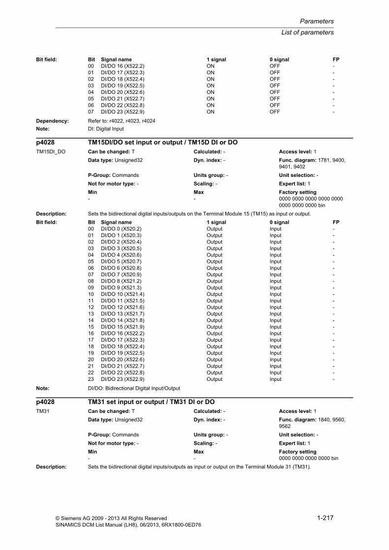
List of parameters
Parameters
1-217© Siemens AG 2009 - 2013 All Rights ReservedSINAMICS DCM List Manual (LH8), 06/2013, 6RX1800-0ED76
Dependency: Refer to: r4022, r4023, r4024
Note: DI: Digital Input
Description: Sets the bidirectional digital inputs/outputs on the Terminal Module 15 (TM15) as input or output.
Note: DI/DO: Bidirectional Digital Input/Output
Description: Sets the bidirectional digital inputs/outputs as input or output on the Terminal Module 31 (TM31).
Bit field: Bit Signal name 1 signal 0 signal FP00 DI/DO 16 (X522.2) ON OFF -01 DI/DO 17 (X522.3) ON OFF -02 DI/DO 18 (X522.4) ON OFF -03 DI/DO 19 (X522.5) ON OFF -04 DI/DO 20 (X522.6) ON OFF -05 DI/DO 21 (X522.7) ON OFF -06 DI/DO 22 (X522.8) ON OFF -07 DI/DO 23 (X522.9) ON OFF -
p4028 TM15DI/DO set input or output / TM15D DI or DOTM15DI_DO Can be changed: T Calculated: - Access level: 1
Data type: Unsigned32 Dyn. index: - Func. diagram: 1781, 9400, 9401, 9402
P-Group: Commands Units group: - Unit selection: -
Not for motor type: - Scaling: - Expert list: 1
Min Max Factory setting - - 0000 0000 0000 0000 0000
0000 0000 0000 bin
Bit field: Bit Signal name 1 signal 0 signal FP00 DI/DO 0 (X520.2) Output Input -01 DI/DO 1 (X520.3) Output Input -02 DI/DO 2 (X520.4) Output Input -03 DI/DO 3 (X520.5) Output Input -04 DI/DO 4 (X520.6) Output Input -05 DI/DO 5 (X520.7) Output Input -06 DI/DO 6 (X520.8) Output Input -07 DI/DO 7 (X520.9) Output Input -08 DI/DO 8 (X521.2) Output Input -09 DI/DO 9 (X521.3) Output Input -10 DI/DO 10 (X521.4) Output Input -11 DI/DO 11 (X521.5) Output Input -12 DI/DO 12 (X521.6) Output Input -13 DI/DO 13 (X521.7) Output Input -14 DI/DO 14 (X521.8) Output Input -15 DI/DO 15 (X521.9) Output Input -16 DI/DO 16 (X522.2) Output Input -17 DI/DO 17 (X522.3) Output Input -18 DI/DO 18 (X522.4) Output Input -19 DI/DO 19 (X522.5) Output Input -20 DI/DO 20 (X522.6) Output Input -21 DI/DO 21 (X522.7) Output Input -22 DI/DO 22 (X522.8) Output Input -23 DI/DO 23 (X522.9) Output Input -
p4028 TM31 set input or output / TM31 DI or DOTM31 Can be changed: T Calculated: - Access level: 1
Data type: Unsigned32 Dyn. index: - Func. diagram: 1840, 9560, 9562
P-Group: Commands Units group: - Unit selection: -
Not for motor type: - Scaling: - Expert list: 1
Min Max Factory setting - - 0000 0000 0000 0000 bin

Parameters
List of parameters
1-218 © Siemens AG 2009 - 2013 All Rights ReservedSINAMICS DCM List Manual (LH8), 06/2013, 6RX1800-0ED76
Note: DI/DO: Bidirectional Digital Input/Output
Description: Sets the signal source for terminal DI/DO 0 (X520.2) of Terminal Module 15 (TM15).
Note: Prerequisite: The DI/DO must be set as an output (p4028.0 = 1).
DI/DO: Bidirectional Digital Input/Output
Description: Sets the signal source for the digital output DO 0 (X542.1, X542.2, X542.3) of Terminal Module 31 (TM31).
Digital output 0 of TM31 is a relay output.
If the signal at the binector input p4030 is low, then terminal COM 0 (X542.2) is connected to NC 0 (X542.1). This connection also matches the mechanical quiescent setting of the relay.
If the signal at the binector input p4030 is high, then terminal COM 0 (X542.2) is connected to NO 0 (X542.3).
Note: DO: Digital Output
NC: Normally Closed contact
NO: Normally Open contact
Description: Sets the signal source for terminal DI/DO 1 (X520.3) of Terminal Module 15 (TM15).
Note: Prerequisite: The DI/DO must be set as an output (p4028.1 = 1).
DI/DO: Bidirectional Digital Input/Output
Description: Sets the signal source for the digital output DO 1 (X542.4, X542.5, X542.6) of Terminal Module 31 (TM31).
Bit field: Bit Signal name 1 signal 0 signal FP08 DI/DO 8 (X541.2) Output Input -09 DI/DO 9 (X541.3) Output Input -10 DI/DO 10 (X541.4) Output Input -11 DI/DO 11 (X541.5) Output Input -
p4030 BI: TM15DI/DO signal source for terminal DI/DO 0 / TM15D S_src DI/DO0TM15DI_DO Can be changed: U, T Calculated: - Access level: 1
Data type: Unsigned32 / Binary Dyn. index: - Func. diagram: 1781, 9400
P-Group: Commands Units group: - Unit selection: -
Not for motor type: - Scaling: - Expert list: 1
Min Max Factory setting - - 0
p4030 BI: TM31 signal source for terminal DO 0 / TM31 s s DO 0TM31 Can be changed: U, T Calculated: - Access level: 1
Data type: Unsigned32 / Binary Dyn. index: - Func. diagram: 1840, 9556
P-Group: Commands Units group: - Unit selection: -
Not for motor type: - Scaling: - Expert list: 1
Min Max Factory setting - - 0
p4031 BI: TM15DI/DO signal source for terminal DI/DO 1 / TM15D S_src DI/DO1TM15DI_DO Can be changed: U, T Calculated: - Access level: 1
Data type: Unsigned32 / Binary Dyn. index: - Func. diagram: 9400
P-Group: Commands Units group: - Unit selection: -
Not for motor type: - Scaling: - Expert list: 1
Min Max Factory setting - - 0
p4031 BI: TM31 signal source for terminal DO 1 / TM31 s s DO 1TM31 Can be changed: U, T Calculated: - Access level: 1
Data type: Unsigned32 / Binary Dyn. index: - Func. diagram: 1840, 9556
P-Group: Commands Units group: - Unit selection: -
Not for motor type: - Scaling: - Expert list: 1
Min Max Factory setting - - 0
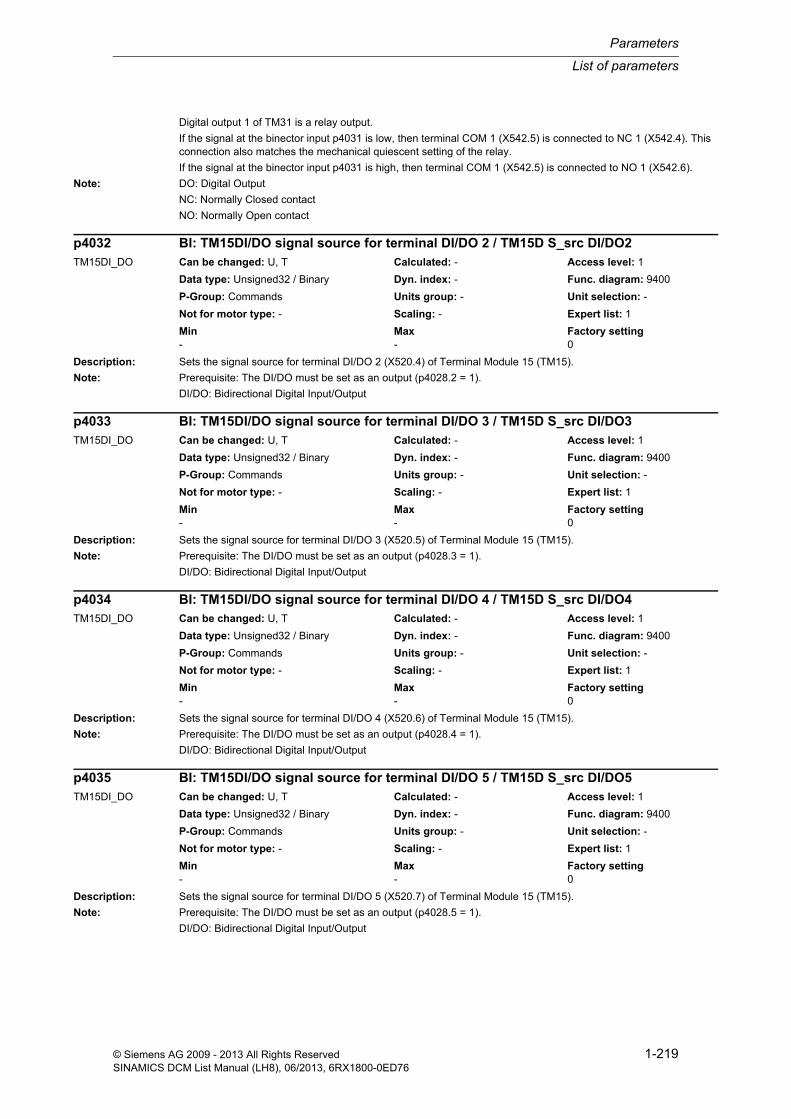
List of parameters
Parameters
1-219© Siemens AG 2009 - 2013 All Rights ReservedSINAMICS DCM List Manual (LH8), 06/2013, 6RX1800-0ED76
Digital output 1 of TM31 is a relay output.
If the signal at the binector input p4031 is low, then terminal COM 1 (X542.5) is connected to NC 1 (X542.4). This connection also matches the mechanical quiescent setting of the relay.
If the signal at the binector input p4031 is high, then terminal COM 1 (X542.5) is connected to NO 1 (X542.6).
Note: DO: Digital Output
NC: Normally Closed contact
NO: Normally Open contact
Description: Sets the signal source for terminal DI/DO 2 (X520.4) of Terminal Module 15 (TM15).
Note: Prerequisite: The DI/DO must be set as an output (p4028.2 = 1).
DI/DO: Bidirectional Digital Input/Output
Description: Sets the signal source for terminal DI/DO 3 (X520.5) of Terminal Module 15 (TM15).
Note: Prerequisite: The DI/DO must be set as an output (p4028.3 = 1).
DI/DO: Bidirectional Digital Input/Output
Description: Sets the signal source for terminal DI/DO 4 (X520.6) of Terminal Module 15 (TM15).
Note: Prerequisite: The DI/DO must be set as an output (p4028.4 = 1).
DI/DO: Bidirectional Digital Input/Output
Description: Sets the signal source for terminal DI/DO 5 (X520.7) of Terminal Module 15 (TM15).
Note: Prerequisite: The DI/DO must be set as an output (p4028.5 = 1).
DI/DO: Bidirectional Digital Input/Output
p4032 BI: TM15DI/DO signal source for terminal DI/DO 2 / TM15D S_src DI/DO2TM15DI_DO Can be changed: U, T Calculated: - Access level: 1
Data type: Unsigned32 / Binary Dyn. index: - Func. diagram: 9400
P-Group: Commands Units group: - Unit selection: -
Not for motor type: - Scaling: - Expert list: 1
Min Max Factory setting - - 0
p4033 BI: TM15DI/DO signal source for terminal DI/DO 3 / TM15D S_src DI/DO3TM15DI_DO Can be changed: U, T Calculated: - Access level: 1
Data type: Unsigned32 / Binary Dyn. index: - Func. diagram: 9400
P-Group: Commands Units group: - Unit selection: -
Not for motor type: - Scaling: - Expert list: 1
Min Max Factory setting - - 0
p4034 BI: TM15DI/DO signal source for terminal DI/DO 4 / TM15D S_src DI/DO4TM15DI_DO Can be changed: U, T Calculated: - Access level: 1
Data type: Unsigned32 / Binary Dyn. index: - Func. diagram: 9400
P-Group: Commands Units group: - Unit selection: -
Not for motor type: - Scaling: - Expert list: 1
Min Max Factory setting - - 0
p4035 BI: TM15DI/DO signal source for terminal DI/DO 5 / TM15D S_src DI/DO5TM15DI_DO Can be changed: U, T Calculated: - Access level: 1
Data type: Unsigned32 / Binary Dyn. index: - Func. diagram: 9400
P-Group: Commands Units group: - Unit selection: -
Not for motor type: - Scaling: - Expert list: 1
Min Max Factory setting - - 0
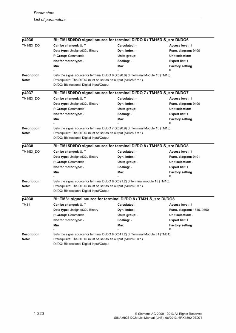
Parameters
List of parameters
1-220 © Siemens AG 2009 - 2013 All Rights ReservedSINAMICS DCM List Manual (LH8), 06/2013, 6RX1800-0ED76
Description: Sets the signal source for terminal DI/DO 6 (X520.8) of Terminal Module 15 (TM15).
Note: Prerequisite: The DI/DO must be set as an output (p4028.6 = 1).
DI/DO: Bidirectional Digital Input/Output
Description: Sets the signal source for terminal DI/DO 7 (X520.9) of Terminal Module 15 (TM15).
Note: Prerequisite: The DI/DO must be set as an output (p4028.7 = 1).
DI/DO: Bidirectional Digital Input/Output
Description: Sets the signal source for terminal DI/DO 8 (X521.2) of terminal module 15 (TM15).
Note: Prerequisite: The DI/DO must be set as an output (p4028.8 = 1).
DI/DO: Bidirectional Digital Input/Output
Description: Sets the signal source for terminal DI/DO 8 (X541.2) of Terminal Module 31 (TM31).
Note: Prerequisite: The DI/DO must be set as an output (p4028.8 = 1).
DI/DO: Bidirectional Digital Input/Output
p4036 BI: TM15DI/DO signal source for terminal DI/DO 6 / TM15D S_src DI/DO6TM15DI_DO Can be changed: U, T Calculated: - Access level: 1
Data type: Unsigned32 / Binary Dyn. index: - Func. diagram: 9400
P-Group: Commands Units group: - Unit selection: -
Not for motor type: - Scaling: - Expert list: 1
Min Max Factory setting - - 0
p4037 BI: TM15DI/DO signal source for terminal DI/DO 7 / TM15D S_src DI/DO7TM15DI_DO Can be changed: U, T Calculated: - Access level: 1
Data type: Unsigned32 / Binary Dyn. index: - Func. diagram: 9400
P-Group: Commands Units group: - Unit selection: -
Not for motor type: - Scaling: - Expert list: 1
Min Max Factory setting - - 0
p4038 BI: TM15DI/DO signal source for terminal DI/DO 8 / TM15D S_src DI/DO8TM15DI_DO Can be changed: U, T Calculated: - Access level: 1
Data type: Unsigned32 / Binary Dyn. index: - Func. diagram: 9401
P-Group: Commands Units group: - Unit selection: -
Not for motor type: - Scaling: - Expert list: 1
Min Max Factory setting - - 0
p4038 BI: TM31 signal source for terminal DI/DO 8 / TM31 S_src DI/DO8TM31 Can be changed: U, T Calculated: - Access level: 1
Data type: Unsigned32 / Binary Dyn. index: - Func. diagram: 1840, 9560
P-Group: Commands Units group: - Unit selection: -
Not for motor type: - Scaling: - Expert list: 1
Min Max Factory setting - - 0

List of parameters
Parameters
1-221© Siemens AG 2009 - 2013 All Rights ReservedSINAMICS DCM List Manual (LH8), 06/2013, 6RX1800-0ED76
Description: Sets the signal source for terminal DI/DO 9 (X521.3) of Terminal Module 15 (TM15).
Note: Prerequisite: The DI/DO must be set as an output (p4028.9 = 1).
DI/DO: Bidirectional Digital Input/Output
Description: Sets the signal source for terminal DI/DO 9 (X541.3) of Terminal Module 31 (TM31).
Note: Prerequisite: The DI/DO must be set as an output (p4028.9 = 1).
DI/DO: Bidirectional Digital Input/Output
Description: Sets the signal source for terminal DI/DO 10 (X521.4) of Terminal Module 15 (TM15).
Note: Prerequisite: The DI/DO must be set as an output (p4028.10 = 1).
DI/DO: Bidirectional Digital Input/Output
Description: Sets the signal source for terminal DI/DO 10 (X541.4) of Terminal Module 31 (TM31).
Note: Prerequisite: The DI/DO must be set as an output (p4028.10 = 1).
DI/DO: Bidirectional Digital Input/Output
p4039 BI: TM15DI/DO signal source for terminal DI/DO 9 / TM15D S_src DI/DO9TM15DI_DO Can be changed: U, T Calculated: - Access level: 1
Data type: Unsigned32 / Binary Dyn. index: - Func. diagram: 9401
P-Group: Commands Units group: - Unit selection: -
Not for motor type: - Scaling: - Expert list: 1
Min Max Factory setting - - 0
p4039 BI: TM31 signal source for terminal DI/DO 9 / TM31 S_src DI/DO9TM31 Can be changed: U, T Calculated: - Access level: 1
Data type: Unsigned32 / Binary Dyn. index: - Func. diagram: 9560
P-Group: Commands Units group: - Unit selection: -
Not for motor type: - Scaling: - Expert list: 1
Min Max Factory setting - - 0
p4040 BI: TM15DI/DO signal source for terminal DI/DO 10 / TM15D S_srcDI/DO10TM15DI_DO Can be changed: U, T Calculated: - Access level: 1
Data type: Unsigned32 / Binary Dyn. index: - Func. diagram: 9401
P-Group: Commands Units group: - Unit selection: -
Not for motor type: - Scaling: - Expert list: 1
Min Max Factory setting - - 0
p4040 BI: TM31 signal source for terminal DI/DO 10 / TM31 S_src DI/DO10TM31 Can be changed: U, T Calculated: - Access level: 1
Data type: Unsigned32 / Binary Dyn. index: - Func. diagram: 9562
P-Group: Commands Units group: - Unit selection: -
Not for motor type: - Scaling: - Expert list: 1
Min Max Factory setting - - 0

Parameters
List of parameters
1-222 © Siemens AG 2009 - 2013 All Rights ReservedSINAMICS DCM List Manual (LH8), 06/2013, 6RX1800-0ED76
Description: Sets the signal source for terminal DI/DO 11 (X521.5) of Terminal Module 15 (TM15).
Note: Prerequisite: The DI/DO must be set as an output (p4028.11 = 1).
DI/DO: Bidirectional Digital Input/Output
Description: Sets the signal source for terminal DI/DO 11 (X541.5) of Terminal Module 31 (TM31).
Note: Prerequisite: The DI/DO must be set as an output (p4028.11 = 1).
DI/DO: Bidirectional Digital Input/Output
Description: Sets the signal source for terminal DI/DO 12 (X521.6) of Terminal Module 15 (TM15).
Note: Prerequisite: The DI/DO must be set as an output (p4028.12 = 1).
DI/DO: Bidirectional Digital Input/Output
Description: Sets the signal source for terminal DI/DO 13 (X521.7) of Terminal Module 15 (TM15).
Note: Prerequisite: The DI/DO must be set as an output (p4028.13 = 1).
DI/DO: Bidirectional Digital Input/Output
p4041 BI: TM15DI/DO signal source for terminal DI/DO 11 / TM15D S_srcDI/DO11TM15DI_DO Can be changed: U, T Calculated: - Access level: 1
Data type: Unsigned32 / Binary Dyn. index: - Func. diagram: 9401
P-Group: Commands Units group: - Unit selection: -
Not for motor type: - Scaling: - Expert list: 1
Min Max Factory setting - - 0
p4041 BI: TM31 signal source for terminal DI/DO 11 / TM31 S_src DI/DO11TM31 Can be changed: U, T Calculated: - Access level: 1
Data type: Unsigned32 / Binary Dyn. index: - Func. diagram: 1840, 9562
P-Group: Commands Units group: - Unit selection: -
Not for motor type: - Scaling: - Expert list: 1
Min Max Factory setting - - 0
p4042 BI: TM15DI/DO signal source for terminal DI/DO 12 / TM15D S_srcDI/DO12TM15DI_DO Can be changed: U, T Calculated: - Access level: 1
Data type: Unsigned32 / Binary Dyn. index: - Func. diagram: 9401
P-Group: Commands Units group: - Unit selection: -
Not for motor type: - Scaling: - Expert list: 1
Min Max Factory setting - - 0
p4043 BI: TM15DI/DO signal source for terminal DI/DO 13 / TM15D S_srcDI/DO13TM15DI_DO Can be changed: U, T Calculated: - Access level: 1
Data type: Unsigned32 / Binary Dyn. index: - Func. diagram: 9401
P-Group: Commands Units group: - Unit selection: -
Not for motor type: - Scaling: - Expert list: 1
Min Max Factory setting - - 0
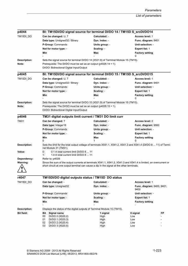
List of parameters
Parameters
1-223© Siemens AG 2009 - 2013 All Rights ReservedSINAMICS DCM List Manual (LH8), 06/2013, 6RX1800-0ED76
Description: Sets the signal source for terminal DI/DO 14 (X521.8) of Terminal Module 15 (TM15).
Note: Prerequisite: The DI/DO must be set as an output (p4028.14 = 1).
DI/DO: Bidirectional Digital Input/Output
Description: Sets the signal source for terminal DI/DO 15 (X521.9) of Terminal Module 15 (TM15).
Note: Prerequisite: The DI/DO must be set as an output (p4028.15 = 1).
DI/DO: Bidirectional Digital Input/Output
Description: Sets the limit for the total output voltage of terminals X541.1, X541.2, X541.3 and X541.4 (DI/DO 8 ... 11) of Termi-nal Module 31 (TM31).
Value: 0: 0.1 A total current limit DI/DO 8 ... 111: 1.0 A total current limit DI/DO 8 ... 11
Dependency: Refer to: p4028
Warning: Since the sum of the output currents at terminals X541.1, X541.2, X541.3 and X541.4 is limited, an overcurrent or short circuit at one output terminal can cause a dip in the signal at the other terminals.
Description: Displays the status of the digital outputs of Terminal Module 15 (TM15).
p4044 BI: TM15DI/DO signal source for terminal DI/DO 14 / TM15D S_srcDI/DO14TM15DI_DO Can be changed: U, T Calculated: - Access level: 1
Data type: Unsigned32 / Binary Dyn. index: - Func. diagram: 9401
P-Group: Commands Units group: - Unit selection: -
Not for motor type: - Scaling: - Expert list: 1
Min Max Factory setting - - 0
p4045 BI: TM15DI/DO signal source for terminal DI/DO 15 / TM15D S_srcDI/DO15TM15DI_DO Can be changed: U, T Calculated: - Access level: 1
Data type: Unsigned32 / Binary Dyn. index: - Func. diagram: 9401
P-Group: Commands Units group: - Unit selection: -
Not for motor type: - Scaling: - Expert list: 1
Min Max Factory setting - - 0
p4046 TM31 digital outputs limit current / TM31 DO limit currTM31 Can be changed: T Calculated: - Access level: 2
Data type: Integer16 Dyn. index: - Func. diagram: 9560
P-Group: Commands Units group: - Unit selection: -
Not for motor type: - Scaling: - Expert list: 1
Min Max Factory setting 0 1 0
r4047 TM15DI/DO digital outputs status / TM15D DO statusTM15DI_DO Can be changed: - Calculated: - Access level: 1
Data type: Unsigned32 Dyn. index: - Func. diagram: 9400, 9401, 9402
P-Group: Commands Units group: - Unit selection: -
Not for motor type: - Scaling: - Expert list: 1
Min Max Factory setting - - -
Bit field: Bit Signal name 1 signal 0 signal FP00 DI/DO 0 (X520.2) High Low -01 DI/DO 1 (X520.3) High Low -02 DI/DO 2 (X520.4) High Low -03 DI/DO 3 (X520.5) High Low -

Parameters
List of parameters
1-224 © Siemens AG 2009 - 2013 All Rights ReservedSINAMICS DCM List Manual (LH8), 06/2013, 6RX1800-0ED76
Note: Inversion using p4048 has been taken into account.
The setting of the DI/DO as either input or output is of no significance (p4028).
DI/DO: Bidirectional Digital Input/Output
Description: Displays the status of the digital outputs of Terminal Module 31 (TM31).
Note: Inversion using p4048 has been taken into account.
The setting of the DI/DO as either input or output is of no significance (p4028).
DO: Digital Output
DI/DO: Bidirectional Digital Input/Output
Description: Setting to invert the signals at the digital outputs of Terminal Module 15 (TM15).
04 DI/DO 4 (X520.6) High Low -05 DI/DO 5 (X520.7) High Low -06 DI/DO 6 (X520.8) High Low -07 DI/DO 7 (X520.9) High Low -08 DI/DO 8 (X521.2) High Low -09 DI/DO 9 (X521.3) High Low -10 DI/DO 10 (X521.4) High Low -11 DI/DO 11 (X521.5) High Low -12 DI/DO 12 (X521.6) High Low -13 DI/DO 13 (X521.7) High Low -14 DI/DO 14 (X521.8) High Low -15 DI/DO 15 (X521.9) High Low -16 DI/DO 16 (X522.2) High Low -17 DI/DO 17 (X522.3) High Low -18 DI/DO 18 (X522.4) High Low -19 DI/DO 19 (X522.5) High Low -20 DI/DO 20 (X522.6) High Low -21 DI/DO 21 (X522.7) High Low -22 DI/DO 22 (X522.8) High Low -23 DI/DO 23 (X522.9) High Low -
r4047 TM31 digital outputs status / TM31 DO statusTM31 Can be changed: - Calculated: - Access level: 1
Data type: Unsigned32 Dyn. index: - Func. diagram: 9556, 9560, 9562
P-Group: Commands Units group: - Unit selection: -
Not for motor type: - Scaling: - Expert list: 1
Min Max Factory setting - - -
Bit field: Bit Signal name 1 signal 0 signal FP00 DO 0 (X542.1 - 3) High Low -01 DO 1 (X542.4 - 6) High Low -08 DI/DO 8 (X541.2) High Low -09 DI/DO 9 (X541.3) High Low -10 DI/DO 10 (X541.4) High Low -11 DI/DO 11 (X541.5) High Low -
p4048 TM15DI/DO invert digital outputs / TM15D DO invTM15DI_DO Can be changed: U, T Calculated: - Access level: 1
Data type: Unsigned32 Dyn. index: - Func. diagram: 9400, 9401, 9402
P-Group: Commands Units group: - Unit selection: -
Not for motor type: - Scaling: - Expert list: 1
Min Max Factory setting - - 0000 0000 0000 0000 0000
0000 0000 0000 bin
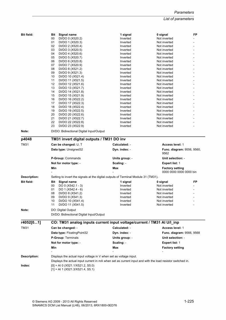
List of parameters
Parameters
1-225© Siemens AG 2009 - 2013 All Rights ReservedSINAMICS DCM List Manual (LH8), 06/2013, 6RX1800-0ED76
Note: DI/DO: Bidirectional Digital Input/Output
Description: Setting to invert the signals at the digital outputs of Terminal Module 31 (TM31).
Note: DO: Digital Output
DI/DO: Bidirectional Digital Input/Output
Description: Displays the actual input voltage in V when set as voltage input.
Displays the actual input current in mA when set as current input and with the load resistor switched in.
Index: [0] = AI 0 (X521.1/X521.2, S5.0)[1] = AI 1 (X521.3/X521.4, S5.1)
Bit field: Bit Signal name 1 signal 0 signal FP00 DI/DO 0 (X520.2) Inverted Not inverted -01 DI/DO 1 (X520.3) Inverted Not inverted -02 DI/DO 2 (X520.4) Inverted Not inverted -03 DI/DO 3 (X520.5) Inverted Not inverted -04 DI/DO 4 (X520.6) Inverted Not inverted -05 DI/DO 5 (X520.7) Inverted Not inverted -06 DI/DO 6 (X520.8) Inverted Not inverted -07 DI/DO 7 (X520.9) Inverted Not inverted -08 DI/DO 8 (X521.2) Inverted Not inverted -09 DI/DO 9 (X521.3) Inverted Not inverted -10 DI/DO 10 (X521.4) Inverted Not inverted -11 DI/DO 11 (X521.5) Inverted Not inverted -12 DI/DO 12 (X521.6) Inverted Not inverted -13 DI/DO 13 (X521.7) Inverted Not inverted -14 DI/DO 14 (X521.8) Inverted Not inverted -15 DI/DO 15 (X521.9) Inverted Not inverted -16 DI/DO 16 (X522.2) Inverted Not inverted -17 DI/DO 17 (X522.3) Inverted Not inverted -18 DI/DO 18 (X522.4) Inverted Not inverted -19 DI/DO 19 (X522.5) Inverted Not inverted -20 DI/DO 20 (X522.6) Inverted Not inverted -21 DI/DO 21 (X522.7) Inverted Not inverted -22 DI/DO 22 (X522.8) Inverted Not inverted -23 DI/DO 23 (X522.9) Inverted Not inverted -
p4048 TM31 invert digital outputs / TM31 DO invTM31 Can be changed: U, T Calculated: - Access level: 1
Data type: Unsigned32 Dyn. index: - Func. diagram: 9556, 9560, 9562
P-Group: Commands Units group: - Unit selection: -
Not for motor type: - Scaling: - Expert list: 1
Min Max Factory setting - - 0000 0000 0000 0000 bin
Bit field: Bit Signal name 1 signal 0 signal FP00 DO 0 (X542.1 - 3) Inverted Not inverted -01 DO 1 (X542.4 - 6) Inverted Not inverted -08 DI/DO 8 (X541.2) Inverted Not inverted -09 DI/DO 9 (X541.3) Inverted Not inverted -10 DI/DO 10 (X541.4) Inverted Not inverted -11 DI/DO 11 (X541.5) Inverted Not inverted -
r4052[0...1] CO: TM31 analog inputs current input voltage/current / TM31 AI U/I_inpTM31 Can be changed: - Calculated: - Access level: 1
Data type: FloatingPoint32 Dyn. index: - Func. diagram: 9566, 9568
P-Group: Terminals Units group: - Unit selection: -
Not for motor type: - Scaling: - Expert list: 1
Min Max Factory setting - - -

Parameters
List of parameters
1-226 © Siemens AG 2009 - 2013 All Rights ReservedSINAMICS DCM List Manual (LH8), 06/2013, 6RX1800-0ED76
Dependency: The type of analog input AI x (voltage or current input) is set using p4056.
Refer to: p4056
Note: AI: Analog Input
Description: Sets the smoothing time constant of the 1st-order low pass filter for the analog inputs of Terminal Module 31 (TM31).
Index: [0] = AI 0 (X521.1/X521.2, S5.0)[1] = AI 1 (X521.3/X521.4, S5.1)
Note: AI: Analog Input
Description: Displays the currently referred input value of the analog inputs of Terminal Module 31 (TM31).
When interconnected, the signals are referred to the reference quantities p200x and p205x.
Index: [0] = AI 0 (X521.1/X521.2, S5.0)[1] = AI 1 (X521.3/X521.4, S5.1)
Note: AI: Analog Input
Description: Sets the type of analog inputs of Terminal Module 31 (TM31).
p4056[x] = 0, 4 correspond to a voltage input (r4052, p4057, p4059 are displayed in V).
p4056[x] = 2, 3, 5 correspond to a current input (r4052, p4057, p4059 are displayed in mA).
In addition, the associated switch S5 must be appropriately set.
AI 0: S5.0 = V --> voltage input, S5.0 = I --> current input (burden resistor = 250 Ohm)
AI 1: S5.1 = V --> voltage input, S5.1 = I --> current input (burden resistor = 250 Ohm)
Value: 0: Unipolar voltage input (0 V ... +10 V)2: Unipolar current input (0 mA ... +20 mA)3: Unipolar current input monitored (+4 mA to +20 mA)4: Bipolar voltage input (-10 V ... +10 V)5: Bipolar current input (-20 mA to +20 mA)
Index: [0] = AI 0 (X521.1/X521.2, S5.0)[1] = AI 1 (X521.3/X521.4, S5.1)
p4053[0...1] TM31 analog inputs smoothing time constant / TM31 AI T_smoothTM31 Can be changed: U, T Calculated: - Access level: 1
Data type: FloatingPoint32 Dyn. index: - Func. diagram: 9566, 9568
P-Group: Terminals Units group: - Unit selection: -
Not for motor type: - Scaling: - Expert list: 1
Min Max Factory setting 0.0 [ms] 1000.0 [ms] 0.0 [ms]
r4055[0...1] CO: TM31 analog inputs actual value in percent / TM31 AI value in %TM31 Can be changed: - Calculated: - Access level: 1
Data type: FloatingPoint32 Dyn. index: - Func. diagram: 1840, 9566, 9568
P-Group: Terminals Units group: - Unit selection: -
Not for motor type: - Scaling: PERCENT Expert list: 1
Min Max Factory setting - [%] - [%] - [%]
p4056[0...1] TM31 analog inputs type / TM31 AI typeTM31 Can be changed: U, T Calculated: - Access level: 1
Data type: Integer16 Dyn. index: - Func. diagram: 9566, 9568
P-Group: Terminals Units group: - Unit selection: -
Not for motor type: - Scaling: - Expert list: 1
Min Max Factory setting 0 5 4

List of parameters
Parameters
1-227© Siemens AG 2009 - 2013 All Rights ReservedSINAMICS DCM List Manual (LH8), 06/2013, 6RX1800-0ED76
Warning: The maximum voltage difference between the analog input terminals AI+, AI- and the ground of the TM31 (X520.6, X530.3) may not exceed 35 V.
For operation with the load resistor switched in, the voltage between the differential inputs AI+ and AI- may not exceed 15 V or the impressed current of 60 mA; if this is not carefully observed, the input will be damaged.
Notice: For operation as a voltage input/current input, switch S5.0 or S5.1 must be appropriately set.
Note: When changing p4056, the parameters of the scaling characteristic (p4057, p4058, p4059, p4060) are overwritten with the following default values:
For p4056 = 0, 4, p4057 is set to 0.0 V, p4058 to 0.0 %, p4059 to 10.0 V and p4060 to 100.0 %.
For p4056 = 2, 5, p4057 is set to 0.0 mA, p4058 to 0.0 %, p4059 to 20.0 mA and p4060 to 100.0 %.
For p4056 = 3, p4057 is set to 4.0 mA, p4058 to 0.0 %, p4059 to 20.0 mA and p4060 to 100.0 %.
Description: Sets the scaling characteristic for the analog inputs of Terminal Module 31 (TM31).
The scaling characteristic for the analog inputs is defined using 2 points.
This parameter specifies the x coordinate (input voltage in V or input current in mA) of the 1st value pair of the char-acteristic.
Index: [0] = AI 0 (X521.1/X521.2, S5.0)[1] = AI 1 (X521.3/X521.4, S5.1)
Dependency: The unit of this parameter (V or mA) depends on the analog input type.
Refer to: p4056
Notice: This parameter is automatically overwritten when the analog input type (p4056) is modified.
Note: The parameters for the characteristic do not have a limiting effect.
Description: Sets the scaling characteristic for the analog inputs of Terminal Module 31 (TM31).
The scaling characteristic for the analog inputs is defined using 2 points.
This parameter specifies the y coordinate (percentage) of the 1st value pair of the characteristic.
Index: [0] = AI 0 (X521.1/X521.2, S5.0)[1] = AI 1 (X521.3/X521.4, S5.1)
Notice: This parameter is automatically overwritten when the analog input type (p4056) is modified.
Note: The parameters for the characteristic do not have a limiting effect.
Description: Sets the scaling characteristic for the analog inputs of Terminal Module 31 (TM31).
The scaling characteristic for the analog inputs is defined using 2 points.
p4057[0...1] TM31 analog inputs characteristic value x1 / TM31 AI char x1TM31 Can be changed: U, T Calculated: - Access level: 2
Data type: FloatingPoint32 Dyn. index: - Func. diagram: 9566, 9568
P-Group: Terminals Units group: - Unit selection: -
Not for motor type: - Scaling: - Expert list: 1
Min Max Factory setting -20.000 20.000 0.000
p4058[0...1] TM31 analog inputs characteristic value y1 / TM31 AI char y1TM31 Can be changed: U, T Calculated: - Access level: 2
Data type: FloatingPoint32 Dyn. index: - Func. diagram: 9566, 9568
P-Group: Terminals Units group: - Unit selection: -
Not for motor type: - Scaling: - Expert list: 1
Min Max Factory setting -1000.00 [%] 1000.00 [%] 0.00 [%]
p4059[0...1] TM31 analog inputs characteristic value x2 / TM31 AI char x2TM31 Can be changed: U, T Calculated: - Access level: 2
Data type: FloatingPoint32 Dyn. index: - Func. diagram: 9566, 9568
P-Group: Terminals Units group: - Unit selection: -
Not for motor type: - Scaling: - Expert list: 1
Min Max Factory setting -20.000 20.000 10.000

Parameters
List of parameters
1-228 © Siemens AG 2009 - 2013 All Rights ReservedSINAMICS DCM List Manual (LH8), 06/2013, 6RX1800-0ED76
This parameter specifies the x coordinate (input voltage in V or input current in mA) of the 2nd value pair of the characteristic.
Index: [0] = AI 0 (X521.1/X521.2, S5.0)[1] = AI 1 (X521.3/X521.4, S5.1)
Dependency: The unit of this parameter (V or mA) depends on the analog input type.
Refer to: p4056
Notice: This parameter is automatically overwritten when the analog input type (p4056) is modified.
Note: The parameters for the characteristic do not have a limiting effect.
Description: Sets the scaling characteristic for the analog inputs of Terminal Module 31 (TM31).
The scaling characteristic for the analog inputs is defined using 2 points.
This parameter specifies the y coordinate (percentage) of the 2nd value pair of the characteristic.
Index: [0] = AI 0 (X521.1/X521.2, S5.0)[1] = AI 1 (X521.3/X521.4, S5.1)
Notice: This parameter is automatically overwritten when the analog input type (p4056) is modified.
Note: The parameters for the characteristic do not have a limiting effect.
Description: Sets the response threshold for wire-breakage monitoring of the analog inputs of Terminal Module 31 (TM31).
Index: [0] = AI 0 (X521.1/X521.2, S5.0)[1] = AI 1 (X521.3/X521.4, S5.1)
Dependency: For the following analog input type, the wire breakage monitoring is active:
p4056[x] = 3 (unipolar current input monitored (+4 mA ... +20 mA))
Refer to: p4056
Description: Sets the delay time for wire-breakage monitoring of the analog inputs on Terminal Module 31 (TM31).
Index: [0] = AI 0 (X521.1/X521.2, S5.0)[1] = AI 1 (X521.3/X521.4, S5.1)
p4060[0...1] TM31 analog inputs characteristic value y2 / TM31 AI char y2TM31 Can be changed: U, T Calculated: - Access level: 2
Data type: FloatingPoint32 Dyn. index: - Func. diagram: 9566, 9568
P-Group: Terminals Units group: - Unit selection: -
Not for motor type: - Scaling: - Expert list: 1
Min Max Factory setting -1000.00 [%] 1000.00 [%] 100.00 [%]
p4061[0...1] TM31 analog inputs wire breakage monitoring response threshold / TM31 WireBrkThresh
TM31 Can be changed: U, T Calculated: - Access level: 2
Data type: FloatingPoint32 Dyn. index: - Func. diagram: 9566, 9568
P-Group: Terminals Units group: - Unit selection: -
Not for motor type: - Scaling: - Expert list: 1
Min Max Factory setting 0.00 [mA] 20.00 [mA] 2.00 [mA]
p4062[0...1] TM31 analog inputs wire breakage monitoring delay time / TM31 wirebrk t_delTM31 Can be changed: U, T Calculated: - Access level: 2
Data type: Unsigned16 Dyn. index: - Func. diagram: 9566, 9568
P-Group: Terminals Units group: - Unit selection: -
Not for motor type: - Scaling: - Expert list: 1
Min Max Factory setting 0 [ms] 1000 [ms] 100 [ms]

List of parameters
Parameters
1-229© Siemens AG 2009 - 2013 All Rights ReservedSINAMICS DCM List Manual (LH8), 06/2013, 6RX1800-0ED76
Description: Sets the offset for the analog inputs of Terminal Module 31 (TM31).
The offset is added to the input signal before the scaling characteristic.
Index: [0] = AI 0 (X521.1/X521.2, S5.0)[1] = AI 1 (X521.3/X521.4, S5.1)
Description: Activates the absolute value generation for the analog input signals of Terminal Module 31 (TM31).
Value: 0: No absolute value generation1: Absolute value generation switched in
Index: [0] = AI 0 (X521.1/X521.2, S5.0)[1] = AI 1 (X521.3/X521.4, S5.1)
Description: Sets the signal source to invert the analog inputs signals of Terminal Module 31 (TM31).
Index: [0] = AI 0 (X521.1/X521.2, S5.0)[1] = AI 1 (X521.3/X521.4, S5.1)
Description: Sets the noise suppression window of the analog inputs for Terminal Module31 (TM31).
Changes less than the window are suppressed.
Index: [0] = AI 0 (X521.1/X521.2, S5.0)[1] = AI 1 (X521.3/X521.4, S5.1)
Note: AI: Analog Input
p4063[0...1] TM31 analog inputs offset / TM31 AI offsetTM31 Can be changed: U, T Calculated: - Access level: 2
Data type: FloatingPoint32 Dyn. index: - Func. diagram: 9566, 9568
P-Group: Terminals Units group: - Unit selection: -
Not for motor type: - Scaling: - Expert list: 1
Min Max Factory setting -20.000 20.000 0.000
p4066[0...1] TM31 analog inputs activate absolute value generation / TM31 AI absVal actTM31 Can be changed: U, T Calculated: - Access level: 3
Data type: Integer16 Dyn. index: - Func. diagram: 9566, 9568
P-Group: Terminals Units group: - Unit selection: -
Not for motor type: - Scaling: - Expert list: 1
Min Max Factory setting 0 1 0
p4067[0...1] BI: TM31 analog inputs invert signal source / TM31 AI inv s sTM31 Can be changed: U, T Calculated: - Access level: 3
Data type: Unsigned32 / Binary Dyn. index: - Func. diagram: 9566, 9568
P-Group: Terminals Units group: - Unit selection: -
Not for motor type: - Scaling: - Expert list: 1
Min Max Factory setting - - 0
p4068[0...1] TM31 analog inputs window to suppress noise / TM31 AI windowTM31 Can be changed: U, T Calculated: - Access level: 3
Data type: FloatingPoint32 Dyn. index: - Func. diagram: 9566, 9568
P-Group: Terminals Units group: - Unit selection: -
Not for motor type: - Scaling: - Expert list: 1
Min Max Factory setting 0.00 [%] 20.00 [%] 0.00 [%]

Parameters
List of parameters
1-230 © Siemens AG 2009 - 2013 All Rights ReservedSINAMICS DCM List Manual (LH8), 06/2013, 6RX1800-0ED76
Description: Sets the signal source for the enable signal of the analog inputs of Terminal Module 31 (TM31).
Index: [0] = AI 0 (X521.1/X521.2, S5.0)[1] = AI 1 (X521.3/X521.4, S5.1)
Description: Sets the signal source for the analog outputs of Terminal Module 31 (TM31).
Index: [0] = AO 0 (X522.1, X522.2, X522.3)[1] = AO 1 (X522.4, X522.5, X522.6)
Note: AO: Analog Output
Description: Displays the actual referred output value of the analog outputs of Terminal Module 31 (TM31).
Index: [0] = AO 0 (X522.1, X522.2, X522.3)[1] = AO 1 (X522.4, X522.5, X522.6)
Description: Sets the smoothing time constant of the 1st-order low pass filter for the analog outputs of Terminal Module 31 (TM31).
Index: [0] = AO 0 (X522.1, X522.2, X522.3)[1] = AO 1 (X522.4, X522.5, X522.6)
p4069[0...1] BI: TM31 analog inputs signal source for enable / TM31 AI enableTM31 Can be changed: U, T Calculated: - Access level: 3
Data type: Unsigned32 / Binary Dyn. index: - Func. diagram: 9566, 9568
P-Group: Terminals Units group: - Unit selection: -
Not for motor type: - Scaling: - Expert list: 1
Min Max Factory setting - - 1
p4071[0...1] CI: TM31 analog outputs signal source / TM31 AO s sTM31 Can be changed: U, T Calculated: - Access level: 1
Data type: Unsigned32 / FloatingPoint32 Dyn. index: - Func. diagram: 1840, 9572
P-Group: Terminals Units group: - Unit selection: -
Not for motor type: - Scaling: PERCENT Expert list: 1
Min Max Factory setting - - 0
r4072[0...1] TM31 analog outputs output value currently referred / TM31 AO outp_valTM31 Can be changed: - Calculated: - Access level: 1
Data type: FloatingPoint32 Dyn. index: - Func. diagram: 9572
P-Group: Terminals Units group: - Unit selection: -
Not for motor type: - Scaling: - Expert list: 1
Min Max Factory setting - [%] - [%] - [%]
p4073[0...1] TM31 analog outputs smoothing time constant / TM31 AO T_smoothTM31 Can be changed: U, T Calculated: - Access level: 1
Data type: FloatingPoint32 Dyn. index: - Func. diagram: 9572
P-Group: Terminals Units group: - Unit selection: -
Not for motor type: - Scaling: - Expert list: 1
Min Max Factory setting 0.0 [ms] 1000.0 [ms] 0.0 [ms]

List of parameters
Parameters
1-231© Siemens AG 2009 - 2013 All Rights ReservedSINAMICS DCM List Manual (LH8), 06/2013, 6RX1800-0ED76
Description: Displays the actual output voltage in V when set as voltage output.
Displays the actual output voltage in mA when set as current output.
Index: [0] = AO 0 (X522.1, X522.2, X522.3)[1] = AO 1 (X522.4, X522.5, X522.6)
Dependency: The type of the analog output AO x (voltage or current output) is set using p4076.
Refer to: p4076
Note: AO: Analog Output
Description: Activates the absolute value generation for the analog outputs of Terminal Module 31 (TM31).
Value: 0: No absolute value generation1: Absolute value generation switched in
Index: [0] = AO 0 (X522.1, X522.2, X522.3)[1] = AO 1 (X522.4, X522.5, X522.6)
Description: Sets the type of analog outputs of Terminal Module 31 (TM31).
p4076[x] = 1, 4 correspond to a voltage output (p4074, p4078, p4080, p4083 are displayed in V).
p4076[x] = 0, 2, 3 correspond to a current output (p4074, p4078, p4080, p4083 are displayed in mA).
Value: 0: Current output (0 mA ... +20 mA)1: Voltage output (0 V ... +10 V)2: Current output (+4 mA ... +20 mA)3: Current output (-20 mA ... +20 mA)4: Voltage output (-10 V ... +10 V)
Index: [0] = AO 0 (X522.1, X522.2, X522.3)[1] = AO 1 (X522.4, X522.5, X522.6)
Dependency: Refer to: p4077, p4078, p4079, p4080
Note: When changing p4076, the parameters of the scaling characteristic (p4077, p4078, p4079, p4080) are overwritten with the following default values:
For p4076 = 0, 3, p4077 is set to 0.0 %, p4078 to 0.0 mA, p4079 to 100.0 % and p4080 to 20.0 mA.
For p4076 = 1, 4, p4077 is set to 0.0 %, p4078 to 0.0 V, p4079 to 100.0 % and p4080 to 10.0 V.
For p4076 = 2, p4077 is set to 0.0 %, p4078 to 4.0 mA, p4079 to 100.0 % and p4080 to 20.0 mA.
r4074[0...1] TM31 analog outputs current output voltage/current / TM31 AO U/I_outpTM31 Can be changed: - Calculated: - Access level: 1
Data type: FloatingPoint32 Dyn. index: - Func. diagram: 9572
P-Group: Terminals Units group: - Unit selection: -
Not for motor type: - Scaling: p2001 Expert list: 1
Min Max Factory setting - - -
p4075[0...1] TM31 analog outputs activate absolute value generation / TM31 AO absVal actTM31 Can be changed: T Calculated: - Access level: 3
Data type: Integer16 Dyn. index: - Func. diagram: 9572
P-Group: Terminals Units group: - Unit selection: -
Not for motor type: - Scaling: - Expert list: 1
Min Max Factory setting 0 1 0
p4076[0...1] TM31 analog outputs type / TM31 AO typeTM31 Can be changed: U, T Calculated: - Access level: 1
Data type: Integer16 Dyn. index: - Func. diagram: 9572
P-Group: Terminals Units group: - Unit selection: -
Not for motor type: - Scaling: - Expert list: 1
Min Max Factory setting 0 4 4

Parameters
List of parameters
1-232 © Siemens AG 2009 - 2013 All Rights ReservedSINAMICS DCM List Manual (LH8), 06/2013, 6RX1800-0ED76
Description: Sets the scaling characteristic for the analog outputs of Terminal Module 31 (TM31).
The scaling characteristic for the analog outputs is defined using 2 points.
This parameter specifies the x coordinate (percentage) of the 1st value pair of the characteristic.
Index: [0] = AO 0 (X522.1, X522.2, X522.3)[1] = AO 1 (X522.4, X522.5, X522.6)
Dependency: Refer to: p4076
Notice: This parameter is automatically overwritten when changing p4076 (type of analog outputs).
Note: The parameters for the characteristic do not have a limiting effect.
Description: Sets the scaling characteristic for the analog outputs of Terminal Module 31 (TM31).
The scaling characteristic for the analog outputs is defined using 2 points.
This parameter specifies the y coordinate (output voltage in V or output current in mA) of the 1st value pair of the characteristic.
Index: [0] = AO 0 (X522.1, X522.2, X522.3)[1] = AO 1 (X522.4, X522.5, X522.6)
Dependency: The unit of this parameter (V or mA) depends on the analog output type.
Refer to: p4076
Notice: This parameter is automatically overwritten when changing p4076 (type of analog outputs).
Note: The parameters for the characteristic do not have a limiting effect.
Description: Sets the scaling characteristic for the analog outputs of Terminal Module 31 (TM31).
The scaling characteristic for the analog outputs is defined using 2 points.
This parameter specifies the x coordinate (percentage) of the 2nd value pair of the characteristic.
Index: [0] = AO 0 (X522.1, X522.2, X522.3)[1] = AO 1 (X522.4, X522.5, X522.6)
Dependency: Refer to: p4076
Notice: This parameter is automatically overwritten when changing p4076 (type of analog outputs).
Note: The parameters for the characteristic do not have a limiting effect.
p4077[0...1] TM31 analog outputs characteristic value x1 / TM31 AO char x1TM31 Can be changed: U, T Calculated: - Access level: 2
Data type: FloatingPoint32 Dyn. index: - Func. diagram: 9572
P-Group: Terminals Units group: - Unit selection: -
Not for motor type: - Scaling: - Expert list: 1
Min Max Factory setting -1000.00 [%] 1000.00 [%] 0.00 [%]
p4078[0...1] TM31 analog outputs characteristic value y1 / TM31 AO char y1TM31 Can be changed: U, T Calculated: - Access level: 2
Data type: FloatingPoint32 Dyn. index: - Func. diagram: 9572
P-Group: Terminals Units group: - Unit selection: -
Not for motor type: - Scaling: - Expert list: 1
Min Max Factory setting -20.000 [V] 20.000 [V] 0.000 [V]
p4079[0...1] TM31 analog outputs characteristic value x2 / TM31 AO char x2TM31 Can be changed: U, T Calculated: - Access level: 2
Data type: FloatingPoint32 Dyn. index: - Func. diagram: 9572
P-Group: Terminals Units group: - Unit selection: -
Not for motor type: - Scaling: - Expert list: 1
Min Max Factory setting -1000.00 [%] 1000.00 [%] 100.00 [%]

List of parameters
Parameters
1-233© Siemens AG 2009 - 2013 All Rights ReservedSINAMICS DCM List Manual (LH8), 06/2013, 6RX1800-0ED76
Description: Sets the scaling characteristic for the analog outputs of Terminal Module 31 (TM31).
The scaling characteristic for the analog outputs is defined using 2 points.
This parameter specifies the y coordinate (output voltage in V or output current in mA) of the 2nd value pair of the characteristic.
Index: [0] = AO 0 (X522.1, X522.2, X522.3)[1] = AO 1 (X522.4, X522.5, X522.6)
Dependency: The unit of this parameter (V or mA) depends on the analog output type.
Refer to: p4076
Notice: This parameter is automatically overwritten when changing p4076 (type of analog outputs).
Note: The parameters for the characteristic do not have a limiting effect.
Description: Sets the signal source to invert the analog output signals of Terminal Module 31 (TM31).
Index: [0] = AO 0 (X522.1, X522.2, X522.3)[1] = AO 1 (X522.4, X522.5, X522.6)
Description: Sets the offset for the analog outputs of Terminal Module 31 (TM31).
The offset is added to the output signal after the scaling characteristic.
Index: [0] = AO 0 (X522.1, X522.2, X522.3)[1] = AO 1 (X522.4, X522.5, X522.6)
Dependency: The unit of this parameter (V or mA) depends on the analog input type.
Refer to: p4076
Note: This means, for example, the offset of a downstream isolating amplifier can be compensated.
Description: Sets the signal source for terminal DI/DO 16 (X522.2) of Terminal Module 15 (TM15).
p4080[0...1] TM31 analog outputs characteristic value y2 / TM31 AO char y2TM31 Can be changed: U, T Calculated: - Access level: 2
Data type: FloatingPoint32 Dyn. index: - Func. diagram: 9572
P-Group: Terminals Units group: - Unit selection: -
Not for motor type: - Scaling: - Expert list: 1
Min Max Factory setting -20.000 [V] 20.000 [V] 10.000 [V]
p4082[0...1] BI: TM31 analog outputs invert signal source / TM31 AO inv s sTM31 Can be changed: U, T Calculated: - Access level: 3
Data type: Unsigned32 / Binary Dyn. index: - Func. diagram: 9572
P-Group: Terminals Units group: - Unit selection: -
Not for motor type: - Scaling: - Expert list: 1
Min Max Factory setting - - 0
p4083[0...1] TM31 analog outputs offset / TM31 AO offsetTM31 Can be changed: U, T Calculated: - Access level: 1
Data type: FloatingPoint32 Dyn. index: - Func. diagram: 9572
P-Group: Terminals Units group: - Unit selection: -
Not for motor type: - Scaling: - Expert list: 1
Min Max Factory setting -20.000 20.000 0.000
p4086 BI: TM15DI/DO signal source for terminal DI/DO 16 / TM15D S_srcDI/DO16TM15DI_DO Can be changed: U, T Calculated: - Access level: 1
Data type: Unsigned32 / Binary Dyn. index: - Func. diagram: 9402
P-Group: Commands Units group: - Unit selection: -
Not for motor type: - Scaling: - Expert list: 1
Min Max Factory setting - - 0

Parameters
List of parameters
1-234 © Siemens AG 2009 - 2013 All Rights ReservedSINAMICS DCM List Manual (LH8), 06/2013, 6RX1800-0ED76
Note: Prerequisite: The DI/DO must be set as an output (p4028.16 = 1).
DI/DO: Bidirectional Digital Input/Output
Description: Sets the signal source for terminal DI/DO 17 (X522.3) of Terminal Module 15 (TM15).
Note: Prerequisite: The DI/DO must be set as an output (p4028.17 = 1).
DI/DO: Bidirectional Digital Input/Output
Description: Sets the signal source for terminal DI/DO 18 (X522.4) of Terminal Module 15 (TM15).
Note: Prerequisite: The DI/DO must be set as an output (p4028.18 = 1).
DI/DO: Bidirectional Digital Input/Output
Description: Sets the signal source for terminal DI/DO 19 (X522.5) of Terminal Module 15 (TM15).
Note: Prerequisite: The DI/DO must be set as an output (p4028.19 = 1).
DI/DO: Bidirectional Digital Input/Output
Description: Sets the signal source for terminal DI/DO 20 (X522.6) of Terminal Module 15 (TM15).
Note: Prerequisite: The DI/DO must be set as an output (p4028.20 = 1).
DI/DO: Bidirectional Digital Input/Output
p4087 BI: TM15DI/DO signal source for terminal DI/DO 17 / TM15D S_srcDI/DO17TM15DI_DO Can be changed: U, T Calculated: - Access level: 1
Data type: Unsigned32 / Binary Dyn. index: - Func. diagram: 9402
P-Group: Commands Units group: - Unit selection: -
Not for motor type: - Scaling: - Expert list: 1
Min Max Factory setting - - 0
p4088 BI: TM15DI/DO signal source for terminal DI/DO 18 / TM15D S_srcDI/DO18TM15DI_DO Can be changed: U, T Calculated: - Access level: 1
Data type: Unsigned32 / Binary Dyn. index: - Func. diagram: 9402
P-Group: Commands Units group: - Unit selection: -
Not for motor type: - Scaling: - Expert list: 1
Min Max Factory setting - - 0
p4089 BI: TM15DI/DO signal source for terminal DI/DO 19 / TM15D S_srcDI/DO19TM15DI_DO Can be changed: U, T Calculated: - Access level: 1
Data type: Unsigned32 / Binary Dyn. index: - Func. diagram: 9402
P-Group: Commands Units group: - Unit selection: -
Not for motor type: - Scaling: - Expert list: 1
Min Max Factory setting - - 0
p4090 BI: TM15DI/DO signal source for terminal DI/DO 20 / TM15D S_srcDI/DO20TM15DI_DO Can be changed: U, T Calculated: - Access level: 1
Data type: Unsigned32 / Binary Dyn. index: - Func. diagram: 9402
P-Group: Commands Units group: - Unit selection: -
Not for motor type: - Scaling: - Expert list: 1
Min Max Factory setting - - 0
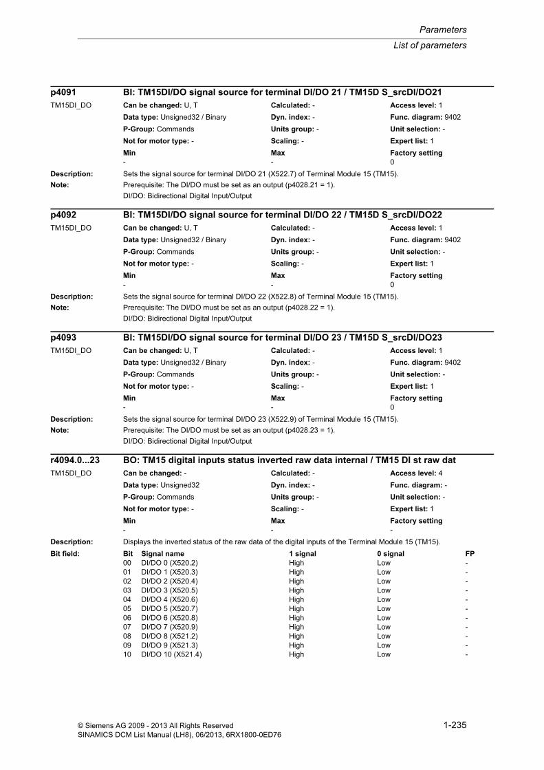
List of parameters
Parameters
1-235© Siemens AG 2009 - 2013 All Rights ReservedSINAMICS DCM List Manual (LH8), 06/2013, 6RX1800-0ED76
Description: Sets the signal source for terminal DI/DO 21 (X522.7) of Terminal Module 15 (TM15).
Note: Prerequisite: The DI/DO must be set as an output (p4028.21 = 1).
DI/DO: Bidirectional Digital Input/Output
Description: Sets the signal source for terminal DI/DO 22 (X522.8) of Terminal Module 15 (TM15).
Note: Prerequisite: The DI/DO must be set as an output (p4028.22 = 1).
DI/DO: Bidirectional Digital Input/Output
Description: Sets the signal source for terminal DI/DO 23 (X522.9) of Terminal Module 15 (TM15).
Note: Prerequisite: The DI/DO must be set as an output (p4028.23 = 1).
DI/DO: Bidirectional Digital Input/Output
Description: Displays the inverted status of the raw data of the digital inputs of the Terminal Module 15 (TM15).
p4091 BI: TM15DI/DO signal source for terminal DI/DO 21 / TM15D S_srcDI/DO21TM15DI_DO Can be changed: U, T Calculated: - Access level: 1
Data type: Unsigned32 / Binary Dyn. index: - Func. diagram: 9402
P-Group: Commands Units group: - Unit selection: -
Not for motor type: - Scaling: - Expert list: 1
Min Max Factory setting - - 0
p4092 BI: TM15DI/DO signal source for terminal DI/DO 22 / TM15D S_srcDI/DO22TM15DI_DO Can be changed: U, T Calculated: - Access level: 1
Data type: Unsigned32 / Binary Dyn. index: - Func. diagram: 9402
P-Group: Commands Units group: - Unit selection: -
Not for motor type: - Scaling: - Expert list: 1
Min Max Factory setting - - 0
p4093 BI: TM15DI/DO signal source for terminal DI/DO 23 / TM15D S_srcDI/DO23TM15DI_DO Can be changed: U, T Calculated: - Access level: 1
Data type: Unsigned32 / Binary Dyn. index: - Func. diagram: 9402
P-Group: Commands Units group: - Unit selection: -
Not for motor type: - Scaling: - Expert list: 1
Min Max Factory setting - - 0
r4094.0...23 BO: TM15 digital inputs status inverted raw data internal / TM15 DI st raw datTM15DI_DO Can be changed: - Calculated: - Access level: 4
Data type: Unsigned32 Dyn. index: - Func. diagram: -
P-Group: Commands Units group: - Unit selection: -
Not for motor type: - Scaling: - Expert list: 1
Min Max Factory setting - - -
Bit field: Bit Signal name 1 signal 0 signal FP00 DI/DO 0 (X520.2) High Low -01 DI/DO 1 (X520.3) High Low -02 DI/DO 2 (X520.4) High Low -03 DI/DO 3 (X520.5) High Low -04 DI/DO 4 (X520.6) High Low -05 DI/DO 5 (X520.7) High Low -06 DI/DO 6 (X520.8) High Low -07 DI/DO 7 (X520.9) High Low -08 DI/DO 8 (X521.2) High Low -09 DI/DO 9 (X521.3) High Low -10 DI/DO 10 (X521.4) High Low -

Parameters
List of parameters
1-236 © Siemens AG 2009 - 2013 All Rights ReservedSINAMICS DCM List Manual (LH8), 06/2013, 6RX1800-0ED76
Notice: The raw data of the digital inputs is directly displayed (e.g. without any debounce).
Note: Should only used for internal Siemens purposes (alternative r4022, r4023).
Description: Sets the simulation mode for the digital inputs of Terminal Module 15 (TM15).
Dependency: The setpoint for the input signals is specified using p4096.
Refer to: p4096
Warning: A drive that is moved by simulating the inputs of a Terminal Module is brought to a standstill while the Terminal Module is being activated or de-activated.
Note: This parameter is not saved when data is backed-up (p0971, p0977).
DI/DO: Bidirectional Digital Input/Output
11 DI/DO 11 (X521.5) High Low -12 DI/DO 12 (X521.6) High Low -13 DI/DO 13 (X521.7) High Low -14 DI/DO 14 (X521.8) High Low -15 DI/DO 15 (X521.9) High Low -16 DI/DO 16 (X522.2) High Low -17 DI/DO 17 (X522.3) High Low -18 DI/DO 18 (X522.4) High Low -19 DI/DO 19 (X522.5) High Low -20 DI/DO 20 (X522.6) High Low -21 DI/DO 21 (X522.7) High Low -22 DI/DO 22 (X522.8) High Low -23 DI/DO 23 (X522.9) High Low -
p4095 TM15DI/DO digital inputs simulation mode / TM15D DI sim_modeTM15DI_DO Can be changed: U, T Calculated: - Access level: 2
Data type: Unsigned32 Dyn. index: - Func. diagram: 9400, 9401, 9402
P-Group: Terminals Units group: - Unit selection: -
Not for motor type: - Scaling: - Expert list: 1
Min Max Factory setting - - 0000 0000 0000 0000 0000
0000 0000 0000 bin
Bit field: Bit Signal name 1 signal 0 signal FP00 DI/DO 0 (X520.2) Simulation Terminal eval -01 DI/DO 1 (X520.3) Simulation Terminal eval -02 DI/DO 2 (X520.4) Simulation Terminal eval -03 DI/DO 3 (X520.5) Simulation Terminal eval -04 DI/DO 4 (X520.6) Simulation Terminal eval -05 DI/DO 5 (X520.7) Simulation Terminal eval -06 DI/DO 6 (X520.8) Simulation Terminal eval -07 DI/DO 7 (X520.9) Simulation Terminal eval -08 DI/DO 8 (X521.2) Simulation Terminal eval -09 DI/DO 9 (X521.3) Simulation Terminal eval -10 DI/DO 10 (X521.4) Simulation Terminal eval -11 DI/DO 11 (X521.5) Simulation Terminal eval -12 DI/DO 12 (X521.6) Simulation Terminal eval -13 DI/DO 13 (X521.7) Simulation Terminal eval -14 DI/DO 14 (X521.8) Simulation Terminal eval -15 DI/DO 15 (X521.9) Simulation Terminal eval -16 DI/DO 16 (X522.2) Simulation Terminal eval -17 DI/DO 17 (X522.3) Simulation Terminal eval -18 DI/DO 18 (X522.4) Simulation Terminal eval -19 DI/DO 19 (X522.5) Simulation Terminal eval -20 DI/DO 20 (X522.6) Simulation Terminal eval -21 DI/DO 21 (X522.7) Simulation Terminal eval -22 DI/DO 22 (X522.8) Simulation Terminal eval -23 DI/DO 23 (X522.9) Simulation Terminal eval -

List of parameters
Parameters
1-237© Siemens AG 2009 - 2013 All Rights ReservedSINAMICS DCM List Manual (LH8), 06/2013, 6RX1800-0ED76
Description: Sets the simulation mode for the digital inputs of Terminal Module 31 (TM31).
Dependency: The setpoint for the input signals is specified using p4096.
Refer to: p4096
Warning: A drive that is moved by simulating the inputs of a Terminal Module is brought to a standstill while the Terminal Module is being activated or de-activated.
Note: This parameter is not saved when data is backed-up (p0971, p0977).
DI: Digital Input
DI/DO: Bidirectional Digital Input/Output
Description: Sets the setpoint for the input signals in the simulation mode of the digital inputs of Terminal Module 15 (TM15).
p4095 TM31 digital inputs simulation mode / TM31 DI sim_modeTM31 Can be changed: U, T Calculated: - Access level: 2
Data type: Unsigned32 Dyn. index: - Func. diagram: 1840, 9550, 9552, 9560, 9562
P-Group: Terminals Units group: - Unit selection: -
Not for motor type: - Scaling: - Expert list: 1
Min Max Factory setting - - 0000 0000 0000 0000 bin
Bit field: Bit Signal name 1 signal 0 signal FP00 DI 0 (X520.1) Simulation Terminal eval -01 DI 1 (X520.2) Simulation Terminal eval -02 DI 2 (X520.3) Simulation Terminal eval -03 DI 3 (X520.4) Simulation Terminal eval -04 DI 4 (X530.1) Simulation Terminal eval -05 DI 5 (X530.2) Simulation Terminal eval -06 DI 6 (X530.3) Simulation Terminal eval -07 DI 7 (X530.4) Simulation Terminal eval -08 DI/DO 8 (X541.2) Simulation Terminal eval -09 DI/DO 9 (X541.3) Simulation Terminal eval -10 DI/DO 10 (X541.4) Simulation Terminal eval -11 DI/DO 11 (X541.5) Simulation Terminal eval -
p4096 TM15DI/DO digital inputs simulation mode, setpoint / TM15D DI sim setpTM15DI_DO Can be changed: U, T Calculated: - Access level: 2
Data type: Unsigned32 Dyn. index: - Func. diagram: 9400, 9401, 9402
P-Group: Terminals Units group: - Unit selection: -
Not for motor type: - Scaling: - Expert list: 1
Min Max Factory setting - - 0000 0000 0000 0000 0000
0000 0000 0000 bin
Bit field: Bit Signal name 1 signal 0 signal FP00 DI/DO 0 (X520.2) High Low -01 DI/DO 1 (X520.3) High Low -02 DI/DO 2 (X520.4) High Low -03 DI/DO 3 (X520.5) High Low -04 DI/DO 4 (X520.6) High Low -05 DI/DO 5 (X520.7) High Low -06 DI/DO 6 (X520.8) High Low -07 DI/DO 7 (X520.9) High Low -08 DI/DO 8 (X521.2) High Low -09 DI/DO 9 (X521.3) High Low -10 DI/DO 10 (X521.4) High Low -11 DI/DO 11 (X521.5) High Low -12 DI/DO 12 (X521.6) High Low -13 DI/DO 13 (X521.7) High Low -

Parameters
List of parameters
1-238 © Siemens AG 2009 - 2013 All Rights ReservedSINAMICS DCM List Manual (LH8), 06/2013, 6RX1800-0ED76
Dependency: The simulation of a digital input is selected using p4095.
Refer to: p4095
Note: This parameter is not saved when data is backed-up (p0971, p0977).
DI/DO: Bidirectional Digital Input/Output
Description: Sets the setpoint for the input signals in the simulation mode of the digital inputs of Terminal Module 31 (TM31).
Dependency: The simulation of a digital input is selected using p4095.
Refer to: p4095
Note: This parameter is not saved when data is backed-up (p0971, p0977).
DI: Digital Input
DI/DO: Bidirectional Digital Input/Output
Description: Sets the simulation mode for the analog inputs of Terminal Module 31 (TM31).
Value: 0: Terminal evaluation for analog input x1: Simulation for analog input x
Index: [0] = AI 0 (X521.1/X521.2, S5.0)[1] = AI 1 (X521.3/X521.4, S5.1)
14 DI/DO 14 (X521.8) High Low -15 DI/DO 15 (X521.9) High Low -16 DI/DO 16 (X522.2) High Low -17 DI/DO 17 (X522.3) High Low -18 DI/DO 18 (X522.4) High Low -19 DI/DO 19 (X522.5) High Low -20 DI/DO 20 (X522.6) High Low -21 DI/DO 21 (X522.7) High Low -22 DI/DO 22 (X522.8) High Low -23 DI/DO 23 (X522.9) High Low -
p4096 TM31 digital inputs simulation mode setpoint / TM31 DI sim setpTM31 Can be changed: U, T Calculated: - Access level: 2
Data type: Unsigned32 Dyn. index: - Func. diagram: 1840, 9550, 9552, 9560, 9562
P-Group: Terminals Units group: - Unit selection: -
Not for motor type: - Scaling: - Expert list: 1
Min Max Factory setting - - 0000 0000 0000 0000 bin
Bit field: Bit Signal name 1 signal 0 signal FP00 DI 0 (X520.1) High Low -01 DI 1 (X520.2) High Low -02 DI 2 (X520.3) High Low -03 DI 3 (X520.4) High Low -04 DI 4 (X530.1) High Low -05 DI 5 (X530.2) High Low -06 DI 6 (X530.3) High Low -07 DI 7 (X530.4) High Low -08 DI/DO 8 (X541.2) High Low -09 DI/DO 9 (X541.3) High Low -10 DI/DO 10 (X541.4) High Low -11 DI/DO 11 (X541.5) High Low -
p4097[0...1] TM31 analog inputs simulation mode / TM31 AI sim_modeTM31 Can be changed: U, T Calculated: - Access level: 2
Data type: Integer16 Dyn. index: - Func. diagram: 9566, 9568
P-Group: Terminals Units group: - Unit selection: -
Not for motor type: - Scaling: - Expert list: 1
Min Max Factory setting 0 1 0

List of parameters
Parameters
1-239© Siemens AG 2009 - 2013 All Rights ReservedSINAMICS DCM List Manual (LH8), 06/2013, 6RX1800-0ED76
Dependency: The setpoint for the input voltage is specified via p4098.
Refer to: p4098
Note: This parameter is not saved when data is backed-up (p0971, p0977).
AI: Analog Input
Description: Sets the setpoint for the input value in simulation mode of the analog inputs of Terminal Module 31 (TM31).
Index: [0] = AI 0 (X521.1/X521.2, S5.0)[1] = AI 1 (X521.3/X521.4, S5.1)
Dependency: The simulation of an analog input is selected using p4097.
If AI x is parameterized as voltage input (p4056), then the setpoint is a voltage in V.
If AI x is parameterized as current input (p4056), then the setpoint is a current in mA.
Refer to: p4056, p4097
Note: This parameter is not saved when data is backed-up (p0971, p0977).
AI: Analog Input
Description: Sets the sampling time for the inputs and outputs of Terminal Module 15 (TM15).
Dependency: The parameter can only be modified for p0009 = 3, 29.
The following applies for the sampling time:
The sampling times at a DRIVE-CLiQ line must be integral multiples of one another.
The sampling times of this TM must be an integral multiple of a servo or vector drive that exists in the system.
The minimum permissible sampling time is 125 µs.
Refer to: p0009, r0110, r0111
Note: The changed sampling time is immediately effective after a completed sub-boot (p0009 -> 0).
Parameter p4099[0] must never be equal to zero.
Description: Sets the sampling time for the inputs and outputs of Terminal Module 31 (TM31).
Index: [0] = Digital inputs/outputs (DI/DO)[1] = Analog inputs (AI)[2] = Analog outputs (AO)
p4098[0...1] TM31 analog inputs simulation mode setpoint / TM31 AI sim setpTM31 Can be changed: U, T Calculated: - Access level: 2
Data type: FloatingPoint32 Dyn. index: - Func. diagram: 9566, 9568
P-Group: Terminals Units group: - Unit selection: -
Not for motor type: - Scaling: - Expert list: 1
Min Max Factory setting -20.000 20.000 0.000
p4099 TM15DI/DO inputs/outputs sampling time / TM15D I/O t_samplTM15DI_DO Can be changed: C1(3) Calculated: - Access level: 3
Data type: FloatingPoint32 Dyn. index: - Func. diagram: 1781, 9400
P-Group: Commands Units group: - Unit selection: -
Not for motor type: - Scaling: - Expert list: 1
Min Max Factory setting 0.00 [µs] 5000.00 [µs] 4000.00 [µs]
p4099[0...2] TM31 inputs/outputs sampling time / TM31 I/O t_sampleTM31 Can be changed: C1(3) Calculated: - Access level: 3
Data type: FloatingPoint32 Dyn. index: - Func. diagram: 1840, 9550
P-Group: Commands Units group: - Unit selection: -
Not for motor type: - Scaling: - Expert list: 1
Min Max Factory setting 0.00 [µs] 5000.00 [µs] 4000.00 [µs]
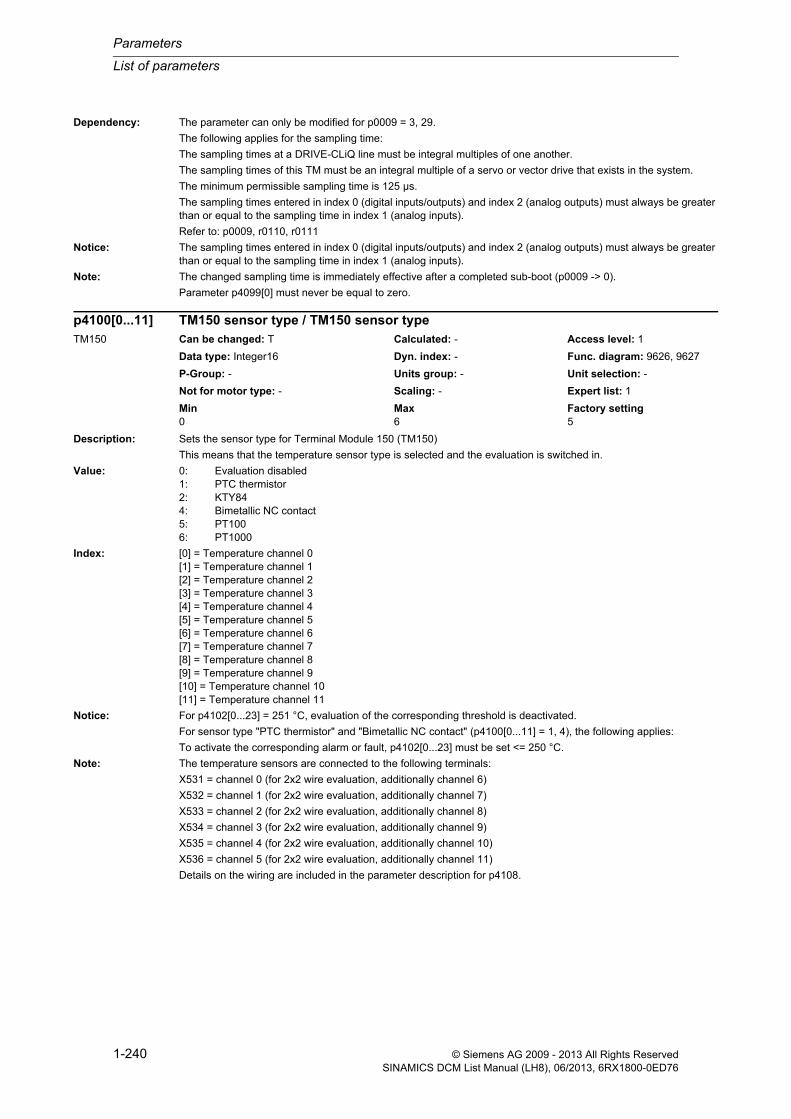
Parameters
List of parameters
1-240 © Siemens AG 2009 - 2013 All Rights ReservedSINAMICS DCM List Manual (LH8), 06/2013, 6RX1800-0ED76
Dependency: The parameter can only be modified for p0009 = 3, 29.
The following applies for the sampling time:
The sampling times at a DRIVE-CLiQ line must be integral multiples of one another.
The sampling times of this TM must be an integral multiple of a servo or vector drive that exists in the system.
The minimum permissible sampling time is 125 µs.
The sampling times entered in index 0 (digital inputs/outputs) and index 2 (analog outputs) must always be greater than or equal to the sampling time in index 1 (analog inputs).
Refer to: p0009, r0110, r0111
Notice: The sampling times entered in index 0 (digital inputs/outputs) and index 2 (analog outputs) must always be greater than or equal to the sampling time in index 1 (analog inputs).
Note: The changed sampling time is immediately effective after a completed sub-boot (p0009 -> 0).
Parameter p4099[0] must never be equal to zero.
Description: Sets the sensor type for Terminal Module 150 (TM150)
This means that the temperature sensor type is selected and the evaluation is switched in.
Value: 0: Evaluation disabled1: PTC thermistor2: KTY844: Bimetallic NC contact5: PT1006: PT1000
Index: [0] = Temperature channel 0[1] = Temperature channel 1[2] = Temperature channel 2[3] = Temperature channel 3[4] = Temperature channel 4[5] = Temperature channel 5[6] = Temperature channel 6[7] = Temperature channel 7[8] = Temperature channel 8[9] = Temperature channel 9[10] = Temperature channel 10[11] = Temperature channel 11
Notice: For p4102[0...23] = 251 °C, evaluation of the corresponding threshold is deactivated.
For sensor type "PTC thermistor" and "Bimetallic NC contact" (p4100[0...11] = 1, 4), the following applies:
To activate the corresponding alarm or fault, p4102[0...23] must be set <= 250 °C.
Note: The temperature sensors are connected to the following terminals:
X531 = channel 0 (for 2x2 wire evaluation, additionally channel 6)
X532 = channel 1 (for 2x2 wire evaluation, additionally channel 7)
X533 = channel 2 (for 2x2 wire evaluation, additionally channel 8)
X534 = channel 3 (for 2x2 wire evaluation, additionally channel 9)
X535 = channel 4 (for 2x2 wire evaluation, additionally channel 10)
X536 = channel 5 (for 2x2 wire evaluation, additionally channel 11)
Details on the wiring are included in the parameter description for p4108.
p4100[0...11] TM150 sensor type / TM150 sensor typeTM150 Can be changed: T Calculated: - Access level: 1
Data type: Integer16 Dyn. index: - Func. diagram: 9626, 9627
P-Group: - Units group: - Unit selection: -
Not for motor type: - Scaling: - Expert list: 1
Min Max Factory setting 0 6 5

List of parameters
Parameters
1-241© Siemens AG 2009 - 2013 All Rights ReservedSINAMICS DCM List Manual (LH8), 06/2013, 6RX1800-0ED76
Description: Sets the sensor type for Terminal Module 31 (TM31)
This means that the temperature sensor type is selected and the evaluation is switched in.
Value: 0: Evaluation disabled1: PTC thermistor2: KTY84
Notice: For p4102[0...1] = 251 °C, evaluation of the corresponding threshold is deactivated.
For sensor type "PTC thermistor" (p4100 = 1), the following applies:
To activate the corresponding alarm or fault, p4102[0...1] must be set <= 250 °C.
Note: The temperature sensor is connected at terminals X522.7(+) and X522.8(-).
Description: Displays the actual resistance value of the temperature sensor connected at the Terminal Module.
Index: [0] = Temperature channel 0[1] = Temperature channel 1[2] = Temperature channel 2[3] = Temperature channel 3[4] = Temperature channel 4[5] = Temperature channel 5[6] = Temperature channel 6[7] = Temperature channel 7[8] = Temperature channel 8[9] = Temperature channel 9[10] = Temperature channel 10[11] = Temperature channel 11
Note: The maximum measurable resistance value is approx. 2500 Ohm.
For 1x2 and 2x2 wire evaluation:
The actual sensor resistance is displayed in this parameter(i.e. the wire resistance (p4110) is taken into account).
The temperature sensors are connected to the following terminals:
X531 = channel 0 (for 2x2 wire evaluation, additionally channel 6)
X532 = channel 1 (for 2x2 wire evaluation, additionally channel 7)
X533 = channel 2 (for 2x2 wire evaluation, additionally channel 8)
X534 = channel 3 (for 2x2 wire evaluation, additionally channel 9)
X535 = channel 4 (for 2x2 wire evaluation, additionally channel 10)
X536 = channel 5 (for 2x2 wire evaluation, additionally channel 11)
Details on the wiring are included in the parameter description for p4108.
p4100 TM31 sensor type / TM31 sensor typeTM31 Can be changed: T Calculated: - Access level: 1
Data type: Integer16 Dyn. index: - Func. diagram: 9576
P-Group: - Units group: - Unit selection: -
Not for motor type: - Scaling: - Expert list: 1
Min Max Factory setting 0 2 0
r4101[0...11] TM150 sensor resistance / TM150 R_sensorTM150 Can be changed: - Calculated: - Access level: 3
Data type: FloatingPoint32 Dyn. index: - Func. diagram: 9626, 9627
P-Group: Terminals Units group: - Unit selection: -
Not for motor type: - Scaling: PERCENT Expert list: 1
Min Max Factory setting - [ohm] - [ohm] - [ohm]

Parameters
List of parameters
1-242 © Siemens AG 2009 - 2013 All Rights ReservedSINAMICS DCM List Manual (LH8), 06/2013, 6RX1800-0ED76
Description: Displays the actual resistance value of the temperature sensor connected at the Terminal Module.
Note: The maximum measurable resistance value is approx. 2170 Ohm.
The temperature sensor is connected at terminals X522.7(+) and X522.8(-).
Description: Sets the fault threshold/alarm threshold for Terminal Module 150 (TM150).
For alarms (even indices [0, 2, 4 ... 22]), the following applies:
- The corresponding alarm is initiated, if the temperature actual value associated with a temperature channel exceeds the associated alarm threshold (r4105[x] > p4102[2x]. In addition, the timer is started (p4103[x]).
- The alarm remains until the temperature actual value (r4105[x]) reaches or falls below the threshold value (p4102[2x] - hysteresis (p4118[x]).
For faults (uneven indices [1, 3, 5 ... 23]), the following applies:
- The corresponding fault is initiated, if the temperature actual value associated with a temperature channel exceeds the associated fault threshold (r4105[x] > p4102[2x+1] or the associated timer (p4103[x] has expired.
- The fault remains until the temperature actual value (r4105[x]) reaches or falls below the threshold value (p4102[2x+1]) - hysteresis (p4118[x]) and the fault has been acknowledged.
Index: [0] = Channel 0 alarm threshold (A35211)[1] = Channel 0 fault threshold (F35207)[2] = Channel 1 alarm threshold (A35212)[3] = Channel 1 fault threshold (F35208)[4] = Channel 2 alarm threshold (A35213)[5] = Channel 2 fault threshold (F35209)[6] = Channel 3 alarm threshold (A35214)[7] = Channel 3 fault threshold (F35210)[8] = Channel 4 alarm threshold (A35410)[9] = Channel 4 fault threshold (F35400)[10] = Channel 5 alarm threshold (A35411)[11] = Channel 5 fault threshold (F35401)[12] = Channel 6 alarm threshold (A35412)[13] = Channel 6 fault threshold (F35402)[14] = Channel 7 alarm threshold (A35413)[15] = Channel 7 fault threshold (F35403)[16] = Channel 8 alarm threshold (A35414)[17] = Channel 8 fault threshold (F35404)[18] = Channel 9 alarm threshold (A35415)[19] = Channel 9 fault threshold (F35405)[20] = Channel 10 alarm threshold (A35416)[21] = Channel 10 fault threshold (F35406)[22] = Channel 11 alarm threshold (A35417)[23] = Channel 11 fault threshold (F35407)
Dependency: Refer to: p4103, r4104, r4105, p4118
r4101 TM31 sensor resistance / TM31 R_sensorTM31 Can be changed: - Calculated: - Access level: 3
Data type: Unsigned16 Dyn. index: - Func. diagram: 9576
P-Group: Terminals Units group: - Unit selection: -
Not for motor type: - Scaling: PERCENT Expert list: 1
Min Max Factory setting - [ohm] - [ohm] - [ohm]
p4102[0...23] TM150 fault threshold/alarm threshold / TM150 F/A_threshTM150 Can be changed: T Calculated: - Access level: 1
Data type: Integer16 Dyn. index: - Func. diagram: 9626, 9627
P-Group: - Units group: - Unit selection: -
Not for motor type: - Scaling: - Expert list: 1
Min Max Factory setting -99 [°C] 251 [°C] 251 [°C]
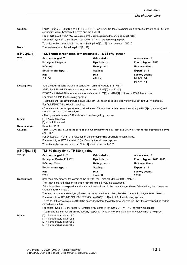
List of parameters
Parameters
1-243© Siemens AG 2009 - 2013 All Rights ReservedSINAMICS DCM List Manual (LH8), 06/2013, 6RX1800-0ED76
Caution: Faults F35207 ... F35210 and F35400 ... F35407 only result in the drive being shut down if at least one BICO inter-connection exists between the drive and the TM150.
For p4102[0...23] = 251 °C, evaluation of the corresponding threshold is deactivated.
For sensor type "PTC thermistor" (p4100[0...11] = 1), the following applies:
To activate the corresponding alarm or fault, p4102[0...23] must be set <= 250 °C.
Note: The hysteresis can be set in p4118[0...11].
Description: Sets the fault threshold/alarm threshold for Terminal Module 31 (TM31).
A35211 is initiated, if the temperature actual value r4105[0] > p4102[0]
F35207 is initiated if the temperature actual value r4105[0] > p4102[1] or timer p4103[0] has expired
For alarm A35211 the following applies:
- Remains until the temperature actual value (r4105) reaches or falls below the value (p4102[0] - hysteresis).
For fault F35207 the following applies:
- Remains until the temperature actual value (r4105) reaches or falls below the value (p4102[1] - hysteresis) and the fault has been acknowledged.
- The hysteresis value is 5 K and cannot be changed by the user.
Index: [0] = Alarm threshold[1] = Fault threshold
Dependency: Refer to: r4104
Caution: Fault F35207 only causes the drive to be shut down if there is at least one BICO interconnection between the drive and TM31.
For p4102[0...1] = 251 °C, evaluation of the corresponding threshold is deactivated.
For sensor type "PTC thermistor" (p4100 = 1), the following applies:
To activate the alarm or fault, p4102[0...1] must be set <= 250 °C.
Description: Sets the delay time for the output of the fault for the Terminal Module 150 (TM150).
The timer is started when the alarm threshold (e.g. p4102[0]) is exceeded.
If the delay time has expired and the alarm threshold has, in the meantime, not been fallen below, then the corre-sponding fault is output.
The fault can be acknowledged, if, after the delay time has expired, the alarm threshold is again fallen below.
For sensor type "KTY84", "PT100", "PT1000" (p4100[0...11] = 2, 5, 6) the following applies:
- If the fault threshold (e.g. p4102[1]) is exceeded before the delay time has expired, then the corresponding fault is immediately output.
For sensor type "PTC thermistor", "Bimetallic NC contact" (p4100[0...11] = 1, 4), the following applies:
- Alarm and fault threshold simultaneously respond. The fault is only issued after the delay time has expired.
Index: [0] = Temperature channel 0[1] = Temperature channel 1[2] = Temperature channel 2[3] = Temperature channel 3
p4102[0...1] TM31 fault threshold/alarm threshold / TM31 F/A_threshTM31 Can be changed: T Calculated: - Access level: 1
Data type: Integer16 Dyn. index: - Func. diagram: 9576
P-Group: - Units group: - Unit selection: -
Not for motor type: - Scaling: - Expert list: 1
Min Max Factory setting -48 [°C] 251 [°C] [0] 100 [°C]
[1] 120 [°C]
p4103[0...11] TM150 delay time / TM150 t_delayTM150 Can be changed: U, T Calculated: - Access level: 1
Data type: FloatingPoint32 Dyn. index: - Func. diagram: 9626, 9627
P-Group: Motor Units group: - Unit selection: -
Not for motor type: - Scaling: - Expert list: 1
Min Max Factory setting 0.0 [s] 600.0 [s] 0.0 [s]

Parameters
List of parameters
1-244 © Siemens AG 2009 - 2013 All Rights ReservedSINAMICS DCM List Manual (LH8), 06/2013, 6RX1800-0ED76
[4] = Temperature channel 4[5] = Temperature channel 5[6] = Temperature channel 6[7] = Temperature channel 7[8] = Temperature channel 8[9] = Temperature channel 9[10] = Temperature channel 10[11] = Temperature channel 11
Dependency: Refer to: p4102, r4104, r4105, p4118
Warning: The fault F35207 ... F35210 and F35400 ... 35407 only results in the drive being shut down if at least one BICO interconnection exists between the drive and the TM150.
Note: For p4103 = 0 s and sensor type "KTY84", "PT100", "PT1000" (p4100[0...11] = 2, 5, 6) the following applies:
- The corresponding fault can only be initiated via the fault threshold (output of the timer is always a logical 0).
For p4103 = 0 s and sensor type "PTC thermistor", "Bimetallic NC contact" (p4100[0...11] = 1, 4), the following applies:
- The corresponding alarm and fault are simultaneously output (delay time = 0 s).
Description: Sets the delay time for the output of the fault for the Terminal Module 31 (TM31).
The timer is started when the alarm threshold (p4102[0]) is exceeded.
If the delay time has expired and the alarm threshold has, in the meantime, not been fallen below, then fault F35207 is output.
The fault can be acknowledged, if, after the delay time has expired, the alarm threshold is again fallen below.
For sensor type "KTY84" (p4100 = 2), the following applies:
If the fault threshold (p4102[1]) is exceeded before the delay time has expired, then fault F35207 is immediately output.
For sensor type "PTC thermistor" (p4100 = 1), the following applies:
- Alarm and fault threshold simultaneously respond. The fault is only issued after the delay time has expired.
Dependency: Refer to: r4104
Warning: Fault F35207 only causes the drive to be shut down if there is at least one BICO interconnection between the drive and TM31.
Note: With p4103 = 0 ms, the timer is de-activated and only the fault threshold is effective.
Description: Display and binector output for the status for the Terminal Module 150 (TM150).
p4103 TM31 temperature evaluation delay time / TM31 temp t_delayTM31 Can be changed: U, T Calculated: - Access level: 1
Data type: FloatingPoint32 Dyn. index: - Func. diagram: 9576
P-Group: Motor Units group: - Unit selection: -
Not for motor type: - Scaling: - Expert list: 1
Min Max Factory setting 0.000 [ms] 600000.000 [ms] 0.000 [ms]
r4104.0...23 BO: TM150 temperature evaluation status / TM150 temp statusTM150 Can be changed: - Calculated: - Access level: 1
Data type: Unsigned32 Dyn. index: - Func. diagram: 9626, 9627
P-Group: Terminals Units group: - Unit selection: -
Not for motor type: - Scaling: - Expert list: 1
Min Max Factory setting - - -
Bit field: Bit Signal name 1 signal 0 signal FP00 Channel 0 alarm present Yes No 962601 Channel 0 fault present Yes No 962602 Channel 1 alarm present Yes No 962603 Channel 1 fault present Yes No 9626

List of parameters
Parameters
1-245© Siemens AG 2009 - 2013 All Rights ReservedSINAMICS DCM List Manual (LH8), 06/2013, 6RX1800-0ED76
Dependency: Refer to: p4102, p4103, r4105, p4118
Description: Display and binector output for the status for the Terminal Module 31 (TM31).
Dependency: Refer to: p4102
Description: Displays the temperature actual value for the Terminal Module 150 (TM150)
Index: [0] = Temperature channel 0[1] = Temperature channel 1[2] = Temperature channel 2[3] = Temperature channel 3[4] = Temperature channel 4[5] = Temperature channel 5[6] = Temperature channel 6[7] = Temperature channel 7[8] = Temperature channel 8[9] = Temperature channel 9[10] = Temperature channel 10[11] = Temperature channel 11
04 Channel 2 alarm present Yes No 962605 Channel 2 fault present Yes No 962606 Channel 3 alarm present Yes No 962607 Channel 3 fault present Yes No 962608 Channel 4 alarm present Yes No 962609 Channel 4 fault present Yes No 962610 Channel 5 alarm present Yes No 962611 Channel 5 fault present Yes No 962612 Channel 6 alarm present Yes No 962713 Channel 6 fault present Yes No 962714 Channel 7 alarm present Yes No 962715 Channel 7 fault present Yes No 962716 Channel 8 alarm present Yes No 962717 Channel 8 fault present Yes No 962718 Channel 9 alarm present Yes No 962719 Channel 9 fault present Yes No 962720 Channel 10 alarm present Yes No 962721 Channel 10 fault present Yes No 962722 Channel 11 alarm present Yes No 962723 Channel 11 fault present Yes No 9627
r4104.0...1 BO: TM31 temperature evaluation status / TM31 temp statusTM31 Can be changed: - Calculated: - Access level: 1
Data type: Unsigned16 Dyn. index: - Func. diagram: 1840, 9576
P-Group: Terminals Units group: - Unit selection: -
Not for motor type: - Scaling: - Expert list: 1
Min Max Factory setting - - -
Bit field: Bit Signal name 1 signal 0 signal FP00 Alarm is present Yes No -01 Fault is present Yes No -
r4105[0...11] CO: TM150 temperature actual value / TM150 temp_act valTM150 Can be changed: - Calculated: - Access level: 1
Data type: FloatingPoint32 Dyn. index: - Func. diagram: 9626, 9627
P-Group: Terminals Units group: - Unit selection: -
Not for motor type: - Scaling: p2006 Expert list: 1
Min Max Factory setting - [°C] - [°C] - [°C]

Parameters
List of parameters
1-246 © Siemens AG 2009 - 2013 All Rights ReservedSINAMICS DCM List Manual (LH8), 06/2013, 6RX1800-0ED76
Dependency: For sensor type "PTC thermistor" and "Bimetallic NC contact" (p4100[0...11] = 1, 4), the following applies:
- below the nominal response temperature, r4105[0...11] = -50 °C.
- above the nominal response temperature, r4105[0...11] = 250 °C.
For sensor type "KTY84", "PT100", "PT1000" (p4100[0...11] = 2, 5, 6) the following applies:
- the displayed value corresponds to the temperature actual value.
Refer to: p4100, p4111, r4112, r4113, r4114
Note: r4105[0...11] = -300 °C is displayed in the following cases:
- temperature actual value invalid (F35920 ... F35931 output).
- no sensor selected (p4100[0...11] = 0).
The temperature actual values can be grouped using p4111[0...2] and the maximum value, minimum value as well as the average value for each group evaluated (r4112[0...2], r4113[0...2], r4114[0...2]).
Description: Displays the temperature actual value for the Terminal Module 31 (TM31)
Dependency: For sensor type "PTC thermistor" (p4100 = 1), the following applies:
- below the nominal response temperature, r4105 = -50°C.
- above the nominal response temperature, r4105 = 250 °C.
For sensor type "KTY84" (p4100 = 2), the following applies:
- the displayed value corresponds to the temperature actual value.
Refer to: p4100
Note: r4105 = -300 °C is displayed in the following cases:
- temperature actual value invalid (F35920 output).
- no sensor selected (p4100 = 0).
The temperature sensor is connected at terminals X522.7(+) and X522.8(-).
Description: Sets the measuring method for the terminal block X531 ... X536 for the Terminal Module 150 (TM150).
Re p4108[0...5] = 0 (1x2 wire evaluation):
- the temperature sensor is connected at terminals 1(+) and 2(-).
Re p4108[0...5] = 1 (2x2 wire evaluation):
- The first temperature sensor is connected at terminals 1(+) and 2(-).
- The second temperature sensor is connected at terminals 3(+) and 4(-).
Re p4108[0...5] = 2 (3 wire evaluation):
- the temperature sensor is connected at terminals 3(+) and 4(-).
- the measuring conductor is connected at terminal 1(+).
- terminals 2(-) and 4(-) must be jumpered.
Re p4108[0...5] = 3 (4 wire evaluation):
- the temperature sensor is connected at terminals 3(+) and 4(-).
- the measuring conductor is connected at terminals 1(+) and 2(-).
r4105 CO: TM31 temperature actual value / TM31 temp_act valTM31 Can be changed: - Calculated: - Access level: 1
Data type: FloatingPoint32 Dyn. index: - Func. diagram: 1840, 9576
P-Group: Terminals Units group: - Unit selection: -
Not for motor type: - Scaling: p2006 Expert list: 1
Min Max Factory setting - [°C] - [°C] - [°C]
p4108[0...5] TM150 terminal block measuring method / TM150 meas methodTM150 Can be changed: T Calculated: - Access level: 1
Data type: Integer16 Dyn. index: - Func. diagram: 9625, 9626, 9627
P-Group: - Units group: - Unit selection: -
Not for motor type: - Scaling: - Expert list: 1
Min Max Factory setting 0 3 1
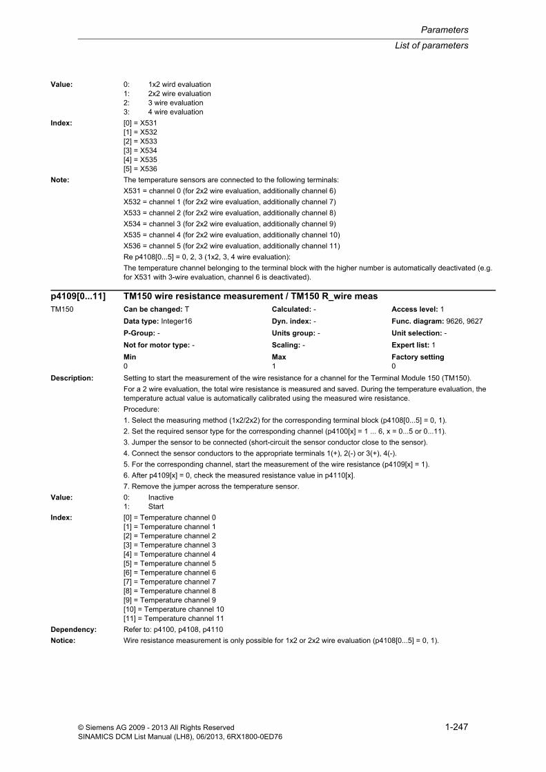
List of parameters
Parameters
1-247© Siemens AG 2009 - 2013 All Rights ReservedSINAMICS DCM List Manual (LH8), 06/2013, 6RX1800-0ED76
Value: 0: 1x2 wird evaluation1: 2x2 wire evaluation2: 3 wire evaluation3: 4 wire evaluation
Index: [0] = X531[1] = X532[2] = X533[3] = X534[4] = X535[5] = X536
Note: The temperature sensors are connected to the following terminals:
X531 = channel 0 (for 2x2 wire evaluation, additionally channel 6)
X532 = channel 1 (for 2x2 wire evaluation, additionally channel 7)
X533 = channel 2 (for 2x2 wire evaluation, additionally channel 8)
X534 = channel 3 (for 2x2 wire evaluation, additionally channel 9)
X535 = channel 4 (for 2x2 wire evaluation, additionally channel 10)
X536 = channel 5 (for 2x2 wire evaluation, additionally channel 11)
Re p4108[0...5] = 0, 2, 3 (1x2, 3, 4 wire evaluation):
The temperature channel belonging to the terminal block with the higher number is automatically deactivated (e.g. for X531 with 3-wire evaluation, channel 6 is deactivated).
Description: Setting to start the measurement of the wire resistance for a channel for the Terminal Module 150 (TM150).
For a 2 wire evaluation, the total wire resistance is measured and saved. During the temperature evaluation, the temperature actual value is automatically calibrated using the measured wire resistance.
Procedure:
1. Select the measuring method (1x2/2x2) for the corresponding terminal block (p4108[0...5] = 0, 1).
2. Set the required sensor type for the corresponding channel (p4100[x] = 1 ... 6, x = 0...5 or 0...11).
3. Jumper the sensor to be connected (short-circuit the sensor conductor close to the sensor).
4. Connect the sensor conductors to the appropriate terminals 1(+), 2(-) or 3(+), 4(-).
5. For the corresponding channel, start the measurement of the wire resistance (p4109[x] = 1).
6. After p4109[x] = 0, check the measured resistance value in p4110[x].
7. Remove the jumper across the temperature sensor.
Value: 0: Inactive1: Start
Index: [0] = Temperature channel 0[1] = Temperature channel 1[2] = Temperature channel 2[3] = Temperature channel 3[4] = Temperature channel 4[5] = Temperature channel 5[6] = Temperature channel 6[7] = Temperature channel 7[8] = Temperature channel 8[9] = Temperature channel 9[10] = Temperature channel 10[11] = Temperature channel 11
Dependency: Refer to: p4100, p4108, p4110
Notice: Wire resistance measurement is only possible for 1x2 or 2x2 wire evaluation (p4108[0...5] = 0, 1).
p4109[0...11] TM150 wire resistance measurement / TM150 R_wire measTM150 Can be changed: T Calculated: - Access level: 1
Data type: Integer16 Dyn. index: - Func. diagram: 9626, 9627
P-Group: - Units group: - Unit selection: -
Not for motor type: - Scaling: - Expert list: 1
Min Max Factory setting 0 1 0

Parameters
List of parameters
1-248 © Siemens AG 2009 - 2013 All Rights ReservedSINAMICS DCM List Manual (LH8), 06/2013, 6RX1800-0ED76
Note: The wire resistance value can be also directly entered into p4110[0...11].
The automatic conductor calibration for 1x2 and 2x2 wire evaluation is always performed with the value in p4110[0...11].
Description: Sets and displays the wire resistance for Terminal Module 150 (TM150).
The value is used for the automatic conductor calibration.
The value is automatically set by starting the wire resistance measurement (p4109[0...11]) of the corresponding channel.
Index: [0] = Temperature channel 0[1] = Temperature channel 1[2] = Temperature channel 2[3] = Temperature channel 3[4] = Temperature channel 4[5] = Temperature channel 5[6] = Temperature channel 6[7] = Temperature channel 7[8] = Temperature channel 8[9] = Temperature channel 9[10] = Temperature channel 10[11] = Temperature channel 11
Dependency: Refer to: p4109
Notice: Wire resistance measurement is only possible for 1x2 or 2x2 wire evaluation (p4108[0...5] = 0, 1).
Note: Automatic conductor calibration is deactivated using p4110[0...11] = 0.
Description: Assigns the temperature channels to groups for the Terminal Module 150 (TM150)
For each group, the following calculated values are provided from the temperature actual values (r4105[0...11]):
- Maximum value (r4112[0...2])
- Minimum value (r4113[0...2])
- average value (r4114[0...2])
Index: [0] = Group 0[1] = Group 1[2] = Group 2
p4110[0...11] TM150 wire resistance value / TM150 R_wire valueTM150 Can be changed: T Calculated: - Access level: 1
Data type: FloatingPoint32 Dyn. index: - Func. diagram: 9626, 9627
P-Group: - Units group: - Unit selection: -
Not for motor type: - Scaling: - Expert list: 1
Min Max Factory setting 0.00 [ohm] 3000.00 [ohm] 0.00 [ohm]
p4111[0...2] TM150 group channel assignment / TM150 grp channelTM150 Can be changed: T Calculated: - Access level: 1
Data type: Unsigned16 Dyn. index: - Func. diagram: 9625
P-Group: - Units group: - Unit selection: -
Not for motor type: - Scaling: - Expert list: 1
Min Max Factory setting - - 0000 0000 0000 0000 bin
Bit field: Bit Signal name 1 signal 0 signal FP00 Temperature channel 0 Yes No -01 Temperature channel 1 Yes No -02 Temperature channel 2 Yes No -03 Temperature channel 3 Yes No -04 Temperature channel 4 Yes No -05 Temperature channel 5 Yes No -06 Temperature channel 6 Yes No -07 Temperature channel 7 Yes No -08 Temperature channel 8 Yes No -09 Temperature channel 9 Yes No -

List of parameters
Parameters
1-249© Siemens AG 2009 - 2013 All Rights ReservedSINAMICS DCM List Manual (LH8), 06/2013, 6RX1800-0ED76
Dependency: Refer to: r4105, r4112, r4113, r4114
Caution: When forming groups, it must be ensured that in one particular group, only temperature channels with the following sensor types are included:
- "KTY84", "PT100", "PT1000" (p4100[0...11] = 2, 5, 6), real temperature actual value
or alternatively
- "PTC thermistor", "bimetallic NC contact" (p4100[0...11] = 1, 4), fictitious temperature actual value (-50 °C, 250 °C)
If these sensor types are combined within one group, then the calculated values for maximum, minimum and aver-age value will be falsified.
Note: Active and inactive temperature channels can be included in one group. However, when calculating the values (r4112, r4113, r4114) only the active temperature channels with valid actual value are taken into account (r4105[0...11] not equal to -300 °C).
Description: Display and connector output for the maximum value of each group for the Terminal Module 150 (TM150).
This value is calculated from the actual temperature values (r4105[0...11]) of each group.
Recommend.: The following connector inputs can use these connector outputs for interconnection:
- CI: p0603
- CI: p0608[0...3]
- CI: p0609[0...3]
- CI: p2051
Index: [0] = Group 0[1] = Group 1[2] = Group 2
Dependency: Refer to: r4105, p4111, r4113, r4114
Description: Display and connector output for the minimum value of each group for the Terminal Module 150 (TM150).
This value is calculated from the actual temperature values (r4105[0...11]) of each group.
Recommend.: The following connector inputs can use these connector outputs for interconnection:
- CI: p0603
- CI: p0608[0...3]
- CI: p0609[0...3]
- CI: p2051
Index: [0] = Group 0[1] = Group 1[2] = Group 2
Dependency: Refer to: r4105, p4111, r4112, r4114
10 Temperature channel 10 Yes No -11 Temperature channel 11 Yes No -
r4112[0...2] CO: TM150 group temperature actual value maximum value / TM150 grp temp maxTM150 Can be changed: - Calculated: - Access level: 1
Data type: FloatingPoint32 Dyn. index: - Func. diagram: 9625
P-Group: - Units group: - Unit selection: -
Not for motor type: - Scaling: - Expert list: 1
Min Max Factory setting - [°C] - [°C] - [°C]
r4113[0...2] CO: TM150 group temperature actual value minimum value / TM150 grp temp minTM150 Can be changed: - Calculated: - Access level: 1
Data type: FloatingPoint32 Dyn. index: - Func. diagram: 9625
P-Group: - Units group: - Unit selection: -
Not for motor type: - Scaling: - Expert list: 1
Min Max Factory setting - [°C] - [°C] - [°C]

Parameters
List of parameters
1-250 © Siemens AG 2009 - 2013 All Rights ReservedSINAMICS DCM List Manual (LH8), 06/2013, 6RX1800-0ED76
Description: Display and connector output for the average value of each group for the Terminal Module 150 (TM150).
This value is calculated from the actual temperature values (r4105[0...11]) of each group.
Recommend.: The following connector inputs can use these connector outputs for interconnection:
- CI: p0603
- CI: p0608[0...3]
- CI: p0609[0...3]
- CI: p2051
Index: [0] = Group 0[1] = Group 1[2] = Group 2
Dependency: Refer to: r4105, p4111, r4112, r4113
Note: If one group is assigned sensor type "PTC" or "bimetal NC contact", then the average value -300 °C is output.
Description: Sets the effect for an error of a sensor of a group for Terminal Module TM150 (TM150).
For p4117 = 0, the following applies:
The defective temperature sensor assigned to a group is not take into account when forming the group.
For p4117 = 1, the following applies:
For a sensor error, for the maximum value, minimum value and average value of the corresponding group, a value of -300 °C is output.
Value: 0: Skip sensor1: Output value = -300 °C
Index: [0] = Group 0[1] = Group 1[2] = Group 2
Dependency: Refer to: r4105, p4111, r4112, r4113, r4114
Description: Sets the hysteresis for the fault threshold/alarm threshold (p4102[0...23]) for the Terminal Module 150 (TM150).
Index: [0] = Temperature channel 0[1] = Temperature channel 1[2] = Temperature channel 2[3] = Temperature channel 3[4] = Temperature channel 4
r4114[0...2] CO: TM150 group temperature average actual value / TM150 grp temp avTM150 Can be changed: - Calculated: - Access level: 1
Data type: FloatingPoint32 Dyn. index: - Func. diagram: 9625
P-Group: - Units group: - Unit selection: -
Not for motor type: - Scaling: - Expert list: 1
Min Max Factory setting - [°C] - [°C] - [°C]
p4117[0...2] TM150 group sensor error effect / TM150 error effectTM150 Can be changed: U, T Calculated: - Access level: 1
Data type: Integer16 Dyn. index: - Func. diagram: 9625
P-Group: - Units group: - Unit selection: -
Not for motor type: - Scaling: - Expert list: 1
Min Max Factory setting 0 1 0
p4118[0...11] TM150 fault threshold/alarm threshold hysteresis / TM150 thresh hystTM150 Can be changed: T Calculated: - Access level: 1
Data type: Unsigned16 Dyn. index: - Func. diagram: 9626, 9627
P-Group: - Units group: - Unit selection: -
Not for motor type: - Scaling: - Expert list: 1
Min Max Factory setting 0 [K] 50 [K] 5 [K]

List of parameters
Parameters
1-251© Siemens AG 2009 - 2013 All Rights ReservedSINAMICS DCM List Manual (LH8), 06/2013, 6RX1800-0ED76
[5] = Temperature channel 5[6] = Temperature channel 6[7] = Temperature channel 7[8] = Temperature channel 8[9] = Temperature channel 9[10] = Temperature channel 10[11] = Temperature channel 11
Dependency: Refer to: p4102, p4103, r4104, r4105
Note: The following applies for a corresponding alarm:
- Remains until the temperature actual value (r4105[x]) reaches or falls below the threshold value (p4102[2x] - hys-teresis (p4118[x]).
The following applies for a corresponding fault:
- Remains until the temperature actual value (r4105[x]) reaches or falls below the threshold value (p4102[2x+1]) - hysteresis (p4118[x]) and the fault has been acknowledged.
Description: Setting to activate/deactivate the filter to smooth the temperature signal for the Terminal Module 150 (TM150).
The smoothing is realized with a 1st order lowpass filter
The effective smoothing time constant depends on the number of channels that are simultaneously active and is displayed in r4120.
Value: 0: Filter deactivated1: Filter activated
Index: [0] = Temperature channel 0[1] = Temperature channel 1[2] = Temperature channel 2[3] = Temperature channel 3[4] = Temperature channel 4[5] = Temperature channel 5[6] = Temperature channel 6[7] = Temperature channel 7[8] = Temperature channel 8[9] = Temperature channel 9[10] = Temperature channel 10[11] = Temperature channel 11
Dependency: Refer to: r4120
Description: Displays the smoothing time constant for the temperature filter for Terminal Module 150 (TM150).
Dependency: Refer to: r4105, p4111, r4112, r4113
Note: The time constant lies in the range from 80 to 1000 ms and depends on the number of channels that are simultane-ously active.
p4119[0...11] TM150 activate/deactivate smoothing / TM150 smooth actTM150 Can be changed: T Calculated: - Access level: 1
Data type: Integer16 Dyn. index: - Func. diagram: 9626, 9627
P-Group: - Units group: - Unit selection: -
Not for motor type: - Scaling: - Expert list: 1
Min Max Factory setting 0 1 0
r4120 TM150 temperature filter time constant / TM150 temp_filt TTM150 Can be changed: - Calculated: - Access level: 1
Data type: Unsigned16 Dyn. index: - Func. diagram: 9626, 9627
P-Group: - Units group: - Unit selection: -
Not for motor type: - Scaling: - Expert list: 1
Min Max Factory setting - [ms] - [ms] - [ms]
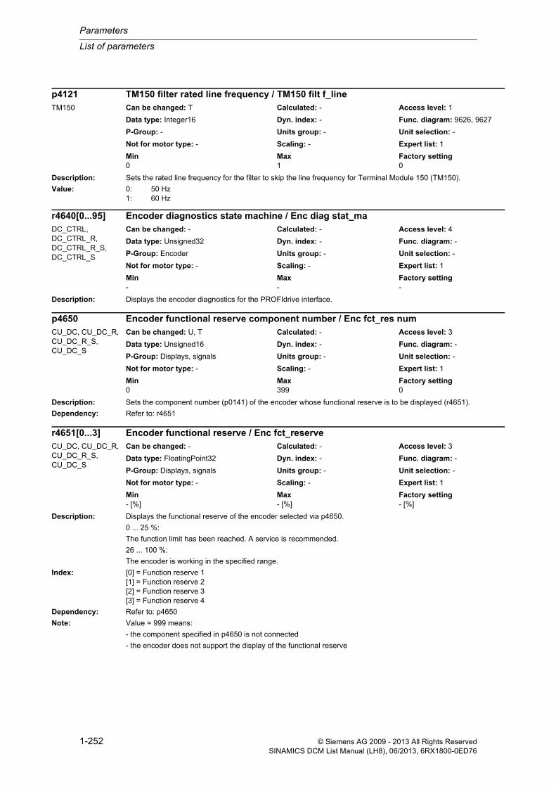
Parameters
List of parameters
1-252 © Siemens AG 2009 - 2013 All Rights ReservedSINAMICS DCM List Manual (LH8), 06/2013, 6RX1800-0ED76
Description: Sets the rated line frequency for the filter to skip the line frequency for Terminal Module 150 (TM150).
Value: 0: 50 Hz1: 60 Hz
Description: Displays the encoder diagnostics for the PROFIdrive interface.
Description: Sets the component number (p0141) of the encoder whose functional reserve is to be displayed (r4651).
Dependency: Refer to: r4651
Description: Displays the functional reserve of the encoder selected via p4650.
0 ... 25 %:
The function limit has been reached. A service is recommended.
26 ... 100 %:
The encoder is working in the specified range.
Index: [0] = Function reserve 1[1] = Function reserve 2[2] = Function reserve 3[3] = Function reserve 4
Dependency: Refer to: p4650
Note: Value = 999 means:
- the component specified in p4650 is not connected
- the encoder does not support the display of the functional reserve
p4121 TM150 filter rated line frequency / TM150 filt f_lineTM150 Can be changed: T Calculated: - Access level: 1
Data type: Integer16 Dyn. index: - Func. diagram: 9626, 9627
P-Group: - Units group: - Unit selection: -
Not for motor type: - Scaling: - Expert list: 1
Min Max Factory setting 0 1 0
r4640[0...95] Encoder diagnostics state machine / Enc diag stat_maDC_CTRL, DC_CTRL_R, DC_CTRL_R_S, DC_CTRL_S
Can be changed: - Calculated: - Access level: 4
Data type: Unsigned32 Dyn. index: - Func. diagram: -
P-Group: Encoder Units group: - Unit selection: -
Not for motor type: - Scaling: - Expert list: 1
Min Max Factory setting - - -
p4650 Encoder functional reserve component number / Enc fct_res numCU_DC, CU_DC_R, CU_DC_R_S, CU_DC_S
Can be changed: U, T Calculated: - Access level: 3
Data type: Unsigned16 Dyn. index: - Func. diagram: -
P-Group: Displays, signals Units group: - Unit selection: -
Not for motor type: - Scaling: - Expert list: 1
Min Max Factory setting 0 399 0
r4651[0...3] Encoder functional reserve / Enc fct_reserveCU_DC, CU_DC_R, CU_DC_R_S, CU_DC_S
Can be changed: - Calculated: - Access level: 3
Data type: FloatingPoint32 Dyn. index: - Func. diagram: -
P-Group: Displays, signals Units group: - Unit selection: -
Not for motor type: - Scaling: - Expert list: 1
Min Max Factory setting - [%] - [%] - [%]

List of parameters
Parameters
1-253© Siemens AG 2009 - 2013 All Rights ReservedSINAMICS DCM List Manual (LH8), 06/2013, 6RX1800-0ED76
Description: Sets the mode to reset the actual value in XIST_ERW (CO: r4653).
Value: 0: Inactive1: Reset with zero mark2: Reset with BICO3: Reset with selected zero mark
Index: [0] = Encoder 1[1] = Encoder 2[2] = -
Dependency: Refer to: r4653, r4654, p4655
Note: If value = 1:
The value in XIST1_ERW is reset when passing every zero mark.
If value = 2:
The value in XIST1_ERW is reset with a 0/1 edge via binector input p4655.
If value = 3:
The value in XIST1_ERW is reset after a 0/1 edge via binector input p4655 when passing the next zero mark.
Description: Display and connector output for the actual value XIST1_ERW.
Index: [0] = Encoder 1[1] = Encoder 2[2] = -
Dependency: Refer to: p4652, r4654, p4655
Description: Display and binector output to reset XIST1_ERW.
Dependency: Refer to: p4652, r4653, p4655
Note: The reset of XIST1_ERW is initiated via binector input p4655.
Binector output r4654 is reset with a 0 signal from binector input p4655.
p4652[0...2] XIST1_ERW reset mode / XIST1_ERW res modeDC_CTRL, DC_CTRL_R, DC_CTRL_R_S, DC_CTRL_S
Can be changed: C1(3) Calculated: - Access level: 3
Data type: Integer16 Dyn. index: - Func. diagram: 4750
P-Group: - Units group: - Unit selection: -
Not for motor type: - Scaling: - Expert list: 1
Min Max Factory setting 0 3 0
r4653[0...2] CO: XIST1_ERW actual value / XIST1_ERW actvalDC_CTRL, DC_CTRL_R, DC_CTRL_R_S, DC_CTRL_S
Can be changed: - Calculated: - Access level: 3
Data type: Unsigned32 Dyn. index: - Func. diagram: 4750
P-Group: Encoder Units group: - Unit selection: -
Not for motor type: - Scaling: - Expert list: 1
Min Max Factory setting - - -
r4654.0...8 CO/BO: XIST1_ERW status / XIST1_ERW statDC_CTRL, DC_CTRL_R, DC_CTRL_R_S, DC_CTRL_S
Can be changed: - Calculated: - Access level: 3
Data type: Unsigned32 Dyn. index: - Func. diagram: 4750
P-Group: Encoder Units group: - Unit selection: -
Not for motor type: - Scaling: - Expert list: 1
Min Max Factory setting - - -
Bit field: Bit Signal name 1 signal 0 signal FP00 Encoder 1 XIST1_ERW reset High Low -08 Encoder 2 XIST1_ERW reset High Low -

Parameters
List of parameters
1-254 © Siemens AG 2009 - 2013 All Rights ReservedSINAMICS DCM List Manual (LH8), 06/2013, 6RX1800-0ED76
Description: Sets the signal source to reset XIST1_ERW (CO: r4653).
Index: [0] = Encoder 1[1] = Encoder 2[2] = -
Dependency: Refer to: p4652, r4653, r4654
Note: The reset of XIST1_ERW depends on the selected mode (p4652).
Description: Sets the filter bandwidth for Sensor Module SMx10 (resolver) and SMx20 (sin/cos).
The value set on the Sensor Module is displayed in r4661.
The Sensor Module hardware only supports the following values:
- 0: The Sensor Module's default is used.
- 50 kHz
- 170 kHz
- 500 kHz
- Unlimited: Only the bandwidth of the operational amplifier is effective.
Index: [0] = Encoder 1[1] = Encoder 2[2] = Reserved
Dependency: Refer to: r4661
Note: A value of zero is displayed if an encoder is not present.
Description: Display of the effective filter bandwidth for Sensor Module SMx10 (resolver) and SMx20 (sin/cos).
The bandwidth of the filter is set using p4660.
Index: [0] = Encoder 1[1] = Encoder 2[2] = Reserved
Dependency: Refer to: p4660
Note: A value of zero is displayed if an encoder is not present.
p4655[0...2] BI: XIST1_ERW reset signal source / XIST1_ERW resS_srcDC_CTRL, DC_CTRL_R, DC_CTRL_R_S, DC_CTRL_S
Can be changed: T Calculated: - Access level: 3
Data type: Unsigned32 / Binary Dyn. index: - Func. diagram: 4750
P-Group: Encoder Units group: - Unit selection: -
Not for motor type: - Scaling: - Expert list: 1
Min Max Factory setting - - 0
p4660[0...2] Sensor Module filter bandwidth / SM Filt_bandwDC_CTRL, DC_CTRL_R, DC_CTRL_R_S, DC_CTRL_S
Can be changed: C2(4) Calculated: - Access level: 3
Data type: FloatingPoint32 Dyn. index: - Func. diagram: -
P-Group: Encoder Units group: - Unit selection: -
Not for motor type: - Scaling: - Expert list: 1
Min Max Factory setting 0.00 [kHz] 20000.00 [kHz] 0.00 [kHz]
r4661[0...2] Sensor Module filter bandwidth display / SM Filt_bandw dispDC_CTRL, DC_CTRL_R, DC_CTRL_R_S, DC_CTRL_S
Can be changed: - Calculated: - Access level: 3
Data type: FloatingPoint32 Dyn. index: - Func. diagram: -
P-Group: Encoder Units group: - Unit selection: -
Not for motor type: - Scaling: - Expert list: 1
Min Max Factory setting - [kHz] - [kHz] - [kHz]

List of parameters
Parameters
1-255© Siemens AG 2009 - 2013 All Rights ReservedSINAMICS DCM List Manual (LH8), 06/2013, 6RX1800-0ED76
Description: Sets the ratio for the LVDT sensor.
Description: Sets the phase for the LVDT sensor.
Description: Sets the permissible tolerance in encoder pulses for the zero mark distance in the context of zero mark monitoring.
Causes fault F3x100 to appear less frequently.
Dependency: Refer to: p0430
Note: The parameter is activated using p0430.21 = 1 (zero mark tolerance).
Description: Sets the positive tolerance window in encoder pulses for limit 1 for the zero mark monitoring.
If the deviation is less than this limit, then the pulse number is not corrected. If it is higher than this limit, fault F3x131 is triggered.
If fault F3x131 is re-parameterized to alarm (A) or no message (N), the encoder pulses which have not been cor-rected are added to the accumulator (p4688). The accumulator can be de-activated using p0437.7.
Dependency: Refer to: p0437, p4688
Note: This monitoring is activated by setting p0437.2 = 1 (position actual value correction).
The positive limit describes additional pulses due to EMC.
p4678[0...n] Analog sensor LVDT ratio / An_sens LVDT ratioDC_CTRL, DC_CTRL_R, DC_CTRL_R_S, DC_CTRL_S
Can be changed: C2(4) Calculated: - Access level: 4
Data type: FloatingPoint32 Dyn. index: EDS, p0140 Func. diagram: -
P-Group: Encoder Units group: - Unit selection: -
Not for motor type: - Scaling: - Expert list: 1
Min Max Factory setting 0.00 [%] 200.00 [%] 50.00 [%]
p4679[0...n] Analog sensor LVDT phase / An_sens LVDT phDC_CTRL, DC_CTRL_R, DC_CTRL_R_S, DC_CTRL_S
Can be changed: C2(4), T Calculated: - Access level: 4
Data type: FloatingPoint32 Dyn. index: EDS, p0140 Func. diagram: -
P-Group: Encoder Units group: - Unit selection: -
Not for motor type: - Scaling: - Expert list: 1
Min Max Factory setting -360.00 [°] 360.00 [°] 0.00 [°]
p4680[0...n] Zero mark monitoring tolerance permissible / ZM_monit tol permDC_CTRL, DC_CTRL_R, DC_CTRL_R_S, DC_CTRL_S
Can be changed: C2(4) Calculated: - Access level: 3
Data type: Unsigned32 Dyn. index: EDS, p0140 Func. diagram: -
P-Group: Encoder Units group: - Unit selection: -
Not for motor type: - Scaling: - Expert list: 1
Min Max Factory setting 0 1000 4
p4681[0...n] Zero mark monitoring tolerance window limit 1 positive / ZM tol lim 1 posDC_CTRL, DC_CTRL_R, DC_CTRL_R_S, DC_CTRL_S
Can be changed: C2(4) Calculated: - Access level: 3
Data type: Unsigned32 Dyn. index: EDS, p0140 Func. diagram: -
P-Group: Encoder Units group: - Unit selection: -
Not for motor type: - Scaling: - Expert list: 1
Min Max Factory setting 0 1000 2

Parameters
List of parameters
1-256 © Siemens AG 2009 - 2013 All Rights ReservedSINAMICS DCM List Manual (LH8), 06/2013, 6RX1800-0ED76
Description: Sets the negative tolerance window in encoder pulses for limit 1 for the zero mark monitoring.
If the deviation is less than this limit, the PPR is not corrected. If it is higher than this limit, fault F3x131 is triggered.
If fault F3x131 is re-parameterized to alarm (A) or no message (N), the encoder pulses which have not been cor-rected are added to the accumulator (p4688). The accumulator can be de-activated using p0437.7.
Dependency: Refer to: p0437, p4681, p4688
Note: This monitoring is activated by setting p0437.2 = 1 (position actual value correction).
For a set value = -1001, the negated value of p4681 is effective.
The negative limit describes the pulses lost due to a covered glass panel in the incremental encoder.
Description: Sets the positive tolerance window in encoder pulses for limit 2 for the zero mark monitoring.
If the zero mark deviation is higher than the tolerance set in p4681 and p4682 and fault F3x131 is re-parameterized to alarm (A) or no message (N), the accumulator p4688 is compared with this parameter and, if applicable, alarm A3x422 is output for 5 seconds.
Dependency: Refer to: p0437, p4681, p4682, p4688
Note: Zero mark monitoring is activated by setting p0437.2 = 1 (position actual value correction).
Description: Sets the negative tolerance window in encoder pulses for limit 2 for the zero mark monitoring.
If the zero mark deviation is higher than the tolerance set in p4681 and p4682 and fault F3x131 is re-parameterized to alarm (A) or no message (N), the accumulator p4688 is compared with this parameter and, if applicable, alarm A3x422 is output for 5 seconds.
Dependency: Refer to: p0437, p4683, p4688
Note: Zero mark monitoring is activated by setting p0437.2 = 1 (position actual value correction).
For a set value = -100001, the negated value of p4683 is effective.
p4682[0...n] Zero mark monitoring tolerance window limit 1 negative / ZM tol lim 1 negDC_CTRL, DC_CTRL_R, DC_CTRL_R_S, DC_CTRL_S
Can be changed: C2(4) Calculated: - Access level: 3
Data type: Integer32 Dyn. index: EDS, p0140 Func. diagram: -
P-Group: Encoder Units group: - Unit selection: -
Not for motor type: - Scaling: - Expert list: 1
Min Max Factory setting -1001 0 -1001
p4683[0...n] Zero mark monitoring tolerance window alarm threshold positive / ZM tol A_thr posDC_CTRL, DC_CTRL_R, DC_CTRL_R_S, DC_CTRL_S
Can be changed: C2(4) Calculated: - Access level: 3
Data type: Unsigned32 Dyn. index: EDS, p0140 Func. diagram: -
P-Group: Encoder Units group: - Unit selection: -
Not for motor type: - Scaling: - Expert list: 1
Min Max Factory setting 0 100000 0
p4684[0...n] Zero mark monitoring tolerance window alarm threshold negative / ZM tol A_thr negDC_CTRL, DC_CTRL_R, DC_CTRL_R_S, DC_CTRL_S
Can be changed: C2(4) Calculated: - Access level: 3
Data type: Integer32 Dyn. index: EDS, p0140 Func. diagram: -
P-Group: Encoder Units group: - Unit selection: -
Not for motor type: - Scaling: - Expert list: 1
Min Max Factory setting -100001 0 -100001

List of parameters
Parameters
1-257© Siemens AG 2009 - 2013 All Rights ReservedSINAMICS DCM List Manual (LH8), 06/2013, 6RX1800-0ED76
Description: Sets the number of current controller clock cycles for mean value generation of the speed actual value.
Note: Value = 0, 1: No mean value generation.
Higher values also mean higher dead times for the speed actual value.
Description: Sets the minimum length for the zero mark.
Dependency: Refer to: p0425, p0437
Note: The value for the minimum length of the zero mark must be set less than p0425.
The parameter is activated using p0437.1 = 1 (zero mark edge detection).
Description: Displays the number of differential pulses for the zero mark monitoring that have accumulated.
If fault F3x131 is re-parameterized to alarm (A) or no message (N), the encoder pulses which have not been cor-rected are added to the accumulator (p4688).
Index: [0] = Encoder 1[1] = Encoder 2[2] = -
Dependency: Refer to: p4681, p4682, p4683, p4684
Note: The display can only be reset to zero.
Description: Displays the encoder status according to PROFIdrive for a squarewave encoder.
Index: [0] = Encoder 1[1] = Encoder 2[2] = -
Note: After alarm A3x422 is output, this parameter is set for 100 ms.
p4685[0...n] Speed actual value mean value generation / n_act mean valDC_CTRL, DC_CTRL_R, DC_CTRL_R_S, DC_CTRL_S
Can be changed: C2(4) Calculated: - Access level: 3
Data type: Unsigned32 Dyn. index: EDS, p0140 Func. diagram: -
P-Group: Encoder Units group: - Unit selection: -
Not for motor type: - Scaling: - Expert list: 1
Min Max Factory setting 0 20 0
p4686[0...n] Zero mark minimum length / ZM min lengthDC_CTRL, DC_CTRL_R, DC_CTRL_R_S, DC_CTRL_S
Can be changed: C2(4) Calculated: - Access level: 3
Data type: Unsigned32 Dyn. index: EDS, p0140 Func. diagram: -
P-Group: Encoder Units group: - Unit selection: -
Not for motor type: - Scaling: - Expert list: 1
Min Max Factory setting 0 10 1
p4688[0...2] CO: Zero mark monitoring differential pulse count / ZM diff_pulse qtyDC_CTRL, DC_CTRL_R, DC_CTRL_R_S, DC_CTRL_S
Can be changed: T Calculated: - Access level: 3
Data type: Integer32 Dyn. index: - Func. diagram: -
P-Group: - Units group: - Unit selection: -
Not for motor type: - Scaling: - Expert list: 1
Min Max Factory setting -2147483648 2147483647 0
r4689[0...2] CO: Squarewave encoder diagnostics / Sq-wave enc diagDC_CTRL, DC_CTRL_R, DC_CTRL_R_S, DC_CTRL_S
Can be changed: - Calculated: - Access level: 4
Data type: Unsigned32 Dyn. index: - Func. diagram: -
P-Group: Encoder Units group: - Unit selection: -
Not for motor type: - Scaling: - Expert list: 1
Min Max Factory setting - - -

Parameters
List of parameters
1-258 © Siemens AG 2009 - 2013 All Rights ReservedSINAMICS DCM List Manual (LH8), 06/2013, 6RX1800-0ED76
Description: Setting to control the trace function.
Value: 0: Stop trace1: Start trace2: Start trace and save values
Index: [0] = Trace 0[1] = Trace 1
Description: Setting to control the measurement function.
Value: 0: Stop measuring function1: Start measuring function2: Measuring function check parameterization3: Start measuring function without enable signals
Description: Sets the options for the trace.
Index: [0] = Trace 0[1] = Trace 1
Dependency: Refer to: p4700
Note: Re bit 00:
0: The trace starts with p4700 as before.
1: When powering up, the trace starts immediately with the saved parameter settings with the start of the time slices.
Description: Displays the actual status of the trace.
p4700[0...1] Trace control / Trace controlCU_DC, CU_DC_R, CU_DC_R_S, CU_DC_S
Can be changed: U, T Calculated: - Access level: 3
Data type: Integer16 Dyn. index: - Func. diagram: -
P-Group: Trace and function generator Units group: - Unit selection: -
Not for motor type: - Scaling: - Expert list: 0
Min Max Factory setting 0 2 0
p4701 Measuring function control / Meas fct ctrlCU_DC, CU_DC_R, CU_DC_R_S, CU_DC_S
Can be changed: U, T Calculated: - Access level: 3
Data type: Integer16 Dyn. index: - Func. diagram: -
P-Group: Trace and function generator Units group: - Unit selection: -
Not for motor type: - Scaling: - Expert list: 0
Min Max Factory setting 0 3 0
p4703[0...1] Trace options / Trace optionsCU_DC, CU_DC_R, CU_DC_R_S, CU_DC_S
Can be changed: T Calculated: - Access level: 3
Data type: Unsigned16 Dyn. index: - Func. diagram: -
P-Group: Trace and function generator Units group: - Unit selection: -
Not for motor type: - Scaling: - Expert list: 0
Min Max Factory setting - - 0000 bin
Bit field: Bit Signal name 1 signal 0 signal FP00 Automatically start trace with time slices Yes No -
r4705[0...1] Trace status / Trace statusCU_DC, CU_DC_R, CU_DC_R_S, CU_DC_S
Can be changed: - Calculated: - Access level: 3
Data type: Integer16 Dyn. index: - Func. diagram: -
P-Group: Trace and function generator Units group: - Unit selection: -
Not for motor type: - Scaling: - Expert list: 0
Min Max Factory setting 0 4 -

List of parameters
Parameters
1-259© Siemens AG 2009 - 2013 All Rights ReservedSINAMICS DCM List Manual (LH8), 06/2013, 6RX1800-0ED76
Value: 0: Trace inactive1: Trace is recording presamples2: Trace is waiting for trigger event3: Trace is recording4: Recording (trace) ended
Index: [0] = Trace 0[1] = Trace 1
Description: Displays the actual status of the measuring function.
Value: 0: Measurement function inactive1: Measuring function parameterization checked2: Measuring function waits for stabilizing time3: Measuring function recording (tracing)4: Measuring function trace ended with error5: Measuring function trace successfully completed
Description: Setting to configure the measurement function.
Value: 0: Standard1: Free meas fct
Note: The parameter cannot be changed when the measurement function has been started (r4706 = 2, 3).
For value = 0:
The system injection point selected to inject the function generator signal is used.
For value = 1:
No system injection point is used.
When using the measuring function in the STARTER commissioning software, the following applies:
A change to a value only becomes effective after first closing and opening the measuring function screen form.
For value = 0:
The master control must be fetched.
There are two fixed and two freely selectable signals for recording.
For value = 1:
Master control does not have to be fetched.
There are four freely selectable signals for recording.
Description: Displays the required memory in bytes for the actual parameterization.
r4706 Measuring function status / Meas fct statusCU_DC, CU_DC_R, CU_DC_R_S, CU_DC_S
Can be changed: - Calculated: - Access level: 3
Data type: Integer16 Dyn. index: - Func. diagram: -
P-Group: Trace and function generator Units group: - Unit selection: -
Not for motor type: - Scaling: - Expert list: 0
Min Max Factory setting 0 5 -
p4707 Measurement function configuration / Meas fct configCU_DC, CU_DC_R, CU_DC_R_S, CU_DC_S
Can be changed: U, T Calculated: - Access level: 4
Data type: Integer16 Dyn. index: - Func. diagram: -
P-Group: - Units group: - Unit selection: -
Not for motor type: - Scaling: - Expert list: 1
Min Max Factory setting 0 1 0
r4708[0...1] Trace memory space required / Trace mem requiredCU_DC, CU_DC_R, CU_DC_R_S, CU_DC_S
Can be changed: - Calculated: - Access level: 3
Data type: Unsigned32 Dyn. index: - Func. diagram: -
P-Group: Trace and function generator Units group: - Unit selection: -
Not for motor type: - Scaling: - Expert list: 0
Min Max Factory setting - - -
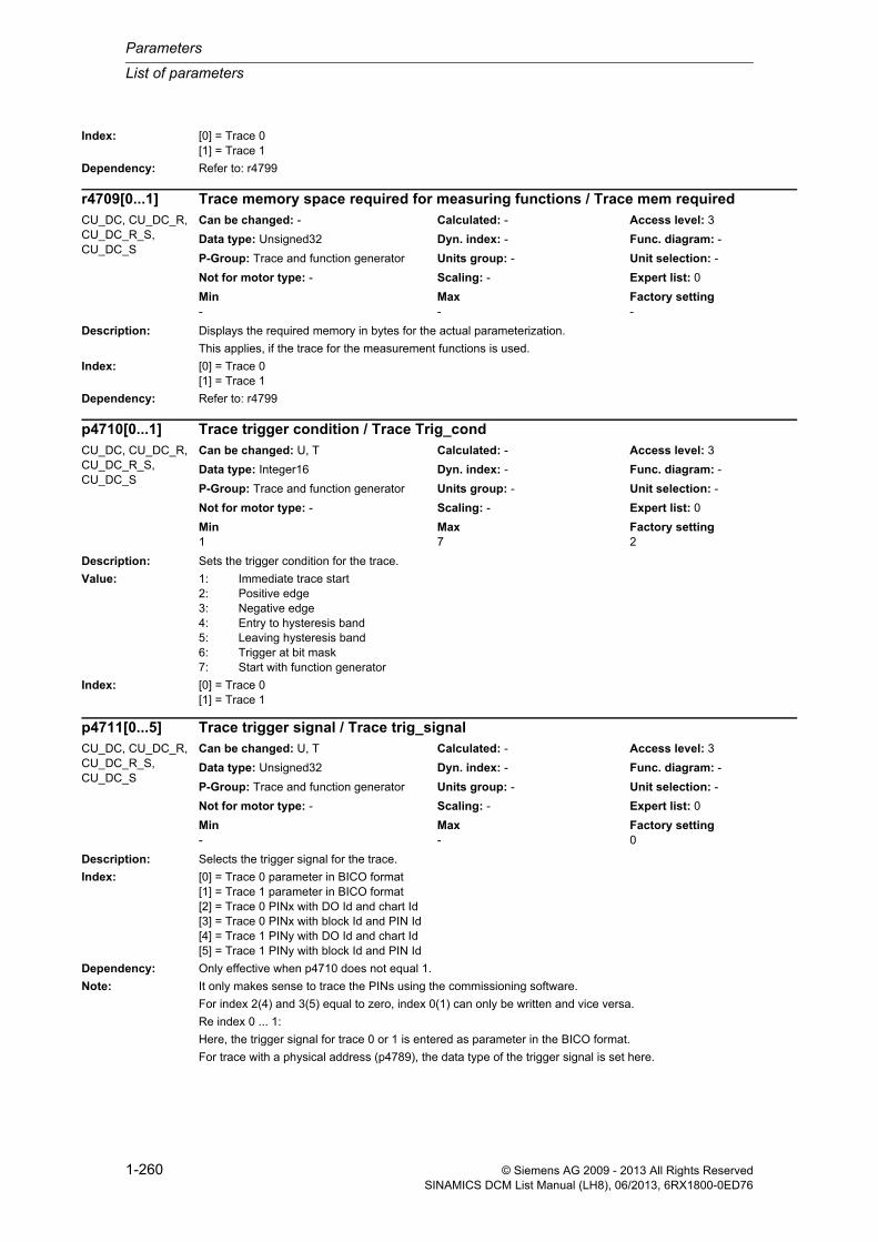
Parameters
List of parameters
1-260 © Siemens AG 2009 - 2013 All Rights ReservedSINAMICS DCM List Manual (LH8), 06/2013, 6RX1800-0ED76
Index: [0] = Trace 0[1] = Trace 1
Dependency: Refer to: r4799
Description: Displays the required memory in bytes for the actual parameterization.
This applies, if the trace for the measurement functions is used.
Index: [0] = Trace 0[1] = Trace 1
Dependency: Refer to: r4799
Description: Sets the trigger condition for the trace.
Value: 1: Immediate trace start2: Positive edge3: Negative edge4: Entry to hysteresis band5: Leaving hysteresis band6: Trigger at bit mask7: Start with function generator
Index: [0] = Trace 0[1] = Trace 1
Description: Selects the trigger signal for the trace.
Index: [0] = Trace 0 parameter in BICO format[1] = Trace 1 parameter in BICO format[2] = Trace 0 PINx with DO Id and chart Id[3] = Trace 0 PINx with block Id and PIN Id[4] = Trace 1 PINy with DO Id and chart Id[5] = Trace 1 PINy with block Id and PIN Id
Dependency: Only effective when p4710 does not equal 1.
Note: It only makes sense to trace the PINs using the commissioning software.
For index 2(4) and 3(5) equal to zero, index 0(1) can only be written and vice versa.
Re index 0 ... 1:
Here, the trigger signal for trace 0 or 1 is entered as parameter in the BICO format.
For trace with a physical address (p4789), the data type of the trigger signal is set here.
r4709[0...1] Trace memory space required for measuring functions / Trace mem requiredCU_DC, CU_DC_R, CU_DC_R_S, CU_DC_S
Can be changed: - Calculated: - Access level: 3
Data type: Unsigned32 Dyn. index: - Func. diagram: -
P-Group: Trace and function generator Units group: - Unit selection: -
Not for motor type: - Scaling: - Expert list: 0
Min Max Factory setting - - -
p4710[0...1] Trace trigger condition / Trace Trig_condCU_DC, CU_DC_R, CU_DC_R_S, CU_DC_S
Can be changed: U, T Calculated: - Access level: 3
Data type: Integer16 Dyn. index: - Func. diagram: -
P-Group: Trace and function generator Units group: - Unit selection: -
Not for motor type: - Scaling: - Expert list: 0
Min Max Factory setting 1 7 2
p4711[0...5] Trace trigger signal / Trace trig_signalCU_DC, CU_DC_R, CU_DC_R_S, CU_DC_S
Can be changed: U, T Calculated: - Access level: 3
Data type: Unsigned32 Dyn. index: - Func. diagram: -
P-Group: Trace and function generator Units group: - Unit selection: -
Not for motor type: - Scaling: - Expert list: 0
Min Max Factory setting - - 0

List of parameters
Parameters
1-261© Siemens AG 2009 - 2013 All Rights ReservedSINAMICS DCM List Manual (LH8), 06/2013, 6RX1800-0ED76
Re index 2 ...3:
The triggering PIN for trace 0 is entered here.
Index 2 bit 31 ... 16: Number of the Drive Object (DO), bit 15 ... 0: Number of the chart
Index 3 bit 31 ... 16: Number of the block, bit 15 ... 0: Number of the PIN
Re index 4 ... 5:
The triggering PIN for trace 1 is entered here.
Index 4 bit 31 ... 16: Number of the Drive Object (DO), bit 15 ... 0: Number of the chart
Index 5 bit 31 ... 16: Number of the block, bit 15 ... 0: Number of the PIN
Description: Sets the trigger threshold for the trace.
Index: [0] = Trace 0[1] = Trace 1
Dependency: Only effective when p4710 = 2, 3.
Description: Sets the first trigger threshold for trigger via tolerance band.
Index: [0] = Trace 0[1] = Trace 1
Dependency: Only effective when p4710 = 4, 5.
Description: Sets the second trigger threshold for trigger via tolerance band
Index: [0] = Trace 0[1] = Trace 1
Dependency: Only effective when p4710 = 4, 5.
Description: Sets the bit mask for the bit mask trigger.
p4712[0...1] Trace trigger threshold / Trace trig_threshCU_DC, CU_DC_R, CU_DC_R_S, CU_DC_S
Can be changed: U, T Calculated: - Access level: 3
Data type: FloatingPoint32 Dyn. index: - Func. diagram: -
P-Group: Trace and function generator Units group: - Unit selection: -
Not for motor type: - Scaling: - Expert list: 0
Min Max Factory setting -340.28235E36 340.28235E36 0.00
p4713[0...1] Trace tolerance band trigger threshold 1 / Trace trig thr 1CU_DC, CU_DC_R, CU_DC_R_S, CU_DC_S
Can be changed: U, T Calculated: - Access level: 3
Data type: FloatingPoint32 Dyn. index: - Func. diagram: -
P-Group: Trace and function generator Units group: - Unit selection: -
Not for motor type: - Scaling: - Expert list: 0
Min Max Factory setting -340.28235E36 340.28235E36 0.00
p4714[0...1] Trace tolerance band trigger threshold 2 / Trace trig thr 2CU_DC, CU_DC_R, CU_DC_R_S, CU_DC_S
Can be changed: U, T Calculated: - Access level: 3
Data type: FloatingPoint32 Dyn. index: - Func. diagram: -
P-Group: Trace and function generator Units group: - Unit selection: -
Not for motor type: - Scaling: - Expert list: 0
Min Max Factory setting -340.28235E36 340.28235E36 0.00
p4715[0...1] Trace bit mask trigger, bit mask / Trace trig maskCU_DC, CU_DC_R, CU_DC_R_S, CU_DC_S
Can be changed: U, T Calculated: - Access level: 3
Data type: Unsigned32 Dyn. index: - Func. diagram: -
P-Group: Trace and function generator Units group: - Unit selection: -
Not for motor type: - Scaling: - Expert list: 0
Min Max Factory setting 0 4294967295 0

Parameters
List of parameters
1-262 © Siemens AG 2009 - 2013 All Rights ReservedSINAMICS DCM List Manual (LH8), 06/2013, 6RX1800-0ED76
Index: [0] = Trace 0[1] = Trace 1
Dependency: Only effective when p4710 = 6.
Description: Sets the trigger condition for bit mask trigger.
Index: [0] = Trace 0[1] = Trace 1
Dependency: Only effective when p4710 = 6.
Description: Displays the trigger index in the trace buffer. The trigger event occurred at this point.
Index: [0] = Trace 0[1] = Trace 1
Dependency: Only valid when p4705 = 4.
Description: Sets the recording cycle for the trace.
Index: [0] = Trace 0[1] = Trace 1
Description: Sets the recording time for the trace.
Index: [0] = Trace 0[1] = Trace 1
p4716[0...1] Trace bit mask trigger trigger condition / Trace Trig_condCU_DC, CU_DC_R, CU_DC_R_S, CU_DC_S
Can be changed: U, T Calculated: - Access level: 3
Data type: Unsigned32 Dyn. index: - Func. diagram: -
P-Group: Trace and function generator Units group: - Unit selection: -
Not for motor type: - Scaling: - Expert list: 0
Min Max Factory setting 0 4294967295 0
r4719[0...1] Trace trigger index / Trace Trig_indexCU_DC, CU_DC_R, CU_DC_R_S, CU_DC_S
Can be changed: - Calculated: - Access level: 3
Data type: Unsigned32 Dyn. index: - Func. diagram: -
P-Group: Trace and function generator Units group: - Unit selection: -
Not for motor type: - Scaling: - Expert list: 0
Min Max Factory setting - - -
p4720[0...1] Trace recording cycle / Trace record_cycCU_DC, CU_DC_R, CU_DC_R_S, CU_DC_S
Can be changed: U, T Calculated: - Access level: 3
Data type: FloatingPoint32 Dyn. index: - Func. diagram: -
P-Group: Trace and function generator Units group: - Unit selection: -
Not for motor type: - Scaling: - Expert list: 0
Min Max Factory setting 0.000 [ms] 60000.000 [ms] 1.000 [ms]
p4721[0...1] Trace recording time / Trace record_timeCU_DC, CU_DC_R, CU_DC_R_S, CU_DC_S
Can be changed: U, T Calculated: - Access level: 3
Data type: FloatingPoint32 Dyn. index: - Func. diagram: -
P-Group: Trace and function generator Units group: - Unit selection: -
Not for motor type: - Scaling: - Expert list: 0
Min Max Factory setting 0.000 [ms] 3600000.000 [ms] 1000.000 [ms]

List of parameters
Parameters
1-263© Siemens AG 2009 - 2013 All Rights ReservedSINAMICS DCM List Manual (LH8), 06/2013, 6RX1800-0ED76
Description: Sets the trigger delay for the trace.
Trigger delay < 0:
Pretrigger: Tracing (recording) starts the selected time before the trigger event actually occurs.
Trigger delay > 0:
Post trigger: Tracing does not start until the set time after the trigger event.
Index: [0] = Trace 0[1] = Trace 1
Description: Sets the time slice cycle in which the trace is called.
Index: [0] = Trace 0[1] = Trace 1
Description: Sets the averaging in the time range for the trace.
Index: [0] = Trace 0[1] = Trace 1
Description: Displays the recorded data type 1 for the trace.
Index: [0] = Trace 0[1] = Trace 1
p4722[0...1] Trace trigger delay / Trace trig_delayCU_DC, CU_DC_R, CU_DC_R_S, CU_DC_S
Can be changed: U, T Calculated: - Access level: 3
Data type: FloatingPoint32 Dyn. index: - Func. diagram: -
P-Group: Trace and function generator Units group: - Unit selection: -
Not for motor type: - Scaling: - Expert list: 0
Min Max Factory setting -3600000.000 [ms] 3600000.000 [ms] 0.000 [ms]
p4723[0...1] Trace time slice cycle / Trace cycleCU_DC, CU_DC_R, CU_DC_R_S, CU_DC_S
Can be changed: U, T Calculated: - Access level: 3
Data type: FloatingPoint32 Dyn. index: - Func. diagram: -
P-Group: Trace and function generator Units group: - Unit selection: -
Not for motor type: - Scaling: - Expert list: 0
Min Max Factory setting 0.03125 [ms] 4.00000 [ms] 0.12500 [ms]
p4724[0...1] Trace average in the time range / Trace averageCU_DC, CU_DC_R, CU_DC_R_S, CU_DC_S
Can be changed: U, T Calculated: - Access level: 3
Data type: Unsigned8 Dyn. index: - Func. diagram: -
P-Group: Trace and function generator Units group: - Unit selection: -
Not for motor type: - Scaling: - Expert list: 0
Min Max Factory setting 0000 bin 0001 bin 0000 bin
r4725[0...1] Trace data type 1 traced / Trace rec type 1CU_DC, CU_DC_R, CU_DC_R_S, CU_DC_S
Can be changed: - Calculated: - Access level: 3
Data type: Unsigned32 Dyn. index: - Func. diagram: -
P-Group: Trace and function generator Units group: - Unit selection: -
Not for motor type: - Scaling: - Expert list: 0
Min Max Factory setting - - -

Parameters
List of parameters
1-264 © Siemens AG 2009 - 2013 All Rights ReservedSINAMICS DCM List Manual (LH8), 06/2013, 6RX1800-0ED76
Description: Displays the recorded data type 2 for the trace.
Index: [0] = Trace 0[1] = Trace 1
Description: Displays the recorded data type 3 for the trace.
Index: [0] = Trace 0[1] = Trace 1
Description: Displays the recorded data type 4 for the trace.
Index: [0] = Trace 0[1] = Trace 1
Description: Displays the number of traced values for each signal.
Index: [0] = Trace 0[1] = Trace 1
Dependency: Only valid when p4705 = 4.
r4726[0...1] Trace data type 2 traced / Trace rec type 2CU_DC, CU_DC_R, CU_DC_R_S, CU_DC_S
Can be changed: - Calculated: - Access level: 3
Data type: Unsigned32 Dyn. index: - Func. diagram: -
P-Group: Trace and function generator Units group: - Unit selection: -
Not for motor type: - Scaling: - Expert list: 0
Min Max Factory setting - - -
r4727[0...1] Trace data type 3 traced / Trace rec type 3CU_DC, CU_DC_R, CU_DC_R_S, CU_DC_S
Can be changed: - Calculated: - Access level: 3
Data type: Unsigned32 Dyn. index: - Func. diagram: -
P-Group: Trace and function generator Units group: - Unit selection: -
Not for motor type: - Scaling: - Expert list: 0
Min Max Factory setting - - -
r4728[0...1] Trace data type 4 traced / Trace rec type 4CU_DC, CU_DC_R, CU_DC_R_S, CU_DC_S
Can be changed: - Calculated: - Access level: 3
Data type: Unsigned32 Dyn. index: - Func. diagram: -
P-Group: Trace and function generator Units group: - Unit selection: -
Not for motor type: - Scaling: - Expert list: 0
Min Max Factory setting - - -
r4729[0...1] Trace number of recorded values / Trace rec valuesCU_DC, CU_DC_R, CU_DC_R_S, CU_DC_S
Can be changed: - Calculated: - Access level: 3
Data type: Unsigned32 Dyn. index: - Func. diagram: -
P-Group: Trace and function generator Units group: - Unit selection: -
Not for motor type: - Scaling: - Expert list: 0
Min Max Factory setting - - -

List of parameters
Parameters
1-265© Siemens AG 2009 - 2013 All Rights ReservedSINAMICS DCM List Manual (LH8), 06/2013, 6RX1800-0ED76
Description: Selects the first signal to be traced.
Index: [0] = Trace 0 parameter in BICO format[1] = Trace 1 parameter in BICO format[2] = Trace 0 PINx with DO Id and chart Id[3] = Trace 0 PINx with block Id and PIN Id[4] = Trace 1 PINy with DO Id and chart Id[5] = Trace 1 PINy with block Id and PIN Id
Description: Selects the second signal to be traced.
Index: [0] = Trace 0 parameter in BICO format[1] = Trace 1 parameter in BICO format[2] = Trace 0 PINx with DO Id and chart Id[3] = Trace 0 PINx with block Id and PIN Id[4] = Trace 1 PINy with DO Id and chart Id[5] = Trace 1 PINy with block Id and PIN Id
Description: Selects the third signal to be traced.
Index: [0] = Trace 0 parameter in BICO format[1] = Trace 1 parameter in BICO format[2] = Trace 0 PINx with DO Id and chart Id[3] = Trace 0 PINx with block Id and PIN Id[4] = Trace 1 PINy with DO Id and chart Id[5] = Trace 1 PINy with block Id and PIN Id
Description: Selects the fourth signal to be traced.
p4730[0...5] Trace record signal 0 / Trace record sig 0CU_DC, CU_DC_R, CU_DC_R_S, CU_DC_S
Can be changed: U, T Calculated: - Access level: 3
Data type: Unsigned32 Dyn. index: - Func. diagram: -
P-Group: Trace and function generator Units group: - Unit selection: -
Not for motor type: - Scaling: - Expert list: 0
Min Max Factory setting - - 0
p4731[0...5] Trace record signal 1 / Trace record sig 1CU_DC, CU_DC_R, CU_DC_R_S, CU_DC_S
Can be changed: U, T Calculated: - Access level: 3
Data type: Unsigned32 Dyn. index: - Func. diagram: -
P-Group: Trace and function generator Units group: - Unit selection: -
Not for motor type: - Scaling: - Expert list: 0
Min Max Factory setting - - 0
p4732[0...5] Trace record signal 2 / Trace record sig 2CU_DC, CU_DC_R, CU_DC_R_S, CU_DC_S
Can be changed: U, T Calculated: - Access level: 3
Data type: Unsigned32 Dyn. index: - Func. diagram: -
P-Group: Trace and function generator Units group: - Unit selection: -
Not for motor type: - Scaling: - Expert list: 0
Min Max Factory setting - - 0
p4733[0...5] Trace record signal 3 / Trace record sig 3CU_DC, CU_DC_R, CU_DC_R_S, CU_DC_S
Can be changed: U, T Calculated: - Access level: 3
Data type: Unsigned32 Dyn. index: - Func. diagram: -
P-Group: Trace and function generator Units group: - Unit selection: -
Not for motor type: - Scaling: - Expert list: 0
Min Max Factory setting - - 0

Parameters
List of parameters
1-266 © Siemens AG 2009 - 2013 All Rights ReservedSINAMICS DCM List Manual (LH8), 06/2013, 6RX1800-0ED76
Index: [0] = Trace 0 parameter in BICO format[1] = Trace 1 parameter in BICO format[2] = Trace 0 PINx with DO Id and chart Id[3] = Trace 0 PINx with block Id and PIN Id[4] = Trace 1 PINy with DO Id and chart Id[5] = Trace 1 PINy with block Id and PIN Id
Description: Selects the fifth signal to be traced.
Index: [0] = Trace 0 parameter in BICO format[1] = Trace 1 parameter in BICO format[2] = Trace 0 PINx with DO Id and chart Id[3] = Trace 0 PINx with block Id and PIN Id[4] = Trace 1 PINy with DO Id and chart Id[5] = Trace 1 PINy with block Id and PIN Id
Description: Selects the sixth signal to be traced.
Index: [0] = Trace 0 parameter in BICO format[1] = Trace 1 parameter in BICO format[2] = Trace 0 PINx with DO Id and chart Id[3] = Trace 0 PINx with block Id and PIN Id[4] = Trace 1 PINy with DO Id and chart Id[5] = Trace 1 PINy with block Id and PIN Id
Description: Selects the seventh signal to be traced.
Index: [0] = Trace 0 parameter in BICO format[1] = Trace 1 parameter in BICO format[2] = Trace 0 PINx with DO Id and chart Id[3] = Trace 0 PINx with block Id and PIN Id[4] = Trace 1 PINy with DO Id and chart Id[5] = Trace 1 PINy with block Id and PIN Id
p4734[0...5] Trace record signal 4 / Trace record sig 4CU_DC, CU_DC_R, CU_DC_R_S, CU_DC_S
Can be changed: U, T Calculated: - Access level: 3
Data type: Unsigned32 Dyn. index: - Func. diagram: -
P-Group: Trace and function generator Units group: - Unit selection: -
Not for motor type: - Scaling: - Expert list: 0
Min Max Factory setting - - 0
p4735[0...5] Trace record signal 5 / Trace record sig 5CU_DC, CU_DC_R, CU_DC_R_S, CU_DC_S
Can be changed: U, T Calculated: - Access level: 3
Data type: Unsigned32 Dyn. index: - Func. diagram: -
P-Group: Trace and function generator Units group: - Unit selection: -
Not for motor type: - Scaling: - Expert list: 0
Min Max Factory setting - - 0
p4736[0...5] Trace record signal 6 / Trace record sig 6CU_DC, CU_DC_R, CU_DC_R_S, CU_DC_S
Can be changed: U, T Calculated: - Access level: 3
Data type: Unsigned32 Dyn. index: - Func. diagram: -
P-Group: Trace and function generator Units group: - Unit selection: -
Not for motor type: - Scaling: - Expert list: 0
Min Max Factory setting - - 0
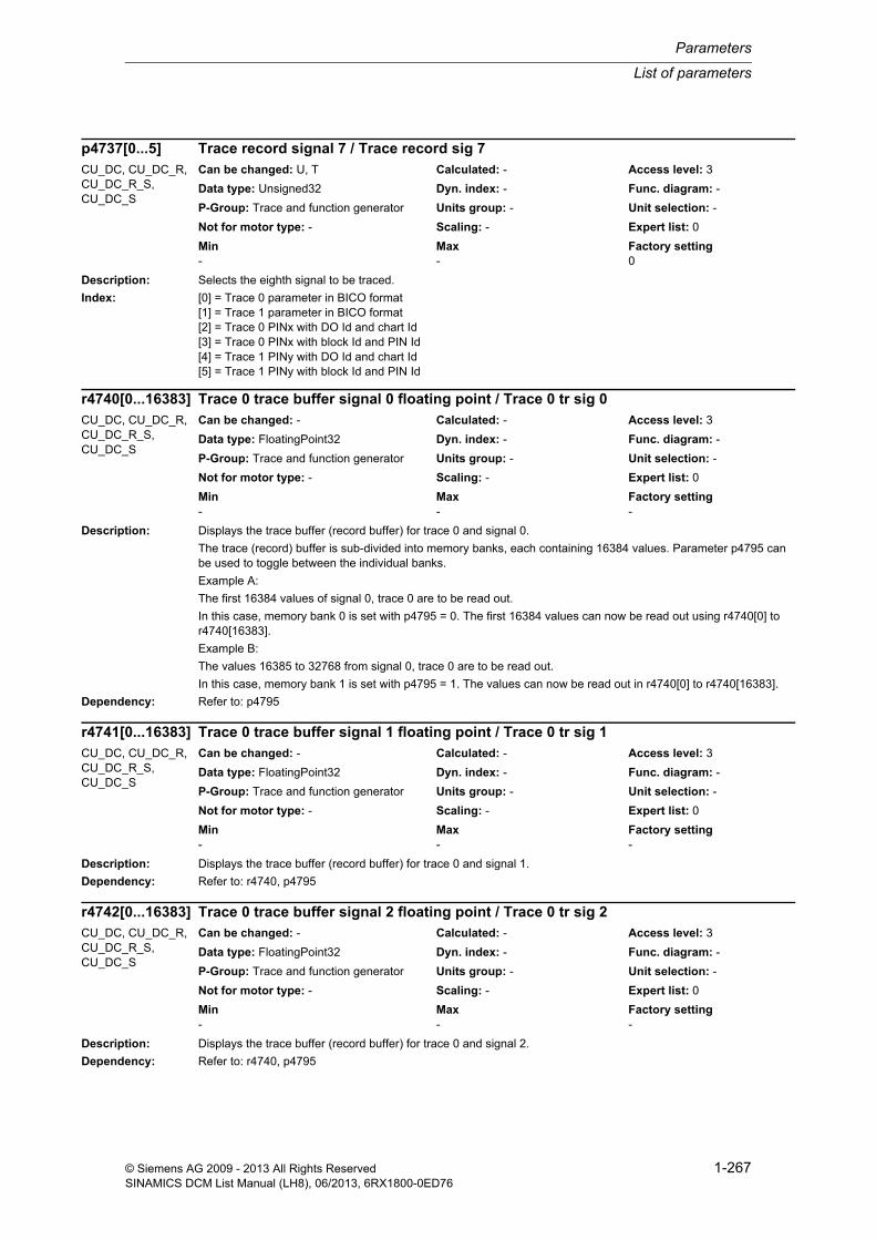
List of parameters
Parameters
1-267© Siemens AG 2009 - 2013 All Rights ReservedSINAMICS DCM List Manual (LH8), 06/2013, 6RX1800-0ED76
Description: Selects the eighth signal to be traced.
Index: [0] = Trace 0 parameter in BICO format[1] = Trace 1 parameter in BICO format[2] = Trace 0 PINx with DO Id and chart Id[3] = Trace 0 PINx with block Id and PIN Id[4] = Trace 1 PINy with DO Id and chart Id[5] = Trace 1 PINy with block Id and PIN Id
Description: Displays the trace buffer (record buffer) for trace 0 and signal 0.
The trace (record) buffer is sub-divided into memory banks, each containing 16384 values. Parameter p4795 can be used to toggle between the individual banks.
Example A:
The first 16384 values of signal 0, trace 0 are to be read out.
In this case, memory bank 0 is set with p4795 = 0. The first 16384 values can now be read out using r4740[0] to r4740[16383].
Example B:
The values 16385 to 32768 from signal 0, trace 0 are to be read out.
In this case, memory bank 1 is set with p4795 = 1. The values can now be read out in r4740[0] to r4740[16383].
Dependency: Refer to: p4795
Description: Displays the trace buffer (record buffer) for trace 0 and signal 1.
Dependency: Refer to: r4740, p4795
Description: Displays the trace buffer (record buffer) for trace 0 and signal 2.
Dependency: Refer to: r4740, p4795
p4737[0...5] Trace record signal 7 / Trace record sig 7CU_DC, CU_DC_R, CU_DC_R_S, CU_DC_S
Can be changed: U, T Calculated: - Access level: 3
Data type: Unsigned32 Dyn. index: - Func. diagram: -
P-Group: Trace and function generator Units group: - Unit selection: -
Not for motor type: - Scaling: - Expert list: 0
Min Max Factory setting - - 0
r4740[0...16383] Trace 0 trace buffer signal 0 floating point / Trace 0 tr sig 0CU_DC, CU_DC_R, CU_DC_R_S, CU_DC_S
Can be changed: - Calculated: - Access level: 3
Data type: FloatingPoint32 Dyn. index: - Func. diagram: -
P-Group: Trace and function generator Units group: - Unit selection: -
Not for motor type: - Scaling: - Expert list: 0
Min Max Factory setting - - -
r4741[0...16383] Trace 0 trace buffer signal 1 floating point / Trace 0 tr sig 1CU_DC, CU_DC_R, CU_DC_R_S, CU_DC_S
Can be changed: - Calculated: - Access level: 3
Data type: FloatingPoint32 Dyn. index: - Func. diagram: -
P-Group: Trace and function generator Units group: - Unit selection: -
Not for motor type: - Scaling: - Expert list: 0
Min Max Factory setting - - -
r4742[0...16383] Trace 0 trace buffer signal 2 floating point / Trace 0 tr sig 2CU_DC, CU_DC_R, CU_DC_R_S, CU_DC_S
Can be changed: - Calculated: - Access level: 3
Data type: FloatingPoint32 Dyn. index: - Func. diagram: -
P-Group: Trace and function generator Units group: - Unit selection: -
Not for motor type: - Scaling: - Expert list: 0
Min Max Factory setting - - -

Parameters
List of parameters
1-268 © Siemens AG 2009 - 2013 All Rights ReservedSINAMICS DCM List Manual (LH8), 06/2013, 6RX1800-0ED76
Description: Displays the trace buffer (record buffer) for trace 0 and signal 3.
Dependency: Refer to: r4740, p4795
Description: Displays the trace buffer (record buffer) for trace 0 and signal 4.
Dependency: Refer to: r4740, p4795
Description: Displays the trace buffer (record buffer) for trace 0 and signal 5.
Dependency: Refer to: r4740, p4795
Description: Displays the trace buffer (record buffer) for trace 0 and signal 6.
Dependency: Refer to: r4740, p4795
Description: Displays the trace buffer (record buffer) for trace 0 and signal 7.
Dependency: Refer to: r4740, p4795
r4743[0...16383] Trace 0 trace buffer signal 3 floating point / Trace 0 tr sig 3CU_DC, CU_DC_R, CU_DC_R_S, CU_DC_S
Can be changed: - Calculated: - Access level: 3
Data type: FloatingPoint32 Dyn. index: - Func. diagram: -
P-Group: Trace and function generator Units group: - Unit selection: -
Not for motor type: - Scaling: - Expert list: 0
Min Max Factory setting - - -
r4744[0...16383] Trace 0 trace buffer signal 4 floating point / Trace 0 tr sig 4CU_DC, CU_DC_R, CU_DC_R_S, CU_DC_S
Can be changed: - Calculated: - Access level: 3
Data type: FloatingPoint32 Dyn. index: - Func. diagram: -
P-Group: Trace and function generator Units group: - Unit selection: -
Not for motor type: - Scaling: - Expert list: 0
Min Max Factory setting - - -
r4745[0...16383] Trace 0 trace buffer signal 5 floating point / Trace 0 tr sig 5CU_DC, CU_DC_R, CU_DC_R_S, CU_DC_S
Can be changed: - Calculated: - Access level: 3
Data type: FloatingPoint32 Dyn. index: - Func. diagram: -
P-Group: Trace and function generator Units group: - Unit selection: -
Not for motor type: - Scaling: - Expert list: 0
Min Max Factory setting - - -
r4746[0...16383] Trace 0 trace buffer signal 6 floating point / Trace 0 tr sig 6CU_DC, CU_DC_R, CU_DC_R_S, CU_DC_S
Can be changed: - Calculated: - Access level: 3
Data type: FloatingPoint32 Dyn. index: - Func. diagram: -
P-Group: Trace and function generator Units group: - Unit selection: -
Not for motor type: - Scaling: - Expert list: 0
Min Max Factory setting - - -
r4747[0...16383] Trace 0 trace buffer signal 7 floating point / Trace 0 tr sig 7CU_DC, CU_DC_R, CU_DC_R_S, CU_DC_S
Can be changed: - Calculated: - Access level: 3
Data type: FloatingPoint32 Dyn. index: - Func. diagram: -
P-Group: Trace and function generator Units group: - Unit selection: -
Not for motor type: - Scaling: - Expert list: 0
Min Max Factory setting - - -

List of parameters
Parameters
1-269© Siemens AG 2009 - 2013 All Rights ReservedSINAMICS DCM List Manual (LH8), 06/2013, 6RX1800-0ED76
Description: Displays the trace buffer (record buffer) for trace 1 and signal 0.
Dependency: Refer to: r4740, p4795
Description: Displays the trace buffer (record buffer) for trace 1 and signal 1.
Dependency: Refer to: r4740, p4795
Description: Displays the trace buffer (record buffer) for trace 1 and signal 2.
Dependency: Refer to: r4740, p4795
Description: Displays the trace buffer (record buffer) for trace 1 and signal 3.
Dependency: Refer to: r4740, p4795
Description: Displays the trace buffer (record buffer) for trace 1 and signal 4.
Dependency: Refer to: r4740, p4795
r4750[0...16383] Trace 1 trace buffer signal 0 floating point / Trace 1 trace sig0CU_DC, CU_DC_R, CU_DC_R_S, CU_DC_S
Can be changed: - Calculated: - Access level: 3
Data type: FloatingPoint32 Dyn. index: - Func. diagram: -
P-Group: Trace and function generator Units group: - Unit selection: -
Not for motor type: - Scaling: - Expert list: 0
Min Max Factory setting - - -
r4751[0...16383] Trace 1 trace buffer signal 1 floating point / Trace 1 tr sig 1CU_DC, CU_DC_R, CU_DC_R_S, CU_DC_S
Can be changed: - Calculated: - Access level: 3
Data type: FloatingPoint32 Dyn. index: - Func. diagram: -
P-Group: Trace and function generator Units group: - Unit selection: -
Not for motor type: - Scaling: - Expert list: 0
Min Max Factory setting - - -
r4752[0...16383] Trace 1 trace buffer signal 2 floating point / Trace 1 tr sig 2CU_DC, CU_DC_R, CU_DC_R_S, CU_DC_S
Can be changed: - Calculated: - Access level: 3
Data type: FloatingPoint32 Dyn. index: - Func. diagram: -
P-Group: Trace and function generator Units group: - Unit selection: -
Not for motor type: - Scaling: - Expert list: 0
Min Max Factory setting - - -
r4753[0...16383] Trace 1 trace buffer signal 3 floating point / Trace 1 tr sig 3CU_DC, CU_DC_R, CU_DC_R_S, CU_DC_S
Can be changed: - Calculated: - Access level: 3
Data type: FloatingPoint32 Dyn. index: - Func. diagram: -
P-Group: Trace and function generator Units group: - Unit selection: -
Not for motor type: - Scaling: - Expert list: 0
Min Max Factory setting - - -
r4754[0...16383] Trace 1 trace buffer signal 4 floating point / Trace 1 tr sig 4CU_DC, CU_DC_R, CU_DC_R_S, CU_DC_S
Can be changed: - Calculated: - Access level: 3
Data type: FloatingPoint32 Dyn. index: - Func. diagram: -
P-Group: Trace and function generator Units group: - Unit selection: -
Not for motor type: - Scaling: - Expert list: 0
Min Max Factory setting - - -

Parameters
List of parameters
1-270 © Siemens AG 2009 - 2013 All Rights ReservedSINAMICS DCM List Manual (LH8), 06/2013, 6RX1800-0ED76
Description: Displays the trace buffer (record buffer) for trace 1 and signal 5.
Dependency: Refer to: r4740, p4795
Description: Displays the trace buffer (record buffer) for trace 1 and signal 6.
Dependency: Refer to: r4740, p4795
Description: Displays the trace buffer (record buffer) for trace 1 and signal 7.
Dependency: Refer to: r4740, p4795
Description: Displays the trace buffer (record buffer) for trace 0 and signal 0 as integer number.
Note: For signals, data type I32 or U32, the trace buffer is assigned as follows:
r4760[0] = value 0
r4760[1] = value 1
...
r4760[8191] = value 8191
For signals, data type I16 or U16, the trace buffer is assigned as follows:
r4760[0] = value 0 (bit 31 ... 16) and value 1 (bit 15 ... 0)
r4760[1] = value 2 (bit 31 ... 16) and value 3 (bit 15 ... 0)
...
r4760[8191] = value 16382 (bit 31 ... 16) and value 16383 (bit 15 ... 0)
For signals, data type I8 or U8, the trace buffer is assigned as follows:
r4760[0] = value 0 (bit 31 ... 24) value 1 (bit 23 ... 16) value 2 (bit 15 ... 8) value 3 (bit 7 ... 0)
r4755[0...16383] Trace 1 trace buffer signal 5 floating point / Trace 1 tr sig 5CU_DC, CU_DC_R, CU_DC_R_S, CU_DC_S
Can be changed: - Calculated: - Access level: 3
Data type: FloatingPoint32 Dyn. index: - Func. diagram: -
P-Group: Trace and function generator Units group: - Unit selection: -
Not for motor type: - Scaling: - Expert list: 0
Min Max Factory setting - - -
r4756[0...16383] Trace 1 trace buffer signal 6 floating point / Trace 1 tr sig 6CU_DC, CU_DC_R, CU_DC_R_S, CU_DC_S
Can be changed: - Calculated: - Access level: 3
Data type: FloatingPoint32 Dyn. index: - Func. diagram: -
P-Group: Trace and function generator Units group: - Unit selection: -
Not for motor type: - Scaling: - Expert list: 0
Min Max Factory setting - - -
r4757[0...16383] Trace 1 trace buffer signal 7 floating point / Trace 1 tr sig 7CU_DC, CU_DC_R, CU_DC_R_S, CU_DC_S
Can be changed: - Calculated: - Access level: 3
Data type: FloatingPoint32 Dyn. index: - Func. diagram: -
P-Group: Trace and function generator Units group: - Unit selection: -
Not for motor type: - Scaling: - Expert list: 0
Min Max Factory setting - - -
r4760[0...16383] Trace 0 trace buffer signal 0 / Trace 0 tr sig 0CU_DC, CU_DC_R, CU_DC_R_S, CU_DC_S
Can be changed: - Calculated: - Access level: 3
Data type: Unsigned32 Dyn. index: - Func. diagram: -
P-Group: Trace and function generator Units group: - Unit selection: -
Not for motor type: - Scaling: - Expert list: 0
Min Max Factory setting - - -
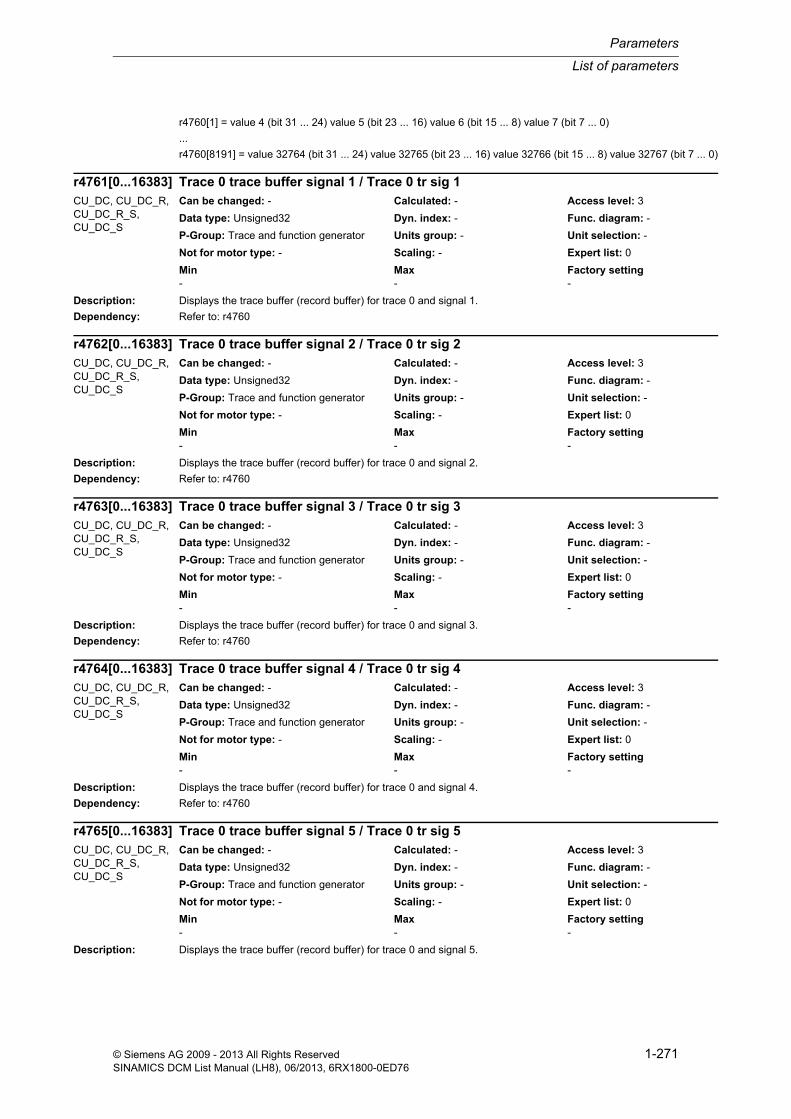
List of parameters
Parameters
1-271© Siemens AG 2009 - 2013 All Rights ReservedSINAMICS DCM List Manual (LH8), 06/2013, 6RX1800-0ED76
r4760[1] = value 4 (bit 31 ... 24) value 5 (bit 23 ... 16) value 6 (bit 15 ... 8) value 7 (bit 7 ... 0)
...
r4760[8191] = value 32764 (bit 31 ... 24) value 32765 (bit 23 ... 16) value 32766 (bit 15 ... 8) value 32767 (bit 7 ... 0)
Description: Displays the trace buffer (record buffer) for trace 0 and signal 1.
Dependency: Refer to: r4760
Description: Displays the trace buffer (record buffer) for trace 0 and signal 2.
Dependency: Refer to: r4760
Description: Displays the trace buffer (record buffer) for trace 0 and signal 3.
Dependency: Refer to: r4760
Description: Displays the trace buffer (record buffer) for trace 0 and signal 4.
Dependency: Refer to: r4760
Description: Displays the trace buffer (record buffer) for trace 0 and signal 5.
r4761[0...16383] Trace 0 trace buffer signal 1 / Trace 0 tr sig 1CU_DC, CU_DC_R, CU_DC_R_S, CU_DC_S
Can be changed: - Calculated: - Access level: 3
Data type: Unsigned32 Dyn. index: - Func. diagram: -
P-Group: Trace and function generator Units group: - Unit selection: -
Not for motor type: - Scaling: - Expert list: 0
Min Max Factory setting - - -
r4762[0...16383] Trace 0 trace buffer signal 2 / Trace 0 tr sig 2CU_DC, CU_DC_R, CU_DC_R_S, CU_DC_S
Can be changed: - Calculated: - Access level: 3
Data type: Unsigned32 Dyn. index: - Func. diagram: -
P-Group: Trace and function generator Units group: - Unit selection: -
Not for motor type: - Scaling: - Expert list: 0
Min Max Factory setting - - -
r4763[0...16383] Trace 0 trace buffer signal 3 / Trace 0 tr sig 3CU_DC, CU_DC_R, CU_DC_R_S, CU_DC_S
Can be changed: - Calculated: - Access level: 3
Data type: Unsigned32 Dyn. index: - Func. diagram: -
P-Group: Trace and function generator Units group: - Unit selection: -
Not for motor type: - Scaling: - Expert list: 0
Min Max Factory setting - - -
r4764[0...16383] Trace 0 trace buffer signal 4 / Trace 0 tr sig 4CU_DC, CU_DC_R, CU_DC_R_S, CU_DC_S
Can be changed: - Calculated: - Access level: 3
Data type: Unsigned32 Dyn. index: - Func. diagram: -
P-Group: Trace and function generator Units group: - Unit selection: -
Not for motor type: - Scaling: - Expert list: 0
Min Max Factory setting - - -
r4765[0...16383] Trace 0 trace buffer signal 5 / Trace 0 tr sig 5CU_DC, CU_DC_R, CU_DC_R_S, CU_DC_S
Can be changed: - Calculated: - Access level: 3
Data type: Unsigned32 Dyn. index: - Func. diagram: -
P-Group: Trace and function generator Units group: - Unit selection: -
Not for motor type: - Scaling: - Expert list: 0
Min Max Factory setting - - -

Parameters
List of parameters
1-272 © Siemens AG 2009 - 2013 All Rights ReservedSINAMICS DCM List Manual (LH8), 06/2013, 6RX1800-0ED76
Dependency: Refer to: r4760
Description: Displays the trace buffer (record buffer) for trace 0 and signal 6.
Dependency: Refer to: r4760
Description: Displays the trace buffer (record buffer) for trace 0 and signal 7.
Dependency: Refer to: r4760
Description: Displays the trace buffer (record buffer) for trace 1 and signal 0.
Dependency: Refer to: r4760
Description: Displays the trace buffer (record buffer) for trace 1 and signal 1.
Dependency: Refer to: r4760
Description: Displays the trace buffer (record buffer) for trace 1 and signal 2.
Dependency: Refer to: r4760
r4766[0...16383] Trace 0 trace buffer signal 6 / Trace 0 tr sig 6CU_DC, CU_DC_R, CU_DC_R_S, CU_DC_S
Can be changed: - Calculated: - Access level: 3
Data type: Unsigned32 Dyn. index: - Func. diagram: -
P-Group: Trace and function generator Units group: - Unit selection: -
Not for motor type: - Scaling: - Expert list: 0
Min Max Factory setting - - -
r4767[0...16383] Trace 0 trace buffer signal 7 / Trace 0 tr sig 7CU_DC, CU_DC_R, CU_DC_R_S, CU_DC_S
Can be changed: - Calculated: - Access level: 3
Data type: Unsigned32 Dyn. index: - Func. diagram: -
P-Group: Trace and function generator Units group: - Unit selection: -
Not for motor type: - Scaling: - Expert list: 0
Min Max Factory setting - - -
r4770[0...16383] Trace 1 trace buffer signal 0 / Trace 1 trace sig0CU_DC, CU_DC_R, CU_DC_R_S, CU_DC_S
Can be changed: - Calculated: - Access level: 3
Data type: Unsigned32 Dyn. index: - Func. diagram: -
P-Group: Trace and function generator Units group: - Unit selection: -
Not for motor type: - Scaling: - Expert list: 0
Min Max Factory setting - - -
r4771[0...16383] Trace 1 trace buffer signal 1 / Trace 1 tr sig 1CU_DC, CU_DC_R, CU_DC_R_S, CU_DC_S
Can be changed: - Calculated: - Access level: 3
Data type: Unsigned32 Dyn. index: - Func. diagram: -
P-Group: Trace and function generator Units group: - Unit selection: -
Not for motor type: - Scaling: - Expert list: 0
Min Max Factory setting - - -
r4772[0...16383] Trace 1 trace buffer signal 2 / Trace 1 tr sig 2CU_DC, CU_DC_R, CU_DC_R_S, CU_DC_S
Can be changed: - Calculated: - Access level: 3
Data type: Unsigned32 Dyn. index: - Func. diagram: -
P-Group: Trace and function generator Units group: - Unit selection: -
Not for motor type: - Scaling: - Expert list: 0
Min Max Factory setting - - -

List of parameters
Parameters
1-273© Siemens AG 2009 - 2013 All Rights ReservedSINAMICS DCM List Manual (LH8), 06/2013, 6RX1800-0ED76
Description: Displays the trace buffer (record buffer) for trace 1 and signal 3.
Dependency: Refer to: r4760
Description: Displays the trace buffer (record buffer) for trace 1 and signal 4.
Dependency: Refer to: r4760
Description: Displays the trace buffer (record buffer) for trace 1 and signal 5.
Dependency: Refer to: r4760
Description: Displays the trace buffer (record buffer) for trace 1 and signal 6.
Dependency: Refer to: r4760
Description: Displays the trace buffer (record buffer) for trace 1 and signal 7.
Dependency: Refer to: r4760
r4773[0...16383] Trace 1 trace buffer signal 3 / Trace 1 tr sig 3CU_DC, CU_DC_R, CU_DC_R_S, CU_DC_S
Can be changed: - Calculated: - Access level: 3
Data type: Unsigned32 Dyn. index: - Func. diagram: -
P-Group: Trace and function generator Units group: - Unit selection: -
Not for motor type: - Scaling: - Expert list: 0
Min Max Factory setting - - -
r4774[0...16383] Trace 1 trace buffer signal 4 / Trace 1 tr sig 4CU_DC, CU_DC_R, CU_DC_R_S, CU_DC_S
Can be changed: - Calculated: - Access level: 3
Data type: Unsigned32 Dyn. index: - Func. diagram: -
P-Group: Trace and function generator Units group: - Unit selection: -
Not for motor type: - Scaling: - Expert list: 0
Min Max Factory setting - - -
r4775[0...16383] Trace 1 trace buffer signal 5 / Trace 1 tr sig 5CU_DC, CU_DC_R, CU_DC_R_S, CU_DC_S
Can be changed: - Calculated: - Access level: 3
Data type: Unsigned32 Dyn. index: - Func. diagram: -
P-Group: Trace and function generator Units group: - Unit selection: -
Not for motor type: - Scaling: - Expert list: 0
Min Max Factory setting - - -
r4776[0...16383] Trace 1 trace buffer signal 6 / Trace 1 tr sig 6CU_DC, CU_DC_R, CU_DC_R_S, CU_DC_S
Can be changed: - Calculated: - Access level: 3
Data type: Unsigned32 Dyn. index: - Func. diagram: -
P-Group: Trace and function generator Units group: - Unit selection: -
Not for motor type: - Scaling: - Expert list: 0
Min Max Factory setting - - -
r4777[0...16383] Trace 1 trace buffer signal 7 / Trace 1 tr sig 7CU_DC, CU_DC_R, CU_DC_R_S, CU_DC_S
Can be changed: - Calculated: - Access level: 3
Data type: Unsigned32 Dyn. index: - Func. diagram: -
P-Group: Trace and function generator Units group: - Unit selection: -
Not for motor type: - Scaling: - Expert list: 0
Min Max Factory setting - - -

Parameters
List of parameters
1-274 © Siemens AG 2009 - 2013 All Rights ReservedSINAMICS DCM List Manual (LH8), 06/2013, 6RX1800-0ED76
Description: Sets the physical address for the first signal to be traced.
The data type is defined using p4730.
Index: [0] = Trace 0[1] = Trace 1
Description: Sets the physical address for the second signal to be traced.
The data type is defined using p4731.
Index: [0] = Trace 0[1] = Trace 1
Description: Sets the physical address for the third signal to be traced.
The data type is defined using p4732.
Index: [0] = Trace 0[1] = Trace 1
Description: Sets the physical address for the fourth signal to be traced.
The data type is defined using p4733.
Index: [0] = Trace 0[1] = Trace 1
p4780[0...1] Trace physical address signal 0 / Trace PhyAddr Sig0CU_DC, CU_DC_R, CU_DC_R_S, CU_DC_S
Can be changed: U, T Calculated: - Access level: 3
Data type: Unsigned32 Dyn. index: - Func. diagram: -
P-Group: Trace and function generator Units group: - Unit selection: -
Not for motor type: - Scaling: - Expert list: 0
Min Max Factory setting 0000 bin 1111 1111 1111 1111 1111 1111
1111 1111 bin 0000 bin
p4781[0...1] Trace physical address signal 1 / Trace PhyAddr Sig1CU_DC, CU_DC_R, CU_DC_R_S, CU_DC_S
Can be changed: U, T Calculated: - Access level: 3
Data type: Unsigned32 Dyn. index: - Func. diagram: -
P-Group: Trace and function generator Units group: - Unit selection: -
Not for motor type: - Scaling: - Expert list: 0
Min Max Factory setting 0000 bin 1111 1111 1111 1111 1111 1111
1111 1111 bin 0000 bin
p4782[0...1] Trace physical address signal 2 / Trace PhyAddr Sig2CU_DC, CU_DC_R, CU_DC_R_S, CU_DC_S
Can be changed: U, T Calculated: - Access level: 3
Data type: Unsigned32 Dyn. index: - Func. diagram: -
P-Group: Trace and function generator Units group: - Unit selection: -
Not for motor type: - Scaling: - Expert list: 0
Min Max Factory setting 0000 bin 1111 1111 1111 1111 1111 1111
1111 1111 bin 0000 bin
p4783[0...1] Trace physical address signal 3 / Trace PhyAddr Sig3CU_DC, CU_DC_R, CU_DC_R_S, CU_DC_S
Can be changed: U, T Calculated: - Access level: 3
Data type: Unsigned32 Dyn. index: - Func. diagram: -
P-Group: Trace and function generator Units group: - Unit selection: -
Not for motor type: - Scaling: - Expert list: 0
Min Max Factory setting 0000 bin 1111 1111 1111 1111 1111 1111
1111 1111 bin 0000 bin

List of parameters
Parameters
1-275© Siemens AG 2009 - 2013 All Rights ReservedSINAMICS DCM List Manual (LH8), 06/2013, 6RX1800-0ED76
Description: Sets the physical address for the fifth signal to be traced.
The data type is defined using p4734.
Index: [0] = Trace 0[1] = Trace 1
Description: Sets the physical address for the sixth signal to be traced.
The data type is defined using p4735.
Index: [0] = Trace 0[1] = Trace 1
Description: Sets the physical address for the seventh signal to be traced.
The data type is defined using p4736.
Index: [0] = Trace 0[1] = Trace 1
Description: Sets the physical address for the eighth signal to be traced.
The data type is defined using p4737.
Index: [0] = Trace 0[1] = Trace 1
p4784[0...1] Trace physical address signal 4 / Trace PhyAddr Sig4CU_DC, CU_DC_R, CU_DC_R_S, CU_DC_S
Can be changed: U, T Calculated: - Access level: 3
Data type: Unsigned32 Dyn. index: - Func. diagram: -
P-Group: Trace and function generator Units group: - Unit selection: -
Not for motor type: - Scaling: - Expert list: 0
Min Max Factory setting 0000 bin 1111 1111 1111 1111 1111 1111
1111 1111 bin 0000 bin
p4785[0...1] Trace physical address signal 5 / Trace PhyAddr Sig5CU_DC, CU_DC_R, CU_DC_R_S, CU_DC_S
Can be changed: U, T Calculated: - Access level: 3
Data type: Unsigned32 Dyn. index: - Func. diagram: -
P-Group: Trace and function generator Units group: - Unit selection: -
Not for motor type: - Scaling: - Expert list: 0
Min Max Factory setting 0000 bin 1111 1111 1111 1111 1111 1111
1111 1111 bin 0000 bin
p4786[0...1] Trace physical address signal 6 / Trace PhyAddr Sig6CU_DC, CU_DC_R, CU_DC_R_S, CU_DC_S
Can be changed: U, T Calculated: - Access level: 3
Data type: Unsigned32 Dyn. index: - Func. diagram: -
P-Group: Trace and function generator Units group: - Unit selection: -
Not for motor type: - Scaling: - Expert list: 0
Min Max Factory setting 0000 bin 1111 1111 1111 1111 1111 1111
1111 1111 bin 0000 bin
p4787[0...1] Trace physical address signal 7 / Trace PhyAddr Sig7CU_DC, CU_DC_R, CU_DC_R_S, CU_DC_S
Can be changed: U, T Calculated: - Access level: 3
Data type: Unsigned32 Dyn. index: - Func. diagram: -
P-Group: Trace and function generator Units group: - Unit selection: -
Not for motor type: - Scaling: - Expert list: 0
Min Max Factory setting 0000 bin 1111 1111 1111 1111 1111 1111
1111 1111 bin 0000 bin

Parameters
List of parameters
1-276 © Siemens AG 2009 - 2013 All Rights ReservedSINAMICS DCM List Manual (LH8), 06/2013, 6RX1800-0ED76
Description: Sets the physical address for the trigger signal.
The data type is defined by making the appropriate selection in p4711.
Index: [0] = Trace 0[1] = Trace 1
Description: Displays the recorded data type 5 for the trace.
Index: [0] = Trace 0[1] = Trace 1
Description: Displays the recorded data type 6 for the trace.
Index: [0] = Trace 0[1] = Trace 1
Description: Displays the recorded data type 7 for the trace.
Index: [0] = Trace 0[1] = Trace 1
Description: Displays the recorded data type 8 for the trace.
p4789[0...1] Trace physical address trigger signal / Trace PhyAddr TrigCU_DC, CU_DC_R, CU_DC_R_S, CU_DC_S
Can be changed: U, T Calculated: - Access level: 3
Data type: Unsigned32 Dyn. index: - Func. diagram: -
P-Group: Trace and function generator Units group: - Unit selection: -
Not for motor type: - Scaling: - Expert list: 0
Min Max Factory setting 0000 hex FFFF FFFF hex 0000 hex
r4790[0...1] Trace data type 5 traced / Trace rec type 5CU_DC, CU_DC_R, CU_DC_R_S, CU_DC_S
Can be changed: - Calculated: - Access level: 3
Data type: Unsigned32 Dyn. index: - Func. diagram: -
P-Group: Trace and function generator Units group: - Unit selection: -
Not for motor type: - Scaling: - Expert list: 0
Min Max Factory setting - - -
r4791[0...1] Trace data type 6 traced / Trace rec type 6CU_DC, CU_DC_R, CU_DC_R_S, CU_DC_S
Can be changed: - Calculated: - Access level: 3
Data type: Unsigned32 Dyn. index: - Func. diagram: -
P-Group: Trace and function generator Units group: - Unit selection: -
Not for motor type: - Scaling: - Expert list: 0
Min Max Factory setting - - -
r4792[0...1] Trace data type 7 traced / Trace rec type 7CU_DC, CU_DC_R, CU_DC_R_S, CU_DC_S
Can be changed: - Calculated: - Access level: 3
Data type: Unsigned32 Dyn. index: - Func. diagram: -
P-Group: Trace and function generator Units group: - Unit selection: -
Not for motor type: - Scaling: - Expert list: 0
Min Max Factory setting - - -
r4793[0...1] Trace data type 8 traced / Trace rec type 8CU_DC, CU_DC_R, CU_DC_R_S, CU_DC_S
Can be changed: - Calculated: - Access level: 3
Data type: Unsigned32 Dyn. index: - Func. diagram: -
P-Group: Trace and function generator Units group: - Unit selection: -
Not for motor type: - Scaling: - Expert list: 0
Min Max Factory setting - - -

List of parameters
Parameters
1-277© Siemens AG 2009 - 2013 All Rights ReservedSINAMICS DCM List Manual (LH8), 06/2013, 6RX1800-0ED76
Index: [0] = Trace 0[1] = Trace 1
Description: Changes over the memory bank to read out the contents of the trace buffer.
Dependency: Refer to: r4740, r4741, r4742, r4743, r4750, r4751, r4752, r4753
Description: Displays the instant in time for fulfilling the trigger condition for trace recorder 0.
The time comprises milliseconds (index 0) and days (index 1).
Index: [0] = Milliseconds[1] = Days
Dependency: Refer to: r2114, r3102, r4719
Notice: The accuracy of the trigger instant depends on the accuracy of the underlying basis time.
For clarification:
The trigger instant is calculated with a µs accuracy. If the underlying basis time is only available with ms accuracy, then as a result of rounding effects, an inaccuracy of 1 ms can occur.
When referred to r4719, the trigger instant can therefore deviate somewhat.
Note: If the time calculation of the drive can be synchronized with a higher-level control, then this time can be taken from the actual UTC time (r3102 ). Otherwise, the time is based on the system runtime (r2114).
Description: Displays the instant in time for fulfilling the trigger condition for trace recorder 1.
The time comprises milliseconds (index 0) and days (index 1).
Index: [0] = Milliseconds[1] = Days
Dependency: Refer to: r2114, r3102, r4719
Notice: The accuracy of the trigger instant depends on the accuracy of the underlying basis time.
For clarification:
The trigger instant is calculated with a µs accuracy. If the underlying basis time is only available with ms accuracy, then as a result of rounding effects, an inaccuracy of 1 ms can occur.
When referred to r4719, the trigger instant can therefore deviate somewhat.
Note: If the time calculation of the drive can be synchronized with a higher-level control, then this time can be taken from the actual UTC time (r3102 ). Otherwise, the time is based on the system runtime (r2114).
p4795 Trace memory bank changeover / Trace mem changeovCU_DC, CU_DC_R, CU_DC_R_S, CU_DC_S
Can be changed: U, T Calculated: - Access level: 3
Data type: Unsigned32 Dyn. index: - Func. diagram: -
P-Group: Trace and function generator Units group: - Unit selection: -
Not for motor type: - Scaling: - Expert list: 0
Min Max Factory setting 0 500 0
r4797[0...1] Trace 0 trigger instant / Trace 0 t_triggerCU_DC, CU_DC_R, CU_DC_R_S, CU_DC_S
Can be changed: - Calculated: - Access level: 3
Data type: Unsigned32 Dyn. index: - Func. diagram: -
P-Group: Trace and function generator Units group: - Unit selection: -
Not for motor type: - Scaling: - Expert list: 0
Min Max Factory setting - - -
r4798[0...1] Trace 1 trigger instant / Trace 1 t_triggerCU_DC, CU_DC_R, CU_DC_R_S, CU_DC_S
Can be changed: - Calculated: - Access level: 3
Data type: Unsigned32 Dyn. index: - Func. diagram: -
P-Group: Trace and function generator Units group: - Unit selection: -
Not for motor type: - Scaling: - Expert list: 0
Min Max Factory setting - - -

Parameters
List of parameters
1-278 © Siemens AG 2009 - 2013 All Rights ReservedSINAMICS DCM List Manual (LH8), 06/2013, 6RX1800-0ED76
Description: Displays the free memory for the trace in bytes.
Dependency: Refer to: r4708
Description: The function generator is started with p4800 = 1.
The signal is only generated for a 1 signal of binector input p4819.
Value: 0: Stop function generator1: Start function generator2: Check function generator parameterization3: Start function generator without enable signals
Dependency: Refer to: p4819
Description: Displays the actual status of the function generator.
Value: 0: Inactive1: Generate accelerating ramp to offset2: Generate parameterized signal shape3: Generate braking ramp4: Function generator stopped due to missing enable signals5: Function generator waits for BI: p48196: Function generator parameterization has been checked
Dependency: Refer to: p4800, p4819
Description: Displays the status of the function generator.
0 signal: Function generator inactive
1 signal: Function generator running
r4799 Trace memory location free / Trace mem freeCU_DC, CU_DC_R, CU_DC_R_S, CU_DC_S
Can be changed: - Calculated: - Access level: 3
Data type: Unsigned32 Dyn. index: - Func. diagram: -
P-Group: Trace and function generator Units group: - Unit selection: -
Not for motor type: - Scaling: - Expert list: 0
Min Max Factory setting - - -
p4800 Function generator control / FG controlCU_DC, CU_DC_R, CU_DC_R_S, CU_DC_S
Can be changed: U, T Calculated: - Access level: 3
Data type: Integer16 Dyn. index: - Func. diagram: -
P-Group: Trace and function generator Units group: - Unit selection: -
Not for motor type: - Scaling: - Expert list: 0
Min Max Factory setting 0 3 0
r4805 Function generator status / FG statusCU_DC, CU_DC_R, CU_DC_R_S, CU_DC_S
Can be changed: - Calculated: - Access level: 3
Data type: Integer16 Dyn. index: - Func. diagram: -
P-Group: Trace and function generator Units group: - Unit selection: -
Not for motor type: - Scaling: - Expert list: 0
Min Max Factory setting 0 6 -
r4806.0 BO: Function generator status signal / FG status signalCU_DC, CU_DC_R, CU_DC_R_S, CU_DC_S
Can be changed: - Calculated: - Access level: 3
Data type: Unsigned32 Dyn. index: - Func. diagram: -
P-Group: Trace and function generator Units group: - Unit selection: -
Not for motor type: - Scaling: - Expert list: 0
Min Max Factory setting - - -

List of parameters
Parameters
1-279© Siemens AG 2009 - 2013 All Rights ReservedSINAMICS DCM List Manual (LH8), 06/2013, 6RX1800-0ED76
Description: Sets the operating mode of the function generator.
Value: 0: Connection at connector output r48181: Connection at current setpoint after filter and r48182: Connection as disturbing torque and r48183: Connection at speed setpoint after filter and r48184: Connection at current setpoint before filter and r48185: Connection at speed setpoint before filter and r48186: Connection for free measurement function r4818 and r483499: Connection at physical address and r4818
Description: Sets the physical address where the function generator is to be connected.
Dependency: Only effective when p4810 = 99.
Description: Sets the reference value for 100 % for referred inputs.
Dependency: Only effective when p4810 = 99.
Description: Sets the scaling for the integer number of the output signal for the function generator.
Dependency: Refer to: r4805, r4817
Note: The parameter can only be changed in the following operating states:
r4805 = 0, 4, 6
Bit field: Bit Signal name 1 signal 0 signal FP00 Bit 0 ON OFF -
p4810 Function generator mode / FG operating modeCU_DC, CU_DC_R, CU_DC_R_S, CU_DC_S
Can be changed: U, T Calculated: - Access level: 3
Data type: Integer16 Dyn. index: - Func. diagram: -
P-Group: Trace and function generator Units group: - Unit selection: -
Not for motor type: - Scaling: - Expert list: 0
Min Max Factory setting 0 99 0
p4812 Function generator physical address / FG phys addressCU_DC, CU_DC_R, CU_DC_R_S, CU_DC_S
Can be changed: U, T Calculated: - Access level: 3
Data type: Unsigned32 Dyn. index: - Func. diagram: -
P-Group: Trace and function generator Units group: - Unit selection: -
Not for motor type: - Scaling: - Expert list: 0
Min Max Factory setting 0 4294967295 0
p4813 Function generator physical address reference value / FG phys addr refCU_DC, CU_DC_R, CU_DC_R_S, CU_DC_S
Can be changed: U, T Calculated: - Access level: 3
Data type: FloatingPoint32 Dyn. index: - Func. diagram: -
P-Group: Trace and function generator Units group: - Unit selection: -
Not for motor type: - Scaling: - Expert list: 0
Min Max Factory setting 1.00 1000000.00 1.00
p4816 Function generator output signal integer number scaling / FG outp integ scalCU_DC, CU_DC_R, CU_DC_R_S, CU_DC_S
Can be changed: U, T Calculated: - Access level: 4
Data type: Integer32 Dyn. index: - Func. diagram: -
P-Group: - Units group: - Unit selection: -
Not for motor type: - Scaling: - Expert list: 1
Min Max Factory setting -2147483648 2147483647 0

Parameters
List of parameters
1-280 © Siemens AG 2009 - 2013 All Rights ReservedSINAMICS DCM List Manual (LH8), 06/2013, 6RX1800-0ED76
Description: Display and connector output for the integer number of the output signal for the function generator.
Dependency: Refer to: p4816
Note: The value is output independent of the function generator operating mode.
Description: Displays the output signal for the function generator.
Dependency: Refer to: p4810
Note: The value is displayed independently of the function generator mode.
Description: Sets the signal source to control the function generator.
When the function generator is running, signal generation is stopped with a 0 signal from BI: p4819 and p4800 is set to 0.
Dependency: Refer to: p4800
Description: Sets the signal to be generated for the function generator.
Value: 1: Square-wave2: Staircase3: Delta4: Binary noise - PRBS (Pseudo Random Binary Signal)5: Sine-wave
r4817 CO: Function generator output signal integer number / FG outp integ no.CU_DC, CU_DC_R, CU_DC_R_S, CU_DC_S
Can be changed: - Calculated: - Access level: 4
Data type: Integer32 Dyn. index: - Func. diagram: -
P-Group: Trace and function generator Units group: - Unit selection: -
Not for motor type: - Scaling: - Expert list: 0
Min Max Factory setting - - -
r4818 CO: Function generator output signal / FG outp_sigCU_DC, CU_DC_R, CU_DC_R_S, CU_DC_S
Can be changed: - Calculated: - Access level: 3
Data type: FloatingPoint32 Dyn. index: - Func. diagram: -
P-Group: Trace and function generator Units group: - Unit selection: -
Not for motor type: - Scaling: PERCENT Expert list: 0
Min Max Factory setting - [%] - [%] - [%]
p4819 BI: Function generator control / FG controlCU_DC, CU_DC_R, CU_DC_R_S, CU_DC_S
Can be changed: U, T Calculated: - Access level: 3
Data type: Unsigned32 / Binary Dyn. index: - Func. diagram: -
P-Group: Trace and function generator Units group: - Unit selection: -
Not for motor type: - Scaling: - Expert list: 0
Min Max Factory setting - - 1
p4820 Function generator signal shape / FG signal shapeCU_DC, CU_DC_R, CU_DC_R_S, CU_DC_S
Can be changed: U, T Calculated: - Access level: 3
Data type: Integer16 Dyn. index: - Func. diagram: -
P-Group: Trace and function generator Units group: - Unit selection: -
Not for motor type: - Scaling: - Expert list: 0
Min Max Factory setting 1 5 1

List of parameters
Parameters
1-281© Siemens AG 2009 - 2013 All Rights ReservedSINAMICS DCM List Manual (LH8), 06/2013, 6RX1800-0ED76
Description: Sets the period of the signal to be generated for the function generator.
Dependency: Ineffective when p4820 = 4 (PRBS).
Description: Sets the pulse width for the signal to be generated for the function generator.
Dependency: Only effective when p4820 = 1 (square-wave).
Description: Sets the bandwidth for the signal to be generated for the function generator.
Dependency: Only effective when p4820 = 4 (PRBS).
Refer to: p4830
Description: Sets the amplitude for the signal to be generated for the function generator.
Dependency: Units are dependent on p4810.
If p4810 = 1, 2, 4: The amplitude is referred to p2002 (reference current).
If p4810 = 3, 5: The amplitude is referred to p2000 (reference speed).
Description: Sets the second amplitude for the signal to be generated for the function generator.
p4821 Function generator period / FG period durationCU_DC, CU_DC_R, CU_DC_R_S, CU_DC_S
Can be changed: U, T Calculated: - Access level: 3
Data type: FloatingPoint32 Dyn. index: - Func. diagram: -
P-Group: Trace and function generator Units group: - Unit selection: -
Not for motor type: - Scaling: - Expert list: 0
Min Max Factory setting 0.00 [ms] 60000.00 [ms] 1000.00 [ms]
p4822 Function generator pulse width / FG pulse widthCU_DC, CU_DC_R, CU_DC_R_S, CU_DC_S
Can be changed: U, T Calculated: - Access level: 3
Data type: FloatingPoint32 Dyn. index: - Func. diagram: -
P-Group: Trace and function generator Units group: - Unit selection: -
Not for motor type: - Scaling: - Expert list: 0
Min Max Factory setting 0.00 [ms] 60000.00 [ms] 500.00 [ms]
p4823 Function generator bandwidth / FG bandwidthCU_DC, CU_DC_R, CU_DC_R_S, CU_DC_S
Can be changed: U, T Calculated: - Access level: 3
Data type: FloatingPoint32 Dyn. index: - Func. diagram: -
P-Group: Trace and function generator Units group: - Unit selection: -
Not for motor type: - Scaling: - Expert list: 0
Min Max Factory setting 0.0025 [Hz] 16000.0000 [Hz] 4000.0000 [Hz]
p4824 Function generator amplitude / FG amplitudeCU_DC, CU_DC_R, CU_DC_R_S, CU_DC_S
Can be changed: U, T Calculated: - Access level: 3
Data type: FloatingPoint32 Dyn. index: - Func. diagram: -
P-Group: Trace and function generator Units group: - Unit selection: -
Not for motor type: - Scaling: - Expert list: 0
Min Max Factory setting -1600.00 [%] 1600.00 [%] 5.00 [%]
p4825 Function generator 2nd amplitude / FG 2nd amplitudeCU_DC, CU_DC_R, CU_DC_R_S, CU_DC_S
Can be changed: U, T Calculated: - Access level: 3
Data type: FloatingPoint32 Dyn. index: - Func. diagram: -
P-Group: Trace and function generator Units group: - Unit selection: -
Not for motor type: - Scaling: - Expert list: 0
Min Max Factory setting -1600.00 [%] 1600.00 [%] 7.00 [%]

Parameters
List of parameters
1-282 © Siemens AG 2009 - 2013 All Rights ReservedSINAMICS DCM List Manual (LH8), 06/2013, 6RX1800-0ED76
Dependency: Only effective for p4820 = 2 (staircase).
Units are dependent on p4810.
If p4810 = 1, 2, 4: The amplitude is referred to p2002 (reference current).
If p4810 = 3, 5: The amplitude is referred to p2000 (reference speed).
Description: Sets the offset (DC component) of the signal to be generated for the function generator.
Dependency: Units are dependent on p4810.
If p4810 = 1, 2, 4: The offset is referred to p2002 (reference current).
If p4810 = 3, 5: The offset is referred to p2000 (reference speed).
If p4810 = 2: In order to avoid the undesirable effects of play (backlash), the offset does not act on the current set-point, but instead on the speed setpoint.
Description: Sets the ramp-up time to the offset for the function generator.
Description: Sets the lower limit for the function generator.
Dependency: For p4810 = 2 the limit only applies to the current setpoint, but not the speed setpoint (offset).
Description: Sets the upper limit for the function generator.
Dependency: For p4810 = 2 the limit only applies to the current setpoint, but not the speed setpoint (offset).
p4826 Function generator offset / FG offsetCU_DC, CU_DC_R, CU_DC_R_S, CU_DC_S
Can be changed: U, T Calculated: - Access level: 3
Data type: FloatingPoint32 Dyn. index: - Func. diagram: -
P-Group: Trace and function generator Units group: - Unit selection: -
Not for motor type: - Scaling: - Expert list: 0
Min Max Factory setting -1600.00 [%] 1600.00 [%] 0.00 [%]
p4827 Function generator ramp-up time to offset / FG ramp-up offsetCU_DC, CU_DC_R, CU_DC_R_S, CU_DC_S
Can be changed: U, T Calculated: - Access level: 3
Data type: FloatingPoint32 Dyn. index: - Func. diagram: -
P-Group: Trace and function generator Units group: - Unit selection: -
Not for motor type: - Scaling: - Expert list: 0
Min Max Factory setting 0.00 [ms] 100000.00 [ms] 32.00 [ms]
p4828 Function generator lower limit / FG lower limitCU_DC, CU_DC_R, CU_DC_R_S, CU_DC_S
Can be changed: U, T Calculated: - Access level: 3
Data type: FloatingPoint32 Dyn. index: - Func. diagram: -
P-Group: Trace and function generator Units group: - Unit selection: -
Not for motor type: - Scaling: - Expert list: 0
Min Max Factory setting -10000.00 [%] 0.00 [%] -100.00 [%]
p4829 Function generator upper limit / FG upper limitCU_DC, CU_DC_R, CU_DC_R_S, CU_DC_S
Can be changed: U, T Calculated: - Access level: 3
Data type: FloatingPoint32 Dyn. index: - Func. diagram: -
P-Group: Trace and function generator Units group: - Unit selection: -
Not for motor type: - Scaling: - Expert list: 0
Min Max Factory setting 0.00 [%] 10000.00 [%] 100.00 [%]
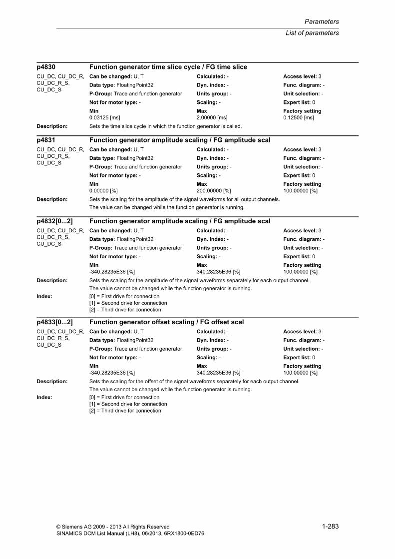
List of parameters
Parameters
1-283© Siemens AG 2009 - 2013 All Rights ReservedSINAMICS DCM List Manual (LH8), 06/2013, 6RX1800-0ED76
Description: Sets the time slice cycle in which the function generator is called.
Description: Sets the scaling for the amplitude of the signal waveforms for all output channels.
The value can be changed while the function generator is running.
Description: Sets the scaling for the amplitude of the signal waveforms separately for each output channel.
The value cannot be changed while the function generator is running.
Index: [0] = First drive for connection[1] = Second drive for connection[2] = Third drive for connection
Description: Sets the scaling for the offset of the signal waveforms separately for each output channel.
The value cannot be changed while the function generator is running.
Index: [0] = First drive for connection[1] = Second drive for connection[2] = Third drive for connection
p4830 Function generator time slice cycle / FG time sliceCU_DC, CU_DC_R, CU_DC_R_S, CU_DC_S
Can be changed: U, T Calculated: - Access level: 3
Data type: FloatingPoint32 Dyn. index: - Func. diagram: -
P-Group: Trace and function generator Units group: - Unit selection: -
Not for motor type: - Scaling: - Expert list: 0
Min Max Factory setting 0.03125 [ms] 2.00000 [ms] 0.12500 [ms]
p4831 Function generator amplitude scaling / FG amplitude scalCU_DC, CU_DC_R, CU_DC_R_S, CU_DC_S
Can be changed: U, T Calculated: - Access level: 3
Data type: FloatingPoint32 Dyn. index: - Func. diagram: -
P-Group: Trace and function generator Units group: - Unit selection: -
Not for motor type: - Scaling: - Expert list: 0
Min Max Factory setting 0.00000 [%] 200.00000 [%] 100.00000 [%]
p4832[0...2] Function generator amplitude scaling / FG amplitude scalCU_DC, CU_DC_R, CU_DC_R_S, CU_DC_S
Can be changed: U, T Calculated: - Access level: 3
Data type: FloatingPoint32 Dyn. index: - Func. diagram: -
P-Group: Trace and function generator Units group: - Unit selection: -
Not for motor type: - Scaling: - Expert list: 0
Min Max Factory setting -340.28235E36 [%] 340.28235E36 [%] 100.00000 [%]
p4833[0...2] Function generator offset scaling / FG offset scalCU_DC, CU_DC_R, CU_DC_R_S, CU_DC_S
Can be changed: U, T Calculated: - Access level: 3
Data type: FloatingPoint32 Dyn. index: - Func. diagram: -
P-Group: Trace and function generator Units group: - Unit selection: -
Not for motor type: - Scaling: - Expert list: 0
Min Max Factory setting -340.28235E36 [%] 340.28235E36 [%] 100.00000 [%]

Parameters
List of parameters
1-284 © Siemens AG 2009 - 2013 All Rights ReservedSINAMICS DCM List Manual (LH8), 06/2013, 6RX1800-0ED76
Description: Displays the output signal for the free measurement function.
Index: [0] = Signal 1[1] = Signal 2[2] = Signal 3[3] = Signal 4[4] = Signal 5
Dependency: Refer to: p4810
Note: The signals are only output in the "free measurement function" operating mode (p4810 = 6)
Description: Sets the scaling of the output signals for the free measurement function.
Index: [0] = Signal 1[1] = Signal 2[2] = Signal 3[3] = Signal 4[4] = Signal 5
Note: The parameter cannot be changed when the measurement function has been started (r4706 = 2, 3).
Description: Sets the number of cycles of a multiple trace.
The multiple trace is de-activated with a value = 0.
Index: [0] = Trace 0[1] = Trace 1
Dependency: Refer to: r4841, p4844
Notice: A multiple trace can have a negative impact on the total system performance.
From their inherent principle of operation, flash memory cards are subject to wear as a result of write operations. As a consequence, the lifetime of flash memory cards is reduced when using the multiple trace functionality.
r4834[0...4] CO: Function generator free measurement output signal / FG fr MeasFct outpCU_DC, CU_DC_R, CU_DC_R_S, CU_DC_S
Can be changed: - Calculated: - Access level: 3
Data type: FloatingPoint32 Dyn. index: - Func. diagram: -
P-Group: Trace and function generator Units group: - Unit selection: -
Not for motor type: - Scaling: PERCENT Expert list: 0
Min Max Factory setting - [%] - [%] - [%]
p4835[0...4] Function generator free measurement function scaling / FG fr MeasFct scalCU_DC, CU_DC_R, CU_DC_R_S, CU_DC_S
Can be changed: U, T Calculated: - Access level: 3
Data type: FloatingPoint32 Dyn. index: - Func. diagram: -
P-Group: - Units group: - Unit selection: -
Not for motor type: - Scaling: - Expert list: 1
Min Max Factory setting -200.00000 [%] 200.00000 [%] 100.00000 [%]
p4840[0...1] MTrace cycle number setting / Cycle numberCU_DC, CU_DC_R, CU_DC_R_S, CU_DC_S
Can be changed: U, T Calculated: - Access level: 3
Data type: Unsigned32 Dyn. index: - Func. diagram: -
P-Group: Trace and function generator Units group: - Unit selection: -
Not for motor type: - Scaling: - Expert list: 0
Min Max Factory setting 0 4294967295 0

List of parameters
Parameters
1-285© Siemens AG 2009 - 2013 All Rights ReservedSINAMICS DCM List Manual (LH8), 06/2013, 6RX1800-0ED76
Description: Displays the currently running cycle (including deadtime) of the multiple trace.
Index: [0] = Trace 0[1] = Trace 1
Dependency: Refer to: p4840, p4844
Description: Sets the number of ring buffer files for the measurement results of the multiple trace.
Index: [0] = Trace 0[1] = Trace 1
Dependency: Refer to: p4840, r4841
Description: Displays the number of OA applications installed on the memory card/device memory.
Dependency: Refer to: r4951, r4952, r4955, p4956, r4957, r4958, r4959, r4960
Note: OA: Open Architecture
Description: Displays the total length of the IDs of all the OA applications installed on the memory card/device memory.
Dependency: Refer to: r4950, r4952, r4955, p4956, r4957, r4958, r4959, r4960
Note: The identifier of an OA application comprises a maximum of 8 characters plus separator.
r4841[0...1] MTrace cycle actual display / Cycle act displayCU_DC, CU_DC_R, CU_DC_R_S, CU_DC_S
Can be changed: - Calculated: - Access level: 3
Data type: Unsigned32 Dyn. index: - Func. diagram: -
P-Group: Trace and function generator Units group: - Unit selection: -
Not for motor type: - Scaling: - Expert list: 0
Min Max Factory setting - - -
p4844[0...1] MTrace ring buffer files number / Ring buff file qtyCU_DC, CU_DC_R, CU_DC_R_S, CU_DC_S
Can be changed: T Calculated: - Access level: 3
Data type: Unsigned16 Dyn. index: - Func. diagram: -
P-Group: Trace and function generator Units group: - Unit selection: -
Not for motor type: - Scaling: - Expert list: 0
Min Max Factory setting 5 5 5
r4950 OA application count / OA noAll objects Can be changed: - Calculated: - Access level: 4
Data type: Unsigned16 Dyn. index: - Func. diagram: -
P-Group: OEM range Units group: - Unit selection: -
Not for motor type: - Scaling: - Expert list: 1
Min Max Factory setting 0 10 -
r4951 OA application identifier total length / OA ID lengthCU_DC, CU_DC_R, CU_DC_R_S, CU_DC_S, DC_CTRL, DC_CTRL_R, DC_CTRL_R_S, DC_CTRL_S, TM150
Can be changed: - Calculated: - Access level: 4
Data type: Unsigned16 Dyn. index: - Func. diagram: -
P-Group: OEM range Units group: - Unit selection: -
Not for motor type: - Scaling: - Expert list: 1
Min Max Factory setting 0 90 -
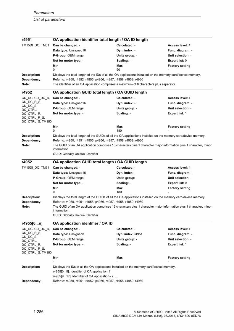
Parameters
List of parameters
1-286 © Siemens AG 2009 - 2013 All Rights ReservedSINAMICS DCM List Manual (LH8), 06/2013, 6RX1800-0ED76
Description: Displays the total length of the IDs of all the OA applications installed on the memory card/device memory.
Dependency: Refer to: r4950, r4952, r4955, p4956, r4957, r4958, r4959, r4960
Note: The identifier of an OA application comprises a maximum of 8 characters plus separator.
Description: Displays the total length of the GUIDs of all the OA applications installed on the memory card/device memory.
Dependency: Refer to: r4950, r4951, r4955, p4956, r4957, r4958, r4959, r4960
Note: The GUID of an OA application comprises 16 characters plus 1 character major information plus 1 character, minor information.
GUID: Globally Unique IDentifier
Description: Displays the IDs of all the OA applications installed on the memory card/device memory.
r4955[0...8]: Identifier of OA application 1
r4955[9...17]: Identifier of OA applications 2, ...
Dependency: Refer to: r4950, r4951, r4952, p4956, r4957, r4958, r4959, r4960
r4951 OA application identifier total length / OA ID lengthTM15DI_DO, TM31 Can be changed: - Calculated: - Access level: 4
Data type: Unsigned16 Dyn. index: - Func. diagram: -
P-Group: OEM range Units group: - Unit selection: -
Not for motor type: - Scaling: - Expert list: 0
Min Max Factory setting 0 90 -
r4952 OA application GUID total length / OA GUID lengthCU_DC, CU_DC_R, CU_DC_R_S, CU_DC_S, DC_CTRL, DC_CTRL_R, DC_CTRL_R_S, DC_CTRL_S, TM150
Can be changed: - Calculated: - Access level: 4
Data type: Unsigned16 Dyn. index: - Func. diagram: -
P-Group: OEM range Units group: - Unit selection: -
Not for motor type: - Scaling: - Expert list: 1
Min Max Factory setting 0 180 -
r4952 OA application GUID total length / OA GUID lengthTM15DI_DO, TM31 Can be changed: - Calculated: - Access level: 4
Data type: Unsigned16 Dyn. index: - Func. diagram: -
P-Group: OEM range Units group: - Unit selection: -
Not for motor type: - Scaling: - Expert list: 0
Min Max Factory setting 0 180 -
r4955[0...n] OA application identifier / OA IDCU_DC, CU_DC_R, CU_DC_R_S, CU_DC_S, DC_CTRL, DC_CTRL_R, DC_CTRL_R_S, DC_CTRL_S, TM150
Can be changed: - Calculated: - Access level: 4
Data type: Unsigned8 Dyn. index: r4951 Func. diagram: -
P-Group: OEM range Units group: - Unit selection: -
Not for motor type: - Scaling: - Expert list: 1
Min Max Factory setting - - -

List of parameters
Parameters
1-287© Siemens AG 2009 - 2013 All Rights ReservedSINAMICS DCM List Manual (LH8), 06/2013, 6RX1800-0ED76
Notice: If there is no OA application, then it is not possible to access an index.
Description: Displays the IDs of all the OA applications installed on the memory card/device memory.
r4955[0...8]: Identifier of OA application 1
r4955[9...17]: Identifier of OA applications 2, ...
Dependency: Refer to: r4950, r4951, r4952, p4956, r4957, r4958, r4959, r4960
Notice: If there is no OA application, then it is not possible to access an index.
Description: Setting to activate the OA applications installed on the memory card/device memory.
r4956[0]: Activates OA application 1
r4956[1]: Activates OA application 2, ...
Value: 0: OA application inactive1: OA application active
Dependency: Refer to: r4950, r4951, r4952, r4955, r4957, r4958, r4959, r4960
Notice: If there is no OA application, then it is not possible to access an index.
r4955[0...n] OA application identifier / OA IDTM15DI_DO, TM31 Can be changed: - Calculated: - Access level: 4
Data type: Unsigned8 Dyn. index: r4951 Func. diagram: -
P-Group: OEM range Units group: - Unit selection: -
Not for motor type: - Scaling: - Expert list: 0
Min Max Factory setting - - -
p4956[0...n] OA application activation / OA actCU_DC, CU_DC_R, CU_DC_R_S, CU_DC_S, DC_CTRL, DC_CTRL_R, DC_CTRL_R_S, DC_CTRL_S, TM150
Can be changed: C1, T Calculated: - Access level: 4
Data type: Integer16 Dyn. index: r4950 Func. diagram: -
P-Group: OEM range Units group: - Unit selection: -
Not for motor type: - Scaling: - Expert list: 1
Min Max Factory setting 0 1 0
p4956[0...n] OA application activation / OA actTM15DI_DO, TM31 Can be changed: C1, T Calculated: - Access level: 4
Data type: Integer16 Dyn. index: r4950 Func. diagram: -
P-Group: OEM range Units group: - Unit selection: -
Not for motor type: - Scaling: - Expert list: 0
Min Max Factory setting 0 1 0

Parameters
List of parameters
1-288 © Siemens AG 2009 - 2013 All Rights ReservedSINAMICS DCM List Manual (LH8), 06/2013, 6RX1800-0ED76
Description: Displays the versions of the OA applications installed on the memory card/device memory.
r4957[0]: Version of OA application 1
r4957[1]: Version of OA application 2, ...
Dependency: Refer to: r4950, r4951, r4952, r4955, p4956, r4958, r4959, r4960
Notice: If there is no OA application, then it is not possible to access an index.
Note: Example:
The value 1010100 should be interpreted as V01.01.01.00.
Description: Displays the interface versions of the OA applications installed on the memory card/device memory.
r4958[0]: Interface version of OA application 1
r4958[1]: Interface version of OA applications 2, ...
Dependency: Refer to: r4950, r4951, r4952, r4955, p4956, r4957, r4959, r4960
Notice: If there is no OA application, then it is not possible to access an index.
Note: Example:
The value 1010100 should be interpreted as V01.01.01.00.
r4957[0...n] OA application version / OA versionCU_DC, CU_DC_R, CU_DC_R_S, CU_DC_S, DC_CTRL, DC_CTRL_R, DC_CTRL_R_S, DC_CTRL_S, TM150
Can be changed: - Calculated: - Access level: 4
Data type: Unsigned32 Dyn. index: r4950 Func. diagram: -
P-Group: OEM range Units group: - Unit selection: -
Not for motor type: - Scaling: - Expert list: 1
Min Max Factory setting 0 4294967295 -
r4957[0...n] OA application version / OA versionTM15DI_DO, TM31 Can be changed: - Calculated: - Access level: 4
Data type: Unsigned32 Dyn. index: r4950 Func. diagram: -
P-Group: OEM range Units group: - Unit selection: -
Not for motor type: - Scaling: - Expert list: 0
Min Max Factory setting 0 4294967295 -
r4958[0...n] OA application interface version / OA int_versionCU_DC, CU_DC_R, CU_DC_R_S, CU_DC_S, DC_CTRL, DC_CTRL_R, DC_CTRL_R_S, DC_CTRL_S, TM150
Can be changed: - Calculated: - Access level: 4
Data type: Unsigned32 Dyn. index: r4950 Func. diagram: -
P-Group: OEM range Units group: - Unit selection: -
Not for motor type: - Scaling: - Expert list: 1
Min Max Factory setting - - -

List of parameters
Parameters
1-289© Siemens AG 2009 - 2013 All Rights ReservedSINAMICS DCM List Manual (LH8), 06/2013, 6RX1800-0ED76
Description: Displays the interface versions of the OA applications installed on the memory card/device memory.
r4958[0]: Interface version of OA application 1
r4958[1]: Interface version of OA applications 2, ...
Dependency: Refer to: r4950, r4951, r4952, r4955, p4956, r4957, r4959, r4960
Notice: If there is no OA application, then it is not possible to access an index.
Note: Example:
The value 1010100 should be interpreted as V01.01.01.00.
Description: Displays the GUIDs of the OA applications installed on the memory card/device memory.
r4959[0...15]: GUID of OA application 1
r4960[16]: Major information of OA application 1
r4960[17]: Minor information of OA application 1
r4959[18...33]: GUID of OA application 2
r4960[34]: Major information of OA application 2
r4960[35]: Minor information of OA application 2, ...
Dependency: Refer to: r4950, r4951, r4952, r4955, p4956, r4957, r4958, r4960
Notice: If there is no OA application, then it is not possible to access an index.
r4958[0...n] OA application interface version / OA int_versionTM15DI_DO, TM31 Can be changed: - Calculated: - Access level: 4
Data type: Unsigned32 Dyn. index: r4950 Func. diagram: -
P-Group: OEM range Units group: - Unit selection: -
Not for motor type: - Scaling: - Expert list: 0
Min Max Factory setting - - -
r4959[0...n] OA application GUID / OA GUIDCU_DC, CU_DC_R, CU_DC_R_S, CU_DC_S, DC_CTRL, DC_CTRL_R, DC_CTRL_R_S, DC_CTRL_S, TM150
Can be changed: - Calculated: - Access level: 4
Data type: Unsigned8 Dyn. index: r4952 Func. diagram: -
P-Group: OEM range Units group: - Unit selection: -
Not for motor type: - Scaling: - Expert list: 1
Min Max Factory setting - - -
r4959[0...n] OA application GUID / OA GUIDTM15DI_DO, TM31 Can be changed: - Calculated: - Access level: 4
Data type: Unsigned8 Dyn. index: r4952 Func. diagram: -
P-Group: OEM range Units group: - Unit selection: -
Not for motor type: - Scaling: - Expert list: 0
Min Max Factory setting - - -

Parameters
List of parameters
1-290 © Siemens AG 2009 - 2013 All Rights ReservedSINAMICS DCM List Manual (LH8), 06/2013, 6RX1800-0ED76
Description: Displays the GUIDs of the drive object of the OA applications installed on the memory card/device memory.
r4960[0...15]: GUID of this drive object of OA application 1
r4960[16]: Major information of this drive object of OA application 1
r4960[17]: Minor information of this drive object of OA application 1
r4960[18...33]: GUID of this drive object of OA application 2
r4960[34]: Major information of this drive object of OA application 2
r4960[35]: Minor information of this drive object of OA application 2, ...
Dependency: Refer to: r4950, r4951, r4952, r4955, p4956, r4957, r4958, r4959
Notice: If there is no OA application, then it is not possible to access an index.
Description: Only for service purposes.
r4960[0...n] OA application GUID drive object / OA GUID DOCU_DC, CU_DC_R, CU_DC_R_S, CU_DC_S, DC_CTRL, DC_CTRL_R, DC_CTRL_R_S, DC_CTRL_S, TM150
Can be changed: - Calculated: - Access level: 4
Data type: Unsigned8 Dyn. index: r4952 Func. diagram: -
P-Group: OEM range Units group: - Unit selection: -
Not for motor type: - Scaling: - Expert list: 1
Min Max Factory setting - - -
r4960[0...n] OA application GUID drive object / OA GUID DOTM15DI_DO, TM31 Can be changed: - Calculated: - Access level: 4
Data type: Unsigned8 Dyn. index: r4952 Func. diagram: -
P-Group: OEM range Units group: - Unit selection: -
Not for motor type: - Scaling: - Expert list: 0
Min Max Factory setting - - -
p4961[0...n] OA application logbook module selection / OA logbook moduleCU_DC, CU_DC_R, CU_DC_R_S, CU_DC_S, DC_CTRL, DC_CTRL_R, DC_CTRL_R_S, DC_CTRL_S, TM150
Can be changed: T Calculated: - Access level: 4
Data type: Unsigned32 Dyn. index: r4950 Func. diagram: -
P-Group: OEM range Units group: - Unit selection: -
Not for motor type: - Scaling: - Expert list: 1
Min Max Factory setting 0000 hex FFFF FFFF hex 0000 hex

List of parameters
Parameters
1-291© Siemens AG 2009 - 2013 All Rights ReservedSINAMICS DCM List Manual (LH8), 06/2013, 6RX1800-0ED76
Description: Only for service purposes.
Description: Displays the number of invalid OA applications installed on the memory card/device memory.
Dependency: Refer to: r4976, r4978, r4979
Note: OA: Open Architecture
Description: Displays the total length of the IDs of all the invalid OA applications installed on the memory card/device memory.
Dependency: Refer to: r4975, r4978, r4979
Note: The identifier of an invalid OA application comprises a maximum of 8 characters plus separator.
Description: Displays the IDs of all the invalid OA applications installed on the memory card/device memory.
r4978[0...8]: Identifier of invalid OA application 1
r4978[9...17]: Identifier of invalid OA application 2, ...
Dependency: Refer to: r4975, r4976, r4979
Notice: If there is no invalid OA application, then it is not possible to access an index.
p4961[0...n] OA application logbook module selection / OA logbook moduleTM15DI_DO, TM31 Can be changed: T Calculated: - Access level: 4
Data type: Unsigned32 Dyn. index: r4950 Func. diagram: -
P-Group: OEM range Units group: - Unit selection: -
Not for motor type: - Scaling: - Expert list: 0
Min Max Factory setting 0000 hex FFFF FFFF hex 0000 hex
r4975 OA application invalid number / OA inv no.CU_DC, CU_DC_R, CU_DC_R_S, CU_DC_S
Can be changed: - Calculated: - Access level: 4
Data type: Unsigned16 Dyn. index: - Func. diagram: -
P-Group: OEM range Units group: - Unit selection: -
Not for motor type: - Scaling: - Expert list: 1
Min Max Factory setting - - -
r4976 OA application invalid identifier total length / OA inv ID lengthCU_DC, CU_DC_R, CU_DC_R_S, CU_DC_S
Can be changed: - Calculated: - Access level: 4
Data type: Unsigned16 Dyn. index: - Func. diagram: -
P-Group: OEM range Units group: - Unit selection: -
Not for motor type: - Scaling: - Expert list: 1
Min Max Factory setting - - -
r4978[0...n] OA application invalid identifier / OA inv IDCU_DC, CU_DC_R, CU_DC_R_S, CU_DC_S
Can be changed: - Calculated: - Access level: 4
Data type: Unsigned8 Dyn. index: r4976 Func. diagram: -
P-Group: OEM range Units group: - Unit selection: -
Not for motor type: - Scaling: - Expert list: 1
Min Max Factory setting - - -

Parameters
List of parameters
1-292 © Siemens AG 2009 - 2013 All Rights ReservedSINAMICS DCM List Manual (LH8), 06/2013, 6RX1800-0ED76
Description: Displays the error code of the invalid OA applications installed on the memory card/device memory.
r4979[0]: Fault value of OA application 1
r4979[1]: Fault value of OA application 2, ...
Dependency: Refer to: r4975, r4976, r4978
Notice: If there is no invalid OA application, then it is not possible to access an index.
Note: The value in the error code must be interpreted in binary form. The bits have the following meaning:
Bit 0: Incompatible OA interface version.
Bit 1: OA application could not be loaded.
Bit 2: Incorrect description files.
Bit 3: OA application does not define a CPU type.
Bit 4: OA application for this device not supported (incorrect CPU type).
Bit 5: OA application for this device not supported (incorrect type ID).
Bit 6: Incorrect description files (Const/Startup incompatible).
Description: Displays the actual serial number of the Control Unit.
The individual characters of the serial number are displayed in the ASCII code in the indices.
For the commissioning software, the ASCII characters are displayed uncoded.
Dependency: Refer to: p7765, p7766, p7767, p7768
Notice: An ASCII table (excerpt) can be found, for example, in the appendix to the List Manual.
Note: KHP: Know-How Protection
Description: Sets the reference serial number for the Control Unit.
Using this parameter, if a Control Unit and/or a memory card is replaced at the end customer, the OEM can again adapt the project to the modified hardware.
Dependency: Refer to: p7765, p7766, p7767, p7768
Note: KHP: Know-How Protection
- The OEM may only change this parameter for the use case "Sending encrypted SINAMICS data".
- SINAMICS only evaluates this parameter when powering up from the encrypted "Load into file system..." output or when powering up from the encrypted PS files. The evaluation is only made when know-how protection and mem-ory card copy protection have been activated.
r4979[0...n] OA application invalid error code / OA inv error codeCU_DC, CU_DC_R, CU_DC_R_S, CU_DC_S
Can be changed: - Calculated: - Access level: 4
Data type: Unsigned32 Dyn. index: r4975 Func. diagram: -
P-Group: OEM range Units group: - Unit selection: -
Not for motor type: - Scaling: - Expert list: 1
Min Max Factory setting - - -
r7758[0...19] KHP Control Unit serial number / KHP CU ser_noCU_DC, CU_DC_R, CU_DC_R_S, CU_DC_S
Can be changed: - Calculated: - Access level: 3
Data type: Unsigned8 Dyn. index: - Func. diagram: -
P-Group: - Units group: - Unit selection: -
Not for motor type: - Scaling: - Expert list: 1
Min Max Factory setting - - -
p7759[0...19] KHP Control Unit reference serial number / KHP CU ref ser_noCU_DC, CU_DC_R, CU_DC_R_S, CU_DC_S
Can be changed: T Calculated: - Access level: 3
Data type: Unsigned8 Dyn. index: - Func. diagram: -
P-Group: - Units group: - Unit selection: -
Not for motor type: - Scaling: - Expert list: 1
Min Max Factory setting - - -

List of parameters
Parameters
1-293© Siemens AG 2009 - 2013 All Rights ReservedSINAMICS DCM List Manual (LH8), 06/2013, 6RX1800-0ED76
Description: Displays the status for the write protection and know-how protection.
Dependency: Refer to: p7761, p7765, p7766, p7767, p7768
Note: KHP: Know-How Protection
Re bit 00:
Write protection can be activated/deactivated via p7761 on the Control Unit.
Re bit 01:
The know-how protection can be activated by entering a password (p7766 ... p7768).
Re bit 02:
If it has already been activated, know-how protection can be temporarily deactivated by entering the valid password in p7766. In this case, bit 1 = 0 and bit 2 = 1 offset.
Re bit 03:
Know-how protection cannot be deactivated, as p7766 is not entered in the OEM exception list (only the factory set-ting is possible). This bit is only set if know-how protection is active (bit 1 = 1) and p7766 has not been entered in the OEM exception list.
Re bit 04:
When know-how protection has been activated, the contents of the memory card (parameter and DCC data) can be additionally protected against being used with other memory cards. This bit is only set if know-how protection is active and p7765 = 1.
Description: Setting for activating/de-activating the write protection for adjustable parameters.
Value: 0: Deactivate write protection1: Activate write protection
Dependency: Refer to: r7760
Notice: While write protection is active, a download is prevented; however, it is still possible to restore the factory settings.
Note: Parameters with the "WRITE_NO_LOCK" attributes are excluded from the write protection.
A product-specific list of these parameters is also available in the corresponding List Manual.
r7760 Write protection/know-how protection status / Wr_prot/KHP statAll objects Can be changed: - Calculated: - Access level: 3
Data type: Unsigned16 Dyn. index: - Func. diagram: -
P-Group: - Units group: - Unit selection: -
Not for motor type: - Scaling: - Expert list: 1
Min Max Factory setting - - -
Bit field: Bit Signal name 1 signal 0 signal FP00 Write protection active Yes No -01 Know-how protection active Yes No -02 Know-how protection temporarily withdrawn Yes No -03 Know-how protection cannot be deactivated Yes No -04 Memory card copy protection active Yes No -
p7761 Write protection / Write protectionCU_DC, CU_DC_R, CU_DC_R_S, CU_DC_S
Can be changed: U, T Calculated: - Access level: 3
Data type: Integer16 Dyn. index: - Func. diagram: -
P-Group: - Units group: - Unit selection: -
Not for motor type: - Scaling: - Expert list: 1
Min Max Factory setting 0 1 0

Parameters
List of parameters
1-294 © Siemens AG 2009 - 2013 All Rights ReservedSINAMICS DCM List Manual (LH8), 06/2013, 6RX1800-0ED76
Description: Sets the behavior for write protection when accessing via multi-master fieldbus systems (e.g. CAN, BACnet).
Value: 0: Write access independent of p77611: Write access dependent on p7761
Dependency: Refer to: r7760, p7761
Description: Sets the number of parameters for the OEM exception list (p7764[0...n]).
p7764[0...n], with n = p7763 - 1
Dependency: Refer to: p7764
Note: KHP: Know-How Protection
Even if know-how protection is set, parameters in this list can be read and written to.
Description: OEM exception list (p7764[0...n] for setting parameters that should be excluded from know-how protection.
p7764[0...n], with n = p7763 - 1
Dependency: The number of indices depends on p7763.
Refer to: p7763
p7762 Write protection multi-master fieldbus system access behavior / Fieldbus acc_behavCU_DC, CU_DC_R, CU_DC_R_S, CU_DC_S
Can be changed: U, T Calculated: - Access level: 3
Data type: Integer16 Dyn. index: - Func. diagram: -
P-Group: - Units group: - Unit selection: -
Not for motor type: - Scaling: - Expert list: 1
Min Max Factory setting 0 1 0
p7763 KHP OEM exception list number of indices for p7764 / KHP OEM qty p7764All objects Can be changed: U, T Calculated: - Access level: 3
Data type: Unsigned16 Dyn. index: - Func. diagram: -
P-Group: - Units group: - Unit selection: -
Not for motor type: - Scaling: - Expert list: 1
Min Max Factory setting 1 500 1
p7764[0...n] KHP OEM exception list / KHP OEM excep listCU_DC, CU_DC_R, CU_DC_R_S, CU_DC_S
Can be changed: U, T Calculated: - Access level: 3
Data type: Unsigned16 Dyn. index: p7763 Func. diagram: -
P-Group: - Units group: - Unit selection: -
Not for motor type: - Scaling: - Expert list: 1
Min Max Factory setting 0 65535 [0] 7766
[1...499] 0
p7764[0...n] KHP OEM exception list / KHP OEM excep listDC_CTRL, DC_CTRL_R, DC_CTRL_R_S, DC_CTRL_S, TM150, TM15DI_DO, TM31
Can be changed: U, T Calculated: - Access level: 3
Data type: Unsigned16 Dyn. index: p7763 Func. diagram: -
P-Group: - Units group: - Unit selection: -
Not for motor type: - Scaling: - Expert list: 1
Min Max Factory setting 0 65535 0

List of parameters
Parameters
1-295© Siemens AG 2009 - 2013 All Rights ReservedSINAMICS DCM List Manual (LH8), 06/2013, 6RX1800-0ED76
Note: KHP: Know-How Protection
Even if know-how protection is set, parameters in this list can be read and written to.
Description: Setting for activating/de-activating copy protection for the memory card.
This means that the OEM can define whether the parameters and DCC data encrypted on the memory card should be protected before using on other memory cards.
Value: 0: Deactivating protection1: Activating protection
Dependency: Refer to: p7766, p7767, p7768
Note: KHP: Know-How Protection
The memory card copy protection is only effective when the know-how protection has been activated.
Description: Sets the password for know-how protection.
Example of a password:
123aBc = 49 50 51 97 66 99 dec (ASCII characters)
[0] = character 1 (e.g. 49 dec)
[1] = character 2 (e.g. 50 dec)
...
[5] = character 6 (e.g. 99 dec)
[29] = 0 dec (completes the entry)
Dependency: Refer to: p7767, p7768
Notice: An ASCII table (excerpt) can be found, for example, in the appendix to the List Manual.
When using the STARTER commissioning software, the password should be entered using the associated dialogs.
The following rules apply when entering the password:
- Password entry must start with p7766[0].
- No gaps are permissible in the password.
- Entering a password is completed when writing to p7766[29] (p7766[29] = 0 for passwords less than 30 charac-ters).
Note: KHP: Know-How Protection
When reading, p7766[0...29] = 42 dec (ASCII character = "*") is displayed.
Parameters with the "KHP_WRITE_NO_LOCK" attribute are not involved in the know-how protection.
Parameters with the "KHP_ACTIVE_READ" attribute can be read even when know-how protection is activated.
A product-specific list of these parameters is also available in the corresponding List Manual.
p7765 KHP memory card copy protection / KHP copy protectCU_DC, CU_DC_R, CU_DC_R_S, CU_DC_S
Can be changed: U, T Calculated: - Access level: 3
Data type: Integer16 Dyn. index: - Func. diagram: -
P-Group: - Units group: - Unit selection: -
Not for motor type: - Scaling: - Expert list: 1
Min Max Factory setting 0 1 0
p7766[0...29] KHP password input / KHP passw inputCU_DC, CU_DC_R, CU_DC_R_S, CU_DC_S
Can be changed: U, T Calculated: - Access level: 3
Data type: Unsigned16 Dyn. index: - Func. diagram: -
P-Group: - Units group: - Unit selection: -
Not for motor type: - Scaling: - Expert list: 0
Min Max Factory setting - - -

Parameters
List of parameters
1-296 © Siemens AG 2009 - 2013 All Rights ReservedSINAMICS DCM List Manual (LH8), 06/2013, 6RX1800-0ED76
Description: Sets the new password for know-how protection.
Dependency: Refer to: p7766, p7768
Note: KHP: Know-How Protection
When reading, p7767[0...29] = 42 dec (ASCII character = "*") is displayed.
Description: Confirms the new password for know-how protection.
Dependency: Refer to: p7766, p7767
Note: KHP: Know-How Protection
When reading, p7768[0...29] = 42 dec (ASCII character = "*") is displayed.
Description: Sets the reference serial number for the memory card.
Using this parameter, if a Control Unit and/or a memory card is replaced at the end customer, the OEM can again adapt the project to the modified hardware.
Dependency: Refer to: p7765, p7766, p7767, p7768
Note: KHP: Know-How Protection
- The OEM may only change this parameter for the use case "Sending encrypted SINAMICS data".
- SINAMICS only evaluates this parameter when powering up from the encrypted "Load into file system..." output or when powering up from the encrypted PS files. The evaluation is only made when know-how protection and mem-ory card copy protection have been activated.
Description: Sets the action to be executed for NVRAM data.
At the end of the action the value is automatically set to 0.
p7767[0...29] KHP password new / KHP passw newCU_DC, CU_DC_R, CU_DC_R_S, CU_DC_S
Can be changed: U, T Calculated: - Access level: 3
Data type: Unsigned16 Dyn. index: - Func. diagram: -
P-Group: - Units group: - Unit selection: -
Not for motor type: - Scaling: - Expert list: 0
Min Max Factory setting - - -
p7768[0...29] KHP password confirmation / KHP passw confirmCU_DC, CU_DC_R, CU_DC_R_S, CU_DC_S
Can be changed: U, T Calculated: - Access level: 3
Data type: Unsigned16 Dyn. index: - Func. diagram: -
P-Group: - Units group: - Unit selection: -
Not for motor type: - Scaling: - Expert list: 0
Min Max Factory setting - - -
p7769[0...20] KHP memory card reference serial number / KHP mem ref ser_noCU_DC, CU_DC_R, CU_DC_R_S, CU_DC_S
Can be changed: T Calculated: - Access level: 3
Data type: Unsigned8 Dyn. index: - Func. diagram: -
P-Group: - Units group: - Unit selection: -
Not for motor type: - Scaling: - Expert list: 1
Min Max Factory setting - - -
p7770 NVRAM action / NVRAM actionTM150, TM15DI_DO, TM31
Can be changed: T Calculated: - Access level: 3
Data type: Integer16 Dyn. index: - Func. diagram: -
P-Group: - Units group: - Unit selection: -
Not for motor type: - Scaling: - Expert list: 1
Min Max Factory setting 0 3 0

List of parameters
Parameters
1-297© Siemens AG 2009 - 2013 All Rights ReservedSINAMICS DCM List Manual (LH8), 06/2013, 6RX1800-0ED76
Value: 0: Inactive1: Load NVRAM data to parameters2: Load parameters to NVRAM3: Reset
Notice: After action p7770 = 1 no more pulses may be enabled.
After action p7770 = 2, it is essential that parameters are backed up (p0977 = 1) and that a warm restart is then per-formed (p0009 = 30, p0976 = 2, 3). This will apply the values written.
Note: If value = 1:
This action loads the NVRAM data to the parameters.
If value = 2:
This action loads the parameters to the NVRAM.
If value = 3:
This action sets parameters p7771 ... p7774 to the factory setting.
It is recommended to avoid placing unnecessary load on the subsequent upload/download operation.
Description: Setting to backup/import/delete NVRAM data.
NVRAM data are non-volatile data in the device (e.g. fault buffer).
For NVRAM data actions, the following data are excluded:
- Crash diagnostics
- CU operating hours counter
- CU temperature
- Safety logbook
Value: 0: Inactive1: NVRAM data backup to memory card2: Import NVRAM data from the memory card3: Delete NVRAM data in the device10: Error when clearing11: Error when backing up, memory card not available12: Error when backing up, insufficient memory space13: Error when backing up14: Error when importing, memory card not available15: Error when importing, checksum error16: Error when importing, no NVRAM data available17: Error when importing
Notice: Re value = 2, 3:
These actions are only possible when pulses are inhibited.
Note: After the action has been successfully completed, the parameter is automatically set to zero.
The actions importing and deleting NVRAM data immediately initiate a warm restart.
If the procedure was not successfully completed, then an appropriate fault value is displayed (p7775 >= 10).
Description: Sets the component number of the DRIVE-CLiQ component whose parameters are to be accessed.
p7775 NVRAM data backup/import/delete / NVRAM backupCU_DC, CU_DC_R, CU_DC_R_S, CU_DC_S
Can be changed: C1, U, T Calculated: - Access level: 3
Data type: Integer16 Dyn. index: - Func. diagram: -
P-Group: - Units group: - Unit selection: -
Not for motor type: - Scaling: - Expert list: 1
Min Max Factory setting 0 17 0
p7820 DRIVE-CLiQ component component number / DQ compo_noCU_DC, CU_DC_R, CU_DC_R_S, CU_DC_S
Can be changed: U, T Calculated: - Access level: 4
Data type: Unsigned16 Dyn. index: - Func. diagram: -
P-Group: - Units group: - Unit selection: -
Not for motor type: - Scaling: - Expert list: 1
Min Max Factory setting 0 65535 0

Parameters
List of parameters
1-298 © Siemens AG 2009 - 2013 All Rights ReservedSINAMICS DCM List Manual (LH8), 06/2013, 6RX1800-0ED76
Dependency: Refer to: p7821, p7822, r7823
Description: Sets the parameter number to access a parameter of a DRIVE-CLiQ component.
Dependency: Refer to: p7820, p7822, r7823
Description: Sets the parameter index to access a parameter of a DRIVE-CLiQ component.
Dependency: Refer to: p7820, p7821, r7823
Description: Displays the parameter value read from the DRIVE-CLiQ component.
Dependency: Refer to: p7820, p7821, p7822
Description: Displays the firmware and EPROM versions of the DRIVE-CLiQ component selected using p7828[1].
Index: [0] = Reference firmware version[1] = Actual firmware version[2] = EPROM0 version[3] = EPROM1 version[4] = EPROM2 version[5] = EPROM3 version[6] = EPROM4 version
Dependency: Refer to: p7828
Note: Reference firmware version: Version on the memory card/device memory.
Current firmware version: Actual version of the DRIVE-CLiQ component.
EPROM version: Current EPROM version of the DRIVE-CLiQ component.
p7821 DRIVE-CLiQ component parameter number / DQ para_noCU_DC, CU_DC_R, CU_DC_R_S, CU_DC_S
Can be changed: U, T Calculated: - Access level: 4
Data type: Unsigned16 Dyn. index: - Func. diagram: -
P-Group: - Units group: - Unit selection: -
Not for motor type: - Scaling: - Expert list: 1
Min Max Factory setting 0 65535 0
p7822 DRIVE-CLiQ component parameter index / DQ para_indexCU_DC, CU_DC_R, CU_DC_R_S, CU_DC_S
Can be changed: U, T Calculated: - Access level: 4
Data type: Unsigned16 Dyn. index: - Func. diagram: -
P-Group: - Units group: - Unit selection: -
Not for motor type: - Scaling: - Expert list: 1
Min Max Factory setting 0 65535 0
r7823 DRIVE-CLiQ component read parameter value / Read DQ valueCU_DC, CU_DC_R, CU_DC_R_S, CU_DC_S
Can be changed: - Calculated: - Access level: 4
Data type: Unsigned32 Dyn. index: - Func. diagram: -
P-Group: - Units group: - Unit selection: -
Not for motor type: - Scaling: - Expert list: 1
Min Max Factory setting - - -
r7825[0...6] DRIVE-CLiQ component versions / DQ versionCU_DC, CU_DC_R, CU_DC_R_S, CU_DC_S
Can be changed: - Calculated: - Access level: 3
Data type: Unsigned32 Dyn. index: - Func. diagram: -
P-Group: - Units group: - Unit selection: -
Not for motor type: - Scaling: - Expert list: 1
Min Max Factory setting - - -

List of parameters
Parameters
1-299© Siemens AG 2009 - 2013 All Rights ReservedSINAMICS DCM List Manual (LH8), 06/2013, 6RX1800-0ED76
Description: Sets the behavior for the automatic firmware update of the DRIVE-CLiQ components.
Value: 0: De-activated1: Upgrade and downgrade2: Upgrade
Notice: If this parameter is changed, it only becomes effective the next time that the drive system boots.
Note: The firmware is automatically updated when the system boots. The boot can take several minutes.
After the update has been completed, it is necessary to carry out a new POWER ON (power-down/power-up) for the components involved.
The firmware update procedure is displayed as follows:
Control Unit (LED RDY):
Flashes yellow with 0.5 Hz --> firmware is being updated.
Flashing yellow with 2 Hz --> POWER ON is required for the components involved.
Components involved:
Flashing red/green with 0.5 Hz --> firmware is being updated.
Flashing red/green with 2 Hz --> POWER ON of the components is required.
Only components from firmware version 2.5 support the red/green flashing at 2 Hz.
Description: Displays the progress when updating the firmware of the DRIVE-CLiQ components.
Description: Sets the component number for the required DRIVE-CLiQ component.
Index 0:
Component number of the DRIVE-CLiQ component for which a firmware download is to be made.
Index 1:
Component number of the DRIVE-CLiQ component for which the reference firmware version, saved in r7825 on the memory card/device memory, is to be displayed.
Index: [0] = Firmware download[1] = Reference firmware version
Dependency: Refer to: p0121, p0141, p0151, p7829
Note: For p7828[0] = 399, the firmware for all of the existing components is downloaded.
The firmware download is started with p7829 = 1.
p7826 Firmware update automatic / FW update autoCU_DC, CU_DC_R, CU_DC_R_S, CU_DC_S
Can be changed: U, T Calculated: - Access level: 3
Data type: Integer16 Dyn. index: - Func. diagram: -
P-Group: - Units group: - Unit selection: -
Not for motor type: - Scaling: - Expert list: 1
Min Max Factory setting 0 2 1
r7827 Firmware update progress display / FW update progressCU_DC, CU_DC_R, CU_DC_R_S, CU_DC_S
Can be changed: - Calculated: - Access level: 3
Data type: FloatingPoint32 Dyn. index: - Func. diagram: -
P-Group: - Units group: - Unit selection: -
Not for motor type: - Scaling: - Expert list: 1
Min Max Factory setting - [%] - [%] - [%]
p7828[0...1] Firmware download component number / FW downl comp_noCU_DC, CU_DC_R, CU_DC_R_S, CU_DC_S
Can be changed: U, T Calculated: - Access level: 3
Data type: Unsigned16 Dyn. index: - Func. diagram: -
P-Group: - Units group: - Unit selection: -
Not for motor type: - Scaling: - Expert list: 1
Min Max Factory setting 0 399 0

Parameters
List of parameters
1-300 © Siemens AG 2009 - 2013 All Rights ReservedSINAMICS DCM List Manual (LH8), 06/2013, 6RX1800-0ED76
Description: Activating the firmware download for the DRIVE-CLiQ components specified in p7828.
1: Activate download.
-1: activate the download and carry out a reset.
0: Download successfully completed.
> 1: Fault code
011: DRIVE-CLiQ component has detected a checksum error.
015: The selected DRIVE-CLiQ components did not accept the contents of the firmware file.
018: Firmware version is too old and is not accepted by the component.
019: Firmware version is not suitable for the hardware release of the component.
101: After several communication attempts, no response from the DRIVE-CLiQ component.
140: Firmware file for the DRIVE-CLiQ component not available on the memory card/device memory.
143: Component has not changed to the mode for firmware download. It was not possible to delete the existing firmware.
144: When checking the firmware that was downloaded (checksum), the component detected a fault. It is possible that the file on the memory card/device memory is defective.
145: Checking the loaded firmware (checksum) was not completed by the component in the appropriate time.
156: Component with the specified component number is not available.
Additional values:
Only for internal Siemens troubleshooting.
Dependency: Refer to: p7828
Note: p7829 is automatically set to 0 after the firmware has been successfully downloaded.
The new firmware only becomes active at the next system run-up.
Description: Selects a telegram whose contents should be shown in r7831 ... r7836.
Value: 0: Reserved1: First cyclic receive telegram sensor 12: First cyclic receive telegram sensor 23: First cyclic receive telegram sensor 3
Dependency: Refer to: r7831, r7832, r7833, r7834, r7835, r7836
Description: Displays the signals contained in the selected telegram (p7830).
p7829 Activate firmware download / FW download actCU_DC, CU_DC_R, CU_DC_R_S, CU_DC_S
Can be changed: U, T Calculated: - Access level: 3
Data type: Integer16 Dyn. index: - Func. diagram: -
P-Group: - Units group: - Unit selection: -
Not for motor type: - Scaling: - Expert list: 1
Min Max Factory setting -1 999 0
p7830 Telegram diagnostics selection / Telegr diag selDC_CTRL, DC_CTRL_R, DC_CTRL_R_S, DC_CTRL_S
Can be changed: T Calculated: - Access level: 4
Data type: Integer16 Dyn. index: - Func. diagram: -
P-Group: - Units group: - Unit selection: -
Not for motor type: - Scaling: - Expert list: 1
Min Max Factory setting 0 3 0
r7831[0...15] Telegram diagnostics signals / Telegr diag sigDC_CTRL, DC_CTRL_R, DC_CTRL_R_S, DC_CTRL_S
Can be changed: - Calculated: - Access level: 4
Data type: Integer16 Dyn. index: - Func. diagram: -
P-Group: - Units group: - Unit selection: -
Not for motor type: - Scaling: - Expert list: 1
Min Max Factory setting 0 15157 -

List of parameters
Parameters
1-301© Siemens AG 2009 - 2013 All Rights ReservedSINAMICS DCM List Manual (LH8), 06/2013, 6RX1800-0ED76
Value: 0: UNUSED1: UNKNOWN102: SAPAR_ID_DSA_ALARM110: SAPAR_ALARMBITS_FLOAT_0111: SAPAR_ALARMBITS_FLOAT_1112: SAPAR_ALARMBITS_FLOAT_2113: SAPAR_ALARMBITS_FLOAT_3114: SAPAR_ALARMBITS_FLOAT_4115: SAPAR_ALARMBITS_FLOAT_510500: ENC_ID_TIME_PRETRIGGER10501: ENC_ID_TIME_SEND_TELEG_110502: ENC_ID_TIME_CYCLE_FINISHED10503: ENC_ID_TIME_DELTA_FUNMAN10504: ENC_ID_SUBTRACE_CALCTIMES10505: ENC_ID_SYNO_PERIOD10516: ENC_ID_ADC_TRACK_A10517: ENC_ID_ADC_TRACK_B10518: ENC_ID_ADC_TRACK_C10519: ENC_ID_ADC_TRACK_D10520: ENC_ID_ADC_TRACK_A_SAFETY10521: ENC_ID_ADC_TRACK_B_SAFETY10523: ENC_ID_ADC_TEMP_110524: ENC_ID_SUBTRACE_TRACK_A10525: ENC_ID_SUBTRACE_TRACK_B10526: ENC_ID_ADC_TRACK_R10532: ENC_ID_TRACK_AB_X10533: ENC_ID_TRACK_AB_Y10534: ENC_ID_OFFSET_CORR_AB_X10535: ENC_ID_OFFSET_CORR_AB_Y10536: ENC_ID_AB_ABS_VALUE10537: ENC_ID_TRACK_CD_X10538: ENC_ID_TRACK_CD_Y10539: ENC_ID_TRACK_CD_ABS10542: ENC_ID_AB_RAND_X10543: ENC_ID_AB_RAND_Y10544: ENC_ID_AB_RAND_ABS_VALUE10545: ENC_ID_SUBTRACE_ABS_ARRAY10546: ENC_ID_PROC_OFFSET_010547: ENC_ID_PROC_OFFSET_410550: ENC_ID_SUBTRACE_AMPL10564: ENC_SELFTEMP_ACT10565: ENC_ID_MOTOR_TEMP_TOP10566: ENC_ID_MOTOR_TEMP_110580: ENC_ID_RESISTANCE_110590: ENC_ID_ANA_CHAN_A10591: ENC_ID_ANA_CHAN_B10592: ENC_ID_ANA_CHAN_X10593: ENC_ID_ANA_CHAN_Y10596: ENC_ID_AB_ANGLE10597: ENC_ID_CD_ANGLE10598: ENC_ID_MECH_ANGLE_HI10599: ENC_ID_RM_POS_PHI_COMMU10600: ENC_ID_PHI_COMMU10601: ENC_ID_SUBTRACE_ANGLE10612: ENC_ID_DIFF_CD_INC10613: ENC_ID_RM_POS_PHI_COMMU_RFG10628: ENC_ID_MECH_ANGLE10629: ENC_ID_MECH_RM_POS10644: ENC_ID_INIT_VECTOR10645: FEAT_INIT_VECTOR10660: ENC_ID_SENSOR_STATE10661: ENC_ID_BASIC_SYSTEM10662: ENC_ID_REFMARK_STATUS10663: ENC_ID_DSA_STATUS1_SENSOR

Parameters
List of parameters
1-302 © Siemens AG 2009 - 2013 All Rights ReservedSINAMICS DCM List Manual (LH8), 06/2013, 6RX1800-0ED76
10664: ENC_ID_DSA_RMSTAT_HANDSHAKE10665: ENC_ID_DSA_CONTROL1_SENSOR10667: ENC_ID_SAFETY10669: ENC_ID_SUB_STATE10676: ENC_ID_COUNTCORR_SAW_VALUE10677: ENC_ID_COUNTCORR_ABS_VALUE10678: ENC_ID_SAWTOOTH_CORR10680: ENC_ID_SM_XIST1_CORRECTED_QUADRANTS10692: ENC_ID_RESISTANCE_CALIB_INSTANT10693: ENC_ID_SERPROT_POS10723: ENC_ID_ACT_STATEMACHINE_FUNCTION10724: ENC_ID_ACT_FUNMAN_FUNCTION10725: ENC_ID_SAFETY_COUNTER_CRC10728: ENC_ID_SUBTRACE_AREA10740: ENC_ID_POS_ABSOLUTE10741: ENC_ID_POS_REFMARK10742: ENC_ID_SAWTOOTH10743: ENC_ID_SAFETY_PULSE_COUNTER10745: ENC_ID_EIU_ZEROCTRL10756: ENC_ID_DSA_ACTUAL_SPEED10757: ENC_ID_SPEED_DEV_ABS10772: ENC_ID_DSA_POS_XIST110788: ENC_ID_AB_CROSS_CORR10789: ENC_ID_AB_GAIN_Y_CORR10790: ENC_ID_AB_PEAK_CORR11825: ENC_ID_RES_TRANSITION_RATIO11826: ENC_ID_RES_PHASE_SHIFT15150: ENC_ID_SPINDLE_S1_RAW15151: ENC_ID_SPINDLE_S4_RAW15152: ENC_ID_SPINDLE_S5_RAW15155: ENC_ID_SPINDLE_S1_CAL15156: ENC_ID_SPINDLE_S4_CAL15157: ENC_ID_SPINDLE_S5_CAL
Description: Displays the original numerical format of the signals contained in the telegram.
The associated signal number is represented in the appropriate index of r7831.
Value: -1: Unknown0: Boolean1: Signed 1 byte2: Signed 2 byte3: Signed 4 byte4: Signed 8 byte5: Unsigned 1 byte6: Unsigned 2 byte7: Unsigned 4 byte8: Unsigned 8 byte9: Float 4 byte10: Double 8 byte11: mm dd yy HH MM SS MS DOW12: ASCII string13: SINUMERIK frame type14: SINUMERIK axis type
Dependency: Refer to: r7831
r7832[0...15] Telegram diagnostics numerical format / Telegr diag formatDC_CTRL, DC_CTRL_R, DC_CTRL_R_S, DC_CTRL_S
Can be changed: - Calculated: - Access level: 4
Data type: Integer16 Dyn. index: - Func. diagram: -
P-Group: - Units group: - Unit selection: -
Not for motor type: - Scaling: - Expert list: 1
Min Max Factory setting -1 14 -

List of parameters
Parameters
1-303© Siemens AG 2009 - 2013 All Rights ReservedSINAMICS DCM List Manual (LH8), 06/2013, 6RX1800-0ED76
Description: Parameter to display a DSA signal in the unsigned-integer format.
The associated signal number is represented at the appropriate index in r7831.
Description: Parameter to display a DSA signal in the signed-integer format.
The associated signal number is represented at the appropriate index in r7831.
Description: Parameter to display a DSA signal in the float format.
The associated signal number is represented at the appropriate index in r7831.
Description: Displays the units of a DSA signal.
The associated signal number is represented at the appropriate index in r7831.
Value: -1: Unknown0: None1: Millimeter or degrees2: Millimeter3: Degrees4: mm/min or RPM5: Millimeter / min6: Revolutions / min7: m/sec^2 or U/sec^28: m/sec^29: U/sec^210: m/sec^3 or U/sec^311: m/sec^312: U/sec^313: sec
r7833[0...15] Telegram diagnostics unsigned / Telegr diag unsignDC_CTRL, DC_CTRL_R, DC_CTRL_R_S, DC_CTRL_S
Can be changed: - Calculated: - Access level: 4
Data type: Unsigned32 Dyn. index: - Func. diagram: -
P-Group: - Units group: - Unit selection: -
Not for motor type: - Scaling: - Expert list: 1
Min Max Factory setting - - -
r7834[0...15] Telegram diagnostics signed / Telegr diag signDC_CTRL, DC_CTRL_R, DC_CTRL_R_S, DC_CTRL_S
Can be changed: - Calculated: - Access level: 4
Data type: Integer32 Dyn. index: - Func. diagram: -
P-Group: - Units group: - Unit selection: -
Not for motor type: - Scaling: - Expert list: 1
Min Max Factory setting - - -
r7835[0...15] Telegram diagnostics real / Telegr diag realDC_CTRL, DC_CTRL_R, DC_CTRL_R_S, DC_CTRL_S
Can be changed: - Calculated: - Access level: 4
Data type: FloatingPoint32 Dyn. index: - Func. diagram: -
P-Group: - Units group: - Unit selection: -
Not for motor type: - Scaling: - Expert list: 1
Min Max Factory setting - - -
r7836[0...15] Telegram diagnostics unit / Telegr diag unitDC_CTRL, DC_CTRL_R, DC_CTRL_R_S, DC_CTRL_S
Can be changed: - Calculated: - Access level: 4
Data type: Integer16 Dyn. index: - Func. diagram: -
P-Group: - Units group: - Unit selection: -
Not for motor type: - Scaling: - Expert list: 1
Min Max Factory setting -1 147 -

Parameters
List of parameters
1-304 © Siemens AG 2009 - 2013 All Rights ReservedSINAMICS DCM List Manual (LH8), 06/2013, 6RX1800-0ED76
14: 16.667 / sec15: mm/revolution16: ACX_UNIT_COMPENSATION_CORR18: Newton19: Kilogram20: Kilogram meter^221: Percent22: Hertz23: Volt peak-to-peak24: Amps peak-to-peak25: Degrees Celsius26: Degrees28: Millimeter or degrees29: Meters / minute30: Meters / second31: ohm32: Millihenry33: Newton meter34: Newton meter/Ampere35: Volt/Ampere36: Newton meter second / rad38: 31.25 microseconds39: Microseconds40: Milliseconds42: Kilowatt43: Micro amps peak-to-peak44: Volt seconds45: Microvolt seconds46: Micro newton meters47: Amps / volt seconds48: Per mille49: Hertz / second53: Micrometer or millidegrees54: Micrometer55: Millidegrees59: Nanometer61: Newton/Amps62: Volt seconds/meter63: Newton seconds/meter64: Micronewton65: Liters / minute66: Bar67: Cubic centimeters68: Millimeter / volt minute69: Newton/Volt80: Millivolts peak-to-peak81: Volt rms82: Millivolts rms83: Amps rms84: Micro amps rms85: Micrometers / revolution90: Tenths of a second91: Hundredths of a second92: 10 microseconds93: Pulses94: 256 pulses95: Tenths of a pulse96: Revolutions97: 100 revolutions / minute98: 10 revolutions / minute99: 0.1 revolutions / minute100: Thousandth revolution / minute101: Pulses / second102: 100 pulses / second

List of parameters
Parameters
1-305© Siemens AG 2009 - 2013 All Rights ReservedSINAMICS DCM List Manual (LH8), 06/2013, 6RX1800-0ED76
103: 10 revolutions / (minute x seconds)104: 10000 pulses/second^2105: 0.1 Hertz106: 0.01 Hertz107: 0.1 / seconds108: Factor 0.1109: Factor 0.01110: Factor 0.001111: Factor 0.0001112: 0.1 Volt peak-to-peak113: 0.1 Volt peak-to-peak114: 0.1 amps peak-to-peak115: Watt116: 100 Watt117: 10 Watt118: 0.01 percent119: 1/second^3120: 0.01 percent/millisecond121: Pulses / revolution122: Microfarads123: Milliohm124: 0.01 Newton meter125: Kilogram millimeter^2126: Rad / (seconds newton meter)127: Henry128: Kelvin129: Hours130: Kilohertz131: Milliamperes peak-to-peak132: Millifarads133: Meter135: Kilowatt hours136: Percent137: Amps / Volt138: Volt139: Millivolts140: Microvolts141: Amps142: Milliamperes143: Micro amps144: Milliamperes rms145: Millimeter146: Nanometer147: Joules
Description: Displays the actual serial number of the memory card.
The individual characters of the serial number are displayed in the ASCII code in the indices.
Dependency: Refer to: p9920, p9921
Notice: An ASCII table (excerpt) can be found, for example, in the appendix to the List Manual.
Note: Example: displaying the serial number for a memory card:
r7843[0] = 49 dec --> ASCII characters = "1" --> serial number, character 1
r7843[1] = 49 dec --> ASCII characters = "1" --> serial number, character 2
r7843[2] = 49 dec --> ASCII characters = "1" --> serial number, character 3
r7843[0...20] Memory card serial number / Mem_card ser.noCU_DC, CU_DC_R, CU_DC_R_S, CU_DC_S
Can be changed: - Calculated: - Access level: 1
Data type: Unsigned8 Dyn. index: - Func. diagram: -
P-Group: - Units group: - Unit selection: -
Not for motor type: - Scaling: - Expert list: 1
Min Max Factory setting - - -

Parameters
List of parameters
1-306 © Siemens AG 2009 - 2013 All Rights ReservedSINAMICS DCM List Manual (LH8), 06/2013, 6RX1800-0ED76
r7843[3] = 57 dec --> ASCII characters = "9" --> serial number, character 4
r7843[4] = 50 dec --> ASCII characters = "2" --> serial number, character 5
r7843[5] = 51 dec --> ASCII characters = "3" --> serial number, character 6
r7843[6] = 69 dec --> ASCII characters = "E" --> serial number, character 7
r7843[7] = 0 dec --> ASCII characters = " " --> serial number, character 8
...
r7843[19] = 0 dec --> ASCII characters = " " --> serial number, character 20
r7843[20] = 0 dec
Serial number = 111923E
Description: Displays the version of the firmware stored on the device memory.
Index: [0] = Internal[1] = External[2] = Parameter backup
Note: Re index 0:
Displays the internal firmware version (e.g. 01402315).
This firmware version is the version of the device memory and not the CU firmware (r0018), however, normally they have the same versions.
Re index 1:
Displays the external firmware version (e.g. 01040000 -> 1.4).
Re index 2:
Displays the internal CU firmware version (r0018) of the parameter backup.
With this CU firmware version, the parameter backup was saved, which was used when powering up.
Description: Displays whether, for an activated drive object, all activated topology components are available or not (or whether these can be addressed).
0: Drive object not ready for operation
1: Drive object ready for operation
Description: Displays the number of indices for r7853[0...n].
This corresponds to the number of DRIVE-CLiQ components that are in the target topology.
Dependency: Refer to: r7853
r7844[0...2] Device memory firmware version / Dev_mem FWCU_DC, CU_DC_R, CU_DC_R_S, CU_DC_S
Can be changed: - Calculated: - Access level: 1
Data type: Unsigned32 Dyn. index: - Func. diagram: -
P-Group: - Units group: - Unit selection: -
Not for motor type: - Scaling: - Expert list: 1
Min Max Factory setting - - -
r7850[0...23] Drive object operational/not operational / DO ready for operCU_DC, CU_DC_R, CU_DC_R_S, CU_DC_S
Can be changed: - Calculated: - Access level: 4
Data type: Integer16 Dyn. index: - Func. diagram: -
P-Group: - Units group: - Unit selection: -
Not for motor type: - Scaling: - Expert list: 1
Min Max Factory setting -32786 32767 -
p7852 Number of indices for r7853 / Qty indices r7853CU_DC, CU_DC_R, CU_DC_R_S, CU_DC_S
Can be changed: U, T Calculated: - Access level: 4
Data type: Unsigned16 Dyn. index: - Func. diagram: -
P-Group: - Units group: - Unit selection: -
Not for motor type: - Scaling: - Expert list: 1
Min Max Factory setting 1 200 1

List of parameters
Parameters
1-307© Siemens AG 2009 - 2013 All Rights ReservedSINAMICS DCM List Manual (LH8), 06/2013, 6RX1800-0ED76
Note: The values are valid if all available Control Units adopt the "Initialization finished" state (r3988 = 800) following power-up.
Description: Displays the component and whether this component is currently present.
High byte: Component number
Low byte: 0/1 (not available/available)
Dependency: Refer to: p7852
Note: The values are valid if all available Control Units adopt the "Initialization finished" state (r3988 = 800) following power-up.
Description: Sets the mode for the sub-boot.
Value: 0: Sub-boot manual1: Sub-boot automatic
Note: For p7857 = 0 (manual sub-boot) the following applies:
The parameter should be set to 1 to start the sub-boot.
Description: Sets the global and unique component number in a drive system with several Control Units.
Each index of the parameter corresponds to a possible local component number on the corresponding Control Unit.
The indices are allocated to the global component numbers as follows:
p7859[0]: Not used
p7859[1]: Sets the global component number for the local component number 1
p7859[2]: Sets the global component number for the local component number 2
...
p7859[199]: Sets the global component number for the local component number 199
Notice: This parameter is preferably set via suitable commissioning software (e.g. UpdateAgent, STARTER, SCOUT).
Changing the parameter via the AOP (Advanced Operator Panel) or BOP (Basic Operator Panel) can destroy a valid unique setting.
Note: The parameter is not influenced by setting the factory setting.
r7853[0...n] Component available/not available / Comp presentCU_DC, CU_DC_R, CU_DC_R_S, CU_DC_S
Can be changed: - Calculated: - Access level: 4
Data type: Unsigned16 Dyn. index: p7852 Func. diagram: -
P-Group: - Units group: - Unit selection: -
Not for motor type: - Scaling: - Expert list: 1
Min Max Factory setting 0000 hex FFFF hex -
p7857 Sub-boot mode / Sub-boot modeDC_CTRL, DC_CTRL_R, DC_CTRL_R_S, DC_CTRL_S, TM150, TM15DI_DO, TM31
Can be changed: U, T Calculated: - Access level: 4
Data type: Integer16 Dyn. index: - Func. diagram: -
P-Group: - Units group: - Unit selection: -
Not for motor type: - Scaling: - Expert list: 1
Min Max Factory setting 0 1 1
p7859[0...199] Component number global / Comp_nr globalCU_DC, CU_DC_R, CU_DC_R_S, CU_DC_S
Can be changed: U, T Calculated: - Access level: 4
Data type: Integer16 Dyn. index: - Func. diagram: -
P-Group: - Units group: - Unit selection: -
Not for motor type: - Scaling: - Expert list: 0
Min Max Factory setting -32786 32767 0

Parameters
List of parameters
1-308 © Siemens AG 2009 - 2013 All Rights ReservedSINAMICS DCM List Manual (LH8), 06/2013, 6RX1800-0ED76
Description: Displays status and configuration changes of all of the drive objects in the complete unit.
When changing the status or the configuration of the Control Unit or a drive object, the value of this parameter is incremented.
Dependency: Refer to: r7868, r7869, r7870
Description: Reference to the drive objects whose configuration has changed.
Index 0:
When changing one of the following indices, then the value in this index is increased.
Index 1...n:
The drive object with object number in p0101[n-1] has changed its configuration.
Example:
r7868[3] was incremented since the last time it was read.
--> the configuration of the drive object with object number in p0101[2] was changed.
Index: [0] = Sum of the following indices[1] = Object number in p0101[0][2] = Object number in p0101[1][3] = Object number in p0101[2][4] = Object number in p0101[3][5] = Object number in p0101[4][6] = Object number in p0101[5][7] = Object number in p0101[6][8] = Object number in p0101[7][9] = Object number in p0101[8][10] = Object number in p0101[9][11] = Object number in p0101[10][12] = Object number in p0101[11][13] = Object number in p0101[12][14] = Object number in p0101[13][15] = Object number in p0101[14][16] = Object number in p0101[15][17] = Object number in p0101[16][18] = Object number in p0101[17][19] = Object number in p0101[18][20] = Object number in p0101[19][21] = Object number in p0101[20][22] = Object number in p0101[21][23] = Object number in p0101[22][24] = Object number in p0101[23]
Dependency: Refer to: p0101, r7867, r7871
r7867 Status/configuration changes global / Changes globalCU_DC, CU_DC_R, CU_DC_R_S, CU_DC_S
Can be changed: - Calculated: - Access level: 4
Data type: Unsigned32 Dyn. index: - Func. diagram: -
P-Group: - Units group: - Unit selection: -
Not for motor type: - Scaling: - Expert list: 1
Min Max Factory setting - - -
r7868[0...24] Configuration changes drive object reference / Config_chng DO refCU_DC, CU_DC_R, CU_DC_R_S, CU_DC_S
Can be changed: - Calculated: - Access level: 4
Data type: Unsigned32 Dyn. index: - Func. diagram: -
P-Group: - Units group: - Unit selection: -
Not for motor type: - Scaling: - Expert list: 1
Min Max Factory setting - - -

List of parameters
Parameters
1-309© Siemens AG 2009 - 2013 All Rights ReservedSINAMICS DCM List Manual (LH8), 06/2013, 6RX1800-0ED76
Description: Reference to the drive objects whose status has changed.
Index 0:
When changing one of the following indices, then the value in this index is increased.
Index 1...n:
The drive object with object number in p0101[n-1] has changed its status.
Example:
r7868[3] was incremented since the last time it was read.
--> the status of the drive object with object number in p0101[2] was changed.
Index: [0] = Sum of the following indices[1] = Object number in p0101[0][2] = Object number in p0101[1][3] = Object number in p0101[2][4] = Object number in p0101[3][5] = Object number in p0101[4][6] = Object number in p0101[5][7] = Object number in p0101[6][8] = Object number in p0101[7][9] = Object number in p0101[8][10] = Object number in p0101[9][11] = Object number in p0101[10][12] = Object number in p0101[11][13] = Object number in p0101[12][14] = Object number in p0101[13][15] = Object number in p0101[14][16] = Object number in p0101[15][17] = Object number in p0101[16][18] = Object number in p0101[17][19] = Object number in p0101[18][20] = Object number in p0101[19][21] = Object number in p0101[20][22] = Object number in p0101[21][23] = Object number in p0101[22][24] = Object number in p0101[23]
Dependency: Refer to: p0101, r7867, r7872
Description: Displays the configuration changes of all of the drive objects in the complete unit.
Index: [0] = Sum of the following indices[1] = r7871[0] of a drive object[2] = p0101 or r0102[3] = PROFIBUS configuration (p0978)[4] = DRIVE-CLiQ actual topology (r9900 or r9901)[5] = DRIVE-CLiQ target topology (r9902 or r9903)
r7869[0...24] Status changes drive object reference / Status_chng DO refCU_DC, CU_DC_R, CU_DC_R_S, CU_DC_S
Can be changed: - Calculated: - Access level: 4
Data type: Unsigned32 Dyn. index: - Func. diagram: -
P-Group: - Units group: - Unit selection: -
Not for motor type: - Scaling: - Expert list: 1
Min Max Factory setting - - -
r7870[0...7] Configuration changes global / Config_chng globalCU_DC, CU_DC_R, CU_DC_R_S, CU_DC_S
Can be changed: - Calculated: - Access level: 4
Data type: Unsigned32 Dyn. index: - Func. diagram: -
P-Group: - Units group: - Unit selection: -
Not for motor type: - Scaling: - Expert list: 1
Min Max Factory setting - - -
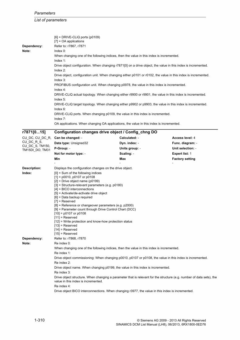
Parameters
List of parameters
1-310 © Siemens AG 2009 - 2013 All Rights ReservedSINAMICS DCM List Manual (LH8), 06/2013, 6RX1800-0ED76
[6] = DRIVE-CLiQ ports (p0109)[7] = OA applications
Dependency: Refer to: r7867, r7871
Note: Index 0:
When changing one of the following indices, then the value in this index is incremented.
Index 1:
Drive object configuration. When changing r7871[0] on a drive object, the value in this index is incremented.
Index 2:
Drive object, configuration unit. When changing either p0101 or r0102, the value in this index is incremented.
Index 3:
PROFIBUS configuration unit. When changing p0978, the value in this index is incremented.
Index 4:
DRIVE-CLiQ actual topology. When changing either r9900 or r9901, the value in this index is incremented.
Index 5:
DRIVE-CLiQ target topology. When changing either p9902 or p9903, the value in this index is incremented.
Index 6:
DRIVE-CLiQ ports. When changing p0109, the value in this index is incremented.
Index 7:
OA applications. When changing OA applications, the value in this index is incremented.
Description: Displays the configuration changes on the drive object.
Index: [0] = Sum of the following indices[1] = p0010, p0107 or p0108[2] = Drive object name (p0199)[3] = Structure-relevant parameters (e.g. p0180)[4] = BICO interconnections[5] = Activate/de-activate drive object[6] = Data backup required[7] = Reserved[8] = Reference or changeover parameters (e.g. p2000)[9] = Parameter count through Drive Control Chart (DCC)[10] = p0107 or p0108[11] = Reserved[12] = Write protection and know-how protection status[13] = Reserved[14] = Reserved[15] = Reserved
Dependency: Refer to: r7868, r7870
Note: Re index 0:
When changing one of the following indices, then the value in this index is incremented.
Re index 1:
Drive object commissioning: When changing p0010, p0107 or p0108, the value in this index is incremented.
Re index 2:
Drive object name. When changing p0199, the value in this index is incremented.
Re index 3:
Drive object structure. When changing a parameter that is relevant for the structure (e.g. number of data sets), the value in this index is incremented.
Re index 4:
Drive object BICO interconnections. When changing r3977, the value in this index is incremented.
r7871[0...15] Configuration changes drive object / Config_chng DOCU_DC, CU_DC_R, CU_DC_R_S, CU_DC_S, TM150, TM15DI_DO, TM31
Can be changed: - Calculated: - Access level: 4
Data type: Unsigned32 Dyn. index: - Func. diagram: -
P-Group: - Units group: - Unit selection: -
Not for motor type: - Scaling: - Expert list: 1
Min Max Factory setting - - -

List of parameters
Parameters
1-311© Siemens AG 2009 - 2013 All Rights ReservedSINAMICS DCM List Manual (LH8), 06/2013, 6RX1800-0ED76
Re index 5:
Drive object activity: When changing p0105, the value in this index is incremented.
Re index 6:
Drive object, data save.
0: There are no parameter changes to save.
1: There are parameter changes to save.
Re index 8:
Drive object changeover of units. When changing reference or changeover parameters (e.g. p2000, p0304), the value in this index is incremented.
Re index 9:
Drive object parameter count. When changing the number of parameters by loading Drive Control Chart (DCC), the value in this index is incremented.
Re index 10:
Drive object configuration. When changing either p0107 or p0108, the value in this index is incremented.
Re index 12:
Drive object configuration. When activating/deactivating write protection or know-how protection, the value in this index is incremented.
Description: Displays the configuration changes on the drive object.
Index: [0] = Sum of the following indices[1] = p0010, p0107 or p0108[2] = Drive object name (p0199)[3] = Structure-relevant parameters (e.g. p0180)[4] = BICO interconnections[5] = Activate/de-activate drive object[6] = Data backup required[7] = Activate/de-activate component[8] = Reference or changeover parameters (e.g. p2000)[9] = Parameter count through Drive Control Chart (DCC)[10] = p0107 or p0108[11] = Reserved[12] = Write protection and know-how protection status[13] = Reserved[14] = Reserved[15] = Enc type (p0400)
Dependency: Refer to: r7868, r7870
Note: Re index 0:
When changing one of the following indices, then the value in this index is incremented.
Re index 1:
Drive object commissioning: When changing p0010, p0107 or p0108, the value in this index is incremented.
Re index 2:
Drive object name. When changing p0199, the value in this index is incremented.
Re index 3:
Drive object structure. When changing a parameter that is relevant for the structure (e.g. number of data sets), the value in this index is incremented.
Re index 4:
Drive object BICO interconnections. When changing r3977, the value in this index is incremented.
Re index 5:
Drive object activity: When changing p0105, the value in this index is incremented.
r7871[0...15] Configuration changes drive object / Config_chng DODC_CTRL, DC_CTRL_R, DC_CTRL_R_S, DC_CTRL_S
Can be changed: - Calculated: - Access level: 4
Data type: Unsigned32 Dyn. index: - Func. diagram: -
P-Group: - Units group: - Unit selection: -
Not for motor type: - Scaling: - Expert list: 1
Min Max Factory setting - - -
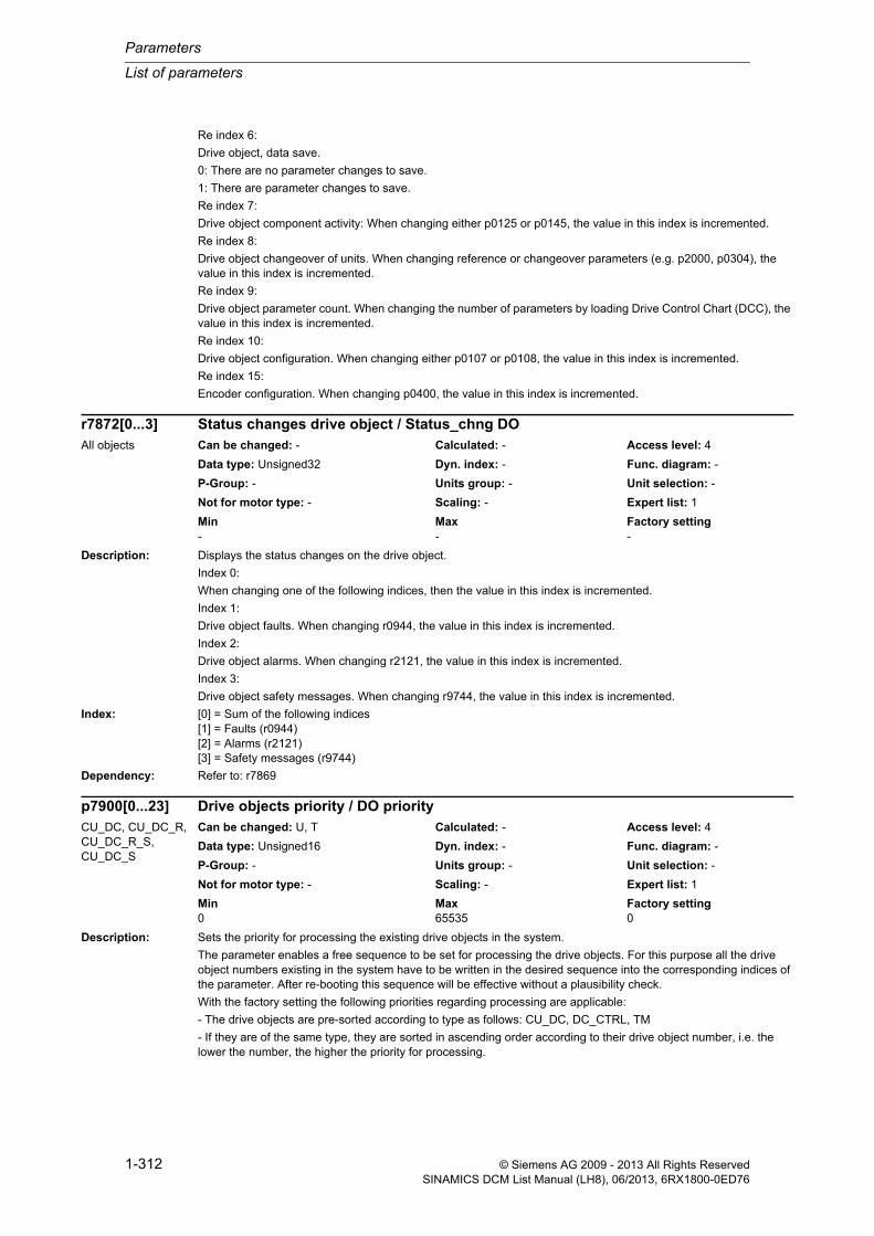
Parameters
List of parameters
1-312 © Siemens AG 2009 - 2013 All Rights ReservedSINAMICS DCM List Manual (LH8), 06/2013, 6RX1800-0ED76
Re index 6:
Drive object, data save.
0: There are no parameter changes to save.
1: There are parameter changes to save.
Re index 7:
Drive object component activity: When changing either p0125 or p0145, the value in this index is incremented.
Re index 8:
Drive object changeover of units. When changing reference or changeover parameters (e.g. p2000, p0304), the value in this index is incremented.
Re index 9:
Drive object parameter count. When changing the number of parameters by loading Drive Control Chart (DCC), the value in this index is incremented.
Re index 10:
Drive object configuration. When changing either p0107 or p0108, the value in this index is incremented.
Re index 15:
Encoder configuration. When changing p0400, the value in this index is incremented.
Description: Displays the status changes on the drive object.
Index 0:
When changing one of the following indices, then the value in this index is incremented.
Index 1:
Drive object faults. When changing r0944, the value in this index is incremented.
Index 2:
Drive object alarms. When changing r2121, the value in this index is incremented.
Index 3:
Drive object safety messages. When changing r9744, the value in this index is incremented.
Index: [0] = Sum of the following indices[1] = Faults (r0944)[2] = Alarms (r2121)[3] = Safety messages (r9744)
Dependency: Refer to: r7869
Description: Sets the priority for processing the existing drive objects in the system.
The parameter enables a free sequence to be set for processing the drive objects. For this purpose all the drive object numbers existing in the system have to be written in the desired sequence into the corresponding indices of the parameter. After re-booting this sequence will be effective without a plausibility check.
With the factory setting the following priorities regarding processing are applicable:
- The drive objects are pre-sorted according to type as follows: CU_DC, DC_CTRL, TM
- If they are of the same type, they are sorted in ascending order according to their drive object number, i.e. the lower the number, the higher the priority for processing.
r7872[0...3] Status changes drive object / Status_chng DOAll objects Can be changed: - Calculated: - Access level: 4
Data type: Unsigned32 Dyn. index: - Func. diagram: -
P-Group: - Units group: - Unit selection: -
Not for motor type: - Scaling: - Expert list: 1
Min Max Factory setting - - -
p7900[0...23] Drive objects priority / DO priorityCU_DC, CU_DC_R, CU_DC_R_S, CU_DC_S
Can be changed: U, T Calculated: - Access level: 4
Data type: Unsigned16 Dyn. index: - Func. diagram: -
P-Group: - Units group: - Unit selection: -
Not for motor type: - Scaling: - Expert list: 1
Min Max Factory setting 0 65535 0

List of parameters
Parameters
1-313© Siemens AG 2009 - 2013 All Rights ReservedSINAMICS DCM List Manual (LH8), 06/2013, 6RX1800-0ED76
Index: [0] = Drive object number Control Unit[1] = Drive object number object 1[2] = Drive object number object 2[3] = Drive object number object 3[4] = Drive object number object 4[5] = Drive object number object 5[6] = Drive object number object 6[7] = Drive object number object 7[8] = Drive object number object 8[9] = Drive object number object 9[10] = Drive object number object 10[11] = Drive object number object 11[12] = Drive object number object 12[13] = Drive object number object 13[14] = Drive object number object 14[15] = Drive object number object 15[16] = Drive object number object 16[17] = Drive object number object 17[18] = Drive object number object 18[19] = Drive object number object 19[20] = Drive object number object 20[21] = Drive object number object 21[22] = Drive object number object 22[23] = Drive object number object 23
Notice: This parameter may only be used by qualified service personnel.
Note: If the same drive object numbers are used and if the existing drive object numbers in the system are entered incom-pletely, the content of this parameter is ignored entirely. The behavior as with factory setting will then become effec-tive.
Description: Displays the sampling times currently present on the drive unit.
For r7901[x] = 0, the following applies:
The time slice is not active.
Description: Displays the number of hardware sampling times that can still be assigned.
These free sampling times can be used by OA applications such as DCC (Drive Control Chart) or FBLOCKS (free function blocks).
Note: OA: Open Architecture
r7901[0...75] Sampling times / t_sampleCU_DC, CU_DC_R, CU_DC_R_S, CU_DC_S
Can be changed: - Calculated: - Access level: 4
Data type: FloatingPoint32 Dyn. index: - Func. diagram: -
P-Group: - Units group: - Unit selection: -
Not for motor type: - Scaling: - Expert list: 1
Min Max Factory setting - [µs] - [µs] - [µs]
r7903 Hardware sampling times still assignable / HW t_samp freeCU_DC, CU_DC_R, CU_DC_R_S, CU_DC_S
Can be changed: - Calculated: - Access level: 3
Data type: Unsigned16 Dyn. index: - Func. diagram: -
P-Group: - Units group: - Unit selection: -
Not for motor type: - Scaling: - Expert list: 1
Min Max Factory setting - - -
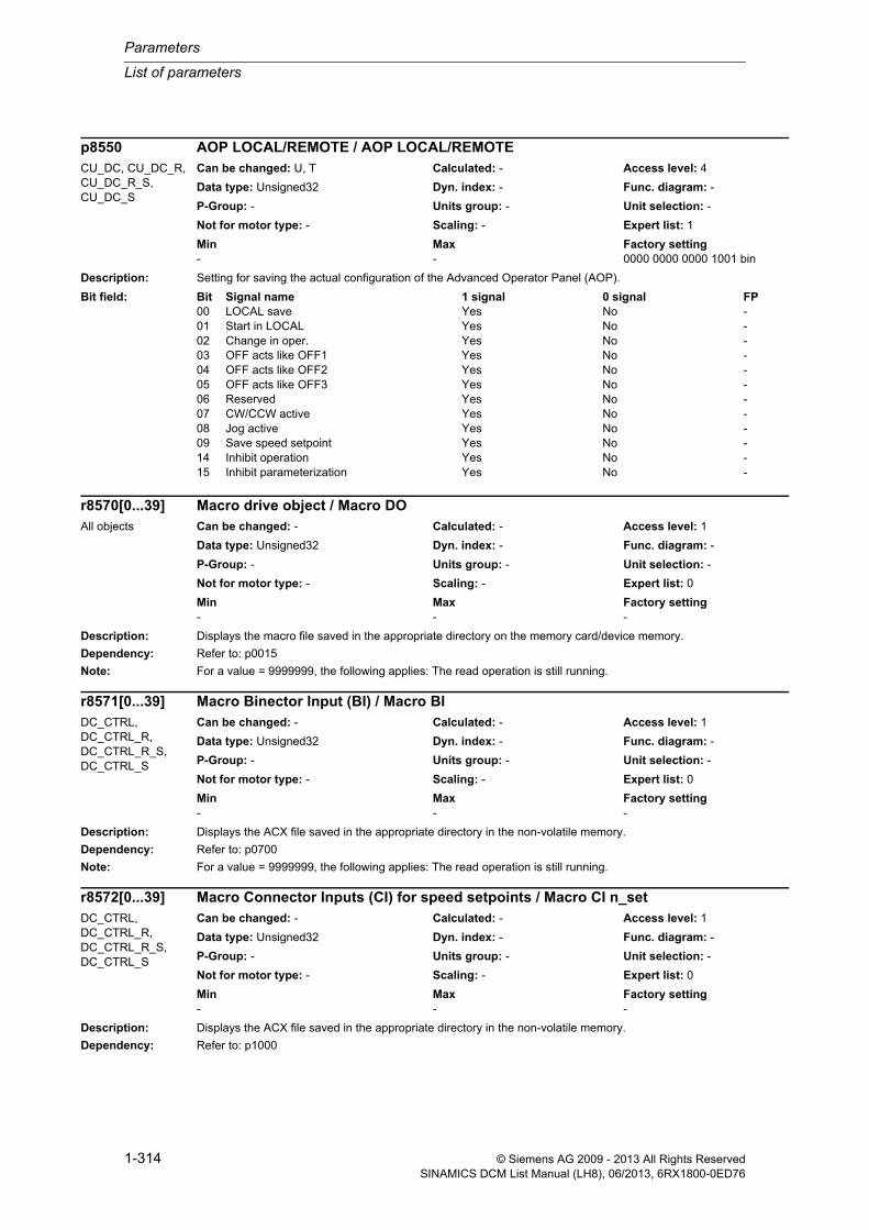
Parameters
List of parameters
1-314 © Siemens AG 2009 - 2013 All Rights ReservedSINAMICS DCM List Manual (LH8), 06/2013, 6RX1800-0ED76
Description: Setting for saving the actual configuration of the Advanced Operator Panel (AOP).
Description: Displays the macro file saved in the appropriate directory on the memory card/device memory.
Dependency: Refer to: p0015
Note: For a value = 9999999, the following applies: The read operation is still running.
Description: Displays the ACX file saved in the appropriate directory in the non-volatile memory.
Dependency: Refer to: p0700
Note: For a value = 9999999, the following applies: The read operation is still running.
Description: Displays the ACX file saved in the appropriate directory in the non-volatile memory.
Dependency: Refer to: p1000
p8550 AOP LOCAL/REMOTE / AOP LOCAL/REMOTECU_DC, CU_DC_R, CU_DC_R_S, CU_DC_S
Can be changed: U, T Calculated: - Access level: 4
Data type: Unsigned32 Dyn. index: - Func. diagram: -
P-Group: - Units group: - Unit selection: -
Not for motor type: - Scaling: - Expert list: 1
Min Max Factory setting - - 0000 0000 0000 1001 bin
Bit field: Bit Signal name 1 signal 0 signal FP00 LOCAL save Yes No -01 Start in LOCAL Yes No -02 Change in oper. Yes No -03 OFF acts like OFF1 Yes No -04 OFF acts like OFF2 Yes No -05 OFF acts like OFF3 Yes No -06 Reserved Yes No -07 CW/CCW active Yes No -08 Jog active Yes No -09 Save speed setpoint Yes No -14 Inhibit operation Yes No -15 Inhibit parameterization Yes No -
r8570[0...39] Macro drive object / Macro DOAll objects Can be changed: - Calculated: - Access level: 1
Data type: Unsigned32 Dyn. index: - Func. diagram: -
P-Group: - Units group: - Unit selection: -
Not for motor type: - Scaling: - Expert list: 0
Min Max Factory setting - - -
r8571[0...39] Macro Binector Input (BI) / Macro BIDC_CTRL, DC_CTRL_R, DC_CTRL_R_S, DC_CTRL_S
Can be changed: - Calculated: - Access level: 1
Data type: Unsigned32 Dyn. index: - Func. diagram: -
P-Group: - Units group: - Unit selection: -
Not for motor type: - Scaling: - Expert list: 0
Min Max Factory setting - - -
r8572[0...39] Macro Connector Inputs (CI) for speed setpoints / Macro CI n_setDC_CTRL, DC_CTRL_R, DC_CTRL_R_S, DC_CTRL_S
Can be changed: - Calculated: - Access level: 1
Data type: Unsigned32 Dyn. index: - Func. diagram: -
P-Group: - Units group: - Unit selection: -
Not for motor type: - Scaling: - Expert list: 0
Min Max Factory setting - - -

List of parameters
Parameters
1-315© Siemens AG 2009 - 2013 All Rights ReservedSINAMICS DCM List Manual (LH8), 06/2013, 6RX1800-0ED76
Note: For a value = 9999999, the following applies: The read operation is still running.
Description: Displays the ACX file saved in the appropriate directory in the non-volatile memory.
Dependency: Refer to: p1500
Note: For a value = 9999999, the following applies: The read operation is still running.
Description: Displays the macro currently being executed on the drive object.
Dependency: Refer to: p0015, p0700, p1000, p1500, r8570, r8571, r8572, r8573
Description: Project selection for SINAMICS Link.
Value: 16: SINAMICS Link project 16 participants64: SINAMICS Link project 64 participants
Note: SINAMICS Link requires that the appropriate CBE20 firmware version is selected (p8835 = 3).
The parameter must be set the same for all participants.
A change only becomes effective after a POWER ON.
The parameter is not influenced by setting the factory setting.
Description: Sets the clock cycle for SINAMICS Link.
r8573[0...39] Macro Connector Inputs (CI) for torque setpoints / Macro CI M_setDC_CTRL, DC_CTRL_R, DC_CTRL_R_S, DC_CTRL_S
Can be changed: - Calculated: - Access level: 1
Data type: Unsigned32 Dyn. index: - Func. diagram: -
P-Group: - Units group: - Unit selection: -
Not for motor type: - Scaling: - Expert list: 0
Min Max Factory setting - - -
r8585 Macro execution actual / Macro executedAll objects Can be changed: - Calculated: - Access level: 1
Data type: Unsigned16 Dyn. index: - Func. diagram: -
P-Group: - Units group: - Unit selection: -
Not for motor type: - Scaling: - Expert list: 0
Min Max Factory setting - - -
p8811 SINAMICS Link project selection / SINAMICS Link projCU_DC (PROFINET), CU_DC_R (PROFINET), CU_DC_R_S (PROFINET), CU_DC_S (PROFINET)
Can be changed: C1(1) Calculated: - Access level: 3
Data type: Integer16 Dyn. index: - Func. diagram: -
P-Group: Communications Units group: - Unit selection: -
Not for motor type: - Scaling: - Expert list: 1
Min Max Factory setting 16 64 64
p8812[0...1] SINAMICS Link settings / SINAMICS Link cl cCU_DC (PROFINET), CU_DC_R (PROFINET), CU_DC_R_S (PROFINET), CU_DC_S (PROFINET)
Can be changed: C1(1) Calculated: - Access level: 3
Data type: Unsigned16 Dyn. index: - Func. diagram: -
P-Group: Communications Units group: - Unit selection: -
Not for motor type: - Scaling: - Expert list: 1
Min Max Factory setting 0 2000 [0] 0
[1] 2000

Parameters
List of parameters
1-316 © Siemens AG 2009 - 2013 All Rights ReservedSINAMICS DCM List Manual (LH8), 06/2013, 6RX1800-0ED76
Re index 0:
0 = clock synchronous mode not activated, 1 = clock synchronous mode activated
Re index 1:
Possible values: 500, 1000, 2000 µs
Index: [0] = Activate isochronous mode[1] = Bus CC [µs]
Dependency: Refer to: p8811
Note: SINAMICS Link requires that the appropriate CBE20 firmware version is selected (p8835 = 3).
A change only becomes effective after a POWER ON.
The parameter is not influenced by setting the factory setting.
Re index 0:
Is applicable for the synchronization of the application. The SINAMICS Link itself is always synchronous.
Re index 1:
The value must be set the same for all participants.
When newly selecting the project p8811, p8812[1] is set to the factory setting.
For p8811 = 16, the following applies:
Min/max/factory setting: 500/500/500 µs
For p8811 = 64, the following applies:
Min/max/factory setting: 1000/2000/2000 µs
Description: Sets the number of remote controllers expected for PROFINET CBE20.
The "Shared Device" functionality is activated with a value = 2.
The drive is being accessed by two PROFINET controllers simultaneously:
- automation controller (SIMOTION or SIMATIC A-CPU).
- safety controller (SIMATIC F-CPU).
Value: 1: Automation or Safety2: Automation and Safety
Notice: The F CPU may only use PROFIsafe telegrams.
The A CPU must be connected to enable the F CPU to gain access.
Set the value = 1 to commission the F CPU individually.
Note: A change only becomes effective after a POWER ON.
Description: Selects the firmware version for the CBE20.
p8829 CBE20 remote controller number / CBE20 rem ctrl numCU_DC (PROFINET), CU_DC_R (PROFINET), CU_DC_R_S (PROFINET), CU_DC_S (PROFINET)
Can be changed: C1(1) Calculated: - Access level: 3
Data type: Integer16 Dyn. index: - Func. diagram: -
P-Group: Communications Units group: - Unit selection: -
Not for motor type: - Scaling: - Expert list: 1
Min Max Factory setting 1 2 1
p8835 CBE20 firmware selection / CBE20 FW selCU_DC (PROFINET), CU_DC_R (PROFINET), CU_DC_R_S (PROFINET), CU_DC_S (PROFINET)
Can be changed: C1(1) Calculated: - Access level: 3
Data type: Integer16 Dyn. index: - Func. diagram: -
P-Group: Communications Units group: - Unit selection: -
Not for motor type: - Scaling: - Expert list: 1
Min Max Factory setting 1 99 1

List of parameters
Parameters
1-317© Siemens AG 2009 - 2013 All Rights ReservedSINAMICS DCM List Manual (LH8), 06/2013, 6RX1800-0ED76
Value: 1: PROFINET Device3: SINAMICS Link4: Ethernet/IP99: Customer-specific from the OEM directory
Note: A change only becomes effective after a POWER ON.
The parameter is not influenced by setting the factory setting.
CBE20: Communication Board Ethernet 20
Description: Selects the node address for the SINAMICS Link on the Communication Board Ethernet 20 (CBE20).
p8836 = 0: SINAMICS Link de-activated
p8836 = 1 ... 64: SINAMICS Link node address
Dependency: Refer to: p8835
Note: SINAMICS Link requires that the appropriate CBE20 firmware version is selected (p8835 = 3).
A change only becomes effective after a POWER ON.
The parameter is not influenced by setting the factory setting.
Description: Sets the processing mode for PROFIdrive STW1.10 "master control by PLC".
Generally, control world 1 is received with the first receive word (PZD1) (this is in conformance to the PROFIdrive profile). The behavior of STW1.10 = 0 corresponds to that of the PROFIdrive profile. For other applications that deviate from this, the behavior can be adapted using this particular parameter.
Value: 0: Freeze setpoints and continue to process sign-of-life1: Freeze setpoints and sign-of-life2: Do not freeze setpoints
Recommend.: Do not change the setting p2037 = 0.
Note: If the STW1 is not transferred according to the PROFIdrive with PZD1 (with bit 10 "master control by PLC"), then p2037 should be set to 2.
Description: Assignment of the hardware for cyclic communications via PZD interface 1 (IF1) and interface 2 (IF2).
p8836 SINAMICS Link address / SINAMICS Link addCU_DC (PROFINET), CU_DC_R (PROFINET), CU_DC_R_S (PROFINET), CU_DC_S (PROFINET)
Can be changed: C1(1) Calculated: - Access level: 3
Data type: Unsigned16 Dyn. index: - Func. diagram: -
P-Group: Communications Units group: - Unit selection: -
Not for motor type: - Scaling: - Expert list: 1
Min Max Factory setting 0 64 0
p8837 IF2 STW1.10 = 0 mode / IF2 STW1.10=0DC_CTRL, DC_CTRL_R, DC_CTRL_R_S, DC_CTRL_S
Can be changed: T Calculated: - Access level: 3
Data type: Integer16 Dyn. index: - Func. diagram: -
P-Group: Communications Units group: - Unit selection: -
Not for motor type: - Scaling: - Expert list: 1
Min Max Factory setting 0 2 2
p8839[0...1] PZD interface hardware assignment / PZD IF HW assignCU_DC, CU_DC_R, CU_DC_R_S, CU_DC_S
Can be changed: C1(1) Calculated: - Access level: 3
Data type: Integer16 Dyn. index: - Func. diagram: -
P-Group: Communications Units group: - Unit selection: -
Not for motor type: - Scaling: - Expert list: 1
Min Max Factory setting 0 99 99

Parameters
List of parameters
1-318 © Siemens AG 2009 - 2013 All Rights ReservedSINAMICS DCM List Manual (LH8), 06/2013, 6RX1800-0ED76
Value: 0: Inactive 1: Control Unit onboard2: COMM BOARD99: Automatic
Index: [0] = Interface 1[1] = Interface 2
Dependency: Refer to: p2030
Note: For value = 99 (automatic) the following applies:
- if a COMM BOARD is not inserted, then the integrated communication interface (PROFIBUS/USS) communicates via IF1.
- if a CBE20 is inserted, then PROFINET CBE20 communicates via IF1 and PROFIBUS/USS via IF2.
For a value not equal to 99 (automatic) the following applies:
- both indices must be set to a number not equal to 99 (automatic).
A new setting only becomes effective after POWER ON, reset or download.
Description: Sets the monitoring time to monitor the process data received via COMM BOARD.
If, during this time, the Control Unit does not receive any process data from the COMM BOARD, then an appropri-ate message is output.
Note: This monitoring function only monitors the connection between the Control Unit and COMM BOARD and not the data traffic on the fieldbus.
Value = 0: Monitoring is de-activated.
Description: Sets the send configuration data for the COMM BOARD.
The setting is activated with p8842.
Dependency: Refer to: p8842
Note: The configuration data are specific to the inserted COMM BOARD.
For CBE20, the configuration data are not relevant.
p8840 COMM BOARD monitoring time / CB t_monitCU_DC (PROFINET), CU_DC_R (PROFINET), CU_DC_R_S (PROFINET), CU_DC_S (PROFINET)
Can be changed: U, T Calculated: - Access level: 3
Data type: FloatingPoint32 Dyn. index: - Func. diagram: -
P-Group: Communications Units group: - Unit selection: -
Not for motor type: - Scaling: - Expert list: 1
Min Max Factory setting 0 [ms] 65535000 [ms] 20 [ms]
p8841[0...239] COMM BOARD send configuration data / CB s config_datCU_DC (PROFINET), CU_DC_R (PROFINET), CU_DC_R_S (PROFINET), CU_DC_S (PROFINET)
Can be changed: U, T Calculated: - Access level: 3
Data type: Unsigned16 Dyn. index: - Func. diagram: -
P-Group: Communications Units group: - Unit selection: -
Not for motor type: - Scaling: - Expert list: 1
Min Max Factory setting 0 65535 0

List of parameters
Parameters
1-319© Siemens AG 2009 - 2013 All Rights ReservedSINAMICS DCM List Manual (LH8), 06/2013, 6RX1800-0ED76
Description: Activate a modified send configuration for COMM BOARD.
With p8842 = 1, the values in p8841 are transferred to the COMM BOARD and activated. After this, p8842 is auto-matically set to zero.
Dependency: Refer to: p8841
Note: For CBE20, certain SINAMICS parameters are newly evaluated and activated. An existing, cyclic bus connection is interrupted.
Description: Displays the PROFIdrive PZD state.
Dependency: Refer to: p2044
Note: When using the "setpoint failure" signal, the bus can be monitored and an application-specific response triggered when the setpoint fails.
Description: Sets the delay time to initiate fault F01910 after a setpoint failure.
The time until the fault is initiated can be used by the application. This means that is is possible to respond to the failure while the drive is still operational (e.g. emergency retraction).
Dependency: Refer to: r2043
Description: Sets the sampling time for the cyclic interface 2 (IF2).
p8842 Activate COMM BOARD send configuration / CB s config actCU_DC (PROFINET), CU_DC_R (PROFINET), CU_DC_R_S (PROFINET), CU_DC_S (PROFINET)
Can be changed: U, T Calculated: - Access level: 3
Data type: Unsigned16 Dyn. index: - Func. diagram: -
P-Group: Communications Units group: - Unit selection: -
Not for motor type: - Scaling: - Expert list: 1
Min Max Factory setting 0 1 0
r8843.0...2 BO: IF2 PZD state / IF2 PZD stateCU_DC, CU_DC_R, CU_DC_R_S, CU_DC_S
Can be changed: - Calculated: - Access level: 3
Data type: Unsigned8 Dyn. index: - Func. diagram: 2410
P-Group: Communications Units group: - Unit selection: -
Not for motor type: - Scaling: - Expert list: 1
Min Max Factory setting - - -
Bit field: Bit Signal name 1 signal 0 signal FP00 Setpoint failure Yes No -02 Fieldbus oper Yes No -
p8844 IF2 fault delay / IF2 F delayDC_CTRL, DC_CTRL_R, DC_CTRL_R_S, DC_CTRL_S
Can be changed: U, T Calculated: - Access level: 3
Data type: FloatingPoint32 Dyn. index: - Func. diagram: 2410
P-Group: Communications Units group: - Unit selection: -
Not for motor type: - Scaling: - Expert list: 1
Min Max Factory setting 0 [s] 100 [s] 0 [s]
p8848 IF2 PZD sampling time / IF2 PZD t_sampleCU_DC, CU_DC_R, CU_DC_R_S, CU_DC_S
Can be changed: C1(3) Calculated: - Access level: 3
Data type: FloatingPoint32 Dyn. index: - Func. diagram: -
P-Group: Communications Units group: - Unit selection: -
Not for motor type: - Scaling: - Expert list: 1
Min Max Factory setting 1.00 [ms] 16.00 [ms] 4.00 [ms]

Parameters
List of parameters
1-320 © Siemens AG 2009 - 2013 All Rights ReservedSINAMICS DCM List Manual (LH8), 06/2013, 6RX1800-0ED76
Note: The system only permits certain sampling times and after writing to this parameter, displays the value that has actu-ally been set.
For clock cycle synchronous operation, the specified bus cycle time applies (Tdp).
Description: Displays the receive configuration data for the COMM BOARD.
Description: Connector output for interconnecting the PZD (setpoints) received via interface 2 in the word format.
Index: [0] = PZD 1[1] = PZD 2[2] = PZD 3[3] = PZD 4[4] = PZD 5[5] = PZD 6[6] = PZD 7[7] = PZD 8[8] = PZD 9[9] = PZD 10[10] = PZD 11[11] = PZD 12[12] = PZD 13[13] = PZD 14[14] = PZD 15[15] = PZD 16[16] = PZD 17[17] = PZD 18[18] = PZD 19[19] = PZD 20[20] = PZD 21[21] = PZD 22[22] = PZD 23[23] = PZD 24[24] = PZD 25[25] = PZD 26[26] = PZD 27[27] = PZD 28[28] = PZD 29[29] = PZD 30[30] = PZD 31[31] = PZD 32[32] = PZD 33[33] = PZD 34
r8849[0...139] COMM BOARD receive configuration data / CB r config_datCU_DC (PROFINET), CU_DC_R (PROFINET), CU_DC_R_S (PROFINET), CU_DC_S (PROFINET)
Can be changed: - Calculated: - Access level: 3
Data type: Unsigned16 Dyn. index: - Func. diagram: -
P-Group: Communications Units group: - Unit selection: -
Not for motor type: - Scaling: - Expert list: 1
Min Max Factory setting - - -
r8850[0...63] CO: IF2 PZD receive word / IF2 PZD recv wordDC_CTRL, DC_CTRL_R, DC_CTRL_R_S, DC_CTRL_S
Can be changed: - Calculated: - Access level: 3
Data type: Integer16 Dyn. index: - Func. diagram: 2485, 9204, 9206
P-Group: Communications Units group: - Unit selection: -
Not for motor type: - Scaling: 4000H Expert list: 1
Min Max Factory setting - - -

List of parameters
Parameters
1-321© Siemens AG 2009 - 2013 All Rights ReservedSINAMICS DCM List Manual (LH8), 06/2013, 6RX1800-0ED76
[34] = PZD 35[35] = PZD 36[36] = PZD 37[37] = PZD 38[38] = PZD 39[39] = PZD 40[40] = PZD 41[41] = PZD 42[42] = PZD 43[43] = PZD 44[44] = PZD 45[45] = PZD 46[46] = PZD 47[47] = PZD 48[48] = PZD 49[49] = PZD 50[50] = PZD 51[51] = PZD 52[52] = PZD 53[53] = PZD 54[54] = PZD 55[55] = PZD 56[56] = PZD 57[57] = PZD 58[58] = PZD 59[59] = PZD 60[60] = PZD 61[61] = PZD 62[62] = PZD 63[63] = PZD 64
Dependency: Refer to: r8860, r8890, r8891, r8892, r8893
Notice: Where there is a multiple interconnection of a connector output, all the connector inputs must either have Integer or FloatingPoint data types.
A BICO interconnection for a single PZD can only take place either on r8850 or r8860.
Note: IF2: Interface 2
PZD1 to PZD4 are displayed bit-serially in r8890 to r8893.
Description: Connector output for interconnecting the PZD (setpoints) received via interface 2 in the word format.
Index: [0] = PZD 1[1] = PZD 2[2] = PZD 3[3] = PZD 4[4] = PZD 5
Note: IF2: Interface 2
PZD1 to PZD2 are displayed bit-serially in r8890 to r8891.
r8850[0...4] CO: IF2 PZD receive word / IF2 PZD recv wordTM150, TM15DI_DO, TM31
Can be changed: - Calculated: - Access level: 3
Data type: Integer16 Dyn. index: - Func. diagram: 2491
P-Group: Communications Units group: - Unit selection: -
Not for motor type: - Scaling: 4000H Expert list: 1
Min Max Factory setting - - -

Parameters
List of parameters
1-322 © Siemens AG 2009 - 2013 All Rights ReservedSINAMICS DCM List Manual (LH8), 06/2013, 6RX1800-0ED76
Description: Selects the PZD (actual values) to be sent via interface 2 in the word format.
Index: [0] = PZD 1[1] = PZD 2[2] = PZD 3[3] = PZD 4[4] = PZD 5[5] = PZD 6[6] = PZD 7[7] = PZD 8[8] = PZD 9[9] = PZD 10[10] = PZD 11[11] = PZD 12[12] = PZD 13[13] = PZD 14[14] = PZD 15[15] = PZD 16[16] = PZD 17[17] = PZD 18[18] = PZD 19[19] = PZD 20[20] = PZD 21[21] = PZD 22[22] = PZD 23[23] = PZD 24[24] = PZD 25[25] = PZD 26[26] = PZD 27[27] = PZD 28[28] = PZD 29[29] = PZD 30[30] = PZD 31[31] = PZD 32[32] = PZD 33[33] = PZD 34[34] = PZD 35[35] = PZD 36[36] = PZD 37[37] = PZD 38[38] = PZD 39[39] = PZD 40[40] = PZD 41[41] = PZD 42[42] = PZD 43[43] = PZD 44[44] = PZD 45[45] = PZD 46[46] = PZD 47[47] = PZD 48[48] = PZD 49[49] = PZD 50[50] = PZD 51[51] = PZD 52[52] = PZD 53
p8851[0...63] CI: IF2 PZD send word / IF2 PZD send wordDC_CTRL, DC_CTRL_R, DC_CTRL_R_S, DC_CTRL_S
Can be changed: U, T Calculated: - Access level: 3
Data type: Unsigned32 / Integer16 Dyn. index: - Func. diagram: 2487, 9208
P-Group: Communications Units group: - Unit selection: -
Not for motor type: - Scaling: 4000H Expert list: 1
Min Max Factory setting - - 0

List of parameters
Parameters
1-323© Siemens AG 2009 - 2013 All Rights ReservedSINAMICS DCM List Manual (LH8), 06/2013, 6RX1800-0ED76
[53] = PZD 54[54] = PZD 55[55] = PZD 56[56] = PZD 57[57] = PZD 58[58] = PZD 59[59] = PZD 60[60] = PZD 61[61] = PZD 62[62] = PZD 63[63] = PZD 64
Dependency: Refer to: p8861
Note: IF2: Interface 2
Description: Selects the PZD (actual values) to be sent via interface 2 in the word format.
Index: [0] = PZD 1[1] = PZD 2[2] = PZD 3[3] = PZD 4[4] = PZD 5
Note: IF2: Interface 2
Description: Displays the sent PZD (actual values) sent via interface 2.
Index: [0] = PZD 1[1] = PZD 2[2] = PZD 3[3] = PZD 4[4] = PZD 5[5] = PZD 6[6] = PZD 7[7] = PZD 8[8] = PZD 9[9] = PZD 10[10] = PZD 11[11] = PZD 12[12] = PZD 13[13] = PZD 14[14] = PZD 15[15] = PZD 16[16] = PZD 17[17] = PZD 18[18] = PZD 19[19] = PZD 20[20] = PZD 21
p8851[0...4] CI: IF2 PZD send word / IF2 PZD send wordTM150, TM15DI_DO, TM31
Can be changed: U, T Calculated: - Access level: 3
Data type: Unsigned32 / Integer16 Dyn. index: - Func. diagram: 2493, 9210
P-Group: Communications Units group: - Unit selection: -
Not for motor type: - Scaling: 4000H Expert list: 1
Min Max Factory setting - - 0
r8853[0...63] IF2 diagnostics PZD send / IF2 diag PZD sendDC_CTRL, DC_CTRL_R, DC_CTRL_R_S, DC_CTRL_S
Can be changed: - Calculated: - Access level: 3
Data type: Unsigned16 Dyn. index: - Func. diagram: 2487, 9208, 9210
P-Group: Communications Units group: - Unit selection: -
Not for motor type: - Scaling: - Expert list: 1
Min Max Factory setting - - -

Parameters
List of parameters
1-324 © Siemens AG 2009 - 2013 All Rights ReservedSINAMICS DCM List Manual (LH8), 06/2013, 6RX1800-0ED76
[21] = PZD 22[22] = PZD 23[23] = PZD 24[24] = PZD 25[25] = PZD 26[26] = PZD 27[27] = PZD 28[28] = PZD 29[29] = PZD 30[30] = PZD 31[31] = PZD 32[32] = PZD 33[33] = PZD 34[34] = PZD 35[35] = PZD 36[36] = PZD 37[37] = PZD 38[38] = PZD 39[39] = PZD 40[40] = PZD 41[41] = PZD 42[42] = PZD 43[43] = PZD 44[44] = PZD 45[45] = PZD 46[46] = PZD 47[47] = PZD 48[48] = PZD 49[49] = PZD 50[50] = PZD 51[51] = PZD 52[52] = PZD 53[53] = PZD 54[54] = PZD 55[55] = PZD 56[56] = PZD 57[57] = PZD 58[58] = PZD 59[59] = PZD 60[60] = PZD 61[61] = PZD 62[62] = PZD 63[63] = PZD 64
Dependency: Refer to: p8851, p8861
Note: IF2: Interface 2
Bit field: Bit Signal name 1 signal 0 signal FP00 Bit 0 ON OFF -01 Bit 1 ON OFF -02 Bit 2 ON OFF -03 Bit 3 ON OFF -04 Bit 4 ON OFF -05 Bit 5 ON OFF -06 Bit 6 ON OFF -07 Bit 7 ON OFF -08 Bit 8 ON OFF -09 Bit 9 ON OFF -10 Bit 10 ON OFF -11 Bit 11 ON OFF -12 Bit 12 ON OFF -13 Bit 13 ON OFF -14 Bit 14 ON OFF -15 Bit 15 ON OFF -

List of parameters
Parameters
1-325© Siemens AG 2009 - 2013 All Rights ReservedSINAMICS DCM List Manual (LH8), 06/2013, 6RX1800-0ED76
Description: Displays the sent PZD (actual values) sent via interface 2.
Index: [0] = PZD 1[1] = PZD 2[2] = PZD 3[3] = PZD 4[4] = PZD 5
Note: IF2: Interface 2
Description: Status display for COMM BOARD.
Value: 0: No initialization1: Fatal fault2: Initialization3: Send configuration4: Receive configuration5: Non-cyclic communication6: Cyclic communications but no setpoints (stop/no clock cycle)255: Cyclic communication
r8853[0...4] IF2 diagnostics PZD send / IF2 diag PZD sendTM150, TM15DI_DO, TM31
Can be changed: - Calculated: - Access level: 3
Data type: Unsigned16 Dyn. index: - Func. diagram: 2493
P-Group: Communications Units group: - Unit selection: -
Not for motor type: - Scaling: - Expert list: 1
Min Max Factory setting - - -
Bit field: Bit Signal name 1 signal 0 signal FP00 Bit 0 ON OFF -01 Bit 1 ON OFF -02 Bit 2 ON OFF -03 Bit 3 ON OFF -04 Bit 4 ON OFF -05 Bit 5 ON OFF -06 Bit 6 ON OFF -07 Bit 7 ON OFF -08 Bit 8 ON OFF -09 Bit 9 ON OFF -10 Bit 10 ON OFF -11 Bit 11 ON OFF -12 Bit 12 ON OFF -13 Bit 13 ON OFF -14 Bit 14 ON OFF -15 Bit 15 ON OFF -
r8854 COMM BOARD state / CB stateCU_DC (PROFINET), CU_DC_R (PROFINET), CU_DC_R_S (PROFINET), CU_DC_S (PROFINET)
Can be changed: - Calculated: - Access level: 3
Data type: Integer16 Dyn. index: - Func. diagram: -
P-Group: Communications Units group: - Unit selection: -
Not for motor type: - Scaling: - Expert list: 1
Min Max Factory setting 0 255 -

Parameters
List of parameters
1-326 © Siemens AG 2009 - 2013 All Rights ReservedSINAMICS DCM List Manual (LH8), 06/2013, 6RX1800-0ED76
Description: Displays the COMM BOARD diagnostics data.
Note: The display depends on the COMM BOARD being used.
Example for CBE20:
r8858[0] = 4201 --> Siemens CBE20
r8858[1] = 1 --> firmware type = PROFINET device (see p8835)
r8858[2] = x --> state of cyclic communication
r8858[3] = y --> state of the IP configuration
r8858[4] = 1281 --> device ID 0501 hex = SINAMICS S120/S150
r8858[5 ... 39] --> only for internal Siemens diagnostics.
Description: Displays the COMM BOARD identification data
Index: [0] = Version interface structure[1] = Version interface driver[2] = Company (Siemens = 42)[3] = CB type[4] = Firmware version[5] = Firmware date (year)[6] = Firmware date (day/month)[7] = Firmware patch/hot fix
Note: Example for CBE20:
r8859[0] = 100 --> version of the interface structure V1.00
r8859[1] = 111 --> version of the interface driver V1.11
r8859[2] = 42 --> SIEMENS
r8859[3] = 0 --> CBE20
r8859[4] = 1200 --> first part, firmware version V12.00 (second part, see index 7)
r8859[5] = 2010 --> year 2010
r8859[6] = 2306 --> 23rd June
r8859[7] = 1300 --> second part, firmware version (complete version: V12.00.13.00)
r8858[0...39] COMM BOARD read diagnostics channel / CB diag_chan readCU_DC (PROFINET), CU_DC_R (PROFINET), CU_DC_R_S (PROFINET), CU_DC_S (PROFINET)
Can be changed: - Calculated: - Access level: 3
Data type: Unsigned16 Dyn. index: - Func. diagram: -
P-Group: Communications Units group: - Unit selection: -
Not for motor type: - Scaling: - Expert list: 1
Min Max Factory setting - - -
r8859[0...7] COMM BOARD identification data / CB ident dataCU_DC (PROFINET), CU_DC_R (PROFINET), CU_DC_R_S (PROFINET), CU_DC_S (PROFINET)
Can be changed: - Calculated: - Access level: 3
Data type: Unsigned16 Dyn. index: - Func. diagram: -
P-Group: Communications Units group: - Unit selection: -
Not for motor type: - Scaling: - Expert list: 1
Min Max Factory setting - - -
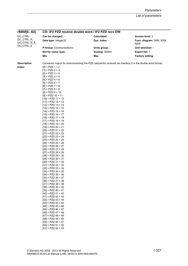
List of parameters
Parameters
1-327© Siemens AG 2009 - 2013 All Rights ReservedSINAMICS DCM List Manual (LH8), 06/2013, 6RX1800-0ED76
Description: Connector output for interconnecting the PZD (setpoints) received via interface 2 in the double word format.
Index: [0] = PZD 1 + 2[1] = PZD 2 + 3[2] = PZD 3 + 4[3] = PZD 4 + 5[4] = PZD 5 + 6[5] = PZD 6 + 7[6] = PZD 7 + 8[7] = PZD 8 + 9[8] = PZD 9 + 10[9] = PZD 10 + 11[10] = PZD 11 + 12[11] = PZD 12 + 13[12] = PZD 13 + 14[13] = PZD 14 + 15[14] = PZD 15 + 16[15] = PZD 16 + 17[16] = PZD 17 + 18[17] = PZD 18 + 19[18] = PZD 19 + 20[19] = PZD 20 + 21[20] = PZD 21 + 22[21] = PZD 22 + 23[22] = PZD 23 + 24[23] = PZD 24 + 25[24] = PZD 25 + 26[25] = PZD 26 + 27[26] = PZD 27 + 28[27] = PZD 28 + 29[28] = PZD 29 + 30[29] = PZD 30 + 31[30] = PZD 31 + 32[31] = PZD 32 + 33[32] = PZD 33 + 34[33] = PZD 34 + 35[34] = PZD 35 + 36[35] = PZD 36 + 37[36] = PZD 37 + 38[37] = PZD 38 + 39[38] = PZD 39 + 40[39] = PZD 40 + 41[40] = PZD 41 + 42[41] = PZD 42 + 43[42] = PZD 43 + 44[43] = PZD 44 + 45[44] = PZD 45 + 46[45] = PZD 46 + 47[46] = PZD 47 + 48[47] = PZD 48 + 49[48] = PZD 49 + 50[49] = PZD 50 + 51[50] = PZD 51 + 52[51] = PZD 52 + 53
r8860[0...62] CO: IF2 PZD receive double word / IF2 PZD recv DWDC_CTRL, DC_CTRL_R, DC_CTRL_R_S, DC_CTRL_S
Can be changed: - Calculated: - Access level: 3
Data type: Integer32 Dyn. index: - Func. diagram: 2485, 9204, 9206
P-Group: Communications Units group: - Unit selection: -
Not for motor type: - Scaling: 4000H Expert list: 1
Min Max Factory setting - - -

Parameters
List of parameters
1-328 © Siemens AG 2009 - 2013 All Rights ReservedSINAMICS DCM List Manual (LH8), 06/2013, 6RX1800-0ED76
[52] = PZD 53 + 54[53] = PZD 54 + 55[54] = PZD 55 + 56[55] = PZD 56 + 57[56] = PZD 57 + 58[57] = PZD 58 + 59[58] = PZD 59 + 60[59] = PZD 60 + 61[60] = PZD 61 + 62[61] = PZD 62 + 63[62] = PZD 63 + 64
Dependency: Refer to: r8850
Notice: Where there is a multiple interconnection of a connector output, all the connector inputs must either have Integer or FloatingPoint data types.
A BICO interconnection for a single PZD can only take place either on r8850 or r8860.
A maximum of 4 indices of the "trace" function can be used.
Note: IF2: Interface 2
Description: Selects the PZD (actual values) to be sent via interface 2 in the double word format.
Index: [0] = PZD 1 + 2[1] = PZD 2 + 3[2] = PZD 3 + 4[3] = PZD 4 + 5[4] = PZD 5 + 6[5] = PZD 6 + 7[6] = PZD 7 + 8[7] = PZD 8 + 9[8] = PZD 9 + 10[9] = PZD 10 + 11[10] = PZD 11 + 12[11] = PZD 12 + 13[12] = PZD 13 + 14[13] = PZD 14 + 15[14] = PZD 15 + 16[15] = PZD 16 + 17[16] = PZD 17 + 18[17] = PZD 18 + 19[18] = PZD 19 + 20[19] = PZD 20 + 21[20] = PZD 21 + 22[21] = PZD 22 + 23[22] = PZD 23 + 24[23] = PZD 24 + 25[24] = PZD 25 + 26[25] = PZD 26 + 27[26] = PZD 27 + 28[27] = PZD 28 + 29[28] = PZD 29 + 30[29] = PZD 30 + 31[30] = PZD 31 + 32[31] = PZD 32 + 33[32] = PZD 33 + 34
p8861[0...62] CI: IF2 PZD send double word / IF2 PZD send DWDC_CTRL, DC_CTRL_R, DC_CTRL_R_S, DC_CTRL_S
Can be changed: U, T Calculated: - Access level: 3
Data type: Unsigned32 / Integer32 Dyn. index: - Func. diagram: 2487, 9208, 9210
P-Group: Communications Units group: - Unit selection: -
Not for motor type: - Scaling: 4000H Expert list: 1
Min Max Factory setting - - 0

List of parameters
Parameters
1-329© Siemens AG 2009 - 2013 All Rights ReservedSINAMICS DCM List Manual (LH8), 06/2013, 6RX1800-0ED76
[33] = PZD 34 + 35[34] = PZD 35 + 36[35] = PZD 36 + 37[36] = PZD 37 + 38[37] = PZD 38 + 39[38] = PZD 39 + 40[39] = PZD 40 + 41[40] = PZD 41 + 42[41] = PZD 42 + 43[42] = PZD 43 + 44[43] = PZD 44 + 45[44] = PZD 45 + 46[45] = PZD 46 + 47[46] = PZD 47 + 48[47] = PZD 48 + 49[48] = PZD 49 + 50[49] = PZD 50 + 51[50] = PZD 51 + 52[51] = PZD 52 + 53[52] = PZD 53 + 54[53] = PZD 54 + 55[54] = PZD 55 + 56[55] = PZD 56 + 57[56] = PZD 57 + 58[57] = PZD 58 + 59[58] = PZD 59 + 60[59] = PZD 60 + 61[60] = PZD 61 + 62[61] = PZD 62 + 63[62] = PZD 63 + 64
Dependency: Refer to: p8851
Notice: A BICO interconnection for a single PZD can only take place either on p8851 or p8861.
Note: IF2: Interface 2
Description: Displays the PZD sent via interface 2 (actual values) with double word format.
Index: [0] = PZD 1 + 2[1] = PZD 2 + 3[2] = PZD 3 + 4[3] = PZD 4 + 5[4] = PZD 5 + 6[5] = PZD 6 + 7[6] = PZD 7 + 8[7] = PZD 8 + 9[8] = PZD 9 + 10[9] = PZD 10 + 11[10] = PZD 11 + 12[11] = PZD 12 + 13[12] = PZD 13 + 14[13] = PZD 14 + 15[14] = PZD 15 + 16[15] = PZD 16 + 17[16] = PZD 17 + 18[17] = PZD 18 + 19[18] = PZD 19 + 20
r8863[0...62] IF2 diagnostics PZD send double word / IF2 diag send DWDC_CTRL, DC_CTRL_R, DC_CTRL_R_S, DC_CTRL_S
Can be changed: - Calculated: - Access level: 3
Data type: Unsigned32 Dyn. index: - Func. diagram: 2487
P-Group: Communications Units group: - Unit selection: -
Not for motor type: - Scaling: - Expert list: 1
Min Max Factory setting - - -

Parameters
List of parameters
1-330 © Siemens AG 2009 - 2013 All Rights ReservedSINAMICS DCM List Manual (LH8), 06/2013, 6RX1800-0ED76
[19] = PZD 20 + 21[20] = PZD 21 + 22[21] = PZD 22 + 23[22] = PZD 23 + 24[23] = PZD 24 + 25[24] = PZD 25 + 26[25] = PZD 26 + 27[26] = PZD 27 + 28[27] = PZD 28 + 29[28] = PZD 29 + 30[29] = PZD 30 + 31[30] = PZD 31 + 32[31] = PZD 32 + 33[32] = PZD 33 + 34[33] = PZD 34 + 35[34] = PZD 35 + 36[35] = PZD 36 + 37[36] = PZD 37 + 38[37] = PZD 38 + 39[38] = PZD 39 + 40[39] = PZD 40 + 41[40] = PZD 41 + 42[41] = PZD 42 + 43[42] = PZD 43 + 44[43] = PZD 44 + 45[44] = PZD 45 + 46[45] = PZD 46 + 47[46] = PZD 47 + 48[47] = PZD 48 + 49[48] = PZD 49 + 50[49] = PZD 50 + 51[50] = PZD 51 + 52[51] = PZD 52 + 53[52] = PZD 53 + 54[53] = PZD 54 + 55[54] = PZD 55 + 56[55] = PZD 56 + 57[56] = PZD 57 + 58[57] = PZD 58 + 59[58] = PZD 59 + 60[59] = PZD 60 + 61[60] = PZD 61 + 62[61] = PZD 62 + 63[62] = PZD 63 + 64
Bit field: Bit Signal name 1 signal 0 signal FP00 Bit 0 ON OFF -01 Bit 1 ON OFF -02 Bit 2 ON OFF -03 Bit 3 ON OFF -04 Bit 4 ON OFF -05 Bit 5 ON OFF -06 Bit 6 ON OFF -07 Bit 7 ON OFF -08 Bit 8 ON OFF -09 Bit 9 ON OFF -10 Bit 10 ON OFF -11 Bit 11 ON OFF -12 Bit 12 ON OFF -13 Bit 13 ON OFF -14 Bit 14 ON OFF -15 Bit 15 ON OFF -16 Bit 16 ON OFF -17 Bit 17 ON OFF -

List of parameters
Parameters
1-331© Siemens AG 2009 - 2013 All Rights ReservedSINAMICS DCM List Manual (LH8), 06/2013, 6RX1800-0ED76
Notice: A maximum of 4 indices of the "trace" function can be used.
Note: IF2: Interface 2
Description: Display for the maximum interconnected PZD in the receive/send direction
Index 0: receive (r8850, r8860)
Index 1: send (p8851, p8861)
Description: Assignment of a PZD to a telegram word from a SINAMICS Link receive telegram.
PZD p2050[index] is assigned by means of p8870[index], p8872[index].
Index: [0] = PZD 1[1] = PZD 2[2] = PZD 3[3] = PZD 4[4] = PZD 5
18 Bit 18 ON OFF -19 Bit 19 ON OFF -20 Bit 20 ON OFF -21 Bit 21 ON OFF -22 Bit 22 ON OFF -23 Bit 23 ON OFF -24 Bit 24 ON OFF -25 Bit 25 ON OFF -26 Bit 26 ON OFF -27 Bit 27 ON OFF -28 Bit 28 ON OFF -29 Bit 29 ON OFF -30 Bit 30 ON OFF -31 Bit 31 ON OFF -
r8867[0...1] IF2 PZD maximum interconnected / IF2 PZDmaxInterconDC_CTRL, DC_CTRL_R, DC_CTRL_R_S, DC_CTRL_S, TM150, TM15DI_DO, TM31
Can be changed: - Calculated: - Access level: 3
Data type: Unsigned16 Dyn. index: - Func. diagram: -
P-Group: Communications Units group: - Unit selection: -
Not for motor type: - Scaling: - Expert list: 1
Min Max Factory setting - - -
p8870[0...15] SINAMICS Link receive telegram word PZD / Recv link wordCU_DC (PROFINET), CU_DC_R (PROFINET), CU_DC_R_S (PROFINET), CU_DC_S (PROFINET), DC_CTRL (PROFINET), DC_CTRL_R (PROFINET), DC_CTRL_R_S (PROFINET), DC_CTRL_S (PROFINET), TM150 (PROFINET), TM15DI_DO (PROFINET), TM31 (PROFINET)
Can be changed: T Calculated: - Access level: 3
Data type: Unsigned16 Dyn. index: - Func. diagram: -
P-Group: Communications Units group: - Unit selection: -
Not for motor type: - Scaling: - Expert list: 1
Min Max Factory setting 0 16 0
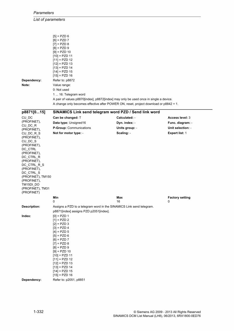
Parameters
List of parameters
1-332 © Siemens AG 2009 - 2013 All Rights ReservedSINAMICS DCM List Manual (LH8), 06/2013, 6RX1800-0ED76
[5] = PZD 6[6] = PZD 7[7] = PZD 8[8] = PZD 9[9] = PZD 10[10] = PZD 11[11] = PZD 12[12] = PZD 13[13] = PZD 14[14] = PZD 15[15] = PZD 16
Dependency: Refer to: p8872
Note: Value range:
0: Not used
1 ... 16: Telegram word
A pair of values p8870[index], p8872[index] may only be used once in single a device.
A change only becomes effective after POWER ON, reset, project download or p8842 = 1.
Description: Assigns a PZD to a telegram word in the SINAMICS Link send telegram.
p8871[index] assigns PZD p2051[index].
Index: [0] = PZD 1[1] = PZD 2[2] = PZD 3[3] = PZD 4[4] = PZD 5[5] = PZD 6[6] = PZD 7[7] = PZD 8[8] = PZD 9[9] = PZD 10[10] = PZD 11[11] = PZD 12[12] = PZD 13[13] = PZD 14[14] = PZD 15[15] = PZD 16
Dependency: Refer to: p2051, p8851
p8871[0...15] SINAMICS Link send telegram word PZD / Send link wordCU_DC (PROFINET), CU_DC_R (PROFINET), CU_DC_R_S (PROFINET), CU_DC_S (PROFINET), DC_CTRL (PROFINET), DC_CTRL_R (PROFINET), DC_CTRL_R_S (PROFINET), DC_CTRL_S (PROFINET), TM150 (PROFINET), TM15DI_DO (PROFINET), TM31 (PROFINET)
Can be changed: T Calculated: - Access level: 3
Data type: Unsigned16 Dyn. index: - Func. diagram: -
P-Group: Communications Units group: - Unit selection: -
Not for motor type: - Scaling: - Expert list: 1
Min Max Factory setting 0 16 0

List of parameters
Parameters
1-333© Siemens AG 2009 - 2013 All Rights ReservedSINAMICS DCM List Manual (LH8), 06/2013, 6RX1800-0ED76
Note: Value range:
0: Not used
1 ... 16: Send telegram word
A specific telegram word send may only be used once within a single device.
A change only becomes effective after POWER ON, reset, project download or p8842 = 1.
Description: Selects the address of the SINAMICS Link sender from which the process data (PZD) is received.
Index: [0] = PZD 1[1] = PZD 2[2] = PZD 3[3] = PZD 4[4] = PZD 5[5] = PZD 6[6] = PZD 7[7] = PZD 8[8] = PZD 9[9] = PZD 10[10] = PZD 11[11] = PZD 12[12] = PZD 13[13] = PZD 14[14] = PZD 15[15] = PZD 16
Dependency: Refer to: p8870
Note: Value range:
0: Not used
1 ... 64: Address
A change only becomes effective after POWER ON, reset, project download or p8842 = 1.
p8872[0...15] SINAMICS Link address receive PZD / Link addr recvCU_DC (PROFINET), CU_DC_R (PROFINET), CU_DC_R_S (PROFINET), CU_DC_S (PROFINET), DC_CTRL (PROFINET), DC_CTRL_R (PROFINET), DC_CTRL_R_S (PROFINET), DC_CTRL_S (PROFINET), TM150 (PROFINET), TM15DI_DO (PROFINET), TM31 (PROFINET)
Can be changed: T Calculated: - Access level: 3
Data type: Unsigned16 Dyn. index: - Func. diagram: -
P-Group: Communications Units group: - Unit selection: -
Not for motor type: - Scaling: - Expert list: 1
Min Max Factory setting 0 64 0

Parameters
List of parameters
1-334 © Siemens AG 2009 - 2013 All Rights ReservedSINAMICS DCM List Manual (LH8), 06/2013, 6RX1800-0ED76
Description: Displays the bus address of sender from which the PZD is received.
Index: [0] = PZD 1[1] = PZD 2[2] = PZD 3[3] = PZD 4[4] = PZD 5[5] = PZD 6[6] = PZD 7[7] = PZD 8[8] = PZD 9[9] = PZD 10[10] = PZD 11[11] = PZD 12[12] = PZD 13[13] = PZD 14[14] = PZD 15[15] = PZD 16[16] = PZD 17[17] = PZD 18[18] = PZD 19[19] = PZD 20[20] = PZD 21[21] = PZD 22[22] = PZD 23[23] = PZD 24[24] = PZD 25[25] = PZD 26[26] = PZD 27[27] = PZD 28[28] = PZD 29[29] = PZD 30[30] = PZD 31[31] = PZD 32[32] = PZD 33[33] = PZD 34[34] = PZD 35[35] = PZD 36[36] = PZD 37[37] = PZD 38[38] = PZD 39[39] = PZD 40[40] = PZD 41[41] = PZD 42[42] = PZD 43[43] = PZD 44[44] = PZD 45[45] = PZD 46[46] = PZD 47[47] = PZD 48[48] = PZD 49[49] = PZD 50[50] = PZD 51[51] = PZD 52[52] = PZD 53
r8874[0...63] IF2 diagnostics bus address PZD receive / IF2 diag addr recvDC_CTRL, DC_CTRL_R, DC_CTRL_R_S, DC_CTRL_S
Can be changed: - Calculated: - Access level: 3
Data type: Unsigned16 Dyn. index: - Func. diagram: -
P-Group: Communications Units group: - Unit selection: -
Not for motor type: - Scaling: - Expert list: 1
Min Max Factory setting - - -

List of parameters
Parameters
1-335© Siemens AG 2009 - 2013 All Rights ReservedSINAMICS DCM List Manual (LH8), 06/2013, 6RX1800-0ED76
[53] = PZD 54[54] = PZD 55[55] = PZD 56[56] = PZD 57[57] = PZD 58[58] = PZD 59[59] = PZD 60[60] = PZD 61[61] = PZD 62[62] = PZD 63[63] = PZD 64
Note: IF2: Interface 2
Value range:
0 - 125: Bus address of the sender
255: Not assigned
Description: Displays the bus address of sender from which the PZD is received.
Index: [0] = PZD 1[1] = PZD 2[2] = PZD 3[3] = PZD 4[4] = PZD 5
Description: Displays the byte offset of the PZD in the receive telegram.
Index: [0] = PZD 1[1] = PZD 2[2] = PZD 3[3] = PZD 4[4] = PZD 5[5] = PZD 6[6] = PZD 7[7] = PZD 8[8] = PZD 9[9] = PZD 10[10] = PZD 11[11] = PZD 12[12] = PZD 13[13] = PZD 14[14] = PZD 15[15] = PZD 16[16] = PZD 17[17] = PZD 18[18] = PZD 19[19] = PZD 20[20] = PZD 21
r8874[0...4] IF2 diagnostics bus address PZD receive / IF2 diag addr recvTM150, TM15DI_DO, TM31
Can be changed: - Calculated: - Access level: 3
Data type: Unsigned16 Dyn. index: - Func. diagram: -
P-Group: Communications Units group: - Unit selection: -
Not for motor type: - Scaling: - Expert list: 1
Min Max Factory setting - - -
r8875[0...63] IF2 diagnostics telegram offset PZD receive / IF diag offs recvDC_CTRL, DC_CTRL_R, DC_CTRL_R_S, DC_CTRL_S
Can be changed: - Calculated: - Access level: 3
Data type: Unsigned16 Dyn. index: - Func. diagram: -
P-Group: Communications Units group: - Unit selection: -
Not for motor type: - Scaling: - Expert list: 1
Min Max Factory setting - - -

Parameters
List of parameters
1-336 © Siemens AG 2009 - 2013 All Rights ReservedSINAMICS DCM List Manual (LH8), 06/2013, 6RX1800-0ED76
[21] = PZD 22[22] = PZD 23[23] = PZD 24[24] = PZD 25[25] = PZD 26[26] = PZD 27[27] = PZD 28[28] = PZD 29[29] = PZD 30[30] = PZD 31[31] = PZD 32[32] = PZD 33[33] = PZD 34[34] = PZD 35[35] = PZD 36[36] = PZD 37[37] = PZD 38[38] = PZD 39[39] = PZD 40[40] = PZD 41[41] = PZD 42[42] = PZD 43[43] = PZD 44[44] = PZD 45[45] = PZD 46[46] = PZD 47[47] = PZD 48[48] = PZD 49[49] = PZD 50[50] = PZD 51[51] = PZD 52[52] = PZD 53[53] = PZD 54[54] = PZD 55[55] = PZD 56[56] = PZD 57[57] = PZD 58[58] = PZD 59[59] = PZD 60[60] = PZD 61[61] = PZD 62[62] = PZD 63[63] = PZD 64
Note: IF2: Interface 2
Value range:
0 - 242: Byte offset
255: Not assigned
Description: Displays the byte offset of the PZD in the receive telegram.
Index: [0] = PZD 1[1] = PZD 2[2] = PZD 3[3] = PZD 4[4] = PZD 5
r8875[0...4] IF2 diagnostics telegram offset PZD receive / IF diag offs recvTM150, TM15DI_DO, TM31
Can be changed: - Calculated: - Access level: 3
Data type: Unsigned16 Dyn. index: - Func. diagram: -
P-Group: Communications Units group: - Unit selection: -
Not for motor type: - Scaling: - Expert list: 1
Min Max Factory setting - - -

List of parameters
Parameters
1-337© Siemens AG 2009 - 2013 All Rights ReservedSINAMICS DCM List Manual (LH8), 06/2013, 6RX1800-0ED76
Description: Displays the byte offset of the PZD in the send telegram.
Index: [0] = PZD 1[1] = PZD 2[2] = PZD 3[3] = PZD 4[4] = PZD 5[5] = PZD 6[6] = PZD 7[7] = PZD 8[8] = PZD 9[9] = PZD 10[10] = PZD 11[11] = PZD 12[12] = PZD 13[13] = PZD 14[14] = PZD 15[15] = PZD 16[16] = PZD 17[17] = PZD 18[18] = PZD 19[19] = PZD 20[20] = PZD 21[21] = PZD 22[22] = PZD 23[23] = PZD 24[24] = PZD 25[25] = PZD 26[26] = PZD 27[27] = PZD 28[28] = PZD 29[29] = PZD 30[30] = PZD 31[31] = PZD 32[32] = PZD 33[33] = PZD 34[34] = PZD 35[35] = PZD 36[36] = PZD 37[37] = PZD 38[38] = PZD 39[39] = PZD 40[40] = PZD 41[41] = PZD 42[42] = PZD 43[43] = PZD 44[44] = PZD 45[45] = PZD 46[46] = PZD 47[47] = PZD 48[48] = PZD 49[49] = PZD 50[50] = PZD 51[51] = PZD 52[52] = PZD 53
r8876[0...63] IF2 diagnostics telegram offset PZD send / IF2 diag offs sendDC_CTRL, DC_CTRL_R, DC_CTRL_R_S, DC_CTRL_S
Can be changed: - Calculated: - Access level: 3
Data type: Unsigned16 Dyn. index: - Func. diagram: -
P-Group: Communications Units group: - Unit selection: -
Not for motor type: - Scaling: - Expert list: 1
Min Max Factory setting - - -

Parameters
List of parameters
1-338 © Siemens AG 2009 - 2013 All Rights ReservedSINAMICS DCM List Manual (LH8), 06/2013, 6RX1800-0ED76
[53] = PZD 54[54] = PZD 55[55] = PZD 56[56] = PZD 57[57] = PZD 58[58] = PZD 59[59] = PZD 60[60] = PZD 61[61] = PZD 62[62] = PZD 63[63] = PZD 64
Note: IF2: Interface 2
Value range:
0 - 242: Byte offset
255: Not assigned
Description: Displays the byte offset of the PZD in the send telegram.
Index: [0] = PZD 1[1] = PZD 2[2] = PZD 3[3] = PZD 4[4] = PZD 5
Description: Selects bits to be sent via interface 2.
The individual bits are combined to form status word 1.
Index: [0] = Bit 0[1] = Bit 1[2] = Bit 2[3] = Bit 3[4] = Bit 4[5] = Bit 5[6] = Bit 6[7] = Bit 7[8] = Bit 8[9] = Bit 9[10] = Bit 10[11] = Bit 11[12] = Bit 12[13] = Bit 13[14] = Bit 14[15] = Bit 15
Dependency: Refer to: p8888, r8889
r8876[0...4] IF2 diagnostics telegram offset PZD send / IF2 diag offs sendTM150, TM15DI_DO, TM31
Can be changed: - Calculated: - Access level: 3
Data type: Unsigned16 Dyn. index: - Func. diagram: -
P-Group: Communications Units group: - Unit selection: -
Not for motor type: - Scaling: - Expert list: 1
Min Max Factory setting - - -
p8880[0...15] BI: IF2 binector-connector converter status word 1 / Bin/con ZSW1DC_CTRL, DC_CTRL_R, DC_CTRL_R_S, DC_CTRL_S
Can be changed: U, T Calculated: - Access level: 3
Data type: Unsigned32 / Binary Dyn. index: - Func. diagram: 2489
P-Group: Communications Units group: - Unit selection: -
Not for motor type: - Scaling: - Expert list: 1
Min Max Factory setting - - 0

List of parameters
Parameters
1-339© Siemens AG 2009 - 2013 All Rights ReservedSINAMICS DCM List Manual (LH8), 06/2013, 6RX1800-0ED76
Description: Selects bits to be sent via interface 2.
The individual bits are combined to form status word 2.
Index: [0] = Bit 0[1] = Bit 1[2] = Bit 2[3] = Bit 3[4] = Bit 4[5] = Bit 5[6] = Bit 6[7] = Bit 7[8] = Bit 8[9] = Bit 9[10] = Bit 10[11] = Bit 11[12] = Bit 12[13] = Bit 13[14] = Bit 14[15] = Bit 15
Dependency: Refer to: p8888, r8889
Description: Selects bits to be sent via interface 2.
The individual bits are combined to form free status word 3.
Index: [0] = Bit 0[1] = Bit 1[2] = Bit 2[3] = Bit 3[4] = Bit 4[5] = Bit 5[6] = Bit 6[7] = Bit 7[8] = Bit 8[9] = Bit 9[10] = Bit 10[11] = Bit 11[12] = Bit 12[13] = Bit 13[14] = Bit 14[15] = Bit 15
Dependency: Refer to: p8888, r8889
p8881[0...15] BI: IF2 binector-connector converter status word 2 / Bin/con ZSW2DC_CTRL, DC_CTRL_R, DC_CTRL_R_S, DC_CTRL_S
Can be changed: U, T Calculated: - Access level: 3
Data type: Unsigned32 / Binary Dyn. index: - Func. diagram: 2489
P-Group: Communications Units group: - Unit selection: -
Not for motor type: - Scaling: - Expert list: 1
Min Max Factory setting - - 0
p8882[0...15] BI: IF2 binector-connector converter status word 3 / Bin/con ZSW3DC_CTRL, DC_CTRL_R, DC_CTRL_R_S, DC_CTRL_S
Can be changed: U, T Calculated: - Access level: 3
Data type: Unsigned32 / Binary Dyn. index: - Func. diagram: 2489
P-Group: Communications Units group: - Unit selection: -
Not for motor type: - Scaling: - Expert list: 1
Min Max Factory setting - - 0

Parameters
List of parameters
1-340 © Siemens AG 2009 - 2013 All Rights ReservedSINAMICS DCM List Manual (LH8), 06/2013, 6RX1800-0ED76
Description: Selects bits to be sent via interface 2.
The individual bits are combined to form free status word 4.
Index: [0] = Bit 0[1] = Bit 1[2] = Bit 2[3] = Bit 3[4] = Bit 4[5] = Bit 5[6] = Bit 6[7] = Bit 7[8] = Bit 8[9] = Bit 9[10] = Bit 10[11] = Bit 11[12] = Bit 12[13] = Bit 13[14] = Bit 14[15] = Bit 15
Dependency: Refer to: p8888, r8889
Description: Selects bits to be sent via interface 2.
The individual bits are combined to form free status word 5.
Index: [0] = Bit 0[1] = Bit 1[2] = Bit 2[3] = Bit 3[4] = Bit 4[5] = Bit 5[6] = Bit 6[7] = Bit 7[8] = Bit 8[9] = Bit 9[10] = Bit 10[11] = Bit 11[12] = Bit 12[13] = Bit 13[14] = Bit 14[15] = Bit 15
Dependency: Refer to: p8888, r8889
p8883[0...15] BI: IF2 binector-connector converter status word 4 / Bin/con ZSW4DC_CTRL, DC_CTRL_R, DC_CTRL_R_S, DC_CTRL_S
Can be changed: U, T Calculated: - Access level: 3
Data type: Unsigned32 / Binary Dyn. index: - Func. diagram: 2489
P-Group: Communications Units group: - Unit selection: -
Not for motor type: - Scaling: - Expert list: 1
Min Max Factory setting - - 0
p8884[0...15] BI: IF2 binector-connector converter status word 5 / Bin/con ZSW5DC_CTRL, DC_CTRL_R, DC_CTRL_R_S, DC_CTRL_S
Can be changed: U, T Calculated: - Access level: 3
Data type: Unsigned32 / Binary Dyn. index: - Func. diagram: 2489
P-Group: Communications Units group: - Unit selection: -
Not for motor type: - Scaling: - Expert list: 1
Min Max Factory setting - - 0

List of parameters
Parameters
1-341© Siemens AG 2009 - 2013 All Rights ReservedSINAMICS DCM List Manual (LH8), 06/2013, 6RX1800-0ED76
Description: Setting to invert the individual binector inputs of the binector connector converter.
Index: [0] = Status word 1[1] = Status word 2[2] = Free status word 3[3] = Free status word 4[4] = Free status word 5
Dependency: Refer to: p8880, p8881, p8882, p8883, p8884, r8889
Description: Connector output to interconnect the status words to a PZD send word.
Index: [0] = Status word 1[1] = Status word 2[2] = Free status word 3[3] = Free status word 4[4] = Free status word 5
p8888[0...4] IF2 invert binector-connector converter status word / Bin/con ZSW invDC_CTRL, DC_CTRL_R, DC_CTRL_R_S, DC_CTRL_S
Can be changed: U, T Calculated: - Access level: 3
Data type: Unsigned16 Dyn. index: - Func. diagram: 2489
P-Group: Communications Units group: - Unit selection: -
Not for motor type: - Scaling: - Expert list: 1
Min Max Factory setting - - 0000 0000 0000 0000 bin
Bit field: Bit Signal name 1 signal 0 signal FP00 Bit 0 Inverted Not inverted -01 Bit 1 Inverted Not inverted -02 Bit 2 Inverted Not inverted -03 Bit 3 Inverted Not inverted -04 Bit 4 Inverted Not inverted -05 Bit 5 Inverted Not inverted -06 Bit 6 Inverted Not inverted -07 Bit 7 Inverted Not inverted -08 Bit 8 Inverted Not inverted -09 Bit 9 Inverted Not inverted -10 Bit 10 Inverted Not inverted -11 Bit 11 Inverted Not inverted -12 Bit 12 Inverted Not inverted -13 Bit 13 Inverted Not inverted -14 Bit 14 Inverted Not inverted -15 Bit 15 Inverted Not inverted -
r8889[0...4] CO: IF2 send binector-connector converter status word / Bin/con ZSW sendDC_CTRL, DC_CTRL_R, DC_CTRL_R_S, DC_CTRL_S
Can be changed: - Calculated: - Access level: 3
Data type: Unsigned16 Dyn. index: - Func. diagram: -
P-Group: Communications Units group: - Unit selection: -
Not for motor type: - Scaling: - Expert list: 1
Min Max Factory setting - - -
Bit field: Bit Signal name 1 signal 0 signal FP00 Bit 0 ON OFF -01 Bit 1 ON OFF -02 Bit 2 ON OFF -03 Bit 3 ON OFF -04 Bit 4 ON OFF -05 Bit 5 ON OFF -06 Bit 6 ON OFF -07 Bit 7 ON OFF -08 Bit 8 ON OFF -09 Bit 9 ON OFF -10 Bit 10 ON OFF -

Parameters
List of parameters
1-342 © Siemens AG 2009 - 2013 All Rights ReservedSINAMICS DCM List Manual (LH8), 06/2013, 6RX1800-0ED76
Dependency: Refer to: p8851, p8880, p8881, p8882, p8883, p8884, p8888
Note: r8889 together with p8880 to p8884 forms five binector-connector converters.
Description: Binector output for bit-serial interconnection of PZD1 (normally control word 1) received via interface 2.
Dependency: Refer to: r8850
Note: IF2: Interface 2
Description: Binector output for bit-serial interconnection of PZD2 received via interface 2.
11 Bit 11 ON OFF -12 Bit 12 ON OFF -13 Bit 13 ON OFF -14 Bit 14 ON OFF -15 Bit 15 ON OFF -
r8890.0...15 BO: IF2 PZD1 receive bit-serial / IF2 PZD1 recv bitwDC_CTRL, DC_CTRL_R, DC_CTRL_R_S, DC_CTRL_S, TM150, TM15DI_DO, TM31
Can be changed: - Calculated: - Access level: 3
Data type: Unsigned16 Dyn. index: - Func. diagram: 2485, 2491, 9204, 9206
P-Group: Communications Units group: - Unit selection: -
Not for motor type: - Scaling: - Expert list: 1
Min Max Factory setting - - -
Bit field: Bit Signal name 1 signal 0 signal FP00 Bit 0 ON OFF -01 Bit 1 ON OFF -02 Bit 2 ON OFF -03 Bit 3 ON OFF -04 Bit 4 ON OFF -05 Bit 5 ON OFF -06 Bit 6 ON OFF -07 Bit 7 ON OFF -08 Bit 8 ON OFF -09 Bit 9 ON OFF -10 Bit 10 ON OFF -11 Bit 11 ON OFF -12 Bit 12 ON OFF -13 Bit 13 ON OFF -14 Bit 14 ON OFF -15 Bit 15 ON OFF -
r8891.0...15 BO: IF2 PZD2 receive bit-serial / IF2 PZD2 recv bitwDC_CTRL, DC_CTRL_R, DC_CTRL_R_S, DC_CTRL_S, TM150, TM15DI_DO, TM31
Can be changed: - Calculated: - Access level: 3
Data type: Unsigned16 Dyn. index: - Func. diagram: 2485, 2491, 9204, 9206
P-Group: Communications Units group: - Unit selection: -
Not for motor type: - Scaling: - Expert list: 1
Min Max Factory setting - - -
Bit field: Bit Signal name 1 signal 0 signal FP00 Bit 0 ON OFF -01 Bit 1 ON OFF -02 Bit 2 ON OFF -03 Bit 3 ON OFF -04 Bit 4 ON OFF -05 Bit 5 ON OFF -06 Bit 6 ON OFF -07 Bit 7 ON OFF -08 Bit 8 ON OFF -09 Bit 9 ON OFF -

List of parameters
Parameters
1-343© Siemens AG 2009 - 2013 All Rights ReservedSINAMICS DCM List Manual (LH8), 06/2013, 6RX1800-0ED76
Dependency: Refer to: r8850
Note: IF2: Interface 2
Description: Binector output for bit-serial interconnection of PZD3 received via interface 2.
Dependency: Refer to: r8850
Note: IF2: Interface 2
Description: Binector output for bit-serial interconnection of PZD4 (normally control word 2) received via interface 2.
10 Bit 10 ON OFF -11 Bit 11 ON OFF -12 Bit 12 ON OFF -13 Bit 13 ON OFF -14 Bit 14 ON OFF -15 Bit 15 ON OFF -
r8892.0...15 BO: IF2 PZD3 receive bit-serial / IF2 PZD3 recv bitwDC_CTRL, DC_CTRL_R, DC_CTRL_R_S, DC_CTRL_S
Can be changed: - Calculated: - Access level: 3
Data type: Unsigned16 Dyn. index: - Func. diagram: 2485, 9204, 9206
P-Group: Communications Units group: - Unit selection: -
Not for motor type: - Scaling: - Expert list: 1
Min Max Factory setting - - -
Bit field: Bit Signal name 1 signal 0 signal FP00 Bit 0 ON OFF -01 Bit 1 ON OFF -02 Bit 2 ON OFF -03 Bit 3 ON OFF -04 Bit 4 ON OFF -05 Bit 5 ON OFF -06 Bit 6 ON OFF -07 Bit 7 ON OFF -08 Bit 8 ON OFF -09 Bit 9 ON OFF -10 Bit 10 ON OFF -11 Bit 11 ON OFF -12 Bit 12 ON OFF -13 Bit 13 ON OFF -14 Bit 14 ON OFF -15 Bit 15 ON OFF -
r8893.0...15 BO: IF2 PZD4 receive bit-serial / IF2 PZD4 recv bitwDC_CTRL, DC_CTRL_R, DC_CTRL_R_S, DC_CTRL_S
Can be changed: - Calculated: - Access level: 3
Data type: Unsigned16 Dyn. index: - Func. diagram: 2485, 9204, 9206
P-Group: Communications Units group: - Unit selection: -
Not for motor type: - Scaling: - Expert list: 1
Min Max Factory setting - - -
Bit field: Bit Signal name 1 signal 0 signal FP00 Bit 0 ON OFF -01 Bit 1 ON OFF -02 Bit 2 ON OFF -03 Bit 3 ON OFF -04 Bit 4 ON OFF -05 Bit 5 ON OFF -06 Bit 6 ON OFF -07 Bit 7 ON OFF -08 Bit 8 ON OFF -09 Bit 9 ON OFF -

Parameters
List of parameters
1-344 © Siemens AG 2009 - 2013 All Rights ReservedSINAMICS DCM List Manual (LH8), 06/2013, 6RX1800-0ED76
Dependency: Refer to: r8850
Note: IF2: Interface 2
Description: Binector output for bit-serial interconnection of a PZD word received via interface 2.
The PZD is selected via p8899[0].
Dependency: Refer to: p8899
Description: Binector output for bit-serial interconnection of a PZD word received via interface 2.
The PZD is selected via p8899[1].
10 Bit 10 ON OFF -11 Bit 11 ON OFF -12 Bit 12 ON OFF -13 Bit 13 ON OFF -14 Bit 14 ON OFF -15 Bit 15 ON OFF -
r8894.0...15 BO: IF2 connector-binector converter binector output / Con/bin outpDC_CTRL, DC_CTRL_R, DC_CTRL_R_S, DC_CTRL_S
Can be changed: - Calculated: - Access level: 3
Data type: Unsigned16 Dyn. index: - Func. diagram: 2485, 2491
P-Group: Communications Units group: - Unit selection: -
Not for motor type: - Scaling: - Expert list: 1
Min Max Factory setting - - -
Bit field: Bit Signal name 1 signal 0 signal FP00 Bit 0 ON OFF -01 Bit 1 ON OFF -02 Bit 2 ON OFF -03 Bit 3 ON OFF -04 Bit 4 ON OFF -05 Bit 5 ON OFF -06 Bit 6 ON OFF -07 Bit 7 ON OFF -08 Bit 8 ON OFF -09 Bit 9 ON OFF -10 Bit 10 ON OFF -11 Bit 11 ON OFF -12 Bit 12 ON OFF -13 Bit 13 ON OFF -14 Bit 14 ON OFF -15 Bit 15 ON OFF -
r8895.0...15 BO: IF2 connector-binector converter binector output / Con/bin outpDC_CTRL, DC_CTRL_R, DC_CTRL_R_S, DC_CTRL_S
Can be changed: - Calculated: - Access level: 3
Data type: Unsigned16 Dyn. index: - Func. diagram: 2485, 2491
P-Group: Communications Units group: - Unit selection: -
Not for motor type: - Scaling: - Expert list: 1
Min Max Factory setting - - -
Bit field: Bit Signal name 1 signal 0 signal FP00 Bit 0 ON OFF -01 Bit 1 ON OFF -02 Bit 2 ON OFF -03 Bit 3 ON OFF -04 Bit 4 ON OFF -05 Bit 5 ON OFF -06 Bit 6 ON OFF -07 Bit 7 ON OFF -08 Bit 8 ON OFF -09 Bit 9 ON OFF -

List of parameters
Parameters
1-345© Siemens AG 2009 - 2013 All Rights ReservedSINAMICS DCM List Manual (LH8), 06/2013, 6RX1800-0ED76
Dependency: Refer to: p8898, p8899
Description: Setting to invert the individual binector outputs of the connector-binector converter.
Using p8898[0], the signals of CI: p8899[0] are influenced.
Using p8898[1], the signals of CI: p8899[1] are influenced.
Dependency: Refer to: r8894, r8895, p8899
Description: Sets the signal source for the connector-binector converter.
A PZD receive word can be selected as signal source. The signals are available to be serially passed-on (intercon-nection).
Dependency: Refer to: r8850, r8894, r8895, p8898
Note: From the signal source set via the connector input, the corresponding lower 16 bits are converted.
p8899[0...1] together with r8894.0...15 and r8895.0...15 forms two connector-binector converters:
Connector input p8899[0] to binector output in r8894.0...15
Connector input p8899[1] to binector output in r8895.0...15
10 Bit 10 ON OFF -11 Bit 11 ON OFF -12 Bit 12 ON OFF -13 Bit 13 ON OFF -14 Bit 14 ON OFF -15 Bit 15 ON OFF -
p8898[0...1] IF2 invert connector-binector converter binector output / Con/bin outp invDC_CTRL, DC_CTRL_R, DC_CTRL_R_S, DC_CTRL_S
Can be changed: U, T Calculated: - Access level: 3
Data type: Unsigned16 Dyn. index: - Func. diagram: 2485, 2491
P-Group: Communications Units group: - Unit selection: -
Not for motor type: - Scaling: - Expert list: 1
Min Max Factory setting - - 0000 0000 0000 0000 bin
Bit field: Bit Signal name 1 signal 0 signal FP00 Bit 0 Inverted Not inverted -01 Bit 1 Inverted Not inverted -02 Bit 2 Inverted Not inverted -03 Bit 3 Inverted Not inverted -04 Bit 4 Inverted Not inverted -05 Bit 5 Inverted Not inverted -06 Bit 6 Inverted Not inverted -07 Bit 7 Inverted Not inverted -08 Bit 8 Inverted Not inverted -09 Bit 9 Inverted Not inverted -10 Bit 10 Inverted Not inverted -11 Bit 11 Inverted Not inverted -12 Bit 12 Inverted Not inverted -13 Bit 13 Inverted Not inverted -14 Bit 14 Inverted Not inverted -15 Bit 15 Inverted Not inverted -
p8899[0...1] CI: IF2 connector-binector converter signal source / Con/bin S_srcDC_CTRL, DC_CTRL_R, DC_CTRL_R_S, DC_CTRL_S
Can be changed: U, T Calculated: - Access level: 3
Data type: Unsigned32 / Integer16 Dyn. index: - Func. diagram: 2485, 2491
P-Group: Communications Units group: - Unit selection: -
Not for motor type: - Scaling: - Expert list: 1
Min Max Factory setting - - 0

Parameters
List of parameters
1-346 © Siemens AG 2009 - 2013 All Rights ReservedSINAMICS DCM List Manual (LH8), 06/2013, 6RX1800-0ED76
Description: Displays the PROFINET Device ID.
Every SINAMICS device type has its own PROFINET Device ID and its own PROFINET GSD.
Note: List of the SINAMICS Device IDs:
0501 hex: S120/S150
0504 hex: G130/G150
050A hex: DC MASTER
050C hex: MV
050F hex: G120P
0510 hex: G120C
0511 hex: G120 CU240E-2
0512 hex: G120D
0513 hex: G120 CU250S-2 Vector
0514 hex: G110M
0515 hex: G120 CU250S-2 Servo
Description: Sets the station name for the Communication Board Ethernet 20 (CBE20).
Note: An ASCII table (excerpt) can be found, for example, in the appendix to the List Manual.
The parameter is only valid for firmware version "PROFINET Device" (p8835 = 1) or "Ethernet/IP" (p8835 = 4).
The interface configuration (p8940 and following) is activated with p8945 = 2 (becomes effective after the next POWER ON).
The parameter is not influenced by setting the factory setting.
Description: Sets the IP address for the Communication Board Ethernet 20 (CBE20).
r8909 PN device ID / PN device IDCU_DC, CU_DC_R, CU_DC_R_S, CU_DC_S
Can be changed: - Calculated: - Access level: 3
Data type: Unsigned16 Dyn. index: - Func. diagram: -
P-Group: - Units group: - Unit selection: -
Not for motor type: - Scaling: - Expert list: 1
Min Max Factory setting - - -
p8940[0...239] CBE20 Name of Station / CBE20 Name StatCU_DC (PROFINET), CU_DC_R (PROFINET), CU_DC_R_S (PROFINET), CU_DC_S (PROFINET)
Can be changed: U, T Calculated: - Access level: 3
Data type: Unsigned8 Dyn. index: - Func. diagram: -
P-Group: - Units group: - Unit selection: -
Not for motor type: - Scaling: - Expert list: 1
Min Max Factory setting - - -
p8941[0...3] CBE20 IP Address of Station / CBE20 IP of StatCU_DC (PROFINET), CU_DC_R (PROFINET), CU_DC_R_S (PROFINET), CU_DC_S (PROFINET)
Can be changed: U, T Calculated: - Access level: 3
Data type: Unsigned8 Dyn. index: - Func. diagram: -
P-Group: - Units group: - Unit selection: -
Not for motor type: - Scaling: - Expert list: 1
Min Max Factory setting 0 255 0

List of parameters
Parameters
1-347© Siemens AG 2009 - 2013 All Rights ReservedSINAMICS DCM List Manual (LH8), 06/2013, 6RX1800-0ED76
Note: The parameter is only valid for firmware version "PROFINET Device" (p8835 = 1) or "Ethernet/IP" (p8835 = 4).
The interface configuration (p8940 and following) is activated with p8945 = 2 (becomes effective after the next POWER ON).
The parameter is not influenced by setting the factory setting.
Description: Sets the default gateway for the Communication Board Ethernet 20 (CBE20).
Note: The parameter is only valid for firmware version "PROFINET Device" (p8835 = 1) or "Ethernet/IP" (p8835 = 4).
The interface configuration (p8940 and following) is activated with p8945 = 2 (becomes effective after the next POWER ON).
The parameter is not influenced by setting the factory setting.
Description: Sets the subnet mask for the Communication Board Ethernet 20 (CBE20).
Note: The parameter is only valid for firmware version "PROFINET Device" (p8835 = 1) or "Ethernet/IP" (p8835 = 4).
The interface configuration (p8940 and following) is activated with p8945 = 2 (becomes effective after the next POWER ON).
The parameter is not influenced by setting the factory setting.
Description: Sets the DHCP mode for the Communication Board Ethernet 20 (CBE20).
Note: The parameter is only valid for firmware version "PROFINET Device" (p8835 = 1) or "Ethernet/IP" (p8835 = 4).
The interface configuration (p8940 and following) is activated with p8945 = 2 (becomes effective after the next POWER ON).
The parameter is not influenced by setting the factory setting.
p8942[0...3] CBE20 Default Gateway of Station / CBE20 Def GatewayCU_DC (PROFINET), CU_DC_R (PROFINET), CU_DC_R_S (PROFINET), CU_DC_S (PROFINET)
Can be changed: U, T Calculated: - Access level: 3
Data type: Unsigned8 Dyn. index: - Func. diagram: -
P-Group: - Units group: - Unit selection: -
Not for motor type: - Scaling: - Expert list: 1
Min Max Factory setting 0 255 0
p8943[0...3] CBE20 Subnet Mask of Station / CBE20 Subnet MaskCU_DC (PROFINET), CU_DC_R (PROFINET), CU_DC_R_S (PROFINET), CU_DC_S (PROFINET)
Can be changed: U, T Calculated: - Access level: 3
Data type: Unsigned8 Dyn. index: - Func. diagram: -
P-Group: - Units group: - Unit selection: -
Not for motor type: - Scaling: - Expert list: 1
Min Max Factory setting 0 255 0
p8944 CBE20 DHCP Mode / CBE20 DHCP ModeCU_DC (PROFINET), CU_DC_R (PROFINET), CU_DC_R_S (PROFINET), CU_DC_S (PROFINET)
Can be changed: U, T Calculated: - Access level: 3
Data type: Unsigned8 Dyn. index: - Func. diagram: -
P-Group: - Units group: - Unit selection: -
Not for motor type: - Scaling: - Expert list: 1
Min Max Factory setting 0 255 0

Parameters
List of parameters
1-348 © Siemens AG 2009 - 2013 All Rights ReservedSINAMICS DCM List Manual (LH8), 06/2013, 6RX1800-0ED76
Description: Sets the activation of the interface configuration for the Communication Board Ethernet 20 (CBE20).
p8945 is automatically set to 0 at the end of an operation.
Value: 0: No function2: Save and activate configuration3: Delete configuration
Note: The parameter is only valid for firmware version "PROFINET Device" (p8835 = 1) or "Ethernet/IP" (p8835 = 4). Oth-erwise, it is locked.
Re p8945 = 2:
The interface configuration (p8940 and following) is saved and activated after the next POWER ON.
Re p8945 = 3:
The factory setting of the interface configuration is loaded after the next POWER ON.
Description: Displays the active station name for the Communication Board Ethernet 20 (CBE20).
Description: Displays the active IP address for the Communication Board Ethernet 20 (CBE20).
p8945 CBE20 interface configuration / CBE20 IF configCU_DC (PROFINET), CU_DC_R (PROFINET), CU_DC_R_S (PROFINET), CU_DC_S (PROFINET)
Can be changed: U, T Calculated: - Access level: 3
Data type: Integer16 Dyn. index: - Func. diagram: -
P-Group: - Units group: - Unit selection: -
Not for motor type: - Scaling: - Expert list: 1
Min Max Factory setting 0 3 0
r8950[0...239] CBE20 Name of Station active / CBE20 name actCU_DC (PROFINET), CU_DC_R (PROFINET), CU_DC_R_S (PROFINET), CU_DC_S (PROFINET)
Can be changed: - Calculated: - Access level: 3
Data type: Unsigned8 Dyn. index: - Func. diagram: -
P-Group: - Units group: - Unit selection: -
Not for motor type: - Scaling: - Expert list: 1
Min Max Factory setting - - -
r8951[0...3] CBE20 IP Address of Station active / CBE20 IP actCU_DC (PROFINET), CU_DC_R (PROFINET), CU_DC_R_S (PROFINET), CU_DC_S (PROFINET)
Can be changed: - Calculated: - Access level: 3
Data type: Unsigned8 Dyn. index: - Func. diagram: -
P-Group: - Units group: - Unit selection: -
Not for motor type: - Scaling: - Expert list: 1
Min Max Factory setting 0 255 -

List of parameters
Parameters
1-349© Siemens AG 2009 - 2013 All Rights ReservedSINAMICS DCM List Manual (LH8), 06/2013, 6RX1800-0ED76
Description: Displays the active standard gateway for the Communication Board Ethernet 20 (CBE20).
Description: Displays the active subnet mask for the Communication Board Ethernet 20 (CBE20).
Description: Displays the active DHCP mode for the Communication Board Ethernet 20 (CBE20).
Description: Displays the MAC address for the Communication Board Ethernet 20 (CBE20).
r8952[0...3] CBE20 Default Gateway of Station active / CBE20 def GW actCU_DC (PROFINET), CU_DC_R (PROFINET), CU_DC_R_S (PROFINET), CU_DC_S (PROFINET)
Can be changed: - Calculated: - Access level: 3
Data type: Unsigned8 Dyn. index: - Func. diagram: -
P-Group: - Units group: - Unit selection: -
Not for motor type: - Scaling: - Expert list: 1
Min Max Factory setting 0 255 -
r8953[0...3] CBE20 Subnet Mask of Station active / CBE20 sub mask actCU_DC (PROFINET), CU_DC_R (PROFINET), CU_DC_R_S (PROFINET), CU_DC_S (PROFINET)
Can be changed: - Calculated: - Access level: 3
Data type: Unsigned8 Dyn. index: - Func. diagram: -
P-Group: - Units group: - Unit selection: -
Not for motor type: - Scaling: - Expert list: 1
Min Max Factory setting 0 255 -
r8954 CBE20 DHCP Mode active / CBE20 DHCP actCU_DC (PROFINET), CU_DC_R (PROFINET), CU_DC_R_S (PROFINET), CU_DC_S (PROFINET)
Can be changed: - Calculated: - Access level: 3
Data type: Unsigned8 Dyn. index: - Func. diagram: -
P-Group: - Units group: - Unit selection: -
Not for motor type: - Scaling: - Expert list: 1
Min Max Factory setting 0 255 -
r8955[0...5] CBE20 MAC Address of Station / CBE20 MAC addrCU_DC (PROFINET), CU_DC_R (PROFINET), CU_DC_R_S (PROFINET), CU_DC_S (PROFINET)
Can be changed: - Calculated: - Access level: 3
Data type: Unsigned8 Dyn. index: - Func. diagram: -
P-Group: - Units group: - Unit selection: -
Not for motor type: - Scaling: - Expert list: 1
Min Max Factory setting 0000 hex 00FF hex -

Parameters
List of parameters
1-350 © Siemens AG 2009 - 2013 All Rights ReservedSINAMICS DCM List Manual (LH8), 06/2013, 6RX1800-0ED76
Description: Displays the PROFINET Device Access Point ID (DAP ID) for PROFINET CBE20.
The combination of device ID (r8909) and DAP ID uniquely identifies a PROFINET access point.
Note: List of the SINAMICS CBE20 DAP IDs:
20007 hex: CBE20 V4.5
20008 hex: CBE20 V4.6
Description: Displays the controller assignment of a PROFINET subslot on the actual drive object.
Index: [0] = Subslot 2 PROFIsafe[1] = Subslot 3 PZD telegram[2] = Subslot 4 PZD supplementary data
Note: Example:
If the parameter contains the value 2 in index [1], then this means that subslot 3 is assigned to controller 2.
Description: Displays the controller assignment of a PROFINET subslot on the actual drive object.
r8959 CBE20 DAP ID / CBE20 DAP IDCU_DC (PROFINET), CU_DC_R (PROFINET), CU_DC_R_S (PROFINET), CU_DC_S (PROFINET)
Can be changed: - Calculated: - Access level: 3
Data type: Unsigned32 Dyn. index: - Func. diagram: -
P-Group: - Units group: - Unit selection: -
Not for motor type: - Scaling: - Expert list: 1
Min Max Factory setting 0000 hex FFFF FFFF hex -
r8960[0...2] PN subslot controller assignment / PN subslot assignAll objects Can be changed: - Calculated: - Access level: 3
Data type: Unsigned8 Dyn. index: - Func. diagram: -
P-Group: - Units group: - Unit selection: -
Not for motor type: - Scaling: - Expert list: 1
Min Max Factory setting 0 8 -
r8970[0...2] CBE20 subslot controller assignment / CBE20 subslotCU_DC (PROFINET), CU_DC_R (PROFINET), CU_DC_R_S (PROFINET), CU_DC_S (PROFINET), DC_CTRL (PROFINET), DC_CTRL_R (PROFINET), DC_CTRL_R_S (PROFINET), DC_CTRL_S (PROFINET), TM150 (PROFINET), TM15DI_DO (PROFINET), TM31 (PROFINET)
Can be changed: - Calculated: - Access level: 3
Data type: Unsigned8 Dyn. index: - Func. diagram: -
P-Group: - Units group: - Unit selection: -
Not for motor type: - Scaling: - Expert list: 1
Min Max Factory setting 0 8 -
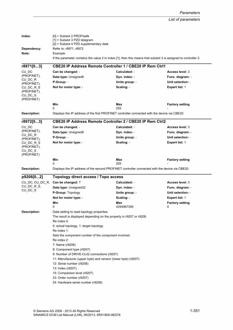
List of parameters
Parameters
1-351© Siemens AG 2009 - 2013 All Rights ReservedSINAMICS DCM List Manual (LH8), 06/2013, 6RX1800-0ED76
Index: [0] = Subslot 2 PROFIsafe[1] = Subslot 3 PZD telegram[2] = Subslot 4 PZD supplementary data
Dependency: Refer to: r8971, r8972
Note: Example:
If the parameter contains the value 2 in index [1], then this means that subslot 3 is assigned to controller 2.
Description: Displays the IP address of the first PROFINET controller connected with the device via CBE20.
Description: Displays the IP address of the second PROFINET controller connected with the device via CBE20.
Description: Data setting to read topology properties.
The result is displayed depending on the property in r9207 or r9208.
Re index 0:
0: actual topology, 1: target topology
Re index 1:
Sets the component number of the component involved.
Re index 2:
7: Name (r9208)
8: Component type (r9207)
9: Number of DRIVE-CLiQ connections (r9207)
11: Manufacturer (upper byte) and version (lower byte) (r9207)
12: Serial number (r9208)
13: Index (r9207)
15: Comparison level (r9207)
23: Order number (r9207)
24: Hardware serial number (r9208)
r8971[0...3] CBE20 IP Address Remote Controller 1 / CBE20 IP Rem Ctrl1CU_DC (PROFINET), CU_DC_R (PROFINET), CU_DC_R_S (PROFINET), CU_DC_S (PROFINET)
Can be changed: - Calculated: - Access level: 3
Data type: Unsigned8 Dyn. index: - Func. diagram: -
P-Group: - Units group: - Unit selection: -
Not for motor type: - Scaling: - Expert list: 1
Min Max Factory setting 0 255 -
r8972[0...3] CBE20 IP Address Remote Controller 2 / CBE20 IP Rem Ctrl2CU_DC (PROFINET), CU_DC_R (PROFINET), CU_DC_R_S (PROFINET), CU_DC_S (PROFINET)
Can be changed: - Calculated: - Access level: 3
Data type: Unsigned8 Dyn. index: - Func. diagram: -
P-Group: - Units group: - Unit selection: -
Not for motor type: - Scaling: - Expert list: 1
Min Max Factory setting 0 255 -
p9206[0...2] Topology direct access / Topo accessCU_DC, CU_DC_R, CU_DC_R_S, CU_DC_S
Can be changed: T Calculated: - Access level: 3
Data type: Unsigned32 Dyn. index: - Func. diagram: -
P-Group: Topology Units group: - Unit selection: -
Not for motor type: - Scaling: - Expert list: 1
Min Max Factory setting 0 4294967295 0

Parameters
List of parameters
1-352 © Siemens AG 2009 - 2013 All Rights ReservedSINAMICS DCM List Manual (LH8), 06/2013, 6RX1800-0ED76
25: Collective order number (r9207)
28: Firmware version (r9207)
29: EPROM version (r9207)
30: Hardware version (r9207)
Index: [0] = Actual topology/target topology[1] = Component number[2] = Identifier/property
Dependency: Refer to: r9207, r9208
Description: Displays the value for the property set in p9206.
A value is only displayed for integer type properties.
Dependency: Refer to: p9206, r9208
Description: Displays the value for the property set in p9206.
A value is only displayed for string type properties.
Dependency: Refer to: p9206, r9207
Note: An ASCII table (excerpt) can be found, for example, in the appendix to the List Manual.
Description: Sets the component number for a component to get its status LED to flash.
Dependency: Refer to: p9211
Description: Sets the function for the component selected in p9210.
After initiating a function, the parameter is automatically reset again.
r9207 Topology direct access integer value / Topo access intCU_DC, CU_DC_R, CU_DC_R_S, CU_DC_S
Can be changed: - Calculated: - Access level: 3
Data type: Unsigned32 Dyn. index: - Func. diagram: -
P-Group: Topology Units group: - Unit selection: -
Not for motor type: - Scaling: - Expert list: 1
Min Max Factory setting - - -
r9208[0...50] Topology direct access string / Topo access stringCU_DC, CU_DC_R, CU_DC_R_S, CU_DC_S
Can be changed: - Calculated: - Access level: 3
Data type: Unsigned8 Dyn. index: - Func. diagram: -
P-Group: Topology Units group: - Unit selection: -
Not for motor type: - Scaling: - Expert list: 1
Min Max Factory setting - - -
p9210 Flashing component number / Flash comp_noCU_DC, CU_DC_R, CU_DC_R_S, CU_DC_S
Can be changed: U, T Calculated: - Access level: 3
Data type: Unsigned16 Dyn. index: - Func. diagram: -
P-Group: Topology Units group: - Unit selection: -
Not for motor type: - Scaling: - Expert list: 1
Min Max Factory setting 0 499 0
p9211 Flash function / Flash fct.CU_DC, CU_DC_R, CU_DC_R_S, CU_DC_S
Can be changed: U, T Calculated: - Access level: 3
Data type: Integer16 Dyn. index: - Func. diagram: -
P-Group: Topology Units group: - Unit selection: -
Not for motor type: - Scaling: - Expert list: 1
Min Max Factory setting -1 1 -1

List of parameters
Parameters
1-353© Siemens AG 2009 - 2013 All Rights ReservedSINAMICS DCM List Manual (LH8), 06/2013, 6RX1800-0ED76
Example:
- Set the component number (p9210).
- Select the "flashing on" function (set p9211 = 1).
Value: -1: Select function0: Flashing off1: Flashing on
Dependency: Refer to: p9210
Notice: If a task cannot be executed (e.g. the component number in p9210 does not exist), the following applies:
- There is no negative feedback signal.
- The value is reset anyway.
Description: Setting and display when memory card is "removed safely".
Procedure:
Setting p9400 = 2 results in a value of 3
--> The memory card can be removed safely. After removal the value sets itself to 0 automatically.
Setting p9400 = 2 results in a value of 100
--> The memory card cannot be removed safely. Removal may destroy the file system on the memory card. It may be necessary to set p9400 = 2 again.
Value: 0: No memory card inserted1: Memory card inserted2: Request "safe removal" of the memory card3: "Safe removal" possible100: "Safe removal" not possible due to access
Dependency: Refer to: r9401
Notice: Removing the memory card without a request (p9400 = 2) and confirmation (p9400 = 3) may destroy the file system on the memory card. The memory card will then no longer work properly and must be replaced.
Note: The status when the memory card is being "removed safely" is shown in r9401.
Re value = 0, 1, 3, 100:
These values can only be displayed, not set.
Description: Displays the status of the memory card.
Dependency: Refer to: p9400
p9400 Safely remove memory card / Mem_card remCU_DC, CU_DC_R, CU_DC_R_S, CU_DC_S
Can be changed: T Calculated: - Access level: 2
Data type: Integer16 Dyn. index: - Func. diagram: -
P-Group: - Units group: - Unit selection: -
Not for motor type: - Scaling: - Expert list: 1
Min Max Factory setting 0 100 0
r9401 Safely remove memory card status / Mem_card rem statCU_DC, CU_DC_R, CU_DC_R_S, CU_DC_S
Can be changed: - Calculated: - Access level: 2
Data type: Unsigned16 Dyn. index: - Func. diagram: -
P-Group: - Units group: - Unit selection: -
Not for motor type: - Scaling: - Expert list: 1
Min Max Factory setting - - -
Bit field: Bit Signal name 1 signal 0 signal FP00 Memory card inserted Yes No -01 Memory card activated Yes No -02 SIEMENS memory card Yes No -03 Memory card as USB data storage medium
from the PC usedYes No -

Parameters
List of parameters
1-354 © Siemens AG 2009 - 2013 All Rights ReservedSINAMICS DCM List Manual (LH8), 06/2013, 6RX1800-0ED76
Note: Re bit 00 and bit 01:
Bit 1/0 = 0/0: No memory card inserted (corresponds to p9400 = 0).
Bit 1/0 = 0/1: "Safe removal" possible (corresponds to p9400 = 3).
Bit 1/0 = 1/0: Status not possible.
Bit 1/0 = 1/1: Memory card inserted (corresponds to p9400 = 1, 2, 100).
Re bit 00 and bit 02:
Bit 2/0 = 0/0: No memory card inserted.
Bit 2/0 = 0/1: Memory card inserted, but not a SIEMENS memory card.
Bit 2/0 = 1/0: Status not possible.
Bit 2/0 = 1/1: SIEMENS memory card inserted.
Description: Displays the parameters that were not able to be transferred when reading the parameter back-up files (PS files) from the non-volatile memory (e.g. memory card).
r9406[0] = 0
--> All of the parameter values were able to be transferred error-free.
r9406[0...x] > 0
--> indicates the parameter number in the following cases:
- parameter, whose value was not able to be completely accepted.
- indexed parameter, where at least 1 index was not able to be accepted. The first index that is not transferred is displayed in r9407.
Dependency: Refer to: r9407, r9408
Note: All indices from r9406 to r9408 designate the same parameter.
r9406[x] parameter number, parameter not accepted
r9407[x] parameter index, parameter not accepted
r9408[x] fault code, parameter not accepted
Description: Displays the first index of the parameters that could not be transferred when the parameter backup files (PS files) were read from the non-volatile memory (e.g. memory card).
If, from an indexed parameter, at least one index was not able to be transferred, then the parameter number is dis-played in r9406[n] and the first index that was not transferred is displayed in r9407[n].
r9406[0] = 0
--> All of the parameter values were able to be transferred error-free.
r9406[n] > 0
--> Displays r9407[n] the first index of the parameter number r9406[n] that was not transferred.
Dependency: Refer to: r9406, r9408
Note: All indices from r9406 to r9408 designate the same parameter.
r9406[x] parameter number, parameter not accepted
r9407[x] parameter index, parameter not accepted
r9408[x] fault code, parameter not accepted
r9406[0...19] PS file parameter number parameter not transferred / PS par_no n transfAll objects Can be changed: - Calculated: - Access level: 4
Data type: Unsigned16 Dyn. index: - Func. diagram: -
P-Group: - Units group: - Unit selection: -
Not for motor type: - Scaling: - Expert list: 1
Min Max Factory setting - - -
r9407[0...19] PS file parameter index parameter not transferred / PS parameter indexAll objects Can be changed: - Calculated: - Access level: 1
Data type: Unsigned16 Dyn. index: - Func. diagram: -
P-Group: - Units group: - Unit selection: -
Not for motor type: - Scaling: - Expert list: 1
Min Max Factory setting - - -

List of parameters
Parameters
1-355© Siemens AG 2009 - 2013 All Rights ReservedSINAMICS DCM List Manual (LH8), 06/2013, 6RX1800-0ED76
Description: Only for internal Siemens service purposes.
Dependency: Refer to: r9406, r9407
Note: All indices from r9406 to r9408 designate the same parameter.
r9406[x] parameter number, parameter not accepted
r9407[x] parameter index, parameter not accepted
r9408[x] fault code, parameter not accepted
Description: Displays the number of modified parameters and those that have still not be saved for this drive object.
Dependency: Refer to: p0971, p0977
Notice: Inherent to the system, the list of the parameters to be backed up is empty after the following actions:
- Download
- Warm restart
- Factory setting
In these cases, a new parameter backup must be initiated, which is then the starting point for the list of modified parameters.
Note: The modified parameters that still need to be saved are internally listed in r9410 ... r9419.
Description: Displays the parameters for which the re-calculation was unsuccessful after an internal system reference value change.
Description: Displays the parameters whose parameter would have to be changed during a units changeover.
r9408[0...19] PS file fault code parameter not transferred / PS fault codeAll objects Can be changed: - Calculated: - Access level: 1
Data type: Unsigned16 Dyn. index: - Func. diagram: -
P-Group: - Units group: - Unit selection: -
Not for motor type: - Scaling: - Expert list: 1
Min Max Factory setting - - -
r9409 Number of parameters to be saved / Qty par to saveAll objects Can be changed: - Calculated: - Access level: 4
Data type: Unsigned16 Dyn. index: - Func. diagram: -
P-Group: - Units group: - Unit selection: -
Not for motor type: - Scaling: - Expert list: 1
Min Max Factory setting - - -
r9450[0...29] Reference value change parameter with unsuccessful calculation / Ref_chg par n poss
DC_CTRL, DC_CTRL_R, DC_CTRL_R_S, DC_CTRL_S
Can be changed: - Calculated: - Access level: 2
Data type: Unsigned32 Dyn. index: - Func. diagram: -
P-Group: - Units group: - Unit selection: -
Not for motor type: - Scaling: - Expert list: 1
Min Max Factory setting - - -
r9451[0...29] Units changeover adapted parameters / Unit_chngov parDC_CTRL, DC_CTRL_R, DC_CTRL_R_S, DC_CTRL_S
Can be changed: - Calculated: - Access level: 1
Data type: Unsigned32 Dyn. index: - Func. diagram: -
P-Group: - Units group: - Unit selection: -
Not for motor type: - Scaling: - Expert list: 1
Min Max Factory setting - - -

Parameters
List of parameters
1-356 © Siemens AG 2009 - 2013 All Rights ReservedSINAMICS DCM List Manual (LH8), 06/2013, 6RX1800-0ED76
Description: Displays the number of BICO interconnections (signal sinks).
Dependency: Refer to: r9482, r9483
Note: The selected BICO interconnections should be entered into r9482 and r9483.
Description: Displays the signal sinks (binector/connector inputs, BI/CI parameters).
The number of BICO interconnections is displayed in r9481.
Dependency: Refer to: r9481, r9483
Note: The list is sorted according to signal sources and is structured as follows:
r9842[0]: Interconnection 1 (signal sink, BICO coded), r9843[0]: Interconnection 1 (signal source, BICO coded)
r9842[1]: Interconnection 2 (signal sink, BICO coded), r9843[1]: Interconnection 2 (signal source, BICO coded)
...
Description: Displays the signal sources (binector/connector outputs, BO/CO parameters).
The number of BICO interconnections is displayed in r9481.
Dependency: Refer to: r9481, r9482
Note: The list is sorted according to signal sources and is structured as follows:
r9842[0]: Interconnection 1 (signal sink, BICO coded), r9843[0]: Interconnection 1 (signal source, BICO coded)
r9842[1]: Interconnection 2 (signal sink, BICO coded), r9843[1]: Interconnection 2 (signal source, BICO coded)
...
Description: Sets the signal source (BO/CO parameter, BICO coded) to search in the signal sinks.
The question is answered:
How often is a connection made to a signal source in the drive object and from which index are these interconnec-tions saved (r9482 and r9483)?
r9481 Number of BICO interconnections / BICO countAll objects Can be changed: - Calculated: - Access level: 3
Data type: Unsigned16 Dyn. index: - Func. diagram: -
P-Group: Commands Units group: - Unit selection: -
Not for motor type: - Scaling: - Expert list: 0
Min Max Factory setting - - -
r9482[0...n] BICO interconnections BI/CI parameters / BICO BI/CI parAll objects Can be changed: - Calculated: - Access level: 3
Data type: Unsigned32 Dyn. index: r9481 Func. diagram: -
P-Group: Commands Units group: - Unit selection: -
Not for motor type: - Scaling: - Expert list: 0
Min Max Factory setting - - -
r9483[0...n] BICO interconnections BO/CO parameters / BICO BO/CO parAll objects Can be changed: - Calculated: - Access level: 3
Data type: Unsigned32 Dyn. index: r9481 Func. diagram: -
P-Group: Commands Units group: - Unit selection: -
Not for motor type: - Scaling: - Expert list: 0
Min Max Factory setting - - -
p9484 BICO interconnections search signal source / BICO S_src srchAll objects Can be changed: U, T Calculated: - Access level: 3
Data type: Unsigned32 Dyn. index: - Func. diagram: -
P-Group: - Units group: - Unit selection: -
Not for motor type: - Scaling: - Expert list: 0
Min Max Factory setting 0 4294967295 0

List of parameters
Parameters
1-357© Siemens AG 2009 - 2013 All Rights ReservedSINAMICS DCM List Manual (LH8), 06/2013, 6RX1800-0ED76
Dependency: Refer to: r9481, r9482, r9483, r9485, r9486
Description: Displays the number of BICO interconnections to the signal sink being searched for.
Dependency: Refer to: r9481, r9482, r9483, p9484, r9486
Note: The signal source to be searched is set in p9484 (BICO-coded).
The search result is contained in r9482 and r9483 and is specified by the count (r9485) and the first index (r9486).
Description: Displays the first index of the signal source being searched for.
Dependency: Refer to: r9481, r9482, r9483, p9484, r9485
Note: The signal source to be searched is set in p9484 (BICO-coded).
The search result is contained in r9482 and r9483 and is specified by the count (r9485) and the first index (r9486).
Description: Displays the number of signal sources from this drive to other drives/drive objects (Binector Output/Connector Out-put, BO/CO).
Dependency: Refer to: r9491, r9492, p9493
Description: Displays the signal receiver list (Binector Input/Connector Input, BI/CI) for the first interconnections between this drive and other drives/drive objects.
Dependency: Refer to: r9490, r9492, p9493
Notice: A drive cannot be deleted if this list is not empty!
Otherwise, another drive would continue to attempt to read a signal from a drive that no longer existed.
Note: All indices of r9491 to p9493 designate the same interconnection.
r9491[x] contains the signal receiver and r9492[x] the matching signal source; p9493[x] can be set to modify the interconnection.
r9485 BICO interconnections signal source search count / BICO S_src srchQtyAll objects Can be changed: - Calculated: - Access level: 3
Data type: Unsigned16 Dyn. index: - Func. diagram: -
P-Group: - Units group: - Unit selection: -
Not for motor type: - Scaling: - Expert list: 0
Min Max Factory setting - - -
r9486 BICO interconnections signal source search first index / BICO S_src srchIdxAll objects Can be changed: - Calculated: - Access level: 3
Data type: Unsigned16 Dyn. index: - Func. diagram: -
P-Group: - Units group: - Unit selection: -
Not for motor type: - Scaling: - Expert list: 0
Min Max Factory setting - - -
r9490 Number of BICO interconnections to other drives / Qty BICO to driveAll objects Can be changed: - Calculated: - Access level: 3
Data type: Unsigned16 Dyn. index: - Func. diagram: -
P-Group: Commands Units group: - Unit selection: -
Not for motor type: - Scaling: - Expert list: 1
Min Max Factory setting - - -
r9491[0...9] BI/CI of BICO interconnections to other drives / BI/CI to driveAll objects Can be changed: - Calculated: - Access level: 3
Data type: Unsigned32 Dyn. index: - Func. diagram: -
P-Group: Commands Units group: - Unit selection: -
Not for motor type: - Scaling: - Expert list: 1
Min Max Factory setting - - -

Parameters
List of parameters
1-358 © Siemens AG 2009 - 2013 All Rights ReservedSINAMICS DCM List Manual (LH8), 06/2013, 6RX1800-0ED76
Description: Displays the signal source list (Binector Output/Connector Output, BO/CO) for the first interconnections between this drive and other drives/drive objects.
Dependency: Refer to: r9490, r9491, p9493
Notice: A drive cannot be deleted if this list is not empty!
Otherwise, another drive would continue to attempt to read a signal from a drive that no longer existed.
Note: All indices of r9491 to p9493 designate the same interconnection.
r9491[x] contains the signal receiver and r9492[x] the matching signal source; p9493[x] can be set to modify the interconnection.
Description: Setting to reset the BICO interconnections to other drives.
Each interconnection can be individually reset.
Value: 0: Set connection to 01: Set connection to 1 (100 %)2: Set connection to factory setting15: Finished
Dependency: Refer to: r9490, r9491, r9492
Note: All indices of r9491 to p9493 designate the same interconnection.
r9491[x] contains the signal receiver and r9492[x] the matching signal source; p9493[x] can be set to modify the interconnection.
Description: Sets the behavior for BICO interconnections to drive objects that are either not capable of operation or have been deactivated.
BO/CO parameters are on the drive object that is either not capable of operation or has been deactivated (signal source).
Value: 0: Inactive1: Save interconnections2: Save interconnections and establish the factory setting
Dependency: Refer to: p9496, p9497, p9498, p9499
r9492[0...9] BO/CO of BICO interconnections to other drives / BO/CO to driveAll objects Can be changed: - Calculated: - Access level: 3
Data type: Unsigned32 Dyn. index: - Func. diagram: -
P-Group: Commands Units group: - Unit selection: -
Not for motor type: - Scaling: - Expert list: 1
Min Max Factory setting - - -
p9493[0...9] Reset BICO interconnections to other drives / Reset BICO to drvAll objects Can be changed: T Calculated: - Access level: 3
Data type: Integer16 Dyn. index: - Func. diagram: -
P-Group: - Units group: - Unit selection: -
Not for motor type: - Scaling: - Expert list: 1
Min Max Factory setting 0 15 15
p9495 BICO behavior for de-activated drive objects / Behav for deact DOAll objects Can be changed: T Calculated: - Access level: 3
Data type: Integer16 Dyn. index: - Func. diagram: -
P-Group: - Units group: - Unit selection: -
Not for motor type: - Scaling: - Expert list: 1
Min Max Factory setting 0 2 0

List of parameters
Parameters
1-359© Siemens AG 2009 - 2013 All Rights ReservedSINAMICS DCM List Manual (LH8), 06/2013, 6RX1800-0ED76
Note: For p9495 = 0, the following applies:
- the number of interconnections is zero (p9497 = 0).
For p9495 not equal to 0, the following applies:
- the BI/CI parameters involved are listed in p9498[0...29] (signal sink).
- the associated BO/CO parameters are listed in p9499[0...29] (signal source).
Description: Sets the behavior when activating BICO interconnections to drive objects that are either not capable of operation or have been deactivated.
Value: 0: Inactive1: Restore the interconnections from the list2: Delete the interconnections from the list
Dependency: Refer to: p9495, p9497, p9498, p9499
Note: The BI/CI parameters involved are listed in p9498[0...29] (signal sink).
The associated BO/CO parameters are listed in p9499[0...29] (signal source).
After p9496 = 1, 2 the following applies:
- p9497 = 0
- p9496 = 0
Description: Displays the number of saved BICO interconnections to drive objects that are either not capable of operation or have been deactivated.
BO/CO parameters are on the drive object that is either not capable of operation or has been deactivated (signal source).
Dependency: Refer to: p9495, p9496, p9498, p9499
Description: Displays the saved BI/CI parameters (signal sink), whose source is located on drive objects that are either not capable of operation or have been deactivated.
Dependency: Refer to: p9495, p9496, p9497, p9499
Note: A BICO interconnection (signal sink, signal source) is displayed in the same index of p9498 and p9499.
p9496 BICO behavior when activating drive objects / Behav when act DOAll objects Can be changed: T Calculated: - Access level: 3
Data type: Integer16 Dyn. index: - Func. diagram: -
P-Group: - Units group: - Unit selection: -
Not for motor type: - Scaling: - Expert list: 1
Min Max Factory setting 0 2 0
p9497 BICO interconnections to de-activated drive objects number / Interconn obj qtyAll objects Can be changed: T Calculated: - Access level: 3
Data type: Unsigned16 Dyn. index: - Func. diagram: -
P-Group: Commands Units group: - Unit selection: -
Not for motor type: - Scaling: - Expert list: 1
Min Max Factory setting 0 65535 0
p9498[0...29] BICO BI/CI parameters to de-activated drive objects / BI/CI to deact objAll objects Can be changed: T Calculated: - Access level: 3
Data type: Unsigned32 Dyn. index: - Func. diagram: -
P-Group: Commands Units group: - Unit selection: -
Not for motor type: - Scaling: - Expert list: 1
Min Max Factory setting - - 0

Parameters
List of parameters
1-360 © Siemens AG 2009 - 2013 All Rights ReservedSINAMICS DCM List Manual (LH8), 06/2013, 6RX1800-0ED76
Description: Displays the saved BO/CO parameters (signal source), which are located on drive objects that are either not capa-ble of operation or have been deactivated.
Dependency: Refer to: p9495, p9496, p9497, p9498
Note: A BICO interconnection (signal sink, signal source) is displayed in the same index of p9498 and p9499.
Description: Displays the number of indices of the actual topology.
Dependency: Refer to: r9901
Note: Only for internal Siemens use.
The parameter is not displayed for the STARTER commissioning software.
Description: Displays the actual topology of the drive unit.
The actual topology is sub-divided into several sections. Each of the following data is saved under an index.
General data on the topology:
- version
- attribute to compare the actual topology and target topology
- number of components
Data on a component:
- type component of the node ID of the component
- number of DRIVE-CLiQ sockets in the Node Identifier
- manufacturer and version of the Node Identifier
- serial number of the Node Identifier (4 indices)
- index of the component
- order number (8 indices)
- attribute to compare the actual topology and target topology of the component
- communications address
- number of port types
- port type
- number of ports of the port type
- communications address of the associated/linked component
- number of the associated/linked port
p9499[0...29] BICO BO/CO parameters to de-activated drive objects / BO/CO to deact objAll objects Can be changed: T Calculated: - Access level: 3
Data type: Unsigned32 Dyn. index: - Func. diagram: -
P-Group: Commands Units group: - Unit selection: -
Not for motor type: - Scaling: - Expert list: 1
Min Max Factory setting - - 0
r9900 Actual topology number of indices / Act topo indicesCU_DC, CU_DC_R, CU_DC_R_S, CU_DC_S
Can be changed: - Calculated: - Access level: 3
Data type: Unsigned16 Dyn. index: - Func. diagram: -
P-Group: Topology Units group: - Unit selection: -
Not for motor type: - Scaling: - Expert list: 0
Min Max Factory setting - - -
r9901[0...n] Actual topology / Act topoCU_DC, CU_DC_R, CU_DC_R_S, CU_DC_S
Can be changed: - Calculated: - Access level: 3
Data type: Unsigned16 Dyn. index: r9900 Func. diagram: -
P-Group: Topology Units group: - Unit selection: -
Not for motor type: - Scaling: - Expert list: 0
Min Max Factory setting - - -
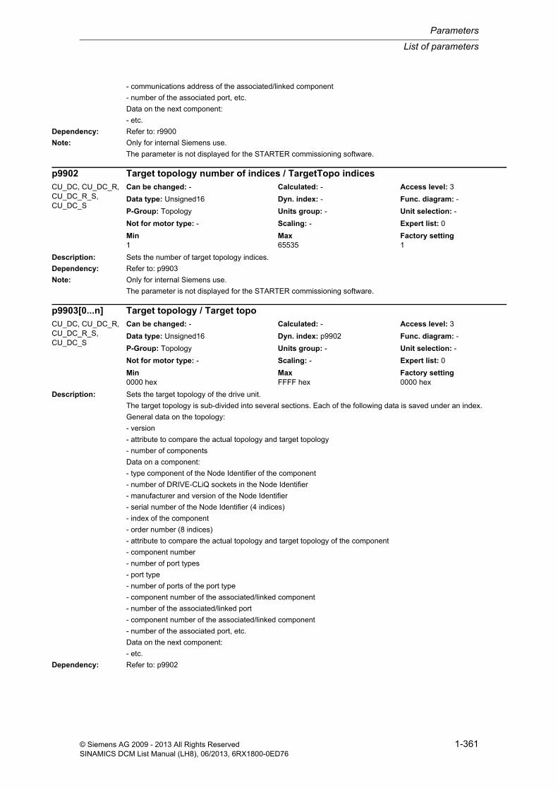
List of parameters
Parameters
1-361© Siemens AG 2009 - 2013 All Rights ReservedSINAMICS DCM List Manual (LH8), 06/2013, 6RX1800-0ED76
- communications address of the associated/linked component
- number of the associated port, etc.
Data on the next component:
- etc.
Dependency: Refer to: r9900
Note: Only for internal Siemens use.
The parameter is not displayed for the STARTER commissioning software.
Description: Sets the number of target topology indices.
Dependency: Refer to: p9903
Note: Only for internal Siemens use.
The parameter is not displayed for the STARTER commissioning software.
Description: Sets the target topology of the drive unit.
The target topology is sub-divided into several sections. Each of the following data is saved under an index.
General data on the topology:
- version
- attribute to compare the actual topology and target topology
- number of components
Data on a component:
- type component of the Node Identifier of the component
- number of DRIVE-CLiQ sockets in the Node Identifier
- manufacturer and version of the Node Identifier
- serial number of the Node Identifier (4 indices)
- index of the component
- order number (8 indices)
- attribute to compare the actual topology and target topology of the component
- component number
- number of port types
- port type
- number of ports of the port type
- component number of the associated/linked component
- number of the associated/linked port
- component number of the associated/linked component
- number of the associated port, etc.
Data on the next component:
- etc.
Dependency: Refer to: p9902
p9902 Target topology number of indices / TargetTopo indicesCU_DC, CU_DC_R, CU_DC_R_S, CU_DC_S
Can be changed: - Calculated: - Access level: 3
Data type: Unsigned16 Dyn. index: - Func. diagram: -
P-Group: Topology Units group: - Unit selection: -
Not for motor type: - Scaling: - Expert list: 0
Min Max Factory setting 1 65535 1
p9903[0...n] Target topology / Target topoCU_DC, CU_DC_R, CU_DC_R_S, CU_DC_S
Can be changed: - Calculated: - Access level: 3
Data type: Unsigned16 Dyn. index: p9902 Func. diagram: -
P-Group: Topology Units group: - Unit selection: -
Not for motor type: - Scaling: - Expert list: 0
Min Max Factory setting 0000 hex FFFF hex 0000 hex

Parameters
List of parameters
1-362 © Siemens AG 2009 - 2013 All Rights ReservedSINAMICS DCM List Manual (LH8), 06/2013, 6RX1800-0ED76
Note: The target topology can only be modified using the commissioning software.
The parameter is not displayed for the STARTER commissioning software.
Changes only become effective when the state of p0009 = 101 changes to 0 or 111.
Description: If, when comparing the actual topology and target topology, only error has occurred, that can be acknowledged, then using this parameter, a new comparison can be started - acknowledging the error in the target topology.
Differences that can be acknowledged:
- topology comparison, component shifted
- topology comparison, serial number of a component has been detected to be different (byte 3 = 1)
- topology comparison shows one component that is connected differently
The following parameter values are available:
p9904 = 1 --> the procedure is started.
p9904 = 0 after starting --> the procedure has been successfully completed.
p9904 = 1 after starting --> the procedure has not been successfully completed.
The possible causes for an unsuccessful procedure are located in bytes 4, 3, 2.
Byte 2:
Number of structural differences.
Byte 3:
Number of differences that can be acknowledged (p9904).
Byte 4:
Number of differences. These differences can be resolved as follows:
- sets the topology comparison (p9906 or p9907/p9908).
- change over the actual topology.
The appropriate action should be selected corresponding to the message that is displayed/output.
Note: In order to permanently accept the acknowledgement of the fault that can be resolved, then it must be saved in a non-volatile fashion (p0977).
Description: With p9905 = 1, the serial numbers and the hardware versions of all of the components are transferred from the actual topology into the target topology and a new comparison is started.
For this device specialization, the components of the target topology may only differ from those of the actual topol-ogy by the serial numbers.
With p9905 = 2, the serial numbers, the hardware versions and the order numbers of all of the components are transferred from the actual topology into the target topology and a new comparison is started.
For this device specialization, the components of the target topology may only differ from those of the actual topol-ogy by the serial numbers and order numbers.
Note: p9905 is automatically set to 0 at the end of the operation.
In order to permanently accept the data, it is necessary to save in a non-volatile fashion (p0977).
p9904 Topology comparison acknowledge differences / Topo_compare acknCU_DC, CU_DC_R, CU_DC_R_S, CU_DC_S
Can be changed: C1(1) Calculated: - Access level: 3
Data type: Unsigned32 Dyn. index: - Func. diagram: -
P-Group: Topology Units group: - Unit selection: -
Not for motor type: - Scaling: - Expert list: 1
Min Max Factory setting 0000 hex FFFF FFFF hex 0000 hex
p9905 Device specialization / SpecializationCU_DC, CU_DC_R, CU_DC_R_S, CU_DC_S
Can be changed: C1(1) Calculated: - Access level: 3
Data type: Unsigned16 Dyn. index: - Func. diagram: -
P-Group: Topology Units group: - Unit selection: -
Not for motor type: - Scaling: - Expert list: 1
Min Max Factory setting 0 2 0

List of parameters
Parameters
1-363© Siemens AG 2009 - 2013 All Rights ReservedSINAMICS DCM List Manual (LH8), 06/2013, 6RX1800-0ED76
Description: Sets the type of comparison between the actual topology and target topology.
The comparison is started by setting the required value.
Value: 0: High: Compares the complete electronic rating plate1: Average: Compares the component type and the Order number2: Low: Compares the component type3: Minimum: Compares the component class99: Topology has different comparison stages
Note: The electronic rating plate comprises the following data:
- component type (e.g. "SMC20")
- Order No. (e.g. "6SL3055-0AA0-5BA0")
- manufacturer (e.g. SIEMENS)
- hardware version (e.g. "A")
- Serial No. (e.g. "T-P30050495")
When comparing the topology, the following data is compared in the target and actual topologies:
p9906 = 0: Component type, Order No., Hardware version, Manufacturer, Serial No.
p9906 = 1: Component type, Order No.
p9906 = 2: Component type
p9906 = 3: Component class (e.g. Sensor Module or Motor Module)
Description: Enters the number of the component where the setting of how the actual topology should be compared to the target topology should be changed.
Dependency: Refer to: p9908
Description: Sets the type of comparison of a component in the target topology with the actual topology.
The comparison is started by setting the required value.
Value: 0: High: Compares the complete electronic rating plate1: Average: Compares the component type and the Order number2: Low: Compares the component type3: Minimum: Compares the component class99: Topology has different comparison stages
Dependency: Refer to: p9907
p9906 Topology comparison comparison stage of all components / Topo_cmpr tot compCU_DC, CU_DC_R, CU_DC_R_S, CU_DC_S
Can be changed: C1(1) Calculated: - Access level: 3
Data type: Integer16 Dyn. index: - Func. diagram: -
P-Group: Topology Units group: - Unit selection: -
Not for motor type: - Scaling: - Expert list: 1
Min Max Factory setting 0 99 0
p9907 Topology comparison comparison stage of the component number / Topo_cmpr comp_no
CU_DC, CU_DC_R, CU_DC_R_S, CU_DC_S
Can be changed: C1(1) Calculated: - Access level: 3
Data type: Unsigned8 Dyn. index: - Func. diagram: -
P-Group: Topology Units group: - Unit selection: -
Not for motor type: - Scaling: - Expert list: 1
Min Max Factory setting 0 199 0
p9908 Topology comparison comparison stage of a component / Topo_cmpr 1 compCU_DC, CU_DC_R, CU_DC_R_S, CU_DC_S
Can be changed: C1(1) Calculated: - Access level: 3
Data type: Integer16 Dyn. index: - Func. diagram: -
P-Group: Topology Units group: - Unit selection: -
Not for motor type: - Scaling: - Expert list: 1
Min Max Factory setting 0 99 0

Parameters
List of parameters
1-364 © Siemens AG 2009 - 2013 All Rights ReservedSINAMICS DCM List Manual (LH8), 06/2013, 6RX1800-0ED76
Note: The electronic rating plate comprises the following data:
- component type (e.g. "SMC20")
- Order No. (e.g. "6SL3055-0AA0-5BA0")
- manufacturer (e.g. SIEMENS)
- hardware version (e.g. "A")
- Serial No. (e.g. "T-P30050495")
When comparing the topology, the following data is compared in the target and actual topologies:
p9908 = 0: Component type, Order No., Hardware version, Manufacturer, Serial No.
p9908 = 1: Component type, Order No.
p9908 = 2: Component type
p9908 = 3: Component class (e.g. Sensor Module or Motor Module)
Description: For p9909 = 1, the serial number and the hardware version of the new replaced component is automatically trans-ferred from the actual topology into the target topology and then saved in a non-volatile fashion.
For the components that have been replaced, the electronic rating plate must match as far as the following data is concerned:
- component type (e.g. "SMC20")
- Order No. (e.g. "6SL3055-0AA0-5BA0")
For p9909 = 0, serial numbers and hardware versions are not automatically transferred. In this case, the transfer must be made using p9904.
Dependency: Refer to: p9904, p9905
Note: The modified target topology is automatically saved in a non-volatile fashion when the drive object runs-up (e.g. after a POWER ON).
Special case for Control Unit and option slot modules:
When replacing these components, independent of p9909, the serial number and hardware version are automati-cally transferred and saved in a non-volatile fashion.
Description: Transfer additional inserted DRIVE-CLiQ components into the target topology and add the appropriate drive objects to the project.
Value: 0: No selection1: Transfer components
Description: Only for internal Siemens service purposes.
p9909 Topology comparison component replacement / Topo_cmpr replaceCU_DC, CU_DC_R, CU_DC_R_S, CU_DC_S
Can be changed: C1(1) Calculated: - Access level: 3
Data type: Unsigned8 Dyn. index: - Func. diagram: -
P-Group: Topology Units group: - Unit selection: -
Not for motor type: - Scaling: - Expert list: 1
Min Max Factory setting 0 1 1
p9910 Transfer additional components into the target topology / Transfer compCU_DC, CU_DC_R, CU_DC_R_S, CU_DC_S
Can be changed: C1(1) Calculated: - Access level: 1
Data type: Integer16 Dyn. index: - Func. diagram: -
P-Group: Topology Units group: - Unit selection: -
Not for motor type: - Scaling: - Expert list: 1
Min Max Factory setting 0 1 0
p9915 DRIVE-CLiQ data transfer error shutdown threshold master / DQ fault masterCU_DC, CU_DC_R, CU_DC_R_S, CU_DC_S
Can be changed: C1(1) Calculated: - Access level: 4
Data type: Unsigned32 Dyn. index: - Func. diagram: -
P-Group: Topology Units group: - Unit selection: -
Not for motor type: - Scaling: - Expert list: 1
Min Max Factory setting 0000 hex 0007 07FF hex 0007 02FF hex

List of parameters
Parameters
1-365© Siemens AG 2009 - 2013 All Rights ReservedSINAMICS DCM List Manual (LH8), 06/2013, 6RX1800-0ED76
Description: Only for internal Siemens service purposes.
Description: Enters the license key for this drive unit.
Example of the license key:
EACZ-QBCA = 69 65 67 90 45 81 66 67 65 dec (ASCII characters)
Index 0 = license key character 1 (e.g. 69 dec)
Index 1 = license key character 2 (e.g. 65 dec)
...
Index 8 = license key character 9 (e.g. 65 dec)
Index 9 = license key character 10 (e.g. 0 dec)
...
Dependency: Refer to: r7843, p9921
Notice: An ASCII table (excerpt) can be found, for example, in the appendix to the List Manual.
With the STARTER commissioning software, ASCII characters are not entered coded, i.e. the characters of the license key can be entered as printed in the Certificate of License. In this case, STARTER codes the characters.
Note: For an invalid license key, all the indices have the value 0 dec.
Only the ASCII characters contained in a license key can be entered ("1" to "9", "A" to "H", "K" to "N", "P" to "Z" as well as "-").
When manually changing p9920[x] to the value 0 dec, all the values of all the following indices are also set to 0 dec.
After entering the license key, the license key must be activated (p9921).
If the licensing is not adequate, then the following alarm is displayed together with LED:
- A13000 --> licensing not sufficient
- LED READY --> flashes green/red with 0.5 Hz
Description: Activates the entered license key.
The following is executed when activating the license key.
- the checksum of the entered license key is checked.
- the entered license key is saved in a non-volatile fashion on the memory card.
- re-enter the license key.
Value: 0: Inactive1: Activate start license key
p9916 DRIVE-CLiQ data transfer error shutdown threshold slave / DQ fault slaveCU_DC, CU_DC_R, CU_DC_R_S, CU_DC_S
Can be changed: C1(1) Calculated: - Access level: 4
Data type: Unsigned32 Dyn. index: - Func. diagram: -
P-Group: Topology Units group: - Unit selection: -
Not for motor type: - Scaling: - Expert list: 1
Min Max Factory setting 0000 hex 0007 07FF hex 0007 02FF hex
p9920[0...99] Licensing enter license key / Enter license keyCU_DC, CU_DC_R, CU_DC_R_S, CU_DC_S
Can be changed: U, T Calculated: - Access level: 2
Data type: Unsigned8 Dyn. index: - Func. diagram: -
P-Group: - Units group: - Unit selection: -
Not for motor type: - Scaling: - Expert list: 1
Min Max Factory setting - - -
p9921 Licensing activate license key / Act license keyCU_DC, CU_DC_R, CU_DC_R_S, CU_DC_S
Can be changed: U, T Calculated: - Access level: 2
Data type: Integer16 Dyn. index: - Func. diagram: -
P-Group: - Units group: - Unit selection: -
Not for motor type: - Scaling: - Expert list: 1
Min Max Factory setting 0 1 0

Parameters
List of parameters
1-366 © Siemens AG 2009 - 2013 All Rights ReservedSINAMICS DCM List Manual (LH8), 06/2013, 6RX1800-0ED76
Dependency: Refer to: p9920
Note: Before activation, the license key entered using parameter p9920 is checked. If this check identifies an error, acti-vation is rejected. In this case, writing a 1 to p9921 is rejected.
When the license key has been activated, p9921 is automatically set to 0.
Description: Displays the directory and name of the file whose status as shipped from the factory was identified as impermissi-ble.
Dependency: Refer to: r9926
Note: The directory and name of the file is displayed in the ASCII code.
Description: Displays the status when the firmware is checked when the system is booted.
0: Firmware not yet checked.
1: Check running.
2: Check successfully completed.
3: Check indicates an error.
Dependency: Refer to: r9925
Description: Only for service purposes.
Index: [0] = System logbook stage (0: Not active)[1] = COM2/COM1 (0: COM2, 1: COM1)[2] = Activate file write (0: Not active)[3] = Display time stamp (0: Not displayed)[4...7] = Reserved[8] = System logbook file size (stages, each 10 kB)
Notice: Before powering down the Control Unit, ensure that the system logbook is switched out (p9930[0] = 0).
If writing to the file is activated (p9930[2] = 1), writing to the file must be de-activated again before switching off the Control Unit (p9930[2] = 0) in order to ensure that the system logbook has been completely written to the file.
r9925[0...99] Firmware file incorrect / FW file incorrCU_DC, CU_DC_R, CU_DC_R_S, CU_DC_S
Can be changed: - Calculated: - Access level: 2
Data type: Unsigned8 Dyn. index: - Func. diagram: -
P-Group: - Units group: - Unit selection: -
Not for motor type: - Scaling: - Expert list: 1
Min Max Factory setting - - -
r9926 Firmware check status / FW check statusCU_DC, CU_DC_R, CU_DC_R_S, CU_DC_S
Can be changed: - Calculated: - Access level: 2
Data type: Unsigned8 Dyn. index: - Func. diagram: -
P-Group: - Units group: - Unit selection: -
Not for motor type: - Scaling: - Expert list: 1
Min Max Factory setting - - -
p9930[0...8] System logbook activation / SYSLOG activationCU_DC, CU_DC_R, CU_DC_R_S, CU_DC_S
Can be changed: U, T Calculated: - Access level: 4
Data type: Unsigned8 Dyn. index: - Func. diagram: -
P-Group: - Units group: - Unit selection: -
Not for motor type: - Scaling: - Expert list: 1
Min Max Factory setting 0 255 0

List of parameters
Parameters
1-367© Siemens AG 2009 - 2013 All Rights ReservedSINAMICS DCM List Manual (LH8), 06/2013, 6RX1800-0ED76
Description: Only for service purposes.
Description: Only for service purposes.
Description: Display and binector output for a delay after POWER ON.
After power-on, binector output r9935.0 is set with the start of the first sampling time and is again reset after approx. 100 ms.
Description: Displays the error counter for the individual DRIVE-CLiQ connections/cables.
r9936[0]: sum of the error counter for all connections
r9936[1]: not used
r9936[2]: error counter for the feeder cable to DRIVE-CLiQ components with component number 2
...
r9936[199]: error counter for the feeder cable to DRIVE-CLiQ components with component number 199
The feeder cable is the DRIVE-CLiQ cable that is connected to a component in the direction of the Control Unit.
Dependency: Refer to: p9937, p9938
p9931[0...129] System logbook module selection / SYSLOG mod selectCU_DC, CU_DC_R, CU_DC_R_S, CU_DC_S
Can be changed: U, T Calculated: - Access level: 4
Data type: Unsigned32 Dyn. index: - Func. diagram: -
P-Group: - Units group: - Unit selection: -
Not for motor type: - Scaling: - Expert list: 1
Min Max Factory setting 0000 hex FFFF FFFF hex 0000 hex
p9932 Save system logbook EEPROM / SYSLOG EEPROM saveCU_DC, CU_DC_R, CU_DC_R_S, CU_DC_S
Can be changed: U, T Calculated: - Access level: 4
Data type: Unsigned8 Dyn. index: - Func. diagram: -
P-Group: - Units group: - Unit selection: -
Not for motor type: - Scaling: - Expert list: 1
Min Max Factory setting 0 255 0
r9935.0 BO: POWER ON delay signal / POWER ON t_delayCU_DC, CU_DC_R, CU_DC_R_S, CU_DC_S
Can be changed: - Calculated: - Access level: 3
Data type: Unsigned8 Dyn. index: - Func. diagram: -
P-Group: - Units group: - Unit selection: -
Not for motor type: - Scaling: - Expert list: 1
Min Max Factory setting - - -
Bit field: Bit Signal name 1 signal 0 signal FP00 POWER ON delay signal High Low -
r9936[0...199] DRIVE-CLiQ diagnostic error counter connection / DQdiag err counterCU_DC, CU_DC_R, CU_DC_R_S, CU_DC_S
Can be changed: - Calculated: - Access level: 4
Data type: Integer32 Dyn. index: - Func. diagram: -
P-Group: - Units group: - Unit selection: -
Not for motor type: - Scaling: - Expert list: 1
Min Max Factory setting - - -

Parameters
List of parameters
1-368 © Siemens AG 2009 - 2013 All Rights ReservedSINAMICS DCM List Manual (LH8), 06/2013, 6RX1800-0ED76
Description: Sets the configuration for the DRIVE-CLiQ diagnostics (error counter r9936).
Using this function, connections and cables of DRIVE-CLiQ connections can be checked for transfer errors. The error counter is evaluated in the PHY blocks involved.
Dependency: Refer to: r9936, p9938
Note: Re bit 00:
To activate this function, p9938 must be set to 0 (inactive).
After changing the error counter (r9936), an appropriate alarm is output.
The alarm automatically disappears after 5 seconds.
Re bit 08:
With p9937.8 = 1, the error counters are reset (r9936[0...199]).
After the reset, p9937.8 is automatically set to 0.
Description: Sets the configuration for the DRIVE-CLiQ detailed diagnostics (r9943).
Using the detailed diagnostics, it is possible to investigate data transfer errors on an individual connection, selected using p9942.
Value: 0: Inactive1: Sum send and receive errors2: Only send errors3: Only receive errors4: Siemens internal5: Siemens internal6: Siemens internal
Dependency: The functions in p9938 can only be set for p9937.0 = 0.
Refer to: r9936, p9937, p9939, p9942
Notice: If value = 0:
- detailed diagnostics is inactive.
- the error counter is active (r9936).
Re value > 0:
- the error counter is inactive (r9936).
- the detailed diagnostics as configured is active (r9943).
p9937 DRIVE-CLiQ diagnostic configuration / DQ diag configCU_DC, CU_DC_R, CU_DC_R_S, CU_DC_S
Can be changed: U, T Calculated: - Access level: 4
Data type: Unsigned16 Dyn. index: - Func. diagram: -
P-Group: - Units group: - Unit selection: -
Not for motor type: - Scaling: - Expert list: 1
Min Max Factory setting - - 0000 0000 0000 0000 bin
Bit field: Bit Signal name 1 signal 0 signal FP00 Alarm for connection error Yes No -08 Reset error counter Yes No -
p9938 DRIVE-CLiQ detailed diagnostics configuration / DQ diag configCU_DC, CU_DC_R, CU_DC_R_S, CU_DC_S
Can be changed: U, T Calculated: - Access level: 4
Data type: Integer16 Dyn. index: - Func. diagram: -
P-Group: - Units group: - Unit selection: -
Not for motor type: - Scaling: - Expert list: 1
Min Max Factory setting 0 6 0

List of parameters
Parameters
1-369© Siemens AG 2009 - 2013 All Rights ReservedSINAMICS DCM List Manual (LH8), 06/2013, 6RX1800-0ED76
Description: Sets the time interval for recording the error counter in r9943.
Dependency: Refer to: r9936, p9938, p9942, r9943
Description: For p9941 =1, the serial numbers of all components in the target topology are deleted (zero is written).
Through activation and de-activation this enables the actual topology components to be newly assigned to the tar-get topology components.
Note: p9941 is automatically set to 0 at the end of the operation.
A warm restart is triggered automatically after p0009 = 0.
Description: Sets the component, whose feeder cable is monitored for data transfer errors.
The feeder cable is the DRIVE-CLiQ cable that is connected to a component in the direction of the Control Unit.
Errors that have occurred in the selected time interval (p9939) can be read-out from r9943.
Dependency: Refer to: r9936, p9938, p9939, r9943
Description: Displays the connection errors of the individual connection that have occurred within the time interval (p9939).
The detailed diagnostics for the individual connection is activated via p9938 > 0 and is selected via p9942.
Dependency: Refer to: r9936, p9938, p9939, p9942
p9939 DRIVE-CLiQ detailed diagnostics time interval / DQ detail t_intervCU_DC, CU_DC_R, CU_DC_R_S, CU_DC_S
Can be changed: U, T Calculated: - Access level: 4
Data type: FloatingPoint32 Dyn. index: - Func. diagram: -
P-Group: - Units group: - Unit selection: -
Not for motor type: - Scaling: - Expert list: 1
Min Max Factory setting 1 [s] 3600 [s] 1 [s]
p9941 Target topology feature delete all components / Feature deleteCU_DC, CU_DC_R, CU_DC_R_S, CU_DC_S
Can be changed: C1(1) Calculated: - Access level: 3
Data type: Unsigned32 Dyn. index: - Func. diagram: -
P-Group: Topology Units group: - Unit selection: -
Not for motor type: - Scaling: - Expert list: 0
Min Max Factory setting 0 1 0
p9942 DRIVE-CLiQ detailed diagnostics select individual connection / DQ detail connCU_DC, CU_DC_R, CU_DC_R_S, CU_DC_S
Can be changed: U, T Calculated: - Access level: 4
Data type: Unsigned16 Dyn. index: - Func. diagram: -
P-Group: - Units group: - Unit selection: -
Not for motor type: - Scaling: - Expert list: 1
Min Max Factory setting 0 199 0
r9943 DRIVE-CLiQ detailed diagn. individual connection error counter / DQ det err counterCU_DC, CU_DC_R, CU_DC_R_S, CU_DC_S
Can be changed: - Calculated: - Access level: 4
Data type: Integer32 Dyn. index: - Func. diagram: -
P-Group: - Units group: - Unit selection: -
Not for motor type: - Scaling: - Expert list: 1
Min Max Factory setting - - -

Parameters
List of parameters
1-370 © Siemens AG 2009 - 2013 All Rights ReservedSINAMICS DCM List Manual (LH8), 06/2013, 6RX1800-0ED76
Description: Displays the measured system utilization.
The higher the value displayed, the higher the system utilization.
Index: [0] = Computing time utilization (min)[1] = Computing time utilization (averaged)[2] = Computing time utilization (max)[3] = Largest total utilization (min)[4] = Largest total utilization (averaged)[5] = Largest total utilization (max)[6] = Reserved[7] = Reserved
Dependency: Refer to: r9976, r9979, r9980, r9981
Note: Re index 3 ... 5:
The total utilizations are determined using all sampling times used. The largest total utilizations are mapped here. The sampling time with the largest total utilization is displayed in r9979.
Total utilization:
Computing time load of sampling time involved including load from higher-priority sampling times (interrupts).
Description: Displays the system utilization.
If the utilization is greater than 100%, fault F01054 is output.
Index: [0] = Reserved[1] = Computing time utilization[2] = Reserved[3] = Reserved[4] = Reserved[5] = Largest total utilization[6] = Reserved[7] = Reserved
Dependency: Refer to: r9979, r9980
Note: Re index 1:
The value shows the total computing time load of the system.
Re index 5:
The total utilization is determined using all sampling times used. The largest total utilization is mapped here. The sampling time with the largest total utilization is displayed in r9979.
Total utilization:
Computing time load of sampling time involved including load from higher-priority sampling times (interrupts).
r9975[0...7] System utilization measured / Sys util measCU_DC, CU_DC_R, CU_DC_R_S, CU_DC_S
Can be changed: - Calculated: - Access level: 4
Data type: FloatingPoint32 Dyn. index: - Func. diagram: -
P-Group: - Units group: - Unit selection: -
Not for motor type: - Scaling: - Expert list: 1
Min Max Factory setting - [%] - [%] - [%]
r9976[0...7] System utilization / Sys utilCU_DC, CU_DC_R, CU_DC_R_S, CU_DC_S
Can be changed: - Calculated: - Access level: 3
Data type: FloatingPoint32 Dyn. index: - Func. diagram: -
P-Group: - Units group: - Unit selection: -
Not for motor type: - Scaling: - Expert list: 1
Min Max Factory setting - [%] - [%] - [%]
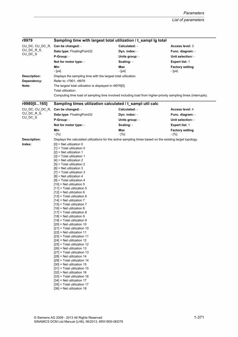
List of parameters
Parameters
1-371© Siemens AG 2009 - 2013 All Rights ReservedSINAMICS DCM List Manual (LH8), 06/2013, 6RX1800-0ED76
Description: Displays the sampling time with the largest total utilization.
Dependency: Refer to: r7901, r9976
Note: The largest total utilization is displayed in r9976[5].
Total utilization:
Computing time load of sampling time involved including load from higher-priority sampling times (interrupts).
Description: Displays the calculated utilizations for the active sampling times based on the existing target topology.
Index: [0] = Net utilization 0[1] = Total utilization 0[2] = Net utilization 1[3] = Total utilization 1[4] = Net utilization 2[5] = Total utilization 2[6] = Net utilization 3[7] = Total utilization 3[8] = Net utilization 4[9] = Total utilization 4[10] = Net utilization 5[11] = Total utilization 5[12] = Net utilization 6[13] = Total utilization 6[14] = Net utilization 7[15] = Total utilization 7[16] = Net utilization 8[17] = Total utilization 8[18] = Net utilization 9[19] = Total utilization 9[20] = Net utilization 10[21] = Total utilization 10[22] = Net utilization 11[23] = Total utilization 11[24] = Net utilization 12[25] = Total utilization 12[26] = Net utilization 13[27] = Total utilization 13[28] = Net utilization 14[29] = Total utilization 14[30] = Net utilization 15[31] = Total utilization 15[32] = Net utilization 16[33] = Total utilization 16[34] = Net utilization 17[35] = Total utilization 17[36] = Net utilization 18
r9979 Sampling time with largest total utilization / t_sampl lg totalCU_DC, CU_DC_R, CU_DC_R_S, CU_DC_S
Can be changed: - Calculated: - Access level: 3
Data type: FloatingPoint32 Dyn. index: - Func. diagram: -
P-Group: - Units group: - Unit selection: -
Not for motor type: - Scaling: - Expert list: 1
Min Max Factory setting - [µs] - [µs] - [µs]
r9980[0...165] Sampling times utilization calculated / t_sampl util calcCU_DC, CU_DC_R, CU_DC_R_S, CU_DC_S
Can be changed: - Calculated: - Access level: 4
Data type: FloatingPoint32 Dyn. index: - Func. diagram: -
P-Group: - Units group: - Unit selection: -
Not for motor type: - Scaling: - Expert list: 1
Min Max Factory setting - [%] - [%] - [%]

Parameters
List of parameters
1-372 © Siemens AG 2009 - 2013 All Rights ReservedSINAMICS DCM List Manual (LH8), 06/2013, 6RX1800-0ED76
[37] = Total utilization 18[38] = Net utilization 19[39] = Total utilization 19[40] = Net utilization 20[41] = Total utilization 20[42] = Net utilization 21[43] = Total utilization 21[44] = Net utilization 22[45] = Total utilization 22[46] = Net utilization 23[47] = Total utilization 23[48] = Net utilization 24[49] = Total utilization 24[50] = Net utilization 25[51] = Total utilization 25[52] = Net utilization 26[53] = Total utilization 26[54] = Net utilization 27[55] = Total utilization 27[56] = Net utilization 28[57] = Total utilization 28[58] = Net utilization 29[59] = Total utilization 29[60] = Net utilization 30[61] = Total utilization 30[62] = Net utilization 31[63] = Total utilization 31[64] = Net utilization 32[65] = Total utilization 32[66] = Net utilization 33[67] = Total utilization 33[68] = Net utilization 34[69] = Total utilization 34[70] = Net utilization 35[71] = Total utilization 35[72] = Net utilization 36[73] = Total utilization 36[74] = Net utilization 37[75] = Total utilization 37[76] = Net utilization 38[77] = Total utilization 38[78] = Net utilization 39[79] = Total utilization 39[80] = Net utilization 40[81] = Total utilization 40[82] = Net utilization 41[83] = Total utilization 41[84] = Net utilization 42[85] = Total utilization 42[86] = Net utilization 43[87] = Total utilization 43[88] = Net utilization 44[89] = Total utilization 44[90] = Net utilization 45[91] = Total utilization 45[92] = Net utilization 46[93] = Total utilization 46[94] = Net utilization 47[95] = Total utilization 47[96] = Net utilization 48[97] = Total utilization 48[98] = Net utilization 49[99] = Total utilization 49[100] = Net utilization 50

List of parameters
Parameters
1-373© Siemens AG 2009 - 2013 All Rights ReservedSINAMICS DCM List Manual (LH8), 06/2013, 6RX1800-0ED76
[101] = Total utilization 50[102] = Net utilization 51[103] = Total utilization 51[104] = Net utilization 52[105] = Total utilization 52[106] = Net utilization 53[107] = Total utilization 53[108] = Net utilization 54[109] = Total utilization 54[110] = Net utilization 55[111] = Total utilization 55[112] = Net utilization 56[113] = Total utilization 56[114] = Net utilization 57[115] = Total utilization 57[116] = Net utilization 58[117] = Total utilization 58[118] = Net utilization 59[119] = Total utilization 59[120] = Net utilization 60[121] = Total utilization 60[122] = Net utilization 61[123] = Total utilization 61[124] = Net utilization 62[125] = Total utilization 62[126] = Net utilization 63[127] = Total utilization 63[128] = Net utilization 64[129] = Total utilization 64[130] = Net utilization 65[131] = Total utilization 65[132] = Net utilization 66[133] = Total utilization 66[134] = Net utilization 67[135] = Total utilization 67[136] = Net utilization 68[137] = Total utilization 68[138] = Net utilization 69[139] = Total utilization 69[140] = Net utilization 70[141] = Total utilization 70[142] = Net utilization 71[143] = Total utilization 71[144] = Net utilization 72[145] = Total utilization 72[146] = Net utilization 73[147] = Total utilization 73[148] = Net utilization 74[149] = Total utilization 74[150] = Net utilization 75[151] = Total utilization 75[152] = Net utilization 76[153] = Total utilization 76[154] = Net utilization 77[155] = Total utilization 77[156] = Net utilization 78[157] = Total utilization 78[158] = Net utilization 79[159] = Total utilization 79[160] = Net utilization 80[161] = Total utilization 80[162] = Net utilization 81[163] = Total utilization 81
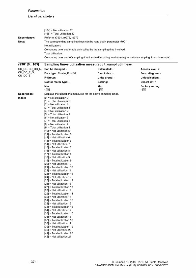
Parameters
List of parameters
1-374 © Siemens AG 2009 - 2013 All Rights ReservedSINAMICS DCM List Manual (LH8), 06/2013, 6RX1800-0ED76
[164] = Net utilization 82[165] = Total utilization 82
Dependency: Refer to: r7901, r9976, r9979
Note: The corresponding sampling times can be read out in parameter r7901.
Net utilization:
Computing time load that is only called by the sampling time involved.
Total utilization:
Computing time load of sampling time involved including load from higher-priority sampling times (interrupts).
Description: Displays the utilizations measured for the active sampling times.
Index: [0] = Net utilization 0[1] = Total utilization 0[2] = Net utilization 1[3] = Total utilization 1[4] = Net utilization 2[5] = Total utilization 2[6] = Net utilization 3[7] = Total utilization 3[8] = Net utilization 4[9] = Total utilization 4[10] = Net utilization 5[11] = Total utilization 5[12] = Net utilization 6[13] = Total utilization 6[14] = Net utilization 7[15] = Total utilization 7[16] = Net utilization 8[17] = Total utilization 8[18] = Net utilization 9[19] = Total utilization 9[20] = Net utilization 10[21] = Total utilization 10[22] = Net utilization 11[23] = Total utilization 11[24] = Net utilization 12[25] = Total utilization 12[26] = Net utilization 13[27] = Total utilization 13[28] = Net utilization 14[29] = Total utilization 14[30] = Net utilization 15[31] = Total utilization 15[32] = Net utilization 16[33] = Total utilization 16[34] = Net utilization 17[35] = Total utilization 17[36] = Net utilization 18[37] = Total utilization 18[38] = Net utilization 19[39] = Total utilization 19[40] = Net utilization 20[41] = Total utilization 20[42] = Net utilization 21
r9981[0...165] Sampling times utilization measured / t_sampl util measCU_DC, CU_DC_R, CU_DC_R_S, CU_DC_S
Can be changed: - Calculated: - Access level: 4
Data type: FloatingPoint32 Dyn. index: - Func. diagram: -
P-Group: - Units group: - Unit selection: -
Not for motor type: - Scaling: - Expert list: 1
Min Max Factory setting - [%] - [%] - [%]

List of parameters
Parameters
1-375© Siemens AG 2009 - 2013 All Rights ReservedSINAMICS DCM List Manual (LH8), 06/2013, 6RX1800-0ED76
[43] = Total utilization 21[44] = Net utilization 22[45] = Total utilization 22[46] = Net utilization 23[47] = Total utilization 23[48] = Net utilization 24[49] = Total utilization 24[50] = Net utilization 25[51] = Total utilization 25[52] = Net utilization 26[53] = Total utilization 26[54] = Net utilization 27[55] = Total utilization 27[56] = Net utilization 28[57] = Total utilization 28[58] = Net utilization 29[59] = Total utilization 29[60] = Net utilization 30[61] = Total utilization 30[62] = Net utilization 31[63] = Total utilization 31[64] = Net utilization 32[65] = Total utilization 32[66] = Net utilization 33[67] = Total utilization 33[68] = Net utilization 34[69] = Total utilization 34[70] = Net utilization 35[71] = Total utilization 35[72] = Net utilization 36[73] = Total utilization 36[74] = Net utilization 37[75] = Total utilization 37[76] = Net utilization 38[77] = Total utilization 38[78] = Net utilization 39[79] = Total utilization 39[80] = Net utilization 40[81] = Total utilization 40[82] = Net utilization 41[83] = Total utilization 41[84] = Net utilization 42[85] = Total utilization 42[86] = Net utilization 43[87] = Total utilization 43[88] = Net utilization 44[89] = Total utilization 44[90] = Net utilization 45[91] = Total utilization 45[92] = Net utilization 46[93] = Total utilization 46[94] = Net utilization 47[95] = Total utilization 47[96] = Net utilization 48[97] = Total utilization 48[98] = Net utilization 49[99] = Total utilization 49[100] = Net utilization 50[101] = Total utilization 50[102] = Net utilization 51[103] = Total utilization 51[104] = Net utilization 52[105] = Total utilization 52[106] = Net utilization 53
Parameters
List of parameters
1-376 © Siemens AG 2009 - 2013 All Rights ReservedSINAMICS DCM List Manual (LH8), 06/2013, 6RX1800-0ED76
[107] = Total utilization 53[108] = Net utilization 54[109] = Total utilization 54[110] = Net utilization 55[111] = Total utilization 55[112] = Net utilization 56[113] = Total utilization 56[114] = Net utilization 57[115] = Total utilization 57[116] = Net utilization 58[117] = Total utilization 58[118] = Net utilization 59[119] = Total utilization 59[120] = Net utilization 60[121] = Total utilization 60[122] = Net utilization 61[123] = Total utilization 61[124] = Net utilization 62[125] = Total utilization 62[126] = Net utilization 63[127] = Total utilization 63[128] = Net utilization 64[129] = Total utilization 64[130] = Net utilization 65[131] = Total utilization 65[132] = Net utilization 66[133] = Total utilization 66[134] = Net utilization 67[135] = Total utilization 67[136] = Net utilization 68[137] = Total utilization 68[138] = Net utilization 69[139] = Total utilization 69[140] = Net utilization 70[141] = Total utilization 70[142] = Net utilization 71[143] = Total utilization 71[144] = Net utilization 72[145] = Total utilization 72[146] = Net utilization 73[147] = Total utilization 73[148] = Net utilization 74[149] = Total utilization 74[150] = Net utilization 75[151] = Total utilization 75[152] = Net utilization 76[153] = Total utilization 76[154] = Net utilization 77[155] = Total utilization 77[156] = Net utilization 78[157] = Total utilization 78[158] = Net utilization 79[159] = Total utilization 79[160] = Net utilization 80[161] = Total utilization 80[162] = Net utilization 81[163] = Total utilization 81[164] = Net utilization 82[165] = Total utilization 82
Dependency: Refer to: r7901, r9975, r9980
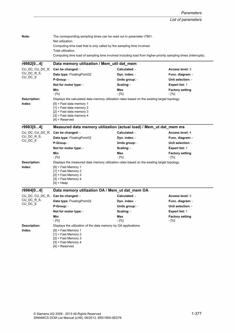
List of parameters
Parameters
1-377© Siemens AG 2009 - 2013 All Rights ReservedSINAMICS DCM List Manual (LH8), 06/2013, 6RX1800-0ED76
Note: The corresponding sampling times can be read out in parameter r7901.
Net utilization:
Computing time load that is only called by the sampling time involved.
Total utilization:
Computing time load of sampling time involved including load from higher-priority sampling times (interrupts).
Description: Displays the calculated data memory utilization rates based on the existing target topology.
Index: [0] = Fast data memory 1[1] = Fast data memory 2[2] = Fast data memory 3[3] = Fast data memory 4[4] = Reserved
Description: Displays the measured data memory utilization rates based on the existing target topology.
Index: [0] = Fast Memory 1[1] = Fast Memory 2[2] = Fast Memory 3[3] = Fast Memory 4[4] = Heap
Description: Displays the utilization of the data memory by OA applications.
Index: [0] = Fast Memory 1[1] = Fast Memory 2[2] = Fast Memory 3[3] = Fast Memory 4[4] = Reserved
r9982[0...4] Data memory utilization / Mem_util dat_memCU_DC, CU_DC_R, CU_DC_R_S, CU_DC_S
Can be changed: - Calculated: - Access level: 3
Data type: FloatingPoint32 Dyn. index: - Func. diagram: -
P-Group: - Units group: - Unit selection: -
Not for motor type: - Scaling: - Expert list: 1
Min Max Factory setting - [%] - [%] - [%]
r9983[0...4] Measured data memory utilization (actual load) / Mem_ut dat_mem msCU_DC, CU_DC_R, CU_DC_R_S, CU_DC_S
Can be changed: - Calculated: - Access level: 4
Data type: FloatingPoint32 Dyn. index: - Func. diagram: -
P-Group: - Units group: - Unit selection: -
Not for motor type: - Scaling: - Expert list: 1
Min Max Factory setting - [%] - [%] - [%]
r9984[0...4] Data memory utilization OA / Mem_ut dat_mem OACU_DC, CU_DC_R, CU_DC_R_S, CU_DC_S
Can be changed: - Calculated: - Access level: 3
Data type: FloatingPoint32 Dyn. index: - Func. diagram: -
P-Group: - Units group: - Unit selection: -
Not for motor type: - Scaling: - Expert list: 1
Min Max Factory setting - [%] - [%] - [%]

Parameters
List of parameters
1-378 © Siemens AG 2009 - 2013 All Rights ReservedSINAMICS DCM List Manual (LH8), 06/2013, 6RX1800-0ED76
Description: Displays the calculated DRIVE-CLiQ system load based on the existing target topology.
The values are not made available until the RUNUP READY (800) state is adopted (see p3988).
Index 0 ... 7 corresponds to DRIVE-CLiQ socket X100 ... X107.
Description: Displays the calculated DRIVE-CLiQ bandwidth load based on the existing target topology.
The values are not made available until the RUNUP READY (800) state is adopted (see p3988).
Index 0 ... 7 corresponds to DRIVE-CLiQ socket X100 ... X107.
Description: Displays the calculated DRIVE-CLiQ DPRAM load based on the existing target topology.
The values are not made available until the RUNUP READY (800) state is adopted (see p3988).
Index 0 ... 7 corresponds to DRIVE-CLiQ socket X100 ... X107.
Description: The meaning of the parameter differs for reading and writing.
Read:
- Returns the number of memory areas monitored.
Write:
- Memory usage of a drive object: Enter drive object number
- Memory usage of the complete system: Enter value 65535
r9986[0...7] DRIVE-CLiQ system load / DQ system loadCU_DC, CU_DC_R, CU_DC_R_S, CU_DC_S
Can be changed: - Calculated: - Access level: 3
Data type: FloatingPoint32 Dyn. index: - Func. diagram: -
P-Group: - Units group: - Unit selection: -
Not for motor type: - Scaling: - Expert list: 1
Min Max Factory setting - [%] - [%] - [%]
r9987[0...7] DRIVE-CLiQ bandwidth load / DQ bandw loadCU_DC, CU_DC_R, CU_DC_R_S, CU_DC_S
Can be changed: - Calculated: - Access level: 3
Data type: FloatingPoint32 Dyn. index: - Func. diagram: -
P-Group: - Units group: - Unit selection: -
Not for motor type: - Scaling: - Expert list: 1
Min Max Factory setting - [%] - [%] - [%]
r9988[0...7] DRIVE-CLiQ DPRAM load / DQ DPRAM loadCU_DC, CU_DC_R, CU_DC_R_S, CU_DC_S
Can be changed: - Calculated: - Access level: 3
Data type: FloatingPoint32 Dyn. index: - Func. diagram: -
P-Group: - Units group: - Unit selection: -
Not for motor type: - Scaling: - Expert list: 1
Min Max Factory setting - [%] - [%] - [%]
p9990 DO memory usage actual value determination selection / Mem_use ActVal selCU_DC, CU_DC_R, CU_DC_R_S, CU_DC_S
Can be changed: U, T Calculated: - Access level: 4
Data type: Unsigned16 Dyn. index: - Func. diagram: -
P-Group: - Units group: - Unit selection: -
Not for motor type: - Scaling: - Expert list: 1
Min Max Factory setting 0 65535 0
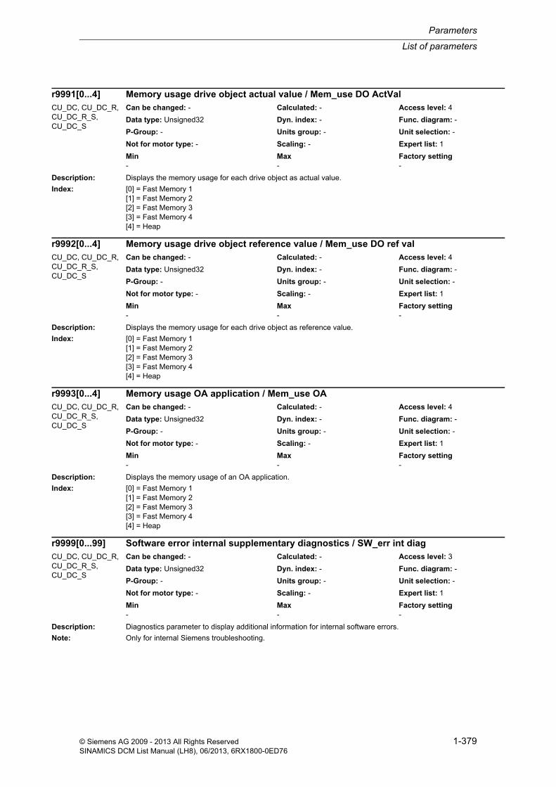
List of parameters
Parameters
1-379© Siemens AG 2009 - 2013 All Rights ReservedSINAMICS DCM List Manual (LH8), 06/2013, 6RX1800-0ED76
Description: Displays the memory usage for each drive object as actual value.
Index: [0] = Fast Memory 1[1] = Fast Memory 2[2] = Fast Memory 3[3] = Fast Memory 4[4] = Heap
Description: Displays the memory usage for each drive object as reference value.
Index: [0] = Fast Memory 1[1] = Fast Memory 2[2] = Fast Memory 3[3] = Fast Memory 4[4] = Heap
Description: Displays the memory usage of an OA application.
Index: [0] = Fast Memory 1[1] = Fast Memory 2[2] = Fast Memory 3[3] = Fast Memory 4[4] = Heap
Description: Diagnostics parameter to display additional information for internal software errors.
Note: Only for internal Siemens troubleshooting.
r9991[0...4] Memory usage drive object actual value / Mem_use DO ActValCU_DC, CU_DC_R, CU_DC_R_S, CU_DC_S
Can be changed: - Calculated: - Access level: 4
Data type: Unsigned32 Dyn. index: - Func. diagram: -
P-Group: - Units group: - Unit selection: -
Not for motor type: - Scaling: - Expert list: 1
Min Max Factory setting - - -
r9992[0...4] Memory usage drive object reference value / Mem_use DO ref valCU_DC, CU_DC_R, CU_DC_R_S, CU_DC_S
Can be changed: - Calculated: - Access level: 4
Data type: Unsigned32 Dyn. index: - Func. diagram: -
P-Group: - Units group: - Unit selection: -
Not for motor type: - Scaling: - Expert list: 1
Min Max Factory setting - - -
r9993[0...4] Memory usage OA application / Mem_use OACU_DC, CU_DC_R, CU_DC_R_S, CU_DC_S
Can be changed: - Calculated: - Access level: 4
Data type: Unsigned32 Dyn. index: - Func. diagram: -
P-Group: - Units group: - Unit selection: -
Not for motor type: - Scaling: - Expert list: 1
Min Max Factory setting - - -
r9999[0...99] Software error internal supplementary diagnostics / SW_err int diagCU_DC, CU_DC_R, CU_DC_R_S, CU_DC_S
Can be changed: - Calculated: - Access level: 3
Data type: Unsigned32 Dyn. index: - Func. diagram: -
P-Group: - Units group: - Unit selection: -
Not for motor type: - Scaling: - Expert list: 1
Min Max Factory setting - - -
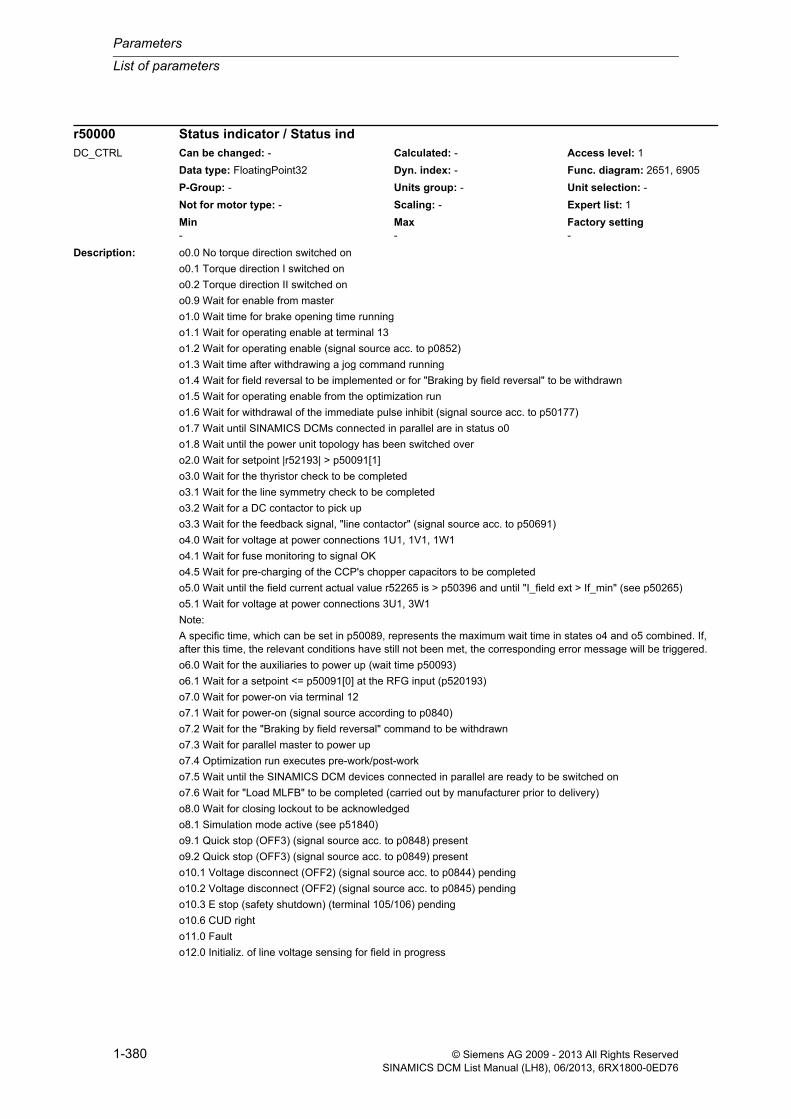
Parameters
List of parameters
1-380 © Siemens AG 2009 - 2013 All Rights ReservedSINAMICS DCM List Manual (LH8), 06/2013, 6RX1800-0ED76
Description: o0.0 No torque direction switched on
o0.1 Torque direction I switched on
o0.2 Torque direction II switched on
o0.9 Wait for enable from master
o1.0 Wait time for brake opening time running
o1.1 Wait for operating enable at terminal 13
o1.2 Wait for operating enable (signal source acc. to p0852)
o1.3 Wait time after withdrawing a jog command running
o1.4 Wait for field reversal to be implemented or for "Braking by field reversal" to be withdrawn
o1.5 Wait for operating enable from the optimization run
o1.6 Wait for withdrawal of the immediate pulse inhibit (signal source acc. to p50177)
o1.7 Wait until SINAMICS DCMs connected in parallel are in status o0
o1.8 Wait until the power unit topology has been switched over
o2.0 Wait for setpoint |r52193| > p50091[1]
o3.0 Wait for the thyristor check to be completed
o3.1 Wait for the line symmetry check to be completed
o3.2 Wait for a DC contactor to pick up
o3.3 Wait for the feedback signal, "line contactor" (signal source acc. to p50691)
o4.0 Wait for voltage at power connections 1U1, 1V1, 1W1
o4.1 Wait for fuse monitoring to signal OK
o4.5 Wait for pre-charging of the CCP's chopper capacitors to be completed
o5.0 Wait until the field current actual value r52265 is > p50396 and until "I_field ext > If_min" (see p50265)
o5.1 Wait for voltage at power connections 3U1, 3W1
Note:
A specific time, which can be set in p50089, represents the maximum wait time in states o4 and o5 combined. If, after this time, the relevant conditions have still not been met, the corresponding error message will be triggered.
o6.0 Wait for the auxiliaries to power up (wait time p50093)
o6.1 Wait for a setpoint <= p50091[0] at the RFG input (p520193)
o7.0 Wait for power-on via terminal 12
o7.1 Wait for power-on (signal source according to p0840)
o7.2 Wait for the "Braking by field reversal" command to be withdrawn
o7.3 Wait for parallel master to power up
o7.4 Optimization run executes pre-work/post-work
o7.5 Wait until the SINAMICS DCM devices connected in parallel are ready to be switched on
o7.6 Wait for "Load MLFB" to be completed (carried out by manufacturer prior to delivery)
o8.0 Wait for closing lockout to be acknowledged
o8.1 Simulation mode active (see p51840)
o9.1 Quick stop (OFF3) (signal source acc. to p0848) present
o9.2 Quick stop (OFF3) (signal source acc. to p0849) present
o10.1 Voltage disconnect (OFF2) (signal source acc. to p0844) pending
o10.2 Voltage disconnect (OFF2) (signal source acc. to p0845) pending
o10.3 E stop (safety shutdown) (terminal 105/106) pending
o10.6 CUD right
o11.0 Fault
o12.0 Initializ. of line voltage sensing for field in progress
r50000 Status indicator / Status indDC_CTRL Can be changed: - Calculated: - Access level: 1
Data type: FloatingPoint32 Dyn. index: - Func. diagram: 2651, 6905
P-Group: - Units group: - Unit selection: -
Not for motor type: - Scaling: - Expert list: 1
Min Max Factory setting - - -

List of parameters
Parameters
1-381© Siemens AG 2009 - 2013 All Rights ReservedSINAMICS DCM List Manual (LH8), 06/2013, 6RX1800-0ED76
o12.1 Initializ. of line voltage sensing for armature in progr.
o12.3 Read out data from gating modules (armature and field)
o12.4 Offset calibr. of curr. act. val. sensing being performed
o12.5 Read out data from the power unit
o12.6 Wait for second processor (TMS320) to go into normal operation
Description: Displays the motor temperature.
The temperature sensor is connected via terminal X177.53/54/55 of the CUD.
Dependency: The temperature value is only displayed when using one of the following temperature sensors:
- KTY84 (p50490 = 1): measuring range = -40 °C to +300 °C
- PT100 (p50490 = 6): measuring range = -200 °C to +300 °C
- NTC thermistor K227 (p50490 = 7): measuring range = +85 °C to +200 °C
- PT1000 (p50490 = 8): measuring range = -200 °C to +300 °C
Refer to: p50490, r52051
Note: If p50490 = 0, 2 to 5, a value of 0 is displayed.
Description: Displays the temperature of the various temperature sensors for device and modules.
Index: [0] = Temperature sensor 1[1] = Temperature sensor 2[2] = Temperature sensor 3[3] = Gating module temperature[4] = CUD Control Unit temperature
Note: Temperature sensors which are not in use return a high negative value (approx. -200 °C).
Description: Displays the values calculated for the temperature rise of the motors and the thyristors.
Index: [0] = Motor temperature rise[1] = Thyristor temperature rise
Dependency: Refer to: p50075, r52310
r50012 Motor temperature / Mot tempDC_CTRL Can be changed: - Calculated: - Access level: 1
Data type: FloatingPoint32 Dyn. index: - Func. diagram: 8030
P-Group: - Units group: - Unit selection: -
Not for motor type: - Scaling: - Expert list: 1
Min Max Factory setting - [°C] - [°C] - [°C]
r50013[0...4] Temperature sensor/Module / Temp sensor/ModDC_CTRL Can be changed: - Calculated: - Access level: 1
Data type: FloatingPoint32 Dyn. index: - Func. diagram: 8048
P-Group: - Units group: - Unit selection: -
Not for motor type: - Scaling: - Expert list: 1
Min Max Factory setting - [°C] - [°C] - [°C]
r50014[0...1] Temperature rises calculated / Temp rise calcDC_CTRL Can be changed: - Calculated: - Access level: 1
Data type: FloatingPoint32 Dyn. index: - Func. diagram: 8038, 8042
P-Group: - Units group: - Unit selection: -
Not for motor type: - Scaling: PERCENT Expert list: 1
Min Max Factory setting - [%] - [%] - [%]

Parameters
List of parameters
1-382 © Siemens AG 2009 - 2013 All Rights ReservedSINAMICS DCM List Manual (LH8), 06/2013, 6RX1800-0ED76
Description: Displays the phase-to-phase line voltage in the armature circuit (rms value).
Description: Displays the line voltage in the field circuit (rms value).
Description: Displays the line frequency in the armature circuit/field circuit.
Index: [0] = Armature circuit[1] = Field circuit
Description: Displays the firing angle on the armature circuit.
Description: Displays the internal signed current actual value in the armature circuit.
The value is an average value over 6 cycles and relates to the motor's rated armature current.
r50015 Armature circuit rms value of phase-to-phase line voltage / Arm cct V_line rmsDC_CTRL Can be changed: - Calculated: - Access level: 1
Data type: FloatingPoint32 Dyn. index: - Func. diagram: 6950
P-Group: - Units group: - Unit selection: -
Not for motor type: - Scaling: - Expert list: 1
Min Max Factory setting - [Vrms] - [Vrms] - [Vrms]
r50016 Field circuit line voltage rms value / F cct V_line rmsDC_CTRL Can be changed: - Calculated: - Access level: 1
Data type: FloatingPoint32 Dyn. index: - Func. diagram: 6952
P-Group: - Units group: - Unit selection: -
Not for motor type: - Scaling: - Expert list: 1
Min Max Factory setting - [Vrms] - [Vrms] - [Vrms]
r50017[0...1] Line frequency / f_lineDC_CTRL Can be changed: - Calculated: - Access level: 1
Data type: FloatingPoint32 Dyn. index: - Func. diagram: 6854, 6950, 6952
P-Group: - Units group: - Unit selection: -
Not for motor type: - Scaling: - Expert list: 1
Min Max Factory setting - [Hz] - [Hz] - [Hz]
r50018 Armature firing angle / Arm fir angleDC_CTRL Can be changed: - Calculated: - Access level: 1
Data type: FloatingPoint32 Dyn. index: - Func. diagram: 6860
P-Group: - Units group: - Unit selection: -
Not for motor type: - Scaling: - Expert list: 1
Min Max Factory setting - [°] - [°] - [°]
r50019 Armature current actual value / Arm I_actDC_CTRL Can be changed: - Calculated: - Access level: 1
Data type: FloatingPoint32 Dyn. index: - Func. diagram: 6850
P-Group: - Units group: - Unit selection: -
Not for motor type: - Scaling: PERCENT Expert list: 1
Min Max Factory setting - [%] - [%] - [%]

List of parameters
Parameters
1-383© Siemens AG 2009 - 2013 All Rights ReservedSINAMICS DCM List Manual (LH8), 06/2013, 6RX1800-0ED76
Description: Displays the absolute value of the motor current setpoint.
Description: Displays the torque setpoint after limiting.
Note: 1 corresponds to 0.1% of the rated torque of the motor.
Description: Displays the torque setpoint before limiting.
Note: 1 corresponds to 0.1% of the rated torque of the motor.
Description: Display and connector output of the selected speed actual value on the speed controller.
Description: Displays the speed setpoint before the ramp-function generator.
Dependency: Refer to: r52193
r50020 Closed-loop armature current control motor current set abs value / Ia ctr I_set absDC_CTRL Can be changed: - Calculated: - Access level: 1
Data type: FloatingPoint32 Dyn. index: - Func. diagram: 6855
P-Group: - Units group: - Unit selection: -
Not for motor type: - Scaling: PERCENT Expert list: 1
Min Max Factory setting - [%] - [%] - [%]
r50021 Torque limiting torque setpoint after limiting / Tqe set after limDC_CTRL Can be changed: - Calculated: - Access level: 1
Data type: FloatingPoint32 Dyn. index: - Func. diagram: 6830
P-Group: - Units group: - Unit selection: -
Not for motor type: - Scaling: PERCENT Expert list: 1
Min Max Factory setting - [%] - [%] - [%]
r50022 Torque limiting torque setpoint before limiting / Tqe set bef limDC_CTRL Can be changed: - Calculated: - Access level: 1
Data type: FloatingPoint32 Dyn. index: - Func. diagram: 6830
P-Group: - Units group: - Unit selection: -
Not for motor type: - Scaling: PERCENT Expert list: 1
Min Max Factory setting - [%] - [%] - [%]
r50025 Speed controller actual value selection / Act selDC_CTRL Can be changed: - Calculated: - Access level: 1
Data type: FloatingPoint32 Dyn. index: - Func. diagram: 6810
P-Group: - Units group: - Unit selection: -
Not for motor type: - Scaling: PERCENT Expert list: 1
Min Max Factory setting - [%] - [%] - [%]
r50028 Speed setpoint before the ramp-function generator display / n_set bef RFG dispDC_CTRL Can be changed: - Calculated: - Access level: 1
Data type: FloatingPoint32 Dyn. index: - Func. diagram: 3135
P-Group: - Units group: - Unit selection: -
Not for motor type: - Scaling: p2000 Expert list: 1
Min Max Factory setting - [rpm] - [rpm] - [rpm]

Parameters
List of parameters
1-384 © Siemens AG 2009 - 2013 All Rights ReservedSINAMICS DCM List Manual (LH8), 06/2013, 6RX1800-0ED76
Description: Displays the speed setpoint from the Advanced Operator Panel 30 (AOP30).
Description: Displays the speed of the device fan.
Index: [0] = Fan 1 speed[1] = Fan 2 speed[2] = Fan 3 speed[3] = Fan 4 speed
Dependency: Refer to: p50082, p50096
Note: The following options are available, dependent upon the power unit used:
- No fans
- 2 DC fans
- 1 AC fan
- 2 AC fan
- 2 AC fans + 1 DC fan
Description: Displays the actual value of the field voltage.
Description: Displays the firing angle on the field circuit.
r50029 Speed setpoint AOP30 display / n_set AOP30 dispDC_CTRL Can be changed: - Calculated: - Access level: 1
Data type: FloatingPoint32 Dyn. index: - Func. diagram: 3113
P-Group: - Units group: - Unit selection: -
Not for motor type: - Scaling: p2000 Expert list: 1
Min Max Factory setting - [rpm] - [rpm] - [rpm]
r50030[0...3] Device fan speed / Dev fan nDC_CTRL Can be changed: - Calculated: - Access level: 1
Data type: FloatingPoint32 Dyn. index: - Func. diagram: 8047
P-Group: - Units group: - Unit selection: -
Not for motor type: - Scaling: - Expert list: 1
Min Max Factory setting - [rpm] - [rpm] - [rpm]
r50033 Field voltage actual value / Uf act valDC_CTRL Can be changed: - Calculated: - Access level: 1
Data type: FloatingPoint32 Dyn. index: - Func. diagram: 6902
P-Group: - Units group: - Unit selection: -
Not for motor type: - Scaling: - Expert list: 1
Min Max Factory setting - [V] - [V] - [V]
r50034 Field firing angle / Field fir angleDC_CTRL Can be changed: - Calculated: - Access level: 1
Data type: FloatingPoint32 Dyn. index: - Func. diagram: 6915
P-Group: - Units group: - Unit selection: -
Not for motor type: - Scaling: - Expert list: 1
Min Max Factory setting - [°] - [°] - [°]

List of parameters
Parameters
1-385© Siemens AG 2009 - 2013 All Rights ReservedSINAMICS DCM List Manual (LH8), 06/2013, 6RX1800-0ED76
Description: Displays the actual value on the field current controller.
Description: Displays the setpoint value on the field current controller.
Description: Displays the EMF actual value.
Description: Displays the actual value of the armature voltage.
Description: Displays the EMF setpoint calculated from the motor data.
r50035 Field current controller actual value / I_field ctr actDC_CTRL Can be changed: - Calculated: - Access level: 1
Data type: FloatingPoint32 Dyn. index: - Func. diagram: 6910
P-Group: - Units group: - Unit selection: -
Not for motor type: - Scaling: PERCENT Expert list: 1
Min Max Factory setting - [%] - [%] - [%]
r50036 Field current controller setpoint / I_field ctr setDC_CTRL Can be changed: - Calculated: - Access level: 1
Data type: FloatingPoint32 Dyn. index: - Func. diagram: 6910
P-Group: - Units group: - Unit selection: -
Not for motor type: - Scaling: - Expert list: 1
Min Max Factory setting - [%] - [%] - [%]
r50037 EMF actual value / EMF actDC_CTRL Can be changed: - Calculated: - Access level: 1
Data type: FloatingPoint32 Dyn. index: - Func. diagram: 6902
P-Group: - Units group: - Unit selection: -
Not for motor type: - Scaling: - Expert list: 1
Min Max Factory setting - [V] - [V] - [V]
r50038 Armature voltage actual value / Ua actDC_CTRL Can be changed: - Calculated: - Access level: 1
Data type: FloatingPoint32 Dyn. index: - Func. diagram: 6902
P-Group: - Units group: - Unit selection: -
Not for motor type: - Scaling: - Expert list: 1
Min Max Factory setting - [V] - [V] - [V]
r50039 Motor EMF setpoint / Mot EMF setDC_CTRL Can be changed: - Calculated: - Access level: 1
Data type: FloatingPoint32 Dyn. index: - Func. diagram: 6900
P-Group: - Units group: - Unit selection: -
Not for motor type: - Scaling: - Expert list: 1
Min Max Factory setting - [V] - [V] - [V]

Parameters
List of parameters
1-386 © Siemens AG 2009 - 2013 All Rights ReservedSINAMICS DCM List Manual (LH8), 06/2013, 6RX1800-0ED76
Description: Displays more detailed information about faults which have occurred with numbers 60000 and higher.
[0] = Fault value
[1] = Additional information about the most recent fault which occurred (see corresponding fault)
...
[30] = Additional information about the most recent fault which occurred (see corresponding fault)
[31] = Fault number
Description: Setting to select the optimization run for the next ON command.
Value: 0: No optimization run24: Closed-loop field current control25: Closed-loop armature current control26: Closed-loop speed control and moment of inertia27: Field weakening control28: Friction compensation29: Torsion optimization30: CCP (Converter Commutation Protector)
Notice: If value = 30:
The CCP optimization run does not require a switch-on command and is directly started when selecting the value.
Note: Only a value of 0 can be set at the right-hand CUD.
A value not equal to 0 can only be set in the operating states o7.0 and o7.1 if an optimization run is presently not active.
If value = 0:
No optimization run has been selected.
If value = 24:
Optimization run for pre-control and the current controller for the field converter.
If value = 25:
Optimization run for pre-control and the current controller for the armature converter.
If value = 26:
Optimization run for the speed controller and moment of inertia.
If value = 27:
Optimization run for field weakening.
If value = 28:
Optimization run for friction compensation.
If value = 29:
Optimization run for speed controllers and moment of inertia for drives that are capable of oscillation.
If value = 30:
Optimization run for CCP (Converter Commutation Protector).
r50047[0...31] Faults additional information / Fault add infoDC_CTRL Can be changed: - Calculated: - Access level: 1
Data type: FloatingPoint32 Dyn. index: - Func. diagram: 2651
P-Group: - Units group: - Unit selection: -
Not for motor type: - Scaling: - Expert list: 1
Min Max Factory setting - - -
p50051 Optimization run selection / Opt run selDC_CTRL Can be changed: C2(1), T Calculated: - Access level: 1
Data type: Integer16 Dyn. index: - Func. diagram: 2660
P-Group: - Units group: - Unit selection: -
Not for motor type: - Scaling: - Expert list: 1
Min Max Factory setting 0 30 0

List of parameters
Parameters
1-387© Siemens AG 2009 - 2013 All Rights ReservedSINAMICS DCM List Manual (LH8), 06/2013, 6RX1800-0ED76
Description: Displays the status during the optimization run.
Value: 0: No optimization run1: Wait for operating state 7.42: Check prerequisites3: Save original interconnection4: Interconnect optimization parameters5: Wait for operating state 0.x or 1.56: Set optimized parameter values7: Wait for operating state 8.08: Troubleshooting9: Exit optimization run101: Set field current to 100%102: Measure field circuit resistance103: Measure field circuit inductance201: Wait for field decay202: Set armature current to 100%203: Measure armature circuit resistance204: Measure armature circuit inductance301: Record speed characteristic302: Stop motor401: Calculate nominal EMF402: Calculate nominal speed403: Record field characteristic 91 % field current404: Record field characteristic 83 % field current405: Record field characteristic 76 % field current406: Record field characteristic 70 % field current407: Record field characteristic 65 % field current408: Record field characteristic 60.5 % field current409: Record field characteristic 56.5 % field current410: Record field characteristic 53 % field current411: Record field characteristic 50 % field current412: Record field characteristic 47 % field current413: Record field characteristic 44 % field current414: Record field characteristic 41 % field current415: Record field characteristic 38 % field current416: Record field characteristic 35 % field current417: Record field characteristic 32 % field current418: Record field characteristic 29 % field current419: Record field characteristic 26 % field current420: Record field characteristic 23 % field current421: Record field characteristic 20 % field current422: Record field characteristic 17 % field current423: Record field characteristic 14 % field current424: Record field characteristic 11 % field current425: Record field characteristic 8% field current426: Recording of field characteristic is complete501: Wait for field to build up502: Recording the friction characteristic - 10% rated speed503: Recording the friction characteristic - 20% rated speed504: Recording the friction characteristic - 30% rated speed505: Recording the friction characteristic - 40% rated speed506: Recording the friction characteristic - 50% rated speed507: Recording the friction characteristic - 60% rated speed508: Recording the friction characteristic - 70% rated speed
r50052 Optimization run status / Opt run statusDC_CTRL Can be changed: - Calculated: - Access level: 2
Data type: Integer16 Dyn. index: - Func. diagram: 2660
P-Group: - Units group: - Unit selection: -
Not for motor type: - Scaling: - Expert list: 1
Min Max Factory setting 0 701 -

Parameters
List of parameters
1-388 © Siemens AG 2009 - 2013 All Rights ReservedSINAMICS DCM List Manual (LH8), 06/2013, 6RX1800-0ED76
509: Recording the friction characteristic - 80% rated speed510: Recording the friction characteristic - 90% rated speed511: Recording the friction characteristic - 100% rated speed701: Calculation is carried out
Description: Displays the existing software versions.
Index: [0] = Complete device version external[1] = Complete device version internal[2] = DSAC Bootloader Version[3] = BIOS version[4] = Configuration EEPROM version[5] = Base system version[6] = DC MASTER version[7] = TMS version[8] = TMS image version[9] = TMS bootloader version[10] = TMS bootloader image version[11] = Powerstack properties version[12] = In-plant information[13] = DCC version[14] = FBLOCKS version
Note: Some of these software versions are also displayed at other parameters.
Index 0 <--> r7844[1]
Index 1 <--> r7844[0]
Index 2 <--> r0197
Index 5 <--> r0018
Index 6, 13, 14 <--> r4957[x]
Description: Displays information about the Control Unit DC MASTER (CUD).
Index: [0] = CUD position[1] = CUD variant
Note: Re index 0:
Indicates the position of the Control Unit DC MASTER (CUD) in the device.
- Value = 0: CUD is installed on the left.
- Value = 1: CUD is installed on the right.
Re index 1:
Indicates the variant of the Control Unit DC MASTER (CUD).
- Value = 0: CUD is the standard version.
- Value = 1: CUD is the advanced version.
r50060[0...14] Software version / SW versionDC_CTRL Can be changed: - Calculated: - Access level: 1
Data type: Unsigned32 Dyn. index: - Func. diagram: -
P-Group: - Units group: - Unit selection: -
Not for motor type: - Scaling: - Expert list: 1
Min Max Factory setting - - -
r50063[0...1] CUD information / CUD infoDC_CTRL Can be changed: - Calculated: - Access level: 1
Data type: Unsigned32 Dyn. index: - Func. diagram: 8054
P-Group: - Units group: - Unit selection: -
Not for motor type: - Scaling: - Expert list: 1
Min Max Factory setting - - -

List of parameters
Parameters
1-389© Siemens AG 2009 - 2013 All Rights ReservedSINAMICS DCM List Manual (LH8), 06/2013, 6RX1800-0ED76
Description: Sets the limit value for derating factor K1 (thermal power reduction factor).
This limit value is necessary for devices with option L99.
If this limit value is fallen below, then an appropriate alarm is output.
Note: The derating factor K1 should be taken from the following reference:
SINAMICS DCM Operating Instructions - Chapter "Sensor for ambient or air intake temperature"
Description: Load class setting.
Dependent upon the selected load class, the device's rated direct current is reduced to a value which will vary according to power unit and load class.
The current value of the device's rated direct current is displayed via r50072[1].
Value: 1: DC I2: DC II3: DC III4: DC IV5: US rating
Note: If the device's rated direct current is also reduced via p50076[0], the smaller of the two values will be applied.
If p50067 is set to a value > 1, you must ensure that the "dynamic overload capability of the power unit" is enabled (in other words, a value > 0 must be set in p50075).
The device does not check for compliance with the load class set in p50067. If the power unit is able to tolerate it, the device can run at overload for longer than is permitted by the load class.
The actual permissible overload duration for each power unit is always longer than the overload duration permitted by the load class. The device checks for compliance with the overload duration actually permitted by the power unit.
Description: Displays the options according to the power unit's nameplate.
Note: The individual digits of the number are displayed in ASCII code in the indices.
An ASCII table (excerpt) can be found, for example, in the appendix to the List Manual.
p50066 Power unit I2t monitoring derating factor K1 limit value / PU fact K1 lim valDC_CTRL Can be changed: T Calculated: - Access level: 2
Data type: FloatingPoint32 Dyn. index: - Func. diagram: 8042
P-Group: - Units group: - Unit selection: -
Not for motor type: - Scaling: - Expert list: 1
Min Max Factory setting 0.50 1.00 0.50
p50067 Load class / Load classDC_CTRL Can be changed: C2(1), T Calculated: - Access level: 1
Data type: Integer16 Dyn. index: - Func. diagram: 6960
P-Group: - Units group: - Unit selection: -
Not for motor type: - Scaling: - Expert list: 1
Min Max Factory setting 1 5 1
r50068[0...95] Power unit nameplate options / PU optionsDC_CTRL Can be changed: - Calculated: - Access level: 1
Data type: Unsigned8 Dyn. index: - Func. diagram: 6960
P-Group: - Units group: - Unit selection: -
Not for motor type: - Scaling: - Expert list: 1
Min Max Factory setting - - -

Parameters
List of parameters
1-390 © Siemens AG 2009 - 2013 All Rights ReservedSINAMICS DCM List Manual (LH8), 06/2013, 6RX1800-0ED76
Description: Displays the serial number of the power unit.
Note: The individual digits of the number are displayed in ASCII code in the indices.
An ASCII table (excerpt) can be found, for example, in the appendix to the List Manual.
Description: Displays the order number (MLFB) of the power unit.
Note: The individual digits of the number are displayed in ASCII code in the indices.
An ASCII table (excerpt) can be found, for example, in the appendix to the List Manual.
Description: Displays the device rated line-side voltage for the armature as indicated on the device's nameplate.
Description: Displays the device rated direct current (armature).
Index: [0] = Device rated direct current armature[1] = Reduced rated direct current armature
Note: Re index 0:
Device rated direct current (armature) as indicated on the device's nameplate.
Re index 1:
Actual device rated direct current (armature) according to the setting in parameter p50076[0] or p50067.
Also see the note for parameter p50076[0].
r50069[0...31] Power unit serial number / PU ser no.DC_CTRL Can be changed: - Calculated: - Access level: 1
Data type: Unsigned8 Dyn. index: - Func. diagram: 6960
P-Group: - Units group: - Unit selection: -
Not for motor type: - Scaling: - Expert list: 1
Min Max Factory setting - - -
r50070[0...31] Power unit order number / PU Order No.DC_CTRL Can be changed: - Calculated: - Access level: 1
Data type: Unsigned8 Dyn. index: - Func. diagram: 6960
P-Group: - Units group: - Unit selection: -
Not for motor type: - Scaling: - Expert list: 1
Min Max Factory setting - - -
r50071 Device rated line-side voltage armature / Device Ua_ratedDC_CTRL Can be changed: - Calculated: - Access level: 1
Data type: FloatingPoint32 Dyn. index: - Func. diagram: 6960
P-Group: - Units group: - Unit selection: -
Not for motor type: - Scaling: - Expert list: 1
Min Max Factory setting - [Vrms] - [Vrms] - [Vrms]
r50072[0...1] Device rated direct current armature / Device Ia ratedDC_CTRL Can be changed: - Calculated: - Access level: 1
Data type: FloatingPoint32 Dyn. index: - Func. diagram: 6800, 6825, 6830, 6840, 6850, 6851, 6855, 6910, 6960, 6965, 8038, 8040, 8042
P-Group: - Units group: - Unit selection: -
Not for motor type: - Scaling: - Expert list: 1
Min Max Factory setting - [A] - [A] - [A]
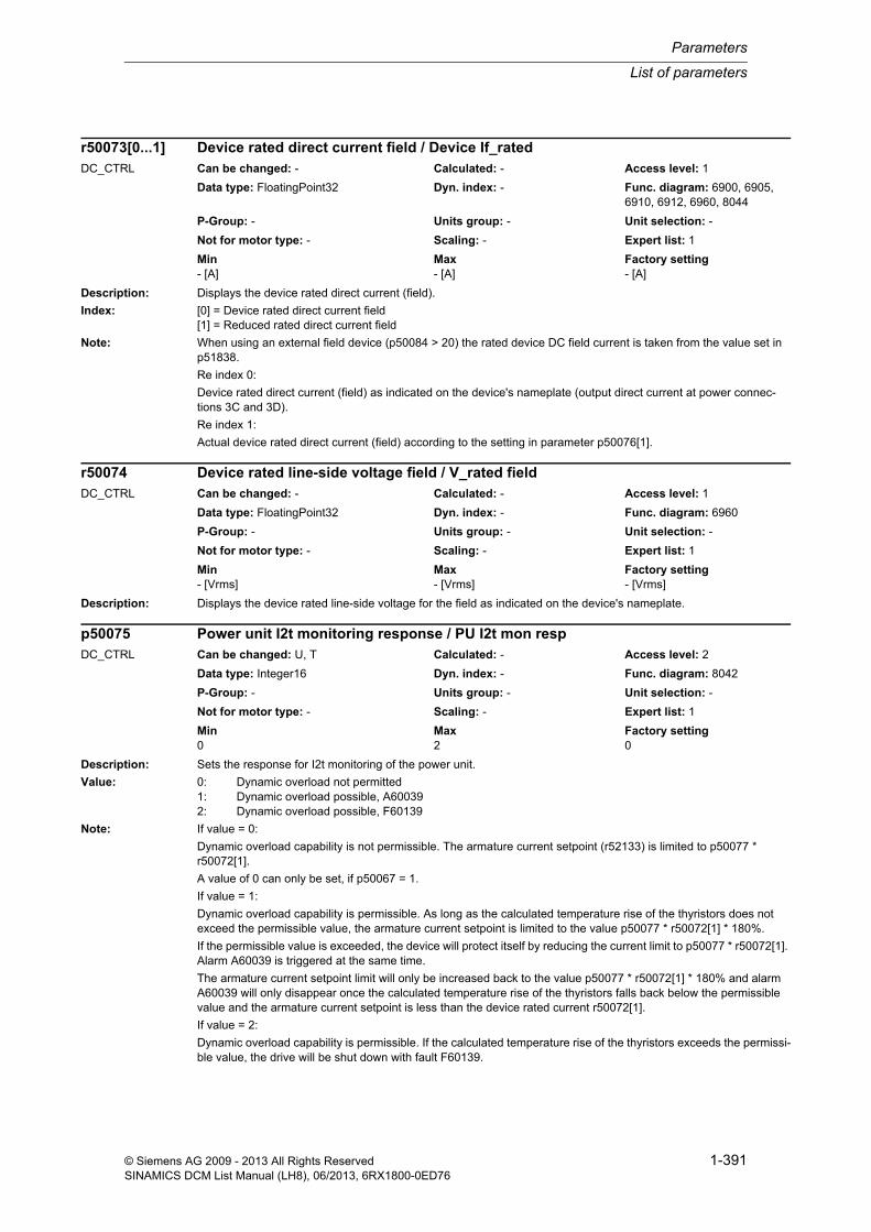
List of parameters
Parameters
1-391© Siemens AG 2009 - 2013 All Rights ReservedSINAMICS DCM List Manual (LH8), 06/2013, 6RX1800-0ED76
Description: Displays the device rated direct current (field).
Index: [0] = Device rated direct current field[1] = Reduced rated direct current field
Note: When using an external field device (p50084 > 20) the rated device DC field current is taken from the value set in p51838.
Re index 0:
Device rated direct current (field) as indicated on the device's nameplate (output direct current at power connec-tions 3C and 3D).
Re index 1:
Actual device rated direct current (field) according to the setting in parameter p50076[1].
Description: Displays the device rated line-side voltage for the field as indicated on the device's nameplate.
Description: Sets the response for I2t monitoring of the power unit.
Value: 0: Dynamic overload not permitted1: Dynamic overload possible, A600392: Dynamic overload possible, F60139
Note: If value = 0:
Dynamic overload capability is not permissible. The armature current setpoint (r52133) is limited to p50077 * r50072[1].
A value of 0 can only be set, if p50067 = 1.
If value = 1:
Dynamic overload capability is permissible. As long as the calculated temperature rise of the thyristors does not exceed the permissible value, the armature current setpoint is limited to the value p50077 * r50072[1] * 180%.
If the permissible value is exceeded, the device will protect itself by reducing the current limit to p50077 * r50072[1]. Alarm A60039 is triggered at the same time.
The armature current setpoint limit will only be increased back to the value p50077 * r50072[1] * 180% and alarm A60039 will only disappear once the calculated temperature rise of the thyristors falls back below the permissible value and the armature current setpoint is less than the device rated current r50072[1].
If value = 2:
Dynamic overload capability is permissible. If the calculated temperature rise of the thyristors exceeds the permissi-ble value, the drive will be shut down with fault F60139.
r50073[0...1] Device rated direct current field / Device If_ratedDC_CTRL Can be changed: - Calculated: - Access level: 1
Data type: FloatingPoint32 Dyn. index: - Func. diagram: 6900, 6905, 6910, 6912, 6960, 8044
P-Group: - Units group: - Unit selection: -
Not for motor type: - Scaling: - Expert list: 1
Min Max Factory setting - [A] - [A] - [A]
r50074 Device rated line-side voltage field / V_rated fieldDC_CTRL Can be changed: - Calculated: - Access level: 1
Data type: FloatingPoint32 Dyn. index: - Func. diagram: 6960
P-Group: - Units group: - Unit selection: -
Not for motor type: - Scaling: - Expert list: 1
Min Max Factory setting - [Vrms] - [Vrms] - [Vrms]
p50075 Power unit I2t monitoring response / PU I2t mon respDC_CTRL Can be changed: U, T Calculated: - Access level: 2
Data type: Integer16 Dyn. index: - Func. diagram: 8042
P-Group: - Units group: - Unit selection: -
Not for motor type: - Scaling: - Expert list: 1
Min Max Factory setting 0 2 0

Parameters
List of parameters
1-392 © Siemens AG 2009 - 2013 All Rights ReservedSINAMICS DCM List Manual (LH8), 06/2013, 6RX1800-0ED76
Description: Sets the reduction of the device rated direct current for armature and field.
The device rated direct current is reduced to the value set here to better adapt the device to the motor.
Index: [0] = Armature[1] = Field
Note: - If a load class has been set in parameter p50067 which reduces the device rated direct current, the smaller of the two values will be applied.
- The value set in index 0 (armature) results in a hardware-based adaption of the current actual value sensing gain. This can only be adapted in a discrete stages. As a consequence, the value set here is not precisely effective, but the next possible value. The actually effective rated device current can be seen in parameter r50072[1].
The following applies:
r50072[1] = K * r50072[0]
K = A/255
A = p50076[0] * 255/100 (rounded to the next lower integer number)
Description: Sets the derating factor for I2t monitoring of the power unit.
Note: Derating is required in the following cases:
- Operation at increased ambient temperature
- Installation altitude more than 1000 m above sea level
The derating factor should be taken from the following reference:
SINAMICS DCM Operating Instructions - Chapter "Derating" and "Sensor for ambient or air intake temperature"
Description: Sets the rated value of the supply voltage for armature and field.
This parameter should be used to set the rated voltage value of the actual line used to supply power to the power unit.
Index: [0] = Armature[1] = Field
Note: This value is the reference value for the following parameters:
p50351, p50352 , p50353
r52285 to r52289, r52291, r52292, r52301, r52302, r52303, r52305
Re index 0:
Only values less than r50071 can be set.
p50076[0...1] Device rated direct current reduction / Device I_rated redDC_CTRL Can be changed: C2(1), T Calculated: - Access level: 1
Data type: FloatingPoint32 Dyn. index: - Func. diagram: 6850, 6960
P-Group: - Units group: - Unit selection: -
Not for motor type: - Scaling: PERCENT Expert list: 1
Min Max Factory setting 1.0 [%] 100.0 [%] 100.0 [%]
p50077 Power unit I2t monitoring derating factor / PU I2t mon deratDC_CTRL Can be changed: T Calculated: - Access level: 2
Data type: FloatingPoint32 Dyn. index: - Func. diagram: 6840, 8042
P-Group: - Units group: - Unit selection: -
Not for motor type: - Scaling: - Expert list: 1
Min Max Factory setting 0.50 1.00 1.00
p50078[0...1] Supply voltage rated value / V_supp rated valDC_CTRL Can be changed: C2(1), T Calculated: - Access level: 1
Data type: FloatingPoint32 Dyn. index: - Func. diagram: 6855, 6900, 6902, 6950, 6952, 6960
P-Group: - Units group: - Unit selection: -
Not for motor type: - Scaling: - Expert list: 1
Min Max Factory setting 10 [Vrms] 2000 [Vrms] 400 [Vrms]

List of parameters
Parameters
1-393© Siemens AG 2009 - 2013 All Rights ReservedSINAMICS DCM List Manual (LH8), 06/2013, 6RX1800-0ED76
Re index 1:
Only values less than r50074 can be set.
Description: Sets the short pulses/long pulses on the armature gating unit.
Value = 0:
The gating unit emits short pulses (0.89 ms = approx. 16 degrees at 50 Hz).
Value = 1:
The gating unit emits long pulses (pulse duration up to approx. 0.1 ms before the next pulse) (e.g. required in the case of field infeed from the armature terminals).
Value: 0: Short pulses1: Long pulses
Description: Sets the braking mode for brake control.
Value: 0: No brake1: Holding brake2: Operational brake
Dependency: Refer to: p50370, p50371
Note: If p50080 = 1 (holding brake):
If the "Enable operation" command is withdrawn or the "Disconnect voltage" or "E-stop" command is set, the "Close brake" command will not be set until "n < n_min" is reached.
If p50080 = 2 (operational brake):
If the "Enable operation" command is withdrawn or the "Disconnect voltage" or "E-stop" command is set, the "Close brake" command will be set immediately (in other words, even if the motor is still running).
Description: Sets the activation/de-activation of EMF-dependent field weakening.
Value: 0: Deactivated1: Activated
Notice: When field weakening is active (p50081 = 1), a valid field characteristic must be available (p50117 = 1); if not, the optimization run for field weakening (p50051 = 27) must be performed.
p50079 Armature gating unit short pulses/long pulses / Arm sh/lg pulseDC_CTRL Can be changed: T Calculated: - Access level: 3
Data type: Integer16 Dyn. index: - Func. diagram: 6860
P-Group: - Units group: - Unit selection: -
Not for motor type: - Scaling: - Expert list: 1
Min Max Factory setting 0 1 0
p50080 Brake control braking mode / Brake ctr modeDC_CTRL Can be changed: T Calculated: - Access level: 2
Data type: Integer16 Dyn. index: - Func. diagram: 2750
P-Group: - Units group: - Unit selection: -
Not for motor type: - Scaling: - Expert list: 1
Min Max Factory setting 0 2 0
p50081 Field weakening activation / Field weak actDC_CTRL Can be changed: C2(1), T Calculated: - Access level: 1
Data type: Integer16 Dyn. index: - Func. diagram: 6900
P-Group: - Units group: - Unit selection: -
Not for motor type: - Scaling: - Expert list: 1
Min Max Factory setting 0 1 0
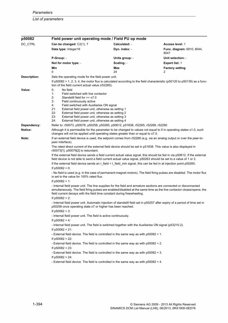
Parameters
List of parameters
1-394 © Siemens AG 2009 - 2013 All Rights ReservedSINAMICS DCM List Manual (LH8), 06/2013, 6RX1800-0ED76
Description: Sets the operating mode for the field power unit.
If p50082 = 1, 2, 3, 4, the motor flux is calculated according to the field characteristic (p50120 to p50139) as a func-tion of the field current actual value (r52265).
Value: 0: No field1: Field switched with line contactor2: Standstill field for >= o7.03: Field continuously active4: Field switched with Auxiliaries ON signal21: External field power unit, otherwise as setting 122: External field power unit, otherwise as setting 223: External field power unit, otherwise as setting 324: External field power unit, otherwise as setting 4
Dependency: Refer to: r50073, p50076, p50258, p50265, p50612, p51838, r52265, r52268, r52290
Notice: Although it is permissible for the parameter to be changed to values not equal to 0 in operating states o1.0, such changes will not be applied until operating states greater than or equal to o7.0.
Note: If an external field device is used, the setpoint comes from r52268 (e.g. via an analog output or over the peer-to-peer interface).
The rated direct current of the external field device should be set in p51838. This value is also displayed in r50073[1]. p50076[2] is redundant.
If the external field device sends a field current actual value signal, this should be fed in via p50612. If the external field device is not able to send a field current actual value signal, p50263 should be set to a value of 1 or 2.
If the external field device sends an I_field < I_field_min signal, this can be fed in at injection point p50265.
If p50082 = 0:
- No field is used (e.g. in the case of permanent-magnet motors). The field firing pulses are disabled. The motor flux is set to the value for 100% rated flux.
If p50082 = 1:
- Internal field power unit. The line supplies for the field and armature sections are connected or disconnected simultaneously. The field firing pulses are enabled/disabled at the same time as the line contactor closes/opens; the field current decays with the field time constant during freewheeling.
If p50082 = 2:
- Internal field power unit. Automatic injection of standstill field set in p50257 after expiry of a period of time set in p50258 once operating state o7 or higher has been reached.
If p50082 = 3:
- Internal field power unit. The field is active continuously.
If p50082 = 4:
- Internal field power unit. The field is switched together with the Auxiliaries ON signal (p53210.2).
If p50082 = 21:
- External field device. The field is controlled in the same way as with p50082 = 1.
If p50082 = 22:
- External field device. The field is controlled in the same way as with p50082 = 2.
If p50082 = 23:
- External field device. The field is controlled in the same way as with p50082 = 3.
If p50082 = 24:
- External field device. The field is controlled in the same way as with p50082 = 4.
p50082 Field power unit operating mode / Field PU op modeDC_CTRL Can be changed: C2(1), T Calculated: - Access level: 1
Data type: Integer16 Dyn. index: - Func. diagram: 6910, 8044, 8047
P-Group: - Units group: - Unit selection: -
Not for motor type: - Scaling: - Expert list: 1
Min Max Factory setting 0 24 2

List of parameters
Parameters
1-395© Siemens AG 2009 - 2013 All Rights ReservedSINAMICS DCM List Manual (LH8), 06/2013, 6RX1800-0ED76
Description: Selection of the speed actual value.
Value: 0: Selection de-activated1: Analog tachometer2: Incr encoder3: EMF actual value internal4: Free interconnection using p506095: DRIVE-CLiQ encoder
Dependency: Refer to: p50115, p50609
Warning: If value = 3:
Monitoring for overspeed is only active subject to restrictions since if the EMF is used as the speed actual value with a field current actual value which is too low, very high motor speeds will be reached.
Note: If value = 3:
The EMF actual value is evaluated with p50115.
Description: Sets closed-loop speed control or closed-loop current/torque control.
Value: 1: Closed-loop speed control2: Closed-loop current/torque control
Note: If value = 2:
The setpoint provided by the RFG output is set as the current/torque setpoint and the speed controller is bypassed.
Description: Sets the wait time for sequence control once the jog command has been withdrawn.
Once the jog command has been withdrawn, the wait time does not start until n < n_min (p50370, p50371) is reached.
Note: Once a jog command has been withdrawn, the drive will remain in operating state o1.3 for the set wait time, with the controllers inhibited and the line contactor picked up.
If a second jog command is sent during this time, the drive will switch to the next operating state (o1.2 or lower). However, if the time elapses without a second jog command being sent, the line contactor will drop out and the drive will switch to operating state o7.
p50083[0...n] Speed controller actual value selection / n_ctr act selDC_CTRL Can be changed: C2(1), T Calculated: - Access level: 1
Data type: Integer16 Dyn. index: DDS, p0180 Func. diagram: 6810
P-Group: - Units group: - Unit selection: -
Not for motor type: - Scaling: - Expert list: 1
Min Max Factory setting 0 5 0
p50084 Closed-loop speed control/Closed-loop current/torque control sel / n/I/tqe ctr selDC_CTRL Can be changed: T Calculated: - Access level: 2
Data type: Integer16 Dyn. index: - Func. diagram: 6810, 6830
P-Group: - Units group: - Unit selection: -
Not for motor type: - Scaling: - Expert list: 1
Min Max Factory setting 1 2 1
p50085 Sequence control withdraw jog wait time / S ctr jog tDC_CTRL Can be changed: U, T Calculated: - Access level: 2
Data type: FloatingPoint32 Dyn. index: - Func. diagram: 2651
P-Group: - Units group: - Unit selection: -
Not for motor type: - Scaling: - Expert list: 1
Min Max Factory setting 0.0 [s] 60.0 [s] 10.0 [s]

Parameters
List of parameters
1-396 © Siemens AG 2009 - 2013 All Rights ReservedSINAMICS DCM List Manual (LH8), 06/2013, 6RX1800-0ED76
Description: Sets the permissible duration of a line voltage failure.
If a line voltage failure lasts longer than this time, the corresponding fault will be triggered.
If the line voltage failure is shorter than the set time, a restart will follow automatically.
Caution: The value in p50090 must be smaller than that in p50086 (unless for a value = 0.0) and in p50089!
Description: Sets the brake closing time.
When "Open brake" is sent, the firing pulse enable is delayed by this time.
Note: For a negative time setting:
With "Open brake", a delay corresponding to the set time is applied in relation to the enable for the firing pulses for the thyristors. During this time, the motor works in opposition to the brake, which is still closed. This is useful, for example, in the cases of suspended loads.
For a positive time setting:
When the "Switch on", "Jog" or "Creep" command is sent with operation enabled, the firing pulses for the thyristors are not enabled until the set time has elapsed. During this time, the drive is in operating state o1.0 to give a holding brake the opportunity to open in advance.
Description: Sets the brake closing time.
When "Close brake" is sent, the firing pulse inhibit is delayed by this time.
Note: During this time, the drive is in operating state o1.1, o1.2, or o1.0 and is still applying torque.
Description: Sets the wait time for voltage and field current at the power unit.
p50086 Sequence control line voltage failure duration permissible / V_line_fail t permDC_CTRL Can be changed: U, T Calculated: - Access level: 2
Data type: FloatingPoint32 Dyn. index: - Func. diagram: 2651
P-Group: - Units group: - Unit selection: -
Not for motor type: - Scaling: - Expert list: 1
Min Max Factory setting 0.00 [s] 10.00 [s] 0.00 [s]
p50087 Brake control brake opening time / Br ctr t openDC_CTRL Can be changed: U, T Calculated: - Access level: 2
Data type: FloatingPoint32 Dyn. index: - Func. diagram: 2750
P-Group: - Units group: - Unit selection: -
Not for motor type: - Scaling: - Expert list: 1
Min Max Factory setting -10.00 [s] 10.00 [s] 0.00 [s]
p50088 Brake control brake closing time / Br ctr t closeDC_CTRL Can be changed: U, T Calculated: - Access level: 2
Data type: FloatingPoint32 Dyn. index: - Func. diagram: 2750
P-Group: - Units group: - Unit selection: -
Not for motor type: - Scaling: - Expert list: 1
Min Max Factory setting 0.00 [s] 10.00 [s] 0.00 [s]
p50089 Sequence control voltage at power unit wait time / S ctr V at PU tDC_CTRL Can be changed: U, T Calculated: - Access level: 2
Data type: FloatingPoint32 Dyn. index: - Func. diagram: 2651
P-Group: - Units group: - Unit selection: -
Not for motor type: - Scaling: - Expert list: 1
Min Max Factory setting 0.01 [s] 60.00 [s] 2.00 [s]

List of parameters
Parameters
1-397© Siemens AG 2009 - 2013 All Rights ReservedSINAMICS DCM List Manual (LH8), 06/2013, 6RX1800-0ED76
Once the line contactor has dropped out and the "Switch on", "Jog" or "Creep" commands have been sent, in oper-ating states o4 and o5, the drive waits for voltage at the power unit and for a field current actual value (r52265) > 50% of the field current setpoint (r52268).
If, during this time, no voltage is detected at the power unit and the field current is missing, a message is output accordingly.
Dependency: Refer to: p50353
Caution: The value in p50090 must be smaller than that in p50086 (unless p50086 = 0.0) and p50089!
Note: This parameter indicates the total wait times during which the drive must pass through operating states o4 and o5 (response threshold for monitoring for the presence of voltage at the power unit, see p50353).
Description: Sets the line voltage stabilization time.
Caution: The value in p50090 must be smaller than that in p50086 (unless p50086 = 0.0) and p50089!
Note: When the "Switch on", "Jog" or "Creep" command is sent and also after a phase failure affecting the line infeed has been detected with the "Automatic restart" function parameterized (p50086 > 0), the drive waits in operating state o4 for voltage at the power unit.
If amplitude, frequency and phase symmetry remain within the permissible tolerance for longer than this set stabili-zation time, line voltage is assumed to be present at the power connections.
Description: Sets the thresholds for "Switch on only with low setpoint" and "Automatic pulse inhibit with low setpoint".
Index: [0] = Switch on only with low setpoint[1] = Automatic pulse inhibit with low setpoint
Dependency: Refer to: r52166, r52193
Note: If p50091[0]:
Switching on is possible only if a setpoint |r52193| < p50091[0] is present at the RFG input.
If a higher setpoint is present, following activation, state o6 will remain set until |r52193| < p50091[0].
If p50091[1]:
If |r52193| and r52166 are smaller than p50091[1], the firing pulses will be inhibited and the motor will switch to state o2.0.
p50090 Line voltage stabilization time / V_line t_stabilDC_CTRL Can be changed: U, T Calculated: - Access level: 3
Data type: FloatingPoint32 Dyn. index: - Func. diagram: 6950, 6952
P-Group: - Units group: - Unit selection: -
Not for motor type: - Scaling: - Expert list: 1
Min Max Factory setting 0.01 [s] 1.00 [s] 0.05 [s]
p50091[0...1] Sequence control setpoint threshold / S ctr set threshDC_CTRL Can be changed: U, T Calculated: - Access level: 2
Data type: FloatingPoint32 Dyn. index: - Func. diagram: 2650, 2651
P-Group: - Units group: - Unit selection: -
Not for motor type: - Scaling: PERCENT Expert list: 1
Min Max Factory setting 0.00 [%] 200.00 [%] [0] 200.00 [%]
[1] 0.00 [%]

Parameters
List of parameters
1-398 © Siemens AG 2009 - 2013 All Rights ReservedSINAMICS DCM List Manual (LH8), 06/2013, 6RX1800-0ED76
Description: Sets the times to control the reversing contactor to reverse the field for a 2-quadrant device with field reversal.
Index: [0] = Field decay[1] = Control new field contactor[2] = Enable field firing pulses[3] = After field build up before armature enable
Dependency: Refer to: p50580, p50581, p50583, r53195
Note: Re index 0:
Wait time for the field to decay before opening the actual field contactor.
When initiating an operation to reverse the field, after reaching I_Field (r52265) < I_Field_min (p50394), this wait time expires before the actual field contactor is opened.
Re index 1:
Wait time before controlling the new field contactor.
After the actual field contactor has opened, this wait time expires before the field contactor is controlled for the "new" field direction (the dropout delay time of the contactor used is generally higher than the closing delay time).
Re index 2:
Wait time before enabling the field firing pulses.
After controlling the field contactor for the "new" field direction, this wait time expires before the field firing pulses are enabled. This time must be greater than the closing delay time of the contactor being used.
Re index 3:
Wait time after the field has been re-established before the armature is enabled.
After the field firing pulses have been enabled, the field current actual value I_field in the "new" field direction reaches the value I_field (r52265) > I_field_set (r52268) * p50398/100%. This wait time then starts to run. After this expires, the internal (armature) "operating enable for field reversal" is issued, and the drive is no longer held in operating state o1.4.
After the field current has been re-established, this wait time allows the system to wait for the overshoot of the field current actual value to end and therefore the overshoot of the EMF of the DC motor before armature operation is enabled. This is intended to avoid armature overcurrents due to an excessively high EMF during an overshoot.
Description: Sets the ON delay for the line contactor.
The switching on of the line contactor in relation to that of the auxiliaries is delayed by the time set here.
p50092[0...3] Field reversal wait times / Field rev t_waitDC_CTRL Can be changed: U, T Calculated: - Access level: 2
Data type: FloatingPoint32 Dyn. index: - Func. diagram: 6920
P-Group: - Units group: - Unit selection: -
Not for motor type: - Scaling: - Expert list: 1
Min Max Factory setting 0.0 [s] 10.0 [s] [0] 3.0 [s]
[1] 0.2 [s]
[2] 0.1 [s]
[3] 3.0 [s]
p50093 Sequence control line contactor ON delay / Line cont t_ONDC_CTRL Can be changed: U, T Calculated: - Access level: 2
Data type: FloatingPoint32 Dyn. index: - Func. diagram: 2651
P-Group: - Units group: - Unit selection: -
Not for motor type: - Scaling: - Expert list: 1
Min Max Factory setting 0.0 [s] 120.0 [s] 0.0 [s]

List of parameters
Parameters
1-399© Siemens AG 2009 - 2013 All Rights ReservedSINAMICS DCM List Manual (LH8), 06/2013, 6RX1800-0ED76
Description: Sets the OFF delay for the auxiliaries.
The switching off of the auxiliaries in relation to that of the line contactor is delayed by the time set here.
Description: Sets the wait time for a contactor in the DC circuit.
The time set in p50095 starts to elapse during a switch-on operation when operating state o5 is reached.
If this time is still running when operating state o4 is exited, then the system stays in state o3.2 until this time lapses.
Dependency: Refer to: p50691
Notice: If the motor is connected to the DC current output (terminal 1C1, 1D1) via a contactor, then generally, this contactor is also controlled from the relay for the line contactor (terminals 109, 110). In this case, it must be ensured that the firing pulses are only enabled after it is completely certain that the contactor has closed. To realize this, this addi-tional wait time is required when switching on.
Note: If the function "Feedback line contactor" is used, a change to 1 signal must be detected via p50691 within the time set in p50095. Otherwise, state o3.3 is adopted until it elapses and afterwards fault F60104 is triggered with fault value 6.
Description: Sets the run-on time for the device fan(s).
After a pulse inhibit (reaching an operating state >= 0.9), the device fan(s) run-on until the power unit has cooled down and until the run-time has expired.
The power unit is considered to have been cooled down if all of the following conditions apply:
- All temperature sensors of the power unit indicate values less than 35 °C.
- The thermal model for the thyristors supplies a value of less than 5 %.
- The field current is less than 10 A.
Dependency: Refer to: r53135
p50094 Sequence control auxiliaries OFF delay / Aux t_OFFDC_CTRL Can be changed: U, T Calculated: - Access level: 2
Data type: FloatingPoint32 Dyn. index: - Func. diagram: 2651
P-Group: - Units group: - Unit selection: -
Not for motor type: - Scaling: - Expert list: 1
Min Max Factory setting 0.0 [s] 6500.0 [s] 0.0 [s]
p50095 Sequence control DC circuit contactor wait time / DC cont t_waitDC_CTRL Can be changed: U, T Calculated: - Access level: 2
Data type: FloatingPoint32 Dyn. index: - Func. diagram: 2651
P-Group: - Units group: - Unit selection: -
Not for motor type: - Scaling: - Expert list: 1
Min Max Factory setting 0.00 [s] 1.00 [s] 0.00 [s]
p50096 Device fan run-on time / Dev fan t_run-onDC_CTRL Can be changed: U, T Calculated: - Access level: 2
Data type: FloatingPoint32 Dyn. index: - Func. diagram: 8047
P-Group: - Units group: - Unit selection: -
Not for motor type: - Scaling: - Expert list: 1
Min Max Factory setting 0.0 [s] 3600.0 [s] 240.0 [s]
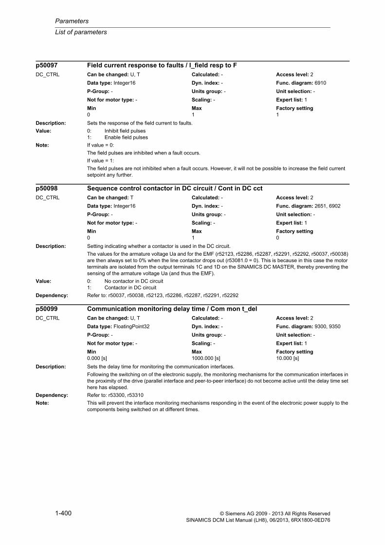
Parameters
List of parameters
1-400 © Siemens AG 2009 - 2013 All Rights ReservedSINAMICS DCM List Manual (LH8), 06/2013, 6RX1800-0ED76
Description: Sets the response of the field current to faults.
Value: 0: Inhibit field pulses1: Enable field pulses
Note: If value = 0:
The field pulses are inhibited when a fault occurs.
If value = 1:
The field pulses are not inhibited when a fault occurs. However, it will not be possible to increase the field current setpoint any further.
Description: Setting indicating whether a contactor is used in the DC circuit.
The values for the armature voltage Ua and for the EMF (r52123, r52286, r52287, r52291, r52292, r50037, r50038) are then always set to 0% when the line contactor drops out (r53081.0 = 0). This is because in this case the motor terminals are isolated from the output terminals 1C and 1D on the SINAMICS DC MASTER, thereby preventing the sensing of the armature voltage Ua (and thus the EMF).
Value: 0: No contactor in DC circuit1: Contactor in DC circuit
Dependency: Refer to: r50037, r50038, r52123, r52286, r52287, r52291, r52292
Description: Sets the delay time for monitoring the communication interfaces.
Following the switching on of the electronic supply, the monitoring mechanisms for the communication interfaces in the proximity of the drive (parallel interface and peer-to-peer interface) do not become active until the delay time set here has elapsed.
Dependency: Refer to: r53300, r53310
Note: This will prevent the interface monitoring mechanisms responding in the event of the electronic power supply to the components being switched on at different times.
p50097 Field current response to faults / I_field resp to FDC_CTRL Can be changed: U, T Calculated: - Access level: 2
Data type: Integer16 Dyn. index: - Func. diagram: 6910
P-Group: - Units group: - Unit selection: -
Not for motor type: - Scaling: - Expert list: 1
Min Max Factory setting 0 1 1
p50098 Sequence control contactor in DC circuit / Cont in DC cctDC_CTRL Can be changed: T Calculated: - Access level: 2
Data type: Integer16 Dyn. index: - Func. diagram: 2651, 6902
P-Group: - Units group: - Unit selection: -
Not for motor type: - Scaling: - Expert list: 1
Min Max Factory setting 0 1 0
p50099 Communication monitoring delay time / Com mon t_delDC_CTRL Can be changed: U, T Calculated: - Access level: 2
Data type: FloatingPoint32 Dyn. index: - Func. diagram: 9300, 9350
P-Group: - Units group: - Unit selection: -
Not for motor type: - Scaling: - Expert list: 1
Min Max Factory setting 0.000 [s] 1000.000 [s] 10.000 [s]

List of parameters
Parameters
1-401© Siemens AG 2009 - 2013 All Rights ReservedSINAMICS DCM List Manual (LH8), 06/2013, 6RX1800-0ED76
Description: Sets the rated armature current as indicated on the motor's nameplate.
Note: If p50100 = 0.0 A, the drive cannot be switched on and put into operation.
Description: Sets the rated armature voltage as indicated on the motor's nameplate.
This parameter is used, for example, to specify the trigger point in field weakening operation.
Note: If a significant voltage drop is to be expected at the motor's supply line when the motor is at rated current (e.g. very long motor cable), a value increased by this voltage drop should be set at p50101.
Description: Sets the rated excitation current as indicated on the motor's nameplate.
Note: If p50102 = 0.00 A, the drive cannot be switched on and put into operation.
Description: Sets the minimum excitation current for the motor.
Description: Sets speed n1 according to the motor's nameplate for "speed-dependent current limitation".
The characteristic for "speed-dependent current limitation" is defined by 2 pairs of values (p50104/p50105, p50106/p50107).
This parameter sets speed n1 for the first pair of values (p50104/p50105).
p50100[0...n] Motor rated armature current / Mot rated I_armatDC_CTRL Can be changed: C2(1), T Calculated: - Access level: 1
Data type: FloatingPoint32 Dyn. index: DDS, p0180 Func. diagram: 6851, 8038
P-Group: - Units group: - Unit selection: -
Not for motor type: - Scaling: - Expert list: 1
Min Max Factory setting 0.0 [A] 20000.0 [A] 0.0 [A]
p50101[0...n] Motor rated armature voltage / Mot rated V_armatDC_CTRL Can be changed: C2(1), T Calculated: - Access level: 1
Data type: FloatingPoint32 Dyn. index: DDS, p0180 Func. diagram: 6900
P-Group: - Units group: - Unit selection: -
Not for motor type: - Scaling: - Expert list: 1
Min Max Factory setting 10 [V] 2800 [V] 400 [V]
p50102[0...n] Motor rated excitation current / Mot rated I_excDC_CTRL Can be changed: C2(1), U, T Calculated: - Access level: 1
Data type: FloatingPoint32 Dyn. index: DDS, p0180 Func. diagram: 6905
P-Group: - Units group: - Unit selection: -
Not for motor type: - Scaling: - Expert list: 1
Min Max Factory setting 0.00 [A] 600.00 [A] 0.00 [A]
p50103[0...n] Minimum motor excitation current / Mot I_exc minDC_CTRL Can be changed: U, T Calculated: - Access level: 2
Data type: FloatingPoint32 Dyn. index: DDS, p0180 Func. diagram: 6905
P-Group: - Units group: - Unit selection: -
Not for motor type: - Scaling: - Expert list: 1
Min Max Factory setting 0.00 [A] 100.00 [A] 0.00 [A]
p50104[0...n] Speed-dependent current limitation speed n1 / I_lim n_dep n1DC_CTRL Can be changed: C2(1), U, T Calculated: - Access level: 1
Data type: FloatingPoint32 Dyn. index: DDS, p0180 Func. diagram: 8040
P-Group: - Units group: - Unit selection: -
Not for motor type: - Scaling: - Expert list: 1
Min Max Factory setting 1 [rpm] 10000 [rpm] 5000 [rpm]

Parameters
List of parameters
1-402 © Siemens AG 2009 - 2013 All Rights ReservedSINAMICS DCM List Manual (LH8), 06/2013, 6RX1800-0ED76
Dependency: Refer to: p50105, p50106, p50107, p50108, p50109
Note: The following condition applies:
p50104 <= p50106 (n1 <= n2)
Description: Sets armature current I1 according to the motor's nameplate for "speed-dependent current limitation".
The characteristic for "speed-dependent current limitation" is defined by 2 pairs of values (p50104/p50105, p50106/p50107).
This parameter sets armature current I1 for the first pair of values (p50104/p50105).
Dependency: Refer to: p50104, p50106, p50107, p50108, p50109
Note: The following condition applies:
p50105 >= p50107 (I1 >= I2)
Description: Sets speed n2 according to the motor's nameplate for "speed-dependent current limitation".
The characteristic for "speed-dependent current limitation" is defined by 2 pairs of values (p50104/p50105, p50106/p50107).
This parameter sets speed n2 for the second pair of values (p50106/p50107).
Dependency: Refer to: p50104, p50105, p50107, p50108, p50109
Note: The following condition applies:
p50104 <= p50106 (n1 <= n2)
Description: Sets armature current I2 according to the motor's nameplate for "speed-dependent current limitation".
The characteristic for "speed-dependent current limitation" is defined by 2 pairs of values (p50104/p50105, p50106/p50107).
This parameter sets armature current I2 for the second pair of values (p50106/p50107).
Dependency: Refer to: p50104, p50105, p50106, p50108, p50109
Note: The following condition applies:
p50105 >= p50107 (I1 >= I2)
p50105[0...n] Speed-dependent current limitation armature current I1 / I_lim n_dep I1DC_CTRL Can be changed: C2(1), U, T Calculated: - Access level: 1
Data type: FloatingPoint32 Dyn. index: DDS, p0180 Func. diagram: 8040
P-Group: - Units group: - Unit selection: -
Not for motor type: - Scaling: - Expert list: 1
Min Max Factory setting 0.1 [A] 20000.0 [A] 0.1 [A]
p50106[0...n] Speed-dependent current limitation speed n2 / I_lim n_dep n2DC_CTRL Can be changed: C2(1), U, T Calculated: - Access level: 1
Data type: FloatingPoint32 Dyn. index: DDS, p0180 Func. diagram: 8040
P-Group: - Units group: - Unit selection: -
Not for motor type: - Scaling: - Expert list: 1
Min Max Factory setting 1 [rpm] 10000 [rpm] 5000 [rpm]
p50107[0...n] Speed-dependent current limitation armature current I2 / I_lim n_dep I2DC_CTRL Can be changed: C2(1), U, T Calculated: - Access level: 1
Data type: FloatingPoint32 Dyn. index: DDS, p0180 Func. diagram: 8040
P-Group: - Units group: - Unit selection: -
Not for motor type: - Scaling: - Expert list: 1
Min Max Factory setting 0.1 [A] 20000.0 [A] 0.1 [A]

List of parameters
Parameters
1-403© Siemens AG 2009 - 2013 All Rights ReservedSINAMICS DCM List Manual (LH8), 06/2013, 6RX1800-0ED76
Description: Sets the maximum operating speed n3 for "speed-dependent current limitation".
Dependency: Refer to: p50104, p50105, p50106, p50107, p50109
Note: In this parameter, the following maximum speed must be set dependent upon the setting of the signal source for the speed actual value (p50083):
- p50083 = 1 (analog tachometer): Speed prevailing at a tachometer voltage according to p50741
- p50083 = 2 (incremental encoder TTL/HTL): Same value as maximum speed according to p50143
- p50083 = 3 (operation without tachometer): Speed prevailing at an EMF according to p50115.
Description: Sets activation/de-activation of the "speed-dependent current limitation" function.
Value: 0: Deactivated1: Activated
Description: Sets the armature circuit resistance.
Note: The parameter is set automatically during the optimization run for pre-control and the current controller for the armature converter (p50051 = 25).
Description: Sets the armature circuit inductance.
Note: The parameter is set automatically during the optimization run for pre-control and the current controller for the armature converter (p50051 = 25).
p50108[0...n] Speed-dependent current limitation maximum operating speed n3 / I_lim n_dep n3DC_CTRL Can be changed: C2(1), U, T Calculated: - Access level: 1
Data type: FloatingPoint32 Dyn. index: DDS, p0180 Func. diagram: 8040
P-Group: - Units group: - Unit selection: -
Not for motor type: - Scaling: - Expert list: 1
Min Max Factory setting 1 [rpm] 10000 [rpm] 5000 [rpm]
p50109[0...n] Speed-dependent current limitation activation / I_lim n_dep actDC_CTRL Can be changed: C2(1), U, T Calculated: - Access level: 1
Data type: Integer16 Dyn. index: DDS, p0180 Func. diagram: 8040
P-Group: - Units group: - Unit selection: -
Not for motor type: - Scaling: - Expert list: 1
Min Max Factory setting 0 1 0
p50110[0...n] Armature circuit resistance / RaDC_CTRL Can be changed: U, T Calculated: - Access level: 3
Data type: FloatingPoint32 Dyn. index: DDS, p0180 Func. diagram: 6852, 6855, 6900, 6902
P-Group: - Units group: - Unit selection: -
Not for motor type: - Scaling: - Expert list: 1
Min Max Factory setting 0.000 [ohm] 4000.000 [ohm] 0.000 [ohm]
p50111[0...n] Armature circuit inductance / LaDC_CTRL Can be changed: U, T Calculated: - Access level: 3
Data type: FloatingPoint32 Dyn. index: DDS, p0180 Func. diagram: 6852, 6854, 6902
P-Group: - Units group: - Unit selection: -
Not for motor type: - Scaling: - Expert list: 1
Min Max Factory setting 0.000 [mH] 1000000.000 [mH] 0.000 [mH]

Parameters
List of parameters
1-404 © Siemens AG 2009 - 2013 All Rights ReservedSINAMICS DCM List Manual (LH8), 06/2013, 6RX1800-0ED76
Description: Sets the field circuit resistance.
Note: The parameter is set automatically during the optimization run for closed-loop field current control (p50051 = 24).
Description: Sets the permissible continuous armature current for motor I2t monitoring.
Note: At this permissible continuous current, fault F60037 is not output.
The current is calculated as follows: p50113 * p50100.
Description: Sets the thermal time constant of the motor.
Note: Value = 0:
The motor's I2t monitoring is de-activated.
Description: Setting of the percentage value in relation to p50078[0] for specifying the EMF at maximum speed.
The speed is adjusted using the EMF as the speed actual value.
Description: Sets the field circuit inductance.
Dependency: Refer to: p51597
p50112[0...n] Field circuit resistance / R_field circuitDC_CTRL Can be changed: U, T Calculated: - Access level: 3
Data type: FloatingPoint32 Dyn. index: DDS, p0180 Func. diagram: 6910
P-Group: - Units group: - Unit selection: -
Not for motor type: - Scaling: - Expert list: 1
Min Max Factory setting 0.000 [ohm] 4000.000 [ohm] 0.000 [ohm]
p50113[0...n] Motor I2t monitoring continuous current factor / Mot I2t I_contDC_CTRL Can be changed: U, T Calculated: - Access level: 2
Data type: FloatingPoint32 Dyn. index: DDS, p0180 Func. diagram: 8038
P-Group: - Units group: - Unit selection: -
Not for motor type: - Scaling: - Expert list: 1
Min Max Factory setting 0.50 2.00 1.00
p50114[0...n] Motor thermal time constant / Mot T thermDC_CTRL Can be changed: C2(1), U, T Calculated: - Access level: 1
Data type: FloatingPoint32 Dyn. index: DDS, p0180 Func. diagram: 8038
P-Group: - Units group: - Unit selection: -
Not for motor type: - Scaling: - Expert list: 1
Min Max Factory setting 0 [s] 10000 [s] 600 [s]
p50115[0...n] Speed controller EMF at maximum speed / EMF at n_maxDC_CTRL Can be changed: C2(1), U, T Calculated: - Access level: 1
Data type: FloatingPoint32 Dyn. index: DDS, p0180 Func. diagram: 6810
P-Group: - Units group: - Unit selection: -
Not for motor type: - Scaling: PERCENT Expert list: 1
Min Max Factory setting 1.00 [%] 140.00 [%] 100.00 [%]
p50116[0...n] Field circuit inductance / L_field circuitDC_CTRL Can be changed: U, T Calculated: - Access level: 3
Data type: FloatingPoint32 Dyn. index: DDS, p0180 Func. diagram: 6910
P-Group: - Units group: - Unit selection: -
Not for motor type: - Scaling: - Expert list: 1
Min Max Factory setting 0.0 [mH] 1000000.0 [mH] 0.0 [mH]
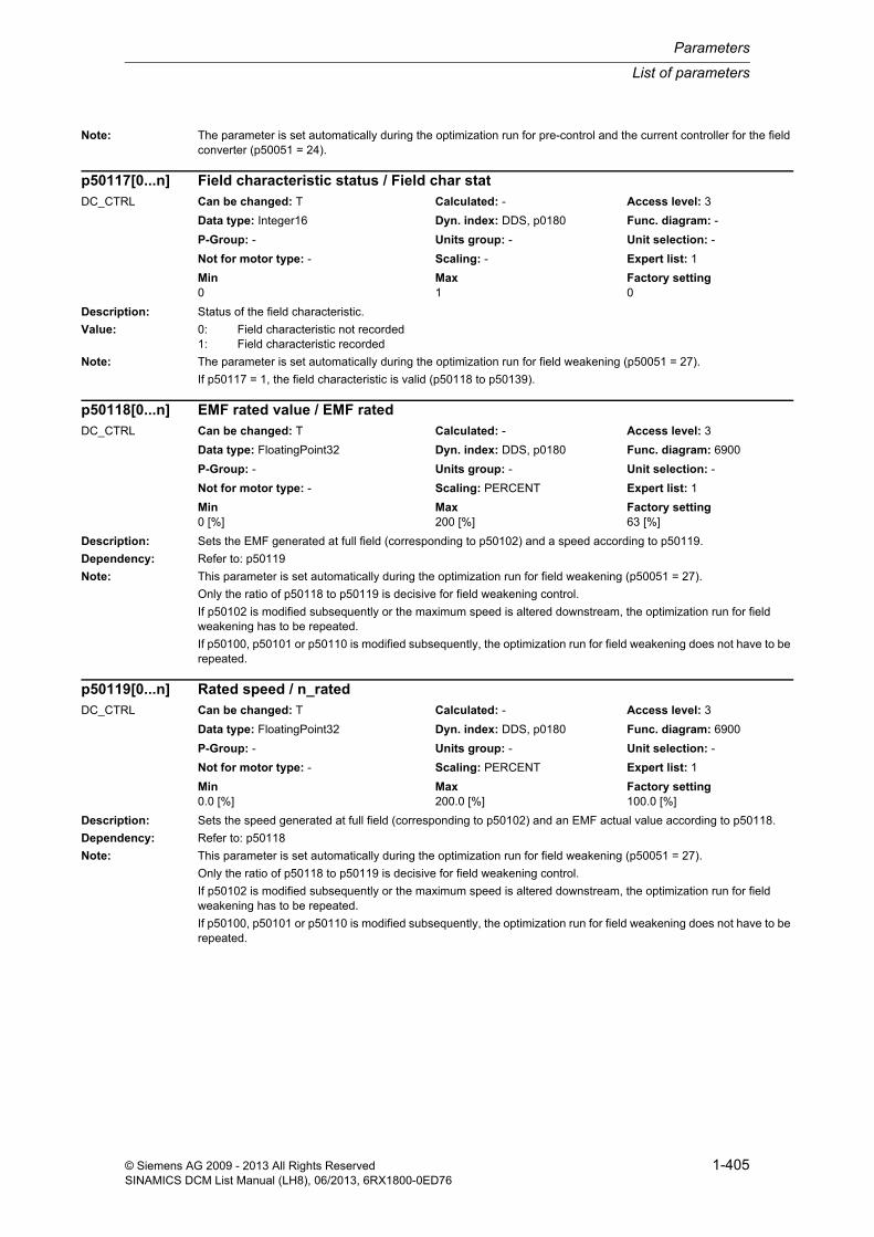
List of parameters
Parameters
1-405© Siemens AG 2009 - 2013 All Rights ReservedSINAMICS DCM List Manual (LH8), 06/2013, 6RX1800-0ED76
Note: The parameter is set automatically during the optimization run for pre-control and the current controller for the field converter (p50051 = 24).
Description: Status of the field characteristic.
Value: 0: Field characteristic not recorded1: Field characteristic recorded
Note: The parameter is set automatically during the optimization run for field weakening (p50051 = 27).
If p50117 = 1, the field characteristic is valid (p50118 to p50139).
Description: Sets the EMF generated at full field (corresponding to p50102) and a speed according to p50119.
Dependency: Refer to: p50119
Note: This parameter is set automatically during the optimization run for field weakening (p50051 = 27).
Only the ratio of p50118 to p50119 is decisive for field weakening control.
If p50102 is modified subsequently or the maximum speed is altered downstream, the optimization run for field weakening has to be repeated.
If p50100, p50101 or p50110 is modified subsequently, the optimization run for field weakening does not have to be repeated.
Description: Sets the speed generated at full field (corresponding to p50102) and an EMF actual value according to p50118.
Dependency: Refer to: p50118
Note: This parameter is set automatically during the optimization run for field weakening (p50051 = 27).
Only the ratio of p50118 to p50119 is decisive for field weakening control.
If p50102 is modified subsequently or the maximum speed is altered downstream, the optimization run for field weakening has to be repeated.
If p50100, p50101 or p50110 is modified subsequently, the optimization run for field weakening does not have to be repeated.
p50117[0...n] Field characteristic status / Field char statDC_CTRL Can be changed: T Calculated: - Access level: 3
Data type: Integer16 Dyn. index: DDS, p0180 Func. diagram: -
P-Group: - Units group: - Unit selection: -
Not for motor type: - Scaling: - Expert list: 1
Min Max Factory setting 0 1 0
p50118[0...n] EMF rated value / EMF ratedDC_CTRL Can be changed: T Calculated: - Access level: 3
Data type: FloatingPoint32 Dyn. index: DDS, p0180 Func. diagram: 6900
P-Group: - Units group: - Unit selection: -
Not for motor type: - Scaling: PERCENT Expert list: 1
Min Max Factory setting 0 [%] 200 [%] 63 [%]
p50119[0...n] Rated speed / n_ratedDC_CTRL Can be changed: T Calculated: - Access level: 3
Data type: FloatingPoint32 Dyn. index: DDS, p0180 Func. diagram: 6900
P-Group: - Units group: - Unit selection: -
Not for motor type: - Scaling: PERCENT Expert list: 1
Min Max Factory setting 0.0 [%] 200.0 [%] 100.0 [%]

Parameters
List of parameters
1-406 © Siemens AG 2009 - 2013 All Rights ReservedSINAMICS DCM List Manual (LH8), 06/2013, 6RX1800-0ED76
Description: Setting of the field current for a motor flux of 0 %.
Note: This parameter is set automatically during the optimization run for field weakening (p50051 = 27).
Only values less than p50121 can be set.
Description: Setting of the field current for a motor flux of 5 %.
Note: This parameter is set automatically during the optimization run for field weakening (p50051 = 27).
Only values greater than p50120 and less than p50122 can be set.
Description: Setting of the field current for a motor flux of 10 %.
Note: This parameter is set automatically during the optimization run for field weakening (p50051 = 27).
Only values greater than p50121 and less than p50123 can be set.
Description: Setting of the field current for a motor flux of 15 %.
Note: This parameter is set automatically during the optimization run for field weakening (p50051 = 27).
Only values greater than p50122 and less than p50124 can be set.
p50120[0...n] Field current for motor flux 0 % / I_field flux 0%DC_CTRL Can be changed: T Calculated: - Access level: 3
Data type: FloatingPoint32 Dyn. index: DDS, p0180 Func. diagram: 6900, 6910
P-Group: - Units group: - Unit selection: -
Not for motor type: - Scaling: PERCENT Expert list: 1
Min Max Factory setting 0.0 [%] 100.0 [%] 0.0 [%]
p50121[0...n] Field current for motor flux 5 % / I_field flux 5%DC_CTRL Can be changed: T Calculated: - Access level: 3
Data type: FloatingPoint32 Dyn. index: DDS, p0180 Func. diagram: 6900, 6910
P-Group: - Units group: - Unit selection: -
Not for motor type: - Scaling: PERCENT Expert list: 1
Min Max Factory setting 0.0 [%] 100.0 [%] 3.7 [%]
p50122[0...n] Field current for motor flux 10 % / I_field flux 10%DC_CTRL Can be changed: T Calculated: - Access level: 3
Data type: FloatingPoint32 Dyn. index: DDS, p0180 Func. diagram: 6900, 6910
P-Group: - Units group: - Unit selection: -
Not for motor type: - Scaling: PERCENT Expert list: 1
Min Max Factory setting 0.0 [%] 100.0 [%] 7.3 [%]
p50123[0...n] Field current for motor flux 15 % / I_field flux 15%DC_CTRL Can be changed: T Calculated: - Access level: 3
Data type: FloatingPoint32 Dyn. index: DDS, p0180 Func. diagram: 6900, 6910
P-Group: - Units group: - Unit selection: -
Not for motor type: - Scaling: PERCENT Expert list: 1
Min Max Factory setting 0.0 [%] 100.0 [%] 11.0 [%]
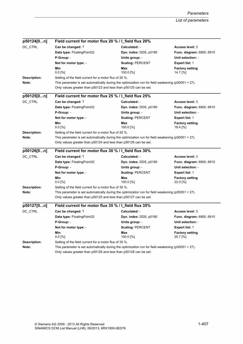
List of parameters
Parameters
1-407© Siemens AG 2009 - 2013 All Rights ReservedSINAMICS DCM List Manual (LH8), 06/2013, 6RX1800-0ED76
Description: Setting of the field current for a motor flux of 20 %.
Note: This parameter is set automatically during the optimization run for field weakening (p50051 = 27).
Only values greater than p50123 and less than p50125 can be set.
Description: Setting of the field current for a motor flux of 25 %.
Note: This parameter is set automatically during the optimization run for field weakening (p50051 = 27).
Only values greater than p50124 and less than p50126 can be set.
Description: Setting of the field current for a motor flux of 30 %.
Note: This parameter is set automatically during the optimization run for field weakening (p50051 = 27).
Only values greater than p50125 and less than p50127 can be set.
Description: Setting of the field current for a motor flux of 35 %.
Note: This parameter is set automatically during the optimization run for field weakening (p50051 = 27).
Only values greater than p50126 and less than p50128 can be set.
p50124[0...n] Field current for motor flux 20 % / I_field flux 20%DC_CTRL Can be changed: T Calculated: - Access level: 3
Data type: FloatingPoint32 Dyn. index: DDS, p0180 Func. diagram: 6900, 6910
P-Group: - Units group: - Unit selection: -
Not for motor type: - Scaling: PERCENT Expert list: 1
Min Max Factory setting 0.0 [%] 100.0 [%] 14.7 [%]
p50125[0...n] Field current for motor flux 25 % / I_field flux 25%DC_CTRL Can be changed: T Calculated: - Access level: 3
Data type: FloatingPoint32 Dyn. index: DDS, p0180 Func. diagram: 6900, 6910
P-Group: - Units group: - Unit selection: -
Not for motor type: - Scaling: PERCENT Expert list: 1
Min Max Factory setting 0.0 [%] 100.0 [%] 18.4 [%]
p50126[0...n] Field current for motor flux 30 % / I_field flux 30%DC_CTRL Can be changed: T Calculated: - Access level: 3
Data type: FloatingPoint32 Dyn. index: DDS, p0180 Func. diagram: 6900, 6910
P-Group: - Units group: - Unit selection: -
Not for motor type: - Scaling: PERCENT Expert list: 1
Min Max Factory setting 0.0 [%] 100.0 [%] 22.0 [%]
p50127[0...n] Field current for motor flux 35 % / I_field flux 35%DC_CTRL Can be changed: T Calculated: - Access level: 3
Data type: FloatingPoint32 Dyn. index: DDS, p0180 Func. diagram: 6900, 6910
P-Group: - Units group: - Unit selection: -
Not for motor type: - Scaling: PERCENT Expert list: 1
Min Max Factory setting 0.0 [%] 100.0 [%] 25.7 [%]

Parameters
List of parameters
1-408 © Siemens AG 2009 - 2013 All Rights ReservedSINAMICS DCM List Manual (LH8), 06/2013, 6RX1800-0ED76
Description: Setting of the field current for a motor flux of 40 %.
Note: This parameter is set automatically during the optimization run for field weakening (p50051 = 27).
Only values greater than p50127 and less than p50129 can be set.
Description: Setting of the field current for a motor flux of 45 %.
Note: This parameter is set automatically during the optimization run for field weakening (p50051 = 27).
Only values greater than p50128 and less than p50130 can be set.
Description: Setting of the field current for a motor flux of 50 %.
Note: This parameter is set automatically during the optimization run for field weakening (p50051 = 27).
Only values greater than p50129 and less than p50131 can be set.
Description: Setting of the field current for a motor flux of 55 %.
Note: This parameter is set automatically during the optimization run for field weakening (p50051 = 27).
Only values greater than p50130 and less than p50132 can be set.
p50128[0...n] Field current for motor flux 40 % / I_field flux 40%DC_CTRL Can be changed: T Calculated: - Access level: 3
Data type: FloatingPoint32 Dyn. index: DDS, p0180 Func. diagram: 6900, 6910
P-Group: - Units group: - Unit selection: -
Not for motor type: - Scaling: PERCENT Expert list: 1
Min Max Factory setting 0.0 [%] 100.0 [%] 29.4 [%]
p50129[0...n] Field current for motor flux 45 % / I_field flux 45%DC_CTRL Can be changed: T Calculated: - Access level: 3
Data type: FloatingPoint32 Dyn. index: DDS, p0180 Func. diagram: 6900, 6910
P-Group: - Units group: - Unit selection: -
Not for motor type: - Scaling: PERCENT Expert list: 1
Min Max Factory setting 0.0 [%] 100.0 [%] 33.1 [%]
p50130[0...n] Field current for motor flux 50 % / I_field flux 50%DC_CTRL Can be changed: T Calculated: - Access level: 3
Data type: FloatingPoint32 Dyn. index: DDS, p0180 Func. diagram: 6900, 6910
P-Group: - Units group: - Unit selection: -
Not for motor type: - Scaling: PERCENT Expert list: 1
Min Max Factory setting 0.0 [%] 100.0 [%] 36.8 [%]
p50131[0...n] Field current for motor flux 55 % / I_field flux 55%DC_CTRL Can be changed: T Calculated: - Access level: 3
Data type: FloatingPoint32 Dyn. index: DDS, p0180 Func. diagram: 6900, 6910
P-Group: - Units group: - Unit selection: -
Not for motor type: - Scaling: PERCENT Expert list: 1
Min Max Factory setting 0.0 [%] 100.0 [%] 40.6 [%]

List of parameters
Parameters
1-409© Siemens AG 2009 - 2013 All Rights ReservedSINAMICS DCM List Manual (LH8), 06/2013, 6RX1800-0ED76
Description: Setting of the field current for a motor flux of 60 %.
Note: This parameter is set automatically during the optimization run for field weakening (p50051 = 27).
Only values greater than p50131 and less than p50133 can be set.
Description: Setting of the field current for a motor flux of 65 %.
Note: This parameter is set automatically during the optimization run for field weakening (p50051 = 27).
Only values greater than p50132 and less than p50134 can be set.
Description: Setting of the field current for a motor flux of 70 %.
Note: This parameter is set automatically during the optimization run for field weakening (p50051 = 27).
Only values greater than p50133 and less than p50135 can be set.
Description: Setting of the field current for a motor flux of 75 %.
Note: This parameter is set automatically during the optimization run for field weakening (p50051 = 27).
Only values greater than p50134 and less than p50136 can be set.
p50132[0...n] Field current for motor flux 60 % / I_field flux 60%DC_CTRL Can be changed: T Calculated: - Access level: 3
Data type: FloatingPoint32 Dyn. index: DDS, p0180 Func. diagram: 6900, 6910
P-Group: - Units group: - Unit selection: -
Not for motor type: - Scaling: PERCENT Expert list: 1
Min Max Factory setting 0.0 [%] 100.0 [%] 44.6 [%]
p50133[0...n] Field current for motor flux 65 % / I_field flux 65%DC_CTRL Can be changed: T Calculated: - Access level: 3
Data type: FloatingPoint32 Dyn. index: DDS, p0180 Func. diagram: 6900, 6910
P-Group: - Units group: - Unit selection: -
Not for motor type: - Scaling: PERCENT Expert list: 1
Min Max Factory setting 0.0 [%] 100.0 [%] 48.9 [%]
p50134[0...n] Field current for motor flux 70 % / I_field flux 70%DC_CTRL Can be changed: T Calculated: - Access level: 3
Data type: FloatingPoint32 Dyn. index: DDS, p0180 Func. diagram: 6900, 6910
P-Group: - Units group: - Unit selection: -
Not for motor type: - Scaling: PERCENT Expert list: 1
Min Max Factory setting 0.0 [%] 100.0 [%] 53.6 [%]
p50135[0...n] Field current for motor flux 75 % / I_field flux 75%DC_CTRL Can be changed: T Calculated: - Access level: 3
Data type: FloatingPoint32 Dyn. index: DDS, p0180 Func. diagram: 6900, 6910
P-Group: - Units group: - Unit selection: -
Not for motor type: - Scaling: PERCENT Expert list: 1
Min Max Factory setting 0.0 [%] 100.0 [%] 58.9 [%]

Parameters
List of parameters
1-410 © Siemens AG 2009 - 2013 All Rights ReservedSINAMICS DCM List Manual (LH8), 06/2013, 6RX1800-0ED76
Description: Setting of the field current for a motor flux of 80 %.
Note: This parameter is set automatically during the optimization run for field weakening (p50051 = 27).
Only values greater than p50135 and less than p50137 can be set.
Description: Setting of the field current for a motor flux of 85 %.
Note: This parameter is set automatically during the optimization run for field weakening (p50051 = 27).
Only values greater than p50136 and less than p50138 can be set.
Description: Setting of the field current for a motor flux of 90 %.
Note: This parameter is set automatically during the optimization run for field weakening (p50051 = 27).
Only values greater than p50137 and less than p50139 can be set.
Description: Setting of the field current for a motor flux of 95%.
Note: This parameter is set automatically during the optimization run for field weakening (p50051 = 27).
Only values greater than p50138 can be set.
p50136[0...n] Field current for motor flux 80 % / I_field flux 80%DC_CTRL Can be changed: T Calculated: - Access level: 3
Data type: FloatingPoint32 Dyn. index: DDS, p0180 Func. diagram: 6900, 6910
P-Group: - Units group: - Unit selection: -
Not for motor type: - Scaling: PERCENT Expert list: 1
Min Max Factory setting 0.0 [%] 100.0 [%] 64.9 [%]
p50137[0...n] Field current for motor flux 85 % / I_field flux 85%DC_CTRL Can be changed: T Calculated: - Access level: 3
Data type: FloatingPoint32 Dyn. index: DDS, p0180 Func. diagram: 6900, 6910
P-Group: - Units group: - Unit selection: -
Not for motor type: - Scaling: PERCENT Expert list: 1
Min Max Factory setting 0.0 [%] 100.0 [%] 71.8 [%]
p50138[0...n] Field current for motor flux 90 % / I_field flux 90%DC_CTRL Can be changed: T Calculated: - Access level: 3
Data type: FloatingPoint32 Dyn. index: DDS, p0180 Func. diagram: 6900, 6910
P-Group: - Units group: - Unit selection: -
Not for motor type: - Scaling: PERCENT Expert list: 1
Min Max Factory setting 0.0 [%] 100.0 [%] 79.8 [%]
p50139[0...n] Field current for motor flux 95% / I_field flux 95%DC_CTRL Can be changed: T Calculated: - Access level: 3
Data type: FloatingPoint32 Dyn. index: DDS, p0180 Func. diagram: 6900, 6910
P-Group: - Units group: - Unit selection: -
Not for motor type: - Scaling: PERCENT Expert list: 1
Min Max Factory setting 0.0 [%] 100.0 [%] 89.1 [%]

List of parameters
Parameters
1-411© Siemens AG 2009 - 2013 All Rights ReservedSINAMICS DCM List Manual (LH8), 06/2013, 6RX1800-0ED76
Description: Sets the starting behavior for I2t monitoring of the motor.
Value: 2: Start I2t with zero12: Start I2t with saved value
Note: If value = 12:
For motor I2t monitoring, when switching off, the model temperature is saved in a non-volatile fashion. When switching on, the saved value is taken into account in the model calculation. As a consequence, the UL508C speci-fication is fulfilled.
Description: Sets the inverter stability limit for the firing angle of the armature converter in single-phase operation.
Dependency: Refer to: r53190
Note: The status of the Alpha W limit is shown in r53190.8.
Description: Setting of the correction angle for current-dependent offset of the Alpha W limit.
Description: Sets the rectifier stability limit for the firing angle of the armature converter.
Dependency: Refer to: r53190
Note: The status of the Alpha G limit is shown in r53190.7.
p50140 Motor I2t monitoring starting behavior / Mot I2t strt behavDC_CTRL Can be changed: U, T Calculated: - Access level: 2
Data type: Integer16 Dyn. index: - Func. diagram: 8038
P-Group: - Units group: - Unit selection: -
Not for motor type: - Scaling: - Expert list: 1
Min Max Factory setting 2 12 12
p50148[0...n] Armature converter Alpha W limit (single-phase operation) / A Alpha W lim 1-phDC_CTRL Can be changed: U, T Calculated: - Access level: 3
Data type: FloatingPoint32 Dyn. index: DDS, p0180 Func. diagram: 6860
P-Group: - Units group: - Unit selection: -
Not for motor type: - Scaling: - Expert list: 1
Min Max Factory setting 120.0 [°] 180.0 [°] 178.0 [°]
p50149[0...n] Armature converter correction angle Alpha W limit / Arm corr Alpha WDC_CTRL Can be changed: U, T Calculated: - Access level: 3
Data type: FloatingPoint32 Dyn. index: DDS, p0180 Func. diagram: 6860
P-Group: - Units group: - Unit selection: -
Not for motor type: - Scaling: - Expert list: 1
Min Max Factory setting -60.0 [°] 0.0 [°] 0.0 [°]
p50150[0...n] Armature converter Alpha G limit / Arm Alpha G limDC_CTRL Can be changed: U, T Calculated: - Access level: 3
Data type: FloatingPoint32 Dyn. index: DDS, p0180 Func. diagram: 6860
P-Group: - Units group: - Unit selection: -
Not for motor type: - Scaling: - Expert list: 1
Min Max Factory setting 0.0 [°] 165.0 [°] 30.0 [°]

Parameters
List of parameters
1-412 © Siemens AG 2009 - 2013 All Rights ReservedSINAMICS DCM List Manual (LH8), 06/2013, 6RX1800-0ED76
Description: Sets the inverter stability limit for the firing angle of the armature converter.
Dependency: Refer to: r53190
Note: The status of the Alpha W limit is shown in r53190.8.
Description: Setting of the number of line periods for line frequency correction in the armature circuit.
Note: The internal line synchronization for the armature firing pulses derived from the power terminals (line infeed) is averaged over the number of line periods set in this parameter.
In the case of operation on "weak" power supplies with unstable frequencies (on a diesel-driven generator, for example (isolated operation), this parameter must be set lower than for operation on "constant V/Hz" systems to achieve a higher frequency correction speed.
Description: Sets the control word for armature pre-control.
Value: 0: Armature pre-control disabled and pre-control = 165 °1: Armature pre-control active2: Armature pre-control active EMF only with torque direction chge3: Armature pre-control active EMF irrelevant
Note: If value = 3:
For pre-control, in this case the EMF is applied with a value of 0 (recommended setting in the case of supplying high inductances from armature terminals, e.g. solenoids, field supply).
Description: Sets activation/de-activation of the integral component on the armature current controller.
Value: 0: Deactivated1: Activated
p50151[0...n] Armature converter Alpha W limit / Arm Alpha W limDC_CTRL Can be changed: U, T Calculated: - Access level: 3
Data type: FloatingPoint32 Dyn. index: DDS, p0180 Func. diagram: 6860
P-Group: - Units group: - Unit selection: -
Not for motor type: - Scaling: - Expert list: 1
Min Max Factory setting 120.0 [°] 165.0 [°] 150.0 [°]
p50152[0...n] Armature average number of line periods / Arm line per no.DC_CTRL Can be changed: T Calculated: - Access level: 3
Data type: Unsigned16 Dyn. index: DDS, p0180 Func. diagram: 6950
P-Group: - Units group: - Unit selection: -
Not for motor type: - Scaling: - Expert list: 1
Min Max Factory setting 1 20 20
p50153[0...n] Control word for armature pre-control / A prec STWDC_CTRL Can be changed: T Calculated: - Access level: 2
Data type: Integer16 Dyn. index: DDS, p0180 Func. diagram: 6855
P-Group: - Units group: - Unit selection: -
Not for motor type: - Scaling: - Expert list: 1
Min Max Factory setting 0 3 1
p50154[0...n] Closed-loop armature current control integral comp activation / Ia ctr I comp actDC_CTRL Can be changed: T Calculated: - Access level: 2
Data type: Integer16 Dyn. index: DDS, p0180 Func. diagram: 6855
P-Group: - Units group: - Unit selection: -
Not for motor type: - Scaling: - Expert list: 1
Min Max Factory setting 0 1 1

List of parameters
Parameters
1-413© Siemens AG 2009 - 2013 All Rights ReservedSINAMICS DCM List Manual (LH8), 06/2013, 6RX1800-0ED76
Note: If value = 0:
The integral component of the armature current controller is kept constantly at zero (i.e. the armature current con-troller functions solely as a proportional controller).
Description: Sets the P gain of the armature current controller.
Dependency: Refer to: p50175
Note: The parameter is set automatically during the optimization run for pre-control and the current controller for the armature converter (p50051 = 25).
The P gain (Kp) for the armature current controller is calculated as follows:
Kp = p50155 x |p50175|
Description: Sets the integral time of the armature current controller.
Dependency: Refer to: p50176
Note: The parameter is set automatically during the optimization run for pre-control and the current controller for the armature converter (p50051 = 25).
The integral time (Tn) for the armature current controller is calculated as follows:
Tn = p50156 x |p50176|
Description: Selection of the current setpoint integrator.
Value: 0: Reduced gearbox stressing1: Current setpoint integrator
Note: If value = 0:
The integrator is only effective after a change in torque direction (only functions as a ramp-function generator for the current setpoint until the first time the output reaches the setpoint at the integrator input after a change in torque direction).
If value = 1:
The integrator is always effective (functions as a ramp-function generator for the current setpoint).
p50155[0...n] Closed-loop armature current control P gain / Ia ctr KpDC_CTRL Can be changed: U, T Calculated: - Access level: 2
Data type: FloatingPoint32 Dyn. index: DDS, p0180 Func. diagram: 6855
P-Group: - Units group: - Unit selection: -
Not for motor type: - Scaling: - Expert list: 1
Min Max Factory setting 0.01 200.00 0.10
p50156[0...n] Closed-loop armature current control integral time / Ia ctr TnDC_CTRL Can be changed: U, T Calculated: - Access level: 2
Data type: FloatingPoint32 Dyn. index: DDS, p0180 Func. diagram: 6855
P-Group: - Units group: - Unit selection: -
Not for motor type: - Scaling: - Expert list: 1
Min Max Factory setting 0.001 [s] 10.000 [s] 0.200 [s]
p50157[0...n] Current limitation setpoint integrator selection / I_set integ selDC_CTRL Can be changed: T Calculated: - Access level: 2
Data type: Integer16 Dyn. index: DDS, p0180 Func. diagram: 6845
P-Group: - Units group: - Unit selection: -
Not for motor type: - Scaling: - Expert list: 1
Min Max Factory setting 0 1 0

Parameters
List of parameters
1-414 © Siemens AG 2009 - 2013 All Rights ReservedSINAMICS DCM List Manual (LH8), 06/2013, 6RX1800-0ED76
Description: Sets the ramp-up time for the setpoint integrator during current limitation.
Duration of a ramp-up in the event of a setpoint jump from 0 to 100% of parameter r50072[1].
Notice: When setting a ramp-up time > 0.000 s, it is not permissible to enter a supplementary current setpoint via p50601[5]. p50601[5] must be set = 0.
Possible effect if this is not observed:
Torque direction change will not be able to be completed. The drive remains in one torque direction.
Description: Sets the changeover threshold for the torque direction in the auto-reversing stage.
Description: Sets the additional torque-free interval when switching over the torque direction in the auto-reversing stage.
Description: Sets the additional Alpha W pulses with inhibited second pulse in the auto-reversing stage.
Recommend.: This parameter should be set to values > 0 in particular when supplying high inductances (e.g. infeed of solenoids).
Dependency: Refer to: p50179
Note: Number of additional Alpha W pulses with disabled second pulse following detection of I = 0 signal prior to a change in torque direction.
These pulses cause the current to decay prior to a change in torque direction.
When it drops below the thyristor holding current value, the current is suddenly chopped by the unfired second thy-ristor and the residual energy stored in the load inductance must be dissipated via a protective circuit (e.g. a varis-tor) to prevent the load inductance from producing an overvoltage.
p50158[0...n] Current limitation setpoint integrator ramp-up time / Set integ t_r-upDC_CTRL Can be changed: U, T Calculated: - Access level: 2
Data type: FloatingPoint32 Dyn. index: DDS, p0180 Func. diagram: 6845
P-Group: - Units group: - Unit selection: -
Not for motor type: - Scaling: - Expert list: 1
Min Max Factory setting 0.000 [s] 1.000 [s] 0.000 [s]
p50159[0...n] Auto-reversing stage changeover threshold / Auto-rev threshDC_CTRL Can be changed: U, T Calculated: - Access level: 2
Data type: FloatingPoint32 Dyn. index: DDS, p0180 Func. diagram: 6860
P-Group: - Units group: - Unit selection: -
Not for motor type: - Scaling: PERCENT Expert list: 1
Min Max Factory setting 0.00 [%] 100.00 [%] 0.01 [%]
p50160[0...n] Auto-reversing stage additional torque-free interval / Auto-rev intervalDC_CTRL Can be changed: U, T Calculated: - Access level: 2
Data type: FloatingPoint32 Dyn. index: DDS, p0180 Func. diagram: 6860
P-Group: - Units group: - Unit selection: -
Not for motor type: - Scaling: - Expert list: 1
Min Max Factory setting 0.000 [s] 2.000 [s] 0.000 [s]
p50161[0...n] Auto-reversing stage Alpha W pulses second pulse inhibited / Auto-rev Alpha W1DC_CTRL Can be changed: U, T Calculated: - Access level: 2
Data type: Unsigned16 Dyn. index: DDS, p0180 Func. diagram: 6860
P-Group: - Units group: - Unit selection: -
Not for motor type: - Scaling: - Expert list: 1
Min Max Factory setting 0 50000 0

List of parameters
Parameters
1-415© Siemens AG 2009 - 2013 All Rights ReservedSINAMICS DCM List Manual (LH8), 06/2013, 6RX1800-0ED76
Description: Sets the calculation method for the EMF in armature pre-control.
Value: 1: Measured EMF2: EMF with Ua from p501933: EMF with EMF from p501934: EMF with EMF from r52167
Note: If p50162 = 1:
The EMF derived from the measured armature voltage (r52123) is used.
If p50162 = 2:
The EMF for armature current pre-control is calculated from the armature voltage selected with p50193 (the resis-tive + inductive armature voltage drop is subtracted internally; if p50079 = 2, then p50110 and p50111 only apply at half their value).
If p50162 = 3:
The parameter selected with p50193 is used as the EMF for armature current pre-control. This setting also allows a closed-loop DC link voltage control to be implemented.
If p50162 = 4:
The EMF for the armature precontrol (12-pulse in parallel) is calculated as follows:
r52290 * (r52167/p50119) * p50118
Description: Sets the method for filtering the EMF for armature pre-control.
Value: 0: No filtering1: Averaging over last 1 EMF values2: Averaging over last 2 EMF values3: Averaging over last 3 EMF values4: Averaging over last 4 EMF values5: Averaging over last 5 EMF values6: Averaging over last 6 EMF values10: PT1 time constant = 10 ms20: PT1 time constant = 20 ms40: PT1 time constant = 40 ms80: PT1 time constant = 80 ms160: PT1 time constant = 160 ms
Description: Sets activation/de-activation of the proportional component for armature current control.
p50162[0...n] EMF selection / EMF selDC_CTRL Can be changed: T Calculated: - Access level: 2
Data type: Integer16 Dyn. index: DDS, p0180 Func. diagram: 6852
P-Group: - Units group: - Unit selection: -
Not for motor type: - Scaling: - Expert list: 1
Min Max Factory setting 1 4 1
p50163[0...n] EMF smoothing selection / EMF smoothing selDC_CTRL Can be changed: T Calculated: - Access level: 2
Data type: Integer16 Dyn. index: DDS, p0180 Func. diagram: 6852
P-Group: - Units group: - Unit selection: -
Not for motor type: - Scaling: - Expert list: 1
Min Max Factory setting 0 160 6
p50164[0...n] Closed-loop armature current ctr proportional comp activation / Ia ctr Kp actDC_CTRL Can be changed: T Calculated: - Access level: 2
Data type: Integer16 Dyn. index: DDS, p0180 Func. diagram: 6855
P-Group: - Units group: - Unit selection: -
Not for motor type: - Scaling: - Expert list: 1
Min Max Factory setting 0 1 1

Parameters
List of parameters
1-416 © Siemens AG 2009 - 2013 All Rights ReservedSINAMICS DCM List Manual (LH8), 06/2013, 6RX1800-0ED76
Value: 0: Deactivated1: Activated
Note: If value = 0:
The proportional component of the armature current controller is kept constantly at zero (i.e. the armature current controller functions solely as an integral controller).
Description: Sets the signal source to enable a torque direction in the event of a change in torque direction.
1 signal:
Enable available for M0 or MI.
0 signal:
Enable available for M0 or MII.
Description: Setting to activate/de-activate the calculation of the thyristor blocking voltage.
Value: 0: De-activating1: Activating
Note: The calculation of the thyristor blocking voltage can only be activated if the hardware (Power Interface Module) sup-ports this function.
This parameter is only evaluated once while powering up, i.e. a change only becomes effective after POWER ON or after powering up with saved parameters (p0976 = 11).
Description: Setting to select torque limiting or current limitation.
Value: 0: Current lim1: Torque limiting
Dependency: If p50169 = 1 or p50170 = 1:
A valid field characteristic (p50117 = 1) is required, otherwise fault F60055 will be output on power-up. If this setting is selected, the optimization run for field weakening must be performed in advance (p50051 = 27).
Parameter p50263 defines the input variable for determining the motor flux.
If p50169 = 1 and p50170 = 1:
This is an invalid setting.
If p50170 = 1, it will not be possible to set p50169 = 1.
Refer to: p50051, p50117, p50263
p50165[0...n] BI: Signal source for change in torque direction enable / Torq dir en sig sDC_CTRL Can be changed: T Calculated: - Access level: 2
Data type: Unsigned32 / Binary Dyn. index: CDS, p0170 Func. diagram: 6860
P-Group: - Units group: - Unit selection: -
Not for motor type: - Scaling: - Expert list: 1
Min Max Factory setting - - 53190.0
p50166 Thyristor blocking voltage calculation activation / Thy_block_calc actDC_CTRL Can be changed: T Calculated: - Access level: 3
Data type: Integer16 Dyn. index: - Func. diagram: 6860
P-Group: - Units group: - Unit selection: -
Not for motor type: - Scaling: - Expert list: 1
Min Max Factory setting 0 1 0
p50169[0...n] Torque limiting selection torque limiting/current limitation / T lim sel T/I_limDC_CTRL Can be changed: T Calculated: - Access level: 2
Data type: Integer16 Dyn. index: DDS, p0180 Func. diagram: 6830
P-Group: - Units group: - Unit selection: -
Not for motor type: - Scaling: - Expert list: 1
Min Max Factory setting 0 1 1

List of parameters
Parameters
1-417© Siemens AG 2009 - 2013 All Rights ReservedSINAMICS DCM List Manual (LH8), 06/2013, 6RX1800-0ED76
Note: If p50169 = 0:
Current limitation.
If p50169 = 1:
Torque limiting; in other words, the pre-set torque limit is converted into a current limit:
current limit = torque limit/motor flux
Description: Sets the controller's control type (closed-loop current control or closed-loop torque control).
p50170 = 0:
The controller is current-controlled.
p50170 = 1:
The controller is torque-controlled; in other words, the torque setpoint is converted into a current setpoint (current setpoint = torque setpoint/motor flux).
Value: 0: Closed-loop current control1: Closed-loop torque control
Dependency: If p50169 or p50170 is set to a value of 1, there must be a valid field characteristic (p50117 = 1); otherwise fault F60055 will be output on power-up. If this setting is selected, the optimization run for field weakening must be per-formed in advance (p50051 = 27).
Parameter p50263 defines the input variable for determining the motor flux.
If p50169 = 1 and p50170 = 1:
This is an invalid setting. If p50169 = 1, it will not be possible to set p50170 = 1.
Refer to: p50051, p50117, p50173, p50263
Note: The following parameters are used to change over between current control and torque control:
- Signal source via connector input p50173
or
- Fixed set value in p50170
Description: Sets the factor for the armature current limit in torque direction I.
Description: Sets the factor for the armature current limit in torque direction II.
p50170[0...n] Selection of control type for closed-loop current/torque control / Ctrl type I/tq selDC_CTRL Can be changed: T Calculated: - Access level: 2
Data type: Integer16 Dyn. index: DDS, p0180 Func. diagram: 6835
P-Group: - Units group: - Unit selection: -
Not for motor type: - Scaling: - Expert list: 1
Min Max Factory setting 0 1 0
p50171[0...n] Current limitation armature current limit torque dir I factor / Ia lim t d I factDC_CTRL Can be changed: C2(1), U, T Calculated: - Access level: 1
Data type: FloatingPoint32 Dyn. index: DDS, p0180 Func. diagram: 6825, 6840
P-Group: - Units group: - Unit selection: -
Not for motor type: - Scaling: PERCENT Expert list: 1
Min Max Factory setting 0.0 [%] 300.0 [%] 100.0 [%]
p50172[0...n] Current limitation armature current limit torque dir II factor / Ia lim t d II factDC_CTRL Can be changed: C2(1), U, T Calculated: - Access level: 1
Data type: FloatingPoint32 Dyn. index: DDS, p0180 Func. diagram: 6825, 6840
P-Group: - Units group: - Unit selection: -
Not for motor type: - Scaling: PERCENT Expert list: 1
Min Max Factory setting -300.0 [%] 0.0 [%] -100.0 [%]

Parameters
List of parameters
1-418 © Siemens AG 2009 - 2013 All Rights ReservedSINAMICS DCM List Manual (LH8), 06/2013, 6RX1800-0ED76
Description: Sets the signal source for changeover between closed-loop current control and closed-loop torque control.
p50170 = 0 and p50173 = 0 signal:
The controller is current-controlled.
p50170 = 1 or p50173 = 1 signal:
The controller is torque-controlled; in other words, the torque setpoint is converted into a current setpoint (current setpoint = torque setpoint/motor flux).
Dependency: If p50169 or p50170 is set to a value of 1, there must be a valid field characteristic (p50117 = 1); otherwise fault F60055 will be output on power-up. If this setting is selected, the optimization run for field weakening must be per-formed in advance (p50051 = 27).
Parameter p50263 defines the input variable for determining the motor flux.
Refer to: p50170
Note: The following parameters are used to change over between current control and torque control:
- Signal source via connector input p50173
or
- Fixed set value in p50170
Description: Sets the signal source for variable control of the armature current controller's P gain.
Dependency: Refer to: p50155
Note: The P gain (Kp) for the armature current controller is calculated as follows:
Kp = p50155 x |p50175|
Description: Sets the signal source for variable control of the armature current controller's integral time.
Note: The integral time (Tn) for the armature current controller is calculated as follows:
Tn = p50156 x |p50176|
p50173[0...n] BI: Signal source for closed-loop current/torque control ctr type / Ctr I/tq ctr sig sDC_CTRL Can be changed: T Calculated: - Access level: 2
Data type: Unsigned32 / Binary Dyn. index: CDS, p0170 Func. diagram: 6835
P-Group: - Units group: - Unit selection: -
Not for motor type: - Scaling: - Expert list: 1
Min Max Factory setting - - 0
p50175[0...n] CI: Signal source for closed-loop armature current control P gain / Ia ctr Kp sig sDC_CTRL Can be changed: T Calculated: - Access level: 3
Data type: Unsigned32 / FloatingPoint32 Dyn. index: CDS, p0170 Func. diagram: 6855
P-Group: - Units group: - Unit selection: -
Not for motor type: - Scaling: PERCENT Expert list: 1
Min Max Factory setting - - 1
p50176[0...n] CI: Signal source for closed-loop armature current ctr integr time / Ia ctr Tn sig sDC_CTRL Can be changed: T Calculated: - Access level: 3
Data type: Unsigned32 / FloatingPoint32 Dyn. index: CDS, p0170 Func. diagram: 6855
P-Group: - Units group: - Unit selection: -
Not for motor type: - Scaling: PERCENT Expert list: 1
Min Max Factory setting - - 1

List of parameters
Parameters
1-419© Siemens AG 2009 - 2013 All Rights ReservedSINAMICS DCM List Manual (LH8), 06/2013, 6RX1800-0ED76
Description: Sets the signal source for the "No immediate pulse inhibit" command.
A low signal will cause the armature firing pulses to be inhibited immediately without waiting for the I = 0 signal or sending Alpha W pulses for current decay. The additional Alpha W pulses (as set in p50161 and p50179) are not output either. As long as this command is pending, it will not be possible to switch to an operating state lower than o1.6.
Note: This command can be used, for example, if the drive is being used to supply a field rather than a motor and the cur-rent is to be reduced via an external built-on field discharge resistor connected in parallel.
Description: Sets the signal source for the "Fire all thyristors simultaneously" command.
The default setting of this command (high signal) causes all 6 thyristors on thyristor bridge I to be fired continuously and simultaneously. Changeover to long pulses is automatic.
Note: However, this command is only active if no line voltage is applied to the armature power unit.
Description: Sets the additional Alpha W pulses with enabled second pulse in the auto-reversing stage.
Recommend.: This parameter should be set to values > 0 in particular when supplying high inductances (e.g. infeed of solenoids).
Note: Number of additional Alpha W pulses with enabled second pulse following detection of I = 0 signal prior to a change in torque direction.
These pulses cause the current to decay before a change in torque direction; the thyristors are fired in pairs to pre-vent sudden chopping and the generation of overvoltage by the load inductance when the current drops below the thyristor holding current.
When a change in torque direction is required, the current in the existing direction must be reduced.
Description: Sets positive torque limit 1.
Dependency: Refer to: p50182
p50177[0...n] BI: Signal source for the "No immediate pulse inhibit" command / No pulse inh sig sDC_CTRL Can be changed: T Calculated: - Access level: 2
Data type: Unsigned32 / Binary Dyn. index: CDS, p0170 Func. diagram: 6860
P-Group: - Units group: - Unit selection: -
Not for motor type: - Scaling: - Expert list: 1
Min Max Factory setting - - 1
p50178[0...n] BI: Sig source for the "Fire all thyristors simultaneously" command / All thy fire sig sDC_CTRL Can be changed: T Calculated: - Access level: 2
Data type: Unsigned32 / Binary Dyn. index: CDS, p0170 Func. diagram: 6860
P-Group: - Units group: - Unit selection: -
Not for motor type: - Scaling: - Expert list: 1
Min Max Factory setting - - 0
p50179[0...n] Auto-reversing stage Alpha W pluses second pulse enabled / Auto-rev Alpha W2DC_CTRL Can be changed: U, T Calculated: - Access level: 2
Data type: Unsigned16 Dyn. index: DDS, p0180 Func. diagram: 6860
P-Group: - Units group: - Unit selection: -
Not for motor type: - Scaling: - Expert list: 1
Min Max Factory setting 0 50000 0
p50180[0...n] Torque limiting torque limit 1 positive / T lim 1 posDC_CTRL Can be changed: C2(1), U, T Calculated: - Access level: 1
Data type: FloatingPoint32 Dyn. index: DDS, p0180 Func. diagram: 6825
P-Group: - Units group: - Unit selection: -
Not for motor type: - Scaling: PERCENT Expert list: 1
Min Max Factory setting -300.00 [%] 300.00 [%] 300.00 [%]

Parameters
List of parameters
1-420 © Siemens AG 2009 - 2013 All Rights ReservedSINAMICS DCM List Manual (LH8), 06/2013, 6RX1800-0ED76
Note: If torque limit changeover is selected (p50694 = 1) and the speed is higher than the set changeover speed (p50184), then torque limit 2 is activated in place of torque limit 1.
Description: Sets negative torque limit 1.
Dependency: Refer to: p50183
Note: If torque limit changeover is selected (p50694 = 1) and the speed is higher than the set changeover speed (p50184), then torque limit 2 is activated in place of torque limit 1.
Description: Sets positive torque limit 2.
Dependency: Refer to: p50180
Note: If torque limit changeover is selected (p50694 = 1) and the speed is higher than the set changeover speed (p50184), then torque limit 2 is activated in place of torque limit 1.
Description: Sets negative torque limit 2.
Dependency: Refer to: p50181
Note: If torque limit changeover is selected (p50694 = 1) and the speed is higher than the set changeover speed (p50184), then torque limit 2 is activated in place of torque limit 1.
Description: Sets the changeover speed for torque limit selection.
Dependency: Refer to: r52166
Note: If torque limit changeover is selected (p50694 = 1) and the speed (p52166) is higher than the changeover speed set in p50184, then torque limit 2 (p50182, p50183) is activated in place of torque limit 1 (p50180, p50181).
p50181[0...n] Torque limiting torque limit 1 negative / T lim 1 negDC_CTRL Can be changed: C2(1), U, T Calculated: - Access level: 1
Data type: FloatingPoint32 Dyn. index: DDS, p0180 Func. diagram: 6825
P-Group: - Units group: - Unit selection: -
Not for motor type: - Scaling: PERCENT Expert list: 1
Min Max Factory setting -300.00 [%] 300.00 [%] -300.00 [%]
p50182[0...n] Torque limiting torque limit 2 positive / T lim 2 posDC_CTRL Can be changed: U, T Calculated: - Access level: 2
Data type: FloatingPoint32 Dyn. index: DDS, p0180 Func. diagram: 6825
P-Group: - Units group: - Unit selection: -
Not for motor type: - Scaling: PERCENT Expert list: 1
Min Max Factory setting -300.00 [%] 300.00 [%] 300.00 [%]
p50183[0...n] Torque limiting torque limit 2 negative / T lim 2 negDC_CTRL Can be changed: U, T Calculated: - Access level: 2
Data type: FloatingPoint32 Dyn. index: DDS, p0180 Func. diagram: 6825
P-Group: - Units group: - Unit selection: -
Not for motor type: - Scaling: PERCENT Expert list: 1
Min Max Factory setting -300.00 [%] 300.00 [%] -300.00 [%]
p50184[0...n] Torque limiting changeover speed / T lim n_chngDC_CTRL Can be changed: U, T Calculated: - Access level: 2
Data type: FloatingPoint32 Dyn. index: DDS, p0180 Func. diagram: 6825
P-Group: - Units group: - Unit selection: -
Not for motor type: - Scaling: PERCENT Expert list: 1
Min Max Factory setting 0.00 [%] 120.00 [%] 0.00 [%]
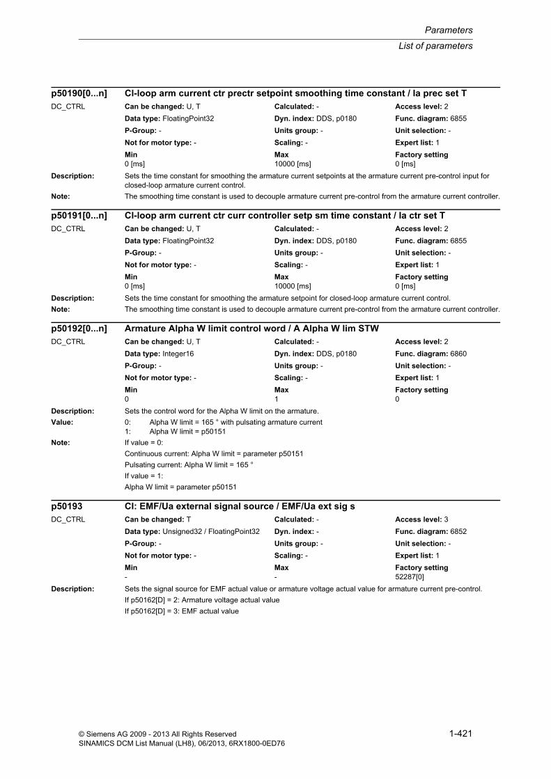
List of parameters
Parameters
1-421© Siemens AG 2009 - 2013 All Rights ReservedSINAMICS DCM List Manual (LH8), 06/2013, 6RX1800-0ED76
Description: Sets the time constant for smoothing the armature current setpoints at the armature current pre-control input for closed-loop armature current control.
Note: The smoothing time constant is used to decouple armature current pre-control from the armature current controller.
Description: Sets the time constant for smoothing the armature setpoint for closed-loop armature current control.
Note: The smoothing time constant is used to decouple armature current pre-control from the armature current controller.
Description: Sets the control word for the Alpha W limit on the armature.
Value: 0: Alpha W limit = 165 ° with pulsating armature current1: Alpha W limit = p50151
Note: If value = 0:
Continuous current: Alpha W limit = parameter p50151
Pulsating current: Alpha W limit = 165 °
If value = 1:
Alpha W limit = parameter p50151
Description: Sets the signal source for EMF actual value or armature voltage actual value for armature current pre-control.
If p50162[D] = 2: Armature voltage actual value
If p50162[D] = 3: EMF actual value
p50190[0...n] Cl-loop arm current ctr prectr setpoint smoothing time constant / Ia prec set TDC_CTRL Can be changed: U, T Calculated: - Access level: 2
Data type: FloatingPoint32 Dyn. index: DDS, p0180 Func. diagram: 6855
P-Group: - Units group: - Unit selection: -
Not for motor type: - Scaling: - Expert list: 1
Min Max Factory setting 0 [ms] 10000 [ms] 0 [ms]
p50191[0...n] Cl-loop arm current ctr curr controller setp sm time constant / Ia ctr set TDC_CTRL Can be changed: U, T Calculated: - Access level: 2
Data type: FloatingPoint32 Dyn. index: DDS, p0180 Func. diagram: 6855
P-Group: - Units group: - Unit selection: -
Not for motor type: - Scaling: - Expert list: 1
Min Max Factory setting 0 [ms] 10000 [ms] 0 [ms]
p50192[0...n] Armature Alpha W limit control word / A Alpha W lim STWDC_CTRL Can be changed: U, T Calculated: - Access level: 2
Data type: Integer16 Dyn. index: DDS, p0180 Func. diagram: 6860
P-Group: - Units group: - Unit selection: -
Not for motor type: - Scaling: - Expert list: 1
Min Max Factory setting 0 1 0
p50193 CI: EMF/Ua external signal source / EMF/Ua ext sig sDC_CTRL Can be changed: T Calculated: - Access level: 3
Data type: Unsigned32 / FloatingPoint32 Dyn. index: - Func. diagram: 6852
P-Group: - Units group: - Unit selection: -
Not for motor type: - Scaling: - Expert list: 1
Min Max Factory setting - - 52287[0]

Parameters
List of parameters
1-422 © Siemens AG 2009 - 2013 All Rights ReservedSINAMICS DCM List Manual (LH8), 06/2013, 6RX1800-0ED76
Description: Sets the smoothing time constant for smoothing the speed actual value on the speed controller.
Description: Sets the resonant frequency for band-stop 1.
Dependency: Refer to: p50202, p50628, r52177
Description: Sets the quality for band-stop 1.
Value: 0: Quality = 0.51: Quality = 12: Quality = 23: Quality = 3
Dependency: Refer to: p50201, p50628, r52177
Description: Sets the resonant frequency for band-stop 2.
Dependency: Refer to: p50204, p50629, r52178
Description: Sets the quality for band-stop 2.
p50200[0...n] Speed controller speed actual value smoothing time constant / n_ctr n_act TDC_CTRL Can be changed: U, T Calculated: - Access level: 2
Data type: FloatingPoint32 Dyn. index: DDS, p0180 Func. diagram: 6810
P-Group: - Units group: - Unit selection: -
Not for motor type: - Scaling: - Expert list: 1
Min Max Factory setting 0 [ms] 10000 [ms] 0 [ms]
p50201[0...n] Band-stop 1 resonant frequency / Band-st 1 f_nDC_CTRL Can be changed: U, T Calculated: - Access level: 2
Data type: FloatingPoint32 Dyn. index: DDS, p0180 Func. diagram: 6810
P-Group: - Units group: - Unit selection: -
Not for motor type: - Scaling: - Expert list: 1
Min Max Factory setting 1 [Hz] 140 [Hz] 1 [Hz]
p50202[0...n] Band-stop 1 quality / Band-st 1 qualityDC_CTRL Can be changed: U, T Calculated: - Access level: 2
Data type: Integer16 Dyn. index: DDS, p0180 Func. diagram: 6810
P-Group: - Units group: - Unit selection: -
Not for motor type: - Scaling: - Expert list: 1
Min Max Factory setting 0 3 0
p50203[0...n] Band-stop 2 resonant frequency / Band-st 2 f_nDC_CTRL Can be changed: U, T Calculated: - Access level: 2
Data type: FloatingPoint32 Dyn. index: DDS, p0180 Func. diagram: 6810
P-Group: - Units group: - Unit selection: -
Not for motor type: - Scaling: - Expert list: 1
Min Max Factory setting 1 [Hz] 140 [Hz] 1 [Hz]
p50204[0...n] Band-stop 2 quality / Band-st 2 qualityDC_CTRL Can be changed: U, T Calculated: - Access level: 2
Data type: Integer16 Dyn. index: DDS, p0180 Func. diagram: 6810
P-Group: - Units group: - Unit selection: -
Not for motor type: - Scaling: - Expert list: 1
Min Max Factory setting 0 3 0

List of parameters
Parameters
1-423© Siemens AG 2009 - 2013 All Rights ReservedSINAMICS DCM List Manual (LH8), 06/2013, 6RX1800-0ED76
Value: 0: Quality = 0.51: Quality = 12: Quality = 23: Quality = 3
Dependency: Refer to: p50203, p50629, r52178
Description: Sets the derivative-action time for the derivative-action element.
Dependency: Refer to: p50206, p50627, r52168, r52169
Description: Sets the smoothing time for the derivative-action element.
Dependency: Refer to: p50205, p50627, r52168, r52169
Description: Displays the effective droop on the speed controller.
Notice: The effective droop is displayed as absolute factor without any dimensions and it is especially important to note that it is not a percentage.
Example:
r50217 = 0.05 --> corresponds to an effective droop of 5 %.
Description: Displays the effective integral time (Tn) on the speed controller.
p50205[0...n] Derivative-action element derivative-action time / D-act el t_d-actDC_CTRL Can be changed: U, T Calculated: - Access level: 2
Data type: FloatingPoint32 Dyn. index: DDS, p0180 Func. diagram: 6810
P-Group: - Units group: - Unit selection: -
Not for motor type: - Scaling: - Expert list: 1
Min Max Factory setting 0 [ms] 1000 [ms] 0 [ms]
p50206[0...n] Derivative-action element smoothing time / Der-act el t_DAEDC_CTRL Can be changed: U, T Calculated: - Access level: 2
Data type: FloatingPoint32 Dyn. index: DDS, p0180 Func. diagram: 6810
P-Group: - Units group: - Unit selection: -
Not for motor type: - Scaling: - Expert list: 1
Min Max Factory setting 0 [ms] 100 [ms] 0 [ms]
r50217 Speed controller droop effective / n_ctr droop effDC_CTRL Can be changed: - Calculated: - Access level: 1
Data type: FloatingPoint32 Dyn. index: - Func. diagram: 6805
P-Group: - Units group: - Unit selection: -
Not for motor type: - Scaling: - Expert list: 1
Min Max Factory setting - - -
r50218 Speed controller integral time effective / n_ctr Tn effDC_CTRL Can be changed: - Calculated: - Access level: 1
Data type: FloatingPoint32 Dyn. index: - Func. diagram: 6805
P-Group: - Units group: - Unit selection: -
Not for motor type: - Scaling: - Expert list: 1
Min Max Factory setting - [s] - [s] - [s]

Parameters
List of parameters
1-424 © Siemens AG 2009 - 2013 All Rights ReservedSINAMICS DCM List Manual (LH8), 06/2013, 6RX1800-0ED76
Description: Displays the effective P gain (Kp) on the speed controller.
Description: Sets the threshold for the speed setpoint to changeover between PI and P control,
so that overshoot-free stopping of the drive with setpoint = 0 is possible with the controllers enabled.
Dependency: Refer to: p50221, p50222, p50698, r52166
Description: Sets the hysteresis to changeover over between PI and P control,
so that overshoot-free stopping of the drive with setpoint = 0 is possible with the controllers enabled.
Dependency: Refer to: p50222, p50698, r52166
Description: Sets the threshold for the speed actual value to changeover between PI and P control,
so that overshoot-free stopping of the drive with setpoint = 0 is possible with the controllers enabled.
Dependency: Refer to: p50221, p50698, r52166
Description: Sets the enable signal for pre-control of the speed controller.
r50219 CO: Speed controller P-gain effective / n_ctr Kp effDC_CTRL Can be changed: - Calculated: - Access level: 1
Data type: FloatingPoint32 Dyn. index: - Func. diagram: 6805
P-Group: - Units group: - Unit selection: -
Not for motor type: - Scaling: - Expert list: 1
Min Max Factory setting - - -
p50220[0...n] Speed controller changeover PI/P speed setpoint threshold / PI/P n_set threshDC_CTRL Can be changed: U, T Calculated: - Access level: 2
Data type: FloatingPoint32 Dyn. index: DDS, p0180 Func. diagram: 6815
P-Group: - Units group: - Unit selection: -
Not for motor type: - Scaling: PERCENT Expert list: 1
Min Max Factory setting 0.00 [%] 200.00 [%] 200.00 [%]
p50221[0...n] Speed controller changeover PI/P hysteresis / PI/P hystDC_CTRL Can be changed: U, T Calculated: - Access level: 2
Data type: FloatingPoint32 Dyn. index: DDS, p0180 Func. diagram: 6815
P-Group: - Units group: - Unit selection: -
Not for motor type: - Scaling: PERCENT Expert list: 1
Min Max Factory setting 0.00 [%] 100.00 [%] 2.00 [%]
p50222[0...n] Speed controller changeover PI/P speed actual value threshold / PI/P n_act threshDC_CTRL Can be changed: U, T Calculated: - Access level: 2
Data type: FloatingPoint32 Dyn. index: DDS, p0180 Func. diagram: 6815
P-Group: - Units group: - Unit selection: -
Not for motor type: - Scaling: PERCENT Expert list: 1
Min Max Factory setting 0.00 [%] 10.00 [%] 0.00 [%]
p50223[0...n] Speed controller pre-control enable / n_ctr prec enaDC_CTRL Can be changed: T Calculated: - Access level: 2
Data type: Integer16 Dyn. index: DDS, p0180 Func. diagram: 6815
P-Group: - Units group: - Unit selection: -
Not for motor type: - Scaling: - Expert list: 1
Min Max Factory setting 0 1 0

List of parameters
Parameters
1-425© Siemens AG 2009 - 2013 All Rights ReservedSINAMICS DCM List Manual (LH8), 06/2013, 6RX1800-0ED76
Value: 0: No enable1: Enable
Note: Dependent upon the setting, the following values are added to the output of the speed controller as a torque set-point:
Value = 0: No enable (0%)
Value = 1: Enable (r52171)
Description: Sets the response of the integral component on the speed controller.
Value: 0: Integral component off (absolute P controller)1: Stop integral component from defined tqe/I limit2: Stop integral component from defined tqe limit3: Stop integral component at +/- 200%
Description: Sets the y coordinate for pair of values 2 for adaptation of the P gain (Kp).
Note: The value is set automatically during the optimization run for the speed controller (p50051 = 26).
The adaptation of the P gain (Kp) is defined using 2 pairs of values.
Pair of values 1:
p50556/p50550 (x/y coordinate)
Pair of values 2:
p50559/p50225 (x/y coordinate)
Description: Sets the y coordinate for pair of values 2 for adaptation of the integral time (Tn).
Note: The value is set automatically during the optimization run for the speed controller (p50051 = 26).
The adaptation of the integral time (Tn) is defined using 2 pairs of values.
Pair of values 1:
p50557/p50551 (x/y coordinate)
Pair of values 2:
p50560/p50226 (x/y coordinate)
p50224[0...n] Speed controller integral component configuration / n_ctr I comp confDC_CTRL Can be changed: T Calculated: - Access level: 2
Data type: Integer16 Dyn. index: DDS, p0180 Func. diagram: 6815
P-Group: - Units group: - Unit selection: -
Not for motor type: - Scaling: - Expert list: 1
Min Max Factory setting 0 3 1
p50225[0...n] Speed controller adaptation Kp y coordinate 2 / Adapt Kp y2DC_CTRL Can be changed: U, T Calculated: - Access level: 2
Data type: FloatingPoint32 Dyn. index: DDS, p0180 Func. diagram: 6805
P-Group: - Units group: - Unit selection: -
Not for motor type: - Scaling: - Expert list: 1
Min Max Factory setting 0.10 2000.00 3.00
p50226[0...n] Speed controller adaptation Tn y coordinate 2 / Adapt Tn y2DC_CTRL Can be changed: U, T Calculated: - Access level: 2
Data type: FloatingPoint32 Dyn. index: DDS, p0180 Func. diagram: 6805
P-Group: - Units group: - Unit selection: -
Not for motor type: - Scaling: - Expert list: 1
Min Max Factory setting 0.010 [s] 10.000 [s] 0.650 [s]

Parameters
List of parameters
1-426 © Siemens AG 2009 - 2013 All Rights ReservedSINAMICS DCM List Manual (LH8), 06/2013, 6RX1800-0ED76
Description: Sets the y coordinate for pair of values 2 for adaptation of the droop.
Notice: - For the droop, generally values up to 10 % are practical (p50227 = 0.000 ... 0.100). Under certain circumstances, higher values can result in an unstable response of the speed controller.
- The droop is entered as absolute factor without any dimensions and it is especially important to note that it is not a percentage.
Example:
Set droop = 5 % --> p50227 = 0.05
Note: The adaptation of the droop is defined using 2 pairs of values.
Pair of values 1:
p50558/p50552 (x/y coordinate)
Pair of values 2:
p50561/p50227 (x/y coordinate)
Description: Sets the smoothing time constant for smoothing the speed setpoint on the speed controller.
Recommend.: If the ramp-function generator is being used, setting lower values may be sensible.
Note: The value is set automatically during the optimization run for the speed controller to the same value as the integral time (Tn) (p50051 = 26).
Description: Setting for the control of the integral component tracking on the speed controller.
Value: 0: Tracking ON1: Tracking OFF
Dependency: Refer to: p50084, p50687
Note: p50229 = 0:
Tracking of the integral component on the speed controller activated. The speed actual value is used as speed set-point and the integral component of the speed controller is tracked so that r52148 = r52140 results.
p50229 = 1:
Tracking of the integral component on the speed controller de-activated.
p50227[0...3] Speed controller adaptation droop y coordinate 2 / Adapt droop y2DC_CTRL Can be changed: U, T Calculated: - Access level: 2
Data type: FloatingPoint32 Dyn. index: - Func. diagram: 6805
P-Group: - Units group: - Unit selection: -
Not for motor type: - Scaling: - Expert list: 1
Min Max Factory setting 0.000 10.000 0.000
p50228[0...n] Speed controller speed setpoint smoothing time constant / n_ctr n_set TDC_CTRL Can be changed: U, T Calculated: - Access level: 2
Data type: FloatingPoint32 Dyn. index: DDS, p0180 Func. diagram: 6810
P-Group: - Units group: - Unit selection: -
Not for motor type: - Scaling: - Expert list: 1
Min Max Factory setting 0 [ms] 10000 [ms] 0 [ms]
p50229[0...n] Mast/Sl drive ctr speed controller tracking I component / M/S drve ctr trackDC_CTRL Can be changed: T Calculated: - Access level: 2
Data type: Integer16 Dyn. index: DDS, p0180 Func. diagram: 6810
P-Group: - Units group: - Unit selection: -
Not for motor type: - Scaling: - Expert list: 1
Min Max Factory setting 0 1 0

List of parameters
Parameters
1-427© Siemens AG 2009 - 2013 All Rights ReservedSINAMICS DCM List Manual (LH8), 06/2013, 6RX1800-0ED76
Description: Sets the duration for setting the integral component on the speed controller.
Following a positive edge on binector input p50695, the integral component of the speed controller is set to the value of the signal source set at connector input p50631.
If p50230 = 0:
The integral component of the speed controller is set to the instantaneous value of the signal present at connector input p50631.
If p50230 > 0:
The integral component of the speed controller is tracked continuously during the time set to the value of the signal present at connector input p50631.
Description: Setting for enabling the proportional component for the speed controller.
Value: 0: Without proportional component1: With proportional component
Description: Sets the dynamic response of the speed control circuit as the default for the speed controller optimization run.
Recommend.: On drives with gear backlash, for example, optimization should be started commencing with low dynamic response values at and above 10%.
On drives with maximum requirements in terms of synchronous operation and dynamic response, values of up to 100 % can be selected.
Note: If this value is changed, the optimization run for the speed controller will have to be performed again before the new value is applied.
Description: Sets the natural frequency of a PT2 element for the reference model of the speed controller.
Recommend.: The reference model is correctly set when the characteristics of r52154 (reference model output) and r52167 (actual speed value) are virtually identical when the I component of the speed controller is disabled.
p50230[0...n] Set speed controller integral component duration / Set I_comp durDC_CTRL Can be changed: U, T Calculated: - Access level: 2
Data type: FloatingPoint32 Dyn. index: DDS, p0180 Func. diagram: 6815
P-Group: - Units group: - Unit selection: -
Not for motor type: - Scaling: - Expert list: 1
Min Max Factory setting 0 [ms] 10000 [ms] 0 [ms]
p50234[0...n] Speed controller proportional component enable / n_ctr P_comp enaDC_CTRL Can be changed: T Calculated: - Access level: 2
Data type: Integer16 Dyn. index: DDS, p0180 Func. diagram: 6815
P-Group: - Units group: - Unit selection: -
Not for motor type: - Scaling: - Expert list: 1
Min Max Factory setting 0 1 1
p50236 Speed controller optimization speed controller dynamic response / n_ctr_opt dynDC_CTRL Can be changed: T Calculated: - Access level: 3
Data type: FloatingPoint32 Dyn. index: - Func. diagram: 2660
P-Group: - Units group: - Unit selection: -
Not for motor type: - Scaling: PERCENT Expert list: 1
Min Max Factory setting 10 [%] 100 [%] 75 [%]
p50237[0...n] Speed controller reference model natural frequency / n_ctrl ref_m fnDC_CTRL Can be changed: U, T Calculated: - Access level: 2
Data type: FloatingPoint32 Dyn. index: DDS, p0180 Func. diagram: 6812
P-Group: - Units group: - Unit selection: -
Not for motor type: - Scaling: - Expert list: 1
Min Max Factory setting 0.0 [Hz] 150.0 [Hz] 0.0 [Hz]

Parameters
List of parameters
1-428 © Siemens AG 2009 - 2013 All Rights ReservedSINAMICS DCM List Manual (LH8), 06/2013, 6RX1800-0ED76
Dependency: In conjunction with p50238 and p50239, the characteristics (in time) of the P-controlled speed control loop can be emulated.
Refer to: p50238, p50239
Description: Sets the damping of a PT2 element for the reference model of the speed controller.
Recommend.: The reference model is correctly set when the characteristics of r52154 (reference model output) and r52167 (actual speed value) are virtually identical when the I component of the speed controller is disabled.
Dependency: In conjunction with p50237 and p50239, the characteristics (in time) of the P-controlled speed control loop can be emulated.
Refer to: p50237, p50239
Description: Sets the "fractional" dead time for the reference model of the speed controller.
This parameter emulates the computing dead time of the proportionally controlled speed control loop.
The multiplier set refers to the speed controller clock cycle.
Recommend.: The reference model is correctly set when the characteristics of r52154 (reference model output) and r52167 (actual speed value) are virtually identical when the I component of the speed controller is disabled.
Dependency: In conjunction with p50237 and p50238, the characteristics (in time) of the P-controlled speed control loop can be emulated.
Refer to: p50237, p50238
Description: Setting to activate the influence of the reference model for the speed controller.
Value: 0: Reference model not effective1: Reference model effective
Dependency: Refer to: p50241
p50238[0...n] Speed controller reference model damping / n_ctrl ref_m dDC_CTRL Can be changed: U, T Calculated: - Access level: 2
Data type: FloatingPoint32 Dyn. index: DDS, p0180 Func. diagram: 6812
P-Group: - Units group: - Unit selection: -
Not for motor type: - Scaling: - Expert list: 1
Min Max Factory setting 0.000 5.000 1.000
p50239[0...n] Speed controller reference model dead time / n_ctr ref_m t_deadDC_CTRL Can be changed: U, T Calculated: - Access level: 2
Data type: FloatingPoint32 Dyn. index: DDS, p0180 Func. diagram: 6812
P-Group: - Units group: - Unit selection: -
Not for motor type: - Scaling: - Expert list: 1
Min Max Factory setting 0.00 2.00 0.00
p50240[0...n] Speed controller reference model activation / n_ctrl ref_m actDC_CTRL Can be changed: T Calculated: - Access level: 2
Data type: Integer16 Dyn. index: DDS, p0180 Func. diagram: 6815
P-Group: - Units group: - Unit selection: -
Not for motor type: - Scaling: - Expert list: 1
Min Max Factory setting 0 1 0

List of parameters
Parameters
1-429© Siemens AG 2009 - 2013 All Rights ReservedSINAMICS DCM List Manual (LH8), 06/2013, 6RX1800-0ED76
Description: Sets the signal source for the input signal of the reference model for the speed controller.
Dependency: Refer to: p50240
Description: Sets the rectifier stability limit for the firing angle of the field converter.
Dependency: Refer to: r53191
Note: The status of the Alpha G limit is shown in r53191.1.
Description: Sets the inverter stability limit for the firing angle of the field converter.
Dependency: Refer to: r53191
Note: The status of the Alpha W limit is shown in r53191.0.
Description: Setting of the number of line periods for line frequency correction in the field circuit.
Note: The internal line synchronization for the field firing pulses derived from the power terminals (line infeed) is averaged over the number of line periods set in this parameter.
In the case of operation on "weak" power supplies with unstable frequencies (on a diesel-driven generator, for example (isolated operation), this parameter must be set lower than for operation on "constant V/Hz" systems to achieve a higher frequency correction speed.
p50241 CI: Speed controller reference model signal source / n_ctrl ref_m sig sDC_CTRL Can be changed: T Calculated: - Access level: 2
Data type: Unsigned32 / FloatingPoint32 Dyn. index: - Func. diagram: 6815
P-Group: - Units group: - Unit selection: -
Not for motor type: - Scaling: PERCENT Expert list: 1
Min Max Factory setting - - 52155[0]
p50250[0...n] Field converter Alpha G limit / Field Alpha G limDC_CTRL Can be changed: U, T Calculated: - Access level: 3
Data type: FloatingPoint32 Dyn. index: DDS, p0180 Func. diagram: 6915
P-Group: - Units group: - Unit selection: -
Not for motor type: - Scaling: - Expert list: 1
Min Max Factory setting 0 [°] 180 [°] 0 [°]
p50251[0...n] Field converter Alpha W limit / Field Alpha W limDC_CTRL Can be changed: U, T Calculated: - Access level: 3
Data type: FloatingPoint32 Dyn. index: DDS, p0180 Func. diagram: 6915
P-Group: - Units group: - Unit selection: -
Not for motor type: - Scaling: - Expert list: 1
Min Max Factory setting 0 [°] 180 [°] 180 [°]
p50252[0...n] Field average number of line periods / Field line per no.DC_CTRL Can be changed: T Calculated: - Access level: 3
Data type: Unsigned16 Dyn. index: DDS, p0180 Func. diagram: 6952
P-Group: - Units group: - Unit selection: -
Not for motor type: - Scaling: - Expert list: 1
Min Max Factory setting 1 20 20
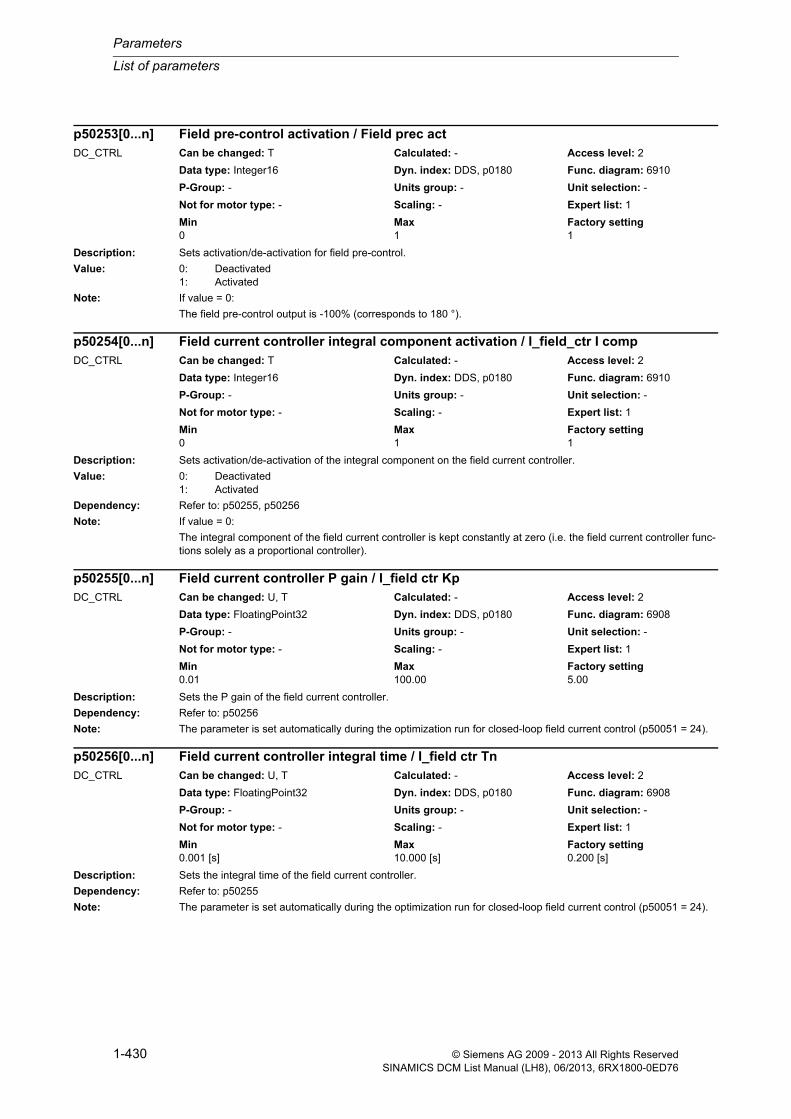
Parameters
List of parameters
1-430 © Siemens AG 2009 - 2013 All Rights ReservedSINAMICS DCM List Manual (LH8), 06/2013, 6RX1800-0ED76
Description: Sets activation/de-activation for field pre-control.
Value: 0: Deactivated1: Activated
Note: If value = 0:
The field pre-control output is -100% (corresponds to 180 °).
Description: Sets activation/de-activation of the integral component on the field current controller.
Value: 0: Deactivated1: Activated
Dependency: Refer to: p50255, p50256
Note: If value = 0:
The integral component of the field current controller is kept constantly at zero (i.e. the field current controller func-tions solely as a proportional controller).
Description: Sets the P gain of the field current controller.
Dependency: Refer to: p50256
Note: The parameter is set automatically during the optimization run for closed-loop field current control (p50051 = 24).
Description: Sets the integral time of the field current controller.
Dependency: Refer to: p50255
Note: The parameter is set automatically during the optimization run for closed-loop field current control (p50051 = 24).
p50253[0...n] Field pre-control activation / Field prec actDC_CTRL Can be changed: T Calculated: - Access level: 2
Data type: Integer16 Dyn. index: DDS, p0180 Func. diagram: 6910
P-Group: - Units group: - Unit selection: -
Not for motor type: - Scaling: - Expert list: 1
Min Max Factory setting 0 1 1
p50254[0...n] Field current controller integral component activation / I_field_ctr I compDC_CTRL Can be changed: T Calculated: - Access level: 2
Data type: Integer16 Dyn. index: DDS, p0180 Func. diagram: 6910
P-Group: - Units group: - Unit selection: -
Not for motor type: - Scaling: - Expert list: 1
Min Max Factory setting 0 1 1
p50255[0...n] Field current controller P gain / I_field ctr KpDC_CTRL Can be changed: U, T Calculated: - Access level: 2
Data type: FloatingPoint32 Dyn. index: DDS, p0180 Func. diagram: 6908
P-Group: - Units group: - Unit selection: -
Not for motor type: - Scaling: - Expert list: 1
Min Max Factory setting 0.01 100.00 5.00
p50256[0...n] Field current controller integral time / I_field ctr TnDC_CTRL Can be changed: U, T Calculated: - Access level: 2
Data type: FloatingPoint32 Dyn. index: DDS, p0180 Func. diagram: 6908
P-Group: - Units group: - Unit selection: -
Not for motor type: - Scaling: - Expert list: 1
Min Max Factory setting 0.001 [s] 10.000 [s] 0.200 [s]

List of parameters
Parameters
1-431© Siemens AG 2009 - 2013 All Rights ReservedSINAMICS DCM List Manual (LH8), 06/2013, 6RX1800-0ED76
Description: Sets the standstill field for closed-loop field current control.
Dependency: Refer to: p50692
Note: The field current is reduced to this value when the "Automatic field current reduction" function is parameterized (p50082 = 2) or in the case of signal-driven selection of the ""Standstill excitation" function (p50692).
Description: Sets the delay time for automatic field current reduction.
Description: Sets the smoothing time constant for the setpoint for field current pre-control.
Dependency: Refer to: p50261
Note: This smoothing enables field-current pre-control to be decoupled from the field current controller.
Description: Sets the smoothing time constant for the setpoint for the field current controller.
Dependency: Refer to: p50260
Note: This smoothing enables field-current pre-control to be decoupled from the field current controller.
Description: Selection of the input variable for determining the motor flux.
p50257[0...n] Closed-loop field current control standstill field / If_ctr stst_fieldDC_CTRL Can be changed: U, T Calculated: - Access level: 2
Data type: FloatingPoint32 Dyn. index: DDS, p0180 Func. diagram: 6910
P-Group: - Units group: - Unit selection: -
Not for motor type: - Scaling: PERCENT Expert list: 1
Min Max Factory setting 0.0 [%] 100.0 [%] 0.0 [%]
p50258[0...n] Cl-loop field current control field current reduction delay time / If_ctr I_red t_delDC_CTRL Can be changed: U, T Calculated: - Access level: 2
Data type: FloatingPoint32 Dyn. index: DDS, p0180 Func. diagram: 6910
P-Group: - Units group: - Unit selection: -
Not for motor type: - Scaling: - Expert list: 1
Min Max Factory setting 0.0 [s] 60.0 [s] 10.0 [s]
p50260[0...n] Field current pre-control setpoint smoothing time constant / Field_prec set TDC_CTRL Can be changed: U, T Calculated: - Access level: 2
Data type: FloatingPoint32 Dyn. index: DDS, p0180 Func. diagram: 6910
P-Group: - Units group: - Unit selection: -
Not for motor type: - Scaling: - Expert list: 1
Min Max Factory setting 0 [ms] 10000 [ms] 0 [ms]
p50261[0...n] Field current controller setpoint smoothing time constant / I_field_ctr set TDC_CTRL Can be changed: U, T Calculated: - Access level: 2
Data type: FloatingPoint32 Dyn. index: DDS, p0180 Func. diagram: 6910
P-Group: - Units group: - Unit selection: -
Not for motor type: - Scaling: - Expert list: 1
Min Max Factory setting 0 [ms] 10000 [ms] 0 [ms]
p50263[0...n] Selection of motor flux input variable / Mot fl input selDC_CTRL Can be changed: T Calculated: - Access level: 2
Data type: Integer16 Dyn. index: DDS, p0180 Func. diagram: 6910
P-Group: - Units group: - Unit selection: -
Not for motor type: - Scaling: - Expert list: 1
Min Max Factory setting 0 2 1

Parameters
List of parameters
1-432 © Siemens AG 2009 - 2013 All Rights ReservedSINAMICS DCM List Manual (LH8), 06/2013, 6RX1800-0ED76
Value: 0: Field current controller actual value (r52265)1: EMF pre-control output (r52293 or r52268)2: Field current controller setpoint (r52268)
Note: If value = 0:
This setting is recommended for a fully compensated DC motor.
If value = 1:
This setting is recommended for an uncompensated DC motor. The EMF controller must be active for this setting (the EMF controller compensates the armature reaction).
If value = 2:
This setting is recommended for a fully compensated DC motor.
Advantage compared with value = 0:
Values derived from the setpoint are generally steadier than those derived from the actual value.
Disadvantage compared with value = 0:
The actual value can deviate from the setpoint dramatically, thereby distorting the motor flux calculation.
Description: Sets activation/de-activation of the proportional component on the field current controller.
Value: 0: Deactivated1: Activated
Dependency: Refer to: p50255, p50256
Note: If value = 0:
The proportional component of the field current controller is kept constantly at zero (i.e. the field current controller functions solely as an integral controller).
Description: Sets the signal source for external monitoring of the field current.
The delay time in p50397 is started after a 1/0 signal and a corresponding fault is triggered once it has elapsed.
Dependency: Refer to: p50397
Description: Sets the signal source for a factor of the integral time Tn for the field current controller.
Dependency: Refer to: p50256
p50264[0...n] Field current controller proportional component activation / I_field_ctr P compDC_CTRL Can be changed: T Calculated: - Access level: 2
Data type: Integer16 Dyn. index: DDS, p0180 Func. diagram: 6910
P-Group: - Units group: - Unit selection: -
Not for motor type: - Scaling: - Expert list: 1
Min Max Factory setting 0 1 1
p50265[0...n] BI: Signal source for field current monitoring / I_field mon sig sDC_CTRL Can be changed: T Calculated: - Access level: 2
Data type: Unsigned32 / Binary Dyn. index: CDS, p0170 Func. diagram: 8044
P-Group: - Units group: - Unit selection: -
Not for motor type: - Scaling: - Expert list: 1
Min Max Factory setting - - 1
p50266[0...n] CI: Field current controller Tn factor signal source / If_ctrTnFact sig sDC_CTRL Can be changed: T Calculated: - Access level: 2
Data type: Unsigned32 / FloatingPoint32 Dyn. index: CDS, p0170 Func. diagram: 6908
P-Group: - Units group: - Unit selection: -
Not for motor type: - Scaling: PERCENT Expert list: 1
Min Max Factory setting - - 1

List of parameters
Parameters
1-433© Siemens AG 2009 - 2013 All Rights ReservedSINAMICS DCM List Manual (LH8), 06/2013, 6RX1800-0ED76
Description: Sets the signal source for a factor of the proportional gain Kp for the field current controller.
Dependency: Refer to: p50255
Description: Sets the operating mode for the "Freeze field current setpoint" function.
Value: 0: Never freeze1: Freeze for tachometer breakage2: Freeze for every fault
Description: Sets activation/de-activation of automatic field current reduction if the EMF is too high for braking operation.
Value: 0: Fault1: Alarm and field reduction
Note: If value = 0:
If the EMF is too high for braking operation, a message is output accordingly.
Description: Sets activation/de-activation for EMF controller pre-control.
Value: 0: Deactivated1: Activated
Note: If value = 0:
The EMF controller's pre-control output is set to 100% (corresponding to the rated excitation current of the motor (p50102)).
p50267[0...n] CI: Field current controller Kp factor signal source / If_ctrKpFact sig sDC_CTRL Can be changed: T Calculated: - Access level: 2
Data type: Unsigned32 / FloatingPoint32 Dyn. index: CDS, p0170 Func. diagram: 6908
P-Group: - Units group: - Unit selection: -
Not for motor type: - Scaling: PERCENT Expert list: 1
Min Max Factory setting - - 1
p50269 Freeze field current setpoint operating mode / If freeze op_modeDC_CTRL Can be changed: U, T Calculated: - Access level: 2
Data type: Integer16 Dyn. index: - Func. diagram: 6905
P-Group: - Units group: - Unit selection: -
Not for motor type: - Scaling: - Expert list: 1
Min Max Factory setting 0 2 2
p50272 Field current reduction activation / I_field_red actDC_CTRL Can be changed: T Calculated: - Access level: 2
Data type: Integer16 Dyn. index: - Func. diagram: 6900
P-Group: - Units group: - Unit selection: -
Not for motor type: - Scaling: - Expert list: 1
Min Max Factory setting 0 1 0
p50273[0...n] EMF controller pre-control activation / EMF ctr prec actDC_CTRL Can be changed: T Calculated: - Access level: 2
Data type: Integer16 Dyn. index: DDS, p0180 Func. diagram: 6900
P-Group: - Units group: - Unit selection: -
Not for motor type: - Scaling: - Expert list: 1
Min Max Factory setting 0 1 1

Parameters
List of parameters
1-434 © Siemens AG 2009 - 2013 All Rights ReservedSINAMICS DCM List Manual (LH8), 06/2013, 6RX1800-0ED76
Description: Sets activation/de-activation of the integral component on the EMF controller.
Value: 0: Deactivated1: Activated
Dependency: Refer to: p50284
Note: If value = 0:
The integral component of the EMF controller is kept constantly at zero (i.e. the EMF controller functions solely as a proportional controller).
Description: Sets the P gain of the EMF controller.
Dependency: Refer to: p50276
Note: The parameter is set automatically during the optimization run for field weakening (p50051 = 27).
Description: Sets the integral time of the EMF controller.
Dependency: Refer to: p50275
Note: The parameter is set automatically during the optimization run for field weakening (p50051 = 27).
Description: Sets the value for the EMF controller's droop feedback.
Note: If value = 0:
Droop feedback is de-activated.
p50274[0...n] EMF controller integral component activation / EMF ctr I comp actDC_CTRL Can be changed: T Calculated: - Access level: 2
Data type: Integer16 Dyn. index: DDS, p0180 Func. diagram: 6900
P-Group: - Units group: - Unit selection: -
Not for motor type: - Scaling: - Expert list: 1
Min Max Factory setting 0 1 1
p50275[0...n] EMF controller P gain / EMF ctr KpDC_CTRL Can be changed: U, T Calculated: - Access level: 2
Data type: FloatingPoint32 Dyn. index: DDS, p0180 Func. diagram: 6900
P-Group: - Units group: - Unit selection: -
Not for motor type: - Scaling: - Expert list: 1
Min Max Factory setting 0.01 100.00 0.60
p50276[0...n] EMF controller integral time / EMF ctr TnDC_CTRL Can be changed: U, T Calculated: - Access level: 2
Data type: FloatingPoint32 Dyn. index: DDS, p0180 Func. diagram: 6900
P-Group: - Units group: - Unit selection: -
Not for motor type: - Scaling: - Expert list: 1
Min Max Factory setting 0.010 [s] 10.000 [s] 0.200 [s]
p50277[0...n] EMF controller droop / EMF ctr droopDC_CTRL Can be changed: U, T Calculated: - Access level: 2
Data type: FloatingPoint32 Dyn. index: DDS, p0180 Func. diagram: 6900
P-Group: - Units group: - Unit selection: -
Not for motor type: - Scaling: PERCENT Expert list: 1
Min Max Factory setting 0.0 [%] 10.0 [%] 0.0 [%]

List of parameters
Parameters
1-435© Siemens AG 2009 - 2013 All Rights ReservedSINAMICS DCM List Manual (LH8), 06/2013, 6RX1800-0ED76
Description: Sets the smoothing time constant for the setpoint for EMF controller pre-control.
Dependency: Refer to: p50283
Note: This smoothing enables the EMF controller pre-control to be decoupled from the EMF controller.
Description: Sets the smoothing time constant for the EMF controller's setpoint.
Dependency: Refer to: p50282
Note: This smoothing enables the EMF controller pre-control to be decoupled from the EMF controller.
Description: Sets the smoothing time constant for the EMF controller's actual value.
Dependency: Refer to: p50281
Note: This smoothing enables the EMF controller pre-control to be decoupled from the EMF controller.
Description: Sets the smoothing time constant for the actual value for EMF controller pre-control.
Dependency: Refer to: p50280
Note: This smoothing enables the EMF controller pre-control to be decoupled from the EMF controller.
p50280[0...n] EMF controller pre-control setpoint smoothing time constant / EMF prec set TDC_CTRL Can be changed: U, T Calculated: - Access level: 2
Data type: FloatingPoint32 Dyn. index: DDS, p0180 Func. diagram: 6900
P-Group: - Units group: - Unit selection: -
Not for motor type: - Scaling: - Expert list: 1
Min Max Factory setting 0 [ms] 10000 [ms] 0 [ms]
p50281[0...n] EMF controller setpoint smoothing time constant / EMF ctr set TDC_CTRL Can be changed: U, T Calculated: - Access level: 2
Data type: FloatingPoint32 Dyn. index: DDS, p0180 Func. diagram: 6900
P-Group: - Units group: - Unit selection: -
Not for motor type: - Scaling: - Expert list: 1
Min Max Factory setting 0 [ms] 10000 [ms] 0 [ms]
p50282[0...n] EMF controller actual value smoothing time constant / EMF ctr act TDC_CTRL Can be changed: U, T Calculated: - Access level: 2
Data type: FloatingPoint32 Dyn. index: DDS, p0180 Func. diagram: 6900
P-Group: - Units group: - Unit selection: -
Not for motor type: - Scaling: - Expert list: 1
Min Max Factory setting 0 [ms] 10000 [ms] 0 [ms]
p50283[0...n] EMF controller pre-control actual value smoothing time constant / EMF prec act TDC_CTRL Can be changed: U, T Calculated: - Access level: 2
Data type: FloatingPoint32 Dyn. index: DDS, p0180 Func. diagram: 6900
P-Group: - Units group: - Unit selection: -
Not for motor type: - Scaling: - Expert list: 1
Min Max Factory setting 0 [ms] 10000 [ms] 0 [ms]

Parameters
List of parameters
1-436 © Siemens AG 2009 - 2013 All Rights ReservedSINAMICS DCM List Manual (LH8), 06/2013, 6RX1800-0ED76
Description: Sets activation/de-activation of the proportional component on the EMF controller.
Value: 0: Deactivated1: Activated
Dependency: Refer to: p50275, p50276
Note: If value = 0:
The proportional component of the EMF controller is kept constantly at zero (i.e. the EMF controller functions solely as an integral controller).
Description: Sets the smoothing time for the line voltage for the EMF setpoint reduction.
Dependency: Refer to: p50286, p50287, p50288, p50289, r52294
Description: Sets the upper limit for the line voltage for EMF setpoint reduction.
Dependency: Refer to: p50287, p50288, p50289, r52294
Description: Sets the lower limit for the line voltage for the EMF setpoint reduction.
Dependency: Refer to: p50286, p50288, p50289, r52294
p50284[0...n] EMF controller proportional component activation / EMF ctr P comp actDC_CTRL Can be changed: T Calculated: - Access level: 2
Data type: Integer16 Dyn. index: DDS, p0180 Func. diagram: 6900
P-Group: - Units group: - Unit selection: -
Not for motor type: - Scaling: - Expert list: 1
Min Max Factory setting 0 1 1
p50285[0...n] EMF setpoint reduction line voltage smoothing time / EMF set line t_smDC_CTRL Can be changed: U, T Calculated: - Access level: 2
Data type: FloatingPoint32 Dyn. index: DDS, p0180 Func. diagram: 6895
P-Group: - Units group: - Unit selection: -
Not for motor type: - Scaling: - Expert list: 1
Min Max Factory setting 0.00 [s] 10.00 [s] 0.00 [s]
p50286[0...n] EMF setpoint reduction line voltage upper limit / EMF set line upperDC_CTRL Can be changed: U, T Calculated: - Access level: 2
Data type: FloatingPoint32 Dyn. index: DDS, p0180 Func. diagram: 6895
P-Group: - Units group: - Unit selection: -
Not for motor type: - Scaling: PERCENT Expert list: 1
Min Max Factory setting 100.0 [%] 150.0 [%] 110.0 [%]
p50287[0...n] EMF setpoint reduction line voltage lower limit / EMF set line lowerDC_CTRL Can be changed: U, T Calculated: - Access level: 2
Data type: FloatingPoint32 Dyn. index: DDS, p0180 Func. diagram: 6895
P-Group: - Units group: - Unit selection: -
Not for motor type: - Scaling: PERCENT Expert list: 1
Min Max Factory setting 0.0 [%] 100.0 [%] 0.0 [%]

List of parameters
Parameters
1-437© Siemens AG 2009 - 2013 All Rights ReservedSINAMICS DCM List Manual (LH8), 06/2013, 6RX1800-0ED76
Description: Sets the evaluation factor for the EMF setpoint reduction.
Dependency: Refer to: p50286, p50287, p50289, r52294
Description: Sets the signal source to activate the EMF setpoint reduction.
Dependency: Refer to: p50285, p50286, p50287, p50288, r52294
Description: Sets the response to setpoint inversion on the ramp-function generator.
Value: 0: Hard setpoint change1: Soft setpoint change
Note: If p50295 = 0:
In the event of setpoint inversion during ramping up, ramp-up is aborted and ramp-down initial rounding com-mences immediately, and vice versa. As the setpoint is not increased (decreased) any further, the signal at the ramp-function generator output has a breakpoint (in other words, there is a step change in the acceleration rate).
If p50295 = 1:
In the event of setpoint inversion during ramping up, ramp-up is slowly switched over to ramp-down, and vice versa. The setpoint increases/decreases further. There is no breakpoint in the signal at the ramp-function generator output (in other words, there is no step change in the acceleration rate).
Description: Sets the ramp-down time for quick stop (OFF3) on the ramp-function generator.
When the "Quick stop" command is sent, the drive is decelerated to zero speed at the current limit.
However, if this is not permissible or desirable for mechanical reasons, a value > 0 must be set in this parameter. The drive will then decelerate along the down ramp set here.
p50288[0...n] EMF setpoint reduction evaluation factor / EMF set eval_factDC_CTRL Can be changed: U, T Calculated: - Access level: 2
Data type: FloatingPoint32 Dyn. index: DDS, p0180 Func. diagram: 6895
P-Group: - Units group: - Unit selection: -
Not for motor type: - Scaling: PERCENT Expert list: 1
Min Max Factory setting 0.0 [%] 200.0 [%] 100.0 [%]
p50289[0...n] BI: EMF setpoint reduction activation signal source / EMF set act sig sDC_CTRL Can be changed: T Calculated: - Access level: 2
Data type: Unsigned32 / Binary Dyn. index: CDS, p0170 Func. diagram: 6895
P-Group: - Units group: - Unit selection: -
Not for motor type: - Scaling: - Expert list: 1
Min Max Factory setting - - 0
p50295[0...n] Transition rounding operating mode / RFG rounding modeDC_CTRL Can be changed: U, T Calculated: - Access level: 2
Data type: Integer16 Dyn. index: DDS, p0180 Func. diagram: 3152
P-Group: - Units group: - Unit selection: -
Not for motor type: - Scaling: - Expert list: 1
Min Max Factory setting 0 1 0
p50296[0...n] RFG quick stop (OFF3) ramp-down time / RFG OFF3 t_ramp-dnDC_CTRL Can be changed: U, T Calculated: - Access level: 2
Data type: FloatingPoint32 Dyn. index: DDS, p0180 Func. diagram: 3150
P-Group: - Units group: - Unit selection: -
Not for motor type: - Scaling: - Expert list: 1
Min Max Factory setting 0.00 [s] 650.00 [s] 0.00 [s]

Parameters
List of parameters
1-438 © Siemens AG 2009 - 2013 All Rights ReservedSINAMICS DCM List Manual (LH8), 06/2013, 6RX1800-0ED76
Description: Sets the initial rounding for quick stop (OFF3) on the ramp-function generator.
Description: Sets the final rounding for quick stop (OFF3) on the ramp-function generator.
Description: Sets positive setpoint limiting after the ramp-function generator.
Description: Sets negative setpoint limiting after the ramp-function generator.
Description: Sets the operating mode for the ramp-up integrator.
The ramp-up integrator controls the changing over of the ramp-function generator parameter sets as appropriate for the set operating mode once the setpoint has been reached for the first time.
Value: 0: RFG normal operation1: Operating mode 12: Operating mode 23: Operating mode 3
p50297[0...n] RFG quick stop (OFF3) initial rounding / RFG OFF3 init rndgDC_CTRL Can be changed: U, T Calculated: - Access level: 2
Data type: FloatingPoint32 Dyn. index: DDS, p0180 Func. diagram: 3150
P-Group: - Units group: - Unit selection: -
Not for motor type: - Scaling: - Expert list: 1
Min Max Factory setting 0.00 [s] 100.00 [s] 0.00 [s]
p50298[0...n] RFG quick stop (OFF3) final rounding / RFG OFF3 fin rndgDC_CTRL Can be changed: U, T Calculated: - Access level: 2
Data type: FloatingPoint32 Dyn. index: DDS, p0180 Func. diagram: 3150
P-Group: - Units group: - Unit selection: -
Not for motor type: - Scaling: - Expert list: 1
Min Max Factory setting 0.00 [s] 100.00 [s] 0.00 [s]
p50300[0...n] RFG positive setpoint limit after ramp-function generator / RFG pos after RFGDC_CTRL Can be changed: U, T Calculated: - Access level: 2
Data type: FloatingPoint32 Dyn. index: DDS, p0180 Func. diagram: 3155
P-Group: - Units group: - Unit selection: -
Not for motor type: - Scaling: PERCENT Expert list: 1
Min Max Factory setting -200.00 [%] 200.00 [%] 100.00 [%]
p50301[0...n] RFG negative setpoint limit after ramp-function generator / RFG neg after RFGDC_CTRL Can be changed: U, T Calculated: - Access level: 2
Data type: FloatingPoint32 Dyn. index: DDS, p0180 Func. diagram: 3155
P-Group: - Units group: - Unit selection: -
Not for motor type: - Scaling: PERCENT Expert list: 1
Min Max Factory setting -200.00 [%] 200.00 [%] -100.00 [%]
p50302[0...n] RFG ramp-up integrator operating mode / RFG integ op modeDC_CTRL Can be changed: T Calculated: - Access level: 2
Data type: Integer16 Dyn. index: DDS, p0180 Func. diagram: 3150
P-Group: - Units group: - Unit selection: -
Not for motor type: - Scaling: - Expert list: 1
Min Max Factory setting 0 3 0

List of parameters
Parameters
1-439© Siemens AG 2009 - 2013 All Rights ReservedSINAMICS DCM List Manual (LH8), 06/2013, 6RX1800-0ED76
Note: If p50302 = 0:
- The parameter sets are not changed over and ramp-function generator setting 1 is always used (or the setting made using p50637, p50638).
If p50302 = 1:
- Once the setpoint has been reached for the first time, the ramp-function generator parameter set is changed over from 1 to 0.
If p50302 = 2:
- Once the setpoint has been reached for the first time, the ramp-function generator parameter set is changed over from 1 to 2.
If p50302 = 3:
- Once the setpoint has been reached for the first time, the ramp-function generator parameter set is changed over from 1 to 3.
Description: Sets the ramp-up time for ramp-function generator parameter set 1.
Note: The parameter is effective in the following cases:
- No quick stop (OFF3) active
- No other ramp-function generator parameter set selected
- No selection via ramp-up integrator
Description: Sets the ramp-down time for ramp-function generator parameter set 1.
Note: The parameter is effective in the following cases:
- No quick stop (OFF3) active
- No other ramp-function generator parameter set selected
- No selection via ramp-up integrator
Description: Sets the initial rounding for ramp-function generator parameter set 1.
Dependency: Refer to: p50295
Note: The parameter is effective in the following cases:
- No quick stop (OFF3) active
- No other ramp-function generator parameter set selected
- No selection via ramp-up integrator
p50303[0...n] RFG ramp-up time 1 / RFG t_ramp-up 1DC_CTRL Can be changed: C2(1), U, T Calculated: - Access level: 1
Data type: FloatingPoint32 Dyn. index: DDS, p0180 Func. diagram: 3150
P-Group: - Units group: - Unit selection: -
Not for motor type: - Scaling: - Expert list: 1
Min Max Factory setting 0.00 [s] 650.00 [s] 10.00 [s]
p50304[0...n] RFG ramp-down time 1 / RFG t_ramp-dn 1DC_CTRL Can be changed: C2(1), U, T Calculated: - Access level: 1
Data type: FloatingPoint32 Dyn. index: DDS, p0180 Func. diagram: 3150
P-Group: - Units group: - Unit selection: -
Not for motor type: - Scaling: - Expert list: 1
Min Max Factory setting 0.00 [s] 650.00 [s] 10.00 [s]
p50305[0...n] RFG initial rounding 1 / RFG init rndg 1DC_CTRL Can be changed: C2(1), U, T Calculated: - Access level: 1
Data type: FloatingPoint32 Dyn. index: DDS, p0180 Func. diagram: 3150
P-Group: - Units group: - Unit selection: -
Not for motor type: - Scaling: - Expert list: 1
Min Max Factory setting 0.00 [s] 100.00 [s] 0.00 [s]

Parameters
List of parameters
1-440 © Siemens AG 2009 - 2013 All Rights ReservedSINAMICS DCM List Manual (LH8), 06/2013, 6RX1800-0ED76
Description: Sets the final rounding for ramp-function generator parameter set 1.
Dependency: Refer to: p50295
Note: The parameter is effective in the following cases:
- No quick stop (OFF3) active
- No other ramp-function generator parameter set selected
- No selection via ramp-up integrator
Description: Sets the ramp-up time for ramp-function generator parameter set 2.
Description: Sets the ramp-down time for ramp-function generator parameter set 2.
Description: Sets the initial rounding for ramp-function generator parameter set 2.
Dependency: Refer to: p50295
Description: Sets the final rounding for ramp-function generator parameter set 2.
Dependency: Refer to: p50295
p50306[0...n] RFG final rounding 1 / RFG fin rndg 1DC_CTRL Can be changed: C2(1), U, T Calculated: - Access level: 1
Data type: FloatingPoint32 Dyn. index: DDS, p0180 Func. diagram: 3150
P-Group: - Units group: - Unit selection: -
Not for motor type: - Scaling: - Expert list: 1
Min Max Factory setting 0.00 [s] 100.00 [s] 0.00 [s]
p50307[0...n] RFG ramp-up time 2 / RFG t_ramp-up 2DC_CTRL Can be changed: U, T Calculated: - Access level: 2
Data type: FloatingPoint32 Dyn. index: DDS, p0180 Func. diagram: 3150
P-Group: - Units group: - Unit selection: -
Not for motor type: - Scaling: - Expert list: 1
Min Max Factory setting 0.00 [s] 650.00 [s] 10.00 [s]
p50308[0...n] RFG ramp-down time 2 / RFG ramp-dn time 2DC_CTRL Can be changed: U, T Calculated: - Access level: 2
Data type: FloatingPoint32 Dyn. index: DDS, p0180 Func. diagram: 3150
P-Group: - Units group: - Unit selection: -
Not for motor type: - Scaling: - Expert list: 1
Min Max Factory setting 0.00 [s] 650.00 [s] 10.00 [s]
p50309[0...n] RFG initial rounding 2 / RFG init rndg 2DC_CTRL Can be changed: U, T Calculated: - Access level: 2
Data type: FloatingPoint32 Dyn. index: DDS, p0180 Func. diagram: 3150
P-Group: - Units group: - Unit selection: -
Not for motor type: - Scaling: - Expert list: 1
Min Max Factory setting 0.00 [s] 100.00 [s] 0.00 [s]
p50310[0...n] RFG final rounding 2 / RFG fin rndg 2DC_CTRL Can be changed: U, T Calculated: - Access level: 2
Data type: FloatingPoint32 Dyn. index: DDS, p0180 Func. diagram: 3150
P-Group: - Units group: - Unit selection: -
Not for motor type: - Scaling: - Expert list: 1
Min Max Factory setting 0.00 [s] 100.00 [s] 0.00 [s]

List of parameters
Parameters
1-441© Siemens AG 2009 - 2013 All Rights ReservedSINAMICS DCM List Manual (LH8), 06/2013, 6RX1800-0ED76
Description: Sets the ramp-up time for ramp-function generator parameter set 3.
Description: Sets the ramp-down time for ramp-function generator parameter set 3.
Description: Sets the initial rounding for ramp-function generator parameter set 3.
Dependency: Refer to: p50295
Description: Sets the final rounding for ramp-function generator parameter set 3.
Dependency: Refer to: p50295
Description: Displays the effective times on the ramp-function generator.
Index: [0] = Ramp-up time[1] = Ramp-down time[2] = Initial rounding[3] = Final rounding
p50311[0...n] RFG ramp-up time 3 / RFG t_ramp-up 3DC_CTRL Can be changed: U, T Calculated: - Access level: 2
Data type: FloatingPoint32 Dyn. index: DDS, p0180 Func. diagram: 3150
P-Group: - Units group: - Unit selection: -
Not for motor type: - Scaling: - Expert list: 1
Min Max Factory setting 0.00 [s] 650.00 [s] 10.00 [s]
p50312[0...n] RFG ramp-down time 3 / RFG t_ramp-dn 3DC_CTRL Can be changed: U, T Calculated: - Access level: 2
Data type: FloatingPoint32 Dyn. index: DDS, p0180 Func. diagram: 3150
P-Group: - Units group: - Unit selection: -
Not for motor type: - Scaling: - Expert list: 1
Min Max Factory setting 0.00 [s] 650.00 [s] 10.00 [s]
p50313[0...n] RFG initial rounding 3 / RFG init rndg 3DC_CTRL Can be changed: U, T Calculated: - Access level: 2
Data type: FloatingPoint32 Dyn. index: DDS, p0180 Func. diagram: 3150
P-Group: - Units group: - Unit selection: -
Not for motor type: - Scaling: - Expert list: 1
Min Max Factory setting 0.00 [s] 100.00 [s] 0.00 [s]
p50314[0...n] RFG final rounding 3 / RFG fin rndg 3DC_CTRL Can be changed: U, T Calculated: - Access level: 2
Data type: FloatingPoint32 Dyn. index: DDS, p0180 Func. diagram: 3150
P-Group: - Units group: - Unit selection: -
Not for motor type: - Scaling: - Expert list: 1
Min Max Factory setting 0.00 [s] 100.00 [s] 0.00 [s]
r50315[0...3] RFG effective times / RFG t effectiveDC_CTRL Can be changed: - Calculated: - Access level: 1
Data type: FloatingPoint32 Dyn. index: - Func. diagram: 3150
P-Group: - Units group: - Unit selection: -
Not for motor type: - Scaling: - Expert list: 1
Min Max Factory setting - [s] - [s] - [s]

Parameters
List of parameters
1-442 © Siemens AG 2009 - 2013 All Rights ReservedSINAMICS DCM List Manual (LH8), 06/2013, 6RX1800-0ED76
Description: Displays the state on the ramp-function generator.
Description: Sets the enable for ramp-function generator tracking.
Value: 0: Inhibit1: Enable
Dependency: RFG tracking has to be controlled by setting a 1 signal at binector input p50647.
Refer to: p50647
Description: Selection of the setting value for the ramp-function generator output for OFF1.
Value: 0: Ramp-function generator output not set1: Set RFG output to setting value 12: Set RFG output to setting value 2
Recommend.: During "shutdown", limiting is not applied to the ramp-function generator output. As limiting the ramp-function gen-erator output during "shutdown" does not generate a temporary increase in speed, p50318 should be set to 1 or 2.
Dependency: Refer to: p50650
Note: If p50318 = 0:
The ramp-function generator output is not set.
If p50318 = 1:
The value supplied via connector input p50650[0] is applied as the setting value.
If p50318 = 2:
The value supplied via connector input p50650[1] is applied as the setting value.
r50316 RFG state / RFG stateDC_CTRL Can be changed: - Calculated: - Access level: 1
Data type: Unsigned16 Dyn. index: - Func. diagram: 3152
P-Group: - Units group: - Unit selection: -
Not for motor type: - Scaling: - Expert list: 1
Min Max Factory setting - - -
Bit field: Bit Signal name 1 signal 0 signal FP00 RFG enable ON OFF 315201 RFG start ON OFF 315202 Setpoint enable & OFF1 ON OFF 315203 Set ramp-function generator ON OFF 315204 Track ramp-function generator ON OFF 315205 Bypass ramp-function generator ON OFF 315207 Ramp-down ON OFF 315215 Ramp-up ON OFF 3152
p50317[0...n] RFG tracking enable / RFG track enaDC_CTRL Can be changed: T Calculated: - Access level: 2
Data type: Integer16 Dyn. index: DDS, p0180 Func. diagram: 3152
P-Group: - Units group: - Unit selection: -
Not for motor type: - Scaling: - Expert list: 1
Min Max Factory setting 0 1 0
p50318[0...n] RFG setting value selection / RFG set val selDC_CTRL Can be changed: T Calculated: - Access level: 2
Data type: Integer16 Dyn. index: DDS, p0180 Func. diagram: 3152
P-Group: - Units group: - Unit selection: -
Not for motor type: - Scaling: - Expert list: 1
Min Max Factory setting 0 2 0
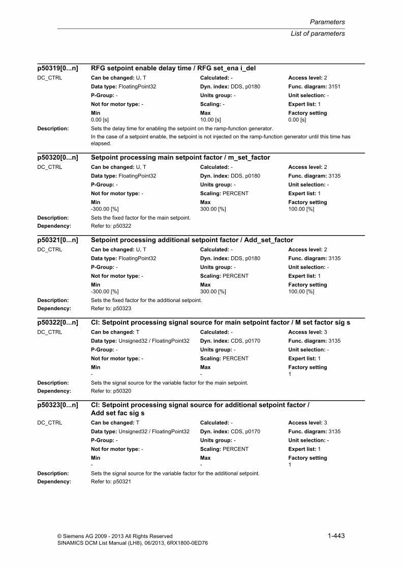
List of parameters
Parameters
1-443© Siemens AG 2009 - 2013 All Rights ReservedSINAMICS DCM List Manual (LH8), 06/2013, 6RX1800-0ED76
Description: Sets the delay time for enabling the setpoint on the ramp-function generator.
In the case of a setpoint enable, the setpoint is not injected on the ramp-function generator until this time has elapsed.
Description: Sets the fixed factor for the main setpoint.
Dependency: Refer to: p50322
Description: Sets the fixed factor for the additional setpoint.
Dependency: Refer to: p50323
Description: Sets the signal source for the variable factor for the main setpoint.
Dependency: Refer to: p50320
Description: Sets the signal source for the variable factor for the additional setpoint.
Dependency: Refer to: p50321
p50319[0...n] RFG setpoint enable delay time / RFG set_ena i_delDC_CTRL Can be changed: U, T Calculated: - Access level: 2
Data type: FloatingPoint32 Dyn. index: DDS, p0180 Func. diagram: 3151
P-Group: - Units group: - Unit selection: -
Not for motor type: - Scaling: - Expert list: 1
Min Max Factory setting 0.00 [s] 10.00 [s] 0.00 [s]
p50320[0...n] Setpoint processing main setpoint factor / m_set_factorDC_CTRL Can be changed: U, T Calculated: - Access level: 2
Data type: FloatingPoint32 Dyn. index: DDS, p0180 Func. diagram: 3135
P-Group: - Units group: - Unit selection: -
Not for motor type: - Scaling: PERCENT Expert list: 1
Min Max Factory setting -300.00 [%] 300.00 [%] 100.00 [%]
p50321[0...n] Setpoint processing additional setpoint factor / Add_set_factorDC_CTRL Can be changed: U, T Calculated: - Access level: 2
Data type: FloatingPoint32 Dyn. index: DDS, p0180 Func. diagram: 3135
P-Group: - Units group: - Unit selection: -
Not for motor type: - Scaling: PERCENT Expert list: 1
Min Max Factory setting -300.00 [%] 300.00 [%] 100.00 [%]
p50322[0...n] CI: Setpoint processing signal source for main setpoint factor / M set factor sig sDC_CTRL Can be changed: T Calculated: - Access level: 3
Data type: Unsigned32 / FloatingPoint32 Dyn. index: CDS, p0170 Func. diagram: 3135
P-Group: - Units group: - Unit selection: -
Not for motor type: - Scaling: PERCENT Expert list: 1
Min Max Factory setting - - 1
p50323[0...n] CI: Setpoint processing signal source for additional setpoint factor / Add set fac sig s
DC_CTRL Can be changed: T Calculated: - Access level: 3
Data type: Unsigned32 / FloatingPoint32 Dyn. index: CDS, p0170 Func. diagram: 3135
P-Group: - Units group: - Unit selection: -
Not for motor type: - Scaling: PERCENT Expert list: 1
Min Max Factory setting - - 1

Parameters
List of parameters
1-444 © Siemens AG 2009 - 2013 All Rights ReservedSINAMICS DCM List Manual (LH8), 06/2013, 6RX1800-0ED76
Description: Sets the unit for the ramp-function generator times.
Value: 0: Second1: Minute
Note: This time unit is applied to the following parameters:
p50296, p50297, p50298:
- Ramp-down time 4, initial rounding 4, final rounding 4
p50303, p50304, p50305, p50306:
- Ramp-up time 1, ramp-down time 1, initial rounding 1, final rounding 1
p50307, p50308, p50309, p50310:
- Ramp-up time 2, ramp-down time 2, initial rounding 2, final rounding 2
p50311, p50312, p50313, p50314:
- Ramp-up time 3, ramp-down time 3, initial rounding 3, final rounding 3
p50542:
- RFG dy/dt time difference
Description: Sets the Encoder Data Set (EDS) used to calculate the braking distance (r52047, r52048).
Description: Sets the threshold for detecting line undervoltage for armature or field.
Note: If the line voltage deviates by a higher value and does not fall back within the tolerance limits by the end of the restart time set in p50086, fault F60006 is triggered.
During the time of excess deviation, the drive is kept in operating state "o4".
For "optimization run for CCP" (p50051 = 30) the parameter is automatically set to -20% if the actual value is less than -20%.
p50330[0...n] RFG time unit / RFG time unitDC_CTRL Can be changed: T Calculated: - Access level: 2
Data type: Integer16 Dyn. index: DDS, p0180 Func. diagram: 3150, 3152
P-Group: - Units group: - Unit selection: -
Not for motor type: - Scaling: - Expert list: 1
Min Max Factory setting 0 1 0
p50331 Braking distance Encoder Data Set selection / Br dist EDS selDC_CTRL Can be changed: T Calculated: - Access level: 3
Data type: Unsigned8 Dyn. index: - Func. diagram: 3152
P-Group: - Units group: - Unit selection: -
Not for motor type: - Scaling: - Expert list: 1
Min Max Factory setting 0 15 0
p50351[0...n] Line undervoltage threshold / Line V_und threshDC_CTRL Can be changed: U, T Calculated: - Access level: 2
Data type: FloatingPoint32 Dyn. index: DDS, p0180 Func. diagram: 6954
P-Group: - Units group: - Unit selection: -
Not for motor type: - Scaling: PERCENT Expert list: 1
Min Max Factory setting -97 [%] 0 [%] -20 [%]

List of parameters
Parameters
1-445© Siemens AG 2009 - 2013 All Rights ReservedSINAMICS DCM List Manual (LH8), 06/2013, 6RX1800-0ED76
Description: Sets the threshold for detecting line undervoltage for armature or field.
Note: If the line voltage deviates by a higher value and does not fall back within the tolerance limits by the end of the restart time set in p50086, fault F60007 is triggered.
During the time of excess deviation, the drive is kept in operating state "o4".
Description: Sets the threshold for phase failure detection in the context of line monitoring.
Note: If the line voltage in operating states <= o4 undershoots the setting value and does not adopt an "OK" state within the restart time set in p50086, fault F60004 is triggered.
During the time that the threshold value is undershot and the voltage stabilization time which follows (set in p50090), the drive is kept in operating state o4.
If the drive is switched on in operating state o4, the voltages of all phases will not be checked for compliance with this threshold until the time set in p50089 has elapsed.
Description: Sets the signal source to activate stall protection.
Dependency: Refer to: p50355, p50356
Note: 1 signal: Stall protection activated
0 signal: Stall protection de-activated
Description: Sets the monitoring time for stall protection.
The set time starts when a stalled drive is detected. If these conditions still prevail once the time has elapsed, stall protection is activated and fault F60035 is triggered.
Dependency: Refer to: p50354, p50356
Note: "Stall protection" monitoring is switched off when p50355 = 0.00 s.
p50352[0...n] Line overvoltage threshold / Line V_over threshDC_CTRL Can be changed: U, T Calculated: - Access level: 2
Data type: FloatingPoint32 Dyn. index: DDS, p0180 Func. diagram: 6954
P-Group: - Units group: - Unit selection: -
Not for motor type: - Scaling: PERCENT Expert list: 1
Min Max Factory setting 0 [%] 99 [%] 20 [%]
p50353[0...n] Line monitoring phase failure threshold / Ph_fail threshDC_CTRL Can be changed: U, T Calculated: - Access level: 2
Data type: FloatingPoint32 Dyn. index: DDS, p0180 Func. diagram: 6954
P-Group: - Units group: - Unit selection: -
Not for motor type: - Scaling: PERCENT Expert list: 1
Min Max Factory setting 3 [%] 100 [%] 40 [%]
p50354 BI: Stall protection activation signal source / Stall pr act sig sDC_CTRL Can be changed: T Calculated: - Access level: 2
Data type: Unsigned32 / Binary Dyn. index: - Func. diagram: 8046
P-Group: - Units group: - Unit selection: -
Not for motor type: - Scaling: - Expert list: 1
Min Max Factory setting - - 0
p50355[0...n] Stall protection monitoring time / Stall t_monDC_CTRL Can be changed: U, T Calculated: - Access level: 2
Data type: FloatingPoint32 Dyn. index: DDS, p0180 Func. diagram: 8046
P-Group: - Units group: - Unit selection: -
Not for motor type: - Scaling: - Expert list: 1
Min Max Factory setting 0.0 [s] 600.0 [s] 0.5 [s]

Parameters
List of parameters
1-446 © Siemens AG 2009 - 2013 All Rights ReservedSINAMICS DCM List Manual (LH8), 06/2013, 6RX1800-0ED76
Description: Sets the speed threshold for stall protection.
Dependency: Refer to: p50355
Description: Sets the threshold for tachometer interruption monitoring.
Note: For p50357 = 100 %, the tachometer interruption monitoring is not active!
Description: Sets the delay time for undervoltage detection in the context of line monitoring.
Note: This time starts when undervoltage is detected. While this delay time is running, firing pulses are emitted; at the end of this time, fault F60006 is triggered.
If a time has been set for automatic restart (p50086), it will not begin until the time set here has elapsed.
Description: Sets the delay time for overvoltage monitoring in the context of line monitoring.
Note: The triggering of fault F60007 (line overvoltage) is delayed by the time set at this parameter.
Firing pulses are emitted while this time is running. If a time has been set for automatic restart (p50086), it will not begin until the time set here has elapsed.
Description: Sets the threshold for detecting that the line frequency has been undershot.
p50356[0...n] Stall protection threshold / Stall prot threshDC_CTRL Can be changed: U, T Calculated: - Access level: 2
Data type: FloatingPoint32 Dyn. index: DDS, p0180 Func. diagram: 8046
P-Group: - Units group: - Unit selection: -
Not for motor type: - Scaling: - Expert list: 1
Min Max Factory setting 0.0 [%] 10.0 [%] 0.4 [%]
p50357[0...n] Tachometer interruption monitoring threshold / Tacho_mon threshDC_CTRL Can be changed: U, T Calculated: - Access level: 2
Data type: FloatingPoint32 Dyn. index: DDS, p0180 Func. diagram: 8046
P-Group: - Units group: - Unit selection: -
Not for motor type: - Scaling: PERCENT Expert list: 1
Min Max Factory setting 10 [%] 100 [%] 10 [%]
p50361[0...n] Line monitoring undervoltage delay time / V_under t_delDC_CTRL Can be changed: U, T Calculated: - Access level: 2
Data type: FloatingPoint32 Dyn. index: DDS, p0180 Func. diagram: 6954
P-Group: - Units group: - Unit selection: -
Not for motor type: - Scaling: - Expert list: 1
Min Max Factory setting 0 [ms] 60000 [ms] 0 [ms]
p50362[0...n] Line monitoring overvoltage delay time / Line V_over t_delDC_CTRL Can be changed: U, T Calculated: - Access level: 2
Data type: FloatingPoint32 Dyn. index: DDS, p0180 Func. diagram: 6954
P-Group: - Units group: - Unit selection: -
Not for motor type: - Scaling: - Expert list: 1
Min Max Factory setting 0 [ms] 60000 [ms] 0 [ms]
p50363[0...n] Line frequency minimum threshold / f_line min threshDC_CTRL Can be changed: U, T Calculated: - Access level: 2
Data type: FloatingPoint32 Dyn. index: DDS, p0180 Func. diagram: 6954
P-Group: - Units group: - Unit selection: -
Not for motor type: - Scaling: - Expert list: 1
Min Max Factory setting 23.0 [Hz] 60.0 [Hz] 45.0 [Hz]

List of parameters
Parameters
1-447© Siemens AG 2009 - 2013 All Rights ReservedSINAMICS DCM List Manual (LH8), 06/2013, 6RX1800-0ED76
Note: If the line frequency undershoots the value set here and does not rise back above it within the restart time set in p50086, fault F60008 is triggered.
All the while the line frequency remains lower than the value set here, the drive is kept in operating state "o4".
Description: Sets the threshold for detecting that the line frequency has been overshot.
Caution: SINAMICS DCM DC converters are suitable for line frequencies from 20 Hz up to 120 Hz.
The SINAMICS DCM Control Module is suitable for line frequencies from 20 Hz up to 500 Hz if it is operated with a power unit designed for this frequency range.
For a SINAMICS DCM DC converter, this parameter may only be set to a maximum value of 120 Hz!
If a SINAMICS DCM DC converter were to be operated with a line frequency above 120 Hz, then it would be dam-aged or destroyed as a result of overheating.
Note: If the line frequency overshoots the value set here and does not fall back below it within the restart time set in p50086, fault F60009 is triggered.
All the while the line frequency remains higher than the value set here, the drive is kept in operating state "o4".
Description: Sets the signal source for speed-dependent current limitation and current limitation from I2t monitoring.
Note: [0] = Speed-dependent current limitation
[1] = Current limitation from I2t monitoring
Description: Sets the threshold for the "Speed less then minimum speed" message.
Dependency: Refer to: p50371, p50593, r53025
Note: The "Speed less than minimum speed" message is available as follows:
- r53025.6 (not inverted)
- r53025.7 (inverted)
p50364[0...n] Line frequency maximum threshold / f_line max threshDC_CTRL Can be changed: U, T Calculated: - Access level: 2
Data type: FloatingPoint32 Dyn. index: DDS, p0180 Func. diagram: 6954
P-Group: - Units group: - Unit selection: -
Not for motor type: - Scaling: - Expert list: 1
Min Max Factory setting 50.0 [Hz] 500.0 [Hz] 65.0 [Hz]
p50366[0...1] CI: Current limitation signal source for speed and I2t monitoring / Ia lim n I2t sig sDC_CTRL Can be changed: U, T Calculated: - Access level: 3
Data type: Unsigned32 / FloatingPoint32 Dyn. index: - Func. diagram: 6840
P-Group: - Units group: - Unit selection: -
Not for motor type: - Scaling: PERCENT Expert list: 1
Min Max Factory setting - - [0] 52129[0]
[1] 52130[0]
p50370[0...n] Messages for speed less than minimum speed threshold / n < n_min threshDC_CTRL Can be changed: U, T Calculated: - Access level: 2
Data type: FloatingPoint32 Dyn. index: DDS, p0180 Func. diagram: 8020
P-Group: - Units group: - Unit selection: -
Not for motor type: - Scaling: PERCENT Expert list: 1
Min Max Factory setting 0.00 [%] 200.00 [%] 0.50 [%]

Parameters
List of parameters
1-448 © Siemens AG 2009 - 2013 All Rights ReservedSINAMICS DCM List Manual (LH8), 06/2013, 6RX1800-0ED76
Description: Sets the hysteresis for the "Speed less then minimum speed" message.
The message is triggered when the threshold is undershot.
Once the value rises above the threshold plus the hysteresis, the message is withdrawn.
Dependency: Refer to: p50370, p50593, r53025
Note: The "Speed less than minimum speed reached" message is available as follows:
- r53025.6 (not inverted)
- r53025.7 (inverted)
Description: Sets the hysteresis for the "Speed positive" message.
This parameter acts on the "Speed setpoint positive" message as well as on the "Speed actual value positive" mes-sage.
Dependency: Refer to: p50594, p50598, r53025
Note: The "Speed positive" message is available as follows:
Setpoint:
- r53025.8 (not inverted)
- r53025.9 (inverted)
Actual value:
- r53025.12 (not inverted)
- r53025.13 (inverted)
Description: Sets the threshold for the "Reference speed reached" message.
Dependency: Refer to: p50374, p50375, p50592, r53025
Note: The "Reference speed reached" message is available as follows:
- r53025.4 (not inverted)
- r53025.5 (inverted)
p50371[0...n] Messages for speed less than minimum speed hysteresis / n < n_min hystDC_CTRL Can be changed: U, T Calculated: - Access level: 2
Data type: FloatingPoint32 Dyn. index: DDS, p0180 Func. diagram: 8020
P-Group: - Units group: - Unit selection: -
Not for motor type: - Scaling: PERCENT Expert list: 1
Min Max Factory setting 0.00 [%] 200.00 [%] 0.50 [%]
p50372[0...n] Messages speed positive hysteresis / Msg n > 0 hystDC_CTRL Can be changed: U, T Calculated: - Access level: 2
Data type: FloatingPoint32 Dyn. index: DDS, p0180 Func. diagram: 8025
P-Group: - Units group: - Unit selection: -
Not for motor type: - Scaling: PERCENT Expert list: 1
Min Max Factory setting 0.00 [%] 10.00 [%] 0.10 [%]
p50373[0...n] Messages for reference speed threshold / Ref_speed threshDC_CTRL Can be changed: U, T Calculated: - Access level: 2
Data type: FloatingPoint32 Dyn. index: DDS, p0180 Func. diagram: 8020
P-Group: - Units group: - Unit selection: -
Not for motor type: - Scaling: PERCENT Expert list: 1
Min Max Factory setting 0.00 [%] 200.00 [%] 100.00 [%]

List of parameters
Parameters
1-449© Siemens AG 2009 - 2013 All Rights ReservedSINAMICS DCM List Manual (LH8), 06/2013, 6RX1800-0ED76
Description: Sets the hysteresis for the "Reference speed reached" message.
The message is triggered when the threshold is overshot.
Once the value falls below the threshold minus the hysteresis, the message is withdrawn.
Dependency: Refer to: p50373, p50375, p50592, r53025
Description: Sets the OFF delay for the "Reference speed reached" message.
Dependency: Refer to: p50373, p50374, p50592, r53025
Description: Sets the threshold for the "Setpoint/actual value deviation 2 reached" message.
Dependency: Refer to: p50377, p50378, p50596, p50597, r53025
Note: The "Setpoint/actual value deviation 2 reached" message is available as follows:
- r53025.2 (not inverted)
- r53025.3 (inverted)
Description: Sets the hysteresis for the "Setpoint/actual value deviation 2 reached" message.
The message is triggered when the threshold is overshot.
Once the value falls below the threshold minus the hysteresis, the message is withdrawn.
Dependency: Refer to: p50376, p50378, p50596, p50597, r53025
p50374[0...n] Messages for reference speed hysteresis / Ref_speed hystDC_CTRL Can be changed: U, T Calculated: - Access level: 2
Data type: FloatingPoint32 Dyn. index: DDS, p0180 Func. diagram: 8020
P-Group: - Units group: - Unit selection: -
Not for motor type: - Scaling: PERCENT Expert list: 1
Min Max Factory setting 0.00 [%] 200.00 [%] 3.00 [%]
p50375[0...n] Messages for reference speed OFF delay / Ref_speed t_OFFDC_CTRL Can be changed: U, T Calculated: - Access level: 2
Data type: FloatingPoint32 Dyn. index: DDS, p0180 Func. diagram: 8020
P-Group: - Units group: - Unit selection: -
Not for motor type: - Scaling: - Expert list: 1
Min Max Factory setting 0.0 [s] 100.0 [s] 3.0 [s]
p50376[0...n] Messages for setpoint/actual value deviation 2 threshold / Set/act 2 threshDC_CTRL Can be changed: U, T Calculated: - Access level: 2
Data type: FloatingPoint32 Dyn. index: DDS, p0180 Func. diagram: 8020
P-Group: - Units group: - Unit selection: -
Not for motor type: - Scaling: PERCENT Expert list: 1
Min Max Factory setting 0.00 [%] 200.00 [%] 3.00 [%]
p50377[0...n] Messages for setpoint/actual value deviation 2 hysteresis / Set/act 2 hystDC_CTRL Can be changed: U, T Calculated: - Access level: 2
Data type: FloatingPoint32 Dyn. index: DDS, p0180 Func. diagram: 8020
P-Group: - Units group: - Unit selection: -
Not for motor type: - Scaling: PERCENT Expert list: 1
Min Max Factory setting 0.00 [%] 200.00 [%] 1.00 [%]

Parameters
List of parameters
1-450 © Siemens AG 2009 - 2013 All Rights ReservedSINAMICS DCM List Manual (LH8), 06/2013, 6RX1800-0ED76
Description: Sets the OFF delay for the "Setpoint/actual value deviation 2 reached" message.
Dependency: Refer to: p50376, p50377, p50596, p50597, r53025
Description: Sets the threshold for the maximum speed in positive direction of rotation.
Dependency: Refer to: p50381, p50595, r53025
Note: The "Overspeed" message is available as follows:
- F60038
- r53025.10 (not inverted)
- r53025.11 (inverted)
Description: Sets the threshold for the maximum speed in negative direction of rotation.
Dependency: Refer to: p50380, p50595, r53025
Note: The "Overspeed" message is available as follows:
- F60038
- r53025.10 (not inverted)
- r53025.11 (inverted)
Description: Sets the threshold for the "Setpoint/actual value deviation 1 reached" message.
Dependency: Refer to: p50389, p50390, p50590, p50591, r53025
Note: The "Setpoint/actual value deviation 1 reached" message is available as follows:
- F60031
- r53025.0 (not inverted)
- r53025.1 (inverted)
p50378[0...n] Messages for setpoint/actual value deviation 2 OFF delay / Set/act 2 t_OFFDC_CTRL Can be changed: U, T Calculated: - Access level: 2
Data type: FloatingPoint32 Dyn. index: DDS, p0180 Func. diagram: 8020
P-Group: - Units group: - Unit selection: -
Not for motor type: - Scaling: - Expert list: 1
Min Max Factory setting 0.0 [s] 100.0 [s] 3.0 [s]
p50380[0...n] Messages for overspeed threshold positive direction of rotation / Msg n_over posDC_CTRL Can be changed: U, T Calculated: - Access level: 2
Data type: FloatingPoint32 Dyn. index: DDS, p0180 Func. diagram: 8025
P-Group: - Units group: - Unit selection: -
Not for motor type: - Scaling: PERCENT Expert list: 1
Min Max Factory setting 0.0 [%] 200.0 [%] 120.0 [%]
p50381[0...n] Messages for overspeed threshold negative direction of rotation / Msg n_over negDC_CTRL Can be changed: U, T Calculated: - Access level: 2
Data type: FloatingPoint32 Dyn. index: DDS, p0180 Func. diagram: 8025
P-Group: - Units group: - Unit selection: -
Not for motor type: - Scaling: PERCENT Expert list: 1
Min Max Factory setting -200.0 [%] 0.0 [%] -120.0 [%]
p50388[0...n] Messages for setpoint/actual value deviation 1 threshold / Set/act 1 threshDC_CTRL Can be changed: U, T Calculated: - Access level: 2
Data type: FloatingPoint32 Dyn. index: DDS, p0180 Func. diagram: 8020
P-Group: - Units group: - Unit selection: -
Not for motor type: - Scaling: PERCENT Expert list: 1
Min Max Factory setting 0.00 [%] 200.00 [%] 3.00 [%]
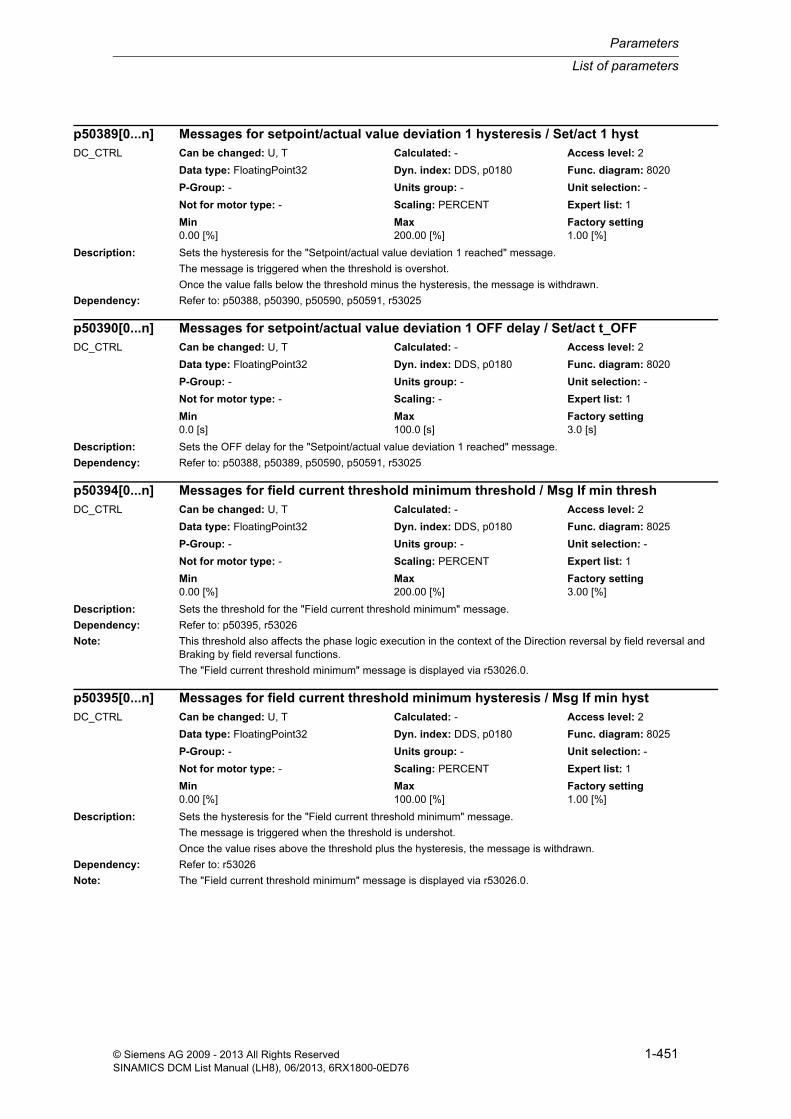
List of parameters
Parameters
1-451© Siemens AG 2009 - 2013 All Rights ReservedSINAMICS DCM List Manual (LH8), 06/2013, 6RX1800-0ED76
Description: Sets the hysteresis for the "Setpoint/actual value deviation 1 reached" message.
The message is triggered when the threshold is overshot.
Once the value falls below the threshold minus the hysteresis, the message is withdrawn.
Dependency: Refer to: p50388, p50390, p50590, p50591, r53025
Description: Sets the OFF delay for the "Setpoint/actual value deviation 1 reached" message.
Dependency: Refer to: p50388, p50389, p50590, p50591, r53025
Description: Sets the threshold for the "Field current threshold minimum" message.
Dependency: Refer to: p50395, r53026
Note: This threshold also affects the phase logic execution in the context of the Direction reversal by field reversal and Braking by field reversal functions.
The "Field current threshold minimum" message is displayed via r53026.0.
Description: Sets the hysteresis for the "Field current threshold minimum" message.
The message is triggered when the threshold is undershot.
Once the value rises above the threshold plus the hysteresis, the message is withdrawn.
Dependency: Refer to: r53026
Note: The "Field current threshold minimum" message is displayed via r53026.0.
p50389[0...n] Messages for setpoint/actual value deviation 1 hysteresis / Set/act 1 hystDC_CTRL Can be changed: U, T Calculated: - Access level: 2
Data type: FloatingPoint32 Dyn. index: DDS, p0180 Func. diagram: 8020
P-Group: - Units group: - Unit selection: -
Not for motor type: - Scaling: PERCENT Expert list: 1
Min Max Factory setting 0.00 [%] 200.00 [%] 1.00 [%]
p50390[0...n] Messages for setpoint/actual value deviation 1 OFF delay / Set/act t_OFFDC_CTRL Can be changed: U, T Calculated: - Access level: 2
Data type: FloatingPoint32 Dyn. index: DDS, p0180 Func. diagram: 8020
P-Group: - Units group: - Unit selection: -
Not for motor type: - Scaling: - Expert list: 1
Min Max Factory setting 0.0 [s] 100.0 [s] 3.0 [s]
p50394[0...n] Messages for field current threshold minimum threshold / Msg If min threshDC_CTRL Can be changed: U, T Calculated: - Access level: 2
Data type: FloatingPoint32 Dyn. index: DDS, p0180 Func. diagram: 8025
P-Group: - Units group: - Unit selection: -
Not for motor type: - Scaling: PERCENT Expert list: 1
Min Max Factory setting 0.00 [%] 200.00 [%] 3.00 [%]
p50395[0...n] Messages for field current threshold minimum hysteresis / Msg If min hystDC_CTRL Can be changed: U, T Calculated: - Access level: 2
Data type: FloatingPoint32 Dyn. index: DDS, p0180 Func. diagram: 8025
P-Group: - Units group: - Unit selection: -
Not for motor type: - Scaling: PERCENT Expert list: 1
Min Max Factory setting 0.00 [%] 100.00 [%] 1.00 [%]

Parameters
List of parameters
1-452 © Siemens AG 2009 - 2013 All Rights ReservedSINAMICS DCM List Manual (LH8), 06/2013, 6RX1800-0ED76
Description: Sets the factor for the setpoint in the context of field current monitoring.
Dependency: Refer to: p50265, p50397
Description: Sets the delay time for triggering fault F60005 in the context of field current monitoring.
Dependency: Refer to: p50265, p50396
Description: Sets the factor for the setpoint for the "Field current actual value less than setpoint" message.
Dependency: Refer to: p50399, r53026
Note: This threshold also affects the phase logic execution in the context of the Direction reversal by field reversal and Braking by field reversal functions.
The "Field current actual value less than setpoint" message is displayed via r53026.1.
Description: Sets the hysteresis for the "Field current actual value less than setpoint" message.
The message is triggered when the threshold is undershot (setpoint x factor).
Once the value rises above the threshold (setpoint x factor) plus the hysteresis, the message is withdrawn.
Dependency: Refer to: p50398, r53026
Note: The "Field current actual value less than setpoint" message is displayed via r53026.1.
p50396[0...n] Field current monitoring setpoint factor / If_mon set_factDC_CTRL Can be changed: U, T Calculated: - Access level: 2
Data type: FloatingPoint32 Dyn. index: DDS, p0180 Func. diagram: 8044
P-Group: - Units group: - Unit selection: -
Not for motor type: - Scaling: PERCENT Expert list: 1
Min Max Factory setting 1 [%] 100 [%] 50 [%]
p50397[0...n] Field current monitoring fault delay time / If_mon F t_delDC_CTRL Can be changed: U, T Calculated: - Access level: 2
Data type: FloatingPoint32 Dyn. index: DDS, p0180 Func. diagram: 8044
P-Group: - Units group: - Unit selection: -
Not for motor type: - Scaling: - Expert list: 1
Min Max Factory setting 0.02 [s] 60.00 [s] 0.50 [s]
p50398[0...n] Messages for field current actual value less than setpoint fact / Msg If<set factDC_CTRL Can be changed: U, T Calculated: - Access level: 2
Data type: FloatingPoint32 Dyn. index: DDS, p0180 Func. diagram: 8025
P-Group: - Units group: - Unit selection: -
Not for motor type: - Scaling: PERCENT Expert list: 1
Min Max Factory setting 0.00 [%] 200.00 [%] 80.00 [%]
p50399[0...n] Messages for field current actual value less than setpoint hyst / Msg If<set hystDC_CTRL Can be changed: U, T Calculated: - Access level: 2
Data type: FloatingPoint32 Dyn. index: DDS, p0180 Func. diagram: 8025
P-Group: - Units group: - Unit selection: -
Not for motor type: - Scaling: PERCENT Expert list: 1
Min Max Factory setting 0.00 [%] 100.00 [%] 1.00 [%]

List of parameters
Parameters
1-453© Siemens AG 2009 - 2013 All Rights ReservedSINAMICS DCM List Manual (LH8), 06/2013, 6RX1800-0ED76
Description: Sets fixed value 1.
Dependency: Refer to: r52401
Note: This value can be interconnected via connector output r52401.
Description: Sets fixed value 2.
Dependency: Refer to: r52402
Note: This value can be interconnected via connector output r52402.
Description: Sets fixed value 3.
Dependency: Refer to: r52403
Note: This value can be interconnected via connector output r52403.
Description: Sets fixed value 4.
Dependency: Refer to: r52404
Note: This value can be interconnected via connector output r52404.
p50401[0...n] Fixed value 1 / Fix val 1DC_CTRL Can be changed: U, T Calculated: - Access level: 2
Data type: FloatingPoint32 Dyn. index: DDS, p0180 Func. diagram: 3100
P-Group: - Units group: - Unit selection: -
Not for motor type: - Scaling: PERCENT Expert list: 1
Min Max Factory setting -200.00 [%] 200.00 [%] 0.00 [%]
p50402[0...n] Fixed value 2 / Fix val 2DC_CTRL Can be changed: U, T Calculated: - Access level: 2
Data type: FloatingPoint32 Dyn. index: DDS, p0180 Func. diagram: 3100
P-Group: - Units group: - Unit selection: -
Not for motor type: - Scaling: PERCENT Expert list: 1
Min Max Factory setting -200.00 [%] 200.00 [%] 0.00 [%]
p50403[0...n] Fixed value 3 / Fix val 3DC_CTRL Can be changed: U, T Calculated: - Access level: 2
Data type: FloatingPoint32 Dyn. index: DDS, p0180 Func. diagram: 3100
P-Group: - Units group: - Unit selection: -
Not for motor type: - Scaling: PERCENT Expert list: 1
Min Max Factory setting -200.00 [%] 200.00 [%] 0.00 [%]
p50404[0...n] Fixed value 4 / Fix val 4DC_CTRL Can be changed: U, T Calculated: - Access level: 2
Data type: FloatingPoint32 Dyn. index: DDS, p0180 Func. diagram: 3100
P-Group: - Units group: - Unit selection: -
Not for motor type: - Scaling: PERCENT Expert list: 1
Min Max Factory setting -200.00 [%] 200.00 [%] 0.00 [%]

Parameters
List of parameters
1-454 © Siemens AG 2009 - 2013 All Rights ReservedSINAMICS DCM List Manual (LH8), 06/2013, 6RX1800-0ED76
Description: Sets fixed value 5.
Dependency: Refer to: r52405
Note: This value can be interconnected via connector output r52405.
Description: Sets fixed value 6.
Dependency: Refer to: r52406
Note: This value can be interconnected via connector output r52406.
Description: Sets fixed value 7.
Dependency: Refer to: r52407
Note: This value can be interconnected via connector output r52407.
Description: Sets fixed value 8.
Dependency: Refer to: r52408
Note: This value can be interconnected via connector output r52408.
p50405[0...n] Fixed value 5 / Fix val 5DC_CTRL Can be changed: U, T Calculated: - Access level: 2
Data type: FloatingPoint32 Dyn. index: DDS, p0180 Func. diagram: 3100
P-Group: - Units group: - Unit selection: -
Not for motor type: - Scaling: PERCENT Expert list: 1
Min Max Factory setting -200.00 [%] 200.00 [%] 0.00 [%]
p50406[0...n] Fixed value 6 / Fix val 6DC_CTRL Can be changed: U, T Calculated: - Access level: 2
Data type: FloatingPoint32 Dyn. index: DDS, p0180 Func. diagram: 3100
P-Group: - Units group: - Unit selection: -
Not for motor type: - Scaling: PERCENT Expert list: 1
Min Max Factory setting -200.00 [%] 200.00 [%] 0.00 [%]
p50407[0...n] Fixed value 7 / Fix val 7DC_CTRL Can be changed: U, T Calculated: - Access level: 2
Data type: FloatingPoint32 Dyn. index: DDS, p0180 Func. diagram: 3100
P-Group: - Units group: - Unit selection: -
Not for motor type: - Scaling: PERCENT Expert list: 1
Min Max Factory setting -200.00 [%] 200.00 [%] 0.00 [%]
p50408[0...n] Fixed value 8 / Fix val 8DC_CTRL Can be changed: U, T Calculated: - Access level: 2
Data type: FloatingPoint32 Dyn. index: DDS, p0180 Func. diagram: 3100
P-Group: - Units group: - Unit selection: -
Not for motor type: - Scaling: PERCENT Expert list: 1
Min Max Factory setting -200.00 [%] 200.00 [%] 0.00 [%]

List of parameters
Parameters
1-455© Siemens AG 2009 - 2013 All Rights ReservedSINAMICS DCM List Manual (LH8), 06/2013, 6RX1800-0ED76
Description: Sets fixed value 9.
Dependency: Refer to: r52409
Note: This value can be interconnected via connector output r52409.
Description: Sets fixed value 10.
Dependency: Refer to: r52410
Note: This value can be interconnected via connector output r52410.
Description: Sets fixed value 11.
Dependency: Refer to: r52411
Note: This value can be interconnected via connector output r52411.
Description: Sets fixed value 12.
Dependency: Refer to: r52412
Note: This value can be interconnected via connector output r52412.
p50409[0...n] Fixed value 9 / Fix val 9DC_CTRL Can be changed: U, T Calculated: - Access level: 2
Data type: FloatingPoint32 Dyn. index: DDS, p0180 Func. diagram: 3100
P-Group: - Units group: - Unit selection: -
Not for motor type: - Scaling: PERCENT Expert list: 1
Min Max Factory setting -200.00 [%] 200.00 [%] 0.00 [%]
p50410[0...n] Fixed value 10 / Fix val 10DC_CTRL Can be changed: U, T Calculated: - Access level: 2
Data type: FloatingPoint32 Dyn. index: DDS, p0180 Func. diagram: 3100
P-Group: - Units group: - Unit selection: -
Not for motor type: - Scaling: PERCENT Expert list: 1
Min Max Factory setting -200.00 [%] 200.00 [%] 0.00 [%]
p50411[0...n] Fixed value 11 / Fix val 11DC_CTRL Can be changed: U, T Calculated: - Access level: 2
Data type: FloatingPoint32 Dyn. index: DDS, p0180 Func. diagram: 3100
P-Group: - Units group: - Unit selection: -
Not for motor type: - Scaling: PERCENT Expert list: 1
Min Max Factory setting -200.00 [%] 200.00 [%] 0.00 [%]
p50412[0...n] Fixed value 12 / Fix val 12DC_CTRL Can be changed: U, T Calculated: - Access level: 2
Data type: FloatingPoint32 Dyn. index: DDS, p0180 Func. diagram: 3100
P-Group: - Units group: - Unit selection: -
Not for motor type: - Scaling: PERCENT Expert list: 1
Min Max Factory setting -340.28235E36 [%] 340.28235E36 [%] 0.00 [%]

Parameters
List of parameters
1-456 © Siemens AG 2009 - 2013 All Rights ReservedSINAMICS DCM List Manual (LH8), 06/2013, 6RX1800-0ED76
Description: Sets fixed value 13.
Dependency: Refer to: r52413
Note: This value can be interconnected via connector output r52413.
Description: Sets fixed value 14.
Dependency: Refer to: r52414
Note: This value can be interconnected via connector output r52414.
Description: Sets fixed value 15.
Dependency: Refer to: r52415
Note: This value can be interconnected via connector output r52415.
Description: Sets fixed value 16.
Dependency: Refer to: r52416
Note: This value can be interconnected via connector output r52416.
p50413[0...n] Fixed value 13 / Fix val 13DC_CTRL Can be changed: U, T Calculated: - Access level: 2
Data type: FloatingPoint32 Dyn. index: DDS, p0180 Func. diagram: 3100
P-Group: - Units group: - Unit selection: -
Not for motor type: - Scaling: PERCENT Expert list: 1
Min Max Factory setting -340.28235E36 [%] 340.28235E36 [%] 0.00 [%]
p50414[0...n] Fixed value 14 / Fix val 14DC_CTRL Can be changed: U, T Calculated: - Access level: 2
Data type: FloatingPoint32 Dyn. index: DDS, p0180 Func. diagram: 3100
P-Group: - Units group: - Unit selection: -
Not for motor type: - Scaling: PERCENT Expert list: 1
Min Max Factory setting -340.28235E36 [%] 340.28235E36 [%] 0.00 [%]
p50415[0...n] Fixed value 15 / Fix val 15DC_CTRL Can be changed: U, T Calculated: - Access level: 2
Data type: FloatingPoint32 Dyn. index: DDS, p0180 Func. diagram: 3100
P-Group: - Units group: - Unit selection: -
Not for motor type: - Scaling: PERCENT Expert list: 1
Min Max Factory setting -340.28235E36 [%] 340.28235E36 [%] 0.00 [%]
p50416[0...n] Fixed value 16 / Fix val 16DC_CTRL Can be changed: U, T Calculated: - Access level: 2
Data type: FloatingPoint32 Dyn. index: DDS, p0180 Func. diagram: 3100
P-Group: - Units group: - Unit selection: -
Not for motor type: - Scaling: PERCENT Expert list: 1
Min Max Factory setting -340.28235E36 [%] 340.28235E36 [%] 0.00 [%]

List of parameters
Parameters
1-457© Siemens AG 2009 - 2013 All Rights ReservedSINAMICS DCM List Manual (LH8), 06/2013, 6RX1800-0ED76
Description: Sets the signal level for fixed bit 0.
Value: 0: Low1: High
Dependency: Refer to: r53230
Note: This signal can be interconnected via binector output r53230.0.
Description: Sets the signal level for fixed bit 1.
Value: 0: Low1: High
Dependency: Refer to: r53230
Note: This signal can be interconnected via binector output r53230.1.
Description: Sets the signal level for fixed bit 2.
Value: 0: Low1: High
Dependency: Refer to: r53230
Note: This signal can be interconnected via binector output r53230.2.
Description: Sets the signal level for fixed bit 3.
Value: 0: Low1: High
Dependency: Refer to: r53230
Note: This signal can be interconnected via binector output r53230.3.
p50421[0...n] Fixed bit 0 / Fixed bit 0DC_CTRL Can be changed: U, T Calculated: - Access level: 2
Data type: Integer16 Dyn. index: DDS, p0180 Func. diagram: 3100
P-Group: - Units group: - Unit selection: -
Not for motor type: - Scaling: - Expert list: 1
Min Max Factory setting 0 1 0
p50422[0...n] Fixed bit 1 / Fixed bit 1DC_CTRL Can be changed: U, T Calculated: - Access level: 2
Data type: Integer16 Dyn. index: DDS, p0180 Func. diagram: 3100
P-Group: - Units group: - Unit selection: -
Not for motor type: - Scaling: - Expert list: 1
Min Max Factory setting 0 1 0
p50423[0...n] Fixed bit 2 / Fixed bit 2DC_CTRL Can be changed: U, T Calculated: - Access level: 2
Data type: Integer16 Dyn. index: DDS, p0180 Func. diagram: 3100
P-Group: - Units group: - Unit selection: -
Not for motor type: - Scaling: - Expert list: 1
Min Max Factory setting 0 1 0
p50424[0...n] Fixed bit 3 / Fixed bit 3DC_CTRL Can be changed: U, T Calculated: - Access level: 2
Data type: Integer16 Dyn. index: DDS, p0180 Func. diagram: 3100
P-Group: - Units group: - Unit selection: -
Not for motor type: - Scaling: - Expert list: 1
Min Max Factory setting 0 1 0

Parameters
List of parameters
1-458 © Siemens AG 2009 - 2013 All Rights ReservedSINAMICS DCM List Manual (LH8), 06/2013, 6RX1800-0ED76
Description: Sets the signal level for fixed bit 4.
Value: 0: Low1: High
Dependency: Refer to: r53230
Note: This signal can be interconnected via binector output r53230.4.
Description: Sets the signal level for fixed bit 5.
Value: 0: Low1: High
Dependency: Refer to: r53230
Note: This signal can be interconnected via binector output r53230.5.
Description: Sets the signal level for fixed bit 6.
Value: 0: Low1: High
Dependency: Refer to: r53230
Note: This signal can be interconnected via binector output r53230.6.
Description: Sets the signal level for fixed bit 7.
Value: 0: Low1: High
Dependency: Refer to: r53230
Note: This signal can be interconnected via binector output r53230.7.
p50425[0...n] Fixed bit 4 / Fixed bit 4DC_CTRL Can be changed: U, T Calculated: - Access level: 2
Data type: Integer16 Dyn. index: DDS, p0180 Func. diagram: 3100
P-Group: - Units group: - Unit selection: -
Not for motor type: - Scaling: - Expert list: 1
Min Max Factory setting 0 1 0
p50426[0...n] Fixed bit 5 / Fixed bit 5DC_CTRL Can be changed: U, T Calculated: - Access level: 2
Data type: Integer16 Dyn. index: DDS, p0180 Func. diagram: 3100
P-Group: - Units group: - Unit selection: -
Not for motor type: - Scaling: - Expert list: 1
Min Max Factory setting 0 1 0
p50427[0...n] Fixed bit 6 / Fixed bit 6DC_CTRL Can be changed: U, T Calculated: - Access level: 2
Data type: Integer16 Dyn. index: DDS, p0180 Func. diagram: 3100
P-Group: - Units group: - Unit selection: -
Not for motor type: - Scaling: - Expert list: 1
Min Max Factory setting 0 1 0
p50428[0...n] Fixed bit 7 / Fixed bit 7DC_CTRL Can be changed: U, T Calculated: - Access level: 2
Data type: Integer16 Dyn. index: DDS, p0180 Func. diagram: 3100
P-Group: - Units group: - Unit selection: -
Not for motor type: - Scaling: - Expert list: 1
Min Max Factory setting 0 1 0

List of parameters
Parameters
1-459© Siemens AG 2009 - 2013 All Rights ReservedSINAMICS DCM List Manual (LH8), 06/2013, 6RX1800-0ED76
Description: Sets the signal source for the selection of the connectors (p50431[0 to 7]).
Dependency: Refer to: p50431, p50432, p50680, p50681, r52204, r52209, r52210, r53170
Description: Sets the signal sources for generating the fixed setpoint (CO: r52204).
Dependency: Refer to: p50430, p50432, p50680, p50681, r52204, r52209, r52210, r53170
Description: Setting to enable or disable the impact of the individual fixed setpoints when generating signal r53170.10, "Bypass ramp-function generator".
Value: 0: Inhibit1: Enable
Dependency: Refer to: r53170
Note: [0] = Enable bypassing of ramp-function generator at fixed setpoint 0
...
[7] = Enable bypassing of ramp-function generator at fixed setpoint 7
Description: Sets the signal source for the default setpoint.
p50430[0...7] BI: Fixed setpoint signal source for connector selection / Fix set conn sig sDC_CTRL Can be changed: T Calculated: - Access level: 2
Data type: Unsigned32 / Binary Dyn. index: - Func. diagram: 3115
P-Group: - Units group: - Unit selection: -
Not for motor type: - Scaling: - Expert list: 1
Min Max Factory setting - - 0
p50431[0...7] CI: Signal source for fixed setpoint / Fix set sig sDC_CTRL Can be changed: T Calculated: - Access level: 2
Data type: Unsigned32 / FloatingPoint32 Dyn. index: - Func. diagram: 3115
P-Group: - Units group: - Unit selection: -
Not for motor type: - Scaling: PERCENT Expert list: 1
Min Max Factory setting - - 0
p50432[0...7] Fixed setpoint bypass ramp-function generator / Fix set bypass RFGDC_CTRL Can be changed: T Calculated: - Access level: 2
Data type: Integer16 Dyn. index: - Func. diagram: 3115
P-Group: - Units group: - Unit selection: -
Not for motor type: - Scaling: - Expert list: 1
Min Max Factory setting 0 1 0
p50433[0...n] CI: Signal source for default setpoint / Def set sig sDC_CTRL Can be changed: T Calculated: - Access level: 2
Data type: Unsigned32 / FloatingPoint32 Dyn. index: CDS, p0170 Func. diagram: 3113
P-Group: - Units group: - Unit selection: -
Not for motor type: - Scaling: PERCENT Expert list: 1
Min Max Factory setting - - 52011[0]

Parameters
List of parameters
1-460 © Siemens AG 2009 - 2013 All Rights ReservedSINAMICS DCM List Manual (LH8), 06/2013, 6RX1800-0ED76
Description: Sets the signal source for the selection of the connectors (p50436[0 to 7]).
Description: Sets the signal sources for generating the jog setpoint (CO: r52202).
Description: Setting to enable or disable the impact of the individual jog setpoints when generating signal r53170.11, "Bypass ramp-function generator".
Value: 0: Do not bypass1: Bypass
Note: [0] = Enable bypassing of ramp-function generator at jog setpoint 0
...
[7] = Enable bypassing of ramp-function generator at jog setpoint 7
Description: Sets the signal source for the default setpoint when jog is not selected.
Description: Sets the signal source for the selection of the connectors (p50441[0 to 7]) for the creep setpoint.
Dependency: Refer to: p50441
p50435[0...7] BI: Jog setpoint signal source for connector selection / Jog set conn sig sDC_CTRL Can be changed: T Calculated: - Access level: 2
Data type: Unsigned32 / Binary Dyn. index: - Func. diagram: 3125
P-Group: - Units group: - Unit selection: -
Not for motor type: - Scaling: - Expert list: 1
Min Max Factory setting - - 0
p50436[0...7] CI: Signal source for jog setpoint / Jog set sig sDC_CTRL Can be changed: T Calculated: - Access level: 2
Data type: Unsigned32 / FloatingPoint32 Dyn. index: - Func. diagram: 3125
P-Group: - Units group: - Unit selection: -
Not for motor type: - Scaling: PERCENT Expert list: 1
Min Max Factory setting - - 0
p50437[0...7] Jog setpoint bypass ramp-function generator / Jog set bypass RFGDC_CTRL Can be changed: T Calculated: - Access level: 2
Data type: Integer16 Dyn. index: - Func. diagram: 3125
P-Group: - Units group: - Unit selection: -
Not for motor type: - Scaling: - Expert list: 1
Min Max Factory setting 0 1 0
p50438[0...n] CI: Jog signal source for default setpoint / Jog def set sig sDC_CTRL Can be changed: T Calculated: - Access level: 2
Data type: Unsigned32 / FloatingPoint32 Dyn. index: CDS, p0170 Func. diagram: 3125
P-Group: - Units group: - Unit selection: -
Not for motor type: - Scaling: PERCENT Expert list: 1
Min Max Factory setting - - 52208[0]
p50440[0...7] BI: Creep setpoint signal source for connector selection / Cr set sig sDC_CTRL Can be changed: T Calculated: - Access level: 2
Data type: Unsigned32 / Binary Dyn. index: - Func. diagram: 3130
P-Group: - Units group: - Unit selection: -
Not for motor type: - Scaling: - Expert list: 1
Min Max Factory setting - - 0

List of parameters
Parameters
1-461© Siemens AG 2009 - 2013 All Rights ReservedSINAMICS DCM List Manual (LH8), 06/2013, 6RX1800-0ED76
Description: Sets the signal sources for generating the creep setpoint (CO: r52201).
Dependency: Refer to: r52201
Description: Setting to enable/disable the impact of the individual creep setpoints when generating signal r53170.12, "Bypass ramp-function generator".
Value: 0: Do not bypass1: Bypass
Note: [0]: Enable bypassing of ramp-function generator at creep setpoint 0
...
[7]: Enable bypassing of ramp-function generator at creep setpoint 7
Description: Sets the signal source for the default setpoint when creep is not selected.
Description: Sets the signal source for shutting down/resetting the injection of the creep setpoint.
Description: Sets whether the ON command is triggered by a logic 1 level or a 0/1 edge.
p50441[0...7] CI: Signal source for creep setpoint / Cr set sig sDC_CTRL Can be changed: T Calculated: - Access level: 2
Data type: Unsigned32 / FloatingPoint32 Dyn. index: - Func. diagram: 3130
P-Group: - Units group: - Unit selection: -
Not for motor type: - Scaling: PERCENT Expert list: 1
Min Max Factory setting - - 0
p50442[0...7] Creep setpoint bypass ramp-function generator / Cr set bypass RFGDC_CTRL Can be changed: T Calculated: - Access level: 2
Data type: Integer16 Dyn. index: - Func. diagram: 3130
P-Group: - Units group: - Unit selection: -
Not for motor type: - Scaling: - Expert list: 1
Min Max Factory setting 0 1 0
p50443[0...n] CI: Creep signal source for default setpoint / Cr def set sig sDC_CTRL Can be changed: T Calculated: - Access level: 2
Data type: Unsigned32 / FloatingPoint32 Dyn. index: CDS, p0170 Func. diagram: 3130
P-Group: - Units group: - Unit selection: -
Not for motor type: - Scaling: PERCENT Expert list: 1
Min Max Factory setting - - 52207[0]
p50444[0...n] BI: Creep signal source for shutdown / Cr shutdn sig sDC_CTRL Can be changed: T Calculated: - Access level: 2
Data type: Unsigned32 / Binary Dyn. index: CDS, p0170 Func. diagram: 3130
P-Group: - Units group: - Unit selection: -
Not for motor type: - Scaling: - Expert list: 1
Min Max Factory setting - - 0
p50445 Creep setpoint level/edge / Cr set lev/edDC_CTRL Can be changed: T Calculated: - Access level: 2
Data type: Integer16 Dyn. index: - Func. diagram: 3130
P-Group: - Units group: - Unit selection: -
Not for motor type: - Scaling: - Expert list: 1
Min Max Factory setting 0 1 0

Parameters
List of parameters
1-462 © Siemens AG 2009 - 2013 All Rights ReservedSINAMICS DCM List Manual (LH8), 06/2013, 6RX1800-0ED76
Value: 0: 1 level1: 0/1 edge
Description: Setting to activate/de-activate the ramp-function generator on the motorized potentiometer.
Value: 0: RFG de-activated in automatic mode1: RFG activated in automatic and manual modes
Description: Sets the signal source for the ramp-function generator's setpoint in automatic mode on the motorized potentiome-ter.
Description: Sets the ramp-up time on the motorized potentiometer.
Description: Sets the ramp-down time on the motorized potentiometer.
Description: Sets the time difference for the ramp-function generator dy/dt on the motorized potentiometer.
p50460[0...n] Motorized potentiometer activate ramp-function generator / Mot pot act RFGDC_CTRL Can be changed: T Calculated: - Access level: 2
Data type: Integer16 Dyn. index: DDS, p0180 Func. diagram: 3110
P-Group: - Units group: - Unit selection: -
Not for motor type: - Scaling: - Expert list: 1
Min Max Factory setting 0 1 1
p50461[0...n] CI: Motorized potentiometer signal source for automatic setpoint / MotP aut s sig sDC_CTRL Can be changed: T Calculated: - Access level: 2
Data type: Unsigned32 / FloatingPoint32 Dyn. index: CDS, p0170 Func. diagram: 3110
P-Group: - Units group: - Unit selection: -
Not for motor type: - Scaling: PERCENT Expert list: 1
Min Max Factory setting - - 0
p50462[0...n] Motorized potentiometer ramp-up time / MotP t_r-upDC_CTRL Can be changed: U, T Calculated: - Access level: 2
Data type: FloatingPoint32 Dyn. index: DDS, p0180 Func. diagram: 3110
P-Group: - Units group: - Unit selection: -
Not for motor type: - Scaling: - Expert list: 1
Min Max Factory setting 0.01 [s] 300.00 [s] 10.00 [s]
p50463[0...n] Motorized potentiometer ramp-down time / MotP t_r-dnDC_CTRL Can be changed: U, T Calculated: - Access level: 2
Data type: FloatingPoint32 Dyn. index: DDS, p0180 Func. diagram: 3110
P-Group: - Units group: - Unit selection: -
Not for motor type: - Scaling: - Expert list: 1
Min Max Factory setting 0.01 [s] 300.00 [s] 10.00 [s]
p50464[0...n] Motorized potentiometer time difference for dy/dt / MotP t_dif dy/dtDC_CTRL Can be changed: U, T Calculated: - Access level: 2
Data type: FloatingPoint32 Dyn. index: DDS, p0180 Func. diagram: 3110
P-Group: - Units group: - Unit selection: -
Not for motor type: - Scaling: - Expert list: 1
Min Max Factory setting 0.01 [s] 300.00 [s] 10.00 [s]

List of parameters
Parameters
1-463© Siemens AG 2009 - 2013 All Rights ReservedSINAMICS DCM List Manual (LH8), 06/2013, 6RX1800-0ED76
Description: Sets the expansion factor on the motorized potentiometer.
Value: 0: Factor 11: Factor 60
Dependency: Refer to: p50462, p50463, p50464
Note: The expansion factor affects the following parameters:
- p50462 (ramp-up time)
- p50463 (ramp-down time)
- p50464 (time difference for dy/dt)
Description: Sets the signal source for the setting value for the motorized potentiometer.
Dependency: Refer to: p50472
Note: The setting value (CI: p50466) becomes effective on a 0/1 edge of the setting command (BI: p50472).
Description: Sets the starting value on the motorized potentiometer.
Dependency: Refer to: p50473
Note: The value is only effective when saving of the output value is de-activated (p50473 = 0).
Description: Sets the maximum speed on the motorized potentiometer.
Dependency: Refer to: p50471
Note: This parameter is only effective in manual mode (p50471 = 0).
The setpoint output from the motorized potentiometer is limited to this value.
p50465[0...n] Motorized potentiometer expansion factor / MotP exp factDC_CTRL Can be changed: U, T Calculated: - Access level: 2
Data type: Integer16 Dyn. index: DDS, p0180 Func. diagram: 3110
P-Group: - Units group: - Unit selection: -
Not for motor type: - Scaling: - Expert list: 1
Min Max Factory setting 0 1 0
p50466[0...n] CI: Motor potentiometer setting value signal source / MotP s val sig sDC_CTRL Can be changed: T Calculated: - Access level: 2
Data type: Unsigned32 / FloatingPoint32 Dyn. index: CDS, p0170 Func. diagram: 3110
P-Group: - Units group: - Unit selection: -
Not for motor type: - Scaling: PERCENT Expert list: 1
Min Max Factory setting - - 0
p50467[0...n] Motorized potentiometer starting value / MotP start valueDC_CTRL Can be changed: U, T Calculated: - Access level: 2
Data type: FloatingPoint32 Dyn. index: DDS, p0180 Func. diagram: 3110
P-Group: - Units group: - Unit selection: -
Not for motor type: - Scaling: PERCENT Expert list: 1
Min Max Factory setting -200.00 [%] 200.00 [%] 0.00 [%]
p50468[0...n] Motorized potentiometer maximum speed / MotP n_maxDC_CTRL Can be changed: U, T Calculated: - Access level: 2
Data type: FloatingPoint32 Dyn. index: DDS, p0180 Func. diagram: 3110
P-Group: - Units group: - Unit selection: -
Not for motor type: - Scaling: PERCENT Expert list: 1
Min Max Factory setting -200.00 [%] 200.00 [%] 100.00 [%]
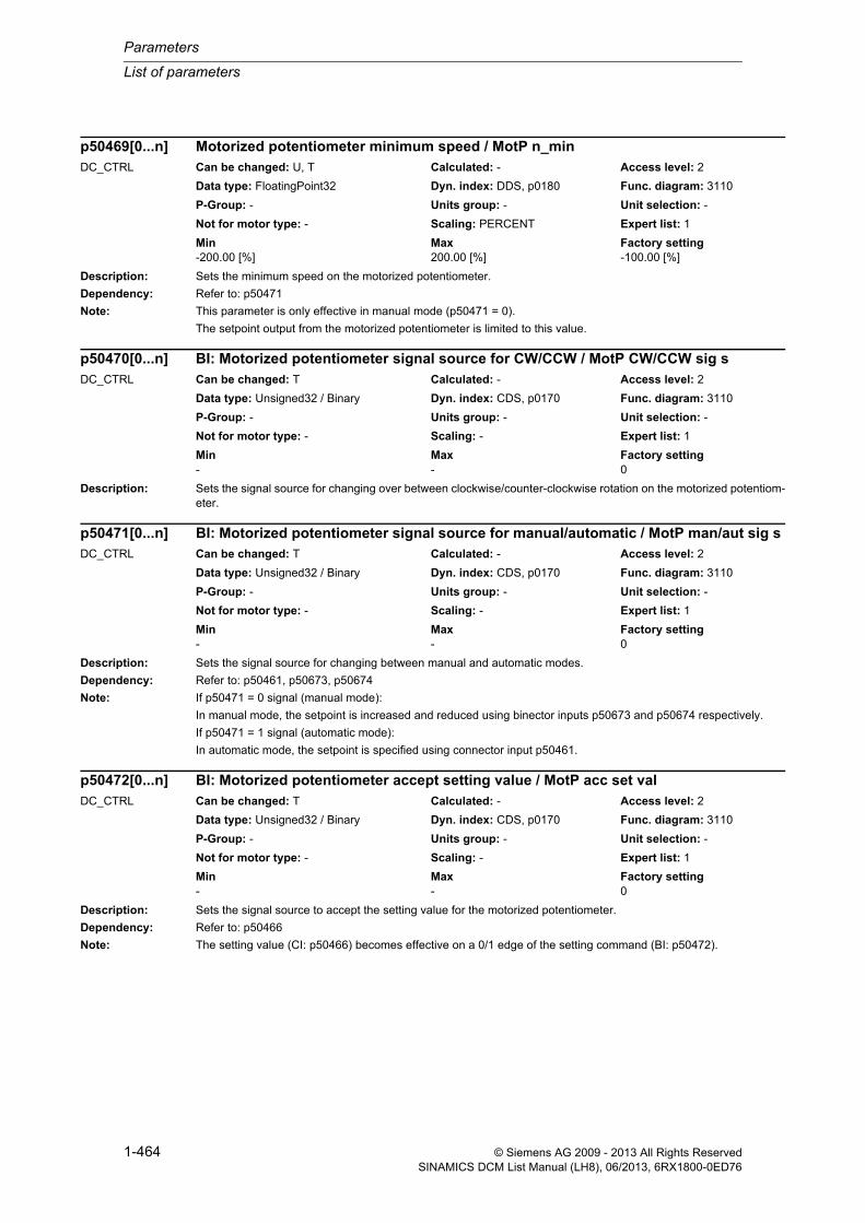
Parameters
List of parameters
1-464 © Siemens AG 2009 - 2013 All Rights ReservedSINAMICS DCM List Manual (LH8), 06/2013, 6RX1800-0ED76
Description: Sets the minimum speed on the motorized potentiometer.
Dependency: Refer to: p50471
Note: This parameter is only effective in manual mode (p50471 = 0).
The setpoint output from the motorized potentiometer is limited to this value.
Description: Sets the signal source for changing over between clockwise/counter-clockwise rotation on the motorized potentiom-eter.
Description: Sets the signal source for changing between manual and automatic modes.
Dependency: Refer to: p50461, p50673, p50674
Note: If p50471 = 0 signal (manual mode):
In manual mode, the setpoint is increased and reduced using binector inputs p50673 and p50674 respectively.
If p50471 = 1 signal (automatic mode):
In automatic mode, the setpoint is specified using connector input p50461.
Description: Sets the signal source to accept the setting value for the motorized potentiometer.
Dependency: Refer to: p50466
Note: The setting value (CI: p50466) becomes effective on a 0/1 edge of the setting command (BI: p50472).
p50469[0...n] Motorized potentiometer minimum speed / MotP n_minDC_CTRL Can be changed: U, T Calculated: - Access level: 2
Data type: FloatingPoint32 Dyn. index: DDS, p0180 Func. diagram: 3110
P-Group: - Units group: - Unit selection: -
Not for motor type: - Scaling: PERCENT Expert list: 1
Min Max Factory setting -200.00 [%] 200.00 [%] -100.00 [%]
p50470[0...n] BI: Motorized potentiometer signal source for CW/CCW / MotP CW/CCW sig sDC_CTRL Can be changed: T Calculated: - Access level: 2
Data type: Unsigned32 / Binary Dyn. index: CDS, p0170 Func. diagram: 3110
P-Group: - Units group: - Unit selection: -
Not for motor type: - Scaling: - Expert list: 1
Min Max Factory setting - - 0
p50471[0...n] BI: Motorized potentiometer signal source for manual/automatic / MotP man/aut sig sDC_CTRL Can be changed: T Calculated: - Access level: 2
Data type: Unsigned32 / Binary Dyn. index: CDS, p0170 Func. diagram: 3110
P-Group: - Units group: - Unit selection: -
Not for motor type: - Scaling: - Expert list: 1
Min Max Factory setting - - 0
p50472[0...n] BI: Motorized potentiometer accept setting value / MotP acc set valDC_CTRL Can be changed: T Calculated: - Access level: 2
Data type: Unsigned32 / Binary Dyn. index: CDS, p0170 Func. diagram: 3110
P-Group: - Units group: - Unit selection: -
Not for motor type: - Scaling: - Expert list: 1
Min Max Factory setting - - 0
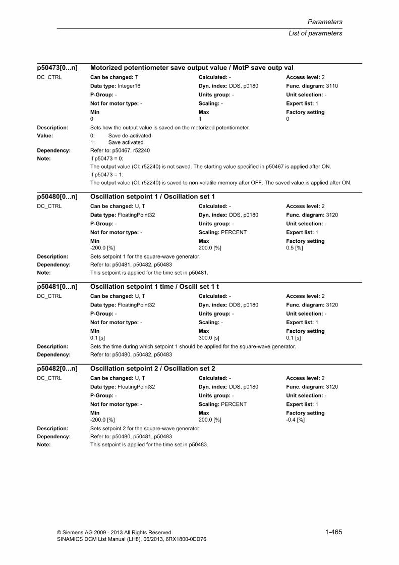
List of parameters
Parameters
1-465© Siemens AG 2009 - 2013 All Rights ReservedSINAMICS DCM List Manual (LH8), 06/2013, 6RX1800-0ED76
Description: Sets how the output value is saved on the motorized potentiometer.
Value: 0: Save de-activated1: Save activated
Dependency: Refer to: p50467, r52240
Note: If p50473 = 0:
The output value (CI: r52240) is not saved. The starting value specified in p50467 is applied after ON.
If p50473 = 1:
The output value (CI: r52240) is saved to non-volatile memory after OFF. The saved value is applied after ON.
Description: Sets setpoint 1 for the square-wave generator.
Dependency: Refer to: p50481, p50482, p50483
Note: This setpoint is applied for the time set in p50481.
Description: Sets the time during which setpoint 1 should be applied for the square-wave generator.
Dependency: Refer to: p50480, p50482, p50483
Description: Sets setpoint 2 for the square-wave generator.
Dependency: Refer to: p50480, p50481, p50483
Note: This setpoint is applied for the time set in p50483.
p50473[0...n] Motorized potentiometer save output value / MotP save outp valDC_CTRL Can be changed: T Calculated: - Access level: 2
Data type: Integer16 Dyn. index: DDS, p0180 Func. diagram: 3110
P-Group: - Units group: - Unit selection: -
Not for motor type: - Scaling: - Expert list: 1
Min Max Factory setting 0 1 0
p50480[0...n] Oscillation setpoint 1 / Oscillation set 1DC_CTRL Can be changed: U, T Calculated: - Access level: 2
Data type: FloatingPoint32 Dyn. index: DDS, p0180 Func. diagram: 3120
P-Group: - Units group: - Unit selection: -
Not for motor type: - Scaling: PERCENT Expert list: 1
Min Max Factory setting -200.0 [%] 200.0 [%] 0.5 [%]
p50481[0...n] Oscillation setpoint 1 time / Oscill set 1 tDC_CTRL Can be changed: U, T Calculated: - Access level: 2
Data type: FloatingPoint32 Dyn. index: DDS, p0180 Func. diagram: 3120
P-Group: - Units group: - Unit selection: -
Not for motor type: - Scaling: - Expert list: 1
Min Max Factory setting 0.1 [s] 300.0 [s] 0.1 [s]
p50482[0...n] Oscillation setpoint 2 / Oscillation set 2DC_CTRL Can be changed: U, T Calculated: - Access level: 2
Data type: FloatingPoint32 Dyn. index: DDS, p0180 Func. diagram: 3120
P-Group: - Units group: - Unit selection: -
Not for motor type: - Scaling: PERCENT Expert list: 1
Min Max Factory setting -200.0 [%] 200.0 [%] -0.4 [%]
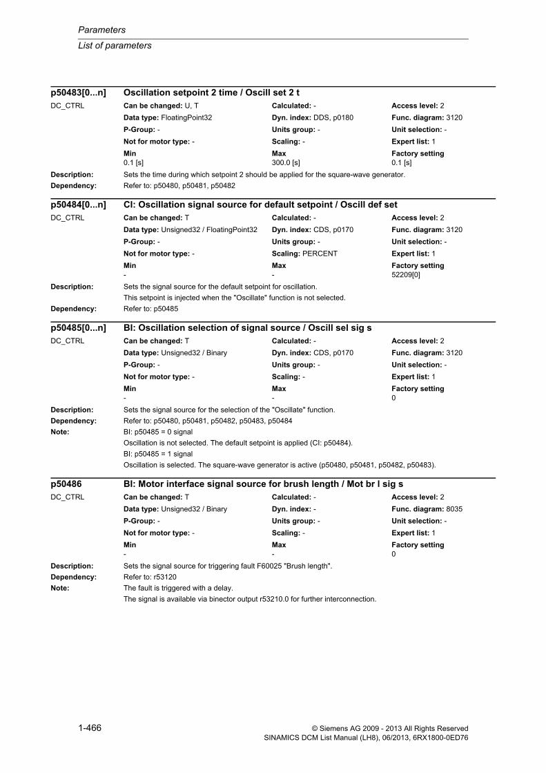
Parameters
List of parameters
1-466 © Siemens AG 2009 - 2013 All Rights ReservedSINAMICS DCM List Manual (LH8), 06/2013, 6RX1800-0ED76
Description: Sets the time during which setpoint 2 should be applied for the square-wave generator.
Dependency: Refer to: p50480, p50481, p50482
Description: Sets the signal source for the default setpoint for oscillation.
This setpoint is injected when the "Oscillate" function is not selected.
Dependency: Refer to: p50485
Description: Sets the signal source for the selection of the "Oscillate" function.
Dependency: Refer to: p50480, p50481, p50482, p50483, p50484
Note: BI: p50485 = 0 signal
Oscillation is not selected. The default setpoint is applied (CI: p50484).
BI: p50485 = 1 signal
Oscillation is selected. The square-wave generator is active (p50480, p50481, p50482, p50483).
Description: Sets the signal source for triggering fault F60025 "Brush length".
Dependency: Refer to: r53120
Note: The fault is triggered with a delay.
The signal is available via binector output r53210.0 for further interconnection.
p50483[0...n] Oscillation setpoint 2 time / Oscill set 2 tDC_CTRL Can be changed: U, T Calculated: - Access level: 2
Data type: FloatingPoint32 Dyn. index: DDS, p0180 Func. diagram: 3120
P-Group: - Units group: - Unit selection: -
Not for motor type: - Scaling: - Expert list: 1
Min Max Factory setting 0.1 [s] 300.0 [s] 0.1 [s]
p50484[0...n] CI: Oscillation signal source for default setpoint / Oscill def setDC_CTRL Can be changed: T Calculated: - Access level: 2
Data type: Unsigned32 / FloatingPoint32 Dyn. index: CDS, p0170 Func. diagram: 3120
P-Group: - Units group: - Unit selection: -
Not for motor type: - Scaling: PERCENT Expert list: 1
Min Max Factory setting - - 52209[0]
p50485[0...n] BI: Oscillation selection of signal source / Oscill sel sig sDC_CTRL Can be changed: T Calculated: - Access level: 2
Data type: Unsigned32 / Binary Dyn. index: CDS, p0170 Func. diagram: 3120
P-Group: - Units group: - Unit selection: -
Not for motor type: - Scaling: - Expert list: 1
Min Max Factory setting - - 0
p50486 BI: Motor interface signal source for brush length / Mot br l sig sDC_CTRL Can be changed: T Calculated: - Access level: 2
Data type: Unsigned32 / Binary Dyn. index: - Func. diagram: 8035
P-Group: - Units group: - Unit selection: -
Not for motor type: - Scaling: - Expert list: 1
Min Max Factory setting - - 0

List of parameters
Parameters
1-467© Siemens AG 2009 - 2013 All Rights ReservedSINAMICS DCM List Manual (LH8), 06/2013, 6RX1800-0ED76
Description: Sets the signal source for triggering fault F60026 "Bearing condition".
Dependency: Refer to: r53120
Note: The fault is triggered with a delay.
The signal is available via binector output r53120.1 for further interconnection.
Description: Sets the signal source for triggering fault F60027 "Motor fan".
Dependency: Refer to: r53120
Note: The fault is triggered with a delay.
The signal is available via binector output r53210.0 for further interconnection.
Description: Sets the signal source for triggering fault F60028 "Motor temperature".
Dependency: Refer to: r53120
Note: The fault is triggered with a delay.
The signal is available via binector output r53210.3 for further interconnection.
Description: Sets the temperature sensor for monitoring the motor temperature.
Value: 0: No sensor1: KTY842: PTC thermistor R_rated 6003: PTC thermistor R_rated 12004: PTC thermistor R_rated 13305: PTC thermistor R_rated 26606: PT1007: NTC thermistor K2278: PT1000
p50487 BI: Motor interface signal source for bearing condition / Mot brg cond sig sDC_CTRL Can be changed: T Calculated: - Access level: 2
Data type: Unsigned32 / Binary Dyn. index: - Func. diagram: 8035
P-Group: - Units group: - Unit selection: -
Not for motor type: - Scaling: - Expert list: 1
Min Max Factory setting - - 0
p50488 BI: Motor interface signal source for motor fan / Mot mot fan sig sDC_CTRL Can be changed: T Calculated: - Access level: 2
Data type: Unsigned32 / Binary Dyn. index: - Func. diagram: 8035
P-Group: - Units group: - Unit selection: -
Not for motor type: - Scaling: - Expert list: 1
Min Max Factory setting - - 0
p50489 BI: Motor interface signal source for motor temperature / Mot mot temp sig sDC_CTRL Can be changed: T Calculated: - Access level: 2
Data type: Unsigned32 / Binary Dyn. index: - Func. diagram: 8035
P-Group: - Units group: - Unit selection: -
Not for motor type: - Scaling: - Expert list: 1
Min Max Factory setting - - 0
p50490 Motor interface temperature sensor / Mot temp sensorDC_CTRL Can be changed: T Calculated: - Access level: 2
Data type: Integer16 Dyn. index: - Func. diagram: 8030
P-Group: - Units group: - Unit selection: -
Not for motor type: - Scaling: - Expert list: 1
Min Max Factory setting 0 8 0

Parameters
List of parameters
1-468 © Siemens AG 2009 - 2013 All Rights ReservedSINAMICS DCM List Manual (LH8), 06/2013, 6RX1800-0ED76
Dependency: Refer to: r50012, r52051
Note: Comments regarding PTC thermistors:
- PTC thermistors according to DIN 44081 / 44082 with the specified R for the rated response temperature.
- For Siemens motors, PTC thermistors with 1330 Ohm are used.
- Parameters p50491 and p50492 (alarm and switch-off temperature) are ineffective. The alarm and switch-off tem-peratures are defined by the PTC thermistor type being used.
Comments on NTC thermistor K227:
The evaluation electronics on the CUD only allow resistance values of less than approx. 2 kOhm to be measured. As a consequence, only temperatures greater than approx. 90 °C can be measured when using these temperature sensors. For lower temperatures, the lowest possible value (approx. 90 °C) is displayed.
Description: Sets the alarm threshold for monitoring the motor temperature.
Dependency: The parameter is only valid for the following temperature sensors with a continuous characteristic:
- KTY84 (p50490 = 1)
- PT100 (p50490 = 6)
- NTC thermistor K227 (p50490 = 7)
- PT1000 (p50490 = 8)
Refer to: p50490, p50492, r52051
Description: Sets the fault threshold for monitoring the motor temperature.
Dependency: The parameter is only valid for the following temperature sensors with a continuous characteristic:
- KTY84 (p50490 = 1)
- PT100 (p50490 = 6)
- NTC thermistor K227 (p50490 = 7)
- PT1000 (p50490 = 8)
Refer to: p50490, p50491, r52051
Description: Sets the signal source for the torque setpoint in slave mode.
Dependency: Refer to: p50503
p50491[0...n] Motor interface alarm threshold for temperature monitoring / Mot_temp al thrDC_CTRL Can be changed: U, T Calculated: - Access level: 2
Data type: FloatingPoint32 Dyn. index: DDS, p0180 Func. diagram: 8030
P-Group: - Units group: - Unit selection: -
Not for motor type: - Scaling: - Expert list: 1
Min Max Factory setting 0 [°C] 200 [°C] 0 [°C]
p50492[0...n] Motor interface fault threshold for temperature monitoring / Mot_temp flt thrDC_CTRL Can be changed: U, T Calculated: - Access level: 2
Data type: FloatingPoint32 Dyn. index: DDS, p0180 Func. diagram: 8030
P-Group: - Units group: - Unit selection: -
Not for motor type: - Scaling: - Expert list: 1
Min Max Factory setting 0 [°C] 200 [°C] 0 [°C]
p50500[0...n] CI: Torque limiting signal source for t_set in slave mode / T_set s mode sig sDC_CTRL Can be changed: T Calculated: - Access level: 2
Data type: Unsigned32 / FloatingPoint32 Dyn. index: CDS, p0170 Func. diagram: 6830
P-Group: - Units group: - Unit selection: -
Not for motor type: - Scaling: PERCENT Expert list: 1
Min Max Factory setting - - 52170[0]

List of parameters
Parameters
1-469© Siemens AG 2009 - 2013 All Rights ReservedSINAMICS DCM List Manual (LH8), 06/2013, 6RX1800-0ED76
Description: Sets the signal source for the torque additional setpoint in torque limiting.
The value is injected in addition to friction and moment of inertia compensation.
Description: Sets the signal source for the additional setpoint of the speed controller.
This value is added to the speed controller's output value.
Description: Sets the factor for the torque setpoint in slave mode.
Dependency: Refer to: p50500
Description: Sets the signal source for the speed actual value (n_act) on the speed limiting controller.
Description: Sets the signal source for the positive torque limit on the speed limiting controller.
Dependency: Refer to: r52136
Note: This parameter specifies which parameter is to be injected as the limit value for torque limiting 1 (r52136).
p50501[0...n] CI: Torque limiting signal source for torque additional setpoint / T_lim add s sig sDC_CTRL Can be changed: T Calculated: - Access level: 2
Data type: Unsigned32 / FloatingPoint32 Dyn. index: CDS, p0170 Func. diagram: 6830
P-Group: - Units group: - Unit selection: -
Not for motor type: - Scaling: PERCENT Expert list: 1
Min Max Factory setting - - 0
p50502 CI: Speed controller additional setpoint signal source / Add set sig sDC_CTRL Can be changed: T Calculated: - Access level: 2
Data type: Unsigned32 / FloatingPoint32 Dyn. index: - Func. diagram: 6815
P-Group: - Units group: - Unit selection: -
Not for motor type: - Scaling: PERCENT Expert list: 1
Min Max Factory setting - - 0
p50503[0...n] Torque limiting t_set factor in slave mode / T_set fact sl modeDC_CTRL Can be changed: U, T Calculated: - Access level: 2
Data type: FloatingPoint32 Dyn. index: DDS, p0180 Func. diagram: 6830
P-Group: - Units group: - Unit selection: -
Not for motor type: - Scaling: PERCENT Expert list: 1
Min Max Factory setting -300.00 [%] 300.00 [%] 100.00 [%]
p50509 CI: Speed limiting controller signal source for speed actual value / n_lim n_act sig sDC_CTRL Can be changed: T Calculated: - Access level: 2
Data type: Unsigned32 / FloatingPoint32 Dyn. index: - Func. diagram: 6835
P-Group: - Units group: - Unit selection: -
Not for motor type: - Scaling: PERCENT Expert list: 1
Min Max Factory setting - - 52167[0]
p50510 CI: Speed limiting controller signal source for pos torque limit / T lim pos sig sDC_CTRL Can be changed: T Calculated: - Access level: 2
Data type: Unsigned32 / FloatingPoint32 Dyn. index: - Func. diagram: 6835
P-Group: - Units group: - Unit selection: -
Not for motor type: - Scaling: PERCENT Expert list: 1
Min Max Factory setting - - 52002[0]

Parameters
List of parameters
1-470 © Siemens AG 2009 - 2013 All Rights ReservedSINAMICS DCM List Manual (LH8), 06/2013, 6RX1800-0ED76
Description: Sets the signal source for the negative torque limit on the speed limiting controller.
Dependency: Refer to: r52137
Note: This parameter specifies which parameter is to be injected as the limit value for torque limiting 2 (r52137).
Description: Sets the maximum speed for the positive direction of rotation on the speed limiting controller.
Description: Sets the maximum speed for the negative direction of rotation on the speed limiting controller.
Description: Sets the P gain on the speed limiting controller.
Description: Sets the signal sources for friction compensation.
Index: [0] = Signed[1] = Absolute
Note: The signals in p50519[0] and p50519[1] are summed and applied to the friction compensation input.
p50511 CI: Speed limiting controller signal source for neg torque limit / T lim neg sig sDC_CTRL Can be changed: T Calculated: - Access level: 2
Data type: Unsigned32 / FloatingPoint32 Dyn. index: - Func. diagram: 6835
P-Group: - Units group: - Unit selection: -
Not for motor type: - Scaling: PERCENT Expert list: 1
Min Max Factory setting - - 52004[0]
p50512[0...n] Speed limiting controller max speed pos direction of rotation / n_max pos dir rotDC_CTRL Can be changed: U, T Calculated: - Access level: 2
Data type: FloatingPoint32 Dyn. index: DDS, p0180 Func. diagram: 6835
P-Group: - Units group: - Unit selection: -
Not for motor type: - Scaling: PERCENT Expert list: 1
Min Max Factory setting 0.0 [%] 200.0 [%] 105.0 [%]
p50513[0...n] Speed limiting controller max speed neg direction of rotation / n_max neg dirDC_CTRL Can be changed: U, T Calculated: - Access level: 2
Data type: FloatingPoint32 Dyn. index: DDS, p0180 Func. diagram: 6835
P-Group: - Units group: - Unit selection: -
Not for motor type: - Scaling: PERCENT Expert list: 1
Min Max Factory setting -200.0 [%] 0.0 [%] -105.0 [%]
p50515[0...n] Speed limiting controller P gain / n_lim KpDC_CTRL Can be changed: U, T Calculated: - Access level: 2
Data type: FloatingPoint32 Dyn. index: DDS, p0180 Func. diagram: 6835
P-Group: - Units group: - Unit selection: -
Not for motor type: - Scaling: - Expert list: 1
Min Max Factory setting 0.10 200.00 3.00
p50519[0...1] CI: Input signal for friction compensation / Fric comp inp sigDC_CTRL Can be changed: T Calculated: - Access level: 3
Data type: Unsigned32 / FloatingPoint32 Dyn. index: - Func. diagram: 6820
P-Group: - Units group: - Unit selection: -
Not for motor type: - Scaling: PERCENT Expert list: 1
Min Max Factory setting - - [0] 52179[0]
[1] 0

List of parameters
Parameters
1-471© Siemens AG 2009 - 2013 All Rights ReservedSINAMICS DCM List Manual (LH8), 06/2013, 6RX1800-0ED76
Description: Sets friction compensation at 0 % speed.
Recommend.: In the case of operation in both directions of rotation, this basic value should be set to 0% to prevent the armature current from oscillating.
Note: The basic values are based on the device rated direct current or the device rated torque.
The basic values for friction compensation (p50520 ... p50530) are set automatically during the optimization run for friction compensation (p50051 = 28).
There is linear interpolation between the basic values; here, the friction compensation value takes on the input sig-nal's sign.
Description: Sets friction compensation at 10 % speed.
Description: Sets friction compensation at 20 % speed.
Description: Sets friction compensation at 30 % speed.
Description: Sets friction compensation at 40 % speed.
p50520[0...n] Friction compensation 0 % speed / Fric comp n 0%DC_CTRL Can be changed: U, T Calculated: - Access level: 2
Data type: FloatingPoint32 Dyn. index: DDS, p0180 Func. diagram: 6820
P-Group: - Units group: - Unit selection: -
Not for motor type: - Scaling: PERCENT Expert list: 1
Min Max Factory setting 0.0 [%] 100.0 [%] 0.0 [%]
p50521[0...n] Friction compensation 10 % speed / Fric comp n 10%DC_CTRL Can be changed: U, T Calculated: - Access level: 2
Data type: FloatingPoint32 Dyn. index: DDS, p0180 Func. diagram: 6820
P-Group: - Units group: - Unit selection: -
Not for motor type: - Scaling: PERCENT Expert list: 1
Min Max Factory setting 0.0 [%] 100.0 [%] 0.0 [%]
p50522[0...n] Friction compensation 20 % speed / Fric comp n 20%DC_CTRL Can be changed: U, T Calculated: - Access level: 2
Data type: FloatingPoint32 Dyn. index: DDS, p0180 Func. diagram: 6820
P-Group: - Units group: - Unit selection: -
Not for motor type: - Scaling: PERCENT Expert list: 1
Min Max Factory setting 0.0 [%] 100.0 [%] 0.0 [%]
p50523[0...n] Friction compensation 30 % speed / Fric comp n 30%DC_CTRL Can be changed: U, T Calculated: - Access level: 2
Data type: FloatingPoint32 Dyn. index: DDS, p0180 Func. diagram: 6820
P-Group: - Units group: - Unit selection: -
Not for motor type: - Scaling: PERCENT Expert list: 1
Min Max Factory setting 0.0 [%] 100.0 [%] 0.0 [%]
p50524[0...n] Friction compensation 40 % speed / Fric comp n 40%DC_CTRL Can be changed: U, T Calculated: - Access level: 2
Data type: FloatingPoint32 Dyn. index: DDS, p0180 Func. diagram: 6820
P-Group: - Units group: - Unit selection: -
Not for motor type: - Scaling: PERCENT Expert list: 1
Min Max Factory setting 0.0 [%] 100.0 [%] 0.0 [%]
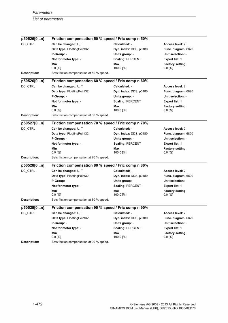
Parameters
List of parameters
1-472 © Siemens AG 2009 - 2013 All Rights ReservedSINAMICS DCM List Manual (LH8), 06/2013, 6RX1800-0ED76
Description: Sets friction compensation at 50 % speed.
Description: Sets friction compensation at 60 % speed.
Description: Sets friction compensation at 70 % speed.
Description: Sets friction compensation at 80 % speed.
Description: Sets friction compensation at 90 % speed.
p50525[0...n] Friction compensation 50 % speed / Fric comp n 50%DC_CTRL Can be changed: U, T Calculated: - Access level: 2
Data type: FloatingPoint32 Dyn. index: DDS, p0180 Func. diagram: 6820
P-Group: - Units group: - Unit selection: -
Not for motor type: - Scaling: PERCENT Expert list: 1
Min Max Factory setting 0.0 [%] 100.0 [%] 0.0 [%]
p50526[0...n] Friction compensation 60 % speed / Fric comp n 60%DC_CTRL Can be changed: U, T Calculated: - Access level: 2
Data type: FloatingPoint32 Dyn. index: DDS, p0180 Func. diagram: 6820
P-Group: - Units group: - Unit selection: -
Not for motor type: - Scaling: PERCENT Expert list: 1
Min Max Factory setting 0.0 [%] 100.0 [%] 0.0 [%]
p50527[0...n] Friction compensation 70 % speed / Fric comp n 70%DC_CTRL Can be changed: U, T Calculated: - Access level: 2
Data type: FloatingPoint32 Dyn. index: DDS, p0180 Func. diagram: 6820
P-Group: - Units group: - Unit selection: -
Not for motor type: - Scaling: PERCENT Expert list: 1
Min Max Factory setting 0.0 [%] 100.0 [%] 0.0 [%]
p50528[0...n] Friction compensation 80 % speed / Fric comp n 80%DC_CTRL Can be changed: U, T Calculated: - Access level: 2
Data type: FloatingPoint32 Dyn. index: DDS, p0180 Func. diagram: 6820
P-Group: - Units group: - Unit selection: -
Not for motor type: - Scaling: PERCENT Expert list: 1
Min Max Factory setting 0.0 [%] 100.0 [%] 0.0 [%]
p50529[0...n] Friction compensation 90 % speed / Fric comp n 90%DC_CTRL Can be changed: U, T Calculated: - Access level: 2
Data type: FloatingPoint32 Dyn. index: DDS, p0180 Func. diagram: 6820
P-Group: - Units group: - Unit selection: -
Not for motor type: - Scaling: PERCENT Expert list: 1
Min Max Factory setting 0.0 [%] 100.0 [%] 0.0 [%]

List of parameters
Parameters
1-473© Siemens AG 2009 - 2013 All Rights ReservedSINAMICS DCM List Manual (LH8), 06/2013, 6RX1800-0ED76
Description: Sets friction compensation at 100% speed.
Note: This basic value is also effective at speeds > 100%.
Description: Sets the acceleration time on the speed controller.
Dependency: Refer to: r52150, r52174
Note: The acceleration time is the time which would be needed to accelerate the drive from 0 to 100% of the maximum speed at 100% device rated current (with no friction present). It is a measure of the moment of inertia at the motor shaft.
The acceleration time is set automatically during the optimization run for the speed controller (p50051 = 26).
Description: Sets the factor for the acceleration on the speed controller, which is dependent upon the difference between the setpoint and the actual value.
In the case of the "Acceleration dependent upon setpoint/actual value difference" function, only the proportion of the speed controller's setpoint/actual value difference which has an absolute value in excess of the threshold (p50543) is switched through.
Dependency: Refer to: p50543
Description: Sets the dt for the output of dy/dt in r52191.
The change in the ramp-function generator's output variable (p52190) in relation to the time set in p50542 is output in r52191.
Dependency: Refer to: p50330, r52191
p50530[0...n] Friction compensation 100% speed / Fric comp n 100%DC_CTRL Can be changed: U, T Calculated: - Access level: 2
Data type: FloatingPoint32 Dyn. index: DDS, p0180 Func. diagram: 6820
P-Group: - Units group: - Unit selection: -
Not for motor type: - Scaling: PERCENT Expert list: 1
Min Max Factory setting 0.0 [%] 100.0 [%] 0.0 [%]
p50540[0...n] Speed controller acceleration time / n_ctr t_accelDC_CTRL Can be changed: U, T Calculated: - Access level: 2
Data type: FloatingPoint32 Dyn. index: DDS, p0180 Func. diagram: 6820
P-Group: - Units group: - Unit selection: -
Not for motor type: - Scaling: - Expert list: 1
Min Max Factory setting 0.00 [s] 1000.00 [s] 0.01 [s]
p50541[0...3] Speed controller setpoint/actual value difference factor / Set/act dif factDC_CTRL Can be changed: U, T Calculated: - Access level: 2
Data type: FloatingPoint32 Dyn. index: - Func. diagram: 6820
P-Group: - Units group: - Unit selection: -
Not for motor type: - Scaling: - Expert list: 1
Min Max Factory setting 0.00 650.00 0.00
p50542[0...n] RFG dy/dt time difference / RFG dy/dt t_difDC_CTRL Can be changed: U, T Calculated: - Access level: 2
Data type: FloatingPoint32 Dyn. index: DDS, p0180 Func. diagram: 3152
P-Group: - Units group: - Unit selection: -
Not for motor type: - Scaling: - Expert list: 1
Min Max Factory setting 0.00 [s] 1000.00 [s] 0.01 [s]

Parameters
List of parameters
1-474 © Siemens AG 2009 - 2013 All Rights ReservedSINAMICS DCM List Manual (LH8), 06/2013, 6RX1800-0ED76
Note: Example:
A ramp-up time of 5 s is set on the ramp-function generator; in other words, a complete ramp-up from y = 0% to 100% will take 5 s.
A time difference dt of 2 s is set in p50542. This results in a dy/dt of 40% at r52191, since the set dt of 2s produces a dy of (2 s / 5 s) * 100% = 40%.
Description: Sets the threshold for acceleration dependent upon the setpoint/actual value difference.
In the case of the "Acceleration dependent upon setpoint/actual value difference" function, only the proportion of the speed controller's setpoint/actual value difference which has an absolute value in excess of the threshold (p50543) is switched through.
Dependency: Refer to: p50541
Description: Sets the smoothing time constant for the acceleration value for moment of inertia compensation.
Dependency: Refer to: p50619
Description: Sets the y coordinate for pair of values 1 for adaptation of the P gain (Kp).
Note: This P gain (Kp) is effective up to x coordinate 1 (p50556).
The adaptation of the P gain (Kp) is defined using 2 pairs of values.
Pair of values 1:
p50556/p50550 (x/y coordinate)
Pair of values 2:
p50559/p50225 (x/y coordinate)
Description: Sets the y coordinate for pair of values 1 for adaptation of the integral time (Tn).
p50543[0...n] Speed controller setpoint/actual value difference threshold / Set/act dif threshDC_CTRL Can be changed: U, T Calculated: - Access level: 2
Data type: FloatingPoint32 Dyn. index: DDS, p0180 Func. diagram: 6820
P-Group: - Units group: - Unit selection: -
Not for motor type: - Scaling: PERCENT Expert list: 1
Min Max Factory setting 0.00 [%] 100.00 [%] 0.00 [%]
p50546[0...n] Smoothing time constant for inertia compensation / Comp inert TDC_CTRL Can be changed: U, T Calculated: - Access level: 2
Data type: FloatingPoint32 Dyn. index: DDS, p0180 Func. diagram: 6820
P-Group: - Units group: - Unit selection: -
Not for motor type: - Scaling: - Expert list: 1
Min Max Factory setting 0 [ms] 10000 [ms] 0 [ms]
p50550[0...n] Speed controller adaptation Kp y coordinate 1 / Adapt Kp y1DC_CTRL Can be changed: U, T Calculated: - Access level: 2
Data type: FloatingPoint32 Dyn. index: DDS, p0180 Func. diagram: 6805
P-Group: - Units group: - Unit selection: -
Not for motor type: - Scaling: - Expert list: 1
Min Max Factory setting 0.10 2000.00 3.00
p50551[0...n] Speed controller adaptation Tn y coordinate 1 / Adapt Tn y1DC_CTRL Can be changed: U, T Calculated: - Access level: 2
Data type: FloatingPoint32 Dyn. index: DDS, p0180 Func. diagram: 6805
P-Group: - Units group: - Unit selection: -
Not for motor type: - Scaling: - Expert list: 1
Min Max Factory setting 0.010 [s] 10.000 [s] 0.650 [s]

List of parameters
Parameters
1-475© Siemens AG 2009 - 2013 All Rights ReservedSINAMICS DCM List Manual (LH8), 06/2013, 6RX1800-0ED76
Note: This integral time (Tn) is effective up to x coordinate 1 (p50557).
The adaptation of the integral time (Tn) is defined using 2 pairs of values.
Pair of values 1:
p50557/p50551 (x/y coordinate)
Pair of values 2:
p50560/p50226 (x/y coordinate)
Description: Sets the y coordinate for pair of values 1 for adaptation of the droop.
Notice: - For the droop, generally values up to 10 % are practical (p50552 = 0.000 ... 0.100). Under certain circumstances, higher values can result in an unstable response of the speed controller.
- The droop is entered as absolute factor without any dimensions and it is especially important to note that it is not a percentage.
Example:
Set droop = 5 % --> p50552 = 0.05
Note: This droop is effective up to x coordinate 1 (p50558).
The adaptation of the droop is defined using 2 pairs of values.
Pair of values 1:
p50558/p50552 (x/y coordinate)
Pair of values 2:
p50561/p50227 (x/y coordinate)
Description: Sets the signal source for the P gain (Kp) on the speed controller.
Description: Sets the signal source for the integral time (Tn) on the speed controller.
p50552[0...3] Speed controller adaptation droop y coordinate 1 / Adapt droop y1DC_CTRL Can be changed: U, T Calculated: - Access level: 2
Data type: FloatingPoint32 Dyn. index: - Func. diagram: 6805
P-Group: - Units group: - Unit selection: -
Not for motor type: - Scaling: - Expert list: 1
Min Max Factory setting 0.000 10.000 0.000
p50553[0...n] CI: Speed controller adaptation Kp signal source / Adapt Kp sig sDC_CTRL Can be changed: T Calculated: - Access level: 2
Data type: Unsigned32 / FloatingPoint32 Dyn. index: CDS, p0170 Func. diagram: 6805
P-Group: - Units group: - Unit selection: -
Not for motor type: - Scaling: PERCENT Expert list: 1
Min Max Factory setting - - 0
p50554[0...n] CI: Speed controller adaptation Tn signal source / Adapt Tn sig sDC_CTRL Can be changed: T Calculated: - Access level: 2
Data type: Unsigned32 / FloatingPoint32 Dyn. index: CDS, p0170 Func. diagram: 6805
P-Group: - Units group: - Unit selection: -
Not for motor type: - Scaling: PERCENT Expert list: 1
Min Max Factory setting - - 0
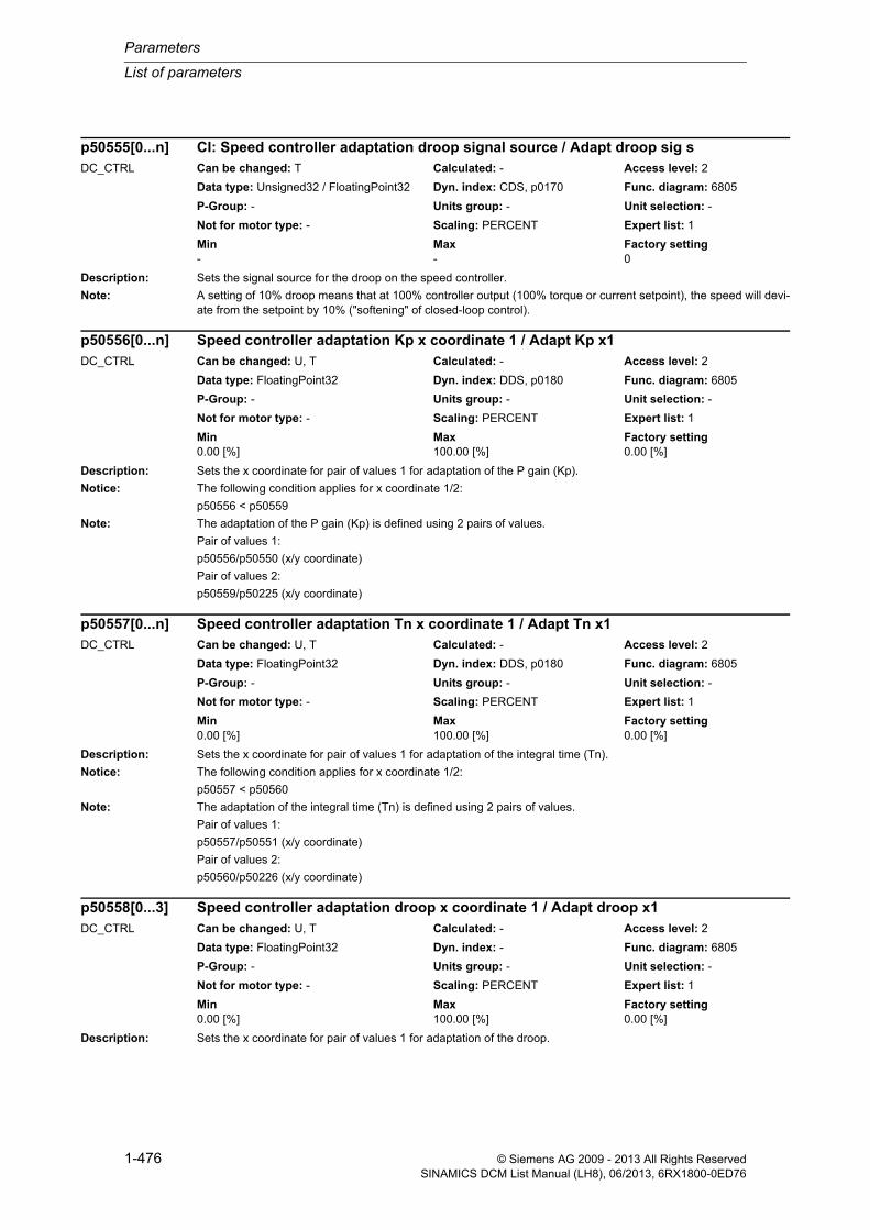
Parameters
List of parameters
1-476 © Siemens AG 2009 - 2013 All Rights ReservedSINAMICS DCM List Manual (LH8), 06/2013, 6RX1800-0ED76
Description: Sets the signal source for the droop on the speed controller.
Note: A setting of 10% droop means that at 100% controller output (100% torque or current setpoint), the speed will devi-ate from the setpoint by 10% ("softening" of closed-loop control).
Description: Sets the x coordinate for pair of values 1 for adaptation of the P gain (Kp).
Notice: The following condition applies for x coordinate 1/2:
p50556 < p50559
Note: The adaptation of the P gain (Kp) is defined using 2 pairs of values.
Pair of values 1:
p50556/p50550 (x/y coordinate)
Pair of values 2:
p50559/p50225 (x/y coordinate)
Description: Sets the x coordinate for pair of values 1 for adaptation of the integral time (Tn).
Notice: The following condition applies for x coordinate 1/2:
p50557 < p50560
Note: The adaptation of the integral time (Tn) is defined using 2 pairs of values.
Pair of values 1:
p50557/p50551 (x/y coordinate)
Pair of values 2:
p50560/p50226 (x/y coordinate)
Description: Sets the x coordinate for pair of values 1 for adaptation of the droop.
p50555[0...n] CI: Speed controller adaptation droop signal source / Adapt droop sig sDC_CTRL Can be changed: T Calculated: - Access level: 2
Data type: Unsigned32 / FloatingPoint32 Dyn. index: CDS, p0170 Func. diagram: 6805
P-Group: - Units group: - Unit selection: -
Not for motor type: - Scaling: PERCENT Expert list: 1
Min Max Factory setting - - 0
p50556[0...n] Speed controller adaptation Kp x coordinate 1 / Adapt Kp x1DC_CTRL Can be changed: U, T Calculated: - Access level: 2
Data type: FloatingPoint32 Dyn. index: DDS, p0180 Func. diagram: 6805
P-Group: - Units group: - Unit selection: -
Not for motor type: - Scaling: PERCENT Expert list: 1
Min Max Factory setting 0.00 [%] 100.00 [%] 0.00 [%]
p50557[0...n] Speed controller adaptation Tn x coordinate 1 / Adapt Tn x1DC_CTRL Can be changed: U, T Calculated: - Access level: 2
Data type: FloatingPoint32 Dyn. index: DDS, p0180 Func. diagram: 6805
P-Group: - Units group: - Unit selection: -
Not for motor type: - Scaling: PERCENT Expert list: 1
Min Max Factory setting 0.00 [%] 100.00 [%] 0.00 [%]
p50558[0...3] Speed controller adaptation droop x coordinate 1 / Adapt droop x1DC_CTRL Can be changed: U, T Calculated: - Access level: 2
Data type: FloatingPoint32 Dyn. index: - Func. diagram: 6805
P-Group: - Units group: - Unit selection: -
Not for motor type: - Scaling: PERCENT Expert list: 1
Min Max Factory setting 0.00 [%] 100.00 [%] 0.00 [%]

List of parameters
Parameters
1-477© Siemens AG 2009 - 2013 All Rights ReservedSINAMICS DCM List Manual (LH8), 06/2013, 6RX1800-0ED76
Notice: The following condition applies for x coordinate 1/2:
p50558 < p50561
Note: The adaptation of the droop is defined using 2 pairs of values.
Pair of values 1:
p50558/p50552 (x/y coordinate)
Pair of values 2:
p50561/p50227 (x/y coordinate)
Description: Sets the x coordinate for pair of values 2 for adaptation of the P gain (Kp).
Notice: The following condition applies for x coordinate 1/2:
p50556 < p50559
Note: The adaptation of the P gain (Kp) is defined using 2 pairs of values.
Pair of values 1:
p50556/p50550 (x/y coordinate)
Pair of values 2:
p50559/p50225 (x/y coordinate)
Description: Sets the x coordinate for pair of values 2 for adaptation of the integral time (Tn).
Notice: The following condition applies for x coordinate 1/2:
p50557 < p50560
Note: The adaptation of the integral time (Tn) is defined using 2 pairs of values.
Pair of values 1:
p50557/p50551 (x/y coordinate)
Pair of values 2:
p50560/p50226 (x/y coordinate)
Description: Sets the x coordinate for pair of values 2 for adaptation of the droop.
Notice: The following condition applies for x coordinate 1/2:
p50558 < p50561
p50559[0...n] Speed controller adaptation Kp x coordinate 2 / Adapt Kp x2DC_CTRL Can be changed: U, T Calculated: - Access level: 2
Data type: FloatingPoint32 Dyn. index: DDS, p0180 Func. diagram: 6805
P-Group: - Units group: - Unit selection: -
Not for motor type: - Scaling: PERCENT Expert list: 1
Min Max Factory setting 0.00 [%] 100.00 [%] 0.00 [%]
p50560[0...n] Speed controller adaptation Tn x coordinate 2 / Adapt Tn x2DC_CTRL Can be changed: U, T Calculated: - Access level: 2
Data type: FloatingPoint32 Dyn. index: DDS, p0180 Func. diagram: 6805
P-Group: - Units group: - Unit selection: -
Not for motor type: - Scaling: PERCENT Expert list: 1
Min Max Factory setting 0.00 [%] 100.00 [%] 0.00 [%]
p50561[0...n] Speed controller adaptation droop x coordinate 2 / Adapt droop x2DC_CTRL Can be changed: U, T Calculated: - Access level: 2
Data type: FloatingPoint32 Dyn. index: DDS, p0180 Func. diagram: 6805
P-Group: - Units group: - Unit selection: -
Not for motor type: - Scaling: PERCENT Expert list: 1
Min Max Factory setting 0.00 [%] 100.00 [%] 0.00 [%]

Parameters
List of parameters
1-478 © Siemens AG 2009 - 2013 All Rights ReservedSINAMICS DCM List Manual (LH8), 06/2013, 6RX1800-0ED76
Note: The adaptation of the droop is defined using 2 pairs of values.
Pair of values 1:
p50558/p50552 (x/y coordinate)
Pair of values 2:
p50561/p50227 (x/y coordinate)
Description: Sets positive limiting for the droop on the speed controller.
Dependency: Refer to: p50563
Description: Sets negative limiting for the droop on the speed controller.
Dependency: Refer to: p50562
Description: Sets the base speed for the frequency response plot for the optimization run "Speed control optimization for drives that are capable of oscillation" (p50051 = 29).
Dependency: Refer to: p50566, p50567
Description: Sets the amplitude for the frequency response plot for the optimization run "Speed control optimization for drives that are capable of oscillation" (p50051 = 29).
p50562[0...n] Speed controller droop positive limiting / Droop pos limDC_CTRL Can be changed: U, T Calculated: - Access level: 2
Data type: FloatingPoint32 Dyn. index: DDS, p0180 Func. diagram: 6805
P-Group: - Units group: - Unit selection: -
Not for motor type: - Scaling: PERCENT Expert list: 1
Min Max Factory setting 0.00 [%] 200.00 [%] 100.00 [%]
p50563[0...n] Speed controller droop negative limiting / Droop neg limDC_CTRL Can be changed: U, T Calculated: - Access level: 2
Data type: FloatingPoint32 Dyn. index: DDS, p0180 Func. diagram: 6805
P-Group: - Units group: - Unit selection: -
Not for motor type: - Scaling: PERCENT Expert list: 1
Min Max Factory setting -200.00 [%] 0.00 [%] -100.00 [%]
p50565 Speed controller optimization frequency response plot base speed / f_plot n_baseDC_CTRL Can be changed: T Calculated: - Access level: 2
Data type: FloatingPoint32 Dyn. index: - Func. diagram: 2660
P-Group: - Units group: - Unit selection: -
Not for motor type: - Scaling: PERCENT Expert list: 1
Min Max Factory setting 1.0 [%] 30.0 [%] 20.0 [%]
p50566 Speed controller optimization frequency response plot amplitude / f_plot amplitudeDC_CTRL Can be changed: T Calculated: - Access level: 2
Data type: FloatingPoint32 Dyn. index: - Func. diagram: 2660
P-Group: - Units group: - Unit selection: -
Not for motor type: - Scaling: PERCENT Expert list: 1
Min Max Factory setting 0.01 [%] 5.00 [%] 1.00 [%]

List of parameters
Parameters
1-479© Siemens AG 2009 - 2013 All Rights ReservedSINAMICS DCM List Manual (LH8), 06/2013, 6RX1800-0ED76
Description: Sets the time for the frequency response plot for the optimization run "Speed control optimization for drives that are capable of oscillation" (p50051 = 29).
In this case, an average is generated over the time set here per measuring frequency.
Note: High values improve the result, however they slow down the measuring time.
For the 3.0 s setting, it takes approximately 9 minutes to plot the frequency response.
Description: Sets the input quantity for armature current controller adaptation.
Value: 0: Ia_act r521171: Ia_set r52119
Dependency: Refer to: p50571, p50572
Description: Setting to activate the adaptation of non-linear inductances for the armature current controller.
Value: 0: Adaptation non-linear L active1: Fixed value 100 % effective
Dependency: Refer to: p50570, p50572, r52350
Description: Setting to activate the intermittent adaptation for the armature current controller.
Value: 0: Intermittent adaptation effective1: Fixed value 100 %
Dependency: Refer to: p50570, p50571, r52350
p50567 Speed controller optimization frequency response plot time / f_plot timeDC_CTRL Can be changed: T Calculated: - Access level: 2
Data type: FloatingPoint32 Dyn. index: - Func. diagram: 2660
P-Group: - Units group: - Unit selection: -
Not for motor type: - Scaling: - Expert list: 1
Min Max Factory setting 0.30 [s] 3.00 [s] 1.00 [s]
p50570[0...n] Adaptation armature current controller changeover input / Adapt Ia chgov inpDC_CTRL Can be changed: U, T Calculated: - Access level: 2
Data type: Integer16 Dyn. index: DDS, p0180 Func. diagram: 6853
P-Group: - Units group: - Unit selection: -
Not for motor type: - Scaling: - Expert list: 1
Min Max Factory setting 0 1 0
p50571[0...n] Adaptation armature current controller non-linear L activation / Adapt N_lin L actDC_CTRL Can be changed: U, T Calculated: - Access level: 2
Data type: Integer16 Dyn. index: DDS, p0180 Func. diagram: 6853
P-Group: - Units group: - Unit selection: -
Not for motor type: - Scaling: - Expert list: 1
Min Max Factory setting 0 1 0
p50572[0...n] Adapt arm curr controller intermittent adapt activation / Adapt Interm ActDC_CTRL Can be changed: U, T Calculated: - Access level: 2
Data type: Integer16 Dyn. index: DDS, p0180 Func. diagram: 6853
P-Group: - Units group: - Unit selection: -
Not for motor type: - Scaling: - Expert list: 1
Min Max Factory setting 0 1 0
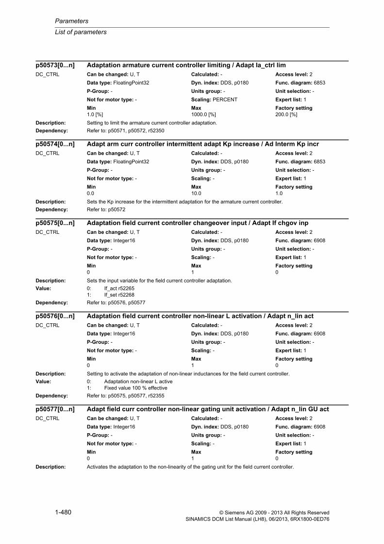
Parameters
List of parameters
1-480 © Siemens AG 2009 - 2013 All Rights ReservedSINAMICS DCM List Manual (LH8), 06/2013, 6RX1800-0ED76
Description: Setting to limit the armature current controller adaptation.
Dependency: Refer to: p50571, p50572, r52350
Description: Sets the Kp increase for the intermittent adaptation for the armature current controller.
Dependency: Refer to: p50572
Description: Sets the input variable for the field current controller adaptation.
Value: 0: If_act r522651: If_set r52268
Dependency: Refer to: p50576, p50577
Description: Setting to activate the adaptation of non-linear inductances for the field current controller.
Value: 0: Adaptation non-linear L active1: Fixed value 100 % effective
Dependency: Refer to: p50575, p50577, r52355
Description: Activates the adaptation to the non-linearity of the gating unit for the field current controller.
p50573[0...n] Adaptation armature current controller limiting / Adapt Ia_ctrl limDC_CTRL Can be changed: U, T Calculated: - Access level: 2
Data type: FloatingPoint32 Dyn. index: DDS, p0180 Func. diagram: 6853
P-Group: - Units group: - Unit selection: -
Not for motor type: - Scaling: PERCENT Expert list: 1
Min Max Factory setting 1.0 [%] 1000.0 [%] 200.0 [%]
p50574[0...n] Adapt arm curr controller intermittent adapt Kp increase / Ad Interm Kp incrDC_CTRL Can be changed: U, T Calculated: - Access level: 2
Data type: FloatingPoint32 Dyn. index: DDS, p0180 Func. diagram: 6853
P-Group: - Units group: - Unit selection: -
Not for motor type: - Scaling: - Expert list: 1
Min Max Factory setting 0.0 10.0 1.0
p50575[0...n] Adaptation field current controller changeover input / Adapt If chgov inpDC_CTRL Can be changed: U, T Calculated: - Access level: 2
Data type: Integer16 Dyn. index: DDS, p0180 Func. diagram: 6908
P-Group: - Units group: - Unit selection: -
Not for motor type: - Scaling: - Expert list: 1
Min Max Factory setting 0 1 0
p50576[0...n] Adaptation field current controller non-linear L activation / Adapt n_lin actDC_CTRL Can be changed: U, T Calculated: - Access level: 2
Data type: Integer16 Dyn. index: DDS, p0180 Func. diagram: 6908
P-Group: - Units group: - Unit selection: -
Not for motor type: - Scaling: - Expert list: 1
Min Max Factory setting 0 1 0
p50577[0...n] Adapt field curr controller non-linear gating unit activation / Adapt n_lin GU actDC_CTRL Can be changed: U, T Calculated: - Access level: 2
Data type: Integer16 Dyn. index: DDS, p0180 Func. diagram: 6908
P-Group: - Units group: - Unit selection: -
Not for motor type: - Scaling: - Expert list: 1
Min Max Factory setting 0 1 0

List of parameters
Parameters
1-481© Siemens AG 2009 - 2013 All Rights ReservedSINAMICS DCM List Manual (LH8), 06/2013, 6RX1800-0ED76
Value: 0: Adaptation gating unit effective1: Fixed value 100 % effective
Dependency: Refer to: p50575, p50576, r52355
Description: Setting to limit the field current controller adaptation.
Dependency: Refer to: p50576, p50577, r52355
Description: Sets the signal source for the direction of rotation for the "field reversal" function.
0 signal:
Positive field direction is selected (r53195.0 = 1, r53195.1 = 0).
The speed actual value is not inverted.
1 signal:
Negative field direction is selected (r53195.0 = 0, r53195.1 = 1).
The speed actual value is inverted.
Dependency: Refer to: p50092, p50581, p50583, r53195
Description: Sets the signal source for the "field reversal braking" function.
0/1 signal:
Reversal of the field direction (this has a braking effect).
At n < n_min, the original field direction is selected again. The drive goes into operating state o7.2.
Dependency: Refer to: p50092, p50580, p50583, r53195
Description: Sets the signal source for the speed actual value when reversing the field.
Dependency: Refer to: p50092, p50580, p50581, r53195
p50578[0...n] Adaptation field current controller limiting / Adapt If_ctrl limDC_CTRL Can be changed: U, T Calculated: - Access level: 2
Data type: FloatingPoint32 Dyn. index: DDS, p0180 Func. diagram: 6908
P-Group: - Units group: - Unit selection: -
Not for motor type: - Scaling: PERCENT Expert list: 1
Min Max Factory setting 1.0 [%] 1000.0 [%] 200.0 [%]
p50580[0...n] BI: Field reversal direction of rotation signal source / Field rev sig sDC_CTRL Can be changed: T Calculated: - Access level: 2
Data type: Unsigned32 / Binary Dyn. index: CDS, p0170 Func. diagram: 6920
P-Group: - Units group: - Unit selection: -
Not for motor type: - Scaling: - Expert list: 1
Min Max Factory setting - - 0
p50581[0...n] BI: Field reversal braking signal source / Field rev br sig sDC_CTRL Can be changed: T Calculated: - Access level: 2
Data type: Unsigned32 / Binary Dyn. index: CDS, p0170 Func. diagram: 6920
P-Group: - Units group: - Unit selection: -
Not for motor type: - Scaling: - Expert list: 1
Min Max Factory setting - - 0
p50583[0...n] CI: Field reversal speed actual value signal source / FldRev n_act sig sDC_CTRL Can be changed: T Calculated: - Access level: 2
Data type: Unsigned32 / FloatingPoint32 Dyn. index: CDS, p0170 Func. diagram: 6920
P-Group: - Units group: - Unit selection: -
Not for motor type: - Scaling: PERCENT Expert list: 1
Min Max Factory setting - - 52167[0]

Parameters
List of parameters
1-482 © Siemens AG 2009 - 2013 All Rights ReservedSINAMICS DCM List Manual (LH8), 06/2013, 6RX1800-0ED76
Description: Sets the signal source for the speed setpoint for the "Setpoint/actual value deviation 1" message.
Dependency: Refer to: p50591, r53025
Description: Sets the signal source for the speed actual value for the "Setpoint/actual value deviation 1" message.
Dependency: Refer to: p50590, r53025
Description: Sets the signal source for the speed actual value for the "Reference speed reached" message.
Dependency: Refer to: r53025
Description: Sets the signal source for the "Speed less then minimum speed" message.
Dependency: Refer to: r53025
Description: Sets the signal source for the "Speed setpoint polarity" message.
Dependency: Refer to: p50372, r53025
p50590 CI: Messages for set/act val dev 1 signal source for speed setpoint / Msg dev1 set sig s
DC_CTRL Can be changed: T Calculated: - Access level: 2
Data type: Unsigned32 / FloatingPoint32 Dyn. index: - Func. diagram: 8020
P-Group: - Units group: - Unit selection: -
Not for motor type: - Scaling: PERCENT Expert list: 1
Min Max Factory setting - - 52174[0]
p50591 CI: Messages for set/act val dev 1 signal source for speed act val / Msg dev1 act sig sDC_CTRL Can be changed: T Calculated: - Access level: 2
Data type: Unsigned32 / FloatingPoint32 Dyn. index: - Func. diagram: 8020
P-Group: - Units group: - Unit selection: -
Not for motor type: - Scaling: PERCENT Expert list: 1
Min Max Factory setting - - 52167[0]
p50592 CI: Messages for ref speed signal source for speed actual value / Msg ref act sig sDC_CTRL Can be changed: T Calculated: - Access level: 2
Data type: Unsigned32 / FloatingPoint32 Dyn. index: - Func. diagram: 8020
P-Group: - Units group: - Unit selection: -
Not for motor type: - Scaling: PERCENT Expert list: 1
Min Max Factory setting - - 52167[0]
p50593 CI: Messages for speed less than min speed signal source for act val / Msg n<n_min sig s
DC_CTRL Can be changed: T Calculated: - Access level: 2
Data type: Unsigned32 / FloatingPoint32 Dyn. index: - Func. diagram: 8020
P-Group: - Units group: - Unit selection: -
Not for motor type: - Scaling: PERCENT Expert list: 1
Min Max Factory setting - - 52167[0]
p50594[0...n] CI: Messages polarity speed setpoint signal source / MsgPol n_set S_srcDC_CTRL Can be changed: T Calculated: - Access level: 2
Data type: Unsigned32 / FloatingPoint32 Dyn. index: CDS, p0170 Func. diagram: 8025
P-Group: - Units group: - Unit selection: -
Not for motor type: - Scaling: PERCENT Expert list: 1
Min Max Factory setting - - 52170[0]

List of parameters
Parameters
1-483© Siemens AG 2009 - 2013 All Rights ReservedSINAMICS DCM List Manual (LH8), 06/2013, 6RX1800-0ED76
Description: Sets the signal source for the speed actual value for the overspeed message.
Dependency: Refer to: p50380, p50381, r53025
Description: Sets the signal source for the speed setpoint for the "Setpoint/actual value deviation 2" message.
Dependency: Refer to: p50597, r53025
Description: Sets the signal source for the speed actual value for the "Setpoint/actual value deviation 2" message.
Dependency: Refer to: p50596, r53025
Description: Sets the signal source for the "Speed actual value polarity" message.
Dependency: Refer to: p50372, r53025
Description: Sets the signal source for the gating unit input on the armature circuit.
p50595 CI: Signal source for overspeed messages / Msg n_over sig sDC_CTRL Can be changed: T Calculated: - Access level: 2
Data type: Unsigned32 / FloatingPoint32 Dyn. index: - Func. diagram: 8025
P-Group: - Units group: - Unit selection: -
Not for motor type: - Scaling: PERCENT Expert list: 1
Min Max Factory setting - - 52167[0]
p50596 CI: Messages for set/act val dev 2 signal source for speed setpoint / Msg dev2 set sig s
DC_CTRL Can be changed: T Calculated: - Access level: 2
Data type: Unsigned32 / FloatingPoint32 Dyn. index: - Func. diagram: 8020
P-Group: - Units group: - Unit selection: -
Not for motor type: - Scaling: PERCENT Expert list: 1
Min Max Factory setting - - 52174[0]
p50597 CI: Messages for set/act val dev 2 signal source for speed act val / Msg dev2 act sig sDC_CTRL Can be changed: T Calculated: - Access level: 2
Data type: Unsigned32 / FloatingPoint32 Dyn. index: - Func. diagram: 8020
P-Group: - Units group: - Unit selection: -
Not for motor type: - Scaling: PERCENT Expert list: 1
Min Max Factory setting - - 52167[0]
p50598[0...n] CI: Messages polarity speed actual value signal source / MsgPol n_act S_srcDC_CTRL Can be changed: T Calculated: - Access level: 2
Data type: Unsigned32 / FloatingPoint32 Dyn. index: CDS, p0170 Func. diagram: 8025
P-Group: - Units group: - Unit selection: -
Not for motor type: - Scaling: PERCENT Expert list: 1
Min Max Factory setting - - 52179[0]
p50600[0...4] CI: Signal source for armature gating unit input / A g unit in sig sDC_CTRL Can be changed: T Calculated: - Access level: 3
Data type: Unsigned32 / FloatingPoint32 Dyn. index: - Func. diagram: 6858, 6860
P-Group: - Units group: - Unit selection: -
Not for motor type: - Scaling: PERCENT Expert list: 1
Min Max Factory setting - - [0] 52102[0]
[1...4] 0
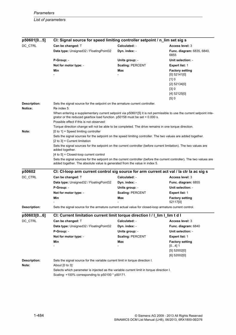
Parameters
List of parameters
1-484 © Siemens AG 2009 - 2013 All Rights ReservedSINAMICS DCM List Manual (LH8), 06/2013, 6RX1800-0ED76
Description: Sets the signal source for the setpoint on the armature current controller.
Notice: Re index 5:
When entering a supplementary current setpoint via p50601[5] it is not permissible to use the current setpoint inte-grator or the reduced gearbox load function. p50158 must be set = 0.000 s.
Possible effect if this is not observed:
Torque direction change will not be able to be completed. The drive remains in one torque direction.
Note: [0 to 1] = Speed limiting controller
Sets the signal sources for the setpoint on the speed limiting controller. The two values are added together.
[2 to 3] = Current limitation
Sets the signal sources for the setpoint on the current controller (before current limitation). The two values are added together.
[4 to 5] = Closed-loop current control
Sets the signal sources for the setpoint on the current controller (before the current controller). The two values are added together. The absolute value is generated from the value in index 5.
Description: Sets the signal source for the armature current actual value for closed-loop armature current control.
Description: Sets the signal source for the variable current limit in torque direction I.
Note: About [0 to 3]:
Selects which parameter is injected as the variable current limit in torque direction I.
Scaling: +100% corresponding to p50100 * p50171.
p50601[0...5] CI: Signal source for speed limiting controller setpoint / n_lim set sig sDC_CTRL Can be changed: T Calculated: - Access level: 3
Data type: Unsigned32 / FloatingPoint32 Dyn. index: - Func. diagram: 6835, 6840, 6855
P-Group: - Units group: - Unit selection: -
Not for motor type: - Scaling: PERCENT Expert list: 1
Min Max Factory setting - - [0] 52141[0]
[1] 0
[2] 52134[0]
[3] 0
[4] 52125[0]
[5] 0
p50602 CI: Cl-loop arm current control sig source for arm current act val / Ia ctr Ia ac sig sDC_CTRL Can be changed: T Calculated: - Access level: 3
Data type: Unsigned32 / FloatingPoint32 Dyn. index: - Func. diagram: 6855
P-Group: - Units group: - Unit selection: -
Not for motor type: - Scaling: PERCENT Expert list: 1
Min Max Factory setting - - 52117[0]
p50603[0...6] CI: Current limitation current limit torque direction I / I_lim I_lim t d IDC_CTRL Can be changed: T Calculated: - Access level: 3
Data type: Unsigned32 / FloatingPoint32 Dyn. index: - Func. diagram: 6840
P-Group: - Units group: - Unit selection: -
Not for motor type: - Scaling: PERCENT Expert list: 1
Min Max Factory setting - - [0...4] 1
[5] 52002[0]
[6] 52002[0]

List of parameters
Parameters
1-485© Siemens AG 2009 - 2013 All Rights ReservedSINAMICS DCM List Manual (LH8), 06/2013, 6RX1800-0ED76
About [4]:
Selects which parameter is injected as the current limit in torque direction I for quick stop or shutdown.
Scaling: +100% corresponding to p50100 * p50171.
About [5]:
Selects which parameter is injected as the variable current limit in torque direction I.
Scaling: +100% corresponding to r50072[1].
About [6]:
Selects which parameter is injected as the current limit in torque direction I for quick stop or shutdown.
Scaling: +100% corresponding to r50072[1].
Description: Sets the signal source for the variable current limit in torque direction II.
Note: About [0 to 3]:
Selects which parameter is injected as the variable current limit in torque direction II.
Scaling: +100% corresponding to p50100 * p50171.
About [4]:
Selects which parameter is injected as the current limit in torque direction II for quick stop or shutdown.
Scaling: +100% corresponding to p50100 * p50171.
About [5]:
Selects which parameter is injected as the variable current limit in torque direction II.
Scaling: +100% corresponding to r50072[1].
About [6]:
Selects which parameter is injected as the current limit in torque direction II for quick stop or shutdown.
Scaling: +100% corresponding to r50072[1].
Description: Sets the signal source for the variable positive torque limit.
Note: Scaling:
[0 to 3] = 100% of the parameter value corresponds to the positive system torque limit according to Ia = p50171.
[4] = 100% of the parameter value corresponds to the positive torque limit according to Ia =r50072[1].
p50604[0...6] CI: Current limitation current limit torque direction II / I_lim I_lim t d IIDC_CTRL Can be changed: T Calculated: - Access level: 3
Data type: Unsigned32 / FloatingPoint32 Dyn. index: - Func. diagram: 6840
P-Group: - Units group: - Unit selection: -
Not for motor type: - Scaling: PERCENT Expert list: 1
Min Max Factory setting - - [0] 52135[0]
[1] 52135[1]
[2] 52135[2]
[3] 52135[3]
[4] 52135[4]
[5] 52135[5]
[6] 52135[6]
p50605[0...4] CI: Torque limiting signal source for positive torque limit / T lim pos sig sDC_CTRL Can be changed: T Calculated: - Access level: 3
Data type: Unsigned32 / FloatingPoint32 Dyn. index: - Func. diagram: 6825
P-Group: - Units group: - Unit selection: -
Not for motor type: - Scaling: PERCENT Expert list: 1
Min Max Factory setting - - 52002[0]

Parameters
List of parameters
1-486 © Siemens AG 2009 - 2013 All Rights ReservedSINAMICS DCM List Manual (LH8), 06/2013, 6RX1800-0ED76
Description: Sets the signal source for the variable negative torque limit.
Note: Scaling:
[0 to 3] = 100% of the parameter value corresponds to the negative system torque limit according to Ia = p50171.
[4] = 100% of the parameter value corresponds to the negative torque limit according to Ia =r50072[1].
Description: Sets the signal source for the master drive's torque setpoint.
Description: Sets the signal source for the torque direction setpoint for the auto-reversing stage.
Description: Sets the signal source for the actual value on the speed controller.
Dependency: Refer to: p50083
p50606[0...4] CI: Torque limiting signal source for negative torque limit / T lim neg sig sDC_CTRL Can be changed: T Calculated: - Access level: 3
Data type: Unsigned32 / FloatingPoint32 Dyn. index: - Func. diagram: 6825
P-Group: - Units group: - Unit selection: -
Not for motor type: - Scaling: PERCENT Expert list: 1
Min Max Factory setting - - [0] 52138[0]
[1] 52138[1]
[2] 52138[2]
[3] 52138[3]
[4] 52138[4]
p50607[0...n] CI: Torque limiting signal source for master drive t_set / Mst tq set sig sDC_CTRL Can be changed: T Calculated: - Access level: 3
Data type: Unsigned32 / FloatingPoint32 Dyn. index: CDS, p0170 Func. diagram: 6830
P-Group: - Units group: - Unit selection: -
Not for motor type: - Scaling: PERCENT Expert list: 1
Min Max Factory setting - - 52148[0]
p50608 CI: Auto-reversing stage signal source for torque direction setpoint / Tqe dir set sig sDC_CTRL Can be changed: T Calculated: - Access level: 3
Data type: Unsigned32 / FloatingPoint32 Dyn. index: - Func. diagram: 6860
P-Group: - Units group: - Unit selection: -
Not for motor type: - Scaling: PERCENT Expert list: 1
Min Max Factory setting - - 52119[0]
p50609[0...n] CI: Signal source for speed controller actual value / n_ctr act sig sDC_CTRL Can be changed: T Calculated: - Access level: 3
Data type: Unsigned32 / FloatingPoint32 Dyn. index: CDS, p0170 Func. diagram: 6810
P-Group: - Units group: - Unit selection: -
Not for motor type: - Scaling: PERCENT Expert list: 1
Min Max Factory setting - - 0

List of parameters
Parameters
1-487© Siemens AG 2009 - 2013 All Rights ReservedSINAMICS DCM List Manual (LH8), 06/2013, 6RX1800-0ED76
Description: Sets the signal source for the input value on the field gating unit.
Description: Sets the signal sources for generating the field current setpoint (CO: r52275).
Dependency: Refer to: r52275
Description: Sets the signal source for the field current actual value for closed-loop field current control.
Description: Sets the signal sources for generating the upper limit of the field current setpoint (CO: r52273).
Dependency: Refer to: r50073, p50102, r52273
Description: Sets the signal sources for generating the lower limit of the field current setpoint (CO: r52274).
p50610 CI: Signal source for field gating unit input value / Field g unit sig sDC_CTRL Can be changed: T Calculated: - Access level: 3
Data type: Unsigned32 / FloatingPoint32 Dyn. index: - Func. diagram: 6915
P-Group: - Units group: - Unit selection: -
Not for motor type: - Scaling: PERCENT Expert list: 1
Min Max Factory setting - - 52252[0]
p50611[0...3] CI: Field curr setp limiting setpoint sig source / If_lim set sig sDC_CTRL Can be changed: T Calculated: - Access level: 3
Data type: Unsigned32 / FloatingPoint32 Dyn. index: - Func. diagram: 6905
P-Group: - Units group: - Unit selection: -
Not for motor type: - Scaling: PERCENT Expert list: 1
Min Max Factory setting - - [0] 52277[0]
[1] 0
[2] 0
[3] 0
p50612[0...1] CI: Cl-loop field current ctrl sig source for field current act val / If_ctr If_ac sig sDC_CTRL Can be changed: T Calculated: - Access level: 3
Data type: Unsigned32 / FloatingPoint32 Dyn. index: - Func. diagram: 6910
P-Group: - Units group: - Unit selection: -
Not for motor type: - Scaling: PERCENT Expert list: 1
Min Max Factory setting - - [0] 52266[0]
[1] 0
p50613[0...4] CI: Field current setpoint limiting sig source for var upper limit / If_li up li sig sDC_CTRL Can be changed: T Calculated: - Access level: 3
Data type: Unsigned32 / FloatingPoint32 Dyn. index: - Func. diagram: 6905
P-Group: - Units group: - Unit selection: -
Not for motor type: - Scaling: PERCENT Expert list: 1
Min Max Factory setting - - 1
p50614[0...4] CI: Field current setpoint limiting sig source for var lower limit / If_lim l lim sig sDC_CTRL Can be changed: T Calculated: - Access level: 3
Data type: Unsigned32 / FloatingPoint32 Dyn. index: - Func. diagram: 6905
P-Group: - Units group: - Unit selection: -
Not for motor type: - Scaling: PERCENT Expert list: 1
Min Max Factory setting - - [0...3] 1
[4] 0

Parameters
List of parameters
1-488 © Siemens AG 2009 - 2013 All Rights ReservedSINAMICS DCM List Manual (LH8), 06/2013, 6RX1800-0ED76
Dependency: Refer to: p50103, r52274
Description: Sets the signal source for the setpoints on the EMF controller.
Index: [0] = Setpoint 0[1] = Setpoint 1[2] = Setpoint 2[3] = Setpoint 3
Dependency: Refer to: r52288
Note: The overall setpoint is available via connector output r52288 for further interconnection.
Description: Sets the signal source for the actual value on the EMF controller.
Dependency: Refer to: r52285
Note: The actual value is available via connector output r52285 for further interconnection.
Description: Sets the signal source for the field direction on the field gating unit.
Description: Sets the signal source for the acceleration value for inertia compensation.
p50615[0...3] CI: EMF controller setpoint signal source / EMF ctr set sig sDC_CTRL Can be changed: T Calculated: - Access level: 3
Data type: Unsigned32 / FloatingPoint32 Dyn. index: - Func. diagram: 6900
P-Group: - Units group: - Unit selection: -
Not for motor type: - Scaling: PERCENT Expert list: 1
Min Max Factory setting - - [0] 52289[0]
[1] 0
[2] 0
[3] 0
p50616 CI: EMF controller actual value signal source / EMF ctr act sig sDC_CTRL Can be changed: T Calculated: - Access level: 3
Data type: Unsigned32 / FloatingPoint32 Dyn. index: - Func. diagram: 6900
P-Group: - Units group: - Unit selection: -
Not for motor type: - Scaling: PERCENT Expert list: 1
Min Max Factory setting - - 52286[0]
p50618 CI: Field gating unit signal source for field direction / Field g unit dirDC_CTRL Can be changed: T Calculated: - Access level: 3
Data type: Unsigned32 / FloatingPoint32 Dyn. index: - Func. diagram: 6915
P-Group: - Units group: - Unit selection: -
Not for motor type: - Scaling: PERCENT Expert list: 1
Min Max Factory setting - - 52268[0]
p50619 CI: Acceleration value for inertia compensation / Comp inert acc valDC_CTRL Can be changed: T Calculated: - Access level: 3
Data type: Unsigned32 / FloatingPoint32 Dyn. index: - Func. diagram: 6820
P-Group: - Units group: - Unit selection: -
Not for motor type: - Scaling: PERCENT Expert list: 1
Min Max Factory setting - - 52191[0]

List of parameters
Parameters
1-489© Siemens AG 2009 - 2013 All Rights ReservedSINAMICS DCM List Manual (LH8), 06/2013, 6RX1800-0ED76
Description: Sets the signal source for the setpoint/actual value difference on the speed controller.
Dependency: Refer to: r52164
Note: The setpoint/actual value difference for the speed controller is available in r52164 for further interconnection.
Description: Sets the signal source for setpoint 1 on the speed controller.
Dependency: Refer to: p50622, p50623, p50624, r52165
Note: The setpoint/actual value difference (r52165) results from setpoint 1 and 2 (p50621, p50622) and actual value 1 and 2 (p50623, p50624).
Description: Sets the signal source for setpoint 2 on the speed controller.
Dependency: Refer to: p50621, p50623, p50624, r52165
Note: The setpoint/actual value difference (r52165) results from setpoint 1 and 2 (p50621, p50622) and actual value 1 and 2 (p50623, p50624).
Description: Sets the signal source for actual value 1 on the speed controller.
Dependency: Refer to: p50621, p50622, p50624, r52165
Note: The setpoint/actual value difference (r52165) results from setpoint 1 and 2 (p50621, p50622) and actual value 1 and 2 (p50623, p50624).
p50620 CI: Speed controller setpoint/actual value difference signal source / n_ctr set/ac sig sDC_CTRL Can be changed: T Calculated: - Access level: 3
Data type: Unsigned32 / FloatingPoint32 Dyn. index: - Func. diagram: 6815
P-Group: - Units group: - Unit selection: -
Not for motor type: - Scaling: PERCENT Expert list: 1
Min Max Factory setting - - 52165[0]
p50621 CI: Speed controller setpoint 1 signal source / n_ctr set 1 sig sDC_CTRL Can be changed: T Calculated: - Access level: 3
Data type: Unsigned32 / FloatingPoint32 Dyn. index: - Func. diagram: 6810
P-Group: - Units group: - Unit selection: -
Not for motor type: - Scaling: PERCENT Expert list: 1
Min Max Factory setting - - 52176[0]
p50622 CI: Speed controller setpoint 2 signal source / n_ctr set 2 sig sDC_CTRL Can be changed: T Calculated: - Access level: 3
Data type: Unsigned32 / FloatingPoint32 Dyn. index: - Func. diagram: 6810
P-Group: - Units group: - Unit selection: -
Not for motor type: - Scaling: PERCENT Expert list: 1
Min Max Factory setting - - 52174[0]
p50623 CI: Signal source for speed controller actual value 1 / n_ctr act 1 sig sDC_CTRL Can be changed: T Calculated: - Access level: 3
Data type: Unsigned32 / FloatingPoint32 Dyn. index: - Func. diagram: 6810
P-Group: - Units group: - Unit selection: -
Not for motor type: - Scaling: PERCENT Expert list: 1
Min Max Factory setting - - 52179[0]
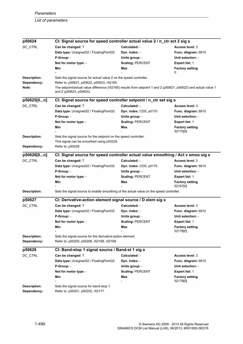
Parameters
List of parameters
1-490 © Siemens AG 2009 - 2013 All Rights ReservedSINAMICS DCM List Manual (LH8), 06/2013, 6RX1800-0ED76
Description: Sets the signal source for actual value 2 on the speed controller.
Dependency: Refer to: p50621, p50622, p50623, r52165
Note: The setpoint/actual value difference (r52165) results from setpoint 1 and 2 (p50621, p50622) and actual value 1 and 2 (p50623, p50624).
Description: Sets the signal source for the setpoint on the speed controller.
This signal can be smoothed using p50228.
Dependency: Refer to: p50228
Description: Sets the signal source to enable smoothing of the actual value on the speed controller.
Description: Sets the signal source for the derivative-action element.
Dependency: Refer to: p50205, p50206, r52168, r52169
Description: Sets the signal source for band-stop 1.
Dependency: Refer to: p50201, p50202, r52177
p50624 CI: Signal source for speed controller actual value 2 / n_ctr act 2 sig sDC_CTRL Can be changed: T Calculated: - Access level: 3
Data type: Unsigned32 / FloatingPoint32 Dyn. index: - Func. diagram: 6810
P-Group: - Units group: - Unit selection: -
Not for motor type: - Scaling: PERCENT Expert list: 1
Min Max Factory setting - - 0
p50625[0...n] CI: Signal source for speed controller setpoint / n_ctr set sig sDC_CTRL Can be changed: T Calculated: - Access level: 3
Data type: Unsigned32 / FloatingPoint32 Dyn. index: CDS, p0170 Func. diagram: 6810
P-Group: - Units group: - Unit selection: -
Not for motor type: - Scaling: PERCENT Expert list: 1
Min Max Factory setting - - 52170[0]
p50626[0...n] CI: Signal source for speed controller actual value smoothing / Act v smoo sig sDC_CTRL Can be changed: T Calculated: - Access level: 3
Data type: Unsigned32 / FloatingPoint32 Dyn. index: CDS, p0170 Func. diagram: 6810
P-Group: - Units group: - Unit selection: -
Not for motor type: - Scaling: PERCENT Expert list: 1
Min Max Factory setting - - 52167[0]
p50627 CI: Derivative-action element signal source / D elem sig sDC_CTRL Can be changed: T Calculated: - Access level: 3
Data type: Unsigned32 / FloatingPoint32 Dyn. index: - Func. diagram: 6810
P-Group: - Units group: - Unit selection: -
Not for motor type: - Scaling: PERCENT Expert list: 1
Min Max Factory setting - - 52178[0]
p50628 CI: Band-stop 1 signal source / Band-st 1 sig sDC_CTRL Can be changed: T Calculated: - Access level: 3
Data type: Unsigned32 / FloatingPoint32 Dyn. index: - Func. diagram: 6810
P-Group: - Units group: - Unit selection: -
Not for motor type: - Scaling: PERCENT Expert list: 1
Min Max Factory setting - - 52179[0]

List of parameters
Parameters
1-491© Siemens AG 2009 - 2013 All Rights ReservedSINAMICS DCM List Manual (LH8), 06/2013, 6RX1800-0ED76
Description: Sets the signal source for band-stop 2.
Dependency: Refer to: p50203, p50204, r52178
Description: Sets the signal source for the droop on the speed controller.
Description: Sets the signal source for the setting value of the integral component for the speed controller.
Dependency: Refer to: p50230, p50695
Description: Sets the signal sources for positive limiting after the ramp-function generator (setpoint limiting).
Note: The minimum of the signals is forwarded to the limiter via connector input p50632[0 to 3].
Description: Sets the signal sources for negative limiting after the ramp-function generator (setpoint limiting).
Note: The maximum of the signals is forwarded to the limiter via connector input p50633[0 to 3].
p50629 CI: Band-stop 2 signal source / Band-st 2 sig sDC_CTRL Can be changed: T Calculated: - Access level: 3
Data type: Unsigned32 / FloatingPoint32 Dyn. index: - Func. diagram: 6810
P-Group: - Units group: - Unit selection: -
Not for motor type: - Scaling: PERCENT Expert list: 1
Min Max Factory setting - - 52177[0]
p50630 CI: Speed controller droop signal source / Droop sig sDC_CTRL Can be changed: T Calculated: - Access level: 3
Data type: Unsigned32 / FloatingPoint32 Dyn. index: - Func. diagram: 6805
P-Group: - Units group: - Unit selection: -
Not for motor type: - Scaling: PERCENT Expert list: 1
Min Max Factory setting - - 52162[0]
p50631 CI: Speed controller integral component setting value signal source / I_co set v sig sDC_CTRL Can be changed: T Calculated: - Access level: 3
Data type: Unsigned32 / FloatingPoint32 Dyn. index: - Func. diagram: 6815
P-Group: - Units group: - Unit selection: -
Not for motor type: - Scaling: PERCENT Expert list: 1
Min Max Factory setting - - 0
p50632[0...3] CI: RFG signal source for positive limiting after RFG / RFG pos lim sig sDC_CTRL Can be changed: T Calculated: - Access level: 3
Data type: Unsigned32 / FloatingPoint32 Dyn. index: - Func. diagram: 3155
P-Group: - Units group: - Unit selection: -
Not for motor type: - Scaling: PERCENT Expert list: 1
Min Max Factory setting - - 1
p50633[0...3] CI: RFG signal source for negative limiting after RFG / RFG neg lim sig sDC_CTRL Can be changed: T Calculated: - Access level: 3
Data type: Unsigned32 / FloatingPoint32 Dyn. index: - Func. diagram: 3155
P-Group: - Units group: - Unit selection: -
Not for motor type: - Scaling: PERCENT Expert list: 1
Min Max Factory setting - - [0] 52210[0]
[1] 52210[1]
[2] 52210[2]
[3] 52210[3]

Parameters
List of parameters
1-492 © Siemens AG 2009 - 2013 All Rights ReservedSINAMICS DCM List Manual (LH8), 06/2013, 6RX1800-0ED76
Description: Sets the signal sources for the input signals in the case of limiting after the ramp-function generator (setpoint limit-ing).
Note: The signals via connector input p50634[0 to 1] are added to the input and forwarded to "Limiting after ramp-function generator".
Description: Sets the signal source for the ramp-function generator's setpoint.
Description: Sets the signal sources for the valuation factors for ramp-function generator parameter set 1.
Index: [0] = Ramp-up time and ramp-down time[1] = Initial rounding and final rounding[2] = Ramp-up time[3] = Ramp-down time[4] = Initial rounding[5] = Final rounding
Dependency: Refer to: p50303, p50304, p50305, p50306
Note: The valuation factors affect the set values of the following parameters:
- p50303: Ramp-up time 1
- p50304: Ramp-down time 1
- p50305: Initial rounding 1
- p50306: Final rounding 1
Description: Sets the signal source for the selection of "ramp-function generator parameter set 2".
1 signal:
RFG parameter set 2 is effective (p50307, p50308, p50309, p50310).
p50634[0...1] CI: RFG input signal for limiting after RFG / RFG lim inp sigDC_CTRL Can be changed: T Calculated: - Access level: 3
Data type: Unsigned32 / FloatingPoint32 Dyn. index: - Func. diagram: 3155
P-Group: - Units group: - Unit selection: -
Not for motor type: - Scaling: PERCENT Expert list: 1
Min Max Factory setting - - [0] 52190[0]
[1] 0
p50635[0...n] CI: Setpoint processing signal source for RFG setpoint / RFG set sig sDC_CTRL Can be changed: T Calculated: - Access level: 3
Data type: Unsigned32 / FloatingPoint32 Dyn. index: CDS, p0170 Func. diagram: 3135
P-Group: - Units group: - Unit selection: -
Not for motor type: - Scaling: PERCENT Expert list: 1
Min Max Factory setting - - 52194[0]
p50636[0...5] CI: RFG signal source for valuation factor 1 / RFG val_f 1 sig sDC_CTRL Can be changed: T Calculated: - Access level: 3
Data type: Unsigned32 / FloatingPoint32 Dyn. index: - Func. diagram: 3150
P-Group: - Units group: - Unit selection: -
Not for motor type: - Scaling: PERCENT Expert list: 1
Min Max Factory setting - - 1
p50637[0...n] BI: RFG parameter set 2 selection signal source / RFG par s 2 sig sDC_CTRL Can be changed: T Calculated: - Access level: 3
Data type: Unsigned32 / Binary Dyn. index: CDS, p0170 Func. diagram: 3150
P-Group: - Units group: - Unit selection: -
Not for motor type: - Scaling: - Expert list: 1
Min Max Factory setting - - 0

List of parameters
Parameters
1-493© Siemens AG 2009 - 2013 All Rights ReservedSINAMICS DCM List Manual (LH8), 06/2013, 6RX1800-0ED76
Dependency: Refer to: p50307, p50308, p50309, p50310, p50638
Note: The following applies as regards selection of ramp-function generator parameter set 2:
- This selection has a higher priority than selection by means of the ramp-up integrator.
- This selection has a lower priority than quick stop (OFF3); in other words, in the event of a quick stop (OFF3) the values set in p50296, p50297, and p50298 become effective.
- A corresponding message is output if ramp-function generator parameter sets 2 and 3 are selected at the same time.
Description: Sets the signal source for the selection of "ramp-function generator parameter set 3".
1 signal:
RFG parameter set 3 is effective (p50311, p50312, p50313, p50314).
Dependency: Refer to: p50311, p50312, p50313, p50314, p50637
Note: The following applies as regards selection of ramp-function generator parameter set 3:
- This selection has a higher priority than selection by means of the ramp-up integrator.
- This selection has a lower priority than quick stop (OFF3); in other words, in the event of a quick stop (OFF3) the values set in p50296, p50297, and p50298 become effective.
- A corresponding message is output if ramp-function generator parameter sets 2 and 3 are selected at the same time.
Description: Sets the signal source for the ramp-function generator's setting values.
Index: [0] = Setting value[1] = Setting value if machine is not running
Dependency: The setting value for the ramp-function generator output is selected via binector input p50640.
p50640 = 0 signal:
If the machine is not running, the value supplied via connector input p50639[1] is accepted.
p50640 = 1 signal:
The value supplied via connector input p50639[0] is accepted as the setting value.
Refer to: p50640
Description: Sets the signal source for accepting the setting value of the ramp-function generator.
Dependency: Refer to: p50639
p50638[0...n] BI: RFG parameter set 3 selection signal source / RFG par s 3 sig sDC_CTRL Can be changed: T Calculated: - Access level: 3
Data type: Unsigned32 / Binary Dyn. index: CDS, p0170 Func. diagram: 3150
P-Group: - Units group: - Unit selection: -
Not for motor type: - Scaling: - Expert list: 1
Min Max Factory setting - - 0
p50639[0...1] CI: RFG signal source for setting value / RFG set val sig sDC_CTRL Can be changed: T Calculated: - Access level: 3
Data type: Unsigned32 / FloatingPoint32 Dyn. index: - Func. diagram: 3152
P-Group: - Units group: - Unit selection: -
Not for motor type: - Scaling: PERCENT Expert list: 1
Min Max Factory setting - - 52167[0]
p50640[0...n] BI: RFG signal source for accepting setting value / RFG accept set vDC_CTRL Can be changed: T Calculated: - Access level: 3
Data type: Unsigned32 / Binary Dyn. index: CDS, p0170 Func. diagram: 3152
P-Group: - Units group: - Unit selection: -
Not for motor type: - Scaling: - Expert list: 1
Min Max Factory setting - - 0

Parameters
List of parameters
1-494 © Siemens AG 2009 - 2013 All Rights ReservedSINAMICS DCM List Manual (LH8), 06/2013, 6RX1800-0ED76
Description: Sets the signal source for "Bypass ramp-function generator".
Note: The "Bypass ramp-function generator" signal can also be set via binector input p50649[0 to 2].
Description: Sets the signal source for variable positive limiting of the main setpoint.
Notice: Negative values at the selected parameters generate a negative maximum value at the limiting output.
Note: The minimum of the values set via index 0 to 3 is applied as the limit.
Description: Sets the signal source for variable positive limiting of the main setpoint.
Notice: Positive values at the selected parameters generate a positive minimum value at the limiting output.
Note: The maximum of the values set via index 0 to 3 is applied as the limit.
Description: Sets the signal source for the main setpoint in the context of setpoint processing.
Dependency: Refer to: p50320, p50322
p50641[0...n] BI: Bypass ramp-function generator signal source / Bypass RFG sig sDC_CTRL Can be changed: T Calculated: - Access level: 3
Data type: Unsigned32 / Binary Dyn. index: CDS, p0170 Func. diagram: 3152
P-Group: - Units group: - Unit selection: -
Not for motor type: - Scaling: - Expert list: 1
Min Max Factory setting - - 0
p50642[0...3] CI: Setpoint processing sig source for pos limiting of main setpoint / M set lim p sig sDC_CTRL Can be changed: T Calculated: - Access level: 3
Data type: Unsigned32 / FloatingPoint32 Dyn. index: - Func. diagram: 3135
P-Group: - Units group: - Unit selection: -
Not for motor type: - Scaling: PERCENT Expert list: 1
Min Max Factory setting - - 52002[0]
p50643[0...3] CI: Setpoint processing sig source for neg limiting of main setpoint / M set lim n sig sDC_CTRL Can be changed: T Calculated: - Access level: 3
Data type: Unsigned32 / FloatingPoint32 Dyn. index: - Func. diagram: 3135
P-Group: - Units group: - Unit selection: -
Not for motor type: - Scaling: PERCENT Expert list: 1
Min Max Factory setting - - [0] 52184[0]
[1] 52185[0]
[2] 52186[0]
[3] 52187[0]
p50644[0...n] CI: Setpoint processing signal source for main setpoint / M set sig sDC_CTRL Can be changed: T Calculated: - Access level: 3
Data type: Unsigned32 / FloatingPoint32 Dyn. index: CDS, p0170 Func. diagram: 3135
P-Group: - Units group: - Unit selection: -
Not for motor type: - Scaling: PERCENT Expert list: 1
Min Max Factory setting - - 52206[0]

List of parameters
Parameters
1-495© Siemens AG 2009 - 2013 All Rights ReservedSINAMICS DCM List Manual (LH8), 06/2013, 6RX1800-0ED76
Description: Sets the signal source for the additional setpoint in the context of setpoint processing.
Dependency: Refer to: p50321, p50323
Description: Sets the signal source for enabling the ramp-up integrator on the ramp-function generator.
Description: Sets the signal source for activating/de-activating ramp-function generator tracking.
Dependency: The enable for ramp-function generator tracking must be available (p50317 = 1).
Refer to: p50317
Description: Sets the signal source for the ramp-function generator's input signal.
Description: Sets the signal sources for "Bypass ramp-function generator".
Dependency: Refer to: p50641
p50645[0...n] CI: Setpoint processing signal source for additional setpoint / A set sig sDC_CTRL Can be changed: T Calculated: - Access level: 3
Data type: Unsigned32 / FloatingPoint32 Dyn. index: CDS, p0170 Func. diagram: 3135
P-Group: - Units group: - Unit selection: -
Not for motor type: - Scaling: PERCENT Expert list: 1
Min Max Factory setting - - 0
p50646[0...n] BI: RFG signal source for ramp-up integrator enable / R-up int ena sig sDC_CTRL Can be changed: T Calculated: - Access level: 3
Data type: Unsigned32 / Binary Dyn. index: CDS, p0170 Func. diagram: 3150
P-Group: - Units group: - Unit selection: -
Not for motor type: - Scaling: - Expert list: 1
Min Max Factory setting - - 1
p50647[0...n] BI: RFG tracking activation signal source / RFG trck act sig sDC_CTRL Can be changed: T Calculated: - Access level: 3
Data type: Unsigned32 / Binary Dyn. index: CDS, p0170 Func. diagram: 3152
P-Group: - Units group: - Unit selection: -
Not for motor type: - Scaling: - Expert list: 1
Min Max Factory setting - - 0
p50648 CI: RFG signal source for input signal / RFG inp sig sig sDC_CTRL Can be changed: T Calculated: - Access level: 3
Data type: Unsigned32 / FloatingPoint32 Dyn. index: - Func. diagram: 3151
P-Group: - Units group: - Unit selection: -
Not for motor type: - Scaling: PERCENT Expert list: 1
Min Max Factory setting - - 52193[0]
p50649[0...2] BI: Bypass ramp-function generator signal source / Bypass RFG sig sDC_CTRL Can be changed: T Calculated: - Access level: 3
Data type: Unsigned32 / Binary Dyn. index: - Func. diagram: 3152
P-Group: - Units group: - Unit selection: -
Not for motor type: - Scaling: - Expert list: 1
Min Max Factory setting - - [0] 53170.10
[1] 53170.11
[2] 53170.12

Parameters
List of parameters
1-496 © Siemens AG 2009 - 2013 All Rights ReservedSINAMICS DCM List Manual (LH8), 06/2013, 6RX1800-0ED76
Note: The "Bypass ramp-function generator" signal can also be set via binector input p50641.
About index 0, 1, 2 and their factory setting:
The "Bypass ramp-function generator" signal comes from the "Fixed setpoint", "Jog setpoint", "Creep setpoint" function.
Description: Sets the signal sources for the ramp-function generator's setting value with OFF1.
The ramp-function generator is set to this value once.
Index: [0] = Setting value 1[1] = Setting value 2
Dependency: The selection of the signal source for the setting value is set via p50318.
p50318 = 0: Do not set ramp-function generator output
p50318 = 1: Set ramp-function generator output to the value supplied via connector input p50650[0].
p50318 = 2: Set ramp-function generator output to the value supplied via connector input p50650[1].
Refer to: p50318
Description: Sets the signal sources for the effective limits for ramp-function generator tracking.
Index: [0] = Scaled motor flux[1] = Speed actual value[2] = Effective positive torque limit[3] = Effective negative torque limit[4] = Effective positive current limit[5] = Effective negative current limit[6] = Effective speed controller proportional gain
Description: Sets the signal source to enable the negative direction of rotation.
Dependency: Refer to: p50672
p50650[0...1] CI: RFG signal source for setting value with OFF1 / RFG s v OFF1 sig sDC_CTRL Can be changed: T Calculated: - Access level: 3
Data type: Unsigned32 / FloatingPoint32 Dyn. index: - Func. diagram: 3152
P-Group: - Units group: - Unit selection: -
Not for motor type: - Scaling: PERCENT Expert list: 1
Min Max Factory setting - - [0] 52167[0]
[1] 52179[0]
p50651[0...6] CI: RFG tracking signal sources / RFG track sig sDC_CTRL Can be changed: T Calculated: - Access level: 3
Data type: Unsigned32 / FloatingPoint32 Dyn. index: - Func. diagram: 3152
P-Group: - Units group: - Unit selection: -
Not for motor type: - Scaling: PERCENT Expert list: 1
Min Max Factory setting - - [0] 52290[0]
[1] 52167[0]
[2] 52143[0]
[3] 52144[0]
[4] 52131[0]
[5] 52132[0]
[6] 50219[0]
p50671[0...n] BI: Setpoint processing sig source to enable neg dir of rotation / Ena n dir r sig sDC_CTRL Can be changed: U, T Calculated: - Access level: 2
Data type: Unsigned32 / Binary Dyn. index: CDS, p0170 Func. diagram: 3135
P-Group: - Units group: - Unit selection: -
Not for motor type: - Scaling: - Expert list: 1
Min Max Factory setting - - 1

List of parameters
Parameters
1-497© Siemens AG 2009 - 2013 All Rights ReservedSINAMICS DCM List Manual (LH8), 06/2013, 6RX1800-0ED76
Note: 1 signal: Negative direction of rotation enabled
0 signal: Negative direction of rotation disabled
Description: Sets the signal source to enable the positive direction of rotation.
Dependency: Refer to: p50671
Note: 1 signal: Positive direction of rotation enabled
0 signal: Positive direction of rotation disabled
Description: Sets the signal source to increase the setpoint for the motorized potentiometer.
Dependency: Refer to: p50471
Note: This parameter is only effective in manual mode (p50471 = 0).
Description: Sets the signal source to lower the setpoint for the motorized potentiometer.
Dependency: Refer to: p50471
Note: This parameter is only effective in manual mode (p50471 = 0).
Description: Sets the signal source for the selection of connector 0 (p50431[0]).
Dependency: Refer to: p50430, p50431
p50672[0...n] BI: Setpoint processing signal source to enable pos dir of rotation / Ena p dir r sig sDC_CTRL Can be changed: U, T Calculated: - Access level: 2
Data type: Unsigned32 / Binary Dyn. index: CDS, p0170 Func. diagram: 3135
P-Group: - Units group: - Unit selection: -
Not for motor type: - Scaling: - Expert list: 1
Min Max Factory setting - - 1
p50673[0...n] BI: Motorized potentiometer signal source to increase setpoint / MotP incr sig sDC_CTRL Can be changed: T Calculated: - Access level: 2
Data type: Unsigned32 / Binary Dyn. index: CDS, p0170 Func. diagram: 3110
P-Group: - Units group: - Unit selection: -
Not for motor type: - Scaling: - Expert list: 1
Min Max Factory setting - - 0
p50674[0...n] BI: Motorized potentiometer signal source to lower setpoint / MotP lower sig sDC_CTRL Can be changed: T Calculated: - Access level: 2
Data type: Unsigned32 / Binary Dyn. index: CDS, p0170 Func. diagram: 3110
P-Group: - Units group: - Unit selection: -
Not for motor type: - Scaling: - Expert list: 1
Min Max Factory setting - - 0
p50680[0...n] BI: Fixed setpoint signal source for connector selection 0 / Fix set con0 sig sDC_CTRL Can be changed: T Calculated: - Access level: 2
Data type: Unsigned32 / Binary Dyn. index: CDS, p0170 Func. diagram: 3115
P-Group: - Units group: - Unit selection: -
Not for motor type: - Scaling: - Expert list: 1
Min Max Factory setting - - 0

Parameters
List of parameters
1-498 © Siemens AG 2009 - 2013 All Rights ReservedSINAMICS DCM List Manual (LH8), 06/2013, 6RX1800-0ED76
Description: Sets the signal source for the selection of connector 1 (p50431[1]).
Dependency: Refer to: p50430, p50431
Description: Sets the signal source to enable droop on the speed controller.
Note: The following values are multiplied by the droop output dependent upon the signal state:
1 signal: Enable (r50630)
0 signal: No enable (0%)
Description: Sets the signal source for the master or slave drive on the speed controller.
Note: 1 signal:
Torque control is active on the slave drive.
0 signal:
Speed control is active on the master drive.
Description: Sets the signal source for feedback from the line contactor.
The feedback signal is checked and fault F60104 is triggered in the following cases:
- If, following power-up, a 1 signal is not detected within the time set in p50095 (in other words, if the line contactor has not closed).
- If a 0 signal is detected during operation.
Note: Feedback from the line contactor can be achieved by integrating one of the line contactor's auxiliary contacts into the device control.
p50681[0...n] BI: Fixed setpoint signal source for connector selection 1 / Fix set con1 sig sDC_CTRL Can be changed: T Calculated: - Access level: 2
Data type: Unsigned32 / Binary Dyn. index: CDS, p0170 Func. diagram: 3115
P-Group: - Units group: - Unit selection: -
Not for motor type: - Scaling: - Expert list: 1
Min Max Factory setting - - 0
p50684[0...n] BI: Speed controller droop enable / Droop enableDC_CTRL Can be changed: T Calculated: - Access level: 2
Data type: Unsigned32 / Binary Dyn. index: CDS, p0170 Func. diagram: 6805
P-Group: - Units group: - Unit selection: -
Not for motor type: - Scaling: - Expert list: 1
Min Max Factory setting - - 1
p50687[0...n] BI: Speed controller signal source for master/slave drive / Mast/sl sig sDC_CTRL Can be changed: T Calculated: - Access level: 2
Data type: Unsigned32 / Binary Dyn. index: CDS, p0170 Func. diagram: 6810, 6830
P-Group: - Units group: - Unit selection: -
Not for motor type: - Scaling: - Expert list: 1
Min Max Factory setting - - 0
p50691[0...n] BI: Sequence control line contactor feedback / Line cont feedbDC_CTRL Can be changed: T Calculated: - Access level: 2
Data type: Unsigned32 / Binary Dyn. index: CDS, p0170 Func. diagram: 2651
P-Group: - Units group: - Unit selection: -
Not for motor type: - Scaling: - Expert list: 1
Min Max Factory setting - - 1
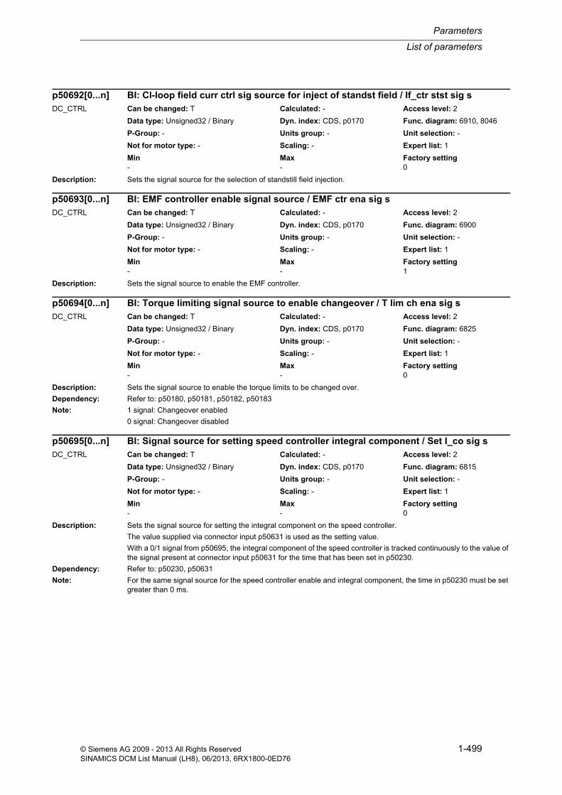
List of parameters
Parameters
1-499© Siemens AG 2009 - 2013 All Rights ReservedSINAMICS DCM List Manual (LH8), 06/2013, 6RX1800-0ED76
Description: Sets the signal source for the selection of standstill field injection.
Description: Sets the signal source to enable the EMF controller.
Description: Sets the signal source to enable the torque limits to be changed over.
Dependency: Refer to: p50180, p50181, p50182, p50183
Note: 1 signal: Changeover enabled
0 signal: Changeover disabled
Description: Sets the signal source for setting the integral component on the speed controller.
The value supplied via connector input p50631 is used as the setting value.
With a 0/1 signal from p50695, the integral component of the speed controller is tracked continuously to the value of the signal present at connector input p50631 for the time that has been set in p50230.
Dependency: Refer to: p50230, p50631
Note: For the same signal source for the speed controller enable and integral component, the time in p50230 must be set greater than 0 ms.
p50692[0...n] BI: Cl-loop field curr ctrl sig source for inject of standst field / If_ctr stst sig sDC_CTRL Can be changed: T Calculated: - Access level: 2
Data type: Unsigned32 / Binary Dyn. index: CDS, p0170 Func. diagram: 6910, 8046
P-Group: - Units group: - Unit selection: -
Not for motor type: - Scaling: - Expert list: 1
Min Max Factory setting - - 0
p50693[0...n] BI: EMF controller enable signal source / EMF ctr ena sig sDC_CTRL Can be changed: T Calculated: - Access level: 2
Data type: Unsigned32 / Binary Dyn. index: CDS, p0170 Func. diagram: 6900
P-Group: - Units group: - Unit selection: -
Not for motor type: - Scaling: - Expert list: 1
Min Max Factory setting - - 1
p50694[0...n] BI: Torque limiting signal source to enable changeover / T lim ch ena sig sDC_CTRL Can be changed: T Calculated: - Access level: 2
Data type: Unsigned32 / Binary Dyn. index: CDS, p0170 Func. diagram: 6825
P-Group: - Units group: - Unit selection: -
Not for motor type: - Scaling: - Expert list: 1
Min Max Factory setting - - 0
p50695[0...n] BI: Signal source for setting speed controller integral component / Set I_co sig sDC_CTRL Can be changed: T Calculated: - Access level: 2
Data type: Unsigned32 / Binary Dyn. index: CDS, p0170 Func. diagram: 6815
P-Group: - Units group: - Unit selection: -
Not for motor type: - Scaling: - Expert list: 1
Min Max Factory setting - - 0

Parameters
List of parameters
1-500 © Siemens AG 2009 - 2013 All Rights ReservedSINAMICS DCM List Manual (LH8), 06/2013, 6RX1800-0ED76
Description: Sets the signal source for stopping the integral component on the speed controller.
Note: Dependent upon the signal state, the following applies:
0 signal: Integral component is not stopped
1 signal: Integral component is stopped
Description: Sets the signal source for enabling moment of inertia compensation.
Note: Dependent upon the signal state, the following values are added to the output for friction and moment of inertia compensation:
1 signal: Enable (r52173)
0 signal: No enable (0%)
Description: Sets the signal source for the speed-dependent changeover between PI and P controller on the speed controller.
Dependency: Refer to: p50221, p50222, r52166
Description: Sets the type for analog input 0 (X177.25/26) on the CUD.
Value: 0: Bipolar voltage input (-10 V ... +10 V)1: Bipolar current input (-20 mA to +20 mA)2: Unipolar current input monitored (+4 mA to +20 mA)
Note: AI: Analog Input
p50696[0...n] BI: Signal source for stop speed controller integral component / Stop I_co sig sDC_CTRL Can be changed: T Calculated: - Access level: 2
Data type: Unsigned32 / Binary Dyn. index: CDS, p0170 Func. diagram: 6815
P-Group: - Units group: - Unit selection: -
Not for motor type: - Scaling: - Expert list: 1
Min Max Factory setting - - 0
p50697[0...n] BI: Enable for inertia compensation / Inert comp enaDC_CTRL Can be changed: T Calculated: - Access level: 2
Data type: Unsigned32 / Binary Dyn. index: CDS, p0170 Func. diagram: 6820
P-Group: - Units group: - Unit selection: -
Not for motor type: - Scaling: - Expert list: 1
Min Max Factory setting - - 1
p50698[0...n] BI: Signal source for speed controller PI/P controller changeover / n_ctr PI/P sig sDC_CTRL Can be changed: T Calculated: - Access level: 2
Data type: Unsigned32 / Binary Dyn. index: CDS, p0170 Func. diagram: 6815
P-Group: - Units group: - Unit selection: -
Not for motor type: - Scaling: - Expert list: 1
Min Max Factory setting - - 1
p50700 CUD analog input 0 type / CUD AI 0 typeDC_CTRL Can be changed: T Calculated: - Access level: 2
Data type: Integer16 Dyn. index: - Func. diagram: 2075
P-Group: - Units group: - Unit selection: -
Not for motor type: - Scaling: - Expert list: 1
Min Max Factory setting 0 2 0
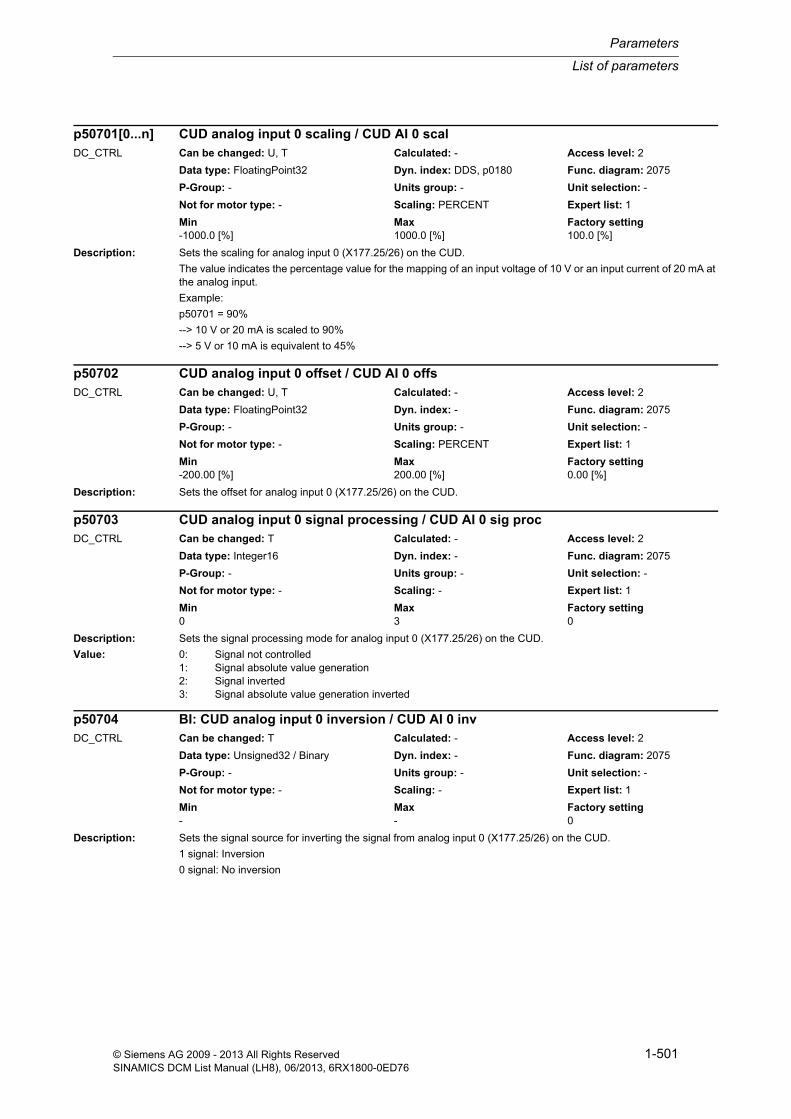
List of parameters
Parameters
1-501© Siemens AG 2009 - 2013 All Rights ReservedSINAMICS DCM List Manual (LH8), 06/2013, 6RX1800-0ED76
Description: Sets the scaling for analog input 0 (X177.25/26) on the CUD.
The value indicates the percentage value for the mapping of an input voltage of 10 V or an input current of 20 mA at the analog input.
Example:
p50701 = 90%
--> 10 V or 20 mA is scaled to 90%
--> 5 V or 10 mA is equivalent to 45%
Description: Sets the offset for analog input 0 (X177.25/26) on the CUD.
Description: Sets the signal processing mode for analog input 0 (X177.25/26) on the CUD.
Value: 0: Signal not controlled1: Signal absolute value generation2: Signal inverted3: Signal absolute value generation inverted
Description: Sets the signal source for inverting the signal from analog input 0 (X177.25/26) on the CUD.
1 signal: Inversion
0 signal: No inversion
p50701[0...n] CUD analog input 0 scaling / CUD AI 0 scalDC_CTRL Can be changed: U, T Calculated: - Access level: 2
Data type: FloatingPoint32 Dyn. index: DDS, p0180 Func. diagram: 2075
P-Group: - Units group: - Unit selection: -
Not for motor type: - Scaling: PERCENT Expert list: 1
Min Max Factory setting -1000.0 [%] 1000.0 [%] 100.0 [%]
p50702 CUD analog input 0 offset / CUD AI 0 offsDC_CTRL Can be changed: U, T Calculated: - Access level: 2
Data type: FloatingPoint32 Dyn. index: - Func. diagram: 2075
P-Group: - Units group: - Unit selection: -
Not for motor type: - Scaling: PERCENT Expert list: 1
Min Max Factory setting -200.00 [%] 200.00 [%] 0.00 [%]
p50703 CUD analog input 0 signal processing / CUD AI 0 sig procDC_CTRL Can be changed: T Calculated: - Access level: 2
Data type: Integer16 Dyn. index: - Func. diagram: 2075
P-Group: - Units group: - Unit selection: -
Not for motor type: - Scaling: - Expert list: 1
Min Max Factory setting 0 3 0
p50704 BI: CUD analog input 0 inversion / CUD AI 0 invDC_CTRL Can be changed: T Calculated: - Access level: 2
Data type: Unsigned32 / Binary Dyn. index: - Func. diagram: 2075
P-Group: - Units group: - Unit selection: -
Not for motor type: - Scaling: - Expert list: 1
Min Max Factory setting - - 0

Parameters
List of parameters
1-502 © Siemens AG 2009 - 2013 All Rights ReservedSINAMICS DCM List Manual (LH8), 06/2013, 6RX1800-0ED76
Description: Sets the time constant for smoothing the signal from analog input 0 (X177.25/26) on the CUD.
Description: Sets the signal source for enabling analog input 0 (X177.25/26) on the CUD.
Note: 1 signal: Analog input enabled
0 signal: Analog input not enabled (r52011 = 0%)
Description: Sets the setpoint for the simulation of analog input 0 (X177.25/26) on the CUD.
Dependency: Refer to: p50709
Note: Simulation is selected using p50709 = 1.
Description: Setting to activate/de-activate the synchronization of the analog inputs of two Control Unit DC MASTERs (CUDs).
Value: 0: No synchronized analog inputs1: 6 synchronized analog inputs on left-hand CUD2: 6 synchronized analog inputs on right-hand CUD3: 6 synchronized analog inputs on left-hand and right-hand CUD
Notice: This parameter must always be set to the same value on both CUDs!
Note: If value = 0:
There is no quasi-synchronization of the analog inputs on the two CUDs. Connector outputs r52030[0 to 6] on both CUDs always indicate a value of 0%.
If value = 1:
The analog inputs of the right-hand CUD are interpolated on the left-hand CUD in such a way that 6 simultaneously scanned values appear at the connector outputs r52030[0 to 6] of the left-hand CUD. Connector outputs r52030[0 to 6] on the right-hand CUD always indicate a value of 0%.
p50705 CUD analog input 0 smoothing time constant / CUD AI 0 TDC_CTRL Can be changed: U, T Calculated: - Access level: 2
Data type: FloatingPoint32 Dyn. index: - Func. diagram: 2075
P-Group: - Units group: - Unit selection: -
Not for motor type: - Scaling: - Expert list: 1
Min Max Factory setting 0 [ms] 10000 [ms] 0 [ms]
p50706 BI: CUD analog input 0 signal source for enable / CUD AI 0 ena sig sDC_CTRL Can be changed: T Calculated: - Access level: 2
Data type: Unsigned32 / Binary Dyn. index: - Func. diagram: 2075
P-Group: - Units group: - Unit selection: -
Not for motor type: - Scaling: - Expert list: 1
Min Max Factory setting - - 1
p50707 CUD analog input 0 simulation setpoint / CUD AI 0 sim setpDC_CTRL Can be changed: U, T Calculated: - Access level: 2
Data type: FloatingPoint32 Dyn. index: - Func. diagram: 2075
P-Group: - Units group: - Unit selection: -
Not for motor type: - Scaling: PERCENT Expert list: 1
Min Max Factory setting -130.0 [%] 130.0 [%] 0.0 [%]
p50708 Activation of analog input synchronization / AI sync actDC_CTRL Can be changed: T Calculated: - Access level: 2
Data type: Integer16 Dyn. index: - Func. diagram: 2083
P-Group: - Units group: - Unit selection: -
Not for motor type: - Scaling: - Expert list: 1
Min Max Factory setting 0 3 0

List of parameters
Parameters
1-503© Siemens AG 2009 - 2013 All Rights ReservedSINAMICS DCM List Manual (LH8), 06/2013, 6RX1800-0ED76
If value = 2:
The analog inputs of the left-hand CUD are interpolated on the right-hand CUD in such a way that 6 simultaneously scanned values appear at the connector outputs r52030[0 to 6] of the right-hand CUD. Connector outputs r52030[0 to 6] on the left-hand CUD always indicate a value of 0%.
If value = 3:
The analog inputs of the right-hand CUD are interpolated on the left-hand CUD in such a way that 6 simultaneously scanned values appear at the connector outputs r52030[0 to 6] of the left-hand CUD.
The analog inputs of the left-hand CUD are interpolated on the right-hand CUD in such a way that 6 simultaneously scanned values appear at the connector outputs r52030[0 to 6] of the right-hand CUD.
Description: Setting to select the simulation of analog input 0 (X177.25/26) on the CUD.
Value: 0: Simulation deactivated1: Simulation activated
Dependency: Refer to: p50707
Note: The setpoint for the simulation is set in p50707.
Description: Sets the type for analog input 1 (X177.27/28) on the CUD.
Value: 0: Bipolar voltage input (-10 V ... +10 V)1: Bipolar current input (-20 mA to +20 mA)2: Unipolar current input monitored (+4 mA to +20 mA)
Note: AI: Analog Input
Description: Sets the scaling for analog input 1 (X177.27/28) on the CUD.
The value indicates the percentage value for the mapping of an input voltage of 10 V or an input current of 20 mA at the analog input.
Example:
p50711 = 90%
--> 10 V or 20 mA is scaled to 90%
--> 5 V or 10 mA is equivalent to 45%
p50709 CUD analog input 0 simulation selection / CUD AI 0 sim selDC_CTRL Can be changed: T Calculated: - Access level: 2
Data type: Integer16 Dyn. index: - Func. diagram: 2075
P-Group: - Units group: - Unit selection: -
Not for motor type: - Scaling: - Expert list: 1
Min Max Factory setting 0 1 0
p50710 CUD analog input 1 type / CUD AI 1 typeDC_CTRL Can be changed: T Calculated: - Access level: 2
Data type: Integer16 Dyn. index: - Func. diagram: 2080
P-Group: - Units group: - Unit selection: -
Not for motor type: - Scaling: - Expert list: 1
Min Max Factory setting 0 2 0
p50711[0...n] CUD analog input 1 scaling / CUD AI 1 scalDC_CTRL Can be changed: U, T Calculated: - Access level: 2
Data type: FloatingPoint32 Dyn. index: DDS, p0180 Func. diagram: 2080
P-Group: - Units group: - Unit selection: -
Not for motor type: - Scaling: PERCENT Expert list: 1
Min Max Factory setting -1000.0 [%] 1000.0 [%] 100.0 [%]

Parameters
List of parameters
1-504 © Siemens AG 2009 - 2013 All Rights ReservedSINAMICS DCM List Manual (LH8), 06/2013, 6RX1800-0ED76
Description: Sets the offset for analog input 1 (X177.27/28) on the CUD.
Description: Sets the signal processing mode for analog input 1 (X177.27/28) on the CUD.
Value: 0: Signal not controlled1: Signal absolute value generation2: Signal inverted3: Signal absolute value generation inverted
Description: Sets the signal source for inverting the signal from analog input 1 (X177.27/28) on the CUD.
1 signal: Inversion
0 signal: No inversion
Description: Sets the time constant for smoothing the signal from analog input 1 (X177.27/28) on the CUD.
Description: Sets the signal source for enabling analog input 1 (X177.27/28) on the CUD.
p50712 CUD analog input 1 offset / CUD AI 1 offsDC_CTRL Can be changed: U, T Calculated: - Access level: 2
Data type: FloatingPoint32 Dyn. index: - Func. diagram: 2080
P-Group: - Units group: - Unit selection: -
Not for motor type: - Scaling: PERCENT Expert list: 1
Min Max Factory setting -200.00 [%] 200.00 [%] 0.00 [%]
p50713 CUD analog input 1 signal processing / CUD AI 1 sig procDC_CTRL Can be changed: T Calculated: - Access level: 2
Data type: Integer16 Dyn. index: - Func. diagram: 2080
P-Group: - Units group: - Unit selection: -
Not for motor type: - Scaling: - Expert list: 1
Min Max Factory setting 0 3 0
p50714 BI: CUD analog input 1 inversion / CUD AI 1 invDC_CTRL Can be changed: T Calculated: - Access level: 2
Data type: Unsigned32 / Binary Dyn. index: - Func. diagram: 2080
P-Group: - Units group: - Unit selection: -
Not for motor type: - Scaling: - Expert list: 1
Min Max Factory setting - - 0
p50715 CUD analog input 1 smoothing time constant / CUD AI 1 TDC_CTRL Can be changed: U, T Calculated: - Access level: 2
Data type: FloatingPoint32 Dyn. index: - Func. diagram: 2080
P-Group: - Units group: - Unit selection: -
Not for motor type: - Scaling: - Expert list: 1
Min Max Factory setting 0 [ms] 10000 [ms] 0 [ms]
p50716 BI: CUD analog input 1 signal source for enable / CUD AI 1 ena sig sDC_CTRL Can be changed: T Calculated: - Access level: 2
Data type: Unsigned32 / Binary Dyn. index: - Func. diagram: 2080
P-Group: - Units group: - Unit selection: -
Not for motor type: - Scaling: - Expert list: 1
Min Max Factory setting - - 1

List of parameters
Parameters
1-505© Siemens AG 2009 - 2013 All Rights ReservedSINAMICS DCM List Manual (LH8), 06/2013, 6RX1800-0ED76
Note: 1 signal:
Analog input is enabled
0 signal:
Analog input is disabled (value = 0%)
Description: Sets the setpoint for the simulation of analog input 1 (X177.27/28) on the CUD.
Dependency: Refer to: p50719
Note: Simulation is selected using p50719 = 1.
Description: Setting to select the simulation of analog input 1 (X177.27/28) on the CUD.
Value: 0: Simulation deactivated1: Simulation activated
Dependency: Refer to: p50717
Note: The setpoint for the simulation is set in p50717.
Description: Sets the scaling for analog input 2 (X177.29/30) on the CUD.
The value indicates the percentage value for the mapping of an input voltage of 10 V at the analog input.
Example:
p50721 = 90%
--> 10 V is scaled to 90 %
--> 5 V corresponds to 45 %
Note: AI: Analog Input
Description: Sets the offset for analog input 2 (X177.29/30) on the CUD.
p50717 CUD analog input 1 simulation setpoint / CUD AI 1 sim setpDC_CTRL Can be changed: U, T Calculated: - Access level: 2
Data type: FloatingPoint32 Dyn. index: - Func. diagram: 2080
P-Group: - Units group: - Unit selection: -
Not for motor type: - Scaling: PERCENT Expert list: 1
Min Max Factory setting -130.0 [%] 130.0 [%] 0.0 [%]
p50719 CUD analog input 1 simulation selection / CUD AI 1 sim selDC_CTRL Can be changed: T Calculated: - Access level: 2
Data type: Integer16 Dyn. index: - Func. diagram: 2080
P-Group: - Units group: - Unit selection: -
Not for motor type: - Scaling: - Expert list: 1
Min Max Factory setting 0 1 0
p50721[0...n] CUD analog input 2 scaling / CUD AI 2 scalDC_CTRL Can be changed: U, T Calculated: - Access level: 2
Data type: FloatingPoint32 Dyn. index: DDS, p0180 Func. diagram: 2080
P-Group: - Units group: - Unit selection: -
Not for motor type: - Scaling: PERCENT Expert list: 1
Min Max Factory setting -1000.0 [%] 1000.0 [%] 100.0 [%]
p50722 CUD analog input 2 offset / CUD AI 2 offsDC_CTRL Can be changed: U, T Calculated: - Access level: 2
Data type: FloatingPoint32 Dyn. index: - Func. diagram: 2080
P-Group: - Units group: - Unit selection: -
Not for motor type: - Scaling: PERCENT Expert list: 1
Min Max Factory setting -200.00 [%] 200.00 [%] 0.00 [%]
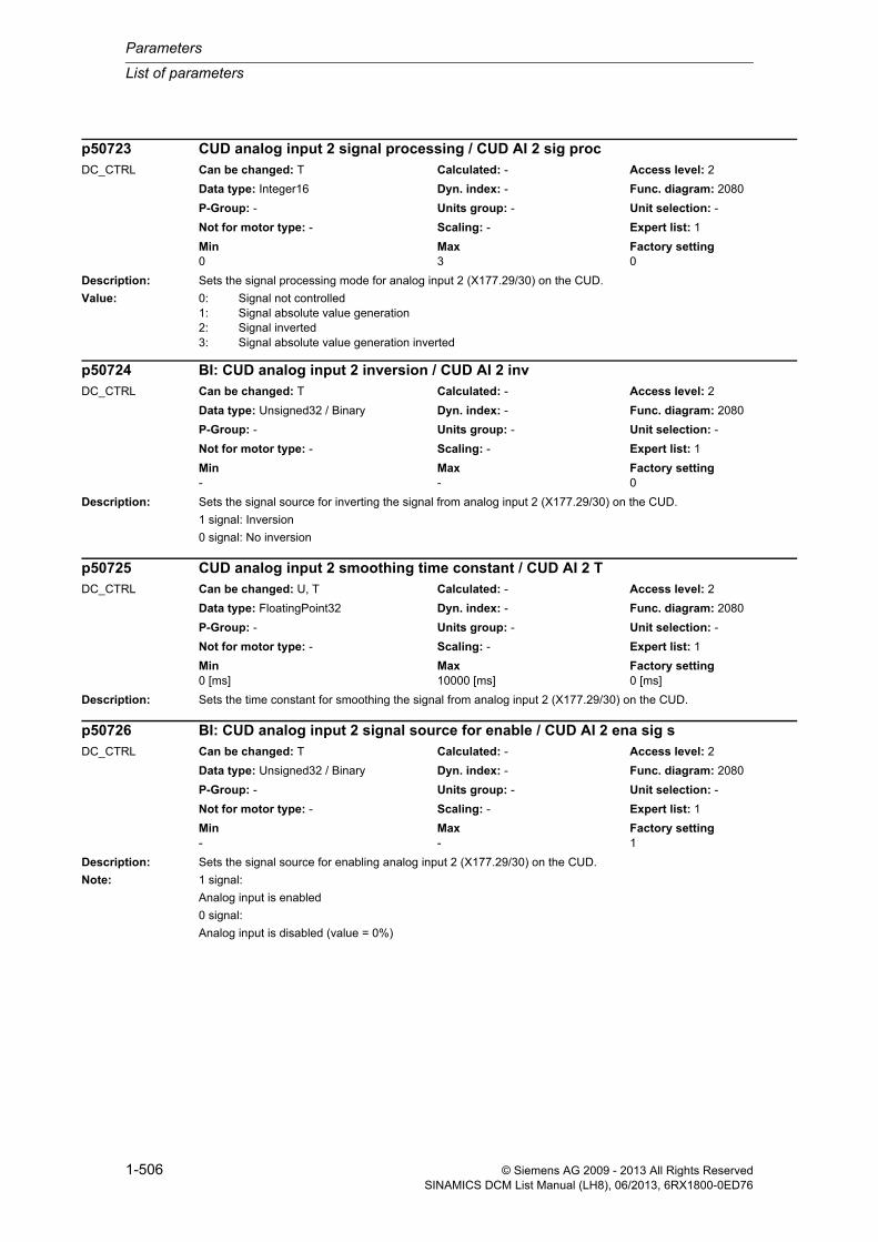
Parameters
List of parameters
1-506 © Siemens AG 2009 - 2013 All Rights ReservedSINAMICS DCM List Manual (LH8), 06/2013, 6RX1800-0ED76
Description: Sets the signal processing mode for analog input 2 (X177.29/30) on the CUD.
Value: 0: Signal not controlled1: Signal absolute value generation2: Signal inverted3: Signal absolute value generation inverted
Description: Sets the signal source for inverting the signal from analog input 2 (X177.29/30) on the CUD.
1 signal: Inversion
0 signal: No inversion
Description: Sets the time constant for smoothing the signal from analog input 2 (X177.29/30) on the CUD.
Description: Sets the signal source for enabling analog input 2 (X177.29/30) on the CUD.
Note: 1 signal:
Analog input is enabled
0 signal:
Analog input is disabled (value = 0%)
p50723 CUD analog input 2 signal processing / CUD AI 2 sig procDC_CTRL Can be changed: T Calculated: - Access level: 2
Data type: Integer16 Dyn. index: - Func. diagram: 2080
P-Group: - Units group: - Unit selection: -
Not for motor type: - Scaling: - Expert list: 1
Min Max Factory setting 0 3 0
p50724 BI: CUD analog input 2 inversion / CUD AI 2 invDC_CTRL Can be changed: T Calculated: - Access level: 2
Data type: Unsigned32 / Binary Dyn. index: - Func. diagram: 2080
P-Group: - Units group: - Unit selection: -
Not for motor type: - Scaling: - Expert list: 1
Min Max Factory setting - - 0
p50725 CUD analog input 2 smoothing time constant / CUD AI 2 TDC_CTRL Can be changed: U, T Calculated: - Access level: 2
Data type: FloatingPoint32 Dyn. index: - Func. diagram: 2080
P-Group: - Units group: - Unit selection: -
Not for motor type: - Scaling: - Expert list: 1
Min Max Factory setting 0 [ms] 10000 [ms] 0 [ms]
p50726 BI: CUD analog input 2 signal source for enable / CUD AI 2 ena sig sDC_CTRL Can be changed: T Calculated: - Access level: 2
Data type: Unsigned32 / Binary Dyn. index: - Func. diagram: 2080
P-Group: - Units group: - Unit selection: -
Not for motor type: - Scaling: - Expert list: 1
Min Max Factory setting - - 1

List of parameters
Parameters
1-507© Siemens AG 2009 - 2013 All Rights ReservedSINAMICS DCM List Manual (LH8), 06/2013, 6RX1800-0ED76
Description: Sets the setpoint for the simulation of analog input 2 (X177.29/30) on the CUD.
Dependency: Refer to: p50729
Note: Simulation is selected using p50729 = 1.
Description: Setting to select the simulation of analog input 2 (X177.29/30) on the CUD.
Value: 0: Simulation deactivated1: Simulation activated
Dependency: Refer to: p50727
Note: The setpoint for the simulation is set in p50727.
Description: Sets the scaling for fast analog inputs "Select input 3 to 6".
The value indicates the percentage value for the mapping of an input voltage of 10 V at the analog input.
Example:
p50731[2] = 90%
--> 10 V is scaled to 90% for select input 5
--> 5 V corresponds to 45% for select input 5
Index: [0] = Select input 3 (X177.1/2)[1] = Select input 4 (X177.3/4)[2] = Select input 5 (X177.5/6)[3] = Select input 6 (X177.7/8)
Note: AI: Analog Input
Description: Sets the offset for fast analog inputs "Select input 3 to 6".
p50727 CUD analog input 2 simulation setpoint / CUD AI 2 sim setpDC_CTRL Can be changed: U, T Calculated: - Access level: 2
Data type: FloatingPoint32 Dyn. index: - Func. diagram: 2080
P-Group: - Units group: - Unit selection: -
Not for motor type: - Scaling: PERCENT Expert list: 1
Min Max Factory setting -130.0 [%] 130.0 [%] 0.0 [%]
p50729 CUD analog input 2 simulation selection / CUD AI 2 sim selDC_CTRL Can be changed: T Calculated: - Access level: 2
Data type: Integer16 Dyn. index: - Func. diagram: 2080
P-Group: - Units group: - Unit selection: -
Not for motor type: - Scaling: - Expert list: 1
Min Max Factory setting 0 1 0
p50731[0...3] Fast analog inputs scaling / Fast AI scalDC_CTRL Can be changed: U, T Calculated: - Access level: 2
Data type: FloatingPoint32 Dyn. index: - Func. diagram: 2085, 2090
P-Group: - Units group: - Unit selection: -
Not for motor type: - Scaling: PERCENT Expert list: 1
Min Max Factory setting -1000.0 [%] 1000.0 [%] 100.0 [%]
p50732[0...3] Fast analog inputs offset / Fast AI offsDC_CTRL Can be changed: U, T Calculated: - Access level: 2
Data type: FloatingPoint32 Dyn. index: - Func. diagram: 2085, 2090
P-Group: - Units group: - Unit selection: -
Not for motor type: - Scaling: PERCENT Expert list: 1
Min Max Factory setting -200.00 [%] 200.00 [%] 0.00 [%]

Parameters
List of parameters
1-508 © Siemens AG 2009 - 2013 All Rights ReservedSINAMICS DCM List Manual (LH8), 06/2013, 6RX1800-0ED76
Index: [0] = Select input 3 (X177.1/2)[1] = Select input 4 (X177.3/4)[2] = Select input 5 (X177.5/6)[3] = Select input 6 (X177.7/8)
Description: Sets the signal processing for fast analog inputs "Select input 3 to 6".
Value: 0: Signal not controlled1: Signal absolute value generation2: Signal inverted3: Signal absolute value generation inverted
Index: [0] = Select input 3 (X177.1/2)[1] = Select input 4 (X177.3/4)[2] = Select input 5 (X177.5/6)[3] = Select input 6 (X177.7/8)
Description: Sets the signal source for inverting the signals for fast analog inputs "Select input 3 to 6".
1 signal: Inversion
0 signal: No inversion
Index: [0] = Select input 3 (X177.1/2)[1] = Select input 4 (X177.3/4)[2] = Select input 5 (X177.5/6)[3] = Select input 6 (X177.7/8)
Description: Sets the time constant for smoothing the signals for fast analog inputs "Select input 3 to 6".
Index: [0] = Select input 3 (X177.1/2)[1] = Select input 4 (X177.3/4)[2] = Select input 5 (X177.5/6)[3] = Select input 6 (X177.7/8)
p50733[0...3] Fast analog inputs signal processing / Fast AI sigDC_CTRL Can be changed: T Calculated: - Access level: 2
Data type: Integer16 Dyn. index: - Func. diagram: 2085, 2090
P-Group: - Units group: - Unit selection: -
Not for motor type: - Scaling: - Expert list: 1
Min Max Factory setting 0 3 0
p50734[0...3] BI: Fast analog inputs inversion / Fast AI invDC_CTRL Can be changed: T Calculated: - Access level: 2
Data type: Unsigned32 / Binary Dyn. index: - Func. diagram: 2085, 2090
P-Group: - Units group: - Unit selection: -
Not for motor type: - Scaling: - Expert list: 1
Min Max Factory setting - - 0
p50735[0...3] Fast analog inputs smoothing time constant / Fast AI TDC_CTRL Can be changed: U, T Calculated: - Access level: 2
Data type: FloatingPoint32 Dyn. index: - Func. diagram: 2085, 2090
P-Group: - Units group: - Unit selection: -
Not for motor type: - Scaling: - Expert list: 1
Min Max Factory setting 0 [ms] 10000 [ms] 0 [ms]

List of parameters
Parameters
1-509© Siemens AG 2009 - 2013 All Rights ReservedSINAMICS DCM List Manual (LH8), 06/2013, 6RX1800-0ED76
Description: Sets the signal source for enabling fast analog inputs "Select input 3 to 6".
Index: [0] = Select input 3 (X177.1/2)[1] = Select input 4 (X177.3/4)[2] = Select input 5 (X177.5/6)[3] = Select input 6 (X177.7/8)
Note: 1 signal:
Analog input is enabled
0 signal:
Analog input is disabled (value = 0%)
Description: Sets the setpoint for the simulation of the fast analog inputs (select input 3 ... 6).
Index: [0] = Select input 3 (X177.1/2)[1] = Select input 4 (X177.3/4)[2] = Select input 5 (X177.5/6)[3] = Select input 6 (X177.7/8)
Dependency: Refer to: p50739
Note: Simulation is selected using p50739[0...3] = 1.
Description: Setting to select the simulation of the fast analog inputs (select input 3 ... 6).
Value: 0: Simulation deactivated1: Simulation activated
Index: [0] = Select input 3 (X177.1/2)[1] = Select input 4 (X177.3/4)[2] = Select input 5 (X177.5/6)[3] = Select input 6 (X177.7/8)
Dependency: Refer to: p50737
Note: The setpoint for the simulation is set in p50737[0...3].
p50736[0...3] BI: Signal source to enable fast analog inputs / Fast AI ena sig sDC_CTRL Can be changed: T Calculated: - Access level: 2
Data type: Unsigned32 / Binary Dyn. index: - Func. diagram: 2085, 2090
P-Group: - Units group: - Unit selection: -
Not for motor type: - Scaling: - Expert list: 1
Min Max Factory setting - - 1
p50737[0...3] Fast analog inputs setpoint simulation / Fast AI sim setpDC_CTRL Can be changed: U, T Calculated: - Access level: 2
Data type: FloatingPoint32 Dyn. index: - Func. diagram: 2085, 2090
P-Group: - Units group: - Unit selection: -
Not for motor type: - Scaling: PERCENT Expert list: 1
Min Max Factory setting -130.0 [%] 130.0 [%] 0.0 [%]
p50739[0...3] Fast analog inputs simulation selection / Fast AI sim selDC_CTRL Can be changed: T Calculated: - Access level: 2
Data type: Integer16 Dyn. index: - Func. diagram: 2085, 2090
P-Group: - Units group: - Unit selection: -
Not for motor type: - Scaling: - Expert list: 1
Min Max Factory setting 0 1 0

Parameters
List of parameters
1-510 © Siemens AG 2009 - 2013 All Rights ReservedSINAMICS DCM List Manual (LH8), 06/2013, 6RX1800-0ED76
Description: Sets the input voltage (8 - 270 V) for scaling to 100%.
Rated value of the input voltage at n_max (= tachometer voltage at maximum speed).
This parameter specifies the maximum speed at p50083 = 1.
Note: AI: Analog Input
Example:
p50741 = 60
--> 30 V is scaled to 50 % for analog input main actual value scaled
--> 60 V is scaled to 100% for analog input main actual value scaled
Description: Sets the offset for the "main actual value" (XT1.103/104).
Description: Sets the mode for signal processing for the "main actual value" analog input (XT1.103/104).
Value: 0: Signal not controlled1: Signal absolute value generation2: Signal inverted3: Signal absolute value generation inverted
Description: Sets the signal source for inverting the signal from the "main actual value" analog input (XT1.103/104).
0 signal: No inversion
1 signal: Inversion
p50741[0...n] Analog input main actual value scaling / AI m act scalDC_CTRL Can be changed: C2(1), U, T Calculated: - Access level: 1
Data type: FloatingPoint32 Dyn. index: DDS, p0180 Func. diagram: 2075
P-Group: - Units group: - Unit selection: -
Not for motor type: - Scaling: - Expert list: 1
Min Max Factory setting -270.00 [V] 270.00 [V] 60.00 [V]
p50742 Analog input main actual value offset / AI m act offsDC_CTRL Can be changed: U, T Calculated: - Access level: 2
Data type: FloatingPoint32 Dyn. index: - Func. diagram: 2075
P-Group: - Units group: - Unit selection: -
Not for motor type: - Scaling: PERCENT Expert list: 1
Min Max Factory setting -200.00 [%] 200.00 [%] 0.00 [%]
p50743 Analog input main actual value signal processing / AI m act sigDC_CTRL Can be changed: T Calculated: - Access level: 2
Data type: Integer16 Dyn. index: - Func. diagram: 2075
P-Group: - Units group: - Unit selection: -
Not for motor type: - Scaling: - Expert list: 1
Min Max Factory setting 0 3 0
p50744 BI: Analog input main actual value inversion / AI m act invDC_CTRL Can be changed: T Calculated: - Access level: 2
Data type: Unsigned32 / Binary Dyn. index: - Func. diagram: 2075
P-Group: - Units group: - Unit selection: -
Not for motor type: - Scaling: - Expert list: 1
Min Max Factory setting - - 0

List of parameters
Parameters
1-511© Siemens AG 2009 - 2013 All Rights ReservedSINAMICS DCM List Manual (LH8), 06/2013, 6RX1800-0ED76
Description: Sets the time constant for smoothing the signal from the "main actual value" analog input (XT1.103/104).
Description: Sets the signal source for enabling the analog input for the "main actual value (XT1.103/104).
Note: 1 signal: Analog input enabled
0 signal: Analog input not enabled (r52013 = 0%).
Description: Sets the setpoint for the simulation of the "main actual value" analog input (XT1.103/104).
Dependency: Refer to: p50749
Note: Simulation is selected using p50749 = 1.
Description: Setting to select the simulation of the "main actual value" analog input (XT1.103/104).
Value: 0: Simulation deactivated1: Simulation activated
Dependency: Refer to: p50747
Note: The setpoint for the simulation is set in p50747.
p50745 Analog input main actual value smoothing time constant / AI m act TDC_CTRL Can be changed: U, T Calculated: - Access level: 2
Data type: FloatingPoint32 Dyn. index: - Func. diagram: 2075
P-Group: - Units group: - Unit selection: -
Not for motor type: - Scaling: - Expert list: 1
Min Max Factory setting 0 [ms] 10000 [ms] 0 [ms]
p50746 BI: Signal source to enable analog input main actual value / AI m act ena sig sDC_CTRL Can be changed: T Calculated: - Access level: 2
Data type: Unsigned32 / Binary Dyn. index: - Func. diagram: 2075
P-Group: - Units group: - Unit selection: -
Not for motor type: - Scaling: - Expert list: 1
Min Max Factory setting - - 1
p50747 Analog input main actual value setpoint simulation / AI m_actV sim setpDC_CTRL Can be changed: U, T Calculated: - Access level: 2
Data type: FloatingPoint32 Dyn. index: - Func. diagram: 2075
P-Group: - Units group: - Unit selection: -
Not for motor type: - Scaling: PERCENT Expert list: 1
Min Max Factory setting -130.0 [%] 130.0 [%] 0.0 [%]
p50749 Analog input main actual value simulation selection / AI m_actV sim selDC_CTRL Can be changed: T Calculated: - Access level: 2
Data type: Integer16 Dyn. index: - Func. diagram: 2075
P-Group: - Units group: - Unit selection: -
Not for motor type: - Scaling: - Expert list: 1
Min Max Factory setting 0 1 0

Parameters
List of parameters
1-512 © Siemens AG 2009 - 2013 All Rights ReservedSINAMICS DCM List Manual (LH8), 06/2013, 6RX1800-0ED76
Description: Sets the signal source for the output value at analog output 0 (X177.49/50).
Note: AO: Analog Output
Description: Sets the mode for signal processing at analog output 0 (X177.49/50).
Value: 0: Signal not controlled1: Signal absolute value generation2: Signal inverted3: Signal absolute value generation inverted
Description: Sets the time constant for smoothing the signal from analog output 0 (X177.49/50).
Description: Sets the scaling for analog output 0 (X177.49/50).
The value indicates the output value for the mapping of an input value of 100% at the analog output.
Note: Example:
p50753 = 5 V
--> 100% is scaled to 5 V
--> 50% corresponds to 2.5 V
p50750 CI: CUD analog output 0 signal source / CUD AO 0 sig sDC_CTRL Can be changed: U, T Calculated: - Access level: 2
Data type: Unsigned32 / FloatingPoint32 Dyn. index: - Func. diagram: 2095
P-Group: - Units group: - Unit selection: -
Not for motor type: - Scaling: PERCENT Expert list: 1
Min Max Factory setting - - 0
p50751 CUD analog output 0 signal processing / CUD AO 0 sig procDC_CTRL Can be changed: U, T Calculated: - Access level: 2
Data type: Integer16 Dyn. index: - Func. diagram: 2095
P-Group: - Units group: - Unit selection: -
Not for motor type: - Scaling: - Expert list: 1
Min Max Factory setting 0 3 0
p50752 CUD analog output 0 smoothing time constant / CUD AO 0 TDC_CTRL Can be changed: U, T Calculated: - Access level: 2
Data type: FloatingPoint32 Dyn. index: - Func. diagram: 2095
P-Group: - Units group: - Unit selection: -
Not for motor type: - Scaling: - Expert list: 1
Min Max Factory setting 0 [ms] 10000 [ms] 0 [ms]
p50753 CUD analog output 0 scaling / CUD AO 0 scalDC_CTRL Can be changed: U, T Calculated: - Access level: 2
Data type: FloatingPoint32 Dyn. index: - Func. diagram: 2095
P-Group: - Units group: - Unit selection: -
Not for motor type: - Scaling: - Expert list: 1
Min Max Factory setting -200.00 [V] 200.00 [V] 10.00 [V]
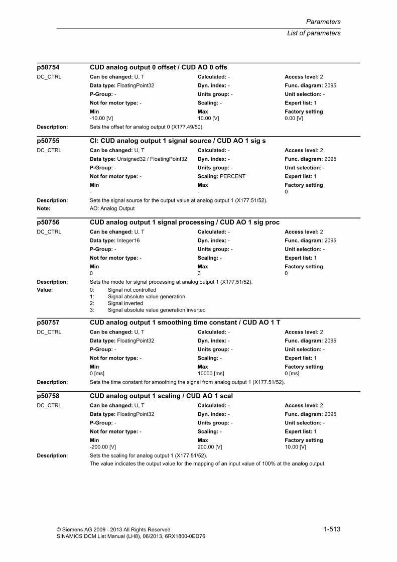
List of parameters
Parameters
1-513© Siemens AG 2009 - 2013 All Rights ReservedSINAMICS DCM List Manual (LH8), 06/2013, 6RX1800-0ED76
Description: Sets the offset for analog output 0 (X177.49/50).
Description: Sets the signal source for the output value at analog output 1 (X177.51/52).
Note: AO: Analog Output
Description: Sets the mode for signal processing at analog output 1 (X177.51/52).
Value: 0: Signal not controlled1: Signal absolute value generation2: Signal inverted3: Signal absolute value generation inverted
Description: Sets the time constant for smoothing the signal from analog output 1 (X177.51/52).
Description: Sets the scaling for analog output 1 (X177.51/52).
The value indicates the output value for the mapping of an input value of 100% at the analog output.
p50754 CUD analog output 0 offset / CUD AO 0 offsDC_CTRL Can be changed: U, T Calculated: - Access level: 2
Data type: FloatingPoint32 Dyn. index: - Func. diagram: 2095
P-Group: - Units group: - Unit selection: -
Not for motor type: - Scaling: - Expert list: 1
Min Max Factory setting -10.00 [V] 10.00 [V] 0.00 [V]
p50755 CI: CUD analog output 1 signal source / CUD AO 1 sig sDC_CTRL Can be changed: U, T Calculated: - Access level: 2
Data type: Unsigned32 / FloatingPoint32 Dyn. index: - Func. diagram: 2095
P-Group: - Units group: - Unit selection: -
Not for motor type: - Scaling: PERCENT Expert list: 1
Min Max Factory setting - - 0
p50756 CUD analog output 1 signal processing / CUD AO 1 sig procDC_CTRL Can be changed: U, T Calculated: - Access level: 2
Data type: Integer16 Dyn. index: - Func. diagram: 2095
P-Group: - Units group: - Unit selection: -
Not for motor type: - Scaling: - Expert list: 1
Min Max Factory setting 0 3 0
p50757 CUD analog output 1 smoothing time constant / CUD AO 1 TDC_CTRL Can be changed: U, T Calculated: - Access level: 2
Data type: FloatingPoint32 Dyn. index: - Func. diagram: 2095
P-Group: - Units group: - Unit selection: -
Not for motor type: - Scaling: - Expert list: 1
Min Max Factory setting 0 [ms] 10000 [ms] 0 [ms]
p50758 CUD analog output 1 scaling / CUD AO 1 scalDC_CTRL Can be changed: U, T Calculated: - Access level: 2
Data type: FloatingPoint32 Dyn. index: - Func. diagram: 2095
P-Group: - Units group: - Unit selection: -
Not for motor type: - Scaling: - Expert list: 1
Min Max Factory setting -200.00 [V] 200.00 [V] 10.00 [V]

Parameters
List of parameters
1-514 © Siemens AG 2009 - 2013 All Rights ReservedSINAMICS DCM List Manual (LH8), 06/2013, 6RX1800-0ED76
Note: Example:
p50758 = 5 V
--> 100% is scaled to 5 V
--> 50% corresponds to 2.5 V
Description: Sets the offset for analog output 1 (X177.51/52).
Description: Setting to select the simulation of the digital inputs on the CUD.
Dependency: Refer to: p50766
Note: The setpoint for the simulation is set in p50766.0...7.
Description: Sets the setpoint for the simulation of the digital inputs on the CUD.
Dependency: Refer to: p50765
Note: Simulation is selected using p50765.0...7 = 1.
p50759 CUD analog output 1 offset / CUD AO 1 offsDC_CTRL Can be changed: U, T Calculated: - Access level: 2
Data type: FloatingPoint32 Dyn. index: - Func. diagram: 2095
P-Group: - Units group: - Unit selection: -
Not for motor type: - Scaling: - Expert list: 1
Min Max Factory setting -10.00 [V] 10.00 [V] 0.00 [V]
p50765 CUD digital inputs simulation selection / CUD DI sim selDC_CTRL Can be changed: U, T Calculated: - Access level: 2
Data type: Unsigned16 Dyn. index: - Func. diagram: 2050, 2060, 2065
P-Group: - Units group: - Unit selection: -
Not for motor type: - Scaling: - Expert list: 1
Min Max Factory setting - - 0000 0000 bin
Bit field: Bit Signal name 1 signal 0 signal FP00 DI 0 (X177.11) High Low 205001 DI 1 (X177.12) High Low 205002 DI 2 (X177.13) High Low 205003 DI 3 (X177.14) High Low 205004 DI 4 (X177.15) High Low 206005 DI 5 (X177.16) High Low 206006 DI 6 (X177.17) High Low 206507 DI 7 (X177.18) High Low 2065
p50766 CUD digital inputs simulation setpoint / CUD DI simul setpDC_CTRL Can be changed: U, T Calculated: - Access level: 2
Data type: Unsigned16 Dyn. index: - Func. diagram: 2050, 2060, 2065
P-Group: - Units group: - Unit selection: -
Not for motor type: - Scaling: - Expert list: 1
Min Max Factory setting - - 0000 0000 bin
Bit field: Bit Signal name 1 signal 0 signal FP00 DI 0 (X177.11) High Low 205001 DI 1 (X177.12) High Low 205002 DI 2 (X177.13) High Low 205003 DI 3 (X177.14) High Low 205004 DI 4 (X177.15) High Low 206005 DI 5 (X177.16) High Low 206006 DI 6 (X177.17) High Low 206507 DI 7 (X177.18) High Low 2065
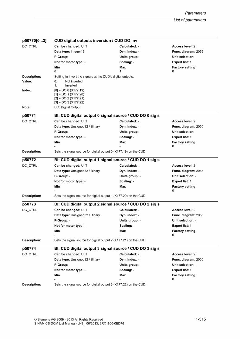
List of parameters
Parameters
1-515© Siemens AG 2009 - 2013 All Rights ReservedSINAMICS DCM List Manual (LH8), 06/2013, 6RX1800-0ED76
Description: Setting to invert the signals at the CUD's digital outputs.
Value: 0: Not inverted1: Inverted
Index: [0] = DO 0 (X177.19)[1] = DO 1 (X177.20)[2] = DO 2 (X177.21)[3] = DO 3 (X177.22)
Note: DO: Digital Output
Description: Sets the signal source for digital output 0 (X177.19) on the CUD.
Description: Sets the signal source for digital output 1 (X177.20) on the CUD.
Description: Sets the signal source for digital output 2 (X177.21) on the CUD.
Description: Sets the signal source for digital output 3 (X177.22) on the CUD.
p50770[0...3] CUD digital outputs inversion / CUD DO invDC_CTRL Can be changed: U, T Calculated: - Access level: 2
Data type: Integer16 Dyn. index: - Func. diagram: 2055
P-Group: - Units group: - Unit selection: -
Not for motor type: - Scaling: - Expert list: 1
Min Max Factory setting 0 1 0
p50771 BI: CUD digital output 0 signal source / CUD DO 0 sig sDC_CTRL Can be changed: U, T Calculated: - Access level: 2
Data type: Unsigned32 / Binary Dyn. index: - Func. diagram: 2055
P-Group: - Units group: - Unit selection: -
Not for motor type: - Scaling: - Expert list: 1
Min Max Factory setting - - 0
p50772 BI: CUD digital output 1 signal source / CUD DO 1 sig sDC_CTRL Can be changed: U, T Calculated: - Access level: 2
Data type: Unsigned32 / Binary Dyn. index: - Func. diagram: 2055
P-Group: - Units group: - Unit selection: -
Not for motor type: - Scaling: - Expert list: 1
Min Max Factory setting - - 0
p50773 BI: CUD digital output 2 signal source / CUD DO 2 sig sDC_CTRL Can be changed: U, T Calculated: - Access level: 2
Data type: Unsigned32 / Binary Dyn. index: - Func. diagram: 2055
P-Group: - Units group: - Unit selection: -
Not for motor type: - Scaling: - Expert list: 1
Min Max Factory setting - - 0
p50774 BI: CUD digital output 3 signal source / CUD DO 3 sig sDC_CTRL Can be changed: U, T Calculated: - Access level: 2
Data type: Unsigned32 / Binary Dyn. index: - Func. diagram: 2055
P-Group: - Units group: - Unit selection: -
Not for motor type: - Scaling: - Expert list: 1
Min Max Factory setting - - 0

Parameters
List of parameters
1-516 © Siemens AG 2009 - 2013 All Rights ReservedSINAMICS DCM List Manual (LH8), 06/2013, 6RX1800-0ED76
Description: Sets the delay time for digital output 0 (X177.19) on the CUD.
Note: The level at the digital output can only change if the changed internal level remains constant for longer than the set delay time.
Description: Sets the delay time for digital output 1 (X177.20) on the CUD.
Note: The level at the digital output can only change if the changed internal level remains constant for longer than the set delay time.
Description: Sets the delay time for digital output 2 (X177.21) on the CUD.
Note: The level at the digital output can only change if the changed internal level remains constant for longer than the set delay time.
Description: Sets the delay time for digital output 3 (X177.22) on the CUD.
Note: The level at the digital output can only change if the changed internal level remains constant for longer than the set delay time.
Description: Setting to invert the signals at the CUD's digital outputs.
p50775 CUD digital output 0 delay time / CUD DO 0 t_delDC_CTRL Can be changed: U, T Calculated: - Access level: 2
Data type: FloatingPoint32 Dyn. index: - Func. diagram: 2055
P-Group: - Units group: - Unit selection: -
Not for motor type: - Scaling: - Expert list: 1
Min Max Factory setting 0 [ms] 10000 [ms] 0 [ms]
p50776 CUD digital output 1 delay time / CUD DO 1 t_delDC_CTRL Can be changed: U, T Calculated: - Access level: 2
Data type: FloatingPoint32 Dyn. index: - Func. diagram: 2055
P-Group: - Units group: - Unit selection: -
Not for motor type: - Scaling: - Expert list: 1
Min Max Factory setting 0 [ms] 10000 [ms] 0 [ms]
p50777 CUD digital output 2 delay time / CUD DO 2 t_delDC_CTRL Can be changed: U, T Calculated: - Access level: 2
Data type: FloatingPoint32 Dyn. index: - Func. diagram: 2055
P-Group: - Units group: - Unit selection: -
Not for motor type: - Scaling: - Expert list: 1
Min Max Factory setting 0 [ms] 10000 [ms] 0 [ms]
p50778 CUD digital output 3 delay time / CUD DO 3 t_delDC_CTRL Can be changed: U, T Calculated: - Access level: 2
Data type: FloatingPoint32 Dyn. index: - Func. diagram: 2055
P-Group: - Units group: - Unit selection: -
Not for motor type: - Scaling: - Expert list: 1
Min Max Factory setting 0 [ms] 10000 [ms] 0 [ms]
p50780[0...3] CUD digital inputs/outputs inversion / CUD DI/DO invDC_CTRL Can be changed: U, T Calculated: - Access level: 2
Data type: Integer16 Dyn. index: - Func. diagram: 2060, 2065
P-Group: - Units group: - Unit selection: -
Not for motor type: - Scaling: - Expert list: 1
Min Max Factory setting 0 1 0

List of parameters
Parameters
1-517© Siemens AG 2009 - 2013 All Rights ReservedSINAMICS DCM List Manual (LH8), 06/2013, 6RX1800-0ED76
Value: 0: Not inverted1: Inverted
Index: [0] = DI/DO 4 (X177.15)[1] = DI/DO 5 (X177.16)[2] = DI/DO 6 (X177.17)[3] = DI/DO 7 (X177.18)
Dependency: The terminal must be set as an output (p50789[0 to 3]).
Refer to: p50789
Note: DI/DO: Bidirectional Digital Input/Output
Description: Sets the signal source for digital input/output 4 (X177.15) on the CUD.
Dependency: The terminal must be set as an output (p50789[0] = 1).
Refer to: p50789
Description: Sets the signal source for digital input/output 5 (X177.16) on the CUD.
Dependency: The terminal must be set as an output (p50789[1] = 1).
Refer to: p50789
Description: Sets the signal source for digital input/output 6 (X177.17) on the CUD.
Dependency: The terminal must be set as an output (p50789[2] = 1).
Refer to: p50789
Description: Sets the signal source for digital input/output 7 (X177.18) on the CUD.
Dependency: The terminal must be set as an output (p50789[3] = 1).
Refer to: p50789
p50781 BI: CUD digital input/output 4 signal source / CUD DI/DO 4 sig sDC_CTRL Can be changed: U, T Calculated: - Access level: 2
Data type: Unsigned32 / Binary Dyn. index: - Func. diagram: 2060
P-Group: - Units group: - Unit selection: -
Not for motor type: - Scaling: - Expert list: 1
Min Max Factory setting - - 0
p50782 BI: CUD digital input/output 5 signal source / CUD DI/DO 5 sig sDC_CTRL Can be changed: U, T Calculated: - Access level: 2
Data type: Unsigned32 / Binary Dyn. index: - Func. diagram: 2060
P-Group: - Units group: - Unit selection: -
Not for motor type: - Scaling: - Expert list: 1
Min Max Factory setting - - 0
p50783 BI: CUD digital input/output 6 signal source / CUD DI/DO 6 sig sDC_CTRL Can be changed: U, T Calculated: - Access level: 2
Data type: Unsigned32 / Binary Dyn. index: - Func. diagram: 2065
P-Group: - Units group: - Unit selection: -
Not for motor type: - Scaling: - Expert list: 1
Min Max Factory setting - - 0
p50784 BI: CUD digital input/output 7 signal source / CUD DI/DO 7 sig sDC_CTRL Can be changed: U, T Calculated: - Access level: 2
Data type: Unsigned32 / Binary Dyn. index: - Func. diagram: 2065
P-Group: - Units group: - Unit selection: -
Not for motor type: - Scaling: - Expert list: 1
Min Max Factory setting - - 0

Parameters
List of parameters
1-518 © Siemens AG 2009 - 2013 All Rights ReservedSINAMICS DCM List Manual (LH8), 06/2013, 6RX1800-0ED76
Description: Sets the delay time for digital input/output 4 (X177.15) on the CUD.
Dependency: The terminal must be set as an output (p50789[0] = 1).
Refer to: p50789
Note: The level at the digital output can only change if the changed internal level remains constant for longer than the set delay time.
Description: Sets the delay time for digital input/output 5 (X177.16) on the CUD.
Dependency: The terminal must be set as an output (p50789[1] = 1).
Refer to: p50789
Note: The level at the digital output can only change if the changed internal level remains constant for longer than the set delay time.
Description: Sets the delay time for digital input/output 6 (X177.17) on the CUD.
Dependency: The terminal must be set as an output (p50789[2] = 1).
Refer to: p50789
Note: The level at the digital output can only change if the changed internal level remains constant for longer than the set delay time.
Description: Sets the delay time for digital input/output 7 (X177.18) on the CUD.
Dependency: The terminal must be set as an output (p50789[3] = 1).
Refer to: p50789
Note: The level at the digital output can only change if the changed internal level remains constant for longer than the set delay time.
p50785 CUD digital input/output 4 delay time / CUD DI/DO 4 t_delDC_CTRL Can be changed: U, T Calculated: - Access level: 2
Data type: FloatingPoint32 Dyn. index: - Func. diagram: 2060
P-Group: - Units group: - Unit selection: -
Not for motor type: - Scaling: - Expert list: 1
Min Max Factory setting 0 [ms] 10000 [ms] 0 [ms]
p50786 CUD digital input/output 5 delay time / CUD DI/DO 5 t_delDC_CTRL Can be changed: U, T Calculated: - Access level: 2
Data type: FloatingPoint32 Dyn. index: - Func. diagram: 2060
P-Group: - Units group: - Unit selection: -
Not for motor type: - Scaling: - Expert list: 1
Min Max Factory setting 0 [ms] 10000 [ms] 0 [ms]
p50787 CUD digital input/output 6 delay time / CUD DI/DO 6 t_delDC_CTRL Can be changed: U, T Calculated: - Access level: 2
Data type: FloatingPoint32 Dyn. index: - Func. diagram: 2065
P-Group: - Units group: - Unit selection: -
Not for motor type: - Scaling: - Expert list: 1
Min Max Factory setting 0 [ms] 10000 [ms] 0 [ms]
p50788 CUD digital input/output 7 delay time / CUD DI/DO 7 t_delDC_CTRL Can be changed: U, T Calculated: - Access level: 2
Data type: FloatingPoint32 Dyn. index: - Func. diagram: 2065
P-Group: - Units group: - Unit selection: -
Not for motor type: - Scaling: - Expert list: 1
Min Max Factory setting 0 [ms] 10000 [ms] 0 [ms]

List of parameters
Parameters
1-519© Siemens AG 2009 - 2013 All Rights ReservedSINAMICS DCM List Manual (LH8), 06/2013, 6RX1800-0ED76
Description: Sets the type for the digital inputs/outputs on the CUD.
Value: 0: Input1: Output
Index: [0] = DI/DO 4 (X177.15)[1] = DI/DO 5 (X177.16)[2] = DI/DO 6 (X177.17)[3] = DI/DO 7 (X177.18)
Note: DI/DO: Bidirectional Digital Input/Output
Description: Sets the operating mode for the peer-to-peer interface (P2P IF).
Value: 0: No function5: Peer-to-peer communication6: Communication with SIMOREG CCP
Note: P2P IF: Peer-to-peer interface
CCP: Converter Commutation Protector
Description: Sets the number of words to be transmitted for the peer-to-peer interface (P2P IF) in "Peer-to-peer communication" mode (p50790 = 5).
Dependency: Refer to: p50790
Description: Sets the baud rate for the peer-to-peer interface (P2P IF).
Value: 1: 300 baud2: 600 baud3: 1200 baud4: 2400 baud
p50789[0...3] CUD digital inputs/outputs type / CUD DI/DO typDC_CTRL Can be changed: T Calculated: - Access level: 2
Data type: Integer16 Dyn. index: - Func. diagram: 2060, 2065
P-Group: - Units group: - Unit selection: -
Not for motor type: - Scaling: - Expert list: 1
Min Max Factory setting 0 1 0
p50790 P2P IF operating mode / P2P op modeDC_CTRL Can be changed: T Calculated: - Access level: 2
Data type: Integer16 Dyn. index: - Func. diagram: 9300
P-Group: - Units group: - Unit selection: -
Not for motor type: - Scaling: - Expert list: 1
Min Max Factory setting 0 6 0
p50791 P2P IF number of data words / P2P num wordsDC_CTRL Can be changed: T Calculated: - Access level: 2
Data type: Unsigned16 Dyn. index: - Func. diagram: 9300
P-Group: - Units group: - Unit selection: -
Not for motor type: - Scaling: - Expert list: 1
Min Max Factory setting 1 5 5
p50793 P2P IF baud rate / P2P baud rateDC_CTRL Can be changed: T Calculated: - Access level: 2
Data type: Integer16 Dyn. index: - Func. diagram: 9300
P-Group: - Units group: - Unit selection: -
Not for motor type: - Scaling: - Expert list: 1
Min Max Factory setting 1 13 13

Parameters
List of parameters
1-520 © Siemens AG 2009 - 2013 All Rights ReservedSINAMICS DCM List Manual (LH8), 06/2013, 6RX1800-0ED76
5: 4800 baud6: 9600 baud7: 19200 baud8: 38400 baud9: 56700 baud11: 93750 baud13: 187500 baud
Description: Sets the signal source for the data to be transmitted on the peer-to-peer interface (P2P IF).
The transmit data is displayed in r50813[0 to 4].
Index: [0] = Word 1[1] = Word 2[2] = Word 3[3] = Word 4[4] = Word 5
Dependency: Refer to: r50813
Description: Sets the bus terminator for the peer-to-peer interface and the interface to the SIMOREG CCP.
Value: 0: OFF1: ON
Note: CCP: Converter Commutation Protector
P2P: Peer-to-Peer interface
Description: Sets the telegram monitoring time for the peer-to-peer interface (P2P IF).
The time set is only effective in "Peer-to-peer interface" operating mode (p50790 = 5).
p50797 = 0:
Monitoring is de-activated.
p50797 > 0:
Monitoring is activated.
As well as one valid telegram being received, the next valid telegram must be received within the set time. Other-wise, fault F60012 is triggered.
p50794[0...4] CI: P2P IF transmit data signal source / P2P tr data sig sDC_CTRL Can be changed: U, T Calculated: - Access level: 2
Data type: Unsigned32 / Integer16 Dyn. index: - Func. diagram: 9300
P-Group: - Units group: - Unit selection: -
Not for motor type: - Scaling: 4000H Expert list: 1
Min Max Factory setting - - 0
p50795 P2P/CCP bus terminator / P2P/CCP bus termDC_CTRL Can be changed: T Calculated: - Access level: 2
Data type: Integer16 Dyn. index: - Func. diagram: 6970, 9300
P-Group: - Units group: - Unit selection: -
Not for motor type: - Scaling: - Expert list: 1
Min Max Factory setting 0 1 0
p50797 P2P IF telegram monitoring time / P2P t_telegr monDC_CTRL Can be changed: T Calculated: - Access level: 2
Data type: FloatingPoint32 Dyn. index: - Func. diagram: 9300
P-Group: - Units group: - Unit selection: -
Not for motor type: - Scaling: - Expert list: 1
Min Max Factory setting 0.000 [s] 65.000 [s] 0.000 [s]

List of parameters
Parameters
1-521© Siemens AG 2009 - 2013 All Rights ReservedSINAMICS DCM List Manual (LH8), 06/2013, 6RX1800-0ED76
Note: Telegram monitoring is activated in the following cases:
- From receipt of the first error-free telegram
- After switching on of the electronics power supply
- From receipt of the first error-free telegram after telegram monitoring has responded (i.e. telegram monitoring timeout).
The telegram monitoring time (p50797) depends on the baud rate set (p50793) The following minimum setting val-ues are recommended for safe operation:
- 300 baud --> p50797 = 0.520 s (recommended minimum value)
- 600 baud --> p50797 = 0.260 s (recommended minimum value)
- 1200 baud --> p50797 = 0.140 s (recommended minimum value)
- 2400 baud --> p50797 = 0.080 s (recommended minimum value)
- 4800 baud --> p50797 = 0.040 s (recommended minimum value)
If the "Automatic restart" function (p50086b > 0) has been selected on the peer-to-peer communication partner, only a parameter setting p50797 > p50086 (on the communication partner) will be meaningful.
Description: Sets the signal source for triggering fault F60012 "Telegram monitoring timeout".
Description: Displays the diagnostic information for the peer-to-peer interface and the interface to SIMOREG CCP.
Index: [0] = Number of error-free telegrams[1] = Number of erroneous telegrams[2] = Number of byte frame errors[3] = Number of overrun errors[4] = Number of parity errors[5] = Number of STX errors[6] = Number of block check errors[7] = Number of break errors[8] = Number of timeout errors
Note: The fault frequency is recorded with free-running counters; when a counter reaches 65535 it is reset to 0.
The diagnostic information in indexes 5, 6 and 8 is irrelevant for communication with SIMOREG CCP (p50790 = 6).
Possible causes for STX errors:
- Non-observance of start interval before STX
- STX incorrect, i.e. not equal to 02
Possible causes for timeout errors:
- Telegram monitoring timeout (p50797)
p50798 BI: P2P IF signal source for triggering F60012 / P2P F60012 sig sDC_CTRL Can be changed: T Calculated: - Access level: 2
Data type: Unsigned32 / Binary Dyn. index: - Func. diagram: 9300
P-Group: - Units group: - Unit selection: -
Not for motor type: - Scaling: - Expert list: 1
Min Max Factory setting - - 53300.0
r50799[0...8] P2P/CCP diagnostics / P2P/CCP diagDC_CTRL Can be changed: - Calculated: - Access level: 1
Data type: Unsigned16 Dyn. index: - Func. diagram: 6970, 9300
P-Group: - Units group: - Unit selection: -
Not for motor type: - Scaling: - Expert list: 1
Min Max Factory setting - - -

Parameters
List of parameters
1-522 © Siemens AG 2009 - 2013 All Rights ReservedSINAMICS DCM List Manual (LH8), 06/2013, 6RX1800-0ED76
Description: Displays the transmit data for the peer-to-peer interface (P2P IF).
The signal source for the data to be transmitted is set via connector input p50794[0 to 4].
Index: [0] = Word 1[1] = Word 2[2] = Word 3[3] = Word 4[4] = Word 5
Dependency: Refer to: p50794
Description: Sets the signal source to enable data to be received on the peer-to-peer interface (P2P IF).
1 signal: Data receive enabled
0 signal: Data receive not enabled
Description: Sets the signal source to enable data to be transmitted on the peer-to-peer interface (P2P IF).
1 signal: Data transmission enabled
0 signal: Data transmission not enabled
Description: Sets the bus terminator for the RS485 interface (PPI/USS, X178).
Value: 0: OFF1: ON
r50813[0...4] P2P IF transmit data display / P2P tr data dispDC_CTRL Can be changed: - Calculated: - Access level: 1
Data type: Unsigned16 Dyn. index: - Func. diagram: 9300
P-Group: - Units group: - Unit selection: -
Not for motor type: - Scaling: - Expert list: 1
Min Max Factory setting - - -
p50816 BI: P2P IF receive enable signal source / P2P recv ena sig sDC_CTRL Can be changed: T Calculated: - Access level: 2
Data type: Unsigned32 / Binary Dyn. index: - Func. diagram: 9300
P-Group: - Units group: - Unit selection: -
Not for motor type: - Scaling: - Expert list: 1
Min Max Factory setting - - 1
p50817 BI: P2P IF transmit enable signal source / P2P tr ena sig sDC_CTRL Can be changed: T Calculated: - Access level: 2
Data type: Unsigned32 / Binary Dyn. index: - Func. diagram: 9300
P-Group: - Units group: - Unit selection: -
Not for motor type: - Scaling: - Expert list: 1
Min Max Factory setting - - 1
p50820 PPI/USS bus terminator / PPI/USS bus termDC_CTRL Can be changed: U, T Calculated: - Access level: 1
Data type: Integer16 Dyn. index: - Func. diagram: 2410
P-Group: - Units group: - Unit selection: -
Not for motor type: - Scaling: - Expert list: 1
Min Max Factory setting 0 1 1

List of parameters
Parameters
1-523© Siemens AG 2009 - 2013 All Rights ReservedSINAMICS DCM List Manual (LH8), 06/2013, 6RX1800-0ED76
Description: Displays the voltages for the electronic power supply.
Index: [0] = P10 (+10 V)[1] = N10 (-10 V)
Dependency: Refer to: r50824
Note: For r50823[0]:
A voltage value outside the permissible limits will trigger fault F60091.
For r50823[1]:
A voltage value outside the permissible limits will trigger fault F60092.
Description: Displays the failure duration for the electronic power supply.
Dependency: Refer to: r50823
Description: Displays the compensation values for the armature power unit.
Description: Displays the compensation values for the field power unit.
r50823[0...1] Electronic power supply voltage display / Electr supp V dispDC_CTRL Can be changed: - Calculated: - Access level: 1
Data type: FloatingPoint32 Dyn. index: - Func. diagram: 8048
P-Group: - Units group: - Unit selection: -
Not for motor type: - Scaling: p2001 Expert list: 1
Min Max Factory setting - [V] - [V] - [V]
r50824 Electronic power supply failure duration / Electr supp t_failDC_CTRL Can be changed: - Calculated: - Access level: 1
Data type: FloatingPoint32 Dyn. index: - Func. diagram: 8048
P-Group: - Units group: - Unit selection: -
Not for motor type: - Scaling: - Expert list: 1
Min Max Factory setting - [ms] - [ms] - [ms]
r50825[0...29] Armature power unit compensation values / PU arm comp valDC_CTRL Can be changed: - Calculated: - Access level: 4
Data type: FloatingPoint32 Dyn. index: - Func. diagram: 8054
P-Group: - Units group: - Unit selection: -
Not for motor type: - Scaling: - Expert list: 1
Min Max Factory setting - - -
r50826[0...15] Field power unit compensation values / PU field comp valDC_CTRL Can be changed: - Calculated: - Access level: 4
Data type: FloatingPoint32 Dyn. index: - Func. diagram: 8054
P-Group: - Units group: - Unit selection: -
Not for motor type: - Scaling: - Expert list: 1
Min Max Factory setting - - -

Parameters
List of parameters
1-524 © Siemens AG 2009 - 2013 All Rights ReservedSINAMICS DCM List Manual (LH8), 06/2013, 6RX1800-0ED76
Description: Displays the counter reading for internal errors.
Description: Displays the compensation values for the analog inputs/outputs on the Control Unit DC MASTER (CUD).
r50827 Internal diagnostics / Int diagDC_CTRL Can be changed: - Calculated: - Access level: 4
Data type: Unsigned16 Dyn. index: - Func. diagram: 8060
P-Group: - Units group: - Unit selection: -
Not for motor type: - Scaling: - Expert list: 1
Min Max Factory setting - - -
r50829[0...55] CUD compensation values / CUD comp valDC_CTRL Can be changed: - Calculated: - Access level: 4
Data type: Unsigned16 Dyn. index: - Func. diagram: 8054
P-Group: - Units group: - Unit selection: -
Not for motor type: - Scaling: - Expert list: 1
Min Max Factory setting - - -
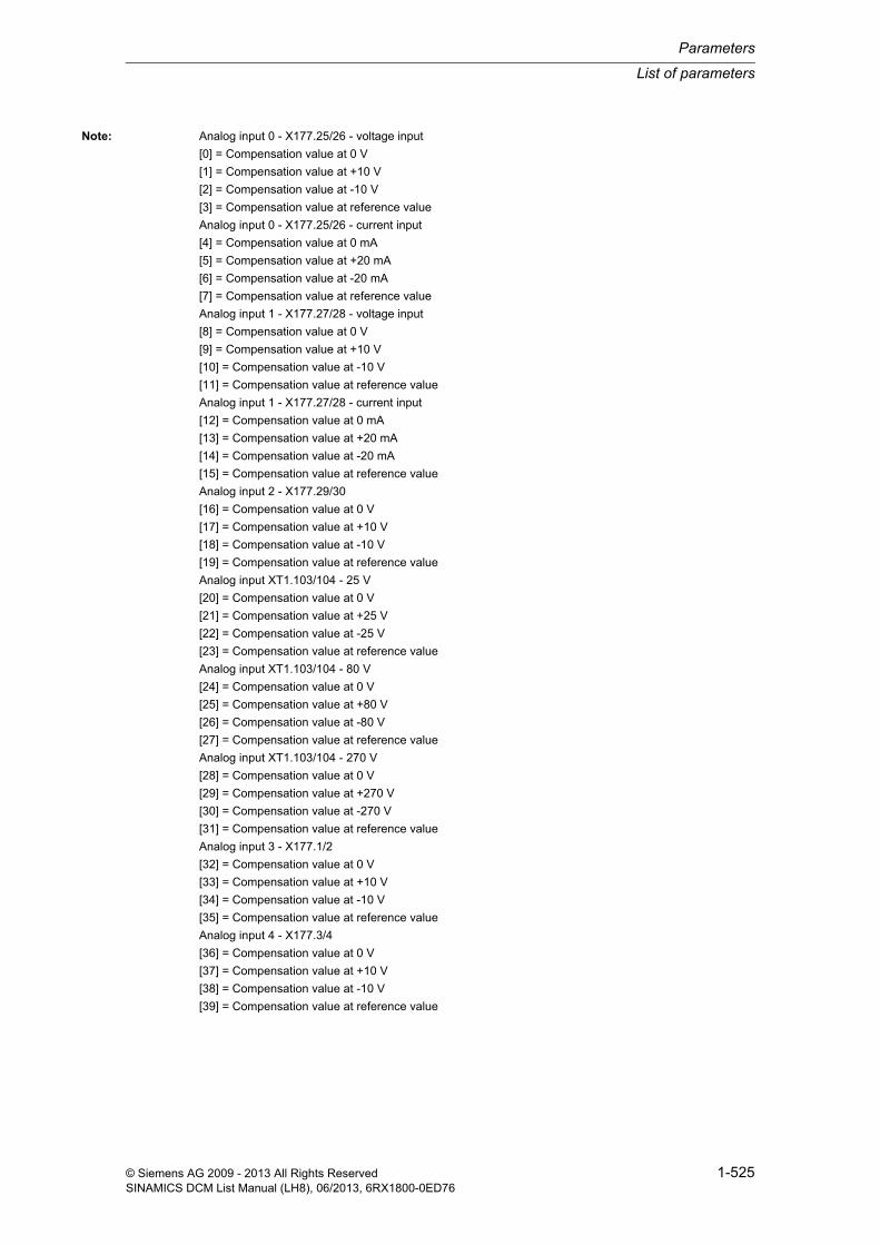
List of parameters
Parameters
1-525© Siemens AG 2009 - 2013 All Rights ReservedSINAMICS DCM List Manual (LH8), 06/2013, 6RX1800-0ED76
Note: Analog input 0 - X177.25/26 - voltage input
[0] = Compensation value at 0 V
[1] = Compensation value at +10 V
[2] = Compensation value at -10 V
[3] = Compensation value at reference value
Analog input 0 - X177.25/26 - current input
[4] = Compensation value at 0 mA
[5] = Compensation value at +20 mA
[6] = Compensation value at -20 mA
[7] = Compensation value at reference value
Analog input 1 - X177.27/28 - voltage input
[8] = Compensation value at 0 V
[9] = Compensation value at +10 V
[10] = Compensation value at -10 V
[11] = Compensation value at reference value
Analog input 1 - X177.27/28 - current input
[12] = Compensation value at 0 mA
[13] = Compensation value at +20 mA
[14] = Compensation value at -20 mA
[15] = Compensation value at reference value
Analog input 2 - X177.29/30
[16] = Compensation value at 0 V
[17] = Compensation value at +10 V
[18] = Compensation value at -10 V
[19] = Compensation value at reference value
Analog input XT1.103/104 - 25 V
[20] = Compensation value at 0 V
[21] = Compensation value at +25 V
[22] = Compensation value at -25 V
[23] = Compensation value at reference value
Analog input XT1.103/104 - 80 V
[24] = Compensation value at 0 V
[25] = Compensation value at +80 V
[26] = Compensation value at -80 V
[27] = Compensation value at reference value
Analog input XT1.103/104 - 270 V
[28] = Compensation value at 0 V
[29] = Compensation value at +270 V
[30] = Compensation value at -270 V
[31] = Compensation value at reference value
Analog input 3 - X177.1/2
[32] = Compensation value at 0 V
[33] = Compensation value at +10 V
[34] = Compensation value at -10 V
[35] = Compensation value at reference value
Analog input 4 - X177.3/4
[36] = Compensation value at 0 V
[37] = Compensation value at +10 V
[38] = Compensation value at -10 V
[39] = Compensation value at reference value

Parameters
List of parameters
1-526 © Siemens AG 2009 - 2013 All Rights ReservedSINAMICS DCM List Manual (LH8), 06/2013, 6RX1800-0ED76
Analog input 5 - X177.5/6
[40] = Compensation value at 0 V
[41] = Compensation value at +10 V
[42] = Compensation value at -10 V
[43] = Compensation value at reference value
Analog input 6 - X177.7/8
[44] = Compensation value at 0 V
[45] = Compensation value at +10 V
[46] = Compensation value at -10 V
[47] = Compensation value at reference value
Analog output 0 - X177.49/50
[48] = Compensation value for 0 V
[49] = Compensation value for +10 V
[50] = Compensation value for -10 V
[51] = Compensation value for reference value
Analog output 1 - X177.51/52
[52] = Compensation value for 0 V
[53] = Compensation value for +10 V
[54] = Compensation value for -10 V
[55] = Compensation value for reference value
The compensation values for analog outputs 0 and 1, as well as for analog inputs 3 to 6, are calculated from the measurement result + an offset of 32768.
Description: Sets the thyristor diagnostics mode.
Value = 0:
The thyristor test is de-activated.
Value = 1:
The thyristors are tested when first switching on or jogging after the electronics power supply has been switched on.
Value = 2:
The thyristors are tested at each switch-on or jogging.
Value = 3:
The thyristors are tested at the next switch-on or jogging. p50830 is set to 0 if the test was completed error-free.
Value: 0: Switched off1: After the first ON command2: After each ON command3: After next ON command
Note: The thyristor test function cannot be used when supplying extremely high inductances (e.g. when supplying a field from armature terminals, supplying solenoids, etc.) and must be de-activated (p50830 = 0).
Description: Sets the trigger resolution for the trace.
p50830 Thyristor diagnostics mode / Thyr_diag modeDC_CTRL Can be changed: T Calculated: - Access level: 2
Data type: Integer16 Dyn. index: - Func. diagram: 6865
P-Group: - Units group: - Unit selection: -
Not for motor type: - Scaling: - Expert list: 1
Min Max Factory setting 0 3 0
p50831 Diagnostics log trace control word / Trace STWDC_CTRL Can be changed: U, T Calculated: - Access level: 3
Data type: Integer16 Dyn. index: - Func. diagram: 8052
P-Group: - Units group: - Unit selection: -
Not for motor type: - Scaling: - Expert list: 1
Min Max Factory setting 0 2 0

List of parameters
Parameters
1-527© Siemens AG 2009 - 2013 All Rights ReservedSINAMICS DCM List Manual (LH8), 06/2013, 6RX1800-0ED76
Value: 0: No trigger for start1: Start immediately2: Start together with STARTER trace
Description: Setting for starting the procedure to copy the diagnostics file to the memory card.
Value: 0: Inactive1: Start copying procedure2: Copy file into User\Data folder
Note: The value is reset automatically at the end of the copying procedure.
If a diagnostics file is empty, the file written to the memory card will also be empty.
This file will overwrite any existing file on the memory card.
Description: Setting to test the device fans.
Value: 0: Stop fan1: Start fan
Dependency: Refer to: r53135
Note: The status of the fans is displayed in binector outputs r53135.8 to 11.
Description: Displays the communication error for armature and field voltage sensing.
Index: [0] = Number of CRC errors armature[1] = Number of communication errors armature[2] = Number of CRC errors field[3] = Number of communication errors field
Description: Setting to reset the thyristor load data for a thyristor.
p50832 Diagnostics log copy recording file to memory card / Copy diag fileDC_CTRL Can be changed: U, T Calculated: - Access level: 2
Data type: Integer16 Dyn. index: - Func. diagram: 8052
P-Group: - Units group: - Unit selection: -
Not for motor type: - Scaling: - Expert list: 1
Min Max Factory setting 0 2 0
p50833 Device fan test / Dev fan testDC_CTRL Can be changed: T Calculated: - Access level: 2
Data type: Integer16 Dyn. index: - Func. diagram: 8047
P-Group: - Units group: - Unit selection: -
Not for motor type: - Scaling: - Expert list: 1
Min Max Factory setting 0 1 0
r50836[0...3] Voltage sensing communication error counter / V_sens comm_errDC_CTRL Can be changed: - Calculated: - Access level: 2
Data type: Unsigned32 Dyn. index: - Func. diagram: 8054
P-Group: - Units group: - Unit selection: -
Not for motor type: - Scaling: - Expert list: 1
Min Max Factory setting - - -
p50837[0...11] Reset thyristor load data / Thyr_load resetDC_CTRL Can be changed: U, T Calculated: - Access level: 4
Data type: Integer16 Dyn. index: - Func. diagram: -
P-Group: - Units group: - Unit selection: -
Not for motor type: - Scaling: - Expert list: 1
Min Max Factory setting 0 1 0

Parameters
List of parameters
1-528 © Siemens AG 2009 - 2013 All Rights ReservedSINAMICS DCM List Manual (LH8), 06/2013, 6RX1800-0ED76
Value: 0: Do not reset data1: Reset data
Index: [0] = Thyristor X11[1] = Thyristor X12[2] = Thyristor X13[3] = Thyristor X14[4] = Thyristor X15[5] = Thyristor X16[6] = Thyristor X21[7] = Thyristor X22[8] = Thyristor X23[9] = Thyristor X24[10] = Thyristor X25[11] = Thyristor X26
Note: It is only permissible to reset the thyristor load data after a thyristor has been replaced.
Description: Sets message numbers for the diagnostics memory.
A trace is saved in the diagnostics file if one of these messages occurs.
Description: Displays the serial number of the gating module.
For the Control Module, the serial number of the voltage sensing module is displayed.
r50840[0]: Serial number character 1
...
r50840[31]: Serial number character 32
For the commissioning software, the ASCII characters are displayed uncoded.
Note: An ASCII table (excerpt) can be found, for example, in the appendix to the List Manual.
Description: Displays the part number of the gating module.
For the Control Module, the part number of the voltage sensing module is displayed.
r50841[0]: Part number character 1
...
r50841[31]: Part number character 32
For the commissioning software, the ASCII characters are displayed uncoded.
Note: An ASCII table (excerpt) can be found, for example, in the appendix to the List Manual.
p50838[0...2] Diagnostics memory message number / Diag_mem msg_noDC_CTRL Can be changed: U, T Calculated: - Access level: 1
Data type: Unsigned16 Dyn. index: - Func. diagram: 8052
P-Group: - Units group: - Unit selection: -
Not for motor type: - Scaling: - Expert list: 1
Min Max Factory setting 60000 60999 60000
r50840[0...31] Gating module serial number / Gate_mod ser_no.DC_CTRL Can be changed: - Calculated: - Access level: 1
Data type: Unsigned8 Dyn. index: - Func. diagram: 6960
P-Group: - Units group: - Unit selection: -
Not for motor type: - Scaling: - Expert list: 1
Min Max Factory setting - - -
r50841[0...31] Gating module part number / Gat_mod part no.DC_CTRL Can be changed: - Calculated: - Access level: 1
Data type: Unsigned8 Dyn. index: - Func. diagram: 6960
P-Group: - Units group: - Unit selection: -
Not for motor type: - Scaling: - Expert list: 1
Min Max Factory setting - - -

List of parameters
Parameters
1-529© Siemens AG 2009 - 2013 All Rights ReservedSINAMICS DCM List Manual (LH8), 06/2013, 6RX1800-0ED76
Description: Displays the serial number of the field module.
Note: The individual digits of the number are displayed in ASCII code in the indices.
An ASCII table (excerpt) can be found, for example, in the appendix to the List Manual.
Description: Displays the part number of the field module.
Note: The individual digits of the number are displayed in ASCII code in the indices.
An ASCII table (excerpt) can be found, for example, in the appendix to the List Manual.
Description: Setting to activate/de-activate control blocks.
Index 0 (FP3130):
The switch-on command and the intervention of r0807.0 and r53010.2 are always active.
Index 2 (FP6810):
The "speed actual value selection" is always active.
Value: 0: Control block de-activated1: Control block activated
Index: [0] = Speed setpoint processing (FP3105 to FP3135)[1] = RFG (FP3150 to FP3155)[2] = Closed-loop speed control (FP6800 to FP6820)[3] = Torque limiting/Current limitation (FP6825 to FP6845, FP8040)[4] = Closed-loop armature current control (FP6852 to FP6855)[5] = EMF setpoint processing and control (FP6900)[6] = Closed-loop field current control (FP6905 to FP6910)
Note: This parameter is only evaluated once while powering up, i.e. a change only becomes effective after POWER ON or after powering up with saved parameters (p0976 = 11).
The ability to de-activate control function blocks has been designed for users who set up their own control configu-rations using Drive Control Chart (DCC) (e.g. synchronous generator field winding instead of running a motor). De-activating control function blocks which are not needed frees up CPU time for the DCC blocks.
r50842[0...31] Field module serial number / Field mod ser no.DC_CTRL Can be changed: - Calculated: - Access level: 1
Data type: Unsigned8 Dyn. index: - Func. diagram: 6960
P-Group: - Units group: - Unit selection: -
Not for motor type: - Scaling: - Expert list: 1
Min Max Factory setting - - -
r50843[0...31] Field module part number / Field mod part no.DC_CTRL Can be changed: - Calculated: - Access level: 1
Data type: Unsigned8 Dyn. index: - Func. diagram: 6960
P-Group: - Units group: - Unit selection: -
Not for motor type: - Scaling: - Expert list: 1
Min Max Factory setting - - -
p50899[0...6] Control blocks activation / Ctrl blocks actDC_CTRL Can be changed: T Calculated: - Access level: 3
Data type: Integer16 Dyn. index: - Func. diagram: 1721
P-Group: - Units group: - Unit selection: -
Not for motor type: - Scaling: - Expert list: 1
Min Max Factory setting 0 1 1

Parameters
List of parameters
1-530 © Siemens AG 2009 - 2013 All Rights ReservedSINAMICS DCM List Manual (LH8), 06/2013, 6RX1800-0ED76
Description: Displays the operating hours for the device fan.
Index: [0] = Fan terminal XV1[1] = Fan terminal XV2[2] = Fan terminal XV3[3] = Fan terminal XV4[4] = Fan ON
Dependency: Refer to: p50961, p50962
Note: The operating hours from "fan on" are only increased for the Control Module.
Description: Sets the service life for the device fan.
Index: [0] = Fan terminal XV1[1] = Fan terminal XV2[2] = Fan terminal XV3[3] = Fan terminal XV4[4] = Fan ON
Dependency: Refer to: r50960, p50962
Note: An appropriate alarm is issued 500 hours before the set service life expires.
Description: Setting to reset the operating hours of the device fan that have accumulated.
Value: 0: Inactive1: Reset
Index: [0] = Fan terminal XV1[1] = Fan terminal XV2[2] = Fan terminal XV3[3] = Fan terminal XV4[4] = Fan ON
Dependency: Refer to: r50960, p50961
Note: Procedure to reset the operating hours:
Set p50962[x] = 1
The parameter is automatically set to zero after this is done.
r50960[0...4] Device fan operating hours display / Dev_fan h dispDC_CTRL Can be changed: - Calculated: - Access level: 1
Data type: FloatingPoint32 Dyn. index: - Func. diagram: 8045
P-Group: - Units group: - Unit selection: -
Not for motor type: - Scaling: - Expert list: 1
Min Max Factory setting - [h] - [h] - [h]
p50961[0...4] Device fan service life / Dev_fan serv lifeDC_CTRL Can be changed: U, T Calculated: - Access level: 2
Data type: FloatingPoint32 Dyn. index: - Func. diagram: 8045
P-Group: - Units group: - Unit selection: -
Not for motor type: - Scaling: - Expert list: 1
Min Max Factory setting 0 [h] 1000000 [h] [0...3] 30000 [h]
[4] 0 [h]
p50962[0...4] Device fan reset operating hours / Dev_fan reset hDC_CTRL Can be changed: T Calculated: - Access level: 2
Data type: Integer16 Dyn. index: - Func. diagram: 8045
P-Group: - Units group: - Unit selection: -
Not for motor type: - Scaling: - Expert list: 1
Min Max Factory setting 0 1 0

List of parameters
Parameters
1-531© Siemens AG 2009 - 2013 All Rights ReservedSINAMICS DCM List Manual (LH8), 06/2013, 6RX1800-0ED76
Description: Sets the signal sources for the binector inputs on the binector-connector converter.
Dependency: Refer to: r52620
Description: Setting to invert the individual binector inputs of the binector connector converter.
Dependency: Refer to: p51117, r52620
Note: BI: Binector Input
Description: Displays the software version for the Converter Commutation Protector (CCP).
Index 0: CCP software version
Index 1: Version of the CCP boot sector software
p51117[0...15] BI: Binector-connector converter signal source / Bin/con sig sDC_CTRL Can be changed: T Calculated: - Access level: 2
Data type: Unsigned32 / Binary Dyn. index: - Func. diagram: 9300
P-Group: - Units group: - Unit selection: -
Not for motor type: - Scaling: - Expert list: 1
Min Max Factory setting - - 0
p51118 Invert binector-connector converter signals / Bin/con sig invDC_CTRL Can be changed: U, T Calculated: - Access level: 2
Data type: Unsigned16 Dyn. index: - Func. diagram: 9300
P-Group: - Units group: - Unit selection: -
Not for motor type: - Scaling: - Expert list: 1
Min Max Factory setting - - 0000 0000 0000 0000 bin
Bit field: Bit Signal name 1 signal 0 signal FP00 BI p51117[0] Inverted Not inverted -01 BI p51117[1] Inverted Not inverted -02 BI p51117[2] Inverted Not inverted -03 BI p51117[3] Inverted Not inverted -04 BI p51117[4] Inverted Not inverted -05 BI p51117[5] Inverted Not inverted -06 BI p51117[6] Inverted Not inverted -07 BI p51117[7] Inverted Not inverted -08 BI p51117[8] Inverted Not inverted -09 BI p51117[9] Inverted Not inverted -10 BI p51117[10] Inverted Not inverted -11 BI p51117[11] Inverted Not inverted -12 BI p51117[12] Inverted Not inverted -13 BI p51117[13] Inverted Not inverted -14 BI p51117[14] Inverted Not inverted -15 BI p51117[15] Inverted Not inverted -
r51560[0...1] CCP software version / CCP SW versionDC_CTRL Can be changed: - Calculated: - Access level: 3
Data type: FloatingPoint32 Dyn. index: - Func. diagram: 6970
P-Group: - Units group: - Unit selection: -
Not for motor type: - Scaling: - Expert list: 1
Min Max Factory setting - - -

Parameters
List of parameters
1-532 © Siemens AG 2009 - 2013 All Rights ReservedSINAMICS DCM List Manual (LH8), 06/2013, 6RX1800-0ED76
Description: Displays the serial number of the Converter Commutation Protector (CCP).
Note: The individual digits of the number are displayed in ASCII code in the indices.
An ASCII table (excerpt) can be found, for example, in the appendix to the List Manual.
Description: Displays the order number (MLFB) of the connected Converter Commutation Protector (CCP).
Value: 0: No CCP connected250: 6RA7085-6FC00-0251: 6RA7091-6FC00-0252: 6RA7095-6FC00-0253: 6RA7090-6KC00-0254: 6RA7095-6KC00-0
Description: Displays the rated supply voltage according to the rating plate of the Converter Commutation Protector (CCP).
Description: Displays the rated current according to the rating plate of the Converter Commutation Protector (CCP).
Description: Display and connector output for the state of the Converter Commutation Protector (CCP).
r51569[0...15] CCP serial number / CCP ser no.DC_CTRL Can be changed: - Calculated: - Access level: 3
Data type: Unsigned8 Dyn. index: - Func. diagram: 6970
P-Group: - Units group: - Unit selection: -
Not for motor type: - Scaling: - Expert list: 1
Min Max Factory setting - - -
r51570 CCP order number / CCP Order No.DC_CTRL Can be changed: - Calculated: - Access level: 3
Data type: Integer16 Dyn. index: - Func. diagram: 6970
P-Group: - Units group: - Unit selection: -
Not for motor type: - Scaling: - Expert list: 1
Min Max Factory setting 0 254 -
r51571 CCP rated supply voltage / CCP V_ratedDC_CTRL Can be changed: - Calculated: - Access level: 3
Data type: FloatingPoint32 Dyn. index: - Func. diagram: 6970
P-Group: - Units group: - Unit selection: -
Not for motor type: - Scaling: - Expert list: 1
Min Max Factory setting - [V] - [V] - [V]
r51572 CCP rated current / CCP I_ratedDC_CTRL Can be changed: - Calculated: - Access level: 3
Data type: FloatingPoint32 Dyn. index: - Func. diagram: 6970
P-Group: - Units group: - Unit selection: -
Not for motor type: - Scaling: - Expert list: 1
Min Max Factory setting - [A] - [A] - [A]
r51574.0...12 CO/BO: CCP state / CCP stateDC_CTRL Can be changed: - Calculated: - Access level: 3
Data type: Unsigned16 Dyn. index: - Func. diagram: 6970
P-Group: - Units group: - Unit selection: -
Not for motor type: - Scaling: - Expert list: 1
Min Max Factory setting - - -

List of parameters
Parameters
1-533© Siemens AG 2009 - 2013 All Rights ReservedSINAMICS DCM List Manual (LH8), 06/2013, 6RX1800-0ED76
Description: Displays the I2t value for the voltage limiting chopper 1 for Converter Commutation Protector (CCP).
Description: Displays the I2t value for the voltage limiting chopper 2 for Converter Commutation Protector (CCP).
Description: Sets the upper response threshold of the voltage limiter implemented in the CCP.
During the turn-off operation of the CCP when reducing the armature current, this limits the counter voltage that is created - and which is also necessary - to a non-hazardous value for the basic device and for the associated CCP.
Note: CCP: Converter Commutation Protector
The parameter is set automatically during the "optimization run for CCP" (p50051 = 30).
The correct setting of this parameter can be taken from the following reference:
SIMOREG CCP Operating Instructions
Bit field: Bit Signal name 1 signal 0 signal FP00 Voltage at U, V, W ok Yes No 697001 Voltage at C - D greater than +100 V Yes No 697002 Voltage at C - D less than -100 V Yes No 697003 Turn-off capacitors have reached the set-
point voltageYes No 6970
04 Turn-off in progress Yes No 697005 Connection between parallel CCPs OK Yes No 697008 Connector X165_2 (at DCM) is connected
with X165 (at CCP)Yes No 6970
09 I2t value voltage limiting chopper 1 too high Yes No 697010 I2t value voltage limiting chopper 2 too high Yes No 697011 Memory for technical data for CCP OK Yes No 697012 Chopper capacitors pre-charging completed Yes No 6970
r51575 CO: CCP I2t value voltage limiting chopper 1 / CCP I2t chopper 1DC_CTRL Can be changed: - Calculated: - Access level: 3
Data type: FloatingPoint32 Dyn. index: - Func. diagram: 6970
P-Group: - Units group: - Unit selection: -
Not for motor type: - Scaling: PERCENT Expert list: 1
Min Max Factory setting - [%] - [%] - [%]
r51576 CO: CCP I2t value voltage limiting chopper 2 / CCP I2t chopper 2DC_CTRL Can be changed: - Calculated: - Access level: 3
Data type: FloatingPoint32 Dyn. index: - Func. diagram: 6970
P-Group: - Units group: - Unit selection: -
Not for motor type: - Scaling: PERCENT Expert list: 1
Min Max Factory setting - [%] - [%] - [%]
p51577 CCP chopper voltage setpoint response threshold upper / CCP V_set thr upDC_CTRL Can be changed: T Calculated: - Access level: 3
Data type: FloatingPoint32 Dyn. index: - Func. diagram: 6970
P-Group: - Units group: - Unit selection: -
Not for motor type: - Scaling: - Expert list: 1
Min Max Factory setting 850 [V] 2900 [V] 1600 [V]

Parameters
List of parameters
1-534 © Siemens AG 2009 - 2013 All Rights ReservedSINAMICS DCM List Manual (LH8), 06/2013, 6RX1800-0ED76
Description: Sets the minimum charging voltage required for the turn-off capacitors used in the CCP to successfully turn off the thyristors.
This value is used as setpoint for the two-level controller, which precharges the turn-off capacitors from the line sup-ply.
The maximum pre-charging voltage that can be reached is limited by the average rectified value of the line voltage that is actually connected.
Note: CCP: Converter Commutation Protector
The parameter is set automatically during the "optimization run for CCP" (p50051 = 30).
The correct setting of this parameter can be taken from the following reference:
SIMOREG CCP Operating Instructions
Description: Display and connector output for the command from the SINAMICS DCM to the SIMOREG CCP.
Note: CCP: Converter Commutation Protector
Description: Sets the criterion to detect a commutation failure for the commutation monitoring.
3 decision criteria are available in order to identify commutation failure. For test purposes, these criteria can be indi-vidually set using these parameters.
p51578 CCP turn-off capacitors pre-charging voltage setpoint / C pre-ch V_setDC_CTRL Can be changed: T Calculated: - Access level: 3
Data type: FloatingPoint32 Dyn. index: - Func. diagram: 6970
P-Group: - Units group: - Unit selection: -
Not for motor type: - Scaling: - Expert list: 1
Min Max Factory setting 145 [V] 830 [V] 145 [V]
r51579.0...7 CO/BO: CCP command / CCP commandDC_CTRL Can be changed: - Calculated: - Access level: 3
Data type: Unsigned16 Dyn. index: - Func. diagram: 6970
P-Group: - Units group: - Unit selection: -
Not for motor type: - Scaling: - Expert list: 1
Min Max Factory setting - - -
Bit field: Bit Signal name 1 signal 0 signal FP00 Firing the turn-off thyristors Yes No -01 Line voltage (armature) in the tolerance
rangeYes No -
02 CCP connected to the parallel switching master
Yes No -
03 Line contactor ON Yes No -04 Torque direction I active Yes No -05 Torque direction II active Yes No -06 Reserved (always 1) Yes No -07 Reserved (always 1) Yes No -
p51580 Commutation monitoring control word / Commut_monit STWDC_CTRL Can be changed: T Calculated: - Access level: 3
Data type: Unsigned16 Dyn. index: - Func. diagram: 6865
P-Group: - Units group: - Unit selection: -
Not for motor type: - Scaling: - Expert list: 1
Min Max Factory setting - - 0111 bin

List of parameters
Parameters
1-535© Siemens AG 2009 - 2013 All Rights ReservedSINAMICS DCM List Manual (LH8), 06/2013, 6RX1800-0ED76
Note: The converter commutation is continuously monitored.
If a commutation failure is detected, fault F60030 is initiated and thyristor turn-off is initiated by the CCP (if avail-able).
Re bit 00, 01:
These criteria are only effective if a CCP (Converter Commutation Protector) is being used.
Description: Setting to issue a turn-off command to the Converter Commutation Protector (CCP) for test purposes.
Value: 0: No turn-off cmnd1: Issue in torque direction I2: Issue in torque direction II
Notice: After a turn-off command is issued to the CCP, this parameter automatically returns to the value 0.
Note: If the test command is issued in operation (i.e. in operating state o0.1 or o0.2), then the turn-off operation of the SIMOREG CCP acts on the thyristor bridge that is presently enabled. This is independent of whether the turn-off command is issued in torque direction I or II.
Description: Sets the reduction factor for the current-dependent armature inductance.
At 100% motor rated current (p50100), the armature inductance is lower than it is at armature current 0 by this fac-tor.
Dependency: Refer to: p50111
Note: The parameter is set automatically during the "Optimization run for pre-control and the current controller for the armature converter" (p50051 = 25).
Description: Sets the commutating inductance in the armature circuit.
Bit field: Bit Signal name 1 signal 0 signal FP00 Criterion 1 (signal from thyristor blocking
voltage)Yes No 6865
01 Criterion 2 (curvature of the current cusp) Yes No 686502 Criterion 3 (amplitude of the current actual
value)Yes No 6865
p51583 CCP test turn-off command / CCP turn-off cmndDC_CTRL Can be changed: U, T Calculated: - Access level: 3
Data type: Integer16 Dyn. index: - Func. diagram: 6970
P-Group: - Units group: - Unit selection: -
Not for motor type: - Scaling: - Expert list: 1
Min Max Factory setting 0 2 0
p51591[0...n] Armature inductance reduction factor / L_armat red factDC_CTRL Can be changed: U, T Calculated: - Access level: 2
Data type: FloatingPoint32 Dyn. index: DDS, p0180 Func. diagram: 6854
P-Group: - Units group: - Unit selection: -
Not for motor type: - Scaling: PERCENT Expert list: 1
Min Max Factory setting 10 [%] 100 [%] 100 [%]
p51592[0...n] Armature commutating inductance / Arm LkDC_CTRL Can be changed: U, T Calculated: - Access level: 3
Data type: FloatingPoint32 Dyn. index: DDS, p0180 Func. diagram: 6854
P-Group: - Units group: - Unit selection: -
Not for motor type: - Scaling: - Expert list: 1
Min Max Factory setting 0.0 [mH] 1000.0 [mH] 0.0 [mH]

Parameters
List of parameters
1-536 © Siemens AG 2009 - 2013 All Rights ReservedSINAMICS DCM List Manual (LH8), 06/2013, 6RX1800-0ED76
Description: Sets the inductance of the interphase transformer in 12-pulse operation (two 6-pulse thyristor bridge circuits con-nected in parallel).
Dependency: Refer to: p51595
Note: The parameter is set automatically during the "Optimization run for pre-control and the current controller for the armature converter" (p50051 = 25).
Description: Sets the reduction factor for the current-dependent interphase inductance.
At 100% motor rated current (p50100), the interphase inductance is lower than it is at armature current 0 by this fac-tor.
Dependency: Refer to: p51594
Note: The parameter is set automatically during the "Optimization run for pre-control and the current controller for the armature converter" (p50051 = 25).
Description: Sets the resistance of an interphase transformer in 12-pulse operation.
Note: The parameter is set automatically during the "Optimization run for pre-control and the current controller for the armature converter" (p50051 = 25).
Description: Sets the reduction factor for the current-dependent field inductance.
At 100% motor rated current (p50102), the field inductance is lower than it is at field current 0 by this factor.
Dependency: Refer to: p50116
Note: The parameter is set automatically during the "Optimization run for pre-control and the current controller for the field current controller" (p50051 = 24).
p51594[0...n] Interphase inductance in 12-pulse operation / L_intph 12-pulseDC_CTRL Can be changed: U, T Calculated: - Access level: 3
Data type: FloatingPoint32 Dyn. index: DDS, p0180 Func. diagram: 6854
P-Group: - Units group: - Unit selection: -
Not for motor type: - Scaling: - Expert list: 1
Min Max Factory setting 0.0 [mH] 1000000.0 [mH] 0.0 [mH]
p51595[0...n] Interphase inductance reduction factor / L_intph red factDC_CTRL Can be changed: U, T Calculated: - Access level: 2
Data type: FloatingPoint32 Dyn. index: DDS, p0180 Func. diagram: 6854
P-Group: - Units group: - Unit selection: -
Not for motor type: - Scaling: PERCENT Expert list: 1
Min Max Factory setting 10 [%] 100 [%] 100 [%]
p51596[0...n] Interphase resistance in 12-pulse operation / R_intph 12-pulseDC_CTRL Can be changed: U, T Calculated: - Access level: 2
Data type: FloatingPoint32 Dyn. index: DDS, p0180 Func. diagram: -
P-Group: - Units group: - Unit selection: -
Not for motor type: - Scaling: - Expert list: 1
Min Max Factory setting 0.000 [ohm] 1000.000 [ohm] 0.000 [ohm]
p51597[0...n] Field inductance reduction factor / L_field red factDC_CTRL Can be changed: U, T Calculated: - Access level: 2
Data type: FloatingPoint32 Dyn. index: DDS, p0180 Func. diagram: 6910
P-Group: - Units group: - Unit selection: -
Not for motor type: - Scaling: PERCENT Expert list: 1
Min Max Factory setting 10 [%] 100 [%] 100 [%]

List of parameters
Parameters
1-537© Siemens AG 2009 - 2013 All Rights ReservedSINAMICS DCM List Manual (LH8), 06/2013, 6RX1800-0ED76
Description: Displays the per unit short-circuit voltage of the line supply.
The value is calculated from the commutation inductance (p51592) and the rated converter data (In = r50072[1], Vn = p50078[0], fn = r50017).
Description: Sets the signal source for activating/de-activating the reduction factor for the speed setpoint.
Dependency: Refer to: p51608, r52194, r52195
Note: Dependent upon binector input (p51607):
1 signal:
The reduction factor (p51608) is de-activated (r52194 = r52195).
0 signal:
The reduction factor (p51608) is activated (r52194 = r52195 x p51608).
Description: Sets the reduction factor for the speed setpoint in the context of setpoint processing.
Dependency: Dependent upon binector input (p51607):
1 signal:
The reduction factor (p51608) is not applied (r52194 = r52195).
0 signal:
The reduction factor (p51608) is applied (r52194 = r52195 x p51608).
Refer to: p51607, r52194, r52195
Description: Sets the response of the control to the triggering of an E stop.
Value: 0: E stop has the same effect as OFF21: E stop triggers immediate pulse inhibit
r51598 Short-circuit voltage Uk, per unit / V_sh-cct Uk p.u.DC_CTRL Can be changed: - Calculated: - Access level: 1
Data type: FloatingPoint32 Dyn. index: - Func. diagram: 6854
P-Group: - Units group: - Unit selection: -
Not for motor type: - Scaling: PERCENT Expert list: 1
Min Max Factory setting - [%] - [%] - [%]
p51607[0...n] BI: Setpoint processing reduction signal source / Red sig sDC_CTRL Can be changed: T Calculated: - Access level: 2
Data type: Unsigned32 / Binary Dyn. index: CDS, p0170 Func. diagram: 3135
P-Group: - Units group: - Unit selection: -
Not for motor type: - Scaling: - Expert list: 1
Min Max Factory setting - - 1
p51608[0...n] Setpoint processing reduction factor / Red factorDC_CTRL Can be changed: U, T Calculated: - Access level: 2
Data type: FloatingPoint32 Dyn. index: DDS, p0180 Func. diagram: 3135
P-Group: - Units group: - Unit selection: -
Not for motor type: - Scaling: PERCENT Expert list: 1
Min Max Factory setting 0.00 [%] 100.00 [%] 15.00 [%]
p51616 E stop response / E stop responseDC_CTRL Can be changed: U, T Calculated: - Access level: 2
Data type: Integer16 Dyn. index: - Func. diagram: 2070
P-Group: - Units group: - Unit selection: -
Not for motor type: - Scaling: - Expert list: 1
Min Max Factory setting 0 1 0
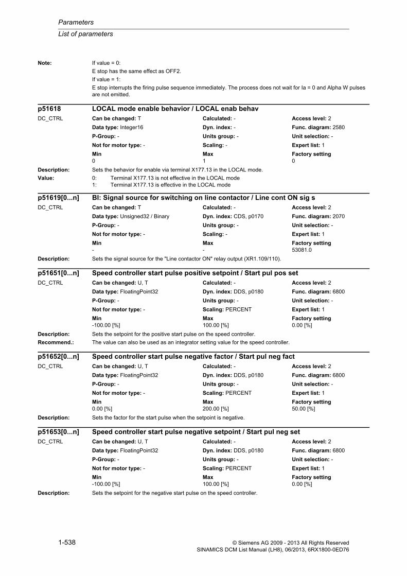
Parameters
List of parameters
1-538 © Siemens AG 2009 - 2013 All Rights ReservedSINAMICS DCM List Manual (LH8), 06/2013, 6RX1800-0ED76
Note: If value = 0:
E stop has the same effect as OFF2.
If value = 1:
E stop interrupts the firing pulse sequence immediately. The process does not wait for Ia = 0 and Alpha W pulses are not emitted.
Description: Sets the behavior for enable via terminal X177.13 in the LOCAL mode.
Value: 0: Terminal X177.13 is not effective in the LOCAL mode1: Terminal X177.13 is effective in the LOCAL mode
Description: Sets the signal source for the "Line contactor ON" relay output (XR1.109/110).
Description: Sets the setpoint for the positive start pulse on the speed controller.
Recommend.: The value can also be used as an integrator setting value for the speed controller.
Description: Sets the factor for the start pulse when the setpoint is negative.
Description: Sets the setpoint for the negative start pulse on the speed controller.
p51618 LOCAL mode enable behavior / LOCAL enab behavDC_CTRL Can be changed: T Calculated: - Access level: 2
Data type: Integer16 Dyn. index: - Func. diagram: 2580
P-Group: - Units group: - Unit selection: -
Not for motor type: - Scaling: - Expert list: 1
Min Max Factory setting 0 1 0
p51619[0...n] BI: Signal source for switching on line contactor / Line cont ON sig sDC_CTRL Can be changed: T Calculated: - Access level: 2
Data type: Unsigned32 / Binary Dyn. index: CDS, p0170 Func. diagram: 2070
P-Group: - Units group: - Unit selection: -
Not for motor type: - Scaling: - Expert list: 1
Min Max Factory setting - - 53081.0
p51651[0...n] Speed controller start pulse positive setpoint / Start pul pos setDC_CTRL Can be changed: U, T Calculated: - Access level: 2
Data type: FloatingPoint32 Dyn. index: DDS, p0180 Func. diagram: 6800
P-Group: - Units group: - Unit selection: -
Not for motor type: - Scaling: PERCENT Expert list: 1
Min Max Factory setting -100.00 [%] 100.00 [%] 0.00 [%]
p51652[0...n] Speed controller start pulse negative factor / Start pul neg factDC_CTRL Can be changed: U, T Calculated: - Access level: 2
Data type: FloatingPoint32 Dyn. index: DDS, p0180 Func. diagram: 6800
P-Group: - Units group: - Unit selection: -
Not for motor type: - Scaling: PERCENT Expert list: 1
Min Max Factory setting 0.00 [%] 200.00 [%] 50.00 [%]
p51653[0...n] Speed controller start pulse negative setpoint / Start pul neg setDC_CTRL Can be changed: U, T Calculated: - Access level: 2
Data type: FloatingPoint32 Dyn. index: DDS, p0180 Func. diagram: 6800
P-Group: - Units group: - Unit selection: -
Not for motor type: - Scaling: PERCENT Expert list: 1
Min Max Factory setting -100.00 [%] 100.00 [%] 0.00 [%]

List of parameters
Parameters
1-539© Siemens AG 2009 - 2013 All Rights ReservedSINAMICS DCM List Manual (LH8), 06/2013, 6RX1800-0ED76
Description: Sets the signal source for the setpoint of the positive start pulse on the speed controller.
Description: Sets the signal source for the setpoint of the negative start pulse on the speed controller.
Description: Sets the signal source for changing over the setpoint between positive and negative start pulses on the speed con-troller.
Description: Sets the signal source for travel command 1 on the 4-step master switch.
Description: Sets the signal source for travel command 2 on the 4-step master switch.
p51655 CI: Speed controller start pulse positive signal source / Start p pos sig sDC_CTRL Can be changed: T Calculated: - Access level: 2
Data type: Unsigned32 / FloatingPoint32 Dyn. index: - Func. diagram: 6800
P-Group: - Units group: - Unit selection: -
Not for motor type: - Scaling: PERCENT Expert list: 1
Min Max Factory setting - - 52451[0]
p51656 CI: Speed controller start pulse negative signal source / Start p neg sig sDC_CTRL Can be changed: T Calculated: - Access level: 2
Data type: Unsigned32 / FloatingPoint32 Dyn. index: - Func. diagram: 6800
P-Group: - Units group: - Unit selection: -
Not for motor type: - Scaling: PERCENT Expert list: 1
Min Max Factory setting - - 52452[0]
p51657[0...n] BI: Speed controller start pulse pos/neg changeover signal source / Start p ch sig sDC_CTRL Can be changed: T Calculated: - Access level: 2
Data type: Unsigned32 / Binary Dyn. index: CDS, p0170 Func. diagram: 6800
P-Group: - Units group: - Unit selection: -
Not for motor type: - Scaling: - Expert list: 1
Min Max Factory setting - - 0
p51660 BI: Signal source for master switch travel command 1 / Trav comm 1 sig sDC_CTRL Can be changed: T Calculated: - Access level: 2
Data type: Unsigned32 / Binary Dyn. index: - Func. diagram: 3105
P-Group: - Units group: - Unit selection: -
Not for motor type: - Scaling: - Expert list: 1
Min Max Factory setting - - 0
p51661 BI: Signal source for master switch travel command 2 / Trav comm 2 sig sDC_CTRL Can be changed: T Calculated: - Access level: 2
Data type: Unsigned32 / Binary Dyn. index: - Func. diagram: 3105
P-Group: - Units group: - Unit selection: -
Not for motor type: - Scaling: - Expert list: 1
Min Max Factory setting - - 0

Parameters
List of parameters
1-540 © Siemens AG 2009 - 2013 All Rights ReservedSINAMICS DCM List Manual (LH8), 06/2013, 6RX1800-0ED76
Description: Sets the signal source for changing over to setpoint step S2 on the 4-step master switch.
Description: Sets the signal source for changing over to setpoint step S3 on the 4-step master switch.
Description: Sets the signal source for changing over to setpoint step S4 on the 4-step master switch.
Description: Sets the setpoint for setpoint step S1 on the 4-step master switch.
Description: Sets the setpoint for setpoint step S2 on the 4-step master switch.
p51662 BI: Signal source for master switch setpoint step S2 / Set step S2 sig sDC_CTRL Can be changed: T Calculated: - Access level: 2
Data type: Unsigned32 / Binary Dyn. index: - Func. diagram: 3105
P-Group: - Units group: - Unit selection: -
Not for motor type: - Scaling: - Expert list: 1
Min Max Factory setting - - 0
p51663 BI: Signal source for master switch setpoint step S3 / Set step S3 sig sDC_CTRL Can be changed: T Calculated: - Access level: 2
Data type: Unsigned32 / Binary Dyn. index: - Func. diagram: 3105
P-Group: - Units group: - Unit selection: -
Not for motor type: - Scaling: - Expert list: 1
Min Max Factory setting - - 0
p51664 BI: Signal source for master switch setpoint step S4 / Set step S4 sig sDC_CTRL Can be changed: T Calculated: - Access level: 2
Data type: Unsigned32 / Binary Dyn. index: - Func. diagram: 3105
P-Group: - Units group: - Unit selection: -
Not for motor type: - Scaling: - Expert list: 1
Min Max Factory setting - - 0
p51665 Master switch setpoint step S1 value / Set step S1 valueDC_CTRL Can be changed: U, T Calculated: - Access level: 2
Data type: FloatingPoint32 Dyn. index: - Func. diagram: 3105
P-Group: - Units group: - Unit selection: -
Not for motor type: - Scaling: PERCENT Expert list: 1
Min Max Factory setting 0.00 [%] 110.00 [%] 10.00 [%]
p51666 Master switch setpoint step S2 value / Set step S2 valueDC_CTRL Can be changed: U, T Calculated: - Access level: 2
Data type: FloatingPoint32 Dyn. index: - Func. diagram: 3105
P-Group: - Units group: - Unit selection: -
Not for motor type: - Scaling: PERCENT Expert list: 1
Min Max Factory setting 0.00 [%] 110.00 [%] 25.00 [%]

List of parameters
Parameters
1-541© Siemens AG 2009 - 2013 All Rights ReservedSINAMICS DCM List Manual (LH8), 06/2013, 6RX1800-0ED76
Description: Sets the setpoint for setpoint step S3 on the 4-step master switch.
Description: Sets the setpoint for setpoint step S4 on the 4-step master switch.
Description: Sets the signal source for the connectors to be recorded by the recorder function.
Dependency: Refer to: p51701, p51702, p51703, p51704, p51705, p51706
Note: [0] = Signal source for the first connector to be recorded
[1] = Signal source for the second connector to be recorded
Description: Sets the signal source for the binectors to be recorded by the recorder function.
Dependency: Refer to: p51700, p51702, p51703, p51704, p51705, p51706
Note: [0] = Signal source for the first binector to be recorded
[1] = Signal source for the second binector to be recorded
Description: Setting to select the channels to be recorded.
p51667 Master switch setpoint step S3 value / Set step S3 valueDC_CTRL Can be changed: U, T Calculated: - Access level: 2
Data type: FloatingPoint32 Dyn. index: - Func. diagram: 3105
P-Group: - Units group: - Unit selection: -
Not for motor type: - Scaling: PERCENT Expert list: 1
Min Max Factory setting 0.00 [%] 110.00 [%] 40.00 [%]
p51668 Master switch setpoint step S4 value / Set step S4 valueDC_CTRL Can be changed: U, T Calculated: - Access level: 2
Data type: FloatingPoint32 Dyn. index: - Func. diagram: 3105
P-Group: - Units group: - Unit selection: -
Not for motor type: - Scaling: PERCENT Expert list: 1
Min Max Factory setting 0.00 [%] 110.00 [%] 100.00 [%]
p51700[0...1] CI: Signal source for connector recorder function / Rec fct con sig sDC_CTRL Can be changed: U, T Calculated: - Access level: 2
Data type: Unsigned32 / FloatingPoint32 Dyn. index: - Func. diagram: 8050
P-Group: - Units group: - Unit selection: -
Not for motor type: - Scaling: PERCENT Expert list: 1
Min Max Factory setting - - 0
p51701[0...1] BI: Signal source for binector recorder function / Rec fct bin sig sDC_CTRL Can be changed: U, T Calculated: - Access level: 2
Data type: Unsigned32 / Binary Dyn. index: - Func. diagram: 8050
P-Group: - Units group: - Unit selection: -
Not for motor type: - Scaling: - Expert list: 1
Min Max Factory setting - - 0
p51702 Recorder function channel selection / Rec fct selDC_CTRL Can be changed: U, T Calculated: - Access level: 2
Data type: Unsigned32 Dyn. index: - Func. diagram: 8050
P-Group: - Units group: - Unit selection: -
Not for motor type: - Scaling: - Expert list: 1
Min Max Factory setting - - 1111 bin

Parameters
List of parameters
1-542 © Siemens AG 2009 - 2013 All Rights ReservedSINAMICS DCM List Manual (LH8), 06/2013, 6RX1800-0ED76
Dependency: Refer to: p51700, p51701, p51703, p51704, p51705, p51706
Description: Sets the recording interval,
during which the signals selected with the channel selection parameters (p51702.0 to 3) are scanned and saved internally.
Dependency: Refer to: p51700, p51701, p51702, p51704, p51705, p51706
Description: Sets the save interval,
during which the signals recorded internally are saved to the following recording file:
\USER\SINAMICS\DATA\LOG\Track.csv
Dependency: Refer to: p51700, p51701, p51702, p51703, p51705, p51706
Notice: The value is set in minutes.
Description: Setting to start and stop the recorder function.
Value = 1:
Recording is started and stopped after reaching of the number of entries set in p51706. p51705 is set to 0.
Value = 2:
Recording is started: After reaching of the number of entries set in p51706, the file is overwritten from the begin-ning.
Recording runs until it is stopped by setting of p51705 = 0.
Value: 0: Stop1: Start2: Start with overwrite
Dependency: Refer to: p51700, p51701, p51702, p51703, p51704, p51706
Notice: Starting the recorder function overwrites any existing recording file.
Bit field: Bit Signal name 1 signal 0 signal FP00 Channel 0 Active Not active -01 Channel 1 Active Not active -02 Channel 2 Active Not active -03 Channel 3 Active Not active -
p51703 Recorder function recording interval / Rec fct t_recDC_CTRL Can be changed: U, T Calculated: - Access level: 2
Data type: Unsigned32 Dyn. index: - Func. diagram: 8050
P-Group: - Units group: - Unit selection: -
Not for motor type: - Scaling: - Expert list: 1
Min Max Factory setting 1 [s] 1000 [s] 1 [s]
p51704 Recorder function save interval / Rec fct t_saveDC_CTRL Can be changed: U, T Calculated: - Access level: 2
Data type: Unsigned32 Dyn. index: - Func. diagram: 8050
P-Group: - Units group: - Unit selection: -
Not for motor type: - Scaling: - Expert list: 1
Min Max Factory setting 1 60 1
p51705 Start/stop recorder function / Rec fct StartStopDC_CTRL Can be changed: U, T Calculated: - Access level: 2
Data type: Integer16 Dyn. index: - Func. diagram: 8050
P-Group: - Units group: - Unit selection: -
Not for motor type: - Scaling: - Expert list: 1
Min Max Factory setting 0 2 0
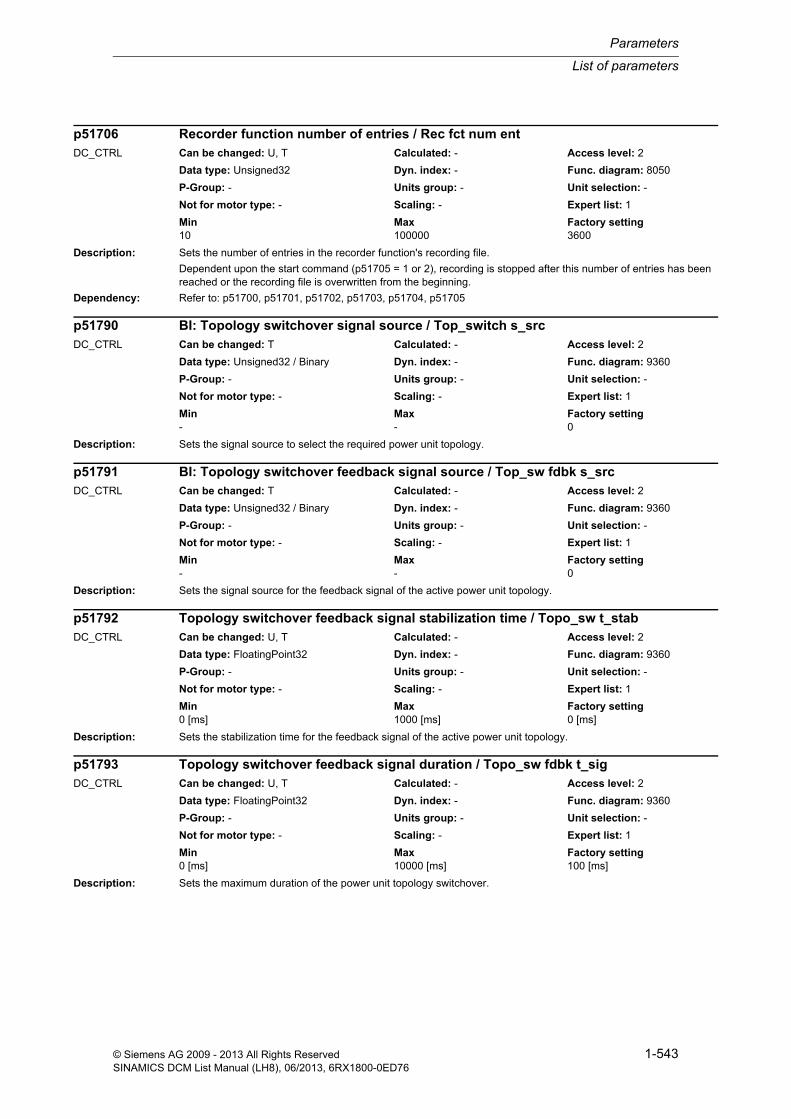
List of parameters
Parameters
1-543© Siemens AG 2009 - 2013 All Rights ReservedSINAMICS DCM List Manual (LH8), 06/2013, 6RX1800-0ED76
Description: Sets the number of entries in the recorder function's recording file.
Dependent upon the start command (p51705 = 1 or 2), recording is stopped after this number of entries has been reached or the recording file is overwritten from the beginning.
Dependency: Refer to: p51700, p51701, p51702, p51703, p51704, p51705
Description: Sets the signal source to select the required power unit topology.
Description: Sets the signal source for the feedback signal of the active power unit topology.
Description: Sets the stabilization time for the feedback signal of the active power unit topology.
Description: Sets the maximum duration of the power unit topology switchover.
p51706 Recorder function number of entries / Rec fct num entDC_CTRL Can be changed: U, T Calculated: - Access level: 2
Data type: Unsigned32 Dyn. index: - Func. diagram: 8050
P-Group: - Units group: - Unit selection: -
Not for motor type: - Scaling: - Expert list: 1
Min Max Factory setting 10 100000 3600
p51790 BI: Topology switchover signal source / Top_switch s_srcDC_CTRL Can be changed: T Calculated: - Access level: 2
Data type: Unsigned32 / Binary Dyn. index: - Func. diagram: 9360
P-Group: - Units group: - Unit selection: -
Not for motor type: - Scaling: - Expert list: 1
Min Max Factory setting - - 0
p51791 BI: Topology switchover feedback signal source / Top_sw fdbk s_srcDC_CTRL Can be changed: T Calculated: - Access level: 2
Data type: Unsigned32 / Binary Dyn. index: - Func. diagram: 9360
P-Group: - Units group: - Unit selection: -
Not for motor type: - Scaling: - Expert list: 1
Min Max Factory setting - - 0
p51792 Topology switchover feedback signal stabilization time / Topo_sw t_stabDC_CTRL Can be changed: U, T Calculated: - Access level: 2
Data type: FloatingPoint32 Dyn. index: - Func. diagram: 9360
P-Group: - Units group: - Unit selection: -
Not for motor type: - Scaling: - Expert list: 1
Min Max Factory setting 0 [ms] 1000 [ms] 0 [ms]
p51793 Topology switchover feedback signal duration / Topo_sw fdbk t_sigDC_CTRL Can be changed: U, T Calculated: - Access level: 2
Data type: FloatingPoint32 Dyn. index: - Func. diagram: 9360
P-Group: - Units group: - Unit selection: -
Not for motor type: - Scaling: - Expert list: 1
Min Max Factory setting 0 [ms] 10000 [ms] 100 [ms]

Parameters
List of parameters
1-544 © Siemens AG 2009 - 2013 All Rights ReservedSINAMICS DCM List Manual (LH8), 06/2013, 6RX1800-0ED76
Description: Sets the mode of operation of the armature converter for power unit topology 2.
Value: 0: Standard mode of operation1: Sole power unit 1-phase3: Sole power unit 3-phase21: 12-pulse parallel, firing angle from the master22: 12-pulse parallel, firing angle master/slave31: 6-pulse serial, firing angle from the master32: 6-pulse serial with sequential phase control41: 12-pulse serial, firing angle from the master42: 12-pulse serial with sequential phase control
Dependency: Refer to: p51795
Note: Comments, the same as for p51799
Description: Sets the position of the power unit in converter topology 2.
Value: 0: Parallel interface not active1: Power unit independent/CUD right11: 6-pulse parallel master12: 6-pulse parallel slave13: 6-pulse parallel slave/replacement master21: 12-pulse parallel master22: 12-pulse parallel slave23: 12-pulse parallel, slave parallel to master24: 12-pulse parallel, slave parallel to slave31: 6-pulse serial master32: 6-pulse serial slave33: 6-pulse serial parallel to master34: 6-pulse serial parallel to slave35: 6-pulse serial master, slave is a diode bridge41: 12-pulse serial master42: 12-pulse serial slave43: 12-pulse serial parallel to master44: 12-pulse serial parallel to slave45: 12-pulse serial master, slave is a diode bridge
Dependency: Refer to: p51799
Note: Comments, the same as for p51800
p51794 Topology switchover armature converter mode of operation 2 / Topo_sw mode 2DC_CTRL Can be changed: T Calculated: - Access level: 3
Data type: Integer16 Dyn. index: - Func. diagram: 9360
P-Group: - Units group: - Unit selection: -
Not for motor type: - Scaling: - Expert list: 1
Min Max Factory setting 0 42 0
p51795 Topology switchover power unit topology position 2 / Topo_sw pos 2DC_CTRL Can be changed: T Calculated: - Access level: 2
Data type: Integer16 Dyn. index: - Func. diagram: 9360
P-Group: - Units group: - Unit selection: -
Not for motor type: - Scaling: - Expert list: 1
Min Max Factory setting 0 45 0

List of parameters
Parameters
1-545© Siemens AG 2009 - 2013 All Rights ReservedSINAMICS DCM List Manual (LH8), 06/2013, 6RX1800-0ED76
Description: Sets the switch-on threshold and hysteresis for the phase sequence control.
The values are referred to the rated device current r50072[1].
Index: [0] = Switch-on threshold[1] = Hysteresis
Dependency: Refer to: p51799
Note: The switch-off threshold is calculated as follows:
Switch-off threshold = switch-on threshold - hysteresis
Description: Sets the line voltage at the diode bridge for a 6-pulse/12-pulse series circuit of a SINAMICS DCM with an uncon-trolled rectifier (diode bridge).
Note: The value set here is a percentage of the line voltage at the SINAMICS DCM.
Description: Sets the mode of operation of the armature converter
Value: 0: Standard mode of operation1: Sole power unit 1-phase3: Sole power unit 3-phase21: 12-pulse parallel, firing angle from the master22: 12-pulse parallel, firing angle master/slave31: 6-pulse serial, firing angle from the master32: 6-pulse serial with sequential phase control41: 12-pulse serial, firing angle from the master42: 12-pulse serial with sequential phase control
Dependency: Refer to: p51797, p51800
Note: If value = 0:
Standard for the corresponding topology (acc. to p51800).
If value = 1:
Sole power unit in 1-phase operation (line connection at inputs 1U and 1V).
If value = 3:
Sole power unit in 3-phase operation (= standard).
If value = 21:
12-pulse parallel connection with central firing angle generation in the master (= standard).
p51797[0...1] Sequential phase control switch-on threshold/hysteresis / Seq ph ctr on/hysDC_CTRL Can be changed: T Calculated: - Access level: 3
Data type: FloatingPoint32 Dyn. index: - Func. diagram: 6860
P-Group: - Units group: - Unit selection: -
Not for motor type: - Scaling: PERCENT Expert list: 1
Min Max Factory setting 5 [%] 100 [%] [0] 35 [%]
[1] 30 [%]
p51798 Armature converter voltage diode bridge / Ia_convert U diodeDC_CTRL Can be changed: T Calculated: - Access level: 3
Data type: FloatingPoint32 Dyn. index: - Func. diagram: 6902
P-Group: - Units group: - Unit selection: -
Not for motor type: - Scaling: PERCENT Expert list: 1
Min Max Factory setting 50.00 [%] 100.00 [%] 85.00 [%]
p51799 Armature converter mode of operation / Ia_conv mode_opDC_CTRL Can be changed: T Calculated: - Access level: 3
Data type: Integer16 Dyn. index: - Func. diagram: 6855
P-Group: - Units group: - Unit selection: -
Not for motor type: - Scaling: - Expert list: 1
Min Max Factory setting 0 42 0
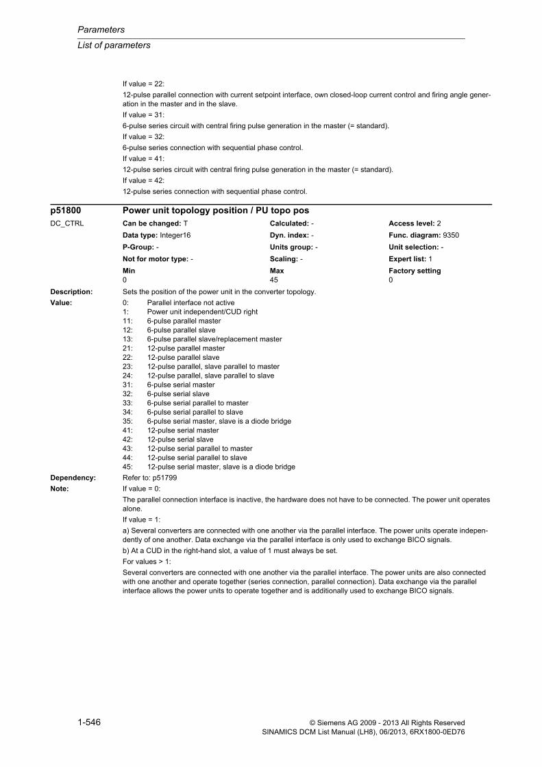
Parameters
List of parameters
1-546 © Siemens AG 2009 - 2013 All Rights ReservedSINAMICS DCM List Manual (LH8), 06/2013, 6RX1800-0ED76
If value = 22:
12-pulse parallel connection with current setpoint interface, own closed-loop current control and firing angle gener-ation in the master and in the slave.
If value = 31:
6-pulse series circuit with central firing pulse generation in the master (= standard).
If value = 32:
6-pulse series connection with sequential phase control.
If value = 41:
12-pulse series circuit with central firing pulse generation in the master (= standard).
If value = 42:
12-pulse series connection with sequential phase control.
Description: Sets the position of the power unit in the converter topology.
Value: 0: Parallel interface not active1: Power unit independent/CUD right11: 6-pulse parallel master12: 6-pulse parallel slave13: 6-pulse parallel slave/replacement master21: 12-pulse parallel master22: 12-pulse parallel slave23: 12-pulse parallel, slave parallel to master24: 12-pulse parallel, slave parallel to slave31: 6-pulse serial master32: 6-pulse serial slave33: 6-pulse serial parallel to master34: 6-pulse serial parallel to slave35: 6-pulse serial master, slave is a diode bridge41: 12-pulse serial master42: 12-pulse serial slave43: 12-pulse serial parallel to master44: 12-pulse serial parallel to slave45: 12-pulse serial master, slave is a diode bridge
Dependency: Refer to: p51799
Note: If value = 0:
The parallel connection interface is inactive, the hardware does not have to be connected. The power unit operates alone.
If value = 1:
a) Several converters are connected with one another via the parallel interface. The power units operate indepen-dently of one another. Data exchange via the parallel interface is only used to exchange BICO signals.
b) At a CUD in the right-hand slot, a value of 1 must always be set.
For values > 1:
Several converters are connected with one another via the parallel interface. The power units are also connected with one another and operate together (series connection, parallel connection). Data exchange via the parallel interface allows the power units to operate together and is additionally used to exchange BICO signals.
p51800 Power unit topology position / PU topo posDC_CTRL Can be changed: T Calculated: - Access level: 2
Data type: Integer16 Dyn. index: - Func. diagram: 9350
P-Group: - Units group: - Unit selection: -
Not for motor type: - Scaling: - Expert list: 1
Min Max Factory setting 0 45 0

List of parameters
Parameters
1-547© Siemens AG 2009 - 2013 All Rights ReservedSINAMICS DCM List Manual (LH8), 06/2013, 6RX1800-0ED76
Description: Sets the number of words to be transmitted on the parallel interface.
Value: 0: 0 words4: 4 words8: 8 words12: 12 words16: 16 words
Description: Sets the number of converters whose power units operate together in the selected converter topology (p51800).
Note: For a 6-pulse parallel connection (p51800 = 11, 12 or 13) and activated redundant operation (p51803 = 1), then the power units may fail (e.g. go into a fault condition). In this operating mode, using this parameter, the minimum num-ber of power units must be set which must be ready for operation.
In all other cases, the number of power units that operate together must be precisely set.
Description: Setting to activate/de-activate redundancy mode for the parallel interface.
Value: 0: Deactivated1: Activated armature2: Activated armature + field
Note: When a SINAMICS DCM is operated together with a SIMOREG DC-MASTER Converter Commutation Protector (CCP), then the redundant mode must be deactivated.
Description: Sets the signal sources for transmit data when operating the device as a slave on the parallel interface.
Index: [0] = Word 1[1] = Word 2[2] = Word 3[3] = Word 4[4] = Word 5
p51801 Parallel interface number of transmit data / Par IF num tr dataDC_CTRL Can be changed: T Calculated: - Access level: 2
Data type: Integer16 Dyn. index: - Func. diagram: 9355
P-Group: - Units group: - Unit selection: -
Not for motor type: - Scaling: - Expert list: 1
Min Max Factory setting 0 16 4
p51802 Parallel interface number of power units / Par_IF PU qtyDC_CTRL Can be changed: T Calculated: - Access level: 2
Data type: Unsigned8 Dyn. index: - Func. diagram: 9350
P-Group: - Units group: - Unit selection: -
Not for motor type: - Scaling: - Expert list: 1
Min Max Factory setting 1 16 1
p51803 Parallel interface activation of redundancy mode / Par IF redund modDC_CTRL Can be changed: T Calculated: - Access level: 2
Data type: Integer16 Dyn. index: - Func. diagram: 9350
P-Group: - Units group: - Unit selection: -
Not for motor type: - Scaling: - Expert list: 1
Min Max Factory setting 0 2 0
p51804[0...15] CI: Parallel interface slave transmit data / PI slave tr dataDC_CTRL Can be changed: U, T Calculated: - Access level: 2
Data type: Unsigned32 / Integer16 Dyn. index: - Func. diagram: 9355
P-Group: - Units group: - Unit selection: -
Not for motor type: - Scaling: 4000H Expert list: 1
Min Max Factory setting - - 0

Parameters
List of parameters
1-548 © Siemens AG 2009 - 2013 All Rights ReservedSINAMICS DCM List Manual (LH8), 06/2013, 6RX1800-0ED76
[5] = Word 6[6] = Word 7[7] = Word 8[8] = Word 9[9] = Word 10[10] = Word 11[11] = Word 12[12] = Word 13[13] = Word 14[14] = Word 15[15] = Word 16
Description: Setting to activate/de-activate the bus terminator on the parallel interface.
Value: 0: Bus terminator OFF1: Bus terminator ON
Dependency: Refer to: p51806
Description: Sets the bus address for the parallel connection of devices.
Dependency: Refer to: p51805
Description: Sets the permissible telegram failure time for the parallel interface.
This setting means that every device connected to the parallel switching interface can monitor whether it is con-nected to the parallel switching interface.
If a telegram is not received from any other device connected to the parallel switching interface for longer than the set time, then BICO output r53310.0 is set to 1, and also fault F60014 is initiated in the factory setting.
Value = 0.0:
Telegram monitoring is de-activated.
Value = 0.001 ... 65.000:
Telegram monitoring is activated.
Dependency: Refer to: p50099, r53310
p51805 Parallel interface bus terminator / Par IF bus termDC_CTRL Can be changed: U, T Calculated: - Access level: 2
Data type: Integer16 Dyn. index: - Func. diagram: 9350
P-Group: - Units group: - Unit selection: -
Not for motor type: - Scaling: - Expert list: 1
Min Max Factory setting 0 1 0
p51806 Parallel interface bus address / Par IF bus addrDC_CTRL Can be changed: T Calculated: - Access level: 2
Data type: Unsigned16 Dyn. index: - Func. diagram: 9350
P-Group: - Units group: - Unit selection: -
Not for motor type: - Scaling: - Expert list: 1
Min Max Factory setting 1 16 1
p51807 Parallel interface telegram monitoring failure time / Telegr mon t_failDC_CTRL Can be changed: U, T Calculated: - Access level: 2
Data type: FloatingPoint32 Dyn. index: - Func. diagram: 9350
P-Group: - Units group: - Unit selection: -
Not for motor type: - Scaling: - Expert list: 1
Min Max Factory setting 0.000 [s] 65.000 [s] 0.100 [s]

List of parameters
Parameters
1-549© Siemens AG 2009 - 2013 All Rights ReservedSINAMICS DCM List Manual (LH8), 06/2013, 6RX1800-0ED76
Note: Telegram monitoring is active in the following cases:
- From the first error-free telegram received after the electronic power supply has been switched on The telegram can be received from any device.
- From the first telegram received error-free after the telegram monitoring has responded (as a result of the failure time expiring).
Description: Sets the signal source for triggering fault F60014 "Telegram monitoring timeout".
The fault is triggered on a 1 signal.
Dependency: Refer to: r53310
Description: Displays the diagnostic information for the parallel interface.
Index: [0] = Telegrams transmitted without errors[1] = Telegrams received without errors[2] = Transmission error[3] = Receive error[4] = Timeouts
Dependency: Refer to: p51807
Note: The counters are reset to 0 at POWER ON.
The counters restart at 0 after reaching a value of 65535.
Description: Displays the activities on the individual stations on the parallel interface.
p51808 BI: Parallel interface signal source for F60014 / P IF F60014 sig sDC_CTRL Can be changed: T Calculated: - Access level: 2
Data type: Unsigned32 / Binary Dyn. index: - Func. diagram: 9350
P-Group: - Units group: - Unit selection: -
Not for motor type: - Scaling: - Expert list: 1
Min Max Factory setting - - 53310.0
r51809[0...4] Parallel interface diagnostic information / Par IF diag infoDC_CTRL Can be changed: - Calculated: - Access level: 1
Data type: Unsigned16 Dyn. index: - Func. diagram: 9350
P-Group: - Units group: - Unit selection: -
Not for motor type: - Scaling: - Expert list: 1
Min Max Factory setting - - -
r51810 Parallel interface activity display / Par IF act dispDC_CTRL Can be changed: - Calculated: - Access level: 1
Data type: Unsigned16 Dyn. index: - Func. diagram: 9350
P-Group: - Units group: - Unit selection: -
Not for motor type: - Scaling: - Expert list: 1
Min Max Factory setting - - -
Bit field: Bit Signal name 1 signal 0 signal FP00 Station 1 transmitting data Yes No -01 Station 2 transmitting data Yes No -02 Station 3 transmitting data Yes No -03 Station 4 transmitting data Yes No -04 Station 5 transmitting data Yes No -05 Station 6 transmitting data Yes No -06 Station 7 transmitting data Yes No -07 Station 8 transmitting data Yes No -08 Station 9 transmitting data Yes No -09 Station 10 transmitting data Yes No -10 Station 11 transmitting data Yes No -11 Station 12 transmitting data Yes No -

Parameters
List of parameters
1-550 © Siemens AG 2009 - 2013 All Rights ReservedSINAMICS DCM List Manual (LH8), 06/2013, 6RX1800-0ED76
Description: Displays the CAN diagnostic information for the parallel interface.
Description: Displays the data selected for transmission.
Index: [0] = Word 1[1] = Word 2[2] = Word 3[3] = Word 4[4] = Word 5[5] = Word 6[6] = Word 7[7] = Word 8[8] = Word 9[9] = Word 10[10] = Word 11[11] = Word 12[12] = Word 13[13] = Word 14[14] = Word 15[15] = Word 16
12 Station 13 transmitting data Yes No -13 Station 14 transmitting data Yes No -14 Station 15 transmitting data Yes No -15 Station 16 transmitting data Yes No -
r51811 Parallel interface CAN diagnostic information / PI CAN diag infoDC_CTRL Can be changed: - Calculated: - Access level: 1
Data type: Unsigned16 Dyn. index: - Func. diagram: 9350
P-Group: - Units group: - Unit selection: -
Not for motor type: - Scaling: - Expert list: 1
Min Max Factory setting - - -
Bit field: Bit Signal name 1 signal 0 signal FP00 Abort acknowledge flag 935001 Write denied flag 935002 Wake-up flag 935003 Received msg lost flag 935004 Bus-off condition flag 935005 Error passive mode flag 935006 Warning level flag 935007 Form error flag 935008 Bit error flag 935009 Stuck at dominant bit 935010 CRC error 935011 Stuff bit error 935012 ACK error 935013 Bus-off status 935014 Error passive state 935015 Warning status 9350
r51813[0...15] Parallel interface transmit data display / PI trans data dispDC_CTRL Can be changed: - Calculated: - Access level: 1
Data type: Unsigned16 Dyn. index: - Func. diagram: 9355
P-Group: - Units group: - Unit selection: -
Not for motor type: - Scaling: - Expert list: 1
Min Max Factory setting - - -

List of parameters
Parameters
1-551© Siemens AG 2009 - 2013 All Rights ReservedSINAMICS DCM List Manual (LH8), 06/2013, 6RX1800-0ED76
Description: Sets the signal sources for transmit data when operating the device as a master on the parallel interface.
Index: [0] = Word 1[1] = Word 2[2] = Word 3[3] = Word 4[4] = Word 5[5] = Word 6[6] = Word 7[7] = Word 8[8] = Word 9[9] = Word 10[10] = Word 11[11] = Word 12[12] = Word 13[13] = Word 14[14] = Word 15[15] = Word 16
Note: This parameter is used to define the transmit data and its position in the transmit telegram.
[0]: Word 1 in the telegram
...
[4]: Word 5 in the telegram
[5]: Word 1 in the telegram
...
[9]: Word 5 in the telegram
...
Description: Sets the number of CUDs, which communicate with one another via the parallel switching interface.
This setting is intended so that every device connected to the parallel switching interface can monitor whether all devices are active and/or available.
Each of the devices connected to the parallel switching interface continually monitors whether all of the devices reg-ularly send telegrams.
"Device connected to the parallel switching interface" is every CUD, at which p51800 > 0 .
"Regularly sending telegrams" means that the time between two send telegrams from the same device must be less than 100 ms.
Note: - If the number set here is less than the actual number of devices connected to the parallel switching interface, then failure of some of the devices is ignored.
- A setting of 1 means that the monitoring is inactive.
p51814[0...15] CI: Parallel interface master transmit data / PI master tr dataDC_CTRL Can be changed: U, T Calculated: - Access level: 2
Data type: Unsigned32 / Integer16 Dyn. index: - Func. diagram: 9355
P-Group: - Units group: - Unit selection: -
Not for motor type: - Scaling: 4000H Expert list: 1
Min Max Factory setting - - 0
p51815 Parallel interface number of devices / Par_IF device qtyDC_CTRL Can be changed: T Calculated: - Access level: 2
Data type: Unsigned8 Dyn. index: - Func. diagram: 9350
P-Group: - Units group: - Unit selection: -
Not for motor type: - Scaling: - Expert list: 1
Min Max Factory setting 1 16 1

Parameters
List of parameters
1-552 © Siemens AG 2009 - 2013 All Rights ReservedSINAMICS DCM List Manual (LH8), 06/2013, 6RX1800-0ED76
Description: Sets the ratio between output and input voltage on the external voltage transformer for line and armature voltage.
Index: [0] = Line voltage[1] = Armature voltage
Note: The parameter is only effective on the Control Module.
Example:
Output voltage = 100 V
Input voltage = 2000 V
--> p51819 = 100 V / 2000 V = 0.050
Description: Sets the rated supply voltage (rms value) for which the power unit is suitable (electric strength of the thyristors).
Note: The parameter is only effective on the Control Module.
The set supply voltage is displayed in r50071.
Parameter p50078[0] (armature rated input voltage) is limited to this value.
Description: Sets the connections used to measure the line voltage and the armature voltage on the A7117 module.
Value: 0: No selection6: XU6 / XV6 / XW6 or XC6 / XD650: XU5 / XV5 / XW5 or XC5 / XD5125: XU4 / XV4 / XW4 or XC4 / XD4250: XU3 / XV3 / XW3 or XC3 / XD3575: XU2 / XV2 / XW2 or XC2 / XD21000: XU1 / XV1 / XW1 or XC1 / XD1
Index: [0] = Line voltage[1] = Armature voltage
Note: The parameter is only effective on the Control Module.
The parameter value indicates the rated rms value of the maximum measurable line voltage.
p51819[0...1] External voltage transformer transformation ratio / V transf ext ratioDC_CTRL Can be changed: T Calculated: - Access level: 2
Data type: FloatingPoint32 Dyn. index: - Func. diagram: 6950, 6965
P-Group: - Units group: - Unit selection: -
Not for motor type: - Scaling: - Expert list: 1
Min Max Factory setting 0.000100 1.000000 1.000000
p51820 Armature rated supply voltage / Arm V_ratedDC_CTRL Can be changed: T Calculated: - Access level: 2
Data type: FloatingPoint32 Dyn. index: - Func. diagram: 6965
P-Group: - Units group: - Unit selection: -
Not for motor type: - Scaling: - Expert list: 1
Min Max Factory setting 50 [Vrms] 5000 [Vrms] 1000 [Vrms]
p51821[0...1] Measurement cable connection / Meas cab connDC_CTRL Can be changed: T Calculated: - Access level: 2
Data type: Integer16 Dyn. index: - Func. diagram: 6965
P-Group: - Units group: - Unit selection: -
Not for motor type: - Scaling: - Expert list: 1
Min Max Factory setting 0 1000 1000

List of parameters
Parameters
1-553© Siemens AG 2009 - 2013 All Rights ReservedSINAMICS DCM List Manual (LH8), 06/2013, 6RX1800-0ED76
Description: Sets the rated direct current for the armature.
The output direct current supported by the power unit in continuous operation should be set in this parameter.
Note: The parameter is only effective on the Control Module.
Description: Sets the load voltage resulting from the following calculation formula:
V_load = R_load * tr * Id
V_load: The load voltage to be set in this parameter
R_load: The load resistance (default 10 ohm)
r: Transformation ratio of the current transformer (I2 / I1)
Id: Output direct current according to parameter p51822
Note: The parameter is only effective on the Control Module.
Description: Sets the configuration for the current transformer for current actual value sensing.
Value: 1: Current transformer in phase U and V2: Current transformer in phase U and W3: Current transformer in phase V and W4: External current transformer connected in V circuit5: Bipolar current actual value signal (external shunt)
Note: The parameter is only effective on the Control Module.
Description: Sets the power unit type.
Value: 2: 2-quadrant power unit4: 4-quadrant power unit
Note: The parameter is only effective on the Control Module.
p51822 Armature rated direct current / Arm I_ratedDC_CTRL Can be changed: T Calculated: - Access level: 2
Data type: FloatingPoint32 Dyn. index: - Func. diagram: 6965
P-Group: - Units group: - Unit selection: -
Not for motor type: - Scaling: - Expert list: 1
Min Max Factory setting 0.1 [A] 20000.0 [A] 0.1 [A]
p51823 Load voltage at armature rated current / V_load Ia_ratedDC_CTRL Can be changed: T Calculated: - Access level: 2
Data type: FloatingPoint32 Dyn. index: - Func. diagram: 6850, 6965
P-Group: - Units group: - Unit selection: -
Not for motor type: - Scaling: - Expert list: 1
Min Max Factory setting 0.2000 [V] 1.2000 [V] 1.0000 [V]
p51824 Current transformer configuration / I_transf configDC_CTRL Can be changed: T Calculated: - Access level: 2
Data type: Integer16 Dyn. index: - Func. diagram: 6850, 6965
P-Group: - Units group: - Unit selection: -
Not for motor type: - Scaling: - Expert list: 1
Min Max Factory setting 1 5 2
p51825 Power unit type / PU typDC_CTRL Can be changed: T Calculated: - Access level: 2
Data type: Integer16 Dyn. index: - Func. diagram: 6965
P-Group: - Units group: - Unit selection: -
Not for motor type: - Scaling: - Expert list: 1
Min Max Factory setting 2 4 2

Parameters
List of parameters
1-554 © Siemens AG 2009 - 2013 All Rights ReservedSINAMICS DCM List Manual (LH8), 06/2013, 6RX1800-0ED76
Description: Sets the times for firing pulse chopping on the armature current converter.
Index: [0] = Length of first pulse[1] = Length additional pulses[2] = Break length
Note: The parameter is only effective on the Control Module.
Block pulses are generated (i.e. firing pulses without pulse chopping) with the following setting:
- p51826[0] = 105 µs
- p51826[1] = 105 µs
- p51826[1] = 0 µs
Description: Sets the threshold for temperature monitoring on the Control Module.
Index: [0] = Temperature sensor 1 / XT5 / A7109[1] = Temperature sensor 2 / XT6 / A7109[2] = Temperature sensor 3 / XT7 / A7116
Dependency: Refer to: p51830
Note: The parameter is only effective on the Control Module.
Description: Sets the sensor type for the temperature sensors on the Control Module.
Value: 0: No temperature sensor present1: NTC with 6.8 kOhm2: NTC with 10 kOhm
Index: [0] = Temperature sensor 1 / XT5 / A7109[1] = Temperature sensor 2 / XT6 / A7109[2] = Temperature sensor 3 / XT7 / A7116
Dependency: Refer to: p51829
Note: The NTC temperature sensor should be connected at module A7109 or A7116 at terminal XT5, XT6 or XT7.
The parameter is only effective on the Control Module.
p51826[0...2] Armature current converter firing pulse chopping times / Pulse chop tDC_CTRL Can be changed: T Calculated: - Access level: 2
Data type: FloatingPoint32 Dyn. index: - Func. diagram: 6860, 6965
P-Group: - Units group: - Unit selection: -
Not for motor type: - Scaling: - Expert list: 1
Min Max Factory setting 0 [µs] 105 [µs] [0] 50 [µs]
[1] 35 [µs]
[2] 70 [µs]
p51829[0...2] Heat sink temperature threshold / Htsk temp threshDC_CTRL Can be changed: U, T Calculated: - Access level: 2
Data type: FloatingPoint32 Dyn. index: - Func. diagram: 8048
P-Group: - Units group: - Unit selection: -
Not for motor type: - Scaling: - Expert list: 1
Min Max Factory setting 0.0 [°C] 200.0 [°C] 90.0 [°C]
p51830[0...2] Heat sink temperature sensor type / Htsk temp typeDC_CTRL Can be changed: T Calculated: - Access level: 2
Data type: Integer16 Dyn. index: - Func. diagram: 8048
P-Group: - Units group: - Unit selection: -
Not for motor type: - Scaling: - Expert list: 1
Min Max Factory setting 0 2 0

List of parameters
Parameters
1-555© Siemens AG 2009 - 2013 All Rights ReservedSINAMICS DCM List Manual (LH8), 06/2013, 6RX1800-0ED76
Description: Setting to activate/de-activate fuse monitoring on the Control Module.
Value: 0: Deactivated1: Activated
Index: [0] = Connector X23B[1] = Connector X23C[2] = Connector X23D[3] = Connector X23E[4] = Connector X23F
Note: The parameter is only effective on the Control Module.
Connector X23B is available on the power interface and on the expansion module (A7112 module). Monitoring at connectors X23C to X23F is only possible using the expansion module.
Only groups of up to 6 inputs can be activated and de-activated at the same time.
If an expansion module is connected to slot X23A, slot X23B cannot be used on the power interface.
Description: Sets the configuration for fan monitoring on the Control Module.
Value: 0: OFF1: ON and Low active2: ON and High active
Dependency: Refer to: r53140
Note: Fan monitoring is wired via input terminal 122/123.
The parameter can only be changed for the Control Module.
Description: Sets the mode to trigger the external fault F60203 via input terminal 124/125 on the Control Module.
Value: 0: Switched off1: Switched on and Low level triggers fault2: Switched on and High level triggers fault
Dependency: Refer to: r53140
Note: The parameter can only be changed for the Control Module.
If value = 1:
The input signal is available via binector output r53140.4 for further interconnection.
If value = 2:
The input signal is available via binector output r53140.3 for further interconnection.
p51831[0...4] Fuse monitoring activation / Fuse mon actDC_CTRL Can be changed: T Calculated: - Access level: 2
Data type: Integer16 Dyn. index: - Func. diagram: 6957, 6965
P-Group: - Units group: - Unit selection: -
Not for motor type: - Scaling: - Expert list: 1
Min Max Factory setting 0 1 0
p51832 Fan monitoring configuration / Fan mon configDC_CTRL Can be changed: T Calculated: - Access level: 2
Data type: Integer16 Dyn. index: - Func. diagram: 8049
P-Group: - Units group: - Unit selection: -
Not for motor type: - Scaling: - Expert list: 1
Min Max Factory setting 0 2 1
p51833 External fault mode / Ext F modeDC_CTRL Can be changed: T Calculated: - Access level: 2
Data type: Integer16 Dyn. index: - Func. diagram: 6965, 8049
P-Group: - Units group: - Unit selection: -
Not for motor type: - Scaling: - Expert list: 1
Min Max Factory setting 0 2 1

Parameters
List of parameters
1-556 © Siemens AG 2009 - 2013 All Rights ReservedSINAMICS DCM List Manual (LH8), 06/2013, 6RX1800-0ED76
Description: Sets the signal source for the "Fan On" relay output (terminal 120/121) on the power interface.
Note: The parameter can only be changed for the Control Module.
Description: Sets the delay times for device fan monitoring on the Control Module.
Index: [0] = ON delay monitoring[1] = ON delay fault[2] = ON delay alarm
Note: The parameter can only be changed for the Control Module.
Description: Sets the rated direct current of an external field device (if there is one).
Dependency: Refer to: p50082
Note: This parameter is only effective if p50082 >= 21.
Description: Setting for activating/de-activating the monitoring for the external field.
Value: 0: Deactivated1: Activated
Dependency: Refer to: p50082
p51834 BI: Signal source for device fan relay output / Fan relay sig sDC_CTRL Can be changed: T Calculated: - Access level: 2
Data type: Unsigned32 / Binary Dyn. index: - Func. diagram: 6965, 8049
P-Group: - Units group: - Unit selection: -
Not for motor type: - Scaling: - Expert list: 1
Min Max Factory setting - - 0
p51835[0...2] Delay times for device fan monitoring / Fan mon t_delDC_CTRL Can be changed: T Calculated: - Access level: 2
Data type: FloatingPoint32 Dyn. index: - Func. diagram: 8049
P-Group: - Units group: - Unit selection: -
Not for motor type: - Scaling: - Expert list: 1
Min Max Factory setting 0.0 [s] 60.0 [s] [0] 15.0 [s]
[1] 5.0 [s]
[2] 2.0 [s]
p51838 Field device external rated direct current / I_rated extDC_CTRL Can be changed: T Calculated: - Access level: 2
Data type: FloatingPoint32 Dyn. index: - Func. diagram: 6960, 6910
P-Group: - Units group: - Unit selection: -
Not for motor type: - Scaling: - Expert list: 1
Min Max Factory setting 0.00 [A] 600.00 [A] 0.00 [A]
p51839 External field monitoring / Ext field monitDC_CTRL Can be changed: U, T Calculated: - Access level: 2
Data type: Integer16 Dyn. index: - Func. diagram: 8044
P-Group: - Units group: - Unit selection: -
Not for motor type: - Scaling: - Expert list: 1
Min Max Factory setting 0 1 0
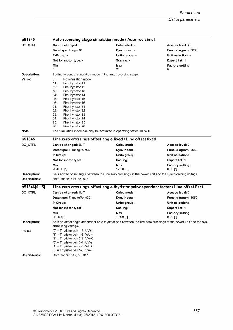
List of parameters
Parameters
1-557© Siemens AG 2009 - 2013 All Rights ReservedSINAMICS DCM List Manual (LH8), 06/2013, 6RX1800-0ED76
Description: Setting to control simulation mode in the auto-reversing stage.
Value: 0: No simulation mode11: Fire thyristor 1112: Fire thyristor 1213: Fire thyristor 1314: Fire thyristor 1415: Fire thyristor 1516: Fire thyristor 1621: Fire thyristor 2122: Fire thyristor 2223: Fire thyristor 2324: Fire thyristor 2425: Fire thyristor 2526: Fire thyristor 26
Note: The simulation mode can only be activated in operating states >= o7.0.
Description: Sets a fixed offset angle between the line zero crossings at the power unit and the synchronizing voltage.
Dependency: Refer to: p51846, p51847
Description: Sets an offset angle dependent on a thyristor pair between the line zero crossings at the power unit and the syn-chronizing voltage.
Index: [0] = Thyristor pair 1-6 (UV+)[1] = Thyristor pair 1-2 (WU-)[2] = Thyristor pair 2-3 (VW+)[3] = Thyristor pair 3-4 (UV-)[4] = Thyristor pair 4-5 (WU+)[5] = Thyristor pair 5-6 (VW-)
Dependency: Refer to: p51845, p51847
p51840 Auto-reversing stage simulation mode / Auto-rev simulDC_CTRL Can be changed: T Calculated: - Access level: 2
Data type: Integer16 Dyn. index: - Func. diagram: 6865
P-Group: - Units group: - Unit selection: -
Not for motor type: - Scaling: - Expert list: 1
Min Max Factory setting 0 26 0
p51845 Line zero crossings offset angle fixed / Line offset fixedDC_CTRL Can be changed: U, T Calculated: - Access level: 3
Data type: FloatingPoint32 Dyn. index: - Func. diagram: 6950
P-Group: - Units group: - Unit selection: -
Not for motor type: - Scaling: - Expert list: 1
Min Max Factory setting -120.00 [°] 120.00 [°] 0.00 [°]
p51846[0...5] Line zero crossings offset angle thyristor pair-dependent factor / Line offset FactDC_CTRL Can be changed: U, T Calculated: - Access level: 3
Data type: FloatingPoint32 Dyn. index: - Func. diagram: 6950
P-Group: - Units group: - Unit selection: -
Not for motor type: - Scaling: - Expert list: 1
Min Max Factory setting -10.00 [°] 10.00 [°] 0.00 [°]
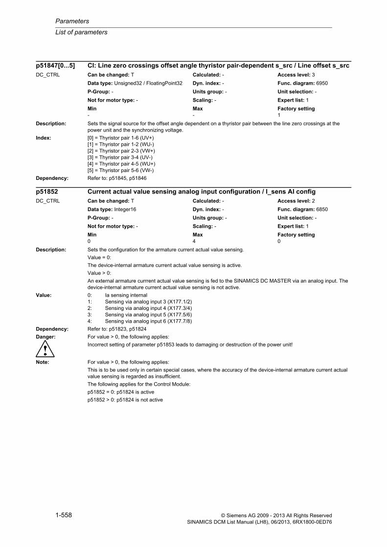
Parameters
List of parameters
1-558 © Siemens AG 2009 - 2013 All Rights ReservedSINAMICS DCM List Manual (LH8), 06/2013, 6RX1800-0ED76
Description: Sets the signal source for the offset angle dependent on a thyristor pair between the line zero crossings at the power unit and the synchronizing voltage.
Index: [0] = Thyristor pair 1-6 (UV+)[1] = Thyristor pair 1-2 (WU-)[2] = Thyristor pair 2-3 (VW+)[3] = Thyristor pair 3-4 (UV-)[4] = Thyristor pair 4-5 (WU+)[5] = Thyristor pair 5-6 (VW-)
Dependency: Refer to: p51845, p51846
Description: Sets the configuration for the armature current actual value sensing.
Value = 0:
The device-internal armature current actual value sensing is active.
Value > 0:
An external armature currrent actual value sensing is fed to the SINAMICS DC MASTER via an analog input. The device-internal armature current actual value sensing is not active.
Value: 0: Ia sensing internal1: Sensing via analog input 3 (X177.1/2)2: Sensing via analog input 4 (X177.3/4)3: Sensing via analog input 5 (X177.5/6)4: Sensing via analog input 6 (X177.7/8)
Dependency: Refer to: p51823, p51824
Danger: For value > 0, the following applies:
Incorrect setting of parameter p51853 leads to damaging or destruction of the power unit!
Note: For value > 0, the following applies:
This is to be used only in certain special cases, where the accuracy of the device-internal armature current actual value sensing is regarded as insufficient.
The following applies for the Control Module:
p51852 = 0: p51824 is active
p51852 > 0: p51824 is not active
p51847[0...5] CI: Line zero crossings offset angle thyristor pair-dependent s_src / Line offset s_srcDC_CTRL Can be changed: T Calculated: - Access level: 3
Data type: Unsigned32 / FloatingPoint32 Dyn. index: - Func. diagram: 6950
P-Group: - Units group: - Unit selection: -
Not for motor type: - Scaling: - Expert list: 1
Min Max Factory setting - - 1
p51852 Current actual value sensing analog input configuration / I_sens AI configDC_CTRL Can be changed: T Calculated: - Access level: 2
Data type: Integer16 Dyn. index: - Func. diagram: 6850
P-Group: - Units group: - Unit selection: -
Not for motor type: - Scaling: - Expert list: 1
Min Max Factory setting 0 4 0
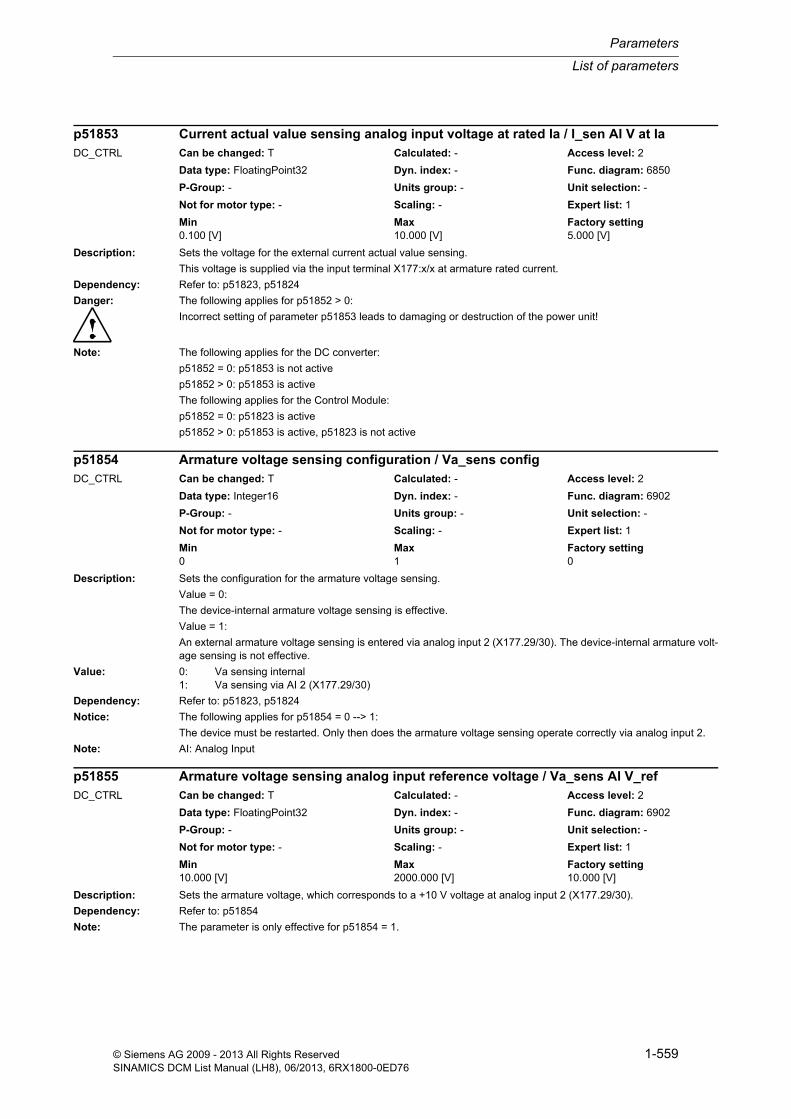
List of parameters
Parameters
1-559© Siemens AG 2009 - 2013 All Rights ReservedSINAMICS DCM List Manual (LH8), 06/2013, 6RX1800-0ED76
Description: Sets the voltage for the external current actual value sensing.
This voltage is supplied via the input terminal X177:x/x at armature rated current.
Dependency: Refer to: p51823, p51824
Danger: The following applies for p51852 > 0:
Incorrect setting of parameter p51853 leads to damaging or destruction of the power unit!
Note: The following applies for the DC converter:
p51852 = 0: p51853 is not active
p51852 > 0: p51853 is active
The following applies for the Control Module:
p51852 = 0: p51823 is active
p51852 > 0: p51853 is active, p51823 is not active
Description: Sets the configuration for the armature voltage sensing.
Value = 0:
The device-internal armature voltage sensing is effective.
Value = 1:
An external armature voltage sensing is entered via analog input 2 (X177.29/30). The device-internal armature volt-age sensing is not effective.
Value: 0: Va sensing internal1: Va sensing via AI 2 (X177.29/30)
Dependency: Refer to: p51823, p51824
Notice: The following applies for p51854 = 0 --> 1:
The device must be restarted. Only then does the armature voltage sensing operate correctly via analog input 2.
Note: AI: Analog Input
Description: Sets the armature voltage, which corresponds to a +10 V voltage at analog input 2 (X177.29/30).
Dependency: Refer to: p51854
Note: The parameter is only effective for p51854 = 1.
p51853 Current actual value sensing analog input voltage at rated Ia / I_sen AI V at IaDC_CTRL Can be changed: T Calculated: - Access level: 2
Data type: FloatingPoint32 Dyn. index: - Func. diagram: 6850
P-Group: - Units group: - Unit selection: -
Not for motor type: - Scaling: - Expert list: 1
Min Max Factory setting 0.100 [V] 10.000 [V] 5.000 [V]
p51854 Armature voltage sensing configuration / Va_sens configDC_CTRL Can be changed: T Calculated: - Access level: 2
Data type: Integer16 Dyn. index: - Func. diagram: 6902
P-Group: - Units group: - Unit selection: -
Not for motor type: - Scaling: - Expert list: 1
Min Max Factory setting 0 1 0
p51855 Armature voltage sensing analog input reference voltage / Va_sens AI V_refDC_CTRL Can be changed: T Calculated: - Access level: 2
Data type: FloatingPoint32 Dyn. index: - Func. diagram: 6902
P-Group: - Units group: - Unit selection: -
Not for motor type: - Scaling: - Expert list: 1
Min Max Factory setting 10.000 [V] 2000.000 [V] 10.000 [V]

Parameters
List of parameters
1-560 © Siemens AG 2009 - 2013 All Rights ReservedSINAMICS DCM List Manual (LH8), 06/2013, 6RX1800-0ED76
Description: Connector output with constant fixed value 0 %.
Description: Connector output with constant fixed value 100 %.
Description: Connector output with constant fixed value 200 %.
Description: Connector output with constant fixed value -100 %.
Description: Connector output with constant fixed value -200 %.
r52000 CO: Fixed value 0 % / Fix val 0%DC_CTRL Can be changed: - Calculated: - Access level: 2
Data type: FloatingPoint32 Dyn. index: - Func. diagram: 3100
P-Group: - Units group: - Unit selection: -
Not for motor type: - Scaling: - Expert list: 1
Min Max Factory setting - [%] - [%] - [%]
r52001 CO: Fixed value 100 % / Fix val 100%DC_CTRL Can be changed: - Calculated: - Access level: 2
Data type: FloatingPoint32 Dyn. index: - Func. diagram: 3100
P-Group: - Units group: - Unit selection: -
Not for motor type: - Scaling: - Expert list: 1
Min Max Factory setting - [%] - [%] - [%]
r52002 CO: Fixed value 200 % / Fix val 200%DC_CTRL Can be changed: - Calculated: - Access level: 2
Data type: FloatingPoint32 Dyn. index: - Func. diagram: 3100
P-Group: - Units group: - Unit selection: -
Not for motor type: - Scaling: - Expert list: 1
Min Max Factory setting - [%] - [%] - [%]
r52003 CO: Fixed value -100 % / Fix val -100%DC_CTRL Can be changed: - Calculated: - Access level: 2
Data type: FloatingPoint32 Dyn. index: - Func. diagram: 3100
P-Group: - Units group: - Unit selection: -
Not for motor type: - Scaling: - Expert list: 1
Min Max Factory setting - [%] - [%] - [%]
r52004 CO: Fixed value -200 % / Fix val -200%DC_CTRL Can be changed: - Calculated: - Access level: 2
Data type: FloatingPoint32 Dyn. index: - Func. diagram: 3100
P-Group: - Units group: - Unit selection: -
Not for motor type: - Scaling: - Expert list: 1
Min Max Factory setting - [%] - [%] - [%]
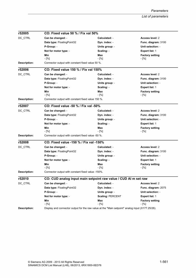
List of parameters
Parameters
1-561© Siemens AG 2009 - 2013 All Rights ReservedSINAMICS DCM List Manual (LH8), 06/2013, 6RX1800-0ED76
Description: Connector output with constant fixed value 50 %.
Description: Connector output with constant fixed value 150 %.
Description: Connector output with constant fixed value -50 %.
Description: Connector output with constant fixed value -150%.
Description: Display and connector output for the raw value at the "Main setpoint" analog input (X177.25/26).
r52005 CO: Fixed value 50 % / Fix val 50%DC_CTRL Can be changed: - Calculated: - Access level: 2
Data type: FloatingPoint32 Dyn. index: - Func. diagram: 3100
P-Group: - Units group: - Unit selection: -
Not for motor type: - Scaling: - Expert list: 1
Min Max Factory setting - [%] - [%] - [%]
r52006 CO: Fixed value 150 % / Fix val 150%DC_CTRL Can be changed: - Calculated: - Access level: 2
Data type: FloatingPoint32 Dyn. index: - Func. diagram: 3100
P-Group: - Units group: - Unit selection: -
Not for motor type: - Scaling: - Expert list: 1
Min Max Factory setting - [%] - [%] - [%]
r52007 CO: Fixed value -50 % / Fix val -50%DC_CTRL Can be changed: - Calculated: - Access level: 2
Data type: FloatingPoint32 Dyn. index: - Func. diagram: 3100
P-Group: - Units group: - Unit selection: -
Not for motor type: - Scaling: - Expert list: 1
Min Max Factory setting - [%] - [%] - [%]
r52008 CO: Fixed value -150 % / Fix val -150%DC_CTRL Can be changed: - Calculated: - Access level: 2
Data type: FloatingPoint32 Dyn. index: - Func. diagram: 3100
P-Group: - Units group: - Unit selection: -
Not for motor type: - Scaling: - Expert list: 1
Min Max Factory setting - [%] - [%] - [%]
r52010 CO: CUD analog input main setpoint raw value / CUD AI m set rawDC_CTRL Can be changed: - Calculated: - Access level: 2
Data type: FloatingPoint32 Dyn. index: - Func. diagram: 2075
P-Group: - Units group: - Unit selection: -
Not for motor type: - Scaling: PERCENT Expert list: 1
Min Max Factory setting - [%] - [%] - [%]
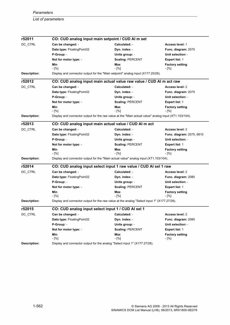
Parameters
List of parameters
1-562 © Siemens AG 2009 - 2013 All Rights ReservedSINAMICS DCM List Manual (LH8), 06/2013, 6RX1800-0ED76
Description: Display and connector output for the "Main setpoint" analog input (X177.25/26).
Description: Display and connector output for the raw value at the "Main actual value" analog input (XT1.103/104).
Description: Display and connector output for the "Main actual value" analog input (XT1.103/104).
Description: Display and connector output for the raw value at the analog "Select input 1" (X177.27/28).
Description: Display and connector output for the analog "Select input 1" (X177.27/28).
r52011 CO: CUD analog input main setpoint / CUD AI m setDC_CTRL Can be changed: - Calculated: - Access level: 1
Data type: FloatingPoint32 Dyn. index: - Func. diagram: 2075
P-Group: - Units group: - Unit selection: -
Not for motor type: - Scaling: PERCENT Expert list: 1
Min Max Factory setting - [%] - [%] - [%]
r52012 CO: CUD analog input main actual value raw value / CUD AI m act rawDC_CTRL Can be changed: - Calculated: - Access level: 2
Data type: FloatingPoint32 Dyn. index: - Func. diagram: 2075
P-Group: - Units group: - Unit selection: -
Not for motor type: - Scaling: PERCENT Expert list: 1
Min Max Factory setting - [%] - [%] - [%]
r52013 CO: CUD analog input main actual value / CUD AI m actDC_CTRL Can be changed: - Calculated: - Access level: 2
Data type: FloatingPoint32 Dyn. index: - Func. diagram: 2075, 6810
P-Group: - Units group: - Unit selection: -
Not for motor type: - Scaling: PERCENT Expert list: 1
Min Max Factory setting - [%] - [%] - [%]
r52014 CO: CUD analog input select input 1 raw value / CUD AI sel 1 rawDC_CTRL Can be changed: - Calculated: - Access level: 2
Data type: FloatingPoint32 Dyn. index: - Func. diagram: 2080
P-Group: - Units group: - Unit selection: -
Not for motor type: - Scaling: PERCENT Expert list: 1
Min Max Factory setting - [%] - [%] - [%]
r52015 CO: CUD analog input select input 1 / CUD AI sel 1DC_CTRL Can be changed: - Calculated: - Access level: 2
Data type: FloatingPoint32 Dyn. index: - Func. diagram: 2080
P-Group: - Units group: - Unit selection: -
Not for motor type: - Scaling: PERCENT Expert list: 1
Min Max Factory setting - [%] - [%] - [%]

List of parameters
Parameters
1-563© Siemens AG 2009 - 2013 All Rights ReservedSINAMICS DCM List Manual (LH8), 06/2013, 6RX1800-0ED76
Description: Display and connector output for the raw value at the analog "Select input 2" (X177.29/30).
Description: Display and connector output for the analog "Select input 2" (X177.29/30).
Description: Display and connector output for the raw value at analog input 3 (X177.1/2) on the CUD.
Dependency: Refer to: r52019
Note: AI: Analog Input
Description: Display and connector output for the conversion result at analog input 3 (X177.1/2) on the CUD.
Description: Display and connector output for the raw value at analog input 4 (X177.3/4) on the CUD.
Dependency: Refer to: r52021
r52016 CO: CUD analog input select input 2 raw value / CUD AI sel 2 rawDC_CTRL Can be changed: - Calculated: - Access level: 2
Data type: FloatingPoint32 Dyn. index: - Func. diagram: 2080
P-Group: - Units group: - Unit selection: -
Not for motor type: - Scaling: PERCENT Expert list: 1
Min Max Factory setting - [%] - [%] - [%]
r52017 CO: CUD analog input select input 2 / CUD AI sel 2DC_CTRL Can be changed: - Calculated: - Access level: 2
Data type: FloatingPoint32 Dyn. index: - Func. diagram: 2080
P-Group: - Units group: - Unit selection: -
Not for motor type: - Scaling: PERCENT Expert list: 1
Min Max Factory setting - [%] - [%] - [%]
r52018 CO: CUD analog input 3 raw value / CUD AI 3 rawDC_CTRL Can be changed: - Calculated: - Access level: 2
Data type: FloatingPoint32 Dyn. index: - Func. diagram: 2085
P-Group: - Units group: - Unit selection: -
Not for motor type: - Scaling: PERCENT Expert list: 1
Min Max Factory setting - [%] - [%] - [%]
r52019 CO: CUD analog input 3 result / CUD AI 3 resDC_CTRL Can be changed: - Calculated: - Access level: 2
Data type: FloatingPoint32 Dyn. index: - Func. diagram: 2085
P-Group: - Units group: - Unit selection: -
Not for motor type: - Scaling: PERCENT Expert list: 1
Min Max Factory setting - [%] - [%] - [%]
r52020 CO: CUD analog input 4 raw value / CUD AI 4 rawDC_CTRL Can be changed: - Calculated: - Access level: 2
Data type: FloatingPoint32 Dyn. index: - Func. diagram: 2085
P-Group: - Units group: - Unit selection: -
Not for motor type: - Scaling: PERCENT Expert list: 1
Min Max Factory setting - [%] - [%] - [%]

Parameters
List of parameters
1-564 © Siemens AG 2009 - 2013 All Rights ReservedSINAMICS DCM List Manual (LH8), 06/2013, 6RX1800-0ED76
Description: Display and connector output for the conversion result at analog input 4 (X177.3/4) on the CUD.
Description: Display and connector output for the raw value at analog input 5 (X177.5/6) on the CUD.
Dependency: Refer to: r52023
Description: Display and connector output for the conversion result at analog input 5 (X177.5/6) on the CUD.
Description: Display and connector output for the raw value at analog input 6 (X177.7/8) on the CUD.
Dependency: Refer to: r52025
Description: Display and connector output for the conversion result at analog input 6 (X177.7/8) on the CUD.
r52021 CO: CUD analog input 4 result / CUD AI 4 resDC_CTRL Can be changed: - Calculated: - Access level: 2
Data type: FloatingPoint32 Dyn. index: - Func. diagram: 2085
P-Group: - Units group: - Unit selection: -
Not for motor type: - Scaling: PERCENT Expert list: 1
Min Max Factory setting - [%] - [%] - [%]
r52022 CO: CUD analog input 5 raw value / CUD AI 5 rawDC_CTRL Can be changed: - Calculated: - Access level: 2
Data type: FloatingPoint32 Dyn. index: - Func. diagram: 2090
P-Group: - Units group: - Unit selection: -
Not for motor type: - Scaling: PERCENT Expert list: 1
Min Max Factory setting - [%] - [%] - [%]
r52023 CO: CUD analog input 5 result / CUD AI 5 resDC_CTRL Can be changed: - Calculated: - Access level: 2
Data type: FloatingPoint32 Dyn. index: - Func. diagram: 2090
P-Group: - Units group: - Unit selection: -
Not for motor type: - Scaling: PERCENT Expert list: 1
Min Max Factory setting - [%] - [%] - [%]
r52024 CO: CUD analog input 6 raw value / CUD AI 6 rawDC_CTRL Can be changed: - Calculated: - Access level: 2
Data type: FloatingPoint32 Dyn. index: - Func. diagram: 2090
P-Group: - Units group: - Unit selection: -
Not for motor type: - Scaling: PERCENT Expert list: 1
Min Max Factory setting - [%] - [%] - [%]
r52025 CO: CUD analog input 6 result / CUD AI 6 resDC_CTRL Can be changed: - Calculated: - Access level: 2
Data type: FloatingPoint32 Dyn. index: - Func. diagram: 2090
P-Group: - Units group: - Unit selection: -
Not for motor type: - Scaling: PERCENT Expert list: 1
Min Max Factory setting - [%] - [%] - [%]

List of parameters
Parameters
1-565© Siemens AG 2009 - 2013 All Rights ReservedSINAMICS DCM List Manual (LH8), 06/2013, 6RX1800-0ED76
Description: Display and connector output for analog output 0 (X177.49/50) on the CUD.
Dependency: Refer to: p50750
Note: AO: Analog Output
Description: Display and connector output for analog output 1 (X177.51/52) on the CUD.
Dependency: Refer to: p50755
Note: AO: Analog Output
Description: Display and connector output for the braking distance required as increments of the pulse encoder defined in p0400.
The pulse encoder to be used must be selected using p50331.
The required braking distance is calculated assuming that the speed setpoint at the ramp-function generator input has been set to 0 and the speed actual value is approaching 0, taking the set ramp-down time and roundings into consideration.
Note: For p0400[p50331] = 0, a braking distance of 0 is displayed.
The braking distance calculation is only correct if the ramp-down time and the roundings do not change during brak-ing (p50302, r00899.5, p50637, p50638).
Description: Display and connector output for the braking distance required as increments of the pulse encoder defined in p0400.
The pulse encoder to be used must be selected using p50331.
The required braking distance is calculated assuming that the speed setpoint at the ramp-function generator input has been set to 0 and the speed actual value is approaching 0, taking the set ramp-down time and roundings into consideration.
r52026 CO: CUD analog output 0 value after smoothing / CUD AO 0 v aft smDC_CTRL Can be changed: - Calculated: - Access level: 2
Data type: FloatingPoint32 Dyn. index: - Func. diagram: 2095
P-Group: - Units group: - Unit selection: -
Not for motor type: - Scaling: PERCENT Expert list: 1
Min Max Factory setting - [%] - [%] - [%]
r52027 CO: CUD analog output 1 value after smoothing / CUD AO 1 v aft smDC_CTRL Can be changed: - Calculated: - Access level: 2
Data type: FloatingPoint32 Dyn. index: - Func. diagram: 2095
P-Group: - Units group: - Unit selection: -
Not for motor type: - Scaling: PERCENT Expert list: 1
Min Max Factory setting - [%] - [%] - [%]
r52047 CO: Ramp-function generator braking distance (Unsigned32) / RFG brake dist U32DC_CTRL Can be changed: - Calculated: - Access level: 3
Data type: Unsigned32 Dyn. index: - Func. diagram: 3152
P-Group: - Units group: - Unit selection: -
Not for motor type: - Scaling: - Expert list: 1
Min Max Factory setting - - -
r52048 CO: Ramp-function generator braking distance (FloatingPoint32) / RFG br dist floatDC_CTRL Can be changed: - Calculated: - Access level: 3
Data type: FloatingPoint32 Dyn. index: - Func. diagram: 3152
P-Group: - Units group: - Unit selection: -
Not for motor type: - Scaling: - Expert list: 1
Min Max Factory setting - - -

Parameters
List of parameters
1-566 © Siemens AG 2009 - 2013 All Rights ReservedSINAMICS DCM List Manual (LH8), 06/2013, 6RX1800-0ED76
Note: For p0400[p50331] = 0, a braking distance of 0 is displayed.
The braking distance calculation is only correct if the ramp-down time and the roundings do not change during brak-ing (p50302, r00899.5, p50637, p50638).
Description: Displays the integrated temperature sensors.
Note: The display is independent of the temperature sensor status and only indicates the desired state.
Description: Display and connector output for the device's temperature outputs.
Index: [0] = Temperature 1[1] = Temperature 2[2] = Temperature 3[3] = Gating module temperature[4] = CUD Control Unit temperature
Note: Temperature sensors which are not in use return a high negative value (approx. -200 °C).
Description: Display and connector output for the motor temperature.
Scaling:
0 % corresponds to 0 °C
100 % corresponds to 100 °C
Dependency: The parameter is only valid for the following temperature sensors with a continuous characteristic:
- KTY84 (p50490 = 1)
- PT100 (p50490 = 6)
- NTC thermistor K227 (p50490 = 7)
- PT1000 (p50490 = 8)
Refer to: p50490
Note: If p50490 = 0, 2 to 5, a value of 0 is displayed.
r52049 Temperature sensor available / Temp_sens availDC_CTRL Can be changed: - Calculated: - Access level: 1
Data type: Unsigned16 Dyn. index: - Func. diagram: 6960
P-Group: - Units group: - Unit selection: -
Not for motor type: - Scaling: - Expert list: 1
Min Max Factory setting - - -
Bit field: Bit Signal name 1 signal 0 signal FP00 Temperature sensor XT5 Available Not present 696001 Temperature sensor XT6 Available Not present 696002 Temperature sensor XT7 Available Not present 696003 Gating module temperature sensor Available Not present 6960
r52050[0...4] CO: Temperature sensor display / Temp sensor dispDC_CTRL Can be changed: - Calculated: - Access level: 1
Data type: FloatingPoint32 Dyn. index: - Func. diagram: 8047, 8048
P-Group: - Units group: - Unit selection: -
Not for motor type: - Scaling: PERCENT Expert list: 1
Min Max Factory setting - [%] - [%] - [%]
r52051 CO: Motor temperature output / Mot temp outpDC_CTRL Can be changed: - Calculated: - Access level: 1
Data type: FloatingPoint32 Dyn. index: - Func. diagram: 8030
P-Group: - Units group: - Unit selection: -
Not for motor type: - Scaling: PERCENT Expert list: 1
Min Max Factory setting - [%] - [%] - [%]
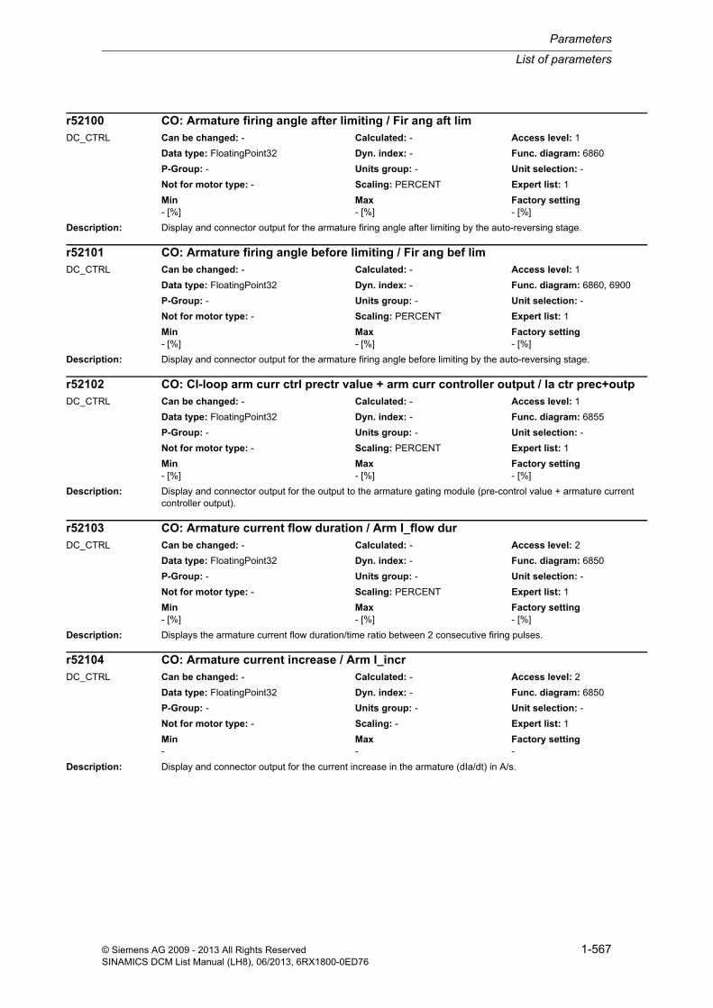
List of parameters
Parameters
1-567© Siemens AG 2009 - 2013 All Rights ReservedSINAMICS DCM List Manual (LH8), 06/2013, 6RX1800-0ED76
Description: Display and connector output for the armature firing angle after limiting by the auto-reversing stage.
Description: Display and connector output for the armature firing angle before limiting by the auto-reversing stage.
Description: Display and connector output for the output to the armature gating module (pre-control value + armature current controller output).
Description: Displays the armature current flow duration/time ratio between 2 consecutive firing pulses.
Description: Display and connector output for the current increase in the armature (dIa/dt) in A/s.
r52100 CO: Armature firing angle after limiting / Fir ang aft limDC_CTRL Can be changed: - Calculated: - Access level: 1
Data type: FloatingPoint32 Dyn. index: - Func. diagram: 6860
P-Group: - Units group: - Unit selection: -
Not for motor type: - Scaling: PERCENT Expert list: 1
Min Max Factory setting - [%] - [%] - [%]
r52101 CO: Armature firing angle before limiting / Fir ang bef limDC_CTRL Can be changed: - Calculated: - Access level: 1
Data type: FloatingPoint32 Dyn. index: - Func. diagram: 6860, 6900
P-Group: - Units group: - Unit selection: -
Not for motor type: - Scaling: PERCENT Expert list: 1
Min Max Factory setting - [%] - [%] - [%]
r52102 CO: Cl-loop arm curr ctrl prectr value + arm curr controller output / Ia ctr prec+outpDC_CTRL Can be changed: - Calculated: - Access level: 1
Data type: FloatingPoint32 Dyn. index: - Func. diagram: 6855
P-Group: - Units group: - Unit selection: -
Not for motor type: - Scaling: PERCENT Expert list: 1
Min Max Factory setting - [%] - [%] - [%]
r52103 CO: Armature current flow duration / Arm I_flow durDC_CTRL Can be changed: - Calculated: - Access level: 2
Data type: FloatingPoint32 Dyn. index: - Func. diagram: 6850
P-Group: - Units group: - Unit selection: -
Not for motor type: - Scaling: PERCENT Expert list: 1
Min Max Factory setting - [%] - [%] - [%]
r52104 CO: Armature current increase / Arm I_incrDC_CTRL Can be changed: - Calculated: - Access level: 2
Data type: FloatingPoint32 Dyn. index: - Func. diagram: 6850
P-Group: - Units group: - Unit selection: -
Not for motor type: - Scaling: - Expert list: 1
Min Max Factory setting - - -

Parameters
List of parameters
1-568 © Siemens AG 2009 - 2013 All Rights ReservedSINAMICS DCM List Manual (LH8), 06/2013, 6RX1800-0ED76
Description: Displays the requested torque direction.
Note: Value = 0: No torque direction requested
Value = 1: Torque direction 1 requested
Value = 2: Torque direction 2 requested
Description: Display and connector output of the signed armature current actual value.
The value is averaged over 6 firing cycles and referenced to the rated motor current.
Description: Display and connector output for the rms values of the phase currents.
The values are averaged over six firing cycles.
100 % corresponds to sqrt(2/3) * r50072[1] = 0.8165 * r50072[1]
The reference value is that rms value of the phase currents that is obtained if the rated DC current flows in the B6 bridge.
Index: [0] = Phase U[1] = Phase V[2] = Phase W
Description: Display and connector output of the signed armature current actual value.
The value is averaged over 6 firing cycles.
r52106 Torque direction requested / Tqe dir requDC_CTRL Can be changed: - Calculated: - Access level: 2
Data type: Integer16 Dyn. index: - Func. diagram: 6860
P-Group: - Units group: - Unit selection: -
Not for motor type: - Scaling: - Expert list: 1
Min Max Factory setting - - -
r52107 CO: Arm curr act val averaged over 6 cycles with reference to motor / Ia act 6 mot cycDC_CTRL Can be changed: - Calculated: - Access level: 2
Data type: FloatingPoint32 Dyn. index: - Func. diagram: 6851, 6854
P-Group: - Units group: - Unit selection: -
Not for motor type: - Scaling: PERCENT Expert list: 1
Min Max Factory setting - [%] - [%] - [%]
r52108[0...2] CO: Phase currents rms value / I_phase rmsDC_CTRL Can be changed: - Calculated: - Access level: 2
Data type: FloatingPoint32 Dyn. index: - Func. diagram: 6850
P-Group: - Units group: - Unit selection: -
Not for motor type: - Scaling: PERCENT Expert list: 1
Min Max Factory setting - [%] - [%] - [%]
r52109 CO: Armature current actual value averaged over 6 cycles / Ia act 6 cycDC_CTRL Can be changed: - Calculated: - Access level: 2
Data type: FloatingPoint32 Dyn. index: - Func. diagram: 6851, 6902, 8038, 8042, 8046
P-Group: - Units group: - Unit selection: -
Not for motor type: - Scaling: PERCENT Expert list: 1
Min Max Factory setting - [%] - [%] - [%]
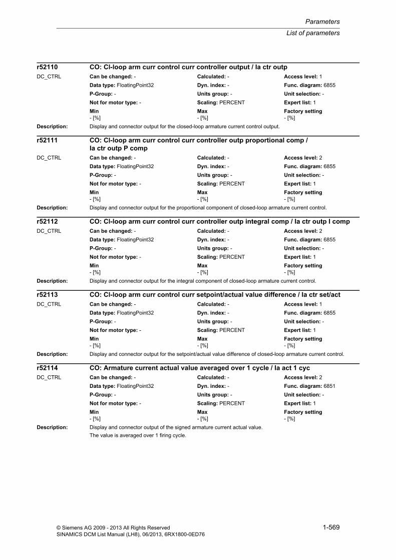
List of parameters
Parameters
1-569© Siemens AG 2009 - 2013 All Rights ReservedSINAMICS DCM List Manual (LH8), 06/2013, 6RX1800-0ED76
Description: Display and connector output for the closed-loop armature current control output.
Description: Display and connector output for the proportional component of closed-loop armature current control.
Description: Display and connector output for the integral component of closed-loop armature current control.
Description: Display and connector output for the setpoint/actual value difference of closed-loop armature current control.
Description: Display and connector output of the signed armature current actual value.
The value is averaged over 1 firing cycle.
r52110 CO: Cl-loop arm curr control curr controller output / Ia ctr outpDC_CTRL Can be changed: - Calculated: - Access level: 1
Data type: FloatingPoint32 Dyn. index: - Func. diagram: 6855
P-Group: - Units group: - Unit selection: -
Not for motor type: - Scaling: PERCENT Expert list: 1
Min Max Factory setting - [%] - [%] - [%]
r52111 CO: Cl-loop arm curr control curr controller outp proportional comp / Ia ctr outp P comp
DC_CTRL Can be changed: - Calculated: - Access level: 2
Data type: FloatingPoint32 Dyn. index: - Func. diagram: 6855
P-Group: - Units group: - Unit selection: -
Not for motor type: - Scaling: PERCENT Expert list: 1
Min Max Factory setting - [%] - [%] - [%]
r52112 CO: Cl-loop arm curr control curr controller outp integral comp / Ia ctr outp I compDC_CTRL Can be changed: - Calculated: - Access level: 2
Data type: FloatingPoint32 Dyn. index: - Func. diagram: 6855
P-Group: - Units group: - Unit selection: -
Not for motor type: - Scaling: PERCENT Expert list: 1
Min Max Factory setting - [%] - [%] - [%]
r52113 CO: Cl-loop arm curr control curr setpoint/actual value difference / Ia ctr set/actDC_CTRL Can be changed: - Calculated: - Access level: 1
Data type: FloatingPoint32 Dyn. index: - Func. diagram: 6855
P-Group: - Units group: - Unit selection: -
Not for motor type: - Scaling: PERCENT Expert list: 1
Min Max Factory setting - [%] - [%] - [%]
r52114 CO: Armature current actual value averaged over 1 cycle / Ia act 1 cycDC_CTRL Can be changed: - Calculated: - Access level: 2
Data type: FloatingPoint32 Dyn. index: - Func. diagram: 6851
P-Group: - Units group: - Unit selection: -
Not for motor type: - Scaling: PERCENT Expert list: 1
Min Max Factory setting - [%] - [%] - [%]

Parameters
List of parameters
1-570 © Siemens AG 2009 - 2013 All Rights ReservedSINAMICS DCM List Manual (LH8), 06/2013, 6RX1800-0ED76
Description: Display and connector output for the absolute value of the current controller actual value for closed-loop armature current control.
Description: Display and connector output for the absolute value of the internal armature current actual value.
The value is averaged over 1 firing cycle.
Description: Display and connector output for the signed internal armature current actual value.
The value is averaged between the centers of the firing intervals.
Description: Display and connector output for the absolute value of the current controller setpoint for closed-loop armature cur-rent control.
Dependency: Refer to: r50020
Description: Display and connector output for the current controller setpoint prior to absolute value generation for closed-loop armature current control.
r52115 CO: Cl-loop arm curr control curr controller actual value abs value / Ia ctr I_act absDC_CTRL Can be changed: - Calculated: - Access level: 1
Data type: FloatingPoint32 Dyn. index: - Func. diagram: 6855
P-Group: - Units group: - Unit selection: -
Not for motor type: - Scaling: PERCENT Expert list: 1
Min Max Factory setting - [%] - [%] - [%]
r52116 CO: Armature current actual value internal absolute value / A I_act int absDC_CTRL Can be changed: - Calculated: - Access level: 2
Data type: FloatingPoint32 Dyn. index: - Func. diagram: 6851
P-Group: - Units group: - Unit selection: -
Not for motor type: - Scaling: PERCENT Expert list: 1
Min Max Factory setting - [%] - [%] - [%]
r52117 CO: Armature current actual value internal signed / A I_act int signDC_CTRL Can be changed: - Calculated: - Access level: 2
Data type: FloatingPoint32 Dyn. index: - Func. diagram: 6851
P-Group: - Units group: - Unit selection: -
Not for motor type: - Scaling: PERCENT Expert list: 1
Min Max Factory setting - [%] - [%] - [%]
r52118 CO: Cl-loop arm curr control curr controller setpoint absolute value / Ia ctr I_set absDC_CTRL Can be changed: - Calculated: - Access level: 1
Data type: FloatingPoint32 Dyn. index: - Func. diagram: 6855
P-Group: - Units group: - Unit selection: -
Not for motor type: - Scaling: PERCENT Expert list: 1
Min Max Factory setting - [%] - [%] - [%]
r52119 CO: Cl-loop arm curr control curr controller setpoint / Ia ctr I_setDC_CTRL Can be changed: - Calculated: - Access level: 2
Data type: FloatingPoint32 Dyn. index: - Func. diagram: 6855
P-Group: - Units group: - Unit selection: -
Not for motor type: - Scaling: PERCENT Expert list: 1
Min Max Factory setting - [%] - [%] - [%]

List of parameters
Parameters
1-571© Siemens AG 2009 - 2013 All Rights ReservedSINAMICS DCM List Manual (LH8), 06/2013, 6RX1800-0ED76
Description: Display and connector output for the current controller setpoint before reduced gearbox stressing.
Description: Display and connector output for the armature current pre-control output.
Description: Display and connector output for the EMF actual value for armature current pre-control.
Note: 100% corresponds to p50078[0] * (3 * sqrt(2)) / Pi.
Description: Display and connector output for the signed unsmoothed EMF actual value.
Note: 100% corresponds to p50078[0] * (3 * sqrt(2)) / Pi.
Description: Display and connector output for the active power for a pure ohmic load (= r52126 * r52127).
The value is averaged over six firing cycles.
Note: This quantity is used for heating applications (rms value current control or rms value power control).
r52120 CO: Curr limitation arm curr setpoint before red gearbox stressing / Ia_set bef gearDC_CTRL Can be changed: - Calculated: - Access level: 1
Data type: FloatingPoint32 Dyn. index: - Func. diagram: 6845
P-Group: - Units group: - Unit selection: -
Not for motor type: - Scaling: PERCENT Expert list: 1
Min Max Factory setting - [%] - [%] - [%]
r52121 CO: Closed-loop armature current control pre-control output / Ia ctr prec outpDC_CTRL Can be changed: - Calculated: - Access level: 1
Data type: FloatingPoint32 Dyn. index: - Func. diagram: 6855
P-Group: - Units group: - Unit selection: -
Not for motor type: - Scaling: PERCENT Expert list: 1
Min Max Factory setting - [%] - [%] - [%]
r52122 CO: EMF actual value armature current pre-control / EMF act precDC_CTRL Can be changed: - Calculated: - Access level: 2
Data type: FloatingPoint32 Dyn. index: - Func. diagram: 6852, 6855
P-Group: - Units group: - Unit selection: -
Not for motor type: - Scaling: PERCENT Expert list: 1
Min Max Factory setting - [%] - [%] - [%]
r52123 CO: EMF actual value signed / EMF act signDC_CTRL Can be changed: - Calculated: - Access level: 2
Data type: FloatingPoint32 Dyn. index: - Func. diagram: 6852, 6902
P-Group: - Units group: - Unit selection: -
Not for motor type: - Scaling: PERCENT Expert list: 1
Min Max Factory setting - [%] - [%] - [%]
r52124 CO: Active power for a pure ohmic load / P_act ohm loadDC_CTRL Can be changed: - Calculated: - Access level: 2
Data type: FloatingPoint32 Dyn. index: - Func. diagram: 6902
P-Group: - Units group: - Unit selection: -
Not for motor type: - Scaling: PERCENT Expert list: 1
Min Max Factory setting - [%] - [%] - [%]

Parameters
List of parameters
1-572 © Siemens AG 2009 - 2013 All Rights ReservedSINAMICS DCM List Manual (LH8), 06/2013, 6RX1800-0ED76
Description: Display and connector output for the current controller setpoint after reduced gearbox stressing.
Description: Display and connector output for the rms value of the internal armature current actual value.
The value is averaged over 6 firing cycles, and referred to the rated device current (r50072[1]).
Description: Display and connector output for the rms value of the armature voltage.
The value is averaged over six firing cycles.
100 % corresponds to (3 * sqrt(2)) / Pi * p50078[0] = 1.35 * p50078[0] (= U_di0_rated)
Description: Displays the linearized firing angle.
Dependency: Refer to: p50600
Note: This parameter is calculated when Ua_set is fed into the gating unit.
-100 % corresponds to 180 degrees
+100% corresponds to 0 degrees
Description: Display and connector output for the armature current setpoint after speed-dependent current limitation.
r52125 CO: Curr limitation arm curr setpoint aft reduced gearbox stressing / Ia set aft gearDC_CTRL Can be changed: - Calculated: - Access level: 1
Data type: FloatingPoint32 Dyn. index: - Func. diagram: 6845
P-Group: - Units group: - Unit selection: -
Not for motor type: - Scaling: PERCENT Expert list: 1
Min Max Factory setting - [%] - [%] - [%]
r52126 CO: Armature current actual value rms value / Ia_act rmsDC_CTRL Can be changed: - Calculated: - Access level: 2
Data type: FloatingPoint32 Dyn. index: - Func. diagram: 6851
P-Group: - Units group: - Unit selection: -
Not for motor type: - Scaling: PERCENT Expert list: 1
Min Max Factory setting - [%] - [%] - [%]
r52127 CO: Armature voltage rms value / Ua_act rmsDC_CTRL Can be changed: - Calculated: - Access level: 2
Data type: FloatingPoint32 Dyn. index: - Func. diagram: 6902
P-Group: - Units group: - Unit selection: -
Not for motor type: - Scaling: PERCENT Expert list: 1
Min Max Factory setting - [%] - [%] - [%]
r52128 CO: Firing angle linearized / Firing angle linDC_CTRL Can be changed: - Calculated: - Access level: 2
Data type: FloatingPoint32 Dyn. index: - Func. diagram: 6858
P-Group: - Units group: - Unit selection: -
Not for motor type: - Scaling: PERCENT Expert list: 1
Min Max Factory setting - [%] - [%] - [%]
r52129 CO: n-dependent current limitation armature current setpoint limit / I_lim Ia set limDC_CTRL Can be changed: - Calculated: - Access level: 2
Data type: FloatingPoint32 Dyn. index: - Func. diagram: 8040
P-Group: - Units group: - Unit selection: -
Not for motor type: - Scaling: PERCENT Expert list: 1
Min Max Factory setting - [%] - [%] - [%]

List of parameters
Parameters
1-573© Siemens AG 2009 - 2013 All Rights ReservedSINAMICS DCM List Manual (LH8), 06/2013, 6RX1800-0ED76
Dependency: Refer to: p50109
Description: Display and connector output for the armature current setpoint after limitation by means of I2t monitoring as a per-centage of r50072[1].
Description: Display and connector output for the minimum positive armature current limit.
Description: Display and connector output for the maximum negative armature current limit.
Description: Display and connector output for the armature current controller setpoint before limitation (with additional setpoint).
Description: Display and connector output for the current controller setpoint before current limitation.
r52130 CO: I2t monitoring armature current setpoint after limitation / I2t Ia set n limDC_CTRL Can be changed: - Calculated: - Access level: 2
Data type: FloatingPoint32 Dyn. index: - Func. diagram: 8042
P-Group: - Units group: - Unit selection: -
Not for motor type: - Scaling: PERCENT Expert list: 1
Min Max Factory setting - [%] - [%] - [%]
r52131 CO: Current limitation minimum positive armature current limit / Ia lim pos minDC_CTRL Can be changed: - Calculated: - Access level: 2
Data type: FloatingPoint32 Dyn. index: - Func. diagram: 6840, 6845
P-Group: - Units group: - Unit selection: -
Not for motor type: - Scaling: PERCENT Expert list: 1
Min Max Factory setting - [%] - [%] - [%]
r52132 CO: Current limitation maximum negative armature current limit / Ia lim neg maxDC_CTRL Can be changed: - Calculated: - Access level: 2
Data type: FloatingPoint32 Dyn. index: - Func. diagram: 6840, 6845
P-Group: - Units group: - Unit selection: -
Not for motor type: - Scaling: PERCENT Expert list: 1
Min Max Factory setting - [%] - [%] - [%]
r52133 CO: Current limitation setpoint before limitation (with add_s) / Set bef lim w addDC_CTRL Can be changed: - Calculated: - Access level: 1
Data type: FloatingPoint32 Dyn. index: - Func. diagram: 6840, 8042
P-Group: - Units group: - Unit selection: -
Not for motor type: - Scaling: PERCENT Expert list: 1
Min Max Factory setting - [%] - [%] - [%]
r52134 CO: Speed limiting controller curr controller setp before limitation / Ia set bef limDC_CTRL Can be changed: - Calculated: - Access level: 1
Data type: FloatingPoint32 Dyn. index: - Func. diagram: 6835
P-Group: - Units group: - Unit selection: -
Not for motor type: - Scaling: PERCENT Expert list: 1
Min Max Factory setting - [%] - [%] - [%]

Parameters
List of parameters
1-574 © Siemens AG 2009 - 2013 All Rights ReservedSINAMICS DCM List Manual (LH8), 06/2013, 6RX1800-0ED76
Description: Display and connector output for the variable torque limiting defaults in torque direction II.
Dependency: Refer to: p50603, p50604
Note: Connector output r52135[0 to 6] is the inverse of p50603[0 to 6] and interconnected by default via connector input p50604[0 to 6].
Description: Display and connector output for the effective upper torque limit (maximum value) on the speed limiting controller.
Dependency: Refer to: r52137
Description: Display and connector output for the effective lower torque limit (minimum value) on the speed limiting controller.
Dependency: Refer to: r52136
Description: Display and connector output for the defaults for variable negative torque limiting.
Dependency: Refer to: p50606
Note: Connector output r52138[0 to 4] is the inverse of p50605[0 to 4]; it is interconnected by default via connector input p50606[0 to 4].
Description: Display and connector output for the torque setpoint.
r52135[0...6] CO: Current limitation default for torque direction II / Ia lim def t d IIDC_CTRL Can be changed: - Calculated: - Access level: 2
Data type: FloatingPoint32 Dyn. index: - Func. diagram: 6840
P-Group: - Units group: - Unit selection: -
Not for motor type: - Scaling: PERCENT Expert list: 1
Min Max Factory setting - [%] - [%] - [%]
r52136 CO: Speed limiting controller upper torque limit effective / n_lim t lim up maxDC_CTRL Can be changed: - Calculated: - Access level: 2
Data type: FloatingPoint32 Dyn. index: - Func. diagram: 6835
P-Group: - Units group: - Unit selection: -
Not for motor type: - Scaling: PERCENT Expert list: 1
Min Max Factory setting - [%] - [%] - [%]
r52137 CO: Speed limiting controller lower torque limit effective / n_lim t lim l minDC_CTRL Can be changed: - Calculated: - Access level: 2
Data type: FloatingPoint32 Dyn. index: - Func. diagram: 6835
P-Group: - Units group: - Unit selection: -
Not for motor type: - Scaling: PERCENT Expert list: 1
Min Max Factory setting - [%] - [%] - [%]
r52138[0...4] CO: Torque limiting negative default / Tqe lim neg defDC_CTRL Can be changed: - Calculated: - Access level: 2
Data type: FloatingPoint32 Dyn. index: - Func. diagram: 6825
P-Group: - Units group: - Unit selection: -
Not for motor type: - Scaling: PERCENT Expert list: 1
Min Max Factory setting - [%] - [%] - [%]
r52140 CO: Torque limiting torque setpoint / Tqe lim setDC_CTRL Can be changed: - Calculated: - Access level: 2
Data type: FloatingPoint32 Dyn. index: - Func. diagram: 6835
P-Group: - Units group: - Unit selection: -
Not for motor type: - Scaling: PERCENT Expert list: 1
Min Max Factory setting - [%] - [%] - [%]

List of parameters
Parameters
1-575© Siemens AG 2009 - 2013 All Rights ReservedSINAMICS DCM List Manual (LH8), 06/2013, 6RX1800-0ED76
Description: Display and connector output for the torque setpoint after limiting.
Description: Display and connector output for the torque actual value as a percentage of r50072[1] * p50102.
Description: Display and connector output for the minimum positive torque limit for the armature.
Description: Display and connector output for the maximum negative torque limit for the armature.
Description: Display and connector output for the torque setpoint before limiting (with additional setpoint).
r52141 CO: Torque limiting torque setpoint after limiting / T lim set aft limDC_CTRL Can be changed: - Calculated: - Access level: 1
Data type: FloatingPoint32 Dyn. index: - Func. diagram: 6830
P-Group: - Units group: - Unit selection: -
Not for motor type: - Scaling: PERCENT Expert list: 1
Min Max Factory setting - [%] - [%] - [%]
r52142 CO: Armature current actual value sensing torque actual value / A act val s tq actDC_CTRL Can be changed: - Calculated: - Access level: 2
Data type: FloatingPoint32 Dyn. index: - Func. diagram: 6851
P-Group: - Units group: - Unit selection: -
Not for motor type: - Scaling: PERCENT Expert list: 1
Min Max Factory setting - [%] - [%] - [%]
r52143 CO: Torque limiting armature torque limit min pos / T lim arm min posDC_CTRL Can be changed: - Calculated: - Access level: 2
Data type: FloatingPoint32 Dyn. index: - Func. diagram: 6830
P-Group: - Units group: - Unit selection: -
Not for motor type: - Scaling: PERCENT Expert list: 1
Min Max Factory setting - [%] - [%] - [%]
r52144 CO: Torque limiting armature torque limit max neg / T lim arm max negDC_CTRL Can be changed: - Calculated: - Access level: 2
Data type: FloatingPoint32 Dyn. index: - Func. diagram: 6830
P-Group: - Units group: - Unit selection: -
Not for motor type: - Scaling: PERCENT Expert list: 1
Min Max Factory setting - [%] - [%] - [%]
r52145 CO: Torque limiting setpoint before limiting (with add_s) / Set bef lim w addDC_CTRL Can be changed: - Calculated: - Access level: 1
Data type: FloatingPoint32 Dyn. index: - Func. diagram: 6830
P-Group: - Units group: - Unit selection: -
Not for motor type: - Scaling: PERCENT Expert list: 1
Min Max Factory setting - [%] - [%] - [%]

Parameters
List of parameters
1-576 © Siemens AG 2009 - 2013 All Rights ReservedSINAMICS DCM List Manual (LH8), 06/2013, 6RX1800-0ED76
Description: Display and connector output for the torque setpoint before limiting (without additional setpoint).
Description: Display and connector output for the speed controller's output value with friction and inertia compensation and addi-tional torque setpoint.
Description: Display and connector output for the torque actual value referenced to p50100 * p50102.
Description: Display and connector output for the setpoint change on the speed controller.
Dependency: Refer to: p50540, r52174
Description: Display and connector output for acceleration dependent upon setpoint/actual value difference.
In the case of the "Acceleration dependent upon setpoint/actual value difference" function, only the proportion of the speed controller's setpoint/actual value difference which has an absolute value in excess of the threshold (p50543) is switched through.
Dependency: Refer to: p50541, p50543
r52147 CO: Torque limiting setpoint before limiting (without add_s) / Set b lim w/o addDC_CTRL Can be changed: - Calculated: - Access level: 1
Data type: FloatingPoint32 Dyn. index: - Func. diagram: 6830, 6840
P-Group: - Units group: - Unit selection: -
Not for motor type: - Scaling: PERCENT Expert list: 1
Min Max Factory setting - [%] - [%] - [%]
r52148 CO: Speed controller torque setpoint / n_ctr tq setDC_CTRL Can be changed: - Calculated: - Access level: 1
Data type: FloatingPoint32 Dyn. index: - Func. diagram: 6815
P-Group: - Units group: - Unit selection: -
Not for motor type: - Scaling: PERCENT Expert list: 1
Min Max Factory setting - [%] - [%] - [%]
r52149 CO: Torque actual value in relation to p50100 * p50102 / Tqe act refDC_CTRL Can be changed: - Calculated: - Access level: 2
Data type: FloatingPoint32 Dyn. index: - Func. diagram: 6851
P-Group: - Units group: - Unit selection: -
Not for motor type: - Scaling: PERCENT Expert list: 1
Min Max Factory setting - [%] - [%] - [%]
r52150 CO: Speed controller setpoint change / n_ctr set chngDC_CTRL Can be changed: - Calculated: - Access level: 2
Data type: FloatingPoint32 Dyn. index: - Func. diagram: 6820
P-Group: - Units group: - Unit selection: -
Not for motor type: - Scaling: PERCENT Expert list: 1
Min Max Factory setting - [%] - [%] - [%]
r52152 CO: Speed controller setpoint/actual value difference output / Set/act dif outpDC_CTRL Can be changed: - Calculated: - Access level: 2
Data type: FloatingPoint32 Dyn. index: - Func. diagram: 6820
P-Group: - Units group: - Unit selection: -
Not for motor type: - Scaling: PERCENT Expert list: 1
Min Max Factory setting - [%] - [%] - [%]

List of parameters
Parameters
1-577© Siemens AG 2009 - 2013 All Rights ReservedSINAMICS DCM List Manual (LH8), 06/2013, 6RX1800-0ED76
Description: Display and connector output for the reference model for the speed controller.
Dependency: Refer to: p50237, p50238, p50239
Description: Display and connector output for the setpoint-actual value difference after the influence of the reference model for the speed controller.
Dependency: Refer to: p50621, p50622, p50623, p50624
Description: Display and connector output for the speed controller's output value.
Description: Display and connector output for the output value of the proportional component on the speed controller.
Description: Display and connector output for the integral component of the speed controller's output value.
r52154 CO: Speed controller reference model output / n_ctrl ref outpDC_CTRL Can be changed: - Calculated: - Access level: 2
Data type: FloatingPoint32 Dyn. index: - Func. diagram: 6812
P-Group: - Units group: - Unit selection: -
Not for motor type: - Scaling: PERCENT Expert list: 1
Min Max Factory setting - [%] - [%] - [%]
r52155 CO: Speed controller reference model setpoint-actual val difference / n_ctr ref set-actDC_CTRL Can be changed: - Calculated: - Access level: 2
Data type: FloatingPoint32 Dyn. index: - Func. diagram: 6812
P-Group: - Units group: - Unit selection: -
Not for motor type: - Scaling: PERCENT Expert list: 1
Min Max Factory setting - [%] - [%] - [%]
r52160 CO: Speed controller output value / n_ctr outp valDC_CTRL Can be changed: - Calculated: - Access level: 1
Data type: FloatingPoint32 Dyn. index: - Func. diagram: 6815
P-Group: - Units group: - Unit selection: -
Not for motor type: - Scaling: PERCENT Expert list: 1
Min Max Factory setting - [%] - [%] - [%]
r52161 CO: Speed controller proportional component output value / P comp outp valDC_CTRL Can be changed: - Calculated: - Access level: 2
Data type: FloatingPoint32 Dyn. index: - Func. diagram: 6815
P-Group: - Units group: - Unit selection: -
Not for motor type: - Scaling: PERCENT Expert list: 1
Min Max Factory setting - [%] - [%] - [%]
r52162 CO: Speed controller integral component output value / I_comp outp valDC_CTRL Can be changed: - Calculated: - Access level: 2
Data type: FloatingPoint32 Dyn. index: - Func. diagram: 6815
P-Group: - Units group: - Unit selection: -
Not for motor type: - Scaling: PERCENT Expert list: 1
Min Max Factory setting - [%] - [%] - [%]

Parameters
List of parameters
1-578 © Siemens AG 2009 - 2013 All Rights ReservedSINAMICS DCM List Manual (LH8), 06/2013, 6RX1800-0ED76
Description: Display and connector output of the speed setpoint/actual value difference used for the speed controller.
Dependency: Refer to: p50620
Description: Display and connector output for the result of the setpoint/actual value difference on the speed controller.
Dependency: Refer to: p50621, p50622, p50623, p50624
Note: The setpoint/actual value difference (r52165) results from setpoint 1 and 2 (p50621, p50622) and actual value 1 and 2 (p50623, p50624).
Description: Display and connector output of the selected speed actual value as an absolute value on the speed controller.
Description: Display and connector output of the selected speed actual value on the speed controller.
Description: Display and connector output for the negative output value of the derivative-action element.
Dependency: Refer to: p50205, p50206, p50627, r52169
r52164 CO: Speed controller setpoint/actual value difference / n_ctr set/act difDC_CTRL Can be changed: - Calculated: - Access level: 1
Data type: FloatingPoint32 Dyn. index: - Func. diagram: 6815, 6820
P-Group: - Units group: - Unit selection: -
Not for motor type: - Scaling: PERCENT Expert list: 1
Min Max Factory setting - [%] - [%] - [%]
r52165 CO: Speed controller setpoint/actual value difference / n_ctr set/act difDC_CTRL Can be changed: - Calculated: - Access level: 1
Data type: FloatingPoint32 Dyn. index: - Func. diagram: 6810
P-Group: - Units group: - Unit selection: -
Not for motor type: - Scaling: PERCENT Expert list: 1
Min Max Factory setting - [%] - [%] - [%]
r52166 CO: Speed controller actual value selection absolute value / Sel act absDC_CTRL Can be changed: - Calculated: - Access level: 2
Data type: FloatingPoint32 Dyn. index: - Func. diagram: 6810, 6815, 6825, 6900, 8040, 8046
P-Group: - Units group: - Unit selection: -
Not for motor type: - Scaling: PERCENT Expert list: 1
Min Max Factory setting - [%] - [%] - [%]
r52167 CO: Speed controller actual value selection / Act selDC_CTRL Can be changed: - Calculated: - Access level: 1
Data type: FloatingPoint32 Dyn. index: - Func. diagram: 6810
P-Group: - Units group: - Unit selection: -
Not for motor type: - Scaling: PERCENT Expert list: 1
Min Max Factory setting - [%] - [%] - [%]
r52168 CO: Derivative-action element negative output value / D elem neg outpDC_CTRL Can be changed: - Calculated: - Access level: 2
Data type: FloatingPoint32 Dyn. index: - Func. diagram: 6810
P-Group: - Units group: - Unit selection: -
Not for motor type: - Scaling: PERCENT Expert list: 1
Min Max Factory setting - [%] - [%] - [%]

List of parameters
Parameters
1-579© Siemens AG 2009 - 2013 All Rights ReservedSINAMICS DCM List Manual (LH8), 06/2013, 6RX1800-0ED76
Description: Display and connector output for the output value of the derivative-action element.
Dependency: Refer to: p50205, p50206, p50627, r52168
Description: Display and connector output for the speed setpoint after limiting.
Description: Display and connector output of the compensation output value for friction and inertia.
Dependency: Refer to: p50223
Note: If p50223 = 1:
This value is added to the speed controller's output.
Description: Display and connector output for the friction compensation output value.
Description: Display and connector output for the moment of inertia compensation output value.
Dependency: Refer to: p50697
Note: If p50697 = 1 signal:
This value is added to the friction and moment of inertia compensation output.
r52169 CO: Derivative-action element output value / D elem outpDC_CTRL Can be changed: - Calculated: - Access level: 2
Data type: FloatingPoint32 Dyn. index: - Func. diagram: 6810
P-Group: - Units group: - Unit selection: -
Not for motor type: - Scaling: PERCENT Expert list: 1
Min Max Factory setting - [%] - [%] - [%]
r52170 CO: RFG speed setpoint after limiting / RFG n_set aft limDC_CTRL Can be changed: - Calculated: - Access level: 1
Data type: FloatingPoint32 Dyn. index: - Func. diagram: 1720, 3155
P-Group: - Units group: - Unit selection: -
Not for motor type: - Scaling: PERCENT Expert list: 1
Min Max Factory setting - [%] - [%] - [%]
r52171 CO: Friction/inertia compensation output value / Comp outpDC_CTRL Can be changed: - Calculated: - Access level: 2
Data type: FloatingPoint32 Dyn. index: - Func. diagram: 6815, 6820
P-Group: - Units group: - Unit selection: -
Not for motor type: - Scaling: PERCENT Expert list: 1
Min Max Factory setting - [%] - [%] - [%]
r52172 CO: Friction compensation output value / Fric comp outpDC_CTRL Can be changed: - Calculated: - Access level: 2
Data type: FloatingPoint32 Dyn. index: - Func. diagram: 6820
P-Group: - Units group: - Unit selection: -
Not for motor type: - Scaling: PERCENT Expert list: 1
Min Max Factory setting - [%] - [%] - [%]
r52173 CO: Inertia compensation output value / Inert comp outpDC_CTRL Can be changed: - Calculated: - Access level: 2
Data type: FloatingPoint32 Dyn. index: - Func. diagram: 6820
P-Group: - Units group: - Unit selection: -
Not for motor type: - Scaling: PERCENT Expert list: 1
Min Max Factory setting - [%] - [%] - [%]

Parameters
List of parameters
1-580 © Siemens AG 2009 - 2013 All Rights ReservedSINAMICS DCM List Manual (LH8), 06/2013, 6RX1800-0ED76
Description: Display and connector output of the smoothed setpoint on the speed controller.
Description: Display and connector output for the droop output value on the speed controller.
Description: Display and connector output for output value of band-stop 1.
Dependency: Refer to: p50201, p50202, p50628
Description: Display and connector output for output value of band-stop 2.
Dependency: Refer to: p50203, p50204, p50629
Description: Display and connector output of the smoothed actual value on the speed controller.
r52174 CO: Speed controller setpoint smoothed / n_ctr set smoothDC_CTRL Can be changed: - Calculated: - Access level: 1
Data type: FloatingPoint32 Dyn. index: - Func. diagram: 6810, 6820
P-Group: - Units group: - Unit selection: -
Not for motor type: - Scaling: PERCENT Expert list: 1
Min Max Factory setting - [%] - [%] - [%]
r52176 CO: Speed controller droop output value / Droop outp valDC_CTRL Can be changed: - Calculated: - Access level: 2
Data type: FloatingPoint32 Dyn. index: - Func. diagram: 6805
P-Group: - Units group: - Unit selection: -
Not for motor type: - Scaling: PERCENT Expert list: 1
Min Max Factory setting - [%] - [%] - [%]
r52177 CO: Band-stop 1 output value / Band-st 1 outpDC_CTRL Can be changed: - Calculated: - Access level: 2
Data type: FloatingPoint32 Dyn. index: - Func. diagram: 6810
P-Group: - Units group: - Unit selection: -
Not for motor type: - Scaling: PERCENT Expert list: 1
Min Max Factory setting - [%] - [%] - [%]
r52178 CO: Band-stop 2 output value / Band-st 2 outpDC_CTRL Can be changed: - Calculated: - Access level: 2
Data type: FloatingPoint32 Dyn. index: - Func. diagram: 6810
P-Group: - Units group: - Unit selection: -
Not for motor type: - Scaling: PERCENT Expert list: 1
Min Max Factory setting - [%] - [%] - [%]
r52179 CO: Speed controller actual value smoothed / n_ctr act smDC_CTRL Can be changed: - Calculated: - Access level: 1
Data type: FloatingPoint32 Dyn. index: - Func. diagram: 6810
P-Group: - Units group: - Unit selection: -
Not for motor type: - Scaling: PERCENT Expert list: 1
Min Max Factory setting - [%] - [%] - [%]

List of parameters
Parameters
1-581© Siemens AG 2009 - 2013 All Rights ReservedSINAMICS DCM List Manual (LH8), 06/2013, 6RX1800-0ED76
Description: Display and connector output for the effective positive setpoint limit with "Limiting after ramp-function generator".
Description: Display and connector output for the effective negative setpoint limit with "Limiting after ramp-function generator".
Description: Display and connector output for the speed setpoint with "Limiting after ramp-function generator".
Description: Display and connector output for the default value of variable negative main setpoint limiting with index 0.
Dependency: Refer to: p50642
Note: The value represents the inversion of p50642[0].
Description: Display and connector output for the default value of variable negative main setpoint limiting with index 1.
Dependency: Refer to: p50642
Note: The value represents the inversion of p50642[1].
r52181 CO: RFG effective positive setpoint limit / RFG set lim posDC_CTRL Can be changed: - Calculated: - Access level: 2
Data type: FloatingPoint32 Dyn. index: - Func. diagram: 3155
P-Group: - Units group: - Unit selection: -
Not for motor type: - Scaling: PERCENT Expert list: 1
Min Max Factory setting - [%] - [%] - [%]
r52182 CO: RFG effective negative setpoint limit / RFG set lim negDC_CTRL Can be changed: - Calculated: - Access level: 2
Data type: FloatingPoint32 Dyn. index: - Func. diagram: 3155
P-Group: - Units group: - Unit selection: -
Not for motor type: - Scaling: PERCENT Expert list: 1
Min Max Factory setting - [%] - [%] - [%]
r52183 CO: RFG speed setpoint before limiting / RFG n_set bef limDC_CTRL Can be changed: - Calculated: - Access level: 1
Data type: FloatingPoint32 Dyn. index: - Func. diagram: 3155
P-Group: - Units group: - Unit selection: -
Not for motor type: - Scaling: PERCENT Expert list: 1
Min Max Factory setting - [%] - [%] - [%]
r52184 CO: Setpoint processing main setpoint lim neg default 0 / M set neg def 0DC_CTRL Can be changed: - Calculated: - Access level: 2
Data type: FloatingPoint32 Dyn. index: - Func. diagram: 3135
P-Group: - Units group: - Unit selection: -
Not for motor type: - Scaling: PERCENT Expert list: 1
Min Max Factory setting - [%] - [%] - [%]
r52185 CO: Setpoint processing main setpoint lim neg default 1 / M set neg def 1DC_CTRL Can be changed: - Calculated: - Access level: 2
Data type: FloatingPoint32 Dyn. index: - Func. diagram: 3135
P-Group: - Units group: - Unit selection: -
Not for motor type: - Scaling: PERCENT Expert list: 1
Min Max Factory setting - [%] - [%] - [%]

Parameters
List of parameters
1-582 © Siemens AG 2009 - 2013 All Rights ReservedSINAMICS DCM List Manual (LH8), 06/2013, 6RX1800-0ED76
Description: Display and connector output for the default value of variable negative main setpoint limiting with index 2.
Dependency: Refer to: p50642
Note: The value represents the inversion of p50642[2].
Description: Display and connector output for the default value of variable negative main setpoint limiting with index 3.
Dependency: Refer to: p50642
Note: The value represents the inversion of p50642[3].
Description: Display and connector output for the speed setpoint calculated by the ramp-function generator.
Description: Display and connector output for the rise of the ramp-function generator output in relation to the time set in p50542.
Dependency: Refer to: p50542
Description: Display and connector output for the setpoint before the ramp-function generator.
r52186 CO: Setpoint processing main setpoint lim neg default 2 / M set neg def 2DC_CTRL Can be changed: - Calculated: - Access level: 2
Data type: FloatingPoint32 Dyn. index: - Func. diagram: 3135
P-Group: - Units group: - Unit selection: -
Not for motor type: - Scaling: PERCENT Expert list: 1
Min Max Factory setting - [%] - [%] - [%]
r52187 CO: Setpoint processing main setpoint lim neg default 3 / M set neg def 3DC_CTRL Can be changed: - Calculated: - Access level: 2
Data type: FloatingPoint32 Dyn. index: - Func. diagram: 3135
P-Group: - Units group: - Unit selection: -
Not for motor type: - Scaling: PERCENT Expert list: 1
Min Max Factory setting - [%] - [%] - [%]
r52190 CO: RFG speed setpoint output / RFG n_set outpDC_CTRL Can be changed: - Calculated: - Access level: 1
Data type: FloatingPoint32 Dyn. index: - Func. diagram: 3150, 3151, 3152, 3155
P-Group: - Units group: - Unit selection: -
Not for motor type: - Scaling: PERCENT Expert list: 1
Min Max Factory setting - [%] - [%] - [%]
r52191 CO: RFG dy/dt rise in relation to p50542 / RFG dy/dt p50542DC_CTRL Can be changed: - Calculated: - Access level: 2
Data type: FloatingPoint32 Dyn. index: - Func. diagram: 3152
P-Group: - Units group: - Unit selection: -
Not for motor type: - Scaling: PERCENT Expert list: 1
Min Max Factory setting - [%] - [%] - [%]
r52192 CO: RFG setpoint before ramp-function generator / RFG set bef RFGDC_CTRL Can be changed: - Calculated: - Access level: 1
Data type: FloatingPoint32 Dyn. index: - Func. diagram: 3151, 3152
P-Group: - Units group: - Unit selection: -
Not for motor type: - Scaling: PERCENT Expert list: 1
Min Max Factory setting - [%] - [%] - [%]

List of parameters
Parameters
1-583© Siemens AG 2009 - 2013 All Rights ReservedSINAMICS DCM List Manual (LH8), 06/2013, 6RX1800-0ED76
Description: Display and connector output for the setpoint to the ramp-function generator.
Dependency: Refer to: p50648
Description: Display and connector output for the sum "main setpoint (limited) + additional setpoint" after setpoint reduction.
Dependency: Refer to: p51607, p51608, r52195
Note: Setpoint reduction is set via p51608 and activated/de-activated via binector input p51607.
Description: Display and connector output for the sum "main setpoint (limited) + additional setpoint" before setpoint reduction.
Dependency: Refer to: p51607, p51608, r52194
Note: Setpoint reduction is set via p51608 and activated/de-activated via binector input p51607.
Description: Display and connector output for the effective upper limit in the case of main setpoint limiting.
Description: Display and connector output for the effective lower limit in the case of main setpoint limiting.
r52193 CO: Setpoint processing output to ramp-function generator / Outp to RFGDC_CTRL Can be changed: - Calculated: - Access level: 1
Data type: FloatingPoint32 Dyn. index: - Func. diagram: 3135
P-Group: - Units group: - Unit selection: -
Not for motor type: - Scaling: PERCENT Expert list: 1
Min Max Factory setting - [%] - [%] - [%]
r52194 CO: Setpoint processing setpoint after reduction / Set after reducDC_CTRL Can be changed: - Calculated: - Access level: 1
Data type: FloatingPoint32 Dyn. index: - Func. diagram: 3135
P-Group: - Units group: - Unit selection: -
Not for motor type: - Scaling: PERCENT Expert list: 1
Min Max Factory setting - [%] - [%] - [%]
r52195 CO: Setpoint processing setpoint before reduction / Set before reducDC_CTRL Can be changed: - Calculated: - Access level: 1
Data type: FloatingPoint32 Dyn. index: - Func. diagram: 3135
P-Group: - Units group: - Unit selection: -
Not for motor type: - Scaling: PERCENT Expert list: 1
Min Max Factory setting - [%] - [%] - [%]
r52196 CO: Setpoint processing main setpoint upper limit effective / M set up lim effDC_CTRL Can be changed: - Calculated: - Access level: 2
Data type: FloatingPoint32 Dyn. index: - Func. diagram: 3135
P-Group: - Units group: - Unit selection: -
Not for motor type: - Scaling: PERCENT Expert list: 1
Min Max Factory setting - [%] - [%] - [%]
r52197 CO: Setpoint processing main setpoint lower limit effective / M set low lim effDC_CTRL Can be changed: - Calculated: - Access level: 2
Data type: FloatingPoint32 Dyn. index: - Func. diagram: 3135
P-Group: - Units group: - Unit selection: -
Not for motor type: - Scaling: PERCENT Expert list: 1
Min Max Factory setting - [%] - [%] - [%]

Parameters
List of parameters
1-584 © Siemens AG 2009 - 2013 All Rights ReservedSINAMICS DCM List Manual (LH8), 06/2013, 6RX1800-0ED76
Description: Display and connector output for the main setpoint before setpoint limiting.
Description: Display and connector output for the sum of all creep setpoints (p504441[0 to 7]).
Dependency: Refer to: p50440, p50441
Description: Display and connector output for the sum of all jog setpoints (p50436[0 to 7]).
Dependency: Refer to: p50435, p50436
Description: Display and connector output for the square-wave generator.
Dependency: Refer to: p50480, p50481, p50482, p50483
Description: Display and connector output for the sum of all fixed setpoints (p50431[0 to 7]).
Dependency: Refer to: p50430, p50431
r52198 CO: Setpoint processing main setpoint before limiting / M_setp bef limDC_CTRL Can be changed: - Calculated: - Access level: 1
Data type: FloatingPoint32 Dyn. index: - Func. diagram: 3135
P-Group: - Units group: - Unit selection: -
Not for motor type: - Scaling: PERCENT Expert list: 1
Min Max Factory setting - [%] - [%] - [%]
r52201 CO: Creep setpoint output / Creep set outpDC_CTRL Can be changed: - Calculated: - Access level: 2
Data type: FloatingPoint32 Dyn. index: - Func. diagram: 3130
P-Group: - Units group: - Unit selection: -
Not for motor type: - Scaling: PERCENT Expert list: 1
Min Max Factory setting - [%] - [%] - [%]
r52202 CO: Jog setpoint output / Jog set outpDC_CTRL Can be changed: - Calculated: - Access level: 2
Data type: FloatingPoint32 Dyn. index: - Func. diagram: 3125
P-Group: - Units group: - Unit selection: -
Not for motor type: - Scaling: PERCENT Expert list: 1
Min Max Factory setting - [%] - [%] - [%]
r52203 CO: Oscillation square-wave generator setpoint / Oscill sq-w genDC_CTRL Can be changed: - Calculated: - Access level: 2
Data type: FloatingPoint32 Dyn. index: - Func. diagram: 3120
P-Group: - Units group: - Unit selection: -
Not for motor type: - Scaling: PERCENT Expert list: 1
Min Max Factory setting - [%] - [%] - [%]
r52204 CO: Fixed setpoint output / Fix set outpDC_CTRL Can be changed: - Calculated: - Access level: 2
Data type: FloatingPoint32 Dyn. index: - Func. diagram: 3115
P-Group: - Units group: - Unit selection: -
Not for motor type: - Scaling: PERCENT Expert list: 1
Min Max Factory setting - [%] - [%] - [%]
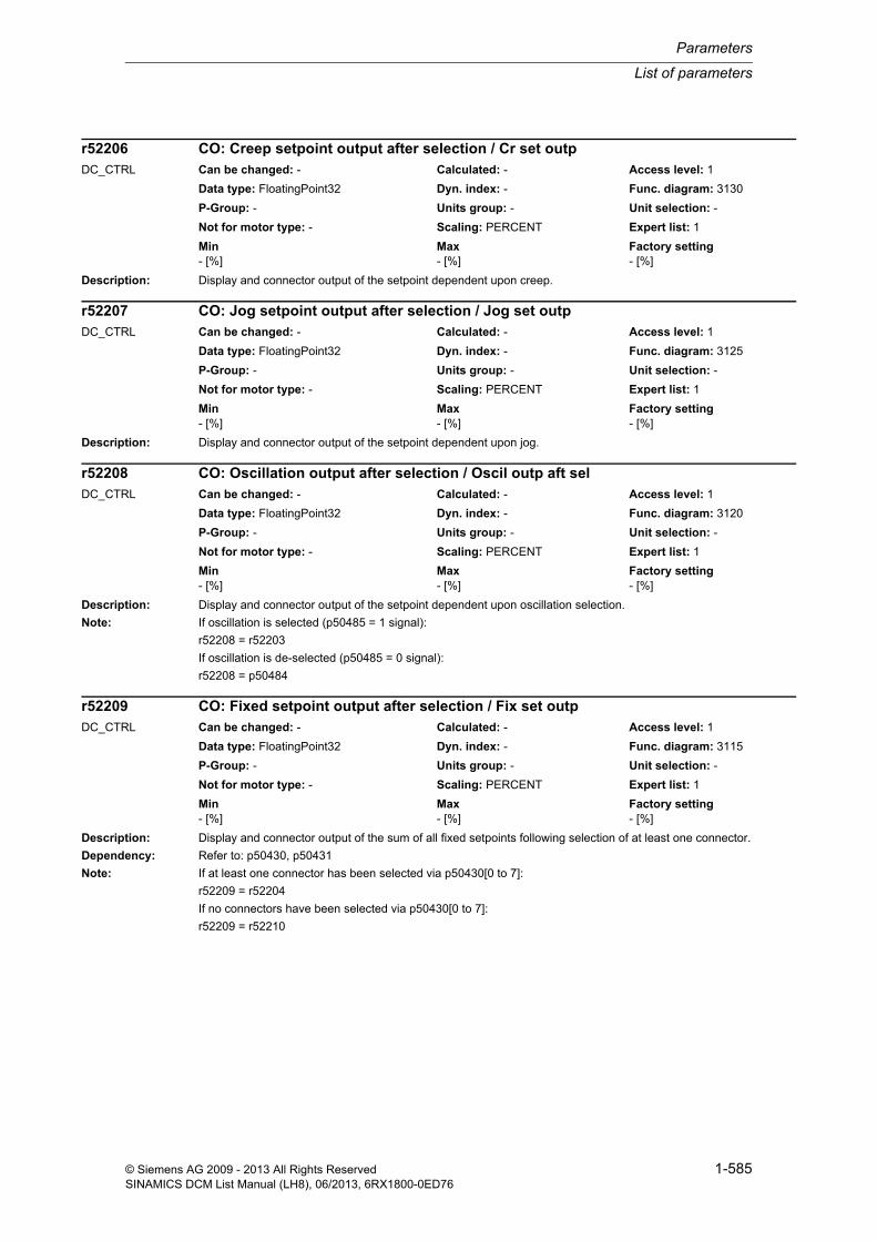
List of parameters
Parameters
1-585© Siemens AG 2009 - 2013 All Rights ReservedSINAMICS DCM List Manual (LH8), 06/2013, 6RX1800-0ED76
Description: Display and connector output of the setpoint dependent upon creep.
Description: Display and connector output of the setpoint dependent upon jog.
Description: Display and connector output of the setpoint dependent upon oscillation selection.
Note: If oscillation is selected (p50485 = 1 signal):
r52208 = r52203
If oscillation is de-selected (p50485 = 0 signal):
r52208 = p50484
Description: Display and connector output of the sum of all fixed setpoints following selection of at least one connector.
Dependency: Refer to: p50430, p50431
Note: If at least one connector has been selected via p50430[0 to 7]:
r52209 = r52204
If no connectors have been selected via p50430[0 to 7]:
r52209 = r52210
r52206 CO: Creep setpoint output after selection / Cr set outpDC_CTRL Can be changed: - Calculated: - Access level: 1
Data type: FloatingPoint32 Dyn. index: - Func. diagram: 3130
P-Group: - Units group: - Unit selection: -
Not for motor type: - Scaling: PERCENT Expert list: 1
Min Max Factory setting - [%] - [%] - [%]
r52207 CO: Jog setpoint output after selection / Jog set outpDC_CTRL Can be changed: - Calculated: - Access level: 1
Data type: FloatingPoint32 Dyn. index: - Func. diagram: 3125
P-Group: - Units group: - Unit selection: -
Not for motor type: - Scaling: PERCENT Expert list: 1
Min Max Factory setting - [%] - [%] - [%]
r52208 CO: Oscillation output after selection / Oscil outp aft selDC_CTRL Can be changed: - Calculated: - Access level: 1
Data type: FloatingPoint32 Dyn. index: - Func. diagram: 3120
P-Group: - Units group: - Unit selection: -
Not for motor type: - Scaling: PERCENT Expert list: 1
Min Max Factory setting - [%] - [%] - [%]
r52209 CO: Fixed setpoint output after selection / Fix set outpDC_CTRL Can be changed: - Calculated: - Access level: 1
Data type: FloatingPoint32 Dyn. index: - Func. diagram: 3115
P-Group: - Units group: - Unit selection: -
Not for motor type: - Scaling: PERCENT Expert list: 1
Min Max Factory setting - [%] - [%] - [%]

Parameters
List of parameters
1-586 © Siemens AG 2009 - 2013 All Rights ReservedSINAMICS DCM List Manual (LH8), 06/2013, 6RX1800-0ED76
Description: Display and connector output for the signals interconnected and inverted via connector input p50632[0 to 3].
Index: [0] = Signal p50632[0] inverted[1] = Signal p50632[1] inverted[2] = Signal p50632[2] inverted[3] = Signal p50632[3] inverted
Description: Display and connector output for the fixed setpoint after intervention from the advanced operator panel 30 (AOP30).
Dependency: Refer to: p50433
Description: Display and connector output on the motorized potentiometer.
Description: Display and connector output of the dy/dt output on the motorized potentiometer.
Description: Display and connector output of the setpoint on the motorized potentiometer.
r52210[0...3] CO: RFG positive limiting inverted after RFG / RFG pos lim invDC_CTRL Can be changed: - Calculated: - Access level: 2
Data type: FloatingPoint32 Dyn. index: - Func. diagram: 3155
P-Group: - Units group: - Unit selection: -
Not for motor type: - Scaling: PERCENT Expert list: 1
Min Max Factory setting - [%] - [%] - [%]
r52211 CO: Fixed setpoint output after AOP30 / Fix set outp AOPDC_CTRL Can be changed: - Calculated: - Access level: 1
Data type: FloatingPoint32 Dyn. index: - Func. diagram: 3113
P-Group: - Units group: - Unit selection: -
Not for motor type: - Scaling: PERCENT Expert list: 1
Min Max Factory setting - [%] - [%] - [%]
r52240 CO: Motorized potentiometer output / MotP outpDC_CTRL Can be changed: - Calculated: - Access level: 2
Data type: FloatingPoint32 Dyn. index: - Func. diagram: 3110
P-Group: - Units group: - Unit selection: -
Not for motor type: - Scaling: PERCENT Expert list: 1
Min Max Factory setting - [%] - [%] - [%]
r52241 CO: Motorized potentiometer output dy/dt / MotP outp dy/dtDC_CTRL Can be changed: - Calculated: - Access level: 2
Data type: FloatingPoint32 Dyn. index: - Func. diagram: 3110
P-Group: - Units group: - Unit selection: -
Not for motor type: - Scaling: PERCENT Expert list: 1
Min Max Factory setting - [%] - [%] - [%]
r52242 CO: Motorized potentiometer setpoint / MotP setDC_CTRL Can be changed: - Calculated: - Access level: 2
Data type: FloatingPoint32 Dyn. index: - Func. diagram: 3110
P-Group: - Units group: - Unit selection: -
Not for motor type: - Scaling: PERCENT Expert list: 1
Min Max Factory setting - [%] - [%] - [%]

List of parameters
Parameters
1-587© Siemens AG 2009 - 2013 All Rights ReservedSINAMICS DCM List Manual (LH8), 06/2013, 6RX1800-0ED76
Description: Display and connector output for the field firing angle after limiting by the auto-reversing stage.
Description: Displays the field firing angle before limiting by the auto-reversing stage.
Description: Display and connector output of the output value from pre-control and the field current controller.
Description: Display and connector output for the output in the case of closed-loop field current control.
Description: Display and connector output for the proportional component in the case of closed-loop field current control.
r52250 CO: Field firing angle after limiting / Fir ang aft limDC_CTRL Can be changed: - Calculated: - Access level: 1
Data type: FloatingPoint32 Dyn. index: - Func. diagram: 6915
P-Group: - Units group: - Unit selection: -
Not for motor type: - Scaling: PERCENT Expert list: 1
Min Max Factory setting - [%] - [%] - [%]
r52251 CO: Field firing angle before limiting / Fir ang bef limDC_CTRL Can be changed: - Calculated: - Access level: 1
Data type: FloatingPoint32 Dyn. index: - Func. diagram: 6915
P-Group: - Units group: - Unit selection: -
Not for motor type: - Scaling: PERCENT Expert list: 1
Min Max Factory setting - [%] - [%] - [%]
r52252 CO: Cl-loop field curr ctrl prectr and field curr controller output / If_ctr prec+ctrlDC_CTRL Can be changed: - Calculated: - Access level: 1
Data type: FloatingPoint32 Dyn. index: - Func. diagram: 6910
P-Group: - Units group: - Unit selection: -
Not for motor type: - Scaling: PERCENT Expert list: 1
Min Max Factory setting - [%] - [%] - [%]
r52260 CO: Closed-loop field current control current controller output / If_ctr I_ctr outpDC_CTRL Can be changed: - Calculated: - Access level: 1
Data type: FloatingPoint32 Dyn. index: - Func. diagram: 6910
P-Group: - Units group: - Unit selection: -
Not for motor type: - Scaling: PERCENT Expert list: 1
Min Max Factory setting - [%] - [%] - [%]
r52261 CO: Cl-loop field curr control curr controller proportional comp / If_ctr I_ctr P comDC_CTRL Can be changed: - Calculated: - Access level: 2
Data type: FloatingPoint32 Dyn. index: - Func. diagram: 6910
P-Group: - Units group: - Unit selection: -
Not for motor type: - Scaling: PERCENT Expert list: 1
Min Max Factory setting - [%] - [%] - [%]
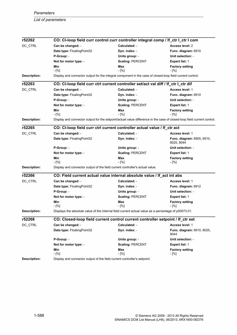
Parameters
List of parameters
1-588 © Siemens AG 2009 - 2013 All Rights ReservedSINAMICS DCM List Manual (LH8), 06/2013, 6RX1800-0ED76
Description: Display and connector output for the integral component in the case of closed-loop field current control.
Description: Display and connector output for the setpoint/actual value difference in the case of closed-loop field current control.
Description: Display and connector output of the field current controller's actual value.
Description: Displays the absolute value of the internal field current actual value as a percentage of p50073.01.
Description: Display and connector output of the field current controller's setpoint.
r52262 CO: Cl-loop field curr control curr controller integral comp / If_ctr I_ctr I comDC_CTRL Can be changed: - Calculated: - Access level: 2
Data type: FloatingPoint32 Dyn. index: - Func. diagram: 6910
P-Group: - Units group: - Unit selection: -
Not for motor type: - Scaling: PERCENT Expert list: 1
Min Max Factory setting - [%] - [%] - [%]
r52263 CO: Cl-loop field curr ctrl current controller set/act val diff / If_ctr I_ctr difDC_CTRL Can be changed: - Calculated: - Access level: 1
Data type: FloatingPoint32 Dyn. index: - Func. diagram: 6910
P-Group: - Units group: - Unit selection: -
Not for motor type: - Scaling: PERCENT Expert list: 1
Min Max Factory setting - [%] - [%] - [%]
r52265 CO: Cl-loop field curr ctrl current controller actual value / If_ctr actDC_CTRL Can be changed: - Calculated: - Access level: 1
Data type: FloatingPoint32 Dyn. index: - Func. diagram: 6905, 6910, 8025, 8044
P-Group: - Units group: - Unit selection: -
Not for motor type: - Scaling: PERCENT Expert list: 1
Min Max Factory setting - [%] - [%] - [%]
r52266 CO: Field current actual value internal absolute value / If_act int absDC_CTRL Can be changed: - Calculated: - Access level: 1
Data type: FloatingPoint32 Dyn. index: - Func. diagram: 6912
P-Group: - Units group: - Unit selection: -
Not for motor type: - Scaling: PERCENT Expert list: 1
Min Max Factory setting - [%] - [%] - [%]
r52268 CO: Closed-loop field current control current controller setpoint / If_ctr setDC_CTRL Can be changed: - Calculated: - Access level: 1
Data type: FloatingPoint32 Dyn. index: - Func. diagram: 6910, 8025, 8044
P-Group: - Units group: - Unit selection: -
Not for motor type: - Scaling: PERCENT Expert list: 1
Min Max Factory setting - [%] - [%] - [%]

List of parameters
Parameters
1-589© Siemens AG 2009 - 2013 All Rights ReservedSINAMICS DCM List Manual (LH8), 06/2013, 6RX1800-0ED76
Description: Display and connector output of pre-control for closed-loop field current control.
Description: Display and connector output for the upper limit of the field current setpoint.
Dependency: Refer to: r50073, p50102, p50613
Description: Display and connector output for the lower limit of the field current setpoint.
Dependency: Refer to: p50103, p50614
Description: Display and connector output for the field current setpoint after field current setpoint limiting.
Dependency: Refer to: p50611
Description: Display and connector output for the field current setpoint before field current setpoint limiting.
Dependency: Refer to: p50611
r52271 CO: Closed-loop field current control pre-control output / If_ctr prec outpDC_CTRL Can be changed: - Calculated: - Access level: 1
Data type: FloatingPoint32 Dyn. index: - Func. diagram: 6910
P-Group: - Units group: - Unit selection: -
Not for motor type: - Scaling: PERCENT Expert list: 1
Min Max Factory setting - [%] - [%] - [%]
r52273 CO: Field current setpoint limiting upper limit output / If lim up limDC_CTRL Can be changed: - Calculated: - Access level: 2
Data type: FloatingPoint32 Dyn. index: - Func. diagram: 6905
P-Group: - Units group: - Unit selection: -
Not for motor type: - Scaling: PERCENT Expert list: 1
Min Max Factory setting - [%] - [%] - [%]
r52274 CO: Field current setpoint limiting lower limit output / If lim low limDC_CTRL Can be changed: - Calculated: - Access level: 2
Data type: FloatingPoint32 Dyn. index: - Func. diagram: 6905
P-Group: - Units group: - Unit selection: -
Not for motor type: - Scaling: PERCENT Expert list: 1
Min Max Factory setting - [%] - [%] - [%]
r52275 CO: Field current setpoint limiting output after limiting / If lim outp limDC_CTRL Can be changed: - Calculated: - Access level: 1
Data type: FloatingPoint32 Dyn. index: - Func. diagram: 6905, 6910
P-Group: - Units group: - Unit selection: -
Not for motor type: - Scaling: PERCENT Expert list: 1
Min Max Factory setting - [%] - [%] - [%]
r52276 CO: Field current setpoint limiting output before limiting / If lim outpDC_CTRL Can be changed: - Calculated: - Access level: 1
Data type: FloatingPoint32 Dyn. index: - Func. diagram: 6905
P-Group: - Units group: - Unit selection: -
Not for motor type: - Scaling: PERCENT Expert list: 1
Min Max Factory setting - [%] - [%] - [%]

Parameters
List of parameters
1-590 © Siemens AG 2009 - 2013 All Rights ReservedSINAMICS DCM List Manual (LH8), 06/2013, 6RX1800-0ED76
Description: Display and connector output from pre-control and EMF controller after selection.
If p50081 = 0:
--> r52277 = 100%
If p50081 = 1:
--> r52277 = Sum of EMF controller and EMF pre-control outputs
Dependency: Refer to: p50081
Description: Display and connector output of the sum of the outputs from EMF pre-control and the EMF controller.
Description: Display and connector output on the EMF controller.
Description: Display and connector output of the proportional component on the EMF controller.
Description: Display and connector output of the integral component on the EMF controller.
r52277 CO: EMF controller pre-control and controller output after selection / EMF prec+ctrl sel
DC_CTRL Can be changed: - Calculated: - Access level: 1
Data type: FloatingPoint32 Dyn. index: - Func. diagram: 6900
P-Group: - Units group: - Unit selection: -
Not for motor type: - Scaling: - Expert list: 1
Min Max Factory setting - [%] - [%] - [%]
r52278 CO: EMF controller pre-control and controller output / EMF prec+ctrl outpDC_CTRL Can be changed: - Calculated: - Access level: 1
Data type: FloatingPoint32 Dyn. index: - Func. diagram: 6900
P-Group: - Units group: - Unit selection: -
Not for motor type: - Scaling: - Expert list: 1
Min Max Factory setting - [%] - [%] - [%]
r52280 CO: EMF controller output / EMF ctr outpDC_CTRL Can be changed: - Calculated: - Access level: 1
Data type: FloatingPoint32 Dyn. index: - Func. diagram: 6900
P-Group: - Units group: - Unit selection: -
Not for motor type: - Scaling: - Expert list: 1
Min Max Factory setting - [%] - [%] - [%]
r52281 CO: EMF controller proportional component output / EMF ctr P com outpDC_CTRL Can be changed: - Calculated: - Access level: 2
Data type: FloatingPoint32 Dyn. index: - Func. diagram: 6900
P-Group: - Units group: - Unit selection: -
Not for motor type: - Scaling: - Expert list: 1
Min Max Factory setting - [%] - [%] - [%]
r52282 CO: EMF controller integral component output / EMF ctr I com outpDC_CTRL Can be changed: - Calculated: - Access level: 2
Data type: FloatingPoint32 Dyn. index: - Func. diagram: 6900
P-Group: - Units group: - Unit selection: -
Not for motor type: - Scaling: - Expert list: 1
Min Max Factory setting - [%] - [%] - [%]

List of parameters
Parameters
1-591© Siemens AG 2009 - 2013 All Rights ReservedSINAMICS DCM List Manual (LH8), 06/2013, 6RX1800-0ED76
Description: Display and connector output of the setpoint/actual value difference on the EMF controller.
Description: Display and connector output of the setpoint/actual value difference after droop on the EMF controller.
Description: Display and connector output for the absolute value of the actual value on the EMF controller.
Dependency: Refer to: p50616
Note: A value of 100% corresponds to p50078[0] * (3 * sqrt(2)) / Pi.
Description: Displays the absolute value of the EMF actual value averaged over the last 3 firing periods (r52287).
Dependency: Refer to: r52287
Note: 100% corresponds to p50078[0] * (3 * sqrt(2)) / Pi
Description: Displays the signed EMF actual value averaged over the last 3 firing periods.
Note: 100% corresponds to p50078[0] * (3 * sqrt(2)) / Pi
r52283 CO: EMF controller setpoint/actual value difference / EMF ctr difDC_CTRL Can be changed: - Calculated: - Access level: 1
Data type: FloatingPoint32 Dyn. index: - Func. diagram: 6900
P-Group: - Units group: - Unit selection: -
Not for motor type: - Scaling: PERCENT Expert list: 1
Min Max Factory setting - [%] - [%] - [%]
r52284 CO: EMF controller setpoint/actual value difference after droop / EMF ctr dif droopDC_CTRL Can be changed: - Calculated: - Access level: 1
Data type: FloatingPoint32 Dyn. index: - Func. diagram: 6900
P-Group: - Units group: - Unit selection: -
Not for motor type: - Scaling: PERCENT Expert list: 1
Min Max Factory setting - [%] - [%] - [%]
r52285 CO: EMF controller actual value / EMF ctr actDC_CTRL Can be changed: - Calculated: - Access level: 1
Data type: FloatingPoint32 Dyn. index: - Func. diagram: 6900
P-Group: - Units group: - Unit selection: -
Not for motor type: - Scaling: PERCENT Expert list: 1
Min Max Factory setting - [%] - [%] - [%]
r52286 CO: Average absolute value of EMF actual value / EMF act abs avgDC_CTRL Can be changed: - Calculated: - Access level: 2
Data type: FloatingPoint32 Dyn. index: - Func. diagram: 6902
P-Group: - Units group: - Unit selection: -
Not for motor type: - Scaling: PERCENT Expert list: 1
Min Max Factory setting - [%] - [%] - [%]
r52287 CO: Average EMF actual value / EMF act avgDC_CTRL Can be changed: - Calculated: - Access level: 2
Data type: FloatingPoint32 Dyn. index: - Func. diagram: 6810, 6902, 8046
P-Group: - Units group: - Unit selection: -
Not for motor type: - Scaling: PERCENT Expert list: 1
Min Max Factory setting - [%] - [%] - [%]

Parameters
List of parameters
1-592 © Siemens AG 2009 - 2013 All Rights ReservedSINAMICS DCM List Manual (LH8), 06/2013, 6RX1800-0ED76
Description: Display and connector output for the absolute value of the setpoint on the EMF controller.
Dependency: Refer to: p50615
Note: A value of 100% corresponds to p50078[0] * (3 * sqrt(2)) / Pi.
Description: Display and connector output for the absolute value of the setpoint on the EMF controller.
Dependency: Refer to: r50039, p50100, p50101, p50110
Note: A value of 100% corresponds to p50078[0] * (3 * sqrt(2)) / Pi.
Description: Display and connector output of the motor flux in the case of closed-loop field current control.
The value is a percentage of p50102.
Description: Display and connector output for the actual value of the armature voltage as an absolute value.
Dependency: Refer to: r52292
Note: 100% corresponds to p50078[0] * (3 * sqrt(2)) / Pi
r52288 CO: EMF controller setpoint / EMF ctr setDC_CTRL Can be changed: - Calculated: - Access level: 1
Data type: FloatingPoint32 Dyn. index: - Func. diagram: 6900
P-Group: - Units group: - Unit selection: -
Not for motor type: - Scaling: PERCENT Expert list: 1
Min Max Factory setting - [%] - [%] - [%]
r52289 CO: EMF controller setpoint absolute value / EMF ctr set absDC_CTRL Can be changed: - Calculated: - Access level: 1
Data type: FloatingPoint32 Dyn. index: - Func. diagram: 6900
P-Group: - Units group: - Unit selection: -
Not for motor type: - Scaling: PERCENT Expert list: 1
Min Max Factory setting - [%] - [%] - [%]
r52290 CO: Closed-loop field current control motor flux output / If ctr motor fluxDC_CTRL Can be changed: - Calculated: - Access level: 2
Data type: FloatingPoint32 Dyn. index: - Func. diagram: 6830, 6835, 6851, 6910
P-Group: - Units group: - Unit selection: -
Not for motor type: - Scaling: PERCENT Expert list: 1
Min Max Factory setting - [%] - [%] - [%]
r52291 CO: Armature voltage actual value absolute value / Ua act absDC_CTRL Can be changed: - Calculated: - Access level: 2
Data type: FloatingPoint32 Dyn. index: - Func. diagram: 6902
P-Group: - Units group: - Unit selection: -
Not for motor type: - Scaling: PERCENT Expert list: 1
Min Max Factory setting - [%] - [%] - [%]

List of parameters
Parameters
1-593© Siemens AG 2009 - 2013 All Rights ReservedSINAMICS DCM List Manual (LH8), 06/2013, 6RX1800-0ED76
Description: Display and connector output for the signed actual value of the armature voltage.
Dependency: Refer to: r52291
Note: 100% corresponds to p50078[0] * (3 * sqrt(2)) / Pi
Description: Display and connector output for pre-control on the EMF controller.
Dependency: Refer to: p50273
Description: Display and connector output for the EMF setpoint reduction.
Dependency: Refer to: p50287, p50288
Description: Display and connector output for the actual value of the field voltage as an absolute value.
Dependency: Refer to: r52296
Note: 100% corresponds to p50078[1] * (3 * sqrt(2)) / Pi.
Description: Display and connector output for the signed actual value of the field voltage.
Dependency: Refer to: r52295
r52292 CO: Armature voltage signed actual value / Ua act signedDC_CTRL Can be changed: - Calculated: - Access level: 2
Data type: FloatingPoint32 Dyn. index: - Func. diagram: 6902
P-Group: - Units group: - Unit selection: -
Not for motor type: - Scaling: PERCENT Expert list: 1
Min Max Factory setting - [%] - [%] - [%]
r52293 CO: EMF controller pre-control output / EMF ctr prec outpDC_CTRL Can be changed: - Calculated: - Access level: 1
Data type: FloatingPoint32 Dyn. index: - Func. diagram: 6900, 6910
P-Group: - Units group: - Unit selection: -
Not for motor type: - Scaling: PERCENT Expert list: 1
Min Max Factory setting - [%] - [%] - [%]
r52294 CO: EMF setpoint reduction output / EMF setp_red outpDC_CTRL Can be changed: - Calculated: - Access level: 2
Data type: FloatingPoint32 Dyn. index: - Func. diagram: 6895
P-Group: - Units group: - Unit selection: -
Not for motor type: - Scaling: PERCENT Expert list: 1
Min Max Factory setting - [%] - [%] - [%]
r52295 CO: Field voltage actual value absolute value / Uf act absDC_CTRL Can be changed: - Calculated: - Access level: 2
Data type: FloatingPoint32 Dyn. index: - Func. diagram: 6902
P-Group: - Units group: - Unit selection: -
Not for motor type: - Scaling: PERCENT Expert list: 1
Min Max Factory setting - [%] - [%] - [%]
r52296 CO: Field voltage actual value signed / Uf act val signDC_CTRL Can be changed: - Calculated: - Access level: 2
Data type: FloatingPoint32 Dyn. index: - Func. diagram: 6902
P-Group: - Units group: - Unit selection: -
Not for motor type: - Scaling: PERCENT Expert list: 1
Min Max Factory setting - [%] - [%] - [%]
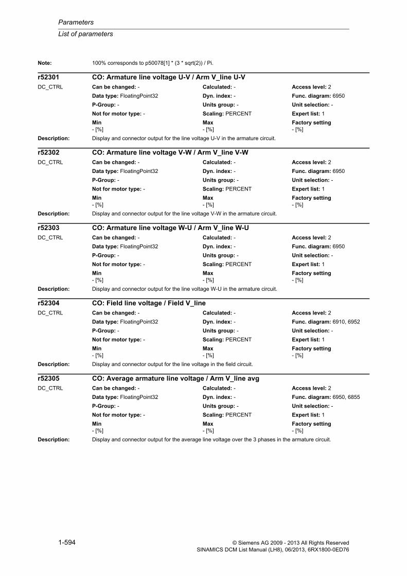
Parameters
List of parameters
1-594 © Siemens AG 2009 - 2013 All Rights ReservedSINAMICS DCM List Manual (LH8), 06/2013, 6RX1800-0ED76
Note: 100% corresponds to p50078[1] * (3 * sqrt(2)) / Pi.
Description: Display and connector output for the line voltage U-V in the armature circuit.
Description: Display and connector output for the line voltage V-W in the armature circuit.
Description: Display and connector output for the line voltage W-U in the armature circuit.
Description: Display and connector output for the line voltage in the field circuit.
Description: Display and connector output for the average line voltage over the 3 phases in the armature circuit.
r52301 CO: Armature line voltage U-V / Arm V_line U-VDC_CTRL Can be changed: - Calculated: - Access level: 2
Data type: FloatingPoint32 Dyn. index: - Func. diagram: 6950
P-Group: - Units group: - Unit selection: -
Not for motor type: - Scaling: PERCENT Expert list: 1
Min Max Factory setting - [%] - [%] - [%]
r52302 CO: Armature line voltage V-W / Arm V_line V-WDC_CTRL Can be changed: - Calculated: - Access level: 2
Data type: FloatingPoint32 Dyn. index: - Func. diagram: 6950
P-Group: - Units group: - Unit selection: -
Not for motor type: - Scaling: PERCENT Expert list: 1
Min Max Factory setting - [%] - [%] - [%]
r52303 CO: Armature line voltage W-U / Arm V_line W-UDC_CTRL Can be changed: - Calculated: - Access level: 2
Data type: FloatingPoint32 Dyn. index: - Func. diagram: 6950
P-Group: - Units group: - Unit selection: -
Not for motor type: - Scaling: PERCENT Expert list: 1
Min Max Factory setting - [%] - [%] - [%]
r52304 CO: Field line voltage / Field V_lineDC_CTRL Can be changed: - Calculated: - Access level: 2
Data type: FloatingPoint32 Dyn. index: - Func. diagram: 6910, 6952
P-Group: - Units group: - Unit selection: -
Not for motor type: - Scaling: PERCENT Expert list: 1
Min Max Factory setting - [%] - [%] - [%]
r52305 CO: Average armature line voltage / Arm V_line avgDC_CTRL Can be changed: - Calculated: - Access level: 2
Data type: FloatingPoint32 Dyn. index: - Func. diagram: 6950, 6855
P-Group: - Units group: - Unit selection: -
Not for motor type: - Scaling: PERCENT Expert list: 1
Min Max Factory setting - [%] - [%] - [%]

List of parameters
Parameters
1-595© Siemens AG 2009 - 2013 All Rights ReservedSINAMICS DCM List Manual (LH8), 06/2013, 6RX1800-0ED76
Description: Display and connector output for the line frequency in the armature circuit.
The value is a percentage of 50 Hz.
Description: Display and connector output for the average motor power supplied.
Dependency: Refer to: r52109, r52287
Description: Display and connector output for the calculated motor temperature rise.
Dependency: Refer to: p50114
Description: Display and connector output for the calculated thyristor temperature rise as a percentage of the maximum temper-ature.
Description: Display and connector output for the field line frequency.
The value is a percentage of 50 Hz.
r52306 CO: Armature line frequency / Arm f_lineDC_CTRL Can be changed: - Calculated: - Access level: 2
Data type: FloatingPoint32 Dyn. index: - Func. diagram: 6855, 6950
P-Group: - Units group: - Unit selection: -
Not for motor type: - Scaling: PERCENT Expert list: 1
Min Max Factory setting - [%] - [%] - [%]
r52307 CO: Average motor power supplied / Mot P supp avgDC_CTRL Can be changed: - Calculated: - Access level: 2
Data type: FloatingPoint32 Dyn. index: - Func. diagram: 6902
P-Group: - Units group: - Unit selection: -
Not for motor type: - Scaling: PERCENT Expert list: 1
Min Max Factory setting - [%] - [%] - [%]
r52309 CO: Calculated motor temperature rise / Calc mot temp riseDC_CTRL Can be changed: - Calculated: - Access level: 2
Data type: FloatingPoint32 Dyn. index: - Func. diagram: 8038
P-Group: - Units group: - Unit selection: -
Not for motor type: - Scaling: PERCENT Expert list: 1
Min Max Factory setting - [%] - [%] - [%]
r52310 CO: I2t monitoring thyristor temperature rise / I2t thyr temp riseDC_CTRL Can be changed: - Calculated: - Access level: 2
Data type: FloatingPoint32 Dyn. index: - Func. diagram: 8042
P-Group: - Units group: - Unit selection: -
Not for motor type: - Scaling: PERCENT Expert list: 1
Min Max Factory setting - [%] - [%] - [%]
r52316 CO: Field line frequency / Field f_lineDC_CTRL Can be changed: - Calculated: - Access level: 2
Data type: FloatingPoint32 Dyn. index: - Func. diagram: 6952
P-Group: - Units group: - Unit selection: -
Not for motor type: - Scaling: PERCENT Expert list: 1
Min Max Factory setting - [%] - [%] - [%]

Parameters
List of parameters
1-596 © Siemens AG 2009 - 2013 All Rights ReservedSINAMICS DCM List Manual (LH8), 06/2013, 6RX1800-0ED76
Description: Display and connector output of the counter EMF ratio EMF/V_line.
Dependency: Refer to: r52122, r52305
Description: Display and connector output for the armature current controller adaptation.
Dependency: Refer to: p50572, p50573, p50574
Description: Display and connector output for the field current controller adaptation.
Dependency: Refer to: p50577, p50578
Description: Connector output for fixed value 1 set in p50401.
Dependency: Refer to: p50401
Description: Connector output for fixed value 2 set in p50402.
Dependency: Refer to: p50402
r52320 CO: Armature current control counter EMF ratio / V_counter_ratioDC_CTRL Can be changed: - Calculated: - Access level: 2
Data type: FloatingPoint32 Dyn. index: - Func. diagram: 6855
P-Group: - Units group: - Unit selection: -
Not for motor type: - Scaling: - Expert list: 1
Min Max Factory setting - - -
r52350 CO: Adaptation armature current control output / Adapt Ia_ctrl outpDC_CTRL Can be changed: - Calculated: - Access level: 2
Data type: FloatingPoint32 Dyn. index: - Func. diagram: 6853
P-Group: - Units group: - Unit selection: -
Not for motor type: - Scaling: PERCENT Expert list: 1
Min Max Factory setting - [%] - [%] - [%]
r52355 CO: Adaptation field current control output / Adapt If_ctrl outpDC_CTRL Can be changed: - Calculated: - Access level: 2
Data type: FloatingPoint32 Dyn. index: - Func. diagram: 6908
P-Group: - Units group: - Unit selection: -
Not for motor type: - Scaling: PERCENT Expert list: 1
Min Max Factory setting - [%] - [%] - [%]
r52401 CO: Fixed value 1 / Fix val 1DC_CTRL Can be changed: - Calculated: - Access level: 2
Data type: FloatingPoint32 Dyn. index: - Func. diagram: 3100
P-Group: - Units group: - Unit selection: -
Not for motor type: - Scaling: PERCENT Expert list: 1
Min Max Factory setting - [%] - [%] - [%]
r52402 CO: Fixed value 2 / Fix val 2DC_CTRL Can be changed: - Calculated: - Access level: 2
Data type: FloatingPoint32 Dyn. index: - Func. diagram: 3100
P-Group: - Units group: - Unit selection: -
Not for motor type: - Scaling: PERCENT Expert list: 1
Min Max Factory setting - [%] - [%] - [%]

List of parameters
Parameters
1-597© Siemens AG 2009 - 2013 All Rights ReservedSINAMICS DCM List Manual (LH8), 06/2013, 6RX1800-0ED76
Description: Connector output for fixed value 3 set in p50403.
Dependency: Refer to: p50403
Description: Connector output for fixed value 4 set in p50404.
Dependency: Refer to: p50404
Description: Connector output for fixed value 5 set in p50405.
Dependency: Refer to: p50405
Description: Connector output for fixed value 6 set in p50406.
Dependency: Refer to: p50406
Description: Connector output for fixed value 7 set in p50407.
Dependency: Refer to: p50407
r52403 CO: Fixed value 3 / Fix val 3DC_CTRL Can be changed: - Calculated: - Access level: 2
Data type: FloatingPoint32 Dyn. index: - Func. diagram: 3100
P-Group: - Units group: - Unit selection: -
Not for motor type: - Scaling: PERCENT Expert list: 1
Min Max Factory setting - [%] - [%] - [%]
r52404 CO: Fixed value 4 / Fix val 4DC_CTRL Can be changed: - Calculated: - Access level: 2
Data type: FloatingPoint32 Dyn. index: - Func. diagram: 3100
P-Group: - Units group: - Unit selection: -
Not for motor type: - Scaling: PERCENT Expert list: 1
Min Max Factory setting - [%] - [%] - [%]
r52405 CO: Fixed value 5 / Fix val 5DC_CTRL Can be changed: - Calculated: - Access level: 2
Data type: FloatingPoint32 Dyn. index: - Func. diagram: 3100
P-Group: - Units group: - Unit selection: -
Not for motor type: - Scaling: PERCENT Expert list: 1
Min Max Factory setting - [%] - [%] - [%]
r52406 CO: Fixed value 6 / Fix val 6DC_CTRL Can be changed: - Calculated: - Access level: 2
Data type: FloatingPoint32 Dyn. index: - Func. diagram: 3100
P-Group: - Units group: - Unit selection: -
Not for motor type: - Scaling: PERCENT Expert list: 1
Min Max Factory setting - [%] - [%] - [%]
r52407 CO: Fixed value 7 / Fix val 7DC_CTRL Can be changed: - Calculated: - Access level: 2
Data type: FloatingPoint32 Dyn. index: - Func. diagram: 3100
P-Group: - Units group: - Unit selection: -
Not for motor type: - Scaling: PERCENT Expert list: 1
Min Max Factory setting - [%] - [%] - [%]

Parameters
List of parameters
1-598 © Siemens AG 2009 - 2013 All Rights ReservedSINAMICS DCM List Manual (LH8), 06/2013, 6RX1800-0ED76
Description: Connector output for fixed value 8 set in p50408.
Dependency: Refer to: p50408
Description: Connector output for fixed value 9 set in p50409.
Dependency: Refer to: p50409
Description: Connector output for fixed value 10 set in p50410.
Dependency: Refer to: p50410
Description: Connector output for fixed value 11 set in p50411.
Dependency: Refer to: p50411
Description: Connector output for fixed value 12 set in p50412.
Dependency: Refer to: p50412
r52408 CO: Fixed value 8 / Fix val 8DC_CTRL Can be changed: - Calculated: - Access level: 2
Data type: FloatingPoint32 Dyn. index: - Func. diagram: 3100
P-Group: - Units group: - Unit selection: -
Not for motor type: - Scaling: PERCENT Expert list: 1
Min Max Factory setting - [%] - [%] - [%]
r52409 CO: Fixed value 9 / Fix val 9DC_CTRL Can be changed: - Calculated: - Access level: 2
Data type: FloatingPoint32 Dyn. index: - Func. diagram: 3100
P-Group: - Units group: - Unit selection: -
Not for motor type: - Scaling: PERCENT Expert list: 1
Min Max Factory setting - [%] - [%] - [%]
r52410 CO: Fixed value 10 / Fix val 10DC_CTRL Can be changed: - Calculated: - Access level: 2
Data type: FloatingPoint32 Dyn. index: - Func. diagram: 3100
P-Group: - Units group: - Unit selection: -
Not for motor type: - Scaling: PERCENT Expert list: 1
Min Max Factory setting - [%] - [%] - [%]
r52411 CO: Fixed value 11 / Fix val 11DC_CTRL Can be changed: - Calculated: - Access level: 2
Data type: FloatingPoint32 Dyn. index: - Func. diagram: 3100
P-Group: - Units group: - Unit selection: -
Not for motor type: - Scaling: PERCENT Expert list: 1
Min Max Factory setting - [%] - [%] - [%]
r52412 CO: Fixed value 12 / Fix val 12DC_CTRL Can be changed: - Calculated: - Access level: 2
Data type: FloatingPoint32 Dyn. index: - Func. diagram: 3100
P-Group: - Units group: - Unit selection: -
Not for motor type: - Scaling: PERCENT Expert list: 1
Min Max Factory setting - [%] - [%] - [%]

List of parameters
Parameters
1-599© Siemens AG 2009 - 2013 All Rights ReservedSINAMICS DCM List Manual (LH8), 06/2013, 6RX1800-0ED76
Description: Connector output for fixed value 13 set in p50413.
Dependency: Refer to: p50413
Description: Connector output for fixed value 14 set in p50414.
Dependency: Refer to: p50414
Description: Connector output for fixed value 15 set in p50415.
Dependency: Refer to: p50415
Description: Connector output for fixed value 16 set in p50416.
Dependency: Refer to: p50416
Description: Display and connector output for the positive setpoint of the start pulse on the speed controller.
r52413 CO: Fixed value 13 / Fix val 13DC_CTRL Can be changed: - Calculated: - Access level: 2
Data type: FloatingPoint32 Dyn. index: - Func. diagram: 3100
P-Group: - Units group: - Unit selection: -
Not for motor type: - Scaling: PERCENT Expert list: 1
Min Max Factory setting - [%] - [%] - [%]
r52414 CO: Fixed value 14 / Fix val 14DC_CTRL Can be changed: - Calculated: - Access level: 2
Data type: FloatingPoint32 Dyn. index: - Func. diagram: 3100
P-Group: - Units group: - Unit selection: -
Not for motor type: - Scaling: PERCENT Expert list: 1
Min Max Factory setting - [%] - [%] - [%]
r52415 CO: Fixed value 15 / Fix val 15DC_CTRL Can be changed: - Calculated: - Access level: 2
Data type: FloatingPoint32 Dyn. index: - Func. diagram: 3100
P-Group: - Units group: - Unit selection: -
Not for motor type: - Scaling: PERCENT Expert list: 1
Min Max Factory setting - [%] - [%] - [%]
r52416 CO: Fixed value 16 / Fix val 16DC_CTRL Can be changed: - Calculated: - Access level: 2
Data type: FloatingPoint32 Dyn. index: - Func. diagram: 3100
P-Group: - Units group: - Unit selection: -
Not for motor type: - Scaling: PERCENT Expert list: 1
Min Max Factory setting - [%] - [%] - [%]
r52451 CO: Speed controller start pulse positive setpoint / Start pul pos setDC_CTRL Can be changed: - Calculated: - Access level: 2
Data type: FloatingPoint32 Dyn. index: - Func. diagram: 6800
P-Group: - Units group: - Unit selection: -
Not for motor type: - Scaling: PERCENT Expert list: 1
Min Max Factory setting - [%] - [%] - [%]

Parameters
List of parameters
1-600 © Siemens AG 2009 - 2013 All Rights ReservedSINAMICS DCM List Manual (LH8), 06/2013, 6RX1800-0ED76
Description: Display and connector output for the negative setpoint of the start pulse on the speed controller.
The setpoint is evaluated via p51652.
Dependency: Refer to: p51652
Description: Display and connector output for the negative setpoint of the start pulse on the speed controller.
Description: Display and connector output for the output value of the start pulse on the speed controller.
Description: Display and connector output for the setpoint prevailing on the 4-step master switch.
Description: Display and connector output for word 1 of the receive data on the peer-to-peer interface (P2P IF).
Dependency: Refer to: r52606
r52452 CO: Speed controller start pulse negative setpoint evaluated / Start pul neg setDC_CTRL Can be changed: - Calculated: - Access level: 2
Data type: FloatingPoint32 Dyn. index: - Func. diagram: 6800
P-Group: - Units group: - Unit selection: -
Not for motor type: - Scaling: PERCENT Expert list: 1
Min Max Factory setting - [%] - [%] - [%]
r52453 CO: Speed controller start pulse negative setpoint / Start pul neg setDC_CTRL Can be changed: - Calculated: - Access level: 2
Data type: FloatingPoint32 Dyn. index: - Func. diagram: 6800
P-Group: - Units group: - Unit selection: -
Not for motor type: - Scaling: PERCENT Expert list: 1
Min Max Factory setting - [%] - [%] - [%]
r52454 CO: Speed controller start pulse output value / Start pul outp valDC_CTRL Can be changed: - Calculated: - Access level: 2
Data type: FloatingPoint32 Dyn. index: - Func. diagram: 6800
P-Group: - Units group: - Unit selection: -
Not for motor type: - Scaling: PERCENT Expert list: 1
Min Max Factory setting - [%] - [%] - [%]
r52510 CO: Master switch setpoint output / Set outpDC_CTRL Can be changed: - Calculated: - Access level: 2
Data type: FloatingPoint32 Dyn. index: - Func. diagram: 3105
P-Group: - Units group: - Unit selection: -
Not for motor type: - Scaling: PERCENT Expert list: 1
Min Max Factory setting - [%] - [%] - [%]
r52601 CO: P2P IF receive data word 1 / P2P recv 1DC_CTRL Can be changed: - Calculated: - Access level: 2
Data type: FloatingPoint32 Dyn. index: - Func. diagram: 9300
P-Group: - Units group: - Unit selection: -
Not for motor type: - Scaling: PERCENT Expert list: 1
Min Max Factory setting - [%] - [%] - [%]

List of parameters
Parameters
1-601© Siemens AG 2009 - 2013 All Rights ReservedSINAMICS DCM List Manual (LH8), 06/2013, 6RX1800-0ED76
Description: Display and connector output for word 2 of the receive data on the peer-to-peer interface (P2P IF).
Dependency: Refer to: r52607
Description: Display and connector output for word 3 of the receive data on the peer-to-peer interface (P2P IF).
Dependency: Refer to: r52608
Description: Display and connector output for word 4 of the receive data on the peer-to-peer interface (P2P IF).
Dependency: Refer to: r52609
Description: Display and connector output for word 5 of the receive data on the peer-to-peer interface (P2P IF).
Dependency: Refer to: r52610
Description: Binector output for the bit-by-bit interconnection of word 1 of the receive data on the peer-to-peer interface (P2P IF).
r52602 CO: P2P IF receive data word 2 / P2P recv 2DC_CTRL Can be changed: - Calculated: - Access level: 2
Data type: FloatingPoint32 Dyn. index: - Func. diagram: 9300
P-Group: - Units group: - Unit selection: -
Not for motor type: - Scaling: PERCENT Expert list: 1
Min Max Factory setting - [%] - [%] - [%]
r52603 CO: P2P IF receive data word 3 / P2P recv 3DC_CTRL Can be changed: - Calculated: - Access level: 2
Data type: FloatingPoint32 Dyn. index: - Func. diagram: 9300
P-Group: - Units group: - Unit selection: -
Not for motor type: - Scaling: PERCENT Expert list: 1
Min Max Factory setting - [%] - [%] - [%]
r52604 CO: P2P IF receive data word 4 / P2P recv 4DC_CTRL Can be changed: - Calculated: - Access level: 2
Data type: FloatingPoint32 Dyn. index: - Func. diagram: 9300
P-Group: - Units group: - Unit selection: -
Not for motor type: - Scaling: PERCENT Expert list: 1
Min Max Factory setting - [%] - [%] - [%]
r52605 CO: P2P IF receive data word 5 / P2P recv 5DC_CTRL Can be changed: - Calculated: - Access level: 2
Data type: FloatingPoint32 Dyn. index: - Func. diagram: 9300
P-Group: - Units group: - Unit selection: -
Not for motor type: - Scaling: PERCENT Expert list: 1
Min Max Factory setting - [%] - [%] - [%]
r52606.0...15 CO/BO: P2P IF receive data word 1 bit by bit / P2P recv 1 bbbDC_CTRL Can be changed: - Calculated: - Access level: 2
Data type: Unsigned16 Dyn. index: - Func. diagram: 9300
P-Group: - Units group: - Unit selection: -
Not for motor type: - Scaling: - Expert list: 1
Min Max Factory setting - - -
Bit field: Bit Signal name 1 signal 0 signal FP00 P2P IF receive data bit 0 1 0 930001 P2P IF receive data bit 1 1 0 9300

Parameters
List of parameters
1-602 © Siemens AG 2009 - 2013 All Rights ReservedSINAMICS DCM List Manual (LH8), 06/2013, 6RX1800-0ED76
Dependency: Refer to: r52601
Description: Binector output for the bit-by-bit interconnection of word 2 of the receive data on the peer-to-peer interface (P2P IF).
Dependency: Refer to: r52602
Description: Binector output for the bit-by-bit interconnection of word 3 of the receive data on the peer-to-peer interface (P2P IF).
02 P2P IF receive data bit 2 1 0 930003 P2P IF receive data bit 3 1 0 930004 P2P IF receive data bit 4 1 0 930005 P2P IF receive data bit 5 1 0 930006 P2P IF receive data bit 6 1 0 930007 P2P IF receive data bit 7 1 0 930008 P2P IF receive data bit 8 1 0 930009 P2P IF receive data bit 9 1 0 930010 P2P IF receive data bit 10 1 0 930011 P2P IF receive data bit 11 1 0 930012 P2P IF receive data bit 12 1 0 930013 P2P IF receive data bit 13 1 0 930014 P2P IF receive data bit 14 1 0 930015 P2P IF receive data bit 15 1 0 9300
r52607.0...15 CO/BO: P2P IF receive data word 2 bit by bit / P2P recv 2 bbbDC_CTRL Can be changed: - Calculated: - Access level: 2
Data type: Unsigned16 Dyn. index: - Func. diagram: 9300
P-Group: - Units group: - Unit selection: -
Not for motor type: - Scaling: - Expert list: 1
Min Max Factory setting - - -
Bit field: Bit Signal name 1 signal 0 signal FP00 P2P IF receive data bit 0 1 0 930001 P2P IF receive data bit 1 1 0 930002 P2P IF receive data bit 2 1 0 930003 P2P IF receive data bit 3 1 0 930004 P2P IF receive data bit 4 1 0 930005 P2P IF receive data bit 5 1 0 930006 P2P IF receive data bit 6 1 0 930007 P2P IF receive data bit 7 1 0 930008 P2P IF receive data bit 8 1 0 930009 P2P IF receive data bit 9 1 0 930010 P2P IF receive data bit 10 1 0 930011 P2P IF receive data bit 11 1 0 930012 P2P IF receive data bit 12 1 0 930013 P2P IF receive data bit 13 1 0 930014 P2P IF receive data bit 14 1 0 930015 P2P IF receive data bit 15 1 0 9300
r52608.0...15 CO/BO: P2P IF receive data word 3 bit by bit / P2P recv 3 bbbDC_CTRL Can be changed: - Calculated: - Access level: 2
Data type: Unsigned16 Dyn. index: - Func. diagram: 9300
P-Group: - Units group: - Unit selection: -
Not for motor type: - Scaling: - Expert list: 1
Min Max Factory setting - - -
Bit field: Bit Signal name 1 signal 0 signal FP00 P2P IF receive data bit 0 1 0 930001 P2P IF receive data bit 1 1 0 930002 P2P IF receive data bit 2 1 0 930003 P2P IF receive data bit 3 1 0 930004 P2P IF receive data bit 4 1 0 930005 P2P IF receive data bit 5 1 0 9300

List of parameters
Parameters
1-603© Siemens AG 2009 - 2013 All Rights ReservedSINAMICS DCM List Manual (LH8), 06/2013, 6RX1800-0ED76
Dependency: Refer to: r52603
Description: Binector output for the bit-by-bit interconnection of word 4 of the receive data on the peer-to-peer interface (P2P IF).
Dependency: Refer to: r52604
Description: Binector output for the bit-by-bit interconnection of word 5 of the receive data on the peer-to-peer interface (P2P IF).
06 P2P IF receive data bit 6 1 0 930007 P2P IF receive data bit 7 1 0 930008 P2P IF receive data bit 8 1 0 930009 P2P IF receive data bit 9 1 0 930010 P2P IF receive data bit 10 1 0 930011 P2P IF receive data bit 11 1 0 930012 P2P IF receive data bit 12 1 0 930013 P2P IF receive data bit 13 1 0 930014 P2P IF receive data bit 14 1 0 930015 P2P IF receive data bit 15 1 0 9300
r52609.0...15 CO/BO: P2P IF receive data word 4 bit by bit / P2P recv 4 bbbDC_CTRL Can be changed: - Calculated: - Access level: 2
Data type: Unsigned16 Dyn. index: - Func. diagram: 9300
P-Group: - Units group: - Unit selection: -
Not for motor type: - Scaling: - Expert list: 1
Min Max Factory setting - - -
Bit field: Bit Signal name 1 signal 0 signal FP00 P2P IF receive data bit 0 1 0 930001 P2P IF receive data bit 1 1 0 930002 P2P IF receive data bit 2 1 0 930003 P2P IF receive data bit 3 1 0 930004 P2P IF receive data bit 4 1 0 930005 P2P IF receive data bit 5 1 0 930006 P2P IF receive data bit 6 1 0 930007 P2P IF receive data bit 7 1 0 930008 P2P IF receive data bit 8 1 0 930009 P2P IF receive data bit 9 1 0 930010 P2P IF receive data bit 10 1 0 930011 P2P IF receive data bit 11 1 0 930012 P2P IF receive data bit 12 1 0 930013 P2P IF receive data bit 13 1 0 930014 P2P IF receive data bit 14 1 0 930015 P2P IF receive data bit 15 1 0 9300
r52610.0...15 CO/BO: P2P IF receive data word 5 bit by bit / P2P recv 5 bbbDC_CTRL Can be changed: - Calculated: - Access level: 2
Data type: Unsigned16 Dyn. index: - Func. diagram: 9300
P-Group: - Units group: - Unit selection: -
Not for motor type: - Scaling: - Expert list: 1
Min Max Factory setting - - -
Bit field: Bit Signal name 1 signal 0 signal FP00 P2P IF receive data bit 0 1 0 930001 P2P IF receive data bit 1 1 0 930002 P2P IF receive data bit 2 1 0 930003 P2P IF receive data bit 3 1 0 930004 P2P IF receive data bit 4 1 0 930005 P2P IF receive data bit 5 1 0 930006 P2P IF receive data bit 6 1 0 930007 P2P IF receive data bit 7 1 0 930008 P2P IF receive data bit 8 1 0 930009 P2P IF receive data bit 9 1 0 9300

Parameters
List of parameters
1-604 © Siemens AG 2009 - 2013 All Rights ReservedSINAMICS DCM List Manual (LH8), 06/2013, 6RX1800-0ED76
Dependency: Refer to: r52605
Description: Display and connector output on the binector-connector converter.
Dependency: Refer to: p51117
Note: The individual signals supplied via binector input p51117[0 to 15] are combined to form connector output r52620.
Description: Display and connector output of the word-by-word receive data from the master on the parallel interface.
Index: [0] = Word 1[1] = Word 2[2] = Word 3[3] = Word 4[4] = Word 5[5] = Word 6[6] = Word 7[7] = Word 8[8] = Word 9[9] = Word 10[10] = Word 11[11] = Word 12[12] = Word 13[13] = Word 14
10 P2P IF receive data bit 10 1 0 930011 P2P IF receive data bit 11 1 0 930012 P2P IF receive data bit 12 1 0 930013 P2P IF receive data bit 13 1 0 930014 P2P IF receive data bit 14 1 0 930015 P2P IF receive data bit 15 1 0 9300
r52620.0...15 CO/BO: Binector-connector converter output / Bin/con outpDC_CTRL Can be changed: - Calculated: - Access level: 2
Data type: Unsigned16 Dyn. index: - Func. diagram: 9300
P-Group: - Units group: - Unit selection: -
Not for motor type: - Scaling: - Expert list: 1
Min Max Factory setting - - -
Bit field: Bit Signal name 1 signal 0 signal FP00 P2P binector-connector converter bit 0 1 0 930001 P2P binector-connector converter bit 1 1 0 930002 P2P binector-connector converter bit 2 1 0 930003 P2P binector-connector converter bit 3 1 0 930004 P2P binector-connector converter bit 4 1 0 930005 P2P binector-connector converter bit 5 1 0 930006 P2P binector-connector converter bit 6 1 0 930007 P2P binector-connector converter bit 7 1 0 930008 P2P binector-connector converter bit 8 1 0 930009 P2P binector-connector converter bit 9 1 0 930010 P2P binector-connector converter bit 10 1 0 930011 P2P binector-connector converter bit 11 1 0 930012 P2P binector-connector converter bit 12 1 0 930013 P2P binector-connector converter bit 13 1 0 930014 P2P binector-connector converter bit 14 1 0 930015 P2P binector-connector converter bit 15 1 0 9300
r52700[0...15] CO: Parallel interface master receive data word by word / Master recv wbwDC_CTRL Can be changed: - Calculated: - Access level: 2
Data type: FloatingPoint32 Dyn. index: - Func. diagram: 9352
P-Group: - Units group: - Unit selection: -
Not for motor type: - Scaling: PERCENT Expert list: 1
Min Max Factory setting - [%] - [%] - [%]

List of parameters
Parameters
1-605© Siemens AG 2009 - 2013 All Rights ReservedSINAMICS DCM List Manual (LH8), 06/2013, 6RX1800-0ED76
[14] = Word 15[15] = Word 16
Dependency: Refer to: r52720
Note: The receive data in word 1 is also available in non-scaled format bit by bit and word by word for further interconnec-tion.
Description: Display and connector output of the word-by-word receive data from slave 1 on the parallel interface.
Index: [0] = Word 1[1] = Word 2[2] = Word 3[3] = Word 4[4] = Word 5[5] = Word 6[6] = Word 7[7] = Word 8[8] = Word 9[9] = Word 10[10] = Word 11[11] = Word 12[12] = Word 13[13] = Word 14[14] = Word 15[15] = Word 16
Dependency: Refer to: r52721
Note: The receive data in word 1 is also available in non-scaled format bit by bit and word by word for further interconnec-tion.
Description: Display and connector output of the word-by-word receive data from slave 2 on the parallel interface.
Index: [0] = Word 1[1] = Word 2[2] = Word 3[3] = Word 4[4] = Word 5[5] = Word 6[6] = Word 7[7] = Word 8[8] = Word 9[9] = Word 10[10] = Word 11[11] = Word 12[12] = Word 13[13] = Word 14[14] = Word 15[15] = Word 16
r52701[0...15] CO: Parallel interface slave 1 receive data word by word / Slave1 recv wbwDC_CTRL Can be changed: - Calculated: - Access level: 2
Data type: FloatingPoint32 Dyn. index: - Func. diagram: 9352
P-Group: - Units group: - Unit selection: -
Not for motor type: - Scaling: PERCENT Expert list: 1
Min Max Factory setting - [%] - [%] - [%]
r52702[0...15] CO: Parallel interface slave 2 receive data word by word / Slave2 recv wbwDC_CTRL Can be changed: - Calculated: - Access level: 2
Data type: FloatingPoint32 Dyn. index: - Func. diagram: 9352
P-Group: - Units group: - Unit selection: -
Not for motor type: - Scaling: PERCENT Expert list: 1
Min Max Factory setting - [%] - [%] - [%]

Parameters
List of parameters
1-606 © Siemens AG 2009 - 2013 All Rights ReservedSINAMICS DCM List Manual (LH8), 06/2013, 6RX1800-0ED76
Dependency: Refer to: r52722
Note: The receive data in word 1 is also available in non-scaled format bit by bit and word by word for further interconnec-tion.
Description: Display and connector output of the word-by-word receive data from slave 3 on the parallel interface.
Index: [0] = Word 1[1] = Word 2[2] = Word 3[3] = Word 4[4] = Word 5[5] = Word 6[6] = Word 7[7] = Word 8[8] = Word 9[9] = Word 10[10] = Word 11[11] = Word 12[12] = Word 13[13] = Word 14[14] = Word 15[15] = Word 16
Dependency: Refer to: r52723
Note: The receive data in word 1 is also available in non-scaled format bit by bit and word by word for further interconnec-tion.
Description: Display and connector output of the word-by-word receive data from slave 4 on the parallel interface.
Index: [0] = Word 1[1] = Word 2[2] = Word 3[3] = Word 4[4] = Word 5[5] = Word 6[6] = Word 7[7] = Word 8[8] = Word 9[9] = Word 10[10] = Word 11[11] = Word 12[12] = Word 13[13] = Word 14[14] = Word 15[15] = Word 16
Dependency: Refer to: r52724
r52703[0...15] CO: Parallel interface slave 3 receive data word by word / Slave3 recv wbwDC_CTRL Can be changed: - Calculated: - Access level: 2
Data type: FloatingPoint32 Dyn. index: - Func. diagram: 9352
P-Group: - Units group: - Unit selection: -
Not for motor type: - Scaling: PERCENT Expert list: 1
Min Max Factory setting - [%] - [%] - [%]
r52704[0...15] CO: Parallel interface slave 4 receive data word by word / Slave4 recv wbwDC_CTRL Can be changed: - Calculated: - Access level: 2
Data type: FloatingPoint32 Dyn. index: - Func. diagram: 9352
P-Group: - Units group: - Unit selection: -
Not for motor type: - Scaling: PERCENT Expert list: 1
Min Max Factory setting - [%] - [%] - [%]

List of parameters
Parameters
1-607© Siemens AG 2009 - 2013 All Rights ReservedSINAMICS DCM List Manual (LH8), 06/2013, 6RX1800-0ED76
Note: The receive data in word 1 is also available in non-scaled format bit by bit and word by word for further interconnec-tion.
Description: Display and connector output of the word-by-word receive data from slave 5 on the parallel interface.
Index: [0] = Word 1[1] = Word 2[2] = Word 3[3] = Word 4[4] = Word 5[5] = Word 6[6] = Word 7[7] = Word 8[8] = Word 9[9] = Word 10[10] = Word 11[11] = Word 12[12] = Word 13[13] = Word 14[14] = Word 15[15] = Word 16
Dependency: Refer to: r52725
Note: The receive data in word 1 is also available in non-scaled format bit by bit and word by word for further interconnec-tion.
Description: Display and connector output of the word-by-word receive data from slave 6 on the parallel interface.
Index: [0] = Word 1[1] = Word 2[2] = Word 3[3] = Word 4[4] = Word 5[5] = Word 6[6] = Word 7[7] = Word 8[8] = Word 9[9] = Word 10[10] = Word 11[11] = Word 12[12] = Word 13[13] = Word 14[14] = Word 15[15] = Word 16
Dependency: Refer to: r52726
Note: The receive data in word 1 is also available in non-scaled format bit by bit and word by word for further interconnec-tion.
r52705[0...15] CO: Parallel interface slave 5 receive data word by word / Slave5 recv wbwDC_CTRL Can be changed: - Calculated: - Access level: 2
Data type: FloatingPoint32 Dyn. index: - Func. diagram: 9352
P-Group: - Units group: - Unit selection: -
Not for motor type: - Scaling: PERCENT Expert list: 1
Min Max Factory setting - [%] - [%] - [%]
r52706[0...15] CO: Parallel interface slave 6 receive data word by word / Slave6 recv wbwDC_CTRL Can be changed: - Calculated: - Access level: 2
Data type: FloatingPoint32 Dyn. index: - Func. diagram: 9352
P-Group: - Units group: - Unit selection: -
Not for motor type: - Scaling: PERCENT Expert list: 1
Min Max Factory setting - [%] - [%] - [%]

Parameters
List of parameters
1-608 © Siemens AG 2009 - 2013 All Rights ReservedSINAMICS DCM List Manual (LH8), 06/2013, 6RX1800-0ED76
Description: Display and connector output of the word-by-word receive data from slave 7 on the parallel interface.
Index: [0] = Word 1[1] = Word 2[2] = Word 3[3] = Word 4[4] = Word 5[5] = Word 6[6] = Word 7[7] = Word 8[8] = Word 9[9] = Word 10[10] = Word 11[11] = Word 12[12] = Word 13[13] = Word 14[14] = Word 15[15] = Word 16
Dependency: Refer to: r52727
Note: The receive data in word 1 is also available in non-scaled format bit by bit and word by word for further interconnec-tion.
Description: Display and connector output of the word-by-word receive data from slave 8 on the parallel interface.
Index: [0] = Word 1[1] = Word 2[2] = Word 3[3] = Word 4[4] = Word 5[5] = Word 6[6] = Word 7[7] = Word 8[8] = Word 9[9] = Word 10[10] = Word 11[11] = Word 12[12] = Word 13[13] = Word 14[14] = Word 15[15] = Word 16
Dependency: Refer to: r52728
Note: The receive data in word 1 is also available in non-scaled format bit by bit and word by word for further interconnec-tion.
r52707[0...15] CO: Parallel interface slave 7 receive data word by word / Slave7 recv wbwDC_CTRL Can be changed: - Calculated: - Access level: 2
Data type: FloatingPoint32 Dyn. index: - Func. diagram: 9352
P-Group: - Units group: - Unit selection: -
Not for motor type: - Scaling: PERCENT Expert list: 1
Min Max Factory setting - [%] - [%] - [%]
r52708[0...15] CO: Parallel interface slave 8 receive data word by word / Slave8 recv wbwDC_CTRL Can be changed: - Calculated: - Access level: 2
Data type: FloatingPoint32 Dyn. index: - Func. diagram: 9352
P-Group: - Units group: - Unit selection: -
Not for motor type: - Scaling: PERCENT Expert list: 1
Min Max Factory setting - [%] - [%] - [%]

List of parameters
Parameters
1-609© Siemens AG 2009 - 2013 All Rights ReservedSINAMICS DCM List Manual (LH8), 06/2013, 6RX1800-0ED76
Description: Display and connector output of the word-by-word receive data from slave 9 on the parallel interface.
Index: [0] = Word 1[1] = Word 2[2] = Word 3[3] = Word 4[4] = Word 5[5] = Word 6[6] = Word 7[7] = Word 8[8] = Word 9[9] = Word 10[10] = Word 11[11] = Word 12[12] = Word 13[13] = Word 14[14] = Word 15[15] = Word 16
Dependency: Refer to: r52729
Note: The receive data in word 1 is also available in non-scaled format bit by bit and word by word for further interconnec-tion.
Description: Display and connector output of the word-by-word receive data from slave 10 on the parallel interface.
Index: [0] = Word 1[1] = Word 2[2] = Word 3[3] = Word 4[4] = Word 5[5] = Word 6[6] = Word 7[7] = Word 8[8] = Word 9[9] = Word 10[10] = Word 11[11] = Word 12[12] = Word 13[13] = Word 14[14] = Word 15[15] = Word 16
Dependency: Refer to: r52730
Note: The receive data in word 1 is also available in non-scaled format bit by bit and word by word for further interconnec-tion.
r52709[0...15] CO: Parallel interface slave 9 receive data word by word / Slave9 recv wbwDC_CTRL Can be changed: - Calculated: - Access level: 2
Data type: FloatingPoint32 Dyn. index: - Func. diagram: 9352
P-Group: - Units group: - Unit selection: -
Not for motor type: - Scaling: PERCENT Expert list: 1
Min Max Factory setting - [%] - [%] - [%]
r52710[0...15] CO: Parallel interface slave 10 receive data word by word / Slave10 recv wbwDC_CTRL Can be changed: - Calculated: - Access level: 2
Data type: FloatingPoint32 Dyn. index: - Func. diagram: 9352
P-Group: - Units group: - Unit selection: -
Not for motor type: - Scaling: PERCENT Expert list: 1
Min Max Factory setting - [%] - [%] - [%]
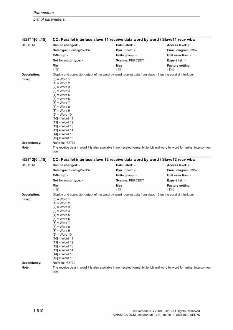
Parameters
List of parameters
1-610 © Siemens AG 2009 - 2013 All Rights ReservedSINAMICS DCM List Manual (LH8), 06/2013, 6RX1800-0ED76
Description: Display and connector output of the word-by-word receive data from slave 11 on the parallel interface.
Index: [0] = Word 1[1] = Word 2[2] = Word 3[3] = Word 4[4] = Word 5[5] = Word 6[6] = Word 7[7] = Word 8[8] = Word 9[9] = Word 10[10] = Word 11[11] = Word 12[12] = Word 13[13] = Word 14[14] = Word 15[15] = Word 16
Dependency: Refer to: r52731
Note: The receive data in word 1 is also available in non-scaled format bit by bit and word by word for further interconnec-tion.
Description: Display and connector output of the word-by-word receive data from slave 12 on the parallel interface.
Index: [0] = Word 1[1] = Word 2[2] = Word 3[3] = Word 4[4] = Word 5[5] = Word 6[6] = Word 7[7] = Word 8[8] = Word 9[9] = Word 10[10] = Word 11[11] = Word 12[12] = Word 13[13] = Word 14[14] = Word 15[15] = Word 16
Dependency: Refer to: r52732
Note: The receive data in word 1 is also available in non-scaled format bit by bit and word by word for further interconnec-tion.
r52711[0...15] CO: Parallel interface slave 11 receive data word by word / Slave11 recv wbwDC_CTRL Can be changed: - Calculated: - Access level: 2
Data type: FloatingPoint32 Dyn. index: - Func. diagram: 9352
P-Group: - Units group: - Unit selection: -
Not for motor type: - Scaling: PERCENT Expert list: 1
Min Max Factory setting - [%] - [%] - [%]
r52712[0...15] CO: Parallel interface slave 12 receive data word by word / Slave12 recv wbwDC_CTRL Can be changed: - Calculated: - Access level: 2
Data type: FloatingPoint32 Dyn. index: - Func. diagram: 9352
P-Group: - Units group: - Unit selection: -
Not for motor type: - Scaling: PERCENT Expert list: 1
Min Max Factory setting - [%] - [%] - [%]
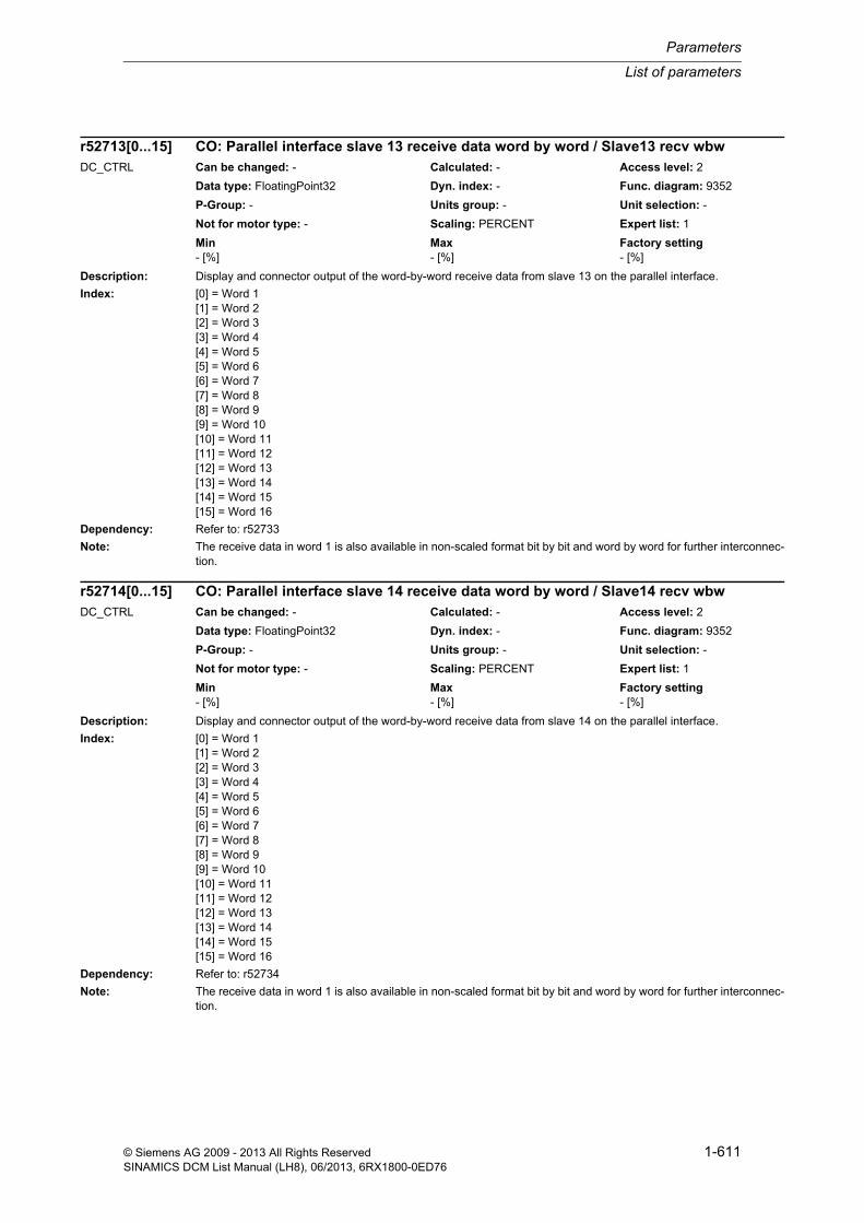
List of parameters
Parameters
1-611© Siemens AG 2009 - 2013 All Rights ReservedSINAMICS DCM List Manual (LH8), 06/2013, 6RX1800-0ED76
Description: Display and connector output of the word-by-word receive data from slave 13 on the parallel interface.
Index: [0] = Word 1[1] = Word 2[2] = Word 3[3] = Word 4[4] = Word 5[5] = Word 6[6] = Word 7[7] = Word 8[8] = Word 9[9] = Word 10[10] = Word 11[11] = Word 12[12] = Word 13[13] = Word 14[14] = Word 15[15] = Word 16
Dependency: Refer to: r52733
Note: The receive data in word 1 is also available in non-scaled format bit by bit and word by word for further interconnec-tion.
Description: Display and connector output of the word-by-word receive data from slave 14 on the parallel interface.
Index: [0] = Word 1[1] = Word 2[2] = Word 3[3] = Word 4[4] = Word 5[5] = Word 6[6] = Word 7[7] = Word 8[8] = Word 9[9] = Word 10[10] = Word 11[11] = Word 12[12] = Word 13[13] = Word 14[14] = Word 15[15] = Word 16
Dependency: Refer to: r52734
Note: The receive data in word 1 is also available in non-scaled format bit by bit and word by word for further interconnec-tion.
r52713[0...15] CO: Parallel interface slave 13 receive data word by word / Slave13 recv wbwDC_CTRL Can be changed: - Calculated: - Access level: 2
Data type: FloatingPoint32 Dyn. index: - Func. diagram: 9352
P-Group: - Units group: - Unit selection: -
Not for motor type: - Scaling: PERCENT Expert list: 1
Min Max Factory setting - [%] - [%] - [%]
r52714[0...15] CO: Parallel interface slave 14 receive data word by word / Slave14 recv wbwDC_CTRL Can be changed: - Calculated: - Access level: 2
Data type: FloatingPoint32 Dyn. index: - Func. diagram: 9352
P-Group: - Units group: - Unit selection: -
Not for motor type: - Scaling: PERCENT Expert list: 1
Min Max Factory setting - [%] - [%] - [%]

Parameters
List of parameters
1-612 © Siemens AG 2009 - 2013 All Rights ReservedSINAMICS DCM List Manual (LH8), 06/2013, 6RX1800-0ED76
Description: Display and connector output of the word-by-word receive data from slave 15 on the parallel interface.
Index: [0] = Word 1[1] = Word 2[2] = Word 3[3] = Word 4[4] = Word 5[5] = Word 6[6] = Word 7[7] = Word 8[8] = Word 9[9] = Word 10[10] = Word 11[11] = Word 12[12] = Word 13[13] = Word 14[14] = Word 15[15] = Word 16
Dependency: Refer to: r52735
Note: The receive data in word 1 is also available in non-scaled format bit by bit and word by word for further interconnec-tion.
Description: Display and connector output of the word-by-word receive data from slave 16 on the parallel interface.
Index: [0] = Word 1[1] = Word 2[2] = Word 3[3] = Word 4[4] = Word 5[5] = Word 6[6] = Word 7[7] = Word 8[8] = Word 9[9] = Word 10[10] = Word 11[11] = Word 12[12] = Word 13[13] = Word 14[14] = Word 15[15] = Word 16
Dependency: Refer to: r52736
Note: The receive data in word 1 is also available in non-scaled format bit by bit and word by word for further interconnec-tion.
r52715[0...15] CO: Parallel interface slave 15 receive data word by word / Slave15 recv wbwDC_CTRL Can be changed: - Calculated: - Access level: 2
Data type: FloatingPoint32 Dyn. index: - Func. diagram: 9352
P-Group: - Units group: - Unit selection: -
Not for motor type: - Scaling: PERCENT Expert list: 1
Min Max Factory setting - [%] - [%] - [%]
r52716[0...15] CO: Parallel interface slave 16 receive data word by word / Slave16 recv wbwDC_CTRL Can be changed: - Calculated: - Access level: 2
Data type: FloatingPoint32 Dyn. index: - Func. diagram: 9352
P-Group: - Units group: - Unit selection: -
Not for motor type: - Scaling: PERCENT Expert list: 1
Min Max Factory setting - [%] - [%] - [%]

List of parameters
Parameters
1-613© Siemens AG 2009 - 2013 All Rights ReservedSINAMICS DCM List Manual (LH8), 06/2013, 6RX1800-0ED76
Description: Display and binector/connector output for receive word 1 from the master on the parallel interface.
Dependency: Refer to: r52700
Note: Receive word 1 is also available scaled word by word for further interconnection.
Description: Display and binector/connector output for receive word 1 from slave 1 on the parallel interface.
Dependency: Refer to: r52701
Note: Receive word 1 is also available scaled word by word for further interconnection.
r52720.0...15 CO/BO: Parallel interface master receive word 1 bit by bit / Master recv1 bbbDC_CTRL Can be changed: - Calculated: - Access level: 2
Data type: Unsigned16 Dyn. index: - Func. diagram: 9352
P-Group: - Units group: - Unit selection: -
Not for motor type: - Scaling: - Expert list: 1
Min Max Factory setting - - -
Bit field: Bit Signal name 1 signal 0 signal FP00 Bit 0 Yes No 935201 Bit 1 Yes No 935202 Bit 2 Yes No 935203 Bit 3 Yes No 935204 Bit 4 Yes No 935205 Bit 5 Yes No 935206 Bit 6 Yes No 935207 Bit 7 Yes No 935208 Bit 8 Yes No 935209 Bit 9 Yes No 935210 Bit 10 Yes No 935211 Bit 11 Yes No 935212 Bit 12 Yes No 935213 Bit 13 Yes No 935214 Bit 14 Yes No 935215 Bit 15 Yes No 9352
r52721.0...15 CO/BO: Parallel interface slave 1 receive word 1 bit by bit / Slave1 recv1 bbbDC_CTRL Can be changed: - Calculated: - Access level: 2
Data type: Unsigned16 Dyn. index: - Func. diagram: 9352
P-Group: - Units group: - Unit selection: -
Not for motor type: - Scaling: - Expert list: 1
Min Max Factory setting - - -
Bit field: Bit Signal name 1 signal 0 signal FP00 Bit 0 Yes No 935201 Bit 1 Yes No 935202 Bit 2 Yes No 935203 Bit 3 Yes No 935204 Bit 4 Yes No 935205 Bit 5 Yes No 935206 Bit 6 Yes No 935207 Bit 7 Yes No 935208 Bit 8 Yes No 935209 Bit 9 Yes No 935210 Bit 10 Yes No 935211 Bit 11 Yes No 935212 Bit 12 Yes No 935213 Bit 13 Yes No 935214 Bit 14 Yes No 935215 Bit 15 Yes No 9352

Parameters
List of parameters
1-614 © Siemens AG 2009 - 2013 All Rights ReservedSINAMICS DCM List Manual (LH8), 06/2013, 6RX1800-0ED76
Description: Display and binector/connector output for receive word 1 from slave 2 on the parallel interface.
Dependency: Refer to: r52702
Note: Receive word 1 is also available scaled word by word for further interconnection.
Description: Display and binector/connector output for receive word 1 from slave 3 on the parallel interface.
Dependency: Refer to: r52703
Note: Receive word 1 is also available scaled word by word for further interconnection.
r52722.0...15 CO/BO: Parallel interface slave 2 receive word 1 bit by bit / Slave2 recv1 bbbDC_CTRL Can be changed: - Calculated: - Access level: 2
Data type: Unsigned16 Dyn. index: - Func. diagram: 9352
P-Group: - Units group: - Unit selection: -
Not for motor type: - Scaling: - Expert list: 1
Min Max Factory setting - - -
Bit field: Bit Signal name 1 signal 0 signal FP00 Bit 0 Yes No 935201 Bit 1 Yes No 935202 Bit 2 Yes No 935203 Bit 3 Yes No 935204 Bit 4 Yes No 935205 Bit 5 Yes No 935206 Bit 6 Yes No 935207 Bit 7 Yes No 935208 Bit 8 Yes No 935209 Bit 9 Yes No 935210 Bit 10 Yes No 935211 Bit 11 Yes No 935212 Bit 12 Yes No 935213 Bit 13 Yes No 935214 Bit 14 Yes No 935215 Bit 15 Yes No 9352
r52723.0...15 CO/BO: Parallel interface slave 3 receive word 1 bit by bit / Slave3 recv1 bbbDC_CTRL Can be changed: - Calculated: - Access level: 2
Data type: Unsigned16 Dyn. index: - Func. diagram: 9352
P-Group: - Units group: - Unit selection: -
Not for motor type: - Scaling: - Expert list: 1
Min Max Factory setting - - -
Bit field: Bit Signal name 1 signal 0 signal FP00 Bit 0 Yes No 935201 Bit 1 Yes No 935202 Bit 2 Yes No 935203 Bit 3 Yes No 935204 Bit 4 Yes No 935205 Bit 5 Yes No 935206 Bit 6 Yes No 935207 Bit 7 Yes No 935208 Bit 8 Yes No 935209 Bit 9 Yes No 935210 Bit 10 Yes No 935211 Bit 11 Yes No 935212 Bit 12 Yes No 935213 Bit 13 Yes No 935214 Bit 14 Yes No 935215 Bit 15 Yes No 9352

List of parameters
Parameters
1-615© Siemens AG 2009 - 2013 All Rights ReservedSINAMICS DCM List Manual (LH8), 06/2013, 6RX1800-0ED76
Description: Display and binector/connector output for receive word 1 from slave 4 on the parallel interface.
Dependency: Refer to: r52704
Note: Receive word 1 is also available scaled word by word for further interconnection.
Description: Display and binector/connector output for receive word 1 from slave 5 on the parallel interface.
Dependency: Refer to: r52705
Note: Receive word 1 is also available scaled word by word for further interconnection.
r52724.0...15 CO/BO: Parallel interface slave 4 receive word 1 bit by bit / Slave4 recv1 bbbDC_CTRL Can be changed: - Calculated: - Access level: 2
Data type: Unsigned16 Dyn. index: - Func. diagram: 9352
P-Group: - Units group: - Unit selection: -
Not for motor type: - Scaling: - Expert list: 1
Min Max Factory setting - - -
Bit field: Bit Signal name 1 signal 0 signal FP00 Bit 0 Yes No 935201 Bit 1 Yes No 935202 Bit 2 Yes No 935203 Bit 3 Yes No 935204 Bit 4 Yes No 935205 Bit 5 Yes No 935206 Bit 6 Yes No 935207 Bit 7 Yes No 935208 Bit 8 Yes No 935209 Bit 9 Yes No 935210 Bit 10 Yes No 935211 Bit 11 Yes No 935212 Bit 12 Yes No 935213 Bit 13 Yes No 935214 Bit 14 Yes No 935215 Bit 15 Yes No 9352
r52725.0...15 CO/BO: Parallel interface slave 5 receive word 1 bit by bit / Slave5 recv1 bbbDC_CTRL Can be changed: - Calculated: - Access level: 2
Data type: Unsigned16 Dyn. index: - Func. diagram: 9352
P-Group: - Units group: - Unit selection: -
Not for motor type: - Scaling: - Expert list: 1
Min Max Factory setting - - -
Bit field: Bit Signal name 1 signal 0 signal FP00 Bit 0 Yes No 935201 Bit 1 Yes No 935202 Bit 2 Yes No 935203 Bit 3 Yes No 935204 Bit 4 Yes No 935205 Bit 5 Yes No 935206 Bit 6 Yes No 935207 Bit 7 Yes No 935208 Bit 8 Yes No 935209 Bit 9 Yes No 935210 Bit 10 Yes No 935211 Bit 11 Yes No 935212 Bit 12 Yes No 935213 Bit 13 Yes No 935214 Bit 14 Yes No 935215 Bit 15 Yes No 9352

Parameters
List of parameters
1-616 © Siemens AG 2009 - 2013 All Rights ReservedSINAMICS DCM List Manual (LH8), 06/2013, 6RX1800-0ED76
Description: Display and binector/connector output for receive word 1 from slave 6 on the parallel interface.
Dependency: Refer to: r52706
Note: Receive word 1 is also available scaled word by word for further interconnection.
Description: Display and binector/connector output for receive word 1 from slave 7 on the parallel interface.
Dependency: Refer to: r52707
Note: Receive word 1 is also available scaled word by word for further interconnection.
r52726.0...15 CO/BO: Parallel interface slave 6 receive word 1 bit by bit / Slave6 recv1 bbbDC_CTRL Can be changed: - Calculated: - Access level: 2
Data type: Unsigned16 Dyn. index: - Func. diagram: 9352
P-Group: - Units group: - Unit selection: -
Not for motor type: - Scaling: - Expert list: 1
Min Max Factory setting - - -
Bit field: Bit Signal name 1 signal 0 signal FP00 Bit 0 Yes No 935201 Bit 1 Yes No 935202 Bit 2 Yes No 935203 Bit 3 Yes No 935204 Bit 4 Yes No 935205 Bit 5 Yes No 935206 Bit 6 Yes No 935207 Bit 7 Yes No 935208 Bit 8 Yes No 935209 Bit 9 Yes No 935210 Bit 10 Yes No 935211 Bit 11 Yes No 935212 Bit 12 Yes No 935213 Bit 13 Yes No 935214 Bit 14 Yes No 935215 Bit 15 Yes No 9352
r52727.0...15 CO/BO: Parallel interface slave 7 receive word 1 bit by bit / Slave7 recv1 bbbDC_CTRL Can be changed: - Calculated: - Access level: 2
Data type: Unsigned16 Dyn. index: - Func. diagram: 9352
P-Group: - Units group: - Unit selection: -
Not for motor type: - Scaling: - Expert list: 1
Min Max Factory setting - - -
Bit field: Bit Signal name 1 signal 0 signal FP00 Bit 0 Yes No 935201 Bit 1 Yes No 935202 Bit 2 Yes No 935203 Bit 3 Yes No 935204 Bit 4 Yes No 935205 Bit 5 Yes No 935206 Bit 6 Yes No 935207 Bit 7 Yes No 935208 Bit 8 Yes No 935209 Bit 9 Yes No 935210 Bit 10 Yes No 935211 Bit 11 Yes No 935212 Bit 12 Yes No 935213 Bit 13 Yes No 935214 Bit 14 Yes No 935215 Bit 15 Yes No 9352

List of parameters
Parameters
1-617© Siemens AG 2009 - 2013 All Rights ReservedSINAMICS DCM List Manual (LH8), 06/2013, 6RX1800-0ED76
Description: Display and binector/connector output for receive word 1 from slave 8 on the parallel interface.
Dependency: Refer to: r52708
Note: Receive word 1 is also available scaled word by word for further interconnection.
Description: Display and binector/connector output for receive word 1 from slave 9 on the parallel interface.
Dependency: Refer to: r52709
Note: Receive word 1 is also available scaled word by word for further interconnection.
r52728.0...15 CO/BO: Parallel interface slave 8 receive word 1 bit by bit / Slave8 recv1 bbbDC_CTRL Can be changed: - Calculated: - Access level: 2
Data type: Unsigned16 Dyn. index: - Func. diagram: 9352
P-Group: - Units group: - Unit selection: -
Not for motor type: - Scaling: - Expert list: 1
Min Max Factory setting - - -
Bit field: Bit Signal name 1 signal 0 signal FP00 Bit 0 Yes No 935201 Bit 1 Yes No 935202 Bit 2 Yes No 935203 Bit 3 Yes No 935204 Bit 4 Yes No 935205 Bit 5 Yes No 935206 Bit 6 Yes No 935207 Bit 7 Yes No 935208 Bit 8 Yes No 935209 Bit 9 Yes No 935210 Bit 10 Yes No 935211 Bit 11 Yes No 935212 Bit 12 Yes No 935213 Bit 13 Yes No 935214 Bit 14 Yes No 935215 Bit 15 Yes No 9352
r52729.0...15 CO/BO: Parallel interface slave 9 receive word 1 bit by bit / Slave9 recv1 bbbDC_CTRL Can be changed: - Calculated: - Access level: 2
Data type: Unsigned16 Dyn. index: - Func. diagram: 9352
P-Group: - Units group: - Unit selection: -
Not for motor type: - Scaling: - Expert list: 1
Min Max Factory setting - - -
Bit field: Bit Signal name 1 signal 0 signal FP00 Bit 0 Yes No 935201 Bit 1 Yes No 935202 Bit 2 Yes No 935203 Bit 3 Yes No 935204 Bit 4 Yes No 935205 Bit 5 Yes No 935206 Bit 6 Yes No 935207 Bit 7 Yes No 935208 Bit 8 Yes No 935209 Bit 9 Yes No 935210 Bit 10 Yes No 935211 Bit 11 Yes No 935212 Bit 12 Yes No 935213 Bit 13 Yes No 935214 Bit 14 Yes No 935215 Bit 15 Yes No 9352

Parameters
List of parameters
1-618 © Siemens AG 2009 - 2013 All Rights ReservedSINAMICS DCM List Manual (LH8), 06/2013, 6RX1800-0ED76
Description: Display and binector/connector output for receive word 1 from slave 10 on the parallel interface.
Dependency: Refer to: r52710
Note: Receive word 1 is also available scaled word by word for further interconnection.
Description: Display and binector/connector output for receive word 1 from slave 11 on the parallel interface.
Dependency: Refer to: r52711
Note: Receive word 1 is also available scaled word by word for further interconnection.
r52730.0...15 CO/BO: Parallel interface slave 10 receive word 1 bit by bit / Slave10 recv1 bbbDC_CTRL Can be changed: - Calculated: - Access level: 2
Data type: Unsigned16 Dyn. index: - Func. diagram: 9352
P-Group: - Units group: - Unit selection: -
Not for motor type: - Scaling: - Expert list: 1
Min Max Factory setting - - -
Bit field: Bit Signal name 1 signal 0 signal FP00 Bit 0 Yes No 935201 Bit 1 Yes No 935202 Bit 2 Yes No 935203 Bit 3 Yes No 935204 Bit 4 Yes No 935205 Bit 5 Yes No 935206 Bit 6 Yes No 935207 Bit 7 Yes No 935208 Bit 8 Yes No 935209 Bit 9 Yes No 935210 Bit 10 Yes No 935211 Bit 11 Yes No 935212 Bit 12 Yes No 935213 Bit 13 Yes No 935214 Bit 14 Yes No 935215 Bit 15 Yes No 9352
r52731.0...15 CO/BO: Parallel interface slave 11 receive word 1 bit by bit / Slave11 recv1 bbbDC_CTRL Can be changed: - Calculated: - Access level: 2
Data type: Unsigned16 Dyn. index: - Func. diagram: 9352
P-Group: - Units group: - Unit selection: -
Not for motor type: - Scaling: - Expert list: 1
Min Max Factory setting - - -
Bit field: Bit Signal name 1 signal 0 signal FP00 Bit 0 Yes No 935201 Bit 1 Yes No 935202 Bit 2 Yes No 935203 Bit 3 Yes No 935204 Bit 4 Yes No 935205 Bit 5 Yes No 935206 Bit 6 Yes No 935207 Bit 7 Yes No 935208 Bit 8 Yes No 935209 Bit 9 Yes No 935210 Bit 10 Yes No 935211 Bit 11 Yes No 935212 Bit 12 Yes No 935213 Bit 13 Yes No 935214 Bit 14 Yes No 935215 Bit 15 Yes No 9352
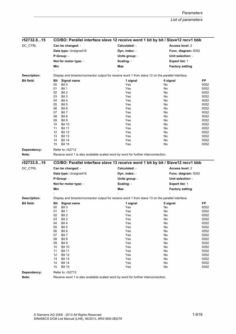
List of parameters
Parameters
1-619© Siemens AG 2009 - 2013 All Rights ReservedSINAMICS DCM List Manual (LH8), 06/2013, 6RX1800-0ED76
Description: Display and binector/connector output for receive word 1 from slave 12 on the parallel interface.
Dependency: Refer to: r52712
Note: Receive word 1 is also available scaled word by word for further interconnection.
Description: Display and binector/connector output for receive word 1 from slave 13 on the parallel interface.
Dependency: Refer to: r52713
Note: Receive word 1 is also available scaled word by word for further interconnection.
r52732.0...15 CO/BO: Parallel interface slave 12 receive word 1 bit by bit / Slave12 recv1 bbbDC_CTRL Can be changed: - Calculated: - Access level: 2
Data type: Unsigned16 Dyn. index: - Func. diagram: 9352
P-Group: - Units group: - Unit selection: -
Not for motor type: - Scaling: - Expert list: 1
Min Max Factory setting - - -
Bit field: Bit Signal name 1 signal 0 signal FP00 Bit 0 Yes No 935201 Bit 1 Yes No 935202 Bit 2 Yes No 935203 Bit 3 Yes No 935204 Bit 4 Yes No 935205 Bit 5 Yes No 935206 Bit 6 Yes No 935207 Bit 7 Yes No 935208 Bit 8 Yes No 935209 Bit 9 Yes No 935210 Bit 10 Yes No 935211 Bit 11 Yes No 935212 Bit 12 Yes No 935213 Bit 13 Yes No 935214 Bit 14 Yes No 935215 Bit 15 Yes No 9352
r52733.0...15 CO/BO: Parallel interface slave 13 receive word 1 bit by bit / Slave12 recv1 bbbDC_CTRL Can be changed: - Calculated: - Access level: 2
Data type: Unsigned16 Dyn. index: - Func. diagram: 9352
P-Group: - Units group: - Unit selection: -
Not for motor type: - Scaling: - Expert list: 1
Min Max Factory setting - - -
Bit field: Bit Signal name 1 signal 0 signal FP00 Bit 0 Yes No 935201 Bit 1 Yes No 935202 Bit 2 Yes No 935203 Bit 3 Yes No 935204 Bit 4 Yes No 935205 Bit 5 Yes No 935206 Bit 6 Yes No 935207 Bit 7 Yes No 935208 Bit 8 Yes No 935209 Bit 9 Yes No 935210 Bit 10 Yes No 935211 Bit 11 Yes No 935212 Bit 12 Yes No 935213 Bit 13 Yes No 935214 Bit 14 Yes No 935215 Bit 15 Yes No 9352

Parameters
List of parameters
1-620 © Siemens AG 2009 - 2013 All Rights ReservedSINAMICS DCM List Manual (LH8), 06/2013, 6RX1800-0ED76
Description: Display and binector/connector output for receive word 1 from slave 14 on the parallel interface.
Dependency: Refer to: r52714
Note: Receive word 1 is also available scaled word by word for further interconnection.
Description: Display and binector/connector output for receive word 1 from slave 15 on the parallel interface.
Dependency: Refer to: r52715
Note: Receive word 1 is also available scaled word by word for further interconnection.
r52734.0...15 CO/BO: Parallel interface slave 14 receive word 1 bit by bit / Slave14 recv1 bbbDC_CTRL Can be changed: - Calculated: - Access level: 2
Data type: Unsigned16 Dyn. index: - Func. diagram: 9352
P-Group: - Units group: - Unit selection: -
Not for motor type: - Scaling: - Expert list: 1
Min Max Factory setting - - -
Bit field: Bit Signal name 1 signal 0 signal FP00 Bit 0 Yes No 935201 Bit 1 Yes No 935202 Bit 2 Yes No 935203 Bit 3 Yes No 935204 Bit 4 Yes No 935205 Bit 5 Yes No 935206 Bit 6 Yes No 935207 Bit 7 Yes No 935208 Bit 8 Yes No 935209 Bit 9 Yes No 935210 Bit 10 Yes No 935211 Bit 11 Yes No 935212 Bit 12 Yes No 935213 Bit 13 Yes No 935214 Bit 14 Yes No 935215 Bit 15 Yes No 9352
r52735.0...15 CO/BO: Parallel interface slave 15 receive word 1 bit by bit / Slave15 recv1 bbbDC_CTRL Can be changed: - Calculated: - Access level: 2
Data type: Unsigned16 Dyn. index: - Func. diagram: 9352
P-Group: - Units group: - Unit selection: -
Not for motor type: - Scaling: - Expert list: 1
Min Max Factory setting - - -
Bit field: Bit Signal name 1 signal 0 signal FP00 Bit 0 Yes No 935201 Bit 1 Yes No 935202 Bit 2 Yes No 935203 Bit 3 Yes No 935204 Bit 4 Yes No 935205 Bit 5 Yes No 935206 Bit 6 Yes No 935207 Bit 7 Yes No 935208 Bit 8 Yes No 935209 Bit 9 Yes No 935210 Bit 10 Yes No 935211 Bit 11 Yes No 935212 Bit 12 Yes No 935213 Bit 13 Yes No 935214 Bit 14 Yes No 935215 Bit 15 Yes No 9352

List of parameters
Parameters
1-621© Siemens AG 2009 - 2013 All Rights ReservedSINAMICS DCM List Manual (LH8), 06/2013, 6RX1800-0ED76
Description: Display and binector/connector output for receive word 1 from slave 16 on the parallel interface.
Dependency: Refer to: r52716
Note: Receive word 1 is also available scaled word by word for further interconnection.
Description: Display and connector output for the sequence control operating state.
Note: The values correspond to the operating state of the drive (r0002 (DC_CTRL)).
Description: Display and connector output of output 0 during the optimization run.
r52736.0...15 CO/BO: Parallel interface slave 16 receive word 1 bit by bit / Slave16 recv1 bbbDC_CTRL Can be changed: - Calculated: - Access level: 2
Data type: Unsigned16 Dyn. index: - Func. diagram: 9352
P-Group: - Units group: - Unit selection: -
Not for motor type: - Scaling: - Expert list: 1
Min Max Factory setting - - -
Bit field: Bit Signal name 1 signal 0 signal FP00 Bit 0 Yes No 935201 Bit 1 Yes No 935202 Bit 2 Yes No 935203 Bit 3 Yes No 935204 Bit 4 Yes No 935205 Bit 5 Yes No 935206 Bit 6 Yes No 935207 Bit 7 Yes No 935208 Bit 8 Yes No 935209 Bit 9 Yes No 935210 Bit 10 Yes No 935211 Bit 11 Yes No 935212 Bit 12 Yes No 935213 Bit 13 Yes No 935214 Bit 14 Yes No 935215 Bit 15 Yes No 9352
r52800 CO: Sequence control operating state / S ctr op stateDC_CTRL Can be changed: - Calculated: - Access level: 2
Data type: Unsigned16 Dyn. index: - Func. diagram: 2651
P-Group: - Units group: - Unit selection: -
Not for motor type: - Scaling: - Expert list: 1
Min Max Factory setting - - -
r52900 CO: Optimization run output 0 / Opt run outp 0DC_CTRL Can be changed: - Calculated: - Access level: 2
Data type: FloatingPoint32 Dyn. index: - Func. diagram: 2660
P-Group: - Units group: - Unit selection: -
Not for motor type: - Scaling: PERCENT Expert list: 1
Min Max Factory setting - [%] - [%] - [%]

Parameters
List of parameters
1-622 © Siemens AG 2009 - 2013 All Rights ReservedSINAMICS DCM List Manual (LH8), 06/2013, 6RX1800-0ED76
Description: Display and connector output of output 1 during the optimization run.
Description: Display and connector output of output 2 during the optimization run.
Description: Display and connector output of output 3 during the optimization run.
Description: Display and connector output of output 4 during the optimization run.
Description: Display and connector output for the raw values from the measurements of Power Stack ASIC 1.
For devices with 480 V:
- 0 corresponds to -825.0 V
- 32767 corresponds to 0 V
- 65535 corresponds to +825.0 V
r52901 CO: Optimization run output 1 / Opt run outp 1DC_CTRL Can be changed: - Calculated: - Access level: 2
Data type: FloatingPoint32 Dyn. index: - Func. diagram: 2660
P-Group: - Units group: - Unit selection: -
Not for motor type: - Scaling: PERCENT Expert list: 1
Min Max Factory setting - [%] - [%] - [%]
r52902 CO: Optimization run output 2 / Opt run outp 2DC_CTRL Can be changed: - Calculated: - Access level: 2
Data type: FloatingPoint32 Dyn. index: - Func. diagram: 2660
P-Group: - Units group: - Unit selection: -
Not for motor type: - Scaling: PERCENT Expert list: 1
Min Max Factory setting - [%] - [%] - [%]
r52903 CO: Optimization run output 3 / Opt run outp 3DC_CTRL Can be changed: - Calculated: - Access level: 2
Data type: FloatingPoint32 Dyn. index: - Func. diagram: 2660
P-Group: - Units group: - Unit selection: -
Not for motor type: - Scaling: PERCENT Expert list: 1
Min Max Factory setting - [%] - [%] - [%]
r52904 CO: Optimization run output 4 / Opt run outp 4DC_CTRL Can be changed: - Calculated: - Access level: 2
Data type: FloatingPoint32 Dyn. index: - Func. diagram: 2660
P-Group: - Units group: - Unit selection: -
Not for motor type: - Scaling: PERCENT Expert list: 1
Min Max Factory setting - [%] - [%] - [%]
r52921[0...4] CO: Measurement results ASIC 1 raw values / Meas res ASIC1 rawDC_CTRL Can be changed: - Calculated: - Access level: 4
Data type: Unsigned16 Dyn. index: - Func. diagram: 8054
P-Group: - Units group: - Unit selection: -
Not for motor type: - Scaling: - Expert list: 1
Min Max Factory setting - - -

List of parameters
Parameters
1-623© Siemens AG 2009 - 2013 All Rights ReservedSINAMICS DCM List Manual (LH8), 06/2013, 6RX1800-0ED76
For devices with 575 V:
- 0 corresponds to -1036.2 V
- 32767 corresponds to 0 V
- 65535 corresponds to +1036.2 V
For devices with 1000 V:
- 0 corresponds to -1795.2 V
- 32767 corresponds to 0 V
- 65535 corresponds to +1795.2 V
Index: [0] = Phase VU[1] = Phase VW[2] = Voltage CV[3] = Voltage CD[4] = Voltage S13V
Dependency: Refer to: r52922, r52923
Note: This parameter is used solely for internal diagnostics.
Description: Display and connector output for the raw values from the measurements of Power Stack ASIC 2.
For voltage channels:
- 0 corresponds to -825.0 V
- 32767 corresponds to 0 V
- 65535 corresponds to +825.0 V
For the current channel:
- 49151 corresponds to 0 A
For devices with rated field current = 3A:
- 8218 corresponds to 3 A
For devices with rated field current = 5 A:
- 9065 corresponds to 5 A
For devices with rated field current = 10 A:
- 9065 corresponds to 10 A
For devices with rated field current = 15 A:
- 29108 corresponds to 15 A
For devices with rated field current = 25 A:
- 15746 corresponds to 25 A
For devices with rated field current = 30 A & A7115:
- 9065 corresponds to 30 A
For devices with rated field current = 30 A & A7116:
- 24608 corresponds to 30 A
For devices with rated field current = 40 A:
- 16427 corresponds to 40 A
For devices with rated field current = 85 A:
- 14382 corresponds to 85 A
Index: [0] = Raw value voltage 3U3W[1] = Raw value voltage 3C3D[2] = Raw value field current
Dependency: Refer to: r52921, r52923
Note: This parameter is used solely for internal diagnostics.
r52922[0...2] CO: Measurement results ASIC 2 raw values / Meas res ASIC2 rawDC_CTRL Can be changed: - Calculated: - Access level: 4
Data type: Unsigned16 Dyn. index: - Func. diagram: 8054
P-Group: - Units group: - Unit selection: -
Not for motor type: - Scaling: - Expert list: 1
Min Max Factory setting - - -

Parameters
List of parameters
1-624 © Siemens AG 2009 - 2013 All Rights ReservedSINAMICS DCM List Manual (LH8), 06/2013, 6RX1800-0ED76
Description: Display and connector output for raw values when measuring current actual values.
The following applies:
- 0 corresponds to approx. 3 x device rated current in negative direction
- 32767 corresponds to 0 A
- 65535 corresponds to approx. 3 x device rated current in positive direction
Index: [0] = Armature current 1[1] = Armature current 2
Dependency: Refer to: r52921, r52922
Note: This parameter is used solely for internal diagnostics.
Description: Display and connector output for the scan values of line voltages UV, WV, WU.
Index: [0] = Line voltage UV[1] = Line voltage VW[2] = Line voltage WU[3] = Field line voltage
Description: Display and connector output for the armature voltage/field voltage scan values.
Index: [0] = Scan values of Ua[1] = Scan values of Uf
Description: Display and connector output for the armature current and field current scan values.
r52923[0...1] CO: Measurement results current actual values raw values / Meas res I_act rawDC_CTRL Can be changed: - Calculated: - Access level: 4
Data type: Unsigned16 Dyn. index: - Func. diagram: 8054
P-Group: - Units group: - Unit selection: -
Not for motor type: - Scaling: - Expert list: 1
Min Max Factory setting - - -
r52950[0...3] CO: Line voltages scan values / V_line sc valuesDC_CTRL Can be changed: - Calculated: - Access level: 3
Data type: FloatingPoint32 Dyn. index: - Func. diagram: 6950, 6952
P-Group: - Units group: - Unit selection: -
Not for motor type: - Scaling: - Expert list: 1
Min Max Factory setting - [V] - [V] - [V]
r52951[0...1] CO: Armature voltage/field voltage scan values / Ua/Uf scan_valuesDC_CTRL Can be changed: - Calculated: - Access level: 3
Data type: FloatingPoint32 Dyn. index: - Func. diagram: 6902, 6950, 6952
P-Group: - Units group: - Unit selection: -
Not for motor type: - Scaling: - Expert list: 1
Min Max Factory setting - [V] - [V] - [V]
r52952[0...3] CO: Armature current/field current scan values / Ia/If sc_valuesDC_CTRL Can be changed: - Calculated: - Access level: 3
Data type: FloatingPoint32 Dyn. index: - Func. diagram: 6850, 6851, 6912
P-Group: - Units group: - Unit selection: -
Not for motor type: - Scaling: - Expert list: 1
Min Max Factory setting - [A] - [A] - [A]

List of parameters
Parameters
1-625© Siemens AG 2009 - 2013 All Rights ReservedSINAMICS DCM List Manual (LH8), 06/2013, 6RX1800-0ED76
Index: [0] = Armature current Ia[1] = Field current If[2] = Armature current Ia current transformer I[3] = Armature current Ia current transformer II
Description: Display and connector output for the scan values of the thyristor blocking voltages.
Index: [0] = Blocking voltage thyristor X11[1] = Blocking voltage thyristor X12[2] = Blocking voltage thyristor X13[3] = Blocking voltage thyristor X14[4] = Blocking voltage thyristor X15[5] = Blocking voltage thyristor X16[6] = Blocking voltage thyristor X21[7] = Blocking voltage thyristor X22[8] = Blocking voltage thyristor X23[9] = Blocking voltage thyristor X24[10] = Blocking voltage thyristor X25[11] = Blocking voltage thyristor X26
Description: Displays the deviation of the last point in time on the averaged time grid from the last point in time on an original time grid (armature).
Description: Displays the deviation of the last point in time on the averaged time grid from the last point in time on an original time grid (field).
Description: Displays the DC offset (= direct-current component) of the armature line phases in volts.
Index: [0] = Armature phase UV[1] = Armature phase VW
r52953[0...11] CO: Thyristor blocking voltages scan values / V_thyr scan_valuesDC_CTRL Can be changed: - Calculated: - Access level: 3
Data type: FloatingPoint32 Dyn. index: - Func. diagram: 6950
P-Group: - Units group: - Unit selection: -
Not for motor type: - Scaling: - Expert list: 1
Min Max Factory setting - [V] - [V] - [V]
r52960 Armature line zero crossings deviation / Arm line zero devDC_CTRL Can be changed: - Calculated: - Access level: 4
Data type: FloatingPoint32 Dyn. index: - Func. diagram: 6950
P-Group: - Units group: - Unit selection: -
Not for motor type: - Scaling: - Expert list: 1
Min Max Factory setting - [µs] - [µs] - [µs]
r52961 Field line zero crossings deviation / Field line zero dvDC_CTRL Can be changed: - Calculated: - Access level: 4
Data type: FloatingPoint32 Dyn. index: - Func. diagram: 6952
P-Group: - Units group: - Unit selection: -
Not for motor type: - Scaling: - Expert list: 1
Min Max Factory setting - [µs] - [µs] - [µs]
r52965[0...1] Line analysis armature line phase offset / Arm line ph offsDC_CTRL Can be changed: - Calculated: - Access level: 4
Data type: FloatingPoint32 Dyn. index: - Func. diagram: 6950
P-Group: - Units group: - Unit selection: -
Not for motor type: - Scaling: - Expert list: 1
Min Max Factory setting - [V] - [V] - [V]

Parameters
List of parameters
1-626 © Siemens AG 2009 - 2013 All Rights ReservedSINAMICS DCM List Manual (LH8), 06/2013, 6RX1800-0ED76
Description: Displays the DC offset (= direct-current component) of the field line phases in volts.
Description: Displays the point in time (timer value) of the last positive zero crossing of armature phase UV.
Note: The value is displayed in [10 ns] unit.
Description: Displays the point in time (timer value) of the last negative zero crossing of armature phase UV.
Note: The value is displayed in [10 ns] unit.
Description: Displays the point in time (timer value) of the last positive zero crossing of armature phase VW.
Note: The value is displayed in [10 ns] unit.
Description: Displays the point in time (timer value) of the last negative zero crossing of armature phase UV.
Note: The value is displayed in [10 ns] unit.
r52966 Line analysis field line phase offset / Field line ph offsDC_CTRL Can be changed: - Calculated: - Access level: 4
Data type: FloatingPoint32 Dyn. index: - Func. diagram: 6952
P-Group: - Units group: - Unit selection: -
Not for motor type: - Scaling: - Expert list: 1
Min Max Factory setting - [V] - [V] - [V]
r52970 CO: Line analysis armature line zero crossing positive phase UV / Arm zero pos UVDC_CTRL Can be changed: - Calculated: - Access level: 4
Data type: Unsigned32 Dyn. index: - Func. diagram: 6950
P-Group: - Units group: - Unit selection: -
Not for motor type: - Scaling: - Expert list: 1
Min Max Factory setting - - -
r52971 CO: Line analysis armature line zero crossing negative phase UV / Arm zero neg UVDC_CTRL Can be changed: - Calculated: - Access level: 4
Data type: Unsigned32 Dyn. index: - Func. diagram: 6950
P-Group: - Units group: - Unit selection: -
Not for motor type: - Scaling: - Expert list: 1
Min Max Factory setting - - -
r52972 CO: Line analysis armature line zero crossing positive phase VW / Arm zero pos VWDC_CTRL Can be changed: - Calculated: - Access level: 4
Data type: Unsigned32 Dyn. index: - Func. diagram: 6950
P-Group: - Units group: - Unit selection: -
Not for motor type: - Scaling: - Expert list: 1
Min Max Factory setting - - -
r52973 CO: Line analysis armature line zero crossing negative phase VW / Arm zero neg VWDC_CTRL Can be changed: - Calculated: - Access level: 4
Data type: Unsigned32 Dyn. index: - Func. diagram: 6950
P-Group: - Units group: - Unit selection: -
Not for motor type: - Scaling: - Expert list: 1
Min Max Factory setting - - -

List of parameters
Parameters
1-627© Siemens AG 2009 - 2013 All Rights ReservedSINAMICS DCM List Manual (LH8), 06/2013, 6RX1800-0ED76
Description: Displays the point in time (timer value) of the last positive zero crossing of armature phase WU.
Note: The value is displayed in [10 ns] unit.
Description: Displays the point in time (timer value) of the last negative zero crossing of armature phase WU.
Note: The value is displayed in [10 ns] unit.
Description: Displays the point in time (timer value) of the last positive zero crossing of the field phase.
Note: The value is displayed in [10 ns] unit.
Description: Displays the point in time (timer value) of the last negative zero crossing of the field phase.
Note: The value is displayed in [10 ns] unit.
Description: Displays the cause of the armature firing pulse.
1: firing angle = firing angle specified by the armature current control (after Alpha G/W limiting).
2: firing angle = Alpha-W (= p50151, as Ia <> 0 or Ia = 0 for less than 125 µs).
3: firing angle = Alpha-W (= 165 °, as Ia = 0 for more than 125 µs).
r52974 CO: Line analysis armature line zero crossing positive phase WU / Arm zero pos WUDC_CTRL Can be changed: - Calculated: - Access level: 4
Data type: Unsigned32 Dyn. index: - Func. diagram: 6950
P-Group: - Units group: - Unit selection: -
Not for motor type: - Scaling: - Expert list: 1
Min Max Factory setting - - -
r52975 CO: Line analysis armature line zero crossing negative phase WU / Arm zero neg WUDC_CTRL Can be changed: - Calculated: - Access level: 4
Data type: Unsigned32 Dyn. index: - Func. diagram: 6950
P-Group: - Units group: - Unit selection: -
Not for motor type: - Scaling: - Expert list: 1
Min Max Factory setting - - -
r52976 CO: Line analysis field line zero crossing positive phase F / Field zero pos FDC_CTRL Can be changed: - Calculated: - Access level: 4
Data type: Unsigned32 Dyn. index: - Func. diagram: 6952
P-Group: - Units group: - Unit selection: -
Not for motor type: - Scaling: - Expert list: 1
Min Max Factory setting - - -
r52977 CO: Line analysis field line zero crossing negative phase F / Field zero neg FDC_CTRL Can be changed: - Calculated: - Access level: 4
Data type: Unsigned32 Dyn. index: - Func. diagram: 6952
P-Group: - Units group: - Unit selection: -
Not for motor type: - Scaling: - Expert list: 1
Min Max Factory setting - - -
r52980 Cause of the armature firing pulse / Cause arm fir plusDC_CTRL Can be changed: - Calculated: - Access level: 4
Data type: Unsigned8 Dyn. index: - Func. diagram: 8054
P-Group: - Units group: - Unit selection: -
Not for motor type: - Scaling: - Expert list: 1
Min Max Factory setting - - -

Parameters
List of parameters
1-628 © Siemens AG 2009 - 2013 All Rights ReservedSINAMICS DCM List Manual (LH8), 06/2013, 6RX1800-0ED76
4: The firing angle received from the parallel switching master was issued.
5: The firing angle received from the parallel switching master was no longer able to be realized, as this point in time has already been passed.
6: For a 12-pulse series circuit, a firing pulse delayed by 30 ° was output.
7:The firing angle specified by the thyristor check function was realized.
8:The master firing angle specified by the sequential phase control was realized.
9:The slave firing angle specified by the sequential phase control was realized.
1x:
firing angle = next possible point in time: firing angle update was not able to be realized.
2x:
firing angle = next possible point in time: new firing angle was not able to be realized.
3x:
firing angle = next possible point in time: calculated firing angle was not able to be realized.
Note: This parameter is only for internal SIEMENS troubleshooting.
Description: Displays the cause of the torque direction.
0: M0 no torque direction, as not in the operating mode.
1: M0 no torque direction as a firing angle > 165 ° was specified.
2: M0 no torque direction as the wait time according to p50160 is running.
3: M0 no torque direction as the signal selected with p50165 does not permit the required torque direction.
4: M0 no torque direction as the I=0 signal was 125 µs long but however was present for less than 625 µs. The torque-free interval is extended.
5: M0 no torque direction as the thyristor blocking voltage monitoring signals "thyristor conductive". The torque-free interval is extended.
6: M0 no torque direction as the immediate pulse inhibit according to p50177 has been selected.
7: M0 no torque direction, as an emergency stop is present.
8: M0 no torque direction, as the line supply is not OK.
9: M0 no torque direction, as a valid firing instant was not found (for example, this can occur in the slave connected in parallel if the master is lost).
10, 11, 12:
M0, MI, MII torque direction = r52106.
15: M0 no torque direction as the selected thyristor pair is inhibited during the thyristor check.
16: M0 no torque direction, as the slave connected in parallel is not in the operating state.
17: M0 no torque direction, as an immediate pulse inhibit was executed, because either an emergency stop is pres-ent or the CCP was triggered.
21, 22:
MI, MII Alpha-W pulse with second pulse in the old torque direction.
Cause: Ia was still not 625 µs long = 0.
23, 24:
MI, MII Alpha-W pulse with second pulse in the old torque direction.
Cause: thyristor blocking voltage monitoring signals "Thyristor conductive"
31, 32:
MI, MII Alpha-W pulse without second pulse in the old torque direction.
Cause: Ia was still not 625 µs long = 0.
33, 34:
MI, MII Alpha-W pulse without second pulse in the old torque direction.
Cause: thyristor blocking voltage monitoring signals "Thyristor conductive"
r52981 Cause of the torque direction / Cause M_dirDC_CTRL Can be changed: - Calculated: - Access level: 4
Data type: Unsigned8 Dyn. index: - Func. diagram: 8054
P-Group: - Units group: - Unit selection: -
Not for motor type: - Scaling: - Expert list: 1
Min Max Factory setting - - -

List of parameters
Parameters
1-629© Siemens AG 2009 - 2013 All Rights ReservedSINAMICS DCM List Manual (LH8), 06/2013, 6RX1800-0ED76
41, 42:
MI, MII Alpha-W pulse with second pulse in the old torque direction.
Cause: additional Alpha-W pulses according to p50179.
51, 52:
MI, MII Alpha-W pulse without second pulse in the old torque direction.
Cause: additional Alpha-W pulses according to p50161.
60, 61, 62:
M0, MI, MII torque direction according to p51840 (simulation operation).
71: MI the command "simultaneously fire all thyristors" (according to p50176) was performed.
81: MI the torque direction specified by the thyristor check was realized.
82: MII the torque direction specified by the thyristor check was realized.
95, 96, 97:
M0, MI, MII the torque direction of the parallel switching master was realized.
Note: This parameter is only for internal SIEMENS troubleshooting.
Description: Displays the number of zero current signals of the armature current.
For scan values below the threshold I = 0, the counter is incremented.
The counter is reset in the following cases:
- firing pulse.
- scan value above the threshold for I = 0.
Note: This parameter is only for internal SIEMENS troubleshooting.
The scan values are every 62.5 µs.
The threshold for I = 0 is 1 % of the rated unit current.
Description: Displays the thyristor code.
Bit 0 = 1: Thyristor 1 was fired
...
Bit 5 = 1: Thyristor 6 was fired
Bit 6 = 1: thyristors were fired for torque direction 1
Bit 7 = 1: thyristors were fired for torque direction 2
Note: This parameter is only for internal SIEMENS troubleshooting.
r52982 Armature current zero current signal / Ia I=0 signalDC_CTRL Can be changed: - Calculated: - Access level: 4
Data type: Unsigned8 Dyn. index: - Func. diagram: 8054
P-Group: - Units group: - Unit selection: -
Not for motor type: - Scaling: - Expert list: 1
Min Max Factory setting - - -
r52983 Thyristor code / Thyr_codeDC_CTRL Can be changed: - Calculated: - Access level: 4
Data type: Unsigned8 Dyn. index: - Func. diagram: 8054
P-Group: - Units group: - Unit selection: -
Not for motor type: - Scaling: - Expert list: 1
Min Max Factory setting - - -

Parameters
List of parameters
1-630 © Siemens AG 2009 - 2013 All Rights ReservedSINAMICS DCM List Manual (LH8), 06/2013, 6RX1800-0ED76
Description: Display and connector output for the CUD's digital inputs.
Dependency: For bits 08 to 15:
The terminal must be set as an input (p50789[0 to 3] = 0).
Note: DI: Digital Input
DI/DO: Bidirectional Digital Input/Output
Description: Display and connector output for the CUD's digital outputs.
Dependency: For bits 04 to 07:
The terminal must be set as an output (p50789[0...3] = 1).
Note: DO: Digital Output
DI/DO: Bidirectional Digital Input/Output
r53010.0...15 CO/BO: CUD digital inputs, status / CUD DI statusDC_CTRL Can be changed: - Calculated: - Access level: 2
Data type: Unsigned16 Dyn. index: - Func. diagram: 2050, 2060, 2065, 2580
P-Group: - Units group: - Unit selection: -
Not for motor type: - Scaling: - Expert list: 1
Min Max Factory setting - - -
Bit field: Bit Signal name 1 signal 0 signal FP00 DI 0 (X177.11) High Low 205001 DI 0 inverted (X177.11) High Low 205002 DI 1 (X177.12) High Low 205003 DI 1 inverted (X177.12) High Low 205004 DI 2 (X177.13) High Low 205005 DI 2 inverted (X177.13) High Low 205006 DI 3 (X177.14) High Low 205007 DI 3 inverted (X177.14) High Low 205008 DI/DO 4 (X177.15) High Low 206009 DI/DO 4 inverted (X177.15) High Low 206010 DI/DO 5 (X177.16) High Low 206011 DI/DO 5 inverted (X177.16) High Low 206012 DI/DO 6 (X177.17) High Low 206513 DI/DO 6 inverted (X177.17) High Low 206514 DI/DO 7 (X177.18) High Low 206515 DI/DO 7 inverted (X177.18) High Low 2065
r53020.0...7 CO/BO: CUD digital outputs status / CUD DO statusDC_CTRL Can be changed: - Calculated: - Access level: 2
Data type: Unsigned16 Dyn. index: - Func. diagram: 2055, 2060, 2065
P-Group: - Units group: - Unit selection: -
Not for motor type: - Scaling: - Expert list: 1
Min Max Factory setting - - -
Bit field: Bit Signal name 1 signal 0 signal FP00 DO 0 (X177.19) High Low 205501 DO 1 (X177.20) High Low 205502 DO 2 (X177.21) High Low 205503 DO 3 (X177.22) High Low 205504 DI/DO 4 (X177.15) High Low 206005 DI/DO 5 (X177.16) High Low 206006 DI/DO 6 (X177.17) High Low 206507 DI/DO 7 (X177.18) High Low 2065

List of parameters
Parameters
1-631© Siemens AG 2009 - 2013 All Rights ReservedSINAMICS DCM List Manual (LH8), 06/2013, 6RX1800-0ED76
Description: Display and connector output for the overload monitoring of the digital outputs.
Dependency: For bits 04 to 07:
The terminal must be set as an output (p50789[0...3] = 1).
Note: DO: Digital Output
DI/DO: Bidirectional Digital Input/Output
Description: Displays the state of the messages for speed comparisons and limits.
r53021.0...7 CO/BO: CUD digital outputs overload monitoring / CUD DO overloadDC_CTRL Can be changed: - Calculated: - Access level: 2
Data type: Unsigned16 Dyn. index: - Func. diagram: 2055, 2060, 2065
P-Group: - Units group: - Unit selection: -
Not for motor type: - Scaling: - Expert list: 1
Min Max Factory setting - - -
Bit field: Bit Signal name 1 signal 0 signal FP00 DO 0 (X177.19) overload present Yes No 205501 DO 1 (X177.20) overload present Yes No 205502 DO 2 (X177.21) overload present Yes No 205503 DO 3 (X177.22) overload present Yes No 205504 DI/DO 4 (X177.15) overload present Yes No 206005 DI/DO 5 (X177.16) overload present Yes No 206006 DI/DO 6 (X177.17) overload present Yes No 206507 DI/DO 7 (X177.18) overload present Yes No 2065
r53025.0...13 CO/BO: Speed messages / n messagesDC_CTRL Can be changed: - Calculated: - Access level: 2
Data type: Unsigned16 Dyn. index: - Func. diagram: 8020, 8025
P-Group: - Units group: - Unit selection: -
Not for motor type: - Scaling: - Expert list: 1
Min Max Factory setting - - -
Bit field: Bit Signal name 1 signal 0 signal FP00 Setpoint/actual value deviation 1 less than
thresholdYes No 8020
01 Setpoint/actual value deviation 1 less than threshold inverted
Yes No 8020
02 Setpoint/actual value deviation 2 less than threshold
Yes No 8020
03 Setpoint/actual value deviation 2 less than threshold inverted
Yes No 8020
04 Comparison setpoint reached Yes No 802005 Comparison setpoint reached inverted Yes No 802006 Deceleration speed reached Yes No 802007 Deceleration speed reached inverted Yes No 802008 Positive speed setpoint Yes No 802509 Positive speed setpoint inverted Yes No 802510 Overspeed Yes No 802511 Overspeed inverted Yes No 802512 Positive speed actual value Yes No 802513 Positive speed actual value inverted Yes No 8025

Parameters
List of parameters
1-632 © Siemens AG 2009 - 2013 All Rights ReservedSINAMICS DCM List Manual (LH8), 06/2013, 6RX1800-0ED76
Description: Control word for field current thresholds.
Description: Display and connector output for the "Wire break" message in the case of the CUD analog inputs.
Description: Display and connector output for the line contactor control.
Description: Displays the status of the line contactor control.
Dependency: Refer to: p51619
r53026.0...1 CO/BO: Field current messages / If messagesDC_CTRL Can be changed: - Calculated: - Access level: 2
Data type: Unsigned16 Dyn. index: - Func. diagram: 8025
P-Group: - Units group: - Unit selection: -
Not for motor type: - Scaling: - Expert list: 1
Min Max Factory setting - - -
Bit field: Bit Signal name 1 signal 0 signal FP00 Field current less than minimum field cur-
rent thresholdYes No -
01 Field current actual value less than field cur-rent setpoint x
Yes No -
r53030.0...1 CO/BO: CUD analog inputs wire break message / CUD AI wire brkDC_CTRL Can be changed: - Calculated: - Access level: 2
Data type: Unsigned16 Dyn. index: - Func. diagram: 2075, 2080
P-Group: - Units group: - Unit selection: -
Not for motor type: - Scaling: - Expert list: 1
Min Max Factory setting - - -
Bit field: Bit Signal name 1 signal 0 signal FP00 AI "Main setpoint" wire-break monitoring
respondedYes No 2075
01 AI 1 (X177.27/28) Wire-break monitoring responded
Yes No 2080
r53081.0...1 CO/BO: Sequence control line contactor control / Ctrl line contDC_CTRL Can be changed: - Calculated: - Access level: 2
Data type: Unsigned16 Dyn. index: - Func. diagram: 2651
P-Group: - Units group: - Unit selection: -
Not for motor type: - Scaling: - Expert list: 1
Min Max Factory setting - - -
Bit field: Bit Signal name 1 signal 0 signal FP00 Line contactor ON OFF 265101 Line contactor inverted ON OFF 2651
r53082.0 CO/BO: Line contactor state / Line cont stateDC_CTRL Can be changed: - Calculated: - Access level: 2
Data type: Unsigned16 Dyn. index: - Func. diagram: 2070
P-Group: - Units group: - Unit selection: -
Not for motor type: - Scaling: - Expert list: 1
Min Max Factory setting - - -
Bit field: Bit Signal name 1 signal 0 signal FP00 Line contactor ON Yes No 2070

List of parameters
Parameters
1-633© Siemens AG 2009 - 2013 All Rights ReservedSINAMICS DCM List Manual (LH8), 06/2013, 6RX1800-0ED76
Note: Re bit 00:
1 signal: The relay output for the line contactor is activated via binector input p51619.
0 signal: The relay output for the line contactor is de-activated via binector input p51619.
Description: Display and connector output for the status in the event of an E stop (emergency stop).
Description: Displays the state of the motor interface.
Dependency: Refer to: p50486, p50487, p50488, p50489
Description: Displays the state of temperature monitoring on the motor interface.
Dependency: Refer to: p50490, p50491, p50492
Description: Display and connector output/binector output for the state of the device fan.
r53100.0...1 CO/BO: E stop status / E stop statDC_CTRL Can be changed: - Calculated: - Access level: 2
Data type: Unsigned16 Dyn. index: - Func. diagram: 2070, 2580
P-Group: - Units group: - Unit selection: -
Not for motor type: - Scaling: - Expert list: 1
Min Max Factory setting - - -
Bit field: Bit Signal name 1 signal 0 signal FP00 No E stop Yes No 2070,
258001 E stop active Yes No 2070
r53120.0...3 CO/BO: Motor control checks / Mot mon stateDC_CTRL Can be changed: - Calculated: - Access level: 2
Data type: Unsigned16 Dyn. index: - Func. diagram: 8035
P-Group: - Units group: - Unit selection: -
Not for motor type: - Scaling: - Expert list: 1
Min Max Factory setting - - -
Bit field: Bit Signal name 1 signal 0 signal FP00 Brush length too short Yes (fault) No -01 Poor bearing condition Yes (fault) No -02 Motor fan fault Yes (fault) No -03 Motor temperature too high Yes (fault) No -
r53130.0...1 CO/BO: Motor interface temperature monitoring state / Mot temp_monDC_CTRL Can be changed: - Calculated: - Access level: 2
Data type: Unsigned16 Dyn. index: - Func. diagram: 8030
P-Group: - Units group: - Unit selection: -
Not for motor type: - Scaling: - Expert list: 1
Min Max Factory setting - - -
Bit field: Bit Signal name 1 signal 0 signal FP00 Motor temperature alarm Yes No -01 Motor temperature fault Yes No -
r53135.0...12 CO/BO: Device fan state / Dev fan stateDC_CTRL Can be changed: - Calculated: - Access level: 2
Data type: Unsigned16 Dyn. index: - Func. diagram: -
P-Group: - Units group: - Unit selection: -
Not for motor type: - Scaling: - Expert list: 1
Min Max Factory setting - - -

Parameters
List of parameters
1-634 © Siemens AG 2009 - 2013 All Rights ReservedSINAMICS DCM List Manual (LH8), 06/2013, 6RX1800-0ED76
Dependency: Refer to: p50082, p50096
Note: Dependent upon the order number (MLFB), the fan configuration may be as follows:
- No fans
- 2 DC fans
- 1 AC fan
Re bits 8 ... 11:
These bits are not effective on the Control Module.
Re bit 12:
This bit is only effective on the Control Module.
Description: Displays the integrated device fan.
Note: For the Control Module, fan "available" is always displayed as the Control Module only has one output to control the fan.
The display is independent of the state of the fan and only indicates the desired state.
Description: Display and connector output of the state of the fan and external fault for the Control Module.
Dependency: Refer to: p51832, p51833, p51834, p51835
Bit field: Bit Signal name 1 signal 0 signal FP00 Switch on fan ON OFF 804701 Switch on fan inverted ON OFF 804708 Fan 1 speed OK Yes No (too low) 804709 Fan 2 speed OK Yes No (too low) 804710 Fan 3 speed OK Yes No (too low) 804711 Fan 4 speed OK Yes No (too low) 804712 Control Module fan speed OK Yes No 8049
r53136 Device fan present / Device_fan presDC_CTRL Can be changed: - Calculated: - Access level: 2
Data type: Unsigned16 Dyn. index: - Func. diagram: 6960
P-Group: - Units group: - Unit selection: -
Not for motor type: - Scaling: - Expert list: 1
Min Max Factory setting - - -
Bit field: Bit Signal name 1 signal 0 signal FP00 DC fan 1 Available Not present 696001 DC fan 2 Available Not present 696002 AC fan 1 Available Not present 696003 AC fan 2 Available Not present 696004 Control Module fan Available Not present 6960
r53140.0...4 CO/BO: Fan and external fault / Fan ext FDC_CTRL Can be changed: - Calculated: - Access level: 2
Data type: Unsigned16 Dyn. index: - Func. diagram: 8049
P-Group: - Units group: - Unit selection: -
Not for motor type: - Scaling: - Expert list: 1
Min Max Factory setting - - -
Bit field: Bit Signal name 1 signal 0 signal FP00 Fan ON ON OFF -01 Fan ON inverted ON OFF -02 Fan relay status Switched on Switched off -03 External fault Yes No -04 External fault inverted Yes No -

List of parameters
Parameters
1-635© Siemens AG 2009 - 2013 All Rights ReservedSINAMICS DCM List Manual (LH8), 06/2013, 6RX1800-0ED76
Description: Displays the state of the line for armature and field.
Description: Display and connector output for the state of the thyristors.
Description: Displays the blocked state of the thyristors.
r53145.0...13 CO/BO: Line state / Line stateDC_CTRL Can be changed: - Calculated: - Access level: 2
Data type: Unsigned16 Dyn. index: - Func. diagram: 6950, 6954
P-Group: - Units group: - Unit selection: -
Not for motor type: - Scaling: - Expert list: 1
Min Max Factory setting - - -
Bit field: Bit Signal name 1 signal 0 signal FP00 Armature supply system overvoltage Yes No -01 Armature supply system undervoltage Yes No -02 Armature supply system overfrequency Yes No -03 Armature supply system underfrequency Yes No -04 Armature supply system phase failure Yes No -05 Field supply system overvoltage Yes No -06 Field supply system undervoltage Yes No -07 Field supply system overfrequency Yes No -08 Field supply system underfrequency Yes No -09 Field supply system phase failure Yes No -10 Armature supply system OK Yes No -11 Field supply system OK Yes No -12 Phase rotating clockwise Yes No -13 Line symmetry Yes No -
r53146.0...13 CO/BO: Thyristor state / Thyr stateDC_CTRL Can be changed: - Calculated: - Access level: 3
Data type: Unsigned16 Dyn. index: - Func. diagram: 6950
P-Group: - Units group: - Unit selection: -
Not for motor type: - Scaling: - Expert list: 1
Min Max Factory setting - - -
Bit field: Bit Signal name 1 signal 0 signal FP00 Thyristor X11 conducting Yes No -01 Thyristor X12 conducting Yes No -02 Thyristor X13 conducting Yes No -03 Thyristor X14 conducting Yes No -04 Thyristor X15 conducting Yes No -05 Thyristor X16 conducting Yes No -08 Thyristor X21 conducting Yes No -09 Thyristor X22 conducting Yes No -10 Thyristor X23 conducting Yes No -11 Thyristor X24 conducting Yes No -12 Thyristor X25 conducting Yes No -13 Thyristor X26 conducting Yes No -
r53147.0...13 CO/BO: Thyristor blocking state / Thyr block stateDC_CTRL Can be changed: - Calculated: - Access level: 3
Data type: Unsigned16 Dyn. index: - Func. diagram: 6950
P-Group: - Units group: - Unit selection: -
Not for motor type: - Scaling: - Expert list: 1
Min Max Factory setting - - -

Parameters
List of parameters
1-636 © Siemens AG 2009 - 2013 All Rights ReservedSINAMICS DCM List Manual (LH8), 06/2013, 6RX1800-0ED76
Note: The blocked state is only relevant for the state "non-conducting" (r53146.x = 0).
Description: Displays the state of the I2t monitoring of the power unit.
Description: Display and BICO output for properties of the power unit.
Description: Displays the state on the speed limiting controller and with regard to torque limiting.
Bit field: Bit Signal name 1 signal 0 signal FP00 Thyristor X11 Blocking Inhibited -01 Thyristor X12 Blocking Inhibited -02 Thyristor X13 Blocking Inhibited -03 Thyristor X14 Blocking Inhibited -04 Thyristor X15 Blocking Inhibited -05 Thyristor X16 Blocking Inhibited -08 Thyristor X21 Blocking Inhibited -09 Thyristor X22 Blocking Inhibited -10 Thyristor X23 Blocking Inhibited -11 Thyristor X24 Blocking Inhibited -12 Thyristor X25 Blocking Inhibited -13 Thyristor X26 Blocking Inhibited -
r53148.0...1 CO/BO: Power unit I2t state / PU I2t stateDC_CTRL Can be changed: - Calculated: - Access level: 3
Data type: Unsigned16 Dyn. index: - Func. diagram: 8042
P-Group: - Units group: - Unit selection: -
Not for motor type: - Scaling: - Expert list: 1
Min Max Factory setting - - -
Bit field: Bit Signal name 1 signal 0 signal FP00 I2t power unit response threshold exceeded Yes No 804201 I2t power unit response threshold exceeded
and savedYes No 8042
r53149.0 CO/BO: Power unit properties / PU propertiesDC_CTRL Can be changed: - Calculated: - Access level: 3
Data type: Unsigned16 Dyn. index: - Func. diagram: 6840, 6960, 6965
P-Group: - Units group: - Unit selection: -
Not for motor type: - Scaling: - Expert list: 1
Min Max Factory setting - - -
Bit field: Bit Signal name 1 signal 0 signal FP00 4Q power unit Yes No 6960
r53150.0...5 CO/BO: Speed limiting controller/torque limiting state / n_lim/T lim stateDC_CTRL Can be changed: - Calculated: - Access level: 2
Data type: Unsigned16 Dyn. index: - Func. diagram: 6830, 6835
P-Group: - Units group: - Unit selection: -
Not for motor type: - Scaling: - Expert list: 1
Min Max Factory setting - - -
Bit field: Bit Signal name 1 signal 0 signal FP00 Positive speed limit reached Yes No 683501 Negative speed limit reached Yes No 683502 Limiting controller active Yes No 683503 Positive torque limit reached Yes No 683004 Negative torque limit reached Yes No 683005 Torque limiting active Yes No 6830

List of parameters
Parameters
1-637© Siemens AG 2009 - 2013 All Rights ReservedSINAMICS DCM List Manual (LH8), 06/2013, 6RX1800-0ED76
Description: Display and connector output for the state of armature current limitation.
Description: Display and BICO output to enable the speed controller.
Description: Control word for setpoint processing.
r53151.0...4 CO/BO: Current limitation state / Ia lim stateDC_CTRL Can be changed: - Calculated: - Access level: 2
Data type: Unsigned16 Dyn. index: - Func. diagram: 6845
P-Group: - Units group: - Unit selection: -
Not for motor type: - Scaling: - Expert list: 1
Min Max Factory setting - - -
Bit field: Bit Signal name 1 signal 0 signal FP00 Positive armature current limit reached Yes No 684501 Negative armature current limit reached Yes No 684502 Armature current limitation active Yes No 684504 Torque limiting/Armature current limitation
activeYes No 6845
r53160.0 CO/BO: Speed controller enable / n_ctr enaDC_CTRL Can be changed: - Calculated: - Access level: 2
Data type: Unsigned16 Dyn. index: - Func. diagram: 6815
P-Group: - Units group: - Unit selection: -
Not for motor type: - Scaling: - Expert list: 1
Min Max Factory setting - - -
Bit field: Bit Signal name 1 signal 0 signal FP00 Speed controller enable present Yes No 6815
r53170.4...15 CO/BO: Setpoint processing control word / Set proc STWDC_CTRL Can be changed: - Calculated: - Access level: 2
Data type: Unsigned16 Dyn. index: - Func. diagram: 2585
P-Group: - Units group: - Unit selection: -
Not for motor type: - Scaling: - Expert list: 1
Min Max Factory setting - - -
Bit field: Bit Signal name 1 signal 0 signal FP04 Direction of rotation enable No enable Enable 313508 Jog ON command ON OFF 312509 Creep ON command ON OFF 313010 Fixed setpoint bypass ramp-function gener-
atorON OFF 3115
11 Jog setpoint bypass ramp-function genera-tor
ON OFF 3125
12 Creep setpoint bypass ramp-function gener-ator
ON OFF 3130
13 Fixed setpoint input active Yes No 311514 Setpoint from AOP/PC active Yes No 311315 Jog setpoint is zero Yes No 3125

Parameters
List of parameters
1-638 © Siemens AG 2009 - 2013 All Rights ReservedSINAMICS DCM List Manual (LH8), 06/2013, 6RX1800-0ED76
Description: Displays the state of the ramp-function generator.
Description: Displays the state of the auto-reversing stage.
Description: Displays the state of the auto-reversing stage for field control.
r53171.0...5 CO/BO: RFG state / RFG stateDC_CTRL Can be changed: - Calculated: - Access level: 2
Data type: Unsigned16 Dyn. index: - Func. diagram: 3150, 3151, 3152, 3155
P-Group: - Units group: - Unit selection: -
Not for motor type: - Scaling: - Expert list: 1
Min Max Factory setting - - -
Bit field: Bit Signal name 1 signal 0 signal FP00 Limiting active after ramp-function generator Yes No 315501 RFG output equals zero Yes No 315202 RFG ramping up Yes No 3150,
315203 RFG ramping down Yes No 3150,
315204 RFG setpoint enable present Yes No 315105 RFG active Yes No 3150
r53190.0...12 CO/BO: Armature auto-reversing stage state / Arm stage stateDC_CTRL Can be changed: - Calculated: - Access level: 2
Data type: Unsigned16 Dyn. index: - Func. diagram: 6815, 6855, 6860, 6862, 8046
P-Group: - Units group: - Unit selection: -
Not for motor type: - Scaling: - Expert list: 1
Min Max Factory setting - - -
Bit field: Bit Signal name 1 signal 0 signal FP00 Torque direction enabled M0 or MI M0 or MII -01 Torque direction I active Yes No -02 Torque direction II active Yes No -03 Torque direction 0 requested Yes No -04 Torque direction I requested Yes No -05 Torque direction II requested Yes No -06 Torque direction change in progress Yes No -07 Alpha G limit reached Yes No -08 Alpha W limit reached Yes No -09 Alpha G limit or Alpha W limit reached Yes No -10 Positive limit of n, M, I, Alpha reached Yes No -11 Negative limit of n, M, I, Alpha reached Yes No -12 Alpha W shift active Yes No -
r53191.0...2 CO/BO: Field auto-reversing stage state / Field stage stateDC_CTRL Can be changed: - Calculated: - Access level: 2
Data type: Unsigned16 Dyn. index: - Func. diagram: 6910, 6915
P-Group: - Units group: - Unit selection: -
Not for motor type: - Scaling: - Expert list: 1
Min Max Factory setting - - -

List of parameters
Parameters
1-639© Siemens AG 2009 - 2013 All Rights ReservedSINAMICS DCM List Manual (LH8), 06/2013, 6RX1800-0ED76
Description: Displays the state of the armature current.
Description: Control word for field current setpoint limiting.
Description: Control word to control the field contactors for field reversal.
Dependency: Refer to: p50092, p50580, p50581, p50583
Description: Displays the state on the motorized potentiometer.
Bit field: Bit Signal name 1 signal 0 signal FP00 Alpha G limit reached Yes No 6910,
691501 Alpha W limit reached Yes No 6910,
691502 Alpha G/Alpha W limit reached Yes No 6915
r53192.0 CO/BO: Armature current state / Ia stateDC_CTRL Can be changed: - Calculated: - Access level: 2
Data type: Unsigned16 Dyn. index: - Func. diagram: 6850
P-Group: - Units group: - Unit selection: -
Not for motor type: - Scaling: - Expert list: 1
Min Max Factory setting - - -
Bit field: Bit Signal name 1 signal 0 signal FP00 Armature current not pulsating Yes No 6850
r53193.0...3 CO/BO: Field current setpoint limiting state / If lim stateDC_CTRL Can be changed: - Calculated: - Access level: 2
Data type: Unsigned16 Dyn. index: - Func. diagram: 6900, 6905
P-Group: - Units group: - Unit selection: -
Not for motor type: - Scaling: - Expert list: 1
Min Max Factory setting - - -
Bit field: Bit Signal name 1 signal 0 signal FP00 Positive field current setpoint limit reached Yes No -01 Negative field current setpoint limit reached Yes No -02 Standstill field switched in Yes No -03 Field current setpoint withdrawn Yes No -
r53195.0...2 CO/BO: Field reversal contactor signals / Field rev cont sigDC_CTRL Can be changed: - Calculated: - Access level: 2
Data type: Unsigned16 Dyn. index: - Func. diagram: 6920
P-Group: - Units group: - Unit selection: -
Not for motor type: - Scaling: - Expert list: 1
Min Max Factory setting - - -
Bit field: Bit Signal name 1 signal 0 signal FP00 Field direction positive ON OFF -01 Field direction negative ON OFF -02 Invert speed actual value Yes No -
r53200.0...1 CO/BO: Motorized potentiometer state / MotP stateDC_CTRL Can be changed: - Calculated: - Access level: 2
Data type: Unsigned16 Dyn. index: - Func. diagram: 3110
P-Group: - Units group: - Unit selection: -
Not for motor type: - Scaling: - Expert list: 1
Min Max Factory setting - - -

Parameters
List of parameters
1-640 © Siemens AG 2009 - 2013 All Rights ReservedSINAMICS DCM List Manual (LH8), 06/2013, 6RX1800-0ED76
Description: Display and BICO output for the sequence control output signals.
Description: Display and connector output/binector output for the state of the fuses at X23B.
The fuses are monitored via connection A7109:X23B or A7112:X23B.
Dependency: Refer to: p51831
Note: The fuses are only set to "OK" in operating state o7.0. The fuses are set to "ruptured" in all other operating states.
The parameter is only relevant for the Control Module.
Description: Display and connector output/binector output for the state of the fuses at X23C.
The fuses are monitored via connection A7112:X23C.
Bit field: Bit Signal name 1 signal 0 signal FP00 Output is zero (y = 0) Yes No -01 Ramp-up/ramp-down complete (y = x) Yes No -
r53210.0...5 CO/BO: Sequence control output signals / Seq_ctrl outp_sigDC_CTRL Can be changed: - Calculated: - Access level: 2
Data type: Unsigned16 Dyn. index: - Func. diagram: 2585, 2651, 2750
P-Group: - Units group: - Unit selection: -
Not for motor type: - Scaling: - Expert list: 1
Min Max Factory setting - - -
Bit field: Bit Signal name 1 signal 0 signal FP00 Close brake Yes No 2585,
275001 Close brake inverted Yes No 275002 Switch on auxiliaries Yes No 265103 Switch on auxiliaries inverted Yes No 265104 Automatic restart active Yes No 2651,
275005 Automatic restart active inverted Yes No 2651,
2750
r53220.0...5 CO/BO: Fuses at X23B state / Fuses X23BDC_CTRL Can be changed: - Calculated: - Access level: 2
Data type: Unsigned16 Dyn. index: - Func. diagram: 6957
P-Group: - Units group: - Unit selection: -
Not for motor type: - Scaling: - Expert list: 1
Min Max Factory setting - - -
Bit field: Bit Signal name 1 signal 0 signal FP00 Fuse XS1 Okay Ruptured -01 Fuse XS2 Okay Ruptured -02 Fuse XS3 Okay Ruptured -03 Fuse XS4 Okay Ruptured -04 Fuse XS5 Okay Ruptured -05 Fuse XS6 Okay Ruptured -
r53221.0...5 CO/BO: Fuses at X23C state / Fuses X23CDC_CTRL Can be changed: - Calculated: - Access level: 2
Data type: Unsigned16 Dyn. index: - Func. diagram: 6957
P-Group: - Units group: - Unit selection: -
Not for motor type: - Scaling: - Expert list: 1
Min Max Factory setting - - -

List of parameters
Parameters
1-641© Siemens AG 2009 - 2013 All Rights ReservedSINAMICS DCM List Manual (LH8), 06/2013, 6RX1800-0ED76
Dependency: Refer to: p51831
Note: The fuses are only set to "OK" in operating state o7.0. The fuses are set to "ruptured" in all other operating states.
The parameter is only relevant for the Control Module.
Description: Display and connector output/binector output for the state of the fuses at X23D.
The fuses are monitored via connection A7112:X23D.
Dependency: Refer to: p51831
Note: The fuses are only set to "OK" in operating state o7.0. The fuses are set to "ruptured" in all other operating states.
The parameter is only relevant for the Control Module.
Description: Display and connector output/binector output for the state of the fuses at X23E.
The fuses are monitored via connection A7112:X23E.
Dependency: Refer to: p51831
Note: The fuses are only set to "OK" in operating state o7.0. The fuses are set to "ruptured" in all other operating states.
The parameter is only relevant for the Control Module.
Bit field: Bit Signal name 1 signal 0 signal FP00 Fuse XS1 Okay Ruptured -01 Fuse XS2 Okay Ruptured -02 Fuse XS3 Okay Ruptured -03 Fuse XS4 Okay Ruptured -04 Fuse XS5 Okay Ruptured -05 Fuse XS6 Okay Ruptured -
r53222.0...5 CO/BO: Fuses at X23D state / Fuses X23DDC_CTRL Can be changed: - Calculated: - Access level: 2
Data type: Unsigned16 Dyn. index: - Func. diagram: 6957
P-Group: - Units group: - Unit selection: -
Not for motor type: - Scaling: - Expert list: 1
Min Max Factory setting - - -
Bit field: Bit Signal name 1 signal 0 signal FP00 Fuse XS1 Okay Ruptured -01 Fuse XS2 Okay Ruptured -02 Fuse XS3 Okay Ruptured -03 Fuse XS4 Okay Ruptured -04 Fuse XS5 Okay Ruptured -05 Fuse XS6 Okay Ruptured -
r53223.0...5 CO/BO: Fuses at X23E state / Fuses X23EDC_CTRL Can be changed: - Calculated: - Access level: 2
Data type: Unsigned16 Dyn. index: - Func. diagram: 6957
P-Group: - Units group: - Unit selection: -
Not for motor type: - Scaling: - Expert list: 1
Min Max Factory setting - - -
Bit field: Bit Signal name 1 signal 0 signal FP00 Fuse XS1 Okay Ruptured -01 Fuse XS2 Okay Ruptured -02 Fuse XS3 Okay Ruptured -03 Fuse XS4 Okay Ruptured -04 Fuse XS5 Okay Ruptured -05 Fuse XS6 Okay Ruptured -

Parameters
List of parameters
1-642 © Siemens AG 2009 - 2013 All Rights ReservedSINAMICS DCM List Manual (LH8), 06/2013, 6RX1800-0ED76
Description: Display and connector output/binector output for the state of the fuses at X23F.
The fuses are monitored via connection A7112:X23F.
Dependency: Refer to: p51831
Note: The fuses are only set to "OK" in operating state o7.0. The fuses are set to "ruptured" in all other operating states.
The parameter is only relevant for the Control Module.
Description: Connector/binector output for fixed bit 0 to 7.
Dependency: Refer to: p50421, p50422, p50423, p50424, p50425, p50426, p50427, p50428
Description: Displays the state of telegram monitoring on the peer-to-peer interface (P2P IF).
Note: The "Telegram monitoring timeout" signal is triggered:
- With binector output r53300.0 as a continuous signal
- With binector output r53300.1 as a one-off pulse with a duration of 1 s
r53224.0...5 CO/BO: Fuses at X23F state / Fuses X23FDC_CTRL Can be changed: - Calculated: - Access level: 2
Data type: Unsigned16 Dyn. index: - Func. diagram: 6957
P-Group: - Units group: - Unit selection: -
Not for motor type: - Scaling: - Expert list: 1
Min Max Factory setting - - -
Bit field: Bit Signal name 1 signal 0 signal FP00 Fuse XS1 Okay Ruptured -01 Fuse XS2 Okay Ruptured -02 Fuse XS3 Okay Ruptured -03 Fuse XS4 Okay Ruptured -04 Fuse XS5 Okay Ruptured -05 Fuse XS6 Okay Ruptured -
r53230.0...7 CO/BO: Fixed bit 0 to 7 / Fix bit 0 to 7DC_CTRL Can be changed: - Calculated: - Access level: 2
Data type: Unsigned16 Dyn. index: - Func. diagram: 3100
P-Group: - Units group: - Unit selection: -
Not for motor type: - Scaling: - Expert list: 1
Min Max Factory setting - - -
Bit field: Bit Signal name 1 signal 0 signal FP00 Fixed bit 0 (p50421) High Low -01 Fixed bit 1 (p50422) High Low -02 Fixed bit 2 (p50423) High Low -03 Fixed bit 3 (p50424) High Low -04 Fixed bit 4 (p50425) High Low -05 Fixed bit 5 (p50426) High Low -06 Fixed bit 6 (p50427) High Low -07 Fixed bit 7 (p50428) High Low -
r53300.0...1 CO/BO: P2P IF telegram monitoring state / P2P telegr monDC_CTRL Can be changed: - Calculated: - Access level: 2
Data type: Unsigned16 Dyn. index: - Func. diagram: 9300
P-Group: - Units group: - Unit selection: -
Not for motor type: - Scaling: - Expert list: 1
Min Max Factory setting - - -
Bit field: Bit Signal name 1 signal 0 signal FP00 Telegram monitoring timeout Yes No 930001 Telegram monitoring timeout and 1 s pulse
pendingYes No 9300

List of parameters
Parameters
1-643© Siemens AG 2009 - 2013 All Rights ReservedSINAMICS DCM List Manual (LH8), 06/2013, 6RX1800-0ED76
Description: Displays the state of telegram monitoring on the parallel interface.
Dependency: Refer to: p50099, p51807
Description: Displays the state of the parallel interface.
Dependency: Refer to: p51800
Description: Display and BICO output to control the contactors to switch over the power unit topology.
Dependency: Refer to: p51790
Description: Displays PROFINET Name of Station.
Notice: An ASCII table (excerpt) can be found, for example, in the appendix to the List Manual.
r53310.0...1 CO/BO: Parallel interface telegram monitoring state / Par IF mon stateDC_CTRL Can be changed: - Calculated: - Access level: 2
Data type: Unsigned16 Dyn. index: - Func. diagram: 9350
P-Group: - Units group: - Unit selection: -
Not for motor type: - Scaling: - Expert list: 1
Min Max Factory setting - - -
Bit field: Bit Signal name 1 signal 0 signal FP00 Telegram monitoring timeout - continuous
signalYes No 9350
01 Telegram monitoring timeout - pulse Yes No 9350
r53311.0 CO/BO: Parallel interface master/slave state / Par IF ma/sl stateDC_CTRL Can be changed: - Calculated: - Access level: 2
Data type: Unsigned16 Dyn. index: - Func. diagram: 9350
P-Group: - Units group: - Unit selection: -
Not for motor type: - Scaling: - Expert list: 1
Min Max Factory setting - - -
Bit field: Bit Signal name 1 signal 0 signal FP00 Active master Master Slave 9350
r53312.0...1 CO/BO: Topology switchover command / Top_sw commandDC_CTRL Can be changed: - Calculated: - Access level: 2
Data type: Unsigned16 Dyn. index: - Func. diagram: 9360
P-Group: - Units group: - Unit selection: -
Not for motor type: - Scaling: - Expert list: 1
Min Max Factory setting - - -
Bit field: Bit Signal name 1 signal 0 signal FP00 Power unit topology 1 Requested Not requested 936001 Power unit topology 2 Requested Not requested 9360
r61000[0...239] PROFINET Name of Station / PN Name of StationCU_DC (PROFINET), CU_DC_R (PROFINET), CU_DC_R_S (PROFINET), CU_DC_S (PROFINET)
Can be changed: - Calculated: - Access level: 3
Data type: Unsigned8 Dyn. index: - Func. diagram: -
P-Group: - Units group: - Unit selection: -
Not for motor type: - Scaling: - Expert list: 1
Min Max Factory setting - - -

Parameters
List of parameters
1-644 © Siemens AG 2009 - 2013 All Rights ReservedSINAMICS DCM List Manual (LH8), 06/2013, 6RX1800-0ED76
Description: Displays PROFINET IP of Station.
r61001[0...3] PROFINET IP of Station / PN IP of StationCU_DC (PROFINET), CU_DC_R (PROFINET), CU_DC_R_S (PROFINET), CU_DC_S (PROFINET)
Can be changed: - Calculated: - Access level: 3
Data type: Unsigned8 Dyn. index: - Func. diagram: -
P-Group: - Units group: - Unit selection: -
Not for motor type: - Scaling: - Expert list: 1
Min Max Factory setting - - -

Parameters for data sets
Parameters
1-645© Siemens AG 2009 - 2013 All Rights ReservedSINAMICS DCM List Manual (LH8), 06/2013, 6RX1800-0ED76
1.3 Parameters for data sets
1.3.1 Parameters for command data sets (CDS)
The following list contains the parameters that are dependent on the command data sets.
Product: SINAMICS DC MASTER, Version: 4601800, Language: eng, Type: CDSProduct: SINAMICS DC MASTER OA, Version: 1400800, Language: eng, Type: CDS
p0700[0...n] Macro Binector Input (BI) / Macro BI
p0820[0...n] BI: Drive Data Set selection DDS bit 0 / DDS select bit 0
p0821[0...n] BI: Drive Data Set selection DDS bit 1 / DDS select bit 1
p0840[0...n] BI: ON / OFF (OFF1) / ON / OFF (OFF1)
p0844[0...n] BI: No coast-down / coast-down (OFF2) signal source 1 / OFF2 S_src 1
p0845[0...n] BI: No coast-down / coast-down (OFF2) signal source 2 / OFF2 S_src 2
p0848[0...n] BI: No Quick Stop / Quick Stop (OFF3) signal source 1 / OFF3 S_src 1
p0849[0...n] BI: No Quick Stop / Quick Stop (OFF3) signal source 2 / OFF3 S_src 2
p0852[0...n] BI: Enable operation/inhibit operation / Operation enable
p0854[0...n] BI: Control by PLC/no control by PLC / Master ctrl by PLC
p0855[0...n] BI: Unconditionally open holding brake / Uncond open brake
p0856[0...n] BI: Speed controller enable / n_ctrl enable
p0858[0...n] BI: Unconditionally close holding brake / Uncond close brake
p1000[0...n] Macro Connector Inputs (CI) for speed setpoints / Macro CI n_set
p1035[0...n] BI: Motorized potentiometer setpoint raise / Mop raise
p1036[0...n] BI: Motorized potentiometer lower setpoint / Mop lower
p1055[0...n] BI: Jog bit 0 / Jog bit 0
p1056[0...n] BI: Jog bit 1 / Jog bit 1
p1070[0...n] CI: Main setpoint / Main setpoint
p1113[0...n] BI: Setpoint inversion / Setp inv
p1140[0...n] BI: Enable ramp-function generator/inhibit ramp-function generator / RFG enable
p1141[0...n] BI: Continue ramp-function generator/freeze ramp-function generator / Continue RFG
p1142[0...n] BI: Enable setpoint/inhibit setpoint / Setpoint enable
p1500[0...n] Macro Connector Inputs (CI) for torque setpoints / Macro CI M_set
p2103[0...n] BI: 1. Acknowledge faults / 1. Acknowledge
p2104[0...n] BI: 2. Acknowledge faults / 2. Acknowledge
p2105[0...n] BI: 3. Acknowledge faults / 3. Acknowledge
p2106[0...n] BI: External fault 1 / External fault 1
p2107[0...n] BI: External fault 2 / External fault 2
p2108[0...n] BI: External fault 3 / External fault 3
p2112[0...n] BI: External alarm 1 / External alarm 1
p2116[0...n] BI: External alarm 2 / External alarm 2
p2117[0...n] BI: External alarm 3 / External alarm 3
p2200[0...n] BI: Technology controller enable / Tec_ctrl enable
p2253[0...n] CI: Technology controller setpoint 1 / Tec_ctrl setp 1
p2254[0...n] CI: Technology controller setpoint 2 / Tec_ctrl setp 2
p2264[0...n] CI: Technology controller actual value / Tec_ctrl act val
p2286[0...n] BI: Hold technology controller integrator / Tec_ctr integ stop
Note:
References: SINAMICS DC MASTER operating instructions“Data sets” Chapter

Parameters
Parameters for data sets
1-646 © Siemens AG 2009 - 2013 All Rights ReservedSINAMICS DCM List Manual (LH8), 06/2013, 6RX1800-0ED76
p2289[0...n] CI: Technology controller pre-control signal / Tec_ctrl prectrl
p2296[0...n] CI: Technology controller output scaling / Tec_ctrl outp scal
p2297[0...n] CI: Technology controller maximum limit signal source / Tec_ctrMaxLimS_src
p2298[0...n] CI: Technology controller minimum limit signal source / Tec_ctrl min_l s_s
p2299[0...n] CI: Technology controller limit offset / Tech_ctrl lim offs
p3111[0...n] BI: External fault 3 enable / Ext fault 3 enab
p3112[0...n] BI: External fault 3 enable negated / Ext flt 3 enab neg
p50165[0...n] BI: Signal source for change in torque direction enable / Torq dir en sig s
p50173[0...n] BI: Signal source for closed-loop current/torque control ctr type / Ctr I/tq ctr sig s
p50175[0...n] CI: Signal source for closed-loop armature current control P gain / Ia ctr Kp sig s
p50176[0...n] CI: Signal source for closed-loop armature current ctr integr time / Ia ctr Tn sig s
p50177[0...n] BI: Signal source for the "No immediate pulse inhibit" command / No pulse inh sig s
p50178[0...n] BI: Sig source for the "Fire all thyristors simultaneously" command / All thy fire sig s
p50265[0...n] BI: Signal source for field current monitoring / I_field mon sig s
p50266[0...n] CI: Field current controller Tn factor signal source / If_ctrTnFact sig s
p50267[0...n] CI: Field current controller Kp factor signal source / If_ctrKpFact sig s
p50289[0...n] BI: EMF setpoint reduction activation signal source / EMF set act sig s
p50322[0...n] CI: Setpoint processing signal source for main setpoint factor / M set factor sig s
p50323[0...n] CI: Setpoint processing signal source for additional setpoint factor / Add set fac sig s
p50433[0...n] CI: Signal source for default setpoint / Def set sig s
p50438[0...n] CI: Jog signal source for default setpoint / Jog def set sig s
p50443[0...n] CI: Creep signal source for default setpoint / Cr def set sig s
p50444[0...n] BI: Creep signal source for shutdown / Cr shutdn sig s
p50461[0...n] CI: Motorized potentiometer signal source for automatic setpoint / MotP aut s sig s
p50466[0...n] CI: Motor potentiometer setting value signal source / MotP s val sig s
p50470[0...n] BI: Motorized potentiometer signal source for CW/CCW / MotP CW/CCW sig s
p50471[0...n] BI: Motorized potentiometer signal source for manual/automatic / MotP man/aut sig s
p50472[0...n] BI: Motorized potentiometer accept setting value / MotP acc set val
p50484[0...n] CI: Oscillation signal source for default setpoint / Oscill def set
p50485[0...n] BI: Oscillation selection of signal source / Oscill sel sig s
p50500[0...n] CI: Torque limiting signal source for t_set in slave mode / T_set s mode sig s
p50501[0...n] CI: Torque limiting signal source for torque additional setpoint / T_lim add s sig s
p50553[0...n] CI: Speed controller adaptation Kp signal source / Adapt Kp sig s
p50554[0...n] CI: Speed controller adaptation Tn signal source / Adapt Tn sig s
p50555[0...n] CI: Speed controller adaptation droop signal source / Adapt droop sig s
p50580[0...n] BI: Field reversal direction of rotation signal source / Field rev sig s
p50581[0...n] BI: Field reversal braking signal source / Field rev br sig s
p50583[0...n] CI: Field reversal speed actual value signal source / FldRev n_act sig s
p50594[0...n] CI: Messages polarity speed setpoint signal source / MsgPol n_set S_src
p50598[0...n] CI: Messages polarity speed actual value signal source / MsgPol n_act S_src
p50607[0...n] CI: Torque limiting signal source for master drive t_set / Mst tq set sig s
p50609[0...n] CI: Signal source for speed controller actual value / n_ctr act sig s
p50625[0...n] CI: Signal source for speed controller setpoint / n_ctr set sig s
p50626[0...n] CI: Signal source for speed controller actual value smoothing / Act v smoo sig s
p50635[0...n] CI: Setpoint processing signal source for RFG setpoint / RFG set sig s
p50637[0...n] BI: RFG parameter set 2 selection signal source / RFG par s 2 sig s
p50638[0...n] BI: RFG parameter set 3 selection signal source / RFG par s 3 sig s
p50640[0...n] BI: RFG signal source for accepting setting value / RFG accept set v
p50641[0...n] BI: Bypass ramp-function generator signal source / Bypass RFG sig s
p50644[0...n] CI: Setpoint processing signal source for main setpoint / M set sig s
p50645[0...n] CI: Setpoint processing signal source for additional setpoint / A set sig s
p50646[0...n] BI: RFG signal source for ramp-up integrator enable / R-up int ena sig s
p50647[0...n] BI: RFG tracking activation signal source / RFG trck act sig s

Parameters for data sets
Parameters
1-647© Siemens AG 2009 - 2013 All Rights ReservedSINAMICS DCM List Manual (LH8), 06/2013, 6RX1800-0ED76
p50671[0...n] BI: Setpoint processing sig source to enable neg dir of rotation / Ena n dir r sig s
p50672[0...n] BI: Setpoint processing signal source to enable pos dir of rotation / Ena p dir r sig s
p50673[0...n] BI: Motorized potentiometer signal source to increase setpoint / MotP incr sig s
p50674[0...n] BI: Motorized potentiometer signal source to lower setpoint / MotP lower sig s
p50680[0...n] BI: Fixed setpoint signal source for connector selection 0 / Fix set con0 sig s
p50681[0...n] BI: Fixed setpoint signal source for connector selection 1 / Fix set con1 sig s
p50684[0...n] BI: Speed controller droop enable / Droop enable
p50687[0...n] BI: Speed controller signal source for master/slave drive / Mast/sl sig s
p50691[0...n] BI: Sequence control line contactor feedback / Line cont feedb
p50692[0...n] BI: Cl-loop field curr ctrl sig source for inject of standst field / If_ctr stst sig s
p50693[0...n] BI: EMF controller enable signal source / EMF ctr ena sig s
p50694[0...n] BI: Torque limiting signal source to enable changeover / T lim ch ena sig s
p50695[0...n] BI: Signal source for setting speed controller integral component / Set I_co sig s
p50696[0...n] BI: Signal source for stop speed controller integral component / Stop I_co sig s
p50697[0...n] BI: Enable for inertia compensation / Inert comp ena
p50698[0...n] BI: Signal source for speed controller PI/P controller changeover / n_ctr PI/P sig s
p51607[0...n] BI: Setpoint processing reduction signal source / Red sig s
p51619[0...n] BI: Signal source for switching on line contactor / Line cont ON sig s
p51657[0...n] BI: Speed controller start pulse pos/neg changeover signal source / Start p ch sig s
1.3.2 Parameters for drive data sets (DDS)
The following list contains the parameters that are dependent on the drive data sets.
Product: SINAMICS DC MASTER, Version: 4601800, Language: eng, Type: DDSProduct: SINAMICS DC MASTER OA, Version: 1400800, Language: eng, Type: DDS
p0187[0...n] Encoder 1 encoder data set number / Enc 1 EDS number
p0188[0...n] Encoder 2 encoder data set number / Enc 2 EDS number
p0340[0...n] Automatic calculation motor/control parameters / Calc auto par
p1441[0...n] Actual speed smoothing time / n_act T_smooth
p1821[0...n] Direction of rotation / Dir of rot
p2504[0...n] LR motor/load motor revolutions / Mot/load motor rev
p2505[0...n] LR motor/load load revolutions / Mot/load load rev
p2720[0...n] Load gear configuration / Load gear config
p2721[0...n] Load gear rotary absolute encoder revolutions virtual / Abs rot rev
p2722[0...n] Load gear position tracking tolerance window / Pos track tol
r2723[0...n] CO: Load gear absolute value / Load gear abs_val
r2724[0...n] CO: Load gear position difference / Load gear pos diff
p2900[0...n] CO: Fixed value 1 [%] / Fixed value 1 [%]
p2901[0...n] CO: Fixed value 2 [%] / Fixed value 2 [%]
p2930[0...n] CO: Fixed value M [Nm] / Fixed value M [Nm]
p50083[0...n] Speed controller actual value selection / n_ctr act sel
p50100[0...n] Motor rated armature current / Mot rated I_armat
p50101[0...n] Motor rated armature voltage / Mot rated V_armat
p50102[0...n] Motor rated excitation current / Mot rated I_exc
p50103[0...n] Minimum motor excitation current / Mot I_exc min
Note:
References: SINAMICS DC MASTER operating instructions“Data sets” Chapter
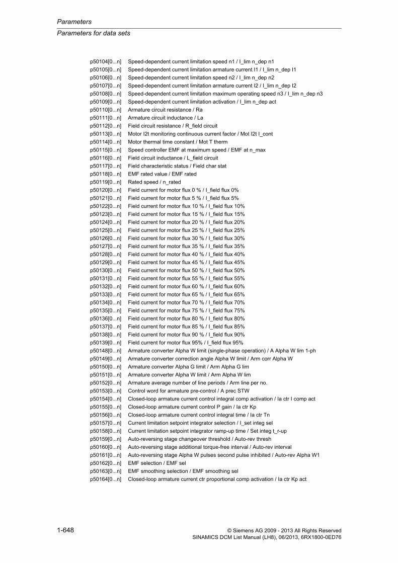
Parameters
Parameters for data sets
1-648 © Siemens AG 2009 - 2013 All Rights ReservedSINAMICS DCM List Manual (LH8), 06/2013, 6RX1800-0ED76
p50104[0...n] Speed-dependent current limitation speed n1 / I_lim n_dep n1
p50105[0...n] Speed-dependent current limitation armature current I1 / I_lim n_dep I1
p50106[0...n] Speed-dependent current limitation speed n2 / I_lim n_dep n2
p50107[0...n] Speed-dependent current limitation armature current I2 / I_lim n_dep I2
p50108[0...n] Speed-dependent current limitation maximum operating speed n3 / I_lim n_dep n3
p50109[0...n] Speed-dependent current limitation activation / I_lim n_dep act
p50110[0...n] Armature circuit resistance / Ra
p50111[0...n] Armature circuit inductance / La
p50112[0...n] Field circuit resistance / R_field circuit
p50113[0...n] Motor I2t monitoring continuous current factor / Mot I2t I_cont
p50114[0...n] Motor thermal time constant / Mot T therm
p50115[0...n] Speed controller EMF at maximum speed / EMF at n_max
p50116[0...n] Field circuit inductance / L_field circuit
p50117[0...n] Field characteristic status / Field char stat
p50118[0...n] EMF rated value / EMF rated
p50119[0...n] Rated speed / n_rated
p50120[0...n] Field current for motor flux 0 % / I_field flux 0%
p50121[0...n] Field current for motor flux 5 % / I_field flux 5%
p50122[0...n] Field current for motor flux 10 % / I_field flux 10%
p50123[0...n] Field current for motor flux 15 % / I_field flux 15%
p50124[0...n] Field current for motor flux 20 % / I_field flux 20%
p50125[0...n] Field current for motor flux 25 % / I_field flux 25%
p50126[0...n] Field current for motor flux 30 % / I_field flux 30%
p50127[0...n] Field current for motor flux 35 % / I_field flux 35%
p50128[0...n] Field current for motor flux 40 % / I_field flux 40%
p50129[0...n] Field current for motor flux 45 % / I_field flux 45%
p50130[0...n] Field current for motor flux 50 % / I_field flux 50%
p50131[0...n] Field current for motor flux 55 % / I_field flux 55%
p50132[0...n] Field current for motor flux 60 % / I_field flux 60%
p50133[0...n] Field current for motor flux 65 % / I_field flux 65%
p50134[0...n] Field current for motor flux 70 % / I_field flux 70%
p50135[0...n] Field current for motor flux 75 % / I_field flux 75%
p50136[0...n] Field current for motor flux 80 % / I_field flux 80%
p50137[0...n] Field current for motor flux 85 % / I_field flux 85%
p50138[0...n] Field current for motor flux 90 % / I_field flux 90%
p50139[0...n] Field current for motor flux 95% / I_field flux 95%
p50148[0...n] Armature converter Alpha W limit (single-phase operation) / A Alpha W lim 1-ph
p50149[0...n] Armature converter correction angle Alpha W limit / Arm corr Alpha W
p50150[0...n] Armature converter Alpha G limit / Arm Alpha G lim
p50151[0...n] Armature converter Alpha W limit / Arm Alpha W lim
p50152[0...n] Armature average number of line periods / Arm line per no.
p50153[0...n] Control word for armature pre-control / A prec STW
p50154[0...n] Closed-loop armature current control integral comp activation / Ia ctr I comp act
p50155[0...n] Closed-loop armature current control P gain / Ia ctr Kp
p50156[0...n] Closed-loop armature current control integral time / Ia ctr Tn
p50157[0...n] Current limitation setpoint integrator selection / I_set integ sel
p50158[0...n] Current limitation setpoint integrator ramp-up time / Set integ t_r-up
p50159[0...n] Auto-reversing stage changeover threshold / Auto-rev thresh
p50160[0...n] Auto-reversing stage additional torque-free interval / Auto-rev interval
p50161[0...n] Auto-reversing stage Alpha W pulses second pulse inhibited / Auto-rev Alpha W1
p50162[0...n] EMF selection / EMF sel
p50163[0...n] EMF smoothing selection / EMF smoothing sel
p50164[0...n] Closed-loop armature current ctr proportional comp activation / Ia ctr Kp act

Parameters for data sets
Parameters
1-649© Siemens AG 2009 - 2013 All Rights ReservedSINAMICS DCM List Manual (LH8), 06/2013, 6RX1800-0ED76
p50169[0...n] Torque limiting selection torque limiting/current limitation / T lim sel T/I_lim
p50170[0...n] Selection of control type for closed-loop current/torque control / Ctrl type I/tq sel
p50171[0...n] Current limitation armature current limit torque dir I factor / Ia lim t d I fact
p50172[0...n] Current limitation armature current limit torque dir II factor / Ia lim t d II fact
p50179[0...n] Auto-reversing stage Alpha W pluses second pulse enabled / Auto-rev Alpha W2
p50180[0...n] Torque limiting torque limit 1 positive / T lim 1 pos
p50181[0...n] Torque limiting torque limit 1 negative / T lim 1 neg
p50182[0...n] Torque limiting torque limit 2 positive / T lim 2 pos
p50183[0...n] Torque limiting torque limit 2 negative / T lim 2 neg
p50184[0...n] Torque limiting changeover speed / T lim n_chng
p50190[0...n] Cl-loop arm current ctr prectr setpoint smoothing time constant / Ia prec set T
p50191[0...n] Cl-loop arm current ctr curr controller setp sm time constant / Ia ctr set T
p50192[0...n] Armature Alpha W limit control word / A Alpha W lim STW
p50200[0...n] Speed controller speed actual value smoothing time constant / n_ctr n_act T
p50201[0...n] Band-stop 1 resonant frequency / Band-st 1 f_n
p50202[0...n] Band-stop 1 quality / Band-st 1 quality
p50203[0...n] Band-stop 2 resonant frequency / Band-st 2 f_n
p50204[0...n] Band-stop 2 quality / Band-st 2 quality
p50205[0...n] Derivative-action element derivative-action time / D-act el t_d-act
p50206[0...n] Derivative-action element smoothing time / Der-act el t_DAE
p50220[0...n] Speed controller changeover PI/P speed setpoint threshold / PI/P n_set thresh
p50221[0...n] Speed controller changeover PI/P hysteresis / PI/P hyst
p50222[0...n] Speed controller changeover PI/P speed actual value threshold / PI/P n_act thresh
p50223[0...n] Speed controller pre-control enable / n_ctr prec ena
p50224[0...n] Speed controller integral component configuration / n_ctr I comp conf
p50225[0...n] Speed controller adaptation Kp y coordinate 2 / Adapt Kp y2
p50226[0...n] Speed controller adaptation Tn y coordinate 2 / Adapt Tn y2
p50228[0...n] Speed controller speed setpoint smoothing time constant / n_ctr n_set T
p50229[0...n] Mast/Sl drive ctr speed controller tracking I component / M/S drve ctr track
p50230[0...n] Set speed controller integral component duration / Set I_comp dur
p50234[0...n] Speed controller proportional component enable / n_ctr P_comp ena
p50237[0...n] Speed controller reference model natural frequency / n_ctrl ref_m fn
p50238[0...n] Speed controller reference model damping / n_ctrl ref_m d
p50239[0...n] Speed controller reference model dead time / n_ctr ref_m t_dead
p50240[0...n] Speed controller reference model activation / n_ctrl ref_m act
p50250[0...n] Field converter Alpha G limit / Field Alpha G lim
p50251[0...n] Field converter Alpha W limit / Field Alpha W lim
p50252[0...n] Field average number of line periods / Field line per no.
p50253[0...n] Field pre-control activation / Field prec act
p50254[0...n] Field current controller integral component activation / I_field_ctr I comp
p50255[0...n] Field current controller P gain / I_field ctr Kp
p50256[0...n] Field current controller integral time / I_field ctr Tn
p50257[0...n] Closed-loop field current control standstill field / If_ctr stst_field
p50258[0...n] Cl-loop field current control field current reduction delay time / If_ctr I_red t_del
p50260[0...n] Field current pre-control setpoint smoothing time constant / Field_prec set T
p50261[0...n] Field current controller setpoint smoothing time constant / I_field_ctr set T
p50263[0...n] Selection of motor flux input variable / Mot fl input sel
p50264[0...n] Field current controller proportional component activation / I_field_ctr P comp
p50273[0...n] EMF controller pre-control activation / EMF ctr prec act
p50274[0...n] EMF controller integral component activation / EMF ctr I comp act
p50275[0...n] EMF controller P gain / EMF ctr Kp
p50276[0...n] EMF controller integral time / EMF ctr Tn
p50277[0...n] EMF controller droop / EMF ctr droop

Parameters
Parameters for data sets
1-650 © Siemens AG 2009 - 2013 All Rights ReservedSINAMICS DCM List Manual (LH8), 06/2013, 6RX1800-0ED76
p50280[0...n] EMF controller pre-control setpoint smoothing time constant / EMF prec set T
p50281[0...n] EMF controller setpoint smoothing time constant / EMF ctr set T
p50282[0...n] EMF controller actual value smoothing time constant / EMF ctr act T
p50283[0...n] EMF controller pre-control actual value smoothing time constant / EMF prec act T
p50284[0...n] EMF controller proportional component activation / EMF ctr P comp act
p50285[0...n] EMF setpoint reduction line voltage smoothing time / EMF set line t_sm
p50286[0...n] EMF setpoint reduction line voltage upper limit / EMF set line upper
p50287[0...n] EMF setpoint reduction line voltage lower limit / EMF set line lower
p50288[0...n] EMF setpoint reduction evaluation factor / EMF set eval_fact
p50295[0...n] Transition rounding operating mode / RFG rounding mode
p50296[0...n] RFG quick stop (OFF3) ramp-down time / RFG OFF3 t_ramp-dn
p50297[0...n] RFG quick stop (OFF3) initial rounding / RFG OFF3 init rndg
p50298[0...n] RFG quick stop (OFF3) final rounding / RFG OFF3 fin rndg
p50300[0...n] RFG positive setpoint limit after ramp-function generator / RFG pos after RFG
p50301[0...n] RFG negative setpoint limit after ramp-function generator / RFG neg after RFG
p50302[0...n] RFG ramp-up integrator operating mode / RFG integ op mode
p50303[0...n] RFG ramp-up time 1 / RFG t_ramp-up 1
p50304[0...n] RFG ramp-down time 1 / RFG t_ramp-dn 1
p50305[0...n] RFG initial rounding 1 / RFG init rndg 1
p50306[0...n] RFG final rounding 1 / RFG fin rndg 1
p50307[0...n] RFG ramp-up time 2 / RFG t_ramp-up 2
p50308[0...n] RFG ramp-down time 2 / RFG ramp-dn time 2
p50309[0...n] RFG initial rounding 2 / RFG init rndg 2
p50310[0...n] RFG final rounding 2 / RFG fin rndg 2
p50311[0...n] RFG ramp-up time 3 / RFG t_ramp-up 3
p50312[0...n] RFG ramp-down time 3 / RFG t_ramp-dn 3
p50313[0...n] RFG initial rounding 3 / RFG init rndg 3
p50314[0...n] RFG final rounding 3 / RFG fin rndg 3
p50317[0...n] RFG tracking enable / RFG track ena
p50318[0...n] RFG setting value selection / RFG set val sel
p50319[0...n] RFG setpoint enable delay time / RFG set_ena i_del
p50320[0...n] Setpoint processing main setpoint factor / m_set_factor
p50321[0...n] Setpoint processing additional setpoint factor / Add_set_factor
p50330[0...n] RFG time unit / RFG time unit
p50351[0...n] Line undervoltage threshold / Line V_und thresh
p50352[0...n] Line overvoltage threshold / Line V_over thresh
p50353[0...n] Line monitoring phase failure threshold / Ph_fail thresh
p50355[0...n] Stall protection monitoring time / Stall t_mon
p50356[0...n] Stall protection threshold / Stall prot thresh
p50357[0...n] Tachometer interruption monitoring threshold / Tacho_mon thresh
p50361[0...n] Line monitoring undervoltage delay time / V_under t_del
p50362[0...n] Line monitoring overvoltage delay time / Line V_over t_del
p50363[0...n] Line frequency minimum threshold / f_line min thresh
p50364[0...n] Line frequency maximum threshold / f_line max thresh
p50370[0...n] Messages for speed less than minimum speed threshold / n < n_min thresh
p50371[0...n] Messages for speed less than minimum speed hysteresis / n < n_min hyst
p50372[0...n] Messages speed positive hysteresis / Msg n > 0 hyst
p50373[0...n] Messages for reference speed threshold / Ref_speed thresh
p50374[0...n] Messages for reference speed hysteresis / Ref_speed hyst
p50375[0...n] Messages for reference speed OFF delay / Ref_speed t_OFF
p50376[0...n] Messages for setpoint/actual value deviation 2 threshold / Set/act 2 thresh
p50377[0...n] Messages for setpoint/actual value deviation 2 hysteresis / Set/act 2 hyst
p50378[0...n] Messages for setpoint/actual value deviation 2 OFF delay / Set/act 2 t_OFF

Parameters for data sets
Parameters
1-651© Siemens AG 2009 - 2013 All Rights ReservedSINAMICS DCM List Manual (LH8), 06/2013, 6RX1800-0ED76
p50380[0...n] Messages for overspeed threshold positive direction of rotation / Msg n_over pos
p50381[0...n] Messages for overspeed threshold negative direction of rotation / Msg n_over neg
p50388[0...n] Messages for setpoint/actual value deviation 1 threshold / Set/act 1 thresh
p50389[0...n] Messages for setpoint/actual value deviation 1 hysteresis / Set/act 1 hyst
p50390[0...n] Messages for setpoint/actual value deviation 1 OFF delay / Set/act t_OFF
p50394[0...n] Messages for field current threshold minimum threshold / Msg If min thresh
p50395[0...n] Messages for field current threshold minimum hysteresis / Msg If min hyst
p50396[0...n] Field current monitoring setpoint factor / If_mon set_fact
p50397[0...n] Field current monitoring fault delay time / If_mon F t_del
p50398[0...n] Messages for field current actual value less than setpoint fact / Msg If<set fact
p50399[0...n] Messages for field current actual value less than setpoint hyst / Msg If<set hyst
p50401[0...n] Fixed value 1 / Fix val 1
p50402[0...n] Fixed value 2 / Fix val 2
p50403[0...n] Fixed value 3 / Fix val 3
p50404[0...n] Fixed value 4 / Fix val 4
p50405[0...n] Fixed value 5 / Fix val 5
p50406[0...n] Fixed value 6 / Fix val 6
p50407[0...n] Fixed value 7 / Fix val 7
p50408[0...n] Fixed value 8 / Fix val 8
p50409[0...n] Fixed value 9 / Fix val 9
p50410[0...n] Fixed value 10 / Fix val 10
p50411[0...n] Fixed value 11 / Fix val 11
p50412[0...n] Fixed value 12 / Fix val 12
p50413[0...n] Fixed value 13 / Fix val 13
p50414[0...n] Fixed value 14 / Fix val 14
p50415[0...n] Fixed value 15 / Fix val 15
p50416[0...n] Fixed value 16 / Fix val 16
p50421[0...n] Fixed bit 0 / Fixed bit 0
p50422[0...n] Fixed bit 1 / Fixed bit 1
p50423[0...n] Fixed bit 2 / Fixed bit 2
p50424[0...n] Fixed bit 3 / Fixed bit 3
p50425[0...n] Fixed bit 4 / Fixed bit 4
p50426[0...n] Fixed bit 5 / Fixed bit 5
p50427[0...n] Fixed bit 6 / Fixed bit 6
p50428[0...n] Fixed bit 7 / Fixed bit 7
p50460[0...n] Motorized potentiometer activate ramp-function generator / Mot pot act RFG
p50462[0...n] Motorized potentiometer ramp-up time / MotP t_r-up
p50463[0...n] Motorized potentiometer ramp-down time / MotP t_r-dn
p50464[0...n] Motorized potentiometer time difference for dy/dt / MotP t_dif dy/dt
p50465[0...n] Motorized potentiometer expansion factor / MotP exp fact
p50467[0...n] Motorized potentiometer starting value / MotP start value
p50468[0...n] Motorized potentiometer maximum speed / MotP n_max
p50469[0...n] Motorized potentiometer minimum speed / MotP n_min
p50473[0...n] Motorized potentiometer save output value / MotP save outp val
p50480[0...n] Oscillation setpoint 1 / Oscillation set 1
p50481[0...n] Oscillation setpoint 1 time / Oscill set 1 t
p50482[0...n] Oscillation setpoint 2 / Oscillation set 2
p50483[0...n] Oscillation setpoint 2 time / Oscill set 2 t
p50491[0...n] Motor interface alarm threshold for temperature monitoring / Mot_temp al thr
p50492[0...n] Motor interface fault threshold for temperature monitoring / Mot_temp flt thr
p50503[0...n] Torque limiting t_set factor in slave mode / T_set fact sl mode
p50512[0...n] Speed limiting controller max speed pos direction of rotation / n_max pos dir rot
p50513[0...n] Speed limiting controller max speed neg direction of rotation / n_max neg dir

Parameters
Parameters for data sets
1-652 © Siemens AG 2009 - 2013 All Rights ReservedSINAMICS DCM List Manual (LH8), 06/2013, 6RX1800-0ED76
p50515[0...n] Speed limiting controller P gain / n_lim Kp
p50520[0...n] Friction compensation 0 % speed / Fric comp n 0%
p50521[0...n] Friction compensation 10 % speed / Fric comp n 10%
p50522[0...n] Friction compensation 20 % speed / Fric comp n 20%
p50523[0...n] Friction compensation 30 % speed / Fric comp n 30%
p50524[0...n] Friction compensation 40 % speed / Fric comp n 40%
p50525[0...n] Friction compensation 50 % speed / Fric comp n 50%
p50526[0...n] Friction compensation 60 % speed / Fric comp n 60%
p50527[0...n] Friction compensation 70 % speed / Fric comp n 70%
p50528[0...n] Friction compensation 80 % speed / Fric comp n 80%
p50529[0...n] Friction compensation 90 % speed / Fric comp n 90%
p50530[0...n] Friction compensation 100% speed / Fric comp n 100%
p50540[0...n] Speed controller acceleration time / n_ctr t_accel
p50542[0...n] RFG dy/dt time difference / RFG dy/dt t_dif
p50543[0...n] Speed controller setpoint/actual value difference threshold / Set/act dif thresh
p50546[0...n] Smoothing time constant for inertia compensation / Comp inert T
p50550[0...n] Speed controller adaptation Kp y coordinate 1 / Adapt Kp y1
p50551[0...n] Speed controller adaptation Tn y coordinate 1 / Adapt Tn y1
p50556[0...n] Speed controller adaptation Kp x coordinate 1 / Adapt Kp x1
p50557[0...n] Speed controller adaptation Tn x coordinate 1 / Adapt Tn x1
p50559[0...n] Speed controller adaptation Kp x coordinate 2 / Adapt Kp x2
p50560[0...n] Speed controller adaptation Tn x coordinate 2 / Adapt Tn x2
p50561[0...n] Speed controller adaptation droop x coordinate 2 / Adapt droop x2
p50562[0...n] Speed controller droop positive limiting / Droop pos lim
p50563[0...n] Speed controller droop negative limiting / Droop neg lim
p50570[0...n] Adaptation armature current controller changeover input / Adapt Ia chgov inp
p50571[0...n] Adaptation armature current controller non-linear L activation / Adapt N_lin L act
p50572[0...n] Adapt arm curr controller intermittent adapt activation / Adapt Interm Act
p50573[0...n] Adaptation armature current controller limiting / Adapt Ia_ctrl lim
p50574[0...n] Adapt arm curr controller intermittent adapt Kp increase / Ad Interm Kp incr
p50575[0...n] Adaptation field current controller changeover input / Adapt If chgov inp
p50576[0...n] Adaptation field current controller non-linear L activation / Adapt n_lin act
p50577[0...n] Adapt field curr controller non-linear gating unit activation / Adapt n_lin GU act
p50578[0...n] Adaptation field current controller limiting / Adapt If_ctrl lim
p50701[0...n] CUD analog input 0 scaling / CUD AI 0 scal
p50711[0...n] CUD analog input 1 scaling / CUD AI 1 scal
p50721[0...n] CUD analog input 2 scaling / CUD AI 2 scal
p50741[0...n] Analog input main actual value scaling / AI m act scal
p51591[0...n] Armature inductance reduction factor / L_armat red fact
p51592[0...n] Armature commutating inductance / Arm Lk
p51594[0...n] Interphase inductance in 12-pulse operation / L_intph 12-pulse
p51595[0...n] Interphase inductance reduction factor / L_intph red fact
p51596[0...n] Interphase resistance in 12-pulse operation / R_intph 12-pulse
p51597[0...n] Field inductance reduction factor / L_field red fact
p51608[0...n] Setpoint processing reduction factor / Red factor
p51651[0...n] Speed controller start pulse positive setpoint / Start pul pos set
p51652[0...n] Speed controller start pulse negative factor / Start pul neg fact
p51653[0...n] Speed controller start pulse negative setpoint / Start pul neg set

Parameters for data sets
Parameters
1-653© Siemens AG 2009 - 2013 All Rights ReservedSINAMICS DCM List Manual (LH8), 06/2013, 6RX1800-0ED76
1.3.3 Parameters for encoder data sets (EDS)
The following list contains the parameters that are dependent on the encoder data sets.
Product: SINAMICS DC MASTER, Version: 4601800, Language: eng, Type: EDS
p0141[0...n] Encoder interface (Sensor Module) component number / Enc_interf comp_no
p0142[0...n] Encoder component number / Encoder comp_no
p0144[0...n] Sensor Module detection via LED / SM detection LED
p0145[0...n] Activate/de-activate encoder interface / Enc_intf act/deact
r0146[0...n] Encoder interface active/inactive / Enc_intf act/inact
r0147[0...n] Sensor Module EEPROM data version / SM EEPROM version
r0148[0...n] Sensor Module firmware version / SM FW version
p0400[0...n] Encoder type selection / Enc_typ sel
p0401[0...n] Encoder type OEM selection / Enc type OEM sel
p0402[0...n] Gearbox type selection / Gearbox type sel
p0404[0...n] Encoder configuration effective / Enc_config eff
p0405[0...n] Square-wave encoder track A/B / Sq-wave enc A/B
p0407[0...n] Linear encoder grid division / Enc grid div
p0408[0...n] Rotary encoder pulse number / Rot enc pulse No.
p0410[0...n] Encoder inversion actual value / Enc inv act value
p0411[0...n] Measuring gear configuration / Meas gear config
p0412[0...n] Measuring gear absolute encoder rotary revolutions virtual / Abs rot rev
p0413[0...n] Measuring gear position tracking tolerance window / Pos track window
p0414[0...n] Redundant coarse position value relevant bits (identified) / Relevant bits
p0415[0...n] Gx_XIST1 Coarse position safe most significant bit (identified) / Gx_XIST1 safe MSB
p0416[0...n] Non safety-relevant meas. steps position value pos1 (detected) / nsrPos1
p0417[0...n] Encoder safety comparison algorithm (detected) / Safety comp_algo
p0418[0...n] Fine resolution Gx_XIST1 (in bits) / Enc fine Gx_XIST1
p0419[0...n] Fine resolution absolute value Gx_XIST2 (in bits) / Enc fine Gx_XIST2
p0420[0...n] Encoder connection / Enc_connection
p0421[0...n] Absolute encoder rotary multiturn resolution / Enc abs multiturn
p0422[0...n] Absolute encoder linear measuring step resolution / Enc abs meas step
p0423[0...n] Absolute encoder rotary singleturn resolution / Enc abs singleturn
p0424[0...n] Encoder linear zero mark distance / Enc lin ZM_dist
p0425[0...n] Encoder rotary zero mark distance / Enc rot dist ZM
p0426[0...n] Encoder zero mark differential distance / Enc ZM Dif_dist
p0427[0...n] Encoder SSI baud rate / Enc SSI baud rate
p0428[0...n] Encoder SSI monoflop time / Enc SSI t_monoflop
p0429[0...n] Encoder SSI configuration / Enc SSI config
p0430[0...n] Sensor Module configuration / SM config
p0431[0...n] Angular commutation offset / Ang_com offset
p0432[0...n] Gearbox factor encoder revolutions / Grbx_fact enc_rev
p0433[0...n] Gearbox factor motor/load revolutions / Grbx_fact mot_rev
p0434[0...n] Encoder SSI error bit / Enc SSI error bit
p0435[0...n] Encoder SSI alarm bit / Enc SSI alarm bit
p0436[0...n] Encoder SSI parity bit / Enc SSI parity bit
p0437[0...n] Sensor Module configuration extended / SM config ext
Note:
References: SINAMICS DC MASTER operating instructions“Data sets” Chapter

Parameters
Parameters for data sets
1-654 © Siemens AG 2009 - 2013 All Rights ReservedSINAMICS DCM List Manual (LH8), 06/2013, 6RX1800-0ED76
p0438[0...n] Squarewave encoder filter time / Enc t_filt
p0439[0...n] Encoder ramp-up time / Enc ramp-up time
p0440[0...n] Copy encoder serial number / Copy enc ser_no
p0441[0...n] Encoder commissioning serial number part 1 / Enc comm ser_no 1
p0442[0...n] Encoder commissioning serial number part 2 / Enc comm ser_no 2
p0443[0...n] Encoder commissioning serial number part 3 / Enc comm ser_no 3
p0444[0...n] Encoder commissioning serial number part 4 / Enc comm ser_no 4
p0445[0...n] Encoder commissioning serial number part 5 / Enc comm ser_no 5
p0453[0...n] Pulse encoder evaluation zero speed measuring time / Enc_ev n_0 t_meas
p4678[0...n] Analog sensor LVDT ratio / An_sens LVDT ratio
p4679[0...n] Analog sensor LVDT phase / An_sens LVDT ph
p4680[0...n] Zero mark monitoring tolerance permissible / ZM_monit tol perm
p4681[0...n] Zero mark monitoring tolerance window limit 1 positive / ZM tol lim 1 pos
p4682[0...n] Zero mark monitoring tolerance window limit 1 negative / ZM tol lim 1 neg
p4683[0...n] Zero mark monitoring tolerance window alarm threshold positive / ZM tol A_thr pos
p4684[0...n] Zero mark monitoring tolerance window alarm threshold negative / ZM tol A_thr neg
p4685[0...n] Speed actual value mean value generation / n_act mean val
p4686[0...n] Zero mark minimum length / ZM min length
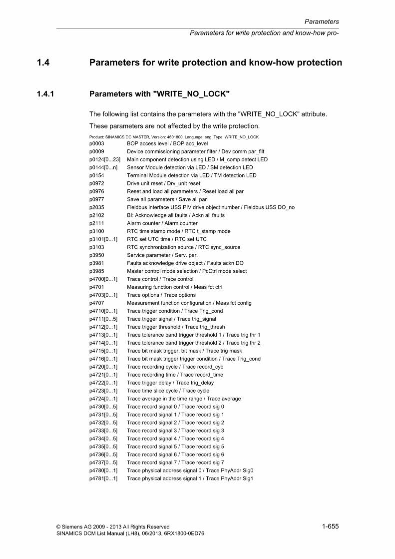
Parameters for write protection and know-how pro-
Parameters
1-655© Siemens AG 2009 - 2013 All Rights ReservedSINAMICS DCM List Manual (LH8), 06/2013, 6RX1800-0ED76
1.4 Parameters for write protection and know-how protection
1.4.1 Parameters with "WRITE_NO_LOCK"
The following list contains the parameters with the "WRITE_NO_LOCK" attribute.
These parameters are not affected by the write protection.
Product: SINAMICS DC MASTER, Version: 4601800, Language: eng, Type: WRITE_NO_LOCK
p0003 BOP access level / BOP acc_level
p0009 Device commissioning parameter filter / Dev comm par_filt
p0124[0...23] Main component detection using LED / M_comp detect LED
p0144[0...n] Sensor Module detection via LED / SM detection LED
p0154 Terminal Module detection via LED / TM detection LED
p0972 Drive unit reset / Drv_unit reset
p0976 Reset and load all parameters / Reset load all par
p0977 Save all parameters / Save all par
p2035 Fieldbus interface USS PIV drive object number / Fieldbus USS DO_no
p2102 BI: Acknowledge all faults / Ackn all faults
p2111 Alarm counter / Alarm counter
p3100 RTC time stamp mode / RTC t_stamp mode
p3101[0...1] RTC set UTC time / RTC set UTC
p3103 RTC synchronization source / RTC sync_source
p3950 Service parameter / Serv. par.
p3981 Faults acknowledge drive object / Faults ackn DO
p3985 Master control mode selection / PcCtrl mode select
p4700[0...1] Trace control / Trace control
p4701 Measuring function control / Meas fct ctrl
p4703[0...1] Trace options / Trace options
p4707 Measurement function configuration / Meas fct config
p4710[0...1] Trace trigger condition / Trace Trig_cond
p4711[0...5] Trace trigger signal / Trace trig_signal
p4712[0...1] Trace trigger threshold / Trace trig_thresh
p4713[0...1] Trace tolerance band trigger threshold 1 / Trace trig thr 1
p4714[0...1] Trace tolerance band trigger threshold 2 / Trace trig thr 2
p4715[0...1] Trace bit mask trigger, bit mask / Trace trig mask
p4716[0...1] Trace bit mask trigger trigger condition / Trace Trig_cond
p4720[0...1] Trace recording cycle / Trace record_cyc
p4721[0...1] Trace recording time / Trace record_time
p4722[0...1] Trace trigger delay / Trace trig_delay
p4723[0...1] Trace time slice cycle / Trace cycle
p4724[0...1] Trace average in the time range / Trace average
p4730[0...5] Trace record signal 0 / Trace record sig 0
p4731[0...5] Trace record signal 1 / Trace record sig 1
p4732[0...5] Trace record signal 2 / Trace record sig 2
p4733[0...5] Trace record signal 3 / Trace record sig 3
p4734[0...5] Trace record signal 4 / Trace record sig 4
p4735[0...5] Trace record signal 5 / Trace record sig 5
p4736[0...5] Trace record signal 6 / Trace record sig 6
p4737[0...5] Trace record signal 7 / Trace record sig 7
p4780[0...1] Trace physical address signal 0 / Trace PhyAddr Sig0
p4781[0...1] Trace physical address signal 1 / Trace PhyAddr Sig1

Parameters
Parameters for write protection and know-how protection
1-656 © Siemens AG 2009 - 2013 All Rights ReservedSINAMICS DCM List Manual (LH8), 06/2013, 6RX1800-0ED76
p4782[0...1] Trace physical address signal 2 / Trace PhyAddr Sig2
p4783[0...1] Trace physical address signal 3 / Trace PhyAddr Sig3
p4784[0...1] Trace physical address signal 4 / Trace PhyAddr Sig4
p4785[0...1] Trace physical address signal 5 / Trace PhyAddr Sig5
p4786[0...1] Trace physical address signal 6 / Trace PhyAddr Sig6
p4787[0...1] Trace physical address signal 7 / Trace PhyAddr Sig7
p4789[0...1] Trace physical address trigger signal / Trace PhyAddr Trig
p4795 Trace memory bank changeover / Trace mem changeov
p4800 Function generator control / FG control
p4810 Function generator mode / FG operating mode
p4812 Function generator physical address / FG phys address
p4813 Function generator physical address reference value / FG phys addr ref
p4816 Function generator output signal integer number scaling / FG outp integ scal
p4819 BI: Function generator control / FG control
p4820 Function generator signal shape / FG signal shape
p4821 Function generator period / FG period duration
p4822 Function generator pulse width / FG pulse width
p4823 Function generator bandwidth / FG bandwidth
p4824 Function generator amplitude / FG amplitude
p4825 Function generator 2nd amplitude / FG 2nd amplitude
p4826 Function generator offset / FG offset
p4827 Function generator ramp-up time to offset / FG ramp-up offset
p4828 Function generator lower limit / FG lower limit
p4829 Function generator upper limit / FG upper limit
p4830 Function generator time slice cycle / FG time slice
p4831 Function generator amplitude scaling / FG amplitude scal
p4832[0...2] Function generator amplitude scaling / FG amplitude scal
p4833[0...2] Function generator offset scaling / FG offset scal
p4835[0...4] Function generator free measurement function scaling / FG fr MeasFct scal
p4840[0...1] MTrace cycle number setting / Cycle number
p7761 Write protection / Write protection
p7770 NVRAM action / NVRAM action
p8550 AOP LOCAL/REMOTE / AOP LOCAL/REMOTE
p8829 CBE20 remote controller number / CBE20 rem ctrl num
p9210 Flashing component number / Flash comp_no
p9211 Flash function / Flash fct.
p9400 Safely remove memory card / Mem_card rem
p9484 BICO interconnections search signal source / BICO S_src srch
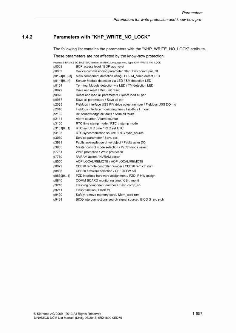
Parameters for write protection and know-how pro-
Parameters
1-657© Siemens AG 2009 - 2013 All Rights ReservedSINAMICS DCM List Manual (LH8), 06/2013, 6RX1800-0ED76
1.4.2 Parameters with "KHP_WRITE_NO_LOCK"
The following list contains the parameters with the "KHP_WRITE_NO_LOCK" attribute.
These parameters are not affected by the know-how protection.
Product: SINAMICS DC MASTER, Version: 4601800, Language: eng, Type: KHP_WRITE_NO_LOCK
p0003 BOP access level / BOP acc_level
p0009 Device commissioning parameter filter / Dev comm par_filt
p0124[0...23] Main component detection using LED / M_comp detect LED
p0144[0...n] Sensor Module detection via LED / SM detection LED
p0154 Terminal Module detection via LED / TM detection LED
p0972 Drive unit reset / Drv_unit reset
p0976 Reset and load all parameters / Reset load all par
p0977 Save all parameters / Save all par
p2035 Fieldbus interface USS PIV drive object number / Fieldbus USS DO_no
p2040 Fieldbus interface monitoring time / Fieldbus t_monit
p2102 BI: Acknowledge all faults / Ackn all faults
p2111 Alarm counter / Alarm counter
p3100 RTC time stamp mode / RTC t_stamp mode
p3101[0...1] RTC set UTC time / RTC set UTC
p3103 RTC synchronization source / RTC sync_source
p3950 Service parameter / Serv. par.
p3981 Faults acknowledge drive object / Faults ackn DO
p3985 Master control mode selection / PcCtrl mode select
p7761 Write protection / Write protection
p7770 NVRAM action / NVRAM action
p8550 AOP LOCAL/REMOTE / AOP LOCAL/REMOTE
p8829 CBE20 remote controller number / CBE20 rem ctrl num
p8835 CBE20 firmware selection / CBE20 FW sel
p8839[0...1] PZD interface hardware assignment / PZD IF HW assign
p8840 COMM BOARD monitoring time / CB t_monit
p9210 Flashing component number / Flash comp_no
p9211 Flash function / Flash fct.
p9400 Safely remove memory card / Mem_card rem
p9484 BICO interconnections search signal source / BICO S_src srch

Parameters
Parameters for write protection and know-how protection
1-658 © Siemens AG 2009 - 2013 All Rights ReservedSINAMICS DCM List Manual (LH8), 06/2013, 6RX1800-0ED76
1.4.3 Parameters with "KHP_ACTIVE_READ"
The following list contains the parameters with the "KHP_ACTIVE_READ" attribute.
These parameters can also be read with activated know-how protection.
Product: SINAMICS DC MASTER, Version: 4601800, Language: eng, Type: KHP_ACTIVE_READ
p0015 Macro drive unit / Macro drv unit
p0015 Macro drive object / Macro DO
p0101[0...23] Drive object numbers / DO numbers
p0103[0...23] Application-specific view / Appl_spec view
p0105 Activate/de-activate drive object / DO act/deact
p0107[0...23] Drive object type / DO type
p0108[0...23] Drive objects function module / DO function module
p0121[0...n] Power unit component number / PU comp_no
p0125[0...n] Activate/de-activate power unit components / PU_comp act/deact
p0140 Number of Encoder Data Sets (EDS) / EDS count
p0141[0...n] Encoder interface (Sensor Module) component number / Enc_interf comp_no
p0142[0...n] Encoder component number / Encoder comp_no
p0145[0...n] Activate/de-activate encoder interface / Enc_intf act/deact
p0151 Terminal Module component number / TM comp_no
p0170 Number of Command Data Sets (CDS) / CDS count
p0180 Number of Drive Data Sets (DDS) / DDS count
p0199[0...24] Drive object name / DO name
p0400[0...n] Encoder type selection / Enc_typ sel
p0595 Technological unit selection / Tech unit select
p0806 BI: Inhibit master control / PcCtrl inhibit
p0922 IF1 PROFIdrive PZD telegram selection / IF1 PZD telegr
p0978[0...24] List of drive objects / List of the DO
p2000 Reference speed / n_ref
p2001 Reference voltage / Reference voltage
p2002 Reference current / I_ref
p2003 Reference torque / M_ref
p2005 Reference angle / Reference angle
p2006 Reference temp / Ref temp
p2007 Reference acceleration / a_ref
p2030 Field bus int protocol selection / Field bus protocol
p2038 IF1 PROFIdrive STW/ZSW interface mode / PD STW/ZSW IF mode
p2079 IF1 PROFIdrive PZD telegram selection extended / IF1 PZD telegr ext
p4956[0...n] OA application activation / OA act
p7763 KHP OEM exception list number of indices for p7764 / KHP OEM qty p7764
p7764[0...n] KHP OEM exception list / KHP OEM excep list
p7852 Number of indices for r7853 / Qty indices r7853
p9902 Target topology number of indices / TargetTopo indices

2-659© Siemens AG 2009 - 2013 All Rights ReservedSINAMICS DCM List Manual (LH8), 06/2013, 6RX1800-0ED76
Function diagrams 2Content
2.1 Table of contents 2-660
2.2 Explanation of the function diagrams 2-666
2.3 Overviews 2-671
2.4 CUD input/output terminals 2-679
2.5 PROFIdrive 2-690
2.6 Internal control/status words 2-715
2.7 Sequence control 2-722
2.8 Brake control 2-727
2.9 Setpoint channel 2-729
2.10 Encoder evaluation 2-743
2.11 Armature circuit closed-loop control 2-751
2.12 Field circuit closed-loop control 2-774
2.13 Power unit 2-783
2.14 Technology controller 2-792
2.15 Signals and monitoring functions 2-794
2.16 Faults and alarms 2-811
2.17 Data sets 2-816
2.18 Communication between devices 2-820
2.19 Terminal Module 15 for SINAMICS (TM15DI/DO) 2-826
2.20 Terminal Module 31 (TM31) 2-830
2.21 Terminal Module 150 (TM150) 2-841
2.22 Basic Operator Panel 20 (BOP20) 2-845

Function diagrams
Table of contents
2-660 © Siemens AG 2009 - 2013 All Rights ReservedSINAMICS DCM List Manual (LH8), 06/2013, 6RX1800-0ED76
2.1 Table of contents
2.2 Explanation of the function diagrams . . . . . . . . . . . . . . . . . . . . . . . . . . . . . . 2-666
1020 – Explanation of the symbols (part 1) . . . . . . . . . . . . . . . . . . . . . . . . . . . . . . . . . . 2-667
1021 – Explanation of the symbols (part 2) . . . . . . . . . . . . . . . . . . . . . . . . . . . . . . . . . . 2-668
1022 – Explanation of the symbols (part 3) . . . . . . . . . . . . . . . . . . . . . . . . . . . . . . . . . . 2-669
1030 – Handling BICO technology . . . . . . . . . . . . . . . . . . . . . . . . . . . . . . . . . . . . . . . . . 2-670
2.3 Overviews . . . . . . . . . . . . . . . . . . . . . . . . . . . . . . . . . . . . . . . . . . . . . . . . . . . . . 2-671
1520 – PROFIdrive . . . . . . . . . . . . . . . . . . . . . . . . . . . . . . . . . . . . . . . . . . . . . . . . . . . . 2-672
1580 – Encoder evaluations (position, speed) . . . . . . . . . . . . . . . . . . . . . . . . . . . . . . . . 2-673
1720 – Closed-loop control . . . . . . . . . . . . . . . . . . . . . . . . . . . . . . . . . . . . . . . . . . . . . . 2-674
1721 – Activation/deactivation of closed-loop control functions . . . . . . . . . . . . . . . . . . . 2-675
1722 – CUD left, CUD right . . . . . . . . . . . . . . . . . . . . . . . . . . . . . . . . . . . . . . . . . . . . . . 2-676
1781 – Terminal Module 15 for SINAMICS (TM15DI/DO) . . . . . . . . . . . . . . . . . . . . . . . 2-677
1840 – Terminal Module 31 (TM31) . . . . . . . . . . . . . . . . . . . . . . . . . . . . . . . . . . . . . . . . 2-678
2.4 CUD input/output terminals . . . . . . . . . . . . . . . . . . . . . . . . . . . . . . . . . . . . . . . 2-679
2050 – Digital inputs (DI 0 ... DI 3) . . . . . . . . . . . . . . . . . . . . . . . . . . . . . . . . . . . . . . . . . 2-680
2055 – Digital outputs (DO 0 ... DO 3) . . . . . . . . . . . . . . . . . . . . . . . . . . . . . . . . . . . . . . 2-681
2060 – Digital inputs/outputs, bidirectional (DI/DO 4 ... DI/DO 5) . . . . . . . . . . . . . . . . . 2-682
2065 – Digital inputs/outputs, bidirectional (DI/DO 6 ... DI/DO 7) . . . . . . . . . . . . . . . . . 2-683
2070 – E stop (emergency stop), relay output main contactor . . . . . . . . . . . . . . . . . . . 2-684
2075 – Analog inputs (AI 0 and XT1.103/104) . . . . . . . . . . . . . . . . . . . . . . . . . . . . . . . . 2-685
2080 – Analog inputs (AI 1 ... AI 2) . . . . . . . . . . . . . . . . . . . . . . . . . . . . . . . . . . . . . . . . 2-686
2085 – Analog inputs (AI 3 ... AI 4) . . . . . . . . . . . . . . . . . . . . . . . . . . . . . . . . . . . . . . . . 2-687
2090 – Analog inputs (AI 5 ... AI 6) . . . . . . . . . . . . . . . . . . . . . . . . . . . . . . . . . . . . . . . . 2-688
2095 – Analog outputs (AO 0 ... AO 1) . . . . . . . . . . . . . . . . . . . . . . . . . . . . . . . . . . . . . 2-689
2.5 PROFIdrive . . . . . . . . . . . . . . . . . . . . . . . . . . . . . . . . . . . . . . . . . . . . . . . . . . . . 2-690
2410 – PROFIBUS (PB) / PROFINET (PN) / USS, addresses and diagnostics . . . . . . 2-691
2420 – Telegrams and process data (PZD) . . . . . . . . . . . . . . . . . . . . . . . . . . . . . . . . . . 2-692
2425 – STW1_BM control word metal industry interconnection . . . . . . . . . . . . . . . . . . 2-693
2426 – STW2_BM control word metal industry interconnection . . . . . . . . . . . . . . . . . . 2-694
2428 – ZSW1_BM status word metal industry interconnection . . . . . . . . . . . . . . . . . . . 2-695
2429 – ZSW2_BM status word metal industry interconnection . . . . . . . . . . . . . . . . . . . 2-696
2440 – PZD receive signals interconnection . . . . . . . . . . . . . . . . . . . . . . . . . . . . . . . . . 2-697

Table of contents
Function diagrams
2-661© Siemens AG 2009 - 2013 All Rights ReservedSINAMICS DCM List Manual (LH8), 06/2013, 6RX1800-0ED76
2442 – STW1 control word interconnection . . . . . . . . . . . . . . . . . . . . . . . . . . . . . . . . . . 2-698
2444 – STW2 control word interconnection . . . . . . . . . . . . . . . . . . . . . . . . . . . . . . . . . . 2-699
2450 – PZD send signals interconnection . . . . . . . . . . . . . . . . . . . . . . . . . . . . . . . . . . . 2-700
2452 – ZSW1 status word interconnection . . . . . . . . . . . . . . . . . . . . . . . . . . . . . . . . . . 2-701
2454 – ZSW2 status word interconnection . . . . . . . . . . . . . . . . . . . . . . . . . . . . . . . . . . 2-702
2460 – IF1 receive telegram, free interconnection via BICO (p0922 = 999) . . . . . . . . . 2-703
2470 – IF1 send telegram, free interconnection via BICO (p0922 = 999) . . . . . . . . . . . 2-704
2472 – IF1 status words, free interconnection . . . . . . . . . . . . . . . . . . . . . . . . . . . . . . . . 2-705
2481 – IF1 receive telegram, free interconnection via BICO (p0922 = 999) . . . . . . . . . 2-706
2483 – IF1 send telegram, free interconnection via BICO (p0922 = 999) . . . . . . . . . . . 2-707
2485 – IF2 receive telegram, free interconnection via BICO (p0922 = 999) . . . . . . . . . 2-708
2487 – IF2 send telegram, free interconnection via BICO (p0922 = 999) . . . . . . . . . . . 2-709
2489 – IF2 status words, free interconnection . . . . . . . . . . . . . . . . . . . . . . . . . . . . . . . . 2-710
2495 – CU_STW1 control word 1, Control Unit interconnection . . . . . . . . . . . . . . . . . . 2-711
2496 – CU_ZSW1 status word 1, Control Unit interconnection . . . . . . . . . . . . . . . . . . . 2-712
2497 – A_DIGITAL interconnection . . . . . . . . . . . . . . . . . . . . . . . . . . . . . . . . . . . . . . . . 2-713
2498 – E_DIGITAL interconnection . . . . . . . . . . . . . . . . . . . . . . . . . . . . . . . . . . . . . . . . 2-714
2.6 Internal control/status words . . . . . . . . . . . . . . . . . . . . . . . . . . . . . . . . . . . . . 2-715
2534 – Status word, monitoring functions 1 . . . . . . . . . . . . . . . . . . . . . . . . . . . . . . . . . . 2-716
2537 – Status word, monitoring functions 3 . . . . . . . . . . . . . . . . . . . . . . . . . . . . . . . . . . 2-717
2546 – Control word faults/alarms . . . . . . . . . . . . . . . . . . . . . . . . . . . . . . . . . . . . . . . . . 2-718
2548 – Status word faults/alarms 1 and 2 . . . . . . . . . . . . . . . . . . . . . . . . . . . . . . . . . . . 2-719
2580 – Control word sequence control . . . . . . . . . . . . . . . . . . . . . . . . . . . . . . . . . . . . . 2-720
2585 – Status word sequence control . . . . . . . . . . . . . . . . . . . . . . . . . . . . . . . . . . . . . . 2-721
2.7 Sequence control . . . . . . . . . . . . . . . . . . . . . . . . . . . . . . . . . . . . . . . . . . . . . . . 2-722
2650 – Sequencer (Part 1) . . . . . . . . . . . . . . . . . . . . . . . . . . . . . . . . . . . . . . . . . . . . . . . 2-723
2651 – Sequencer (Part 2) . . . . . . . . . . . . . . . . . . . . . . . . . . . . . . . . . . . . . . . . . . . . . . . 2-724
2655 – Missing enable signals, logic operations . . . . . . . . . . . . . . . . . . . . . . . . . . . . . . 2-725
2660 – Optimization runs . . . . . . . . . . . . . . . . . . . . . . . . . . . . . . . . . . . . . . . . . . . . . . . . 2-726
2.8 Brake control . . . . . . . . . . . . . . . . . . . . . . . . . . . . . . . . . . . . . . . . . . . . . . . . . . . 2-727
2750 – Brake control . . . . . . . . . . . . . . . . . . . . . . . . . . . . . . . . . . . . . . . . . . . . . . . . . . . 2-728
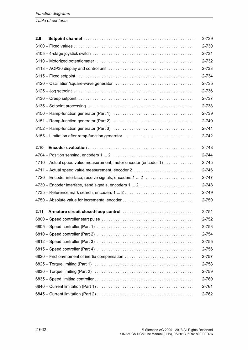
Function diagrams
Table of contents
2-662 © Siemens AG 2009 - 2013 All Rights ReservedSINAMICS DCM List Manual (LH8), 06/2013, 6RX1800-0ED76
2.9 Setpoint channel . . . . . . . . . . . . . . . . . . . . . . . . . . . . . . . . . . . . . . . . . . . . . . . . 2-729
3100 – Fixed values . . . . . . . . . . . . . . . . . . . . . . . . . . . . . . . . . . . . . . . . . . . . . . . . . . . . 2-730
3105 – 4-stage joystick switch . . . . . . . . . . . . . . . . . . . . . . . . . . . . . . . . . . . . . . . . . . . . 2-731
3110 – Motorized potentiometer . . . . . . . . . . . . . . . . . . . . . . . . . . . . . . . . . . . . . . . . . . 2-732
3113 – AOP30 display and control unit . . . . . . . . . . . . . . . . . . . . . . . . . . . . . . . . . . . . . 2-733
3115 – Fixed setpoint . . . . . . . . . . . . . . . . . . . . . . . . . . . . . . . . . . . . . . . . . . . . . . . . . . . 2-734
3120 – Oscillation/square-wave generator . . . . . . . . . . . . . . . . . . . . . . . . . . . . . . . . . . 2-735
3125 – Jog setpoint . . . . . . . . . . . . . . . . . . . . . . . . . . . . . . . . . . . . . . . . . . . . . . . . . . . . 2-736
3130 – Creep setpoint . . . . . . . . . . . . . . . . . . . . . . . . . . . . . . . . . . . . . . . . . . . . . . . . . . 2-737
3135 – Setpoint processing . . . . . . . . . . . . . . . . . . . . . . . . . . . . . . . . . . . . . . . . . . . . . . 2-738
3150 – Ramp-function generator (Part 1) . . . . . . . . . . . . . . . . . . . . . . . . . . . . . . . . . . . 2-739
3151 – Ramp-function generator (Part 2) . . . . . . . . . . . . . . . . . . . . . . . . . . . . . . . . . . . 2-740
3152 – Ramp-function generator (Part 3) . . . . . . . . . . . . . . . . . . . . . . . . . . . . . . . . . . . 2-741
3155 – Limitation after ramp-function generator . . . . . . . . . . . . . . . . . . . . . . . . . . . . . . 2-742
2.10 Encoder evaluation . . . . . . . . . . . . . . . . . . . . . . . . . . . . . . . . . . . . . . . . . . . . . . 2-743
4704 – Position sensing, encoders 1 ... 2 . . . . . . . . . . . . . . . . . . . . . . . . . . . . . . . . . . . 2-744
4710 – Actual speed value measurement, motor encoder (encoder 1) . . . . . . . . . . . . . 2-745
4711 – Actual speed value measurement, encoder 2 . . . . . . . . . . . . . . . . . . . . . . . . . . 2-746
4720 – Encoder interface, receive signals, encoders 1 ... 2 . . . . . . . . . . . . . . . . . . . . . 2-747
4730 – Encoder interface, send signals, encoders 1 ... 2 . . . . . . . . . . . . . . . . . . . . . . . 2-748
4735 – Reference mark search, encoders 1 ... 2 . . . . . . . . . . . . . . . . . . . . . . . . . . . . . . 2-749
4750 – Absolute value for incremental encoder . . . . . . . . . . . . . . . . . . . . . . . . . . . . . . . 2-750
2.11 Armature circuit closed-loop control . . . . . . . . . . . . . . . . . . . . . . . . . . . . . . . 2-751
6800 – Speed controller start pulse . . . . . . . . . . . . . . . . . . . . . . . . . . . . . . . . . . . . . . . . 2-752
6805 – Speed controller (Part 1) . . . . . . . . . . . . . . . . . . . . . . . . . . . . . . . . . . . . . . . . . . 2-753
6810 – Speed controller (Part 2) . . . . . . . . . . . . . . . . . . . . . . . . . . . . . . . . . . . . . . . . . . 2-754
6812 – Speed controller (Part 3) . . . . . . . . . . . . . . . . . . . . . . . . . . . . . . . . . . . . . . . . . . 2-755
6815 – Speed controller (Part 4) . . . . . . . . . . . . . . . . . . . . . . . . . . . . . . . . . . . . . . . . . . 2-756
6820 – Friction/moment of inertia compensation . . . . . . . . . . . . . . . . . . . . . . . . . . . . . . 2-757
6825 – Torque limiting (Part 1) . . . . . . . . . . . . . . . . . . . . . . . . . . . . . . . . . . . . . . . . . . . 2-758
6830 – Torque limiting (Part 2) . . . . . . . . . . . . . . . . . . . . . . . . . . . . . . . . . . . . . . . . . . . 2-759
6835 – Speed limiting controller . . . . . . . . . . . . . . . . . . . . . . . . . . . . . . . . . . . . . . . . . . . 2-760
6840 – Current limitation (Part 1) . . . . . . . . . . . . . . . . . . . . . . . . . . . . . . . . . . . . . . . . . . 2-761
6845 – Current limitation (Part 2) . . . . . . . . . . . . . . . . . . . . . . . . . . . . . . . . . . . . . . . . . . 2-762

Table of contents
Function diagrams
2-663© Siemens AG 2009 - 2013 All Rights ReservedSINAMICS DCM List Manual (LH8), 06/2013, 6RX1800-0ED76
6850 – Armature current actual value sensing (Part 1) . . . . . . . . . . . . . . . . . . . . . . . . . 2-763
6851 – Armature current actual value sensing (Part 2) . . . . . . . . . . . . . . . . . . . . . . . . . 2-764
6852 – EMF actual value selection for armature current precontrol . . . . . . . . . . . . . . . 2-765
6853 – Armature current controller adaptation . . . . . . . . . . . . . . . . . . . . . . . . . . . . . . . 2-766
6854 – Armature circuit model parameters . . . . . . . . . . . . . . . . . . . . . . . . . . . . . . . . . . 2-767
6855 – Armature current closed-loop control . . . . . . . . . . . . . . . . . . . . . . . . . . . . . . . . . 2-768
6858 – Gating unit characteristic, linearization . . . . . . . . . . . . . . . . . . . . . . . . . . . . . . . 2-769
6860 – Auto-reversing stage, armature gating unit . . . . . . . . . . . . . . . . . . . . . . . . . . . . 2-770
6862 – Limitations, state . . . . . . . . . . . . . . . . . . . . . . . . . . . . . . . . . . . . . . . . . . . . . . . . 2-771
6865 – Simulation mode/thyristor check/commutation monitoring . . . . . . . . . . . . . . . . . 2-772
6895 – Line-dependent EMF reduction . . . . . . . . . . . . . . . . . . . . . . . . . . . . . . . . . . . . . 2-773
2.12 Field circuit closed-loop control . . . . . . . . . . . . . . . . . . . . . . . . . . . . . . . . . . . 2-774
6900 – EMF closed-loop control . . . . . . . . . . . . . . . . . . . . . . . . . . . . . . . . . . . . . . . . . . 2-775
6902 – Actual value acquisition, armature voltage/EMF . . . . . . . . . . . . . . . . . . . . . . . . 2-776
6905 – Field current setpoint limiting . . . . . . . . . . . . . . . . . . . . . . . . . . . . . . . . . . . . . . . 2-777
6908 – Field current controller adaptation . . . . . . . . . . . . . . . . . . . . . . . . . . . . . . . . . . . 2-778
6910 – Field current closed-loop control . . . . . . . . . . . . . . . . . . . . . . . . . . . . . . . . . . . . 2-779
6912 – Field current actual value sensing . . . . . . . . . . . . . . . . . . . . . . . . . . . . . . . . . . . 2-780
6915 – Field gating unit . . . . . . . . . . . . . . . . . . . . . . . . . . . . . . . . . . . . . . . . . . . . . . . . . 2-781
6920 – Field reversal . . . . . . . . . . . . . . . . . . . . . . . . . . . . . . . . . . . . . . . . . . . . . . . . . . . 2-782
2.13 Power unit . . . . . . . . . . . . . . . . . . . . . . . . . . . . . . . . . . . . . . . . . . . . . . . . . . . . . 2-783
6950 – Line analysis, armature . . . . . . . . . . . . . . . . . . . . . . . . . . . . . . . . . . . . . . . . . . . 2-784
6952 – Line analysis, field . . . . . . . . . . . . . . . . . . . . . . . . . . . . . . . . . . . . . . . . . . . . . . . 2-785
6954 – Line monitoring . . . . . . . . . . . . . . . . . . . . . . . . . . . . . . . . . . . . . . . . . . . . . . . . . 2-786
6956 – Fuse monitoring (DC converter) . . . . . . . . . . . . . . . . . . . . . . . . . . . . . . . . . . . . . 2-787
6957 – Fuse monitoring (Control Module) . . . . . . . . . . . . . . . . . . . . . . . . . . . . . . . . . . . 2-788
6960 – Power unit, properties . . . . . . . . . . . . . . . . . . . . . . . . . . . . . . . . . . . . . . . . . . . . 2-789
6965 – Adaptation to external power unit (Control Module) . . . . . . . . . . . . . . . . . . . . . . 2-790
6970 – Converter Commutation Protector (CCP) . . . . . . . . . . . . . . . . . . . . . . . . . . . . . 2-791
2.14 Technology controller . . . . . . . . . . . . . . . . . . . . . . . . . . . . . . . . . . . . . . . . . . . 2-792
7958 – Closed-loop control (r0108.16 = 1) . . . . . . . . . . . . . . . . . . . . . . . . . . . . . . . . . . 2-793
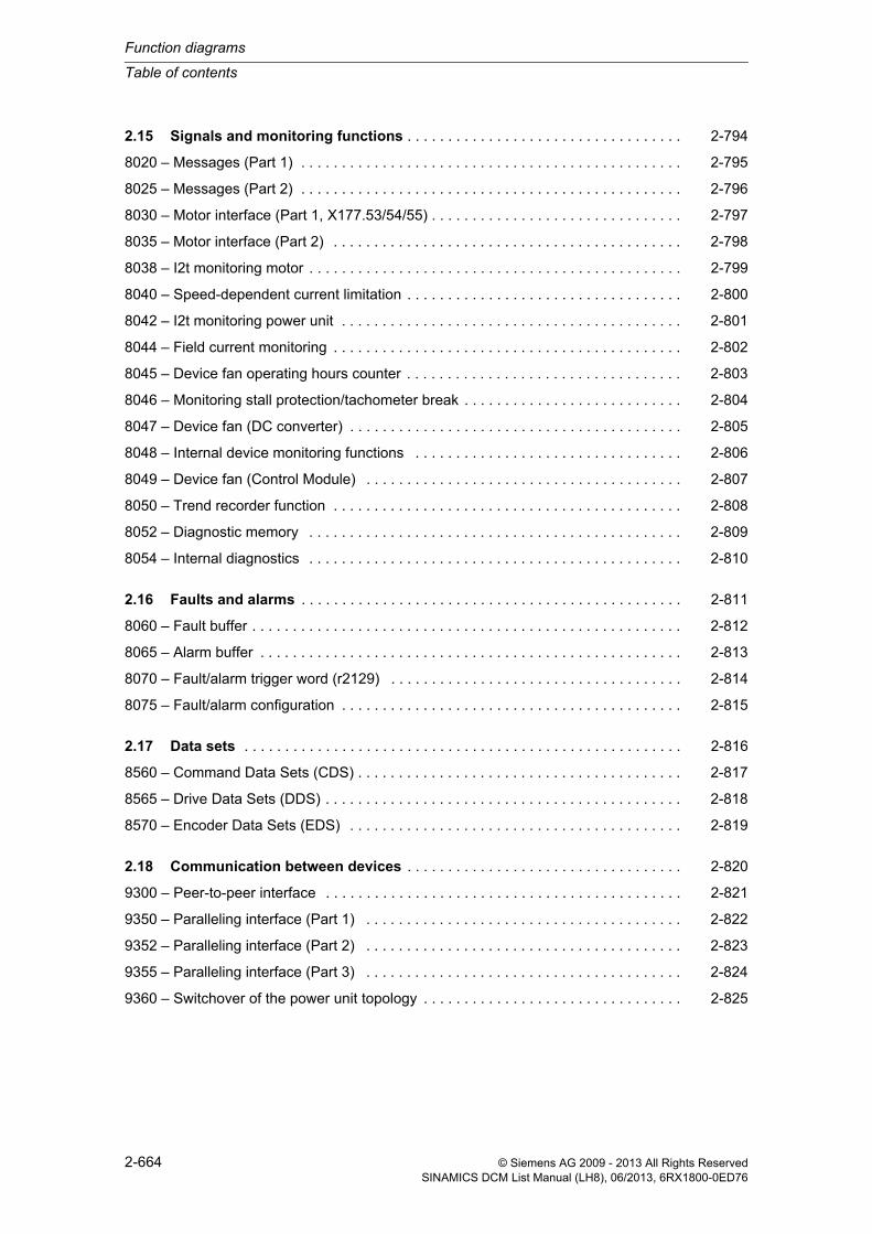
Function diagrams
Table of contents
2-664 © Siemens AG 2009 - 2013 All Rights ReservedSINAMICS DCM List Manual (LH8), 06/2013, 6RX1800-0ED76
2.15 Signals and monitoring functions . . . . . . . . . . . . . . . . . . . . . . . . . . . . . . . . . . 2-794
8020 – Messages (Part 1) . . . . . . . . . . . . . . . . . . . . . . . . . . . . . . . . . . . . . . . . . . . . . . . 2-795
8025 – Messages (Part 2) . . . . . . . . . . . . . . . . . . . . . . . . . . . . . . . . . . . . . . . . . . . . . . . 2-796
8030 – Motor interface (Part 1, X177.53/54/55) . . . . . . . . . . . . . . . . . . . . . . . . . . . . . . . 2-797
8035 – Motor interface (Part 2) . . . . . . . . . . . . . . . . . . . . . . . . . . . . . . . . . . . . . . . . . . . 2-798
8038 – I2t monitoring motor . . . . . . . . . . . . . . . . . . . . . . . . . . . . . . . . . . . . . . . . . . . . . . 2-799
8040 – Speed-dependent current limitation . . . . . . . . . . . . . . . . . . . . . . . . . . . . . . . . . . 2-800
8042 – I2t monitoring power unit . . . . . . . . . . . . . . . . . . . . . . . . . . . . . . . . . . . . . . . . . . 2-801
8044 – Field current monitoring . . . . . . . . . . . . . . . . . . . . . . . . . . . . . . . . . . . . . . . . . . . 2-802
8045 – Device fan operating hours counter . . . . . . . . . . . . . . . . . . . . . . . . . . . . . . . . . . 2-803
8046 – Monitoring stall protection/tachometer break . . . . . . . . . . . . . . . . . . . . . . . . . . . 2-804
8047 – Device fan (DC converter) . . . . . . . . . . . . . . . . . . . . . . . . . . . . . . . . . . . . . . . . . 2-805
8048 – Internal device monitoring functions . . . . . . . . . . . . . . . . . . . . . . . . . . . . . . . . . 2-806
8049 – Device fan (Control Module) . . . . . . . . . . . . . . . . . . . . . . . . . . . . . . . . . . . . . . . 2-807
8050 – Trend recorder function . . . . . . . . . . . . . . . . . . . . . . . . . . . . . . . . . . . . . . . . . . . 2-808
8052 – Diagnostic memory . . . . . . . . . . . . . . . . . . . . . . . . . . . . . . . . . . . . . . . . . . . . . . 2-809
8054 – Internal diagnostics . . . . . . . . . . . . . . . . . . . . . . . . . . . . . . . . . . . . . . . . . . . . . . 2-810
2.16 Faults and alarms . . . . . . . . . . . . . . . . . . . . . . . . . . . . . . . . . . . . . . . . . . . . . . . 2-811
8060 – Fault buffer . . . . . . . . . . . . . . . . . . . . . . . . . . . . . . . . . . . . . . . . . . . . . . . . . . . . . 2-812
8065 – Alarm buffer . . . . . . . . . . . . . . . . . . . . . . . . . . . . . . . . . . . . . . . . . . . . . . . . . . . . 2-813
8070 – Fault/alarm trigger word (r2129) . . . . . . . . . . . . . . . . . . . . . . . . . . . . . . . . . . . . 2-814
8075 – Fault/alarm configuration . . . . . . . . . . . . . . . . . . . . . . . . . . . . . . . . . . . . . . . . . . 2-815
2.17 Data sets . . . . . . . . . . . . . . . . . . . . . . . . . . . . . . . . . . . . . . . . . . . . . . . . . . . . . . 2-816
8560 – Command Data Sets (CDS) . . . . . . . . . . . . . . . . . . . . . . . . . . . . . . . . . . . . . . . . 2-817
8565 – Drive Data Sets (DDS) . . . . . . . . . . . . . . . . . . . . . . . . . . . . . . . . . . . . . . . . . . . . 2-818
8570 – Encoder Data Sets (EDS) . . . . . . . . . . . . . . . . . . . . . . . . . . . . . . . . . . . . . . . . . 2-819
2.18 Communication between devices . . . . . . . . . . . . . . . . . . . . . . . . . . . . . . . . . . 2-820
9300 – Peer-to-peer interface . . . . . . . . . . . . . . . . . . . . . . . . . . . . . . . . . . . . . . . . . . . . 2-821
9350 – Paralleling interface (Part 1) . . . . . . . . . . . . . . . . . . . . . . . . . . . . . . . . . . . . . . . 2-822
9352 – Paralleling interface (Part 2) . . . . . . . . . . . . . . . . . . . . . . . . . . . . . . . . . . . . . . . 2-823
9355 – Paralleling interface (Part 3) . . . . . . . . . . . . . . . . . . . . . . . . . . . . . . . . . . . . . . . 2-824
9360 – Switchover of the power unit topology . . . . . . . . . . . . . . . . . . . . . . . . . . . . . . . . 2-825

Table of contents
Function diagrams
2-665© Siemens AG 2009 - 2013 All Rights ReservedSINAMICS DCM List Manual (LH8), 06/2013, 6RX1800-0ED76
2.19 Terminal Module 15 for SINAMICS (TM15DI/DO) . . . . . . . . . . . . . . . . . . . . . . 2-826
9400 – Digital inputs/outputs, bidirectional (DI/DO 0 ... DI/DO 7) . . . . . . . . . . . . . . . . . 2-827
9401 – Digital inputs/outputs, bidirectional (DI/DO 8 ... DI/DO 15) . . . . . . . . . . . . . . . . 2-828
9402 – Digital inputs/outputs, bidirectional (DI/DO 16 ... DI/DO 23) . . . . . . . . . . . . . . . 2-829
2.20 Terminal Module 31 (TM31) . . . . . . . . . . . . . . . . . . . . . . . . . . . . . . . . . . . . . . . 2-830
9550 – Digital inputs, isolated (DI 0 ... DI 3) . . . . . . . . . . . . . . . . . . . . . . . . . . . . . . . . . 2-831
9552 – Digital inputs, isolated (DI 4 ... DI 7) . . . . . . . . . . . . . . . . . . . . . . . . . . . . . . . . . 2-832
9556 – Digital relay outputs, isolated (DO 0 ... DO 1) . . . . . . . . . . . . . . . . . . . . . . . . . . 2-833
9560 – Digital inputs/outputs, bidirectional (DI/DO 8 ... DI/DO 9) . . . . . . . . . . . . . . . . . 2-834
9562 – Digital inputs/outputs, bidirectional (DI/DO 10 ... DI/DO 11) . . . . . . . . . . . . . . . 2-835
9566 – Analog input 0 (AI 0) . . . . . . . . . . . . . . . . . . . . . . . . . . . . . . . . . . . . . . . . . . . . . 2-836
9568 – Analog input 1 (AI 1) . . . . . . . . . . . . . . . . . . . . . . . . . . . . . . . . . . . . . . . . . . . . . 2-837
9572 – Analog outputs (AO 0 ... AO 1) . . . . . . . . . . . . . . . . . . . . . . . . . . . . . . . . . . . . . 2-838
9576 – Temperature evaluation KTY/PTC . . . . . . . . . . . . . . . . . . . . . . . . . . . . . . . . . . . 2-839
9577 – Sensor monitoring KTY/PTC . . . . . . . . . . . . . . . . . . . . . . . . . . . . . . . . . . . . . . . 2-840
2.21 Terminal Module 150 (TM150) . . . . . . . . . . . . . . . . . . . . . . . . . . . . . . . . . . . . . 2-841
9625 – Temperature evaluation structure (channels 0 ... 11) . . . . . . . . . . . . . . . . . . . . 2-842
9626 – Temperature evaluation 1x2, 3, 4-wire (channels 0 ... 5) . . . . . . . . . . . . . . . . . . 2-843
9627 – Temperature evaluation 2x2-wire (channels 0 ... 11) . . . . . . . . . . . . . . . . . . . . . 2-844
2.22 Basic Operator Panel 20 (BOP20) . . . . . . . . . . . . . . . . . . . . . . . . . . . . . . . . . . 2-845
9912 – Control word interconnection . . . . . . . . . . . . . . . . . . . . . . . . . . . . . . . . . . . . . . . 2-846

Function diagrams
Explanation of the function diagrams
2-666 © Siemens AG 2009 - 2013 All Rights ReservedSINAMICS DCM List Manual (LH8), 06/2013, 6RX1800-0ED76
2.2 Explanation of the function diagrams
Function diagrams
1020 – Explanation of the symbols (part 1) 2-667
1021 – Explanation of the symbols (part 2) 2-668
1022 – Explanation of the symbols (part 3) 2-669
1030 – Handling BICO technology 2-670
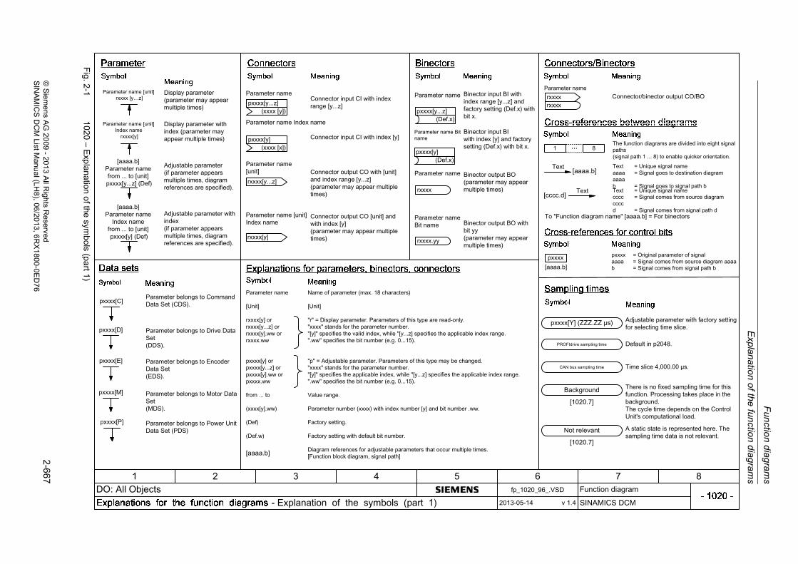
Expla
nation
of the
functio
n d
iagra
ms
Fun
ction
diag
ram
s
2-6
67©
Siem
ens AG
2009
-20
13 All R
ights Reserved
SIN
AM
ICS
DC
M ListM
anual (LH
8), 06/2013, 6RX
1800-0E
D7
6
Fig. 2
-1102
0 – Exp
lanation of the
symbols (pa
rt1)
...
(Def.x)pxxxx[y...z]
(Def.x)
1 8

Fu
nction d
iagram
s
Expla
natio
n of th
e fu
nction dia
gram
s
2-6
68©
Siem
ens AG
2009-
2013 All R
ights Reserved
SIN
AM
ICS
DC
M ListM
anual (LH8), 06/2013
, 6RX
1800-0ED
76
Fig. 2
-2102
1 – Exp
lanation of the
symbols (pa
rt2)
0
1
0
1
ddt
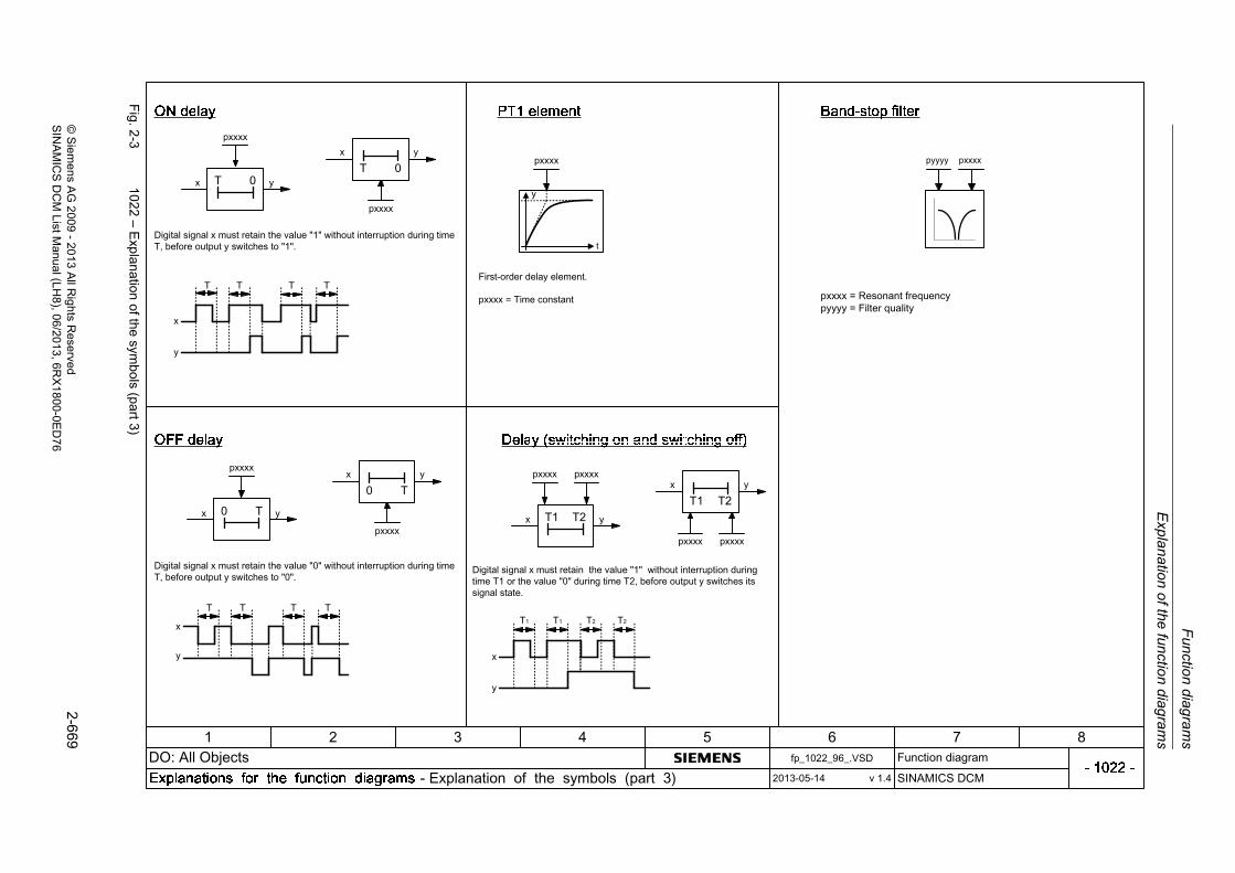
Expla
nation
of the
functio
n d
iagra
ms
Fun
ction
diag
ram
s
2-6
69©
Siem
ens AG
2009
-20
13 All R
ights Reserved
SIN
AM
ICS
DC
M ListM
anual (LH
8), 06/2013, 6RX
1800-0E
D7
6
Fig. 2
-3102
2 – Exp
lanation of the
symbols (pa
rt3)
pyyyy pxxxx

Fu
nction d
iagram
s
Expla
natio
n of th
e fu
nction dia
gram
s
2-6
70©
Siem
ens AG
2009-
2013 All R
ights Reserved
SIN
AM
ICS
DC
M ListM
anual (LH8), 06/2013
, 6RX
1800-0ED
76
Fig. 2
-4103
0 – Hand
ling B
ICO
technolog
y
722.0
1050

Overviews
Function diagrams
2-671© Siemens AG 2009 - 2013 All Rights ReservedSINAMICS DCM List Manual (LH8), 06/2013, 6RX1800-0ED76
2.3 Overviews
Function diagrams
1520 – PROFIdrive 2-672
1580 – Encoder evaluations (position, speed) 2-673
1720 – Closed-loop control 2-674
1721 – Activation/deactivation of closed-loop control functions 2-675
1722 – CUD left, CUD right 2-676
1781 – Terminal Module 15 for SINAMICS (TM15DI/DO) 2-677
1840 – Terminal Module 31 (TM31) 2-678

Fu
nction d
iagram
s
Ove
rview
s
2-6
72©
Siem
ens AG
2009-
2013 All R
ights Reserved
SIN
AM
ICS
DC
M ListM
anual (LH8), 06/2013
, 6RX
1800-0ED
76
Fig. 2
-5152
0 – PR
OF
Idrive
1 2 3 4 5 6 7 8

Ove
rviews
Fun
ction
diag
ram
s
2-6
73©
Siem
ens AG
2009
-20
13 All R
ights Reserved
SIN
AM
ICS
DC
M ListM
anual (LH
8), 06/2013, 6RX
1800-0E
D7
6
Fig. 2
-6158
0 – En
coder evaluatio
ns (position, speed
)
v 1.4

Fu
nction d
iagram
s
Ove
rview
s
2-6
74©
Siem
ens AG
2009-
2013 All R
ights Reserved
SIN
AM
ICS
DC
M ListM
anual (LH8), 06/2013
, 6RX
1800-0ED
76
Fig. 2
-7172
0 – Closed
-loop co
ntrol
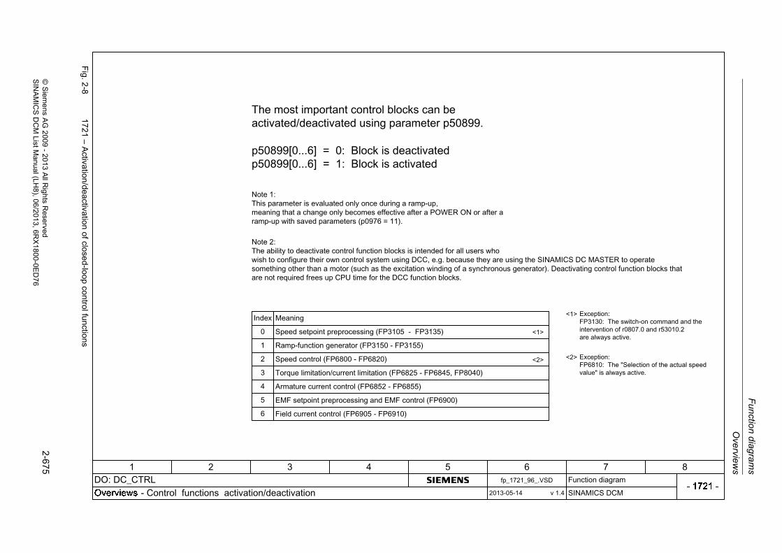
Ove
rviews
Fun
ction
diag
ram
s
2-6
75©
Siem
ens AG
2009
-20
13 All R
ights Reserved
SIN
AM
ICS
DC
M ListM
anual (LH
8), 06/2013, 6RX
1800-0E
D7
6
Fig. 2
-8172
1 – Activatio
n/deactivation of clo
sed-loo
p control functions
<1>
<2>
<1>
<2>

Fu
nction d
iagram
s
Ove
rview
s
2-6
76©
Siem
ens AG
2009-
2013 All R
ights Reserved
SIN
AM
ICS
DC
M ListM
anual (LH8), 06/2013
, 6RX
1800-0ED
76
Fig. 2
-9172
2 – CU
D left, C
UD
right
[9350]

Ove
rviews
Fun
ction
diag
ram
s
2-6
77©
Siem
ens AG
2009
-20
13 All R
ights Reserved
SIN
AM
ICS
DC
M ListM
anual (LH
8), 06/2013, 6RX
1800-0E
D7
6
Fig. 2
-10
1781 – T
ermin
al Module 15 fo
r SIN
AM
ICS
(TM
15D
I/DO
)

Fu
nction d
iagram
s
Ove
rview
s
2-6
78©
Siem
ens AG
2009-
2013 All R
ights Reserved
SIN
AM
ICS
DC
M ListM
anual (LH8), 06/2013
, 6RX
1800-0ED
76
Fig. 2
-11
1840 – T
ermin
al Module 31 (T
M31
)

CUD input/output terminals
Function diagrams
2-679© Siemens AG 2009 - 2013 All Rights ReservedSINAMICS DCM List Manual (LH8), 06/2013, 6RX1800-0ED76
2.4 CUD input/output terminals
Function diagrams
2050 – Digital inputs (DI 0 ... DI 3) 2-680
2055 – Digital outputs (DO 0 ... DO 3) 2-681
2060 – Digital inputs/outputs, bidirectional (DI/DO 4 ... DI/DO 5) 2-682
2065 – Digital inputs/outputs, bidirectional (DI/DO 6 ... DI/DO 7) 2-683
2070 – E stop (emergency stop), relay output main contactor 2-684
2075 – Analog inputs (AI 0 and XT1.103/104) 2-685
2080 – Analog inputs (AI 1 ... AI 2) 2-686
2085 – Analog inputs (AI 3 ... AI 4) 2-687
2090 – Analog inputs (AI 5 ... AI 6) 2-688
2095 – Analog outputs (AO 0 ... AO 1) 2-689

Fu
nction d
iagram
s
CU
D input/output term
inals
2-6
80©
Siem
ens AG
2009-
2013 All R
ights Reserved
SIN
AM
ICS
DC
M ListM
anual (LH8), 06/2013
, 6RX
1800-0ED
76
Fig. 2
-12
2050 – D
igital inputs (DI0
...DI3)
CUD DI sim selp50765.0 (0)CUD DI simul setp
p50766.0 (0)
CUD DI sim selp50765.1 (0)CUD DI simul setp
p50766.1 (0)
CUD DI sim selp50765.2 (0)CUD DI simul setp
p50766.2 (0)
CUD DI sim selp50765.3 (0)CUD DI simul setp
p50766.3 (0)
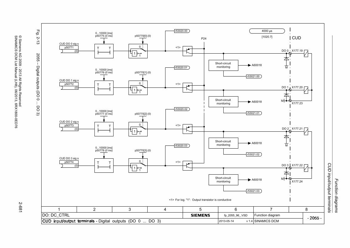
CU
D in
put/ou
tpu
t termin
als
Fun
ction
diag
ram
s
2-6
81©
Siem
ens AG
2009
-20
13 All R
ights Reserved
SIN
AM
ICS
DC
M ListM
anual (LH
8), 06/2013, 6RX
1800-0E
D7
6
Fig. 2
-13
2055 – D
igital outputs (D
O0
...DO
3)
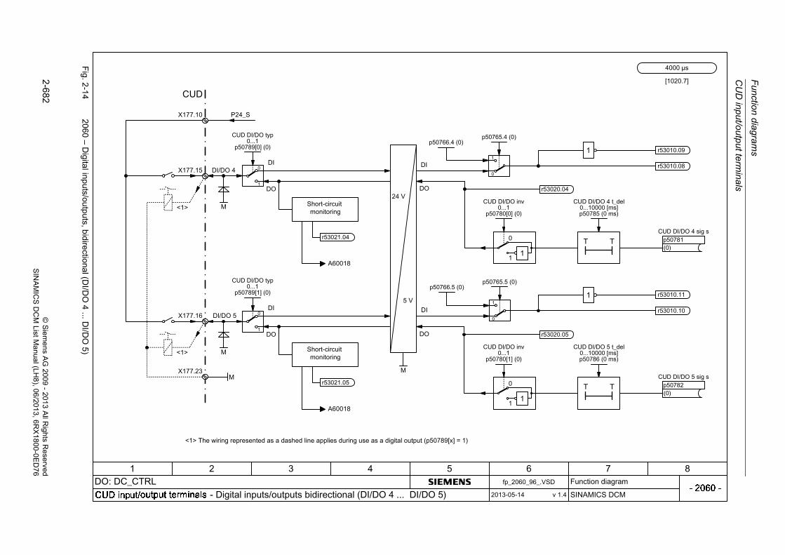
Fu
nction d
iagram
s
CU
D input/output term
inals
2-6
82©
Siem
ens AG
2009-
2013 All R
ights Reserved
SIN
AM
ICS
DC
M ListM
anual (LH8), 06/2013
, 6RX
1800-0ED
76
Fig. 2
-14
2060 – D
igital inputs/outputs, bidirectio
nal (DI/D
O4
...DI/D
O5)
p50765.4 (0)p50766.4 (0)
p50765.5 (0)p50766.5 (0)

CU
D in
put/ou
tpu
t termin
als
Fun
ction
diag
ram
s
2-6
83©
Siem
ens AG
2009
-20
13 All R
ights Reserved
SIN
AM
ICS
DC
M ListM
anual (LH
8), 06/2013, 6RX
1800-0E
D7
6
Fig. 2
-15
2065 – D
igital inputs/outputs, bidirectio
nal (DI/D
O6
...DI/D
O7)
p50765.6 (0)p50766.6 (0)
p50765.7 (0)p50766.7 (0)

Fu
nction d
iagram
s
CU
D input/output term
inals
2-6
84©
Siem
ens AG
2009-
2013 All R
ights Reserved
SIN
AM
ICS
DC
M ListM
anual (LH8), 06/2013
, 6RX
1800-0ED
76
Fig. 2
-16
2070 – E
stop (emerge
ncy stop), relay outpu
t main
conta
ctor

CU
D in
put/ou
tpu
t termin
als
Fun
ction
diag
ram
s
2-6
85©
Siem
ens AG
2009
-20
13 All R
ights Reserved
SIN
AM
ICS
DC
M ListM
anual (LH
8), 06/2013, 6RX
1800-0E
D7
6
Fig. 2
-17
2075 – A
nalo
g inputs (A
I0and
XT
1.103/10
4)
CUD AI 0 sim selp50709 (0)
CUD AI 0 sim setp-130.0...130.0 [%]
p50707 (0.0)
AI m_actV sim selp50749 (0)
AI m_actV sim setp-130.0...130.0 [%]
p50747 (0.0)
±20mA±10V

Fu
nction d
iagram
s
CU
D input/output term
inals
2-6
86©
Siem
ens AG
2009-
2013 All R
ights Reserved
SIN
AM
ICS
DC
M ListM
anual (LH8), 06/2013
, 6RX
1800-0ED
76
Fig. 2
-18
2080 – A
nalo
g inputs (A
I1...A
I2)
CUD AI 1 sim selp50719 (0)
CUD AI 1 sim setp-130.0...130.0 [%]
p50717 (0.0)
CUD AI 2 sim selp50729 (0)
CUD AI 2 sim setp-130.0...130.0 [%]
p50727 (0.0)
±20mA±10V
±10V

CU
D in
put/ou
tpu
t termin
als
Fun
ction
diag
ram
s
2-6
87©
Siem
ens AG
2009
-20
13 All R
ights Reserved
SIN
AM
ICS
DC
M ListM
anual (LH
8), 06/2013, 6RX
1800-0E
D7
6
Fig. 2
-19
2085 – A
nalo
g inputs (A
I3...A
I4)
Fast AI sim selp50739[0] (0)
Fast AI sim setp-130.0...130.0 [%]p50737[0] (0.0)
Fast AI sim selp50739[1] (0)
Fast AI sim setp-130.0...130.0 [%]
p50737[1] (0.0)
±10V
±10V

Fu
nction d
iagram
s
CU
D input/output term
inals
2-6
88©
Siem
ens AG
2009-
2013 All R
ights Reserved
SIN
AM
ICS
DC
M ListM
anual (LH8), 06/2013
, 6RX
1800-0ED
76
Fig. 2
-20
2090 – A
nalo
g inputs (A
I5...A
I6)
Fast AI sim selp50739[3] (0)
Fast AI sim setp-130.0...130.0 [%]p50737[3] (0.0)
Fast AI sim selp50739[2] (0)
Fast AI sim setp-130.0...130.0 [%]p50737[2] (0.0)
±10V
±10V

CU
D in
put/ou
tpu
t termin
als
Fun
ction
diag
ram
s
2-6
89©
Siem
ens AG
2009
-20
13 All R
ights Reserved
SIN
AM
ICS
DC
M ListM
anual (LH
8), 06/2013, 6RX
1800-0E
D7
6
Fig. 2
-21
2095 – A
nalo
g outputs (AO
0...A
O1)

Function diagrams
PROFIdrive
2-690 © Siemens AG 2009 - 2013 All Rights ReservedSINAMICS DCM List Manual (LH8), 06/2013, 6RX1800-0ED76
2.5 PROFIdrive
Function diagrams
2410 – PROFIBUS (PB) / PROFINET (PN) / USS, addresses and diagnostics 2-691
2420 – Telegrams and process data (PZD) 2-692
2425 – STW1_BM control word metal industry interconnection 2-693
2426 – STW2_BM control word metal industry interconnection 2-694
2428 – ZSW1_BM status word metal industry interconnection 2-695
2429 – ZSW2_BM status word metal industry interconnection 2-696
2440 – PZD receive signals interconnection 2-697
2442 – STW1 control word interconnection 2-698
2444 – STW2 control word interconnection 2-699
2450 – PZD send signals interconnection 2-700
2452 – ZSW1 status word interconnection 2-701
2454 – ZSW2 status word interconnection 2-702
2460 – IF1 receive telegram, free interconnection via BICO (p0922 = 999) 2-703
2470 – IF1 send telegram, free interconnection via BICO (p0922 = 999) 2-704
2472 – IF1 status words, free interconnection 2-705
2481 – IF1 receive telegram, free interconnection via BICO (p0922 = 999) 2-706
2483 – IF1 send telegram, free interconnection via BICO (p0922 = 999) 2-707
2485 – IF2 receive telegram, free interconnection via BICO (p0922 = 999) 2-708
2487 – IF2 send telegram, free interconnection via BICO (p0922 = 999) 2-709
2489 – IF2 status words, free interconnection 2-710
2495 – CU_STW1 control word 1, Control Unit interconnection 2-711
2496 – CU_ZSW1 status word 1, Control Unit interconnection 2-712
2497 – A_DIGITAL interconnection 2-713
2498 – E_DIGITAL interconnection 2-714

PR
OF
Idrive
Fun
ction
diag
ram
s
2-6
91©
Siem
ens AG
2009
-20
13 All R
ights Reserved
SIN
AM
ICS
DC
M ListM
anual (LH
8), 06/2013, 6RX
1800-0E
D7
6
Fig. 2
-22
2410 – P
RO
FIB
US
(PB
) / PR
OF
INE
T (P
N) / U
SS
, addresse
s and dia
gnostics

Fu
nction d
iagram
s
PR
OF
Idrive
2-6
92©
Siem
ens AG
2009-
2013 All R
ights Reserved
SIN
AM
ICS
DC
M ListM
anual (LH8), 06/2013
, 6RX
1800-0ED
76
Fig. 2
-23
2420 – T
elegrams and
process d
ata (P
ZD
)
IF1 PZD telegrp00922 (999)

PR
OF
Idrive
Fun
ction
diag
ram
s
2-6
93©
Siem
ens AG
2009
-20
13 All R
ights Reserved
SIN
AM
ICS
DC
M ListM
anual (LH
8), 06/2013, 6RX
1800-0E
D7
6
Fig. 2
-24
2425 – S
TW
1_B
M con
trol w
ord meta
l industry intercon
nection

Fu
nction d
iagram
s
PR
OF
Idrive
2-6
94©
Siem
ens AG
2009-
2013 All R
ights Reserved
SIN
AM
ICS
DC
M ListM
anual (LH8), 06/2013
, 6RX
1800-0ED
76
Fig. 2
-25
2426 – S
TW
2_B
M con
trol w
ord meta
l industry intercon
nection
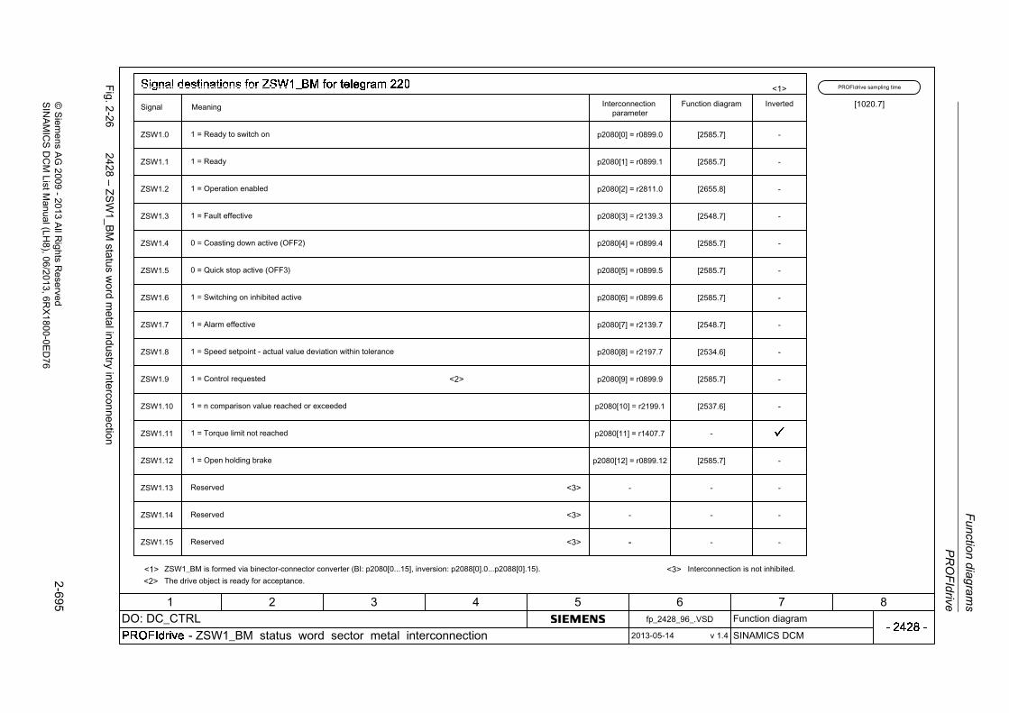
PR
OF
Idrive
Fun
ction
diag
ram
s
2-6
95©
Siem
ens AG
2009
-20
13 All R
ights Reserved
SIN
AM
ICS
DC
M ListM
anual (LH
8), 06/2013, 6RX
1800-0E
D7
6
Fig. 2
-26
2428 – Z
SW
1_B
M status w
ord metal ind
ustry interconnection

Fu
nction d
iagram
s
PR
OF
Idrive
2-6
96©
Siem
ens AG
2009-
2013 All R
ights Reserved
SIN
AM
ICS
DC
M ListM
anual (LH8), 06/2013
, 6RX
1800-0ED
76
Fig. 2
-27
2429 – Z
SW
2_B
M status w
ord metal ind
ustry interconnection

PR
OF
Idrive
Fun
ction
diag
ram
s
2-6
97©
Siem
ens AG
2009
-20
13 All R
ights Reserved
SIN
AM
ICS
DC
M ListM
anual (LH
8), 06/2013, 6RX
1800-0E
D7
6
Fig. 2
-28
2440 – P
ZD
receive sig
nals interco
nnection
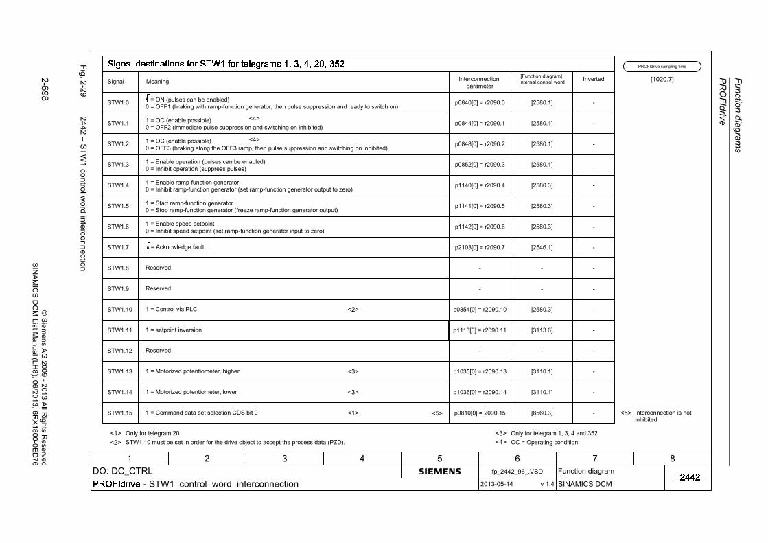
Fu
nction d
iagram
s
PR
OF
Idrive
2-6
98©
Siem
ens AG
2009-
2013 All R
ights Reserved
SIN
AM
ICS
DC
M ListM
anual (LH8), 06/2013
, 6RX
1800-0ED
76
Fig. 2
-29
2442 – S
TW
1 co
ntrol w
ord interconnection

PR
OF
Idrive
Fun
ction
diag
ram
s
2-6
99©
Siem
ens AG
2009
-20
13 All R
ights Reserved
SIN
AM
ICS
DC
M ListM
anual (LH
8), 06/2013, 6RX
1800-0E
D7
6
Fig. 2
-30
2444 – S
TW
2 co
ntrol w
ord interconnection

Fu
nction d
iagram
s
PR
OF
Idrive
2-7
00©
Siem
ens AG
2009-
2013 All R
ights Reserved
SIN
AM
ICS
DC
M ListM
anual (LH8), 06/2013
, 6RX
1800-0ED
76
Fig. 2
-31
2450 – P
ZD
send sig
nals interco
nnection

PR
OF
Idrive
Fun
ction
diag
ram
s
2-7
01©
Siem
ens AG
2009
-20
13 All R
ights Reserved
SIN
AM
ICS
DC
M ListM
anual (LH
8), 06/2013, 6RX
1800-0E
D7
6
Fig. 2
-32
2452 – Z
SW
1 status w
ord interconnection
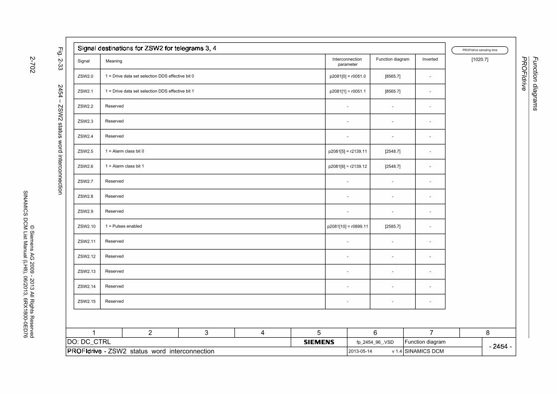
Fu
nction d
iagram
s
PR
OF
Idrive
2-7
02©
Siem
ens AG
2009-
2013 All R
ights Reserved
SIN
AM
ICS
DC
M ListM
anual (LH8), 06/2013
, 6RX
1800-0ED
76
Fig. 2
-33
2454 – Z
SW
2 status w
ord interconnection

PR
OF
Idrive
Fun
ction
diag
ram
s
2-7
03©
Siem
ens AG
2009
-20
13 All R
ights Reserved
SIN
AM
ICS
DC
M ListM
anual (LH
8), 06/2013, 6RX
1800-0E
D7
6
Fig. 2
-34
2460 – IF
1 receive telegram
, free interconnection
via B
ICO
(p0922
=9
99)

Fu
nction d
iagram
s
PR
OF
Idrive
2-7
04©
Siem
ens AG
2009-
2013 All R
ights Reserved
SIN
AM
ICS
DC
M ListM
anual (LH8), 06/2013
, 6RX
1800-0ED
76
Fig. 2
-35
2470 – IF
1 send telegram
, free interconnection
via B
ICO
(p0922
=9
99)

PR
OF
Idrive
Fun
ction
diag
ram
s
2-7
05©
Siem
ens AG
2009
-20
13 All R
ights Reserved
SIN
AM
ICS
DC
M ListM
anual (LH
8), 06/2013, 6RX
1800-0E
D7
6
Fig. 2
-36
2472 – IF
1 status word
s, free interconn
ection

Fu
nction d
iagram
s
PR
OF
Idrive
2-7
06©
Siem
ens AG
2009-
2013 All R
ights Reserved
SIN
AM
ICS
DC
M ListM
anual (LH8), 06/2013
, 6RX
1800-0ED
76
Fig. 2
-37
2481 – IF
1 receive telegram
, free interconnection
via B
ICO
(p0922
=9
99)
1 2 3 4 5 6 7 8

PR
OF
Idrive
Fun
ction
diag
ram
s
2-7
07©
Siem
ens AG
2009
-20
13 All R
ights Reserved
SIN
AM
ICS
DC
M ListM
anual (LH
8), 06/2013, 6RX
1800-0E
D7
6
Fig. 2
-38
2483 – IF
1 send telegram
, free interconnection
via B
ICO
(p0922
=9
99)
1 2 3 4 5 6 7 8
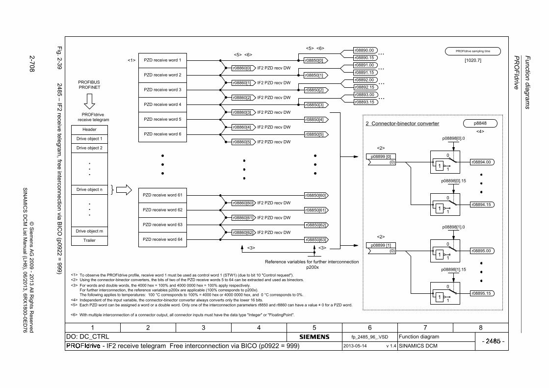
Fu
nction d
iagram
s
PR
OF
Idrive
2-7
08©
Siem
ens AG
2009-
2013 All R
ights Reserved
SIN
AM
ICS
DC
M ListM
anual (LH8), 06/2013
, 6RX
1800-0ED
76
Fig. 2
-39
2485 – IF
2 receive telegram
, free interconnection
via B
ICO
(p0922
=9
99)

PR
OF
Idrive
Fun
ction
diag
ram
s
2-7
09©
Siem
ens AG
2009
-20
13 All R
ights Reserved
SIN
AM
ICS
DC
M ListM
anual (LH
8), 06/2013, 6RX
1800-0E
D7
6
Fig. 2
-40
2487 – IF
2 send telegram
, free interconnection
via B
ICO
(p0922
=9
99)
+

Fu
nction d
iagram
s
PR
OF
Idrive
2-7
10©
Siem
ens AG
2009-
2013 All R
ights Reserved
SIN
AM
ICS
DC
M ListM
anual (LH8), 06/2013
, 6RX
1800-0ED
76
Fig. 2
-41
2489 – IF
2 status word
s, free interconn
ection

PR
OF
Idrive
Fun
ction
diag
ram
s
2-7
11©
Siem
ens AG
2009
-20
13 All R
ights Reserved
SIN
AM
ICS
DC
M ListM
anual (LH
8), 06/2013, 6RX
1800-0E
D7
6
Fig. 2
-42
2495 – C
U_S
TW
1 control wo
rd 1
, Con
trol Unit interconne
ction
1 2 3 4 5 6 7 8
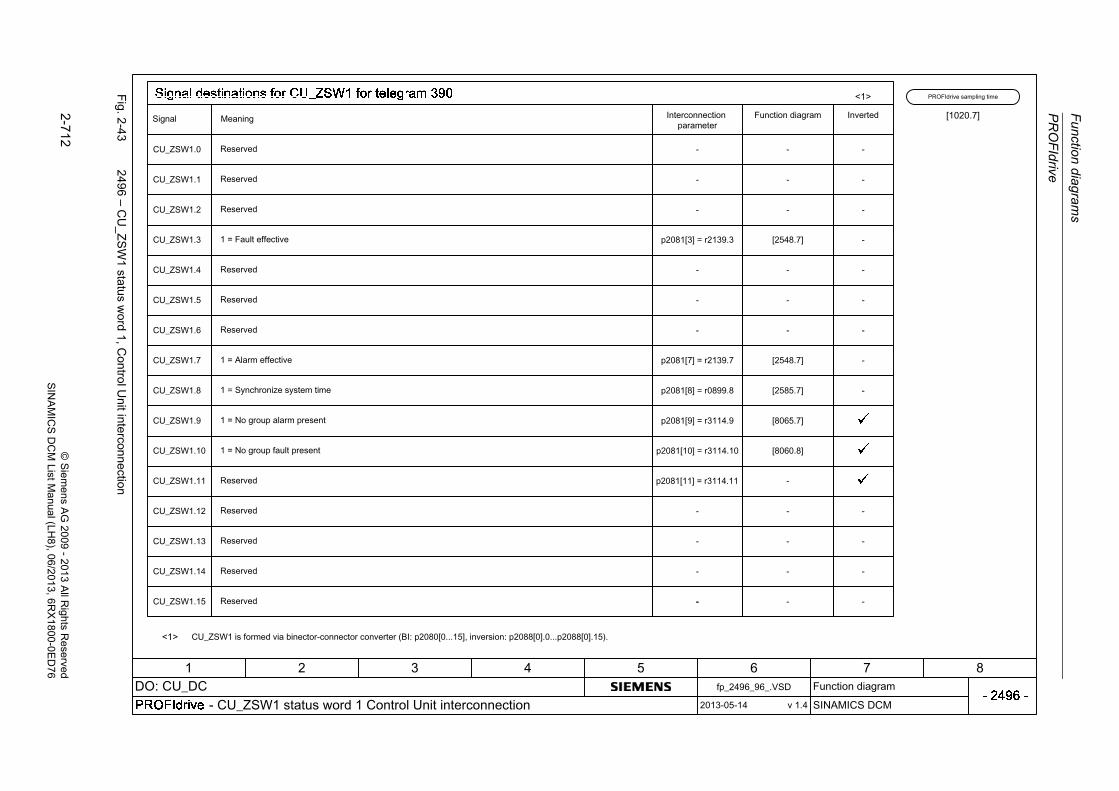
Fu
nction d
iagram
s
PR
OF
Idrive
2-7
12©
Siem
ens AG
2009-
2013 All R
ights Reserved
SIN
AM
ICS
DC
M ListM
anual (LH8), 06/2013
, 6RX
1800-0ED
76
Fig. 2
-43
2496 – C
U_Z
SW
1 statu
s wo
rd 1, C
ontro
l Unit interconn
ection
1 2 3 4 5 6 7 8

PR
OF
Idrive
Fun
ction
diag
ram
s
2-7
13©
Siem
ens AG
2009
-20
13 All R
ights Reserved
SIN
AM
ICS
DC
M ListM
anual (LH
8), 06/2013, 6RX
1800-0E
D7
6
Fig. 2
-44
2497 – A
_D
IGIT
AL in
terco
nnection
1 2 3 4 5 6 7 8

Fu
nction d
iagram
s
PR
OF
Idrive
2-7
14©
Siem
ens AG
2009-
2013 All R
ights Reserved
SIN
AM
ICS
DC
M ListM
anual (LH8), 06/2013
, 6RX
1800-0ED
76
Fig. 2
-45
2498 – E
_D
IGIT
AL in
terco
nnection
1 2 3 4 5 6 7 8

Internal control/status words
Function diagrams
2-715© Siemens AG 2009 - 2013 All Rights ReservedSINAMICS DCM List Manual (LH8), 06/2013, 6RX1800-0ED76
2.6 Internal control/status words
Function diagrams
2534 – Status word, monitoring functions 1 2-716
2537 – Status word, monitoring functions 3 2-717
2546 – Control word faults/alarms 2-718
2548 – Status word faults/alarms 1 and 2 2-719
2580 – Control word sequence control 2-720
2585 – Status word sequence control 2-721

Fu
nction d
iagram
s
Internal control/status w
ords
2-7
16©
Siem
ens AG
2009-
2013 All R
ights Reserved
SIN
AM
ICS
DC
M ListM
anual (LH8), 06/2013
, 6RX
1800-0ED
76
Fig. 2
-46
2534 – S
tatus word, m
onitoring fu
nctions 1

Inte
rnal co
ntrol/sta
tus w
ord
s
Fun
ction
diag
ram
s
2-7
17©
Siem
ens AG
2009
-20
13 All R
ights Reserved
SIN
AM
ICS
DC
M ListM
anual (LH
8), 06/2013, 6RX
1800-0E
D7
6
Fig. 2
-47
2537 – S
tatus word, m
onitoring fu
nctions 3

Fu
nction d
iagram
s
Internal control/status w
ords
2-7
18©
Siem
ens AG
2009-
2013 All R
ights Reserved
SIN
AM
ICS
DC
M ListM
anual (LH8), 06/2013
, 6RX
1800-0ED
76
Fig. 2
-48
2546 – C
ontrol word
faults/alarm
s
1
1
1
1
1
1

Inte
rnal co
ntrol/sta
tus w
ord
s
Fun
ction
diag
ram
s
2-7
19©
Siem
ens AG
2009
-20
13 All R
ights Reserved
SIN
AM
ICS
DC
M ListM
anual (LH
8), 06/2013, 6RX
1800-0E
D7
6
Fig. 2
-49
2548 – S
tatus word faults/ala
rms 1 and
2
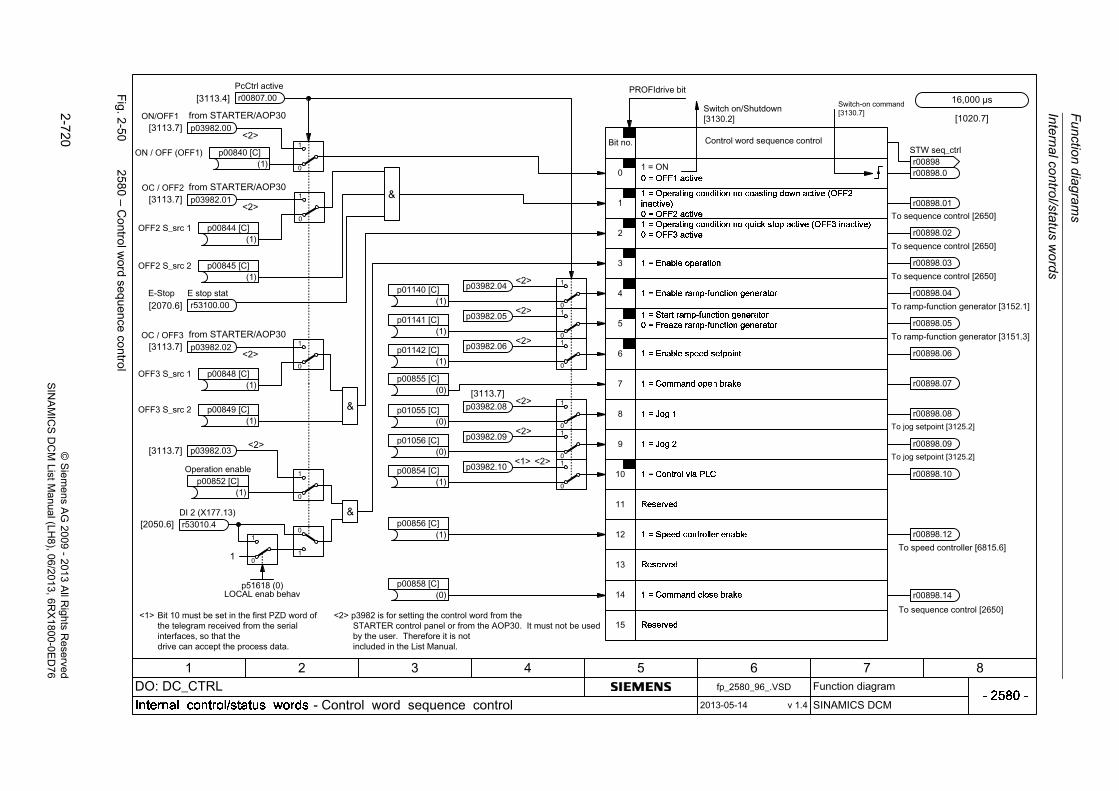
Fu
nction d
iagram
s
Internal control/status w
ords
2-7
20©
Siem
ens AG
2009-
2013 All R
ights Reserved
SIN
AM
ICS
DC
M ListM
anual (LH8), 06/2013
, 6RX
1800-0ED
76
Fig. 2
-50
2580 – C
ontrol word
sequen
ce co
ntrol
r53010.4DI 2 (X177.13)
p51618 (0)LOCAL enab behav
+

Inte
rnal co
ntrol/sta
tus w
ord
s
Fun
ction
diag
ram
s
2-7
21©
Siem
ens AG
2009
-20
13 All R
ights Reserved
SIN
AM
ICS
DC
M ListM
anual (LH
8), 06/2013, 6RX
1800-0E
D7
6
Fig. 2
-51
2585 – S
tatus word seq
uence con
trol

Function diagrams
Sequence control
2-722 © Siemens AG 2009 - 2013 All Rights ReservedSINAMICS DCM List Manual (LH8), 06/2013, 6RX1800-0ED76
2.7 Sequence control
Function diagrams
2650 – Sequencer (Part 1) 2-723
2651 – Sequencer (Part 2) 2-724
2655 – Missing enable signals, logic operations 2-725
2660 – Optimization runs 2-726

Seq
uen
ce co
ntro
l
Fun
ction
diag
ram
s
2-7
23©
Siem
ens AG
2009
-20
13 All R
ights Reserved
SIN
AM
ICS
DC
M ListM
anual (LH
8), 06/2013, 6RX
1800-0E
D7
6
Fig. 2
-52
2650 – S
eque
ncer (Pa
rt1)

Fu
nction d
iagram
s
Se
que
nce control
2-7
24©
Siem
ens AG
2009-
2013 All R
ights Reserved
SIN
AM
ICS
DC
M ListM
anual (LH8), 06/2013
, 6RX
1800-0ED
76
Fig. 2
-53
2651 – S
eque
ncer (Pa
rt2)

Seq
uen
ce co
ntro
l
Fun
ction
diag
ram
s
2-7
25©
Siem
ens AG
2009
-20
13 All R
ights Reserved
SIN
AM
ICS
DC
M ListM
anual (LH
8), 06/2013, 6RX
1800-0E
D7
6
Fig. 2
-54
2655 – M
issing enable
signals, logic o
perations
&
>1_

Fu
nction d
iagram
s
Se
que
nce control
2-7
26©
Siem
ens AG
2009-
2013 All R
ights Reserved
SIN
AM
ICS
DC
M ListM
anual (LH8), 06/2013
, 6RX
1800-0ED
76
Fig. 2
-55
2660 – O
ptimizatio
n runs

Brake control
Function diagrams
2-727© Siemens AG 2009 - 2013 All Rights ReservedSINAMICS DCM List Manual (LH8), 06/2013, 6RX1800-0ED76
2.8 Brake control
Function diagrams
2750 – Brake control 2-728

Fu
nction d
iagram
s
Brake con
trol
2-7
28©
Siem
ens AG
2009-
2013 All R
ights Reserved
SIN
AM
ICS
DC
M ListM
anual (LH8), 06/2013
, 6RX
1800-0ED
76
Fig. 2
-56
2750 – B
rake co
ntrol
+10
2
+

Setpoint channel
Function diagrams
2-729© Siemens AG 2009 - 2013 All Rights ReservedSINAMICS DCM List Manual (LH8), 06/2013, 6RX1800-0ED76
2.9 Setpoint channel
Function diagrams
3100 – Fixed values 2-730
3105 – 4-stage joystick switch 2-731
3110 – Motorized potentiometer 2-732
3113 – AOP30 display and control unit 2-733
3115 – Fixed setpoint 2-734
3120 – Oscillation/square-wave generator 2-735
3125 – Jog setpoint 2-736
3130 – Creep setpoint 2-737
3135 – Setpoint processing 2-738
3150 – Ramp-function generator (Part 1) 2-739
3151 – Ramp-function generator (Part 2) 2-740
3152 – Ramp-function generator (Part 3) 2-741
3155 – Limitation after ramp-function generator 2-742
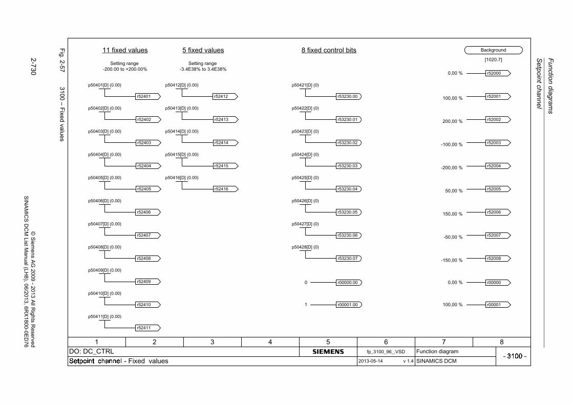
Fu
nction d
iagram
s
Se
tpoin
t chan
nel
2-7
30©
Siem
ens AG
2009-
2013 All R
ights Reserved
SIN
AM
ICS
DC
M ListM
anual (LH8), 06/2013
, 6RX
1800-0ED
76
Fig. 2
-57
3100 – F
ixed va
lues
r00000.00
r00001.00
r00000
r00001

Se
tpoin
t chan
nel
Fun
ction
diag
ram
s
2-7
31©
Siem
ens AG
2009
-20
13 All R
ights Reserved
SIN
AM
ICS
DC
M ListM
anual (LH
8), 06/2013, 6RX
1800-0E
D7
6
Fig. 2
-58
3105 – 4-sta
ge joystick switch

Fu
nction d
iagram
s
Se
tpoin
t chan
nel
2-7
32©
Siem
ens AG
2009-
2013 All R
ights Reserved
SIN
AM
ICS
DC
M ListM
anual (LH8), 06/2013
, 6RX
1800-0ED
76
Fig. 2
-59
3110 – M
oto
rized potentio
mete
r

Se
tpoin
t chan
nel
Fun
ction
diag
ram
s
2-7
33©
Siem
ens AG
2009
-20
13 All R
ights Reserved
SIN
AM
ICS
DC
M ListM
anual (LH
8), 06/2013, 6RX
1800-0E
D7
6
Fig. 2
-60
3113 – A
OP
30 display and co
ntrol unit

Fu
nction d
iagram
s
Se
tpoin
t chan
nel
2-7
34©
Siem
ens AG
2009-
2013 All R
ights Reserved
SIN
AM
ICS
DC
M ListM
anual (LH8), 06/2013
, 6RX
1800-0ED
76
Fig. 2
-61
3115 – F
ixed se
tpoint

Se
tpoin
t chan
nel
Fun
ction
diag
ram
s
2-7
35©
Siem
ens AG
2009
-20
13 All R
ights Reserved
SIN
AM
ICS
DC
M ListM
anual (LH
8), 06/2013, 6RX
1800-0E
D7
6
Fig. 2
-62
3120 – O
scillation/square-w
ave generator
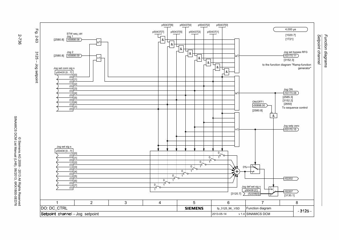
Fu
nction d
iagram
s
Se
tpoin
t chan
nel
2-7
36©
Siem
ens AG
2009-
2013 All R
ights Reserved
SIN
AM
ICS
DC
M ListM
anual (LH8), 06/2013
, 6RX
1800-0ED
76
Fig. 2
-63
3125 – Jo
g setpoin
t

Se
tpoin
t chan
nel
Fun
ction
diag
ram
s
2-7
37©
Siem
ens AG
2009
-20
13 All R
ights Reserved
SIN
AM
ICS
DC
M ListM
anual (LH
8), 06/2013, 6RX
1800-0E
D7
6
Fig. 2
-64
3130 – C
reep setpoint
r53010.02DI 1 (X177.12)

Fu
nction d
iagram
s
Se
tpoin
t chan
nel
2-7
38©
Siem
ens AG
2009-
2013 All R
ights Reserved
SIN
AM
ICS
DC
M ListM
anual (LH8), 06/2013
, 6RX
1800-0ED
76
Fig. 2
-65
3135 – S
etp
oint processin
g
+
p02000

Se
tpoin
t chan
nel
Fun
ction
diag
ram
s
2-7
39©
Siem
ens AG
2009
-20
13 All R
ights Reserved
SIN
AM
ICS
DC
M ListM
anual (LH
8), 06/2013, 6RX
1800-0E
D7
6
Fig. 2
-66
3150 – R
amp-function
generator (P
art1)
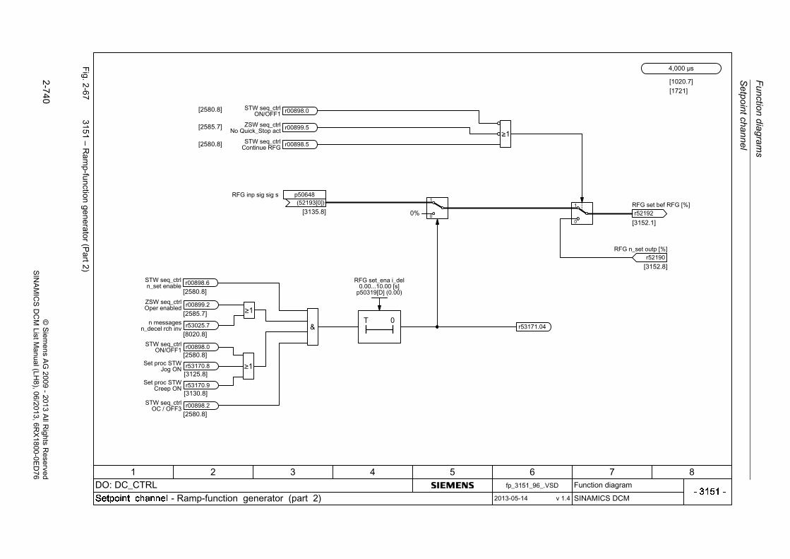
Fu
nction d
iagram
s
Se
tpoin
t chan
nel
2-7
40©
Siem
ens AG
2009-
2013 All R
ights Reserved
SIN
AM
ICS
DC
M ListM
anual (LH8), 06/2013
, 6RX
1800-0ED
76
Fig. 2
-67
3151 – R
amp-function
generator (P
art2)
>1_
>1_

Se
tpoin
t chan
nel
Fun
ction
diag
ram
s
2-7
41©
Siem
ens AG
2009
-20
13 All R
ights Reserved
SIN
AM
ICS
DC
M ListM
anual (LH
8), 06/2013, 6RX
1800-0E
D7
6
Fig. 2
-68
3152 – R
amp-function
generator (P
art3)
p00408
p00418
+
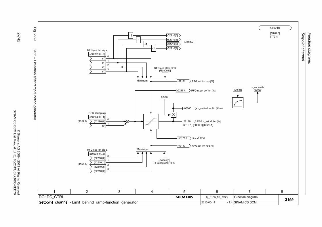
Fu
nction d
iagram
s
Se
tpoin
t chan
nel
2-7
42©
Siem
ens AG
2009-
2013 All R
ights Reserved
SIN
AM
ICS
DC
M ListM
anual (LH8), 06/2013
, 6RX
1800-0ED
76
Fig. 2
-69
3155 – Lim
itation after ra
mp-fu
nction generator
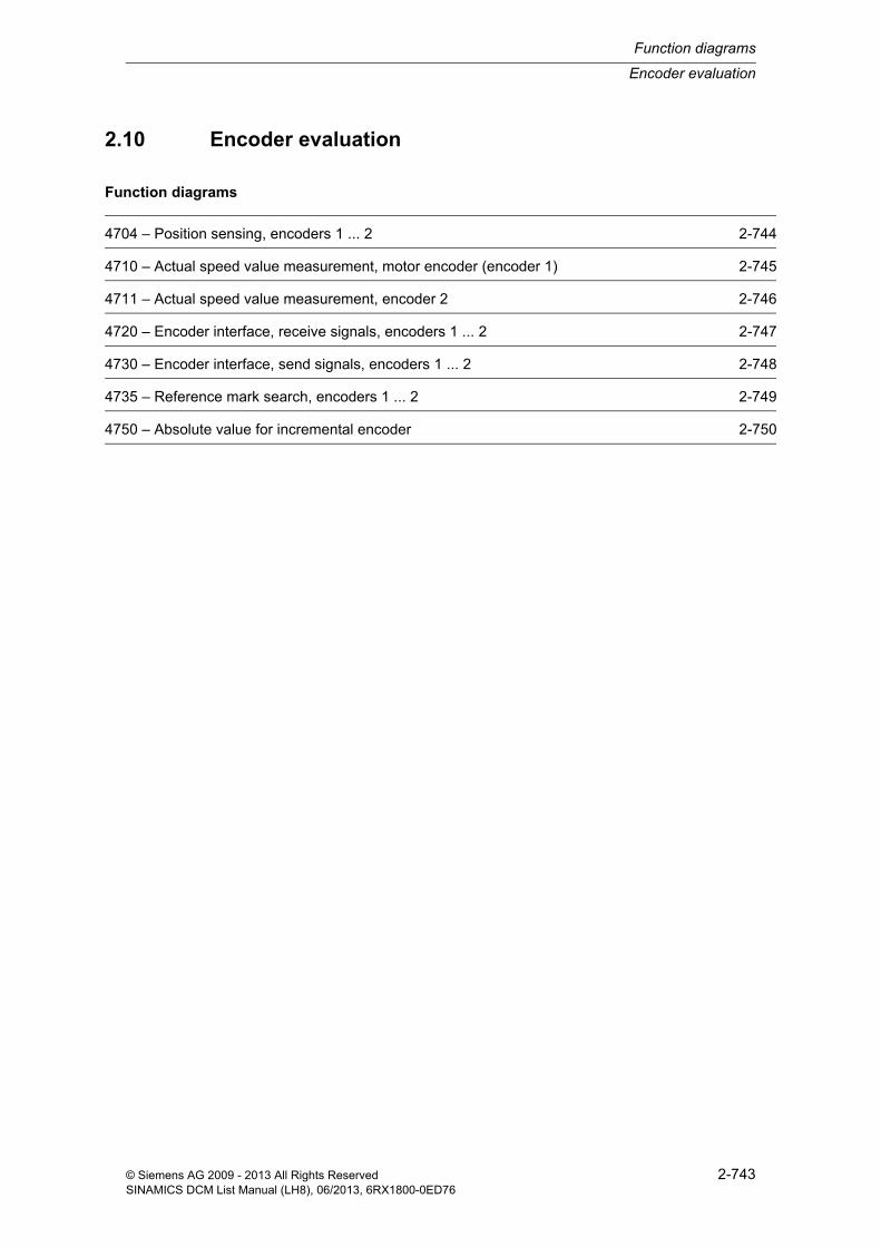
Encoder evaluation
Function diagrams
2-743© Siemens AG 2009 - 2013 All Rights ReservedSINAMICS DCM List Manual (LH8), 06/2013, 6RX1800-0ED76
2.10 Encoder evaluation
Function diagrams
4704 – Position sensing, encoders 1 ... 2 2-744
4710 – Actual speed value measurement, motor encoder (encoder 1) 2-745
4711 – Actual speed value measurement, encoder 2 2-746
4720 – Encoder interface, receive signals, encoders 1 ... 2 2-747
4730 – Encoder interface, send signals, encoders 1 ... 2 2-748
4735 – Reference mark search, encoders 1 ... 2 2-749
4750 – Absolute value for incremental encoder 2-750

Fu
nction d
iagram
s
En
code
r evalua
tion
2-7
44©
Siem
ens AG
2009-
2013 All R
ights Reserved
SIN
AM
ICS
DC
M ListM
anual (LH8), 06/2013
, 6RX
1800-0ED
76
Fig. 2
-70
4704 – P
osition sensing, e
ncoders 1
...2
&
-1
0
1
-1
0
1
-1
0
1

En
code
r evaluation
Fun
ction
diag
ram
s
2-7
45©
Siem
ens AG
2009
-20
13 All R
ights Reserved
SIN
AM
ICS
DC
M ListM
anual (LH
8), 06/2013, 6RX
1800-0E
D7
6
Fig. 2
-71
4710 – A
ctual sp
eed value m
easurem
ent, m
otor encode
r (encoder
1)
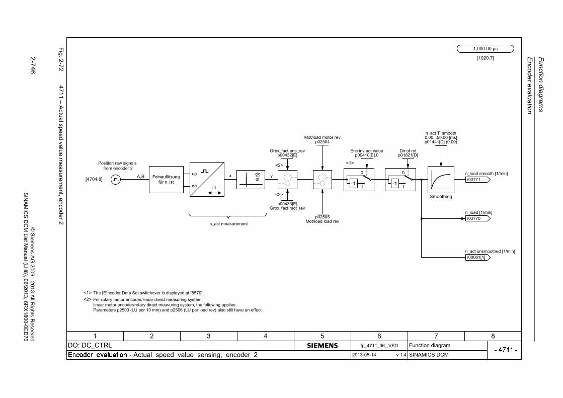
Fu
nction d
iagram
s
En
code
r evalua
tion
2-7
46©
Siem
ens AG
2009-
2013 All R
ights Reserved
SIN
AM
ICS
DC
M ListM
anual (LH8), 06/2013
, 6RX
1800-0ED
76
Fig. 2
-72
4711 – A
ctual sp
eed value m
easurem
ent, enco
der2

En
code
r evaluation
Fun
ction
diag
ram
s
2-7
47©
Siem
ens AG
2009
-20
13 All R
ights Reserved
SIN
AM
ICS
DC
M ListM
anual (LH
8), 06/2013, 6RX
1800-0E
D7
6
Fig. 2
-73
4720 – E
ncode
r interface, receive
signals, encod
ers 1...2
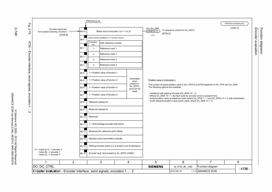
Fu
nction d
iagram
s
En
code
r evalua
tion
2-7
48©
Siem
ens AG
2009-
2013 All R
ights Reserved
SIN
AM
ICS
DC
M ListM
anual (LH8), 06/2013
, 6RX
1800-0ED
76
Fig. 2
-74
4730 – E
ncode
r interface, send
signals, encod
ers 1...2

En
code
r evaluation
Fun
ction
diag
ram
s
2-7
49©
Siem
ens AG
2009
-20
13 All R
ights Reserved
SIN
AM
ICS
DC
M ListM
anual (LH
8), 06/2013, 6RX
1800-0E
D7
6
Fig. 2
-75
4735 – R
eference m
ark search, encoders
1...
2

Fu
nction d
iagram
s
En
code
r evalua
tion
2-7
50©
Siem
ens AG
2009-
2013 All R
ights Reserved
SIN
AM
ICS
DC
M ListM
anual (LH8), 06/2013
, 6RX
1800-0ED
76
Fig. 2
-76
4750 – A
bsolute valu
e for in
crem
ental enco
der
>1_
+
+
+
SM config extp00437[E].13
XIST1_ERW res modep04652[0...1] (0)

Armature circuit closed-loop control
Function diagrams
2-751© Siemens AG 2009 - 2013 All Rights ReservedSINAMICS DCM List Manual (LH8), 06/2013, 6RX1800-0ED76
2.11 Armature circuit closed-loop control
Function diagrams
6800 – Speed controller start pulse 2-752
6805 – Speed controller (Part 1) 2-753
6810 – Speed controller (Part 2) 2-754
6812 – Speed controller (Part 3) 2-755
6815 – Speed controller (Part 4) 2-756
6820 – Friction/moment of inertia compensation 2-757
6825 – Torque limiting (Part 1) 2-758
6830 – Torque limiting (Part 2) 2-759
6835 – Speed limiting controller 2-760
6840 – Current limitation (Part 1) 2-761
6845 – Current limitation (Part 2) 2-762
6850 – Armature current actual value sensing (Part 1) 2-763
6851 – Armature current actual value sensing (Part 2) 2-764
6852 – EMF actual value selection for armature current precontrol 2-765
6853 – Armature current controller adaptation 2-766
6854 – Armature circuit model parameters 2-767
6855 – Armature current closed-loop control 2-768
6858 – Gating unit characteristic, linearization 2-769
6860 – Auto-reversing stage, armature gating unit 2-770
6862 – Limitations, state 2-771
6865 – Simulation mode/thyristor check/commutation monitoring 2-772
6895 – Line-dependent EMF reduction 2-773

Fu
nction d
iagram
s
Arm
atu
re circu
it closed
-loop co
ntrol
2-7
52©
Siem
ens AG
2009-
2013 All R
ights Reserved
SIN
AM
ICS
DC
M ListM
anual (LH8), 06/2013
, 6RX
1800-0ED
76
Fig. 2
-77
6800 – S
peed
contro
ller start pulse
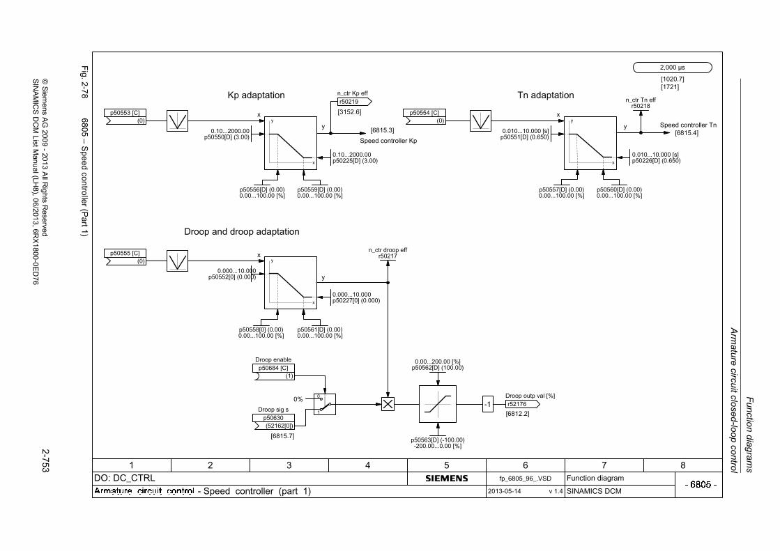
Arm
ature circuit close
d-loop
con
trol
Fun
ction
diag
ram
s
2-7
53©
Siem
ens AG
2009
-20
13 All R
ights Reserved
SIN
AM
ICS
DC
M ListM
anual (LH
8), 06/2013, 6RX
1800-0E
D7
6
Fig. 2
-78
6805 – S
peed
contro
ller (Part1)

Fu
nction d
iagram
s
Arm
atu
re circu
it closed
-loop co
ntrol
2-7
54©
Siem
ens AG
2009-
2013 All R
ights Reserved
SIN
AM
ICS
DC
M ListM
anual (LH8), 06/2013
, 6RX
1800-0ED
76
Fig. 2
-79
6810 – S
peed
contro
ller (Part2)

Arm
ature circuit close
d-loop
con
trol
Fun
ction
diag
ram
s
2-7
55©
Siem
ens AG
2009
-20
13 All R
ights Reserved
SIN
AM
ICS
DC
M ListM
anual (LH
8), 06/2013, 6RX
1800-0E
D7
6
Fig. 2
-80
6812 – S
peed
contro
ller (Part3)
[1020.7]
+
p50237[D] p50238[D] p50239[D]
+
+
+
[6805.8]
[1721]
+

Fu
nction d
iagram
s
Arm
atu
re circu
it closed
-loop co
ntrol
2-7
56©
Siem
ens AG
2009-
2013 All R
ights Reserved
SIN
AM
ICS
DC
M ListM
anual (LH8), 06/2013
, 6RX
1800-0ED
76
Fig. 2
-81
6815 – S
peed
contro
ller (Part4)
1
0+
+
+
+
+

Arm
ature circuit close
d-loop
con
trol
Fun
ction
diag
ram
s
2-7
57©
Siem
ens AG
2009
-20
13 All R
ights Reserved
SIN
AM
ICS
DC
M ListM
anual (LH
8), 06/2013, 6RX
1800-0E
D7
6
Fig. 2
-82
6820 – F
riction/m
omen
t of inertia compe
nsation
ddt

Fu
nction d
iagram
s
Arm
atu
re circu
it closed
-loop co
ntrol
2-7
58©
Siem
ens AG
2009-
2013 All R
ights Reserved
SIN
AM
ICS
DC
M ListM
anual (LH8), 06/2013
, 6RX
1800-0ED
76
Fig. 2
-83
6825 – T
orque lim
iting (P
art1)

Arm
ature circuit close
d-loop
con
trol
Fun
ction
diag
ram
s
2-7
59©
Siem
ens AG
2009
-20
13 All R
ights Reserved
SIN
AM
ICS
DC
M ListM
anual (LH
8), 06/2013, 6RX
1800-0E
D7
6
Fig. 2
-84
6830 – T
orque lim
iting (P
art2)
M
M
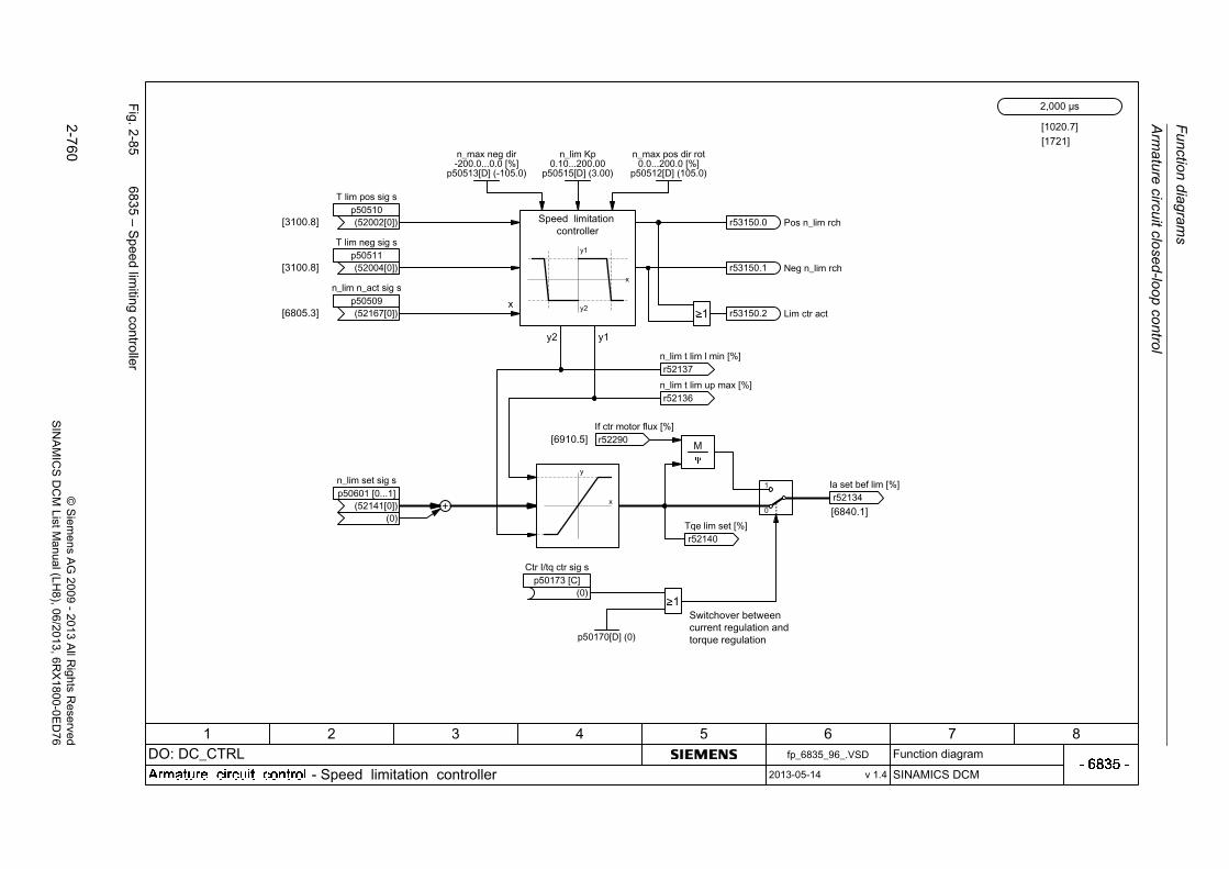
Fu
nction d
iagram
s
Arm
atu
re circu
it closed
-loop co
ntrol
2-7
60©
Siem
ens AG
2009-
2013 All R
ights Reserved
SIN
AM
ICS
DC
M ListM
anual (LH8), 06/2013
, 6RX
1800-0ED
76
Fig. 2
-85
6835 – S
peed
limiting controller
M

Arm
ature circuit close
d-loop
con
trol
Fun
ction
diag
ram
s
2-7
61©
Siem
ens AG
2009
-20
13 All R
ights Reserved
SIN
AM
ICS
DC
M ListM
anual (LH
8), 06/2013, 6RX
1800-0E
D7
6
Fig. 2
-86
6840 – C
urrent limitation
(Part1
)

Fu
nction d
iagram
s
Arm
atu
re circu
it closed
-loop co
ntrol
2-7
62©
Siem
ens AG
2009-
2013 All R
ights Reserved
SIN
AM
ICS
DC
M ListM
anual (LH8), 06/2013
, 6RX
1800-0ED
76
Fig. 2
-87
6845 – C
urrent limitation
(Part2
)
1
0
<1>
<1>

Arm
ature circuit close
d-loop
con
trol
Fun
ction
diag
ram
s
2-7
63©
Siem
ens AG
2009
-20
13 All R
ights Reserved
SIN
AM
ICS
DC
M ListM
anual (LH
8), 06/2013, 6RX
1800-0E
D7
6
Fig. 2
-88
6850 – A
rmature
current actual value sensing (P
art1)
AD
AD
ddt
3
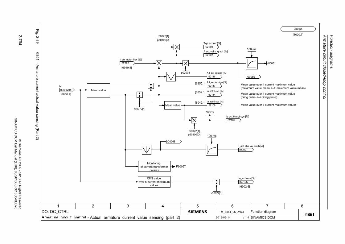
Fu
nction d
iagram
s
Arm
atu
re circu
it closed
-loop co
ntrol
2-7
64©
Siem
ens AG
2009-
2013 All R
ights Reserved
SIN
AM
ICS
DC
M ListM
anual (LH8), 06/2013
, 6RX
1800-0ED
76
Fig. 2
-89
6851 – A
rmature
current actual value sensing (P
art2)

Arm
ature circuit close
d-loop
con
trol
Fun
ction
diag
ram
s
2-7
65©
Siem
ens AG
2009
-20
13 All R
ights Reserved
SIN
AM
ICS
DC
M ListM
anual (LH
8), 06/2013, 6RX
1800-0E
D7
6
Fig. 2
-90
6852 – E
MF
actu
al value se
lection for armatu
re curre
nt precontrol
12341,35 *

Fu
nction d
iagram
s
Arm
atu
re circu
it closed
-loop co
ntrol
2-7
66©
Siem
ens AG
2009-
2013 All R
ights Reserved
SIN
AM
ICS
DC
M ListM
anual (LH8), 06/2013
, 6RX
1800-0ED
76
Fig. 2
-91
6853 – A
rmature
current controller adap
tation
[1020.7]
+
0
1
0
1
100%
p50570[D]
p50574[D]
p50573[D]
p50571[D]
p50078[0]
p50110[D]r50072[1]
p50100[D]
p51591[D]r50072[1]
0
1
p50572[D]
100%
[1721]

Arm
ature circuit close
d-loop
con
trol
Fun
ction
diag
ram
s
2-7
67©
Siem
ens AG
2009
-20
13 All R
ights Reserved
SIN
AM
ICS
DC
M ListM
anual (LH
8), 06/2013, 6RX
1800-0E
D7
6
Fig. 2
-92
6854 – A
rmature
circuit mode
l param
eters
+
+

Fu
nction d
iagram
s
Arm
atu
re circu
it closed
-loop co
ntrol
2-7
68©
Siem
ens AG
2009-
2013 All R
ights Reserved
SIN
AM
ICS
DC
M ListM
anual (LH8), 06/2013
, 6RX
1800-0ED
76
Fig. 2
-93
6855 – A
rmature
current close
d-loop co
ntrol
+
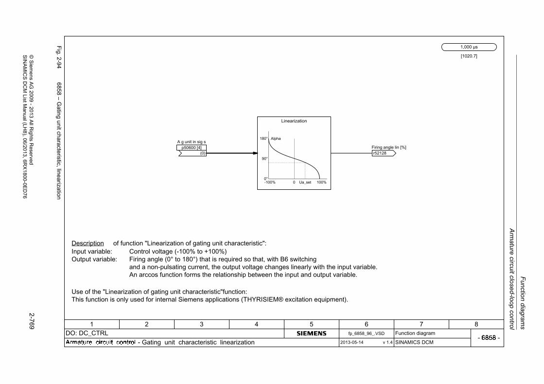
Arm
ature circuit close
d-loop
con
trol
Fun
ction
diag
ram
s
2-7
69©
Siem
ens AG
2009
-20
13 All R
ights Reserved
SIN
AM
ICS
DC
M ListM
anual (LH
8), 06/2013, 6RX
1800-0E
D7
6
Fig. 2
-94
6858 – G
ating u
nit characteristic, linea
rization

Fu
nction d
iagram
s
Arm
atu
re circu
it closed
-loop co
ntrol
2-7
70©
Siem
ens AG
2009-
2013 All R
ights Reserved
SIN
AM
ICS
DC
M ListM
anual (LH8), 06/2013
, 6RX
1800-0ED
76
Fig. 2
-95
6860 – A
uto
-reversing
stage, arm
ature gating unit
0
10
Seq ph ctr on/hysp51797[0...1] (35)

Arm
ature circuit close
d-loop
con
trol
Fun
ction
diag
ram
s
2-7
71©
Siem
ens AG
2009
-20
13 All R
ights Reserved
SIN
AM
ICS
DC
M ListM
anual (LH
8), 06/2013, 6RX
1800-0E
D7
6
Fig. 2
-96
6862 – Lim
itations, sta
te

Fu
nction d
iagram
s
Arm
atu
re circu
it closed
-loop co
ntrol
2-7
72©
Siem
ens AG
2009-
2013 All R
ights Reserved
SIN
AM
ICS
DC
M ListM
anual (LH8), 06/2013
, 6RX
1800-0ED
76
Fig. 2
-97
6865 – S
imu
lation m
ode/th
yristor che
ck/comm
utation monito
ring

Arm
ature circuit close
d-loop
con
trol
Fun
ction
diag
ram
s
2-7
73©
Siem
ens AG
2009
-20
13 All R
ights Reserved
SIN
AM
ICS
DC
M ListM
anual (LH
8), 06/2013, 6RX
1800-0E
D7
6
Fig. 2
-98
6895 – Line
-depende
nt EM
F redu
ction
[1020.7]
p50285[D] (0.00 s)p50286[D] (110.0 %)
p50287[D] (0.0 %)
+
100%
-0
1
0%
p50288[D] (100.0 %)

Function diagrams
Field circuit closed-loop control
2-774 © Siemens AG 2009 - 2013 All Rights ReservedSINAMICS DCM List Manual (LH8), 06/2013, 6RX1800-0ED76
2.12 Field circuit closed-loop control
Function diagrams
6900 – EMF closed-loop control 2-775
6902 – Actual value acquisition, armature voltage/EMF 2-776
6905 – Field current setpoint limiting 2-777
6908 – Field current controller adaptation 2-778
6910 – Field current closed-loop control 2-779
6912 – Field current actual value sensing 2-780
6915 – Field gating unit 2-781
6920 – Field reversal 2-782

Fie
ld circuit close
d-loop
con
trol
Fun
ction
diag
ram
s
2-7
75©
Siem
ens AG
2009
-20
13 All R
ights Reserved
SIN
AM
ICS
DC
M ListM
anual (LH
8), 06/2013, 6RX
1800-0E
D7
6
Fig. 2
-99
6900 – E
MF
closed-loop control
+

Fu
nction d
iagram
s
Fie
ld circu
it closed
-loop co
ntrol
2-7
76©
Siem
ens AG
2009-
2013 All R
ights Reserved
SIN
AM
ICS
DC
M ListM
anual (LH8), 06/2013
, 6RX
1800-0ED
76
Fig. 2
-100
6902 – A
ctual va
lue acquisition
, armature voltag
e/EM
F
p51854
<1>p51855
Ua slave
<2>
<1><2>

Fie
ld circuit close
d-loop
con
trol
Fun
ction
diag
ram
s
2-7
77©
Siem
ens AG
2009
-20
13 All R
ights Reserved
SIN
AM
ICS
DC
M ListM
anual (LH
8), 06/2013, 6RX
1800-0E
D7
6
Fig. 2
-101
6905 – F
ield current setp
oint lim
iting
[1]
If freeze op_modep50269 (2)
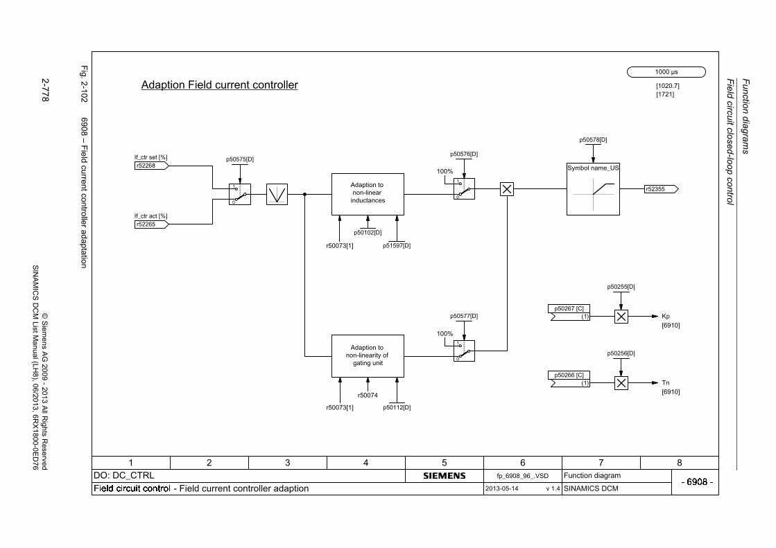
Fu
nction d
iagram
s
Fie
ld circu
it closed
-loop co
ntrol
2-7
78©
Siem
ens AG
2009-
2013 All R
ights Reserved
SIN
AM
ICS
DC
M ListM
anual (LH8), 06/2013
, 6RX
1800-0ED
76
Fig. 2
-102
6908 – F
ield current controlle
r adaptation
[1020.7]
+
0
1
0
1
100%
p50575[D]
p50578[D]
p50576[D]
p50112[D]r50073[1]
p50102[D]
p51597[D]r50073[1]
0
1
p50577[D]
100%
r50074
p50255[D]
[6910]
p50256[D]
[6910]
[1721]
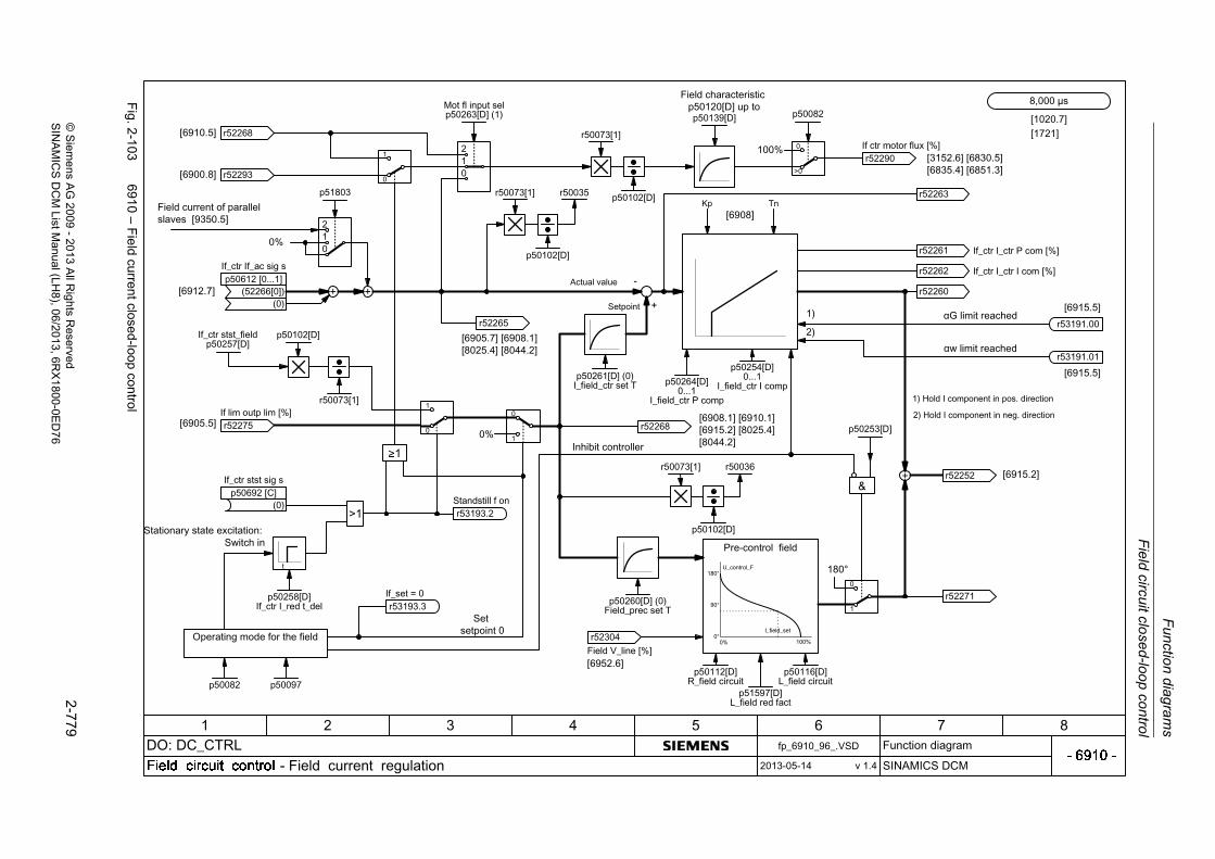
Fie
ld circuit close
d-loop
con
trol
Fun
ction
diag
ram
s
2-7
79©
Siem
ens AG
2009
-20
13 All R
ights Reserved
SIN
AM
ICS
DC
M ListM
anual (LH
8), 06/2013, 6RX
1800-0E
D7
6
Fig. 2
-103
6910 – F
ield current closed
-loop con
trol
10
2
10
2

Fu
nction d
iagram
s
Fie
ld circu
it closed
-loop co
ntrol
2-7
80©
Siem
ens AG
2009-
2013 All R
ights Reserved
SIN
AM
ICS
DC
M ListM
anual (LH8), 06/2013
, 6RX
1800-0ED
76
Fig. 2
-104
6912 – F
ield current actu
al value se
nsing

Fie
ld circuit close
d-loop
con
trol
Fun
ction
diag
ram
s
2-7
81©
Siem
ens AG
2009
-20
13 All R
ights Reserved
SIN
AM
ICS
DC
M ListM
anual (LH
8), 06/2013, 6RX
1800-0E
D7
6
Fig. 2
-105
6915 – F
ield gatin
g unit

Fu
nction d
iagram
s
Fie
ld circu
it closed
-loop co
ntrol
2-7
82©
Siem
ens AG
2009-
2013 All R
ights Reserved
SIN
AM
ICS
DC
M ListM
anual (LH8), 06/2013
, 6RX
1800-0ED
76
Fig. 2
-106
6920 – F
ield reversal
Rs = Rs V1
++
+ +
+
+
Rs
8,000 μs
[1020.7]
M K20 K21
1C1 1D1 3C 3D
*)
+
+
+
+
[6805.2]
[6805.3]
r53026.01If_act < If_set x
r53026.00If < If_min
[8025.5]
[8025.5]
19
X177
20
23
k21
K20
k20
K21
CUD
+
+
+
++
CUD DO 0 t_delp50775 (0)
CUD DO invp50770[0] (0)
CUD DO 1 t_delp50776 (0)
CUD DO invp50770[1] (0)
M
p50092[0]0.0...10.0 [s]
2
Rs V1
++
+ +
r53195.02n_act invert
[6810.1]

Power unit
Function diagrams
2-783© Siemens AG 2009 - 2013 All Rights ReservedSINAMICS DCM List Manual (LH8), 06/2013, 6RX1800-0ED76
2.13 Power unit
Function diagrams
6950 – Line analysis, armature 2-784
6952 – Line analysis, field 2-785
6954 – Line monitoring 2-786
6956 – Fuse monitoring (DC converter) 2-787
6957 – Fuse monitoring (Control Module) 2-788
6960 – Power unit, properties 2-789
6965 – Adaptation to external power unit (Control Module) 2-790
6970 – Converter Commutation Protector (CCP) 2-791

Fu
nction d
iagram
s
Pow
er unit
2-7
84©
Siem
ens AG
2009-
2013 All R
ights Reserved
SIN
AM
ICS
DC
M ListM
anual (LH8), 06/2013
, 6RX
1800-0ED
76
Fig. 2
-107
6950 – Line
analysis, arm
ature
6

Po
we
r un
it
Fun
ction
diag
ram
s
2-7
85©
Siem
ens AG
2009
-20
13 All R
ights Reserved
SIN
AM
ICS
DC
M ListM
anual (LH
8), 06/2013, 6RX
1800-0E
D7
6
Fig. 2
-108
6952 – Line
analysis, field
<1>
<1>
<1>
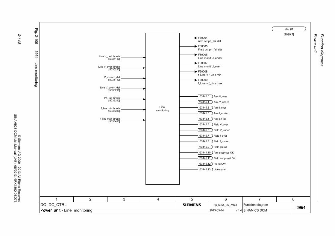
Fu
nction d
iagram
s
Pow
er unit
2-7
86©
Siem
ens AG
2009-
2013 All R
ights Reserved
SIN
AM
ICS
DC
M ListM
anual (LH8), 06/2013
, 6RX
1800-0ED
76
Fig. 2
-109
6954 – Line
mon
itoring

Po
we
r un
it
Fun
ction
diag
ram
s
2-7
87©
Siem
ens AG
2009
-20
13 All R
ights Reserved
SIN
AM
ICS
DC
M ListM
anual (LH
8), 06/2013, 6RX
1800-0E
D7
6
Fig. 2
-110
6956 – F
use m
onito
ring (DC
converter)

Fu
nction d
iagram
s
Pow
er unit
2-7
88©
Siem
ens AG
2009-
2013 All R
ights Reserved
SIN
AM
ICS
DC
M ListM
anual (LH8), 06/2013
, 6RX
1800-0ED
76
Fig. 2
-111
6957 – F
use m
onito
ring (Con
trolMod
ule)
++++
++++

Po
we
r un
it
Fun
ction
diag
ram
s
2-7
89©
Siem
ens AG
2009
-20
13 All R
ights Reserved
SIN
AM
ICS
DC
M ListM
anual (LH
8), 06/2013, 6RX
1800-0E
D7
6
Fig. 2
-112
6960 – P
ow
er unit, propertie
s
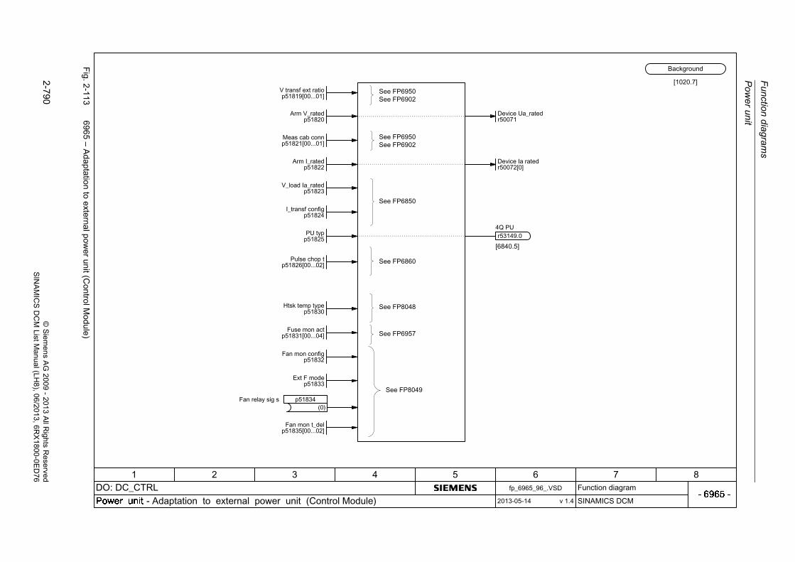
Fu
nction d
iagram
s
Pow
er unit
2-7
90©
Siem
ens AG
2009-
2013 All R
ights Reserved
SIN
AM
ICS
DC
M ListM
anual (LH8), 06/2013
, 6RX
1800-0ED
76
Fig. 2
-113
6965 – A
daptation
to external p
ower un
it (Con
trolMod
ule)
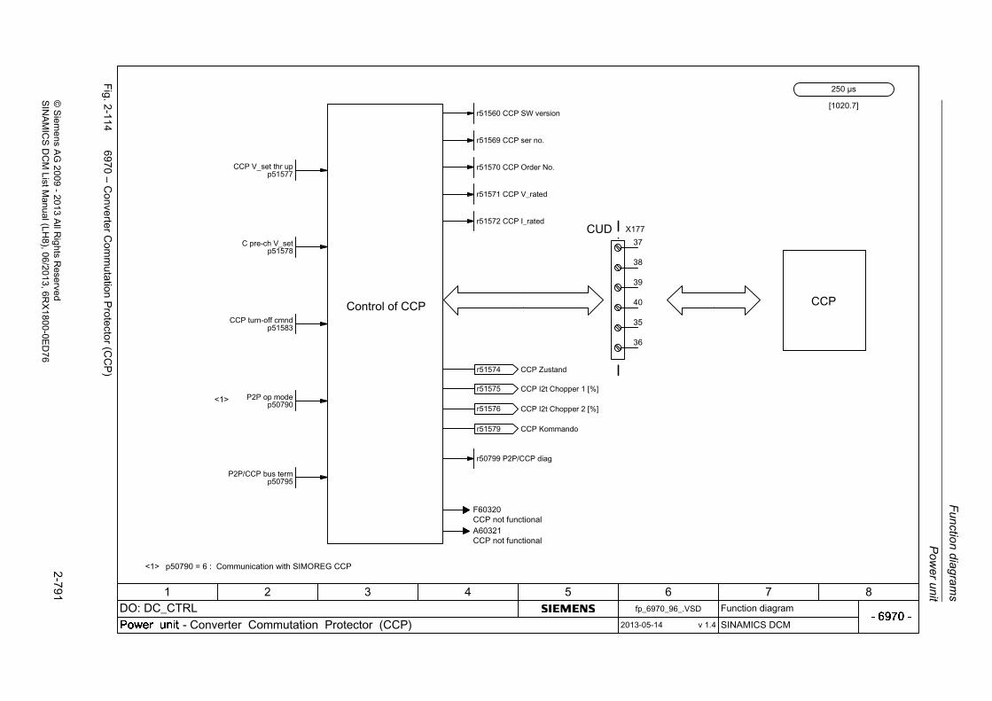
Po
we
r un
it
Fun
ction
diag
ram
s
2-7
91©
Siem
ens AG
2009
-20
13 All R
ights Reserved
SIN
AM
ICS
DC
M ListM
anual (LH
8), 06/2013, 6RX
1800-0E
D7
6
Fig. 2
-114
6970 – C
onverter Com
mutation P
rotector (CC
P)
CCP V_set thr upp51577
C pre-ch V_setp51578
CCP turn-off cmndp51583
P2P op modep50790
P2P/CCP bus termp50795
<1>
<1>
[1020.7]

Function diagrams
Technology controller
2-792 © Siemens AG 2009 - 2013 All Rights ReservedSINAMICS DCM List Manual (LH8), 06/2013, 6RX1800-0ED76
2.14 Technology controller
Function diagrams
7958 – Closed-loop control (r0108.16 = 1) 2-793

Te
chno
logy co
ntroller
Fun
ction
diag
ram
s
2-7
93©
Siem
ens AG
2009
-20
13 All R
ights Reserved
SIN
AM
ICS
DC
M ListM
anual (LH
8), 06/2013, 6RX
1800-0E
D7
6
Fig. 2
-115
7958 – C
losed-loop
contro
l (r0108.16
=1
)
+ + + +
Tec_ctrl set1 scal0.00...100.00 [%]p02255 (100.00)
Tec_ctrl set2 scal0.00...100.00 [%]p02256 (100.00)
Tec_ctrl t_ramp-up0.00...650.00 [s]p02257 (1.00)
Tec_ctrl configp02252.0
Tec_ctrl set T0.000...60.000 [s]p02261 (0.000)
[1020.7]<101>
Tec_ctrl outp scal-100.00...100.00 [%]
p02295 (100.00)
Tec_ctrl Tn0.000...60.000 [s]p02285 (0.000)
Tec_ctrl Kp0.000...1000.000 p02280 (1.000)
+
+
+
+
Tec_ctrl max_lim-200.00...200.00 [%]
p02291 (100.00)
Tec_ctrl min_lim-200.00...200.00 [%]
p02292 (0.00)
p02252.2
+p02252.2
p02293 (1.00)0.00...100.00 [s]
Tec_ctr ramp up/dn
+
1
-1
0 1
++
Tec_ctrl D comp T0.000...60.000 [s]p02274 (0.000)
+
Tec_ctrl type0...1
p02263 (0)
Tec_ctr ActVal fct0...3
p02270 (0)
Tech_ctrl act inv0...1
p02271 (0)
Tech_ctrl gain act0.00...500.00 [%]p02269 (100.00)
p02258 (1.00)0.00...650.00 [s]
Tec_ctrl t_ramp-dn
Tec_ctrl u_lim act-200.00...200.00 [%]
p02267 (200.00)
+
Tec_ctrl act T0.000...60.000 [s]p02265 (0.000)
Tec_ctrl l_lim act-200.00...200.00 [%]
p02268 (-200.00)
y
x
<1><2><3>
<101>
+
+
<2>
+ + + + +
+
+ -
+
-
<3>
<1>
<1><2>
<2>
<2><1>
p02252.1
ddt
p02252.3Tec_ctrl config

Function diagrams
Signals and monitoring functions
2-794 © Siemens AG 2009 - 2013 All Rights ReservedSINAMICS DCM List Manual (LH8), 06/2013, 6RX1800-0ED76
2.15 Signals and monitoring functions
Function diagrams
8020 – Messages (Part 1) 2-795
8025 – Messages (Part 2) 2-796
8030 – Motor interface (Part 1, X177.53/54/55) 2-797
8035 – Motor interface (Part 2) 2-798
8038 – I2t monitoring motor 2-799
8040 – Speed-dependent current limitation 2-800
8042 – I2t monitoring power unit 2-801
8044 – Field current monitoring 2-802
8045 – Device fan operating hours counter 2-803
8046 – Monitoring stall protection/tachometer break 2-804
8047 – Device fan (DC converter) 2-805
8048 – Internal device monitoring functions 2-806
8049 – Device fan (Control Module) 2-807
8050 – Trend recorder function 2-808
8052 – Diagnostic memory 2-809
8054 – Internal diagnostics 2-810

Sign
als a
nd m
onitoring
functio
ns
Fun
ction
diag
ram
s
2-7
95©
Siem
ens AG
2009
-20
13 All R
ights Reserved
SIN
AM
ICS
DC
M ListM
anual (LH
8), 06/2013, 6RX
1800-0E
D7
6
Fig. 2
-116
8020 – M
essa
ges (Part1)
0
1

Fu
nction d
iagram
s
Sig
nals an
d m
onito
ring fu
nctions
2-7
96©
Siem
ens AG
2009-
2013 All R
ights Reserved
SIN
AM
ICS
DC
M ListM
anual (LH8), 06/2013
, 6RX
1800-0ED
76
Fig. 2
-117
8025 – M
essa
ges (Part2)
0
1
Msg n > 0 hyst0.00...10.00 [%]p50372[D] (0.10)
Msg n > 0 hyst0.00...10.00 [%]p50372[D] (0.10)
0
1
0
1
0
1

Sign
als a
nd m
onitoring
functio
ns
Fun
ction
diag
ram
s
2-7
97©
Siem
ens AG
2009
-20
13 All R
ights Reserved
SIN
AM
ICS
DC
M ListM
anual (LH
8), 06/2013, 6RX
1800-0E
D7
6
Fig. 2
-118
8030 – M
oto
r inte
rface (P
art1, X
177.5
3/54/55)
Mot_temp_sens typep00601[M]

Fu
nction d
iagram
s
Sig
nals an
d m
onito
ring fu
nctions
2-7
98©
Siem
ens AG
2009-
2013 All R
ights Reserved
SIN
AM
ICS
DC
M ListM
anual (LH8), 06/2013
, 6RX
1800-0ED
76
Fig. 2
-119
8035 – M
oto
r inte
rface (P
art2)

Sign
als a
nd m
onitoring
functio
ns
Fun
ction
diag
ram
s
2-7
99©
Siem
ens AG
2009
-20
13 All R
ights Reserved
SIN
AM
ICS
DC
M ListM
anual (LH
8), 06/2013, 6RX
1800-0E
D7
6
Fig. 2
-120
8038 – I2t m
onitoring m
oto
r
100 %
110 %

Fu
nction d
iagram
s
Sig
nals an
d m
onito
ring fu
nctions
2-8
00©
Siem
ens AG
2009-
2013 All R
ights Reserved
SIN
AM
ICS
DC
M ListM
anual (LH8), 06/2013
, 6RX
1800-0ED
76
Fig. 2
-121
8040 – S
peed
-depe
ndent curren
t limitatio
n

Sign
als a
nd m
onitoring
functio
ns
Fun
ction
diag
ram
s
2-8
01©
Siem
ens AG
2009
-20
13 All R
ights Reserved
SIN
AM
ICS
DC
M ListM
anual (LH
8), 06/2013, 6RX
1800-0E
D7
6
Fig. 2
-122
8042 – I2t m
onitoring pow
er un
it
PU I2t mon deratp50077 (1.00)
PU fact K1 lim valp50066 (0.50)
0
1

Fu
nction d
iagram
s
Sig
nals an
d m
onito
ring fu
nctions
2-8
02©
Siem
ens AG
2009-
2013 All R
ights Reserved
SIN
AM
ICS
DC
M ListM
anual (LH8), 06/2013
, 6RX
1800-0ED
76
Fig. 2
-123
8044 – F
ield current m
onitorin
g
Ext field monitp51839 (0)
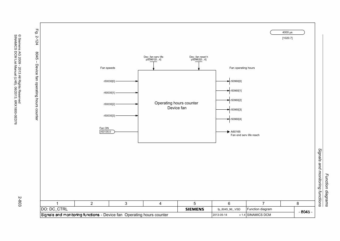
Sign
als a
nd m
onitoring
functio
ns
Fun
ction
diag
ram
s
2-8
03©
Siem
ens AG
2009
-20
13 All R
ights Reserved
SIN
AM
ICS
DC
M ListM
anual (LH
8), 06/2013, 6RX
1800-0E
D7
6
Fig. 2
-124
8045 – D
evice fan operating ho
urs counter
Dev_fan serv lifep50961[0...4]
Dev_fan reset hp50962[0...4]
[1020.7]

Fu
nction d
iagram
s
Sig
nals an
d m
onito
ring fu
nctions
2-8
04©
Siem
ens AG
2009-
2013 All R
ights Reserved
SIN
AM
ICS
DC
M ListM
anual (LH8), 06/2013
, 6RX
1800-0ED
76
Fig. 2
-125
8046 – M
onitorin
g stall protection/ta
chometer break
&0T
1%
&0T
0,5s
1%
&0T
0,5s
1%

Sign
als a
nd m
onitoring
functio
ns
Fun
ction
diag
ram
s
2-8
05©
Siem
ens AG
2009
-20
13 All R
ights Reserved
SIN
AM
ICS
DC
M ListM
anual (LH
8), 06/2013, 6RX
1800-0E
D7
6
Fig. 2
-126
8047 – D
evice fan (DC
converter)

Fu
nction d
iagram
s
Sig
nals an
d m
onito
ring fu
nctions
2-8
06©
Siem
ens AG
2009-
2013 All R
ights Reserved
SIN
AM
ICS
DC
M ListM
anual (LH8), 06/2013
, 6RX
1800-0ED
76
Fig. 2
-127
8048 – Intern
al device m
onitoring
functions
XT5
XT6
XT7

Sign
als a
nd m
onitoring
functio
ns
Fun
ction
diag
ram
s
2-8
07©
Siem
ens AG
2009
-20
13 All R
ights Reserved
SIN
AM
ICS
DC
M ListM
anual (LH
8), 06/2013, 6RX
1800-0E
D7
6
Fig. 2
-128
8049 – D
evice fan (ControlM
odule)
+
+

Fu
nction d
iagram
s
Sig
nals an
d m
onito
ring fu
nctions
2-8
08©
Siem
ens AG
2009-
2013 All R
ights Reserved
SIN
AM
ICS
DC
M ListM
anual (LH8), 06/2013
, 6RX
1800-0ED
76
Fig. 2
-129
8050 – T
rend re
corder function

Sign
als a
nd m
onitoring
functio
ns
Fun
ction
diag
ram
s
2-8
09©
Siem
ens AG
2009
-20
13 All R
ights Reserved
SIN
AM
ICS
DC
M ListM
anual (LH
8), 06/2013, 6RX
1800-0E
D7
6
Fig. 2
-130
8052 – D
iagnostic m
em
ory
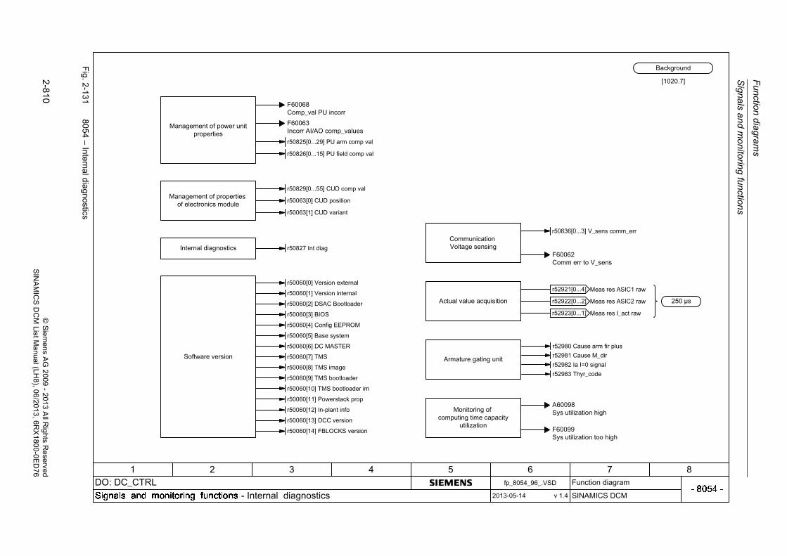
Fu
nction d
iagram
s
Sig
nals an
d m
onito
ring fu
nctions
2-8
10©
Siem
ens AG
2009-
2013 All R
ights Reserved
SIN
AM
ICS
DC
M ListM
anual (LH8), 06/2013
, 6RX
1800-0ED
76
Fig. 2
-131
8054 – Intern
al diagnostics

Faults and alarms
Function diagrams
2-811© Siemens AG 2009 - 2013 All Rights ReservedSINAMICS DCM List Manual (LH8), 06/2013, 6RX1800-0ED76
2.16 Faults and alarms
Function diagrams
8060 – Fault buffer 2-812
8065 – Alarm buffer 2-813
8070 – Fault/alarm trigger word (r2129) 2-814
8075 – Fault/alarm configuration 2-815

Fu
nction d
iagram
s
Fa
ults and
alarm
s
2-8
12©
Siem
ens AG
2009-
2013 All R
ights Reserved
SIN
AM
ICS
DC
M ListM
anual (LH8), 06/2013
, 6RX
1800-0ED
76
Fig. 2
-132
8060 – F
ault bu
ffer
p2108,p3110...p3112
p2108,p3110...p3112
p2106p2106
p2107p2107
p2102...p2105p2102...p2105
p3981p3981
r02114[0]

Fau
lts and
alarm
s
Fun
ction
diag
ram
s
2-8
13©
Siem
ens AG
2009
-20
13 All R
ights Reserved
SIN
AM
ICS
DC
M ListM
anual (LH
8), 06/2013, 6RX
1800-0E
D7
6
Fig. 2
-133
8065 – A
larm b
uffer
p2112p2112
p2116p2116
p2117p2117

Fu
nction d
iagram
s
Fa
ults and
alarm
s
2-8
14©
Siem
ens AG
2009-
2013 All R
ights Reserved
SIN
AM
ICS
DC
M ListM
anual (LH8), 06/2013
, 6RX
1800-0ED
76
Fig. 2
-134
8070 – F
ault/alarm
trigger w
ord (r2129)

Fau
lts and
alarm
s
Fun
ction
diag
ram
s
2-8
15©
Siem
ens AG
2009
-20
13 All R
ights Reserved
SIN
AM
ICS
DC
M ListM
anual (LH
8), 06/2013, 6RX
1800-0E
D7
6
Fig. 2
-135
8075 – F
ault/alarm
configuratio
n

Function diagrams
Data sets
2-816 © Siemens AG 2009 - 2013 All Rights ReservedSINAMICS DCM List Manual (LH8), 06/2013, 6RX1800-0ED76
2.17 Data sets
Function diagrams
8560 – Command Data Sets (CDS) 2-817
8565 – Drive Data Sets (DDS) 2-818
8570 – Encoder Data Sets (EDS) 2-819

Data sets
Fun
ction
diag
ram
s
2-8
17©
Siem
ens AG
2009
-20
13 All R
ights Reserved
SIN
AM
ICS
DC
M ListM
anual (LH
8), 06/2013, 6RX
1800-0E
D7
6
Fig. 2
-136
8560 – C
omm
and Data S
ets (CD
S)

Fu
nction d
iagram
s
Data sets
2-8
18©
Siem
ens AG
2009-
2013 All R
ights Reserved
SIN
AM
ICS
DC
M ListM
anual (LH8), 06/2013
, 6RX
1800-0ED
76
Fig. 2
-137
8565 – D
rive Data S
ets (DD
S)

Data sets
Fun
ction
diag
ram
s
2-8
19©
Siem
ens AG
2009
-20
13 All R
ights Reserved
SIN
AM
ICS
DC
M ListM
anual (LH
8), 06/2013, 6RX
1800-0E
D7
6
Fig. 2
-138
8570 – E
ncode
r Data S
ets (ED
S)
Function diagrams
Communication between devices
2-820 © Siemens AG 2009 - 2013 All Rights ReservedSINAMICS DCM List Manual (LH8), 06/2013, 6RX1800-0ED76
2.18 Communication between devices
Function diagrams
9300 – Peer-to-peer interface 2-821
9350 – Paralleling interface (Part 1) 2-822
9352 – Paralleling interface (Part 2) 2-823
9355 – Paralleling interface (Part 3) 2-824
9360 – Switchover of the power unit topology 2-825

Co
mm
unication
betw
een
device
s
Fun
ction
diag
ram
s
2-8
21©
Siem
ens AG
2009
-20
13 All R
ights Reserved
SIN
AM
ICS
DC
M ListM
anual (LH
8), 06/2013, 6RX
1800-0E
D7
6
Fig. 2
-139
9300 – P
eer-to
-peer interface
1
0+
1
p51118.0
1
0+
1
p51118.15 +

Fu
nction d
iagram
s
Co
mm
unica
tion be
twe
en de
vices
2-8
22©
Siem
ens AG
2009-
2013 All R
ights Reserved
SIN
AM
ICS
DC
M ListM
anual (LH8), 06/2013
, 6RX
1800-0ED
76
Fig. 2
-140
9350 – P
aralle
ling interfa
ce (Pa
rt1)
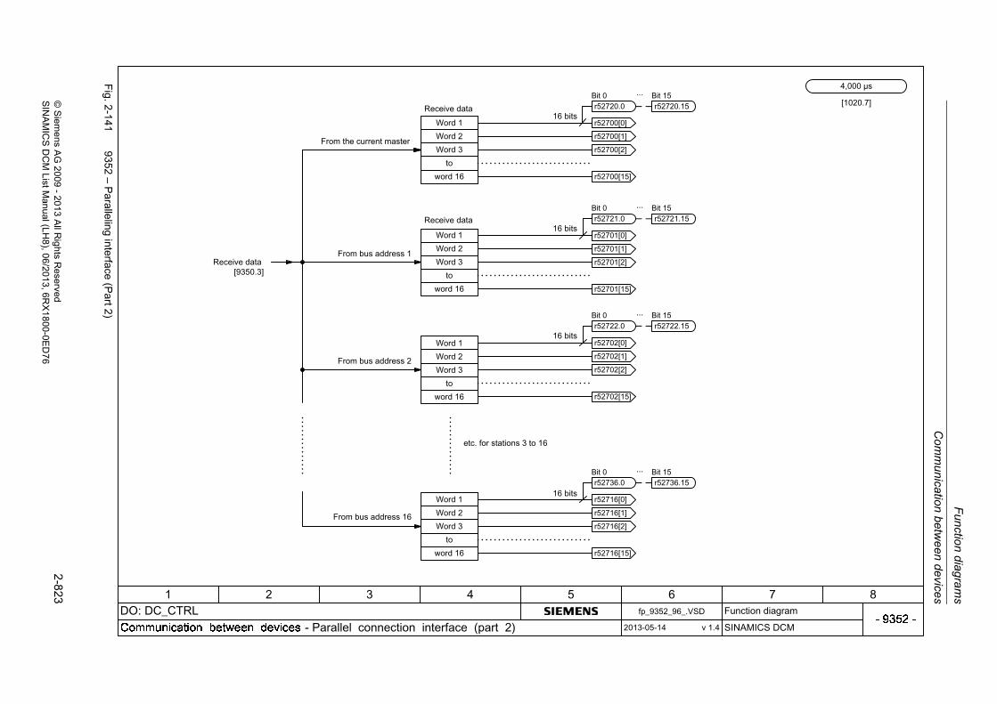
Co
mm
unication
betw
een
device
s
Fun
ction
diag
ram
s
2-8
23©
Siem
ens AG
2009
-20
13 All R
ights Reserved
SIN
AM
ICS
DC
M ListM
anual (LH
8), 06/2013, 6RX
1800-0E
D7
6
Fig. 2
-141
9352 – P
aralle
ling interfa
ce (Pa
rt2)

Fu
nction d
iagram
s
Co
mm
unica
tion be
twe
en de
vices
2-8
24©
Siem
ens AG
2009-
2013 All R
ights Reserved
SIN
AM
ICS
DC
M ListM
anual (LH8), 06/2013
, 6RX
1800-0ED
76
Fig. 2
-142
9355 – P
aralle
ling interfa
ce (Pa
rt3)
1
0

Co
mm
unication
betw
een
device
s
Fun
ction
diag
ram
s
2-8
25©
Siem
ens AG
2009
-20
13 All R
ights Reserved
SIN
AM
ICS
DC
M ListM
anual (LH
8), 06/2013, 6RX
1800-0E
D7
6
Fig. 2
-143
9360 – S
witch
over of the pow
er unit topology
19
X177
20
23
k31-1
K30
k30-1
K31
CUD
+
+
+
++
CUD DO 0 t_delp50775 (0)
CUD DO invp50770[0] (0)
CUD DO 1 t_delp50776 (0)
CUD DO invp50770[1] (0)
M
Topo_sw t_stabp51792
==
P24_S
11
9
k31-2
SINAMICS DCM 1
p51800=21p51795=31
C D
U1V1W1
+
+
+
SINAMICS DCM 2
p51800=22p51795=32
C D
U2V2W2
+
+
+
K30
K31M+
+
+
+ +
53312.0
[9360.6]
[9360.2] [8565.3]
+
Topo_sw fdbk t_sigp51793
Topo_sw mode 2p51794
Topo_sw pos 2p51795
Function diagrams
Terminal Module 15 for SINAMICS (TM15DI/DO)
2-826 © Siemens AG 2009 - 2013 All Rights ReservedSINAMICS DCM List Manual (LH8), 06/2013, 6RX1800-0ED76
2.19 Terminal Module 15 for SINAMICS (TM15DI/DO)
Function diagrams
9400 – Digital inputs/outputs, bidirectional (DI/DO 0 ... DI/DO 7) 2-827
9401 – Digital inputs/outputs, bidirectional (DI/DO 8 ... DI/DO 15) 2-828
9402 – Digital inputs/outputs, bidirectional (DI/DO 16 ... DI/DO 23) 2-829

Term
inal M
odu
le 15 fo
r SIN
AM
ICS
(TM
15
DI/D
O)
Fun
ction
diag
ram
s
2-8
27©
Siem
ens AG
2009
-20
13 All R
ights Reserved
SIN
AM
ICS
DC
M ListM
anual (LH
8), 06/2013, 6RX
1800-0E
D7
6
Fig. 2
-144
9400 – D
igital inputs/outputs, bidirectio
nal (DI/D
O0
...DI/D
O7)
24 VDC to the next device

Fu
nction d
iagram
s
Te
rmina
l Mo
dule 15
for SIN
AM
ICS
(TM
15D
I/DO
)
2-8
28©
Siem
ens AG
2009-
2013 All R
ights Reserved
SIN
AM
ICS
DC
M ListM
anual (LH8), 06/2013
, 6RX
1800-0ED
76
Fig. 2
-145
9401 – D
igital inputs/outputs, bidirectio
nal (DI/D
O8
...DI/D
O15
)
24 VDC to the next device

Term
inal M
odu
le 15 fo
r SIN
AM
ICS
(TM
15
DI/D
O)
Fun
ction
diag
ram
s
2-8
29©
Siem
ens AG
2009
-20
13 All R
ights Reserved
SIN
AM
ICS
DC
M ListM
anual (LH
8), 06/2013, 6RX
1800-0E
D7
6
Fig. 2
-146
9402 – D
igital inputs/outputs, bidirectio
nal (DI/D
O16
...DI/D
O2
3)
24 VDC to the next device

Function diagrams
Terminal Module 31 (TM31)
2-830 © Siemens AG 2009 - 2013 All Rights ReservedSINAMICS DCM List Manual (LH8), 06/2013, 6RX1800-0ED76
2.20 Terminal Module 31 (TM31)
Function diagrams
9550 – Digital inputs, isolated (DI 0 ... DI 3) 2-831
9552 – Digital inputs, isolated (DI 4 ... DI 7) 2-832
9556 – Digital relay outputs, isolated (DO 0 ... DO 1) 2-833
9560 – Digital inputs/outputs, bidirectional (DI/DO 8 ... DI/DO 9) 2-834
9562 – Digital inputs/outputs, bidirectional (DI/DO 10 ... DI/DO 11) 2-835
9566 – Analog input 0 (AI 0) 2-836
9568 – Analog input 1 (AI 1) 2-837
9572 – Analog outputs (AO 0 ... AO 1) 2-838
9576 – Temperature evaluation KTY/PTC 2-839
9577 – Sensor monitoring KTY/PTC 2-840

Term
inal M
odu
le 31 (T
M3
1)
Fun
ction
diag
ram
s
2-8
31©
Siem
ens AG
2009
-20
13 All R
ights Reserved
SIN
AM
ICS
DC
M ListM
anual (LH
8), 06/2013, 6RX
1800-0E
D7
6
Fig. 2
-147
9550 – D
igital inputs, isolated (D
I0...D
I3)
24 VDC to the next device

Fu
nction d
iagram
s
Te
rmina
l Mo
dule 31
(TM
31
)
2-8
32©
Siem
ens AG
2009-
2013 All R
ights Reserved
SIN
AM
ICS
DC
M ListM
anual (LH8), 06/2013
, 6RX
1800-0ED
76
Fig. 2
-148
9552 – D
igital inputs, isolated (D
I4...D
I7)
24 VDC to the next device

Term
inal M
odu
le 31 (T
M3
1)
Fun
ction
diag
ram
s
2-8
33©
Siem
ens AG
2009
-20
13 All R
ights Reserved
SIN
AM
ICS
DC
M ListM
anual (LH
8), 06/2013, 6RX
1800-0E
D7
6
Fig. 2
-149
9556 – D
igital relay outputs, iso
lated (DO
0...
DO
1)

Fu
nction d
iagram
s
Te
rmina
l Mo
dule 31
(TM
31
)
2-8
34©
Siem
ens AG
2009-
2013 All R
ights Reserved
SIN
AM
ICS
DC
M ListM
anual (LH8), 06/2013
, 6RX
1800-0ED
76
Fig. 2
-150
9560 – D
igital inputs/outputs, bidirectio
nal (DI/D
O8
...DI/D
O9)
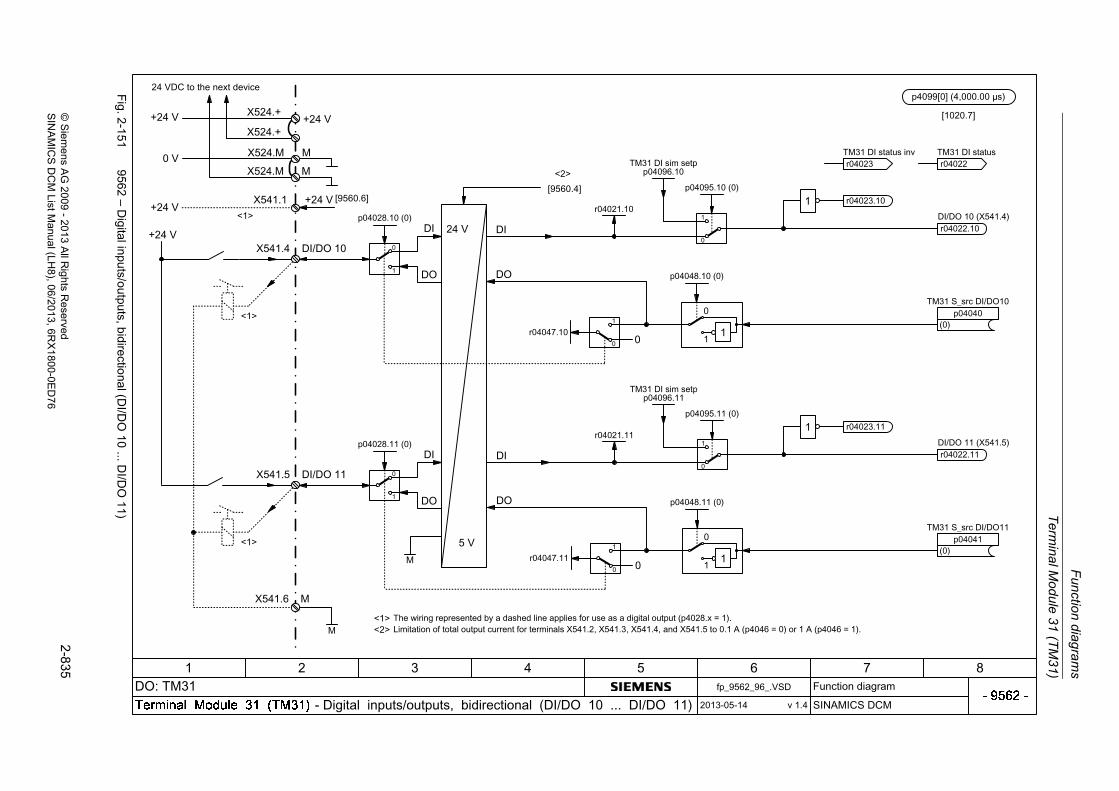
Term
inal M
odu
le 31 (T
M3
1)
Fun
ction
diag
ram
s
2-8
35©
Siem
ens AG
2009
-20
13 All R
ights Reserved
SIN
AM
ICS
DC
M ListM
anual (LH
8), 06/2013, 6RX
1800-0E
D7
6
Fig. 2
-151
9562 – D
igital inputs/outputs, bidirectio
nal (DI/D
O10
...DI/D
O1
1)
24 VDC to the next device

Fu
nction d
iagram
s
Te
rmina
l Mo
dule 31
(TM
31
)
2-8
36©
Siem
ens AG
2009-
2013 All R
ights Reserved
SIN
AM
ICS
DC
M ListM
anual (LH8), 06/2013
, 6RX
1800-0ED
76
Fig. 2
-152
9566 – A
nalo
g input0 (A
I0)
% 100xx 21�

Term
inal M
odu
le 31 (T
M3
1)
Fun
ction
diag
ram
s
2-8
37©
Siem
ens AG
2009
-20
13 All R
ights Reserved
SIN
AM
ICS
DC
M ListM
anual (LH
8), 06/2013, 6RX
1800-0E
D7
6
Fig. 2
-153
9568 – A
nalo
g input1 (A
I1)
% 100xx 21�

Fu
nction d
iagram
s
Te
rmina
l Mo
dule 31
(TM
31
)
2-8
38©
Siem
ens AG
2009-
2013 All R
ights Reserved
SIN
AM
ICS
DC
M ListM
anual (LH8), 06/2013
, 6RX
1800-0ED
76
Fig. 2
-154
9572 – A
nalo
g outputs (AO
0...A
O1)
21
x% 100x �

Term
inal M
odu
le 31 (T
M3
1)
Fun
ction
diag
ram
s
2-8
39©
Siem
ens AG
2009
-20
13 All R
ights Reserved
SIN
AM
ICS
DC
M ListM
anual (LH
8), 06/2013, 6RX
1800-0E
D7
6
Fig. 2
-155
9576 – T
empe
rature evaluation K
TY
/PT
C
248 °C
-140 °C
>1_
0
1
0
1

Fu
nction d
iagram
s
Te
rmina
l Mo
dule 31
(TM
31
)
2-8
40©
Siem
ens AG
2009-
2013 All R
ights Reserved
SIN
AM
ICS
DC
M ListM
anual (LH8), 06/2013
, 6RX
1800-0ED
76
Fig. 2
-156
9577 – S
ensor m
onitoring K
TY
/PT
C

Terminal Module 150 (TM150)
Function diagrams
2-841© Siemens AG 2009 - 2013 All Rights ReservedSINAMICS DCM List Manual (LH8), 06/2013, 6RX1800-0ED76
2.21 Terminal Module 150 (TM150)
Function diagrams
9625 – Temperature evaluation structure (channels 0 ... 11) 2-842
9626 – Temperature evaluation 1x2, 3, 4-wire (channels 0 ... 5) 2-843
9627 – Temperature evaluation 2x2-wire (channels 0 ... 11) 2-844
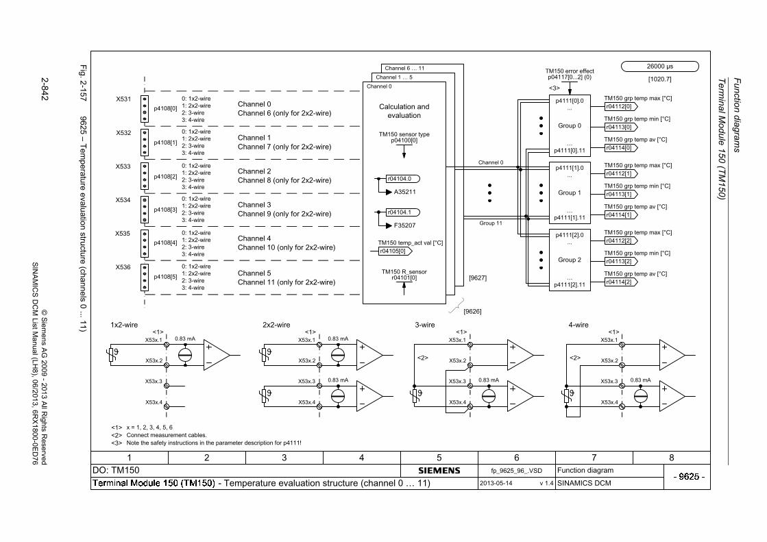
Fu
nction d
iagram
s
Te
rmina
l Mo
dule 15
0 (T
M1
50)
2-8
42©
Siem
ens AG
2009-
2013 All R
ights Reserved
SIN
AM
ICS
DC
M ListM
anual (LH8), 06/2013
, 6RX
1800-0ED
76
Fig. 2
-157
9625 – T
empe
rature evaluation stru
cture
(channe
ls0
...11)
+
+
0.83 mA
�
X53x.1
X53x.2
X53x.3
X53x.4+
++
+
0.83 mA
�
X53x.1
X53x.2
X53x.3
X53x.4
++
+
0.83 mA
�
X53x.1
X53x.2
X53x.3
X53x.4
�+
+
0.83 mAX53x.1
X53x.2
X53x.3
X53x.4
�+
+
0.83 mA
p4108[0]
p4108[1]
p4108[2]
p4108[3]
p4108[4]
p4108[5]
X531
X532
X533
X534
X535
X536
TM150 sensor typep04100[0]
+
+
++
++
+
+
+
+
+
+
+
+
+
+
+
+
TM150 error effectp04117[0...2] (0)

Term
ina
l Mod
ule 1
50 (T
M15
0)
Fun
ction
diag
ram
s
2-8
43©
Siem
ens AG
2009
-20
13 All R
ights Reserved
SIN
AM
ICS
DC
M ListM
anual (LH
8), 06/2013, 6RX
1800-0E
D7
6
Fig. 2
-158
9626 – T
empe
rature evalua
tion 1x2, 3, 4
-wire (chann
els0
...5)
654210
X53x.1X53x.2X53x.3X53x.4
AD
TM150 meas methodp04108[0...5]
p04121 (0)TM150 filt f_line
10
+
TM150 smooth actp04119[0...5] (0)
TM150 R_wire valuep04110[0...5]
+
TM150 R_wire measp04109[0...5]
T
R
T
R
T
R
+
+
+
+
10
-50 °C250 °C
-300 °C
+
TM150 sensor typep04100[0...5]
0
1
TM150 F/A_thresh-99...251 [°C]
p04102[0, 2, 4, 6, 8, 10] (251)
p04118[0...5]TM150 thresh hyst
T 0
TM150 t_delayp04103[0...5] (0.0)
0
1
TM150 F/A_thresh-99...251 [°C]
p04102[1, 3, 5, 7, 9, 11] (251)
p04118[0...5]TM150 thresh hyst
>1_
+
+
+
+
1
0
-300 °C
+
+
1
0
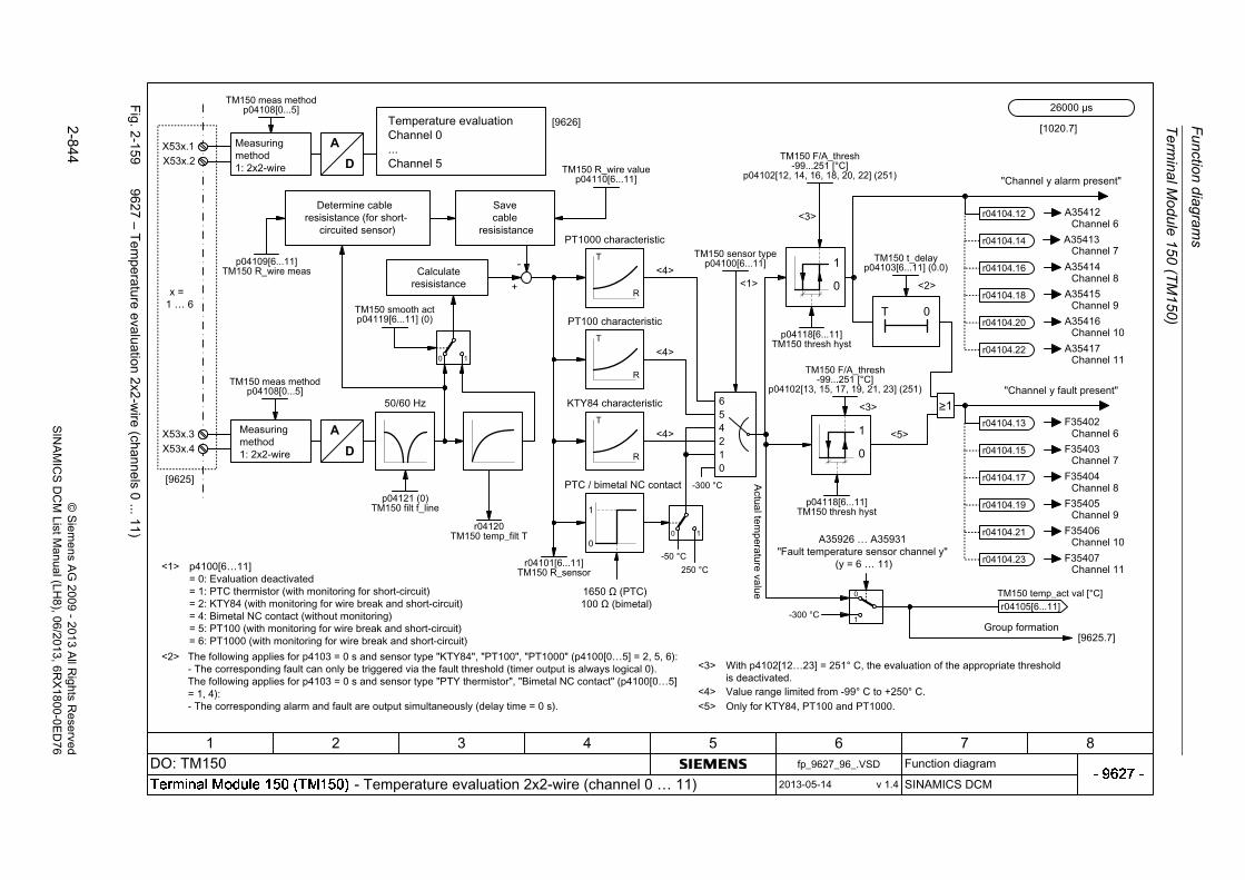
Fu
nction d
iagram
s
Te
rmina
l Mo
dule 15
0 (T
M1
50)
2-8
44©
Siem
ens AG
2009-
2013 All R
ights Reserved
SIN
AM
ICS
DC
M ListM
anual (LH8), 06/2013
, 6RX
1800-0ED
76
Fig. 2
-159
9627 – T
empe
rature evaluation 2x2
-wire (ch
annels
0...11
)
654210
X53x.1X53x.2
X53x.3X53x.4
AD
TM150 meas methodp04108[0...5]
p04121 (0)TM150 filt f_line
10
+
TM150 smooth actp04119[6...11] (0)
TM150 R_wire valuep04110[6...11]
+
p04109[6...11]TM150 R_wire meas
T
R
T
R
T
R
+
+
+
+
10
-50 °C250 °C
-300 °C
+
TM150 sensor typep04100[6...11]
0
1
TM150 F/A_thresh-99...251 [°C]
p04102[12, 14, 16, 18, 20, 22] (251)
p04118[6...11]TM150 thresh hyst
T 0
TM150 t_delayp04103[6...11] (0.0)
0
1
TM150 F/A_thresh-99...251 [°C]
p04102[13, 15, 17, 19, 21, 23] (251)
p04118[6...11]TM150 thresh hyst
>1_
+
+
+
+
1
0
-300 °C
+
+
AD
TM150 meas methodp04108[0...5]
1
0

Basic Operator Panel 20 (BOP20)
Function diagrams
2-845© Siemens AG 2009 - 2013 All Rights ReservedSINAMICS DCM List Manual (LH8), 06/2013, 6RX1800-0ED76
2.22 Basic Operator Panel 20 (BOP20)
Function diagrams
9912 – Control word interconnection 2-846

Fu
nction d
iagram
s
Ba
sic Op
era
tor P
an
el 20 (B
OP
20
)
2-8
46©
Siem
ens AG
2009-
2013 All R
ights Reserved
SIN
AM
ICS
DC
M ListM
anual (LH8), 06/2013
, 6RX
1800-0ED
76
Fig. 2
-160
9912 – C
ontrol word
inte
rconne
ction

3-847© Siemens AG 2009 - 2013 All Rights ReservedSINAMICS DCM List Manual (LH8), 06/2013, 6RX1800-0ED76
Faults and alarms 3Content
3.1 Overview of faults and alarms 3-848
3.2 List of faults and alarms 3-857

Faults and alarms
Overview of faults and alarms
3-848 © Siemens AG 2009 - 2013 All Rights ReservedSINAMICS DCM List Manual (LH8), 06/2013, 6RX1800-0ED76
3.1 Overview of faults and alarms
3.1.1 General information on faults and alarms
Fault/alarm displays
In the case of a fault, the drive signals the corresponding fault(s) and/or alarm(s).
The following methods are available for displaying faults and alarms:
• Display via the fault and alarm buffer for PROFIBUS.
• In online operation, display via the commissioning software.
Differences between faults and alarms
The differences between faults and alarms are as follows:
Table 3-1 Differences between faults and alarms
Type Description
Faults What happens when a fault occurs?
• The appropriate fault reaction is triggered.
• Status signal ZSW1.3 is set.
• The fault is entered into the fault buffer.
How are faults removed?
• Remove the original cause of the fault.
• Acknowledge the fault.
Alarms What happens when an alarm occurs?
• Status signal ZSW1.7 is set.
• The alarm is entered into the alarm buffer.
How are alarms removed?
• Alarms acknowledge themselves. If the cause of the alarm is no longer present, they automatically reset themselves.
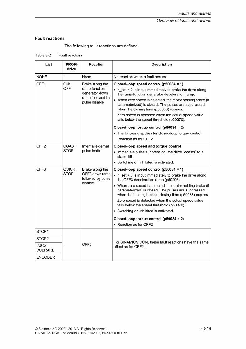
Overview of faults and alarms
Faults and alarms
3-849© Siemens AG 2009 - 2013 All Rights ReservedSINAMICS DCM List Manual (LH8), 06/2013, 6RX1800-0ED76
Fault reactions
The following fault reactions are defined:
Table 3-2 Fault reactions
List PROFI-drive
Reaction Description
NONE - None No reaction when a fault occurs
OFF1 ON/OFF
Brake along the ramp-function generator down ramp followed by pulse disable
Closed-loop speed control (p50084 = 1)
• n_set = 0 is input immediately to brake the drive along the ramp-function generator deceleration ramp.
• When zero speed is detected, the motor holding brake (if parameterized) is closed. The pulses are suppressed when the closing time (p50088) expires.
Zero speed is detected when the actual speed value falls below the speed threshold (p50370).
Closed-loop torque control (p50084 = 2)
• The following applies for closed-loop torque control:
Reaction as for OFF2
OFF2 COAST STOP
Internal/external pulse inhibit
Closed-loop speed and torque control
• Immediate pulse suppression, the drive “coasts” to a standstill.
• Switching on inhibited is activated.
OFF3 QUICK STOP
Brake along the OFF3 down ramp followed by pulse disable
Closed-loop speed control (p50084 = 1)
• n_set = 0 is input immediately to brake the drive along the OFF3 deceleration ramp (p50296).
• When zero speed is detected, the motor holding brake (if parameterized) is closed. The pulses are suppressed when the holding brake's closing time (p50088) expires.
Zero speed is detected when the actual speed value falls below the speed threshold (p50370).
• Switching on inhibited is activated.
Closed-loop torque control (p50084 = 2)
• Reaction as for OFF2
STOP1
- OFF2For SINAMICS DCM, these fault reactions have the same effect as for OFF2.
STOP2
IASC/DCBRAKE
ENCODER

Faults and alarms
Overview of faults and alarms
3-850 © Siemens AG 2009 - 2013 All Rights ReservedSINAMICS DCM List Manual (LH8), 06/2013, 6RX1800-0ED76
Acknowledgement of faults
The list of faults and alarms specifies how to acknowledge each fault after the cause has been removed.
Table 3-3 Acknowledgement of faults
Acknowledgment
Description
POWER ON The fault is acknowledged by a POWER ON (switch drive unit off and on again).
Note:
If this action has not removed the fault cause, the fault is displayed again immediately after power up.
IMMEDIATELY Faults can be acknowledged on one drive object (Points 1 to 3) or on all drive objects (Point 4) as follows:
1 Acknowledge by setting parameter:
p3981 = 0 --> 1
2 Acknowledge via binector inputs:
p2103
p2104
p2105
BI: 1. Acknowledge faults
BI: 2. Acknowledge faults
BI: 3. Acknowledge faults
3 Acknowledge using a PROFIBUS control signal:
STW1.7 = 0 --> 1 (edge)
4 Acknowledge all faults
p2102 BI: Acknowledge all faults
All of the faults on all of the drive objects of the drive system can be acknowledged using this binector input.
Note:
• These faults can also be acknowledged by a POWER ON.
• If the cause of the fault has not been removed, then the fault will continue to be displayed after acknowledgment.
PULSE INHIBIT The fault can only be acknowledged when the pulses are inhibited (r0899.11 = 0).
The same options are available for acknowledging as described under acknowledge IMMEDIATELY.

Overview of faults and alarms
Faults and alarms
3-851© Siemens AG 2009 - 2013 All Rights ReservedSINAMICS DCM List Manual (LH8), 06/2013, 6RX1800-0ED76
Saving the fault buffer when switching off
The contents of the fault buffer are saved to the non-volatile memory when the Control Unit is switched off, i.e. the fault buffer history is still available when the unit is switched on again.
The fault buffer of a drive object comprises the following parameters:
• r0945[0...63], r0947[0...63], r0948[0...63], r0949[0...63]
• r2109[0...63], r2130[0...63], r2133[0...63], r2136[0...63]
The fault buffer contents can be deleted manually as follows:
• Delete fault buffer for all drive objects:p2147 = 1 --> p2147 = 0 is automatically set after execution.
• Delete fault buffer for a specific drive object:p0952 = 0 --> The parameter belongs to the specified drive object.
The fault buffer contents are automatically deleted when the following occurs:
• Restore factory setting (p0009 = 30 and p0976 = 1).
• Download with modified structure (e.g. number of drive objects changed).
• Power-up after other parameter values have been loaded (e.g. p0976 = 10).
• Upgrade firmware to later version.

Faults and alarms
Overview of faults and alarms
3-852 © Siemens AG 2009 - 2013 All Rights ReservedSINAMICS DCM List Manual (LH8), 06/2013, 6RX1800-0ED76
3.1.2 Explanation of the list of faults and alarms
The data in the following example have been chosen at random. The information listed below is the maximum amount of information that a description can contain. Some of the information is optional.
The list of faults and alarms (See Chapter 3.2) is structured as follows:
Axxxxx Alarm xxxxxAxxxxx (F, N) Alarm xxxxx (message type can be changed in F or N)Fxxxxx Fault xxxxxFxxxxx (A, N) Fault xxxxx (message type can be changed in A or N)Nxxxxx No messageNxxxxx (A) No message (message type can be changed in A)
A message comprises a letter followed by the relevant number.
The meaning of the letters is as follows:
• A means "Alarm"
• F means "Fault"
• N means "No message" or "Internal message" (or "No report")
The optional brackets indicate whether the type specified for this message can be changed and which message types can be adjusted via parameter (p2118, p2119).
Information about reaction and acknowledgement is specified independently for a message with adjustable message type (e.g. reaction to F, acknowledgement for F).
- - - - - - - - - - - - - - - - - - - - - - - - - Start of the example - - - - - - - - - - - - - - - - - - - - - - - - - - - - - - - - - - - - - - - - - - -
Axxxxx (F, N) Fault location (optional): NameMessage value: Component number: %1, fault cause: %2
Drive object: List of objects.
Reaction: NONE
Acknowledge: NONE
Cause: Description of possible causes.Fault value (r0949, interpret format): or alarm value (r2124, interpret format): (optional)Information about fault or alarm values (optional).
Remedy: Description of possible remedies.
Reaction upon F: NONE (OFF1, OFF2, OFF3)
Acknowl. upon F: IMMEDIATELY (POWER ON)
Reaction upon N: NONE
Acknowl. upon N: NONE
- - - - - - - - - - - - - - - - - - - - - - - - - End of the example - - - - - - - - - - - - - - - - - - - - - - - - - - - - - - - - - - - - - - - - - - - -

Overview of faults and alarms
Faults and alarms
3-853© Siemens AG 2009 - 2013 All Rights ReservedSINAMICS DCM List Manual (LH8), 06/2013, 6RX1800-0ED76
Fault location (optional): Name
The fault location (optional), the name of the fault or alarm and the message num-ber are all used to identify the message (e.g. with the commissioning software).
Message value:
The information provided under the message value tells you about the composition of the fault/alarm value.
Example:
Message value: Component number: %1, fault cause: %2
This message value contains information about the component number and cause of the fault. The entries %1 and %2 are placeholders, which are filled appropriately in online operation (e.g. with the commissioning software).
Drive object:
Each message (fault/alarm) specifies the drive object in which it can be found.
A message can belong to either one, several, or all drive objects.
Reaction: Default fault reaction (adjustable fault reaction)
Specifies the default reaction in the event of a fault.
The optional parentheses indicate whether the default fault reactions can be changed and which fault reactions can be adjusted via parameters (p2100, p2101).
Note:
See Chapter 3.1.1
Note:
You can change the default properties of a fault or alarm by setting parameters.
References: SINAMICS DC MASTER operating instructions
The list of faults and alarms (see Chapter 3.2) provides information referred to the properties of a message that have been set as standard. If the properties of a spe-cific message are changed, the corresponding information may have to be modi-fied in this list.

Faults and alarms
Overview of faults and alarms
3-854 © Siemens AG 2009 - 2013 All Rights ReservedSINAMICS DCM List Manual (LH8), 06/2013, 6RX1800-0ED76
Acknowledgment: Default acknowledgment (adjustable acknowledgment)
Specifies the default method of acknowledging faults after the cause has been eliminated.
The optional parentheses indicate whether the default acknowledgement can be changed and which acknowledgement can be adjusted via parameters (p2126, p2127).
Note:
See Chapter 3.1.1
Cause:
Description of the possible causes of the fault/alarm. A fault or alarm value can also be specified (optional).
Fault value (r0949, format):
The fault value is entered into the fault buffer in r0949[0...63] and specifies addi-tional, more precise information about a fault.
Alarm value (r2124, format):
The alarm value specifies additional, more precise information about an alarm.
The alarm value is entered in the alarm buffer in r2124[0...7] and specifies addi-tional, more precise information about an alarm.
Remedy:
Description of the methods available for removing the cause of the active fault or alarm.
Alarm
In certain cases, servicing and maintenance personnel are responsible for choos-ing a suitable method to remove the fault cause.

Overview of faults and alarms
Faults and alarms
3-855© Siemens AG 2009 - 2013 All Rights ReservedSINAMICS DCM List Manual (LH8), 06/2013, 6RX1800-0ED76
3.1.3 Number ranges of faults and alarms
Faults and alarms are organized into the following number ranges:
Note:
The following number ranges represent an overview of all faults and alarms asso-ciated with the SINAMICS drive range.
The faults and alarms for the product described in this List Manual are described in detail in Chapter 3.2.
Table 3-4 Number ranges of faults and alarms
from to Range
1000 3999 Control Unit, closed-loop control
4000 4999 Reserved
5000 5999 Power unit
6000 6899 Infeed
6900 6999 Braking Module
7000 7999 Drive
8000 8999 Option Board
9000 12999 Reserved
13000 13020 Licensing
13021 13099 Reserved
13100 13102 Know-how protection
13103 19999 Reserved
20000 29999 OEM
30000 30999 DRIVE-CLiQ component power unit
31000 31999 DRIVE-CLiQ component encoder 1
32000 32999 DRIVE-CLiQ component encoder 2
Note
Faults that occur are automatically output as an alarm if the encoder is parameterized as a direct measuring system and does not intervene in the motor control.
33000 33999 DRIVE-CLiQ component encoder 3
Note
Faults that occur are automatically output as an alarm if the encoder is parameterized as a direct measuring system and does not intervene in the motor control.
34000 34999 Voltage Sensing Module (VSM)
35000 35199 Terminal Module 54F (TM54F)

Faults and alarms
Overview of faults and alarms
3-856 © Siemens AG 2009 - 2013 All Rights ReservedSINAMICS DCM List Manual (LH8), 06/2013, 6RX1800-0ED76
35200 35999 Terminal Module 31 (TM31)
36000 36999 DRIVE-CLiQ Hub Module
37000 37999 HF Damping Module
40000 40999 Controller Extension 32 (CX32)
41000 48999 Reserved
49000 49999 SINAMICS GM/SM/GL
50000 50499 Communication Board (COMM BOARD)
50500 59999 OEM Siemens
60000 65535 SINAMICS DC MASTER (DC closed-loop control)
Table 3-4 Number ranges of faults and alarms, continued
from to Range

List of faults and alarms
Faults and alarms
3-857© Siemens AG 2009 - 2013 All Rights ReservedSINAMICS DCM List Manual (LH8), 06/2013, 6RX1800-0ED76
3.2 List of faults and alarms
Product: SINAMICS DC MASTER, Version: 4601800, Language: engObjects: CU_DC, CU_DC_R, CU_DC_R_S, CU_DC_S, DC_CTRL, DC_CTRL_R, DC_CTRL_R_S, DC_CTRL_S, TM150, TM15DI_DO, TM31Product: SINAMICS DC MASTER OA, Version: 1400800, Language: engObjects: DC_CTRL
F01000 Internal software errorMessage value: Module: %1, line: %2
Drive object: All objects
Reaction: OFF2
Acknowledge: POWER ON
Cause: An internal software error has occurred.Fault value (r0949, interpret hexadecimal):Only for internal Siemens troubleshooting.
Remedy: - evaluate fault buffer (r0945).- carry out a POWER ON (power off/on) for all components.- if required, check the data on the non-volatile memory (e.g. memory card).- upgrade firmware to later version.- contact the Hotline.- replace the Control Unit.
F01001 FloatingPoint exceptionMessage value: %1
Drive object: All objects
Reaction: OFF2
Acknowledge: POWER ON
Cause: An exception occurred during an operation with the FloatingPoint data type.The error may be caused by the basic system or an OA application (e.g., FBLOCKS, DCC).Fault value (r0949, interpret hexadecimal):Only for internal Siemens troubleshooting.Note:Refer to r9999 for further information about this fault.r9999[0]: Fault number.r9999[1]: Program counter at the time when the exception occurred.r9999[2]: Cause of the FloatingPoint exception.Bit 0 = 1: Operation invalidBit 1 = 1: Division by zeroBit 2 = 1: OverflowBit 3 = 1: UnderflowBit 4 = 1: Inaccurate result
Remedy: - carry out a POWER ON (power off/on) for all components.- check configuration and signals of the blocks in FBLOCKS.- check configuration and signals of DCC charts.- upgrade firmware to later version.- contact the Hotline.
F01002 Internal software errorMessage value: %1
Drive object: All objects
Reaction: OFF2
Acknowledge: IMMEDIATELY
Cause: An internal software error has occurred.Fault value (r0949, interpret hexadecimal):Only for internal Siemens troubleshooting.
Remedy: - carry out a POWER ON (power off/on) for all components.- upgrade firmware to later version.- contact the Hotline.

Faults and alarms
List of faults and alarms
3-858 © Siemens AG 2009 - 2013 All Rights ReservedSINAMICS DCM List Manual (LH8), 06/2013, 6RX1800-0ED76
F01003 Acknowledgement delay when accessing the memoryMessage value: %1
Drive object: All objects
Reaction: OFF2
Acknowledge: IMMEDIATELY
Cause: A memory area was accessed that does not return a "READY".Fault value (r0949, interpret hexadecimal):Only for internal Siemens troubleshooting.
Remedy: - carry out a POWER ON (power off/on) for all components.- contact the Hotline.
N01004 (F, A) Internal software errorMessage value: %1
Drive object: All objects
Reaction: NONE
Acknowledge: NONE
Cause: An internal software error has occurred.Fault value (r0949, hexadecimal):Only for internal Siemens troubleshooting.
Remedy: - read out diagnostics parameter (r9999).- contact the Hotline.See also: r9999 (Software error internal supplementary diagnostics)
Reaction upon F: OFF2
Acknowl. upon F: POWER ON
Reaction upon A: NONE
Acknowl. upon A: NONE
F01005 Firmware download for DRIVE-CLiQ component unsuccessfulMessage value: Component number: %1, fault cause: %2
Drive object: All objects
Reaction: NONE
Acknowledge: IMMEDIATELY
Cause: It was not possible to download the firmware to a DRIVE-CLiQ component.Fault value (r0949, interpret hexadecimal):yyxxxx hex: yy = component number, xxxx = fault causexxxx = 000B hex = 11 dec:DRIVE-CLiQ component has detected a checksum error.xxxx = 000F hex = 15 dec:The selected DRIVE-CLiQ component did not accept the contents of the firmware file.xxxx = 0012 hex = 18 dec:Firmware version is too old and is not accepted by the component.xxxx = 0013 hex = 19 dec:Firmware version is not suitable for the hardware release of the component.xxxx = 0065 hex = 101 dec:After several communication attempts, no response from the DRIVE-CLiQ component.xxxx = 008B hex = 139 dec:Initially, a new boot loader is loaded (must be repeated after POWER ON).xxxx = 008C hex = 140 dec:Firmware file for the DRIVE-CLiQ component not available on the memory card.xxxx = 008D hex = 141 dec:An inconsistent length of the firmware file was signaled. The firmware download may have been caused by a loss of connection to the firmware file. This can occur during a project download/reset in the case of a SINAMICS Integrated Control Unit, for example.xxxx = 008F hex = 143 dec:Component has not changed to the mode for firmware download. It was not possible to delete the existing firmware.xxxx = 0090 hex = 144 dec:When checking the firmware that was downloaded (checksum), the component detected a fault. It is possible that the file on the memory card is defective.

List of faults and alarms
Faults and alarms
3-859© Siemens AG 2009 - 2013 All Rights ReservedSINAMICS DCM List Manual (LH8), 06/2013, 6RX1800-0ED76
xxxx = 0091 hex = 145 dec:Checking the loaded firmware (checksum) was not completed by the component in the appropriate time.xxxx = 009C hex = 156 dec:Component with the specified component number is not available (p7828).xxxx = Additional values:Only for internal Siemens troubleshooting.
Remedy: - check the selected component number (p7828).- check the DRIVE-CLiQ connection.- save suitable firmware file for download in the directory "/siemens/sinamics/code/sac/".- use a component with a suitable hardware version- after POWER ON has been carried out again for the DRIVE-CLiQ component, download the firmware again. Depending on p7826, the firmware will be automatically downloaded.
A01006 Firmware update for DRIVE-CLiQ component requiredMessage value: Component number: %1
Drive object: All objects
Reaction: NONE
Acknowledge: NONE
Cause: The firmware of a DRIVE-CLiQ component must be updated as there is no suitable firmware or firmware version in the component for operation with the Control Unit.Alarm value (r2124, interpret decimal):Component number of the DRIVE-CLiQ component.
Remedy: Firmware update using the commissioning software:The firmware version of all of the components on the "Version overview" page can be read in the Project Navigator under "Configuration" of the associated drive unit and an appropriate firmware update can be carried out.Firmware update via parameter:- take the component number from the alarm value and enter into p7828.- start the firmware download with p7829 = 1.
A01007 POWER ON for DRIVE-CLiQ component requiredMessage value: Component number: %1
Drive object: All objects
Reaction: NONE
Acknowledge: NONE
Cause: A DRIVE-CLiQ component must be powered up again (POWER ON) (e.g. due to a firmware update).Alarm value (r2124, interpret decimal):Component number of the DRIVE-CLiQ component.Note:For a component number = 1, a POWER ON of the Control Unit is required.
Remedy: - Switch off the power supply of the specified DRIVE-CLiQ component and switch it on again.- For SINUMERIK, auto commissioning is prevented. In this case, a POWER ON is required for all components and the auto commissioning must be restarted.
F01010 Drive type unknownMessage value: %1
Drive object: All objects
Reaction: NONE
Acknowledge: IMMEDIATELY
Cause: An unknown drive type was found.Fault value (r0949, interpret decimal):Drive object number (refer to p0101, p0107).
Remedy: - replace Power Module.- carry out a POWER ON (power off/on) for all components.- upgrade firmware to later version.- contact the Hotline.
Faults and alarms
List of faults and alarms
3-860 © Siemens AG 2009 - 2013 All Rights ReservedSINAMICS DCM List Manual (LH8), 06/2013, 6RX1800-0ED76
F01011 (N) Download interruptedMessage value: %1
Drive object: All objects
Reaction: NONE
Acknowledge: IMMEDIATELY
Cause: The project download was interrupted.Fault value (r0949, interpret decimal):1: The user prematurely interrupted the project download.2: The communication cable was interrupted (e.g. cable breakage, cable withdrawn).3: The project download was prematurely ended by the commissioning software (e.g. STARTER, SCOUT).100: Different versions between the firmware version and project files which were loaded by loading into the file sys-tem "Download from memory card".Note:The response to an interrupted download is the state "first commissioning".
Remedy: - check the communication cable.- download the project again.- boot from previously saved files (power-down/power-up or p0976).- when loading into the file system (download from memory card), use the matching version.
Reaction upon N: NONE
Acknowl. upon N: NONE
F01015 Internal software errorMessage value: %1
Drive object: All objects
Reaction: OFF2
Acknowledge: POWER ON
Cause: An internal software error has occurred.Fault value (r0949, interpret decimal):Only for internal Siemens troubleshooting.
Remedy: - carry out a POWER ON (power off/on) for all components.- upgrade firmware to later version.- contact the Hotline.
A01016 (F) Firmware changedMessage value: %1
Drive object: All objects
Reaction: NONE
Acknowledge: NONE
Cause: At least one firmware file in the directory was illegally changed on the non-volatile memory (memory card/device memory) with respect to the version when shipped from the factory.Alarm value (r2124, interpret decimal):0: Checksum of one file is incorrect.1: File missing.2: Too many files.3: Incorrect firmware version.4: Incorrect checksum of the back-up file.
Remedy: For the non-volatile memory for the firmware (memory card/device memory), restore the delivery condition.Note:The file involved can be read out using parameter r9925.The status of the firmware check is displayed using r9926.See also: r9925 (Firmware file incorrect), r9926 (Firmware check status)
Reaction upon F: OFF2
Acknowl. upon F: POWER ON

List of faults and alarms
Faults and alarms
3-861© Siemens AG 2009 - 2013 All Rights ReservedSINAMICS DCM List Manual (LH8), 06/2013, 6RX1800-0ED76
A01017 Component lists changedMessage value: %1
Drive object: All objects
Reaction: NONE
Acknowledge: NONE
Cause: On the memory card, one file in the directory /SIEMENS/SINAMICS/DATA or /ADDON/SINAMICS/DATA has been illegally changed with respect to that supplied from the factory. No changes are permitted in this directory.Alarm value (r2124, interpret decimal):zyx dec: x = Problem, y = Directory, z = File namex = 1: File does not exist.x = 2: Firmware version of the file does not match the software version.x = 3: File checksum is incorrect.y = 0: Directory /SIEMENS/SINAMICS/DATA/y = 1: Directory /ADDON/SINAMICS/DATA/z = 0: File MOTARM.ACXz = 1: File MOTSRM.ACXz = 2: File MOTSLM.ACXz = 3: File ENCDATA.ACXz = 4: File FILTDATA.ACXz = 5: File BRKDATA.ACXz = 6: File DAT_BEAR.ACXz = 7: File CFG_BEAR.ACXz = 8: File ENC_GEAR.ACX
Remedy: For the file on the memory card involved, restore the status originally supplied from the factory.
F01018 Booting has been interrupted several timesMessage value: -
Drive object: All objects
Reaction: NONE
Acknowledge: POWER ON
Cause: Module booting was interrupted several times. As a consequence, the module boots with the factory setting.Possible reasons for booting being interrupted:- power supply interrupted.- CPU crashed.- parameterization invalid.
Remedy: - carry out a POWER ON (power off/on). After switching on, the module reboots from the valid parameterization (if available).- restore the valid parameterization.Examples:a) Carry out a first commissioning, save, carry out a POWER ON (switch-off/switch-on).b) Load another valid parameter backup (e.g. from the memory card), save, carry out a POWER ON (switch-off/switch-on).Note:If the fault situation is repeated, then this fault is again output after several interrupted boots.
A01019 Writing to the removable data medium unsuccessfulMessage value: -
Drive object: All objects
Reaction: NONE
Acknowledge: NONE
Cause: The write access to the removable data medium was unsuccessful.
Remedy: Remove and check the removable data medium. Then run the data backup again.

Faults and alarms
List of faults and alarms
3-862 © Siemens AG 2009 - 2013 All Rights ReservedSINAMICS DCM List Manual (LH8), 06/2013, 6RX1800-0ED76
A01020 Writing to RAM disk unsuccessfulMessage value: -
Drive object: All objects
Reaction: NONE
Acknowledge: NONE
Cause: A write access to the internal RAM disk was unsuccessful.
Remedy: Adapt the file size for the system logbook to the internal RAM disk (p9930).See also: p9930 (System logbook activation)
F01023 Software timeout (internal)Message value: %1
Drive object: All objects
Reaction: NONE
Acknowledge: IMMEDIATELY
Cause: An internal software timeout has occurred.Fault value (r0949, interpret decimal):Only for internal Siemens troubleshooting.
Remedy: - carry out a POWER ON (power off/on) for all components.- upgrade firmware to later version.- contact the Hotline.
F01030 Sign-of-life failure for master controlMessage value: -
Drive object: DC_CTRL, DC_CTRL_R, DC_CTRL_R_S, DC_CTRL_S
Reaction: OFF3 (IASC/DCBRK, NONE, OFF1, OFF2, STOP1, STOP2)
Acknowledge: IMMEDIATELY
Cause: For active PC master control, no sign-of-life was received within the monitoring time.The master control was returned to the active BICO interconnection.
Remedy: Set the monitoring time higher at the PC or, if required, completely disable the monitoring function.For the commissioning software, the monitoring time is set as follows:<Drive> -> Commissioning -> Control panel -> Button "Fetch master control" -> A window is displayed to set the mon-itoring time in milliseconds.Notice:The monitoring time should be set as short as possible. A long monitoring time means a late response when the communication fails!
F01031 Sign-of-life failure for OFF in REMOTEMessage value: -
Drive object: DC_CTRL, DC_CTRL_R, DC_CTRL_R_S, DC_CTRL_S
Reaction: OFF3 (IASC/DCBRK, NONE, OFF1, OFF2, STOP1, STOP2)
Acknowledge: IMMEDIATELY
Cause: With the "OFF in REMOTE" mode active, no sign-of-life was received within 3 seconds.
Remedy: - Check the data cable connection at the serial interface for the Control Unit (CU) and operator panel.- Check the data cable between the Control Unit and operator panel.
A01032 (F) ACX: all parameters must be savedMessage value: %1
Drive object: All objects
Reaction: NONE
Acknowledge: NONE
Cause: The parameters of an individual drive object were saved (p0971 = 1), although there is still no backup of all drive system parameters.The saved object-specific parameters are not loaded the next time that the system powers up.For the system to successfully power up, all of the parameters must have been completely backed up.

List of faults and alarms
Faults and alarms
3-863© Siemens AG 2009 - 2013 All Rights ReservedSINAMICS DCM List Manual (LH8), 06/2013, 6RX1800-0ED76
Alarm value (r2124, interpret decimal):Only for internal Siemens troubleshooting.See also: p0971 (Save drive object parameters)
Remedy: Save all parameters (p0977 = 1 or "copy RAM to ROM").See also: p0977 (Save all parameters)
Reaction upon F: NONE (OFF1, OFF2, OFF3)
Acknowl. upon F: IMMEDIATELY
F01033 Units changeover: Reference parameter value invalidMessage value: Parameter: %1
Drive object: DC_CTRL, DC_CTRL_R, DC_CTRL_R_S, DC_CTRL_S
Reaction: NONE
Acknowledge: IMMEDIATELY
Cause: When changing over the units to the referred representation type, it is not permissible for any of the required refer-ence parameters to be equal to 0.0Fault value (r0949, parameter):Reference parameter whose value is 0.0.See also: p0595 (Technological unit selection)
Remedy: Set the value of the reference parameter to a number different than 0.0.See also: p0596 (Technological unit reference quantity), p2000 (Reference speed), p2001 (Reference voltage), p2002 (Reference current), p2003 (Reference torque), r2004 (Reference power)
F01034 Units changeover: Calculation parameter values after reference value change unsuccessful
Message value: Parameter: %1
Drive object: DC_CTRL, DC_CTRL_R, DC_CTRL_R_S, DC_CTRL_S
Reaction: NONE
Acknowledge: IMMEDIATELY
Cause: The change of a reference parameter meant that for an involved parameter the selected value was not able to be re-calculated in the per unit representation. The change was rejected and the original parameter value restored.Fault value (r0949, parameter):Parameter whose value was not able to be re-calculated.See also: p0596 (Technological unit reference quantity), p2000 (Reference speed), p2001 (Reference voltage), p2002 (Reference current), p2003 (Reference torque), r2004 (Reference power)
Remedy: Select the value of the reference parameter such that the parameter involved can be calculated in the per unit rep-resentation.See also: p0596 (Technological unit reference quantity), p2000 (Reference speed), p2001 (Reference voltage), p2002 (Reference current), p2003 (Reference torque), r2004 (Reference power)
A01035 (F) ACX: Parameter back-up file corruptedMessage value: %1
Drive object: All objects
Reaction: NONE
Acknowledge: NONE
Cause: When the Control Unit is booted, no complete data set was found from the parameter back-up files. The last time that the parameterization was saved, it was not completely carried out.It is possible that the backup was interrupted by switching off or withdrawing the memory card.Alarm value (r2124, interpret hexadecimal):ddccbbaa hex:aa = 01 hex:Power up was realized without data backup. The drive is in the factory setting.aa = 02 hex:The last available backup data record was loaded. The parameterization must be checked. It is recommended that the parameterization is downloaded again.dd, cc, bb:Only for internal Siemens troubleshooting.See also: p0971 (Save drive object parameters), p0977 (Save all parameters)

Faults and alarms
List of faults and alarms
3-864 © Siemens AG 2009 - 2013 All Rights ReservedSINAMICS DCM List Manual (LH8), 06/2013, 6RX1800-0ED76
Remedy: - Download the project again with the commissioning software.- save all parameters (p0977 = 1 or "copy RAM to ROM").See also: p0977 (Save all parameters)
Reaction upon F: NONE (OFF1, OFF2, OFF3)
Acknowl. upon F: IMMEDIATELY
F01036 (A) ACX: Parameter back-up file missingMessage value: %1
Drive object: All objects
Reaction: NONE (OFF1, OFF2, OFF3)
Acknowledge: IMMEDIATELY
Cause: When downloading the device parameterization, a parameter back-up file PSxxxyyy.ACX associated with a drive object cannot be found.Fault value (r0949, interpret hexadecimal):Byte 1: yyy in the file name PSxxxyyy.ACXyyy = 000 --> consistency back-up fileyyy = 001 ... 062 --> drive object numberyyy = 099 --> PROFIBUS parameter back-up fileByte 2, 3, 4:Only for internal Siemens troubleshooting.
Remedy: If you have saved the project data using the commissioning software, carry out a new download for your project.Save using the function "Copy RAM to ROM" or with p0977 = 1This means that the parameter files are again completely written into the non-volatile memory.Note:If the project data have not been backed up, then a new first commissioning is required.
Reaction upon A: NONE
Acknowl. upon A: NONE
F01038 (A) ACX: Loading the parameter back-up file unsuccessfulMessage value: %1
Drive object: All objects
Reaction: NONE (OFF1, OFF2, OFF3)
Acknowledge: IMMEDIATELY
Cause: An error has occurred when downloading PSxxxyyy.ACX or PTxxxyyy.ACX files from the non-volatile memory.Fault value (r0949, interpret hexadecimal):Byte 1: yyy in the file name PSxxxyyy.ACXyyy = 000 --> consistency back-up fileyyy = 001 ... 062 --> drive object numberyyy = 099 --> PROFIBUS parameter back-up fileByte 2:255: Incorrect drive object type.254: Topology comparison unsuccessful -> drive object type was not able to be identified.Reasons could be:- Incorrect component type in the actual topology- Component does not exist in the actual topology.- Component not active.Additional values:Only for internal Siemens troubleshooting.Byte 4, 3:Only for internal Siemens troubleshooting.
Remedy: - If you have saved the project data using the commissioning software, download the project again. Save using the function "Copy RAM to ROM" or with p0977 = 1 so that all of the parameter files are again completely written to the non-volatile memory.- replace the memory card or Control Unit.Re byte 2 = 255:- Correct the drive object type (see p0107).
Reaction upon A: NONE
Acknowl. upon A: NONE

List of faults and alarms
Faults and alarms
3-865© Siemens AG 2009 - 2013 All Rights ReservedSINAMICS DCM List Manual (LH8), 06/2013, 6RX1800-0ED76
F01039 (A) ACX: Writing to the parameter back-up file was unsuccessfulMessage value: %1
Drive object: All objects
Reaction: NONE (OFF1, OFF2, OFF3)
Acknowledge: IMMEDIATELY
Cause: Writing to at least one parameter back-up file PSxxxyyy.*** in the non-volatile memory was unsuccessful.- In the directory /USER/SINAMICS/DATA/ at least one parameter back-up file PSxxxyyy.*** has the "read only" file attribute and cannot be overwritten.- There is not sufficient free memory space available.- The non-volatile memory is defective and cannot be written to.Fault value (r0949, interpret hexadecimal):dcba hexa = yyy in the file names PSxxxyyy.***a = 000 --> consistency back-up filea = 001 ... 062 --> drive object numbera = 070 --> FEPROM.BINa = 080 --> DEL4BOOT.TXTa = 099 --> PROFIBUS parameter back-up fileb = xxx in the file names PSxxxyyy.***b = 000 --> data save started with p0977 = 1 or p0971 = 1b = 010 --> data save started with p0977 = 10b = 011 --> data save started with p0977 = 11b = 012 --> data save started with p0977 = 12d, c:Only for internal Siemens troubleshooting.
Remedy: - check the file attribute of the files (PSxxxyyy.***, CAxxxyyy.***, CCxxxyyy.***) and, if required, change from "read only" to "writeable".- check the free memory space in the non-volatile memory. Approx. 80 kbyte of free memory space is required for every drive object in the system.- replace the memory card or Control Unit.
Reaction upon A: NONE
Acknowl. upon A: NONE
F01040 Save parameter settings and carry out a POWER ONMessage value: -
Drive object: All objects
Reaction: OFF2
Acknowledge: POWER ON
Cause: A parameter was changed in the drive system which means that it is necessary to save the parameters and re-boot.
Remedy: - save the parameters (p0971/p0977).- carry out a POWER ON (power off/on) for all components.Then:- upload the drive unit (commissioning software).
F01041 Parameter save necessaryMessage value: %1
Drive object: All objects
Reaction: NONE
Acknowledge: IMMEDIATELY
Cause: Defective or missing files were detected on the memory card when booting.Fault value (r0949, interpret decimal):1: Source file cannot be opened.2: Source file cannot be read.3: Target directory cannot be set up.4. Target file cannot be set up/opened.5. Target file cannot be written to.Additional values:Only for internal Siemens troubleshooting.

Faults and alarms
List of faults and alarms
3-866 © Siemens AG 2009 - 2013 All Rights ReservedSINAMICS DCM List Manual (LH8), 06/2013, 6RX1800-0ED76
Remedy: - save the parameters.- download the project again to the drive unit.- update the firmware- if required, replace the Control Unit and/or memory card card.
F01042 Parameter error during project downloadMessage value: Parameter: %1, Index: %2, fault cause: %3
Drive object: All objects
Reaction: OFF2 (NONE, OFF1, OFF3)
Acknowledge: IMMEDIATELY
Cause: An error was detected when downloading a project using the commissioning software (e.g. incorrect parameter value).For the specified parameter, it was detected that dynamic limits were exceeded that may possibly depend on other parameters.Fault value (r0949, interpret hexadecimal):ccbbaaaa hexaaaa = Parameterbb = Indexcc = fault cause0: Parameter number illegal.1: Parameter value cannot be changed.2: Lower or upper value limit exceeded.3: Sub-index incorrect.4: No array, no sub-index.5: Data type incorrect.6: Setting not permitted (only resetting).7: Descriptive element cannot be changed.9: Descriptive data not available.11: No master control.15: No text array available.17: Task cannot be executed due to operating state.20: Illegal value.21: Response too long.22: Parameter address illegal.23: Format illegal.24: Number of values not consistent.25: Drive object does not exist.101: Presently de-activated.104: Illegal value.107: Write access not permitted when controller enabled.108: Unit unknown.109: Write access only in the commissioning state, encoder (p0010 = 4).110: Write access only in the commissioning state, motor (p0010 = 3).111: Write access only in the commissioning state, power unit (p0010 = 2).112: Write access only in the quick commissioning mode (p0010 = 1).113: Write access only in the ready mode (p0010 = 0).114: Write access only in the commissioning state, parameter reset (p0010 = 30).115: Write access only in the Safety Integrated commissioning state (p0010 = 95).116: Write access only in the commissioning state, technological application/units (p0010 = 5).117: Write access only in the commissioning state (p0010 not equal to 0).118: Write access only in the commissioning state, download (p0010 = 29).119: Parameter may not be written in download.120: Write access only in the commissioning state, drive basic configuration (device: p0009 = 3).121: Write access only in the commissioning state, define drive type (device: p0009 = 2).122: Write access only in the commissioning state, data set basic configuration (device: p0009 = 4).123: Write access only in the commissioning state, device configuration (device: p0009 = 1).124: Write access only in the commissioning state, device download (device: p0009 = 29).125: Write access only in the commissioning state, device parameter reset (device: p0009 = 30).126: Write access only in the commissioning state, device ready (device: p0009 = 0).127: Write access only in the commissioning state, device (device: p0009 not equal to 0).129: Parameter may not be written in download.130: Transfer of the master control is inhibited via binector input p0806.

List of faults and alarms
Faults and alarms
3-867© Siemens AG 2009 - 2013 All Rights ReservedSINAMICS DCM List Manual (LH8), 06/2013, 6RX1800-0ED76
131: Required BICO interconnection not possible because BICO output does not supply floating value132: Free BICO interconnection inhibited via p0922.133: Access method not defined.200: Below the valid values.201: Above the valid values.202: Cannot be accessed from the Basic Operator Panel (BOP).203: Cannot be read from the Basic Operator Panel (BOP).204: Write access not permitted.
Remedy: - enter the correct value in the specified parameter.- identify the parameter that restricts the limits of the specified parameter.
F01043 Fatal error at project downloadMessage value: Fault cause: %1
Drive object: All objects
Reaction: OFF2 (OFF1, OFF3)
Acknowledge: IMMEDIATELY
Cause: A fatal error was detected when downloading a project using the commissioning software.Fault value (r0949, interpret decimal):1: Device status cannot be changed to Device Download (drive object ON?).2: Incorrect drive object number.3: A drive object that has already been deleted is deleted again.4: Deleting of a drive object that has already been registered for generation.5: Deleting a drive object that does not exist.6: Generating an undeleted drive object that already existed.7: Regenerating a drive object already registered for generation.8: Maximum number of drive objects that can be generated exceeded.9: Error while generating a device drive object.10: Error while generating target topology parameters (p9902 and p9903).11: Error while generating a drive object (global component).12: Error while generating a drive object (drive component).13: Unknown drive object type.14: Drive status cannot be changed to "ready for operation" (r0947 and r0949).15: Drive status cannot be changed to drive download.16: Device status cannot be changed to "ready for operation".17: It is not possible to download the topology. The component wiring should be checked, taking into account the various messages/signals.18: A new download is only possible if the factory settings are restored for the drive unit.19: The slot for the option module has been configured several times (e.g. CAN and COMM BOARD)20: The configuration is inconsistent (e.g. CAN for Control Unit, however no CAN configured for drive objects A_INF, SERVO or VECTOR ).21: Error when accepting the download parameters.22: Software-internal download error.Additional values: only for internal Siemens troubleshooting.
Remedy: - use the current version of the commissioning software.- modify the offline project and carry out a new download (e.g. compare the number of drive objects, motor, encoder, power unit in the offline project and at the drive).- change the drive state (is a drive rotating or is there a message/signal?).- carefully note any other messages/signals and remove their cause.- boot from previously saved files (power-down/power-up or p0976).
F01044 CU: Descriptive data errorMessage value: %1
Drive object: All objects
Reaction: OFF2
Acknowledge: POWER ON
Cause: An error was detected when loading the descriptive data saved in the non-volatile memory.
Remedy: Replace the memory card or Control Unit.

Faults and alarms
List of faults and alarms
3-868 © Siemens AG 2009 - 2013 All Rights ReservedSINAMICS DCM List Manual (LH8), 06/2013, 6RX1800-0ED76
A01045 CU: Configuring data invalidMessage value: %1
Drive object: All objects
Reaction: NONE
Acknowledge: NONE
Cause: An error was detected when evaluating the parameter files PSxxxyyy.ACX, PTxxxyyy.ACX, CAxxxyyy.ACX, or CCxxxyyy.ACX saved in the non-volatile memory. Because of this, under certain circumstances, several of the saved parameter values were not able to be accepted. Also see r9406 up to r9408.Alarm value (r2124, interpret hexadecimal):Only for internal Siemens troubleshooting.
Remedy: - Check the parameters displayed in r9406 up to r9408, and correct these if required.- Restore the factory setting using (p0976 = 1) and re-load the project into the drive unit.Then save the parameterization in STARTER using the "Copy RAM to ROM" function or with p0977 = 1. This over-writes the incorrect parameter files in the non-volatile memory – and the alarm is withdrawn.
A01049 CU: It is not possible to write to fileMessage value: %1
Drive object: All objects
Reaction: NONE
Acknowledge: NONE
Cause: It is not possible to write into a write-protected file (PSxxxxxx.acx). The write request was interrupted.Alarm value (r2124, interpret decimal):Drive object number.
Remedy: Check whether the "write protected" attribute has been set for the files in the non-volatile memory under .../USER/SINAMICS/DATA/...When required, remove write protection and save again (e.g. set p0977 to 1).
F01050 Memory card and device incompatibleMessage value: -
Drive object: All objects
Reaction: OFF2 (NONE, OFF1, OFF3)
Acknowledge: IMMEDIATELY
Cause: The memory card and the device type do not match (e.g. a memory card for SINAMICS S is inserted in SINAMICS G).
Remedy: - insert the matching memory card.- use the matching Control Unit or power unit.
F01054 CU: System limit exceededMessage value: %1
Drive object: All objects
Reaction: OFF2
Acknowledge: IMMEDIATELY
Cause: At least one system overload has been identified.Fault value (r0949, interpret decimal):1: Computing time load too high (r9976[1]).5: Peak load too high (r9976[5]).As long as this fault is present, it is not possible to save the parameters (p0971, p0977).See also: r9976 (System utilization)
Remedy: Re fault value = 1, 5:- reduce the computing time load of the drive unit (r9976[1] and r9976[5]) to under 100 %.- check the sampling times and adjust if necessary (p0115, p0799, p4099).- de-activate function modules.- de-activate drive objects.- remove drive objects from the target topology.- note the DRIVE-CLiQ topology rules and if required, change the DRIVE-CLiQ topology.

List of faults and alarms
Faults and alarms
3-869© Siemens AG 2009 - 2013 All Rights ReservedSINAMICS DCM List Manual (LH8), 06/2013, 6RX1800-0ED76
When using the Drive Control Chart (DCC) or free function blocks (FBLOCKS), the following applies- the computing time load of the individual run-time groups on a drive object can be read out in r21005 (DCC) or r20005 (FBLOCKS).- if necessary, the assignment of the run-time group (p21000, p20000) can be changed in order to increase the sam-pling time (r21001, r20001).- if necessary, reduce the number of cyclically calculated blocks (DCC) and/or function blocks (FBLOCKS).
F01055 CU: Internal error (SYNO of port and application not identical)Message value: %1
Drive object: DC_CTRL, DC_CTRL_R, DC_CTRL_R_S, DC_CTRL_S, TM150
Reaction: NONE
Acknowledge: IMMEDIATELY
Cause: All applications that operate with slaves at one port must be derived from the same SYNO clock cycle.The first application whose registration (log-on) connects a slave to a port defines the SYNO clock cycle that will be used as basis for the port.Fault value (r0949, interpret hexadecimal):Method ID.Note:Only for internal Siemens troubleshooting.
Remedy: Contact the Hotline.
F01056 CU: Internal error (clock cycle of parameter group already assigned differently)Message value: %1
Drive object: DC_CTRL, DC_CTRL_R, DC_CTRL_R_S, DC_CTRL_S, TM150
Reaction: NONE
Acknowledge: IMMEDIATELY
Cause: The requested parameter group (IREG, NREG, ...) is already being used in a different clock cycle.Fault value (r0949, interpret hexadecimal):Method ID.Note:Only for internal Siemens troubleshooting.
Remedy: Contact the Hotline.
F01057 CU: Internal error (different DRIVE-CLiQ type for the slave)Message value: %1
Drive object: DC_CTRL, DC_CTRL_R, DC_CTRL_R_S, DC_CTRL_S, TM150
Reaction: NONE
Acknowledge: IMMEDIATELY
Cause: The requested DRIVE-CLiQ type (hps_ps, hps_enc, ...) has been specified differently for the same slave component.Fault value (r0949, interpret hexadecimal):Method ID.Note:Only for internal Siemens troubleshooting.
Remedy: Contact the Hotline.
F01058 CU: Internal error (slave missing in topology)Message value: %1
Drive object: DC_CTRL, DC_CTRL_R, DC_CTRL_R_S, DC_CTRL_S, TM150
Reaction: NONE
Acknowledge: IMMEDIATELY
Cause: The requested slave component does not exist in the topology.Fault value (r0949, interpret hexadecimal):Method ID.Note:Only for internal Siemens troubleshooting.
Remedy: Contact the Hotline.

Faults and alarms
List of faults and alarms
3-870 © Siemens AG 2009 - 2013 All Rights ReservedSINAMICS DCM List Manual (LH8), 06/2013, 6RX1800-0ED76
F01059 CU: Internal error (port does not exist)Message value: %1
Drive object: DC_CTRL, DC_CTRL_R, DC_CTRL_R_S, DC_CTRL_S, TM150
Reaction: NONE
Acknowledge: IMMEDIATELY
Cause: The port object assigned according to the topology of the requested slave component does not exist.Fault value (r0949, interpret hexadecimal):Method ID.Note:Only for internal Siemens troubleshooting.
Remedy: Contact the Hotline.
F01060 CU: Internal error (parameter group not available)Message value: %1
Drive object: DC_CTRL, DC_CTRL_R, DC_CTRL_R_S, DC_CTRL_S, TM150
Reaction: NONE
Acknowledge: IMMEDIATELY
Cause: The requested parameter group (IREG, NREG, ...) is not offered by this slave type.Fault value (r0949, interpret hexadecimal):Method ID.Note:Only for internal Siemens troubleshooting.
Remedy: Contact the Hotline.
F01061 CU: Internal error (application not known)Message value: %1
Drive object: DC_CTRL, DC_CTRL_R, DC_CTRL_R_S, DC_CTRL_S, TM150
Reaction: NONE
Acknowledge: IMMEDIATELY
Cause: An application that is not registered with TSM has attempted to register with registerSlaves().The cause can be an unsuccessful TSM registration or an incorrect registration sequence. It is always necessary to log in to the TSM before registerSlaves() can be used.Fault value (r0949, interpret hexadecimal):Method ID.Note:Only for internal Siemens troubleshooting.
Remedy: Contact the Hotline.
F01063 CU: Internal error (PDM)Message value: %1
Drive object: DC_CTRL, DC_CTRL_R, DC_CTRL_R_S, DC_CTRL_S, TM150
Reaction: NONE
Acknowledge: IMMEDIATELY
Cause: An internal software error has occurred.Fault value (r0949, interpret hexadecimal):Method ID.Note:Only for internal Siemens troubleshooting.
Remedy: Contact the Hotline.
F01068 CU: Data memory memory overflowMessage value: %1
Drive object: All objects
Reaction: OFF2
Acknowledge: IMMEDIATELY
Cause: The utilization for a data memory area is too large.

List of faults and alarms
Faults and alarms
3-871© Siemens AG 2009 - 2013 All Rights ReservedSINAMICS DCM List Manual (LH8), 06/2013, 6RX1800-0ED76
Fault value (r0949, interpret binary):Bit 0 = 1: High-speed data memory 1 overloadedBit 1 = 1: High-speed data memory 2 overloadedBit 2 = 1: High-speed data memory 3 overloadedBit 3 = 1: High-speed data memory 4 overloaded
Remedy: - de-activate the function module.- de-activate drive object.- remove the drive object from the target topology.
A01069 Parameter backup and device incompatibleMessage value: -
Drive object: CU_DC, CU_DC_R, CU_DC_R_S, CU_DC_S
Reaction: NONE
Acknowledge: NONE
Cause: The parameter backup on the memory card and the drive unit do not match.The module boots with the factory settings.Example:Devices A and B. are not compatible and a memory card with the parameter backup for device A is inserted in device B.
Remedy: - insert a memory card with compatible parameter backup and carry out a POWER ON.- insert a memory card without parameter backup and carry out a POWER ON.- If required, withdraw the memory card and carry out POWER ON.- save the parameters (p0971 = 1).
A01069 Parameter backup and device incompatibleMessage value: -
Drive object: DC_CTRL, DC_CTRL_R, DC_CTRL_R_S, DC_CTRL_S, TM150, TM15DI_DO, TM31
Reaction: NONE
Acknowledge: NONE
Cause: The parameter backup on the memory card and the drive unit do not match.The module boots with the factory settings.Example:Devices A and B. are not compatible and a memory card with the parameter backup for device A is inserted in device B.
Remedy: - insert a memory card with compatible parameter backup and carry out a POWER ON.- insert a memory card without parameter backup and carry out a POWER ON.- save the parameters (p0977 = 1).
F01072 Memory card restored from the backup copyMessage value: -
Drive object: All objects
Reaction: NONE
Acknowledge: IMMEDIATELY
Cause: The Control Unit was switched-off while writing to the memory card. This is why the visible partition became defec-tive.After switching on, the data from the non-visible partition (backup copy) were written to the visible partition.
Remedy: Check that the firmware and parameterization is up-to-date.
A01073 POWER ON required for backup copy on memory cardMessage value: -
Drive object: All objects
Reaction: NONE
Acknowledge: NONE
Cause: The parameter assignment on the visible partition of the memory card has changed.In order that the backup copy on the memory card is updated on the non-visible partition, it is necessary to carry out a POWER ON or hardware reset (p0972) of the Control Unit.Note:It is possible that a new POWER ON is requested via this alarm (e.g. after saving with p0971 = 1).

Faults and alarms
List of faults and alarms
3-872 © Siemens AG 2009 - 2013 All Rights ReservedSINAMICS DCM List Manual (LH8), 06/2013, 6RX1800-0ED76
Remedy: - carry out a POWER ON (power off/on) for the Control Unit.- carry out a hardware reset (RESET button, p0972).
A01099 Tolerance window of time synchronization exitedMessage value: -
Drive object: All objects
Reaction: NONE
Acknowledge: NONE
Cause: The time master exited the selected tolerance window for time synchronization.See also: p3109 (RTC real time synchronization tolerance window)
Remedy: Select the re-synchronization interval so that the synchronization deviation between the time master and drive sys-tem lies within the tolerance window.See also: r3108 (RTC last synchronization deviation)
A01100 CU: Memory card withdrawnMessage value: -
Drive object: DC_CTRL, DC_CTRL_R, DC_CTRL_R_S, DC_CTRL_S
Reaction: NONE
Acknowledge: NONE
Cause: The memory card (non-volatile memory) was withdrawn during operation.Notice:It is not permissible for the memory card to be withdrawn or inserted under voltage.
Remedy: - power down the drive system.- re-insert the memory card that was withdrawn - this card must match the drive system.- power up the drive system again.
A01104 CU: Do not power down. File system being optimized.Message value: -
Drive object: All objects
Reaction: NONE
Acknowledge: NONE
Cause: The file system is currently being optimized in the non-volatile device memory of the Control Unit. This process may take several minutes.Notice:The Control Unit must not be powered down during optimization, as this can lead to user data being lost.
Remedy: Leave the Control Unit powered up during optimization.Note:The alarm disappears automatically once file system optimization is complete.
F01105 (A) CU: Insufficient memoryMessage value: %1
Drive object: All objects
Reaction: OFF1
Acknowledge: POWER ON
Cause: Too many functions have been configured on this Control Unit (e.g. too many drives, function modules, data sets, OA applications, blocks, etc).Fault value (r0949, interpret decimal):Only for internal Siemens troubleshooting.
Remedy: - change the configuration on this Control Unit (e.g. fewer drives, function modules, data sets, OA applications, blocks, etc).- use an additional Control Unit.
Reaction upon A: NONE
Acknowl. upon A: NONE
List of faults and alarms
Faults and alarms
3-873© Siemens AG 2009 - 2013 All Rights ReservedSINAMICS DCM List Manual (LH8), 06/2013, 6RX1800-0ED76
F01106 CU: Insufficient memoryMessage value: %1
Drive object: DC_CTRL, DC_CTRL_R, DC_CTRL_R_S, DC_CTRL_S, TM150
Reaction: NONE
Acknowledge: IMMEDIATELY
Cause: There is not sufficient free memory space available.
Remedy: Not necessary.
F01107 CU: Data save in the non-volatile memory unsuccessfulMessage value: %1
Drive object: All objects
Reaction: NONE
Acknowledge: IMMEDIATELY
Cause: A data save in the non-volatile memory was not able to be successfully carried out.- non-volatile memory is defective.- insufficient space in the non-volatile memory.Fault value (r0949, interpret decimal):Only for internal Siemens troubleshooting.
Remedy: - try to save again.- replace the memory card or Control Unit.
F01110 CU: More than one SINAMICS G on one Control UnitMessage value: %1
Drive object: TM150, TM15DI_DO, TM31
Reaction: NONE
Acknowledge: IMMEDIATELY
Cause: More than one SINAMICS G type power unit is being operated from the Control Unit.Fault value (r0949, interpret decimal):Number of the second drive with a SINAMICS G type power unit.
Remedy: Only one SINAMICS G drive type is permitted.
F01111 CU: Mixed operation of drive units illegalMessage value: %1
Drive object: All objects
Reaction: NONE
Acknowledge: IMMEDIATELY
Cause: Illegal operation of various drive units on one Control Unit:- SINAMICS S together with SINAMICS G- SINAMICS S together with SINAMICS S Value or CombiFault value (r0949, interpret decimal):Number of the first drive object with a different power unit type.
Remedy: Only power units of one particular drive type may be operated with one Control Unit.
F01112 CU: Power unit not permissibleMessage value: %1
Drive object: All objects
Reaction: NONE
Acknowledge: IMMEDIATELY
Cause: The connected power unit cannot be used together with this Control Unit.Fault value (r0949, interpret decimal):1: Power unit is not supported (e.g. PM240).2: DC/AC power unit connected to CU310 not permissible.3: Power unit (S120M) not permitted for vector control.
Remedy: Replace the power unit that is not permissible by a component that is permissible.

Faults and alarms
List of faults and alarms
3-874 © Siemens AG 2009 - 2013 All Rights ReservedSINAMICS DCM List Manual (LH8), 06/2013, 6RX1800-0ED76
F01120 (A) Terminal initialization has failedMessage value: %1
Drive object: All objects
Reaction: OFF1 (OFF2)
Acknowledge: IMMEDIATELY (POWER ON)
Cause: An internal software error occurred while the terminal functions were being initialized.Fault value (r0949, interpret hexadecimal):Only for internal Siemens troubleshooting.
Remedy: - carry out a POWER ON (power off/on) for all components.- upgrade firmware to later version.- contact the Hotline.- replace the Control Unit.
Reaction upon A: NONE
Acknowl. upon A: NONE
F01122 (A) Frequency at the measuring probe input too highMessage value: %1
Drive object: All objects
Reaction: OFF1 (OFF2)
Acknowledge: IMMEDIATELY
Cause: The frequency of the pulses at the measuring probe input is too high.Fault value (r0949, interpret decimal):1: DI/DO 9 (X122.8)2: DI/DO 10 (X122.10)4: DI/DO 11 (X122.11)8: DI/DO 13 (X132.8)16: DI/DO 14 (X132.10)32: DI/DO 15 (X132.11)64: DI/DO 8 (X122.7)128: DI/DO 12 (X132.7)
Remedy: Reduce the frequency of the pulses at the measuring probe input.
Reaction upon A: NONE
Acknowl. upon A: NONE
F01150 CU: Number of instances of a drive object type exceededMessage value: Drive object type: %1, number permitted: %2, actual number: %3
Drive object: All objects
Reaction: NONE
Acknowledge: IMMEDIATELY
Cause: The maximum permissible number of instances of a drive object type was exceeded.Drive object type:Drive object type (p0107), for which the maximum permissible number of instances was exceeded.Number permitted:Max. permissible number of instances for this drive object type.Actual number:Current number of instances for this drive object type.Note regarding the message value:The individual information is coded as follows in the message value (r0949/r2124):ddccbbaa hex: aa = drive object type, bb = number limited, cc = actual number, dd = no significance
Remedy: - power down the unit.- suitably restrict the number of instances of a drive object type by reducing the number of inserted components.- re-commission the unit.
List of faults and alarms
Faults and alarms
3-875© Siemens AG 2009 - 2013 All Rights ReservedSINAMICS DCM List Manual (LH8), 06/2013, 6RX1800-0ED76
F01151 CU: Number of drive objects of a category exceededMessage value: Drive object category: %1, number permitted: %2, actual number: %3
Drive object: All objects
Reaction: NONE
Acknowledge: IMMEDIATELY
Cause: The maximum permissible number of drive objects of a category was exceeded.Drive object category:Drive object category, for which the maximum permissible number of drive objects was exceeded.Number permitted:Max. permissible number for this drive object category.Actual number:Actual number for this drive object category.Note regarding the message value:The individual information is coded as follows in the message value (r0949/r2124):ddccbbaa hex: aa = drive object category, bb = number limited, cc = actual number, dd = no significance
Remedy: - power down the unit.- suitably restrict the number of drive objects of the specified category by reducing the number of inserted compo-nents.- re-commission the unit.
F01200 CU: Time slice management internal software errorMessage value: %1
Drive object: All objects
Reaction: OFF2
Acknowledge: IMMEDIATELY (POWER ON)
Cause: A time slice management error has occurred.It is possible that the sampling times have been inadmissibly set.Fault value (r0949, interpret hexadecimal):998:Too many time slices occupied by OA (e.g. DCC).999:Too many time slices occupied by the basic system. Too many different sampling times may have been set.Additional values:Only for internal Siemens troubleshooting.
Remedy: - check the sampling time setting (p0112, p0115, p4099, p9500, p9511).- contact the Hotline.
F01205 CU: Time slice overflowMessage value: %1
Drive object: All objects
Reaction: OFF2
Acknowledge: POWER ON
Cause: Insufficient processing time is available for the existing topology.Fault value (r0949, interpret hexadecimal):Only for internal Siemens troubleshooting.
Remedy: - reduce the number of drives.- increase the sampling times.
F01221 CU: Bas clk cyc too lowMessage value: %1
Drive object: All objects
Reaction: NONE
Acknowledge: IMMEDIATELY
Cause: The closed-loop control / monitoring cannot maintain the envisaged clock cycle.The runtime of the closed-loop control/monitoring is too long for the particular clock cycle or the computing time remaining in the system is not sufficient for the closed-loop control/monitoring.Fault value (r0949, interpret hexadecimal):Only for internal Siemens troubleshooting.

Faults and alarms
List of faults and alarms
3-876 © Siemens AG 2009 - 2013 All Rights ReservedSINAMICS DCM List Manual (LH8), 06/2013, 6RX1800-0ED76
Remedy: Increase the basic clock cycle of DRIVE-CLiQ communication.See also: p0112 (Sampling times pre-setting p0115)
F01222 CU: Basic clock cycle too low (computing time for communication not available)Message value: %1
Drive object: DC_CTRL, DC_CTRL_R, DC_CTRL_R_S, DC_CTRL_S, TM150
Reaction: NONE
Acknowledge: IMMEDIATELY
Cause: A time slice has not been defined that fulfills the requirements.The port cannot be correctly operated as the alternating cyclic clock cycle cannot be maintained.Fault value (r0949, interpret hexadecimal):Method ID.Note:Only for internal Siemens troubleshooting.
Remedy: Contact the Hotline.
A01223 CU: Sampling time inconsistentMessage value: %1
Drive object: All objects
Reaction: NONE
Acknowledge: NONE
Cause: When changing a sampling time (p0115[0], p0799 or p4099), inconsistency between the clock cycles has been iden-tified.Alarm value (r2124, interpret decimal):1: Value lower than minimum value.2: Value higher than maximum value.3: Value not a multiple of 1.25 µs.4: Value does not match clock-cycle synchronous PROFIBUS operation.5: Value not a multiple of 125 µs.6: Value not a multiple of 250 µs.7: Value not a multiple of 375 µs.8: Value not a multiple of 400 µs.10: Special restriction of the drive object violated.20: On a SERVO with a sampling time of 62.5 µs, more than two drive objects or one drive object of a type other than SERVO have been detected on the same DRIVE-CLiQ line (a maximum of two SERVO type drive objects are permitted).21: Value can be a multiple of the current controller sampling time of a servo or vector drive in the system (e.g. for TB30, the values of all of the indices should be taken into account).30: Value less than 31.25 µs.31: Value less than 62.5 µs (31.25 µs is not supported for SMC10, SMC30, SMI10 and Double Motor Modules).32: Value less than 125 µs.33: Value less than 250 µs.40: Nodes have been identified on the DRIVE-CLiQ line whose highest common denominator of the sampling times is less than 125 µs. Further, none of the nodes has a sampling time of less than 125 µs.41: A chassis unit was identified on the DRIVE-CLiQ line as a node. Further, the highest common denominator of the sampling times of all of the nodes connected to the line is less than 250 µs.42: An Active Line Module was identified on the DRIVE-CLiQ line as a node. Further, the highest common denomi-nator of the sampling times of all of the nodes connected to the line is less than 125 µs.43: A Voltage Sensing Module (VSM) was identified on the DRIVE-CLiQ line as a node. Further, the highest common denominator of the sampling times of all of the nodes connected to the line is not equal to the current controller sam-pling time of the drive object of the VSM.44: The highest common denominator of the sampling times of all of the components connected to the DRIVE-CLiQ line is not the same for all components of this drive object (e.g. there are components on different DRIVE-CLiQ lines on which different highest common denominators are generated).45: A chassis parallel unit was identified on the DRIVE-CLiQ line as a node. Further, the highest common denomi-nator of the sampling times of all of the nodes connected to the line is less than 162.5 µs or 187.5 µs (for a 2 or 3x parallel connection).46: A node has been identified on the DRIVE-CLiQ line whose sampling time is not a multiple of the lowest sampling time on this line.52: Nodes have been identified on the DRIVE-CLiQ line whose highest common denominator of the sampling times is less than 31.25 µs.
List of faults and alarms
Faults and alarms
3-877© Siemens AG 2009 - 2013 All Rights ReservedSINAMICS DCM List Manual (LH8), 06/2013, 6RX1800-0ED76
54: Nodes have been identified on the DRIVE-CLiQ line whose highest common denominator of the sampling times is less than 62.5 µs.56: Nodes have been identified on the DRIVE-CLiQ line whose highest common denominator of the sampling times is less than 125 µs.58: Nodes have been identified on the DRIVE-CLiQ line whose highest common denominator of the sampling times is less than 250 µs.99: Inconsistency of cross drive objects detected.116: Recommended clock cycle in r0116[0...1].General note:The topology rules should be noted when connecting up DRIVE-CLiQ (refer to the appropriate product documenta-tion).The parameters of the sampling times can also be changed with automatic calculations.Example for highest common denominator: 125 µs, 125 µs, 62.5 µs --> 62.5 µs
Remedy: - check the DRIVE-CLiQ cables.- set a valid sampling time.See also: p0115, p4099
A01224 CU: Pulse frequency inconsistentMessage value: %1
Drive object: All objects
Reaction: NONE
Acknowledge: NONE
Cause: When changing the minimum pulse frequency (p0113) inconsistency between the pulse frequencies was identified.Alarm value (r2124, interpret decimal):1: Value lower than minimum value.2: Value higher than maximum value.3: Resulting sampling time is not a multiple of 1.25 µs.4: Value does not match clock-cycle synchronous PROFIBUS operation.10: Special restriction of the drive object violated.99: Inconsistency of cross drive objects detected.116: Recommended clock cycle in r0116[0...1].
Remedy: Set a valid pulse frequency.
F01250 CU: CU-EEPROM incorrect read-only dataMessage value: %1
Drive object: All objects
Reaction: NONE (OFF2)
Acknowledge: POWER ON
Cause: Error when reading the read-only data of the EEPROM in the Control Unit.Fault value (r0949, interpret decimal):Only for internal Siemens troubleshooting.
Remedy: - carry out a POWER ON.- replace the Control Unit.
A01251 CU: CU-EEPROM incorrect read-write dataMessage value: %1
Drive object: All objects
Reaction: NONE
Acknowledge: NONE
Cause: Error when reading the read-write data of the EEPROM in the Control Unit.Alarm value (r2124, interpret decimal):Only for internal Siemens troubleshooting.
Remedy: For alarm value r2124 < 256, the following applies:- carry out a POWER ON.- replace the Control Unit.For alarm value r2124 >= 256, the following applies:- for the drive object with this alarm, clear the fault memory (p0952 = 0).- as an alternative, clear the fault memory of all drive objects (p2147 = 1).- replace the Control Unit.

Faults and alarms
List of faults and alarms
3-878 © Siemens AG 2009 - 2013 All Rights ReservedSINAMICS DCM List Manual (LH8), 06/2013, 6RX1800-0ED76
F01255 CU: Option Board EEPROM read-only data errorMessage value: %1
Drive object: All objects
Reaction: NONE (OFF2)
Acknowledge: POWER ON
Cause: Error when reading the read-only data of the EEPROM in the Option Board.Fault value (r0949, interpret decimal):Only for internal Siemens troubleshooting.
Remedy: - carry out a POWER ON.- replace the Control Unit.
A01256 CU: Option Board EEPROM read-write data errorMessage value: %1
Drive object: All objects
Reaction: NONE
Acknowledge: NONE
Cause: Error when reading the read-write data of the EEPROM in the Option Board.Fault value (r0949, interpret decimal):Only for internal Siemens troubleshooting.
Remedy: - carry out a POWER ON.- replace the Control Unit.
F01303 DRIVE-CLiQ component does not support the required functionMessage value: %1
Drive object: All objects
Reaction: OFF2
Acknowledge: IMMEDIATELY
Cause: A function requested by the Control Unit is not supported by a DRIVE-CLiQ component.Fault value (r0949, interpret decimal):1: The component does not support the de-activation.101: The Motor Module does not support an internal armature short-circuit.102: The Motor Module does not support the de-activation.201: The Sensor Module does not support actual value inversion (p0410.0 = 1) when using a Hall sensor (p0404.6 = 1) for the commutation.202: The Sensor Module does not support parking/unparking.203: The Sensor Module does not support the de-activation.204: The firmware of this Terminal Module 15 (TM15) does not support the application TM15DI/DO.205: The Sensor Module does not support the selected temperature evaluation (r0458).206: The firmware of this Terminal Modules TM41/TM31/TM15 refers to an old firmware version. It is urgently nec-essary to upgrade the firmware to ensure disturbance-free operation.207: The power unit with this hardware version does not support operation with device supply voltages of less than 380 V.208: The Sensor Module does not support de-selection of commutation with zero mark (via p0430.23).211: The Sensor Module does not support single-track encoders (r0459.10).212: The Sensor Module does not support LVDT sensors (p4677.0).213: The Sensor Module does not support the characteristic type (p4662).
Remedy: Upgrade the firmware of the DRIVE-CLiQ component involved.For fault value = 205:Check parameter p0600 and p0601 and if required, adapt interpretation.For fault value = 207:Replace the power unit or if required set the device supply voltage higher (p0210).For fault value = 208:Check parameter p0430.23 and reset if necessary.

List of faults and alarms
Faults and alarms
3-879© Siemens AG 2009 - 2013 All Rights ReservedSINAMICS DCM List Manual (LH8), 06/2013, 6RX1800-0ED76
A01304 (F) Firmware version of DRIVE-CLiQ component is not up-to-dateMessage value: %1
Drive object: All objects
Reaction: NONE
Acknowledge: NONE
Cause: The non-volatile memory has a more recent firmware version than the one in the connected DRIVE-CLiQ compo-nent.Alarm value (r2124, interpret decimal):Component number of the DRIVE-CLiQ component involved.
Remedy: Update the firmware (p7828, p7829 and commissioning software).
Reaction upon F: NONE
Acknowl. upon F: IMMEDIATELY
F01305 Topology: Component number missingMessage value: %1
Drive object: All objects
Reaction: NONE
Acknowledge: IMMEDIATELY
Cause: The component number from the topology was not parameterized (p0121 (for power unit, refer to p0107), p0131 (for servo/vector drives, refer to p0107), p0141, p0151, p0161).Fault value (r0949, interpret decimal):Data set number.Note:The fault also occurs if speed encoders have been configured (p0187 to p0189) but no component numbers exist for them.In this case, the fault value includes the drive data set number plus 100 * encoder number (e.g. 3xx, if a component number was not entered in p0141 for the third encoder (p0189)).See also: p0121 (Power unit component number), p0141 (Encoder interface (Sensor Module) component number), p0142 (Encoder component number), p0151 (Terminal Module component number), p0187 (Encoder 1 encoder data set number), p0188 (Encoder 2 encoder data set number)
Remedy: Enter the missing component number or remove the component and restart commissioning.See also: p0121 (Power unit component number), p0141 (Encoder interface (Sensor Module) component number), p0142 (Encoder component number), p0151 (Terminal Module component number), p0187 (Encoder 1 encoder data set number), p0188 (Encoder 2 encoder data set number)
A01306 Firmware of the DRIVE-CLiQ component being updatedMessage value: %1
Drive object: All objects
Reaction: NONE
Acknowledge: NONE
Cause: Firmware update is active for at least one DRIVE-CLiQ component.Alarm value (r2124, interpret decimal):Component number of the DRIVE-CLiQ component.
Remedy: Not necessary.This alarm automatically disappears after the firmware has been updated.
A01314 Topology: Component must not be presentMessage value: Component number: %1, Component class: %2, Connection number: %3
Drive object: All objects
Reaction: NONE
Acknowledge: NONE
Cause: For a component, "de-activate and not present" is set but this component is still in the topology.Alarm value (r2124, interpret hexadecimal):ddccbbaa hex:aa = component numberbb = component class of the componentcc = connection number

Faults and alarms
List of faults and alarms
3-880 © Siemens AG 2009 - 2013 All Rights ReservedSINAMICS DCM List Manual (LH8), 06/2013, 6RX1800-0ED76
Note:Component class and connection number are described in F01375.
Remedy: - remove the corresponding component.- change the setting "de-activate and not present".Note:Under "Topology --> Topology view" the commissioning software where relevant offers improved diagnostics capa-bility (e.g. setpoint/actual value comparison).See also: p0105 (Activate/de-activate drive object), p0125 (Activate/de-activate power unit components), p0145 (Activate/de-activate encoder interface)
A01315 Drive object not ready for operationMessage value: -
Drive object: All objects
Reaction: NONE
Acknowledge: NONE
Cause: For the active drive object involved, at least one activated component is missing.Note:All other active and operational drive objects can be in the "RUN" state.
Remedy: The alarm automatically disappears again with the following actions:- de-activate the drive object involved (p0105 = 0).- de-activate the components involved (p0125 = 0, p0145 = 0, p0155 = 0, p0165 = 0).- re-insert the components involved.See also: p0105 (Activate/de-activate drive object), p0125 (Activate/de-activate power unit components), p0145 (Activate/de-activate encoder interface)
A01316 Drive object inactive and again ready for operationMessage value: -
Drive object: All objects
Reaction: NONE
Acknowledge: NONE
Cause: If, when inserting a component of the target topology, an inactive, non-operational drive object becomes operational again. The associated parameter of the component is, in this case, set to "activate" (p0125, p0145, p0155, p0165).Note:This is the only message that is displayed for a de-activated drive object.
Remedy: The alarm automatically disappears again with the following actions:- activate the drive object involved (p0105 = 1).- again withdraw the components involved.See also: p0105 (Activate/de-activate drive object)
A01317 (N) De-activated component again presentMessage value: -
Drive object: All objects
Reaction: NONE
Acknowledge: NONE
Cause: If a component of the target topology for an active drive object is inserted and the associated parameter of the com-ponent is set to "de-activate" (p0125, p0145, p0155, p0165).Note:This is the only message that is displayed for a de-activated component.
Remedy: The alarm automatically disappears again with the following actions:- activate the components involved (p0125 = 1, p0145 = 1, p0155 = 1, p0165 = 1).- again withdraw the components involved.See also: p0125 (Activate/de-activate power unit components), p0145 (Activate/de-activate encoder interface)
Reaction upon N: NONE
Acknowl. upon N: NONE

List of faults and alarms
Faults and alarms
3-881© Siemens AG 2009 - 2013 All Rights ReservedSINAMICS DCM List Manual (LH8), 06/2013, 6RX1800-0ED76
A01318 BICO: De-activated interconnections presentMessage value: %1
Drive object: All objects
Reaction: NONE
Acknowledge: NONE
Cause: This alarm is used in the following cases:- If an inactive/non-operational drive object is active again/ready for operation- If there are items in the list of BI/CI parameters (r9498[0...29], r9499[0...29])- If the BICO interconnections saved in the list of BI/CI parameters (r9498[0...29], r9499[0...29]) have actually been changed
Remedy: Reset alarm:- Set p9496 to 1 or 2or- de-activate the drive object again.
A01319 Inserted component not initializedMessage value: -
Drive object: DC_CTRL, DC_CTRL_R, DC_CTRL_R_S, DC_CTRL_S, TM150, TM15DI_DO, TM31
Reaction: NONE
Acknowledge: NONE
Cause: Initialization is required for at least one inserted component.This is only possible if the pulses are inhibited for all the drive objects.
Remedy: Activate pulse inhibit for all drive objects.
A01320 Topology: Drive object number does not exist in configurationMessage value: %1
Drive object: All objects
Reaction: NONE
Acknowledge: NONE
Cause: A drive object number is missing in p0978Alarm value (r2124, interpret decimal):Index of p0101 under which the missing drive object number can be determined.
Remedy: Set p0009 to 1 and change p0978:Rules:- p0978 must include all of the drive object numbers (p0101).- it is not permissible for a drive object number to be repeated.- by entering a 0, the drive objects with PZD are separated from those without PZD.- only 2 partial lists are permitted. After the second 0, all values must be 0.- dummy drive object numbers (255) are only permitted in the first partial list.
A01321 Topology: Drive object number does not exist in configurationMessage value: %1
Drive object: All objects
Reaction: NONE
Acknowledge: NONE
Cause: p0978 contains a drive object number that does not exist.Alarm value (r2124, interpret decimal):Index of p0978 under which the drive object number can be determined.
Remedy: Set p0009 to 1 and change p0978:Rules:- p0978 must include all of the drive object numbers (p0101).- it is not permissible for a drive object number to be repeated.- by entering a 0, the drive objects with PZD are separated from those without PZD.- only 2 partial lists are permitted. After the second 0, all values must be 0.- dummy drive object numbers (255) are only permitted in the first partial list.

Faults and alarms
List of faults and alarms
3-882 © Siemens AG 2009 - 2013 All Rights ReservedSINAMICS DCM List Manual (LH8), 06/2013, 6RX1800-0ED76
A01322 Topology: Drive object number present twice in configurationMessage value: %1
Drive object: All objects
Reaction: NONE
Acknowledge: NONE
Cause: A drive object number is present more than once in p0978.Alarm value (r2124, interpret decimal):Index of p0978 under which the involved drive object number is located.
Remedy: Set parameter p0009 = 1 and change p0978:Rules:- p0978 must include all of the drive object numbers (p0101).- it is not permissible for a drive object number to be repeated.- by entering a 0, the drive objects with PZD are separated from those without PZD.- only 2 partial lists are permitted. After the second 0, all values must be 0.- dummy drive object numbers (255) are only permitted in the first partial list.
A01323 Topology: More than two partial lists createdMessage value: %1
Drive object: All objects
Reaction: NONE
Acknowledge: NONE
Cause: Partial lists are available more than twice in p0978. After the second 0, all must be 0.Alarm value (r2124, interpret decimal):Index of p0978 under which the illegal value is located.
Remedy: Set p0009 to 1 and change p0978:Rules:- p0978 must include all of the drive object numbers (p0101).- it is not permissible for a drive object number to be repeated.- by entering a 0, the drive objects with PZD are separated from those without PZD.- only 2 partial lists are permitted. After the second 0, all values must be 0.- dummy drive object numbers (255) are only permitted in the first partial list.
A01324 Topology: Dummy drive object number incorrectly createdMessage value: %1
Drive object: All objects
Reaction: NONE
Acknowledge: NONE
Cause: In p0978, dummy drive object numbers (255) are only permitted in the first partial list.Alarm value (r2124, interpret decimal):Index of p0978 under which the illegal value is located.
Remedy: Set p0009 to 1 and change p0978:Rules:- p0978 must include all of the drive object numbers (p0101).- it is not permissible for a drive object number to be repeated.- by entering a 0, the drive objects with PZD are separated from those without PZD.- only 2 partial lists are permitted. After the second 0, all values must be 0.- dummy drive object numbers (255) are only permitted in the first partial list.
F01325 Topology: Component number not present in target topologyMessage value: Component number: %1
Drive object: All objects
Reaction: NONE
Acknowledge: IMMEDIATELY
Cause: The component configured in a parameter (e.g. p0121, p0131, etc.) is not present in the target topology.Alarm value (r2124, interpret decimal):Configured component number that is not present in target topology.
Remedy: Establish topology and DO configuration consistency.
List of faults and alarms
Faults and alarms
3-883© Siemens AG 2009 - 2013 All Rights ReservedSINAMICS DCM List Manual (LH8), 06/2013, 6RX1800-0ED76
A01330 Topology: Quick commissioning not possibleMessage value: Fault cause: %1, supplementary information: %2, preliminary component number: %3
Drive object: All objects
Reaction: NONE
Acknowledge: NONE
Cause: Unable to carry out a quick commissioning. The existing actual topology does not fulfill the requirements.Alarm value (r2124, interpret hexadecimal):ccccbbaa hex: cccc = preliminary component number, bb = supplementary information, aa = fault causeaa = 01 hex = 1 dec:On one component illegal connections were detected.- bb = 01 hex = 1 dec: For a Motor Module, more than one motor with DRIVE-CLiQ was detected.- bb = 02 hex = 2 dec: For a motor with DRIVE-CLiQ, the DRIVE-CLiQ cable is not connected to a Motor Module.aa = 02 hex = 2 dec:The topology contains too many components of a particular type.- bb = 01 hex = 1 dec: There is more than one master Control Unit.- bb = 02 hex = 2 dec: There is more than 1 infeed (8 for a parallel circuit configuration).- bb = 03 hex = 3 dec: There are more than 10 Motor Modules (8 for a parallel circuit configuration).- bb = 04 hex = 4 dec: There are more than 9 encoders.- bb = 05 hex = 5 dec: There are more than 8 Terminal Modules.- bb = 07 hex = 7 dec: Unknown component type- bb = 08 hex = 8 dec: There are more than 6 drive slaves.- bb = 09 hex = 9 dec: Connection of a drive slave not permitted.- bb = 0a hex = 10 dec: There is no drive master.- bb = 0b hex = 11 dec: There is more than one motor with DRIVE-CLiQ for a parallel circuit.- bb = 0c hex = 12 dec: Different power units are being used in a parallel connection.- cccc: Not used.aa = 03 hex = 3 dec:More than 16 components are connected at a DRIVE-CLiQ socket of the Control Unit.- bb = 0, 1, 2, 3 means e.g. detected at the DRIVE-CLiQ socket X100, X101, X102, X103.- cccc: Not used.aa = 04 hex = 4 dec:The number of components connected one after the other is greater than 125.- bb: Not used.- cccc = preliminary component number of the first component and component that resulted in the fault.aa = 05 hex = 5 dec:The component is not permissible for SERVO.- bb = 01 hex = 1 dec: SINAMICS G available.- bb = 02 hex = 2 dec: Chassis available.- cccc = preliminary component number of the first component and component that resulted in the fault.aa = 06 hex = 6 dec:On one component illegal EEPROM data was detected. These must be corrected before the system continues to boot.- bb = 01 hex = 1 dec: The Order No. [MLFB] of the power unit that was replaced includes a space retainer. The space retainer (*) must be replaced by a correct character.- cccc = preliminary component number of the component with illegal EEPROM data.aa = 07 hex = 7 dec:The actual topology contains an illegal combination of components.- bb = 01 hex = 1 dec: Active Line Module (ALM) and Basic Line Module (BLM).- bb = 02 hex = 2 dec: Active Line Module (ALM) and Smart Line Module (SLM).- bb = 03 hex = 3 dec: SIMOTION control (e.g. SIMOTION D445) and SINUMERIK component (e.g. NX15).- bb = 04 hex = 4 dec: SINUMERIK control (e.g. SINUMERIK 730.net) and SIMOTION component (e.g. CX32).- cccc: Not used.Note:Connection type and connection number are described in F01375.See also: p0097 (Select drive object type), r0098 (Actual device topology), p0099 (Device target topology)
Remedy: - adapt the output topology to the permissible requirements.- carry out commissioning using the commissioning software.- for motors with DRIVE-CLiQ, connect the power and DRIVE-CLiQ cable to the same Motor Module (Single Motor Module: DRIVE-CLiQ at X202, Double Motor Module: DRIVE-CLiQ from motor 1 (X1) to X202, from motor 2 (X2) to X203).

Faults and alarms
List of faults and alarms
3-884 © Siemens AG 2009 - 2013 All Rights ReservedSINAMICS DCM List Manual (LH8), 06/2013, 6RX1800-0ED76
Re aa = 06 hex = 6 dec and bb = 01 hex = 1 dec:Correct the order number when commissioning using the commissioning software.See also: p0097 (Select drive object type), r0098 (Actual device topology), p0099 (Device target topology)
A01331 Topology: At least one component not assigned to a drive objectMessage value: Component number: %1
Drive object: All objects
Reaction: NONE
Acknowledge: NONE
Cause: At least one component is not assigned to a drive object.- when commissioning, a component was not able to be automatically assigned to a drive object.- the parameters for the data sets are not correctly set.Alarm value (r2124, interpret decimal):Component number of the unassigned component.
Remedy: This component is assigned to a drive object.Check the parameters for the data sets.Examples:- power unit (p0121).- motor (p0131, p0186).- encoder interface (p0140, p0141, p0187 ... p0189).- encoder (p0140, p0142, p0187 ... p0189).- Terminal Module (p0151).- option board (p0161).
F01340 Topology: Too many components on one lineMessage value: Component number or connection number: %1, fault cause: %2
Drive object: All objects
Reaction: NONE
Acknowledge: IMMEDIATELY
Cause: For the selected communications clock cycle, too many DRIVE-CLiQ components are connected to one line of the Control Unit.Fault value (r0949, interpret hexadecimal):xyy hex: x = fault cause, yy = component number or connection number.1yy:The communications clock cycle of the DRIVE-CLiQ connection on the Control Unit is not sufficient for all read trans-fers.2yy:The communications clock cycle of the DRIVE-CLiQ connection on the Control Unit is not sufficient for all write trans-fers.3yy:Cyclic communication is fully utilized.4yy:The DRIVE-CLiQ cycle starts before the earliest end of the application. An additional dead time must be added to the control. Sign-of-life errors can be expected.The conditions of operation with a current controller sampling time of 31.25 µs have not been maintained.5yy:Internal buffer overflow for net data of a DRIVE-CLiQ connection.6yy:Internal buffer overflow for receive data of a DRIVE-CLiQ connection.7yy:Internal buffer overflow for send data of a DRIVE-CLiQ connection.8yy:The component clock cycles cannot be combined with one another900:The lowest common multiple of the clock cycles in the system is too high to be determined.901:The lowest common multiple of the clock cycles in the system cannot be generated with the hardware.

List of faults and alarms
Faults and alarms
3-885© Siemens AG 2009 - 2013 All Rights ReservedSINAMICS DCM List Manual (LH8), 06/2013, 6RX1800-0ED76
Remedy: - check the DRIVE-CLiQ connection.- Reduce the number of components on the DRIVE-CLiQ line involved and distribute these to other DRIVE-CLiQ sockets of the Control Unit. This means that communication is uniformly distributed over several lines.Re fault value = 1yy - 4yy in addition:- increase the sampling times (p0112, p0115, p4099). If necessary, for DCC or FBLOCKS, change the assignment of the run-time group (p21000, p20000) so that the sampling time (r21001, r20001) is increased.- if necessary, reduce the number of cyclically calculated blocks (DCC) and/or function blocks (FBLOCKS).- reduce the function modules (r0108).- establish the conditions for operation with a current controller sampling time of 31.25 µs (at the DRIVE-CLiQ line, only operate Motor Modules and Sensor Modules with this sampling time and only use a permitted Sensor Module (e.g. SMC20, this means a 3 at the last position of the order number)).- For an NX, the corresponding Sensor Module for a possibly existing second measuring system should be con-nected to a free DRIVE-CLiQ socket of the NX.Re fault value = 8yy in addition:- check the clock cycles settings (p0112, p0115, p4099). Clock cycles on a DRIVE-CLiQ line must be perfect integer multiples of one another. As clock cycle on a line, all clock cycles of all drive objects in the previously mentioned parameters apply, which have components on the line involved.Re fault value = 9yy in addition:- check the clock cycles settings (p0112, p0115, p4099). The lower the numerical value difference between two clock cycles, the higher the lowest common multiple. This behavior has a significantly stronger influence, the higher the numerical values of the clock cycles.
F01341 Topology: Maximum number of DRIVE-CLiQ components exceededMessage value: -
Drive object: All objects
Reaction: NONE
Acknowledge: IMMEDIATELY
Cause: Too many DRIVE-CLiQ components were defined in the actual topology.Note:Pulse enable is withdrawn and prevented.
Remedy: - check the DRIVE-CLiQ connection.- reduce the number components on the DRIVE-CLiQ line involved in order to maintain the maximum quantity struc-ture.
F01354 Topology: Actual topology indicates an illegal componentMessage value: Fault cause: %1, component number: %2
Drive object: All objects
Reaction: OFF2
Acknowledge: IMMEDIATELY
Cause: The actual topology indicates at least one illegal component.Fault value (r0949, interpret hexadecimal):yyxx hex: yy = component number, xx = cause.xx = 1: Component at this Control Unit not permissible.xx = 2: Component in combination with another component not permissible.Note:Pulse enable is prevented.
Remedy: Remove the illegal components and restart the system.
F01355 Topology: Actual topology changedMessage value: %1
Drive object: All objects
Reaction: NONE
Acknowledge: IMMEDIATELY
Cause: The device target topology (p0099) does not correspond to the device actual topology (r0098).The fault only occurs if the topology was commissioned using the automatic internal device mechanism and not using the commissioning software.Fault value (r0949, interpret decimal):Only for internal Siemens troubleshooting.See also: r0098 (Actual device topology), p0099 (Device target topology)

Faults and alarms
List of faults and alarms
3-886 © Siemens AG 2009 - 2013 All Rights ReservedSINAMICS DCM List Manual (LH8), 06/2013, 6RX1800-0ED76
Remedy: One of the following counter-measures can be selected if no faults have occurred in the topology detection itself:If commissioning is still not completed:- carry out a self-commissioning routine (starting from p0009 = 1).In general:Set p0099 = r0098, set p0009 = 0; for existing Motor Modules, this results in servo drives being automatically gen-erated (p0107).Generating servo drives: Set p0097 to 1, set p0009 to 0.Generating vector drives: Set p0097 to 2, set p0009 to 0.Generating vector drives with parallel circuit: Set p0097 to 12, set p0009 to 0.In order to set configurations in p0108, before setting p0009 to 0, it is possible to first set p0009 to 2 and modify p0108. The index corresponds to the drive object (p0107).If commissioning has already been completed:- re-establish the original connections and re-connect power to the Control Unit.- restore the factory setting for the complete equipment (all of the drives) and allow automatic self-commissioning again.- change the device parameterization to match the connections (this is only possible using the commissioning soft-ware).Notice:Topology changes that result in this fault being generated cannot be accepted by the automatic function in the device, but must be transferred using the commissioning software and parameter download. The automatic function in the device only allows constant topology to be used. Otherwise, when the topology is changed, all of the previous parameter settings are lost and replaced by the factory setting.See also: r0098 (Actual device topology)
F01356 Topology: There is a defective DRIVE-CLiQ componentMessage value: Fault cause: %1, Component number: %2, Connection number: %3
Drive object: All objects
Reaction: OFF2
Acknowledge: IMMEDIATELY
Cause: The actual topology indicates at least one defective DRIVE-CLiQ component.Fault value (r0949, interpret hexadecimal):zzyyxx hex:zz = connection number of the component at which the defective component is connectedyy = component number of the component at which the defective component is connectedxx = fault causexx = 1: Component at this Control Unit not permissible.xx = 2: component with communication defect.Note:Pulse enable is withdrawn and prevented.
Remedy: Replace the defective component and restart the system.
F01357 Topology: Two Control Units identified on the DRIVE-CLiQ lineMessage value: component number: %1, connection number: %2
Drive object: All objects
Reaction: OFF2
Acknowledge: IMMEDIATELY
Cause: In the actual topology, 2 Control Units are connected with one another through DRIVE-CLiQ. This is not permitted.Fault value (r0949, interpret hexadecimal):yyxx hex:yy = connection number of the Control Unit at which the second Control Unit is connectedxx = component number of the Control Unit at which the second Control Unit is connectedNote:Pulse enable is withdrawn and prevented.
Remedy: - remove the second Control Unit and restart the system.- for the component DRIVE-CLiQ extension, interchange the hybrid cable (IN/OUT).

List of faults and alarms
Faults and alarms
3-887© Siemens AG 2009 - 2013 All Rights ReservedSINAMICS DCM List Manual (LH8), 06/2013, 6RX1800-0ED76
A01358 Topology: Line termination not availableMessage value: CU connection number: %1, component number: %2, connection number: %3
Drive object: All objects
Reaction: NONE
Acknowledge: NONE
Cause: At least one line with distributed drives is not terminated. The last participant on the line must be terminated with a line termination connector.This therefore ensures the degree of protection of the distributed drives.Fault value (r0949, interpret hexadecimal):zzyyxx hex:zz = connection number of the distributed drive where there is no terminating connectoryy = component numberxx = CU connection number
Remedy: Install the line terminating connector for the last distributed drive.
F01359 Topology: DRIVE-CLiQ performance not sufficientMessage value: %1
Drive object: All objects
Reaction: NONE
Acknowledge: IMMEDIATELY
Cause: The DRIVE-CLiQ performance is not sufficient at one line in order to identify an inserted component.Fault value (r0949, interpret hexadecimal):Only for internal Siemens troubleshooting.
Remedy: - carry out a POWER ON (power off/on).- Distribute components across several DRIVE-CLiQ lines.Note:For this topology, do not withdraw and insert components in operation.
F01360 Topology: Actual topology not permissibleMessage value: Fault cause: %1, preliminary component number: %2
Drive object: All objects
Reaction: NONE
Acknowledge: IMMEDIATELY
Cause: The detected actual topology is not permissible.Fault value (r0949, interpret hexadecimal):ccccbbaa hex:cccc = preliminary component number, bb = no significance, aa = fault causeaa = 01 hex = 1 dec:Too many components were detected at the Control Unit. A maximum of 199 components is permissible.aa = 02 hex = 2 dec:The component type of a component is not known.aa = 03 hex = 3 dec:It is illegal to combine ALM and BLM.aa = 04 hex = 4 dec:It is illegal to combine ALM and SLM.aa = 05 hex = 5 dec:It is illegal to combine BLM and SLM.aa = 06 hex = 6 dec:A CX32 was not directly connected to a permitted Control Unit.aa = 07 hex = 7 dec:An NX10 or NX15 was not directly connected to a permitted Control Unit.aa = 08 hex = 8 dec:A component was connected to a Control Unit that is not permitted for this purpose.aa = 09 hex = 9 dec:A component was connected to a Control Unit with out-of-date firmware.aa = 0A hex = 10 dec:Too many components of a particular type detected.aa = 0B hex = 11 dec:Too many components of a particular type detected on a single line.

Faults and alarms
List of faults and alarms
3-888 © Siemens AG 2009 - 2013 All Rights ReservedSINAMICS DCM List Manual (LH8), 06/2013, 6RX1800-0ED76
Note:The drive system is no longer booted. In this state, the drive control (closed-loop) cannot be enabled.
Remedy: Re fault cause = 1:Change the configuration. Connect less than 199 components to the Control Unit.Re fault cause = 2:Remove the component with unknown component type.Re fault cause = 3, 4, 5:Establish a valid combination.Re fault cause = 6, 7:Connect the expansion module directly to a permitted Control Unit.Re fault cause = 8:Remove component or use a permissible component.Re fault cause = 9:Upgrade the firmware of the Control Unit to a later version.Re fault cause = 10, 11:Reduce the number of components.
A01361 Topology: Actual topology contains SINUMERIK and SIMOTION componentsMessage value: %1
Drive object: All objects
Reaction: NONE
Acknowledge: NONE
Cause: The detected actual topology contains SINUMERIK and SIMOTION components.The drive system is no longer booted. In this state, the drive control (closed-loop) cannot be enabled.Alarm value (r2124, interpret hexadecimal):ddccbbaa hex: cc = fault cause, bb = component class of the actual topology, aa = component number of the com-ponentcc = 01 hex = 1 dec:An NX10 or NX15 was connected to a SIMOTION control.cc = 02 hex = 2 dec:A CX32 was connected to a SINUMERIK control.
Remedy: Re alarm value = 1:Replace all NX10 or NX15 by a CX32.Re alarm value = 2:Replace all CX32 by an NX10 or NX15.
A01362 Topology: Topology rule(s) brokenMessage value: %1
Drive object: All objects
Reaction: NONE
Acknowledge: NONE
Cause: At least one topology rule for the SINAMICS S120 Combi has been broken.In the event of a fault, the ramping up of the drive system is aborted and closed-loop drive control is not enabled.Alarm value (r2124, interpret decimal):The alarm value indicates which rule has been violated.1: The S120 Combi may only be wired via DRIVE-CLiQ socket X200 to X100 on the NCU.2: Only one Single Motor Module (SMM) or one Double Motor Module (DMM) may be connected via X200 to the DRIVE-CLiQ socket X101 on the NCU.3: Only one Terminal Module 54F (TM54F) or one DRIVE-CLiQ Hub Module (hub) may be connected via X500 to the DRIVE-CLiQ socket X102 on the NCU.4: Only Sensor Modules may be connected to DRIVE-CLiQ sockets X201 up to X203 (3-axis) or X204 (4-axis) on the S120 Combi.5: Only one Sensor Module, type SMC20 or SME20 may be connected to DRIVE-CLiQ socket X205 (X204 is not available for 3-axis).6: If a Single Motor Module is being used as the first expansion axis, only one more Single Motor Module may be connected (via X200 to X201 on the first Single Motor Module).7: Only Sensor Modules may be connected to the corresponding DRIVE-CLiQ socket X202 on any Single Motor Modules which may be present.8: For a second Single Motor Module or for a Double Motor Module, it is not permissible to connect anything at X201.9: If a Double Motor Module is used as an expansion axis, only Sensor Modules may be connected to X202 and X203.

List of faults and alarms
Faults and alarms
3-889© Siemens AG 2009 - 2013 All Rights ReservedSINAMICS DCM List Manual (LH8), 06/2013, 6RX1800-0ED76
10: If a Terminal Module 54F (TM54F) is configured, only one DRIVE-CLiQ Hub Module (DMC20, DME20) may be connected to X501 of the TM54F module via DRIVE-CLiQ socket X500.11: On the DRIVE-CLiQ Hub Module, only Sensor Modules Cabinet (SMC) and Sensor Modules External (SME) may be connected to X501 through X505.12: Only certain Motor Modules may be used for expansion axes.13: For an S120 Combi with 3 axes, nothing must be connected at the DRIVE-CLiQ Hub Module at X503.
Remedy: Evaluate the alarm value and ensure compliance with the corresponding topology rule(s).
F01375 Topology: Actual topology, duplicate connection between two componentsMessage value: Preliminary component number: %1, component class: %2, connection number: %3
Drive object: All objects
Reaction: NONE
Acknowledge: IMMEDIATELY
Cause: When detecting the actual topology, a ring-type connection was detected.Fault value (r0949, interpret hexadecimal):ccbbaaaa hex:cc = connection numberbb = component classaaaa = preliminary component number of a component included in the ringComponent class:1: Control Unit.2: Motor Module.3: Line Module.4: Sensor Module (SM).5: Voltage Sensing Module (VSM).6: Terminal Module (TM).7: DRIVE-CLiQ Hub Module.8: Controller Extension 32 (CX32, NX10, NX15).9: Filter Module.10: Hydraulic Module.49: DRIVE-CLiQ components (non-listed components).50: Option Slot (e.g. Terminal Board 30).60: Encoder (e.g. EnDat).70: Motor with DRIVE-CLiQ.71: Hydraulic Cylinder.72: Hydraulic Valve.Component type:Precise designation within a component class (e.g. "SMC20").Connection number:Consecutive numbers, starting from zero, of the appropriate connection or slot (e.g. DRIVE-CLiQ connection X100 on the Control Unit has the connection number 0).
Remedy: Output the fault value and remove the specified connection.Note:Under "Topology --> Topology view" the commissioning software where relevant offers improved diagnostics capa-bility (e.g. setpoint/actual value comparison).
F01380 Topology: Actual topology, defective EEPROMMessage value: Preliminary component number: %1
Drive object: All objects
Reaction: NONE
Acknowledge: POWER ON
Cause: When detecting the actual topology, a component with a defective EEPROM was detected.Fault value (r0949, interpret hexadecimal):bbbbaaaa hex:aaaa = preliminary component number of the defective components
Remedy: Output the fault value and remove the defected component.

Faults and alarms
List of faults and alarms
3-890 © Siemens AG 2009 - 2013 All Rights ReservedSINAMICS DCM List Manual (LH8), 06/2013, 6RX1800-0ED76
A01381 Topology: Comparison power unit shiftedMessage value: Component number: %1, component class: %2, component number: %3, connection number: %4
Drive object: All objects
Reaction: NONE
Acknowledge: NONE
Cause: The topology comparison has detected a power unit in the actual topology that has been shifted with respect to the target topology.Alarm value (r2124, interpret hexadecimal):ddccbbaa hex:dd = connection numbercc = component numberbb = component classaa = component number of the component shifted in the target topologyNote:The connection in the actual topology where the shifted component was detected is described in dd, cc and bb.Component class and connection number are described in F01375.The drive system is no longer booted. In this state, the drive control (closed-loop) cannot be enabled.
Remedy: Adapting the topologies:- undo the change to the actual topology by changing over the DRIVE-CLiQ cables.- commissioning software: Go online, upload the drive unit, adapt the topology offline and download the modified project.- automatically remove the topology error (p9904).Note:Under "Topology --> Topology view" the commissioning software where relevant offers improved diagnostics capa-bility (e.g. setpoint/actual value comparison).
A01382 Topology: Comparison Sensor Module shiftedMessage value: Component number: %1, component class: %2, component number: %3, connection number: %4
Drive object: All objects
Reaction: NONE
Acknowledge: NONE
Cause: The topology comparison has detected a Sensor Module in the actual topology that has been shifted with respect to the target topology.Alarm value (r2124, interpret hexadecimal):ddccbbaa hex:dd = connection numbercc = component numberbb = component classaa = component number of the component shifted in the target topologyNote:The connection in the actual topology where the shifted component was detected is described in dd, cc and bb.Component class and connection number are described in F01375.The drive system is no longer booted. In this state, the drive control (closed-loop) cannot be enabled.
Remedy: Adapting the topologies:- undo the change to the actual topology by changing over the DRIVE-CLiQ cables.- commissioning software: Go online, upload the drive unit, adapt the topology offline and download the modified project.- automatically remove the topology error (p9904).Note:Under "Topology --> Topology view" the commissioning software where relevant offers improved diagnostics capa-bility (e.g. setpoint/actual value comparison).
A01383 Topology: Comparison Terminal Module shiftedMessage value: Component number: %1, component class: %2, component number: %3, connection number: %4
Drive object: All objects
Reaction: NONE
Acknowledge: NONE
Cause: The topology comparison has detected a Terminal Module in the actual topology that has been shifted with respect to the target topology.

List of faults and alarms
Faults and alarms
3-891© Siemens AG 2009 - 2013 All Rights ReservedSINAMICS DCM List Manual (LH8), 06/2013, 6RX1800-0ED76
Alarm value (r2124, interpret hexadecimal):ddccbbaa hex:dd = connection numbercc = component numberbb = component classaa = component number of the component shifted in the target topologyNote:The connection in the actual topology where the shifted component was detected is described in dd, cc and bb.Component class and connection number are described in F01375.The drive system is no longer booted. In this state, the drive control (closed-loop) cannot be enabled.
Remedy: Adapting the topologies:- undo the change to the actual topology by changing over the DRIVE-CLiQ cables.- commissioning software: Go online, upload the drive unit, adapt the topology offline and download the modified project.- automatically remove the topology error (p9904).Note:Under "Topology --> Topology view" the commissioning software where relevant offers improved diagnostics capa-bility (e.g. setpoint/actual value comparison).
A01384 Topology: Comparison DRIVE-CLiQ Hub Module shiftedMessage value: Component number: %1, component class: %2, component number: %3, connection number: %4
Drive object: All objects
Reaction: NONE
Acknowledge: NONE
Cause: The topology comparison has detected a DRIVE-CLiQ Hub Module in the actual topology that has been shifted with respect to the target topology.Alarm value (r2124, interpret hexadecimal):ddccbbaa hex:dd = connection numbercc = component numberbb = component classaa = component number of the component shifted in the target topologyNote:The connection in the actual topology where the shifted component was detected is described in dd, cc and bb.Component class and connection number are described in F01375.The drive system is no longer booted. In this state, the drive control (closed-loop) cannot be enabled.
Remedy: Adapting the topologies:- undo the change to the actual topology by changing over the DRIVE-CLiQ cables.- commissioning software: Go online, upload the drive unit, adapt the topology offline and download the modified project.- automatically remove the topology error (p9904).Note:Under "Topology --> Topology view" the commissioning software where relevant offers improved diagnostics capa-bility (e.g. setpoint/actual value comparison).
A01385 Topology: Comparison CX32 shiftedMessage value: Component number: %1, component class: %2, component number: %3, connection number: %4
Drive object: All objects
Reaction: NONE
Acknowledge: NONE
Cause: The topology comparison has detected a controller extension 32 (CX32) in the actual topology that has been shifted with respect to the target topology.Alarm value (r2124, interpret hexadecimal):ddccbbaa hex:dd = connection numbercc = component numberbb = component classaa = component number of the component shifted in the target topology

Faults and alarms
List of faults and alarms
3-892 © Siemens AG 2009 - 2013 All Rights ReservedSINAMICS DCM List Manual (LH8), 06/2013, 6RX1800-0ED76
Note:The connection in the actual topology where the shifted component was detected is described in dd, cc and bb.Component class and connection number are described in F01375.The drive system is no longer booted. In this state, the drive control (closed-loop) cannot be enabled.
Remedy: Adapting the topologies:- undo the change to the actual topology by changing over the DRIVE-CLiQ cables.- commissioning software: Go online, upload the drive unit, adapt the topology offline and download the modified project.- automatically remove the topology error (p9904).Note:Under "Topology --> Topology view" the commissioning software where relevant offers improved diagnostics capa-bility (e.g. setpoint/actual value comparison).
A01386 Topology: Comparison DRIVE-CLiQ component shiftedMessage value: Component number: %1, component class: %2, component number: %3, connection number: %4
Drive object: All objects
Reaction: NONE
Acknowledge: NONE
Cause: The topology comparison has detected a DRIVE-CLiQ component in the actual topology that has been shifted with respect to the target topology.Alarm value (r2124, interpret hexadecimal):ddccbbaa hex:dd = connection numbercc = component numberbb = component classaa = component number of the component shifted in the target topologyNote:The connection in the actual topology where the shifted component was detected is described in dd, cc and bb.Component class and connection number are described in F01375.The drive system is no longer booted. In this state, the drive control (closed-loop) cannot be enabled.
Remedy: Adapting the topologies:- undo the change to the actual topology by changing over the DRIVE-CLiQ cables.- commissioning software: Go online, upload the drive unit, adapt the topology offline and download the modified project.- automatically remove the topology error (p9904).Note:Under "Topology --> Topology view" the commissioning software where relevant offers improved diagnostics capa-bility (e.g. setpoint/actual value comparison).
A01387 Topology: Comparison option slot component shiftedMessage value: Component number: %1, component class: %2, component number: %3, connection number: %4
Drive object: All objects
Reaction: NONE
Acknowledge: NONE
Cause: The topology comparison has detected a option slot component in the actual topology that has been shifted with respect to the target topology.Alarm value (r2124, interpret hexadecimal):ddccbbaa hex:dd = connection numbercc = component numberbb = component classaa = component number of the component shifted in the target topologyNote:The connection in the actual topology where the shifted component was detected is described in dd, cc and bb.Component class and connection number are described in F01375.The drive system is no longer booted. In this state, the drive control (closed-loop) cannot be enabled.
Remedy: Adapting the topologies:- undo the change to the actual topology by changing over the DRIVE-CLiQ cables.- commissioning software: Go online, upload the drive unit, adapt the topology offline and download the modified project.- automatically remove the topology error (p9904).

List of faults and alarms
Faults and alarms
3-893© Siemens AG 2009 - 2013 All Rights ReservedSINAMICS DCM List Manual (LH8), 06/2013, 6RX1800-0ED76
Note:Under "Topology --> Topology view" the commissioning software where relevant offers improved diagnostics capa-bility (e.g. setpoint/actual value comparison).
A01388 Topology: Comparison EnDat encoder shiftedMessage value: Component number: %1, component class: %2, component number: %3, connection number: %4
Drive object: All objects
Reaction: NONE
Acknowledge: NONE
Cause: The topology comparison has detected an EnDat encoder in the actual topology that has been shifted with respect to the target topology.Alarm value (r2124, interpret hexadecimal):ddccbbaa hex:dd = connection numbercc = component numberbb = component classaa = component number of the component shifted in the target topologyNote:The connection in the actual topology where the shifted component was detected is described in dd, cc and bb.Component class and connection number are described in F01375.The drive system is no longer booted. In this state, the drive control (closed-loop) cannot be enabled.
Remedy: Adapting the topologies:- undo the change to the actual topology by changing over the DRIVE-CLiQ cables.- commissioning software: Go online, upload the drive unit, adapt the topology offline and download the modified project.- automatically remove the topology error (p9904).Note:Under "Topology --> Topology view" the commissioning software where relevant offers improved diagnostics capa-bility (e.g. setpoint/actual value comparison).
A01389 Topology: Comparison motor with DRIVE-CLiQ shiftedMessage value: Component number: %1, component class: %2, component number: %3, connection number: %4
Drive object: All objects
Reaction: NONE
Acknowledge: NONE
Cause: The topology comparison has detected a motor with DRIVE-CLiQ in the actual topology that has been shifted with respect to the target topology.Alarm value (r2124, interpret hexadecimal):ddccbbaa hex:dd = connection numbercc = component numberbb = component classaa = component number of the component shifted in the target topologyNote:The connection in the actual topology where the shifted component was detected is described in dd, cc and bb.Component class and connection number are described in F01375.The drive system is no longer booted. In this state, the drive control (closed-loop) cannot be enabled.
Remedy: Adapting the topologies:- undo the change to the actual topology by changing over the DRIVE-CLiQ cables.- commissioning software: Go online, upload the drive unit, adapt the topology offline and download the modified project.- automatically remove the topology error (p9904).Note:Under "Topology --> Topology view" the commissioning software where relevant offers improved diagnostics capa-bility (e.g. setpoint/actual value comparison).

Faults and alarms
List of faults and alarms
3-894 © Siemens AG 2009 - 2013 All Rights ReservedSINAMICS DCM List Manual (LH8), 06/2013, 6RX1800-0ED76
A01416 Topology: Comparison additional component in actual topologyMessage value: Component number: %1, Component class: %2, Connection number: %3
Drive object: All objects
Reaction: NONE
Acknowledge: NONE
Cause: The topology comparison has found a component in the actual topology which is not specified in the target topology.The alarm value includes the component number and connection number of the component with which the additional component is connected.Alarm value (r2124, interpret hexadecimal):ddccbbaa hex:cc = connection numberbb = component class of the additional componentaa = component numberNote:- component class and connection number are described in F01375.- components that are connected to this additional component are not operational.
Remedy: Adapting the topologies:- remove the additional component in the actual topology.- download the target topology that matches the actual topology (commissioning software).Note:Under "Topology --> Topology view" the commissioning software where relevant offers improved diagnostics capa-bility (e.g. setpoint/actual value comparison).
A01420 Topology: Comparison a component is differentMessage value: Component number: %1, component class target: %2, component class actual: %3, fault cause: %4
Drive object: All objects
Reaction: NONE
Acknowledge: NONE
Cause: The topology comparison has detected differences in the actual and target topologies in relation to one component. There are differences in the electronic rating plate.Alarm value (r2124, interpret hexadecimal):ddccbbaa hex: aa = component number of the component, bb = component class of the target topology, cc = com-ponent class of the actual topology, dd = fault causedd = 01 hex = 1 dec:Different component type.dd = 02 hex = 2 dec:Different Order No.dd = 03 hex = 3 dec:Different manufacturer.dd = 04 hex = 4 dec:Connection changed over for a multi-component slave (e.g. Double Motor Module), defective EEPROM data in the electronic rating plate, or only part of a multi-component slave set to "de-activate and not present".dd = 05 hex = 5 dec:A CX32 was replaced by an NX10 or NX15.dd = 06 hex = 6 dec:An NX10 or NX15 was replaced by a CX32.dd = 07 hex = 7 dec:A component was replaced by another component with a different number of ports.Note:Component class and component type are described in F01375.The drive system is no longer booted. In this state, the drive control (closed-loop) cannot be enabled.
Remedy: Adapting the topologies:- check the component soft-wired connections against the hardware configuration of the drive unit in the commis-sioning software and correct differences.- parameterize the topology comparison of all components (p9906).- parameterize the topology comparison of one components (p9907, p9908).Note:Under "Topology --> Topology view" the commissioning software where relevant offers improved diagnostics capa-bility (e.g. setpoint/actual value comparison).
List of faults and alarms
Faults and alarms
3-895© Siemens AG 2009 - 2013 All Rights ReservedSINAMICS DCM List Manual (LH8), 06/2013, 6RX1800-0ED76
A01421 Topology: Comparison different componentsMessage value: Component number: %1, component class target: %2, component class actual: %3, fault cause: %4
Drive object: DC_CTRL, DC_CTRL_R, DC_CTRL_R_S, DC_CTRL_S, TM150
Reaction: NONE
Acknowledge: NONE
Cause: The topology comparison has detected differences in the actual and target topologies in relation to one component. The component class, the component type or the number of connections differ.Alarm value (r2124, interpret hexadecimal):ddccbbaa hex: aa = component number of the component, bb = component class of the target topology, cc = com-ponent class of the actual topology, dd = fault causedd = 01 hex = 1 dec:Different component class.dd = 02 hex = 2 dec:Different component type.dd = 03 hex = 3 dec:Different Order No.dd = 04 hex = 4 dec:Different number of connections.Note:Component class, component type and connection number are described in F01375.The drive system is no longer booted. In this state, the drive control (closed-loop) cannot be enabled.
Remedy: Check the component soft-wired connections against the hardware configuration of the drive unit in the commission-ing software and correct differences.Note:Under "Topology --> Topology view" the commissioning software where relevant offers improved diagnostics capa-bility (e.g. setpoint/actual value comparison).
A01425 Topology: Comparison serial number of a component is differentMessage value: Component number: %1, Component class: %2, Differences: %3
Drive object: All objects
Reaction: NONE
Acknowledge: NONE
Cause: The topology comparison has detected differences in the actual and target topologies in relation to one component. The serial number is different.Alarm value (r2124, interpret hexadecimal):ddccbbaa hex:cc = number of differencesbb = component classaa = component number of the componentNote:The component class is described in F01375.The drive system is no longer booted. In this state, the drive control (closed-loop) cannot be enabled.
Remedy: Adapting the topologies:- change over the actual topology to match the target topology.- download the target topology that matches the actual topology (commissioning software).Re byte cc:cc = 1 --> can be acknowledged using p9904 or p9905.cc > 1 --> can be acknowledged using p9905 and can be de-activated using p9906 or p9907/p9908.Note:Under "Topology --> Topology view" the commissioning software where relevant offers improved diagnostics capa-bility (e.g. setpoint/actual value comparison).See also: p9904 (Topology comparison acknowledge differences), p9905 (Device specialization), p9906 (Topology comparison comparison stage of all components), p9907 (Topology comparison comparison stage of the component number), p9908 (Topology comparison comparison stage of a component)

Faults and alarms
List of faults and alarms
3-896 © Siemens AG 2009 - 2013 All Rights ReservedSINAMICS DCM List Manual (LH8), 06/2013, 6RX1800-0ED76
A01428 Topology: Comparison connection of a component is differentMessage value: Component number: %1, Component class: %2, Connection number1: %3, Connection number2: %4
Drive object: All objects
Reaction: NONE
Acknowledge: NONE
Cause: The topology comparison has detected differences in the actual and target topologies in relation to one component. A component was connected to another connection.The different connections of a component are described in the alarm value:Alarm value (r2124, interpret hexadecimal):ddccbbaa hex:dd = connection number of the target topologycc = connection number of the actual topologybb = component classaa = component numberNote:Component class and connection number are described in F01375.The drive system is no longer booted. In this state, the drive control (closed-loop) cannot be enabled.
Remedy: Adapting the topologies:- change over the actual topology to match the target topology.- download the target topology that matches the actual topology (commissioning software).- automatically remove the topology error (p9904).Note:Under "Topology --> Topology view" the commissioning software where relevant offers improved diagnostics capa-bility (e.g. setpoint/actual value comparison).See also: p9904 (Topology comparison acknowledge differences)
A01429 Topology: Comparison connection is different for more than one componentMessage value: Component number: %1, Component class: %2, Connection number1: %3, Connection number2: %4
Drive object: All objects
Reaction: NONE
Acknowledge: NONE
Cause: A topology comparison has found differences between the actual and target topology for several components. A component was connected to another connection.The different connections of a component are described in the alarm value:Alarm value (r2124, interpret hexadecimal):ddccbbaa hex:dd = connection number of the target topologycc = connection number of the actual topologybb = component classaa = component numberNote:Component class and connection number are described in F01375.The drive system is no longer booted. In this state, the drive control (closed-loop) cannot be enabled.
Remedy: Adapting the topologies:- change over the actual topology to match the target topology.- download the target topology that matches the actual topology (commissioning software).Note:In the software, a Double Motor Module behaves just like two separate DRIVE-CLiQ nodes. If a Double Motor Module is re-inserted, this can result in several differences in the actual topology.Under "Topology --> Topology view" the commissioning software where relevant offers improved diagnostics capa-bility (e.g. setpoint/actual value comparison).
F01451 Topology: Target topology is invalidMessage value: %1
Drive object: All objects
Reaction: NONE
Acknowledge: IMMEDIATELY
Cause: An error was detected in the target topology.The target topology is invalid.

List of faults and alarms
Faults and alarms
3-897© Siemens AG 2009 - 2013 All Rights ReservedSINAMICS DCM List Manual (LH8), 06/2013, 6RX1800-0ED76
Fault value (r0949, interpret hexadecimal):ccccbbaa hex: cccc = index error, bb = component number, aa = fault causeaa = 1B hex = 27 dec: Error not specified.aa = 1C hex = 28 dec: Value illegal.aa = 1D hex = 29 dec: Incorrect ID.aa = 1E hex = 30 dec: Incorrect ID length.aa = 1F hex = 31 dec: Too few indices left.aa = 20 hex = 32 dec: component not connected to Control Unit.
Remedy: Reload the target topology using the commissioning software.
F01470 Topology:Target topology ring-type connection detectedMessage value: Component number: %1, Component class: %2, Connection number: %3
Drive object: All objects
Reaction: NONE
Acknowledge: IMMEDIATELY
Cause: A ring-type connection was detected when writing to the target topology.Fault value (r0949, interpret hexadecimal):ddccbbaa hex:cc = connection numberbb = component classaa = component number of a component included in the ringNote:Component class and connection number are described in F01375.
Remedy: Read out the fault value and remove one of the specified connections.Then download the target topology again using the commissioning software.Note:Under "Topology --> Topology view" the commissioning software where relevant offers improved diagnostics capa-bility (e.g. setpoint/actual value comparison).
F01475 Topology: Target topology duplicate connection between two componentsMessage value: Component number: %1, Component class: %2, Connection number1: %3, Connection number2: %4
Drive object: All objects
Reaction: NONE
Acknowledge: IMMEDIATELY
Cause: When writing the target topology, a duplicate connection between two components was detected.Fault value (r0949, interpret hexadecimal):ddccbbaa hex:dd = connection number 2 of the duplicate connectioncc = connection number 1 of the duplicate connectionbb = component classaa = component number of one of the components connected twiceNote:Component class and connection number are described in F01375.
Remedy: Read out the fault value and remove one of the two specified connections.Then download the target topology again using the commissioning software.Note:Under "Topology --> Topology view" the commissioning software where relevant offers improved diagnostics capa-bility (e.g. setpoint/actual value comparison).
A01481 Topology: Comparison power unit missing in the actual topologyMessage value: Component number: %1
Drive object: All objects
Reaction: NONE
Acknowledge: NONE
Cause: The topology comparison has detected a power unit in the target topology that is not available in the actual topology.Alarm value (r2124, interpret decimal):Component number of the additional target components.
Faults and alarms
List of faults and alarms
3-898 © Siemens AG 2009 - 2013 All Rights ReservedSINAMICS DCM List Manual (LH8), 06/2013, 6RX1800-0ED76
Remedy: - delete the drive belonging to the power unit in the commissioning software project and download the new configu-ration to the drive unit.- check that the actual topology matches the target topology and if required, change over.- check DRIVE-CLiQ cables for interruption and contact problems.- check the 24 V supply voltage.- check that the power unit is working properly.Note:Under "Topology --> Topology view" the commissioning software where relevant offers improved diagnostics capa-bility (e.g. setpoint/actual value comparison).
A01482 Topology: Comparison Sensor Module missing in the actual topologyMessage value: Component number: %1
Drive object: All objects
Reaction: NONE
Acknowledge: NONE
Cause: The topology comparison has detected a Sensor Module in the target topology that is not available in the actual topol-ogy.Alarm value (r2124, interpret decimal):Component number of the additional target components.
Remedy: - re-configure the drive belonging to the Sensor Module in the commissioning software project (encoder configura-tion) and download the new configuration to the drive unit.- delete the drive belonging to the Sensor Module in the commissioning software project and download the new con-figuration to the drive unit.- check that the actual topology matches the target topology and if required, change over.- check DRIVE-CLiQ cables for interruption and contact problems.- check the 24 V supply voltage.- check that the Sensor Module is working properly.Note:Under "Topology --> Topology view" the commissioning software where relevant offers improved diagnostics capa-bility (e.g. setpoint/actual value comparison).
A01483 Topology: Comparison Terminal Module missing in the actual topologyMessage value: Component number: %1
Drive object: All objects
Reaction: NONE
Acknowledge: NONE
Cause: The topology comparison has detected a Terminal Module in the target topology that is not available in the actual topology.Alarm value (r2124, interpret decimal):Component number of the additional target components.
Remedy: - delete the Terminal Module in the commissioning software project and download the new configuration to the drive unit.- check that the actual topology matches the target topology and if required, change over.- check DRIVE-CLiQ cables for interruption and contact problems.- check the 24 V supply voltage.- check that the Terminal Module is working properly.Note:Under "Topology --> Topology view" the commissioning software where relevant offers improved diagnostics capa-bility (e.g. setpoint/actual value comparison).
A01484 Topology: Comparison DRIVE-CLiQ Hub Module missing in the actual topologyMessage value: Component number: %1
Drive object: All objects
Reaction: NONE
Acknowledge: NONE
Cause: The topology comparison has detected a DRIVE-CLiQ Hub Module in the target topology that does not exist in the actual topology.Alarm value (r2124, interpret decimal):Component number of the additional target components.
List of faults and alarms
Faults and alarms
3-899© Siemens AG 2009 - 2013 All Rights ReservedSINAMICS DCM List Manual (LH8), 06/2013, 6RX1800-0ED76
Remedy: - delete the DRIVE-CLiQ Hub Module in the commissioning software project and download the new configuration to the drive unit.- check that the actual topology matches the target topology and if required, change over.- check DRIVE-CLiQ cables for interruption and contact problems.- check the 24 V supply voltage.- test the DRIVE-CLiQ Hub Module to ensure that it functions properly.Note:Under "Topology --> Topology view" the commissioning software where relevant offers improved diagnostics capa-bility (e.g. setpoint/actual value comparison).
A01485 Topology: Comparison CX32 missing in the actual topologyMessage value: Component number: %1
Drive object: All objects
Reaction: NONE
Acknowledge: NONE
Cause: The topology comparison has detected a controller extension 32 (CX32) in the target topology that is not available in the actual topology.Alarm value (r2124, interpret decimal):Component number of the additional target components.
Remedy: - delete the CX32 / NX in the commissioning software project and download the new configuration to the drive unit.- check that the actual topology matches the target topology and if required, change over.- check DRIVE-CLiQ cables for interruption and contact problems.- check the 24 V supply voltage.- check that CX32/NX functions correctly.Note:Under "Topology --> Topology view" the commissioning software where relevant offers improved diagnostics capa-bility (e.g. setpoint/actual value comparison).
A01486 Topology: Comparison DRIVE-CLiQ components missing in the actual topologyMessage value: Component number: %1
Drive object: All objects
Reaction: NONE
Acknowledge: NONE
Cause: The topology comparison has detected a DRIVE-CLiQ component in the target topology that is not available in the actual topology.Alarm value (r2124, interpret decimal):Component number of the additional target components.
Remedy: - delete the drive belonging to this component in the commissioning software project and download the new config-uration to the drive unit.- re-configure the drive belonging to this component in the commissioning software project and download the new configuration to the drive unit.- check that the actual topology matches the target topology and if required, change over.- check DRIVE-CLiQ cables for interruption and contact problems.- check the 24 V supply voltage.- check that the component is working properly.Note:Under "Topology --> Topology view" the commissioning software where relevant offers improved diagnostics capa-bility (e.g. setpoint/actual value comparison).
A01487 Topology: Comparison option slot components missing in the actual topologyMessage value: Component number: %1
Drive object: All objects
Reaction: NONE
Acknowledge: NONE
Cause: The topology comparison has detected an option slot module in the target topology that is not available in the actual topology.Alarm value (r2124, interpret decimal):Component number of the additional target components.
Faults and alarms
List of faults and alarms
3-900 © Siemens AG 2009 - 2013 All Rights ReservedSINAMICS DCM List Manual (LH8), 06/2013, 6RX1800-0ED76
Remedy: - delete the option board in the commissioning software project and download the new configuration to the drive unit.- re-configure the drive unit in the commissioning software project and download the new configuration to the drive unit.- check that the actual topology matches the target topology and if required, change over.- check that the option board is functioning correctlyNote:Under "Topology --> Topology view" the commissioning software where relevant offers improved diagnostics capa-bility (e.g. setpoint/actual value comparison).
A01488 Topology: Comparison EnDat encoder missing in the actual topologyMessage value: Component number: %1
Drive object: All objects
Reaction: NONE
Acknowledge: NONE
Cause: The topology comparison has detected an EnDat encoder in the target topology that is not available in the actual topology.Alarm value (r2124, interpret decimal):Component number of the additional target components.
Remedy: - re-configure the drive belonging to the encoder in the commissioning software project (encoder configuration) and download the new configuration to the drive unit.- delete the drive belonging to the encoder in the commissioning software project and download the new configura-tion to the drive unit.- check that the actual topology matches the target topology and if required, change over.Note:Under "Topology --> Topology view" the commissioning software where relevant offers improved diagnostics capa-bility (e.g. setpoint/actual value comparison).
A01489 Topology: Comparison motor with DRIVE-CLiQ missing in the actual topologyMessage value: Component number: %1
Drive object: All objects
Reaction: NONE
Acknowledge: NONE
Cause: The topology comparison has detected a motor with DRIVE-CLiQ in the target topology that is not available in the actual topology.Alarm value (r2124, interpret decimal):Component number of the additional target components.
Remedy: - re-configure the drive belonging to this motor in the commissioning software project and download the new config-uration to the drive unit.- re-configure the drive belonging to this motor in the commissioning software project and download the new config-uration to the drive unit.- check that the actual topology matches the target topology and if required, change over.- check DRIVE-CLiQ cables for interruption and contact problems.- check that the motor is working properly.Note:Under "Topology --> Topology view" the commissioning software where relevant offers improved diagnostics capa-bility (e.g. setpoint/actual value comparison).
F01505 (A) BICO: Interconnection cannot be establishedMessage value: Parameter: %1
Drive object: All objects
Reaction: NONE
Acknowledge: IMMEDIATELY
Cause: A PROFIdrive telegram has been set (p0922).An interconnection contained in the telegram was not able to be established.Fault value (r0949, interpret decimal):Parameter receiver that should be changed.
Remedy: Establish another interconnection.
Reaction upon A: NONE
Acknowl. upon A: NONE

List of faults and alarms
Faults and alarms
3-901© Siemens AG 2009 - 2013 All Rights ReservedSINAMICS DCM List Manual (LH8), 06/2013, 6RX1800-0ED76
F01506 (A) BICO: No standard telegramMessage value: Parameter: %1
Drive object: DC_CTRL, DC_CTRL_R, DC_CTRL_R_S, DC_CTRL_S, TM150, TM31
Reaction: NONE
Acknowledge: IMMEDIATELY
Cause: The standard telegram in p0922 is not maintained and therefore p0922 is set to 999.Fault value (r0949, interpret decimal):BICO parameter for which the write attempt was unsuccessful.
Remedy: Again set the required standard telegram (p0922).
Reaction upon A: NONE
Acknowl. upon A: NONE
A01507 (F, N) BICO: Interconnections to inactive objects presentMessage value: %1
Drive object: All objects
Reaction: NONE
Acknowledge: NONE
Cause: There are BICO interconnections to an inactive/inoperable drive object.The BI/CI parameters involved are listed in r9498.The associated BO/CO parameters are listed in r9499.The list of the BICO interconnections to other drive objects is displayed in r9491 and r9492 of the de-activated drive object.Note:r9498 and r9499 are only written to, if p9495 is not set to 0.Alarm value (r2124, interpret decimal):Number of BICO interconnections found to inactive drive objects.
Remedy: - set all open BICO interconnections centrally to the factory setting with p9495 = 2.- make the non-operational drive object active/operational again (re-insert or activate components).
Reaction upon F: OFF2 (IASC/DCBRK, NONE, OFF1, OFF3, STOP1, STOP2)
Acknowl. upon F: IMMEDIATELY
Reaction upon N: NONE
Acknowl. upon N: NONE
A01508 BICO: Interconnections to inactive objects exceededMessage value: -
Drive object: All objects
Reaction: NONE
Acknowledge: NONE
Cause: The maximum number of BICO interconnections (signal sinks) when de-activating a drive object was exceeded.When de-activating a drive object, all BICO interconnections (signal sinks) are listed in the following parameters:- r9498[0...29]: List of the BI/CI parameters involved.- r9499[0...29]: List of the associated BO/CO parameters.
Remedy: The alarm automatically disappears as soon as no BICO interconnection (value = 0) is entered in r9498[29] and r9499[29].Notice:When re-activating the drive object, all BICO interconnections should be checked and if required, re-established.
F01510 BICO: Signal source is not float typeMessage value: Parameter: %1
Drive object: All objects
Reaction: NONE
Acknowledge: IMMEDIATELY
Cause: The requested connector output does not have the correct data type. This interconnection is not established.Fault value (r0949, interpret decimal):Parameter number to which an interconnection should be made (connector output).
Remedy: Interconnect this connector input with a connector output having a float data type.

Faults and alarms
List of faults and alarms
3-902 © Siemens AG 2009 - 2013 All Rights ReservedSINAMICS DCM List Manual (LH8), 06/2013, 6RX1800-0ED76
F01511 (A) BICO: Interconnection with different scalingsMessage value: Parameter: %1
Drive object: All objects
Reaction: NONE
Acknowledge: IMMEDIATELY
Cause: The requested BICO interconnection was established. However, a conversion is made between the BICO output and BICO input using the reference values.- the BICO output has different normalized units than the BICO input.- message only for interconnections within a drive object.Example:The BICO output has, as normalized unit, voltage and the BICO input has current.This means that the factor p2002/p2001 is calculated between the BICO output and the BICO input.p2002: contains the reference value for currentp2001: contains the reference value for voltageFault value (r0949, interpret decimal):Parameter number of the BICO input (signal sink).
Remedy: Not necessary.
Reaction upon A: NONE
Acknowl. upon A: NONE
F01512 BICO: No scaling availableMessage value: %1
Drive object: All objects
Reaction: OFF2
Acknowledge: POWER ON
Cause: An attempt was made to determine a conversion factor for a scaling that does not exist.Fault value (r0949, interpret decimal):Unit (e.g. corresponding to SPEED) for which an attempt was made to determine a factor.
Remedy: Apply scaling or check the transfer value.
F01513 (N, A) BICO: Interconnection cross DO with different scalingsMessage value: Parameter: %1
Drive object: All objects
Reaction: NONE
Acknowledge: IMMEDIATELY
Cause: The requested BICO interconnection was established. However, a conversion is made between the BICO output and BICO input using the reference values.An interconnection is made between different drive objects and the BICO output has different normalized units than the BICO input or the normalized units are the same but the reference values are different.Example 1:BICO output with voltage normalized unit, BICO input with current normalized unit, BICO output and BICO input lie in different drive objects. This means that the factor p2002/p2001 is calculated between the BICO output and the BICO input.p2002: contains the reference value for currentp2001: contains the reference value for voltageExample 2:BICO output with voltage normalized unit in drive object 1 (DO1), BICO input with voltage normalized unit in drive object 2 (DO2). The reference values for voltage (p2001) of the two drive objects have different values. This means that the factor p2001(DO1)/p2001(DO2) is calculated between the BICO output and the BICO input.p2001: contains the reference value for voltage, drive objects 1, 2Fault value (r0949, interpret decimal):Parameter number of the BICO input (signal sink).
Remedy: Not necessary.
Reaction upon N: NONE
Acknowl. upon N: NONE
Reaction upon A: NONE
Acknowl. upon A: NONE

List of faults and alarms
Faults and alarms
3-903© Siemens AG 2009 - 2013 All Rights ReservedSINAMICS DCM List Manual (LH8), 06/2013, 6RX1800-0ED76
A01514 (F) BICO: Error when writing during a reconnectMessage value: Parameter: %1
Drive object: All objects
Reaction: NONE
Acknowledge: NONE
Cause: During a reconnect operation (e.g. while booting or downloading - but can also occur in normal operation) a param-eter was not able to be written to.Example:When writing to BICO input with double word format (DWORD), in the second index, the memory areas overlap (e.g. p8861). The parameter is then reset to the factory setting.Alarm value (r2124, interpret decimal):Parameter number of the BICO input (signal sink).
Remedy: Not necessary.
Reaction upon F: NONE
Acknowl. upon F: IMMEDIATELY
F01515 (A) BICO: Writing to parameter not permitted as the master control is activeMessage value: -
Drive object: DC_CTRL, DC_CTRL_R, DC_CTRL_R_S, DC_CTRL_S
Reaction: NONE
Acknowledge: IMMEDIATELY
Cause: When changing the number of CDS or when copying from CDS, the master control is active.
Remedy: If required, return the master control and repeat the operation.
Reaction upon A: NONE
Acknowl. upon A: NONE
A01590 (F) Drive: Motor maintenance interval expiredMessage value: Fault cause: %1 bin
Drive object: TM150, TM15DI_DO, TM31
Reaction: NONE
Acknowledge: NONE
Cause: The selected service/maintenance interval for this motor was reached.Alarm value (r2124, interpret decimal):Motor data set number.
Remedy: carry out service/maintenance and reset the service/maintenance interval (p0651).
Reaction upon F: NONE
Acknowl. upon F: IMMEDIATELY
F01800 DRIVE-CLiQ: Hardware/configuration errorMessage value: %1
Drive object: All objects
Reaction: NONE (IASC/DCBRK, OFF1, OFF2, OFF3, STOP1, STOP2)
Acknowledge: IMMEDIATELY (POWER ON)
Cause: A DRIVE-CLiQ connection fault has occurred.Fault value (r0949, interpret decimal):100 ... 107:Communication via DRIVE-CLiQ socket X100 ... X107 has not been switched to cyclic operation. The cause may be an incorrect structure or a configuration that results in an impossible bus timing.10:Loss of the DRIVE-CLiQ connection. The cause may be, for example, that the DRIVE-CLiQ cable was withdrawn from the Control Unit or as a result of a short-circuit for motors with DRIVE-CLiQ. This fault can only be acknowl-edged in cyclic communication.11:Repeated faults when detecting the connection. This fault can only be acknowledged in cyclic communication.12:A connection was detected but the node ID exchange mechanism does not function. The reason is probably that the component is defective. This fault can only be acknowledged in cyclic communication.

Faults and alarms
List of faults and alarms
3-904 © Siemens AG 2009 - 2013 All Rights ReservedSINAMICS DCM List Manual (LH8), 06/2013, 6RX1800-0ED76
Remedy: Re fault value = 100 ... 107:- ensure that the DRIVE-CLiQ components have the same firmware versions.- avoid longer topologies for short current controller clock cycles.For fault value = 10:- check the DRIVE-CLiQ cables at the Control Unit.- remove any short-circuit for motors with DRIVE-CLiQ.- carry out a POWER ON.For fault value = 11:- check the electrical cabinet design and cable routing for EMC complianceFor fault value = 12:- replace the component involved.
A01839 DRIVE-CLiQ diagnostics: cable fault to the componentMessage value: Component number: %1
Drive object: All objects
Reaction: NONE
Acknowledge: NONE
Cause: The fault counter (r9936[0...199]) to monitor the DRIVE-CLiQ connections/cables has been incremented.Alarm value (r2124, interpret decimal):Component number.Note:The component number specifies the component whose feeder cable from the direction of the Control Unit is faulted.The alarm automatically disappears after 5 seconds, assuming that no other data transfer error has occurred.See also: r9936 (DRIVE-CLiQ diagnostic error counter connection)
Remedy: - check the corresponding DRIVE-CLiQ cables.- check the electrical cabinet design and cable routing for EMC compliance
A01900 (F) PB/PN: Configuration telegram errorMessage value: %1
Drive object: All objects
Reaction: NONE
Acknowledge: NONE
Cause: A controller attempts to establish a connection using an incorrect configuring telegram.Alarm value (r2124, interpret decimal):1:Connection established to more drive objects than configured in the device. The drive objects for process data exchange and their sequence are defined in p0978.2:Too many PZD data words for output or input to a drive object. The number of possible PZD items in a drive object is determined by the number of indices in r2050/p2051.3:Uneven number of bytes for input or output.4:Setting data for synchronization not accepted. For more information, see A01902.211:Unknown parameterizing block.223:Clock synchronization for the PZD interface set in p8815[0] is not permissible.More than one PZD interface is operated in clock synchronism.253:PN Shared Device: Illegal mixed configuration of PROFIsafe and PZD.254:PN Shared Device: Illegal double assignment of a slot/subslot.255:PN: Configured drive object and existing drive object do not match.500:Illegal PROFIsafe configuration for the interface set in p8815[1].More than one PZD interface is operated with PROFIsafe.501:PROFIsafe parameter error (e.g. F_dest).
List of faults and alarms
Faults and alarms
3-905© Siemens AG 2009 - 2013 All Rights ReservedSINAMICS DCM List Manual (LH8), 06/2013, 6RX1800-0ED76
502:PROFIsafe telegram does not match.503:PROFIsafe connection is rejected as long as there is no isochronous connection (p8969).Additional values:Only for internal Siemens troubleshooting.
Remedy: Check the bus configuration on the master and the slave sides.Re alarm value = 1, 2:- Check the list of the drive objects with process data exchange (p0978).Note:With p0978[x] = 0, all of the following drive objects in the list are excluded from the process data exchange.Re alarm value = 2:- Check the number of data words for output and input to a drive object.Re alarm value = 211:- Ensure offline version <= online version.Re alarm value = 223, 500:- Check the setting in p8839 and p8815.- Check for inserted but not configured CBE20.- Ensure that only one PZD interface is operated in clock synchronism or with PROFIsafe.Re alarm value = 255:- Check configured drive objects.Re alarm value = 501:- Check the set PROFIsafe address (p9610).Re alarm value = 502:- Check the set PROFIsafe telegram (p60022, p9611).
Reaction upon F: NONE (OFF1)
Acknowl. upon F: IMMEDIATELY
A01902 PB/PN clock cycle synchronous operation parameterization not permissibleMessage value: %1
Drive object: All objects
Reaction: NONE
Acknowledge: NONE
Cause: Parameterization for isochronous operation is not permissible.Alarm value (r2124, interpret decimal):0: Bus cycle time Tdp < 0.5 ms.1: Bus cycle time Tdp > 32 ms.2: Bus cycle time Tdp is not an integer multiple of the current controller clock cycle.3: Instant of the actual value sensing Ti > Bus cycle time Tdp or Ti = 0.4: Instant of the actual value sensing Ti is not an integer multiple of the current controller clock cycle.5: Instant of the setpoint acceptance To >= Bus cycle time Tdp or To = 0.6: Instant of the setpoint acceptance To is not an integer multiple of the current controller clock cycle.7: Master application cycle time Tmapc is not an integer multiple of the speed controller clock cycle.8: Bus reserve bus cycle time Tdp - data exchange time Tdx less than two current controller clock cycles.10: Instant of the setpoint acceptance To <= data exchange time Tdx + current controller clock cycle11: Master application cycle time Tmapc > 14 x Tdp or Tmapc = 0.12: PLL tolerance window Tpll_w > Tpll_w_max.13: Bus cycle time Tdp is not a multiple of all basic clock cycles p0110[x].16: For COMM BOARD, the instant in time for the actual value sensing Ti is less than two current controller clock cycles.
Remedy: - Adapt the bus parameterization Tdp, Ti, To.- adapt the current and speed controller clock cycle.Re alarm value = 10:- Reduce Tdx by using fewer bus participants or shorter telegrams.Note:PB: PROFIBUSPN: PROFINET