Embed Size (px)
Citation preview
Little David®
MicroJet 5x5™ MicroJet II™ MicroJet Multi II™ MicroJet Multi III™
INK JET CODER by
Operator’s Manual
P/N CPM755116

CPM755116.doc 06/28/05 2
2206 Easton Turnpike, PO. Box 83 South Canaan, PA 18459 Tel: 1-800-962-2633 • 570-937-4921 Fax: 570-937-4016 www.LOVESHAW.com [email protected] Loveshaw Europe A Division of ITW LTD. Unit 9 Brunel Gate West Portway Industrial Estate Andover, Hampshire SP10 3SL ENGLAND Tel: 264-357511 Fax: 264-355964 www.LOVESHAW.com [email protected] Document revised June 2005. Copyright © 2001-2005 Loveshaw All rights reserved worldwide. This document refers to revision CHM NES and above MicroJet software.
CPM755116.doc 06/28/05 3
TABLE OF CONTENTS
Introduction 4 Installation 5 Operation 6 Printing 8 Keyboard and Display 8 Character Keys 9 Control Keys 9 Command Keys 10 Numbers 10 Mistakes 10 Command Key Features 11 Effects 12 High Character Effect 12 Medium Character Effect 12 Other Msg Keys 13 Non-English Characters 13 Menu 14 1,2: Select Line 14 Set Time 15 Time Codes 15 Expirations 16 Shifts 16 Count 17 Change Message 18 Message Review 18 Valve Adjustments 19 Pallet 20 Select Language 22 Other 22 Invert 22 Purge 23 666SLAM 23 Command “Jumping” 23 Maintenance 24 General Maintenance 24 Changing a Valve 25 Removing/Replacing Valve Board 27 Ink Container Replacement 28 Fuse Change 29 Removing the CPU Controller 29 Battery Replacement 30 Backflushing a Nozzle Plate 31 Spare Parts Kit 32 Specifications 34 Hints for Optimum Performance 35 Warranty 37
CPM755116.doc 06/28/05 4
INTRODUCTION
Introduction The MicroJet is a simple, low cost, standard, large character ink jet coder. It is totally enclosed and completely self-contained. Measuring only 12” x 6” x 4”, the MicroJet has been designed for easy installation on any standard conveyor line, minimal maintenance and maximum flexibility. Standard features include: 5x5 dot matrix on the MicroJet 5x5; 7x5 on the MicroJet II; dual 5x5 to 11x6 dot matrix printing on the MicroJet Multi II; and three 5x5s to 11x6 + one 5x5 dot matrix print on the MicroJet Multi III. All units include bold double dotting at speeds up to 100 feet per minute. Automatic date and time coding, day of the week designation, Julian dating, alpha/numeric incrementing, automatic box counting, lockout capability and complete keyboard are also included. Keys are also provided for print control of dot size, product delay and automatic character width. The MicroJet is user friendly in every way. Its small size and sophisticated capabilities combine with extraordinary ease of installation, maintenance and operation, for the ultimate in satisfaction – at low cost. Made of sturdy steel, the MicroJet is also available in stainless steel. This Manual is designed for quick reference to the various features of the MicroJet. ( Personnal Protection Equipment like safety glasses and other protective gear should be worn when using ink jet printers. )
CPM755116.doc 06/28/05 5
INSTALLATION
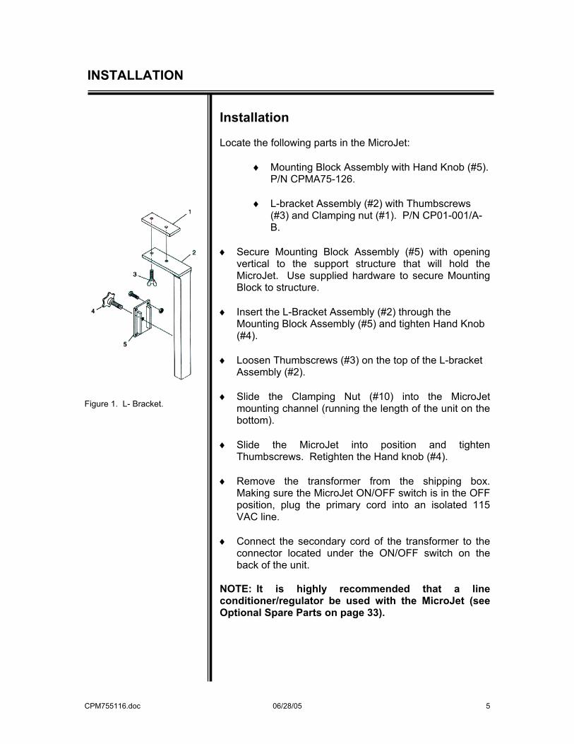
Figure 1. L- Bracket.
Installation Locate the following parts in the MicroJet:
♦ Mounting Block Assembly with Hand Knob (#5). P/N CPMA75-126.
♦ L-bracket Assembly (#2) with Thumbscrews
(#3) and Clamping nut (#1). P/N CP01-001/A-B.
♦ Secure Mounting Block Assembly (#5) with opening
vertical to the support structure that will hold the MicroJet. Use supplied hardware to secure Mounting Block to structure.
♦ Insert the L-Bracket Assembly (#2) through the
Mounting Block Assembly (#5) and tighten Hand Knob (#4).
♦ Loosen Thumbscrews (#3) on the top of the L-bracket
Assembly (#2). ♦ Slide the Clamping Nut (#10) into the MicroJet
mounting channel (running the length of the unit on the bottom).
♦ Slide the MicroJet into position and tighten
Thumbscrews. Retighten the Hand knob (#4). ♦ Remove the transformer from the shipping box.
Making sure the MicroJet ON/OFF switch is in the OFF position, plug the primary cord into an isolated 115 VAC line.
♦ Connect the secondary cord of the transformer to the
connector located under the ON/OFF switch on the back of the unit.
NOTE: It is highly recommended that a line conditioner/regulator be used with the MicroJet (see Optional Spare Parts on page 33).
CPM755116.doc 06/28/05 6
OPERATION
Operation The MicroJet ink coder is not shipped with the ink container in position. Ink is shipped separately in its own shipping case. Note: "USE OF ANY INK NOT CONFORMING TO LOVESHAW'S SPECIFICATIONS WILL VOID THE UNIT WARRANTY."
♦ The ink container compartment is located in the lower half of the unit. It is accessible by lifting the larger side-hinged lid.
♦ Stand ink container in the unit with the angled
side facing the on/off switch and flat side is facing the valves.
♦ Twist off plastic shipping cap and set aside.
♦ The brass cap insert found inside the MicroJet
has a large pin (air) and a small pin (ink) that must be inserted into the container. Be sure the pins are in their proper positions (air pin on top, next to the label) before penetrating the membranes.
♦ Press brass cap insert into position and tighten
the brass screw cap. (Brass insert and cap must remain flat while torque is applied.
♦ Lay the ink container flat in unit so that the cap
and bottle-neck are forward in the compartment.
♦ Check for proper seal of brass cap and insert.
(Slowly invert container while checking).
♦ Turn the unit on and allow the pressure to build (10 seconds).
♦ To avoid printing while setting up, avoid passing
anything in front of unit that may accidentally trip the photocell.
CPM755116.doc 06/28/05 7
OPERATION
Figure 2. Unit start-up.
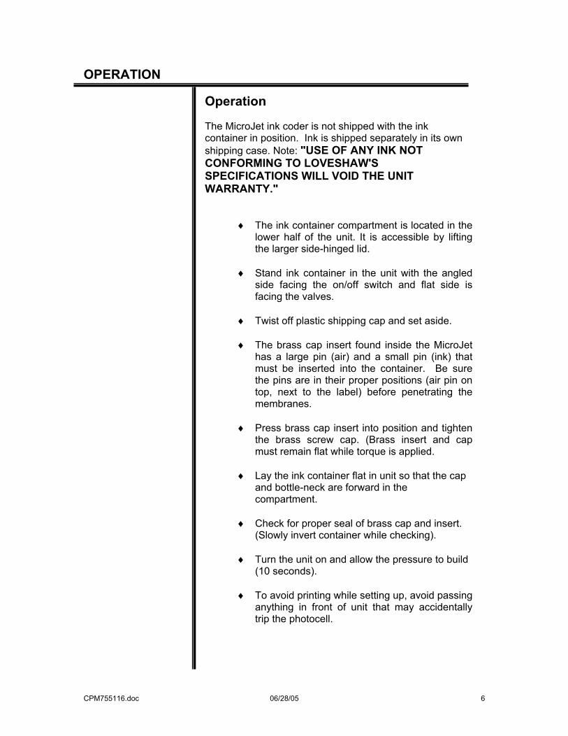
♦ With an open container in front of the nozzle plate,
hold the purge switch down until ink reaches the nozzle plate and streams of ink result. While purging, hold the lid in a vertical position (see Fig. 2).
♦ Backflush any nozzle that does not give a straight
and steady stream of ink (see Figure 26 on page 31).
♦ The MicroJet unit is now ready to be
programmed to print. ♦ The LCD screen will show the software version and
the word “LOCKED”. Unlock the MicroJet by entering the unlock code: 5863434. When the correct unlock code has been entered, the LCD screen will show a test message, be blank, or show the last message printed.
♦ To enter your message, press MSG key. There will
be a blinking cursor on the upper left side of the LCD screen.
♦ Press the character keys to create your message.
It will show up in the LCD screen. Remember that a message line is 39 characters maximum. Spaces are included in the character count.
♦ Use the INCR, DECR keys to move the cursor to
make any necessary corrections as you prepare your message.
♦ When your message is complete, press ENTER
and your message will print after a box passing in front of the unit has activated the photocell.
PLEASE NOTE…THE MICROJET IS DESIGNED TO PRINT WHILE MOUNTED IN A HORIZONTAL POSITION ONLY. FOR OPTIMUM PERFORMANCE, DO NOT ATTEMPT TO MOUNT IN A VERTICAL POSITION.
CPM755116.doc 06/28/05 8
KEYBOARD and DISPLAY
Printing The MicroJet will not print when a feature is being used. The ENTER key should always be pressed when finished with a feature, or printing can’t occur. If there is any doubt about this, just press ENTER a few more times. (Some features require the sequence MENU, ENTER to exit).
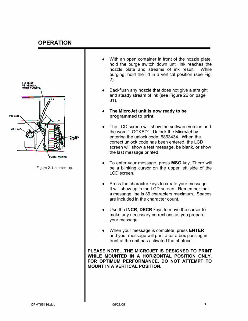
NOTE: BOLD CAPITAL LETTERS USED IN THE TEXT OF THIS MANUAL DENOTES A KEY ON THE KEYPAD.
Figure 3. Keyboard and Display.
Keyboard and Display The keyboard and display are used to “set-up” the MicroJet to print any desired message. The keyboard is used mostly for entering messages to be printed, but is also used to adjust MicroJet features. To use any MicroJet features, including entering or changing print messages; a “command” key must be used. The keyboard has various kinds of keys on it, including the command keys.
CPM755116.doc 06/28/05 9
KEYBOARD and DISPLAY
Character Keys The top six rows of the keyboard contain all the characters in the alphabet, numbers and various figure characters. SPACE On the bottom of the keyboard is the space key; it is like a typewriter space key and is used to put blanks into printed messages. Control Keys There are six control keys among the keys on the bottom two rows of the keyboard. UPPER KEY When the upper key is pressed and held down, and then one of the letter keys with a “figure” shown on the key top is pressed, and then both keys released, the figure character is entered instead of the letter. These figure characters are used when entering print messages. FUNC When the func key is pressed and held down, and then one of several letter keys is pressed, and then both are released, special “functions” are activated; these functions are only used when entering print messages, ENTER Pressed to “enter” a number or command when adjusting MicroJet features. DEL Removes characters or numbers. INCR Used when entering numbers and print messages. DECR Used when entering numbers and print messages.
CPM755116.doc 06/28/05 10
KEYBOARD and DISPLAY
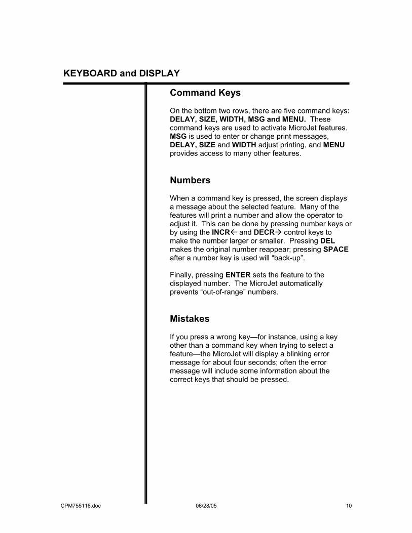
Command Keys On the bottom two rows, there are five command keys: DELAY, SIZE, WIDTH, MSG and MENU. These command keys are used to activate MicroJet features. MSG is used to enter or change print messages, DELAY, SIZE and WIDTH adjust printing, and MENU provides access to many other features. Numbers When a command key is pressed, the screen displays a message about the selected feature. Many of the features will print a number and allow the operator to adjust it. This can be done by pressing number keys or by using the INCR and DECR control keys to make the number larger or smaller. Pressing DEL makes the original number reappear; pressing SPACE after a number key is used will “back-up”. Finally, pressing ENTER sets the feature to the displayed number. The MicroJet automatically prevents “out-of-range” numbers. Mistakes If you press a wrong key—for instance, using a key other than a command key when trying to select a feature—the MicroJet will display a blinking error message for about four seconds; often the error message will include some information about the correct keys that should be pressed.
CPM755116.doc 06/28/05 11
Keyboard and Display
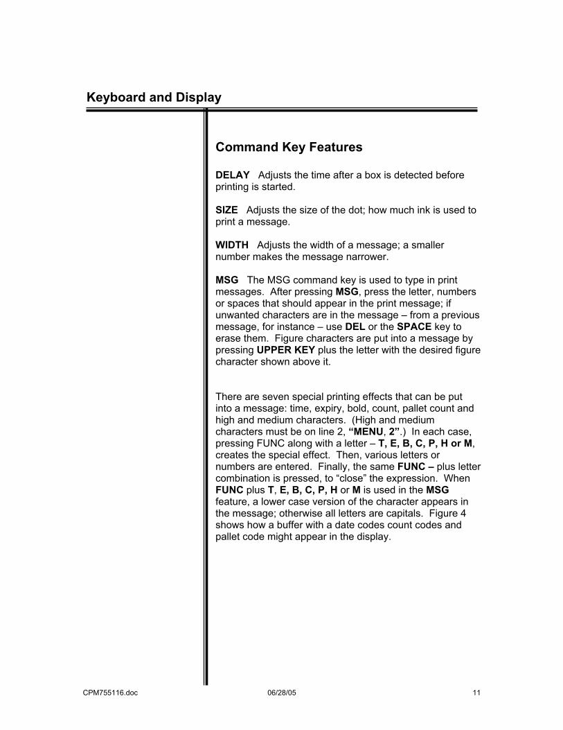
Command Key Features DELAY Adjusts the time after a box is detected before printing is started. SIZE Adjusts the size of the dot; how much ink is used to print a message. WIDTH Adjusts the width of a message; a smaller number makes the message narrower. MSG The MSG command key is used to type in print messages. After pressing MSG, press the letter, numbers or spaces that should appear in the print message; if unwanted characters are in the message – from a previous message, for instance – use DEL or the SPACE key to erase them. Figure characters are put into a message by pressing UPPER KEY plus the letter with the desired figure character shown above it. There are seven special printing effects that can be put into a message: time, expiry, bold, count, pallet count and high and medium characters. (High and medium characters must be on line 2, “MENU, 2”.) In each case, pressing FUNC along with a letter – T, E, B, C, P, H or M, creates the special effect. Then, various letters or numbers are entered. Finally, the same FUNC – plus letter combination is pressed, to “close” the expression. When FUNC plus T, E, B, C, P, H or M is used in the MSG feature, a lower case version of the character appears in the message; otherwise all letters are capitals. Figure 4 shows how a buffer with a date codes count codes and pallet code might appear in the display.
CPM755116.doc 06/28/05 12
Keyboard and Display
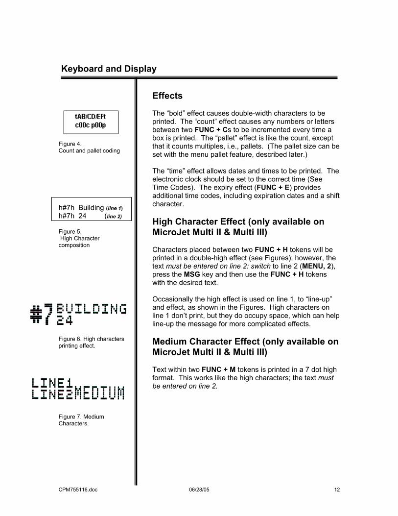
Figure 4. Count and pallet coding h#7h Building (line 1) h#7h 24 (line 2) Figure 5. High Character composition
Figure 6. High characters printing effect.
Figure 7. Medium Characters.
Effects The “bold” effect causes double-width characters to be printed. The “count” effect causes any numbers or letters between two FUNC + Cs to be incremented every time a box is printed. The “pallet” effect is like the count, except that it counts multiples, i.e., pallets. (The pallet size can be set with the menu pallet feature, described later.) The “time” effect allows dates and times to be printed. The electronic clock should be set to the correct time (See Time Codes). The expiry effect (FUNC + E) provides additional time codes, including expiration dates and a shift character. High Character Effect (only available on MicroJet Multi II & Multi III) Characters placed between two FUNC + H tokens will be printed in a double-high effect (see Figures); however, the text must be entered on line 2: switch to line 2 (MENU, 2), press the MSG key and then use the FUNC + H tokens with the desired text. Occasionally the high effect is used on line 1, to “line-up” and effect, as shown in the Figures. High characters on line 1 don’t print, but they do occupy space, which can help line-up the message for more complicated effects. Medium Character Effect (only available on MicroJet Multi II & Multi III) Text within two FUNC + M tokens is printed in a 7 dot high format. This works like the high characters; the text must be entered on line 2.
CPM755116.doc 06/28/05 13
Keyboard and Display
ZÄHLEN c024c Figure 8. Non-English Character before selection ZÆHLEN c024c Figure 9. Non-English Character after Selection
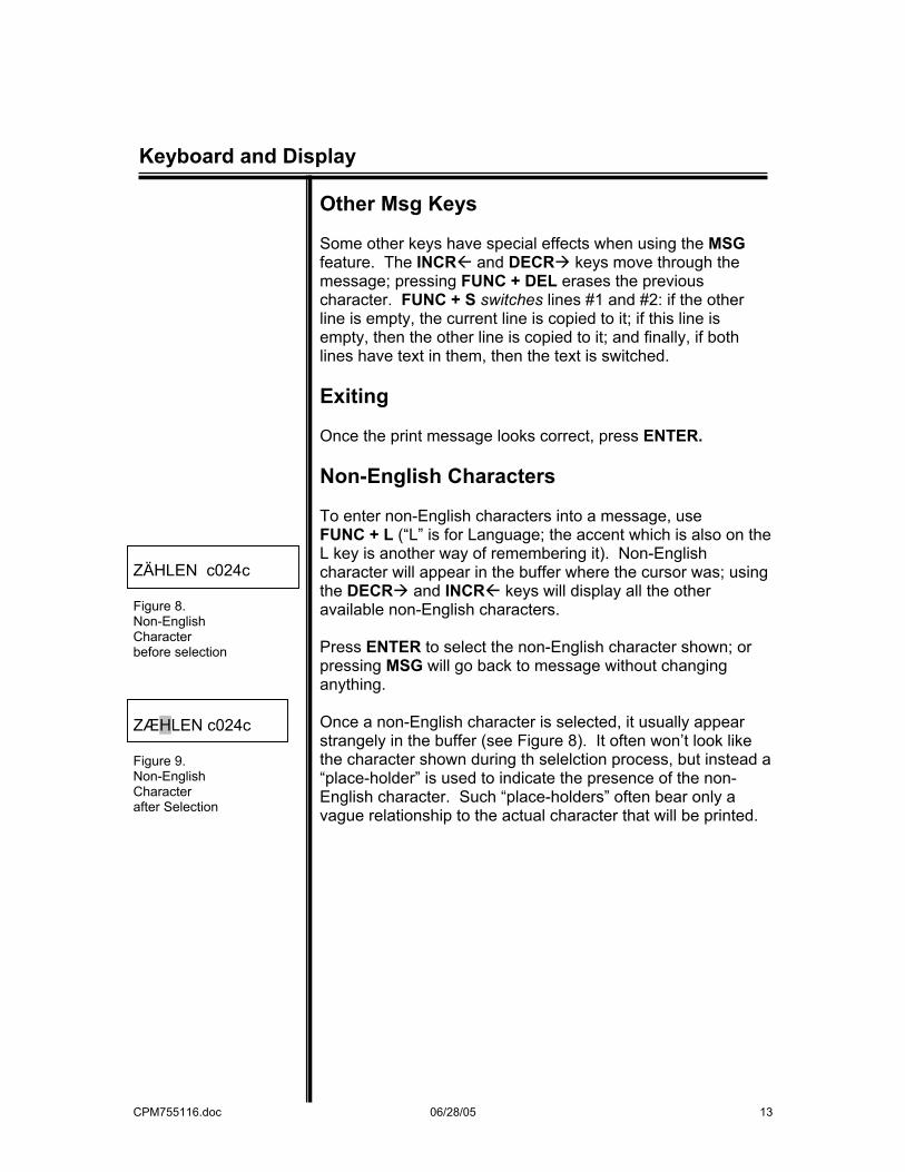
Other Msg Keys Some other keys have special effects when using the MSG feature. The INCR and DECR keys move through the message; pressing FUNC + DEL erases the previous character. FUNC + S switches lines #1 and #2: if the other line is empty, the current line is copied to it; if this line is empty, then the other line is copied to it; and finally, if both lines have text in them, then the text is switched. Exiting Once the print message looks correct, press ENTER. Non-English Characters To enter non-English characters into a message, use FUNC + L (“L” is for Language; the accent which is also on the L key is another way of remembering it). Non-English character will appear in the buffer where the cursor was; using the DECR and INCR keys will display all the other available non-English characters. Press ENTER to select the non-English character shown; or pressing MSG will go back to message without changing anything. Once a non-English character is selected, it usually appear strangely in the buffer (see Figure 8). It often won’t look like the character shown during th selelction process, but instead a “place-holder” is used to indicate the presence of the non-English character. Such “place-holders” often bear only a vague relationship to the actual character that will be printed.
CPM755116.doc 06/28/05 14
Keyboard and Display
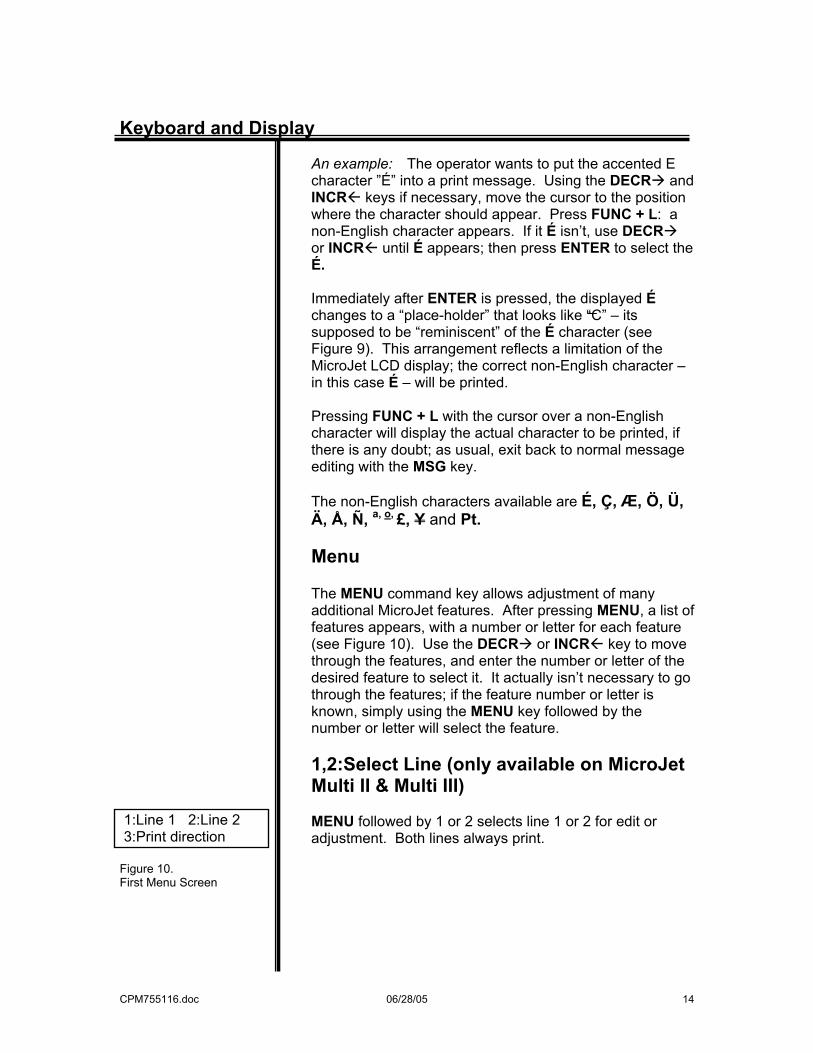
1:Line 1 2:Line 2 3:Print direction Figure 10. First Menu Screen
An example: The operator wants to put the accented E character ”É” into a print message. Using the DECR and INCR keys if necessary, move the cursor to the position where the character should appear. Press FUNC + L: a non-English character appears. If it É isn’t, use DECR or INCR until É appears; then press ENTER to select the É. Immediately after ENTER is pressed, the displayed É changes to a “place-holder” that looks like “C” – its supposed to be “reminiscent” of the É character (see Figure 9). This arrangement reflects a limitation of the MicroJet LCD display; the correct non-English character – in this case É – will be printed. Pressing FUNC + L with the cursor over a non-English character will display the actual character to be printed, if there is any doubt; as usual, exit back to normal message editing with the MSG key. The non-English characters available are É, Ç, Æ, Ö, Ü, Ä, Å, Ñ, a, o, £, Y and Pt. Menu The MENU command key allows adjustment of many additional MicroJet features. After pressing MENU, a list of features appears, with a number or letter for each feature (see Figure 10). Use the DECR or INCR key to move through the features, and enter the number or letter of the desired feature to select it. It actually isn’t necessary to go through the features; if the feature number or letter is known, simply using the MENU key followed by the number or letter will select the feature. 1,2:Select Line (only available on MicroJet Multi II & Multi III) MENU followed by 1 or 2 selects line 1 or 2 for edit or adjustment. Both lines always print.
CPM755116.doc
Menu
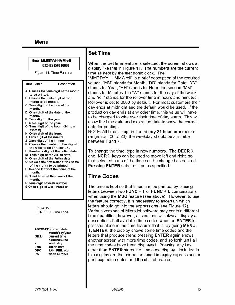
Figure 11. Time Feature Figure 12 FUNC + T Time code AB/CD/EF current date month/day/year GH:IJ current time hour:minutes K week day LMN Julian date OPQ JAN, FEB, etc… RS week number
Set Time When the Set time feature is selected, the screen shows a display like that in Figure 11. The numbers are the current time as kept by the electronic clock. The “MMDDYYHHMMWroll” is a brief description of the required values: “MM” stands for Month, “DD” stands for Date, “YY” stands for Year, “HH” stands for Hour, the second “MM” stands for Minutes, the ”W” stands for the day of the week, and “roll” stands for the rollover time in hours and minutes. Rollover is set to 0000 by default. For most customers their day ends at midnight and the default would be used. If the production day ends at any other time, this value will have to be changed to whatever their time of day starts. This will allow the time data and expiration data to show the correct date for printing. NOTE: All time is kept in the military 24-hour form (hour’s range from 00 to 23); the weekday should be a number between 1 and 7. To change the time, type in new numbers. The DECR and INCR keys can be used to move left and right, so that selected parts of the time can be changed as desired. Pressing ENTER sets the time as specified. Time Codes The time is kept so that times can be printed, by placing letters between two FUNC + T or FUNC + E combinations when using the MSG feature (see above). However, to use the feature correctly, it is necessary to ascertain which letters should go into the expressions (see Figure 12). Various versions of MicroJet software may contain different time quantities; however, all versions will always display a description of all available time codes when an ENTER is pressed alone in the time feature: that is, by going MENU, T, ENTER, the display shows some time codes and the letters that produce them; pressing ENTER again shows another screen with more time codes; and so forth until all the time codes have been displayed. Pressing any key other than ENTER stops the time code display. Included in this display are the characters used in expiry expressions to print expiration dates and the shift character.
Time Letter Description _______________________________ A Causes the tens digit of the month to be printed. B Causes the units digit of the month to be printed. C Tens digit of the date of the month. D Ones digit of the date of the month. E Tens digit of the year. F Ones digit of the year. G Tens digit of the hour (24 hour system). H Ones digit of the hour. I Tens digit of the minute. J Ones digit of the minute. K Causes the number of the day of the week to be printed(1..7). L Hundreds digit of the Julian date. M Tens digit of the Julian date. N Ones digit of the Julian date. O Causes the first letter of the name of the month to be printed. P Second letter of the name of the month. Q Third letter of the name of the month. R Tens digit of week number S Ones digit of week number
06/28/05 15
CPM755116.doc 06/28/05 16
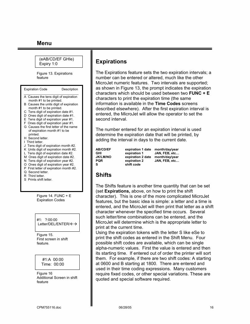
Menu (eAB/CD/EF GHIe) Expiry 1:0 Figure 13. Expirations feature Figure 14. FUNC + E Expiration Codes #1: ?:00:00 Letter/DEL/ENTER/ Figure 15. First screen in shift feature. #1:A 00:00 Time: 00:00 Figure 16 Additional Screen in shift feature
Expirations The Expirations feature sets the two expiration intervals; a number can be entered or altered, much like the other MicroJet numeric features. Two intervals are supported; as shown in Figure 13, the prompt indicates the expiration characters which should be used between two FUNC + E characters to print the expiration time (the same information is available in the Time Codes screens described elsewhere). After the first expiration interval is entered, the MicroJet will allow the operator to set the second interval. The number entered for an expiration interval is used determine the expiration date that will be printed, by adding the interval in days to the current date. AB/CD/EF expiration 1 date month/day/year GHI expiration 1 JAN, FEB, etc… JK/LM/NO expiration 2 date month/day/year PQR expiration 2 JAN, FEB, etc… S shift code Shifts The Shifts feature is another time quantity that can be set (set Expirations, above, on how to print the shift character). This is one of the more complicated MicroJet features, but the basic idea is simple: a letter and a time is entered, and the MicroJet will then print that letter as a shift character whenever the specified time occurs. Several such letter/time combinations can be entered, and the MicroJet will determine which is the appropriate letter to print at the current time. Using the expiration tokens with the letter S like eSe to print the shift codes as entered in the Shift Menu. Four possible shift codes are available, which can be single alpha-numeric values. First the value is entered and then its starting time. If entered out of order the printer will sort them. For example, if there are two shift codes: A starting at 0600 and B starting at 1800. There are entered and used in their time coding expressions. Many customers require fixed codes, or other special variations. These are quoted and special software required.
Expiration Code Description ______________________________ A Causes the tens digit of expiration month #1 to be printed. B Causes the units digit of expiration month #1 to be printed. C Tens digit of expiration date #1. D Ones digit of expiration date #1. E Tens digit of expiration year #1. F Ones digit of expiration year #1. G Causes the first letter of the name of expiration month #1 to be printed. H Second letter. I Third letter. J Tens digit of expiration month #2. K Units digit of expiration month #2. L Tens digit of expiration date #2. M Ones digit of expiration date #2. N Tens digit of expiration year #2. O Ones digit of expiration year #2. P First letter of expiration month #2. Q Second letter. R Third letter. S Prints shift letter.
CPM755116.doc 06/28/05 17
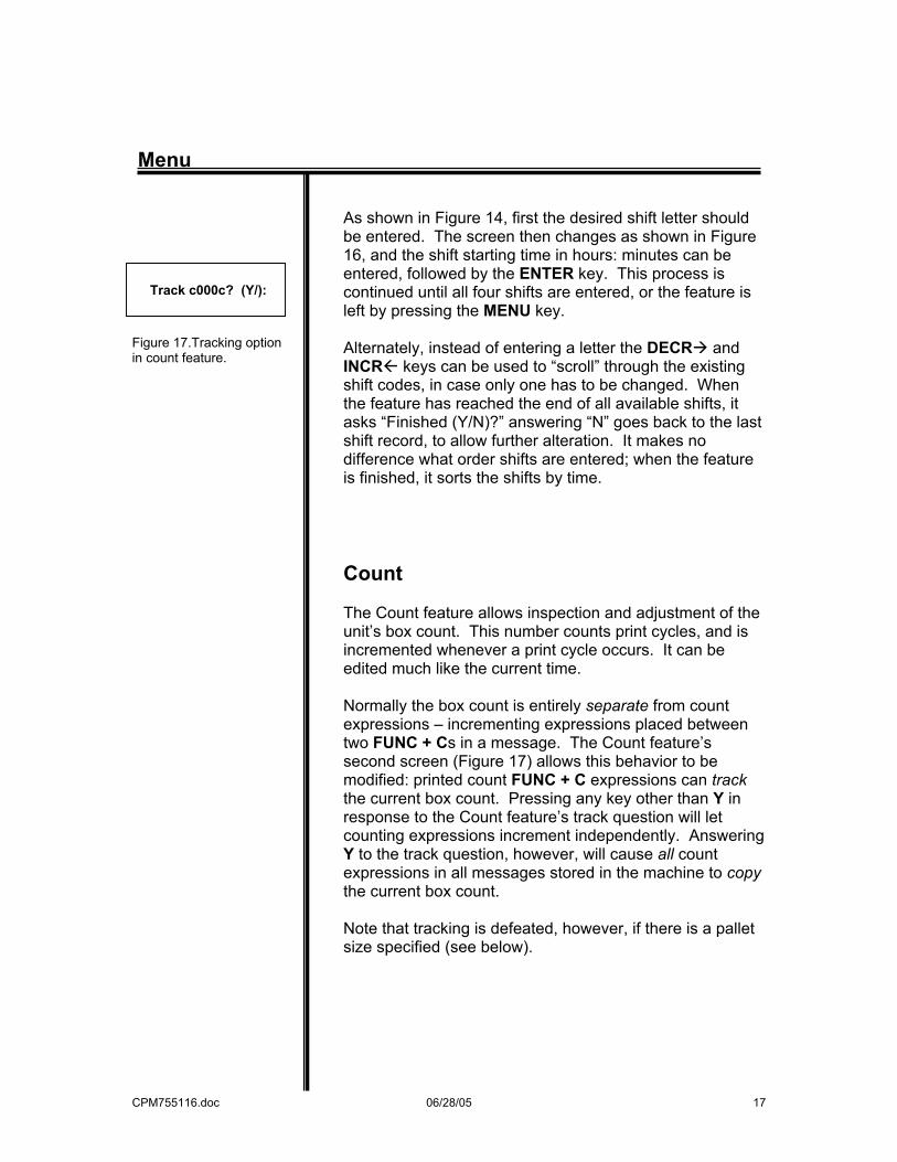
Menu Track c000c? (Y/): Figure 17.Tracking option in count feature.
As shown in Figure 14, first the desired shift letter should be entered. The screen then changes as shown in Figure 16, and the shift starting time in hours: minutes can be entered, followed by the ENTER key. This process is continued until all four shifts are entered, or the feature is left by pressing the MENU key. Alternately, instead of entering a letter the DECR and INCR keys can be used to “scroll” through the existing shift codes, in case only one has to be changed. When the feature has reached the end of all available shifts, it asks “Finished (Y/N)?” answering “N” goes back to the last shift record, to allow further alteration. It makes no difference what order shifts are entered; when the feature is finished, it sorts the shifts by time.
Count The Count feature allows inspection and adjustment of the unit’s box count. This number counts print cycles, and is incremented whenever a print cycle occurs. It can be edited much like the current time. Normally the box count is entirely separate from count expressions – incrementing expressions placed between two FUNC + Cs in a message. The Count feature’s second screen (Figure 17) allows this behavior to be modified: printed count FUNC + C expressions can track the current box count. Pressing any key other than Y in response to the Count feature’s track question will let counting expressions increment independently. Answering Y to the track question, however, will cause all count expressions in all messages stored in the machine to copy the current box count. Note that tracking is defeated, however, if there is a pallet size specified (see below).
CPM755116.doc 06/28/05 18
Menu
Change Message Selects a message from storage. There are up to 168 variable length messages which can be stored in the MicroJet; the CHANGE MESSAGE feature selects which message can be edited and/or be printed. The number displayed when the feature is selected is the number of the current message – the one that will be printed now. When this number is changed, either by pressing numbers keys or using the DECR and INCR keys (that is, just like other numeric quantities, such as DELAY or WIDTH) the current print message disappears, but remains saved in memory, and is replaced by blanks or by a previously composed message. Using the CHANGE MESSAGE feature and selecting its number can always retrieve the original message Message Review Within the CHANGE MESSAGE feature, the operator can view the various messages stored in memory. This is convenient if the number of a particular message is uncertain. Entering? (Or D for “Display”—the letter on the ? key) in the CHANGE MESSAGE feature (that is, instead of a number or using the DECR or INCR keys) brings up message review: the text of the current message is shown, and the number of the message is displayed in the lower right hand corner of the screen. Pressing the DECR and INCR keys will “move” through the various messages, and show one after another. Pressing ENTER selects the current message shown, and returns to the normal CHANGE MESSAGE screen, where pressing ENTER again will select the message.
CPM755116.doc 06/28/05 19
Menu
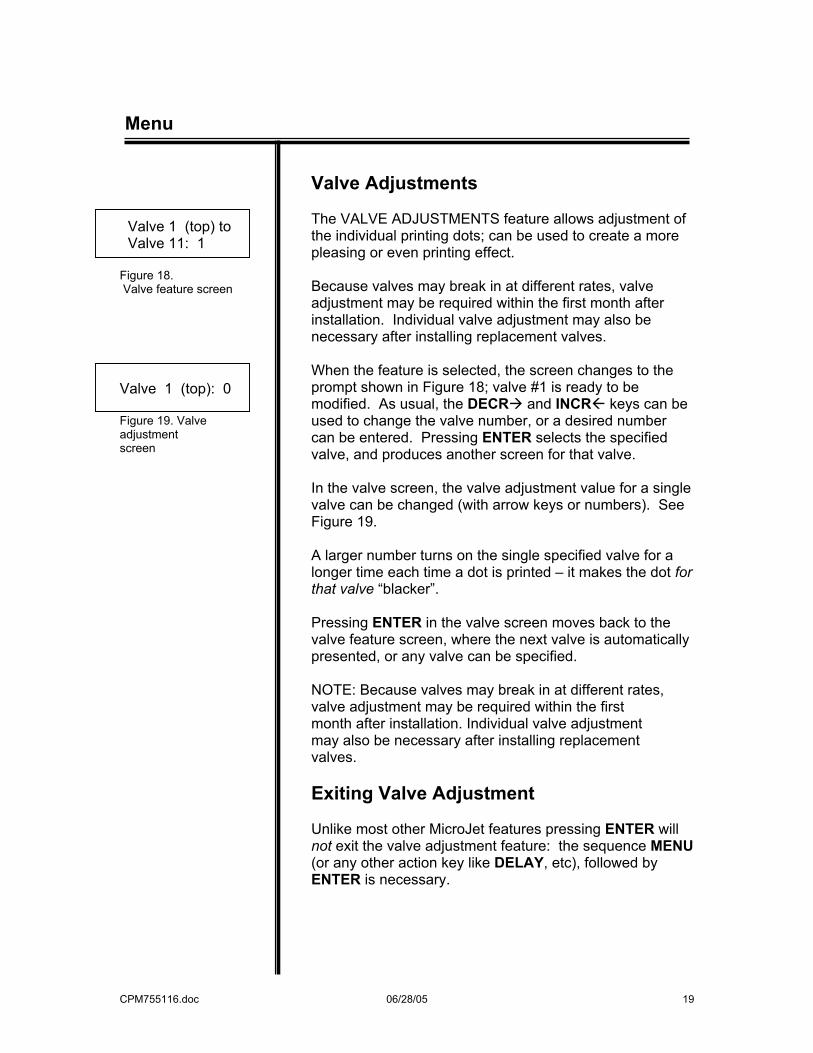
Valve 1 (top) to Valve 11: 1 Figure 18. Valve feature screen Valve 1 (top): 0 Figure 19. Valve adjustment screen
Valve Adjustments The VALVE ADJUSTMENTS feature allows adjustment of the individual printing dots; can be used to create a more pleasing or even printing effect. Because valves may break in at different rates, valve adjustment may be required within the first month after installation. Individual valve adjustment may also be necessary after installing replacement valves. When the feature is selected, the screen changes to the prompt shown in Figure 18; valve #1 is ready to be modified. As usual, the DECR and INCR keys can be used to change the valve number, or a desired number can be entered. Pressing ENTER selects the specified valve, and produces another screen for that valve. In the valve screen, the valve adjustment value for a single valve can be changed (with arrow keys or numbers). See Figure 19. A larger number turns on the single specified valve for a longer time each time a dot is printed – it makes the dot for that valve “blacker”. Pressing ENTER in the valve screen moves back to the valve feature screen, where the next valve is automatically presented, or any valve can be specified. NOTE: Because valves may break in at different rates, valve adjustment may be required within the first month after installation. Individual valve adjustment may also be necessary after installing replacement valves. Exiting Valve Adjustment Unlike most other MicroJet features pressing ENTER will not exit the valve adjustment feature: the sequence MENU (or any other action key like DELAY, etc), followed by ENTER is necessary.
CPM755116.doc 06/28/05 20
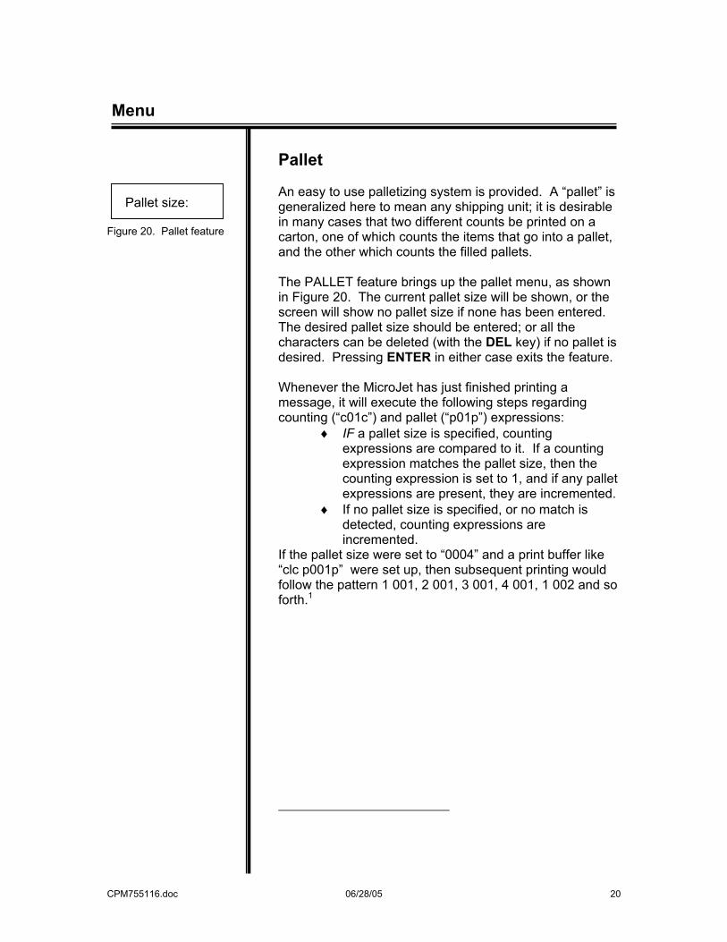
Menu Pallet size: Figure 20. Pallet feature
Pallet An easy to use palletizing system is provided. A “pallet” is generalized here to mean any shipping unit; it is desirable in many cases that two different counts be printed on a carton, one of which counts the items that go into a pallet, and the other which counts the filled pallets. The PALLET feature brings up the pallet menu, as shown in Figure 20. The current pallet size will be shown, or the screen will show no pallet size if none has been entered. The desired pallet size should be entered; or all the characters can be deleted (with the DEL key) if no pallet is desired. Pressing ENTER in either case exits the feature. Whenever the MicroJet has just finished printing a message, it will execute the following steps regarding counting (“c01c”) and pallet (“p01p”) expressions:
♦ IF a pallet size is specified, counting expressions are compared to it. If a counting expression matches the pallet size, then the counting expression is set to 1, and if any pallet expressions are present, they are incremented.
♦ If no pallet size is specified, or no match is detected, counting expressions are incremented.
If the pallet size were set to “0004” and a print buffer like “clc p001p” were set up, then subsequent printing would follow the pattern 1 001, 2 001, 3 001, 4 001, 1 002 and so forth.1
CPM755116.doc 06/28/05 21
Menu
____________________________ 1 Pallet counting is actually somewhat more sophisticated than this brief summary suggest. After a message is printed, the software checks the value of the counting expression (“c002c”) furthest to the right in the message and compares it with the pallet expression specified by the operator. If there is no match, then the counting expressions get incremented as usual. If the right most counting expression matches the operator’s specified maximum value, then all incrementing expressions in the buffer are set to 1 (alphabetic expressions are set to “cAAAc”) and any pallet expressions (“p003p”) are incremented. Thus the pallet expression slowly count the pallets, while the counting expressions more rapidly count the number of items within the current pallet. No arithmetic comparison is made between counting expressions and the specified maximum. If the counting expression starts with a value larger than the specified maximum it will not be reset. Also, pallet comparison is conducted in a special way:
• Pallet count comparison starts on the right. The right most character in the right most counting expression is compared with the right most character in the specified pallet count. Then the next character to the left is compared, and so forth. It there is more than one counting expression in a palletized buffer, only the right most one is used for comparison.
• Excess is discarded. During the comparison, if the left side of either expression is reached without a mismatch, the software assumes a match has occurred. Thus a maximum of “11” will match a counting expression of “c0011c”, “c111c” and so forth. The reverse is also true: a maximum of “123” will match the counting expressions “c23c” and “c3c”/
• Special characters are ignored. Any effect tokens within the counting expression (bold for instance) are ignored for purposes of comparison.
CPM755116.doc 06/28/05 22
Menu 1:ENGL 2:ITAL 3:DEUT 4:FRAN Figure 21. Language menu
Select Language The SELECT LANGUAGE feature determines the language in which MicroJet menus and other informative screens will be displayed. The feature works like the MENU feature itself: use the DECR and INCR keys to move through the available languages, and then press the appropriate number of character for the desired language. Figure 21 shows the beginning of the language menu; pressing the arrow keys will “scroll” to show more of it. Available languages are English, Italian, German, French, Spanish and Dutch. The languages are usually indicated on the menu with an abbreviation in the original language (i.e., “ESPA” for Spanish) to facilitate recognition by language speakers. Other The OTHER menu selection provides access to various little used and maintenance features of the printer; the contents of the menu may change from version to version of the software. One OTHER selection is “Slash”: the MicroJet normally prints the zero character with a slash through it to distinguish it from the letter “O”. The SLASH feature optionally changes this behavior so that zeros are rendered without a slash and look like the letter “O”, during printing and on the MicroJet display. The Character Space adjust the amount of hidden dots between the characters; whereas the Space Width adjust the space “ “ character itself. Invert The INVERT menu selection provides the customer the capability of printing upside down. This command and reversing the direction will boxes to be loaded in a bottom-inserted application.
CPM755116.doc 06/28/05 23
Purge
Purge “Purging” is the process of cleaning the print heads by running ink through them (a container should be arranged to catch run-off). There are various ways to clean and purge a printhead, including the MicroJet’s FUNC + A then P command. In the ready to print display (the normal operating display, reachable via MENU, ENTER if necessary), pressing and holding FUNC and then pressing the letter A, P will start the purge. The purge actually starts when the P key is released, and continues until any other key is pressed and released. For a controlled effect, press and release FUNC + A key once, then and press hold P down again, releasing it at the precise moment the purge should stop. FUNC A also provides a dampen selection for breaking in new valves for production FUNC A + D. FUNC A + A is a print trigger which prints all lines every time A is pressed. This is useful when you want to print with the photocells blocked. 666SLAM To clear the MicroJet – erase all stored print messages and settings. Turn the unit off, press and hold the number 6, turn the unit on. Wait about a second, release the 6, then press “66SLAM”. If any error is made in typing the characters, the memory clear does not occur. The procedure should only be necessary when an unusual electrical disturbance has corrupted the unit’s memory. Command “Jumping” When various MicroJet features are being adjusted, pressing one of the command keys (DELAY, WIDTH, etc.) will usually “exit” the current feature and go immediately to the requested feature.
CPM755116.doc 06/28/05 24
Maintenance SHORT TERM Up to 2 days Shutdown Start up LONG TERM Greater than 2 days Shutdown Start up DAILY Greater than 3 weeks
Maintenance A few simple procedures will keep the MicroJet in perfect working order. General Maintenance To insure continuous trouble-free operation, these simple steps should be followed: No maintenance necessary. Wipe the nozzle plate with a damp cloth. Turn the unit on and print. Purge if necessary. Before shutting the unit down for periods longer than 48 hours, wipe the nozzle plate with a wet cloth. Coat the nozzle with a small amount of petroleum jelly. Wipe the nozzle plate to remove the petroleum jelly. Purge and wipe the nozzle until all petroleum jelly is wiped away, and all nozzles are purging straight streams of ink. Repeat as necessary until all nozzles are purging. Wipe the photocells with a dampened cloth. For extended down times (longer than three weeks), the unit should be flushed with Loveshaw’s Valve Pre-Conditioning Fluid (see page 33 for part number). This fluid prevents ink from drying in the plastic tubes on the unit. When restarting the unit, be sure to flush out all conditioner with ink (ink should run pure black), before beginning to print.
CPM755116.doc 06/28/05 25
General Maintenance
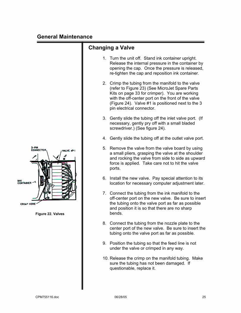
Figure 22. Valves
Changing a Valve
1. Turn the unit off. Stand ink container upright. Release the internal pressure in the container by opening the cap. Once the pressure is released, re-tighten the cap and reposition ink container.
2. Crimp the tubing from the manifold to the valve
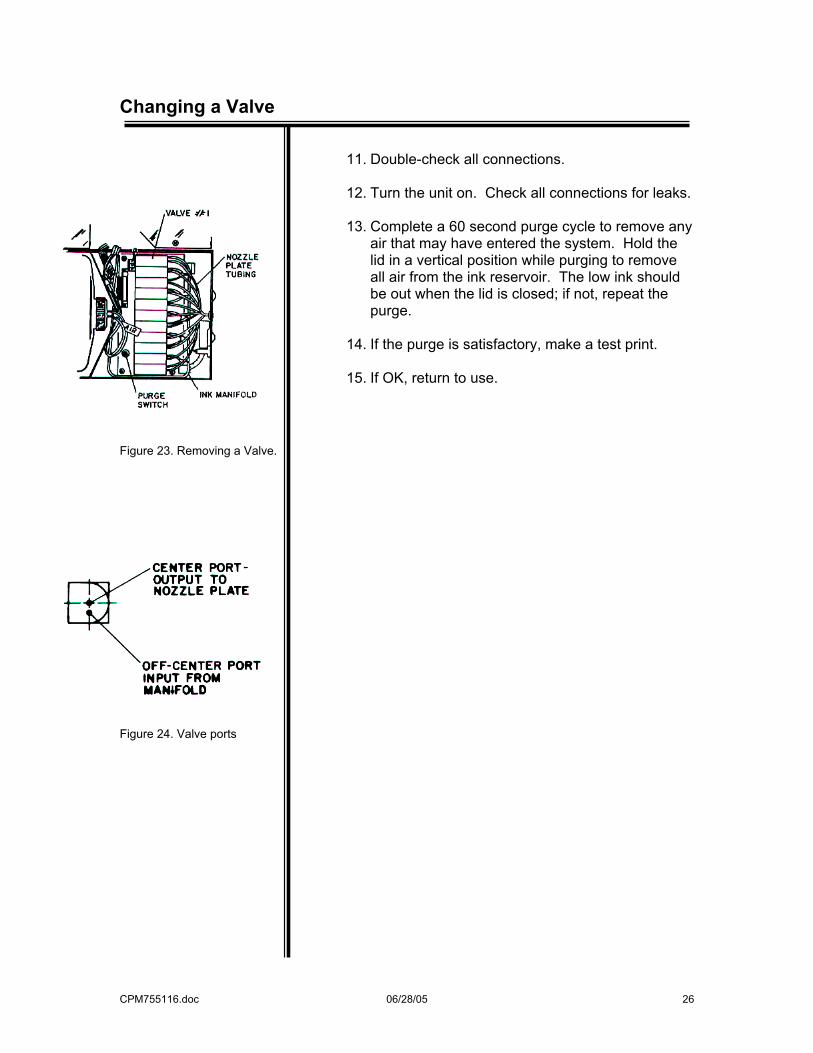
(refer to Figure 23) (See MicroJet Spare Parts Kits on page 33 for crimper). You are working with the off-center port on the front of the valve (Figure 24). Valve #1 is positioned next to the 3 pin electrical connector.
3. Gently slide the tubing off the inlet valve port. (If
necessary, gently pry off with a small bladed screwdriver.) (See figure 24).
4. Gently slide the tubing off at the outlet valve port.
5. Remove the valve from the valve board by using
a small pliers, grasping the valve at the shoulder and rocking the valve from side to side as upward force is applied. Take care not to hit the valve ports.
6. Install the new valve. Pay special attention to its
location for necessary computer adjustment later.
7. Connect the tubing from the ink manifold to the off-center port on the new valve. Be sure to insert the tubing onto the valve port as far as possible and position it is so that there are no sharp bends.
8. Connect the tubing from the nozzle plate to the
center port of the new valve. Be sure to insert the tubing onto the valve port as far as possible.
9. Position the tubing so that the feed line is not
under the valve or crimped in any way.
10. Release the crimp on the manifold tubing. Make sure the tubing has not been damaged. If questionable, replace it.
CPM755116.doc 06/28/05 26
Changing a Valve
Figure 23. Removing a Valve.
Figure 24. Valve ports
11. Double-check all connections.
12. Turn the unit on. Check all connections for leaks.
13. Complete a 60 second purge cycle to remove any air that may have entered the system. Hold the lid in a vertical position while purging to remove all air from the ink reservoir. The low ink should be out when the lid is closed; if not, repeat the purge.
14. If the purge is satisfactory, make a test print.
15. If OK, return to use.
CPM755116.doc 06/28/05 27
Removing/Replacing Valve Board
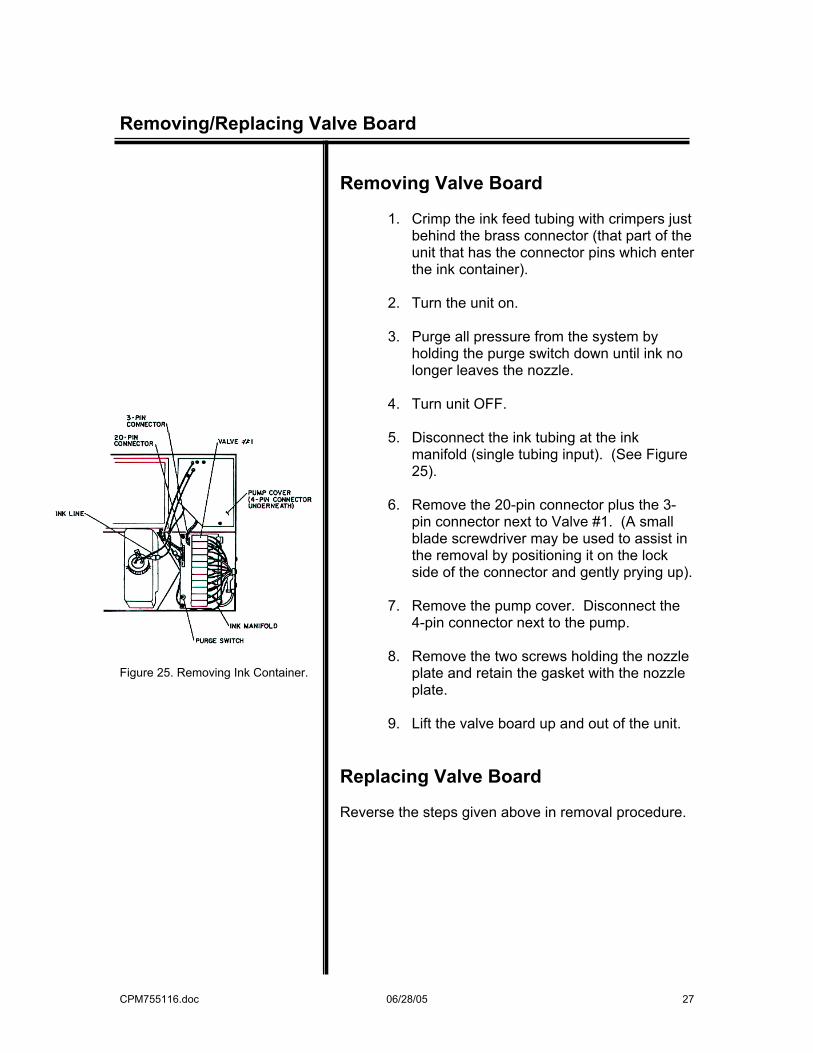
Figure 25. Removing Ink Container.
Removing Valve Board
1. Crimp the ink feed tubing with crimpers just behind the brass connector (that part of the unit that has the connector pins which enter the ink container).
2. Turn the unit on.
3. Purge all pressure from the system by
holding the purge switch down until ink no longer leaves the nozzle.
4. Turn unit OFF.
5. Disconnect the ink tubing at the ink
manifold (single tubing input). (See Figure 25).
6. Remove the 20-pin connector plus the 3-
pin connector next to Valve #1. (A small blade screwdriver may be used to assist in the removal by positioning it on the lock side of the connector and gently prying up).
7. Remove the pump cover. Disconnect the
4-pin connector next to the pump.
8. Remove the two screws holding the nozzle plate and retain the gasket with the nozzle plate.
9. Lift the valve board up and out of the unit.
Replacing Valve Board Reverse the steps given above in removal procedure.
CPM755116.doc 06/28/05 28
Ink Container Replacement
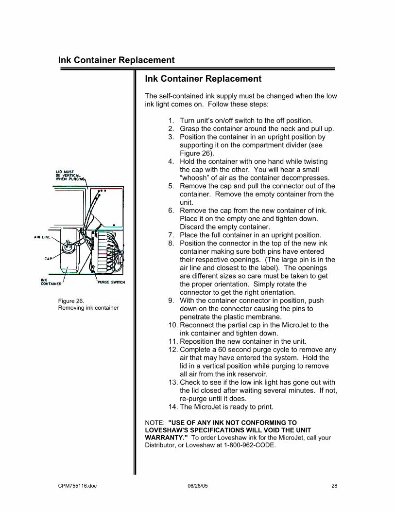
Figure 26. Removing ink container
Ink Container Replacement The self-contained ink supply must be changed when the low ink light comes on. Follow these steps:
1. Turn unit’s on/off switch to the off position. 2. Grasp the container around the neck and pull up. 3. Position the container in an upright position by
supporting it on the compartment divider (see Figure 26).
4. Hold the container with one hand while twisting the cap with the other. You will hear a small “whoosh” of air as the container decompresses.
5. Remove the cap and pull the connector out of the container. Remove the empty container from the unit.
6. Remove the cap from the new container of ink. Place it on the empty one and tighten down. Discard the empty container.
7. Place the full container in an upright position. 8. Position the connector in the top of the new ink
container making sure both pins have entered their respective openings. (The large pin is in the air line and closest to the label). The openings are different sizes so care must be taken to get the proper orientation. Simply rotate the connector to get the right orientation.
9. With the container connector in position, push down on the connector causing the pins to penetrate the plastic membrane.
10. Reconnect the partial cap in the MicroJet to the ink container and tighten down.
11. Reposition the new container in the unit. 12. Complete a 60 second purge cycle to remove any
air that may have entered the system. Hold the lid in a vertical position while purging to remove all air from the ink reservoir.
13. Check to see if the low ink light has gone out with the lid closed after waiting several minutes. If not, re-purge until it does.
14. The MicroJet is ready to print. NOTE: "USE OF ANY INK NOT CONFORMING TO LOVESHAW'S SPECIFICATIONS WILL VOID THE UNIT WARRANTY." To order Loveshaw ink for the MicroJet, call your Distributor, or Loveshaw at 1-800-962-CODE.
CPM755116.doc 06/28/05 29
Fuse Change / Removing CPU Controller
Fuse Change Fuse change is easy to accomplish. Just follow these steps:
1. Turn unit’s on/off switch to the OFF position.
2. Disconnect power line from unit. Remove two screws on pump cover.
3. Lift the pump cover and ink reservoir up and away
carefully.
4. Remove fuse from fuse holder on power board.
5. Insert new replacement fuse: 1-amp 250V fuse for MicroJet 5x5 & MicroJet II or 2-amp 250V fuse for MicroJet Multi II or MicroJet Multi III.
6. Replace pump cover and screw down with two
screws.
7. Turn unit on.
8. If fuse blows again, contact your Distributor. Removing the CPU Controller
1. Turn unit on.
2. Disconnect 20-pin connector on the valve board.
3. Pinch the cable rubber grommet and remove it from the chassis and the cable.
4. Remove the four 3mm screws from the inside lid.
5. Disconnect the low ink connector located under
the pump cover.
6. Push the connector through the opening in the controller compartment.
7. Pull the hand-held controller out of the unit and
contact your distributor.
CPM755116.doc 06/28/05 30
Battery Replacement
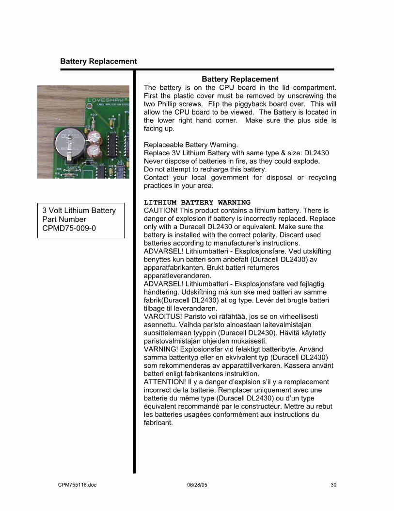
Battery Replacement
The battery is on the CPU board in the lid compartment. First the plastic cover must be removed by unscrewing the two Phillip screws. Flip the piggyback board over. This will allow the CPU board to be viewed. The Battery is located in the lower right hand corner. Make sure the plus side is facing up. Replaceable Battery Warning. Replace 3V Lithium Battery with same type & size: DL2430 Never dispose of batteries in fire, as they could explode. Do not attempt to recharge this battery. Contact your local government for disposal or recycling practices in your area. LITHIUM BATTERY WARNING CAUTION! This product contains a lithium battery. There is danger of explosion if battery is incorrectly replaced. Replace only with a Duracell DL2430 or equivalent. Make sure the battery is installed with the correct polarity. Discard used batteries according to manufacturer's instructions. ADVARSEL! Lithiumbatteri - Eksplosjonsfare. Ved utskifting benyttes kun batteri som anbefalt (Duracell DL2430) av apparatfabrikanten. Brukt batteri returneres apparatleverandøren. ADVARSEL! Lithiumbatteri - Eksplosjonsfare ved fejlagtig håndtering. Udskiftning må kun ske med batteri av samme fabrik(Duracell DL2430) at og type. Levér det brugte batteri tilbage til leverandøren. VAROITUS! Paristo voi räfähtää, jos se on virheellisesti asennettu. Vaihda paristo ainoastaan laitevalmistajan suosittelemaan tyyppin (Duracell DL2430). Hävitä käytetty paristovalmistajan ohjeiden mukaisesti. VARNING! Explosionsfar vid felaktigt batteribyte. Använd samma batterityp eller en ekvivalent typ (Duracell DL2430) som rekommenderas av apparattillverkaren. Kassera använt batteri enligt fabrikantens instruktion. ATTENTION! Il y a danger d’explsion s’il y a remplacement incorrect de la batterie. Remplacer uniquement avec une batterie du même type (Duracell DL2430) ou d’un type équivalent recommandè par le constructeur. Mettre au rebut les batteries usagées conformèment aux instructions du fabricant.
3 Volt Lithium Battery Part Number CPMD75-009-0
CPM755116.doc 06/28/05 31
Backflushing a Nozzle Plate
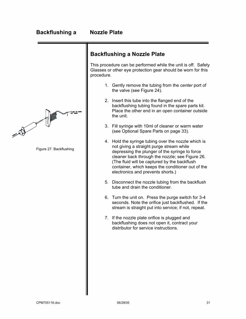
Figure 27. Backflushing
Backflushing a Nozzle Plate This procedure can be performed while the unit is off. Safety Glasses or other eye protection gear should be worn for this procedure.
1. Gently remove the tubing from the center port of the valve (see Figure 24).
2. Insert this tube into the flanged end of the
backflushing tubing found in the spare parts kit. Place the other end in an open container outside the unit.
3. Fill syringe with 10ml of cleaner or warm water
(see Optional Spare Parts on page 33).
4. Hold the syringe tubing over the nozzle which is not giving a straight purge stream while depressing the plunger of the syringe to force cleaner back through the nozzle; see Figure 26. (The fluid will be captured by the backflush container, which keeps the conditioner out of the electronics and prevents shorts.)
5. Disconnect the nozzle tubing from the backflush
tube and drain the conditioner.
6. Turn the unit on. Press the purge switch for 3-4 seconds. Note the orifice just backflushed. If the stream is straight put into service; if not, repeat.
7. If the nozzle plate orifice is plugged and
backflushing does not open it, contract your distributor for service instructions.
CPM755116.doc 06/28/05 32
Spare Parts Kit
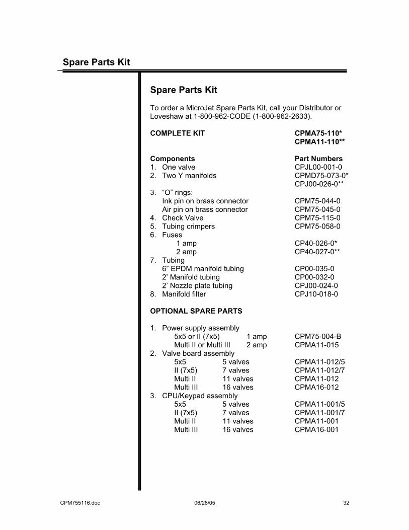
Spare Parts Kit To order a MicroJet Spare Parts Kit, call your Distributor or Loveshaw at 1-800-962-CODE (1-800-962-2633). COMPLETE KIT CPMA75-110* CPMA11-110** Components Part Numbers 1. One valve CPJL00-001-0 2. Two Y manifolds CPMD75-073-0* CPJ00-026-0** 3. “O” rings:
Ink pin on brass connector CPM75-044-0 Air pin on brass connector CPM75-045-0
4. Check Valve CPM75-115-0 5. Tubing crimpers CPM75-058-0 6. Fuses 1 amp CP40-026-0* 2 amp CP40-027-0** 7. Tubing
6” EPDM manifold tubing CP00-035-0 2’ Manifold tubing CP00-032-0 2’ Nozzle plate tubing CPJ00-024-0
8. Manifold filter CPJ10-018-0 OPTIONAL SPARE PARTS 1. Power supply assembly 5x5 or II (7x5) 1 amp CPM75-004-B Multi II or Multi III 2 amp CPMA11-015 2. Valve board assembly 5x5 5 valves CPMA11-012/5 II (7x5) 7 valves CPMA11-012/7 Multi II 11 valves CPMA11-012 Multi III 16 valves CPMA16-012 3. CPU/Keypad assembly 5x5 5 valves CPMA11-001/5 II (7x5) 7 valves CPMA11-001/7 Multi II 11 valves CPMA11-001 Multi III 16 valves CPMA16-001
CPM755116.doc 06/28/05 33
Spare Parts Kit
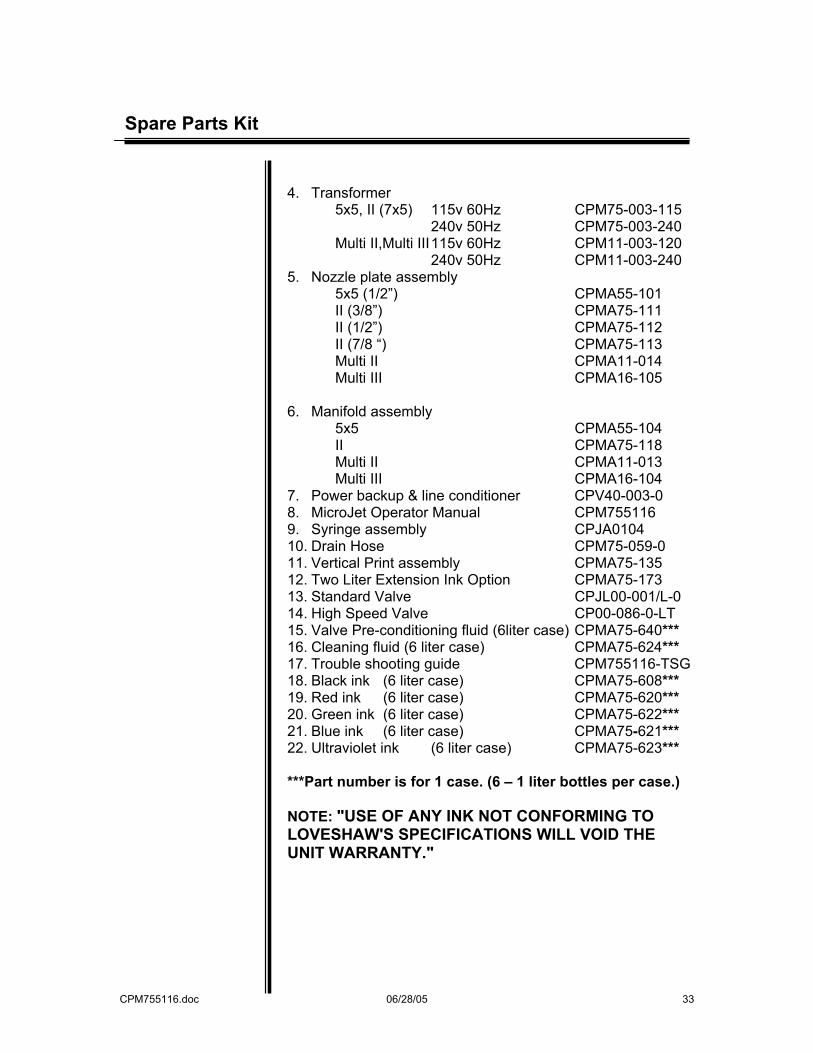
4. Transformer 5x5, II (7x5) 115v 60Hz CPM75-003-115 240v 50Hz CPM75-003-240 Multi II,Multi III 115v 60Hz CPM11-003-120 240v 50Hz CPM11-003-240 5. Nozzle plate assembly 5x5 (1/2”) CPMA55-101 II (3/8”) CPMA75-111 II (1/2”) CPMA75-112 II (7/8 “) CPMA75-113 Multi II CPMA11-014 Multi III CPMA16-105 6. Manifold assembly 5x5 CPMA55-104 II CPMA75-118 Multi II CPMA11-013 Multi III CPMA16-104 7. Power backup & line conditioner CPV40-003-0 8. MicroJet Operator Manual CPM755116 9. Syringe assembly CPJA0104 10. Drain Hose CPM75-059-0 11. Vertical Print assembly CPMA75-135 12. Two Liter Extension Ink Option CPMA75-173 13. Standard Valve CPJL00-001/L-0 14. High Speed Valve CP00-086-0-LT 15. Valve Pre-conditioning fluid (6liter case) CPMA75-640*** 16. Cleaning fluid (6 liter case) CPMA75-624*** 17. Trouble shooting guide CPM755116-TSG 18. Black ink (6 liter case) CPMA75-608*** 19. Red ink (6 liter case) CPMA75-620*** 20. Green ink (6 liter case) CPMA75-622*** 21. Blue ink (6 liter case) CPMA75-621*** 22. Ultraviolet ink (6 liter case) CPMA75-623*** ***Part number is for 1 case. (6 – 1 liter bottles per case.) NOTE: "USE OF ANY INK NOT CONFORMING TO LOVESHAW'S SPECIFICATIONS WILL VOID THE UNIT WARRANTY."
CPM755116.doc 06/28/05 34
Specifications
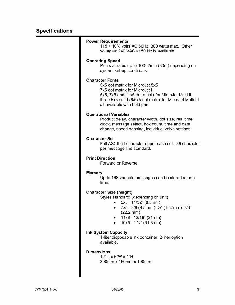
Power Requirements
115 + 10% volts AC 60Hz, 300 watts max. Other voltages: 240 VAC at 50 Hz is available.
Operating Speed
Prints at rates up to 100-ft/min (30m) depending on system set-up conditions.
Character Fonts
5x5 dot matrix for MicroJet 5x5 7x5 dot matrix for MicroJet II 5x5, 7x5 and 11x6 dot matrix for MicroJet Multi II three 5x5 or 11x6/5x5 dot matrix for MicroJet Multi III all available with bold print.
Operational Variables
Product delay, character width, dot size, real time clock, message select, box count, time and date change, speed sensing, individual valve settings.
Character Set
Full ASCII 64 character upper case set. 39 character per message line standard.
Print Direction
Forward or Reverse. Memory
Up to 168 variable messages can be stored at one time.
Character Size (height)
Styles standard: (depending on unit) • 5x5 11/32” (8.5mm) • 7x5 3/8 (9.5 mm); ½” (12.7mm); 7/8”
(22.2 mm) • 11x6 13/16” (21mm) • 16x6 1 ¼” (31.8mm)
Ink System Capacity
1-liter disposable ink container, 2-liter option available.
Dimensions
12” L x 6”W x 4”H 300mm x 150mm x 100mm
CPM755116.doc 06/28/05 35
Hints for Optimum Performance
Hints for Optimum Performance
• To adjust any MicroJet feature, including the print message, the “unlock” code must be entered (5863434). Once entered, the locked message will be cleared from the display.
• Familiarize yourself with the alpha and number
character keys and the symbols (available with the UPPER KEY key) as well as the capabilities of the control and command keys.
• It is not possible to estimate exactly how long a
bottle of ink will last because of the many variables – length of messages, double dotting and size of characters – but please note that the MicroJet has a low ink signal. When the light comes on, it is time to replenish the ink supply. Refer to page 28.
• It is recommended that the Box Guide should come
in contact with cartons for best print quality.
• Routine daily maintenance is recommended for optimum performance. See page 24.
• If there is too much ink in your codes, adjust the
SIZE or valve adjustments.
• If the code is unclear, purge until all nozzles give straight streams of ink. Backflush if necessary. See page 31 for instructions.
• If the code has uneven dot sizes after a valve
change, balance the new valve with the older ones. It’s a simple operation. See page 18.
• Regularly wipe the photocell covers with a
dampened cloth.
• To clear the MicroJet of all stored messages and print settings, turn the unit off, press and hold the number 6. Turn the unit on, wait about a second, release the 6, and then type 6 6 S L A M normally. If any error is made in typing the characters, the memory clear does not occur.
CPM755116.doc 06/28/05 36
Hints for Optimum Performance
• If the Internal compartment should flood with ink,
disconnect the power cord immediately and remove the in container. Rinse the ink from the ink compartment and dry thoroughly before returning unit to operation.
• Retain the shipping cap from the ink container. It
can be used to reseal the container should the unit need servicing and the ink container removed.
• If the unit must be returned to Loveshaw for
servicing, do not return it with the ink container still in the unit. This will cause flooding and further complicate the repair. REMOVE THE INK BOTTLE BEFORE SHIPPING.
NOTE: "USE OF ANY INK NOT CONFORMING TO LOVESHAW'S SPECIFICATIONS WILL VOID THE UNIT WARRANTY."
CPM755116.doc 06/28/05 37
Warranty
Little David® Warranty For:
MicroJet 5x5, MicroJet II, MicroJet Multi II, and MicroJet Multi III Ink-Jet printers.
2 YEAR WARRANTY ON VALVES 90 DAYS WARRANTY ON ALL OTHER PARTS *LIMITED WARRANTY – LOVESHAW, an ITW COMPANY (HEREIN AFTER “LOVESHAW”)
WARRANTS ONLY THAT THE GOODS SOLD BY IT SHALL BE FREE FROM DEFECTS IN MATERIAL AND WORKMANSHIP, UNDER PROPER AND NORMAL USE AND MAINTENANCE, AS FOLLOWS: VALVES - 2 YEARS from date of delivery. ALL OTHER PARTS - 90 DAYS from date of delivery. THE WARRANTY PERIOD SHALL COMMENCE AS OF THE DATE OF DELIVERY TO THE PURCHASER. THE OBLIGATION OF LOVESHAW UNDER THIS WARRANTY IS STRICTLY LIMITED TO THE COST OF REPAIRING OR REPLACING, AS LOVESHAW MAY ELECT, ANY PART OR PARTS THAT PROVE IN LOVESHAW’S JUDGEMENT TO HAVE BEEN DEFECTIVE IN MATERIAL OR WORKMANSHIP AT THE TIME THE GOODS WERE SHIPPED FROM LOVESHAW’S PLANT. ANY WARRANTY CLAIM NOT MADE IN WRITING TO LOVESHAW AT ITS HOME OFFICE WITHIN THE APPLICABLE WARRANTY PERIOD AND WITHIN 10 DAYS OF FAILURE WILL NOT BE VALID. THIS IS THE SOLE AND EXCLUSIVE REMEDY AVAILABLE UNDER THIS WARRANTY. UNDER NO CIRCUMSTANCES WILL LOVESHAW BE LIABLE FOR INCIDENTAL, SPECIAL OR CONSEQUENTIAL DAMAGES. IF REQUESTED BY LOVESHAW, PURCHASER SHALL RETURN ANY DEFECTIVE PART OR PARTS TO LOVESHAW’S PLANT, FREIGHT PREPAID. ALL WARRANTY PART REPLACEMENTS AND REPAIRS MUST BE MADE BY LOVESHAW OR A LOVESHAW DEALER AUTHORIZED TO HANDLE THE GOODS COVERED BY THIS WARRANTY. ANY OUTSIDE WORK OR ALTERATIONS DONE WITHOUT LOVESHAW’S PRIOR WRITTEN APPROVAL WILL RENDER THIS WARRANTY VOID. LOVESHAW, an ITW COMPANY WILL NOT ASSUME ANY EXPENSE OR LIABILITY FOR ANY REPAIRS MADE TO ITS GOODS OUTSIDE ITS WORKS WITHOUT ITS PRIOR WRITTEN CONSENT. THIS WARRANTY SHALL NOT APPLY TO ANY ITEM THAT HAS NOT BEEN USED, OPERATED, AND MAINTAINED IN ACCORDANCE WITH LOVESHAW’S RECOMMENDED PROCEDURES. LOVESHAW SHALL HAVE NO LIABILITY WHATSOEVER WHERE THE GOODS HAVE BEEN ALTERED, MISUSED, ABUSED OR INVOLVED IN AN ACCIDENT. NO PERSON IS AUTHORIZED TO MAKE ANY WARRANTY OR TO CREATE ANY LIABILITY BINDING UPON LOVESHAW, WHICH IS NOT STATED IN THIS WARRANTY. THIS WARRANTY IS EXPRESSLY IN LIEU OF ALL OTHER WARRANTIES OF ANY KIND, EXPRESSSED OR IMPLIED, WHICH ARE HEREBY EXCLUDED. IN PARTICULAR, THE IMPLIED WARRANTY OF MERCHANTABILITY, AS WELL AS THE IMPLIED WARRANTY OF FITNESS FOR A PARTICULAR PURPOSE ARE HEREBY EXCLUDED. Purchaser shall, before purchasing, determine the fitness and suitability of the said product LOVESHAW Ink Jet Printer for its intended purpose and neither manufacturer nor seller shall be liable for any loss or damage, direct or consequential, arising out of the use of or the inability to use the above described equipment. "USE OF ANY INK NOT CONFORMING TO LOVESHAW'S SPECIFICATIONS WILL VOID THE UNIT WARRANTY."
LOVESHAW an ITW Company 2206 Easton Turnpike, PO. Box 83 SOUTH CANAAN, PA 18459 570.937.4921 - 800.572.3434 - FAX 570.937.3229
CPM755116.doc 06/28/05 38
Insertion Sheets IMPORTANT Carefully remove the tubing loop before connecting the Ink Bottle. Pre-Conditioner Solution This product is filled with Pre-conditioner solution that contains ETHYLENE GLYCOL. Danger! Harmful - Avoid contact with eyes, skin, or clothing. Reference: MSDS for Pre-conditioner solution. IMPORTANTE Retire cuidadosamente el bucle de tubo antes de conectar el frasco de tinta SOLUCIÓN DE PREACONDICIONADOR Este producto ha sido llenado con una solución preacondicionadora que contiene GLICOL ETILENO. ¡PELIGRO! Es perjudicial- Evite el contacto con los ojos, la piel o la ropa. Referencia: Hoja de datos de seguridad del material (MSDS) para la solución preacondicionadora.
CPM755116.doc 06/28/05 39
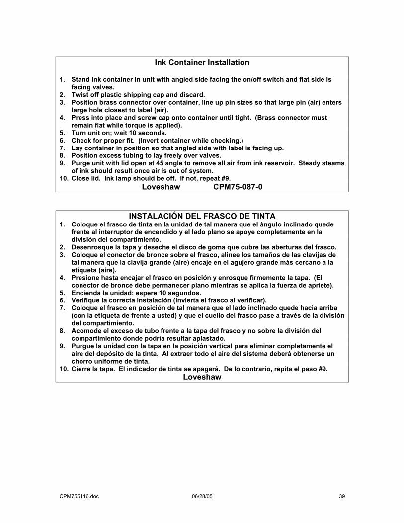
Ink Container Installation
1. Stand ink container in unit with angled side facing the on/off switch and flat side is
facing valves. 2. Twist off plastic shipping cap and discard. 3. Position brass connector over container, line up pin sizes so that large pin (air) enters
large hole closest to label (air). 4. Press into place and screw cap onto container until tight. (Brass connector must
remain flat while torque is applied). 5. Turn unit on; wait 10 seconds. 6. Check for proper fit. (Invert container while checking.) 7. Lay container in position so that angled side with label is facing up. 8. Position excess tubing to lay freely over valves. 9. Purge unit with lid open at 45 angle to remove all air from ink reservoir. Steady steams
of ink should result once air is out of system. 10. Close lid. Ink lamp should be off. If not, repeat #9.
Loveshaw CPM75-087-0
INSTALACIÓN DEL FRASCO DE TINTA 1. Coloque el frasco de tinta en la unidad de tal manera que el ángulo inclinado quede
frente al interruptor de encendido y el lado plano se apoye completamente en la división del compartimiento.
2. Desenrosque la tapa y deseche el disco de goma que cubre las aberturas del frasco. 3. Coloque el conector de bronce sobre el frasco, alinee los tamaños de las clavijas de
tal manera que la clavija grande (aire) encaje en el agujero grande más cercano a la etiqueta (aire).
4. Presione hasta encajar el frasco en posición y enrosque firmemente la tapa. (El conector de bronce debe permanecer plano mientras se aplica la fuerza de apriete).
5. Encienda la unidad; espere 10 segundos. 6. Verifique la correcta instalación (invierta el frasco al verificar). 7. Coloque el frasco en posición de tal manera que el lado inclinado quede hacia arriba
(con la etiqueta de frente a usted) y que el cuello del frasco pase a través de la división del compartimiento.
8. Acomode el exceso de tubo frente a la tapa del frasco y no sobre la división del compartimiento donde podría resultar aplastado.
9. Purgue la unidad con la tapa en la posición vertical para eliminar completamente el aire del depósito de la tinta. Al extraer todo el aire del sistema deberá obtenerse un chorro uniforme de tinta.
10. Cierre la tapa. El indicador de tinta se apagará. De lo contrario, repita el paso #9. Loveshaw
CPM755116.doc 06/28/05 40
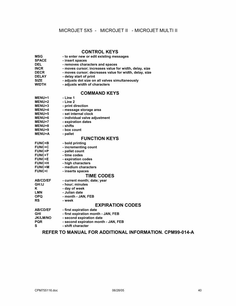
MICROJET 5X5 - MICROJET II - MICROJET MULTI II
CONTROL KEYS MSG - to enter new or edit existing messages SPACE - insert spaces DEL - removes characters and spaces INCR - moves cursor; increases value for width, delay, size DECR - moves cursor; decreases value for width, delay, size DELAY - delay start of print SIZE - adjusts dot size on all valves simultaneously WIDTH - adjusts width of characters
COMMAND KEYS MENU+1 - Line 1 MENU+2 - Line 2 MENU+3 - print direction MENU+4 - message storage area MENU+5 - set internal clock MENU+6 - individual valve adjustment MENU+7 - expiration dates MENU+8 - shifts MENU+9 - box count MENU+A - pallet
FUNCTION KEYS FUNC+B - bold printing FUNC+C - incrementing count FUNC+P - pallet count FUNC+T - time codes FUNC+E - expiration codes FUNC+H - high characters FUNC+M - medium characters FUNC+I - inserts spaces
TIME CODES AB/CD/EF - current month; date; year GH:IJ - hour; minutes K - day of week LMN - Julian date OPQ - month - JAN, FEB RS - week
EXPIRATION CODES AB/CD/EF - first expiration date GHI - first expiration month - JAN, FEB JK/LM/NO - second expiration date PQR - second expiraton month - JAN, FEB S - shift character
REFER TO MANUAL FOR ADDITIONAL INFORMATION. CPM99-014-A
CPM755116.doc 06/28/05 41
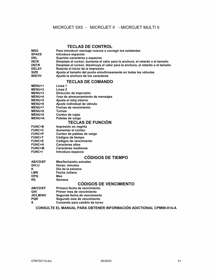
MICROJET 5X5 - MICROJET II - MICROJET MULTI II
TECLAS DE CONTROL MSG Para introducir mensaje nuevos o corregir los existentes SPACE Introduce espacios DEL Suprime caracteres y espacios INCR Desplaze el cursor; aumenta el valor para la anchura, el retardo o el tamaño DECR Desplaze el cursor; disminuye el valor para la anchura, el retardo o el tamaño DELAY Retarda el inicio de la impresión SIZE Ajusta el tamaño del punto simultáneamente en todas las válvulas WIDTH Ajusta la anchura de los caracteres
TECLAS DE COMANDO MENU+1 Línea 1 MENU+2 Línea 2 MENU+3 Dirección de impresión MENU+4 Área de almacenamiento de mensajes MENU+5 Ajusta el reloj interno MENU+6 Ajuste individual de válvula MENU+7 Fechas de vencimiento MENU+8 Turnos MENU+9 Conteo de cajas MENU+A Paletas de carga
TECLAS DE FUNCIÓN FUNC+B Impresión en negrita FUNC+C Aumentar el conteo FUNC+P Conteo de paletas de carga FUNC+T Códigos de tiempo FUNC+E Códigos de vencimiento FUNC+H Caracteres altos FUNC+M Caracteres medianos FUNC+I Introduce espacos
CÓDIGOS DE TIEMPO AB/CD/EF Mes/fecha/año actuales GH:IJ Horas: minutos K Día da la semana LMN Fecha Juliana OPQ Mes RS Semana
CÓDIGOS DE VENCIMIENTO AB/CD/EF Primera fecha de vencimiento GHI Primer mes de vencimiento JK/LM/NO Segunda fecha de vencimiento PQR Segundo mes de vencimiento S Comando para cambio de turno
CONSULTE EL MANUAL PARA OBTENER INFORMACIÓN ADICTIONAL CPM99-014-A
CPM755116.doc 06/28/05 42
MICROJET MULTI III
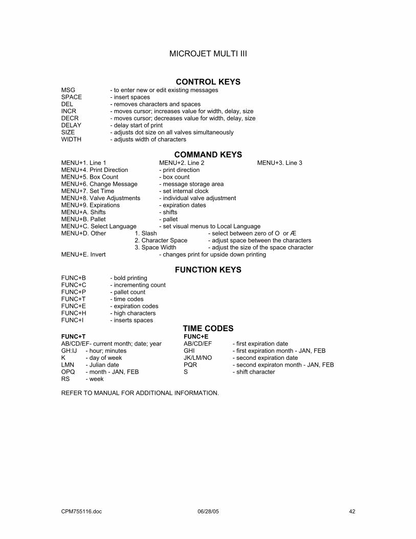
CONTROL KEYS MSG - to enter new or edit existing messages SPACE - insert spaces DEL - removes characters and spaces INCR - moves cursor; increases value for width, delay, size DECR - moves cursor; decreases value for width, delay, size DELAY - delay start of print SIZE - adjusts dot size on all valves simultaneously WIDTH - adjusts width of characters
COMMAND KEYS MENU+1. Line 1 MENU+2. Line 2 MENU+3. Line 3 MENU+4. Print Direction - print direction MENU+5. Box Count - box count MENU+6. Change Message - message storage area MENU+7. Set Time - set internal clock MENU+8. Valve Adjustments - individual valve adjustment MENU+9. Expirations - expiration dates MENU+A. Shifts - shifts MENU+B. Pallet - pallet MENU+C. Select Language - set visual menus to Local Language MENU+D. Other 1. Slash - select between zero of O or Æ 2. Character Space - adjust space between the characters 3. Space Width - adjust the size of the space character MENU+E. Invert - changes print for upside down printing
FUNCTION KEYS FUNC+B - bold printing FUNC+C - incrementing count FUNC+P - pallet count FUNC+T - time codes FUNC+E - expiration codes FUNC+H - high characters FUNC+I - inserts spaces
TIME CODES FUNC+T FUNC+E AB/CD/EF- current month; date; year AB/CD/EF - first expiration date GH:IJ - hour; minutes GHI - first expiration month - JAN, FEB K - day of week JK/LM/NO - second expiration date LMN - Julian date PQR - second expiraton month - JAN, FEB OPQ - month - JAN, FEB S - shift character RS - week REFER TO MANUAL FOR ADDITIONAL INFORMATION.
CPM755116.doc 06/28/05 43
MICROJET 5X5 - MICROJET II - MICROJET MULTI II
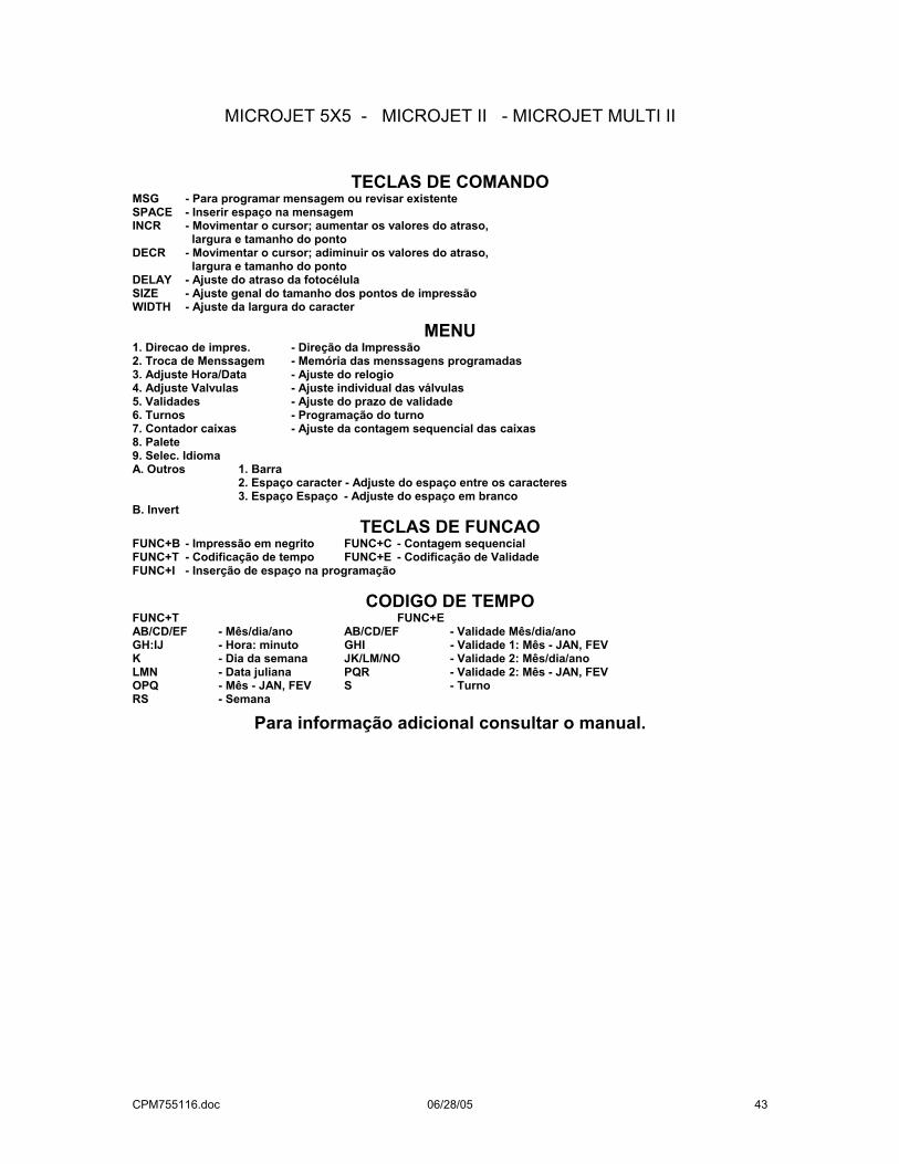
TECLAS DE COMANDO MSG - Para programar mensagem ou revisar existente SPACE - Inserir espaço na mensagem INCR - Movimentar o cursor; aumentar os valores do atraso, largura e tamanho do ponto DECR - Movimentar o cursor; adiminuir os valores do atraso, largura e tamanho do ponto DELAY - Ajuste do atraso da fotocélula SIZE - Ajuste genal do tamanho dos pontos de impressão WIDTH - Ajuste da largura do caracter
MENU 1. Direcao de impres. - Direção da Impressão 2. Troca de Menssagem - Memória das menssagens programadas 3. Adjuste Hora/Data - Ajuste do relogio 4. Adjuste Valvulas - Ajuste individual das válvulas 5. Validades - Ajuste do prazo de validade 6. Turnos - Programação do turno 7. Contador caixas - Ajuste da contagem sequencial das caixas 8. Palete 9. Selec. Idioma A. Outros 1. Barra 2. Espaço caracter - Adjuste do espaço entre os caracteres 3. Espaço Espaço - Adjuste do espaço em branco B. Invert
TECLAS DE FUNCAO FUNC+B - Impressão em negrito FUNC+C - Contagem sequencial FUNC+T - Codificação de tempo FUNC+E - Codificação de Validade FUNC+I - Inserção de espaço na programação
CODIGO DE TEMPO FUNC+T FUNC+E AB/CD/EF - Mês/dia/ano AB/CD/EF - Validade Mês/dia/ano GH:IJ - Hora: minuto GHI - Validade 1: Mês - JAN, FEV K - Dia da semana JK/LM/NO - Validade 2: Mês/dia/ano LMN - Data juliana PQR - Validade 2: Mês - JAN, FEV OPQ - Mês - JAN, FEV S - Turno RS - Semana
Para informação adicional consultar o manual.

![DVT - Multi FOV [12x9 - 5x5], [8x8 - 5x5] oder [5x5], OPG 2-in-1, … · DVT - Multi FOV [12x9 - 5x5], [8x8 - 5x5] oder [5x5], OPG 2-in-1, CEPH One-Shot oder Scan-Ceph optional, 3-in-1](https://img.pdfslide.net/doc/110x75/61024a32d7dc9526313ea8da/dvt-multi-fov-12x9-5x5-8x8-5x5-oder-5x5-opg-2-in-1-dvt-multi-fov.jpg)