Embed Size (px)
Citation preview
Conference Paper, Published Version
Liu, Y.; Zou, Z. J.; Zou, L.Rans-Based Numerical Simulation of Captive Model Testsin Shallow Water for the DCT Container CarrierZur Verfügung gestellt in Kooperation mit/Provided in Cooperation with:Flanders Hydraulics Research, Ghent University, Maritime Technology
Verfügbar unter/Available at: https://hdl.handle.net/20.500.11970/99853
Vorgeschlagene Zitierweise/Suggested citation:Liu, Y.; Zou, Z. J.; Zou, L. (2016): Rans-Based Numerical Simulation of Captive Model Testsin Shallow Water for the DCT Container Carrier. In: Uliczka, Klemens; Böttner, Carl-Uwe;Kastens, Marko; Eloot, Katrien; Delefortrie, Guillaume; Vantorre, Marc; Candries, Maxim;Lataire, Evert (Hg.): 4th MASHCON - International Conference on Ship Manoeuvring inShallow and Confined Water with Special Focus on Ship Bottom Interaction. Karlsruhe:Bundesanstalt für Wasserbau. S. 73-82. https://dx.doi.org/10.18451/978-3-939230-38-0_10.
Standardnutzungsbedingungen/Terms of Use:
Die Dokumente in HENRY stehen unter der Creative Commons Lizenz CC BY 4.0, sofern keine abweichendenNutzungsbedingungen getroffen wurden. Damit ist sowohl die kommerzielle Nutzung als auch das Teilen, dieWeiterbearbeitung und Speicherung erlaubt. Das Verwenden und das Bearbeiten stehen unter der Bedingung derNamensnennung. Im Einzelfall kann eine restriktivere Lizenz gelten; dann gelten abweichend von den obigenNutzungsbedingungen die in der dort genannten Lizenz gewährten Nutzungsrechte.
Documents in HENRY are made available under the Creative Commons License CC BY 4.0, if no other license isapplicable. Under CC BY 4.0 commercial use and sharing, remixing, transforming, and building upon the materialof the work is permitted. In some cases a different, more restrictive license may apply; if applicable the terms ofthe restrictive license will be binding.
RANS-BASED NUMERICAL SIMULATION OF CAPTIVE MODEL TESTS IN SHALLOW
WATER FOR THE DTC CONTAINER CARRIER
Y Liu, School of Naval Architecture, Ocean and Civil Engineering, Shanghai Jiao Tong University, Shanghai, China
Z J Zou, School of Naval Architecture, Ocean and Civil Engineering, State Key Laboratory of Ocean Engineering,
Shanghai Jiao Tong University, Shanghai, China; Collaborative Innovation Center for Advanced Ship and Deep-Sea
Exploration, Shanghai, China
L Zou, School of Naval Architecture, Ocean and Civil Engineering, Shanghai Jiao Tong University, Shanghai, China
SUMMARY
In very shallow water, the effect of depth restriction is very significant and dominates ship manoeuvrability. In this pa-
per, numerical simulations of the viscous flow around a bare hull of the DTC container carrier manoeuvring in shallow
water are conducted at model scale using the CFD software STAR CCM+. RANS-based simulations of static drift and
pure sway tests at 20% UKC and two forward speeds are carried out considering the dynamic sinkage and trim as well as
the tank wall effect. The hydrodynamic forces acting on the hull, as well as dynamic sinkage and trim are predicted and
discussed. Compared with the model test data, time histories of the forces and moments obtained from numerical simula-
tions show satisfactory agreement, while some discrepancies are found in the dynamic sinkage and trim simulations.
NOMENCLATURE 𝑎𝑎 Surface area (m
2) 𝑏𝑏 Breadth of ship (m) 𝐵𝐵 Width of tank (m)
F External body force (N) 𝐻𝐻 Depth of water of tank (m)
𝐼𝐼 Identity matrix (-)
p Pressure (N/m2)
RT Total resistance (N) 𝑆𝑆𝑚𝑚 Blockage factor (-)
Τ Ship’s even keel static draft (m)
tr Transpose of the matrix (-) 𝑣𝑣 Velocity (m/s) 𝑣𝑣𝑔𝑔 Mesh grid velocity (m/s)
V A cell of volume (m3)
Y+ Dimensionless wall distance (-)
𝛼𝛼 Volume fraction (-) 𝛤𝛤 Viscous stress (N/m2)
𝜇𝜇𝑅𝑅𝑒𝑒𝑒𝑒 Sum of the laminar 𝜇𝜇 and turbulence
viscosities 𝜇𝜇𝑐𝑐 (N s/ m2) 𝜌𝜌 Density of water (kg/m3)
DFBI Dynamic Fluid Body Interaction
RANS Reynolds-averaged Navier Stokes
UKC Under-Keel Clearance
1 INTRODUCTION
A ship manoeuvring in restricted waters usually experi-
ences much larger hydrodynamic forces than in unre-
stricted waters due to the hydrodynamic interaction be-
tween the ship and the bottom/bank of the waterway.
This hydrodynamic interaction has detrimental influence
on ship manoeuvrability and may result in marine acci-
dents such as collision or grounding. The ship experienc-
es dynamic sinkage and trim (squat), notably in very
shallow waters, due to the hydrodynamic forces acting on
the hull. In addition to the squat, shallow water flows are
influenced by various factors such as free surface eleva-
tion, tank wall blockage, ship speed, bank geometry,
unsteady flow features, water depth, etc. Therefore, to
ensure a safe navigation it is of great importance to accu-
rately predict the hydrodynamic force acting on the ship
by taking the shallow water effect into account.
Traditionally, model tests, full scale trials and theoretical
and semi-theoretical methods are used to predict the
squat and the hydrodynamic force acting on a manoeu-
vring ship [1, 2]. Among several methods for manoeu-
vring prediction, static or dynamic planar motion mecha-
nism (PMM) test is one of the most commonly used
approaches. Captive model tests were executed and the
shallow water effect on ship manoeuvring was discussed
[3, 4]. Some free-running tests in shallow water were
also presented [5, 6]. Furthermore, programs based on
slender-body theory were used to model the hydrody-
namic flow around ships in shallow water [7, 8].
Nowadays, with the rapid development of computer
technique and Computational Fluid Dynamics (CFD)
method, CFD-based numerical prediction of the hydro-
dynamic forces has become possible. Ship manoeuvring
predictions by solving unsteady Reynolds-averaged Na-
vier Stokes (RANS) equations have been presented in
SIMMAN 2008 Workshop [9]. In addition to the deep
water manoeuvres, SIMMAN 2014 Workshop also fo-
cused on ship manoeuvring in shallow water [10]. In the
past, there were many studies regarding the simulation of
static manoeuvres [11, 12] while the unsteady manoeu-
vres were not covered, the situation has been changed
recently [5, 13-14]. Free-running tests such as zigzag and
turning manoeuvres were numerically studied in refer-
ence [5]. Captive model tests were numerically simulated
for different drift angles, water depth to draft ratios and
ship speeds [15-18]. As presented by these investiga-
tions, shallow water effect can be simulated by CFD but
still without enough accuracy, especially in the very
shallow water condition with below 20% UKC.
4th MASHCON, Hamburg - Uliczka et al. (eds) - © 2016 Bundesanstalt für Wasserbau ISBN 978-3-939230-38-0 (Online)
DOI: 10.18451/978-3-939230-38-0_10
73
To further investigate the interaction between a ship and
the bottom of a shallow waterway, this paper uses the
benchmark cases of a DTC container carrier, which are
provided by Flanders Hydraulics Research (FHR) and
Ghent University [19] for the 4th Conference on
Manoeuvring in Shallow and Confined Water (MASH-
CON2016). The benchmark model tests contain harmon-
ic yaw and harmonic sway tests with the DTC at 20%
UKC. In this paper, numerical simulations of the viscous
flow around the DTC bare hull manoeuvring in shallow
water are conducted at model scale using the CFD soft-
ware STAR CCM+. RANS-based simulations of the
static drift and pure sway tests at 20% UKC are carried
out considering the dynamic sinkage and trim as well as
the side walls of the towing tank as in the model tests.
The effect of free surface elevation on the hydrodynamic
forces is included by using the Volume of Fluid (VOF)
method. The numerical results are compared with the
benchmark data and the hydrodynamic characteristics of
ship-to-bottom interaction are analyzed.
2 MATHEMATICAL FORMULATION
The governing equations are RANS equations which are
closed by modeling the Reynolds stress tensor using SST
k-ω turbulence model. Mean flow quantities near the
wall are simulated according to an all Y+ wall treatment
where blended wall function is adopted. This approach is
flexible because of its ability to handle a range of local
mesh refinement levels near the wall. Cells with low Y+
values are assumed to be properly resolved such that no
wall treatment is necessary, while cells of Y+>30 are
treated as in the logarithmic region. Simulation of the
viscous flow around the DTC hull is obtained through a
finite volume discretization of the numerical domain. A
VOF method is employed to capture the position of the
phase interface between water and air. Equations are
solved as an uncoupled system using a segregated flow
solver which employs a SIMPLE algorithm for pressure-
velocity coupling.
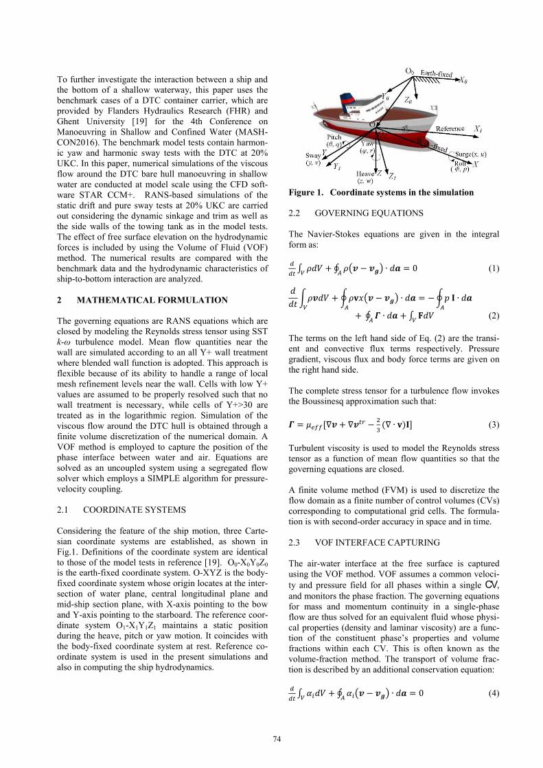
2.1 COORDINATE SYSTEMS
Considering the feature of the ship motion, three Carte-
sian coordinate systems are established, as shown in
Fig.1. Definitions of the coordinate system are identical
to those of the model tests in reference [19]. O0-X0Y0Z0
is the earth-fixed coordinate system. O-XYZ is the body-
fixed coordinate system whose origin locates at the inter-
section of water plane, central longitudinal plane and
mid-ship section plane, with X-axis pointing to the bow
and Y-axis pointing to the starboard. The reference coor-
dinate system O1-X1Y1Z1 maintains a static position
during the heave, pitch or yaw motion. It coincides with
the body-fixed coordinate system at rest. Reference co-
ordinate system is used in the present simulations and
also in computing the ship hydrodynamics.
Figure 1. Coordinate systems in the simulation
2.2 GOVERNING EQUATIONS
The Navier-Stokes equations are given in the integral
form as:
𝑑𝑑𝑑𝑑𝑐𝑐 ∫ 𝜌𝜌𝑑𝑑𝜌𝜌𝑉𝑉 + ∮ 𝜌𝜌�𝒗𝒗 − 𝒗𝒗𝒈𝒈�𝑂𝑂 ∙ 𝑑𝑑𝒂𝒂 = 0 (1)
𝑑𝑑𝑑𝑑𝑐𝑐 �𝜌𝜌𝒗𝒗𝑑𝑑𝜌𝜌𝑉𝑉 + �𝜌𝜌𝐯𝐯𝑥𝑥�𝒗𝒗 − 𝒗𝒗𝒈𝒈�𝑂𝑂 ∙ 𝑑𝑑𝒂𝒂 = −�𝑝𝑝 𝐈𝐈 ∙ 𝑑𝑑𝒂𝒂𝑂𝑂
+ ∮ 𝜞𝜞 ∙ 𝑑𝑑𝒂𝒂𝑂𝑂 + ∫ 𝐅𝐅𝑑𝑑𝜌𝜌𝑉𝑉 (2)
The terms on the left hand side of Eq. (2) are the transi-
ent and convective flux terms respectively. Pressure
gradient, viscous flux and body force terms are given on
the right hand side.
The complete stress tensor for a turbulence flow invokes
the Boussinesq approximation such that:
𝜞𝜞 = 𝜇𝜇𝑅𝑅𝑒𝑒𝑒𝑒[∇𝒗𝒗 + ∇𝒗𝒗𝑐𝑐𝑐𝑐 − 23 (∇ ∙ 𝐯𝐯)𝐈𝐈] (3)
Turbulent viscosity is used to model the Reynolds stress
tensor as a function of mean flow quantities so that the
governing equations are closed.
A finite volume method (FVM) is used to discretize the
flow domain as a finite number of control volumes (CVs)
corresponding to computational grid cells. The formula-
tion is with second-order accuracy in space and in time.
2.3 VOF INTERFACE CAPTURING
The air-water interface at the free surface is captured
using the VOF method. VOF assumes a common veloci-
ty and pressure field for all phases within a single CV,
and monitors the phase fraction. The governing equations
for mass and momentum continuity in a single-phase
flow are thus solved for an equivalent fluid whose physi-
cal properties (density and laminar viscosity) are a func-
tion of the constituent phase’s properties and volume
fractions within each CV. This is often known as the
volume-fraction method. The transport of volume frac-
tion is described by an additional conservation equation:
𝑑𝑑𝑑𝑑𝑐𝑐 ∫ 𝛼𝛼𝑖𝑖𝑑𝑑𝜌𝜌𝑉𝑉 + ∮ 𝛼𝛼𝑖𝑖�𝒗𝒗 − 𝒗𝒗𝒈𝒈�𝑂𝑂 ∙ 𝑑𝑑𝒂𝒂 = 0 (4)
74
modules is that the former involves the whole mesh mov-
ing, while the latter uses control points and their associ-
ated displacements to generate an interpolation field
throughout the region, which can then be used to displace
the actual vertices of a mesh. “Six Dof Body” boundary
and “Six Dof Body plus Displacement” are selected in
DFBI morphing motion to trace the vertices on this
boundary. User defined functions are written and added
to the Field Function to define the additional specified
displacement superposed in the 6-DOF body motion. All
the simulations are carried out on a shared-memory
workstation with 16 CPU cores (Intel XEON @
2.60GHz).
4 RESULTS AND DISCUSSIONS
4.1 SIMULATIONS OF STATIC CAPTIVE MODEL
TESTS IN DEEP AND SHALLOW WATER
4.1 (a) Validation of straight ahead test in deep water
In order to evaluate the accuracy of the numerical meth-
od, deep water case is simulated by two motion modules,
i.e. DFBI Translation and Rotation and DFBI morphing.
During all the simulations, sinkage and trim are free. The
total resistance RT of DTC hull under straight-ahead
conditions is obtained and compared with the experi-
mental data [20]. Table 1 shows the comparison between
the CFD results and experimental data (EFD) at
Re=8.054 × 10⁶ and Fr=0.192, where “E%D” denotes
the relative error.
Table 1. Resistance results in deep water ______________________________________________
Case* RT (N) E%D (%)* ______________________________________________
EFD 24.14 (-)
DFBI Translation and Rotation 25.146 4.1665
DFBI morphing 25.09 3.9373 _____________________________________________
* Ship model scale 1: 59.407
* E%D = (CFD-EFD)/ EFD×100%
From Table 1, it can be seen that both of these two nu-
merical methods over-predict the resistance, but their
relative errors are small and DFBI morphing method is
slightly better. Because the method of DFBI Translation
and Rotation cannot solve the near wall problem when
considering squat, DFBI morphing method is selected for
the following computations.
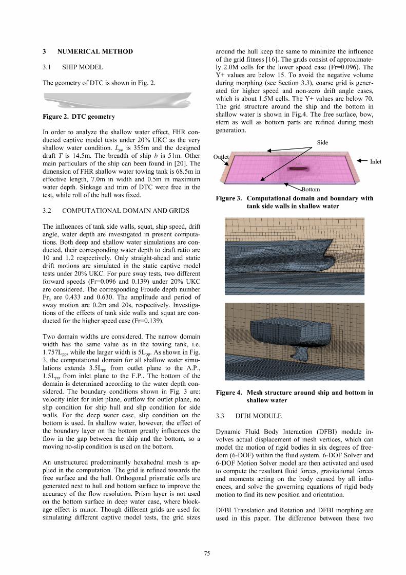
4.1 (b) Validation of static drift test in shallow water
In this section, straight-ahead (β = 0°) and static drift
(β = 2.5°) motions are numerically simulated under 20%
UKC. Modeling static drift motion in shallow water is
more difficult comparing to the deep water case due to
the blockage effects, and it is much more time-
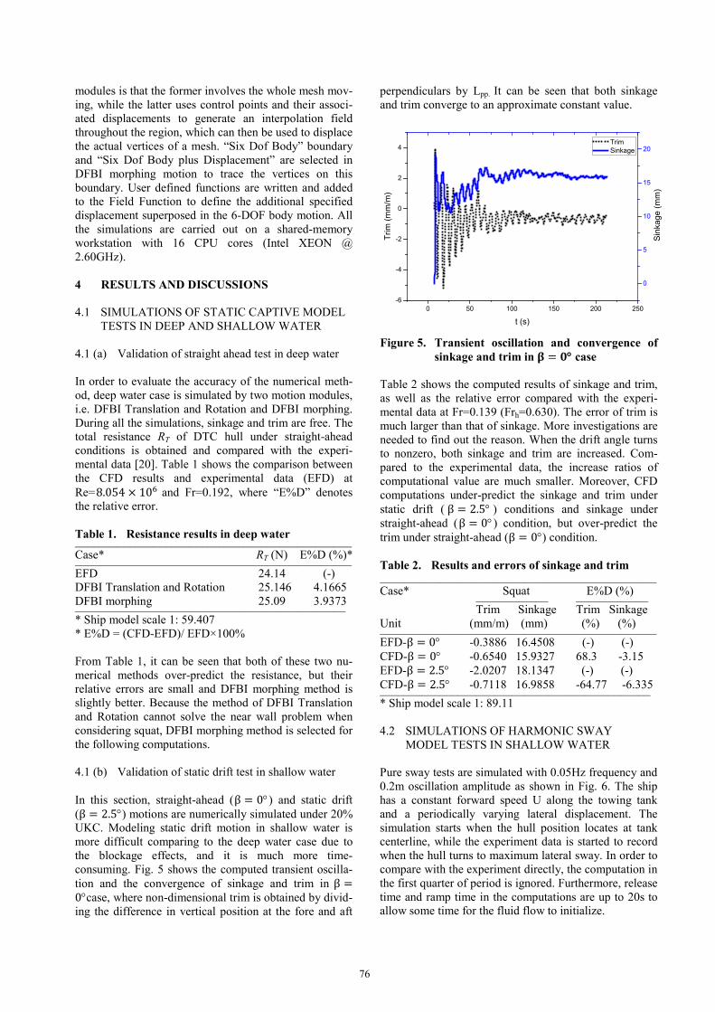
consuming. Fig. 5 shows the computed transient oscilla-
tion and the convergence of sinkage and trim in β =
0°case, where non-dimensional trim is obtained by divid-
ing the difference in vertical position at the fore and aft
perpendiculars by Lpp. It can be seen that both sinkage
and trim converge to an approximate constant value.
Figure 5. Transient oscillation and convergence of
sinkage and trim in 𝛃𝛃 = 𝟎𝟎° case
Table 2 shows the computed results of sinkage and trim,
as well as the relative error compared with the experi-
mental data at Fr=0.139 (Frh=0.630). The error of trim is
much larger than that of sinkage. More investigations are
needed to find out the reason. When the drift angle turns
to nonzero, both sinkage and trim are increased. Com-
pared to the experimental data, the increase ratios of
computational value are much smaller. Moreover, CFD
computations under-predict the sinkage and trim under
static drift ( β = 2.5° ) conditions and sinkage under
straight-ahead (β = 0°) condition, but over-predict the
trim under straight-ahead (β = 0°) condition.
Table 2. Results and errors of sinkage and trim ______________________________________________
Case* Squat E%D (%) ____________ ____________
Trim Sinkage Trim Sinkage
Unit (mm/m) (mm) (%) (%) ______________________________________________
EFD-β = 0° -0.3886 16.4508 (-) (-)
CFD-β = 0° -0.6540 15.9327 68.3 -3.15
EFD-β = 2.5° -2.0207 18.1347 (-) (-)
CFD-β = 2.5° -0.7118 16.9858 -64.77 -6.335 _____________________________________________
* Ship model scale 1: 89.11
4.2 SIMULATIONS OF HARMONIC SWAY
MODEL TESTS IN SHALLOW WATER
Pure sway tests are simulated with 0.05Hz frequency and
0.2m oscillation amplitude as shown in Fig. 6. The ship
has a constant forward speed U along the towing tank
and a periodically varying lateral displacement. The
simulation starts when the hull position locates at tank
centerline, while the experiment data is started to record
when the hull turns to maximum lateral sway. In order to
compare with the experiment directly, the computation in
the first quarter of period is ignored. Furthermore, release
time and ramp time in the computations are up to 20s to
allow some time for the fluid flow to initialize.
0 50 100 150 200 250
-6
-4
-2
0
2
4 Trim
Sinkage
t (s)
Trim
(m
m/m
)
0
5
10
15
20
Sin
kage (
mm
)
76
Figure 6. Pure sway (model scale 1: 89.11)
4.2 (a) Frh=0.63
In order to discuss how the squat and tank side walls
affect the hydrodynamic forces in shallow water, four
different cases are numerically simulated at Frh=0.63.The
case definition and parameters are summarized in Table
3. Two domain widths and blockage factors Sm are listed
there. Two kinds of ship states are considered. Dynamic
ship squat is numerically simulated as model tests while
fixed ship has zero sinkage and trim.
Table 3. Cases definition and parameters ______________________________________________
Case No. Domain *Sm State Sinkage trim ______________________________________________
1 wide 0.024 fixed 0 0
2 bank 0.069 fixed 0 0
3 wide 0.024 squat dynamic dynamic
4 bank 0.069 squat dynamic dynamic _____________________________________________ *Sm = (𝑏𝑏 × 𝑇𝑇)/(𝐵𝐵 × 𝐻𝐻)
Fig. 7-Fig. 9 show the hydrodynamic forces and mo-
ments of these four cases, as well as the comparison with
the experimental data. These figures show that the hy-
drodynamic forces and moments obtained for Case 4 are
the most accurate ones compared to the experimental
data. When both ship squat and tank side walls are ig-
nored (Case 1), the amplitudes of lateral force and yaw
moment decrease by more than 50% compared with the
results of Case 4. When comparing the results of Case 2
and Case 3 with those of Case 4, the amplitude of hydro-
dynamic forces and moment of Case3 is quantitatively
larger than those of Case 2. It means that the squat plays
a more important role in affecting hydrodynamic forces
than the blockage effect by the tank side walls. In Case 4,
CFD prediction gives the best results but still there are
discrepancies. It under-predicts lateral force while over-
predicts yaw moment at peak values.
Fig. 10 and Fig. 11 show the dynamic sinkage and trim
during pure sway in 2 periods. For Case 4, the same
trends of the sinkage and trim are predicted qualitatively
as in the tests, but with some error in value. Case 4 has a
relative better trend than Case 3 since the time when the
sinkage and trim value reaches extreme points in Case 4
basically coincides with experiment data. Nevertheless,
the sinkage is much under-predicted compared with EFD
data. The large errors in computations are probably
caused by the coarse grid or the increased complexity of
the flow. The experimental investigations do not show a
fully steady state of ship’s sinkage and trim neither.
Since the error and uncertainty of the model test data are
not available, it is difficult to draw any conclusion so far.
Figure 7. Time history of longitudinal force
(Frh=0.63)
Figure 8. Time history of lateral force (Frh=0.63)
0 10 20 30 40
-0.2
-0.1
0.0
0.1
0.2
late
ral p
ositio
n (
m)
t (s)
CFD
EFD
0 10 20 30 40
-20
-18
-16
-14
-12
-10
-8
-6
-4
-2
Longitudin
al fo
rce (
N)
t (s)
wide-squat
bank-squat
wide-fixed
bank-fixed
EFD
0 10 20 30 40
-80
-60
-40
-20
0
20
40
60
80
Late
ral fo
rce (
N)
t (s)
wide-squat
bank-squat
wide-fixed
bank-fixed
EFD
77
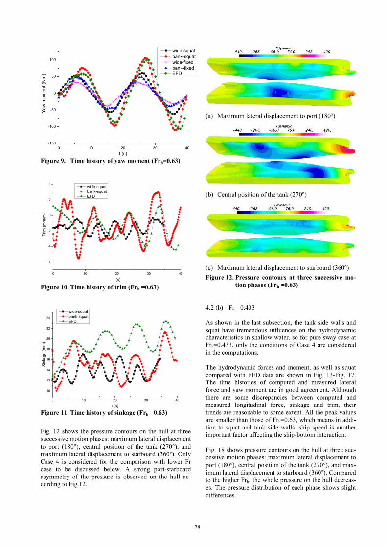
Figure 9. Time history of yaw moment (Frh=0.63)
Figure 10. Time history of trim (Frh =0.63)
Figure 11. Time history of sinkage (Frh =0.63)
Fig. 12 shows the pressure contours on the hull at three
successive motion phases: maximum lateral displacement
to port (180°), central position of the tank (270°), and
maximum lateral displacement to starboard (360°). Only
Case 4 is considered for the comparison with lower Fr
case to be discussed below. A strong port-starboard
asymmetry of the pressure is observed on the hull ac-
cording to Fig.12.
(a) Maximum lateral displacement to port (180°)
(b) Central position of the tank (270°)
(c) Maximum lateral displacement to starboard (360°)
Figure 12. Pressure contours at three successive mo-
tion phases (Frh =0.63)
4.2 (b) Frh=0.433
As shown in the last subsection, the tank side walls and
squat have tremendous influences on the hydrodynamic
characteristics in shallow water, so for pure sway case at
Frh=0.433, only the conditions of Case 4 are considered
in the computations.
The hydrodynamic forces and moment, as well as squat
compared with EFD data are shown in Fig. 13-Fig. 17.
The time histories of computed and measured lateral
force and yaw moment are in good agreement. Although
there are some discrepancies between computed and
measured longitudinal force, sinkage and trim, their
trends are reasonable to some extent. All the peak values
are smaller than those of Frh=0.63, which means in addi-
tion to squat and tank side walls, ship speed is another
important factor affecting the ship-bottom interaction.
Fig. 18 shows pressure contours on the hull at three suc-
cessive motion phases: maximum lateral displacement to
port (180°), central position of the tank (270°), and max-
imum lateral displacement to starboard (360°). Compared
to the higher Frh, the whole pressure on the hull decreas-
es. The pressure distribution of each phase shows slight
differences.
0 10 20 30 40
-150
-100
-50
0
50
100
Ya
w m
om
en
t (N
m)
t (s)
wide-squat
bank-squat
wide-fixed
bank-fixed
EFD
0 10 20 30 40
-6
-4
-2
0
2
4
Trim
(m
m/m
)
t (s)
wide-squat
bank-squat
EFD
0 10 20 30 40
10
12
14
16
18
20
22
24
Sin
kage (
mm
)
t (s)
wide-squat
bank-squat
EFD
78
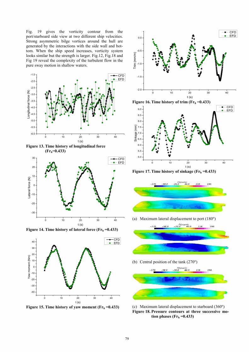
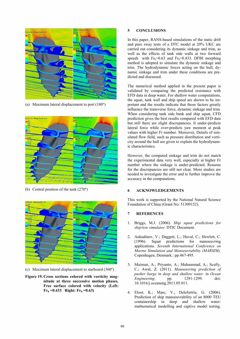
Fig. 19 gives the vorticity contour from the
port/starboard side view at two different ship velocities.
Strong asymmetric bilge vortices around the hull are
generated by the interactions with the side wall and bot-
tom. When the ship speed increases, vorticity system
looks similar but the strength is larger. Fig.12, Fig.18 and
Fig 19 reveal the complexity of the turbulent flow in the
pure sway motion in shallow waters.
Figure 13. Time history of longitudinal force
(Frh=0.433)
Figure 14. Time history of lateral force (Frh =0.433)
Figure 15. Time history of yaw moment (Frh =0.433)
Figure 16. Time history of trim (Frh =0.433)
Figure 17. Time history of sinkage (Frh =0.433)
(a) Maximum lateral displacement to port (180°)
(b) Central position of the tank (270°)
(c) Maximum lateral displacement to starboard (360°)
Figure 18. Pressure contours at three successive mo-
tion phases (Frh =0.433)
0 10 20 30 40
-6.0
-5.5
-5.0
-4.5
-4.0
-3.5
-3.0
-2.5
-2.0
-1.5
Lo
ng
itu
din
al fo
rce
(N
)
t (s)
CFD
EFD
0 10 20 30 40
-30
-20
-10
0
10
20
30
La
tera
l fo
rce
(N
)
t (s)
CFD
EFD
0 10 20 30 40
-40
-30
-20
-10
0
10
20
30
40
Ya
w m
om
en
t (N
m)
t (s)
CFD
EFD
0 10 20 30 40
-2.0
-1.5
-1.0
-0.5
0.0
Tri
m (
mm
/m)
t (s)
CFD
EFD
0 10 20 30 40
5.0
5.5
6.0
6.5
7.0
7.5
8.0
8.5
9.0
Sin
kag
e (
mm
)
t (s)
CFD
EFD
79
(a) Maximum lateral displacement to port (180°)
(b) Central position of the tank (270°)
(c) Maximum lateral displacement to starboard (360°)
Figure 19. Cross sections colored with vorticity mag-
nitude at three successive motion phases.
Free surface colored with velocity (Left:
Frh =0.433 Right: Frh =0.63)
5 CONCLUSIONS
In this paper, RANS-based simulations of the static drift
and pure sway tests of a DTC model at 20% UKC are
carried out considering its dynamic sinkage and trim, as
well as the effects of tank side walls at two forward
speeds with Frh=0.63 and Frh=0.433. DFBI morphing
method is adopted to simulate the dynamic sinkage and
trim. The hydrodynamic forces acting on the hull, dy-
namic sinkage and trim under these conditions are pre-
dicted and discussed.
The numerical method applied in the present paper is
validated by comparing the predicted resistance with
EFD data in deep water. For shallow water computations,
the squat, tank wall and ship speed are shown to be im-
portant and the results indicate that those factors greatly
influence the transverse force, dynamic sinkage and trim.
When considering tank side bank and ship squat, CFD
prediction gives the best results compared with EFD data
but still there are slight discrepancies. It under-predicts
lateral force while over-predicts yaw moment at peak
values with higher Fr number. Moreover, Details of sim-
ulated flow field, such as pressure distribution and vorti-
city around the hull are given to explain the hydrodynam-
ic characteristics.
However, the computed sinkage and trim do not match
the experimental data very well, especially at higher Fr
number where the sinkage is under-predicted. Reasons
for the discrepancies are still not clear. More studies are
needed to investigate the error and to further improve the
accuracy in the computations.
6 ACKNOWLEDGEMENTS
This work is supported by the National Natural Science
Foundation of China (Grant No: 51309152).
7 REFERENCES
1. Briggs, M.J. (2006). Ship squat predictions for
ship/tow simulator. DTIC Document.
2. Ankudinov, V.; Daggett, L.; Huval, C.; Hewlett, C.
(1996). Squat predictions for manoeuvring
applications. Seventh International Conference on
Marine Simulation and Manoeuvrability (MARSIM),
Copenhagen, Denmark.: pp.467-495.
3. Maimun, A.; Priyanto, A.; Muhammad, A.; Scully,
C.; Awal, Z. (2011). Manoeuvring prediction of
pusher barge in deep and shallow water. in Ocean
Engineering. pp. 1291-1299. doi:
10.1016/j.oceaneng.2011.05.011.
4. Eloot, K.; Marc, V.; Delefortrie, G. (2006).
Prediction of ship manoeuvrability of an 8000 TEU
containership in deep and shallow water:
mathematical modelling and captive model testing.
80
International Conference on Marine Simulation and
Ship Manoeuvring (MARSIM), Terschelling, The
Netherlands. pp.3-1.
5. Carrica, P.M.; Mofidi, A.; Eloot, K.; Delefortrie, G.
(2016). Direct simulation and experimental study of
zigzag maneuver of KCS in shallow water. Ocean
Engineering 112: pp. 117-133. doi:
10.1016/j.oceaneng.2015.12.008.
6. Tonelli, R.; Quadvlieg, F. (2015). New Benchmark
Data for Manoeuvring in Shallow Water Based on
Free Running Manoeuvring Tests Including
Uncertainty of the Results. Thirty-fourth
International Conference on Ocean, Offshore and
Arctic Engineering (OMAE), St. John’s,
Newfoundland, Canada.
7. Gourlay, T.P. (2014). ShallowFlow: A Program to
Model Ship Hydrodynamics in Shallow Water.
Thirty-third International Conference on Ocean,
Offshore and Arctic Engineering (OMAE), San
Francisco, California, USA. pp.V01AT01A018-
V01AT01A018.
8. Tuck, E. (1966). Shallow-water flows past slender
bodies. Journal of Fluid Mechanics 26(01): pp. 81-
95. doi: 10.1017/S0022112066001101.
9. SIMMAN (2008). Workshop on Verification and
Validation of Ship Manoeuvring Simulation
Methods, Copenhagen, Denmark.
10. SIMMAN (2014). Workshop on Verification and
Validation of Ship Manoeuvring Simulation
Methods, Copenhagen, Denmark.
11. Van Hoydonck, W.; Eloot, K. (2014). Shallow water
CFD computations for SIMMAN 2014. Workshop
on Verification and Validation of Ship Manoeuvring
Simulation Methods (SIMMAN), Copenhagen,
Denmark.
12. Böttner, C.-U.; Kastens, M.; Hirata, N.; Wasserbau,
B.F. (2014). Contribution to numerical Test Cases in
shallow water conditions. Workshop on Verification
and Validation of Ship Manoeuvring Simulation
Methods (SIMMAN), Copenhagen, Denmark.
13. Liu, X.; Wan, D. (2015). Numerical Simulation of
Ship Yaw Maneuvering in Deep and Shallow Water.
Twenty-fifth International Offshore and Polar
Engineering Conference (ISOPE), Kona, Hawaii,
USA.
14. Liu, X.; Fan, S.; Wang, J.; Wan, D. (2015).
Hydrodynamic Simulation of Pure Sway Tests with
Ship Speed and Water Depth Effects. Twenty-fifth
International Offshore and Polar Engineering
Conference (ISOPE), Kona, Hawaii, USA.
15. Simonsen, C.; Stern, F.; Agdrup, K. (2006). CFD
with PMM test validation for manoeuvring VLCC2
tanker in deep and shallow water. International
Conference on Marine Simulation and Ship
Manoeuvring (MARSIM), Terschelling, The
Netherlands.
16. Toxopeus, S.; Simonsen, C.; Guilmineau, E.;
Visonneau, M.; Xing, T.; Stern, F. (2013).
Investigation of water depth and basin wall effects
on KVLCC2 in manoeuvring motion using viscous-
flow calculations. Journal of Marine Science and
Technology 18(4): pp. 471-496. doi:
10.1007/s00773-013-0221-6.
17. Koop, A. (2015). Shallow Water Current Loads on a
LNG Carrier Using CFD. Thirty-fourth International
Conference on Ocean, Offshore and Arctic
Engineering (OMAE), St. John’s, Newfoundland,
Canada. American Society of Mechanical
Engineers.
18. Toxopeus, S.L. (2013). Viscous-flow calculations for
KVLCC2 in deep and shallow water. Fourth
International Conference on Computational Methods
in Marine Engineering (MARINE), Netherlands.
Springer: pp.151-169.
19. Eloot, K.; Marc, V.; Guillaume, D.; Evert, L. (2016).
Running Sinkage and Trim of the DTC Container
Carrier in Harmonic Sway and Yaw Motion: Open
Model Test Data for Validation Purposes. Fourth
International Conference on Ship Manoeuvring in
Shallow and Confined Water (MASHCON): Ship -
Bottom Interaction, Hamburg, Germany (to be
published).
20. Moctar, O.E.; Shigunov, V.; Zorn, T. (2012).
Duisburg Test Case: Post-panamax container ship for
benchmarking. Ship Technology Research 59(3): pp.
50-64. doi: 10.1179/str.2012.59.3.004.
8 AUTHORS’ BIOGRAPHIES
Yi Liu holds the current position of PhD student at
School of Naval Architecture, Ocean and Civil Engineer-
ing, Shanghai Jiao Tong University. Her previous experi-
ence includes numerical studies on the ship manoeuvring
in restricted waters, etc.
Zaojian Zou holds the current position of full professor
at School of Naval Architecture, Ocean and Civil Engi-
neering, Shanghai Jiao Tong University. He is responsi-
ble for teaching and research on marine hydrodynamics.
His previous experience includes PI of some projects on
manoeuvring and control of ships and other marine vehi-
cles. He was a member of the 22nd, 23rd, 25th and 26th
ITTC MC.
81
Lu Zou is a lecturer at School of Naval Architecture,
Ocean and Civil Engineering, Shanghai Jiao Tong Uni-
versity. Her major research interest is in the ship
manoeuvring in confined waters, as well as Verification
and Validation of CFD simulations.
82


![Cache Placement in Fog-RANs: From Centralized to ... · arXiv:1710.00784v1 [eess.SP] 10 Aug 2017 1 Cache Placement in Fog-RANs: From Centralized to Distributed Algorithms Juan Liu,](https://img.pdfslide.net/doc/110x75/5fc8ff00b0ee0a3d7341a413/cache-placement-in-fog-rans-from-centralized-to-arxiv171000784v1-eesssp.jpg)