Embed Size (px)
Citation preview
LiveAction Training Lab Workbook Pt.2

2 © Copyright 2018, LiveAction, Inc.
© Copyright 2018, LiveAction, Inc. All rights reserved. This product and related documentation are protected by copyright and distribution under licensing restricting their use, copy and distribution. No part of this document may be used or reproduced in any form or by any means, or stored in a database or retrieval system, without prior written permission of the publisher except in the case of brief quotations embodied in critical articles and reviews. Making copies of any part of this Training Material for any other purpose is in violation of United States copyright laws. While every precaution has been taken in the preparation of this document, LiveAction assumes no responsibility for errors or omissions. This document and features described herein are subject to change without notice. This LiveAction Training Material may not be sold by any company other than LiveAction without prior written permission. Neither LiveAction nor any authorized distributor or reseller shall be liable to the purchaser or any other person or entity with respect to any liability, loss, or damage caused or alleged to have been caused directly or indirectly by this material. Trademarks: LiveAction, its marks and logos, are registered trademarks of LiveAction, Inc. Other product and company names mentioned herein may be trademarks and/or registered trademarks of their respective companies. Specifications and descriptions subject to change without notice. All other products or services mentioned herein are trademarks or registered trademarks of their respective owners. Use of a term in this book should not be regarded as affecting the validity of any trademark or service mark. 2March2018
Table of Contents Lab 0: Setup and Get Connected .......................................................................................... 5 Lab 0.6: Connect to the Lab Network ....................................................................................... 6 Lab 0.7: Install Cisco AnyConnect ........................................................................................... 8 Lab 0.8: Connect to YOUR Pod ............................................................................................. 10 Lab 0.9: Install & Launch the LiveNX Client ........................................................................... 12 Lab 1: QoS Configuration .................................................................................................... 15 Lab 1.0: Introduction to QoS .................................................................................................. 16 Lab 1.1: Run Baseline Reports .............................................................................................. 18 Lab 1.2: Building Filters .......................................................................................................... 21 Lab 1.3: Validating Filters ....................................................................................................... 25 Lab 2: Classification & Marking .......................................................................................... 28 Lab 2.1: QoS Class Models .................................................................................................... 29 Lab 2.2: Validate DSCP Markings .......................................................................................... 30 Lab 2.3: Rouge DSCP Markings ............................................................................................ 34 Lab 2.4: Configure Classification & Marking Policies ............................................................. 35 Lab 2.5: Apply Marking Policies to Interface(s) ...................................................................... 43 Lab 2.6: Validate DSCP Settings ........................................................................................... 48 Lab 3: QoS Prioritization & Queueing ................................................................................ 50 Lab 3.0: Intro to Prioritization ................................................................................................. 51 Lab 3.1: Run the Reports! ...................................................................................................... 52 Lab 3.2: Building Queueing Policies ....................................................................................... 54 Lab 4: Shaping / Scaling ...................................................................................................... 59 Lab 4.0: Intro - Shaping (Scaling) ........................................................................................... 60 Lab 4.1: Shaping (Scaling) ..................................................................................................... 61 Lab 5: Throttling Traffic ....................................................................................................... 71 Lab 5.0: Intro - Throttling / Policing ........................................................................................ 72 Lab 5.1: Throttling / Policing ................................................................................................... 74 Lab 5.2: Confirm policing Settings .......................................................................................... 79 Lab 6: Buffer tuning ............................................................................................................. 80 Lab 6.0: Intro – Buffer Tuning ................................................................................................. 81 Lab 6.1: Implementing Tuning ................................................................................................ 85 Lab 7: QoS Alerts ................................................................................................................. 88 Lab 7.1: Configure QoS Alerts ............................................................................................... 89 Lab 8: Configure PfRv3 Monitoring .................................................................................... 95 Lab 8.1: Verify Traffic Generator ............................................................................................ 96 Lab 8.2: Discover Devices ...................................................................................................... 97 Lab 8.3: Configure Interfaces ............................................................................................... 102 Lab 8.4: Update Topology Map ............................................................................................ 105 Lab 8.5: Add CLI Access ...................................................................................................... 115 Lab 8.6: Configure NetFlow .................................................................................................. 121 Lab 8.7: Update Master Controller ....................................................................................... 129 Lab 8.8: Setup PfRv3 Filters ................................................................................................ 143 Lab 9: SD-WAN Troubleshooting ...................................................................................... 147 Lab 9.1: Monitor SD-WAN .................................................................................................... 148 Lab A: Appendix ................................................................................................................. 156 Lab A.1: Add Initial Device ................................................................................................... 157 Lab A.2: Using Device Discovery ......................................................................................... 165 Lab A.3: Export/Import Device Configuration ....................................................................... 172 Lab A.4: Saving Server Configurations ................................................................................ 175 Lab A.5: Connect via Remote Desktop Connection ............................................................. 176 Lab A.6: Search Alert History ............................................................................................... 178
4 © Copyright 2018, LiveAction, Inc.
IMPORTANT INFORMATION – Please Read! The step-by-step Labs in this Workbook have been written specifically for the LiveAction Training Student Pod, documented herein. All “Pods” have been pre-configured with the appropriate software and generated traffic to successfully perform these labs. Pay attention to any Notes presented as:
Note: This is a note example which gives additional information to the specific context.
The Diagrams, or screen shots, throughout this Workbook are examples for demonstration purposes and may not reflect the appropriate parameters for the classroom and/or your specific subnet. Unless specifically directed to do so, do not attempt to match the settings displayed in the screen shots to your configuration. Traffic collected by your assigned Pod may not be synchronized with other Student Pods, and in some cases… due to specific application traffic timing, may not display the exact result specified in the Labs. The main intent is to know HOW to access the information… not to attain specific lab results. Throughout this document italics, bold fonts, and words in CAPS, are used to place emphasis on specific procedures or results.
READ THE FOLLOWING NOTE!
Note: You should have already tested the installation, as well as your ability to connect to, Cisco’s dCloud sandbox using AnyConnect as directed in the course facilitation email. If you are unable to install, or connect via AnyConnect, you’ll need to work with your internal network or firewall support team to accomplish this. Your course Instructor has no way to facilitate a solution.
From the course facilitation email: “PRIOR to the class session, to assure that the VPN software is installed and working correctly, and that you may connect thru YOUR network security, each attendee needs to install AnyConnect and attempt to connect to: dcloud-rtp-anyconnect.cisco.com. Once presented with a login screen… that should prove that the install works, and that your network security will allow connections to our Online Lab Infrastructure. To perform additional testing (because sometimes the VPN prompt appears but your firewall still blocks the encrypted tunnel), please feel free to contact me and I can setup a time-frame and provide credentials to assure everything works.”
LiveAction Lab Workbook
5
Lab 0: Setup and Get Connected
6 © Copyright 2018, LiveAction, Inc.
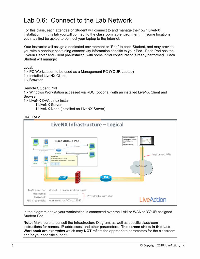
Lab 0.6: Connect to the Lab Network For this class, each attendee or Student will connect to and manage their own LiveNX installation. In this lab you will connect to the classroom lab environment. In some locations you may first be asked to connect your laptop to the Internet. Your instructor will assign a dedicated environment or “Pod” to each Student, and may provide you with a handout containing connectivity information specific to your Pod. Each Pod has the LiveNX Server and Client pre-installed, with some initial configuration already performed. Each Student will manage: Local: 1 x PC Workstation to be used as a Management PC (YOUR Laptop) 1 x Installed LiveNX Client 1 x Browser Remote Student Pod 1 x Windows Workstation accessed via RDC (optional) with an installed LiveNX Client and Browser 1 x LiveNX OVA Linux install
1 LiveNX Server 1 LiveNX Node (installed on LiveNX Server)
DIAGRAM
In the diagram above your workstation is connected over the LAN or WAN to YOUR assigned Student Pod.
Note: Make sure to consult the Infrastructure Diagram, as well as specific classroom instructions for names, IP addresses, and other parameters. The screen shots in this Lab Workbook are examples which may NOT reflect the appropriate parameters for the classroom and/or your specific subnet.
LiveAction Lab Workbook
7
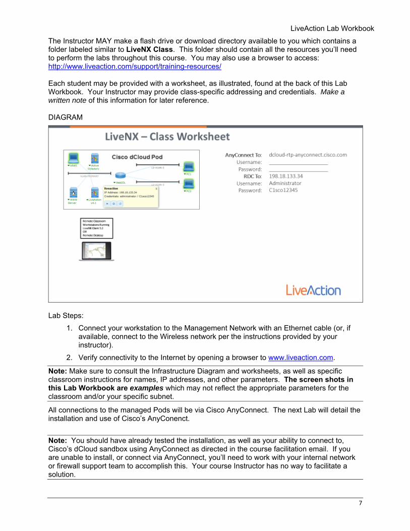
The Instructor MAY make a flash drive or download directory available to you which contains a folder labeled similar to LiveNX Class. This folder should contain all the resources you’ll need to perform the labs throughout this course. You may also use a browser to access: http://www.liveaction.com/support/training-resources/ Each student may be provided with a worksheet, as illustrated, found at the back of this Lab Workbook. Your Instructor may provide class-specific addressing and credentials. Make a written note of this information for later reference. DIAGRAM
Lab Steps:
1. Connect your workstation to the Management Network with an Ethernet cable (or, if available, connect to the Wireless network per the instructions provided by your instructor).
2. Verify connectivity to the Internet by opening a browser to www.liveaction.com.
Note: Make sure to consult the Infrastructure Diagram and worksheets, as well as specific classroom instructions for names, IP addresses, and other parameters. The screen shots in this Lab Workbook are examples which may not reflect the appropriate parameters for the classroom and/or your specific subnet.
All connections to the managed Pods will be via Cisco AnyConnect. The next Lab will detail the installation and use of Cisco’s AnyConenct.
Note: You should have already tested the installation, as well as your ability to connect to, Cisco’s dCloud sandbox using AnyConnect as directed in the course facilitation email. If you are unable to install, or connect via AnyConnect, you’ll need to work with your internal network or firewall support team to accomplish this. Your course Instructor has no way to facilitate a solution.
8 © Copyright 2018, LiveAction, Inc.
Lab 0.7: Install Cisco AnyConnect Cisco’s AnyConenct software provides a secure VPN connection to the resources hosted by Cisco on dCloud. After downloading & installing AnyConenct you will be able to access the resources contained in your Student Pod.
Note: If you already have AnyConnect loaded on your PC, you may need to work with your internal support team to allow its use to multiple destinations.
Use the following links to download the AnyConnect Software as appropriate: AnyConnect - Windows Client http://cdnx.liveaction.com/LiveNX-Training/anyconnect-win-3.1.14018-pre-deploy-k9.msi AnyConnect - Mac Client - Cisco Notes on Mac-Client installation https://liveaction.box.com/s/j33tjvp7dnpnt9o4iascg5jyh48yu5tc Installing the VPN software
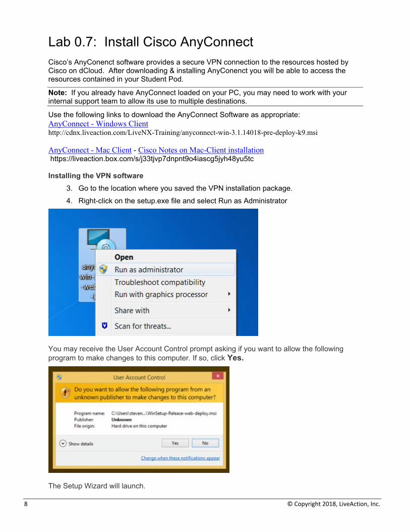
3. Go to the location where you saved the VPN installation package. 4. Right-click on the setup.exe file and select Run as Administrator
You may receive the User Account Control prompt asking if you want to allow the following program to make changes to this computer. If so, click Yes.
The Setup Wizard will launch.
LiveAction Lab Workbook
9
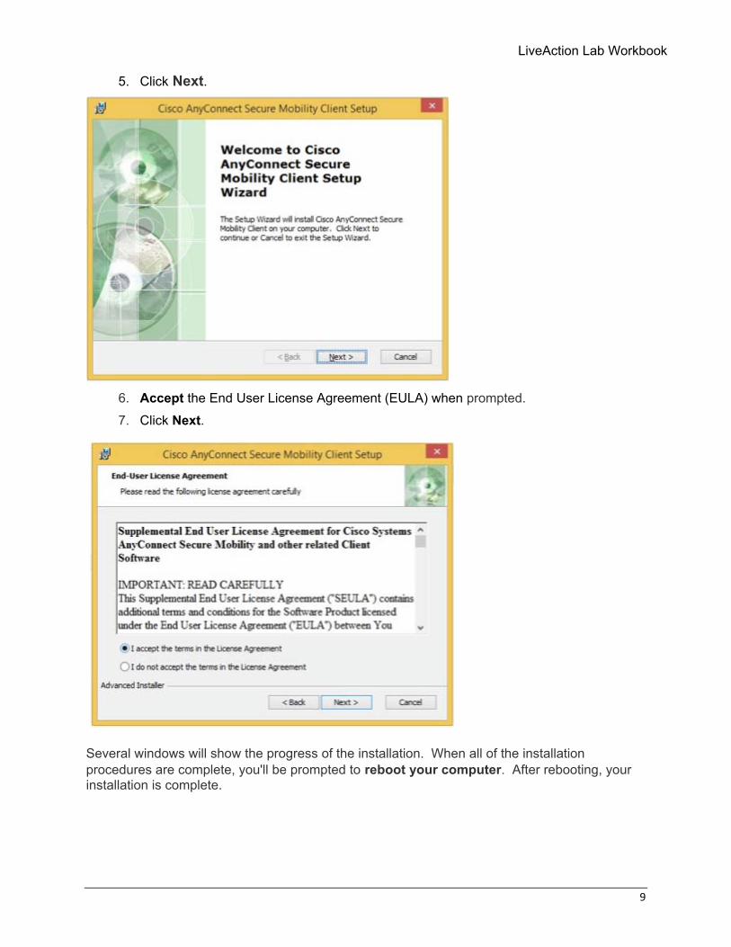
5. Click Next.
6. Accept the End User License Agreement (EULA) when prompted. 7. Click Next.
Several windows will show the progress of the installation. When all of the installation procedures are complete, you'll be prompted to reboot your computer. After rebooting, your installation is complete.
10 © Copyright 2018, LiveAction, Inc.
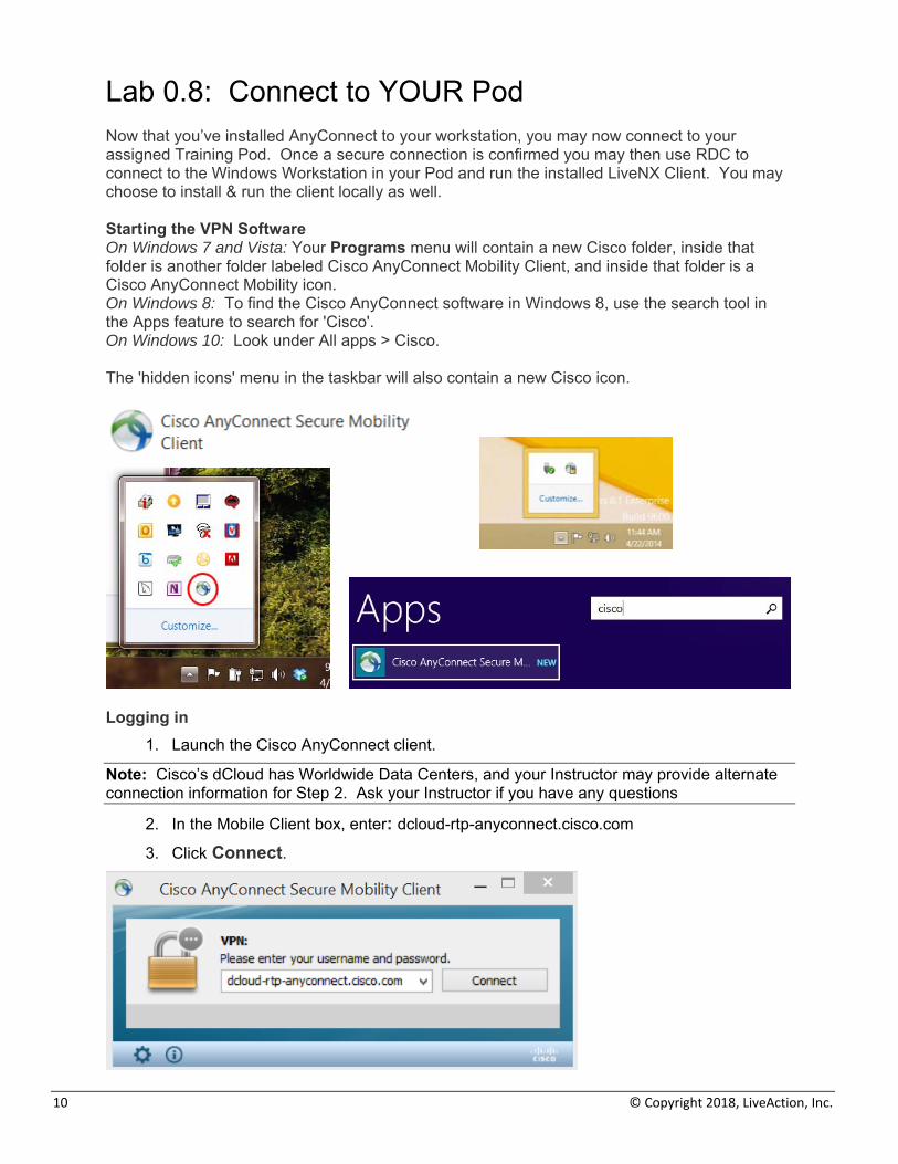
Lab 0.8: Connect to YOUR Pod Now that you’ve installed AnyConnect to your workstation, you may now connect to your assigned Training Pod. Once a secure connection is confirmed you may then use RDC to connect to the Windows Workstation in your Pod and run the installed LiveNX Client. You may choose to install & run the client locally as well. Starting the VPN Software On Windows 7 and Vista: Your Programs menu will contain a new Cisco folder, inside that folder is another folder labeled Cisco AnyConnect Mobility Client, and inside that folder is a Cisco AnyConnect Mobility icon. On Windows 8: To find the Cisco AnyConnect software in Windows 8, use the search tool in the Apps feature to search for 'Cisco'. On Windows 10: Look under All apps > Cisco. The 'hidden icons' menu in the taskbar will also contain a new Cisco icon.
Logging in
1. Launch the Cisco AnyConnect client.
Note: Cisco’s dCloud has Worldwide Data Centers, and your Instructor may provide alternate connection information for Step 2. Ask your Instructor if you have any questions
2. In the Mobile Client box, enter: dcloud-rtp-anyconnect.cisco.com
3. Click Connect.
LiveAction Lab Workbook
11
Note: If you already have AnyConnect loaded on your PC, you may need to work with your internal support team to allow its use to multiple destinations.
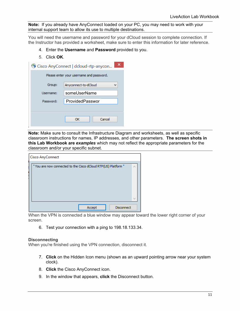
You will need the username and password for your dCloud session to complete connection. If the Instructor has provided a worksheet, make sure to enter this information for later reference.
4. Enter the Username and Password provided to you. 5. Click OK.
Note: Make sure to consult the Infrastructure Diagram and worksheets, as well as specific classroom instructions for names, IP addresses, and other parameters. The screen shots in this Lab Workbook are examples which may not reflect the appropriate parameters for the classroom and/or your specific subnet.
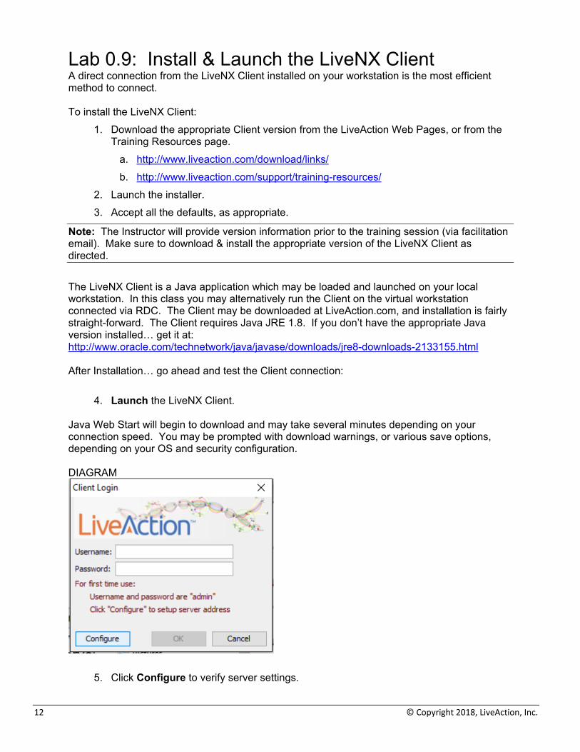
When the VPN is connected a blue window may appear toward the lower right corner of your screen.
6. Test your connection with a ping to 198.18.133.34.
Disconnecting When you're finished using the VPN connection, disconnect it.
7. Click on the Hidden Icon menu (shown as an upward pointing arrow near your system clock).
8. Click the Cisco AnyConnect icon. 9. In the window that appears, click the Disconnect button.
someUserName
ProvidedPasswor
12 © Copyright 2018, LiveAction, Inc.
Lab 0.9: Install & Launch the LiveNX Client A direct connection from the LiveNX Client installed on your workstation is the most efficient method to connect. To install the LiveNX Client:
1. Download the appropriate Client version from the LiveAction Web Pages, or from the Training Resources page.
a. http://www.liveaction.com/download/links/ b. http://www.liveaction.com/support/training-resources/
2. Launch the installer. 3. Accept all the defaults, as appropriate.
Note: The Instructor will provide version information prior to the training session (via facilitation email). Make sure to download & install the appropriate version of the LiveNX Client as directed.
The LiveNX Client is a Java application which may be loaded and launched on your local workstation. In this class you may alternatively run the Client on the virtual workstation connected via RDC. The Client may be downloaded at LiveAction.com, and installation is fairly straight-forward. The Client requires Java JRE 1.8. If you don’t have the appropriate Java version installed… get it at: http://www.oracle.com/technetwork/java/javase/downloads/jre8-downloads-2133155.html After Installation… go ahead and test the Client connection:
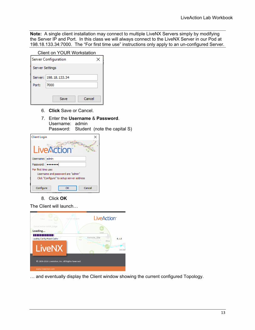
4. Launch the LiveNX Client. Java Web Start will begin to download and may take several minutes depending on your connection speed. You may be prompted with download warnings, or various save options, depending on your OS and security configuration. DIAGRAM
5. Click Configure to verify server settings.
LiveAction Lab Workbook
13
Note: A single client installation may connect to multiple LiveNX Servers simply by modifying the Server IP and Port. In this class we will always connect to the LiveNX Server in our Pod at 198.18.133.34:7000. The “For first time use” instructions only apply to an un-configured Server.
Client on YOUR Workstation
6. Click Save or Cancel. 7. Enter the Username & Password.
Username: admin Password: Student (note the capital S)
8. Click OK
The Client will launch…
… and eventually display the Client window showing the current configured Topology.

14 © Copyright 2018, LiveAction, Inc.
LiveAction Lab Workbook
15
Lab 1: QoS Configuration
16 © Copyright 2018, LiveAction, Inc.
Lab 1.0: Introduction to QoS In this lab we are going to walk through the story of implementing QoS for a small WAN network using LiveNX. When complete we will have used LiveNX to:
• Identify and validate critical traffic is marked with a DSCP tag • Build Shaping Policies • Prioritize Voice & Video • Protect high priority data • Police scavenger/low priority traffic • Validated QoS is working end-to-end
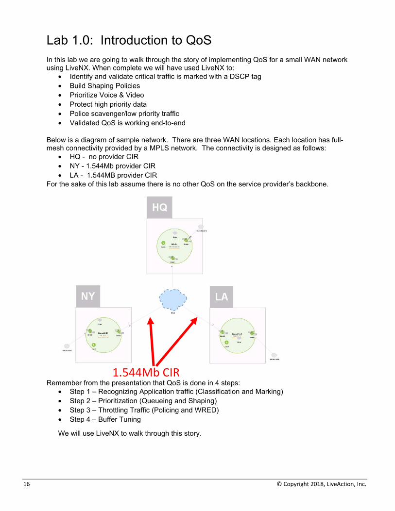
Below is a diagram of sample network. There are three WAN locations. Each location has full-mesh connectivity provided by a MPLS network. The connectivity is designed as follows:
• HQ - no provider CIR • NY - 1.544Mb provider CIR • LA - 1.544MB provider CIR
For the sake of this lab assume there is no other QoS on the service provider’s backbone.
Remember from the presentation that QoS is done in 4 steps:
• Step 1 – Recognizing Application traffic (Classification and Marking) • Step 2 – Prioritization (Queueing and Shaping) • Step 3 – Throttling Traffic (Policing and WRED) • Step 4 – Buffer Tuning
We will use LiveNX to walk through this story.
1.544Mb CIR
LiveAction Lab Workbook
17
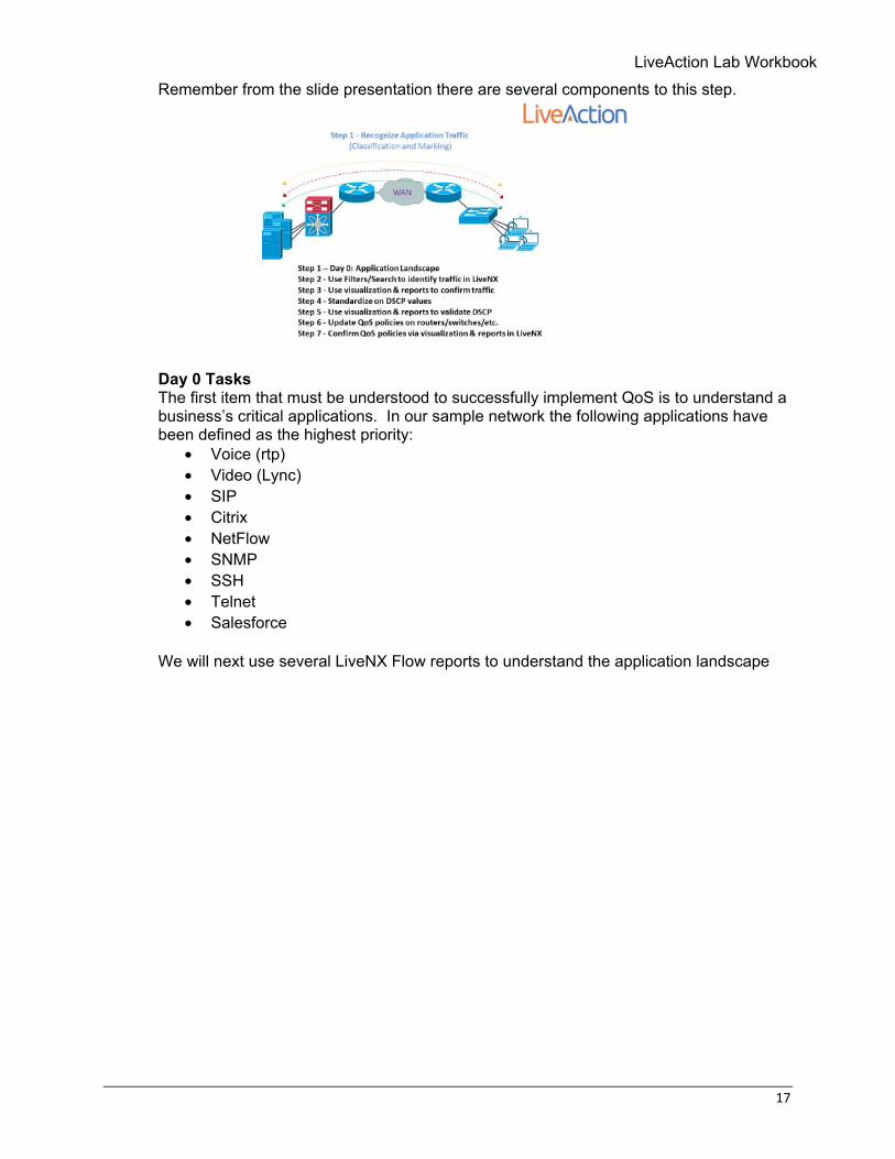
Remember from the slide presentation there are several components to this step.
Day 0 Tasks The first item that must be understood to successfully implement QoS is to understand a business’s critical applications. In our sample network the following applications have been defined as the highest priority:
• Voice (rtp) • Video (Lync) • SIP • Citrix • NetFlow • SNMP • SSH • Telnet • Salesforce
We will next use several LiveNX Flow reports to understand the application landscape
18 © Copyright 2018, LiveAction, Inc.
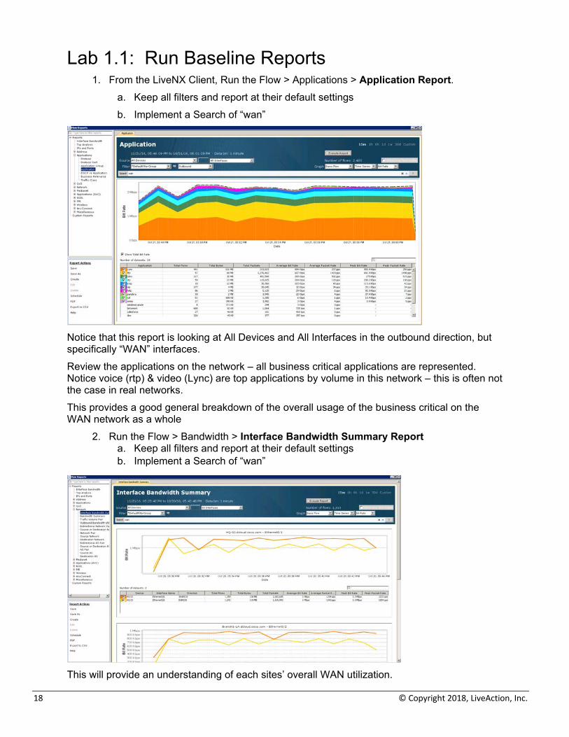
Lab 1.1: Run Baseline Reports 1. From the LiveNX Client, Run the Flow > Applications > Application Report.
a. Keep all filters and report at their default settings b. Implement a Search of “wan”
Notice that this report is looking at All Devices and All Interfaces in the outbound direction, but specifically “WAN” interfaces. Review the applications on the network – all business critical applications are represented. Notice voice (rtp) & video (Lync) are top applications by volume in this network – this is often not the case in real networks. This provides a good general breakdown of the overall usage of the business critical on the WAN network as a whole
2. Run the Flow > Bandwidth > Interface Bandwidth Summary Report a. Keep all filters and report at their default settings b. Implement a Search of “wan”
This will provide an understanding of each sites’ overall WAN utilization.
LiveAction Lab Workbook
19
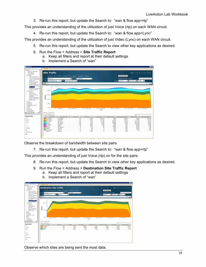
3. Re-run this report, but update the Search to: “wan & flow.app=rtp” This provides an understanding of the utilization of just Voice (rtp) on each WAN circuit.
4. Re-run this report, but update the Search to: “wan & flow.app=Lync” This provides an understanding of the utilization of just Video (Lync) on each WAN circuit.
5. Re-run this report, but update the Search to view other key applications as desired. 6. Run the Flow > Address > Site Traffic Report
a. Keep all filters and report at their default settings b. Implement a Search of “wan”
Observe the breakdown of bandwidth between site pairs.
7. Re-run this report, but update the Search to: “wan & flow.app=rtp” This provides an understanding of just Voice (rtp) on for the site pairs.
8. Re-run this report, but update the Search to view other key applications as desired. 9. Run the Flow > Address > Destination Site Traffic Report
a. Keep all filters and report at their default settings b. Implement a Search of “wan”
Observe which sites are being sent the most data.
20 © Copyright 2018, LiveAction, Inc.
10. Re-run this report, but update the Search to: “wan & flow.app=rtp” This provides an understanding of which sites are receiving the most Voice (rtp).
11. Re-run this report, but update the Search to view other key applications as desired.
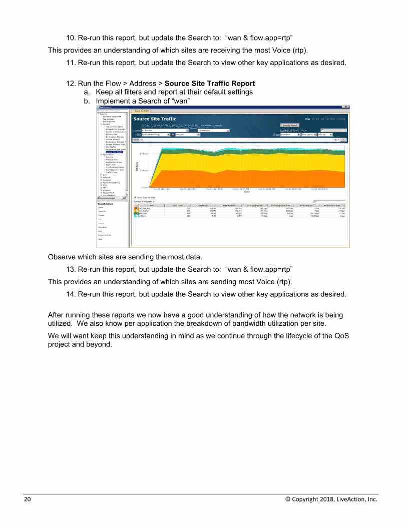
12. Run the Flow > Address > Source Site Traffic Report a. Keep all filters and report at their default settings b. Implement a Search of “wan”
Observe which sites are sending the most data.
13. Re-run this report, but update the Search to: “wan & flow.app=rtp” This provides an understanding of which sites are sending most Voice (rtp).
14. Re-run this report, but update the Search to view other key applications as desired.
After running these reports we now have a good understanding of how the network is being utilized. We also know per application the breakdown of bandwidth utilization per site. We will want keep this understanding in mind as we continue through the lifecycle of the QoS project and beyond.
LiveAction Lab Workbook
21
Lab 1.2: Building Filters The reports we have used so far were using NBAR for recognizing specific types of traffic such as Voice (rtp) or Video (Lync). This can be an excellent way to see specific applications that are known by NBAR. In real networks though, NBAR is a great, but not a perfect solution for recognizing traffic. Often, one may see multiple different NBAR definitions for the same type of application (cisco-phone-audio and cisco-jabber-audio) if no NBAR Protocol Pack standardization has occurred or NBAR will return unknown results if Protocol Packs are old. Many networks have not yet adopted NBAR so this data is unavailable, as well. To overcome these challenges with recognizing specific applications of interest, LiveNX Filters provide an excellent way to administratively define application definitions. As an example, we are now going to build a filter in LiveNX that could be used for recognizing a Cisco CallManager IP Phone system. This is just one example. In a real network the concepts presented should be repeated for other applications of interest on the network. Lab Steps:
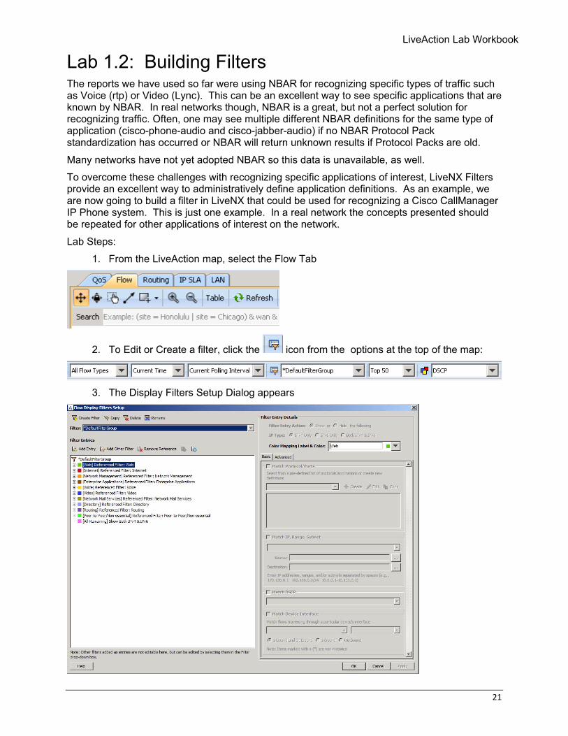
1. From the LiveAction map, select the Flow Tab
2. To Edit or Create a filter, click the icon from the options at the top of the map:
3. The Display Filters Setup Dialog appears
22 © Copyright 2018, LiveAction, Inc.
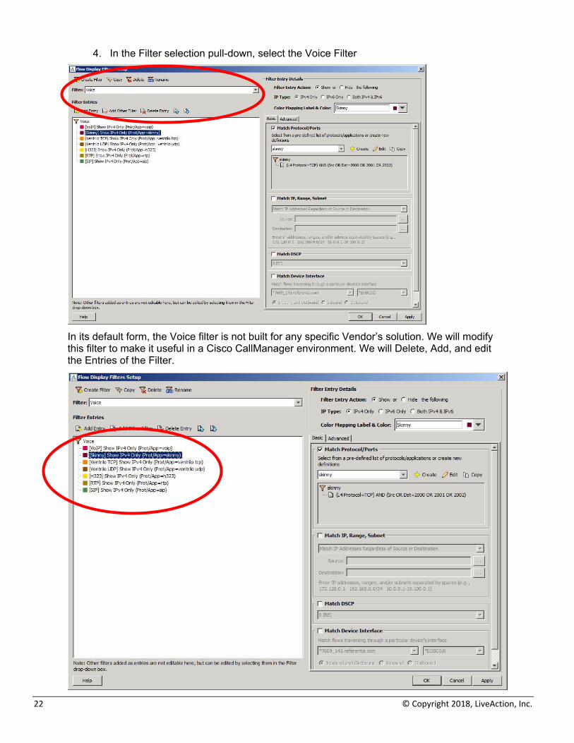
4. In the Filter selection pull-down, select the Voice Filter
In its default form, the Voice filter is not built for any specific Vendor’s solution. We will modify this filter to make it useful in a Cisco CallManager environment. We will Delete, Add, and edit the Entries of the Filter.
LiveAction Lab Workbook
23
5. Delete unused Entries a. VoIP b. Ventrilo TCP c. Ventrilo UDP
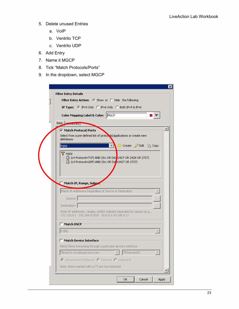
6. Add Entry 7. Name it MGCP 8. Tick “Match Protocols/Ports” 9. In the dropdown, select MGCP
24 © Copyright 2018, LiveAction, Inc.
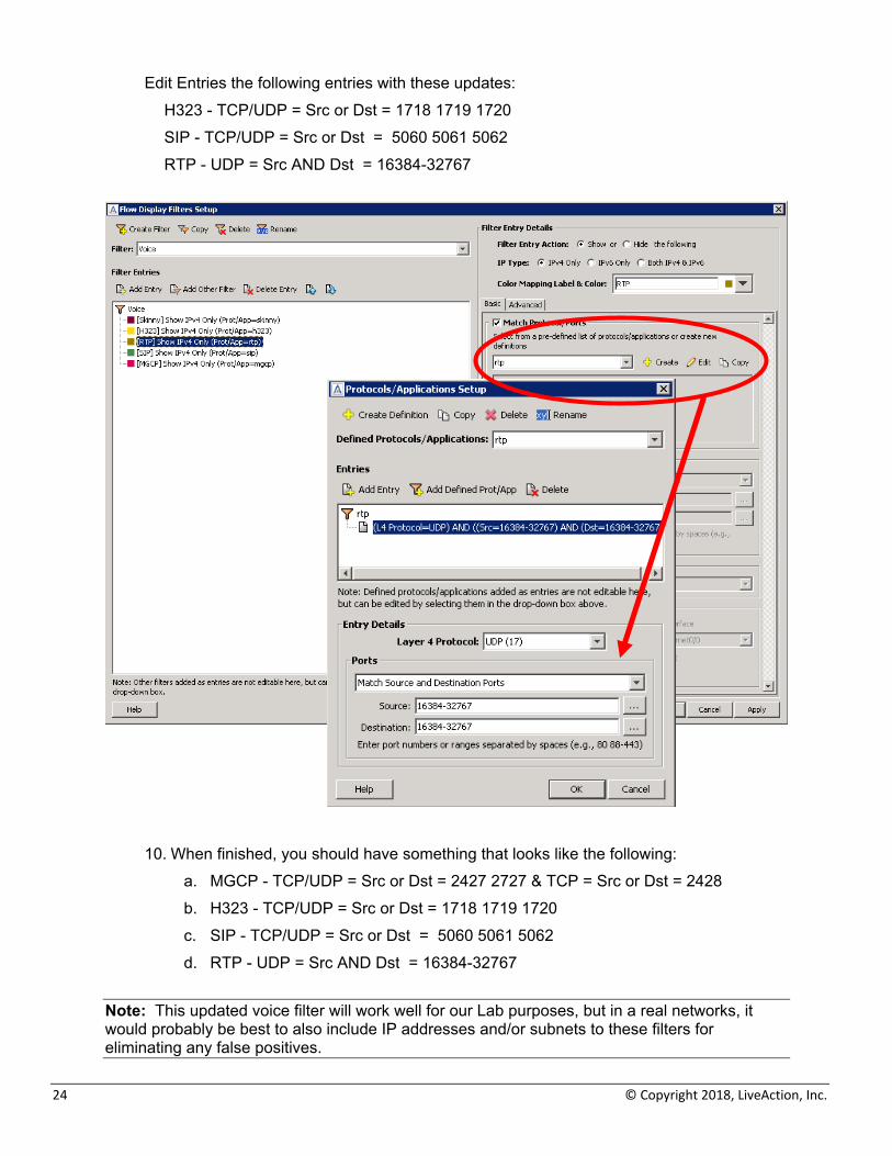
Edit Entries the following entries with these updates: H323 - TCP/UDP = Src or Dst = 1718 1719 1720 SIP - TCP/UDP = Src or Dst = 5060 5061 5062 RTP - UDP = Src AND Dst = 16384-32767
10. When finished, you should have something that looks like the following: a. MGCP - TCP/UDP = Src or Dst = 2427 2727 & TCP = Src or Dst = 2428 b. H323 - TCP/UDP = Src or Dst = 1718 1719 1720 c. SIP - TCP/UDP = Src or Dst = 5060 5061 5062 d. RTP - UDP = Src AND Dst = 16384-32767
Note: This updated voice filter will work well for our Lab purposes, but in a real networks, it would probably be best to also include IP addresses and/or subnets to these filters for eliminating any false positives.
LiveAction Lab Workbook
25
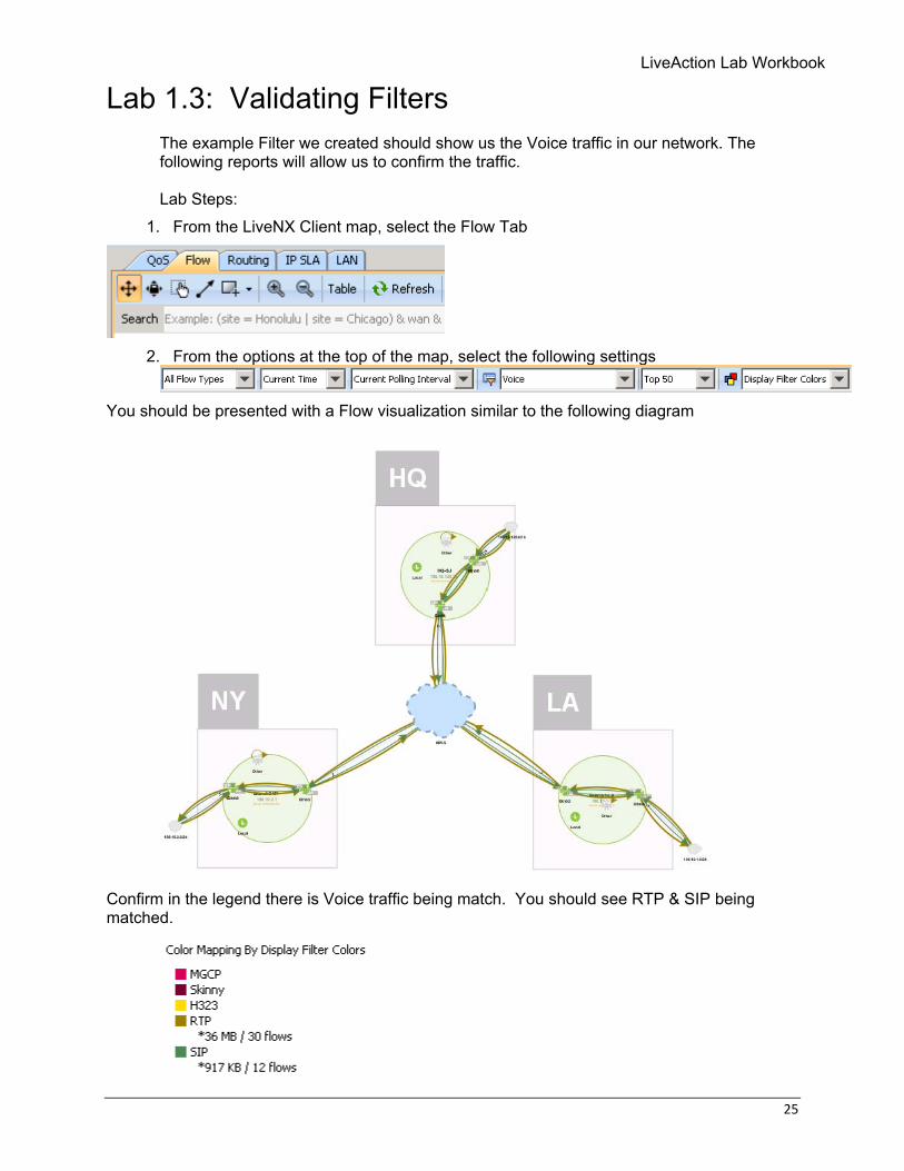
Lab 1.3: Validating Filters The example Filter we created should show us the Voice traffic in our network. The following reports will allow us to confirm the traffic. Lab Steps:
1. From the LiveNX Client map, select the Flow Tab
2. From the options at the top of the map, select the following settings
You should be presented with a Flow visualization similar to the following diagram
Confirm in the legend there is Voice traffic being match. You should see RTP & SIP being matched.
26 © Copyright 2018, LiveAction, Inc.
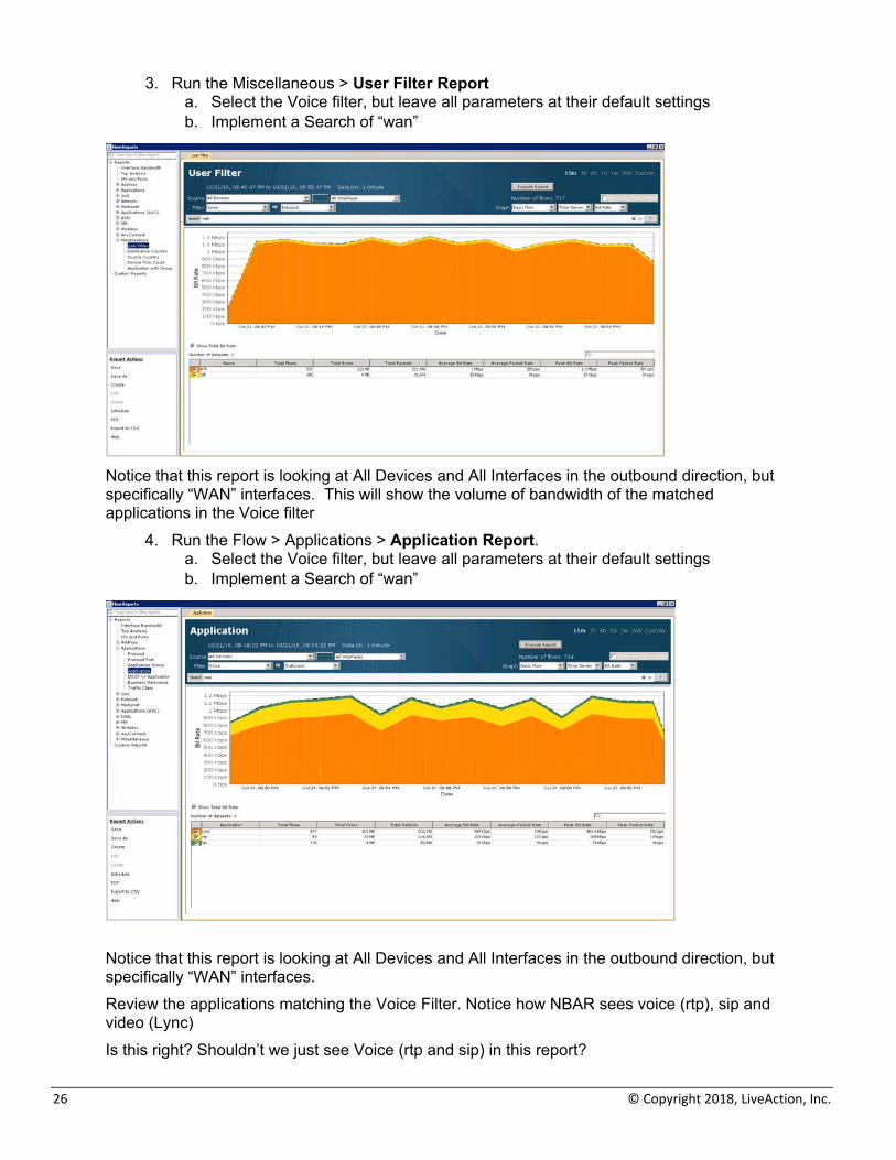
3. Run the Miscellaneous > User Filter Report a. Select the Voice filter, but leave all parameters at their default settings b. Implement a Search of “wan”
Notice that this report is looking at All Devices and All Interfaces in the outbound direction, but specifically “WAN” interfaces. This will show the volume of bandwidth of the matched applications in the Voice filter
4. Run the Flow > Applications > Application Report. a. Select the Voice filter, but leave all parameters at their default settings b. Implement a Search of “wan”
Notice that this report is looking at All Devices and All Interfaces in the outbound direction, but specifically “WAN” interfaces. Review the applications matching the Voice Filter. Notice how NBAR sees voice (rtp), sip and video (Lync) Is this right? Shouldn’t we just see Voice (rtp and sip) in this report?
LiveAction Lab Workbook
27
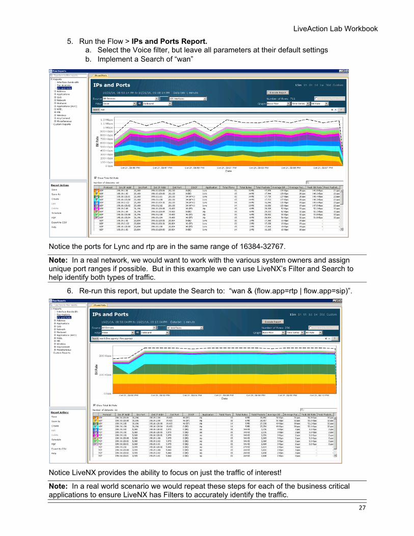
5. Run the Flow > IPs and Ports Report. a. Select the Voice filter, but leave all parameters at their default settings b. Implement a Search of “wan”
Notice the ports for Lync and rtp are in the same range of 16384-32767.
Note: In a real network, we would want to work with the various system owners and assign unique port ranges if possible. But in this example we can use LiveNX’s Filter and Search to help identify both types of traffic.
6. Re-run this report, but update the Search to: “wan & (flow.app=rtp | flow.app=sip)”.
Notice LiveNX provides the ability to focus on just the traffic of interest!
Note: In a real world scenario we would repeat these steps for each of the business critical applications to ensure LiveNX has Filters to accurately identify the traffic.

28 © Copyright 2018, LiveAction, Inc.
Lab 2: Classification & Marking
LiveAction Lab Workbook
29
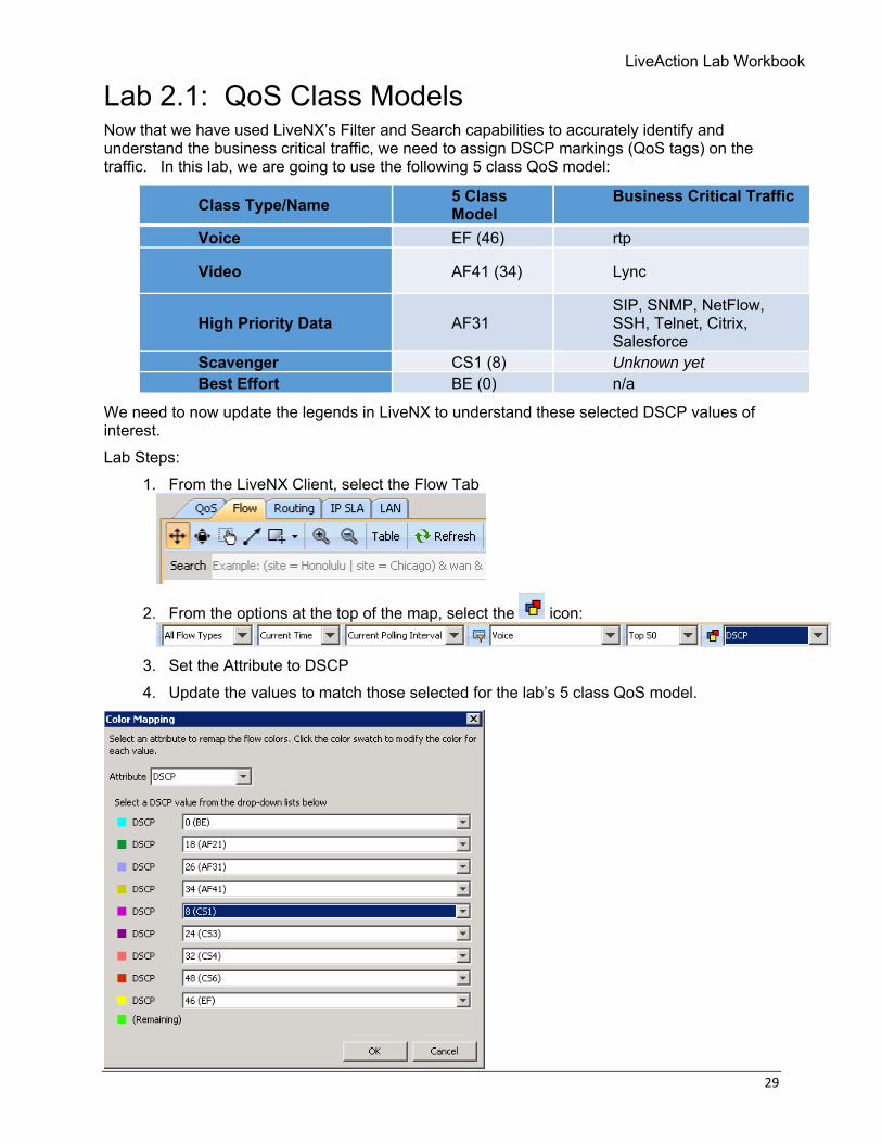
Lab 2.1: QoS Class Models Now that we have used LiveNX’s Filter and Search capabilities to accurately identify and understand the business critical traffic, we need to assign DSCP markings (QoS tags) on the traffic. In this lab, we are going to use the following 5 class QoS model:
Class Type/Name 5 Class Model
Business Critical Traffic
Voice EF (46) rtp
Video AF41 (34) Lync
High Priority Data AF31 SIP, SNMP, NetFlow, SSH, Telnet, Citrix, Salesforce
Scavenger CS1 (8) Unknown yet Best Effort BE (0) n/a
We need to now update the legends in LiveNX to understand these selected DSCP values of interest. Lab Steps:
1. From the LiveNX Client, select the Flow Tab
2. From the options at the top of the map, select the icon:
3. Set the Attribute to DSCP 4. Update the values to match those selected for the lab’s 5 class QoS model.
30 © Copyright 2018, LiveAction, Inc.
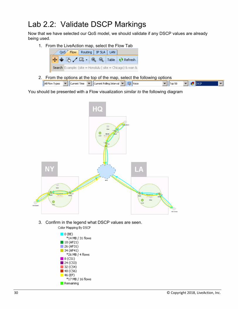
Lab 2.2: Validate DSCP Markings Now that we have selected our QoS model, we should validate if any DSCP values are already being used.
1. From the LiveAction map, select the Flow Tab
2. From the options at the top of the map, select the following options
You should be presented with a Flow visualization similar to the following diagram
3. Confirm in the legend what DSCP values are seen.
LiveAction Lab Workbook
31
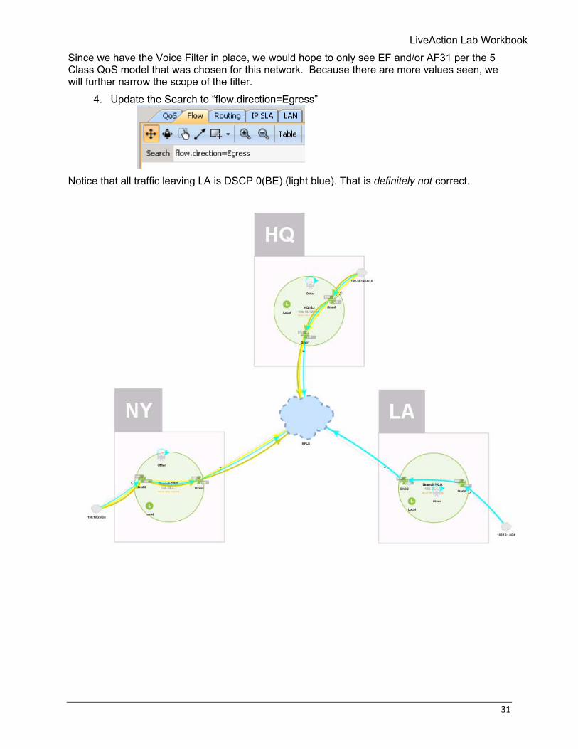
Since we have the Voice Filter in place, we would hope to only see EF and/or AF31 per the 5 Class QoS model that was chosen for this network. Because there are more values seen, we will further narrow the scope of the filter.
4. Update the Search to “flow.direction=Egress”
Notice that all traffic leaving LA is DSCP 0(BE) (light blue). That is definitely not correct.
32 © Copyright 2018, LiveAction, Inc.
We’ll use LiveNX Client reports to investigate further. 5. Run the QoS > DSCP Report
a. Select the Voice filter, but leave all parameters at their default settings b. Implement a Search of “wan”
Notice that this report is looking at All Devices and All Interfaces in the outbound direction, but specifically “WAN” interfaces. This report is good to show the overall bandwidth of Voice traffic in the network and the percent of Voice bandwidth that is / is not marked as desired.
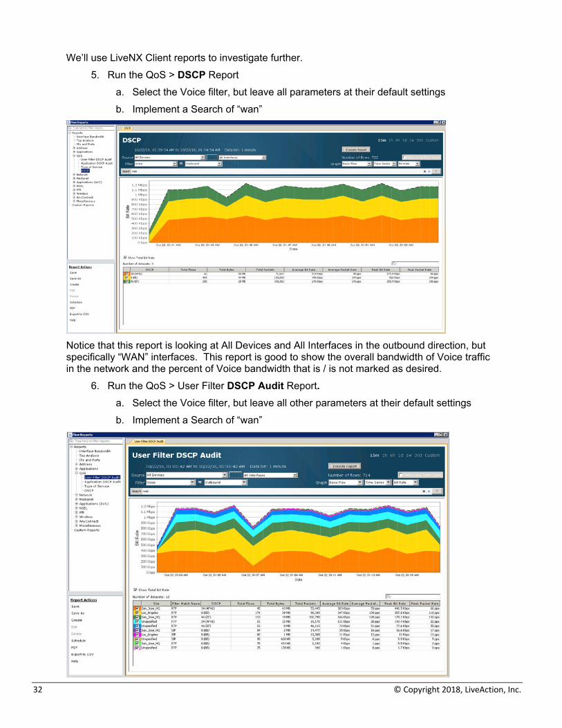
6. Run the QoS > User Filter DSCP Audit Report. a. Select the Voice filter, but leave all other parameters at their default settings b. Implement a Search of “wan”
LiveAction Lab Workbook
33
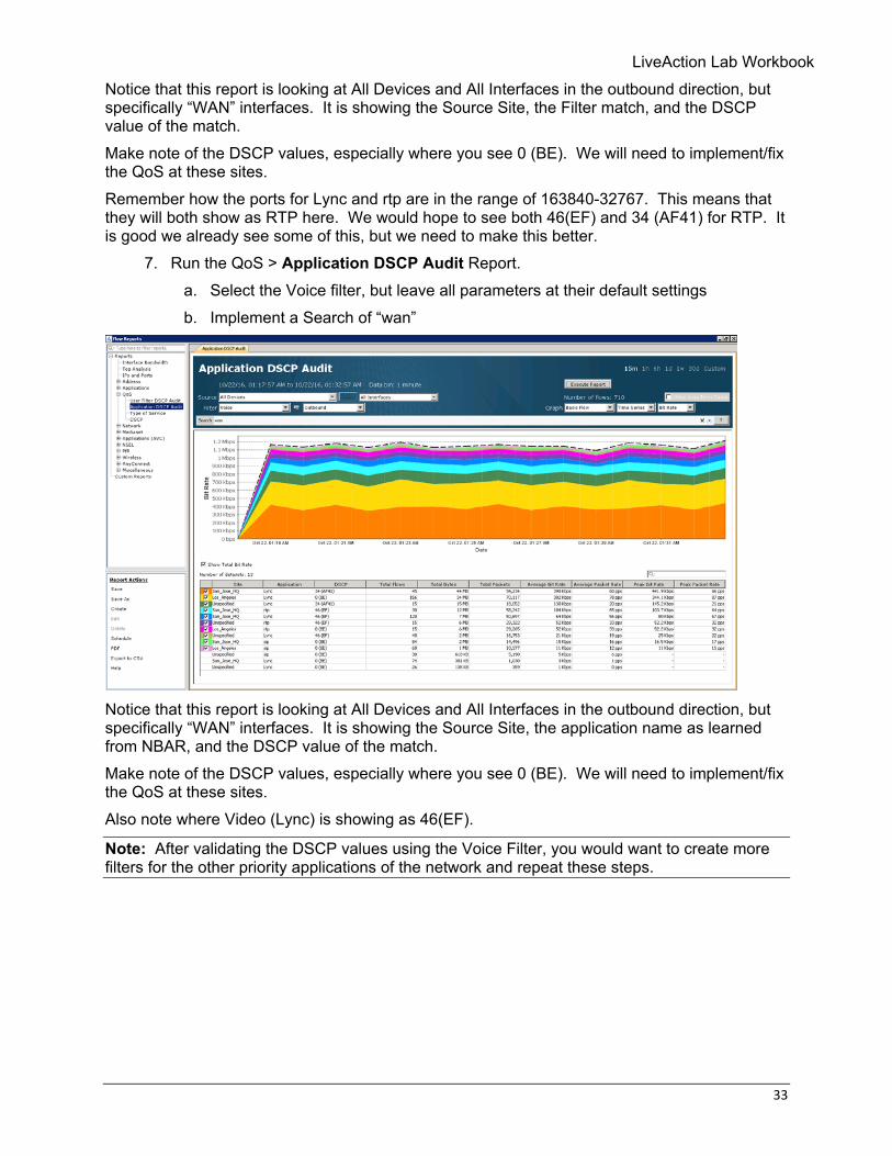
Notice that this report is looking at All Devices and All Interfaces in the outbound direction, but specifically “WAN” interfaces. It is showing the Source Site, the Filter match, and the DSCP value of the match. Make note of the DSCP values, especially where you see 0 (BE). We will need to implement/fix the QoS at these sites. Remember how the ports for Lync and rtp are in the range of 163840-32767. This means that they will both show as RTP here. We would hope to see both 46(EF) and 34 (AF41) for RTP. It is good we already see some of this, but we need to make this better.
7. Run the QoS > Application DSCP Audit Report. a. Select the Voice filter, but leave all parameters at their default settings b. Implement a Search of “wan”
Notice that this report is looking at All Devices and All Interfaces in the outbound direction, but specifically “WAN” interfaces. It is showing the Source Site, the application name as learned from NBAR, and the DSCP value of the match. Make note of the DSCP values, especially where you see 0 (BE). We will need to implement/fix the QoS at these sites. Also note where Video (Lync) is showing as 46(EF).
Note: After validating the DSCP values using the Voice Filter, you would want to create more filters for the other priority applications of the network and repeat these steps.
34 © Copyright 2018, LiveAction, Inc.
Lab 2.3: Rouge DSCP Markings We will also want to ensure that any non-priority traffic is not accidently or maliciously given a high priority DSCP value. Lab Steps:
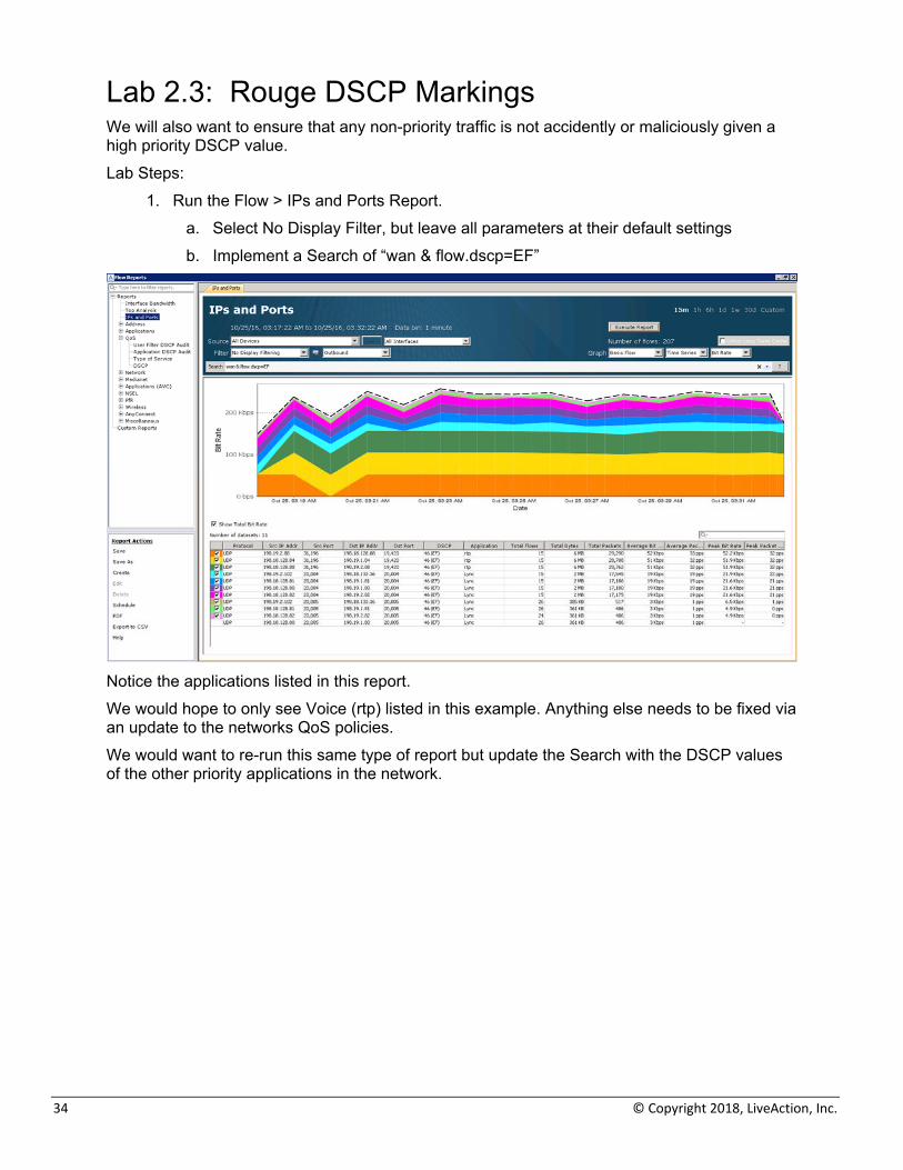
1. Run the Flow > IPs and Ports Report. a. Select No Display Filter, but leave all parameters at their default settings b. Implement a Search of “wan & flow.dscp=EF”
Notice the applications listed in this report. We would hope to only see Voice (rtp) listed in this example. Anything else needs to be fixed via an update to the networks QoS policies. We would want to re-run this same type of report but update the Search with the DSCP values of the other priority applications in the network.
LiveAction Lab Workbook
35
Lab 2.4: Configure Classification & Marking Policies Now that we understand the traffic of the network and the DSCP values that should be marked on each type of traffic, we can use LiveNX to implement the correct QoS policies to the traffic on the routers. We will create a template QoS policy and apply this to the LAN interface of each of the routers to classify and mark the priority traffic properly. Lab Steps:
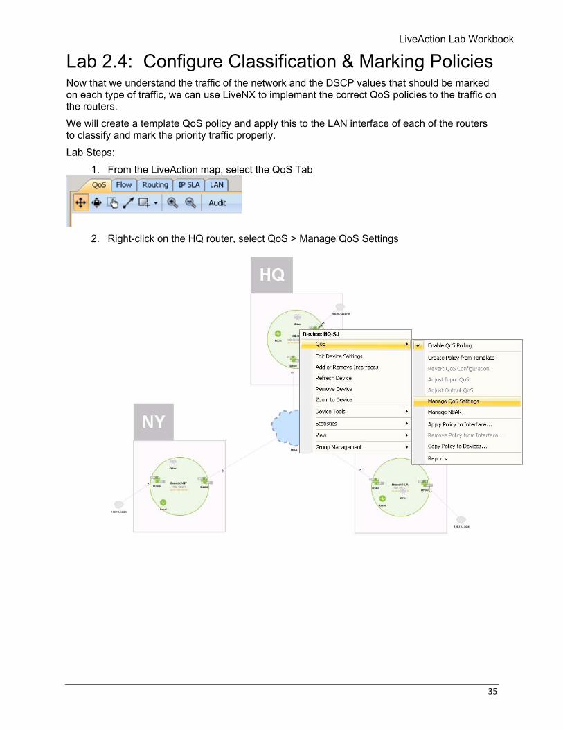
1. From the LiveAction map, select the QoS Tab
2. Right-click on the HQ router, select QoS > Manage QoS Settings
36 © Copyright 2018, LiveAction, Inc.
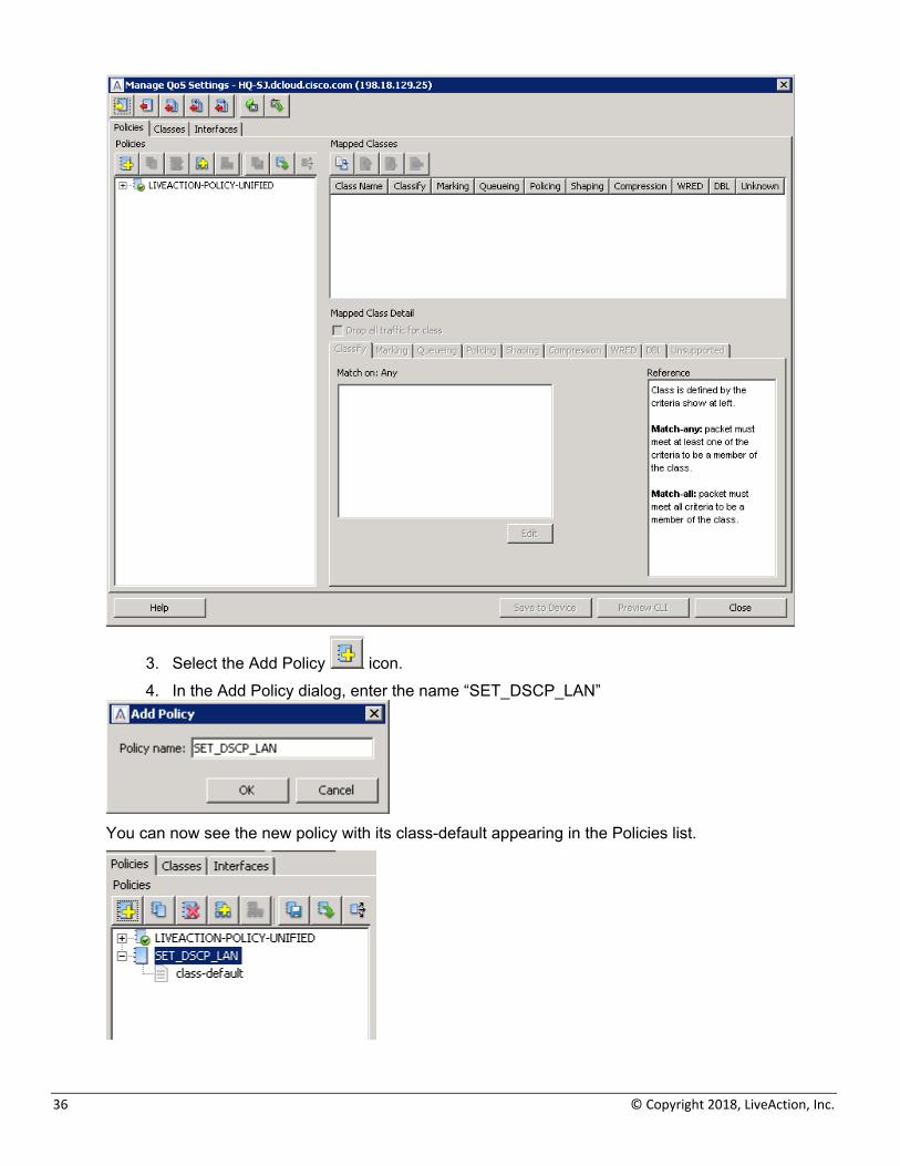
3. Select the Add Policy icon. 4. In the Add Policy dialog, enter the name “SET_DSCP_LAN”
You can now see the new policy with its class-default appearing in the Policies list.
LiveAction Lab Workbook
37
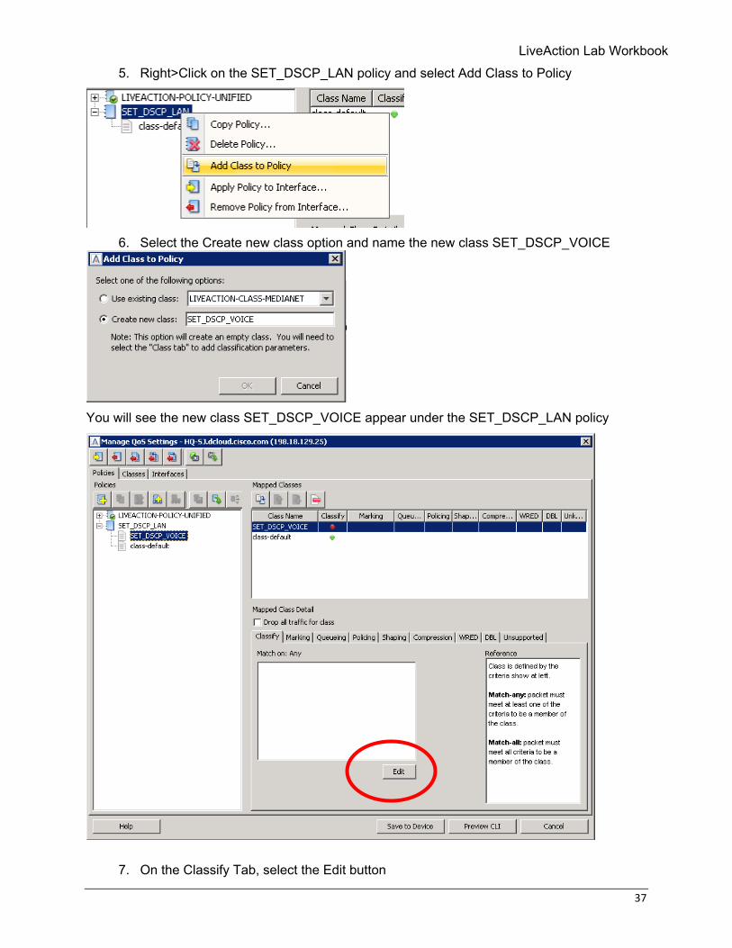
5. Right>Click on the SET_DSCP_LAN policy and select Add Class to Policy
6. Select the Create new class option and name the new class SET_DSCP_VOICE
You will see the new class SET_DSCP_VOICE appear under the SET_DSCP_LAN policy
7. On the Classify Tab, select the Edit button
38 © Copyright 2018, LiveAction, Inc.
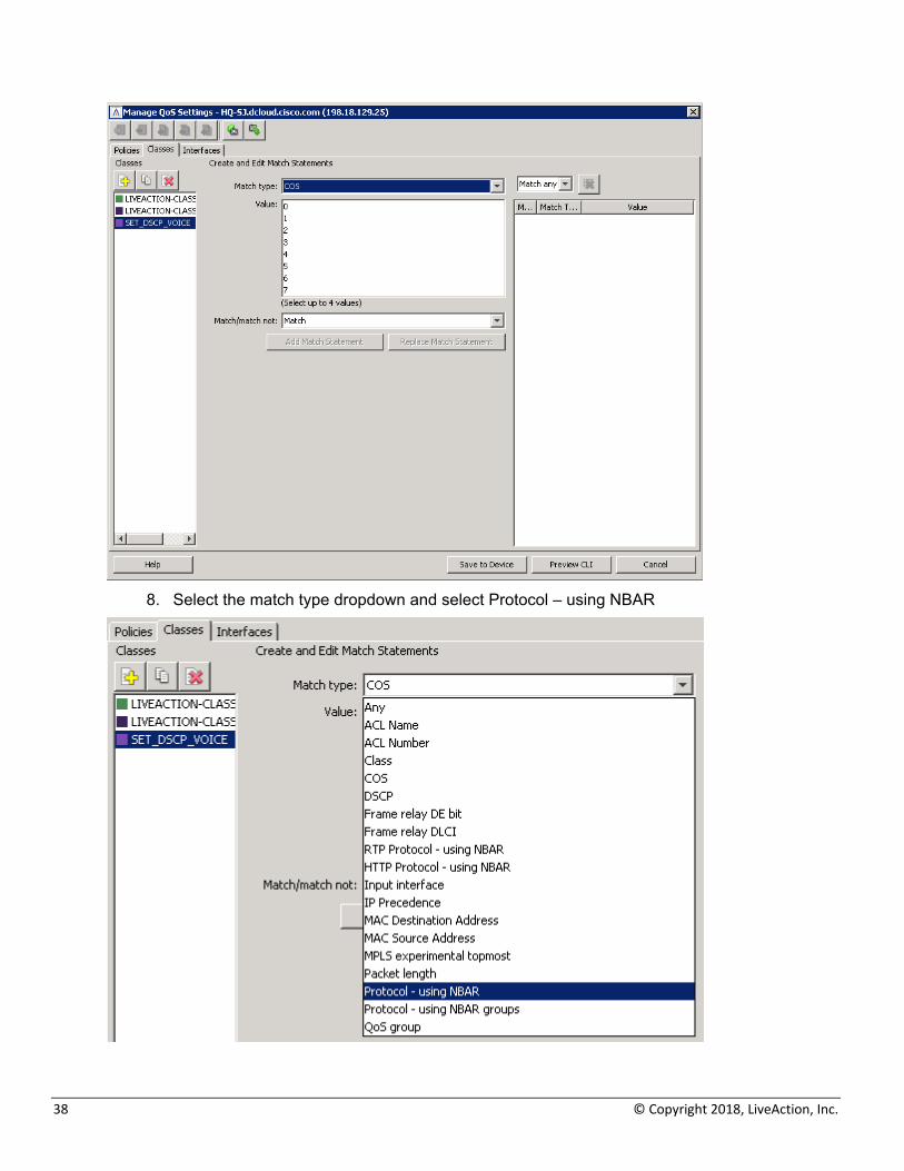
8. Select the match type dropdown and select Protocol – using NBAR
LiveAction Lab Workbook
39
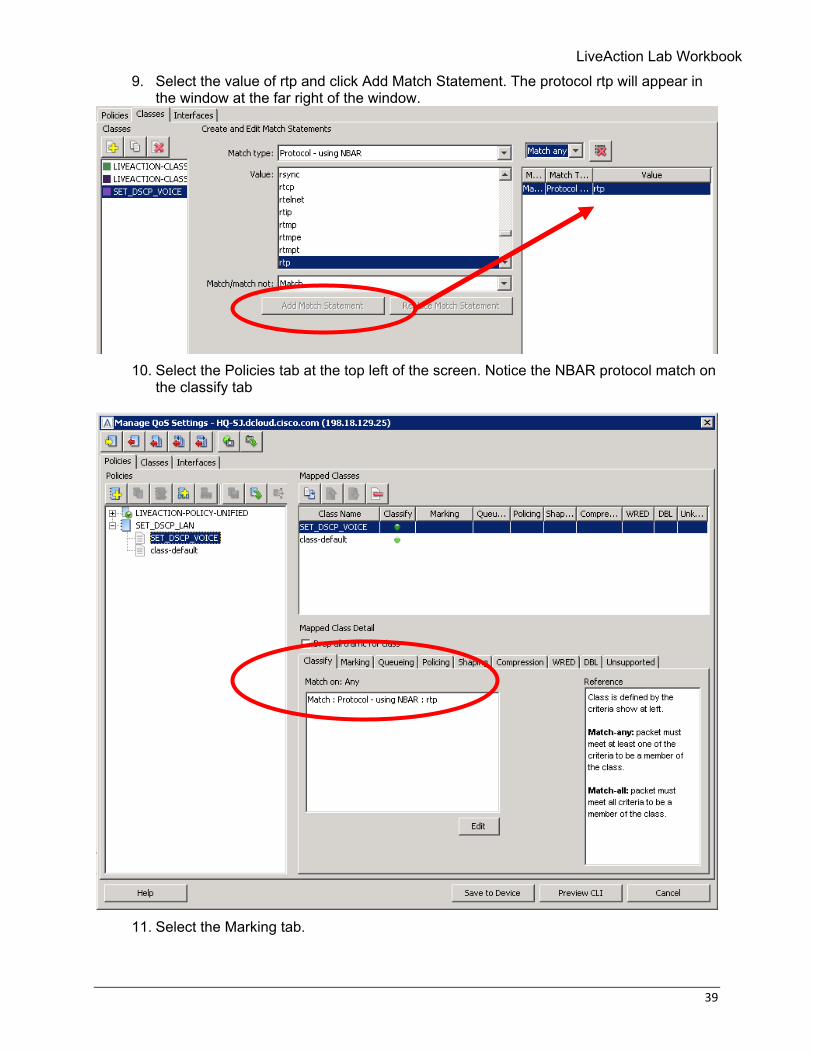
9. Select the value of rtp and click Add Match Statement. The protocol rtp will appear in the window at the far right of the window.
10. Select the Policies tab at the top left of the screen. Notice the NBAR protocol match on
the classify tab
11. Select the Marking tab.
40 © Copyright 2018, LiveAction, Inc.
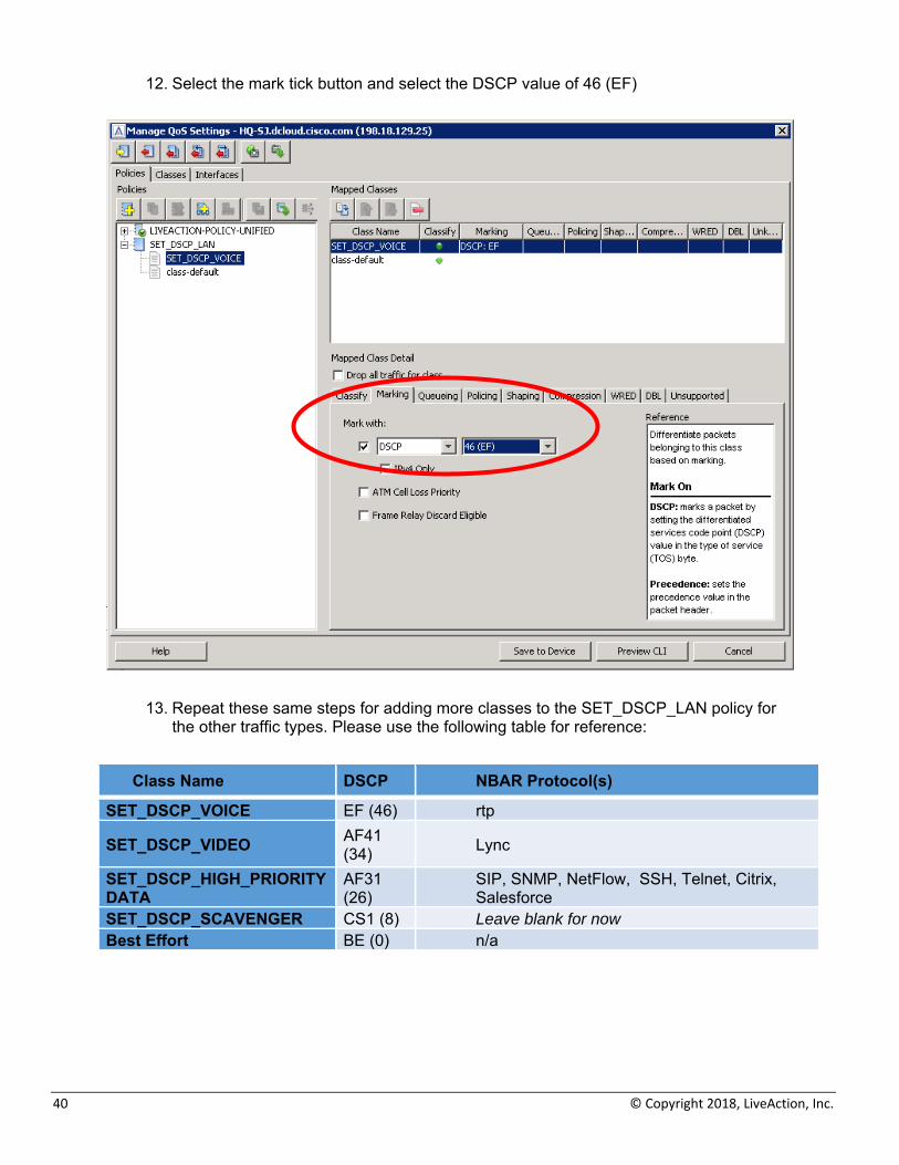
12. Select the mark tick button and select the DSCP value of 46 (EF)
13. Repeat these same steps for adding more classes to the SET_DSCP_LAN policy for the other traffic types. Please use the following table for reference:
Class Name DSCP NBAR Protocol(s)
SET_DSCP_VOICE EF (46) rtp
SET_DSCP_VIDEO AF41 (34) Lync
SET_DSCP_HIGH_PRIORITY DATA
AF31 (26)
SIP, SNMP, NetFlow, SSH, Telnet, Citrix, Salesforce
SET_DSCP_SCAVENGER CS1 (8) Leave blank for now Best Effort BE (0) n/a
LiveAction Lab Workbook
41
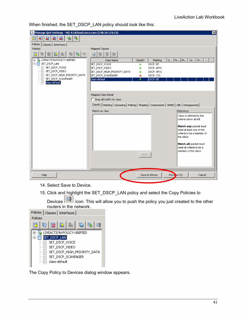
When finished, the SET_DSCP_LAN policy should look like this:
14. Select Save to Device. 15. Click and highlight the SET_DSCP_LAN policy and select the Copy Policies to
Devices icon. This will allow you to push the policy you just created to the other routers in the network.
The Copy Policy to Devices dialog window appears.
42 © Copyright 2018, LiveAction, Inc.
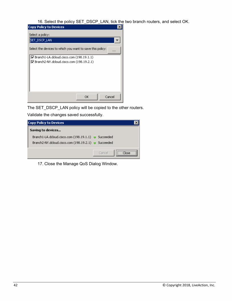
16. Select the policy SET_DSCP_LAN, tick the two branch routers, and select OK.
The SET_DSCP_LAN policy will be copied to the other routers. Validate the changes saved successfully.
17. Close the Manage QoS Dialog Window.
LiveAction Lab Workbook
43
Lab 2.5: Apply Marking Policies to Interface(s) Lab Steps:
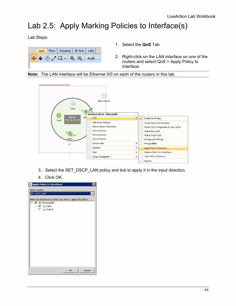
1. Select the QoS Tab
2. Right-click on the LAN interface on one of the routers and select QoS > Apply Policy to Interface.
Note: The LAN interface will be Ethernet 0/0 on each of the routers in this lab.
3. Select the SET_DSCP_LAN policy and tick to apply it in the input direction. 4. Click OK.
44 © Copyright 2018, LiveAction, Inc.
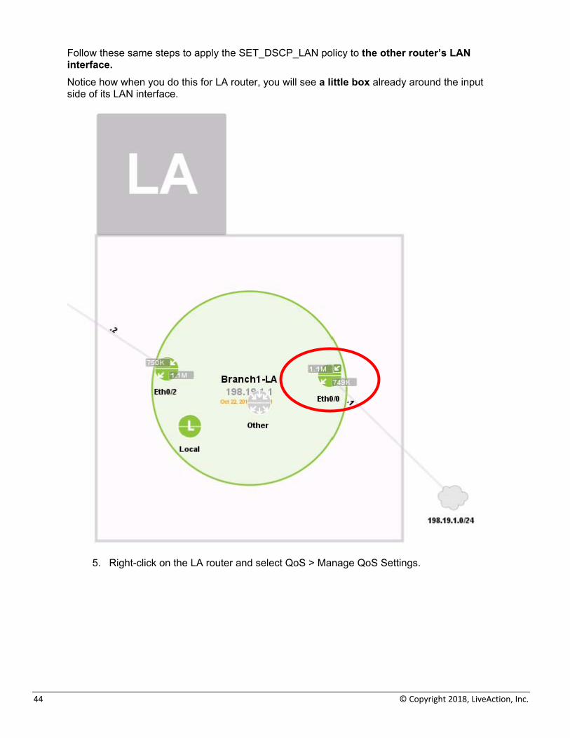
Follow these same steps to apply the SET_DSCP_LAN policy to the other router’s LAN interface. Notice how when you do this for LA router, you will see a little box already around the input side of its LAN interface.
5. Right-click on the LA router and select QoS > Manage QoS Settings.
LiveAction Lab Workbook
45
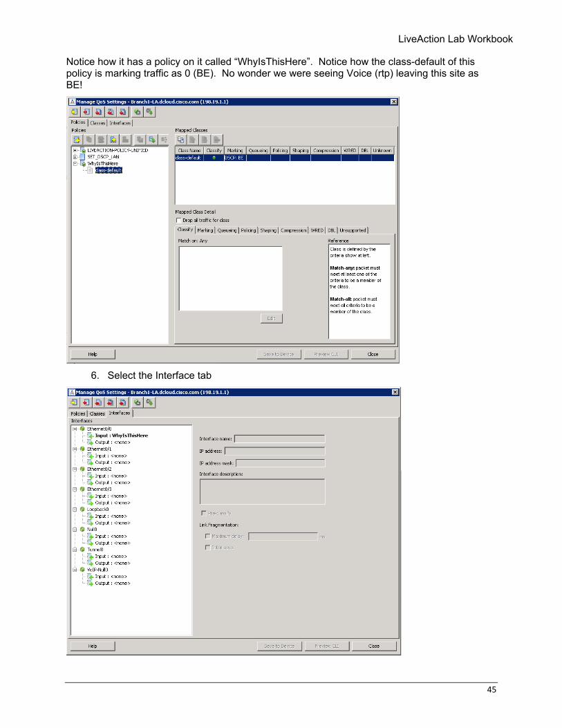
Notice how it has a policy on it called “WhyIsThisHere”. Notice how the class-default of this policy is marking traffic as 0 (BE). No wonder we were seeing Voice (rtp) leaving this site as BE!
6. Select the Interface tab
46 © Copyright 2018, LiveAction, Inc.
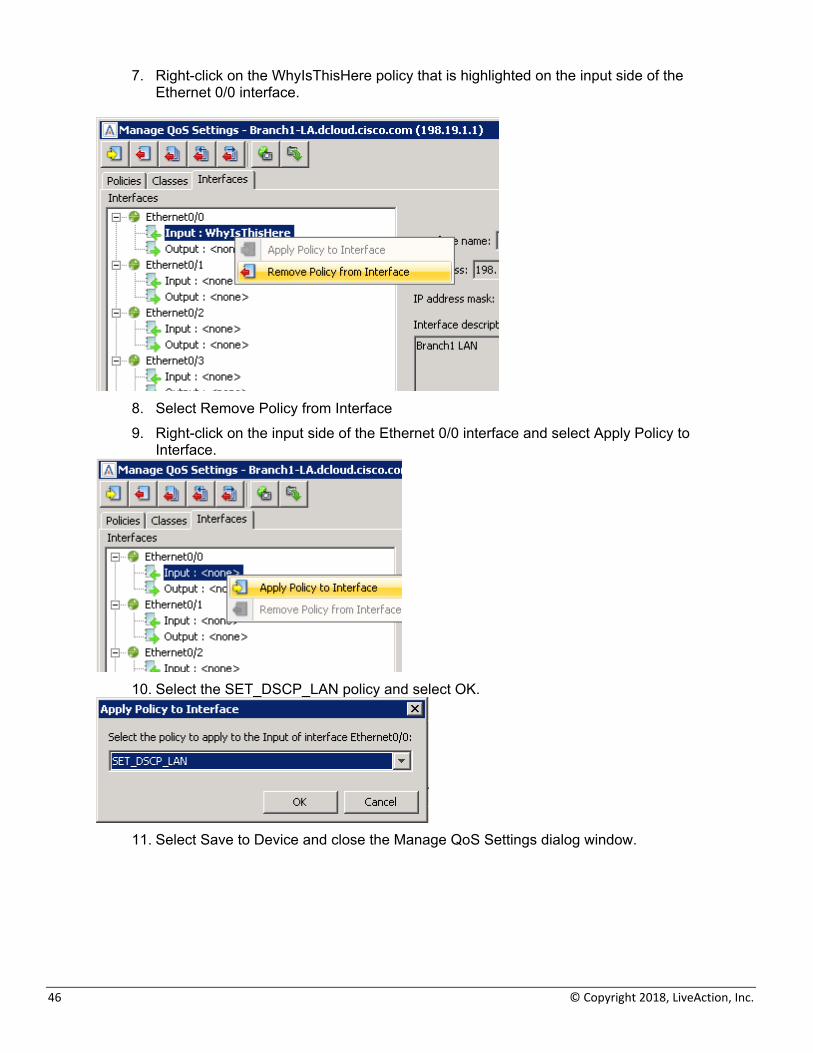
7. Right-click on the WhyIsThisHere policy that is highlighted on the input side of the Ethernet 0/0 interface.
8. Select Remove Policy from Interface 9. Right-click on the input side of the Ethernet 0/0 interface and select Apply Policy to
Interface.
10. Select the SET_DSCP_LAN policy and select OK.
11. Select Save to Device and close the Manage QoS Settings dialog window.
LiveAction Lab Workbook
47
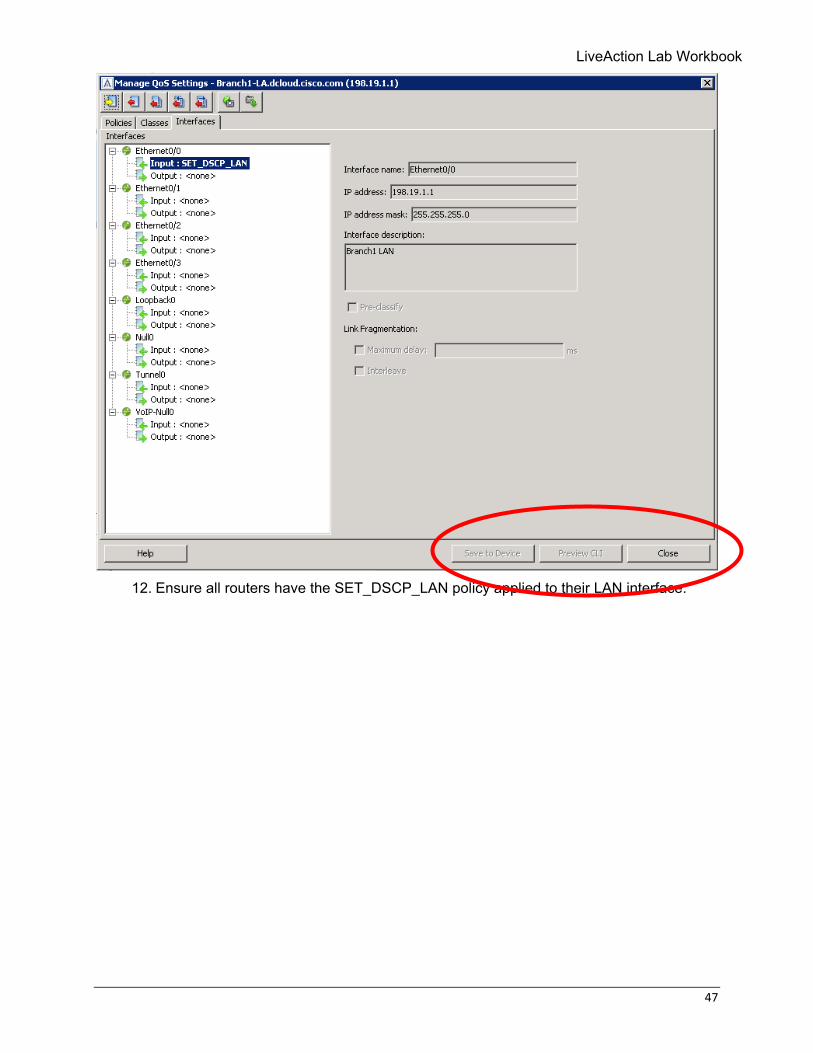
12. Ensure all routers have the SET_DSCP_LAN policy applied to their LAN interface.
48 © Copyright 2018, LiveAction, Inc.
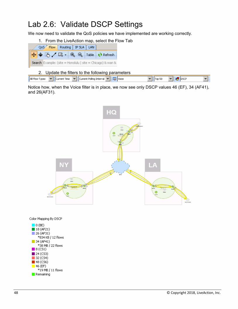
Lab 2.6: Validate DSCP Settings We now need to validate the QoS policies we have implemented are working correctly.
1. From the LiveAction map, select the Flow Tab
2. Update the filters to the following parameters
Notice how, when the Voice filter is in place, we now see only DSCP values 46 (EF), 34 (AF41), and 26(AF31).
LiveAction Lab Workbook
49
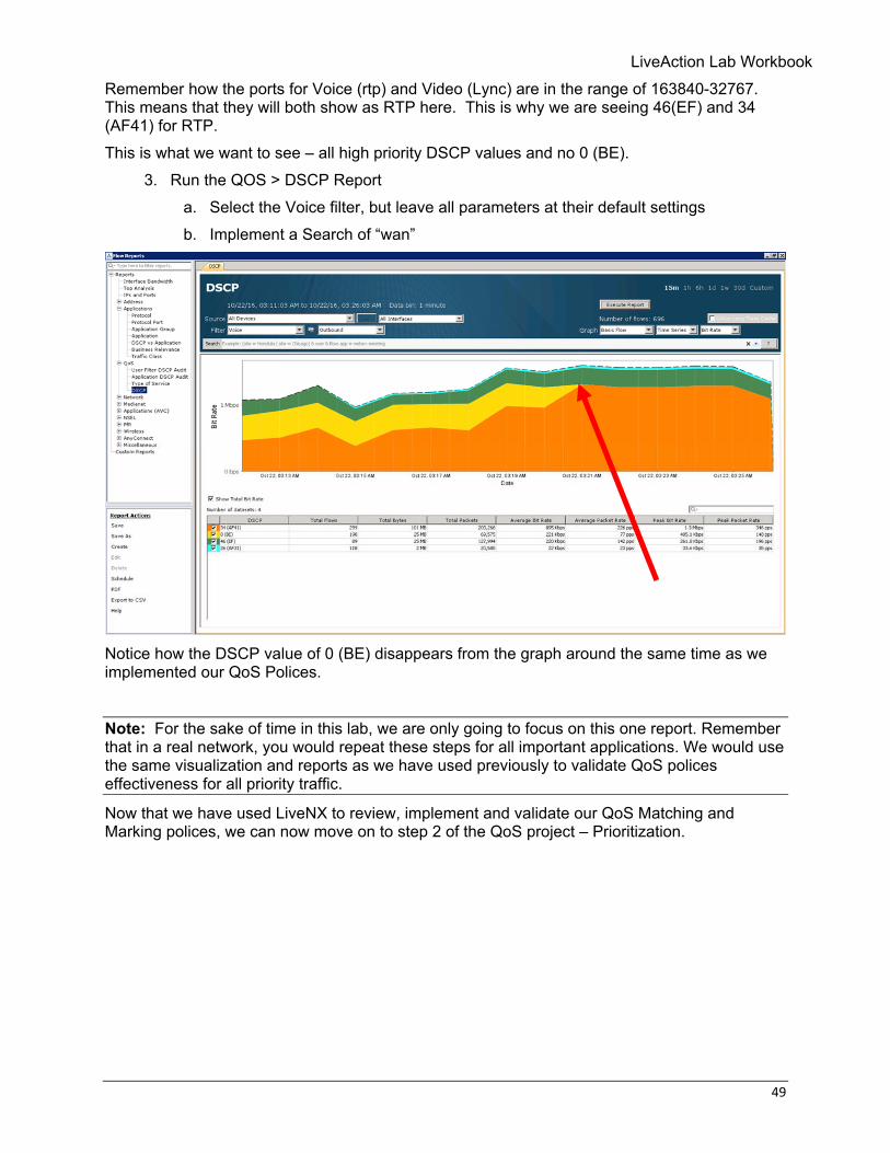
Remember how the ports for Voice (rtp) and Video (Lync) are in the range of 163840-32767. This means that they will both show as RTP here. This is why we are seeing 46(EF) and 34 (AF41) for RTP. This is what we want to see – all high priority DSCP values and no 0 (BE).
3. Run the QOS > DSCP Report a. Select the Voice filter, but leave all parameters at their default settings b. Implement a Search of “wan”
Notice how the DSCP value of 0 (BE) disappears from the graph around the same time as we implemented our QoS Polices.
Note: For the sake of time in this lab, we are only going to focus on this one report. Remember that in a real network, you would repeat these steps for all important applications. We would use the same visualization and reports as we have used previously to validate QoS polices effectiveness for all priority traffic.
Now that we have used LiveNX to review, implement and validate our QoS Matching and Marking polices, we can now move on to step 2 of the QoS project – Prioritization.

50 © Copyright 2018, LiveAction, Inc.
Lab 3: QoS Prioritization & Queueing
LiveAction Lab Workbook
51
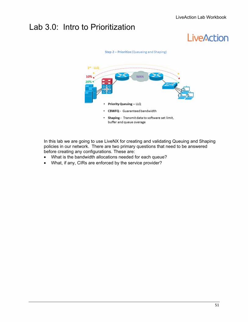
Lab 3.0: Intro to Prioritization
In this lab we are going to use LiveNX for creating and validating Queuing and Shaping policies in our network. There are two primary questions that need to be answered before creating any configurations. These are: • What is the bandwidth allocations needed for each queue? • What, if any, CIRs are enforced by the service provider?
52 © Copyright 2018, LiveAction, Inc.
Lab 3.1: Run the Reports! We will tackle the bandwidth question first. The best way to answer this question is to use LiveNX’s reporting to understand the priority application’s capacity needs. Since we have successfully created and validated Matching and Marking polices, we can now just reference the respective DSCP value’s bandwidth usage to quantify our applications requirements. Lab Steps:
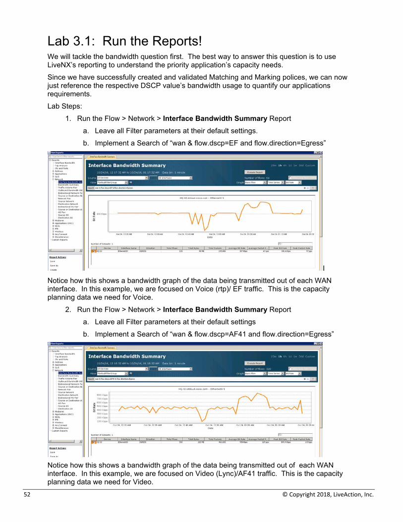
1. Run the Flow > Network > Interface Bandwidth Summary Report a. Leave all Filter parameters at their default settings. b. Implement a Search of “wan & flow.dscp=EF and flow.direction=Egress”
I Notice how this shows a bandwidth graph of the data being transmitted out of each WAN interface. In this example, we are focused on Voice (rtp)/ EF traffic. This is the capacity planning data we need for Voice.
2. Run the Flow > Network > Interface Bandwidth Summary Report a. Leave all Filter parameters at their default settings b. Implement a Search of “wan & flow.dscp=AF41 and flow.direction=Egress”
Notice how this shows a bandwidth graph of the data being transmitted out of each WAN interface. In this example, we are focused on Video (Lync)/AF41 traffic. This is the capacity planning data we need for Video.
LiveAction Lab Workbook
53
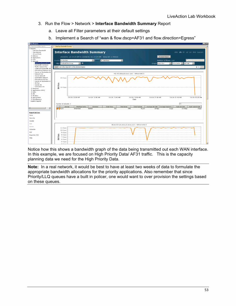
3. Run the Flow > Network > Interface Bandwidth Summary Report a. Leave all Filter parameters at their default settings b. Implement a Search of “wan & flow.dscp=AF31 and flow.direction=Egress”
Notice how this shows a bandwidth graph of the data being transmitted out each WAN interface. In this example, we are focused on High Priority Data/ AF31 traffic. This is the capacity planning data we need for the High Priority Data.
Note: In a real network, it would be best to have at least two weeks of data to formulate the appropriate bandwidth allocations for the priority applications. Also remember that since Priority/LLQ queues have a built in policer, one would want to over provision the settings based on these queues.
54 © Copyright 2018, LiveAction, Inc.
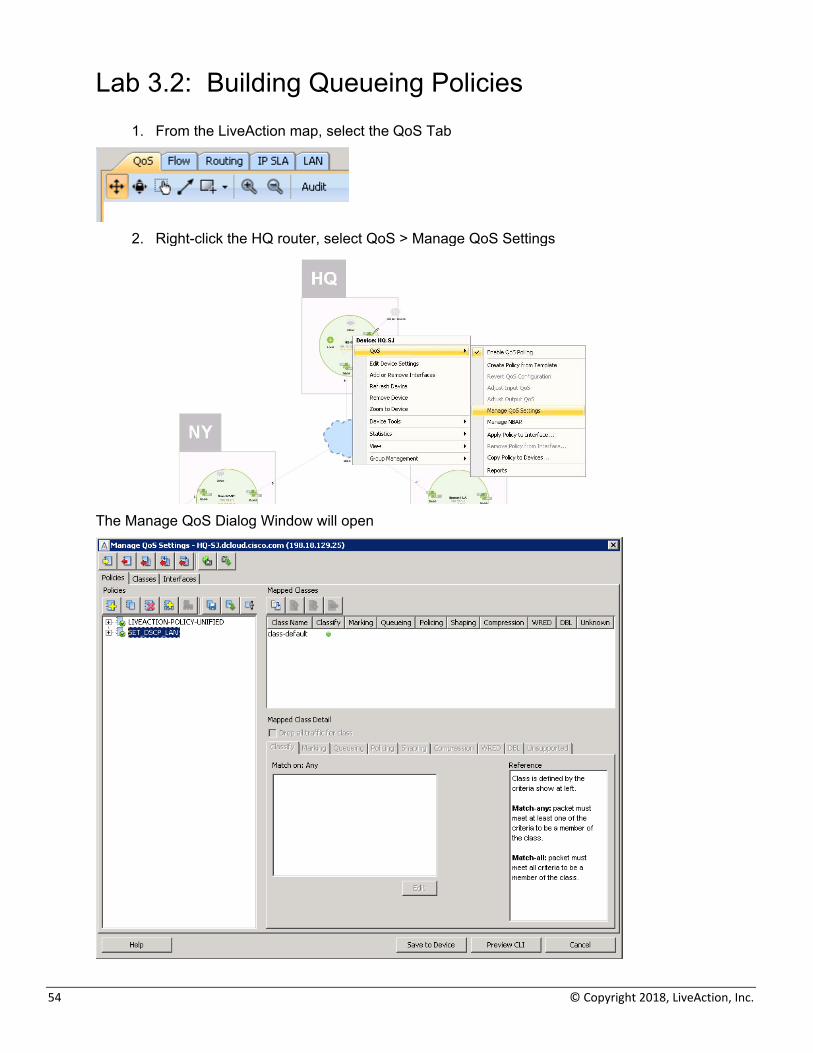
Lab 3.2: Building Queueing Policies
1. From the LiveAction map, select the QoS Tab
2. Right-click the HQ router, select QoS > Manage QoS Settings
The Manage QoS Dialog Window will open
LiveAction Lab Workbook
55
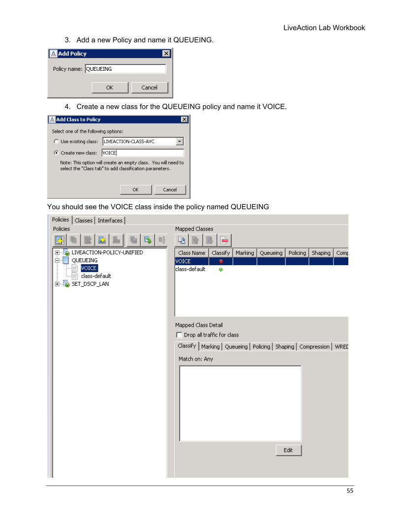
3. Add a new Policy and name it QUEUEING.
4. Create a new class for the QUEUEING policy and name it VOICE.
You should see the VOICE class inside the policy named QUEUEING
56 © Copyright 2018, LiveAction, Inc.
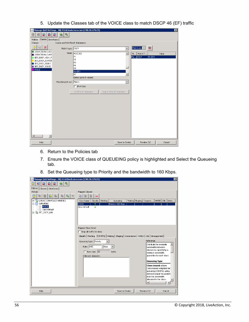
5. Update the Classes tab of the VOICE class to match DSCP 46 (EF) traffic
6. Return to the Policies tab 7. Ensure the VOICE class of QUEUEING policy is highlighted and Select the Queueing
tab. 8. Set the Queueing type to Priority and the bandwidth to 160 Kbps.
LiveAction Lab Workbook
57
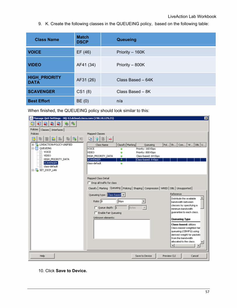
9. K. Create the following classes in the QUEUEING policy, based on the following table:
When finished, the QUEUEING policy should look similar to this:
10. Click Save to Device.
Class Name Match DSCP Queueing
VOICE EF (46) Priority – 160K
VIDEO AF41 (34) Priority – 800K
HIGH_PRIORITY DATA AF31 (26) Class Based – 64K
SCAVENGER CS1 (8) Class Based – 8K
Best Effort BE (0) n/a
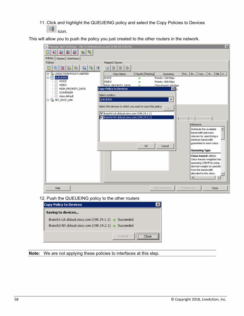
58 © Copyright 2018, LiveAction, Inc.
11. Click and highlight the QUEUEING policy and select the Copy Policies to Devices
icon. This will allow you to push the policy you just created to the other routers in the network.
12. Push the QUEUEING policy to the other routers
Note: We are not applying these policies to interfaces at this step.

LiveAction Lab Workbook
59
Lab 4: Shaping / Scaling
60 © Copyright 2018, LiveAction, Inc.
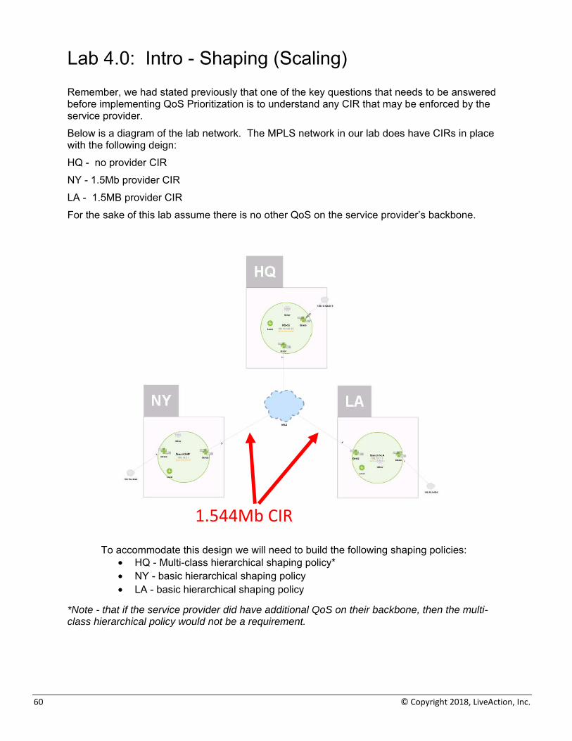
Lab 4.0: Intro - Shaping (Scaling) Remember, we had stated previously that one of the key questions that needs to be answered before implementing QoS Prioritization is to understand any CIR that may be enforced by the service provider. Below is a diagram of the lab network. The MPLS network in our lab does have CIRs in place with the following deign: HQ - no provider CIR NY - 1.5Mb provider CIR LA - 1.5MB provider CIR For the sake of this lab assume there is no other QoS on the service provider’s backbone.
To accommodate this design we will need to build the following shaping policies:
• HQ - Multi-class hierarchical shaping policy* • NY - basic hierarchical shaping policy • LA - basic hierarchical shaping policy
*Note - that if the service provider did have additional QoS on their backbone, then the multi-class hierarchical policy would not be a requirement.
1.544Mb CIR
LiveAction Lab Workbook
61
Lab 4.1: Shaping (Scaling)
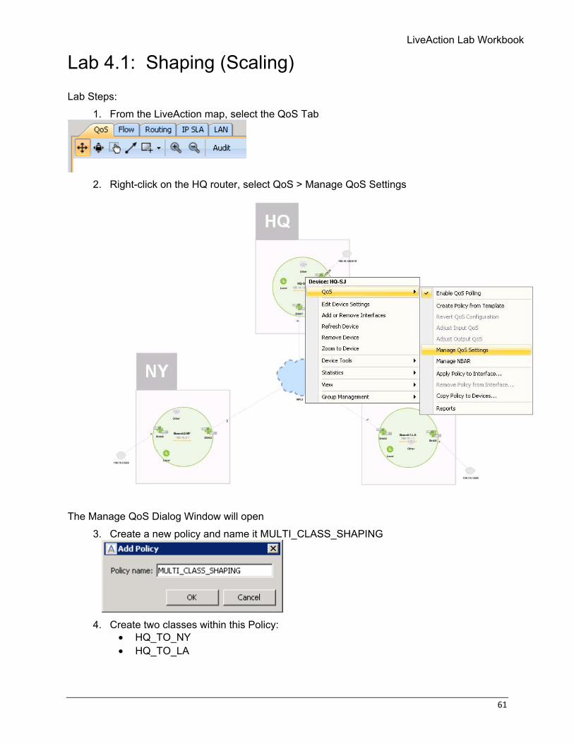
Lab Steps: 1. From the LiveAction map, select the QoS Tab
2. Right-click on the HQ router, select QoS > Manage QoS Settings
The Manage QoS Dialog Window will open
3. Create a new policy and name it MULTI_CLASS_SHAPING
4. Create two classes within this Policy:
• HQ_TO_NY • HQ_TO_LA
62 © Copyright 2018, LiveAction, Inc.
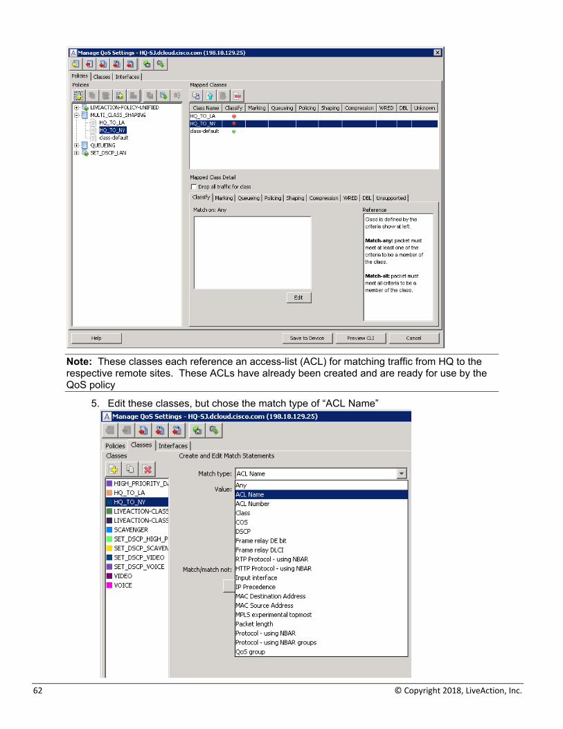
Note: These classes each reference an access-list (ACL) for matching traffic from HQ to the respective remote sites. These ACLs have already been created and are ready for use by the QoS policy
5. Edit these classes, but chose the match type of “ACL Name”
LiveAction Lab Workbook
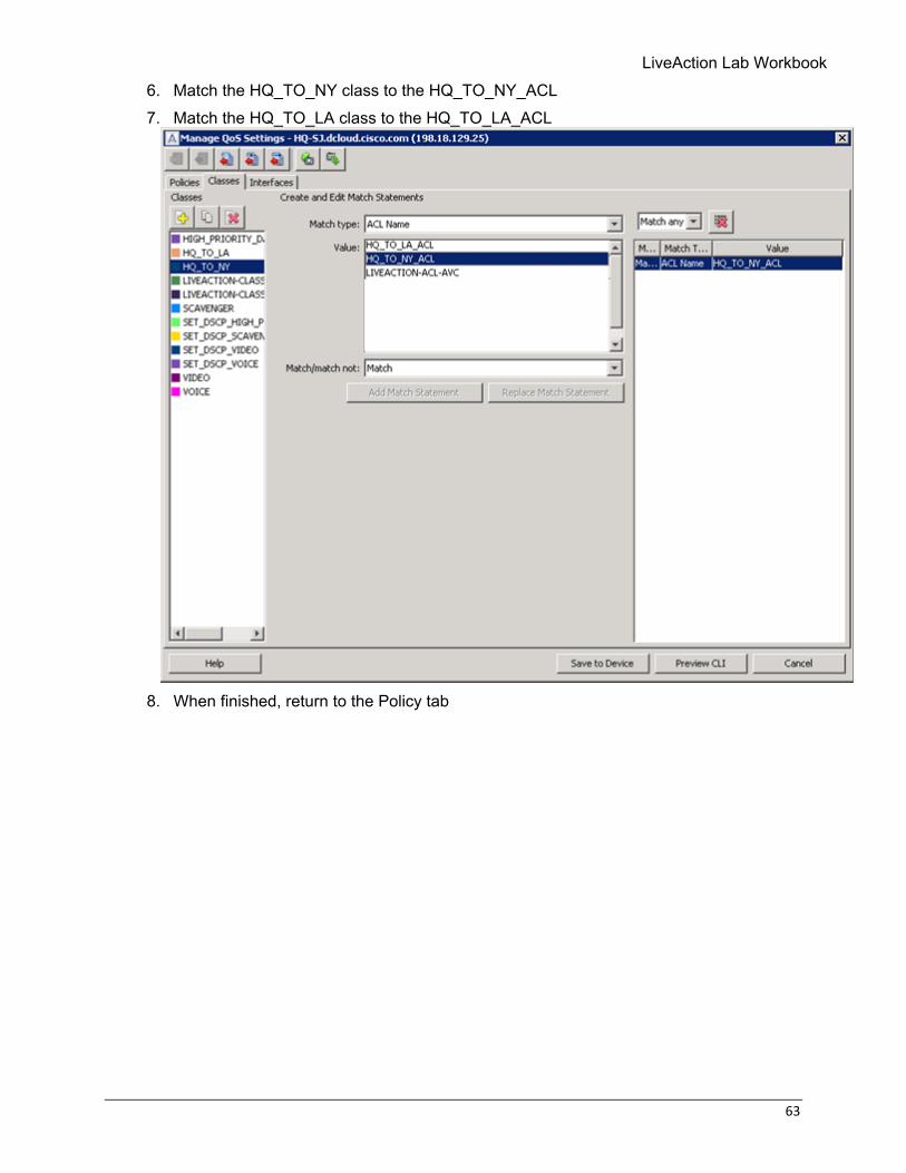
63
6. Match the HQ_TO_NY class to the HQ_TO_NY_ACL 7. Match the HQ_TO_LA class to the HQ_TO_LA_ACL
8. When finished, return to the Policy tab
64 © Copyright 2018, LiveAction, Inc.
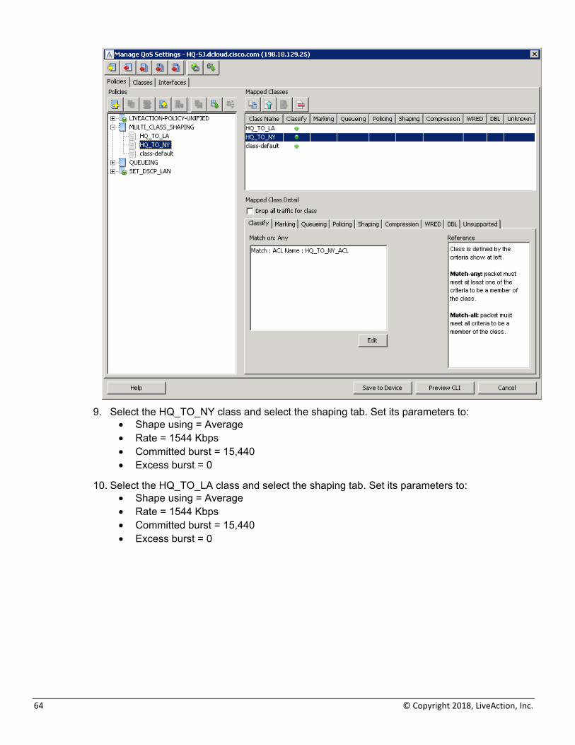
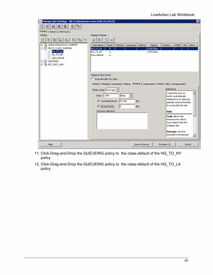
9. Select the HQ_TO_NY class and select the shaping tab. Set its parameters to:
• Shape using = Average • Rate = 1544 Kbps • Committed burst = 15,440 • Excess burst = 0
10. Select the HQ_TO_LA class and select the shaping tab. Set its parameters to: • Shape using = Average • Rate = 1544 Kbps • Committed burst = 15,440 • Excess burst = 0
LiveAction Lab Workbook
65
11. Click-Drag-and-Drop the QUEUEING policy to the class-default of the HQ_TO_NY
policy 12. Click-Drag-and-Drop the QUEUEING policy to the class-default of the HQ_TO_LA
policy
66 © Copyright 2018, LiveAction, Inc.
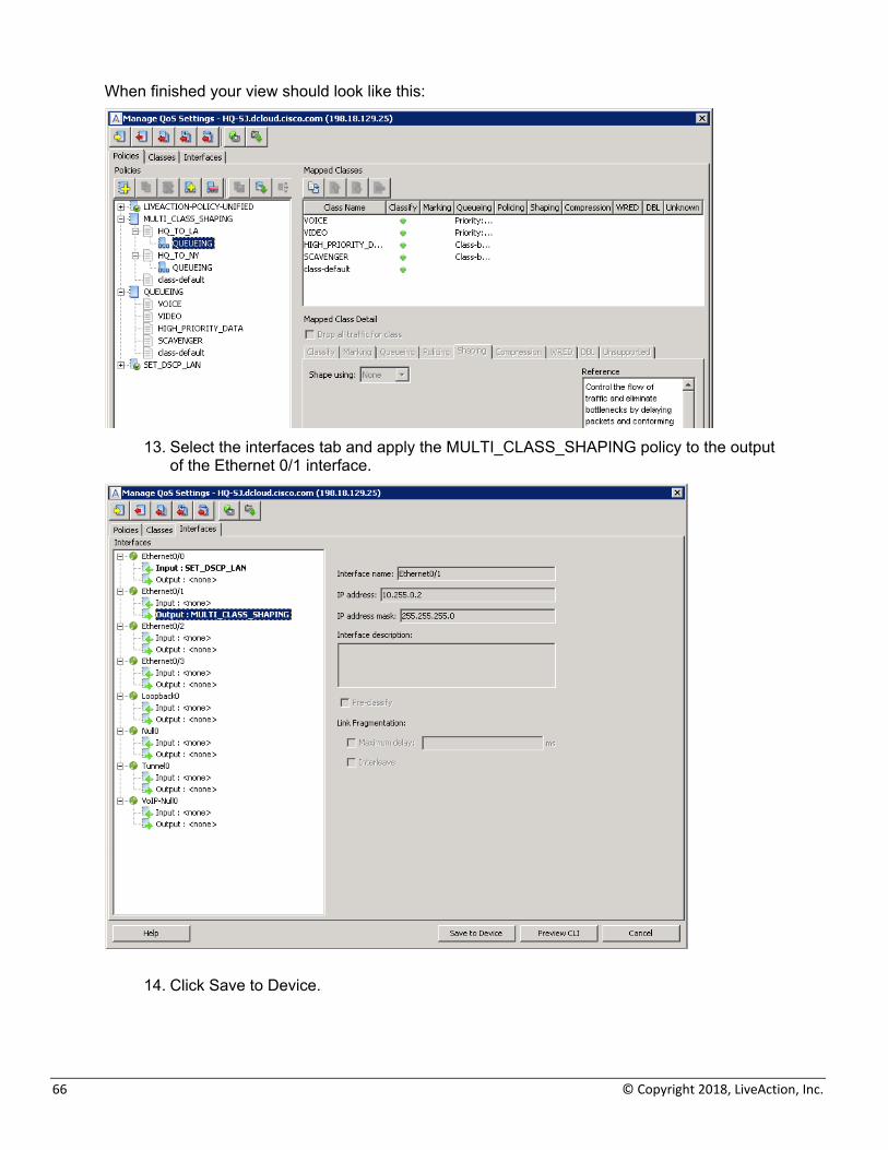
When finished your view should look like this:
13. Select the interfaces tab and apply the MULTI_CLASS_SHAPING policy to the output
of the Ethernet 0/1 interface.
14. Click Save to Device.
LiveAction Lab Workbook
67
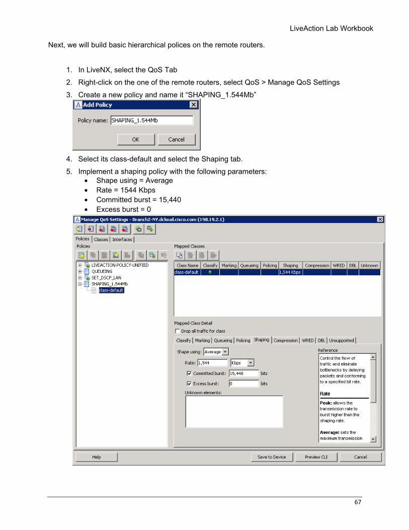
Next, we will build basic hierarchical polices on the remote routers.
1. In LiveNX, select the QoS Tab 2. Right-click on the one of the remote routers, select QoS > Manage QoS Settings 3. Create a new policy and name it “SHAPING_1.544Mb”
4. Select its class-default and select the Shaping tab. 5. Implement a shaping policy with the following parameters:
• Shape using = Average • Rate = 1544 Kbps • Committed burst = 15,440 • Excess burst = 0
68 © Copyright 2018, LiveAction, Inc.
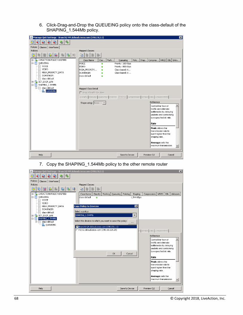
6. Click-Drag-and-Drop the QUEUEING policy onto the class-default of the SHAPING_1.544Mb policy.
7. Copy the SHAPING_1.544Mb policy to the other remote router
LiveAction Lab Workbook
69
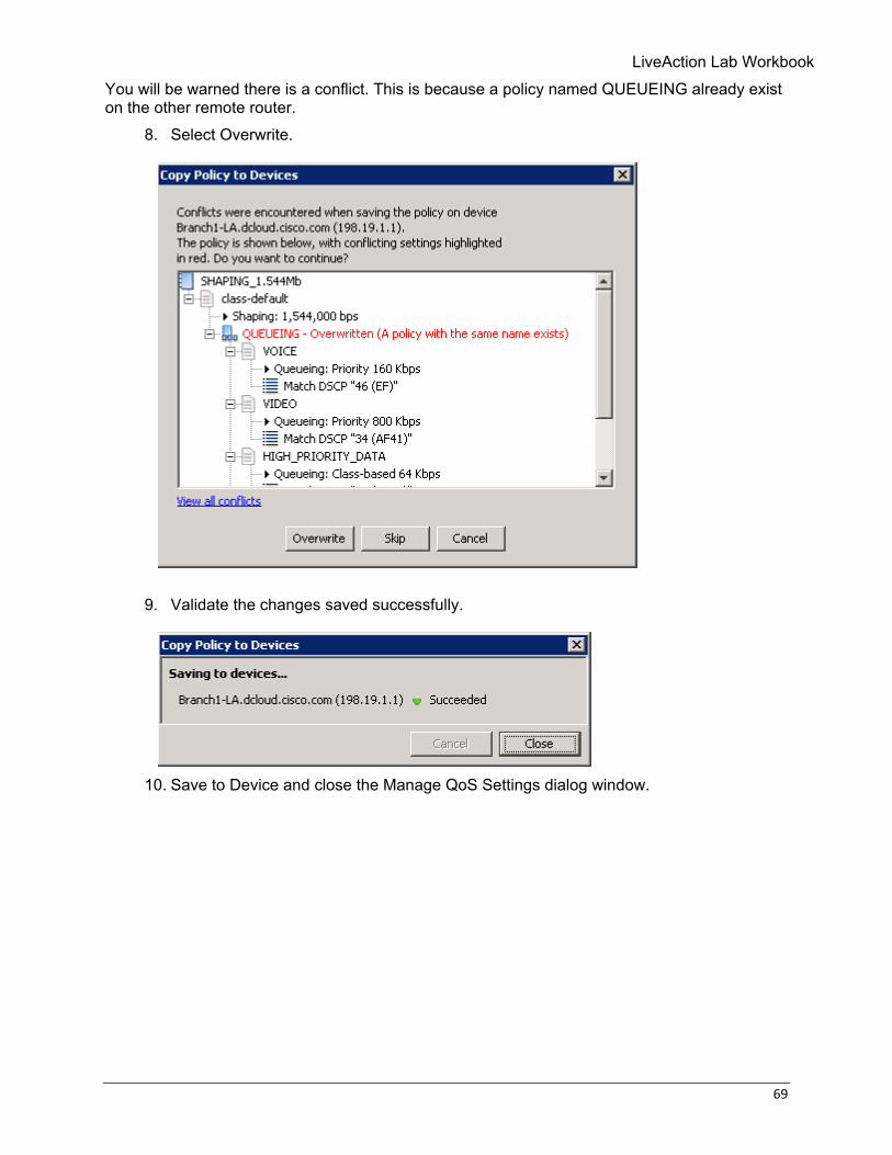
You will be warned there is a conflict. This is because a policy named QUEUEING already exist on the other remote router.
8. Select Overwrite.
9. Validate the changes saved successfully.
10. Save to Device and close the Manage QoS Settings dialog window.
70 © Copyright 2018, LiveAction, Inc.
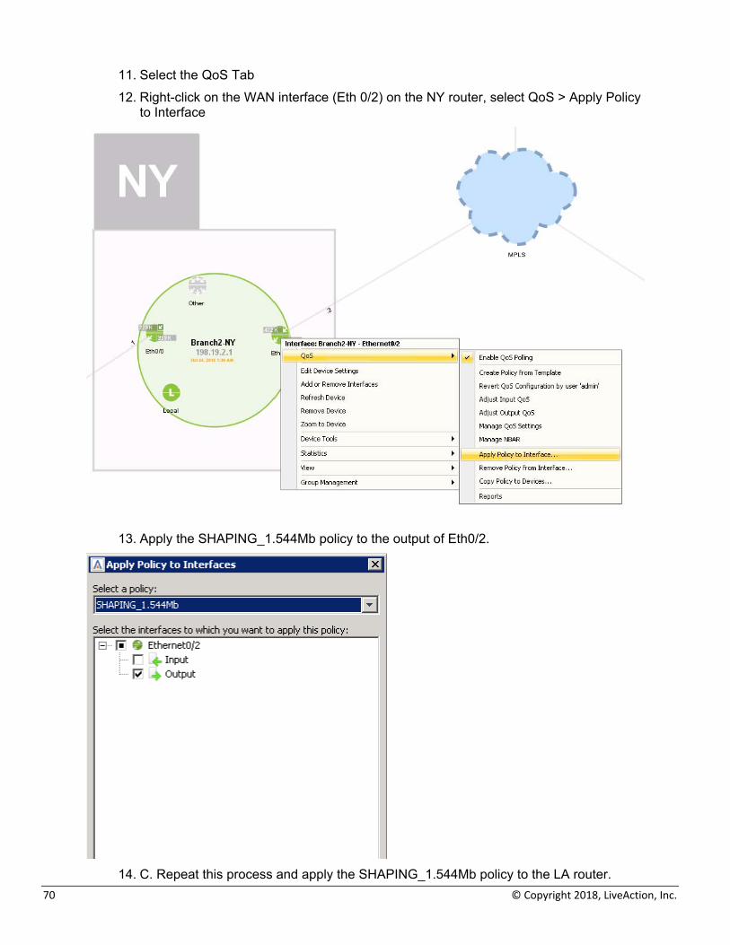
11. Select the QoS Tab 12. Right-click on the WAN interface (Eth 0/2) on the NY router, select QoS > Apply Policy
to Interface
13. Apply the SHAPING_1.544Mb policy to the output of Eth0/2.
14. C. Repeat this process and apply the SHAPING_1.544Mb policy to the LA router.
LiveAction Lab Workbook
71
Lab 5: Throttling Traffic
72 © Copyright 2018, LiveAction, Inc.
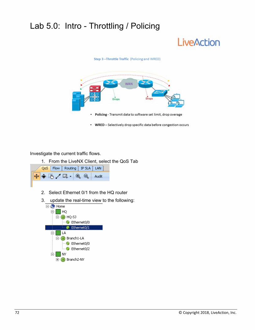
Lab 5.0: Intro - Throttling / Policing
Investigate the current traffic flows.
1. From the LiveNX Client, select the QoS Tab
2. Select Ethernet 0/1 from the HQ router 3. update the real-time view to the following:
LiveAction Lab Workbook
73
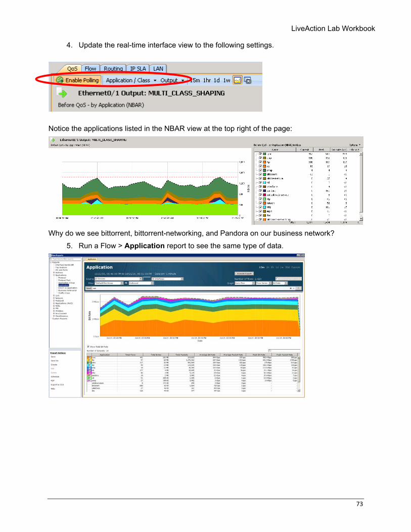
4. Update the real-time interface view to the following settings.
Notice the applications listed in the NBAR view at the top right of the page:
Why do we see bittorrent, bittorrent-networking, and Pandora on our business network?
5. Run a Flow > Application report to see the same type of data.
74 © Copyright 2018, LiveAction, Inc.
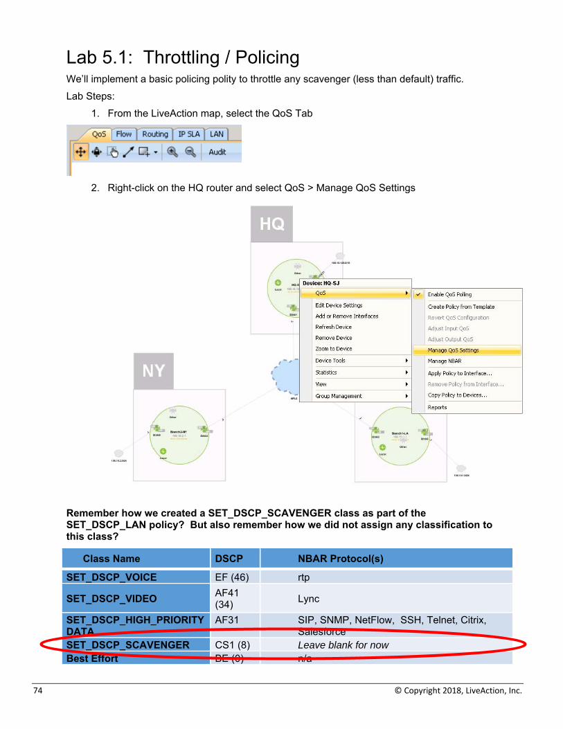
Lab 5.1: Throttling / Policing We’ll implement a basic policing polity to throttle any scavenger (less than default) traffic. Lab Steps:
1. From the LiveAction map, select the QoS Tab
2. Right-click on the HQ router and select QoS > Manage QoS Settings
Remember how we created a SET_DSCP_SCAVENGER class as part of the SET_DSCP_LAN policy? But also remember how we did not assign any classification to this class?
Class Name DSCP NBAR Protocol(s)
SET_DSCP_VOICE EF (46) rtp
SET_DSCP_VIDEO AF41 (34) Lync
SET_DSCP_HIGH_PRIORITY DATA
AF31 SIP, SNMP, NetFlow, SSH, Telnet, Citrix, Salesforce
SET_DSCP_SCAVENGER CS1 (8) Leave blank for now Best Effort BE (0) n/a
LiveAction Lab Workbook
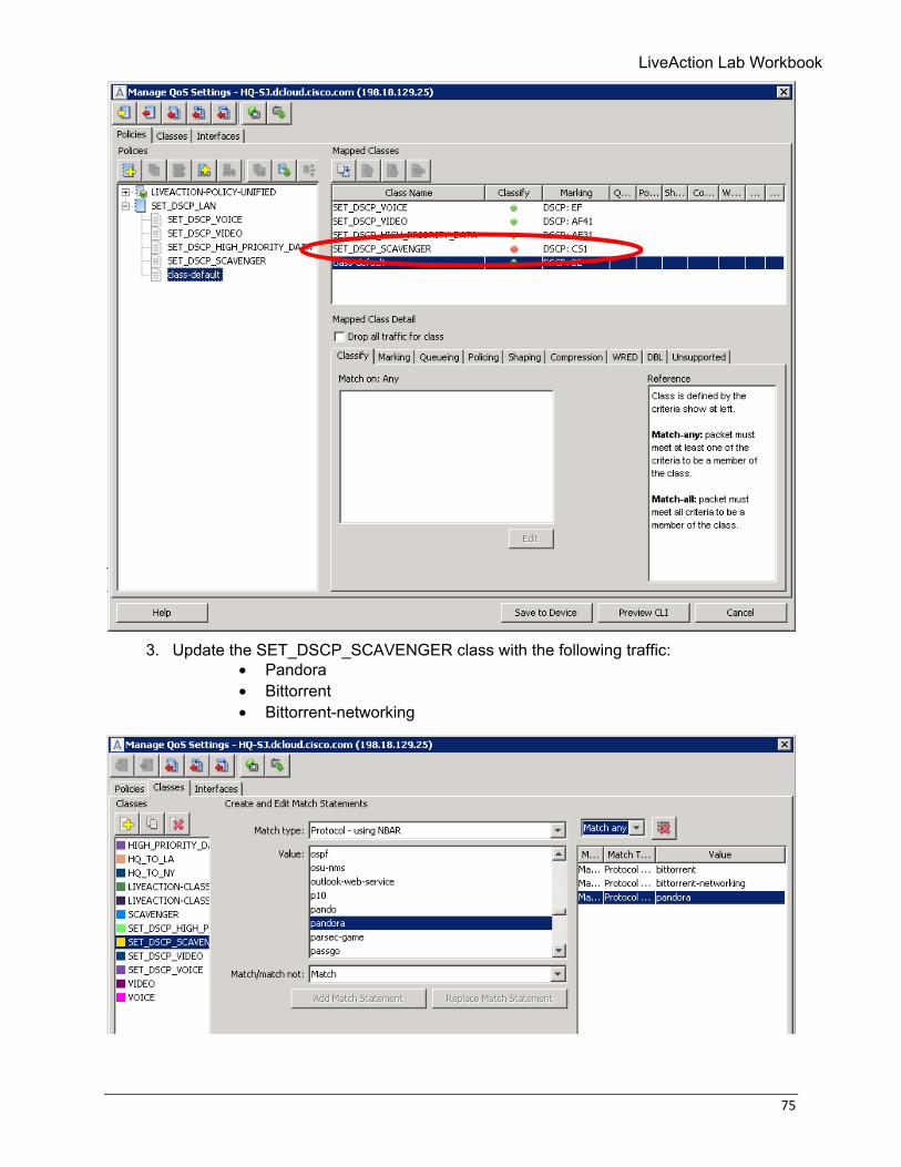
75
3. Update the SET_DSCP_SCAVENGER class with the following traffic:
• Pandora • Bittorrent • Bittorrent-networking
76 © Copyright 2018, LiveAction, Inc.
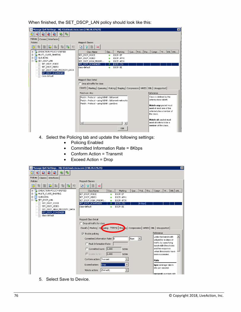
When finished, the SET_DSCP_LAN policy should look like this:
4. Select the Policing tab and update the following settings:
• Policing Enabled • Committed Information Rate = 8Kbps • Conform Action = Transmit • Exceed Action = Drop
5. Select Save to Device.
LiveAction Lab Workbook
77
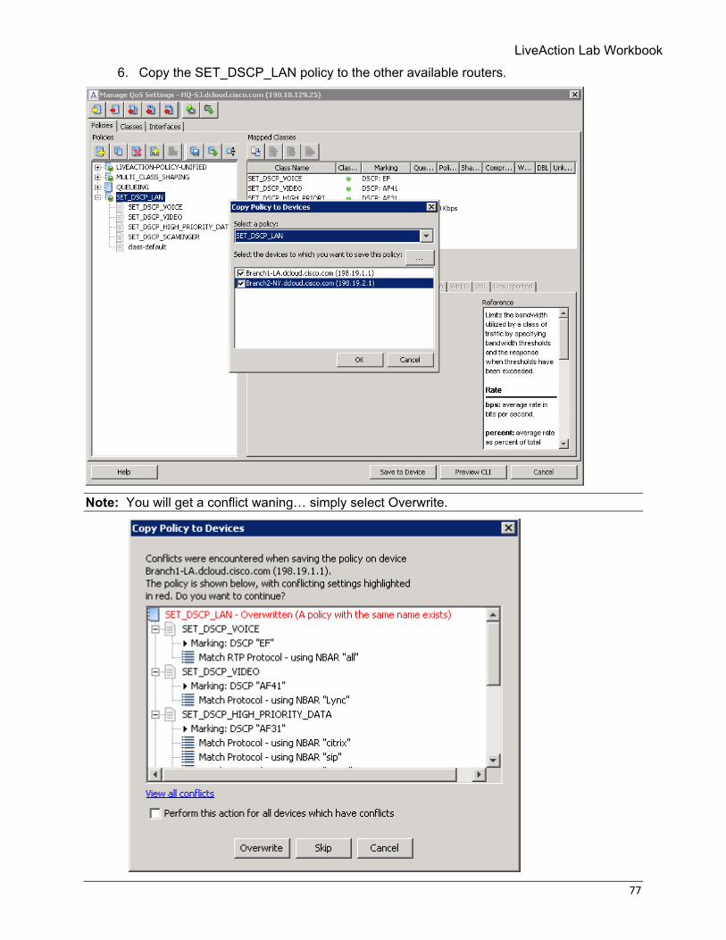
6. Copy the SET_DSCP_LAN policy to the other available routers.
Note: You will get a conflict waning… simply select Overwrite.
78 © Copyright 2018, LiveAction, Inc.
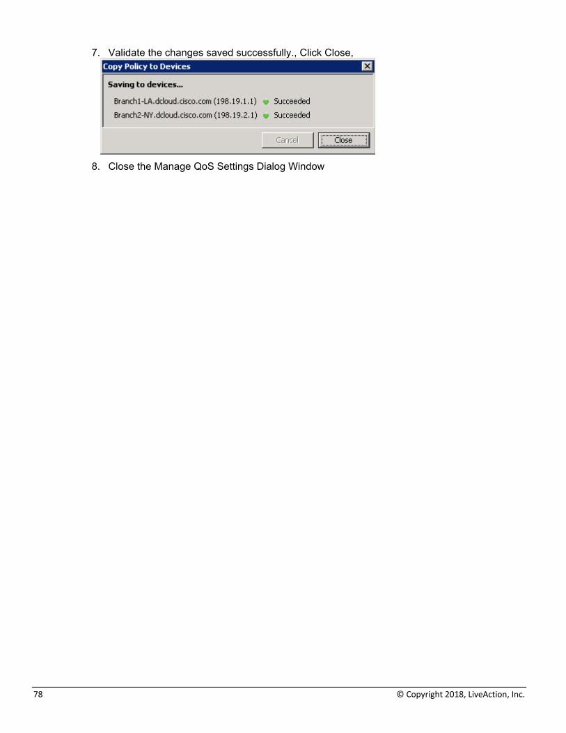
7. Validate the changes saved successfully., Click Close,
8. Close the Manage QoS Settings Dialog Window
LiveAction Lab Workbook
79
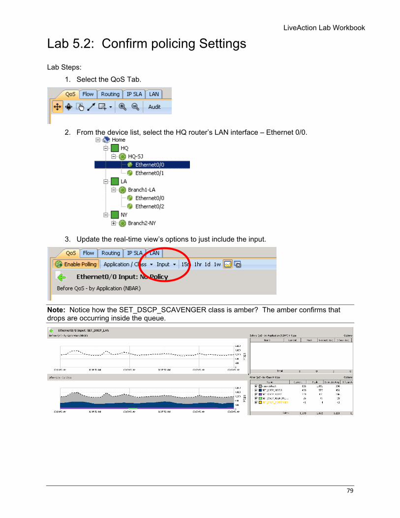
Lab 5.2: Confirm policing Settings
Lab Steps: 1. Select the QoS Tab.
2. From the device list, select the HQ router’s LAN interface – Ethernet 0/0.
3. Update the real-time view’s options to just include the input.
Note: Notice how the SET_DSCP_SCAVENGER class is amber? The amber confirms that drops are occurring inside the queue.

80 © Copyright 2018, LiveAction, Inc.
Lab 6: Buffer tuning
LiveAction Lab Workbook
81
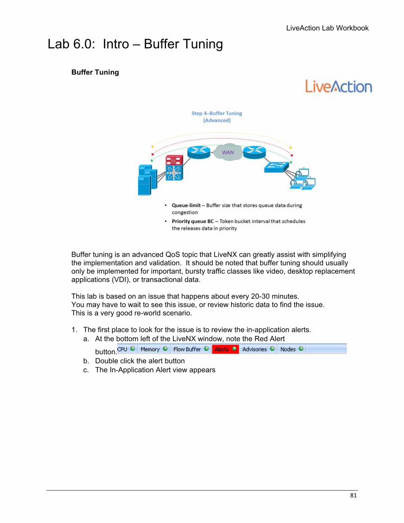
Lab 6.0: Intro – Buffer Tuning Buffer Tuning
Buffer tuning is an advanced QoS topic that LiveNX can greatly assist with simplifying the implementation and validation. It should be noted that buffer tuning should usually only be implemented for important, bursty traffic classes like video, desktop replacement applications (VDI), or transactional data. This lab is based on an issue that happens about every 20-30 minutes. You may have to wait to see this issue, or review historic data to find the issue. This is a very good re-world scenario. 1. The first place to look for the issue is to review the in-application alerts.
a. At the bottom left of the LiveNX window, note the Red Alert
button. b. Double click the alert button c. The In-Application Alert view appears
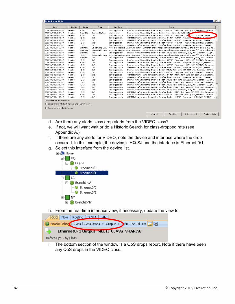
82 © Copyright 2018, LiveAction, Inc.
d. Are there any alerts class drop alerts from the VIDEO class? e. If not, we will want wait or do a Historic Search for class-dropped rate (see
Appendix A.) f. If there are any alerts for VIDEO, note the device and interface where the drop
occurred. In this example, the device is HQ-SJ and the interface is Ethernet 0/1. g. Select this interface from the device list.
h. From the real-time interface view, if necessary, update the view to:
i. The bottom section of the window is a QoS drops report. Note if there have been
any QoS drops in the VIDEO class.
LiveAction Lab Workbook
83
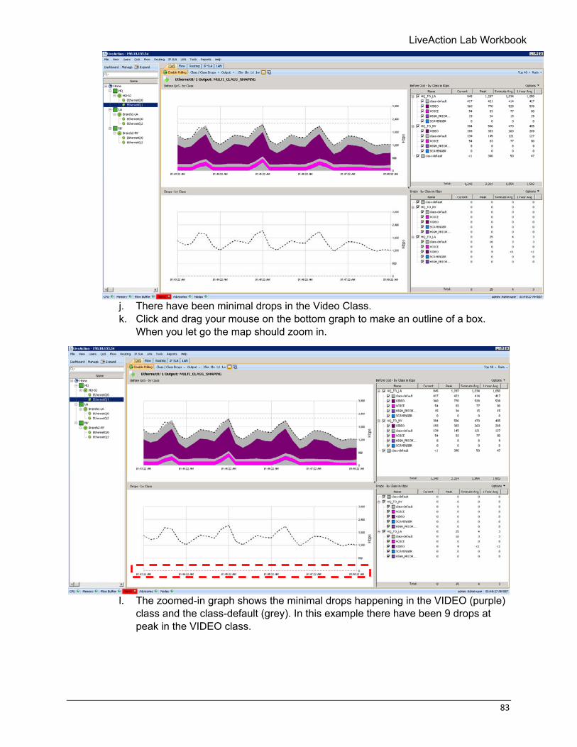
j. There have been minimal drops in the Video Class. k. Click and drag your mouse on the bottom graph to make an outline of a box.
When you let go the map should zoom in.
l. The zoomed-in graph shows the minimal drops happening in the VIDEO (purple)
class and the class-default (grey). In this example there have been 9 drops at peak in the VIDEO class.
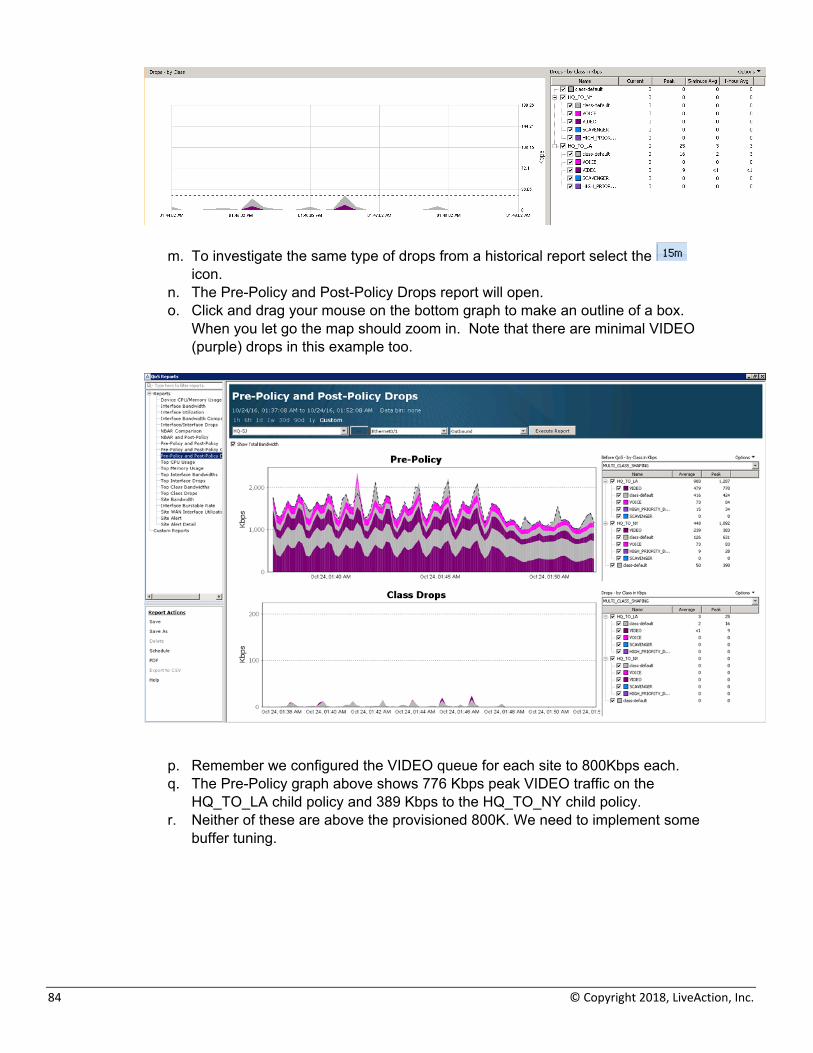
84 © Copyright 2018, LiveAction, Inc.
m. To investigate the same type of drops from a historical report select the icon.
n. The Pre-Policy and Post-Policy Drops report will open. o. Click and drag your mouse on the bottom graph to make an outline of a box.
When you let go the map should zoom in. Note that there are minimal VIDEO (purple) drops in this example too.
p. Remember we configured the VIDEO queue for each site to 800Kbps each. q. The Pre-Policy graph above shows 776 Kbps peak VIDEO traffic on the
HQ_TO_LA child policy and 389 Kbps to the HQ_TO_NY child policy. r. Neither of these are above the provisioned 800K. We need to implement some
buffer tuning.
LiveAction Lab Workbook
85
Lab 6.1: Implementing Tuning
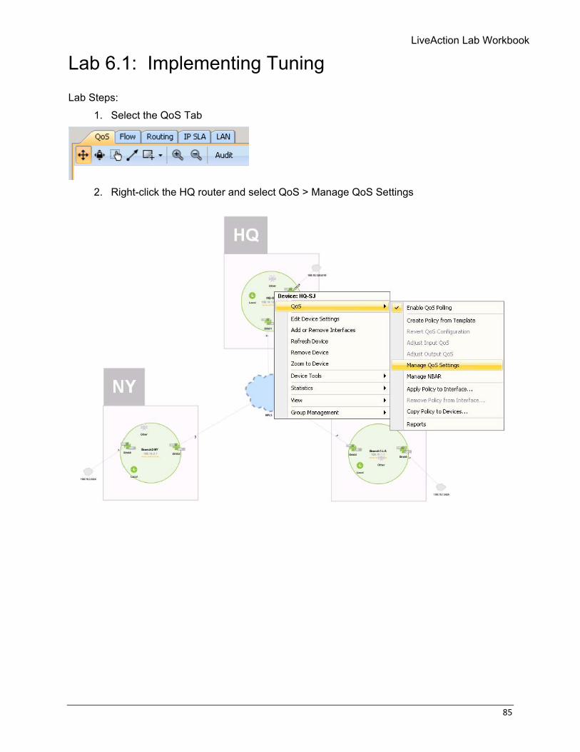
Lab Steps: 1. Select the QoS Tab
2. Right-click the HQ router and select QoS > Manage QoS Settings
86 © Copyright 2018, LiveAction, Inc.
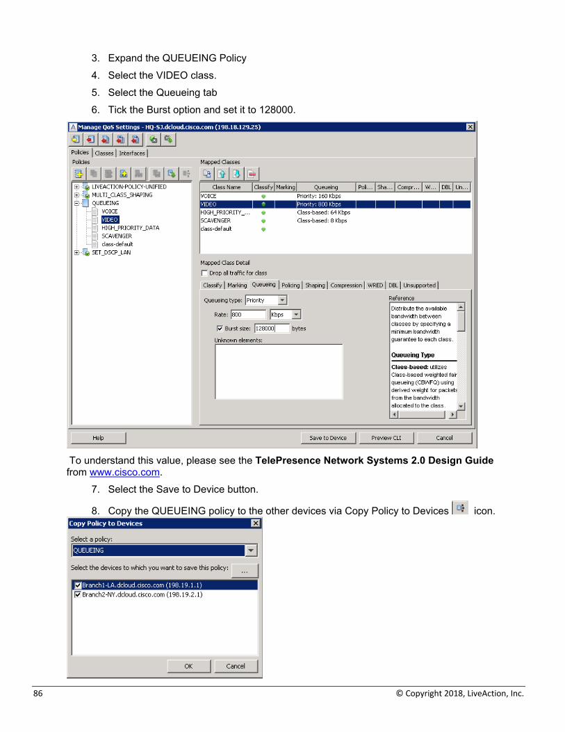
3. Expand the QUEUEING Policy 4. Select the VIDEO class. 5. Select the Queueing tab 6. Tick the Burst option and set it to 128000.
To understand this value, please see the TelePresence Network Systems 2.0 Design Guide from www.cisco.com.
7. Select the Save to Device button.
8. Copy the QUEUEING policy to the other devices via Copy Policy to Devices icon.
LiveAction Lab Workbook
87
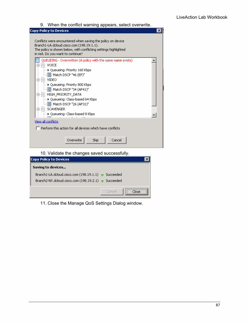
9. When the conflict warning appears, select overwrite.
10. Validate the changes saved successfully.
11. Close the Manage QoS Settings Dialog window.

88 © Copyright 2018, LiveAction, Inc.
Lab 7: QoS Alerts
LiveAction Lab Workbook
89
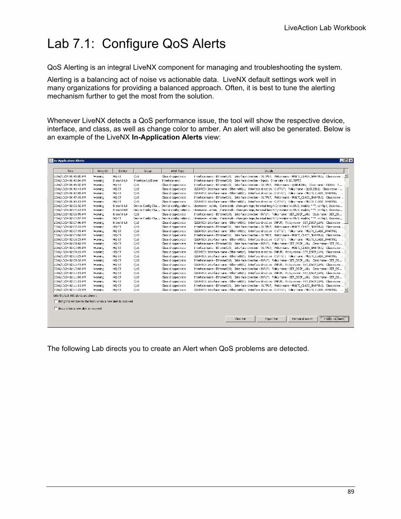
Lab 7.1: Configure QoS Alerts QoS Alerting is an integral LiveNX component for managing and troubleshooting the system. Alerting is a balancing act of noise vs actionable data. LiveNX default settings work well in many organizations for providing a balanced approach. Often, it is best to tune the alerting mechanism further to get the most from the solution. Whenever LiveNX detects a QoS performance issue, the tool will show the respective device, interface, and class, as well as change color to amber. An alert will also be generated. Below is an example of the LiveNX In-Application Alerts view:
The following Lab directs you to create an Alert when QoS problems are detected.
90 © Copyright 2018, LiveAction, Inc.
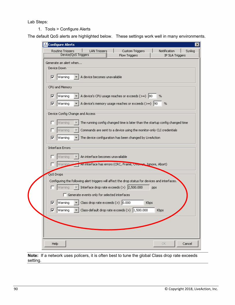
Lab Steps: 1. Tools > Configure Alerts
The default QoS alerts are highlighted below. These settings work well in many environments.
Note: If a network uses policers, it is often best to tune the global Class drop rate exceeds setting.
LiveAction Lab Workbook
91
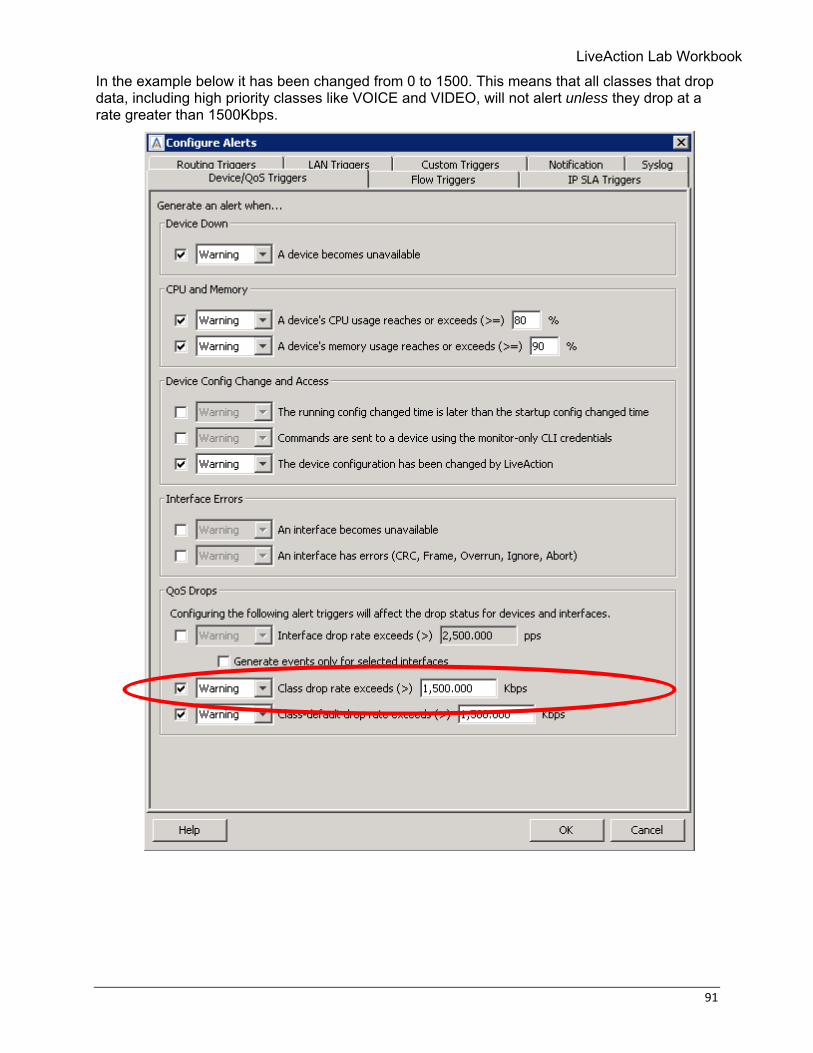
In the example below it has been changed from 0 to 1500. This means that all classes that drop data, including high priority classes like VOICE and VIDEO, will not alert unless they drop at a rate greater than 1500Kbps.
92 © Copyright 2018, LiveAction, Inc.
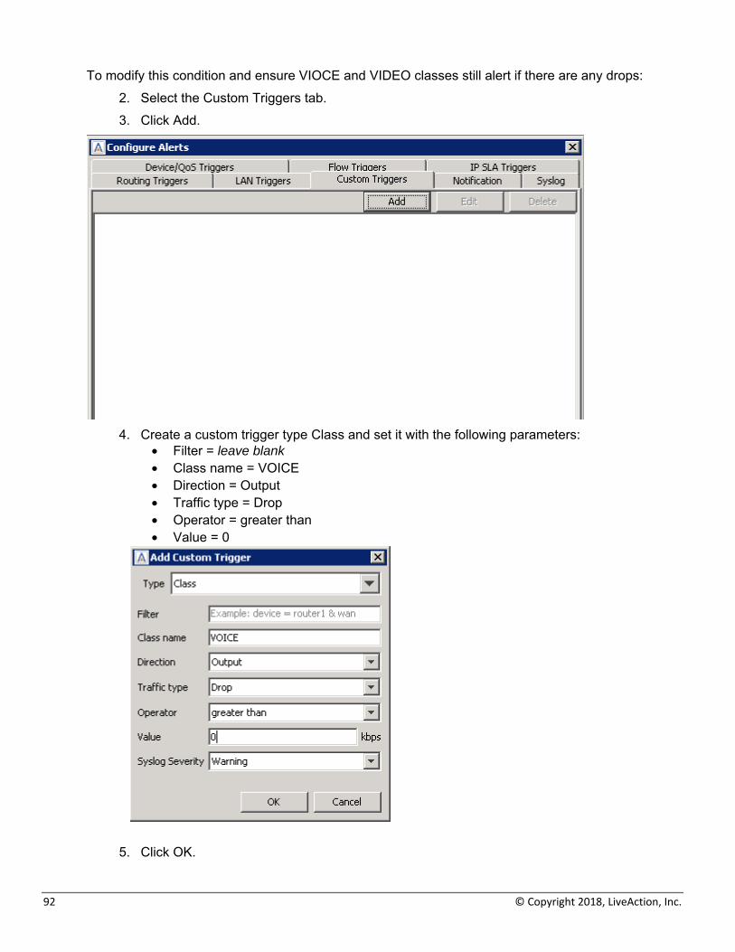
To modify this condition and ensure VIOCE and VIDEO classes still alert if there are any drops: 2. Select the Custom Triggers tab. 3. Click Add.
4. Create a custom trigger type Class and set it with the following parameters:
• Filter = leave blank • Class name = VOICE • Direction = Output • Traffic type = Drop • Operator = greater than • Value = 0
5. Click OK.
LiveAction Lab Workbook
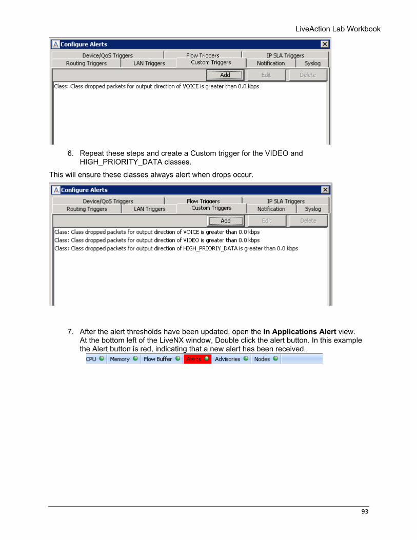
93
6. Repeat these steps and create a Custom trigger for the VIDEO and
HIGH_PRIORITY_DATA classes. This will ensure these classes always alert when drops occur.
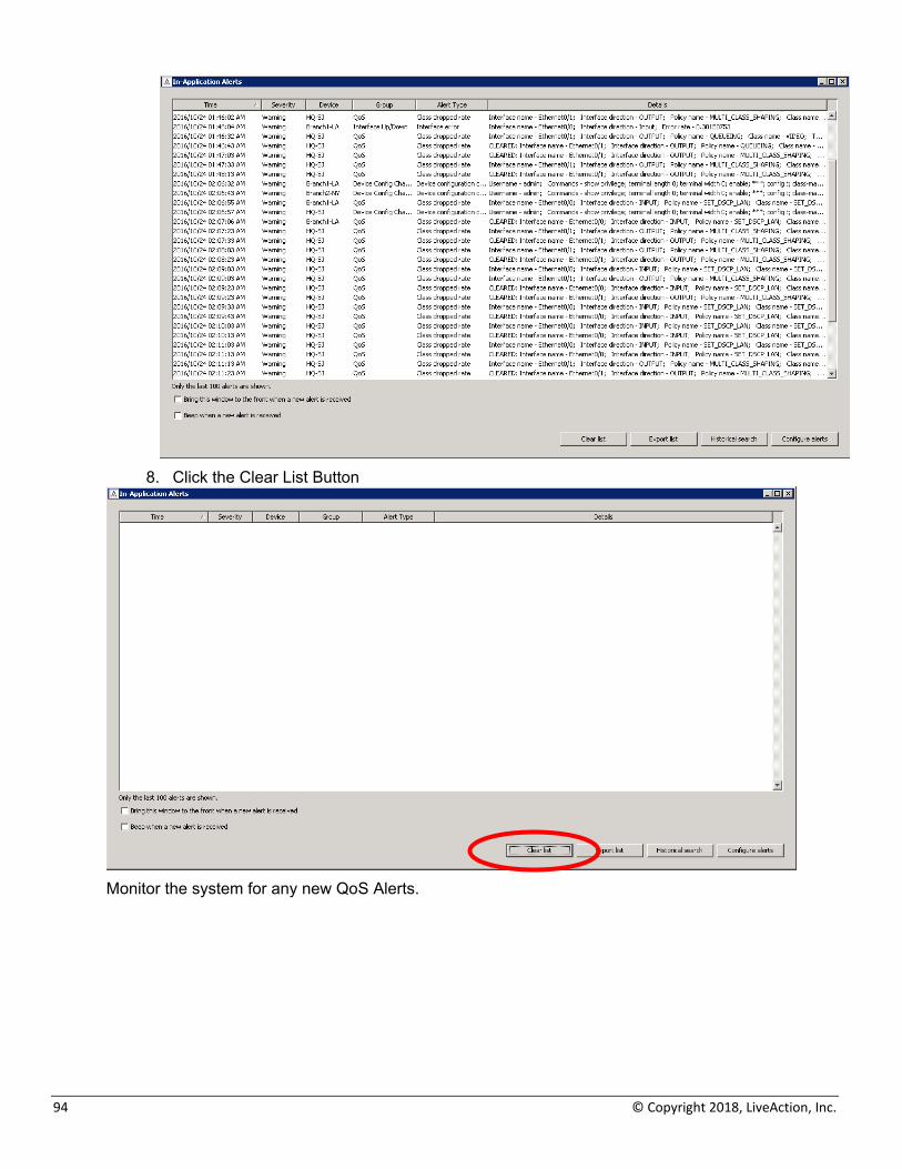
7. After the alert thresholds have been updated, open the In Applications Alert view. At the bottom left of the LiveNX window, Double click the alert button. In this example the Alert button is red, indicating that a new alert has been received.
94 © Copyright 2018, LiveAction, Inc.
8. Click the Clear List Button
Monitor the system for any new QoS Alerts.
LiveAction Lab Workbook
95
Lab 8: Configure PfRv3 Monitoring
96 © Copyright 2018, LiveAction, Inc.
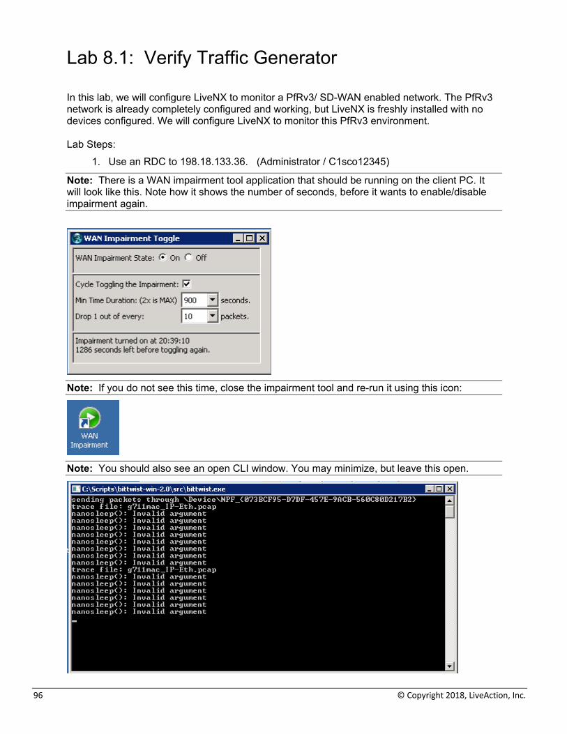
Lab 8.1: Verify Traffic Generator In this lab, we will configure LiveNX to monitor a PfRv3/ SD-WAN enabled network. The PfRv3 network is already completely configured and working, but LiveNX is freshly installed with no devices configured. We will configure LiveNX to monitor this PfRv3 environment. Lab Steps:
1. Use an RDC to 198.18.133.36. (Administrator / C1sco12345)
Note: There is a WAN impairment tool application that should be running on the client PC. It will look like this. Note how it shows the number of seconds, before it wants to enable/disable impairment again.
Note: If you do not see this time, close the impairment tool and re-run it using this icon:
Note: You should also see an open CLI window. You may minimize, but leave this open.
LiveAction Lab Workbook
97
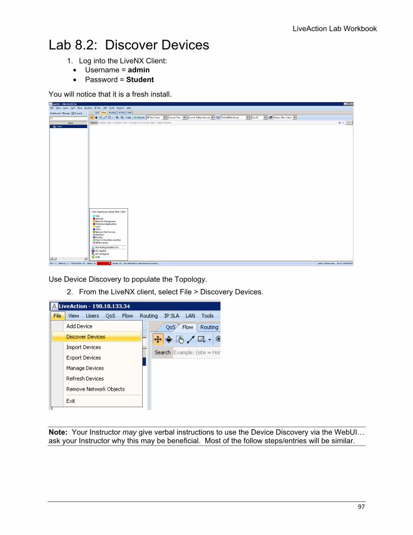
Lab 8.2: Discover Devices 1. Log into the LiveNX Client:
• Username = admin • Password = Student
You will notice that it is a fresh install.
Use Device Discovery to populate the Topology.
2. From the LiveNX client, select File > Discovery Devices.
Note: Your Instructor may give verbal instructions to use the Device Discovery via the WebUI… ask your Instructor why this may be beneficial. Most of the follow steps/entries will be similar.
98 © Copyright 2018, LiveAction, Inc.
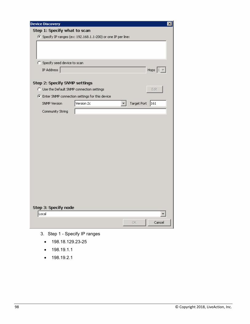
3. Step 1 - Specify IP ranges
• 198.18.129.23-25
• 198.19.1.1
• 198.19.2.1
LiveAction Lab Workbook
99
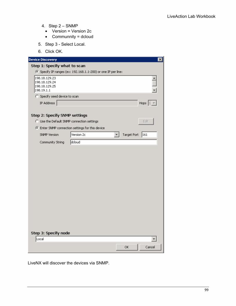
4. Step 2 – SNMP • Version = Version 2c • Communnity = dcloud
5. Step 3 - Select Local. 6. Click OK.
LiveNX will discover the devices via SNMP.
100 © Copyright 2018, LiveAction, Inc.
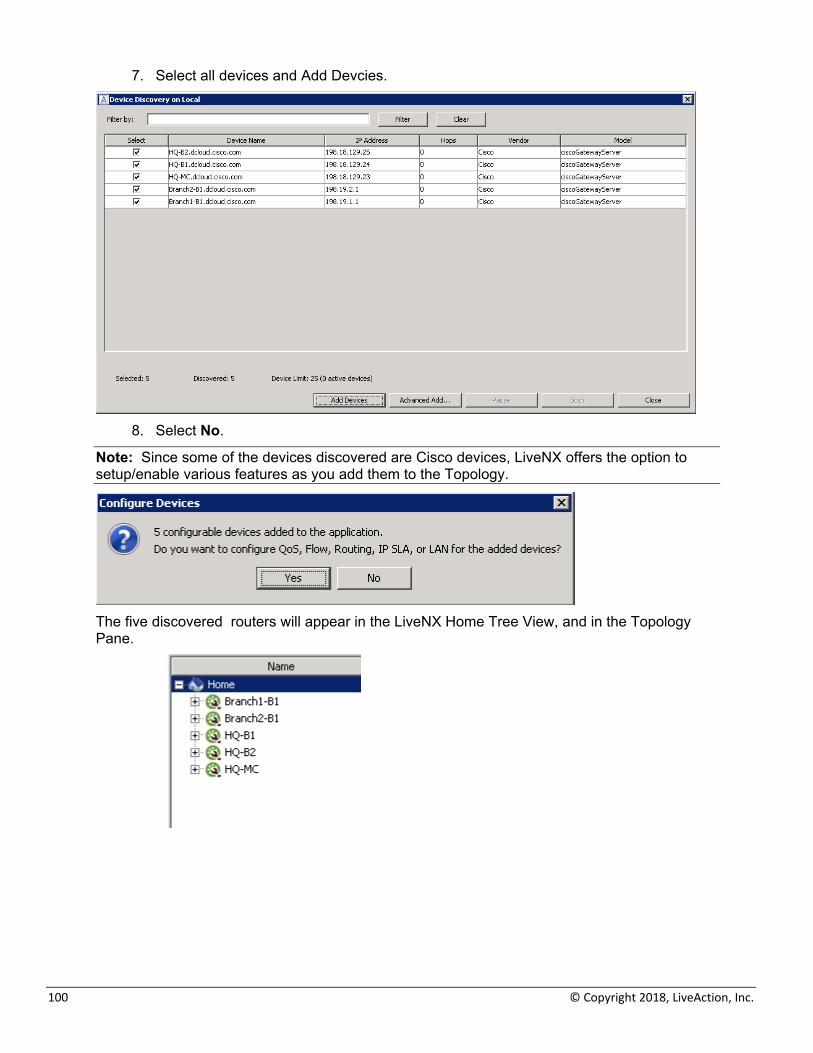
7. Select all devices and Add Devcies.
8. Select No.
Note: Since some of the devices discovered are Cisco devices, LiveNX offers the option to setup/enable various features as you add them to the Topology.
The five discovered routers will appear in the LiveNX Home Tree View, and in the Topology Pane.
LiveAction Lab Workbook
101
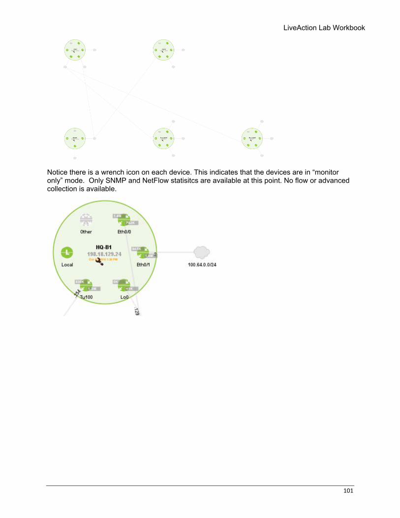
Notice there is a wrench icon on each device. This indicates that the devices are in “monitor only” mode. Only SNMP and NetFlow statisitcs are available at this point. No flow or advanced collection is available.
102 © Copyright 2018, LiveAction, Inc.
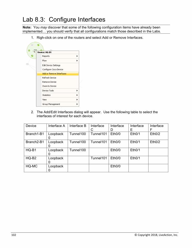
Lab 8.3: Configure Interfaces Note: You may discover that some of the following configuration items have already been implemented… you should verify that all configurations match those described in the Labs.
1. Righ-click on one of the routers and select Add or Remove Interfaces.
2. The Add/Edit Interfaces dialog will appear. Use the following table to select the
interfaces of interest for each device.
Device Interface A Interface B Interface C
Interface D
Interface E
Interface F
Branch1-B1 Loopback 0
Tunnel100 Tunnel101 Eth0/0 Eth0/1 Eth0/2
Branch2-B1 Loopback 0
Tunnel100 Tunnel101 Eth0/0 Eth0/1 Eth0/2
HQ-B1 Loopback 0
Tunnel100 Eth0/0 Eth0/1
HQ-B2 Loopback 0
Tunnel101 Eth0/0 Eth0/1
HQ-MC Loopback 0
Eth0/0
LiveAction Lab Workbook
103
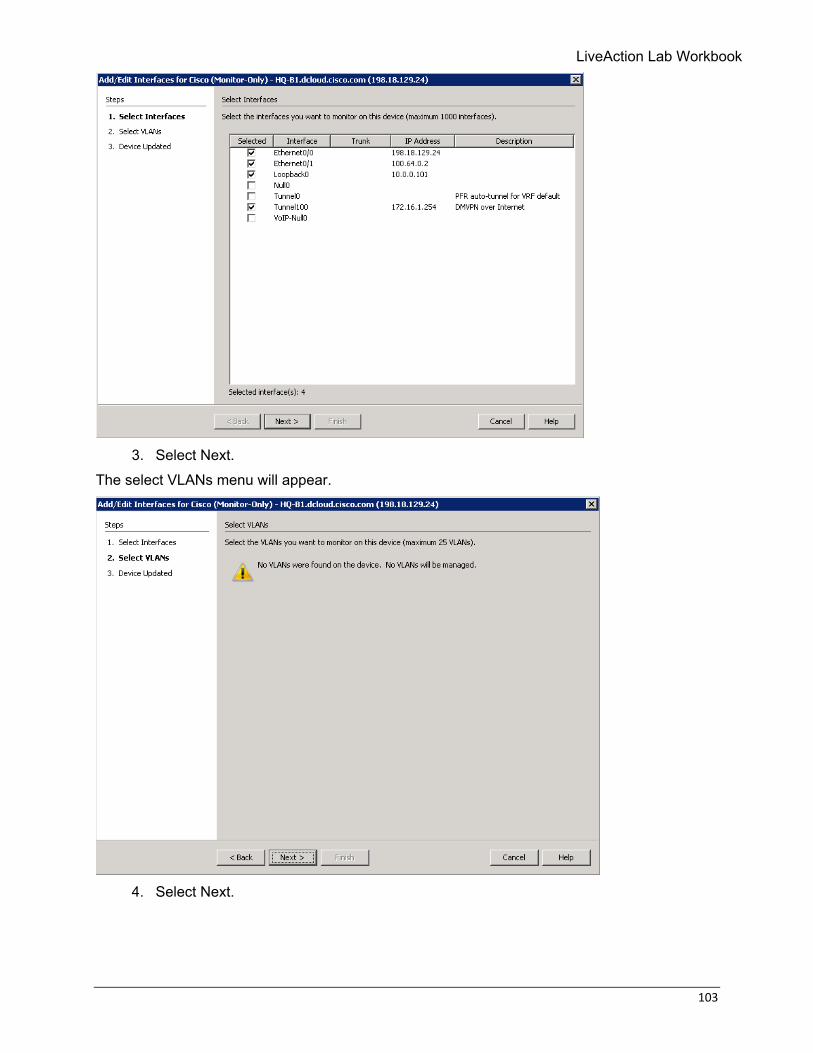
3. Select Next.
The select VLANs menu will appear.
4. Select Next.
104 © Copyright 2018, LiveAction, Inc.
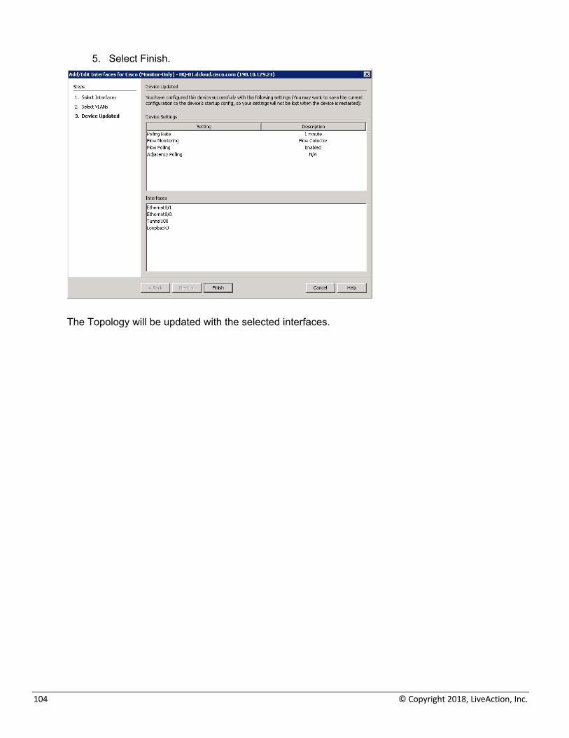
5. Select Finish.
The Topology will be updated with the selected interfaces.
LiveAction Lab Workbook
105
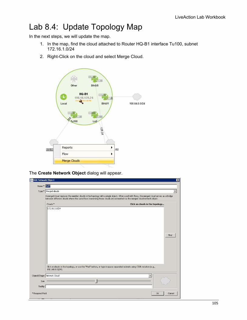
Lab 8.4: Update Topology Map In the next steps, we will update the map.
1. In the map, find the cloud attached to Router HQ-B1 interface Tu100, subnet 172.16.1.0/24
2. Right-Click on the cloud and select Merge Cloud.
The Create Network Object dialog will appear.

106 © Copyright 2018, LiveAction, Inc.
3. Update the name to: INET 4. Update Object/Shape: Network Cloud
A large grey cloud will appear on the Topology.
5. Locate the cloud attached to Router HQ-B2 interface Tu101, subnet 172.16.2.0/24 6. Right-Click on the cloud and select Merge Cloud.
LiveAction Lab Workbook
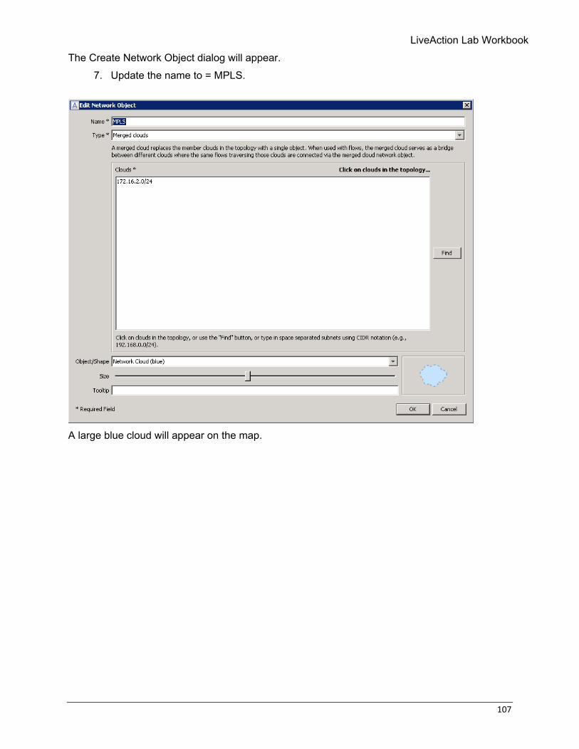
107
The Create Network Object dialog will appear. 7. Update the name to = MPLS.
A large blue cloud will appear on the map.
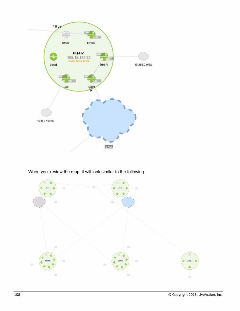
108 © Copyright 2018, LiveAction, Inc.
When you review the map, it will look similar to the following.
LiveAction Lab Workbook
109
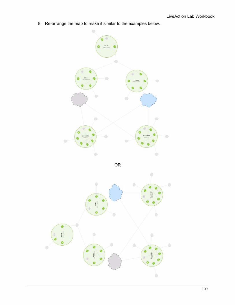
8. Re-arrange the map to make it similar to the examples below.
OR
110 © Copyright 2018, LiveAction, Inc.
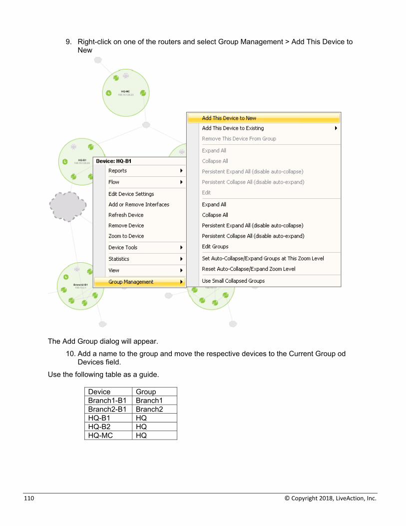
9. Right-click on one of the routers and select Group Management > Add This Device to New
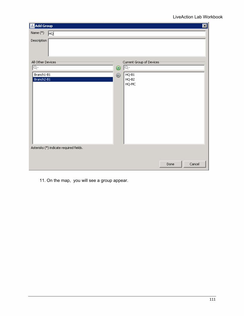
The Add Group dialog will appear.
10. Add a name to the group and move the respective devices to the Current Group od Devices field.
Use the following table as a guide.
Device Group Branch1-B1 Branch1 Branch2-B1 Branch2 HQ-B1 HQ HQ-B2 HQ HQ-MC HQ
LiveAction Lab Workbook
111
11. On the map, you will see a group appear.

112 © Copyright 2018, LiveAction, Inc.
12. Double-click on the group to see the member devices again.
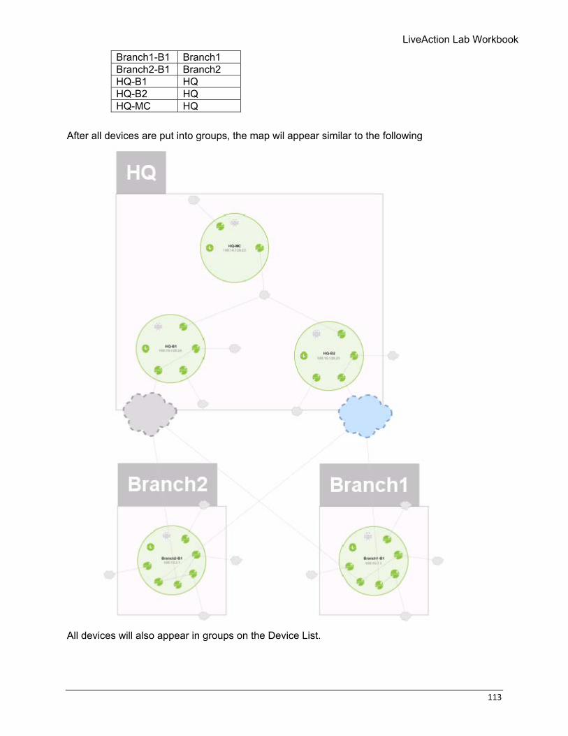
13. Add the other devices to their respective groups based on the following table: Device Group
LiveAction Lab Workbook
113
Branch1-B1 Branch1 Branch2-B1 Branch2 HQ-B1 HQ HQ-B2 HQ HQ-MC HQ
After all devices are put into groups, the map wil appear similar to the following
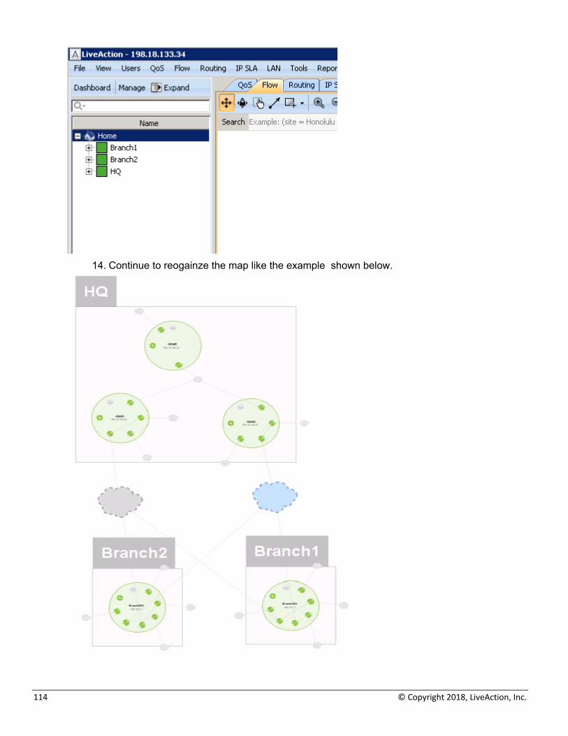
All devices will also appear in groups on the Device List.
114 © Copyright 2018, LiveAction, Inc.
14. Continue to reogainze the map like the example shown below.
LiveAction Lab Workbook
115
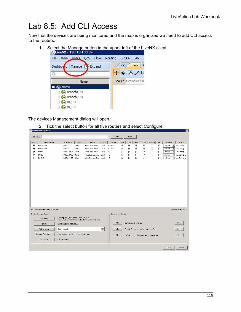
Lab 8.5: Add CLI Access Now that the devices are being monitored and the map is organized we need to add CLI access to the routers.
1. Select the Manage button in the upper left of the LiveNX client.
The devices Management dialog will open.
2. Tick the select button for all five routers and select Configure.
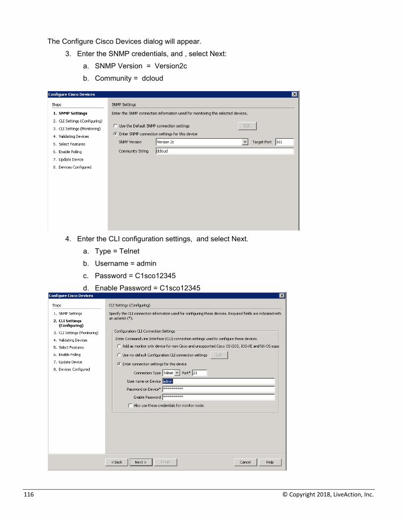
116 © Copyright 2018, LiveAction, Inc.
The Configure Cisco Devices dialog will appear. 3. Enter the SNMP credentials, and , select Next:
a. SNMP Version = Version2c b. Community = dcloud
4. Enter the CLI configuration settings, and select Next.
a. Type = Telnet b. Username = admin c. Password = C1sco12345 d. Enable Password = C1sco12345
LiveAction Lab Workbook
117
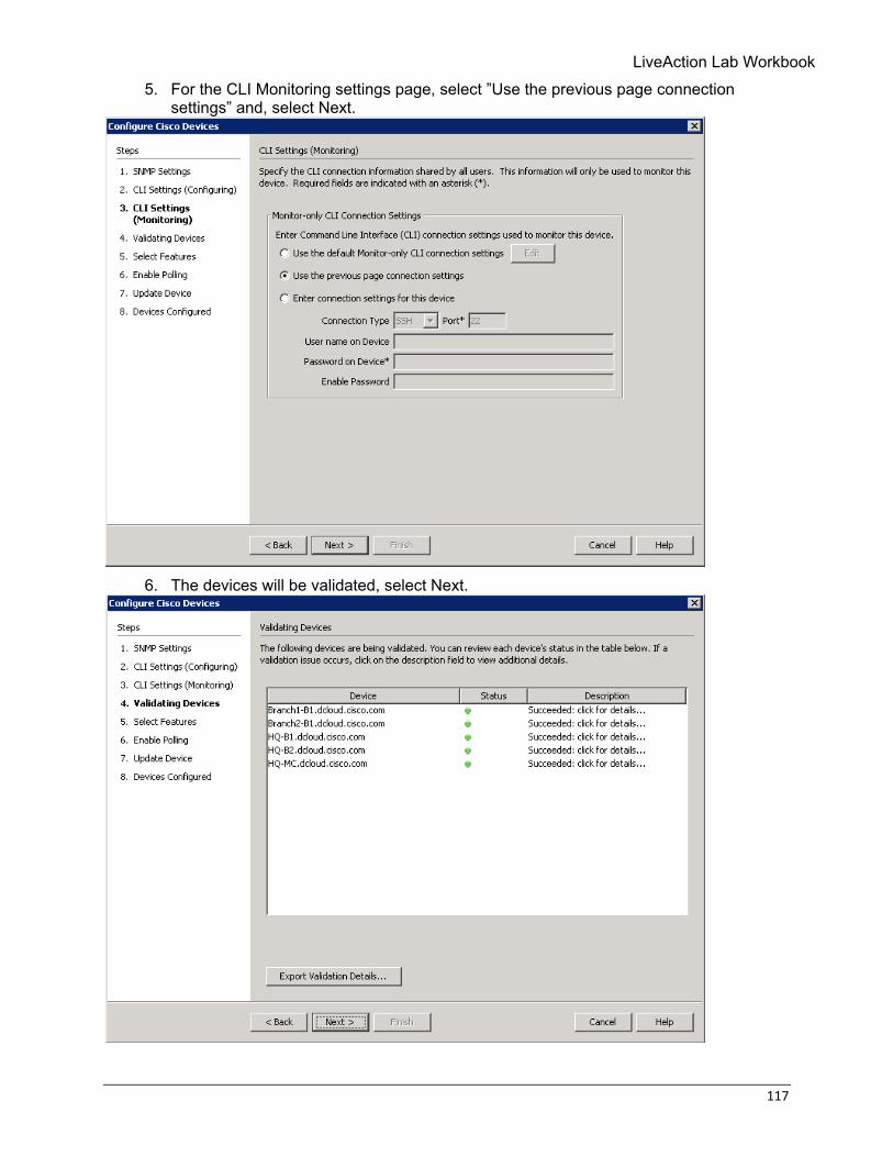
5. For the CLI Monitoring settings page, select ”Use the previous page connection settings” and, select Next.
6. The devices will be validated, select Next.
118 © Copyright 2018, LiveAction, Inc.
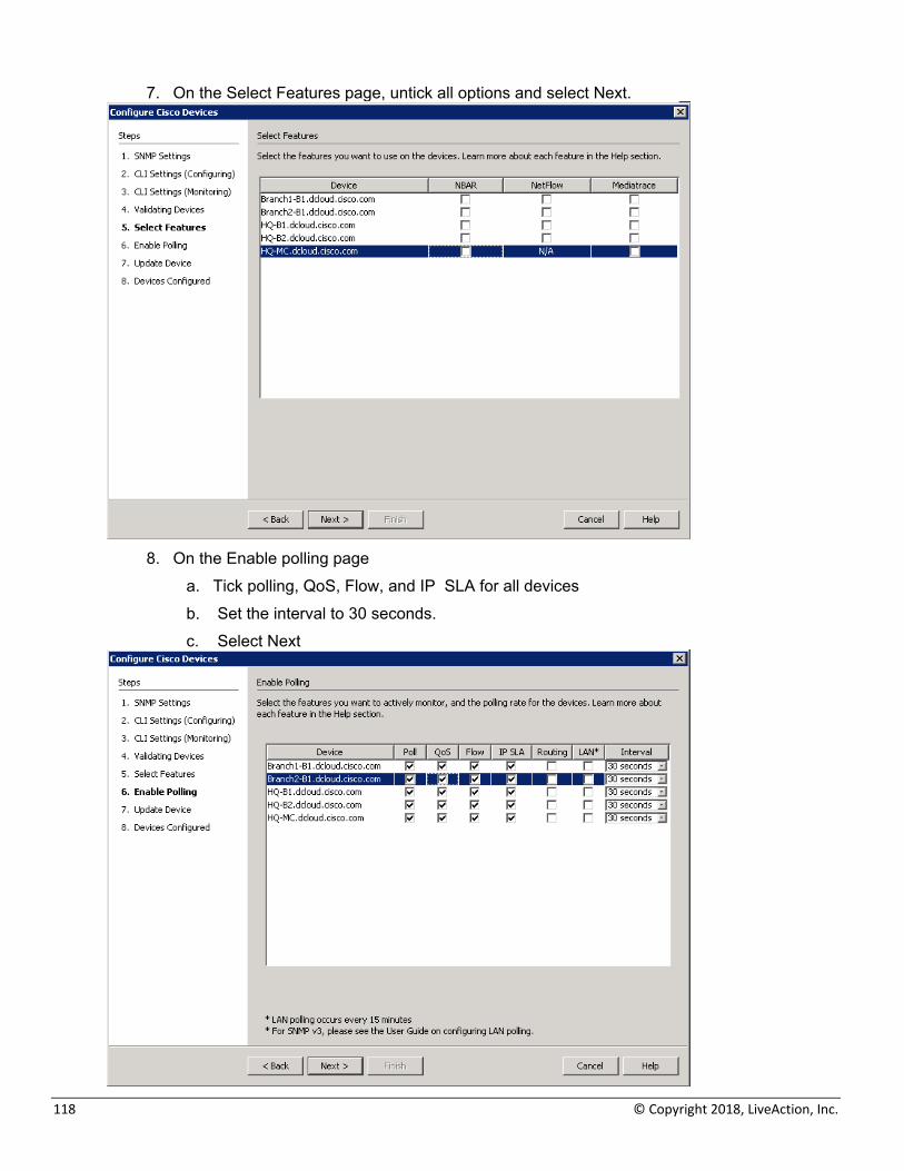
7. On the Select Features page, untick all options and select Next.
8. On the Enable polling page
a. Tick polling, QoS, Flow, and IP SLA for all devices b. Set the interval to 30 seconds. c. Select Next
LiveAction Lab Workbook
119
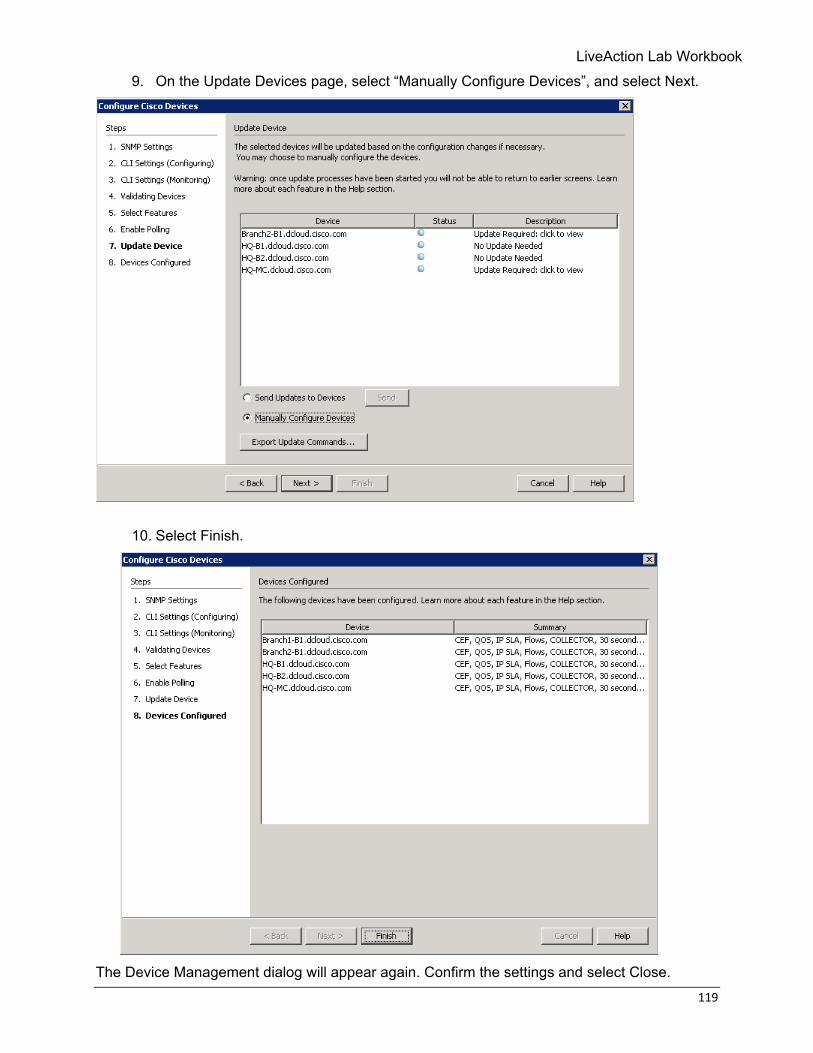
9. On the Update Devices page, select “Manually Configure Devices”, and select Next.
10. Select Finish.
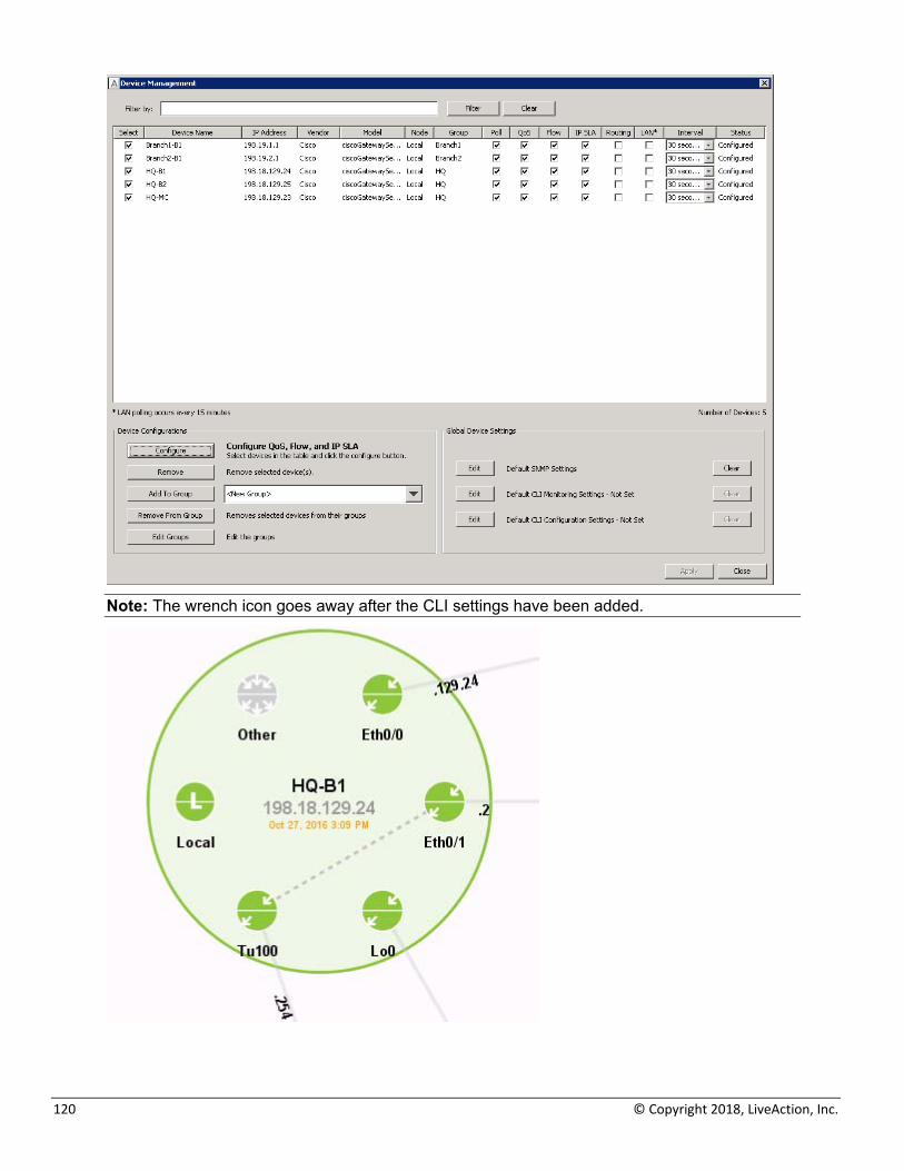
The Device Management dialog will appear again. Confirm the settings and select Close.
120 © Copyright 2018, LiveAction, Inc.
Note: The wrench icon goes away after the CLI settings have been added.
LiveAction Lab Workbook
121
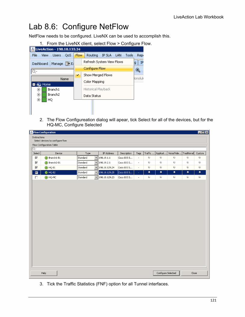
Lab 8.6: Configure NetFlow NetFlow needs to be configured. LiveNX can be used to accomplish this.
1. From the LiveNX client, select Flow > Configure Flow.
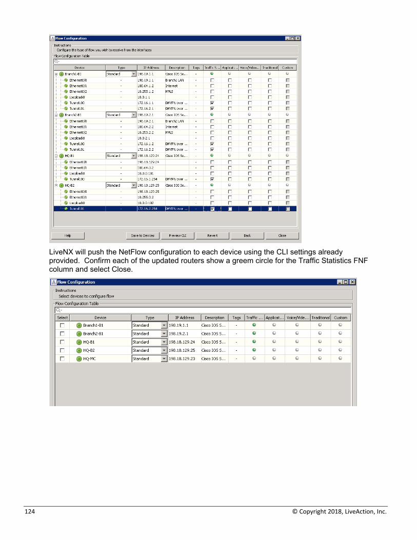
2. The Flow Configureation dialog will apear, tick Select for all of the devices, but for the
HQ-MC, Configure Selected
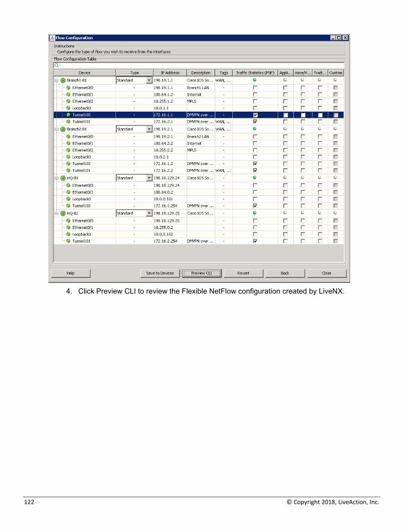
3. Tick the Traffic Statistics (FNF) option for all Tunnel interfaces.
122 © Copyright 2018, LiveAction, Inc.
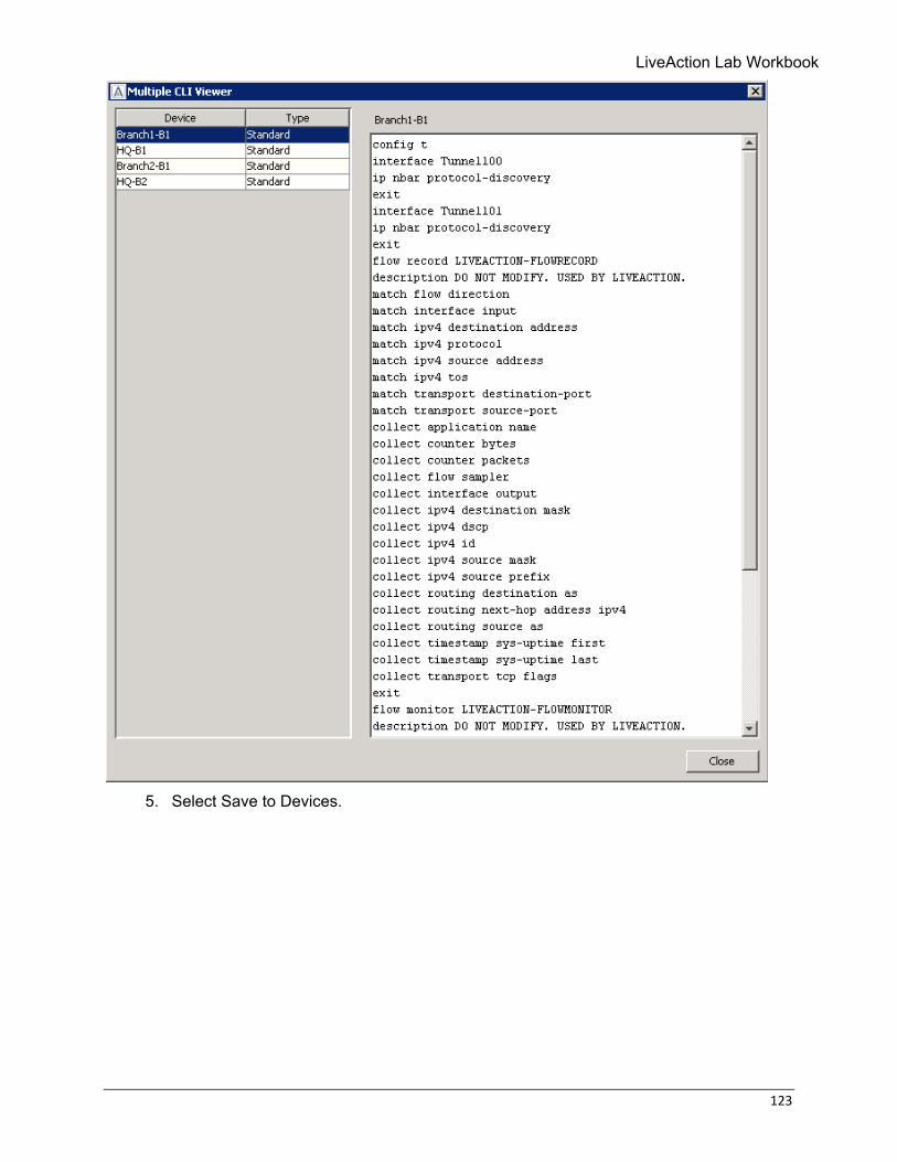
4. Click Preview CLI to review the Flexible NetFlow configuration created by LiveNX.
LiveAction Lab Workbook
123
5. Select Save to Devices.
124 © Copyright 2018, LiveAction, Inc.
LiveNX will push the NetFlow configuration to each device using the CLI settings already provided. Confirm each of the updated routers show a greem circle for the Traffic Statistics FNF column and select Close.
LiveAction Lab Workbook
125
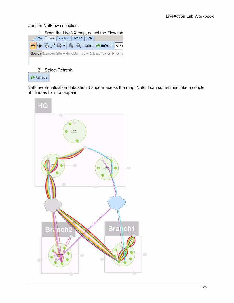
Confirm NetFlow collection. 1. From the LiveNX map, select the Flow tab
2. Select Refresh
NetFlow visualization data should appear across the map. Note it can sometimes take a couple of minutes for it to appear
126 © Copyright 2018, LiveAction, Inc.
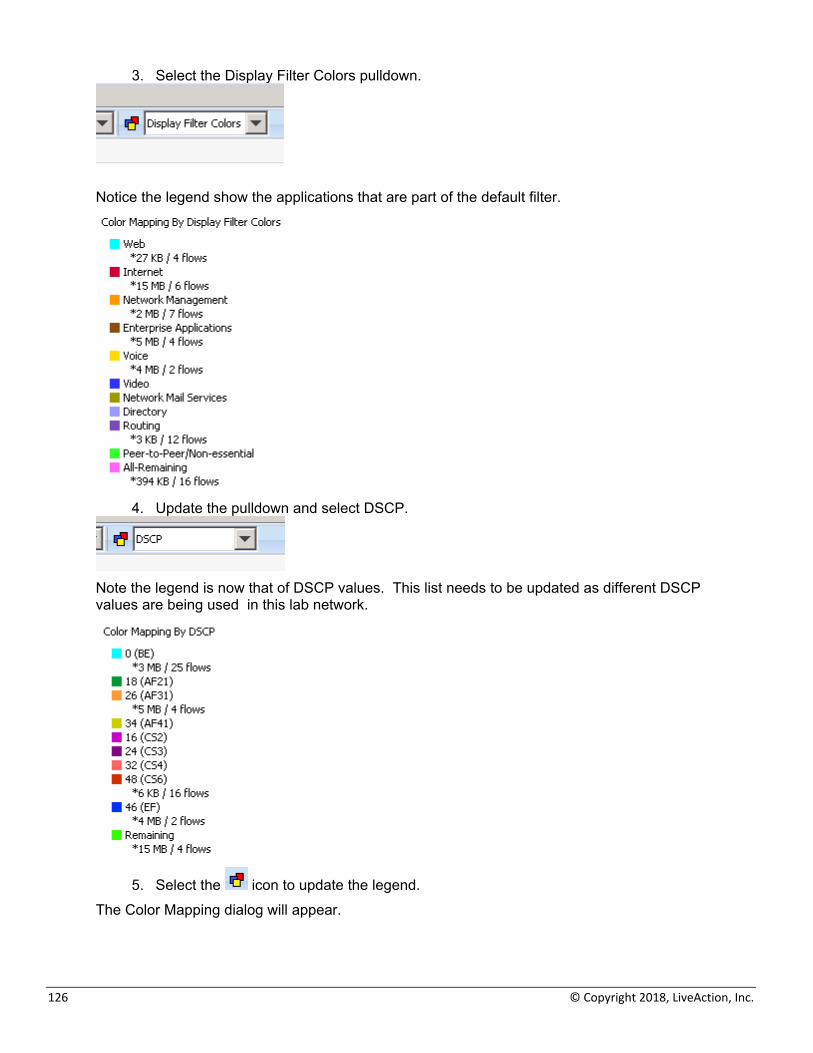
3. Select the Display Filter Colors pulldown.
Notice the legend show the applications that are part of the default filter.
4. Update the pulldown and select DSCP.
Note the legend is now that of DSCP values. This list needs to be updated as different DSCP values are being used in this lab network.
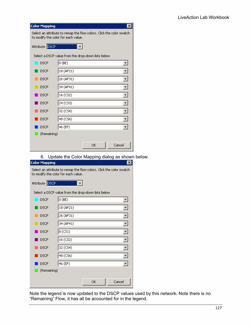
5. Select the icon to update the legend. The Color Mapping dialog will appear.
LiveAction Lab Workbook
127
6. Update the Color Mapping dialog as shown below.
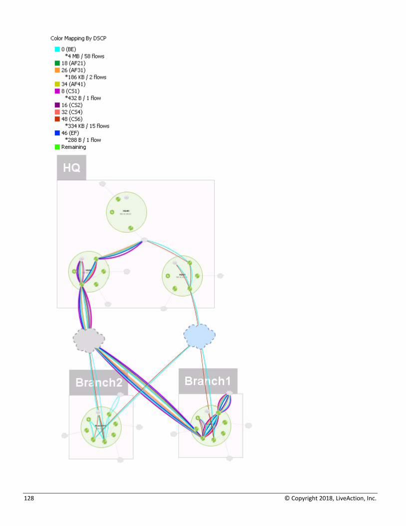
Note the legend is now updated to the DSCP values used by this network. Note there is no “Remaining” Flow, it has all be accounted for in the legend.
128 © Copyright 2018, LiveAction, Inc.
LiveAction Lab Workbook
129
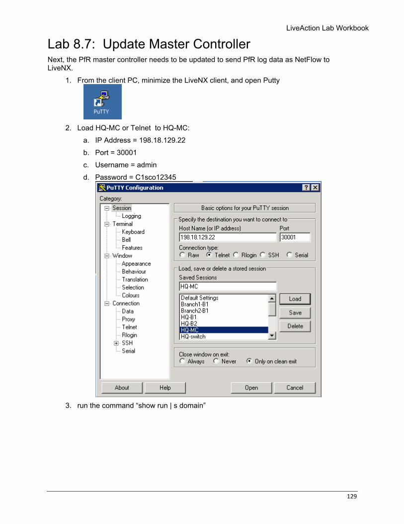
Lab 8.7: Update Master Controller Next, the PfR master controller needs to be updated to send PfR log data as NetFlow to LiveNX.
1. From the client PC, minimize the LiveNX client, and open Putty
2. Load HQ-MC or Telnet to HQ-MC:
a. IP Address = 198.18.129.22 b. Port = 30001 c. Username = admin d. Password = C1sco12345
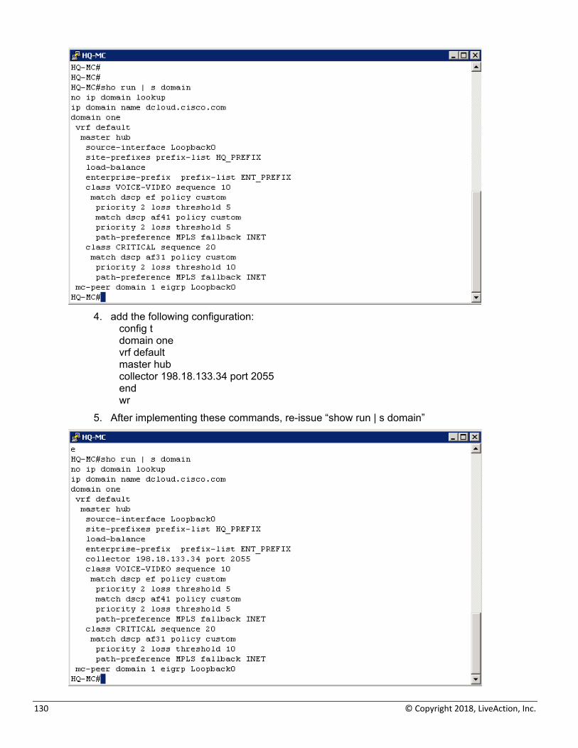
3. run the command “show run | s domain”
130 © Copyright 2018, LiveAction, Inc.
4. add the following configuration:
config t domain one vrf default master hub collector 198.18.133.34 port 2055 end wr
5. After implementing these commands, re-issue “show run | s domain”
LiveAction Lab Workbook
131
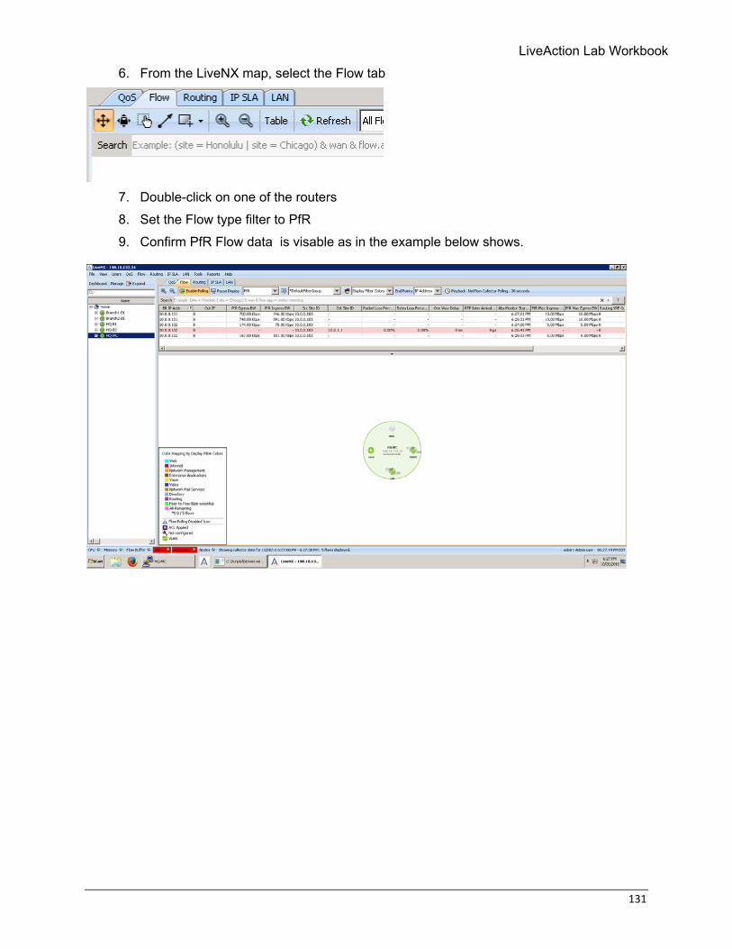
6. From the LiveNX map, select the Flow tab
7. Double-click on one of the routers 8. Set the Flow type filter to PfR 9. Confirm PfR Flow data is visable as in the example below shows.
132 © Copyright 2018, LiveAction, Inc.
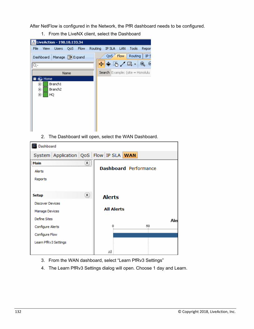
After NetFlow is configured in the Network, the PfR dashboard needs to be configured. 1. From the LiveNX client, select the Dashboard
2. The Dashboard will open, select the WAN Dashboard.
3. From the WAN dashboard, select “Learn PfRv3 Settings” 4. The Learn PfRv3 Settings dialog will open. Choose 1 day and Learn.
LiveAction Lab Workbook
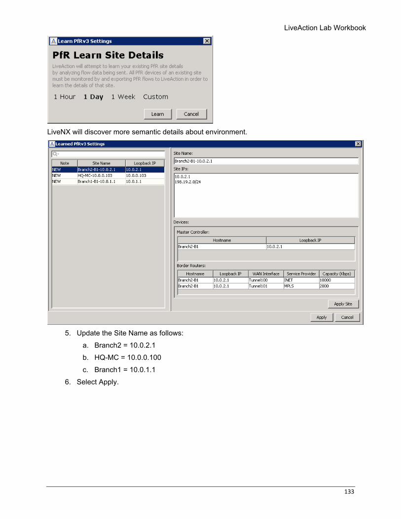
133
LiveNX will discover more semantic details about environment.
5. Update the Site Name as follows:
a. Branch2 = 10.0.2.1 b. HQ-MC = 10.0.0.100 c. Branch1 = 10.0.1.1
6. Select Apply.
134 © Copyright 2018, LiveAction, Inc.
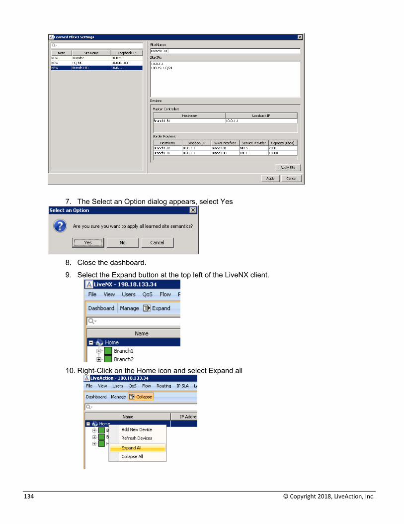
7. The Select an Option dialog appears, select Yes
8. Close the dashboard. 9. Select the Expand button at the top left of the LiveNX client.
10. Right-Click on the Home icon and select Expand all
LiveAction Lab Workbook
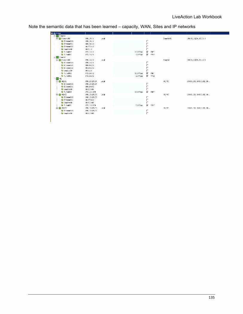
135
Note the semantic data that has been learned – capacity, WAN, Sites and IP networks
136 © Copyright 2018, LiveAction, Inc.
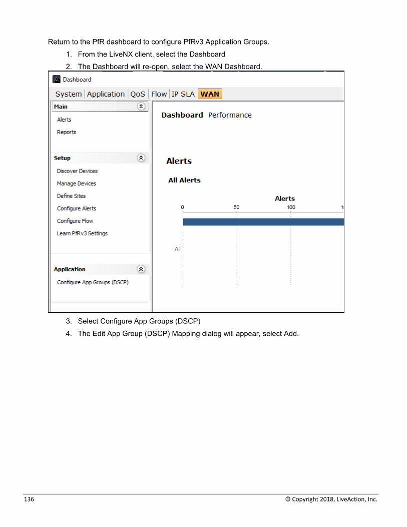
Return to the PfR dashboard to configure PfRv3 Application Groups. 1. From the LiveNX client, select the Dashboard 2. The Dashboard will re-open, select the WAN Dashboard.
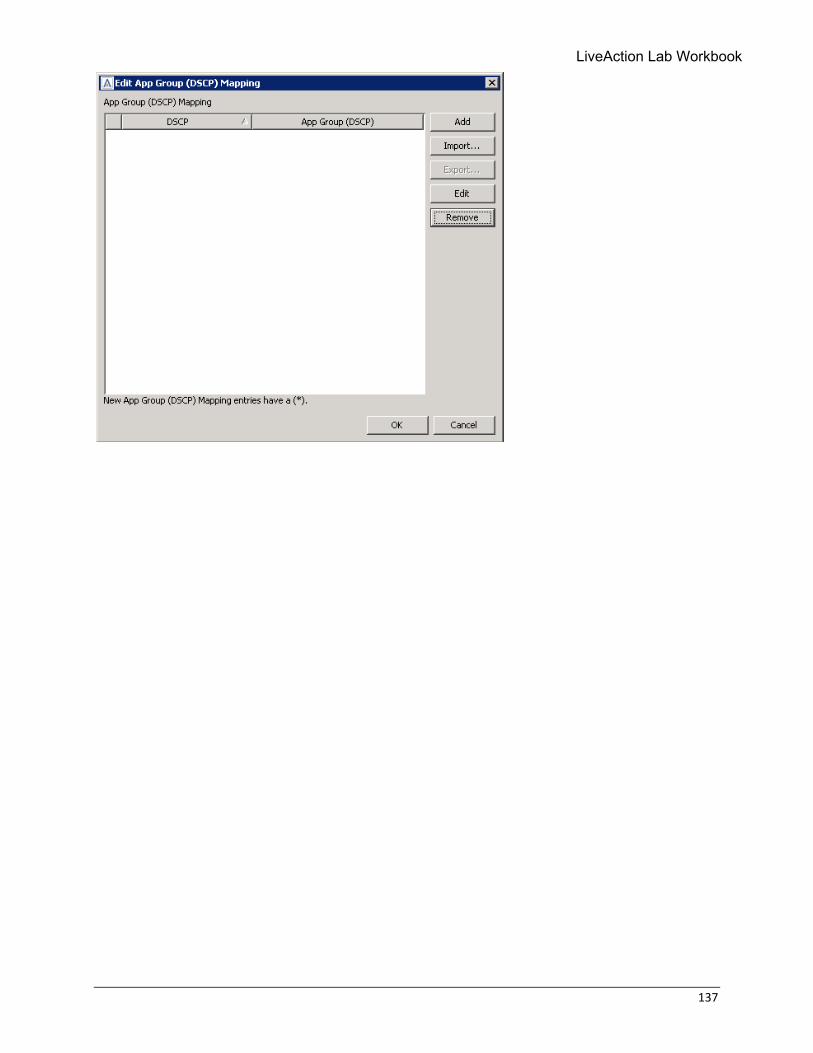
3. Select Configure App Groups (DSCP) 4. The Edit App Group (DSCP) Mapping dialog will appear, select Add.
LiveAction Lab Workbook
137
138 © Copyright 2018, LiveAction, Inc.
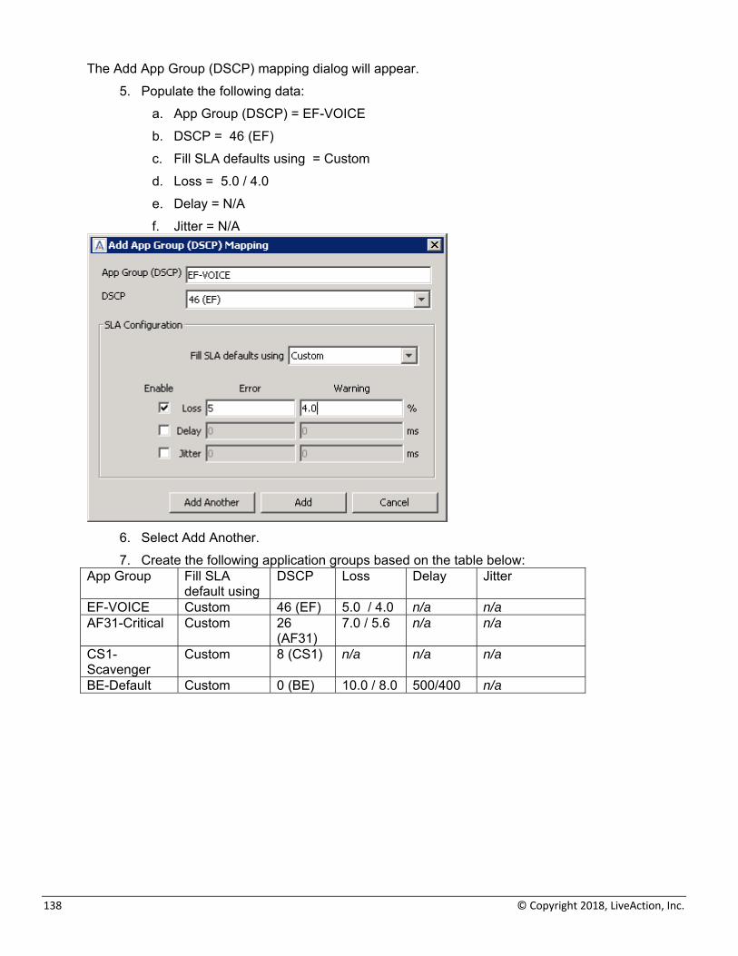
The Add App Group (DSCP) mapping dialog will appear. 5. Populate the following data:
a. App Group (DSCP) = EF-VOICE b. DSCP = 46 (EF) c. Fill SLA defaults using = Custom d. Loss = 5.0 / 4.0 e. Delay = N/A f. Jitter = N/A
6. Select Add Another. 7. Create the following application groups based on the table below:
App Group Fill SLA default using
DSCP Loss Delay Jitter
EF-VOICE Custom 46 (EF) 5.0 / 4.0 n/a n/a AF31-Critical Custom 26
(AF31)7.0 / 5.6 n/a n/a
CS1-Scavenger
Custom 8 (CS1) n/a n/a n/a
BE-Default Custom 0 (BE) 10.0 / 8.0 500/400 n/a
LiveAction Lab Workbook
139
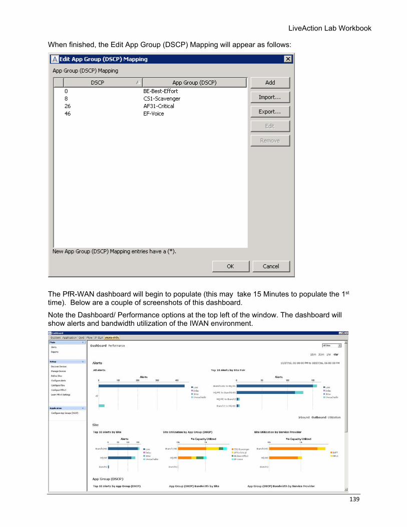
When finished, the Edit App Group (DSCP) Mapping will appear as follows:
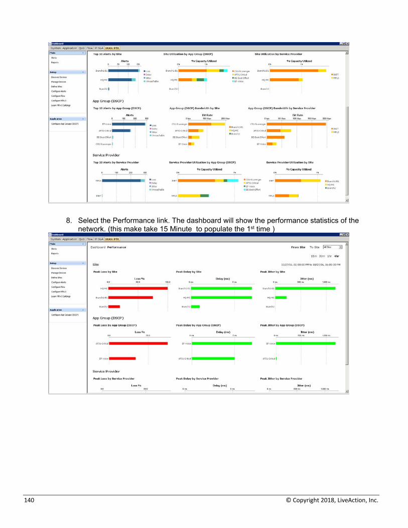
The PfR-WAN dashboard will begin to populate (this may take 15 Minutes to populate the 1st time). Below are a couple of screenshots of this dashboard. Note the Dashboard/ Performance options at the top left of the window. The dashboard will show alerts and bandwidth utilization of the IWAN environment.
140 © Copyright 2018, LiveAction, Inc.
8. Select the Performance link. The dashboard will show the performance statistics of the network. (this make take 15 Minute to populate the 1st time )
LiveAction Lab Workbook
141
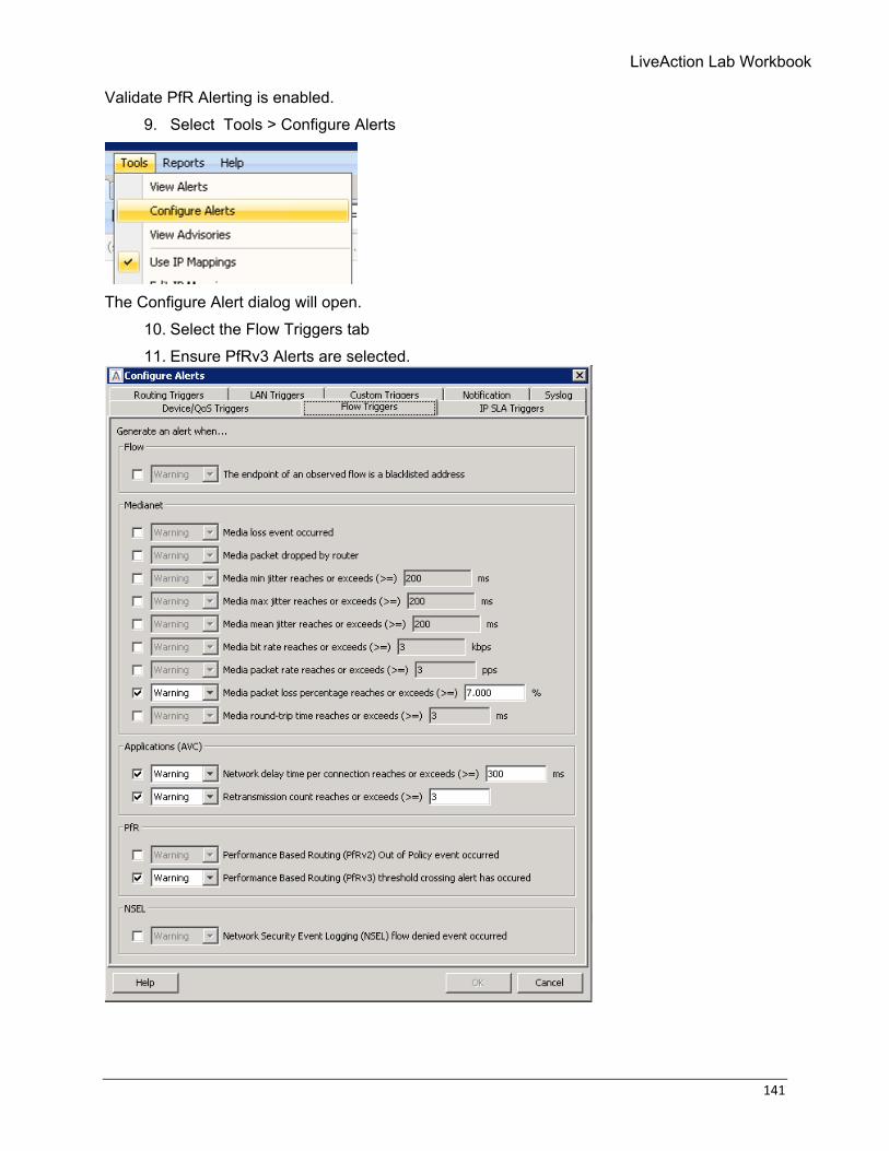
Validate PfR Alerting is enabled. 9. Select Tools > Configure Alerts
The Configure Alert dialog will open.
10. Select the Flow Triggers tab 11. Ensure PfRv3 Alerts are selected.
142 © Copyright 2018, LiveAction, Inc.
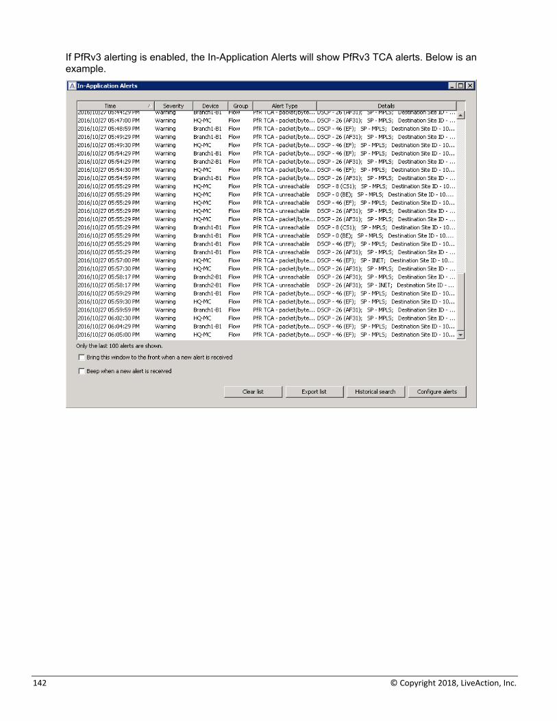
If PfRv3 alerting is enabled, the In-Application Alerts will show PfRv3 TCA alerts. Below is an example.
LiveAction Lab Workbook
143
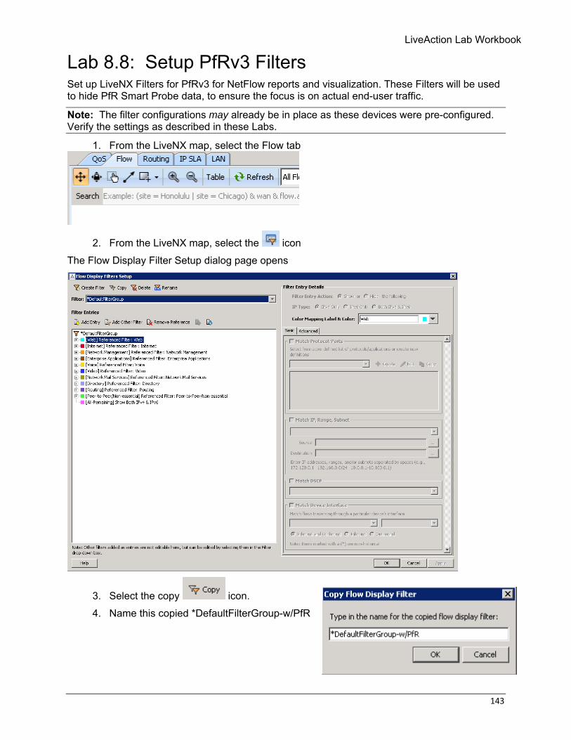
Lab 8.8: Setup PfRv3 Filters Set up LiveNX Filters for PfRv3 for NetFlow reports and visualization. These Filters will be used to hide PfR Smart Probe data, to ensure the focus is on actual end-user traffic.
Note: The filter configurations may already be in place as these devices were pre-configured. Verify the settings as described in these Labs.
1. From the LiveNX map, select the Flow tab
2. From the LiveNX map, select the icon The Flow Display Filter Setup dialog page opens
3. Select the copy icon. 4. Name this copied *DefaultFilterGroup-w/PfR
144 © Copyright 2018, LiveAction, Inc.
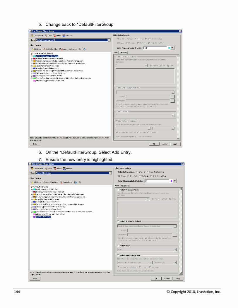
5. Change back to *DefaultFilterGroup
6. On the *DefaultFilterGroup, Select Add Entry. 7. Ensure the new entry is highlighted.
LiveAction Lab Workbook
145
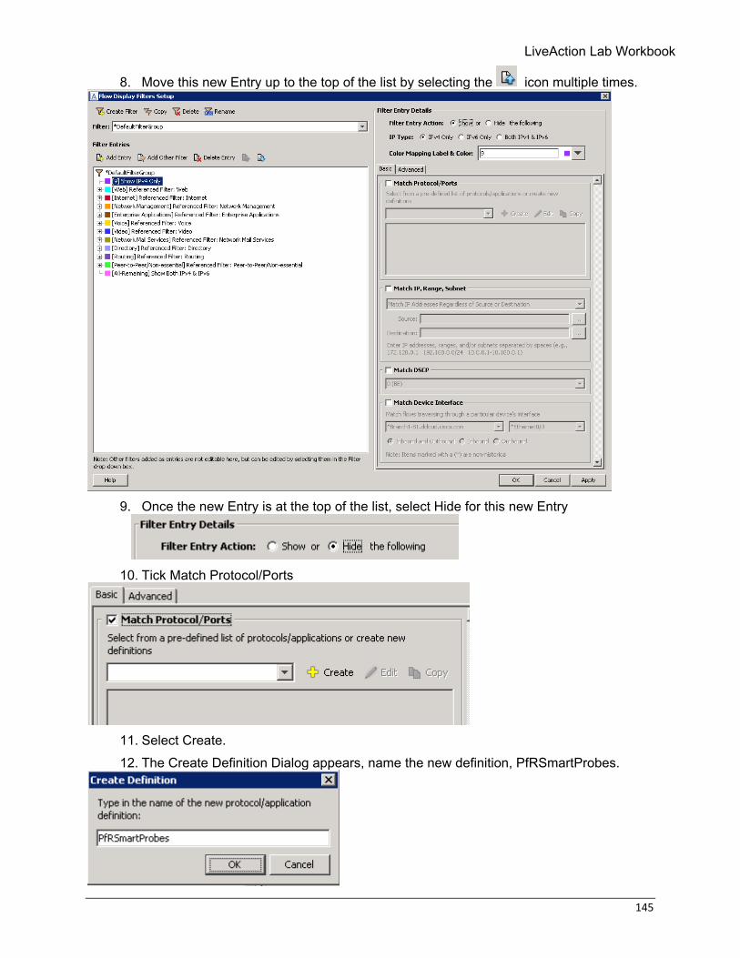
8. Move this new Entry up to the top of the list by selecting the icon multiple times.
9. Once the new Entry is at the top of the list, select Hide for this new Entry
10. Tick Match Protocol/Ports
11. Select Create. 12. The Create Definition Dialog appears, name the new definition, PfRSmartProbes.
146 © Copyright 2018, LiveAction, Inc.
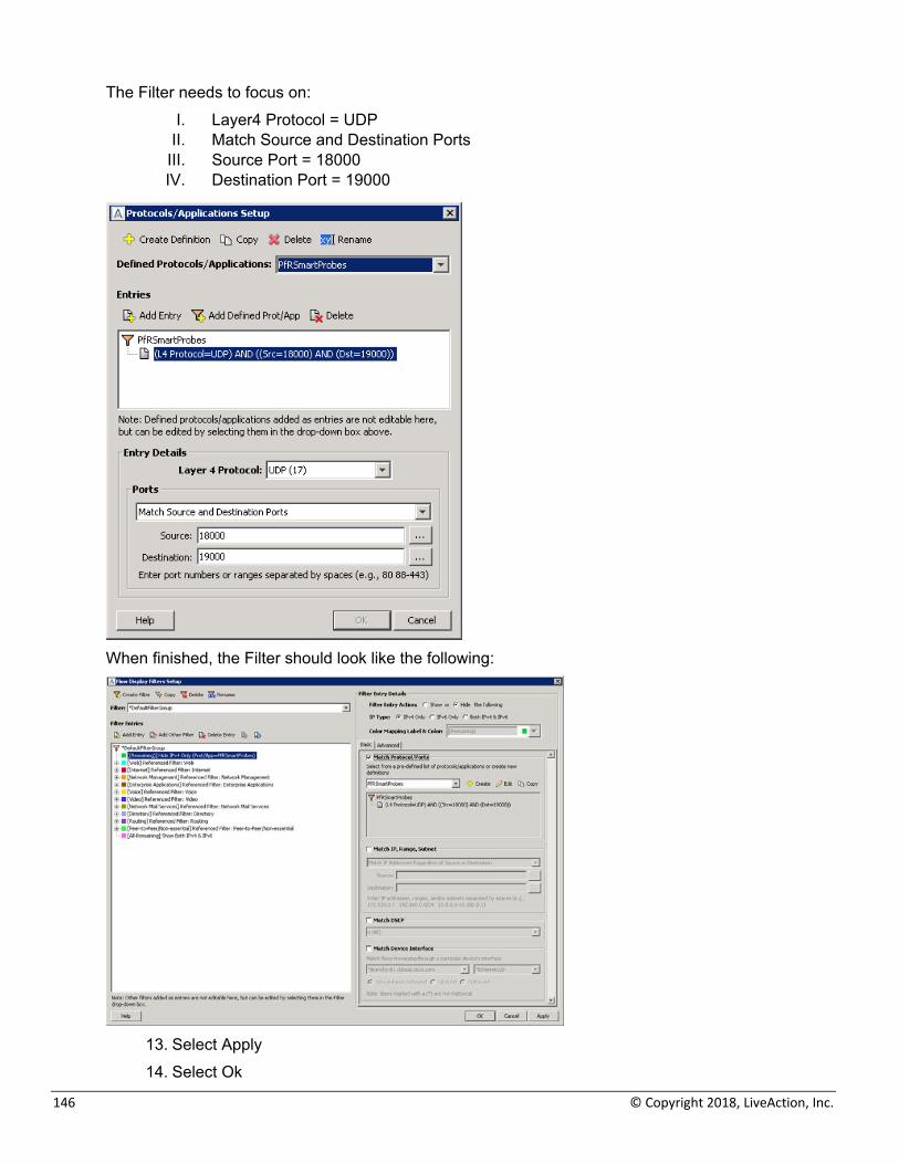
The Filter needs to focus on: I. Layer4 Protocol = UDP
II. Match Source and Destination Ports III. Source Port = 18000 IV. Destination Port = 19000
When finished, the Filter should look like the following:
13. Select Apply 14. Select Ok
LiveAction Lab Workbook
147
Lab 9: SD-WAN Troubleshooting
148 © Copyright 2018, LiveAction, Inc.
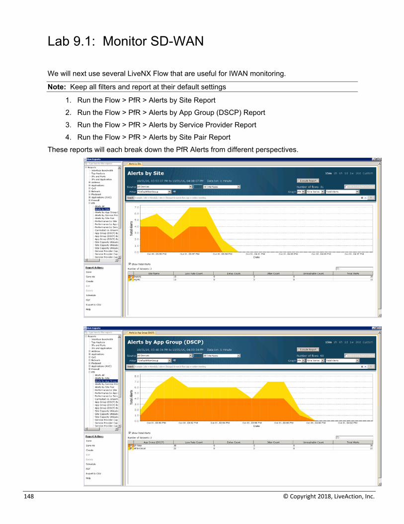
Lab 9.1: Monitor SD-WAN We will next use several LiveNX Flow that are useful for IWAN monitoring.
Note: Keep all filters and report at their default settings
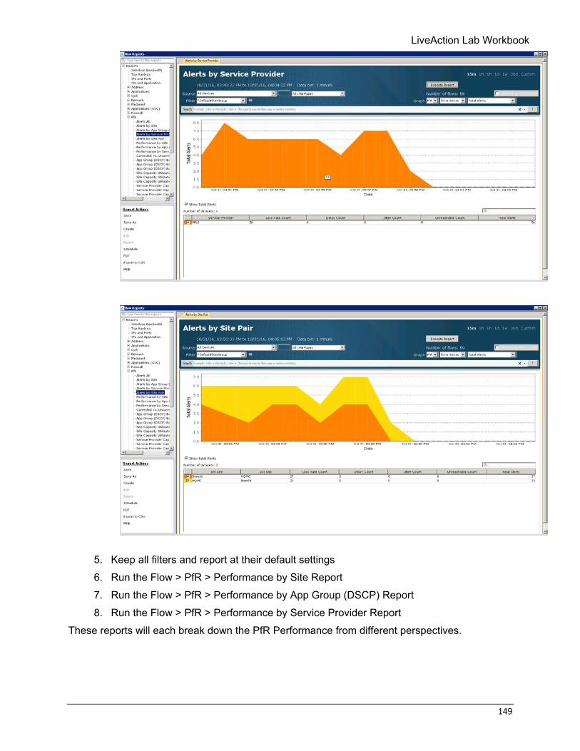
1. Run the Flow > PfR > Alerts by Site Report 2. Run the Flow > PfR > Alerts by App Group (DSCP) Report 3. Run the Flow > PfR > Alerts by Service Provider Report 4. Run the Flow > PfR > Alerts by Site Pair Report
These reports will each break down the PfR Alerts from different perspectives.
LiveAction Lab Workbook
149
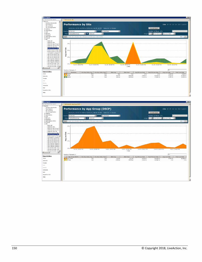
5. Keep all filters and report at their default settings 6. Run the Flow > PfR > Performance by Site Report 7. Run the Flow > PfR > Performance by App Group (DSCP) Report 8. Run the Flow > PfR > Performance by Service Provider Report
These reports will each break down the PfR Performance from different perspectives.
150 © Copyright 2018, LiveAction, Inc.
LiveAction Lab Workbook
151
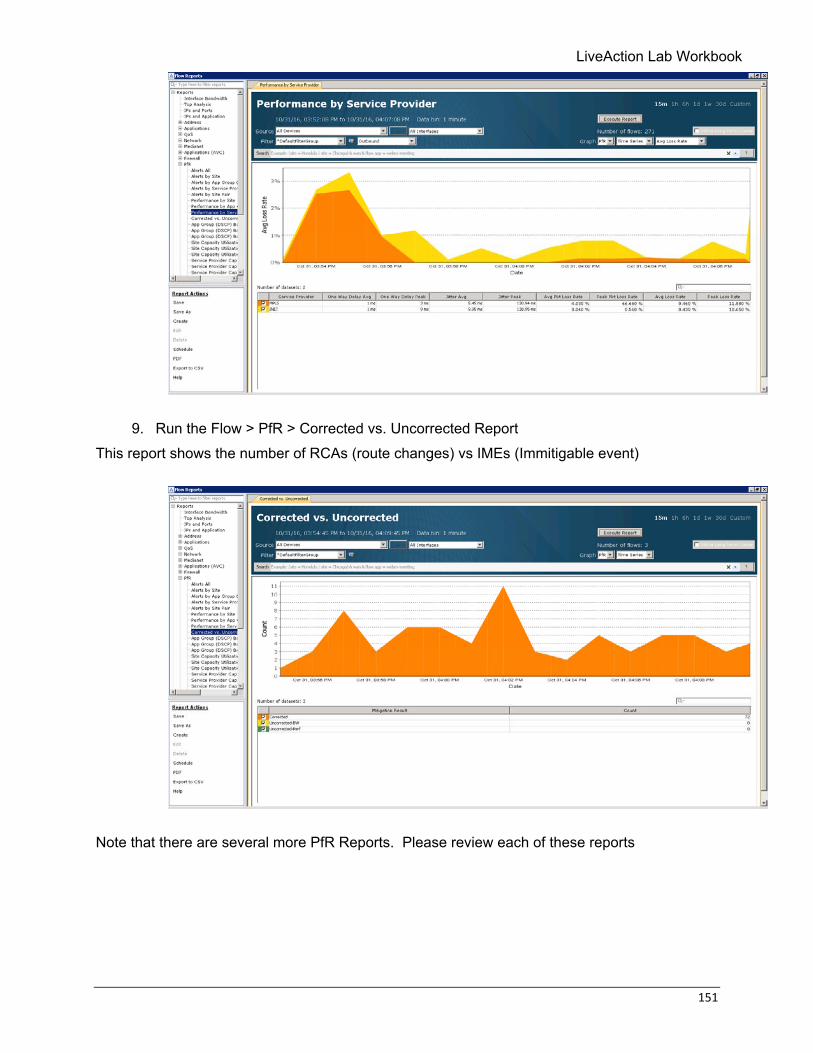
9. Run the Flow > PfR > Corrected vs. Uncorrected Report This report shows the number of RCAs (route changes) vs IMEs (Immitigable event)
Note that there are several more PfR Reports. Please review each of these reports
152 © Copyright 2018, LiveAction, Inc.
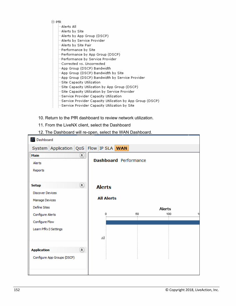
10. Return to the PfR dashboard to review network utilization. 11. From the LiveNX client, select the Dashboard 12. The Dashboard will re-open, select the WAN Dashboard.
LiveAction Lab Workbook
153
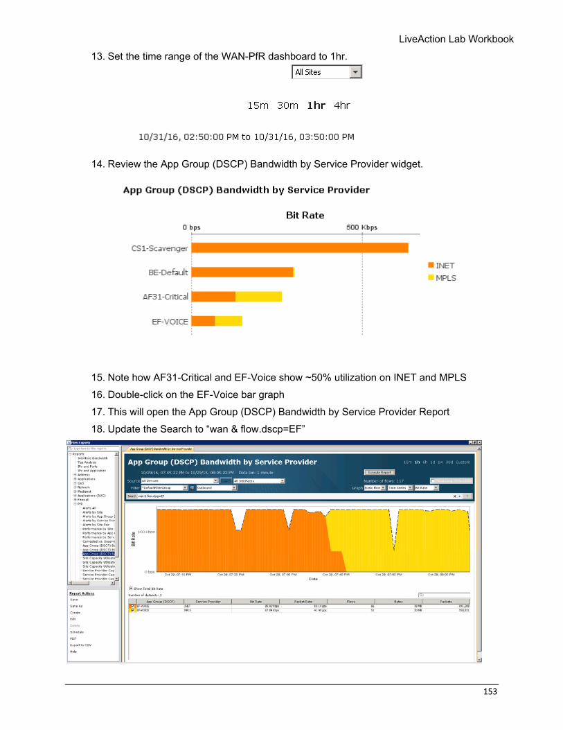
13. Set the time range of the WAN-PfR dashboard to 1hr.
14. Review the App Group (DSCP) Bandwidth by Service Provider widget.
15. Note how AF31-Critical and EF-Voice show ~50% utilization on INET and MPLS 16. Double-click on the EF-Voice bar graph 17. This will open the App Group (DSCP) Bandwidth by Service Provider Report 18. Update the Search to “wan & flow.dscp=EF”
154 © Copyright 2018, LiveAction, Inc.
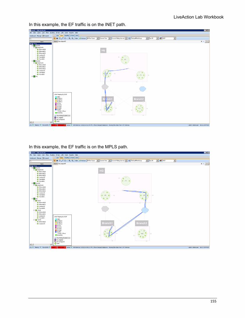
Note the time when the bandwidth graph changes colours. This shows when any PfR route changes have occurred. We will use the time in the next step.
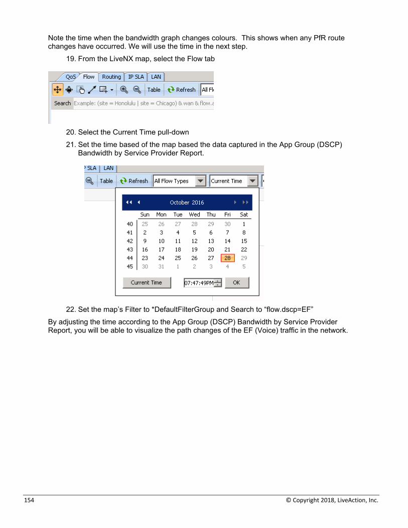
19. From the LiveNX map, select the Flow tab
20. Select the Current Time pull-down 21. Set the time based of the map based the data captured in the App Group (DSCP)
Bandwidth by Service Provider Report.
22. Set the map’s Filter to *DefaultFilterGroup and Search to “flow.dscp=EF”
By adjusting the time according to the App Group (DSCP) Bandwidth by Service Provider Report, you will be able to visualize the path changes of the EF (Voice) traffic in the network.
LiveAction Lab Workbook
155
In this example, the EF traffic is on the INET path.
In this example, the EF traffic is on the MPLS path.

156 © Copyright 2018, LiveAction, Inc.
Lab A: Appendix
LiveAction Lab Workbook
157
Lab A.1: Add Initial Device Step 2 – Add Devices into LiveAction Adding devices into LiveAction and managing them properly is very important to the overall usability of LiveAction itself.
• Your task in this section will be to add 3 devices into LiveAction, managing the correct interfaces and configuring NetFlow on the devices.
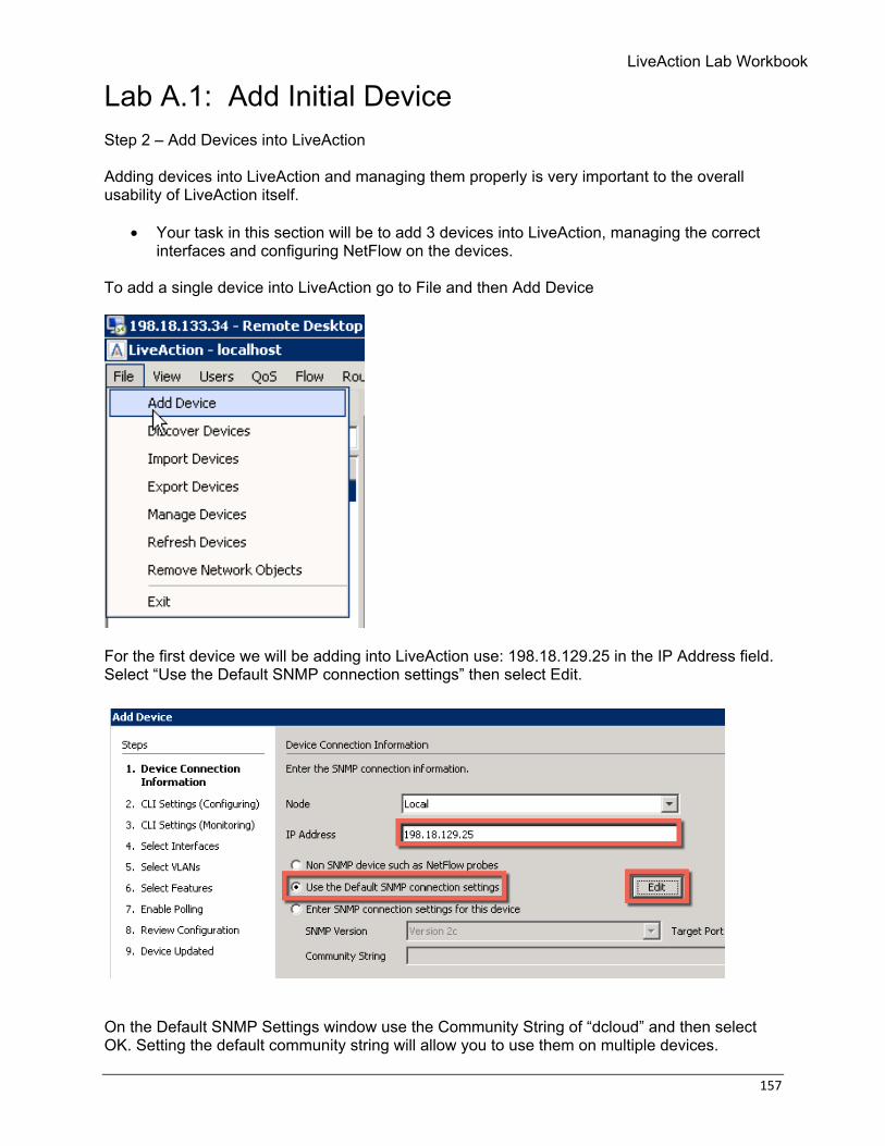
To add a single device into LiveAction go to File and then Add Device
For the first device we will be adding into LiveAction use: 198.18.129.25 in the IP Address field. Select “Use the Default SNMP connection settings” then select Edit.
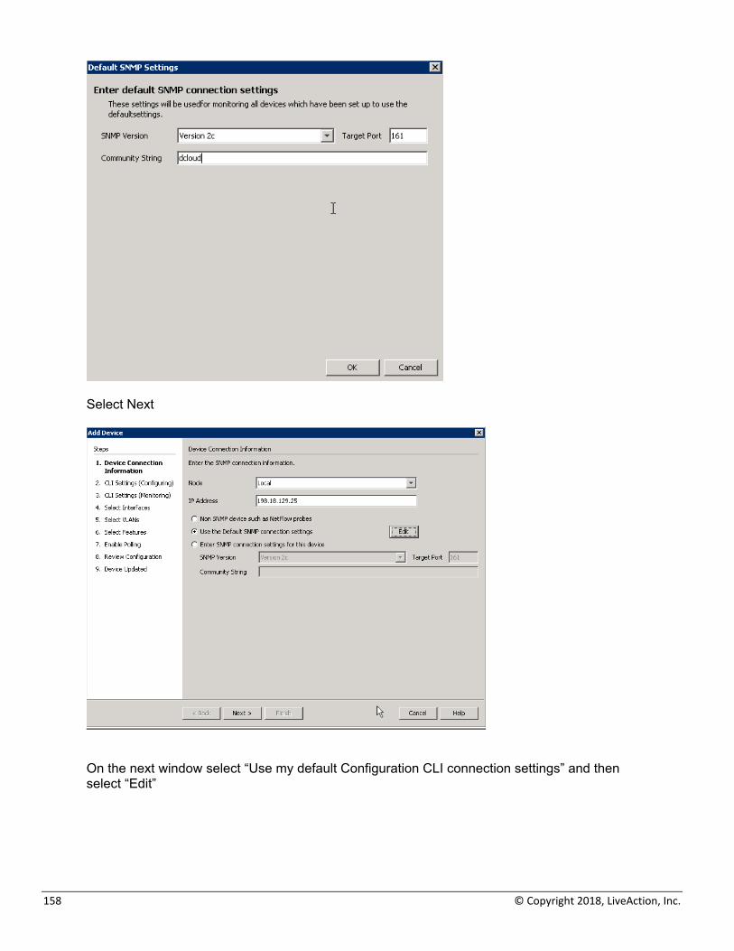
On the Default SNMP Settings window use the Community String of “dcloud” and then select OK. Setting the default community string will allow you to use them on multiple devices.
158 © Copyright 2018, LiveAction, Inc.
Select Next
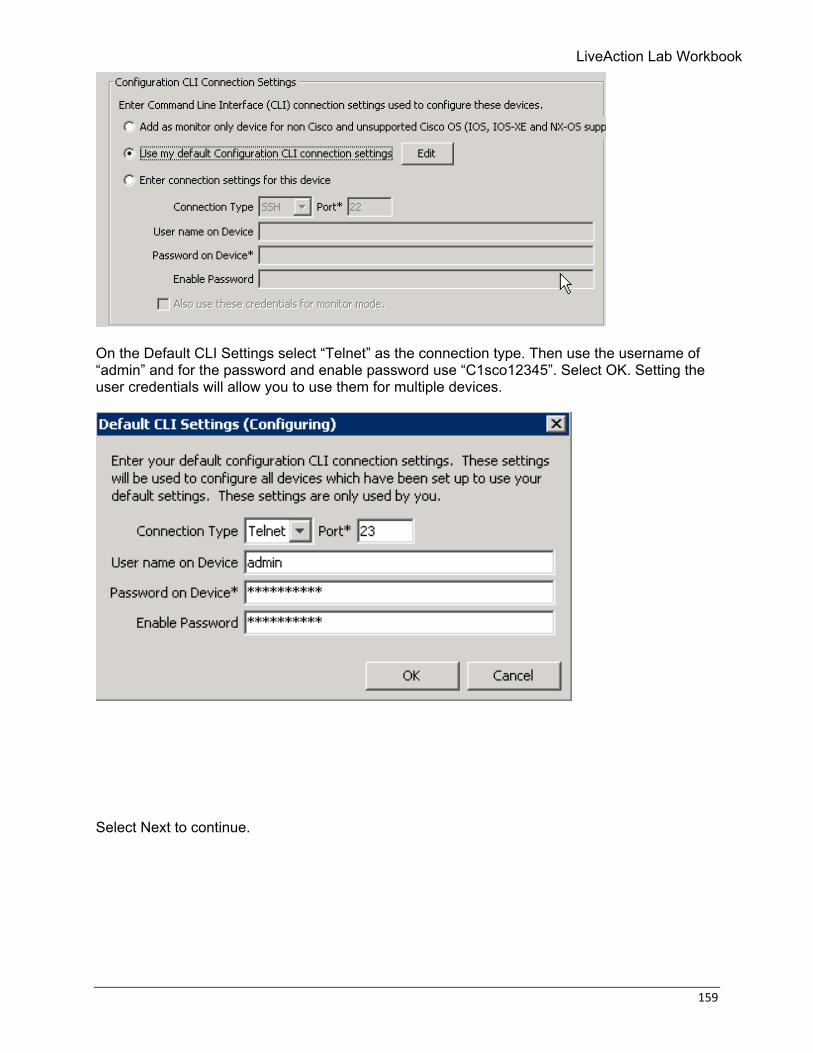
On the next window select “Use my default Configuration CLI connection settings” and then select “Edit”
LiveAction Lab Workbook
159
On the Default CLI Settings select “Telnet” as the connection type. Then use the username of “admin” and for the password and enable password use “C1sco12345”. Select OK. Setting the user credentials will allow you to use them for multiple devices.
Select Next to continue.
160 © Copyright 2018, LiveAction, Inc.
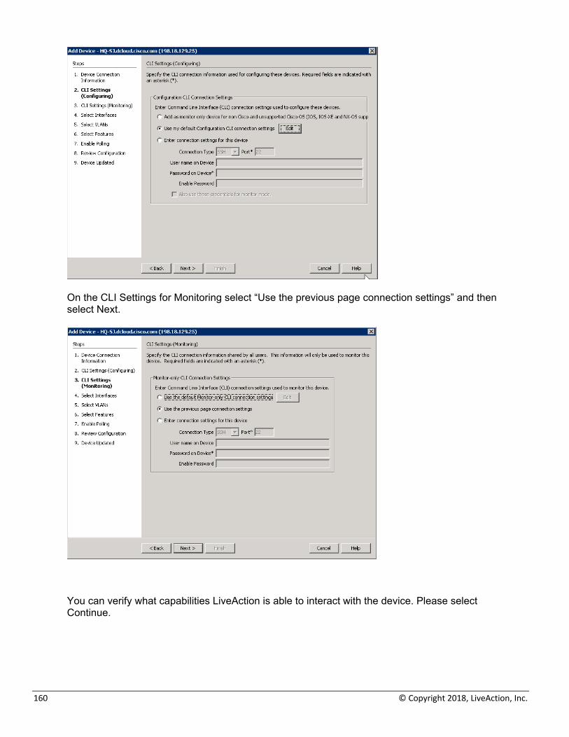
On the CLI Settings for Monitoring select “Use the previous page connection settings” and then select Next.
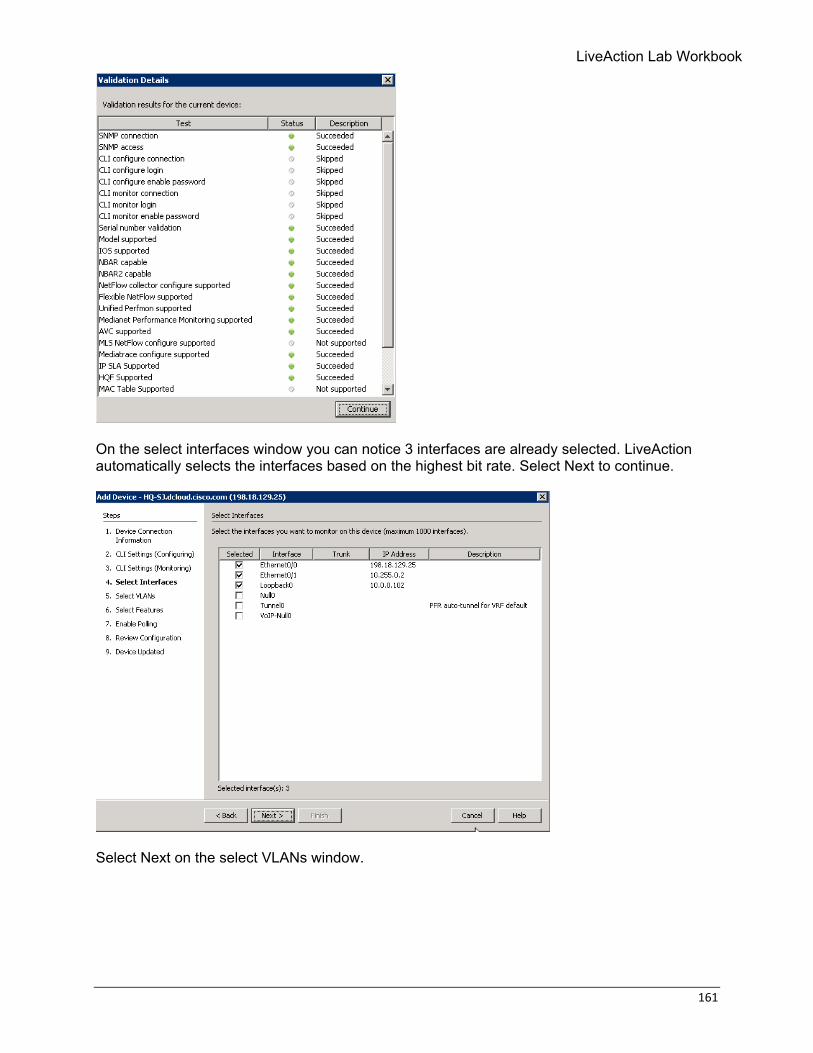
You can verify what capabilities LiveAction is able to interact with the device. Please select Continue.
LiveAction Lab Workbook
161
On the select interfaces window you can notice 3 interfaces are already selected. LiveAction automatically selects the interfaces based on the highest bit rate. Select Next to continue.
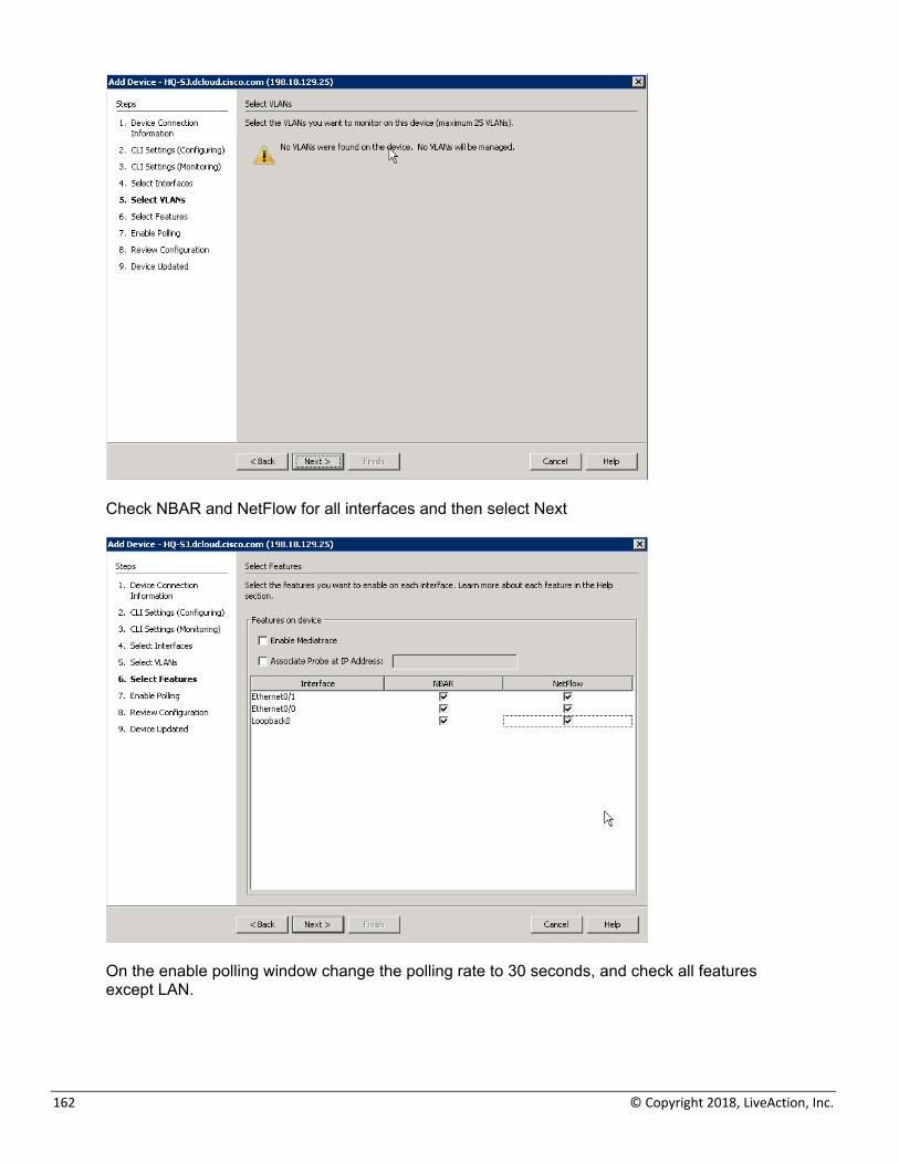
Select Next on the select VLANs window.
162 © Copyright 2018, LiveAction, Inc.
Check NBAR and NetFlow for all interfaces and then select Next
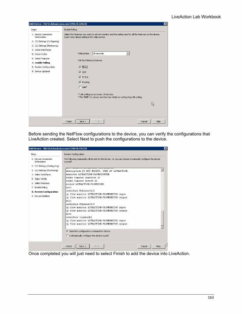
On the enable polling window change the polling rate to 30 seconds, and check all features except LAN.
LiveAction Lab Workbook
163
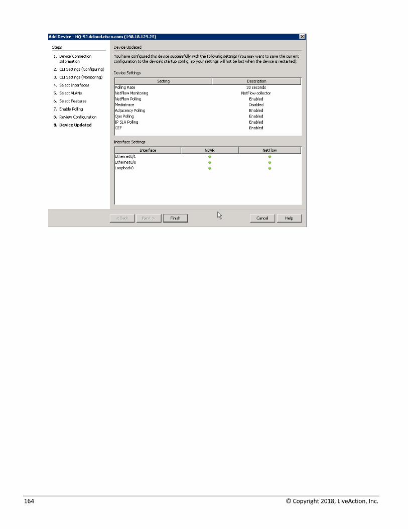
Before sending the NetFlow configurations to the device, you can verify the configurations that LiveAction created. Select Next to push the configurations to the device.
Once completed you will just need to select Finish to add the device into LiveAction.
164 © Copyright 2018, LiveAction, Inc.
LiveAction Lab Workbook
165
Lab A.2: Using Device Discovery As we discovered in the prior Lab, the LiveNX Server in your topology has had a single device pre-installed. The Appendix in this Lab Workbook details the step-by-step instructions to install the Server, Client, and adding an initial device. In the following Labs you will add additional devices to your Topology, configure those devices to send flow and SNMP data to the LiveNX Server, and discover what data your LiveNX solution is gathering. Lab Steps: Adding several devices at once is as easy as adding a single device at a time. To do this:
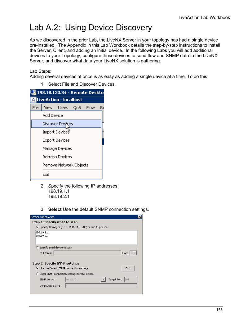
1. Select File and Discover Devices.
2. Specify the following IP addresses:
198.19.1.1 198.19.2.1
3. Select Use the default SNMP connection settings.
166 © Copyright 2018, LiveAction, Inc.
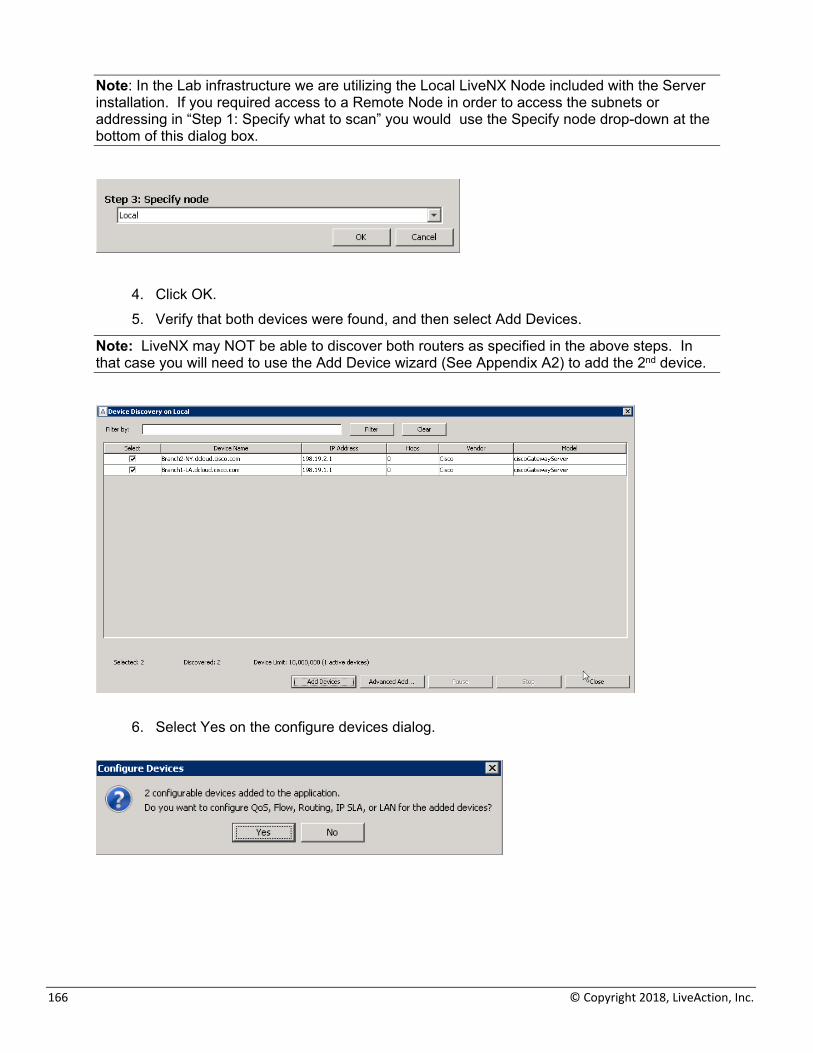
Note: In the Lab infrastructure we are utilizing the Local LiveNX Node included with the Server installation. If you required access to a Remote Node in order to access the subnets or addressing in “Step 1: Specify what to scan” you would use the Specify node drop-down at the bottom of this dialog box.
4. Click OK. 5. Verify that both devices were found, and then select Add Devices.
Note: LiveNX may NOT be able to discover both routers as specified in the above steps. In that case you will need to use the Add Device wizard (See Appendix A2) to add the 2nd device.
6. Select Yes on the configure devices dialog.
LiveAction Lab Workbook
167
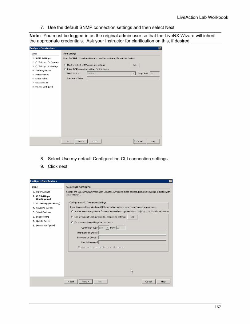
7. Use the default SNMP connection settings and then select Next
Note: You must be logged-in as the original admin user so that the LiveNX Wizard will inherit the appropriate credentials. Ask your Instructor for clarification on this, if desired.
8. Select Use my default Configuration CLI connection settings. 9. Click next.
168 © Copyright 2018, LiveAction, Inc.
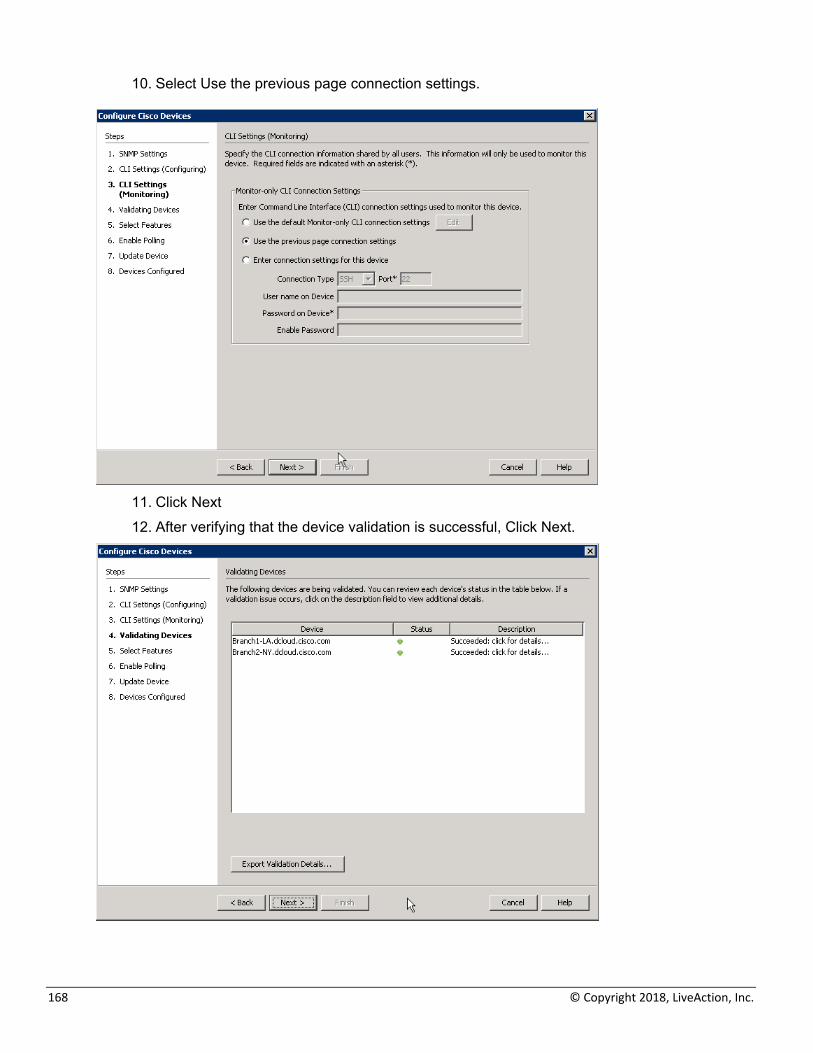
10. Select Use the previous page connection settings.
11. Click Next 12. After verifying that the device validation is successful, Click Next.
LiveAction Lab Workbook
169
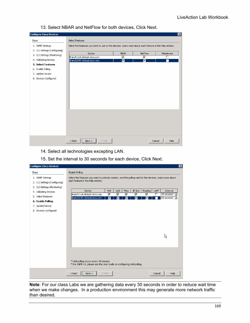
13. Select NBAR and NetFlow for both devices, Click Next.
14. Select all technologies excepting LAN. 15. Set the interval to 30 seconds for each device, Click Next.
Note: For our class Labs we are gathering data every 30 seconds in order to reduce wait time when we make changes. In a production environment this may generate more network traffic than desired.
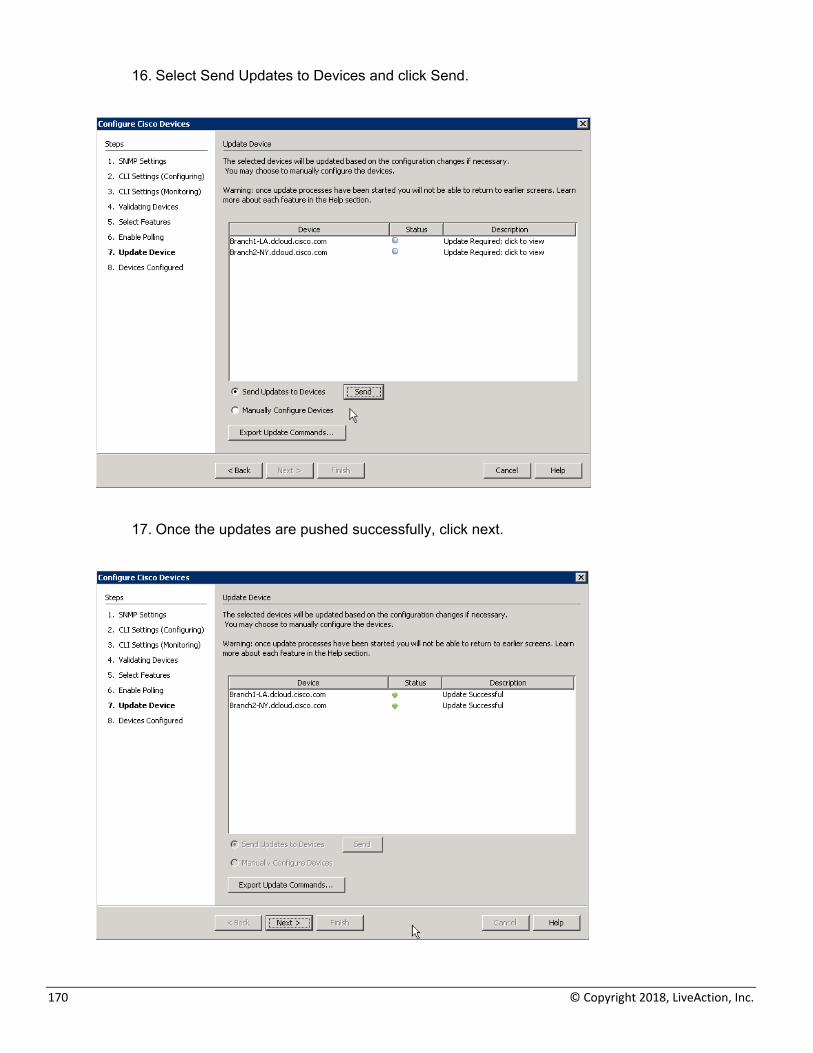
170 © Copyright 2018, LiveAction, Inc.
16. Select Send Updates to Devices and click Send.
17. Once the updates are pushed successfully, click next.
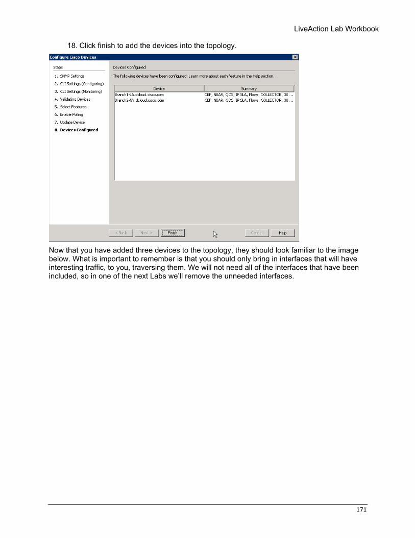
LiveAction Lab Workbook
171
18. Click finish to add the devices into the topology.
Now that you have added three devices to the topology, they should look familiar to the image below. What is important to remember is that you should only bring in interfaces that will have interesting traffic, to you, traversing them. We will not need all of the interfaces that have been included, so in one of the next Labs we’ll remove the unneeded interfaces.
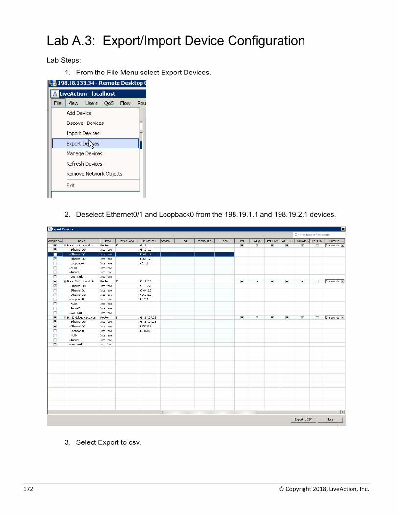
172 © Copyright 2018, LiveAction, Inc.
Lab A.3: Export/Import Device Configuration Lab Steps:
1. From the File Menu select Export Devices.
2. Deselect Ethernet0/1 and Loopback0 from the 198.19.1.1 and 198.19.2.1 devices.
3. Select Export to csv.

LiveAction Lab Workbook
173
4. On the Export window give the file a name. 5. Export the csv to the desktop, or appropriate directory.
6. Close the export devices window. 7. Select File and Import Devices.
8. Select the file you previously exported.
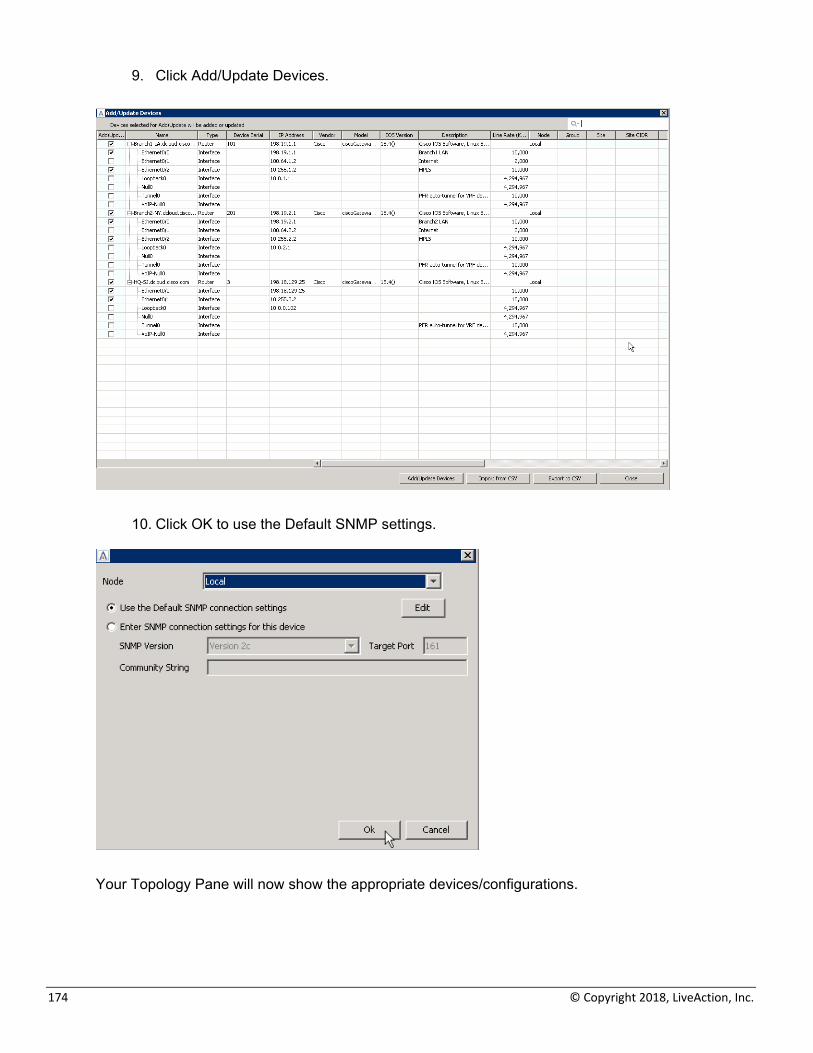
174 © Copyright 2018, LiveAction, Inc.
9. Click Add/Update Devices.
10. Click OK to use the Default SNMP settings.
Your Topology Pane will now show the appropriate devices/configurations.
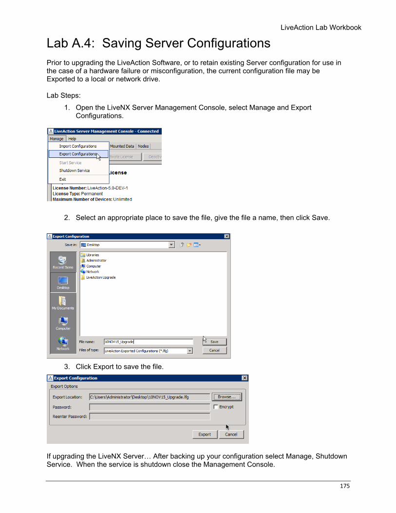
LiveAction Lab Workbook
175
Lab A.4: Saving Server Configurations Prior to upgrading the LiveAction Software, or to retain existing Server configuration for use in the case of a hardware failure or misconfiguration, the current configuration file may be Exported to a local or network drive. Lab Steps:
1. Open the LiveNX Server Management Console, select Manage and Export Configurations.
2. Select an appropriate place to save the file, give the file a name, then click Save.
3. Click Export to save the file.
If upgrading the LiveNX Server… After backing up your configuration select Manage, Shutdown Service. When the service is shutdown close the Management Console.
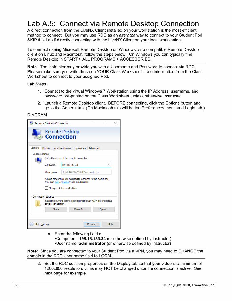
176 © Copyright 2018, LiveAction, Inc.
Lab A.5: Connect via Remote Desktop Connection A direct connection from the LiveNX Client installed on your workstation is the most efficient method to connect, But you may use RDC as an alternate way to connect to your Student Pod. SKIP this Lab if directly connecting with the LiveNX Client on your local workstation. To connect useing Microsoft Remote Desktop on Windows, or a compatible Remote Desktop client on Linux and Macintosh, follow the steps below. On Windows you can typically find Remote Desktop in START > ALL PROGRAMS > ACCESSORIES.
Note: The instructor may provide you with a Username and Password to connect via RDC. Please make sure you write these on YOUR Class Worksheet. Use information from the Class Worksheet to connect to your assigned Pod.
Lab Steps: 1. Connect to the virtual Windows 7 Workstation using the IP Address, username, and
password pre-printed on the Class Worksheet, unless otherwise instructed. 2. Launch a Remote Desktop client. BEFORE connecting, click the Options button and
go to the General tab. (On Macintosh this will be the Preferences menu and Login tab.) DIAGRAM
a. Enter the following fields:
•Computer: 198.18.133.34 (or otherwise defined by instructor) •User name: administrator (or otherwise defined by instructor)
Note: Since you are connected to your Student Pod via a VPN, you may need to CHANGE the domain in the RDC User name field to LOCAL.
3. Set the RDC session properties on the Display tab so that your video is a minimum of 1200x800 resolution… this may NOT be changed once the connection is active. See next page for example.
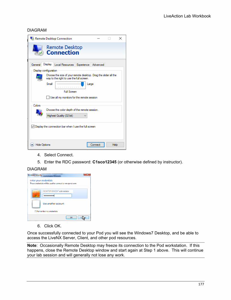
LiveAction Lab Workbook
177
DIAGRAM
4. Select Connect. 5. Enter the RDC password: C1sco12345 (or otherwise defined by instructor).
DIAGRAM
6. Click OK.
Once successfully connected to your Pod you will see the Windows7 Desktop, and be able to access the LiveNX Server, Client, and other pod resources.
Note: Occasionally Remote Desktop may freeze its connection to the Pod workstation. If this happens, close the Remote Desktop window and start again at Step 1 above. This will continue your lab session and will generally not lose any work.
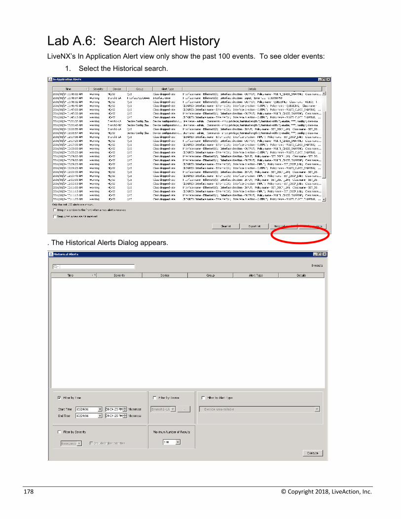
178 © Copyright 2018, LiveAction, Inc.
Lab A.6: Search Alert History LiveNX’s In Application Alert view only show the past 100 events. To see older events:
1. Select the Historical search.
. The Historical Alerts Dialog appears.
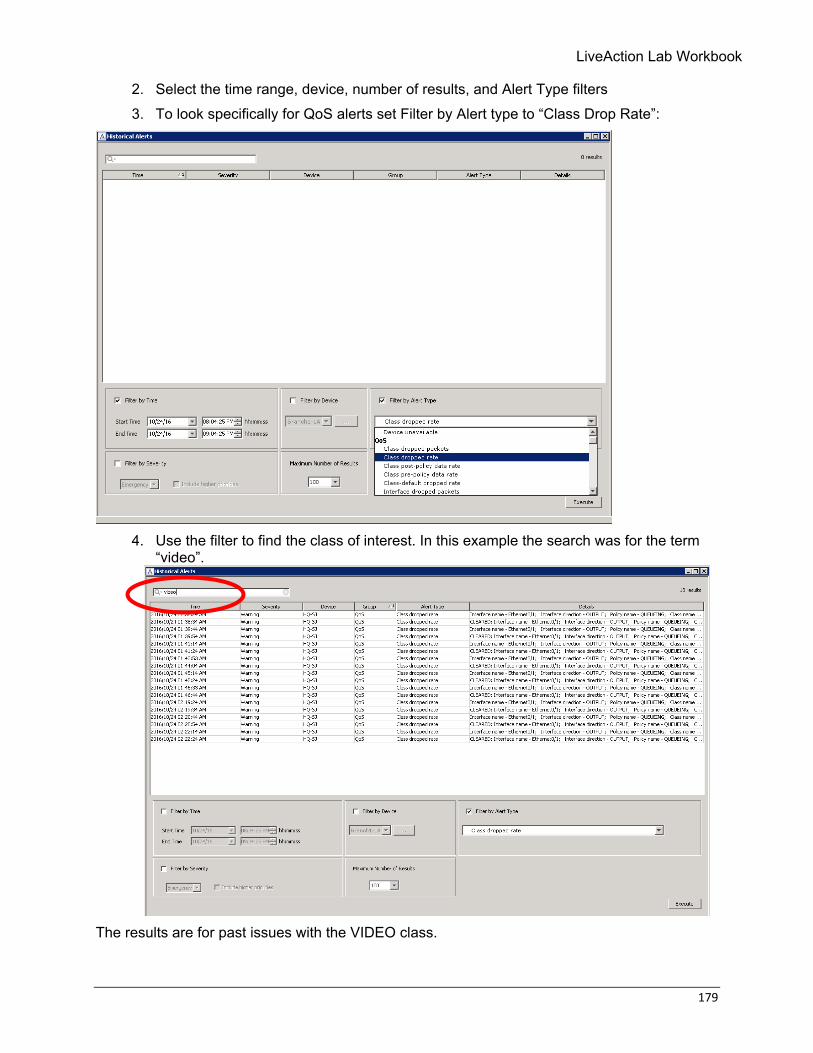
LiveAction Lab Workbook
179
2. Select the time range, device, number of results, and Alert Type filters 3. To look specifically for QoS alerts set Filter by Alert type to “Class Drop Rate”:
4. Use the filter to find the class of interest. In this example the search was for the term
“video”.
The results are for past issues with the VIDEO class.