Embed Size (px)
Citation preview
HAL Id: hal-00505952https://hal.archives-ouvertes.fr/hal-00505952
Submitted on 26 Jul 2010
HAL is a multi-disciplinary open accessarchive for the deposit and dissemination of sci-entific research documents, whether they are pub-lished or not. The documents may come fromteaching and research institutions in France orabroad, or from public or private research centers.
L’archive ouverte pluridisciplinaire HAL, estdestinée au dépôt et à la diffusion de documentsscientifiques de niveau recherche, publiés ou non,émanant des établissements d’enseignement et derecherche français ou étrangers, des laboratoirespublics ou privés.
Liver injuries in frontal crash situations: A couplednumerical-experimental approach
Pj Arnoux, T. Serre, N. Cheynel, L. Thollon, M. Behr, P. Baque, C. Brunet
To cite this version:Pj Arnoux, T. Serre, N. Cheynel, L. Thollon, M. Behr, et al.. Liver injuries in frontal crash situations:A coupled numerical-experimental approach. Computer Methods in Biomechanics and BiomedicalEngineering, Taylor & Francis, 2008, vol11,n2, p189-203. �hal-00505952�
Liver injuries in frontal crash situations A coupled numerical – experimental approach
P.J. ARNOUX1, T. SERRE1, N. CHEYNEL2, L. THOLLON1, M. BEHR1, P. BAQUE1, C. BRUNET1, 3.
1 Laboratoire de Biomécanique Appliquée, UMRT 24 Faculté de Médecine - INRETS, Université de la Méditerranée, Marseille, France.
2 Service de chirurgie digestive, thoracique et cancérologique, C.H.U. de Dijon, hôpital du Bocage - 2, Bd. Maréchal de Lattre de Tassigny – BP 77908 – 21079 Dijon cedex.
3 Service de Chirurgie générale, digestive et endocrinienne - hôpital Nord, chemin des Bourrelly, 13915, Marseille
Corresponding author: [email protected]
Abstract
From clinical knowledge, it has been established that hepatic traumas frequently lead to
lethal injuries. In frontal or lateral crash situations, these injuries can be induced by pure
deceleration effects or blunt trauma due to belt or steering wheel impact. Concerning the
liver under frontal decelerations, how could one investigate organ behaviour leading to
the injury mechanisms? This work couples experimental organ decelerations
measurements (with 19 tests on cadaver trunks) and finite element simulation, provides a
first analysis of the liver behaviour within the abdomen. It shows the influence of the liver
attachment system that leads to liver trauma and also torsion effects between the two
lobes of the liver. Injury mechanisms were evaluated through the four phases of the liver
kinematics under frontal impact: (1) postero-anterior translation, (2) compression and
sagittal rotation, (3) rotation in the transverse plane and (4) relaxation.
Keywords
Liver biomechanics, Finite element modelling, Cadaver experimentation, frontal
deceleration
1
INTRODUCTION
Motor vehicle crashes are responsible of a large number of serious life threatening
injuries. NHTSA estimates the number of serious crash injuries occurring each year in the
USA at 70000 Brain injuries, 4400 Neck and spinal cords injuries, 80000 chest and
abdominal injuries (heart, lungs, spleen, liver and kidneys), 18000 Hip and pelvic injuries,
35000 leg, ankle and foot injuries [1]. If the liver is not the most frequently injured organ,
its shape, its locations and consistence (composed of a high percentage of blood) can lead
to very severe traumas with high lethal risk [2]. Liver injuries might be attributed to
deceleration effects or penetrations in the abdomen in the crash direction. In most of
cases, the combination of these two mechanisms is involved. For penetrations
mechanisms, the liver is most frequently injured after a contact with car components in
front of the passenger (such as the steering assembly and the instrument panel) [3]. 2 point
restraint belts (the driver wearing only the shoulder strap) were most likely to produce
liver injuries in low severity frontal collisions when the force direction is 1 to 2 o’clock
against the vehicle main axis [4, 5]. Therefore, the impact direction could be a gravity
factor in side impact situations [4,5]. From clinical observations [2, 6-9], liver injuries
could be summarized by a laceration along the falciform ligaments leading to the
spreading of the two lobes, with a rupture risk for the right hepatic vein. At high
deceleration levels, the posterior attachments of the liver can be broken, especially the
inferior vena cava. Lastly in the case of penetration in the abdomen, a liver failure at the
hepatic median vein can be induced.
In order to identify injury mechanisms involved and to evaluate abdomen tolerance to
impact, many experimental studies were performed (on living animals and on human
cadavers). Walfisch [10], by dropping cadavers from two different heights, revealed a link
between velocity and compression force For Nusholtz [11] the velocity seems to
2
significantly affect the liver motion; above the injury threshold no correlation was found
between injury severity and velocity level. Kroell et al. [12] determined that for frontal
thoracic impacts, the normalized compression was a factor significantly related to injury
severity, and the velocity was implicated as a primary factor in the pathogenesis of impact
trauma. Using animal experimentations in side impacts, Klaus [13] underlined severe liver
injuries in 90° side impact situations. Rouhana [14] showed a correlation between injury
severity and applied compression and velocity. Viano [15] defined blunt lateral impact
corridors for various velocities (from 4.5 to 9.4 m/s) commonly used for dummy design
and showed a correlation between maximum viscous response and abdomen injury risk.
Viano [16] showed that low stiffness armrest limits the abdomen (and liver) injuries on
pigs in side impacts. Talantikite [17], performing isolated trunk side impacts, proposed a
tolerance level of 500 N for the liver and three tolerance levels for the abdomen (60mm
deflexion, 4400 N force and 1.98m/s viscosity criteria). All these studies tried to identify
injury typology, to define injury tolerance criteria and to evaluate safety systems.
In order to evaluate the abdominal injury mechanisms observed clinically (chronology of
liver deformations and kinematics regarding other abdominal structures), we used a
coupled numerical/experimental approach to simulate belted and unbelted trunk
decelerations. The results lead to evaluating global liver behaviour in the abdominal
cavity and the possible induced injuries. If experimental tests alone were not sufficient to
provide a good estimation of the liver behaviour and kinematics, by coupling finite
element simulation, it was then possible to identify a four phase behaviour of the liver
kinematics which could explain the hepatic veins avulsions encountered in real life
impacts.
In this paper, an overview of the model definition up to existing validation data is
proposed. Then experimental tests performed in the laboratory are reported and simulated
3
in order to evaluate our model capability and improve our knowledge on liver behaviour
in such dynamic loading cases.
MATERIALS and METHODS
Overview of HUMOS model, design and validation
General Model Overview: The HUMOS1 model [18] is the result of an EU BRITE-
EURAM project which aimed at developing a 3D finite element model of the human body
in driving position and validating using test results in the vehicle crash environment. The
first step of the model development process was to select a cadaver close to the 50th
percentile European male. The subject was then placed in a car cockpit in driving position
and frozen for slicing purposes [19, 20]. Serial sections were performed and digitized in
order to produce anatomical data. Organ, muscle and bone contours were identified by
anatomists on each section. The contours were processed to create a 3D reconstruction of
the human body. The model is made of approximately 50,000 elements and includes
descriptions of all compact and spongious bones, ligaments, muscles and tendons, skin,
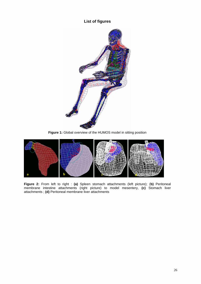
abdominal and thoracic viscera, and intracranial contents (cf. figure 1).
‘[Insert Figure 1]’
Physical properties of the different tissues in the body were based on literature data [21-
29], and specific experiments were conducted for the HUMOS project. In the model,
trabecular and cortical bones were assumed as elastoplastic materials. Soft tissues such as
ligaments, tendons, passive muscles, and organs were considered as viscoelastic or elastic
materials. Finally, skin and cartilage were assumed to be elastic. Modelling of muscles
was performed in two steps. First, volumetric shapes of muscles were generated using
solid elements in order to take into account the damping mechanical properties of passive
muscles at impact. Secondly, the lines of action for each muscle were modelled as
springs. Therefore, a careful attention was paid to the interface definition between each
4
component of the model. Interfaces were modelled to provide for both adhesive properties
and sliding friction between moving parts.
Trunk modelling: In the abdomen, the stomach is a continuous mesh including
duodenum and pancreas, leading to a peritoneal-retroperitoneal separation which does not
strictly correspond to reality. The liver, spleen and kidneys are described as separated
entities. Lastly the intestines (small intestine & colon) were gathered in one same part
with a continuous mesh and called “Abdominal bag”. For the thorax, heart and lungs were
modelled and linked together with a continuous connective mesh to fill in remaining gaps
in the model. These components were modelled using typical brick elements with
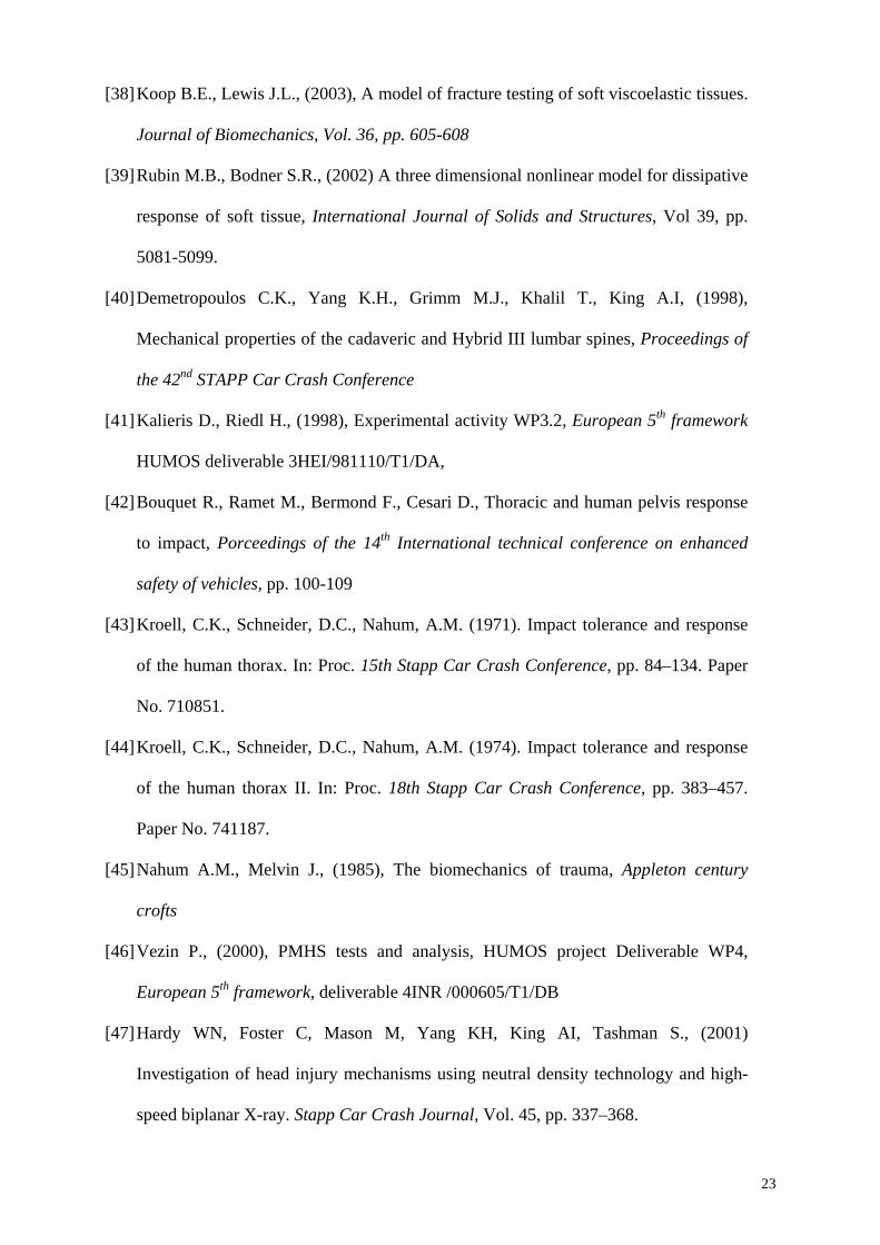
Boltzmann or Kelvin Voigt viscoelastic laws [48, 49]. Hard tissues i.e. pelvis, sacrum,
spine, clavicle, sternum, scapula and rib bones were described as shell elements for
compact bones and solid elements for spongious bones and modelled with an Elastoplastic
Johnson cook behaviour law. Ribcage and pelvis cartilage were modelled using elastic
shell and solid elements. The “flesh” tissue -skin (shell), muscles (solids) and connective
flesh (solids used to fill gap in the model)- was assumed to follow a viscoelastic
(Boltzmann & Pointing Thomson) behaviour law. An overview of the main parameters
for internal organs and bone components is provided in tables 1, 2 and 3.
‘[Insert Table 1, 2 & 3 about here]’
As it was difficult to investigate tissues tribology, according to anatomical considerations,
we assumed two different situations in order to describe tissue interactions: Adhesive and
sliding properties. These situations can be obtained through three modelling choices:
- The continuous mesh used for stomach, abdominal bag or thorax segment was used to
allow interactions between the different components,
- A set of springs (with a 60 to 100N/mm stiffness) was also used for organ attachments
(modelling organ ligaments) or to describe adhesive properties between organs and
5
membranes. It mainly concerned the peritoneal membrane to intestine and liver to spleen
attachments (see illustration on figure 2).
- Typical Coulomb friction interfaces with frictional coefficient of 0.1 were used to ensure
contact or adhesive properties between the different components of the abdomen and
thorax segment (more than 120 interfaces were used)). Note that specific tied interfaces
(which consist in kinematics conditions between the two objects) were used to complete
attachment of the different organs (see illustration figure 2), especially between intestine
and peritoneal membranes, stomach and liver, and liver and peritoneal membranes.
‘[Insert Figure 2 about here]’
Validation of the HUMOS model was performed in incremental steps. First, material
properties of isolated elements (i.e. cortical bone, trabecular bone, ligament, functional
spinal unit, etc.) were evaluated individually on the basis of traction, compression,
shearing and bending tests. As behaviour law required parameters which didn’t match
with available experimental data, optimisation procedures were performed on the
difference between experimental and simulated recorded data (usually stress versus strain)
in order to fit these parameters using NLPQL methods on Radioss Dss optimisation tool
[51]. Next, validation was performed on sub-segments (i.e. head-neck, thorax, upper
extremity, etc.) by comparison to experimental data during simulated frontal, lateral and
oblique impacts. Finally, the whole model was validated with a sled test performed for the
HUMOS project. For the specific case of liver, the model parameters were optimized on
the base of quasi-static compression tests [35, 50] and reported in table 3. An overview of
the trunk model validation is reported in table 3. Note that more details about model
definition and validation procedure were reported in references [18; 25; 26].
‘[Insert Table 4 about here]’
Concerning the abdomen, the validation procedure (dealing with liver injuries) focused on
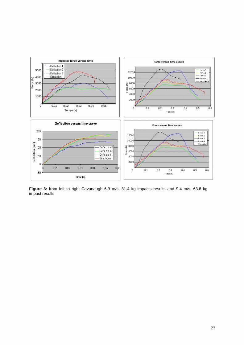
abdominal impact tests reported by Viano [15] and Cavanaugh [30]. In Cavanaugh’s
6
study, subjects were seated with their back set vertical, arms along the body, and were
suspended by a cable (passing under the armpits) which was released just prior to impact.
The linear impactor is horizontal, with its axis centred on L3. The impacting device is a
25 mm wide and 400 mm long cylinder (simulating a steering wheel ring). Two sets of
experiments were performed with different velocities and impactor masses ([6.9 m/s, 31.4
kg] and [9.4 m/s, 63.6 kg]). For these tests the validation was computed on force and
deflexion on the impactor (see illustration on figure 3). Oblique Impact test are based on
Viano’s experimental study [15]. For these tests, the impacting surface is circular, 150
mm in diameter, with a 23.4 kg mass and an initial velocities of 4.8, 6.8 and 9.4 m/s. The
impact is centred on the thorax with a 30° angle. The impact is delivered at the level of
the xiphoid process, 15 cm under the centre of the sternum and validation performed on
force versus time and deflexion versus time curves (see figure 4).
‘[Insert Figure 3&4 about here]’
Experimental Trunk deceleration tests. In order to investigate liver behaviour in the
abdomen during a frontal deceleration, experimental free-fall tests using cadaver’s trunks
were performed. Trunks from 6 human cadavers (59, 69, 78, 85-year-old men and 2
women aged 81 and 82) were tested. The cadavers (obtained from the pathology
department of the University of Mediterranée – Medicine Faculty of Marseilles) were
treated with Winckler solution [31] to ensure proper preservation of soft tissues and then
held at +3°C until testing. Prior to testing, the trunks were thawed to room temperature,
sensors were inserted; and X-rays performed to check bone integrity and sensors
orientations. The trunk was dissected by removing upper limbs, head and neck segment,
lower limbs, the greater pelvis and the lower abdomen viscera. On the abdominal segment
only the colon was kept. From an anatomical point of view, the liver attachments are
active on its proximal and rear parts. Therefore, greater pelvis and lower abdominal
7
viscera were removed as we considered they do not have a mechanical contribution to the
behaviour of the whole structure. Trunks were instrumented using 2D and 3D ENTRAN
accelerometers (±25g acquisition range, recorded at 10Khz and sampled at 1kHz with a
specific conditioning in order to keep water tightness during experiments). 3D
accelerometers were fixed on the anterior part of the manubrium sternum and 2D
accelerometers on the anterior face of the L1 lumbar spine. Due to the size of sensors it
was only possible to use 2D sensors on the vena cava and the left and right lobes of the
liver. The liver accelerometers were inserted at the geometrical centre of each lobe using a
surgical technique with an insertion direction which was initially perpendicular to the
loading axes. The vena cava accelerometer was inserted and then fixed in the vessel using
an injected silicone gel. All sensors were inserted in order to have one orientation in the
direction of loading and the second one in the lateral medial direction. In order to validate
the sensors orientation, during the acceleration phase of the trunk (prior to impact), the
acceleration recorded on sensors was compared to the theoretical 1G acceleration (free
fall). In order to avoid creating air-filled voids in the abdominal cavity, once sensors were
inserted, the abdominal cavity was closed, sutured and then packed in an hermetic bag.
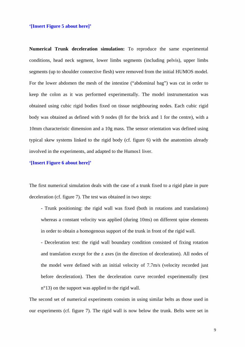
The trunk was then belted to the free fall system in order to have the anatomical anterior
posterior axes in the impact direction. The free fall system is a vertical mobile which can
be released at heights varying from 1 to 4m (cf. figure 5). At the end of the free fall, a
braking system stops the mobile set on the same distance whatever the initial velocity.
Each trunk was tested with three different sets of velocities (~4m/s, ~6m/s and ~8m/s).
All tests were filmed with high-speed video cameras (1000 frames/second) in the frontal
view. Accelerations were recorded with a 10 kHz sample frequency. For each test the
trunk was belted with a car lateral belt system at the lower sternum and the umbilical
regions. One additional test was performed by replacing the belt with a rigid plate. A total
of 19 tests were performed.
8
‘[Insert Figure 5 about here]’
Numerical Trunk deceleration simulation: To reproduce the same experimental
conditions, head neck segment, lower limbs segments (including pelvis), upper limbs
segments (up to shoulder connective flesh) were removed from the initial HUMOS model.
For the lower abdomen the mesh of the intestine (“abdominal bag”) was cut in order to
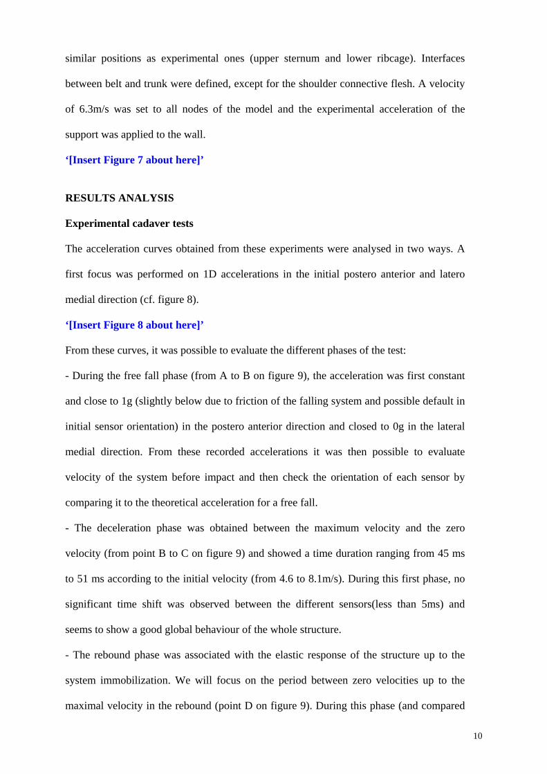
keep the colon as it was performed experimentally. The model instrumentation was
obtained using cubic rigid bodies fixed on tissue neighbouring nodes. Each cubic rigid
body was obtained as defined with 9 nodes (8 for the brick and 1 for the centre), with a
10mm characteristic dimension and a 10g mass. The sensor orientation was defined using
typical skew systems linked to the rigid body (cf. figure 6) with the anatomists already
involved in the experiments, and adapted to the Humos1 liver.
‘[Insert Figure 6 about here]’
The first numerical simulation deals with the case of a trunk fixed to a rigid plate in pure
deceleration (cf. figure 7). The test was obtained in two steps:
- Trunk positioning: the rigid wall was fixed (both in rotations and translations)
whereas a constant velocity was applied (during 10ms) on different spine elements
in order to obtain a homogenous support of the trunk in front of the rigid wall.
- Deceleration test: the rigid wall boundary condition consisted of fixing rotation
and translation except for the z axes (in the direction of deceleration). All nodes of
the model were defined with an initial velocity of 7.7m/s (velocity recorded just
before deceleration). Then the deceleration curve recorded experimentally (test
n°13) on the support was applied to the rigid wall.
The second set of numerical experiments consists in using similar belts as those used in
our experiments (cf. figure 7). The rigid wall is now below the trunk. Belts were set in
9
similar positions as experimental ones (upper sternum and lower ribcage). Interfaces
between belt and trunk were defined, except for the shoulder connective flesh. A velocity
of 6.3m/s was set to all nodes of the model and the experimental acceleration of the
support was applied to the wall.
‘[Insert Figure 7 about here]’
RESULTS ANALYSIS
Experimental cadaver tests
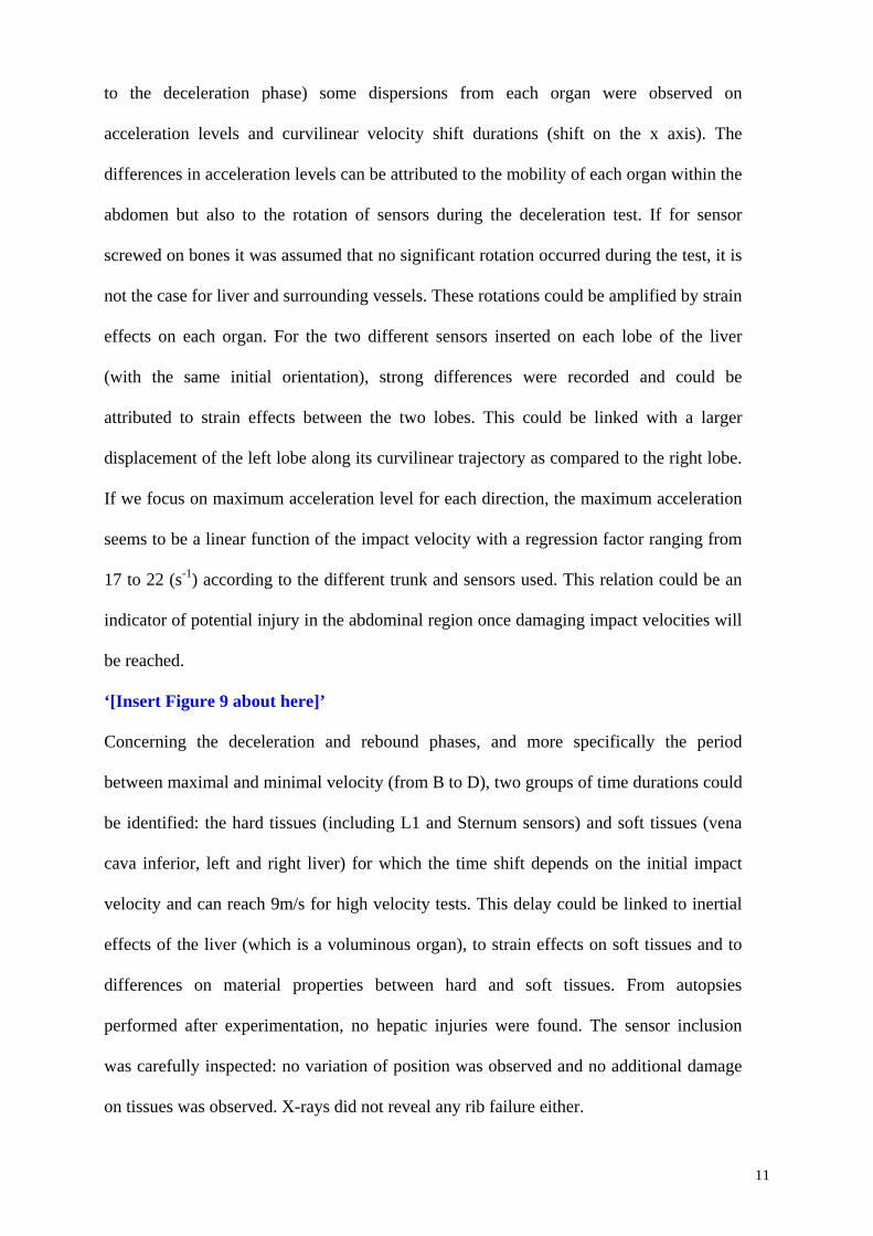
The acceleration curves obtained from these experiments were analysed in two ways. A
first focus was performed on 1D accelerations in the initial postero anterior and latero
medial direction (cf. figure 8).
‘[Insert Figure 8 about here]’
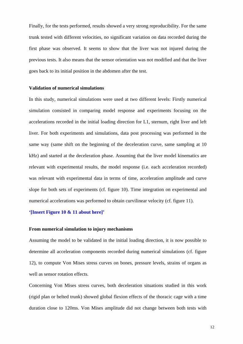
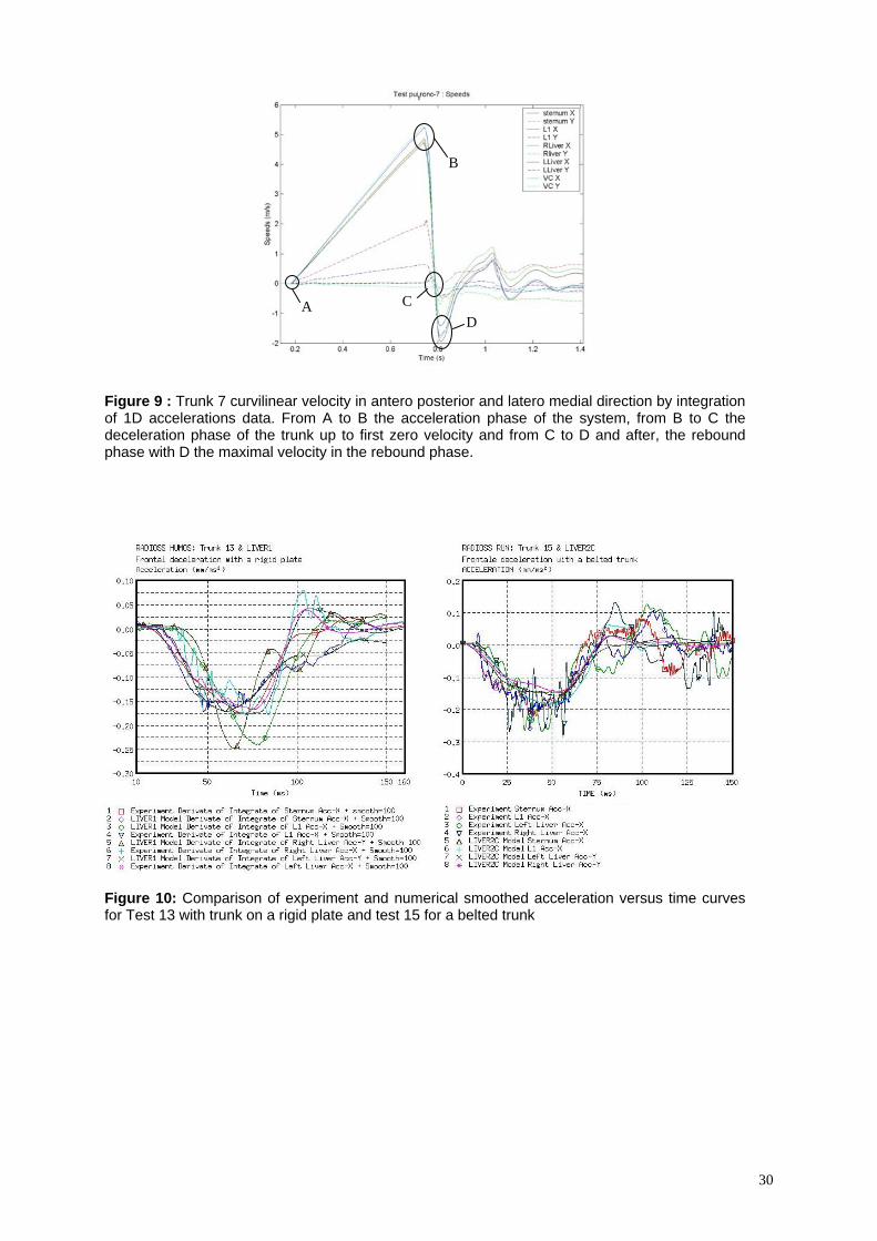
From these curves, it was possible to evaluate the different phases of the test:
- During the free fall phase (from A to B on figure 9), the acceleration was first constant
and close to 1g (slightly below due to friction of the falling system and possible default in
initial sensor orientation) in the postero anterior direction and closed to 0g in the lateral
medial direction. From these recorded accelerations it was then possible to evaluate
velocity of the system before impact and then check the orientation of each sensor by
comparing it to the theoretical acceleration for a free fall.
- The deceleration phase was obtained between the maximum velocity and the zero
velocity (from point B to C on figure 9) and showed a time duration ranging from 45 ms
to 51 ms according to the initial velocity (from 4.6 to 8.1m/s). During this first phase, no
significant time shift was observed between the different sensors(less than 5ms) and
seems to show a good global behaviour of the whole structure.
- The rebound phase was associated with the elastic response of the structure up to the
system immobilization. We will focus on the period between zero velocities up to the
maximal velocity in the rebound (point D on figure 9). During this phase (and compared
10
to the deceleration phase) some dispersions from each organ were observed on
acceleration levels and curvilinear velocity shift durations (shift on the x axis). The
differences in acceleration levels can be attributed to the mobility of each organ within the
abdomen but also to the rotation of sensors during the deceleration test. If for sensor
screwed on bones it was assumed that no significant rotation occurred during the test, it is
not the case for liver and surrounding vessels. These rotations could be amplified by strain
effects on each organ. For the two different sensors inserted on each lobe of the liver
(with the same initial orientation), strong differences were recorded and could be
attributed to strain effects between the two lobes. This could be linked with a larger
displacement of the left lobe along its curvilinear trajectory as compared to the right lobe.
If we focus on maximum acceleration level for each direction, the maximum acceleration
seems to be a linear function of the impact velocity with a regression factor ranging from
17 to 22 (s-1) according to the different trunk and sensors used. This relation could be an
indicator of potential injury in the abdominal region once damaging impact velocities will
be reached.
‘[Insert Figure 9 about here]’
Concerning the deceleration and rebound phases, and more specifically the period
between maximal and minimal velocity (from B to D), two groups of time durations could
be identified: the hard tissues (including L1 and Sternum sensors) and soft tissues (vena
cava inferior, left and right liver) for which the time shift depends on the initial impact
velocity and can reach 9m/s for high velocity tests. This delay could be linked to inertial
effects of the liver (which is a voluminous organ), to strain effects on soft tissues and to
differences on material properties between hard and soft tissues. From autopsies
performed after experimentation, no hepatic injuries were found. The sensor inclusion
was carefully inspected: no variation of position was observed and no additional damage
on tissues was observed. X-rays did not reveal any rib failure either.
11
Finally, for the tests performed, results showed a very strong reproducibility. For the same
trunk tested with different velocities, no significant variation on data recorded during the
first phase was observed. It seems to show that the liver was not injured during the
previous tests. It also means that the sensor orientation was not modified and that the liver
goes back to its initial position in the abdomen after the test.
Validation of numerical simulations
In this study, numerical simulations were used at two different levels: Firstly numerical
simulation consisted in comparing model response and experiments focusing on the
accelerations recorded in the initial loading direction for L1, sternum, right liver and left
liver. For both experiments and simulations, data post processing was performed in the
same way (same shift on the beginning of the deceleration curve, same sampling at 10
kHz) and started at the deceleration phase. Assuming that the liver model kinematics are
relevant with experimental results, the model response (i.e. each acceleration recorded)
was relevant with experimental data in terms of time, acceleration amplitude and curve
slope for both sets of experiments (cf. figure 10). Time integration on experimental and
numerical accelerations was performed to obtain curvilinear velocity (cf. figure 11).
‘[Insert Figure 10 & 11 about here]’
From numerical simulation to injury mechanisms
Assuming the model to be validated in the initial loading direction, it is now possible to
determine all acceleration components recorded during numerical simulations (cf. figure
12), to compute Von Mises stress curves on bones, pressure levels, strains of organs as
well as sensor rotation effects.
Concerning Von Mises stress curves, both deceleration situations studied in this work
(rigid plan or belted trunk) showed global flexion effects of the thoracic cage with a time
duration close to 120ms. Von Mises amplitude did not change between both tests with
12
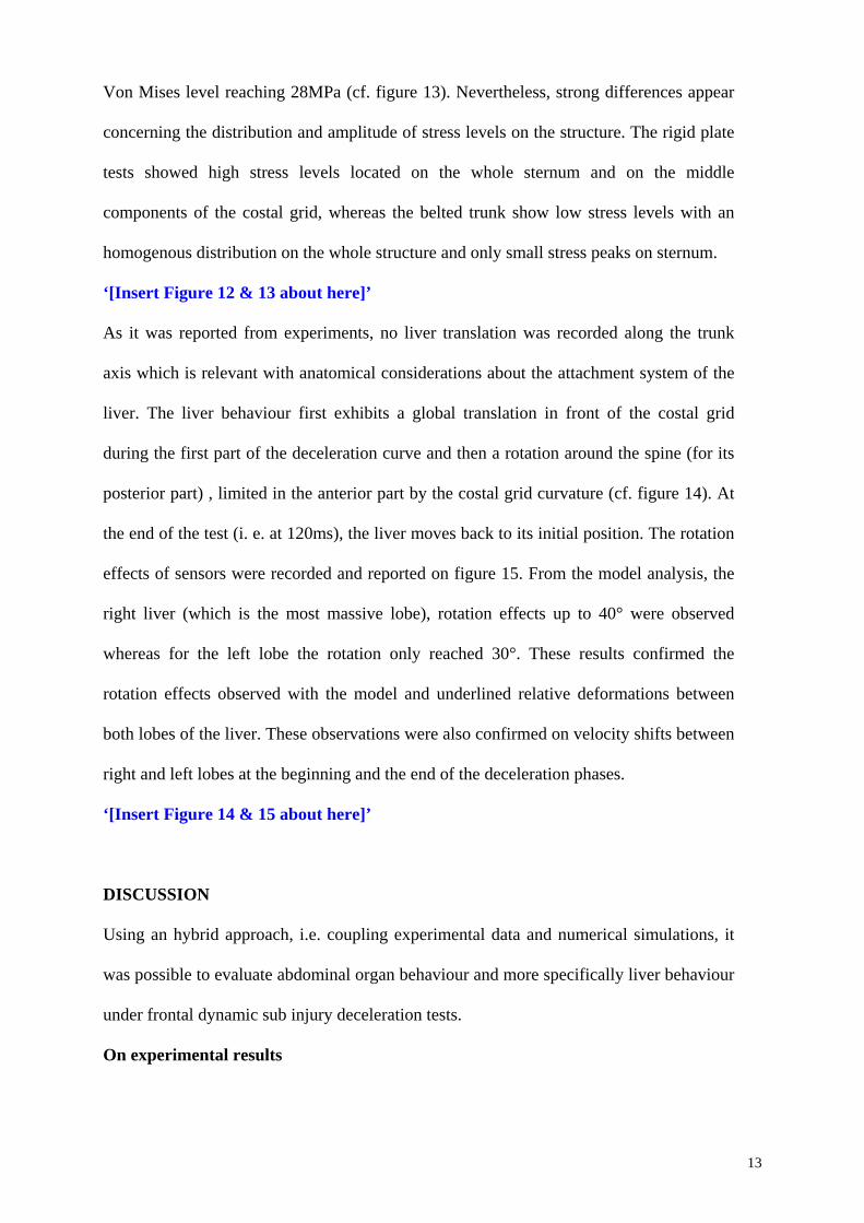
Von Mises level reaching 28MPa (cf. figure 13). Nevertheless, strong differences appear
concerning the distribution and amplitude of stress levels on the structure. The rigid plate
tests showed high stress levels located on the whole sternum and on the middle
components of the costal grid, whereas the belted trunk show low stress levels with an
homogenous distribution on the whole structure and only small stress peaks on sternum.
‘[Insert Figure 12 & 13 about here]’
As it was reported from experiments, no liver translation was recorded along the trunk
axis which is relevant with anatomical considerations about the attachment system of the
liver. The liver behaviour first exhibits a global translation in front of the costal grid
during the first part of the deceleration curve and then a rotation around the spine (for its
posterior part) , limited in the anterior part by the costal grid curvature (cf. figure 14). At
the end of the test (i. e. at 120ms), the liver moves back to its initial position. The rotation
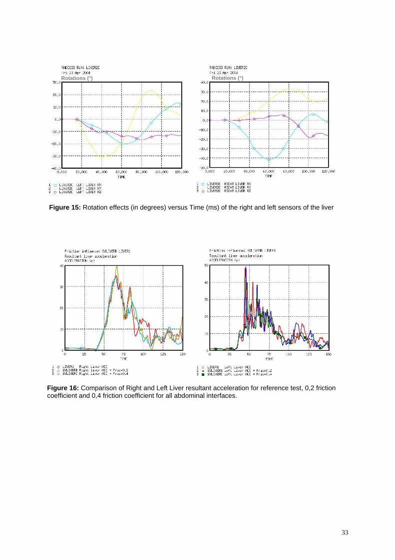
effects of sensors were recorded and reported on figure 15. From the model analysis, the
right liver (which is the most massive lobe), rotation effects up to 40° were observed
whereas for the left lobe the rotation only reached 30°. These results confirmed the
rotation effects observed with the model and underlined relative deformations between
both lobes of the liver. These observations were also confirmed on velocity shifts between
right and left lobes at the beginning and the end of the deceleration phases.
‘[Insert Figure 14 & 15 about here]’
DISCUSSION
Using an hybrid approach, i.e. coupling experimental data and numerical simulations, it
was possible to evaluate abdominal organ behaviour and more specifically liver behaviour
under frontal dynamic sub injury deceleration tests.
On experimental results
13
Experimental data on cadaver testing under dynamic loading are usually recorded by
screwing or sticking accelerometers on bones. Few attempts have been performed to
instrument soft tissue structures. This first set of experiments showed that it was possible
to perform such experimentations and open large prospects of experimentation concerning
thoracic and abdominal organ behaviour under crash situations. Even though results
should be carefully analysed and can not be directly used to postulate on injury
mechanisms or injury thresholds. They need to be coupled with numerical simulation in
order to provide a more exhaustive analysis of the problem.
The way sensors were used (set perpendicular to the loading axis and followed by silicon
inclusion) showed good efficiency and did not induce any orientation or initial position
variations, as observed in sets of experiments performed with one same instrumented
trunk. If the sensors orientation before and after each experiment was checked with
acceleration curves and X-rays measurements, some improvements should be performed
concerning the X-rays identification of initial orientation, by inserting specific markers on
the sensors. As we were concerned about avoiding tissue damage during experiments,
small-sized 2D accelerometers were used. But it limits the possibilities of analysing
experimental results. Even if the ratio between liver and sensors density is around 2.5, the
liver global mass is around 1.6Kg compared to 20g for the two 3D sensors. This point
leads us to assume that sensors inertial effects can be negligible regarding whole liver
inertial effects. Further experiments should involve small 3D sensors (and new technology
sensors [47]) in order to avoid tissue damaging (regarding liver density and water
tightness).
The results obtained show a strong reproducibility on the 19 tests performed as well for
the general curve shape as for recorded data amplitude and time durations. If these 1D and
2D accelerations can not be directly used to study the structure behaviour, these data were
strictly necessary to the model evaluation and validation. Using accelerometer data in
14
order to evaluate velocities or displacement is a very complex task for which numerical
integration can provide strong errors. Moreover, experimental data analysis was based on
the different time phases of the phenomena and then used to validate the model response.
Amplitude phenomena were only used directly on acceleration data. As experimental
results were compared to simulations, they were submitted to the same post-processing
procedure as for simulations.
The differences in terms of time duration between the different sensors during the
deceleration phase could be qualitatively analysed. These results seem to indicate two
phase behaviour: (1) global kinematics of the internal organs during the first part of the
trunk deceleration, (2) increasing time shift (with impact velocity) between hard tissues
(L1 and sternum) and soft tissues structures (left lobe, right lobe and vena cava inferior).
These results show significant differences concerning kinematics of the liver itself and its
surrounding structures. Therefore, with a high velocity level, differences in time duration
(up to 6ms) appear between L1, right and left liver. This dispersion is significant and may
be considered as an indication of the global kinematics of the liver regarding L1, but also
strain effects between left and right liver lobes. It also shows the contribution of the vena
cava inferior in the mechanical attachment of the structure. Lastly, it seems that the liver
morphology (i.e. anterior spreading and posterior spreading) could have an influence on
results, but require more experiments to be discussed in detail.
About numerical simulation: model evaluation and hybrid analysis
The Humos model put in the same conditions as the experiments show relevant results
(assuming the sensor kinematics are relevant with experimental ones) with those obtained
for both types of experiments (belted trunk and trunk fixed on a rigid plate). Humos being
in seating position, its spine curvature is different from those of experiments, due to
standing position of the PMHS. Consequently the model quality response could be
improved by setting the model in standing position prior to the test. Regarding model
15
sensitivity, it has been shown that model mass, model geometry, behaviour laws and
obviously mesh size can induce significative variations in the model responses especially
when model is used to investigate high speed loading and failure domain [18, 25, and 26].
As in this study, we focus on global liver behaviour and kinematics; the question of model
sensitivity was estimated regarding model behaviour. Complementary tests were
performed to investigate friction coefficient influence on liver related interfaces by setting
all friction coefficient to 0,2 and 0,4. The resultant acceleration exhibit some variations in
amplitude but not in phenomena described (cf. figure 16). These variations were in the
same magnitude as biological variability regarding experimental tests performed.
Consequently, they are not assumed to modify significantly model kinematics and results
obtained in this work.
‘[Insert Figure 16 about here]’
Mesh size influence on structure behaviour was also evaluated with a very fine mesh
(mean element length of 1mm) for quasistatic compressive tests on isolated liver. The
results obtained showed global equivalent response between the two meshes concerning
the elastic phase of mechanical behaviour (cf. figure 2). As this study doesn’t focus on
flexion modes and local stress and strain level on liver structures these differences were
assumed to not significantly influence the results obtained. Nevertheless, improving
model mesh quality with smaller elements length would be an important evolution of the
model especially for the accuracy of structure mechanical behaviour at failure level.
‘[Insert Figure 17 about here]’
Adding to the typical validation procedure, these tests were used to improve model
robustness by performing corrections in interface definitions. For all interfaces of
abdominal segment, intersections were suppressed (regarding liver and neighbouring
organs and structures) through normal locally translation of intersected nodes.
16
Penetrations were corrected by diminution of gap (with no gap under 0.8mm) or local
translation of nodes. Lastly, each interface which gathered slave and master components
was replaced by two symmetrical interfaces. The analysis of numerical simulations shows
a more complex liver behaviour in the abdomen as the initial assumption of anterior
posterior translations issued from the kinematics energy evaluation performed by clinical
studies [6-8]. From the current experimental and numerical results, the liver behaviour
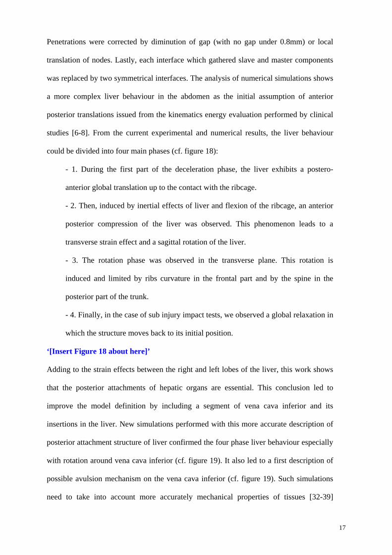
could be divided into four main phases (cf. figure 18):
- 1. During the first part of the deceleration phase, the liver exhibits a postero-
anterior global translation up to the contact with the ribcage.
- 2. Then, induced by inertial effects of liver and flexion of the ribcage, an anterior
posterior compression of the liver was observed. This phenomenon leads to a
transverse strain effect and a sagittal rotation of the liver.
- 3. The rotation phase was observed in the transverse plane. This rotation is
induced and limited by ribs curvature in the frontal part and by the spine in the
posterior part of the trunk.
- 4. Finally, in the case of sub injury impact tests, we observed a global relaxation in
which the structure moves back to its initial position.
‘[Insert Figure 18 about here]’
Adding to the strain effects between the right and left lobes of the liver, this work shows
that the posterior attachments of hepatic organs are essential. This conclusion led to
improve the model definition by including a segment of vena cava inferior and its
insertions in the liver. New simulations performed with this more accurate description of
posterior attachment structure of liver confirmed the four phase liver behaviour especially
with rotation around vena cava inferior (cf. figure 19). It also led to a first description of
possible avulsion mechanism on the vena cava inferior (cf. figure 19). Such simulations
need to take into account more accurately mechanical properties of tissues [32-39]
17
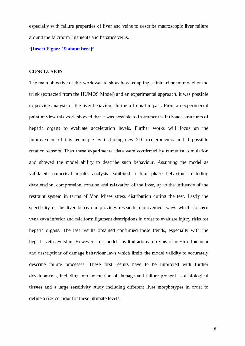
especially with failure properties of liver and veins to describe macroscopic liver failure
around the falciform ligaments and hepatics veins.
‘[Insert Figure 19 about here]’
CONCLUSION
The main objective of this work was to show how, coupling a finite element model of the
trunk (extracted from the HUMOS Model) and an experimental approach, it was possible
to provide analysis of the liver behaviour during a frontal impact. From an experimental
point of view this work showed that it was possible to instrument soft tissues structures of
hepatic organs to evaluate acceleration levels. Further works will focus on the
improvement of this technique by including new 3D accelerometers and if possible
rotation sensors. Then these experimental data were confirmed by numerical simulation
and showed the model ability to describe such behaviour. Assuming the model as
validated, numerical results analysis exhibited a four phase behaviour including
deceleration, compression, rotation and relaxation of the liver, up to the influence of the
restraint system in terms of Von Mises stress distribution during the test. Lastly the
specificity of the liver behaviour provides research improvement ways which concern
vena cava inferior and falciform ligament descriptions in order to evaluate injury risks for
hepatic organs. The last results obtained confirmed these trends, especially with the
hepatic vein avulsion. However, this model has limitations in terms of mesh refinement
and descriptions of damage behaviour laws which limits the model validity to accurately
describe failure processes. These first results have to be improved with further
developments, including implementation of damage and failure properties of biological
tissues and a large sensitivity study including different liver morphotypes in order to
define a risk corridor for these ultimate levels.
18
Lastly, liver injuries can not only be attributed to pure frontal deceleration effects. In
many real life situations like car lateral impacts, decelerations are coupled with
penetration effects. The results obtained in the work need to be extended to such
situations.
ACKNOWLEDGMENTS
The experimental part of this study was partially supported by the European Community
in the framework of the HUMOS2 project G3RD-CT-2002-00803.
REFERENCES
[1] CIREN, 2000, NHTSA CIREN Program Report
[2] Yogonandan n., Pintar F. A., Maltese M.R., 2001, Biomechanics of abdominal
injuries, Critical Reviews in Biomedical Engineering, 29(2), pp. 173-246
[3] Lee J.B., Yang K.H., 2002 Abdominal injury patterns in motor vehicle accidents : a
survey of the NASS database from 1993 to 1997, Traffic Injury Prevention, Vol. 3,
N°3, pp. 241-246
[4] Augenstein JS, Perdeck E, Bowen J, Stratton J, Horton T, Singer M, Digges KH.,
Steps JH. Injuries to Restrained Occupants in Far-Side Crashes. 44th Annual
Proceedings, Association for the Advancement of Automotive Medicine, October
2000, p. 57.
[5] Augenstein JS, Perdeck E, Bowen J, Stratton J., Horton T, Singer M, Digges KH,
Malliaris AC, Steps J. Dummy Measurement of Chest Injuries Induced by Two-Point
Shoulder Belts. 44th Annual Proceedings, Association for the Advancement of
Automotive Medicine, October, 2000, p. 1.
[6] Chevalier J.M., Jost J.L., Vayre P., (1991), Traumatismes du foie – Lésions
anatomiques, essai de classification, Journal de chirurgie, Vol. 128, N°12, pp. 509-
510
19
[7] Létoublon C., Castaing D., (1996), Les traumatismes fermés du foie, 98ème congrès
français de chirurgie, pp. 20- 58
[8] Contoslavos DL, Laposata E.A. (1992), Sagittal liver transection –an injury from
improperly worn shoulder harness seatbelts : a report of two cases, J. Trauma, 33,
(4), 637-640.
[9] Brunet C., Sielezneff I., Thomas P., Thirion X., Sastre B., Farisse J. (1994),
Treatment of hepatic trauma with perihepatic mesh: 35 cases. The Journal of
Trauma, 37(2):200-203
[10] Walfisch G., Fayon A., Tarrière C. & al. (1980), Designing of a dummy’s abdomen
for detecting injuries in side impact collisions. Fifty international IRCOBI
Conference Proceedings, pp. 149-164
[11] Nusholtz G.S., Melvin J.W., Mueller G. & al., (1980), Thoracoabdominal response
and injury. 24th Stapp Car Crash Conference Proceedings, pp. 187-228
[12] Kroell C.K., Pope M.E., Viano D.C, (1981), Interrelationship of velocity and chest
compression in blunt thoracic impact, 25th Stapp Car Crash Conference, SAE
811016, pp 549-579
[13] Klaus G., Kallieris D., (1983), Side impact : a comparison between HSRI, APROD
and Hybrid II dummies and cadavers, 27th Stapp Car Crash Conference, SAE
831630, pp 134
[14] Rouhana S. W., Kroell C.K., (1989), The effect of door topography on abdominal
injury in lateral impact, 33th Stapp Car Crash Conference Proceedings, n°892433, pp.
227
[15] Viano D.C., (1989), Biomechanical responses and injuries in blunt lateral impact,
SAE Proceedings of the 33th Stapp Car Crash Conference, pp. 113-142
[16] Viano D.C., Andrzejak D., (1993), Biomechanics of abdominal injuries by armrest
loading, The Journal of Trauma, vol. 34, N. 1, pp. 105-115
20
[17] Talantikite Y., Brun Cassan F., Lecoz J.Y., Tarrierre C., (1993), Abdominal
protection in side impact injury mechansims and protection criteria, IRCOBI
Conference Proceedings, pp. 131-144
[18] Behr M., Arnoux P.-J., Serre T., Bidal S., Kang H.S., Thollon L., Cavallero C.,
Kayvantash K., Brunet C. (2003), A human model for road safety: from geometrical
acquisition to model validation with Radioss. Computer methods in biomechanics
and biomedical engineering, Vol 6 n°4, 2003, pp263-273.
[19] Ghannouchi S, Ghorbel A, Cavallero C, Bonnoit J (1993) Anatomy of the seated
position : methodologic approach and initial findings. Surgical Radiology Anatomy,
Vol. 15, pp. 315-319
[20] Serre, T., Brunet C., Durand F., Bidal S., Ghannouchi S., Behr M., Cavallero C.,
Bonnoit J., (2002), The seated man : geometry acquisition and 3D reconstruction
Surgical and Radiologic Anatomy Volume24, Issue 6 pp381-386 - Springer-Verlag
[21] Viano D.C., Lau I., (1983), Role of Impact velocity and chest compression in
thoracic injury. Aviat. Space Environ. Med., 54, pp. 16-21
[22] Viano D.C., (1986), Biomechanics of bone and tissue : a review of material
properties and failures characteristics, SAE, pp 33-63
[23] Yamada H., (1970), Strength of biological materials, the William and Wilkins
Company Baltimore
[24] Fung Y.C., (1993), Biomechanics: Materials properties of living tissue, Springer
Verlag.
[25] Arnoux P.J., Kang H.S., Thollon L., Kayvantash K., (2001), Radioss Humos model
guidelines, Mecalog safety business unit©.
[26] Arnoux P.J., Kang H.S., Kayvantash K., (2001), HUMOS project Deliverable WP5-6,
European 5th framework, deliverable 6ISA /010710/E1/DA
21
[27] Dan D., (1999) Caractérisation mécanique du foie humain en situation de choc. Ph D
dissertation, Université Paris 7
[28] Lizée E, Robin S. et al, Besnault B. and al., (1998), “Development of a 3D Finite
Element Model of the Human Body”. 42th Stapp Car Crash Conference, Paper n°
983152.
[29] Lizée E. et al, Song E. et al., (1998), “Finite element model of the human thorax
validated in frontal, oblique and lateral impacts : a tool to evaluate new restraint
systems”. Proceedings of the International IRCOBI Conference on the biomechanics
of impact
[30] Cavanaugh J.M., Nyquist G.W., Goldberg S.J., King A. I., (1986), Lower abdominal
tolerance and response, SAE, Paper N° 861878.
[31] Winckler G., (1974), Manuel d’anatomie topographique et fonctionnelle, Masson Ed.
[32] Jian, C., & Wang, G. (1991) Biomechanical study of the bile duct system outside the
liver. Bio-Medical Materials & Engineering, Vol. 1, pp. 105-113.
[33] Liu, Z., & Bilston, L. (2000) On the viscoelastic character of liver tissue: experiments
and modelling of the linear behaviour. Biorheology, Vol. 37, pp. 191-201.
[34] Liu, Z., & Bilston, L. E. (2002) Large deformation shear properties of liver tissue.
Biorheology, Vol. 39, pp. 735-742.
[35] Miller, K. (2000) Constitutive modelling of abdominal organs. Journal of
Biomechanics, Vol. 33, pp. 367-373.
[36] Seki, S., & Iwamoto, H. (1998) Disruptive forces for swine heart, liver, and spleen:
Their breaking stresses. Journal of Trauma-Injury Infection & Critical Care, Vol. 45,
pp. 1079-1083.
[37] Wang, B. C., Wang, G. R., Yan, D. H., & Liu, Y. P. (1992) An experimental study on
biomechanical properties of hepatic tissue using a new measuring method. Bio-
Medical Materials & Engineering, Vol. 2, pp. 133-138.
22
[38] Koop B.E., Lewis J.L., (2003), A model of fracture testing of soft viscoelastic tissues.
Journal of Biomechanics, Vol. 36, pp. 605-608
[39] Rubin M.B., Bodner S.R., (2002) A three dimensional nonlinear model for dissipative
response of soft tissue, International Journal of Solids and Structures, Vol 39, pp.
5081-5099.
[40] Demetropoulos C.K., Yang K.H., Grimm M.J., Khalil T., King A.I, (1998),
Mechanical properties of the cadaveric and Hybrid III lumbar spines, Proceedings of
the 42nd STAPP Car Crash Conference
[41] Kalieris D., Riedl H., (1998), Experimental activity WP3.2, European 5th framework
HUMOS deliverable 3HEI/981110/T1/DA,
[42] Bouquet R., Ramet M., Bermond F., Cesari D., Thoracic and human pelvis response
to impact, Porceedings of the 14th International technical conference on enhanced
safety of vehicles, pp. 100-109
[43] Kroell, C.K., Schneider, D.C., Nahum, A.M. (1971). Impact tolerance and response
of the human thorax. In: Proc. 15th Stapp Car Crash Conference, pp. 84–134. Paper
No. 710851.
[44] Kroell, C.K., Schneider, D.C., Nahum, A.M. (1974). Impact tolerance and response
of the human thorax II. In: Proc. 18th Stapp Car Crash Conference, pp. 383–457.
Paper No. 741187.
[45] Nahum A.M., Melvin J., (1985), The biomechanics of trauma, Appleton century
crofts
[46] Vezin P., (2000), PMHS tests and analysis, HUMOS project Deliverable WP4,
European 5th framework, deliverable 4INR /000605/T1/DB
[47] Hardy WN, Foster C, Mason M, Yang KH, King AI, Tashman S., (2001)
Investigation of head injury mechanisms using neutral density technology and high-
speed biplanar X-ray. Stapp Car Crash Journal, Vol. 45, pp. 337–368.
23

[48] Lemaitre J., Chaboche, J.L. (1990), Mechanics of Solids, Cambridge University
Press.
[49] Christensen, R.M., (1982), Theory of Viscoelasticity. Academic Press, New York.
[50] Melvin JW., Stalnaker RL., Roberts VL. (1973), Impact injury mechanisms in
abdominal organs, 17th Stapp Car Crash Conference, Paper 730968
[51] Schittkowski K. (1986): NLPQL: A FORTRAN subroutine solving constrained
nonlinear programming problems, Annals of Operations Research, Vol. 5, pp. 485-500
24
List of tables
Parts K G0 GI β ρ (kg/m3)
Organ_Spleen 0.25 0.054 0.04 1 1000 Organ_Intestine 0.001 0.036 0.027 1 1000 Organ_Kidney_L&R 0.166 0.045 0.036 1 1000 Organ_Stomach 0.25 0.054 0.04 1 1000 Organ_Liver 0.166 0.045 0.036 1 1000 Flesh_Abdominal 0.01 0.045 0.036 1 1000
Table 1: Summary of Boltzmann viscoelastic properties of internal organs with K the Bulk modulus, G0 the Short time shear modulus, GI the long time shear modulus, β the decay constant and ρ the density [21-29]
Parts E (Mpa)
ν ρ (kg/m3)
η0
Muscle_Pelvabdo 0.532 0.43 1000 5 Muscle_Gluteal_L&R 0.532 0.43 1000 5 Flesh_Pelvic 0.532 0.43 900 5 Thoracic & abdominal connective tissue 0.532 0.43 900 5
Table 2: Summary of connective tissue main parameters for Trunk segment using Pointing Thomson behaviour law with E the Younk modulus, ν the Poisson ratio, ρ the density and η
Compact SpongiousYoung Modulus 9-15 GPa 10-450 MPaPoisson ratio 0,3 0,3Yield stress 80-120 MPa 10 MPaUltimate stress 110-130 MPa 15 MPaHardening (param & coel) 100 MPa, 0,1 100 MPa, 0,1Ultimate strain 2-3 % 3%
Table 3: Summary of elastoplastic properties of bones [18, 25, 26]
COMPONENT TEST ReferencesTRUNKLumbar spine: Demetropoulos flexion extension [40]Rib: quasi static and dynamic bending [18,25,41]Clavicle: Quasi static en dynamic bending [18,25,41]Clavicle: Quasi static axial compression [18,25,41]
WHOLE MODEL TESTSTRUNKThorax bouquet frontal impact [42]Thorax Kroell frontal impact [43,44]Thorax Nahum frontal impact [45]Thoarx Lizee lateral impact [28, 29]Thorax Talantikite lateral impact [17]Thorax Viano oblique impact [15]Abdomen Cavanaugh frontal impact [30]Abdomen Viano oblique impact [15]Pelvis Bouquet lateral impact [42]Pelvis Viano lateral impact [15]INRET-Bron Frontal sled tests [18,25,46]
Table 4: Overview of model validation database regarding trunk segment
25
List of figures
Figure 1: Global overview of the HUMOS model in sitting position
b a c d Figure 2: From left to right : (a) Spleen stomach attachments (left picture); (b) Peritoneal membrane intestine attachments (right picture) to model mesentery, (c) Stomach liver attachments ; (d) Peritoneal membrane liver attachments
26
0 0.01 0.02 0.03 0.04 0.05
1000
2000
3000
4000
5000
Temps (s)
Forc
e (N
)
Impactor force versus time
0 0.01 0.02 0.03 0.04 0.05
1000
2000
3000
4000
5000
Temps (s)
Forc
e (N
)
0 0.01 0.02 0.03 0.04 0.05
1000
2000
3000
4000
5000
Temps (s)
Forc
e (N
)
Impactor force versus time
Time (s)0 0.1 0.2 0.3 0.4 0.5 0.6
2000
4000
6000
8000
10000
12000
Forc
e (N
)
Force versus Time curves
Time (s)0 0.1 0.2 0.3 0.4 0.5 0.6
2000
4000
6000
8000
10000
12000
Forc
e (N
)
Time (s)0 0.1 0.2 0.3 0.4 0.5 0.6
2000
4000
6000
8000
10000
12000
Forc
e (N
)
Force versus Time curves
Time (s)0 0.1 0.2 0.3 0.4 0.5 0.6
2000
4000
6000
8000
10000
12000
Forc
e (N
)Force versus Time curves
Time (s)0 0.1 0.2 0.3 0.4 0.5 0.6
2000
4000
6000
8000
10000
12000
Forc
e (N
)Force versus Time curves
Figure 3: from left to right Cavanaugh 6.9 m/s, 31.4 kg impacts results and 9.4 m/s, 63.6 kg impact results
27
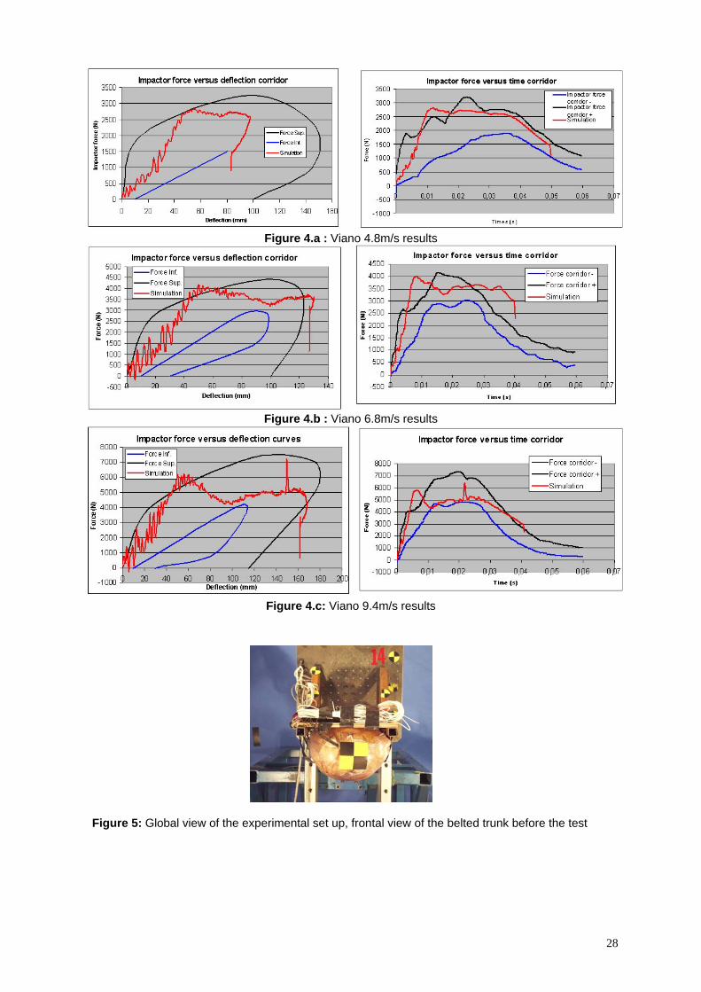
Figure 4.a : Viano 4.8m/s results
Figure 4.b : Viano 6.8m/s results
Figure 4.c: Viano 9.4m/s results
Figure 5: Global view of the experimental set up, frontal view of the belted trunk before the test
28
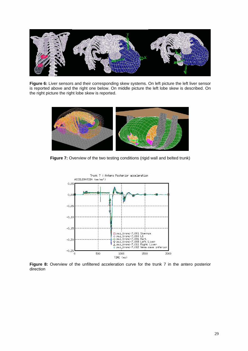
Figure 6: Liver sensors and their corresponding skew systems. On left picture the left liver sensor is reported above and the right one below. On middle picture the left lobe skew is described. On the right picture the right lobe skew is reported.
Figure 7: Overview of the two testing conditions (rigid wall and belted trunk)
Figure 8: Overview of the unfiltered acceleration curve for the trunk 7 in the antero posterior direction
29
A
B
C D
Figure 9 : Trunk 7 curvilinear velocity in antero posterior and latero medial direction by integration of 1D accelerations data. From A to B the acceleration phase of the system, from B to C the deceleration phase of the trunk up to first zero velocity and from C to D and after, the rebound phase with D the maximal velocity in the rebound phase.
Figure 10: Comparison of experiment and numerical smoothed acceleration versus time curves for Test 13 with trunk on a rigid plate and test 15 for a belted trunk
30
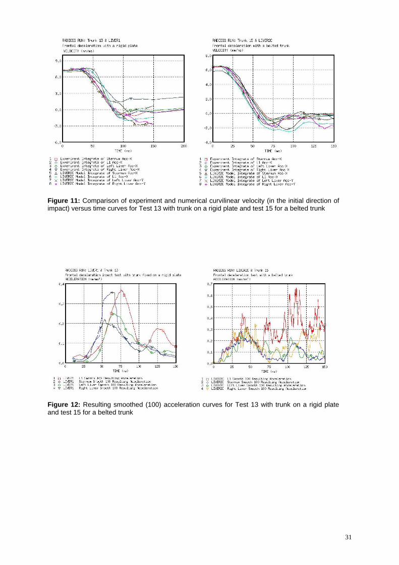
Figure 11: Comparison of experiment and numerical curvilinear velocity (in the initial direction of impact) versus time curves for Test 13 with trunk on a rigid plate and test 15 for a belted trunk
Figure 12: Resulting smoothed (100) acceleration curves for Test 13 with trunk on a rigid plate and test 15 for a belted trunk
31
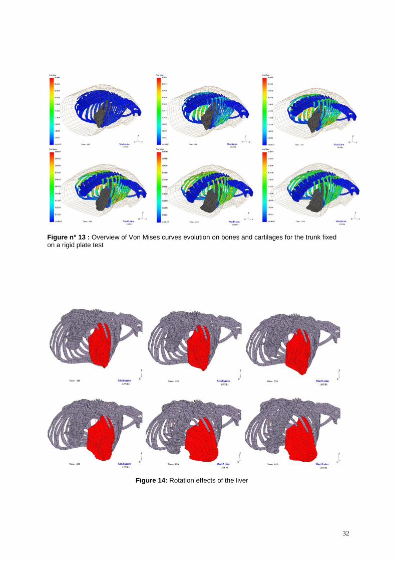
Figure n° 13 : Overview of Von Mises curves evolution on bones and cartilages for the trunk fixed on a rigid plate test
Figure 14: Rotation effects of the liver
32
Rotations (°) Rotations (°)
Figure 15: Rotation effects (in degrees) versus Time (ms) of the right and left sensors of the liver
Figure 16: Comparison of Right and Left Liver resultant acceleration for reference test, 0,2 friction coefficient and 0,4 friction coefficient for all abdominal interfaces.
33
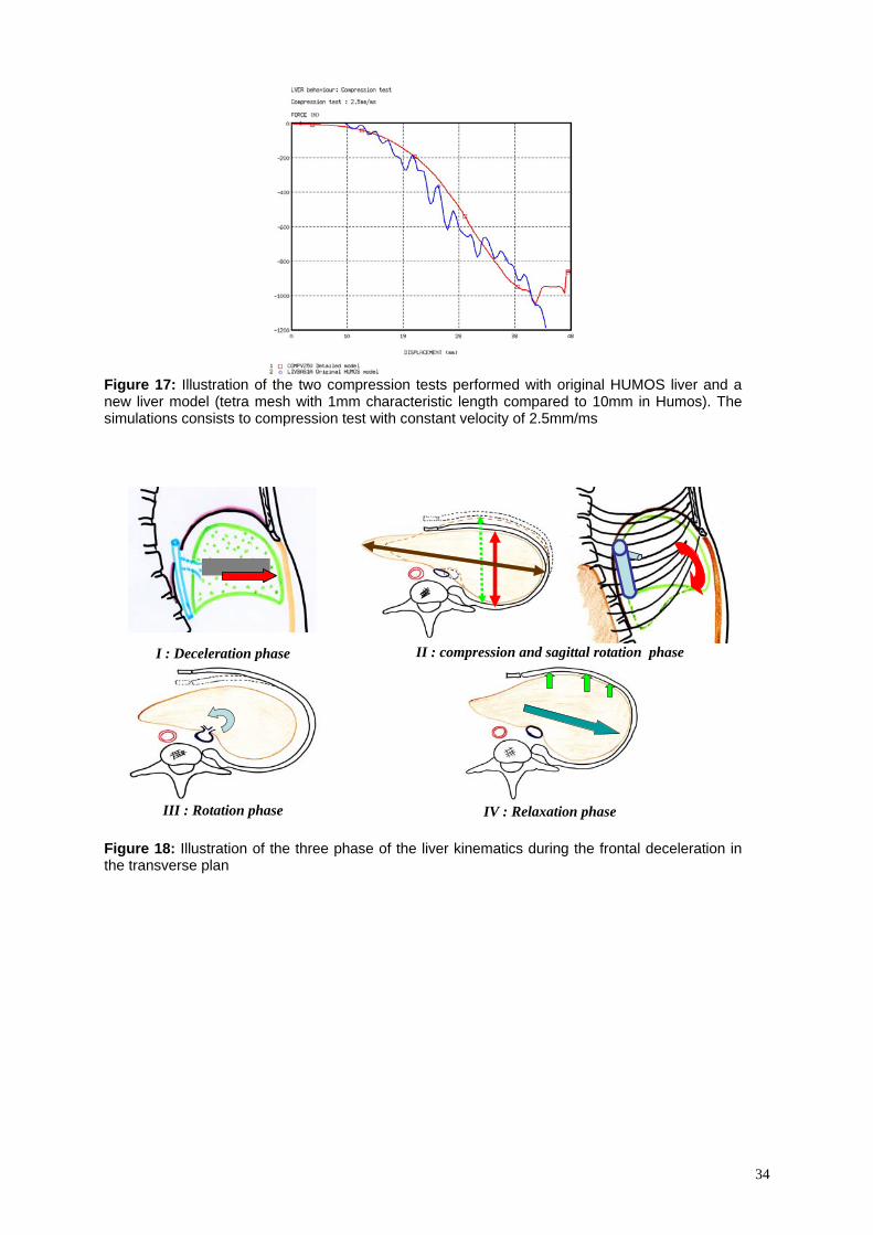
Figure 17: Illustration of the two compression tests performed with original HUMOS liver and a new liver model (tetra mesh with 1mm characteristic length compared to 10mm in Humos). The simulations consists to compression test with constant velocity of 2.5mm/ms
I : Deceleration phase
II : compression and sagittal rotation phase
III : Rotation phase
IV : Relaxation phase
Figure 18: Illustration of the three phase of the liver kinematics during the frontal deceleration in the transverse plan
34
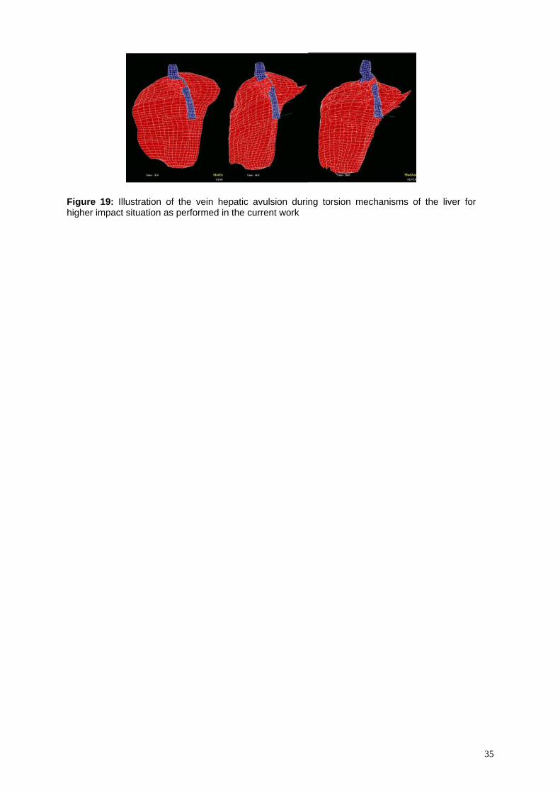
Figure 19: Illustration of the vein hepatic avulsion during torsion mechanisms of the liver for higher impact situation as performed in the current work
35


![ESTIMATING PRELIMINARY OCCUPANT INJURY RISK … · The dummy used in most frontal crash tests, the Hybrid III 50th percentile male, is only calibrated with frontal crash loading [12]](https://img.pdfslide.net/doc/110x75/5e4f035f96437c097d7bebb6/estimating-preliminary-occupant-injury-risk-the-dummy-used-in-most-frontal-crash.jpg)


![Frontal Pole Impacts - IRCOBI Based on past findings that the between‐rail frontal crash has a higher ... They observed that the federal statistics for 2008 in ... [22]. In an effort](https://img.pdfslide.net/doc/110x75/5ab40b1b7f8b9a1a048b8606/frontal-pole-impacts-based-on-past-findings-that-the-betweenrail-frontal-crash.jpg)