Embed Size (px)
Citation preview
GEOTECH SYSTEMS LTD - Box 6035 - TAURANGA 3146
Rev June 2013 Sales orders / enquiries - Email [email protected] - Phone 0800 436 832 - www.geotechsystems.co.nz Page 6 of 39
LIVING EARTH GREEN WALL™ WELDED STEEL MESH FACING COMBINED WITH GEOGRID REINFORCED SOILS
THE ABOVE PHOTOS ARE REPRESENTATIVE OF RECENT EUROPEAN PROJECTS CONSTRUCTED
USING TENAX ‘TT’ HDPE GEOGRIDS AND HUESKER FORTRAC POLYESTER GEOGRIDS
GEOTECH SYSTEMS LTD - Box 6035 - TAURANGA 3146
Rev June 2013 Sales orders / enquiries - Email [email protected] - Phone 0800 436 832 - www.geotechsystems.co.nz Page 7 of 39
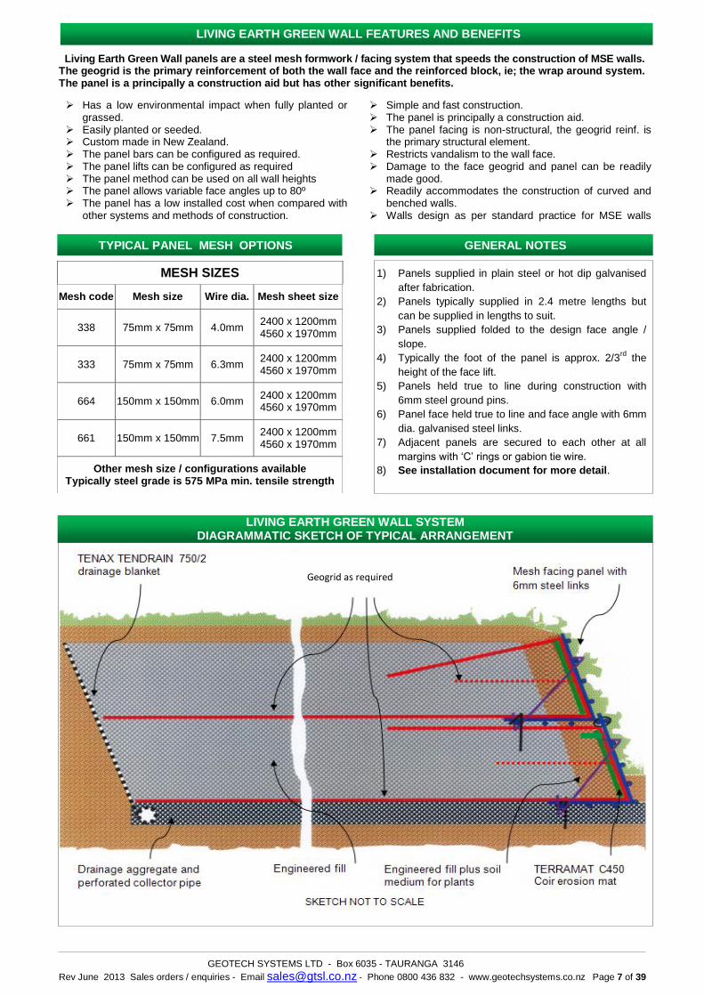
Living Earth Green Wall panels are a steel mesh formwork / facing system that speeds the construction of MSE walls. The geogrid is the primary reinforcement of both the wall face and the reinforced block, ie; the wrap around system. The panel is a principally a construction aid but has other significant benefits.
Has a low environmental impact when fully planted or grassed.
Easily planted or seeded. Custom made in New Zealand. The panel bars can be configured as required. The panel lifts can be configured as required The panel method can be used on all wall heights The panel allows variable face angles up to 80º The panel has a low installed cost when compared with
other systems and methods of construction.
Simple and fast construction. The panel is principally a construction aid. The panel facing is non-structural, the geogrid reinf. is
the primary structural element. Restricts vandalism to the wall face. Damage to the face geogrid and panel can be readily
made good. Readily accommodates the construction of curved and
benched walls. Walls design as per standard practice for MSE walls
MESH SIZES
Mesh code Mesh size Wire dia. Mesh sheet size
338 75mm x 75mm 4.0mm 2400 x 1200mm 4560 x 1970mm
333 75mm x 75mm 6.3mm 2400 x 1200mm 4560 x 1970mm
664 150mm x 150mm 6.0mm 2400 x 1200mm 4560 x 1970mm
661 150mm x 150mm 7.5mm 2400 x 1200mm 4560 x 1970mm
Other mesh size / configurations available Typically steel grade is 575 MPa min. tensile strength
LIVING EARTH GREEN WALL SYSTEM DIAGRAMMATIC SKETCH OF TYPICAL ARRANGEMENT
TYPICAL PANEL MESH OPTIONS
GENERAL NOTES
1) Panels supplied in plain steel or hot dip galvanised
after fabrication.
2) Panels typically supplied in 2.4 metre lengths but
can be supplied in lengths to suit.
3) Panels supplied folded to the design face angle /
slope.
4) Typically the foot of the panel is approx. 2/3rd
the
height of the face lift.
5) Panels held true to line during construction with
6mm steel ground pins.
6) Panel face held true to line and face angle with 6mm
dia. galvanised steel links.
7) Adjacent panels are secured to each other at all
margins with ‘C’ rings or gabion tie wire.
8) See installation document for more detail.
LIVING EARTH GREEN WALL FEATURES AND BENEFITS
Geogrid as required
GEOTECH SYSTEMS LTD - Box 6035 - TAURANGA 3146
Rev. June 2013 Sales orders / enquiries - Email [email protected] - Phone 0800 436 832 - www.geotechsystems.co.nz Page 8 of 39
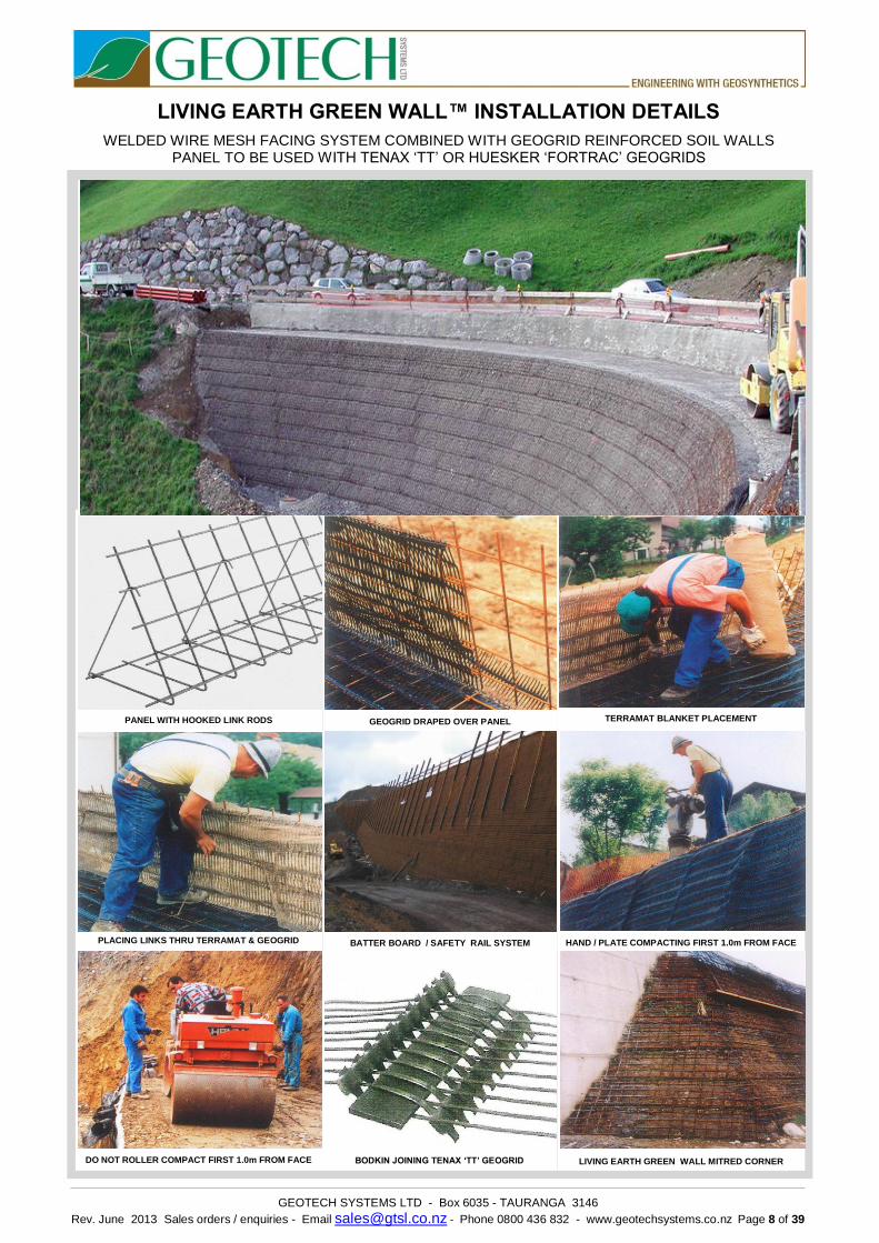
LIVING EARTH GREEN WALL™ INSTALLATION DETAILS
WELDED WIRE MESH FACING SYSTEM COMBINED WITH GEOGRID REINFORCED SOIL WALLS PANEL TO BE USED WITH TENAX ‘TT’ OR HUESKER ‘FORTRAC’ GEOGRIDS
PANEL WITH HOOKED LINK RODS
GEOGRID DRAPED OVER PANEL
TERRAMAT BLANKET PLACEMENT
PLACING LINKS THRU TERRAMAT & GEOGRID
BATTER BOARD / SAFETY RAIL SYSTEM
HAND / PLATE COMPACTING FIRST 1.0m FROM FACE
DO NOT ROLLER COMPACT FIRST 1.0m FROM FACE
BODKIN JOINING TENAX ‘TT’ GEOGRID
LIVING EARTH GREEN WALL MITRED CORNER
GEOTECH SYSTEMS LTD - Box 6035 - TAURANGA 3146
Rev. June 2013 Sales orders / enquiries - Email [email protected] - Phone 0800 436 832 - www.geotechsystems.co.nz Page 9 of 39
Secure geogrid into corner of panel
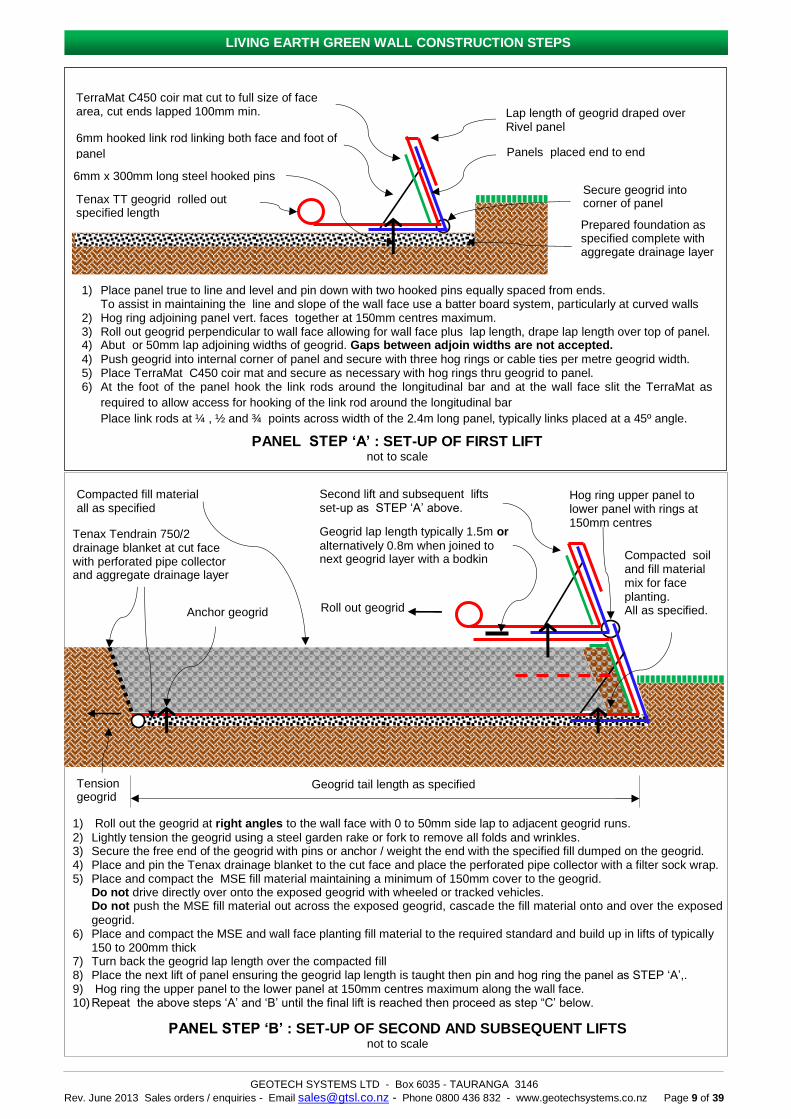
1) Place panel true to line and level and pin down with two hooked pins equally spaced from ends. To assist in maintaining the line and slope of the wall face use a batter board system, particularly at curved walls 2) Hog ring adjoining panel vert. faces together at 150mm centres maximum. 3) Roll out geogrid perpendicular to wall face allowing for wall face plus lap length, drape lap length over top of panel. 4) Abut or 50mm lap adjoining widths of geogrid. Gaps between adjoin widths are not accepted.
4) Push geogrid into internal corner of panel and secure with three hog rings or cable ties per metre geogrid width. 5) Place TerraMat C450 coir mat and secure as necessary with hog rings thru geogrid to panel. 6) At the foot of the panel hook the link rods around the longitudinal bar and at the wall face slit the TerraMat as
required to allow access for hooking of the link rod around the longitudinal bar
Place link rods at ¼ , ½ and ¾ points across width of the 2.4m long panel, typically links placed at a 45º angle.
PANEL STEP ‘A’ : SET-UP OF FIRST LIFT not to scale
TerraMat C450 coir mat cut to full size of face area, cut ends lapped 100mm min.
6mm x 300mm long steel hooked pins
Lap length of geogrid draped over Rivel panel
Panels placed end to end
Tenax TT geogrid rolled out specified length
Prepared foundation as specified complete with aggregate drainage layer
6mm hooked link rod linking both face and foot of
panel
Compacted fill material all as specified
Tenax Tendrain 750/2 drainage blanket at cut face with perforated pipe collector and aggregate drainage layer
Geogrid lap length typically 1.5m or
alternatively 0.8m when joined to next geogrid layer with a bodkin
Second lift and subsequent lifts set-up as STEP ‘A’ above.
Hog ring upper panel to lower panel with rings at 150mm centres
Compacted soil and fill material mix for face planting. All as specified.
Geogrid tail length as specified
Anchor geogrid
1) Roll out the geogrid at right angles to the wall face with 0 to 50mm side lap to adjacent geogrid runs. 2) Lightly tension the geogrid using a steel garden rake or fork to remove all folds and wrinkles. 3) Secure the free end of the geogrid with pins or anchor / weight the end with the specified fill dumped on the geogrid. 4) Place and pin the Tenax drainage blanket to the cut face and place the perforated pipe collector with a filter sock wrap. 5) Place and compact the MSE fill material maintaining a minimum of 150mm cover to the geogrid.
Do not drive directly over onto the exposed geogrid with wheeled or tracked vehicles. Do not push the MSE fill material out across the exposed geogrid, cascade the fill material onto and over the exposed
geogrid. 6) Place and compact the MSE and wall face planting fill material to the required standard and build up in lifts of typically
150 to 200mm thick 7) Turn back the geogrid lap length over the compacted fill 8) Place the next lift of panel ensuring the geogrid lap length is taught then pin and hog ring the panel as STEP ‘A’,. 9) Hog ring the upper panel to the lower panel at 150mm centres maximum along the wall face. 10) Repeat the above steps ‘A’ and ‘B’ until the final lift is reached then proceed as step “C’ below.
PANEL STEP ‘B’ : SET-UP OF SECOND AND SUBSEQUENT LIFTS not to scale
Tension geogrid
Roll out geogrid
LIVING EARTH GREEN WALL CONSTRUCTION STEPS
GEOTECH SYSTEMS LTD - Box 6035 - TAURANGA 3146
Rev. June 2013 Sales orders / enquiries - Email [email protected] - Phone 0800 436 832 - www.geotechsystems.co.nz Page 10 of 39
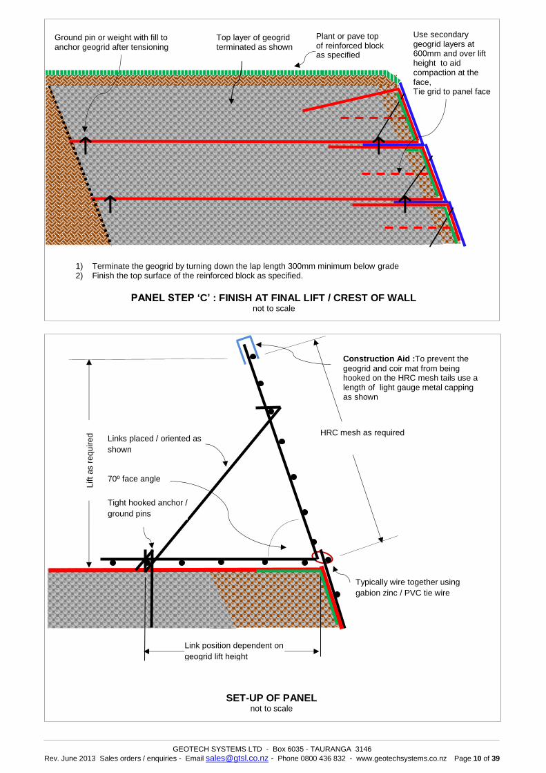
1) Terminate the geogrid by turning down the lap length 300mm minimum below grade 2) Finish the top surface of the reinforced block as specified.
PANEL STEP ‘C’ : FINISH AT FINAL LIFT / CREST OF WALL not to scale
Top layer of geogrid terminated as shown
Plant or pave top of reinforced block as specified
Use secondary geogrid layers at 600mm and over lift height to aid compaction at the face, Tie grid to panel face
Ground pin or weight with fill to anchor geogrid after tensioning
SET-UP OF PANEL not to scale
Lift
as r
equired
Links placed / oriented as
shown
HRC mesh as required
Link position dependent on
geogrid lift height
70º face angle
Tight hooked anchor /
ground pins
Typically wire together using
gabion zinc / PVC tie wire
Construction Aid :To prevent the
geogrid and coir mat from being hooked on the HRC mesh tails use a length of light gauge metal capping as shown
GEOTECH SYSTEMS LTD - Box 6035 - TAURANGA 3146
Rev. June 2013 Sales orders / enquiries - Email [email protected] - Phone 0800 436 832 - www.geotechsystems.co.nz Page 11 of 39
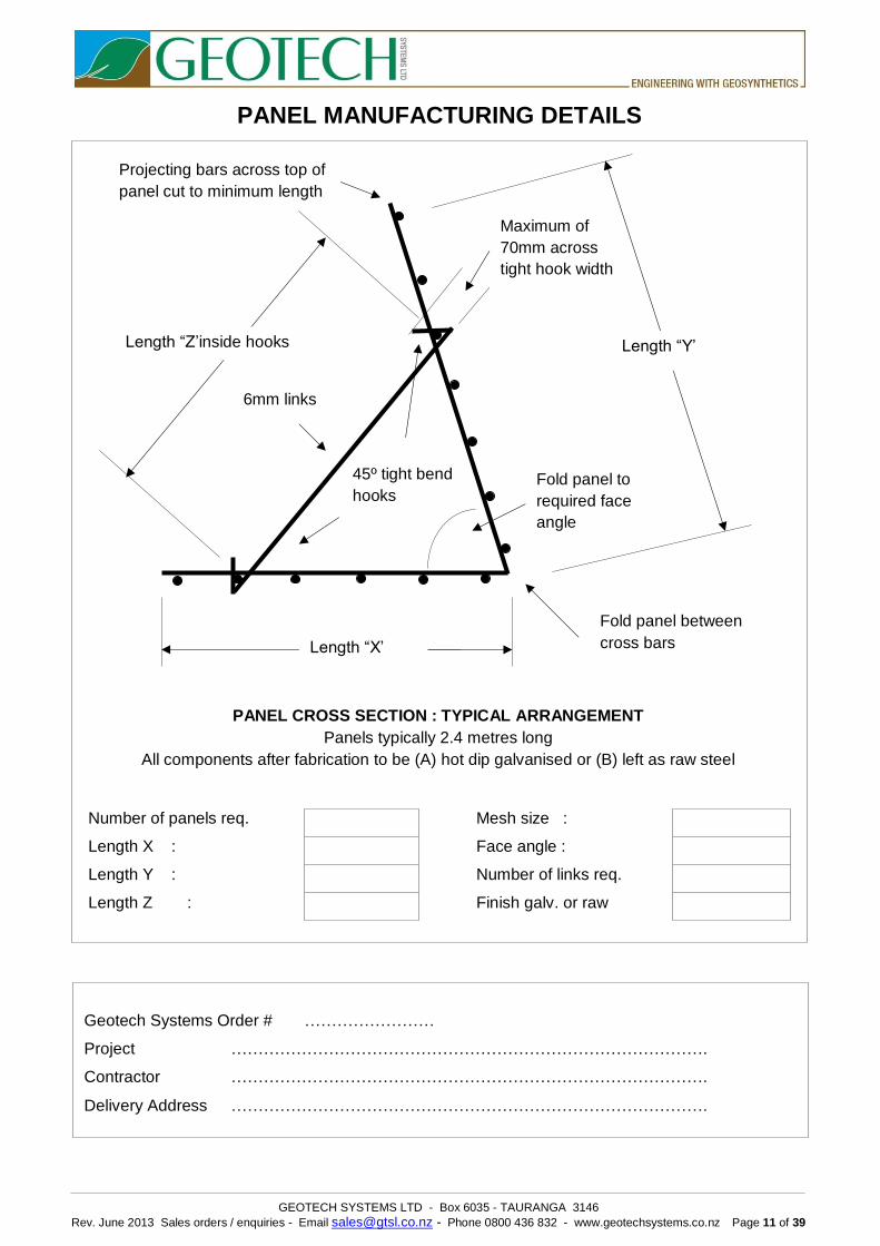
PANEL MANUFACTURING DETAILS
RIVEL PANEL LIVING EARTH GREEN WALL™ INSTALLATION DETAILS
Length “X’
45º tight bend
hooks
6mm links
(B) (
Fold panel between
cross bars
Fold panel to
required face
angle
Maximum of
70mm across
tight hook width
Projecting bars across top of
panel cut to minimum length
Length “Y’ Length “Z’inside hooks
Number of panels req. Mesh size :
Length X : Face angle :
Length Y : Number of links req.
Length Z : Finish galv. or raw
PANEL CROSS SECTION : TYPICAL ARRANGEMENT
Panels typically 2.4 metres long
All components after fabrication to be (A) hot dip galvanised or (B) left as raw steel
Geotech Systems Order # ……………………
Project …………………………………………………………………………….
Contractor …………………………………………………………………………….
Delivery Address …………………………………………………………………………….