Embed Size (px)
Citation preview
LJ276M/LJ276MT-2 GASOLING ENGING
SERVICE MANUAL
Shanghai Goka Sports Motor Co., Ltd
1
CONTENTS DRAWING Chapter one: Engine technical data and specification……………………………….………..2
1.1 Engine technical data and specification……………………………………………………2
1.2 Petrol Engine External Character Curve…………………………………………………....5
Chapter two: Engine operation……………………………………………………….………..6
2.1 Points for attention in engine operation……………………………………………6
2.2 Running-in of new engine………………………………………………………..6
2.3 Staring, Running and turning off engine…………………………………………...6
Chapter Three: Structural characteristics and assembly requirements of engine ……….8
3.1 Cylinder head assembly……………………….……………………………………………8
3.2 Cylinder block assembly and balance chain………………………………………………9
3.3 Crankshaft and main shaft bearing……………..…………………..………………….11
3.4 Piston and connecting rod assembly……………………………………...……………….12
3.5 Distributor assembly……………………………….………………………………..…….15
3.6 Carburetor assembly…………………………………………..…………………….…….16
3.7 Lubrication system………………………………………………………………………16
3.8 Cooling system……………………….…………………………………………..………..16
3.9 Electrical system…………………………………..……………………………..………..16
3.10 Clutch assembly and transmission assembly……………………………………..……….17
3.11 Engine leakage prevention……………………………………………………..…………18
Chapter Four: Engine maintenance…………………………………………………………..19
4.1 Engine maintenance cycle……………………………………..………………………….19
4.2 Point of attention for engine maintenance………………………………………………20
Chapter Five: Engine main troubles and remedies…………………………….…………….24
Appendix A: Fit Clearances of Main Components………………………..……………………27
Appendix B: Tightening Torque………………………………….…………………………….28
Appendix C: Sealing Surfaces and Sealant……………………………………………………29
2
CHAPTER ONE:
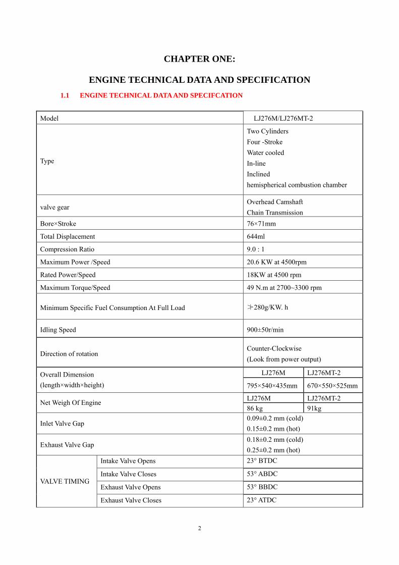
ENGINE TECHNICAL DATA AND SPECIFICATION 1.1 ENGINE TECHNICAL DATA AND SPECIFCATION
Model LJ276M/LJ276MT-2
Type
Two Cylinders Four -Stroke Water cooled In-line Inclined hemispherical combustion chamber
valve gear Overhead Camshaft Chain Transmission
Bore×Stroke 76×71mm
Total Displacement 644ml
Compression Ratio 9.0 : 1
Maximum Power /Speed 20.6 KW at 4500rpm
Rated Power/Speed 18KW at 4500 rpm
Maximum Torque/Speed 49 N.m at 2700~3300 rpm
Minimum Specific Fuel Consumption At Full Load ≯280g/KW. h
Idling Speed 900±50r/min
Direction of rotation Counter-Clockwise (Look from power output)
LJ276M LJ276MT-2 Overall Dimension (length×width×height) 795×540×435mm 670×550×525mm
LJ276M LJ276MT-2 Net Weigh Of Engine 86 kg 91kg
Inlet Valve Gap 0.09±0.2 mm (cold) 0.15±0.2 mm (hot)
Exhaust Valve Gap 0.18±0.2 mm (cold) 0.25±0.2 mm (hot)
Intake Valve Opens 23° BTDC
Intake Valve Closes 53° ABDC
Exhaust Valve Opens 53° BBDC VALVE TIMING
Exhaust Valve Closes 23° ATDC
3
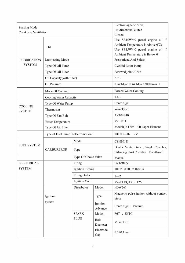
Starting Mode Crankcase Ventilation
Electromagnetic drive, Unidirectional clutch Closed
Oil
Use SE15W/40 petrol engine oil if Ambient Temperature is Above 0℃; Use SE15W/40 petrol engine oil if Ambient Temperature is Below 0
Lubricating Mode Pressurized And Splash
Type Of Oil Pump Cycloid Rotor Pump
Type Of Oil Filter Screwed joint J0706
Oil Capacity(with filter) 2.9L
LUBRICATION SYSTOM
Oil Pressure 0.245Mpa~0.440Mpa(3000r/min )
Mode Of Cooling Forced Water-Cooling
Cooling Water Capacity 1.4L
Type Of Water Pump Centrifugal
Thermostat Wax-Type
Type Of Fan Belt AV10×840
Water Temperature 75~95℃
COOLING SYSTEM
Type Of Air Filter ModelQK1706—00,Paper Element
Type of Fuel Pump(electromotion) JB12D—II,12V
Model CSH101E
Type Double Venturi tube , Single Chamber, Balancing Float Chamber Flat Absorb
FUEL SYSTEM CARBUREROR
Type Of Choke Valve Manual Firing By battery
Ignition Timing 10±2°BTDC 900r/min
Firing Order 1—2 Ignition Coil Model DQ130,12V
Model FDW261
Type Magnetic pulse igniter without contact piece
Distributor
Ignition Advance
Centrifugal,Vacuum
Model F6T 、E6TC
Bolt Diameter
M14×1.25
ELECTRICAL
SYSTEM
Ignition
system
SPARK PLUG
Electrode Gap
0.7±0.1mm
4
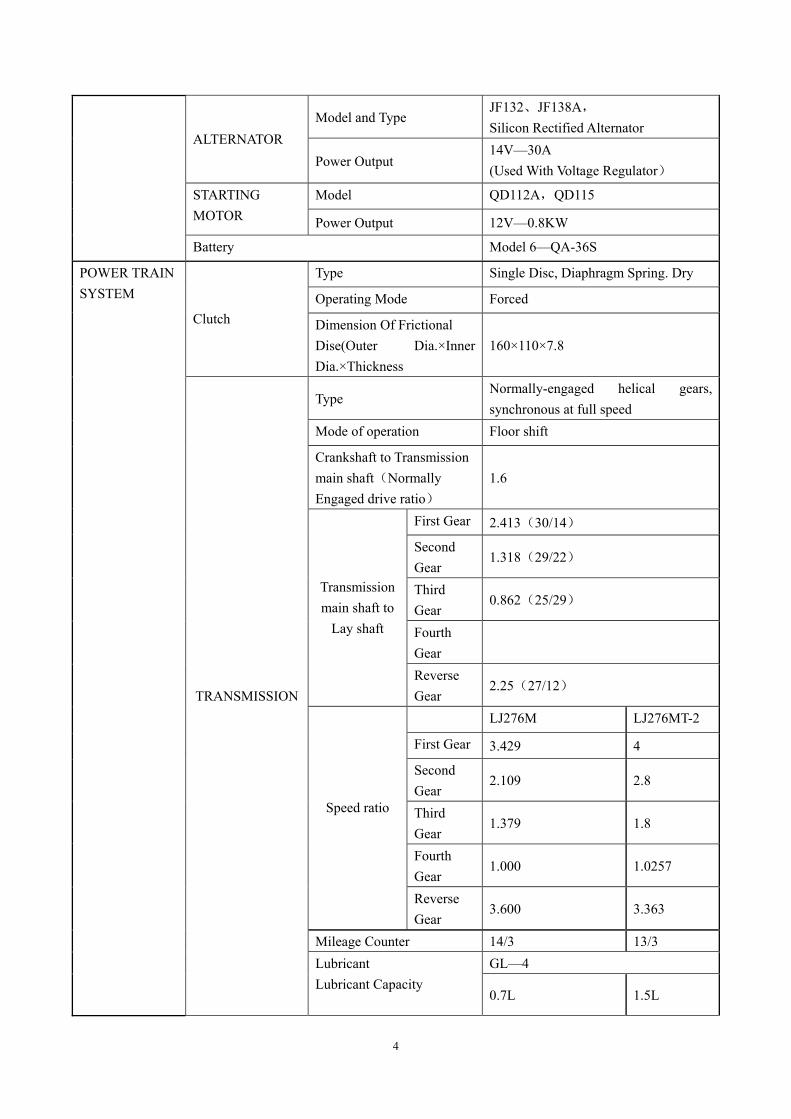
Model and Type JF132、JF138A, Silicon Rectified Alternator
ALTERNATOR Power Output
14V—30A (Used With Voltage Regulator)
Model QD112A,QD115 STARTING MOTOR Power Output 12V—0.8KW
Battery Model 6—QA-36S
Type Single Disc, Diaphragm Spring. Dry
Operating Mode Forced Clutch Dimension Of Frictional
Dise(Outer Dia.×Inner Dia.×Thickness
160×110×7.8
Type Normally-engaged helical gears, synchronous at full speed
Mode of operation Floor shift
Crankshaft to Transmission main shaft(Normally Engaged drive ratio)
1.6
First Gear 2.413(30/14)
Second Gear
1.318(29/22)
Third Gear
0.862(25/29)
Fourth Gear
Transmission main shaft to
Lay shaft
Reverse Gear
2.25(27/12)
LJ276M LJ276MT-2
First Gear 3.429 4
Second Gear
2.109 2.8
Third Gear
1.379 1.8
Fourth Gear
1.000 1.0257
Speed ratio
Reverse Gear
3.600 3.363
Mileage Counter 14/3 13/3 GL—4
POWER TRAIN SYSTEM
TRANSMISSION
Lubricant Lubricant Capacity
0.7L 1.5L
5
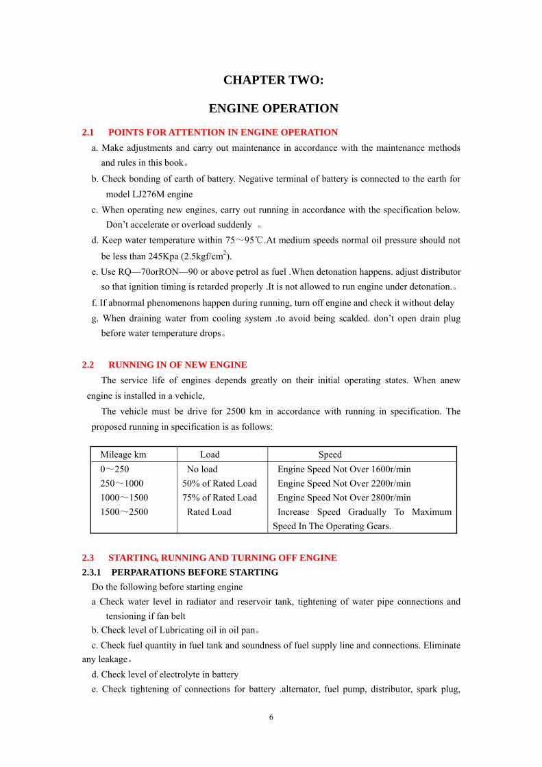
0.75 1.0
18 22
20° 20°
+0.8 +0.8
8.412
Spline Data Of The Output Shaft
Normal modulus Mm
Tooth Number Z
Normal Tooth Pressure
angle
Normal Tooth Stand-off
Measure Normal Line w/k
Measure Span M 20.874
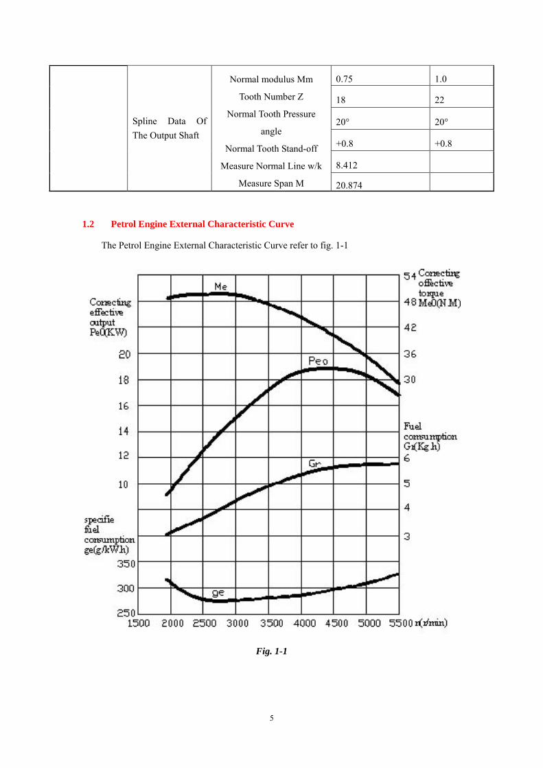
1.2 Petrol Engine External Characteristic Curve
The Petrol Engine External Characteristic Curve refer to fig. 1-1
Fig. 1-1
6
CHAPTER TWO:
ENGINE OPERATION
2.1 POINTS FOR ATTENTION IN ENGINE OPERATION a. Make adjustments and carry out maintenance in accordance with the maintenance methods
and rules in this book。
b. Check bonding of earth of battery. Negative terminal of battery is connected to the earth for model LJ276M engine
c. When operating new engines, carry out running in accordance with the specification below. Don’t accelerate or overload suddenly 。
d. Keep water temperature within 75~95℃.At medium speeds normal oil pressure should not
be less than 245Kpa (2.5kgf/cm2). e. Use RQ—70orRON—90 or above petrol as fuel .When detonation happens. adjust distributor
so that ignition timing is retarded properly .It is not allowed to run engine under detonation.。
f. If abnormal phenomenons happen during running, turn off engine and check it without delay g. When draining water from cooling system .to avoid being scalded. don’t open drain plug
before water temperature drops。
2.2 RUNNING IN OF NEW ENGINE The service life of engines depends greatly on their initial operating states. When anew
engine is installed in a vehicle, The vehicle must be drive for 2500 km in accordance with running in specification. The
proposed running in specification is as follows:
Mileage km Load Speed 0~250 250~1000 1000~1500 1500~2500
No load 50% of Rated Load 75% of Rated Load Rated Load
Engine Speed Not Over 1600r/min Engine Speed Not Over 2200r/min Engine Speed Not Over 2800r/min Increase Speed Gradually To Maximum Speed In The Operating Gears.
2.3 STARTING, RUNNING AND TURNING OFF ENGINE 2.3.1 PERPARATIONS BEFORE STARTING Do the following before starting engine a Check water level in radiator and reservoir tank, tightening of water pipe connections and
tensioning if fan belt b. Check level of Lubricating oil in oil pan。 c. Check fuel quantity in fuel tank and soundness of fuel supply line and connections. Eliminate any leakage。 d. Check level of electrolyte in battery e. Check tightening of connections for battery .alternator, fuel pump, distributor, spark plug,
7
regulator, ignition coils and other electric components. 2.3.2 PROCEDURE FOR STARTING ENGINE A. Set gearshift level to idling position。 B. Move carburetor choke valve near to close position. Then slightly open throttle vale with
starting lever so that rich mixture is obtained. C. Step down clutch pedal. D. Turn ignition switch to start position. Starting time should not be over 5 seconds.
The interval between two adjacent starts should not be less than 20 seconds. E. After starting engine, release ignition switch immediately so that it goes back to ignition
position automatically. At the same time open choke valve partially. With the increase of engine temperature, open choke valve gradually until its fully open position.
2.3.3 STARTING ENGINE AT THE ATMOSPHERIC TEMPERATURE OF LOWER
THAN -5℃ When starting engine at low temperature, in addition to above mentioned checks SE10W/30
OE engine oil for winter use and antifreeze coolant should be used. And engine should be warmed up.
Steps for Engine Warming Up: A. If Antifreeze coolant is not used. Feed hot water of above 90℃ into engine. B. Feed oil of 80℃~90℃ into engine .The oil should be that which has been drained from
engine previously. Draining of oil should be done immediately after engine turn off so that oil is not contaminated.
Rotate crankshaft of warmed up engine by hand several turns so that cylinders suck in small
amount of fuel. Start engine and run it at idling speed for 2~3minutes. Then run engine
from Low load until normal working load .Don’t warm up engine at high speed.
2.3.4 RUNNING ENGINE
A. Running in of an engine in a vehicle must be carried out in accordance with running in
specification. Don’t start or accelerate engine suddenly at high speed. Avoid overloading
engine after running in.
B. It is prohibited to run engine when there is no oil pressure, Oil pressure if too low, abnormal
noises take place, engine is overheated and abnormal vibration happens.
2.3.5 TURNNING OFF ENGINE
It is prohibited to turn off engine at high speed and high load. Before running off engine,
Load must be removed. Then run engine at low speed for 3~5 minutes and turn off ignition
switch. In icy season, if antifreeze coolant and cylinder block immediately after turning off engine.
8
CHAPTER TEREE:
STRUCTURAL CHARCAITERISTICS AND
ADDEMBLY REQUIREMENTS OF ENGINE
3.1 CYLINDERHEAD ASSEMBLY
Cylinder head is made of high strength aluminum alloy. The shape of combustion chamber is
hemispherical. Intake and exhaust runners are distributed on two sides. The overhead camshaft of value
train has very good suitability by three bearing in the cylinder head and driven by timing chain. There are
the advantages of being stable in transmission, compact in structure and low noise.
Rocker arm is made of high strength aluminum alloy with inlaid alloy resists very high
temperature. A sealing unit is used for value stem so that engine oil can not enter combustion
chamber phase angle between the No.1 cylinder and the No.2 cylinder is 360 degrees crank angle.
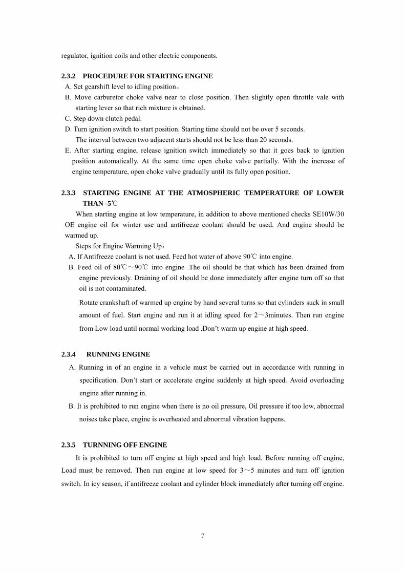
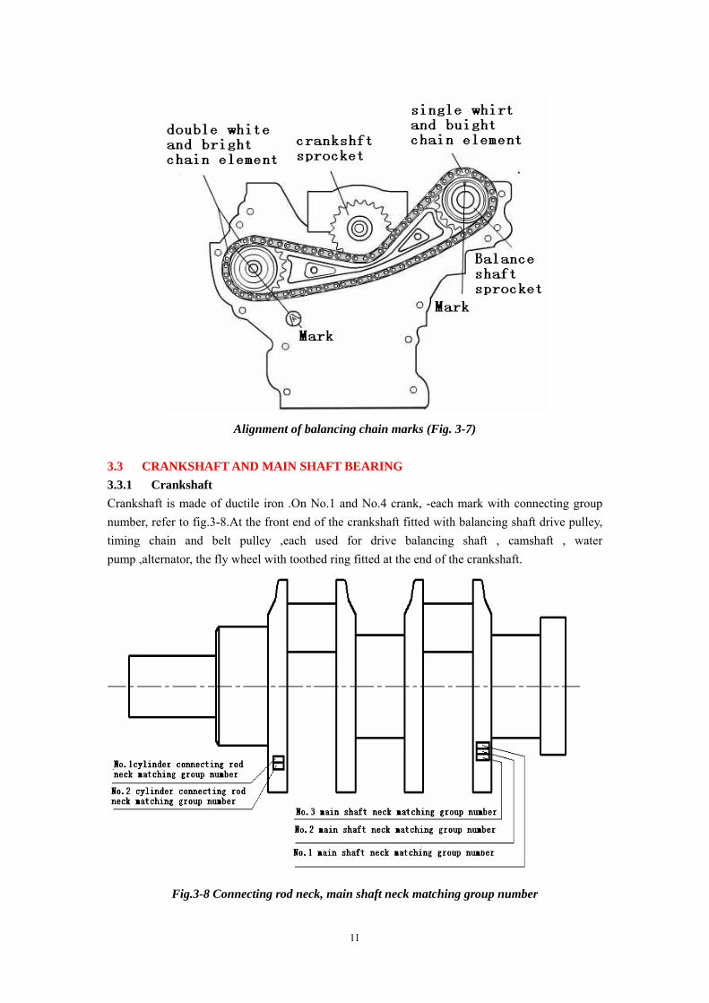
A. Point for installing timing chain Rotate crankshaft to TDC position before installing timing chain. Then align marks on timing sprocket of crankshaft and camshaft sprocket with the white and bright chain element respectively. Now the locating pin in camshaft should be right at the top position (refer to fig.3-1)
B. Locating TDC
Rotate crankshaft to make
pistons in two cylinders go to their
TDC positions in turn. Now the
center mark on boss of crankshaft
pulley should align with the boss of
timing chain cover. Remove cylinder
head cover if the locating pin in
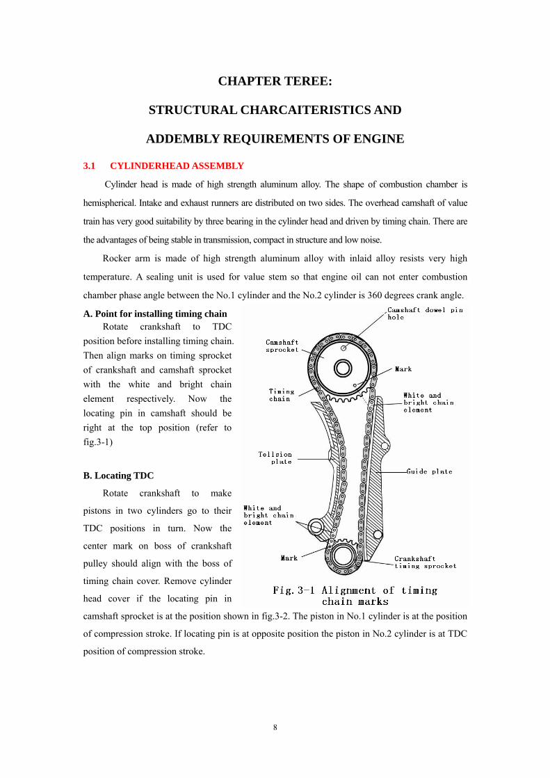
camshaft sprocket is at the position shown in fig.3-2. The piston in No.1 cylinder is at the position
of compression stroke. If locating pin is at opposite position the piston in No.2 cylinder is at TDC
position of compression stroke.
9
Fig.3-2 Fig.3-3
C. Tightening and removing cylinder head bolts.
The tightening order for cylinder head bolts is shown in fig.3-3.tighten bolts uniformly in three
steps. Unfasten are remove bolts in reverse order.
IGHTENING TORQUE requirement NO.1~NO.6 Bolts NO.7Bolt
68.6~73.3N·m(Cold)(7~7.5kgf·m) Tightening torque
75.8~83.4N·m(Hot)(8~8.5kgf·m) 4.9~6.86N·m
(0.5~0.7kgf.m)
3.2 CYLINDERBLOCK ASSEMBLY AND BALANCE CHAIN
Cylinder block is made of alloy cast iron, which has high strength and is wear-resistant .In
order to make operation of engine stable and to reduce vibration. Advanced balancing mechanism
is adopted .The balancing mechanism consists of counter weights and balancing. Shaft which are
ocated on two sides of crankshaft respectively .balancing shaft is driven by a chain.
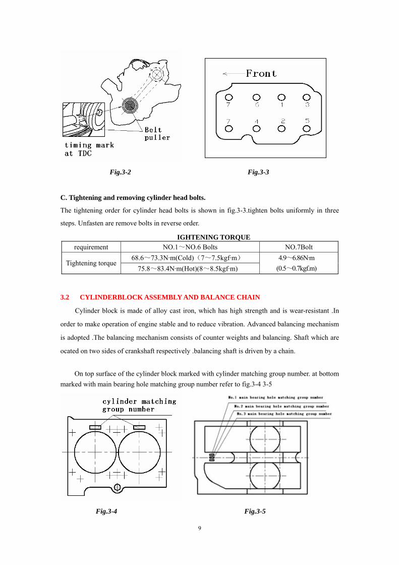
On top surface of the cylinder block marked with cylinder matching group number. at bottom marked with main bearing hole matching group number refer to fig.3-4 3-5
Fig.3-4 Fig.3-5
10
Requirement of matching group is in the table below.
Cylinder matching group Main bearing hole matching group Group number and mark
Cylinder diameterφ76+
0003
Group number and mark
Cylinder diameterφ470
+0.024
1 ≥0 <+0.01 1 ≥0 ≤+0.008 2 ≥+0.01 <+0.02 2 >+0.008 ≤+0.016
3 ≥+0.02 ≤+0.03 3 >+0.016 ≤+0.024
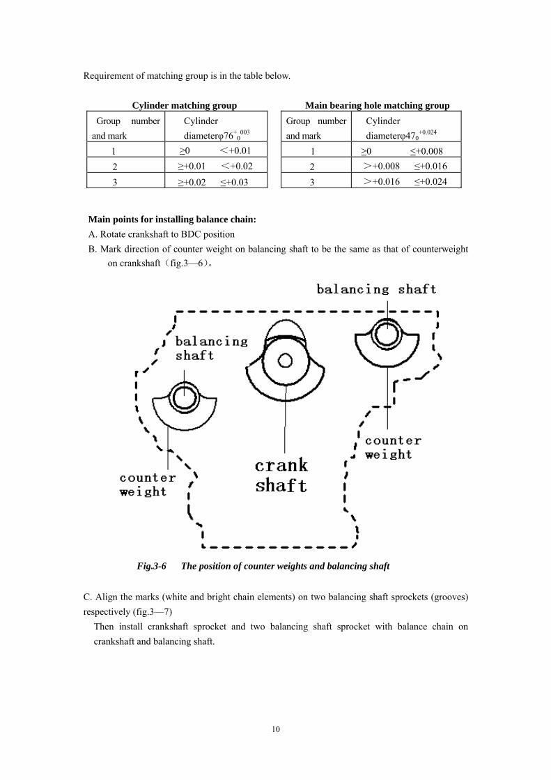
Main points for installing balance chain: A. Rotate crankshaft to BDC position B. Mark direction of counter weight on balancing shaft to be the same as that of counterweight
on crankshaft(fig.3—6)。
Fig.3-6 The position of counter weights and balancing shaft
C. Align the marks (white and bright chain elements) on two balancing shaft sprockets (grooves) respectively (fig.3—7)
Then install crankshaft sprocket and two balancing shaft sprocket with balance chain on crankshaft and balancing shaft.
11
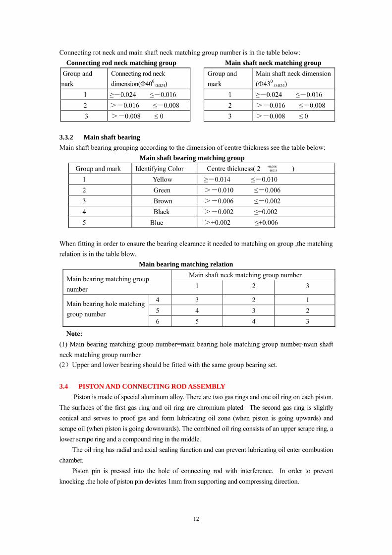
Alignment of balancing chain marks (Fig. 3-7) 3.3 CRANKSHAFT AND MAIN SHAFT BEARING 3.3.1 Crankshaft Crankshaft is made of ductile iron .On No.1 and No.4 crank, -each mark with connecting group number, refer to fig.3-8.At the front end of the crankshaft fitted with balancing shaft drive pulley, timing chain and belt pulley ,each used for drive balancing shaft , camshaft , water pump ,alternator, the fly wheel with toothed ring fitted at the end of the crankshaft.
Fig.3-8 Connecting rod neck, main shaft neck matching group number
12
Connecting rot neck and main shaft neck matching group number is in the table below: Connecting rod neck matching group Main shaft neck matching group
Group and mark
Connecting rod neck dimension(Ф400
-0.024) Group and mark
Main shaft neck dimension (Ф430
-0.024) 1 ≥-0.024 ≤-0.016 1 ≥-0.024 ≤-0.016 2 >-0.016 ≤-0.008 2 >-0.016 ≤-0.008 3 >-0.008 ≤ 0
3 >-0.008 ≤ 0 3.3.2 Main shaft bearing Main shaft bearing grouping according to the dimension of centre thickness see the table below:
Main shaft bearing matching group Group and mark Identifying Color Centre thickness( 2 +0.006
-0.014 ) 1 Yellow ≥-0.014 ≤-0.010 2 Green >-0.010 ≤-0.006 3 Brown >-0.006 ≤-0.002 4 Black >-0.002 ≤+0.002 5 Blue >+0.002 ≤+0.006
When fitting in order to ensure the bearing clearance it needed to matching on group ,the matching relation is in the table blow. Main bearing matching relation
Main shaft neck matching group number Main bearing matching group number 1 2 3
4 3 2 1 5 4 3 2
Main bearing hole matching group number
6 5 4 3
Note: (1) Main bearing matching group number=main bearing hole matching group number-main shaft neck matching group number (2)Upper and lower bearing should be fitted with the same group bearing set. 3.4 PISTON AND CONNECTING ROD ASSEMBLY
Piston is made of special aluminum alloy. There are two gas rings and one oil ring on each piston. The surfaces of the first gas ring and oil ring are chromium plated The second gas ring is slightly conical and serves to proof gas and form lubricating oil zone (when piston is going upwards) and scrape oil (when piston is going downwards). The combined oil ring consists of an upper scrape ring, a lower scrape ring and a compound ring in the middle. The oil ring has radial and axial sealing function and can prevent lubricating oil enter combustion chamber. Piston pin is pressed into the hole of connecting rod with interference. In order to prevent knocking .the hole of piston pin deviates 1mm from supporting and compressing direction.
13
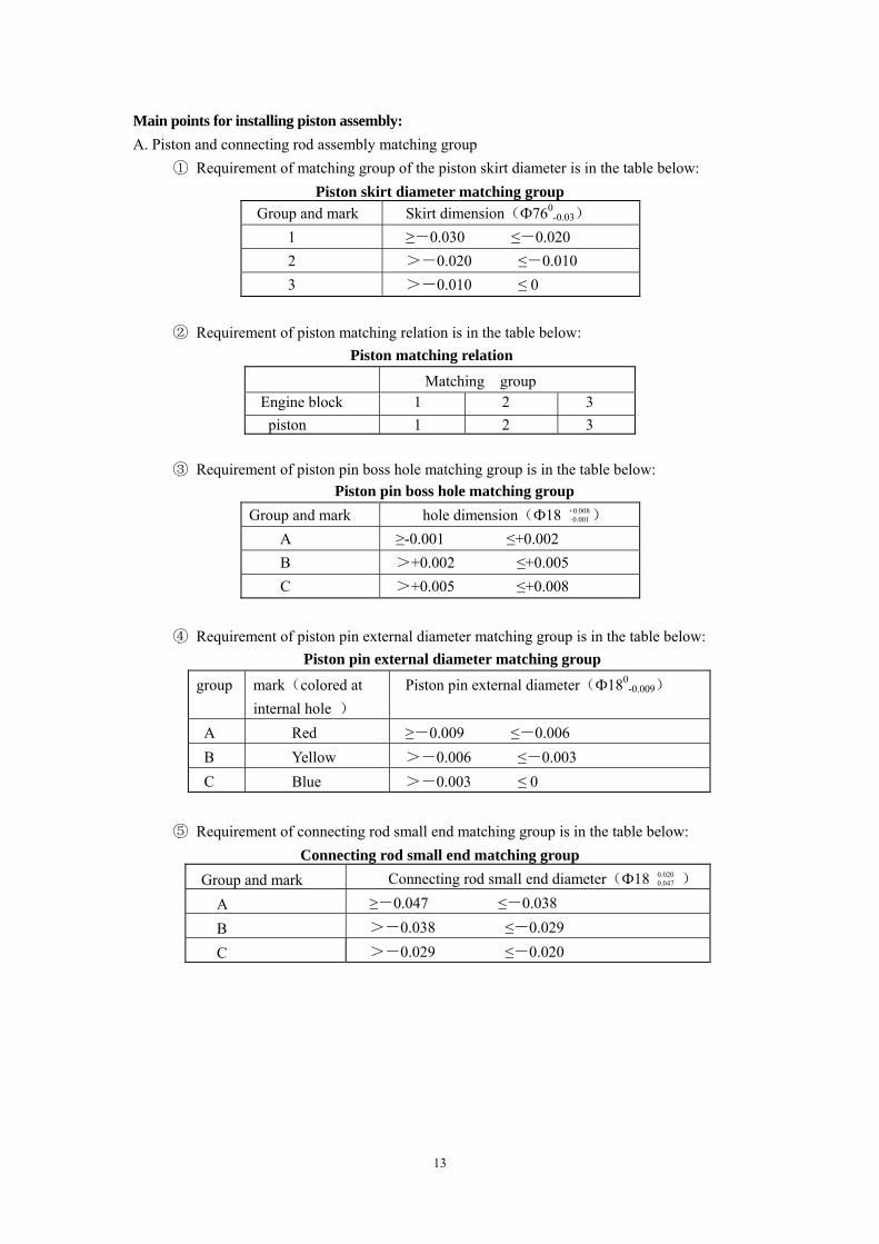
Main points for installing piston assembly: A. Piston and connecting rod assembly matching group
① Requirement of matching group of the piston skirt diameter is in the table below: Piston skirt diameter matching group
Group and mark Skirt dimension(Ф760-0.03)
1 ≥-0.030 ≤-0.020 2 >-0.020 ≤-0.010 3 >-0.010 ≤ 0
② Requirement of piston matching relation is in the table below:
Piston matching relation Matching group Engine block 1 2 3 piston 1 2 3
③ Requirement of piston pin boss hole matching group is in the table below:
Piston pin boss hole matching group Group and mark hole dimension(Ф18 +0.008
–0.001) A ≥-0.001 ≤+0.002 B >+0.002 ≤+0.005 C >+0.005 ≤+0.008
④ Requirement of piston pin external diameter matching group is in the table below:
Piston pin external diameter matching group
group mark(colored at internal hole )
Piston pin external diameter(Ф180-0.009)
A Red ≥-0.009 ≤-0.006 B Yellow >-0.006 ≤-0.003 C Blue >-0.003 ≤ 0
⑤ Requirement of connecting rod small end matching group is in the table below:
Connecting rod small end matching group Group and mark Connecting rod small end diameter(Ф18 0.020
0.047 ) A ≥-0.047 ≤-0.038
B >-0.038 ≤-0.029
C >-0.029 ≤-0.020
14
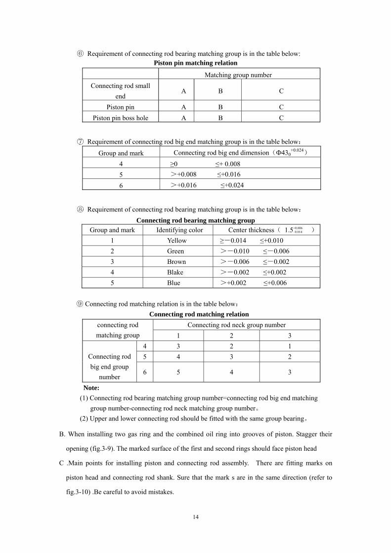
⑥ Requirement of connecting rod bearing matching group is in the table below: Piston pin matching relation
Matching group number Connecting rod small
end A B C
Piston pin A B C Piston pin boss hole A B C
⑦ Requirement of connecting rod big end matching group is in the table below:
Group and mark Connecting rod big end dimension(Ф430+0.024)
4 ≥0 ≤+ 0.008 5 >+0.008 ≤+0.016
6 >+0.016 ≤+0.024
⑧ Requirement of connecting rod bearing matching group is in the table below: Connecting rod bearing matching group
Group and mark Identifying color Center thickness( 1.5+0.006 –0.014 )
1 Yellow ≥-0.014 ≤+0.010 2 Green >-0.010 ≤-0.006 3 Brown >-0.006 ≤-0.002 4 Blake >-0.002 ≤+0.002 5 Blue >+0.002 ≤+0.006
⑨ Connecting rod matching relation is in the table below: Connecting rod matching relation
Connecting rod neck group number connecting rod matching group 1 2 3
4 3 2 1 5 4 3 2
Connecting rod big end group
number 6 5 4 3
Note: (1) Connecting rod bearing matching group number=connecting rod big end matching group number-connecting rod neck matching group number。 (2) Upper and lower connecting rod should be fitted with the same group bearing。
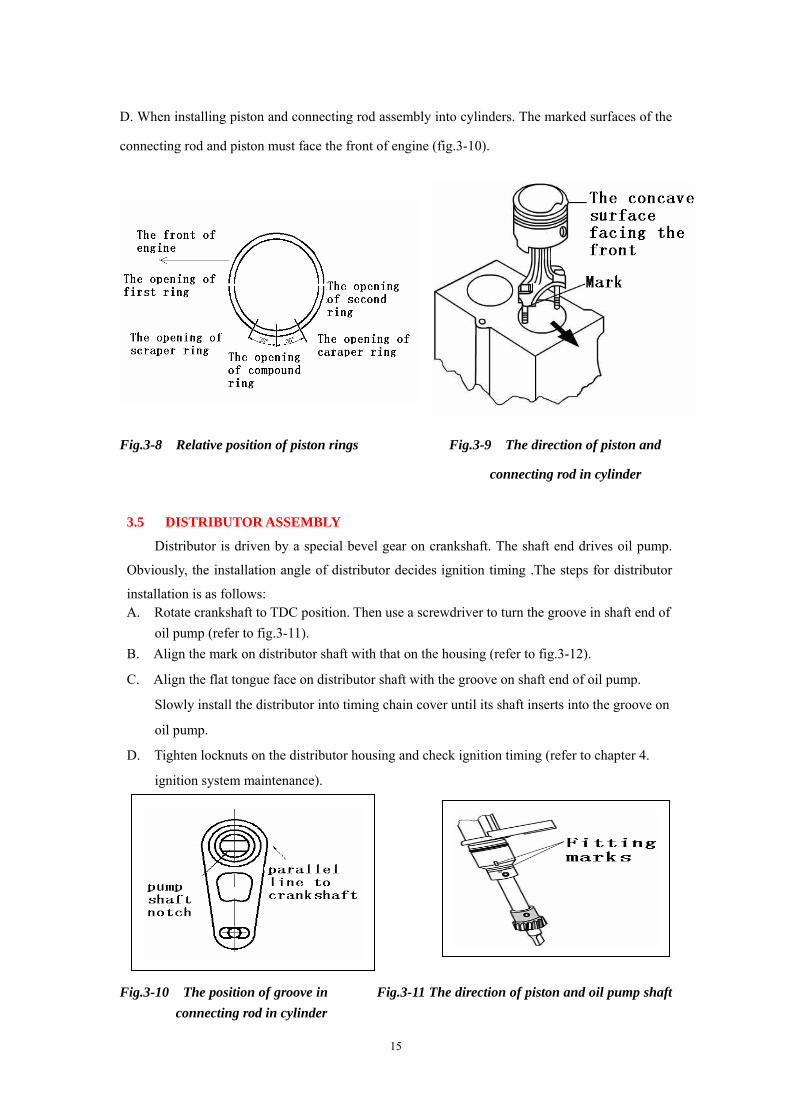
B. When installing two gas ring and the combined oil ring into grooves of piston. Stagger their
opening (fig.3-9). The marked surface of the first and second rings should face piston head
C .Main points for installing piston and connecting rod assembly. There are fitting marks on
piston head and connecting rod shank. Sure that the mark s are in the same direction (refer to
fig.3-10) .Be careful to avoid mistakes.
15
D. When installing piston and connecting rod assembly into cylinders. The marked surfaces of the
connecting rod and piston must face the front of engine (fig.3-10).
Fig.3-8 Relative position of piston rings Fig.3-9 The direction of piston and
connecting rod in cylinder
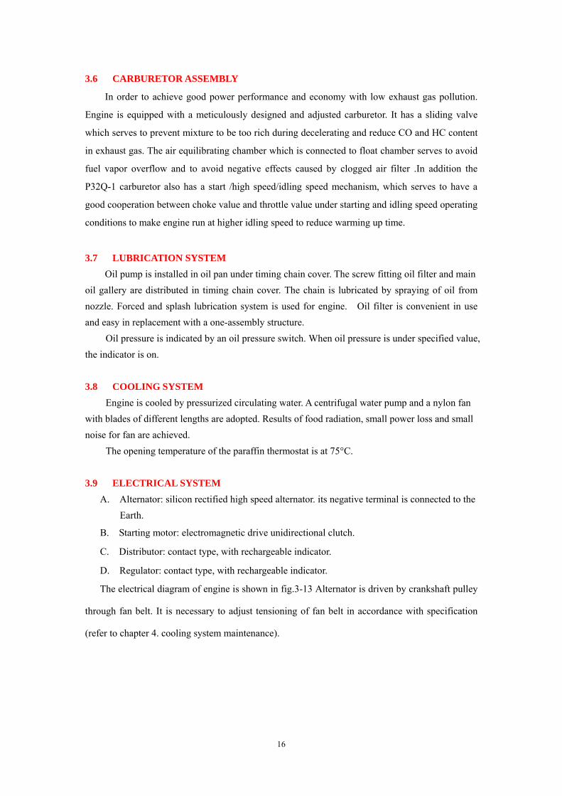
3.5 DISTRIBUTOR ASSEMBLY
Distributor is driven by a special bevel gear on crankshaft. The shaft end drives oil pump.
Obviously, the installation angle of distributor decides ignition timing .The steps for distributor
installation is as follows: A. Rotate crankshaft to TDC position. Then use a screwdriver to turn the groove in shaft end of oil pump (refer to fig.3-11). B. Align the mark on distributor shaft with that on the housing (refer to fig.3-12).
C. Align the flat tongue face on distributor shaft with the groove on shaft end of oil pump.
Slowly install the distributor into timing chain cover until its shaft inserts into the groove on
oil pump.
D. Tighten locknuts on the distributor housing and check ignition timing (refer to chapter 4.
ignition system maintenance).
Gbbcxdffggfdggf
Fig.3-10 The position of groove in Fig.3-11 The direction of piston and oil pump shaft connecting rod in cylinder
16
3.6 CARBURETOR ASSEMBLY
In order to achieve good power performance and economy with low exhaust gas pollution.
Engine is equipped with a meticulously designed and adjusted carburetor. It has a sliding valve
which serves to prevent mixture to be too rich during decelerating and reduce CO and HC content
in exhaust gas. The air equilibrating chamber which is connected to float chamber serves to avoid
fuel vapor overflow and to avoid negative effects caused by clogged air filter .In addition the
P32Q-1 carburetor also has a start /high speed/idling speed mechanism, which serves to have a
good cooperation between choke value and throttle value under starting and idling speed operating
conditions to make engine run at higher idling speed to reduce warming up time.
3.7 LUBRICATION SYSTEM Oil pump is installed in oil pan under timing chain cover. The screw fitting oil filter and main
oil gallery are distributed in timing chain cover. The chain is lubricated by spraying of oil from nozzle. Forced and splash lubrication system is used for engine. Oil filter is convenient in use and easy in replacement with a one-assembly structure.
Oil pressure is indicated by an oil pressure switch. When oil pressure is under specified value, the indicator is on.
3.8 COOLING SYSTEM
Engine is cooled by pressurized circulating water. A centrifugal water pump and a nylon fan with blades of different lengths are adopted. Results of food radiation, small power loss and small noise for fan are achieved.
The opening temperature of the paraffin thermostat is at 75°C.
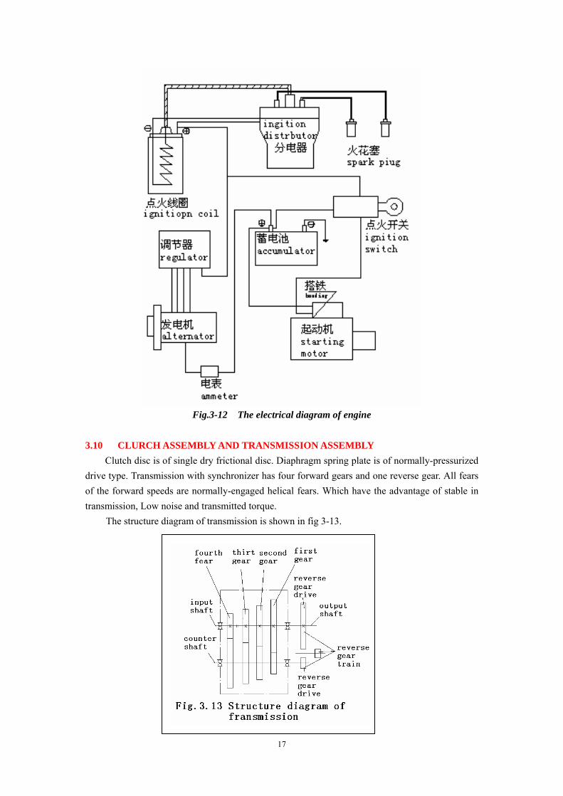
3.9 ELECTRICAL SYSTEM A. Alternator: silicon rectified high speed alternator. its negative terminal is connected to the Earth.
B. Starting motor: electromagnetic drive unidirectional clutch.
C. Distributor: contact type, with rechargeable indicator.
D. Regulator: contact type, with rechargeable indicator.
The electrical diagram of engine is shown in fig.3-13 Alternator is driven by crankshaft pulley
through fan belt. It is necessary to adjust tensioning of fan belt in accordance with specification
(refer to chapter 4. cooling system maintenance).
17
Fig.3-12 The electrical diagram of engine
3.10 CLURCH ASSEMBLY AND TRANSMISSION ASSEMBLY
Clutch disc is of single dry frictional disc. Diaphragm spring plate is of normally-pressurized drive type. Transmission with synchronizer has four forward gears and one reverse gear. All fears of the forward speeds are normally-engaged helical fears. Which have the advantage of stable in transmission, Low noise and transmitted torque.
The structure diagram of transmission is shown in fig 3-13.
18
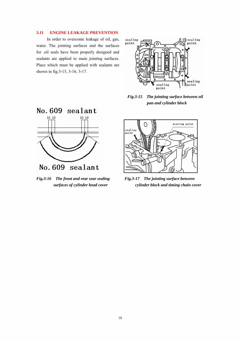
3.11 ENGINE LEAKAGE PREVENTION In order to overcome leakage of oil, gas, water. The jointing surfaces and the surfaces for .oil seals have been properly designed and sealants are applied to main jointing surfaces. Place which must be applied with sealants are shown in fig.3-15, 3-16, 3-17.
Fig.3-15 The jointing surface between oil pan and cylinder block
Fig.3-16 The front and rear sear sealing Fig.3-17 The jointing surface between surfaces of cylinder head cover cylinder block and timing chain cover
19
CHAPTER FOUR :
ENGIN MAINTENANCE 4.1 ENGINE MAINTENANCE CYCLE 4.1.1 DAILY MAINTENANCE A. Check the levels of fuel, Cooling water and oil. Replenish if necessary. B. Check jointing surfaces for leakage of oil and water.
C. Check high-tension cables for looseness. D. Check electrolyte level in battery. Refill distilled water if the level is not high enough. E. Carefully listen to the sound of engine running at idling speed after starting. Observe the
functioning of different instruments. 4.1.2 MAINTENANCE AFTER FIRST 1000KM
A. Carry out the maintenance mentioned in daily maintenance. B. Check the tightening of bolts between engines and bracket and exhaust manifold between engine and air filter.
C. Check the tightening of cylinder head bolts. If there is looseness, retighten in accordance with the order in the instruction.
D. check valve clearances, Adjust if necessary。 E. Check the tensioning of fan belt. Adjust if necessary F. Check idling speed and ignition timing. G. Check gravity of electrolyte in battery or voltage of battery. H. Check connections of alternator, regulator, Ignition coils and spark plug for looseness. I. Check and adjust the free travel of clutch pedal. 4.1.3 MAINTENANCE AFTER RORST 2500 KM A. Carry out the maintenance mentioned in daily maintenance. B. Check the wear and tensioning of fan belt. Replace or adjust if necessary.
C. Clean the electrodes of spark plug. Adjust electrode gap if necessary. D. Replace the paper element of air filter. E. Change oil of engine and replace oil filter. F. Start engine and check for any abnormal noises from power train under no load. G. Operate clutch. Clutching off should be complete and clutching on should be smooth. It
should be smooth to shift gears of transmission. H. Replace lubricating oil of transmission. 4.1.4 MAINTENANCE ECERY 5000 KM
A. Carry out the maintenance in point 4.1.3(refill lubricating oil instead of replacing lubricating oil.)
B. Clean fuel tank, fuel line and carburetor barrel. C. Check battery for cracks or leakages of electricity.
20
D. Check functioning of regulator.
4.1.5 MAINTENANCE EVERY 10000 KM
A. Carry out the maintenance in point 4.1.4
B. Replace air filter element.
C. Replace oil filter and change engine oil.
D. Remove cylinder head and clean carbon deposit on the surface of combustion chamber and
on piston head. Clean the dirt inside intake and exhaust system.
E. Remove and clean alternator and starting motor. Replace the grease in their bearings.
F. Check the functioning of throttle operating wire and carburetor shaft.
G Check the contamination of lubrication oil in transmission. Replace if necessary. H. Replace the antifreeze coolant in the cooling system.
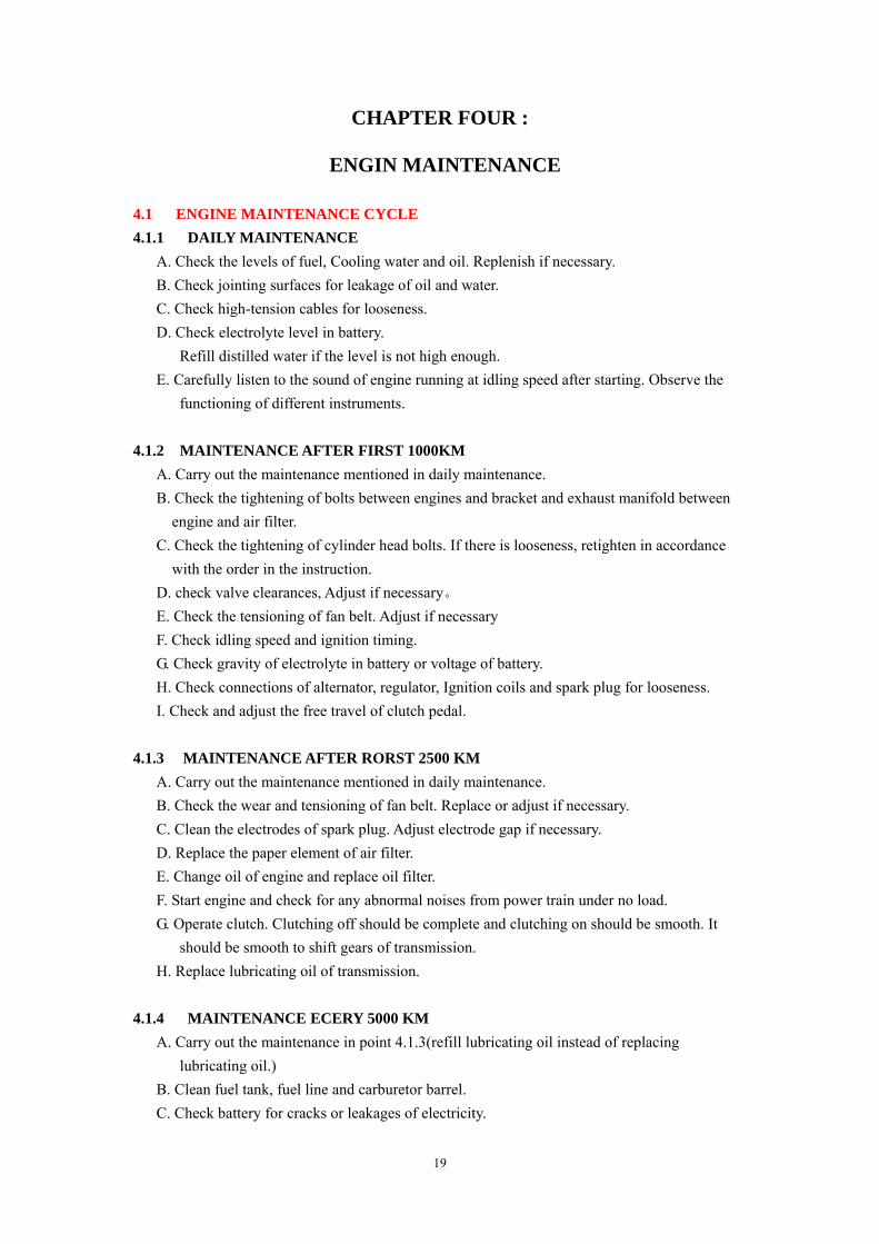
4.2 PONINTS OF ATTENTION FOR ENGINE MAINTENANCE 4.2.1 LUBRICATION SYSTEM MAINTENANCE A. Measurement of oil level
The quantity of oil in oil pan is measured by a dipstick on the right side of engine. To check the oil level, turn off engine and wait until oil surface is quiet (about after 5 minutes),take out the dipstick and remove oil trace with a clean cloth .then insert the dipstick and take out again. The oil level must be between the upper and lower lines (refer to fig.4-1) B. Changing oil
Proper selection and change of oil in accordance with the maintenance cycle are very important to ensure good operation and service life of engine. Users should select oils in accordance with instruction strictly. Don’t mix and use oils of different brands.
Before replacing oil, drain oil from oil pan when engine is hot. If there are large amount of impurities inside oil pan, the engine lubrication system must be cleaned with light spindle oil, Kerosene or petrol are prohibited to be used for cleaning. Filling 3 liters of light spindle oil through oil filler port, Start engine with starting motor to idling speed for 2~3 times for one minute a time, drain spindle oil quickly and fill oil into engine in accordance with specification.
Every time after change of oil .run engine at idle speed for 3~5 minutes to ensure that lubrication system obtains enough oil .
Replace transmission lubricating oil when lubricating oil is still warm. Open drain plug on the hole of hexagon-headed bolt on the right side of the housing until oil goes up to lower edge of the hole.
21
C. For lubricating distributor cam and breaker contacts. drip 1~2 drops of oil on felt periodically.
4.2.2 COOLING SYSTEM MAINTENANCE
A. To ensure normal operation of engine.
There must be enough coolant. Therefore,
it is necessary to check coolant and
replenish clean soft water every time
before going out with a vehicle. It is
prohibited to use hard alkaline water with
many minerals. In winter, antifreeze must
be used. Generally speaking, the freezing
point of the selected antifreeze must be
5℃ lower than the lowest temperature of
the area where engine is used. If
antifreeze is not used, drain cooling water
from radiator and cylinder block after
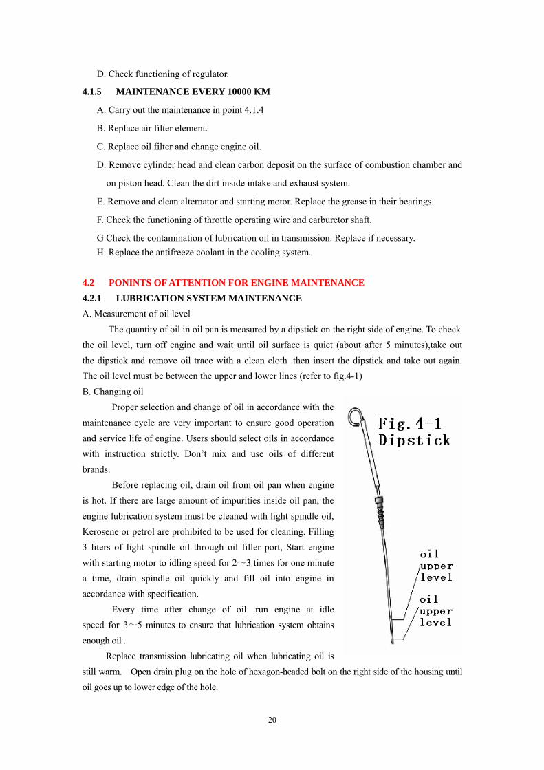
turn off of engine without delay. B. It is necessary to check tensioning of fan belt regularly.
Adjust tensioning if necessary (refer to fig4-2). The appearance of fan must be good. The excessively worn belt must be replaced without delay.
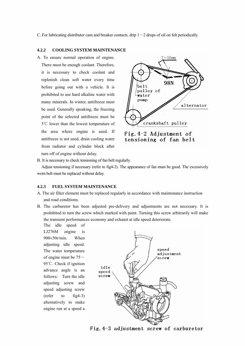
4.2.3 FUEL SYSTEM MAINTENANCE A. The air filter element must be replaced regularly in accordance with maintenance instruction and road conditions. B. The carburetor has been adjusted pre-delivery and adjustments are not necessary. It is
prohibited to turn the screw which marked with paint. Turning this screw arbitrarily will make the transient performances economy and exhaust at idle speed deteriorate. The idle speed of LJ276M engine is 900±50r/min. When adjusting idle speed. The water temperature of engine must be 75~95℃. Check if ignition advance angle is an follows: Turn the idle adjusting screw and speed adjusting screw (refer to fig4-3) alternatively to make engine run at a speed a
22
bit higher than idle speed. Then turning idle adjusting screw until the engine speed is lower than idle speed and turn back for 1/4 turns.
C.The fuel level in the float chamber must be
within the Ф3 circle in the centre of fuel
mirror. When the f fuel level is too high or too
low, it can be be regulated by changing the
thickness of the spaces of float needle valve
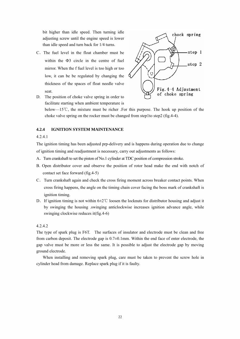
seat. D. The position of choke valve spring in order to
facilitate starting when ambient temperature is below—15℃, the mixture must be richer .For this purpose. The hook up position of the choke valve spring on the rocker must be changed from step1to step2 (fig.4-4).
4.2.4 IGNITION SYSTEM MAINTENANCE
4.2.4.1
The ignition timing has been adjusted prp-delivery and is happens during operation due to change
of ignition timing and readjustment is necessary, carry out adjustments as follows:
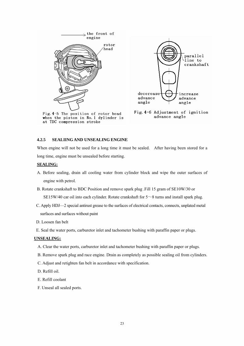
A.Turn crankshaft to set the piston of No.1 cylinder at TDC position of compression stroke.
B. Open distributor cover and observe the position of rotor head make the end with notch of
contact set face forward (fig.4-5)
C. Turn crankshaft again and check the cross firing moment across breaker contact points. When
cross firing happens, the angle on the timing chain cover facing the boss mark of crankshaft is
ignition timing. D. If ignition timing is not within 6±2℃ loosen the locknuts for distributor housing and adjust it
by swinging the housing .swinging anticlockwise increases ignition advance angle, while swinging clockwise reduces it(fig.4-6)
4.2.4.2 The type of spark plug is F6T. The surfaces of insulator and electrode must be clean and free from carbon deposit. The electrode gap is 0.7±0.1mm. Within the end face of enter electrode, the gap valve must be more or less the same. It is possible to adjust the electrode gap by moving ground electrode.
When installing and removing spark plug, care must be taken to prevent the screw hole in cylinder head from damage. Replace spark plug if it is faulty.
23
4.2.5 SEALIING AND UNSEALING ENGINE
When engine will not be used for a long time it must be sealed. After having been stored for a
long time, engine must be unsealed before starting.
SEALING:
A. Before sealing, drain all cooling water from cylinder block and wipe the outer surfaces of
engine with petrol.
B. Rotate crankshaft to BDC Position and remove spark plug .Fill 15 gram of SE10W/30 or
SE15W/40 car oil into each cylinder. Rotate crankshaft for 5~8 turns and install spark plug.
C. Apply HDJ—2 special antirust grease to the surfaces of electrical contacts, connects, unplated metal
surfaces and surfaces without paint
D. Loosen fan belt
E. Seal the water ports, carburetor inlet and tachometer bushing with paraffin paper or plugs.
UNSEALING:
A. Clear the water ports, carburetor inlet and tachometer bushing with paraffin paper or plugs.
B. Remove spark plug and race engine. Drain as completely as possible sealing oil from cylinders.
C. Adjust and retighten fan belt in accordance with specification.
D. Refill oil.
E. Refill coolant
F. Unseal all sealed ports.
24
CHAPTER FIVE:
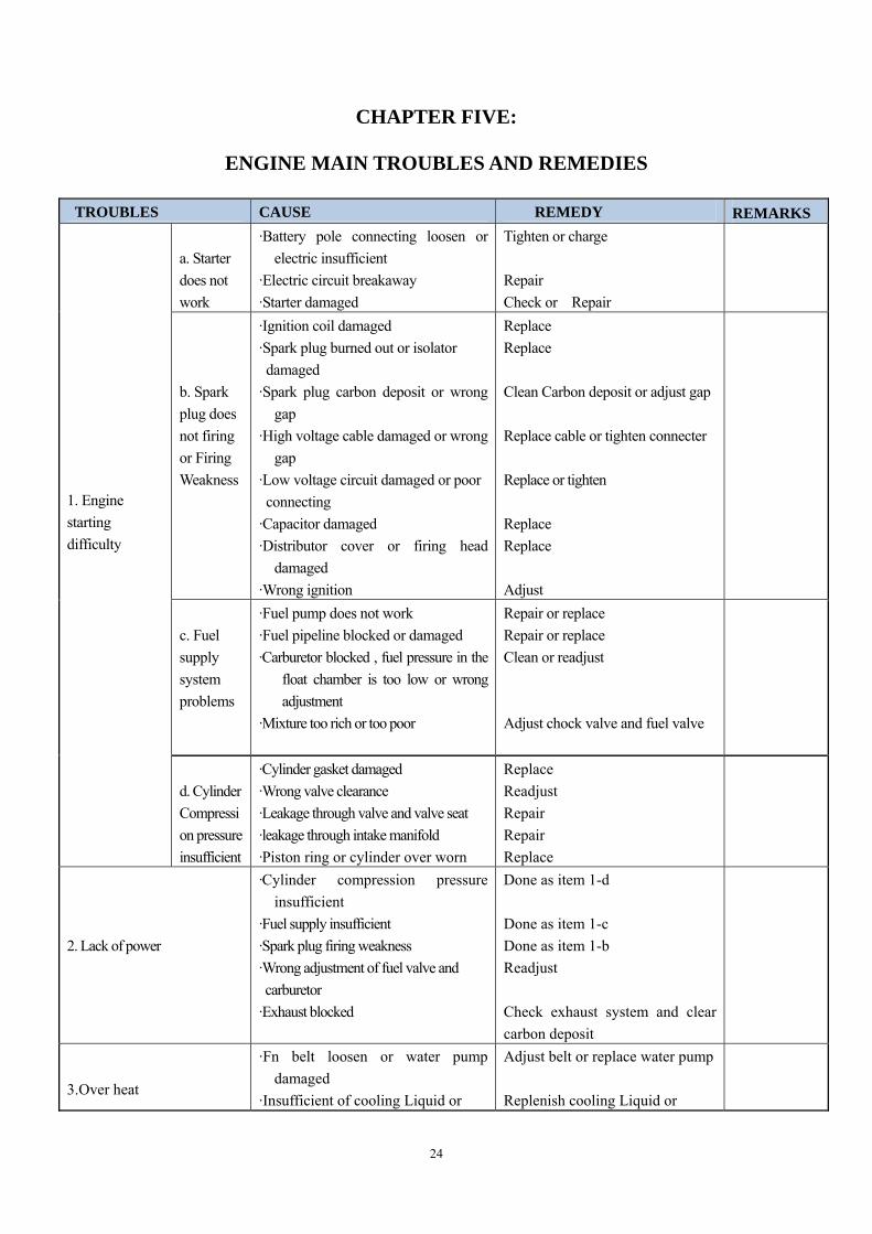
ENGINE MAIN TROUBLES AND REMEDIES
TROUBLES CAUSE REMEDY REMARKS a. Starter does not work
·Battery pole connecting loosen or electric insufficient
·Electric circuit breakaway ·Starter damaged
Tighten or charge Repair Check or Repair
b. Spark plug does not firing or Firing Weakness
·Ignition coil damaged ·Spark plug burned out or isolator damaged ·Spark plug carbon deposit or wrong
gap ·High voltage cable damaged or wrong
gap ·Low voltage circuit damaged or poor connecting ·Capacitor damaged ·Distributor cover or firing head
damaged ·Wrong ignition
Replace Replace Clean Carbon deposit or adjust gap Replace cable or tighten connecter Replace or tighten Replace Replace Adjust
c. Fuel supply system problems
·Fuel pump does not work ·Fuel pipeline blocked or damaged ·Carburetor blocked , fuel pressure in the
float chamber is too low or wrong adjustment
·Mixture too rich or too poor
Repair or replace Repair or replace Clean or readjust Adjust chock valve and fuel valve
1. Engine starting difficulty
d. Cylinder Compression pressure insufficient
·Cylinder gasket damaged ·Wrong valve clearance ·Leakage through valve and valve seat ·leakage through intake manifold ·Piston ring or cylinder over worn
Replace Readjust Repair Repair Replace
2. Lack of power
·Cylinder compression pressure insufficient
·Fuel supply insufficient ·Spark plug firing weakness ·Wrong adjustment of fuel valve and carburetor ·Exhaust blocked
Done as item 1-d Done as item 1-c Done as item 1-b Readjust Check exhaust system and clear carbon deposit
3.Over heat
·Fn belt loosen or water pump damaged
·Insufficient of cooling Liquid or
Adjust belt or replace water pump Replenish cooling Liquid or
25
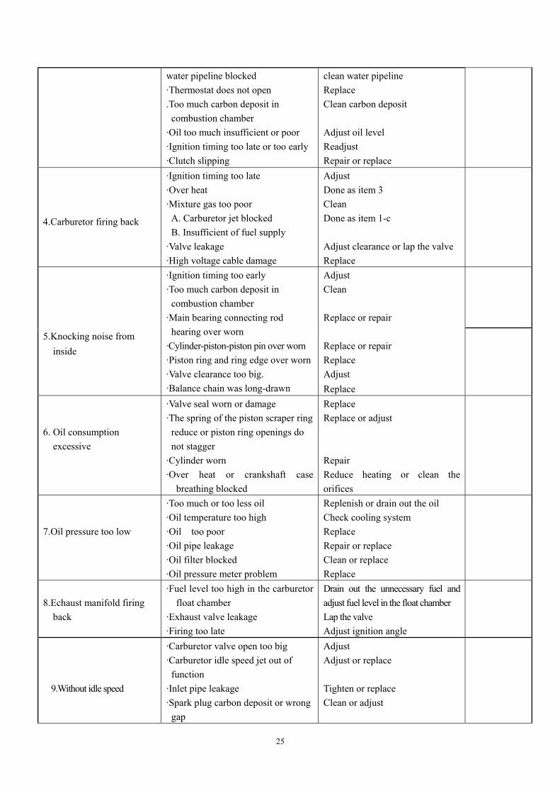
water pipeline blocked ·Thermostat does not open .Too much carbon deposit in combustion chamber ·Oil too much insufficient or poor ·Ignition timing too late or too early ·Clutch slipping
clean water pipeline Replace Clean carbon deposit Adjust oil level Readjust Repair or replace
4.Carburetor firing back
·Ignition timing too late ·Over heat ·Mixture gas too poor A. Carburetor jet blocked B. Insufficient of fuel supply ·Valve leakage ·High voltage cable damage
Adjust Done as item 3 Clean Done as item 1-c Adjust clearance or lap the valve Replace
5.Knocking noise from
inside
·Ignition timing too early ·Too much carbon deposit in combustion chamber ·Main bearing connecting rod hearing over worn ·Cylinder-piston-piston pin over worn ·Piston ring and ring edge over worn ·Valve clearance too big. ·Balance chain was long-drawn
Adjust Clean Replace or repair Replace or repair Replace Adjust Replace
6. Oil consumption
excessive
·Valve seal worn or damage ·The spring of the piston scraper ring reduce or piston ring openings do not stagger ·Cylinder worn ·Over heat or crankshaft case
breathing blocked
Replace Replace or adjust Repair Reduce heating or clean the orifices
7.Oil pressure too low
·Too much or too less oil ·Oil temperature too high ·Oil too poor ·Oil pipe leakage ·Oil filter blocked ·Oil pressure meter problem
Replenish or drain out the oil Check cooling system Replace Repair or replace Clean or replace Replace
8.Echaust manifold firing
back
·Fuel level too high in the carburetor float chamber
·Exhaust valve leakage ·Firing too late
Drain out the unnecessary fuel and adjust fuel level in the float chamber Lap the valve Adjust ignition angle
9.Without idle speed
·Carburetor valve open too big ·Carburetor idle speed jet out of function ·Inlet pipe leakage ·Spark plug carbon deposit or wrong gap
Adjust Adjust or replace Tighten or replace Clean or adjust
26
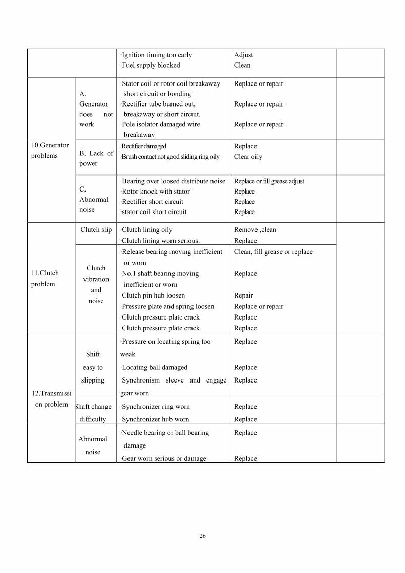
·Ignition timing too early ·Fuel supply blocked
Adjust Clean
A. Generator does not work
·Stator coil or rotor coil breakaway short circuit or bonding ·Rectifier tube burned out, breakaway or short circuit. ·Pole isolator damaged wire breakaway
Replace or repair Replace or repair Replace or repair
B. Lack of power
.Rectifier damaged ·Brush contact not good sliding ring oily
Replace Clear oily
10.Generator problems
C. Abnormal noise
·Bearing over loosed distribute noise ·Rotor knock with stator ·Rectifier short circuit ·stator coil short circuit
Replace or fill grease adjust Replace Replace Replace
Clutch slip
·Clutch lining oily ·Clutch lining worn serious.
Remove ,clean Replace
11.Clutch problem
Clutch
vibration and
noise
·Release bearing moving inefficient or worn ·No.1 shaft bearing moving inefficient or worn ·Clutch pin hub loosen ·Pressure plate and spring loosen ·Clutch pressure plate crack ·Clutch pressure plate crack
Clean, fill grease or replace Replace Repair Replace or repair Replace Replace
Shift
easy to
slipping
·Pressure on locating spring too
weak
·Locating ball damaged
·Synchronism sleeve and engage
gear worn
Replace
Replace
Replace
Shaft change
difficulty
·Synchronizer ring worn
·Synchronizer hub worn
Replace
Replace
12.Transmissi
on problem
Abnormal
noise
·Needle bearing or ball bearing
damage
·Gear worn serious or damage
Replace
Replace
27
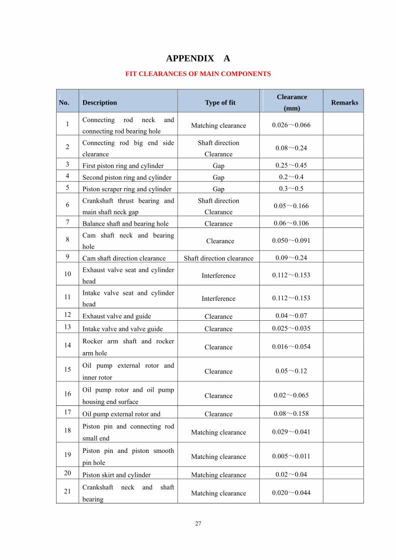
APPENDIX A FIT CLEARANCES OF MAIN COMPONENTS
No. Description Type of fit Clearance
(mm) Remarks
1 Connecting rod neck and connecting rod bearing hole
Matching clearance 0.026~0.066
2 Connecting rod big end side clearance
Shaft direction Clearance
0.08~0.24
3 First piston ring and cylinder Gap 0.25~0.45 4 Second piston ring and cylinder Gap 0.2~0.4 5 Piston scraper ring and cylinder Gap 0.3~0.5
6 Crankshaft thrust bearing and main shaft neck gap
Shaft direction Clearance
0.05~0.166
7 Balance shaft and bearing hole Clearance 0.06~0.106
8 Cam shaft neck and bearing hole
Clearance 0.050~0.091
9 Cam shaft direction clearance Shaft direction clearance 0.09~0.24
10 Exhaust valve seat and cylinder head
Interference 0.112~0.153
11 Intake valve seat and cylinder head
Interference 0.112~0.153
12 Exhaust valve and guide Clearance 0.04~0.07 13 Intake valve and valve guide Clearance 0.025~0.035
14 Rocker arm shaft and rocker
arm hole Clearance 0.016~0.054
15 Oil pump external rotor and
inner rotor Clearance 0.05~0.12
16 Oil pump rotor and oil pump
housing end surface Clearance 0.02~0.065
17 Oil pump external rotor and Clearance 0.08~0.158
18 Piston pin and connecting rod
small end Matching clearance 0.029~0.041
19 Piston pin and piston smooth
pin hole Matching clearance 0.005~0.011
20 Piston skirt and cylinder Matching clearance 0.02~0.04
21 Crankshaft neck and shaft
bearing Matching clearance 0.020~0.044
28
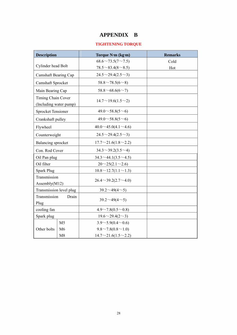
APPENDIX B TIGHTENING TORQUE
Description Torque N·m (kg·m) Remarks
Cylinder head Bolt 68.6~73.5(7~7.5) 78.5~83.4(8~8.5)
Cold Hot
Camshaft Bearing Cap 24.5~29.4(2.5~3)
Camshaft Sprocket 58.8~78.5(6~8)
Main Bearing Cap 58.8~68.6(6~7)
Timing Chain Cover (Including water pump)
14.7~19.6(1.5~2)
Sprocket Tensioner 49.0~58.8(5~6)
Crankshaft pulley 49.0~58.8(5~6)
Flywheel 40.0~45.0(4.1~4.6)
Counterweight 24.5~29.4(2.5~3)
Balancing sprocket 17.7~21.6(1.8~2.2)
Con. Rod Cover 34.3~39.2(3.5~4)
Oil Pan plug 34.3~44.1(3.5~4.5) Oil filter 20~25(2.1~2.6) Spark Plug 10.8~12.7(1.1~1.3) Transmission Assembly(M12)
26.4~39.2(2.7~4.0)
Transmission level plug 39.2~49(4~5) Transmission Drain Plug
39.2~49(4~5)
cooling fan 4.9~7.8(0.5~0.8) Spark plug 19.6~29.4(2~3) Other bolts
M5 M6 M8
3.9~5.9(0.4~0.6) 9.8~7.8(0.8~1.0)
14.7~21.6(1.5~2.2)
29
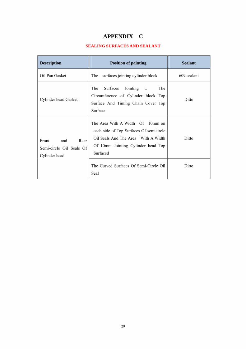
APPENDIX C SEALING SURFACES AND SEALANT
Description Position of painting Sealant
Oil Pan Gasket The surfaces jointing cylinder block 609 sealant
Cylinder head Gasket
The Surfaces Jointing t. The
Circumference of Cylinder block Top
Surface And Timing Chain Cover Top
Surface.
Ditto
The Area With A Width Of 10mm on
each side of Top Surfaces Of semicircle
Oil Seals And The Area With A Width
Of 10mm Jointing Cylinder head Top
Surfaced
Ditto Front and Rear
Semi-circle Oil Seals Of
Cylinder head
The Curved Surfaces Of Semi-Circle Oil
Seal
Ditto