Embed Size (px)
Citation preview
LLETIN NO 4 TYPE VIBRATORY R
CONSTRUCTION MANUFA CTi Track Mixers'
m 7 Cre te': illo rt :arid
cad I iavets readers
Floats Spi-a); Cato ac SOTrarde Planer
MACHINERYMAC ,HIN CERY SECTION, MILWAUKEE, WISCONSIN 5 3201
zn-es :
ester.::
Conveyors Ronda Jan
antra Pry Aotc:19. Pito4s-Akio tivn.
ulp: rai)•terits
Pneumatic Compactorsteel Wheel Rollers
Material Spre,aclers ortiete Breakers
X Pactor
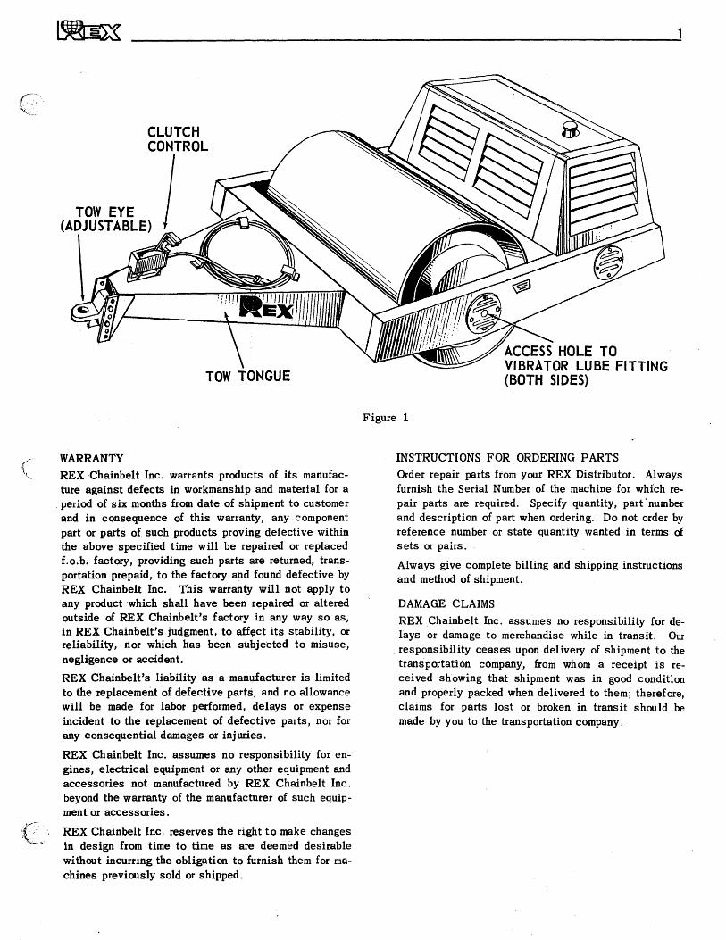
TOW EYE (ADJUSTABLE)
TOW TONGUE ACCESS HOLE TO VIBRATOR LUBE FITTING (BOTH SIDES)
CLUTCH CONTROL
tt.tt VIEW
Figure 1
WARRANTY REX Chainbelt Inc. warrants products of its manufac-ture against defects in workmanship and material for a period of six months from date of shipment to customer and in consequence of this warranty, any component part or parts of such products proving defective within the above specified time will be repaired or replaced f.o.b. factory, providing such parts are returned, trans-portation prepaid, to the factory and found defective by REX Chainbelt Inc. This warranty will not apply to any product which shall have been repaired or altered outside of REX Chainbelt's factory in any way so as, in REX Chainbelt's judgment, to affect its stability, or reliability, nor which has been subjected to misuse, negligence or accident. REX Chainbelt's liability as a manufacturer is limited to the replacement of defective parts, and no allowance will be made for labor performed, delays or expense incident to the replacement of defective parts, nor for any consequential damages or injuries.
REX Chainbelt Inc. assumes no responsibility for en-gines, electrical equipment or any other equipment and accessories not manufactured by REX Chainbelt Inc. beyond the warranty of the manufacturer of such equip-ment or accessories.
REX Chainbelt Inc. reserves the right to make changes in design from time to time as are deemed desirable without incurring the obligation to furnish them for ma-chines previously sold or shipped.
INSTRUCTIONS FOR ORDERING PARTS Order repair parts from your REX Distributor. Always furnish the Serial Number of the machine for which re-pair parts are required. Specify quantity, part . number and description of part when ordering. Do not order by reference number or state quantity wanted in terms of sets or pairs.
Always give complete billing and shipping instructions and method of shipment.
DAMAGE CLAIMS REX Chainbelt Inc. assumes no responsibility for de-lays or damage to merchandise while in transit. Our responsibility ceases upon delivery of shipment to the transportation company, from whom a receipt is re-ceived showing that shipment was in good condition and properly packed when delivered to them; therefore, claims for parts lost or broken in transit should be made by you to the transportation company.
p".
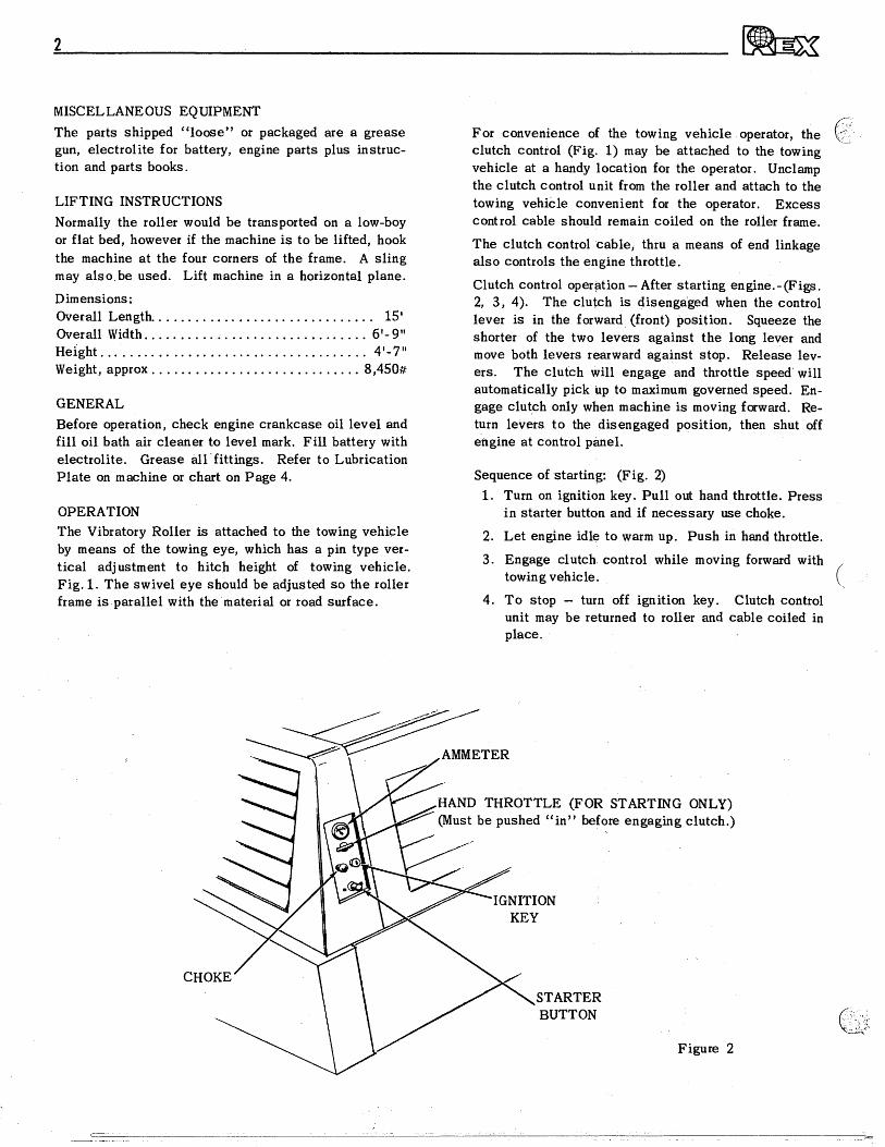
AMMETER
HAND THROTTLE (FOR STARTING ONLY) (Must be pushed "in" before engaging clutch.)
IGNITION KEY
CHOKE STARTER BUTTON
Figure 2
MISCELLANEOUS EQUIPMENT The parts shipped "loose" or packaged are a grease gun, electrolite for battery, engine parts plus instruc-tion and parts books.
LIFTING INSTRUCTIONS Normally the roller would be transported on a low-boy or flat bed, however if the machine is to be lifted, hook the machine at the four corners of the frame. A sling may also be used. Lift machine in a horizontal plane.
Dimensions: Overall Length 15' Overall Width 6'- 9" Height 4'-7" Weight, approx 8,450#
GENERAL Before operation, check engine crankcase oil level and fill oil bath air cleaner to level mark. Fill battery with electrolite. Grease all fittings. Refer to Lubrication Plate on machine or chart on Page 4.
OPERATION The Vibratory Roller is attached to the towing vehicle by means of the towing eye, which has a pin type ver-tical adjustment to hitch height of towing vehicle. Fig. 1. The swivel eye should be adjusted so the roller frame is parallel with the material or road surface.
For convenience of the towing vehicle operator, the clutch control (Fig. 1) may be attached to the towing vehicle at a handy location for the operator. Unclamp the clutch control unit from the roller and attach to the towing vehicle convenient for the operator. Excess control cable should remain coiled on the roller frame.
The clutch control cable, thru a means of end linkage also controls the engine throttle.
Clutch control operation — After starting engine.- (Figs. 2, 3, 4). The clutch is disengaged when the control lever is in the forward (front) position. Squeeze the shorter of the two levers against the long lever and move both levers rearward against stop. Release lev-ers. The clutch will engage and throttle speed will automatically pick up to maximum governed speed. En-gage clutch only when machine is moving forward. Re-turn levers to the disengaged position, then shut off engine at control panel.
Sequence of starting: (Fig. 2) 1. Turn on ignition key. Pull out hand throttle. Press
in starter button and if necessary use choke.
2. Let engine idle to warm up. Push in hand throttle.
3. Engage clutch control while moving forward with towing vehicle.
4. To stop — turn off ignition key. Clutch control unit may be returned to roller and cable coiled in place.
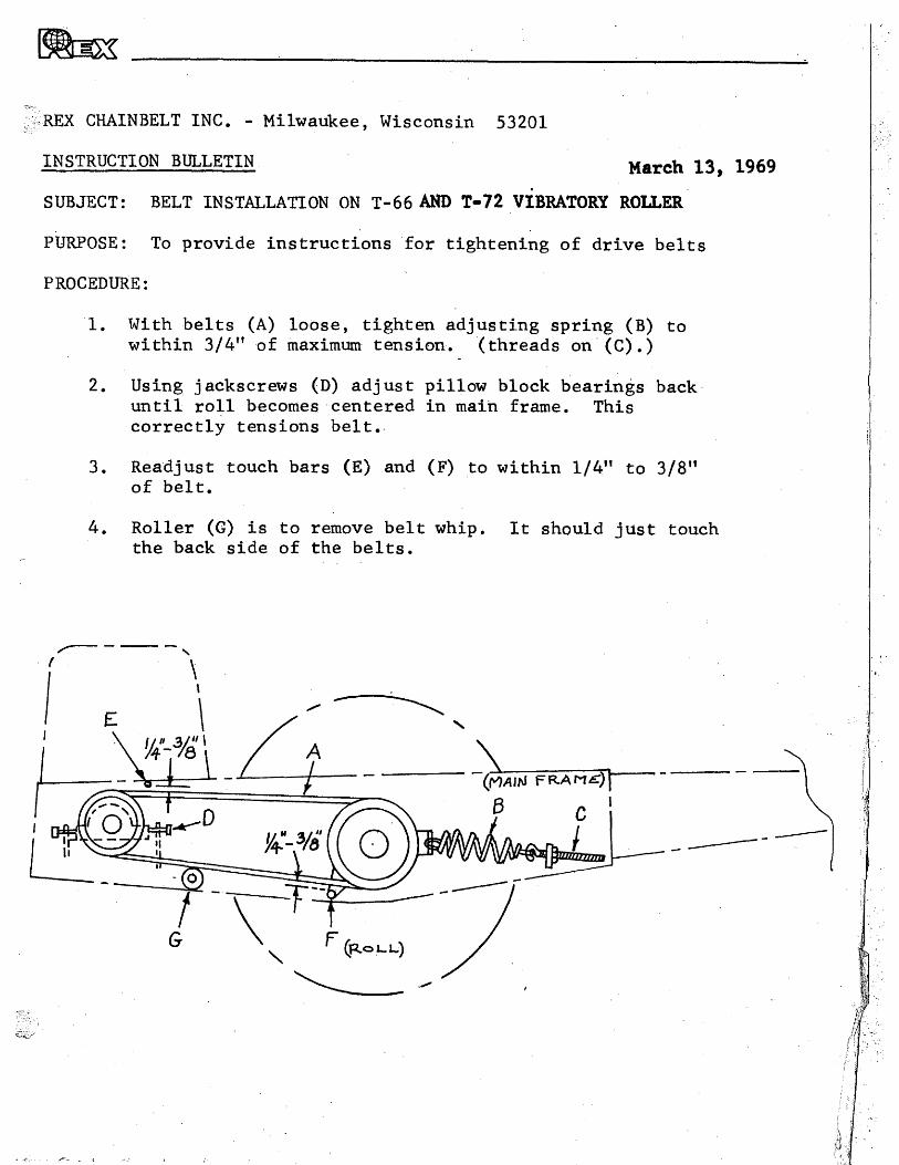
REX CHAINBELT INC. - Milwaukee, Wisconsin 53201
INSTRUCTION BULLETIN March 13, 1969
SUBJECT: BELT INSTALLATION ON T-66 AND T-72 VIBRATORY ROLLER
PURPOSE: To provide instructions for tightening of drive belts
PROCEDURE:
1. With belts (A) loose, tighten adjusting spring (B) to within 3/4" of maximum tension. (threads on (C).)
2. Using jackscrews (D) adjust pillow block bearings back until roll becomes centered in main frame. This correctly tensions belt. .
3. Readjust touch bars (E) and (F) to within 1/4" to 3/8" of belt.
4. Roller (G) is to remove belt whip. It should just touch the back side of the belts.

3
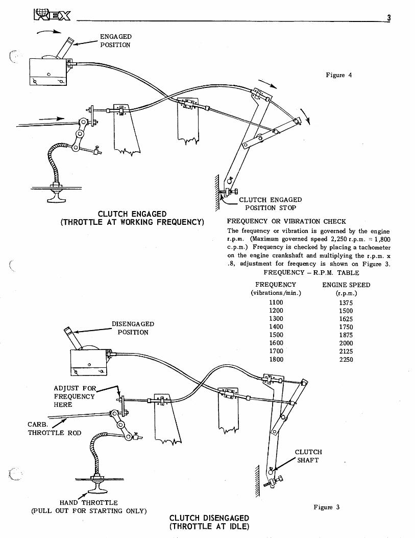
ENGAGED POSITION
Figure 4
CLUTCH ENGAGED POSITION STOP
CLUTCH ENGAGED (THROTTLE AT WORKING FREQUENCY)
DISENGAGED POSITION
ADJUST FOR/\ FREQUENCY HERE
CARB. THROTTLE ROD
FREQUENCY OR VIBRATION CHECK The frequency or vibration is governed by the engine r.p.m. (Maximum governed speed 2,250 r.p.m. = 1,800 c.p.m.) Frequency is checked by placing a tachometer on the engine crankshaft and multiplying the r.p.m. x .8, adjustment for frequency is shown on Figure 3.
FREQUENCY — R.P.M. TABLE
FREQUENCY (vibrations /min.)
ENGINE SPEED (r.p.m.)
1100 1375 1200 1500 1300 1625 1400 1750 1500 1875 1600 2000 1700 2125 1800 2250
CLUTCH SHAFT
HAND THROTTLE (PULL OUT FOR STARTING ONLY)
CLUTCH DISENGAGED (THROTTLE AT IDLE)
Figure 3
.4
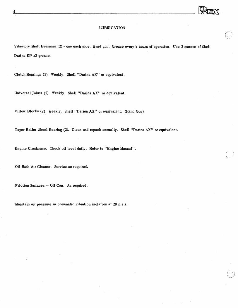
LUBRICATION
Vibratory Shaft Bearings (2) - one each side. Hand gun. Grease every 8 hours of operation. Use 2 ounces of Shell
Darina EP #2 grease.
Clutch Bearings (3). Weekly. Shell "Darina AX" or equivalent.
Universal Joints (2). Weekly. Shell "Darina AX" or equivalent.
Pillow Blocks (2). Weekly. Shell "Darina AX" or equivalent. (Hand Gun)
Taper Roller Wheel Bearing (2). Clean and repack annually. Shell "Darina AX" or equivalent.
Engine Crankcase. Check oil level daily. Refer to "Engine Manual".
Oil Bath Air Cleaner. Service as required.
Friction Surfaces — Oil Can. As required.
Maintain air pressure in pneumatic vibration isolators at 28 p.s.i.
12
aur t
p ey i
zeq
urnm
!ep o
s OA
TO &
com
fy
69 CLUTCH ASS'Y. MATERIAL
CLUTCH- THROTTLE LINKAGE — DEUTZ DIESEL
83 83 58
60
'Fb El.
0
Ot
1.1
Q.
OCI1 5',
0
O a. cD
(t)
68
13
77
BELT GUIDE ROLL ASS'Y. --- .,Ases-4..-(( -- , , EXCITER DRIVE SIDE - r„,
_____ .c.„..„, ....ts ..., .... _......... ,,,,L...„ iiiir411 II .....-10L_ 0.--...„3,.., •
72 63
24 36
7 82 3
81
,411\ t • 71 DEUTZ DISEL OPTION ,--
272527 2
4 I 16 11
5 14/ II 74
I 1 I I
7 WISCONSIN GAS OPTIO
78
80
46 56 57 05
42
CLUTCH - THROTTLE LINKAGE
,l id
_ 1 AGE
19 49
55 53
54
21
WISCONSIN GAS
'Y'S
f1
NI
03
1N
IN
cI • )C
C)
S
i 0
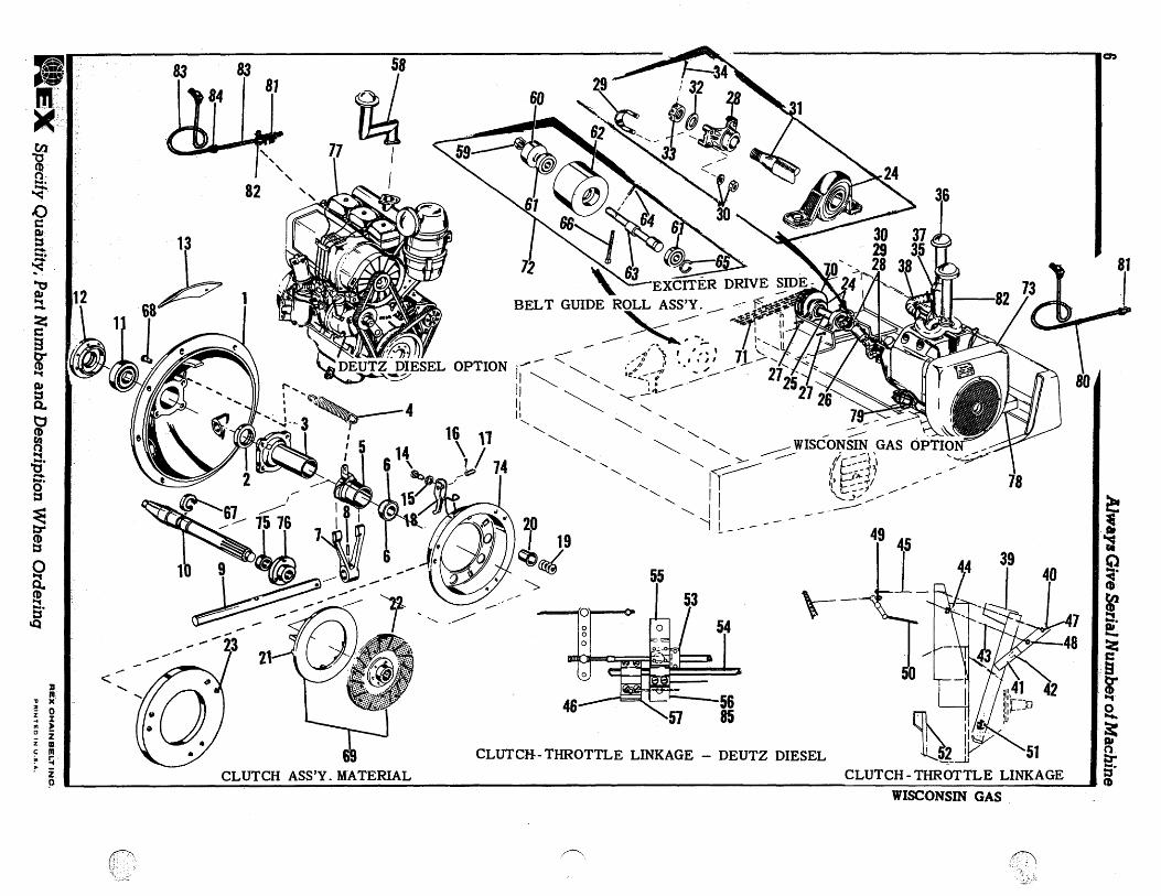
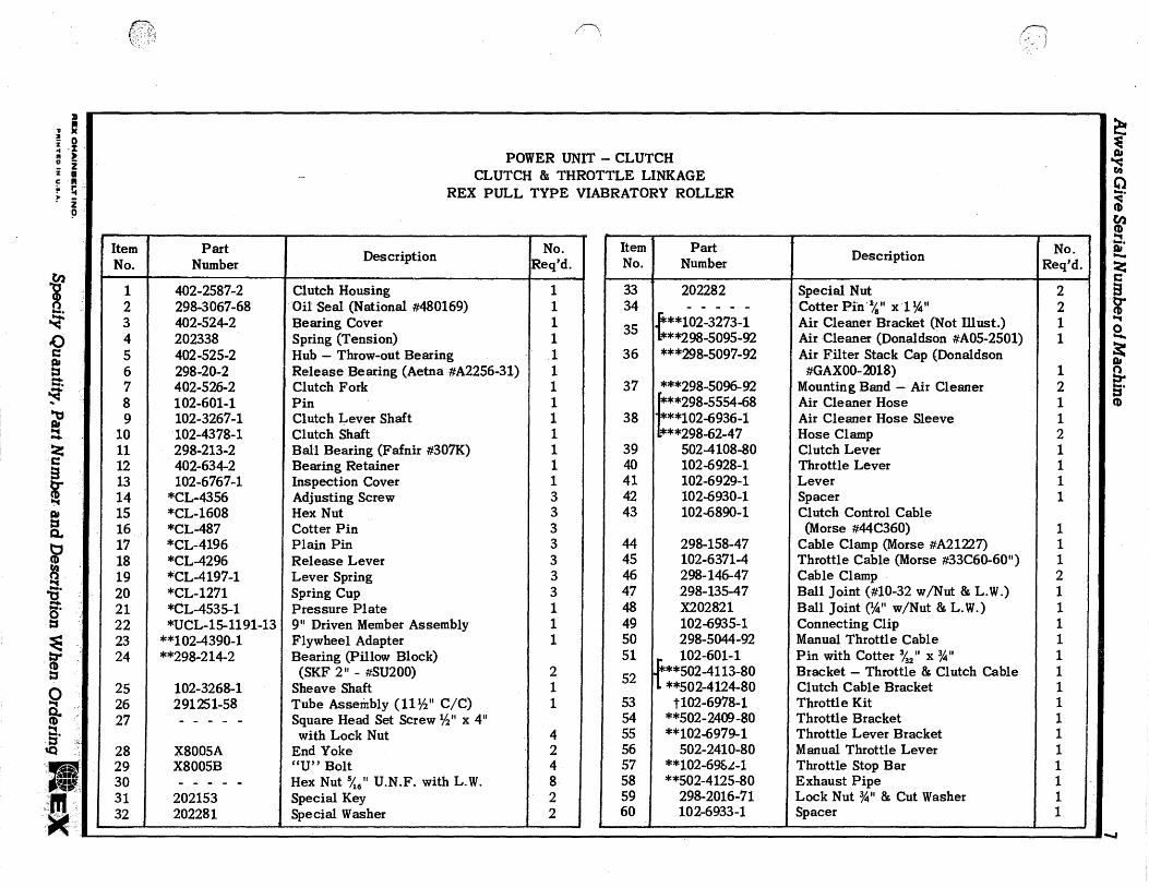
POWER UNIT — CLUTCH CLUTCH & THROTTLE LINKAGE
REX PULL TYPE VIABRATORY ROLLER
a upp
epti .r
equm
N M
in °A
ID s A
emiy
• MID* 1•1111► :•
•
No. I Part
Number D Description Reqtem
_ No.
'd.
1 402-2587-2 Clutch Housing 1 2 298-3067-68 Oil Seal (National #480169) 1 3 402-524-2 Bearing Cover 1 4 202338 Spring (Tension) 1 5 402-525-2 Hub — Throw-out Bearing . 1 6 298-20-2 Release Bearing (Aetna #A2256-31) 1 7 402-526-2 Clutch Fork 1 8 102-601-1 Pin 1 9 102-3267-1 Clutch Lever Shaft 1
10 102-4378-1 Clutch Shaft 1 11 298-213-2 Ball Bearing (Fafnir #307K) 1 12 402-634-2 Bearing Retainer 1 13 102-6767-1 Inspection Cover 1 14 *CL-4356 Adjusting Screw 3 15 *CL-1608 Hex Nut 3 16 *CL-487 Cotter Pin 3 17 *CL-4196 Plain Pin 3 18 *CL-4296 Release Lever 3 19 *CL-4197-1 Lever Spring 3 20 *CL-1271 Spring Cup 3 21 *CL-4535-1 Pressure Plate 1 22 *UCL-15-1191-13 9" Driven Member Assembly 1 23 **102-4390-1 Flywheel Adapter 1 24 "298-214-2 Bearing (Pillow Block)
(SKF 2" - #SU200) 2 25 102-3268-1 Sheave Shaft 1 26 291251-58 Tube Assembly (11 1/2" C/C) 1 27 Square Head Set Screw Y2 " x 4"
with Lock Nut 4 28 X8005A End Yoke 2 29 X8005B "U" Bolt 4 30 Hex Nut 546 " U.N.F. with L.W. 8 31 202153 Special Key 2 32 202281 Special Washer 2
' . Item No.
Part Number Description No.
Req'd.
33 202282 Special Nut 2 34 Cotter Pin 1/8 " x 1 /4" 2 35 **102-3273-1
t**298-5095-92 Air Cleaner Bracket (Not Must.) Air Cleaner (Donaldson #A05-2501)
1 1
36 ***298-5097-92 Air Filter Stack Cap (Donaldson #GAX00-2018) 1
37 ***298-5096-92 Mounting Band — Air Cleaner 2 ***298-5554-68 Air Cleaner Hose 1
38 ***102-6936-1 I
Air Cleaner Hose Sleeve 1 ***298-62-47 Hose Clamp 2
39 502-4108-80 Clutch Lever 1 40 102-6928-1 Throttle Lever 1 41 102-6929-1 Lever 1 42 102-6930-1 Spacer 1 43 102-6890-1 Clutch Control Cable
(Morse #44C360) 1 44 298-158-47 Cable Clamp (Morse #A21227) 1 45 102-6371-4 Throttle Cable (Morse #33C60-60") 1 46 298-146-47 Cable Clamp 2 47 298-135-47 Ball Joint (#10-32 w/Nut & L.W.) 1 48 X202821 Ball Joint (A" w/Nut & L.W.) 1 49 102-6935-1 Connecting Clip 1 50 298-5044-92 Manual Throttle Cable 1 51 102-601-1 Pin with Cotter %2 " x 3/4" 1 52 t**502-4113-80
L *4'502-4124-80 Bracket — Throttle & Clutch Cable Clutch Cable Bracket
1 1
53 t102-6978-1 Throttle Kit 1 54 "502-2409-80 Throttle Bracket 1 55 "102-6979-1 Throttle Lever Bracket 1 56 502-2410-80 Manual Throttle Lever 1 57 "102-6962-1 Throttle Stop Bar 1 58 "502-4125-80 Exhaust Pipe 1 59 298-2016-71 Lock Nut 3/4" & Cut Washer 1 60 102-6933-1 Spacer 1
1
t/2 CD r4;
1" 0 a, z
tr (D
a, z
co
O
cD
t.i.. *ti
0
cr.
•V
•S•11
NI 0
31
NI
tic
l m 0
2 in
2 0
Part Number
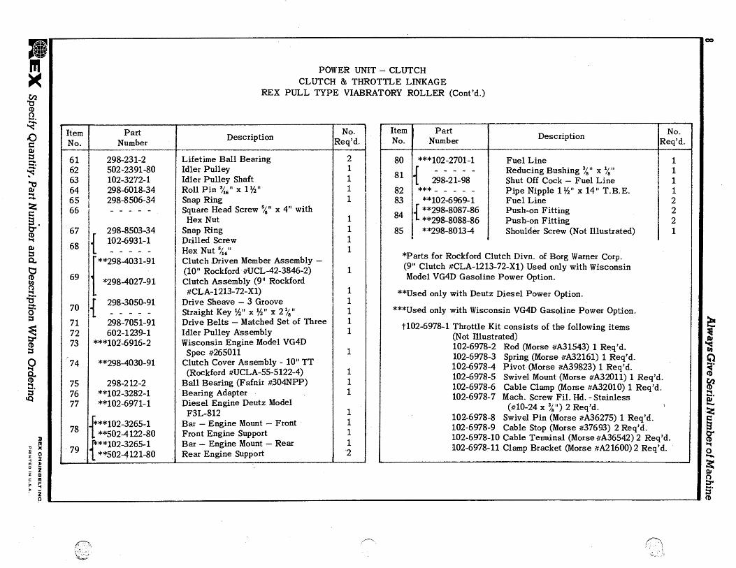
***102-2701-1
{ 298-21-98 *** "102-6969-1
84 "298-8087-86 "298-8088-86
85 "298-8013-4
Description No. Req'd.
Fuel Line 1 Reducing Bushing %" x 1 Shut Off Cock — Fuel Line 1 Pipe Nipple 1 1/2" x 14" T.B.E. 1 Fuel Line 2 Push-on Fitting 2 Push-on Fitting 2 Shoulder Screw (Not Illustrated) 1
80
81
82 83
Item No.
*Parts for Rockford Clutch Divn. of Borg Warner Corp. (9" Clutch #CLA-1213-72-X1) Used only with Wisconsin Model VG4D Gasoline Power Option.
**Used only with Deutz Diesel Power Option.
***Used only with Wisconsin VG4D Gasoline Power Option.
t102-6978-1 Throttle Kit consists of the following items (Not Illustrated) 102-6978-2 Rod (Morse #A31543) 1 Req'd. 102-6978-3 Spring (Morse #A32161) 1 Req'd. 102-6978-4 Pivot (Morse #A39823) 1 Req'd. 102-6978-5 Swivel Mount (Morse #A32011) 1 Req'd. 102-6978-6 Cable Clamp (Morse #A32010) 1 Req'd. 102-6978-7 Mach. Screw Fil. Hd. - Stainless
(#10-24 x 34") 2 Req'd. 102-6978-8 Swivel Pin (Morse #A36275) 1 Req'd. 102-6978-9 Cable Stop (Morse #37693) 2 Req'd. 102-6978-10 Cable Terminal (Morse #A36542) 2 Req'd. 102-6978-11 Clamp Bracket (Morse #A21600)2 Req'd.
POWER UNIT — CLUTCH CLUTCH & THROTTLE LINKAGE
REX PULL TYPE VIABRATORY ROLLER (Cont'd.)
Item No.
Part Number
Description No. Req'd.
61 298-231-2 Lifetime Ball Bearing 2 62 502-2391-80 Idler Pulley 1 63 102-3272-1 Idler Pulley Shaft 1 64 298-6018-34 Roll Pin 346 " x 1 1/2 " 1 65 298-8506-34 Snap Ring 1 66 Square Head Screw 5/8 " x 4" with
Hex Nut 1 67 298-8503-34 Snap Ring 1
{ 102-6931-1 Drilled Screw 1 68 Hex Nut 546 " 1
**298-4031-91 Clutch Driven Member Assembly —
69 *298-4027-91 (10" Rockford #UCL-42-3846-2) Clutch Assembly (9" Rockford
1
#CLA-1213-72-X1) 1
70 1 298-3050-91 Drive Sheave — 3 Groove Straight Key 1/2" x 1/2" x 2 1/$ "
1 1
71 298-7051-91 Drive Belts — Matched Set of Three 1 72 602-1239-1 Idler Pulley Assembly 1 73 ***102-6916-2 Wisconsin Engine Model VG4D
Spec #265011 1 74 **298-4030-91 Clutch Cover Assembly - 10" TT
(Rockford #UCLA-55-5122-4) 1 75 298-212-2 Ball Bearing (Fafnir #304NPP) 1 76 "102-3282-1 Bearing Adapter 1 77 **102-6971-1 Diesel Engine Deutz Model
F3L-812 1
78 i;"102-3265-1 "502-4122-80
Bar — Engine Mount — Front Front Engine Support
1 1
79 "102-3265-1 dr "502-4121-80
Bar — Engine Mount — Rear Rear Engine Support
1 2
aurp
eN z
ecu
unN
t ep a
s °A
m si ie
mni
Always Give Serial Number of Machine
111 =meowNV Specify Quantity, Part Number and Description When Ordering REX CHAINBELT INC.
PRINTED IN U.S.A.
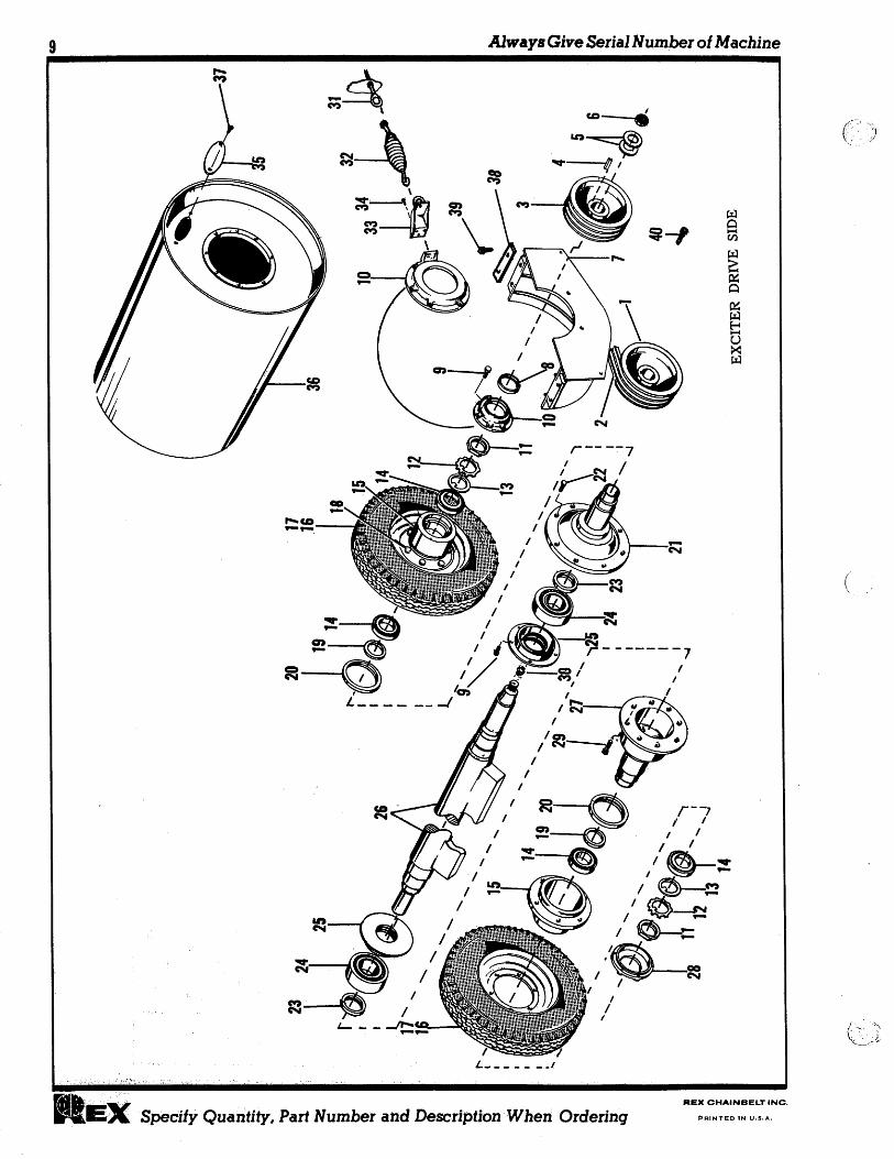
DRIVE ROLL ASSEMBLY REX PULL TYPE VIABRATORY ROLLER
Item No.
Part Number Description
, No.
Req'd.
1 298-3050-91 Drive Sheave (3 Groove)
r.4 r-4 r
-4 N
r-IV
NA
v-
IN
NN
V*V
-N
NN
NC:24
NN
2 298-7051-91 Matched Set of 3 Drive Belts 3 402-1642-2 Pulley — Deep Groove 4 Str. Key %" x 5/8 " x 2 3/4" 5 Cut Washer 11/2" 6 298-19-71 Self-Locking Nut (1 1/2" - 12) 7 502-4107-80 Tire Housing Half 8 298-3063-68 Oil Seal — 3 1/2" I.D. 9 298-28-93 Self-Locking Cap Screw 3/8 " x 1"
10 402-1643-2 Seal Carrier (Drive Side) 11 298-18-71 Lock Nut — Bearing 12 298-12-97 Lock Washer — Bearing 13 298-13-97 Washer — Keyed Bearing
14 1298-207-2 298-208-2
Bearing Cup Bearing Cone
15 402-2584-2 Wheel Hub
16 {298-6035-68 298-606-68
Tire — Radial Ply Tube — 5:00 x 15
17 502-4106-80 Wheel 18 298-30-93 Self-Locking Cap Screw 5/8 " x 1 %" 19 102-6926-1 Bearing Spacer 20 298-3064-68 Oil Seal — 614" I.D. ,
Item No.
Part Number Description No.
Req'd. 21 t 402-2585-2 Hub — Roll — (Drive Side) 1 22 . 298-31-93 Self-Locking Cap Screw 3/4" x 2 1/2"
(Drive Side) 8 23 298-3062-68 Oil Seal — 31/2" I.D. 2 24 298-206-2 Spherical Bearing 2 25 402-1641-2 Labyrinth Bearing Retainer 2 26 502-5786-80 Exciter Shaft 1 27 402-2586-2 Hub — Roll (Opposite Drive Side) 1 28 402-1644-2 Seal Carrier (Opposite Drive Side) 1 29 298-32-93 Self-Locking Cap Screw 3/4" x 3"
(Driven Side) 8 30 1627B Grease Fitting — 1/4 N.P.T. 2 31 502-2390-80 Screw — Spring Take-Up 1 32 102-4376-1 Spring 1 33 502-4109-80 Bracket 1 34 Cap Screw 3/8 " x 1" with L.W. 3 35 102-3264-1 Inspection Cover 1 36 502-5785-80 Roll 4 1
37 38 102-6927-1 w with L.W.
" x 1W"a sChaepr Screw Lock 2 4
39 3/4 " x 2 1/s" Cap Screw with Lock Nut 8
8 1/2 2" x 3/4" Cap Screw (Self-Locking) 8 40 _3" x 3/4" Cap Screw (Self-Locking) 1
z m 0
z C
x 0
m rt
0
Alw
ays Give Serial N
umber of M
achine
Always Give Serial Number of Machine
REX CHAINBELT INC.
nl=.4111, Specify Quantity, Part Number and Description When Ordering PRINTED IN U.S.A.
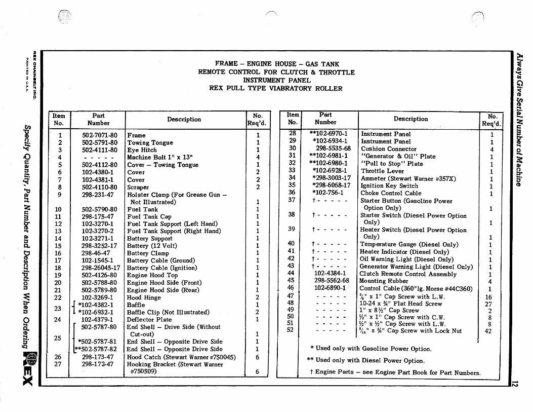
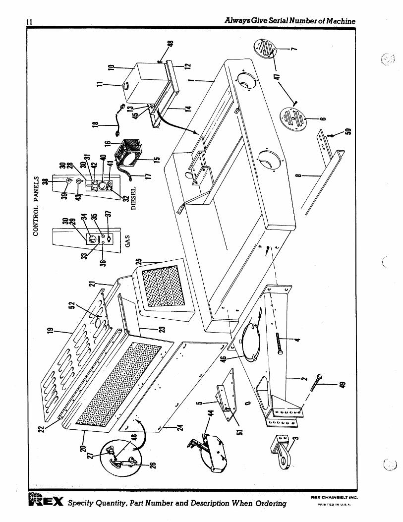
FRAME — ENGINE HOUSE — GAS TANK REMOTE CONTROL FOR CLUTCH & THROTTLE
INSTRUMENT PANEL REX PULL TYPE VIABRATORY ROLLER
Item No.
Part Number Description No.
Req'd.
1 502-7071-80 Frame 1 2 502-5791-80 Towing Tongue 1 3 502-4111-80 Eye Hitch 1 4 Machine Bolt 1" x 13" 4 5 502-4112-80 Cover — Towing Tongue 1 6 102-4380-1 Cover 2 7 102-4381-1 Cover 2 8 502-4110-80 Scraper 2 9 298-231-47 Holster Clamp (For Grease Gun —
Not Illustrated) 1 10 502-5790-80 Fuel Tank 1 11 298-175-47 Fuel Tank Cap 1 12 102-3270-1 Fuel Tank Support (Left Hand) 1 13 102-3270-2 Fuel Tank Support (Right Hand) 1 14 102-3271-1 Battery Support 1 15 298-3252-17 Battery (12 Volt) 1 16 298-46-47 Battery Clamp 1 17 102-1545-1 Battery Cable (Ground) 1 18 298-26045-17 Battery Cable (Ignition) 1 19 502-4126-80 Engine Hood Top 1 20 502-5788-80 Engine Hood Side (Front) 1 21 502-5789-80 Engine Hood Side (Rear) 1 22 102-3269-1 Hood Hinge 2
23 i *10243824 *102-6932-1
Baffle Baffle Clip (Not Illustrated)
1 2
24 102-4379-1 Deflector Plate 1 502-5787-80 End Shell — Drive Side (Without
25 *502-5787-81 Cut-out)
End Shell — Opposite Drive Side 1 1
**502-5787-82 End Shell — Opposite Drive Side 1 26 298-173-47 Hood Catch (Stewart Warner #750045) 6 27
[ 298-172-47 Hooking Bracket (Stewart Warner
#750509) 6
Item No.
Part Number Description
•
No. Req'd.
28 "102-6970-1 Instrument Panel 1 29 *102-6934-1 Instrument Panel 1 30 298-5535-68 Cushion Connector 4 31 **102-6981-1 "Generator & Oil" Plate 1 32 **102-6980-1 "Pull to Stop" Plate 1 33 *102-6928-1 Throttle Lever 1 34 *298-3003-17 Ammeter (Stewart Warner #357X) 1 35 *298-6068-17 Ignition Key Switch 1 36 *102-756-1 Choke Control Cable 1 37 t Starter Button (Gasoline Power
Option Only) 1 38 t Starter Switch (Diesel Power Option
Only) 1 39 t Heater Switch (Diesel Power Option
Only) 1 40 t Temperature Gauge (Diesel Only) 1 41 t Heater Indicator (Diesel Only) 1 42 t Oil Warning Light (Diesel Only) 1 43 t Generator Warning Light (Diesel Only) 1 44 102-4384-1 Clutch Remote Control Assembly 1 45 298-5562-68 Mounting Rubber 4 46 102-6890-1 Control Cable (360" lg. Morse #44C360) 1 47 3/8 " x 1" Cap Screw with L.W. 16 48 10-24 x 3/4" Flat Head Screw 27 49 1" x 81/2" Cap Screw 2 50 1/2" x 1" Cap Screw with C.W. 8 51 1/2" x 1/2" Cap Screw with L.W. 8 52
15/6 " x 3/4" Cap Screw with Lock Nut
i 42
* Used only with Gasoline Power Option.
** Used only with Diesel Power Option.
t Engine Parts — see Engine Part Book for Part Numbers.
pecify Q
uantity, Part Num
ber and Description W
hen O
rdering
'11
.1•11
NI
03
1N
I
M
0
I
Always Give Serial Num
ber of Machine

Maciii39n, Ind:;-
Warren, Pcnri West I!Iil.tt'a uk Worceci ter, ,lylass. Toronto, Canada
PLANTS: gitif a
Dot


![THE ROOT ROT OF TARO - University of Hawaii · walter f. frear hawaii agricultural experiment station, honolull], g, smith, special agent in charge. bu lletin no.2. the root rot of](https://img.pdfslide.net/doc/110x75/5bebcc4d09d3f2ff498cd22d/the-root-rot-of-taro-university-of-hawaii-walter-f-frear-hawaii-agricultural.jpg)