Embed Size (px)
Citation preview
lli~~I UNIVERSITI TEKNIKAL MALAYSIA MELAKA
UNIVERSITI TEKNIKAL MALAYSIA MELAKA
DESIGN AND ANALYSIS OF FINS UNDER UNCERTAINTY HEAT
CAPACITY
This repott submitted in accordance with requirement of the Universiti Teknikal
Malaysia Melaka (UTeM) for the Bachelor Degree of Manufacturing Engineering
(Manufacturing Design) (Hons.)
by
CHONG SEE YING
B051010010
890316-59-5344
FACULTY OF MANUFACTURING ENGINEERING
2014
© Universiti Teknikal Malaysia Melaka

UNIVERSITI TEKNIKAL MALAYSIA MELAKA
BORANG PENGESAHAN STATUS LAPORAN PROJEK SARJANA MUDA
TAJUK: DESIGN AND ANALYSIS OF FINS UNDER UNCERTAINTY HEAT CAPACITY
SESI PENGAJIAN: 2013/14 Semester 2
Saya CHONG SEE YING
mengaku membenarkan Laporan PSM ini disimpan di Perpustakaan Universiti Teknikal Malaysia Melaka (UTeM) dengan syarat-syarat kegunaan seperti berikut:
1. Laporan PSM adalah hak milik Universiti Teknikal Malaysia Melaka dan penulis. 2. Perpustakaan Universiti Teknikal Malaysia Melaka dibenarkan membuat salinan
untuk tujuan pengajian sahaja dengan izin penulis. 3. Perpustakaan dibenarkan membuat salinan laporan PSM ini sebagai bahan
pertukaran antara institusi pengajian tinggi. 4. **Sila tandakan ( ./)
D SULIT
TERHAD
TIDAK TERHAD
Alamat Tetap:
NO. 4, TAMAN NAGAMAS,
71650 TITI,
(Mengandungi maklumat yang berdarjah keselamatan atau kepentingan Malaysia sebagaimana yang termaktub dalam AKTA RAHSIA RASMI 1972)
(Mengandungi maklumat TERHAD yang telah ditentukan oleh organisasi/badan di mana penyelidikan dijalankan)
Cop Rasmi:
Disahkan oleh:
~~-
DR. TAUFIK Senior Lecturer
JELEBU, NEGERI SEMBILAN
Faculty of Manufacturing Engineerfn1 . Unlverslti Teknikal Malaysia Melaall
Hang Tuah Jaya 76100 Durian Tunggal, Melab
Tarikh: 23 MAY 2014
** Jika Laporan PSM ini SULIT atau TERHAD, sila lampirkan surat daripada pihak berkuasa/organisasi berkenaan dengan menyatakan sekali sebab dan tempoh laporan PSM ini perlu dikelaskan sebagai SULIT atau TERHAD.
C Universiti Teknikal Malaysia Melaka

DECLARATION
I hereby, declared this report entitled "Design and Analysis of Fins under
Uncertainty Heat Capacity" is the results of my own research except as cited in
references.
Signature
Author's Name
Date
CHONG SEE YING
261h JUNE 2014
© Universiti Teknikal Malaysia Melaka
APPROVAL
This report is submitted to the Faculty of Manufacturing Engineering of UTeM
as a partial fulfillment of the requirements for the degree of Bachelor of
Manufacturing Engineering (Manufacturing Design) (Hons.). The member of
the supervisory committee is as follow:
~/ · ·············~-~---······ DR. TAUFIK
~nior Lectunr Faculty of Manufacturing Engineerinf Unlvenlti Teknikal Malaysia Mel.ta
Hang Tuah Jaya 76100 Durian Tunggal, Melab
© Universiti Teknikal Malaysia Melaka
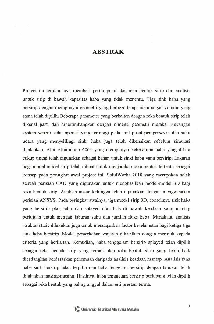
ABSTRAK
Project ini terutamanya memberi pertumpuan atas reka bentuk sirip dan analisis
untuk sirip di bawah kapasitas haba yang tidak menentu. Tiga sink haba yang
bersirip dengan mempunyai geometri yang berbeza tetapi mempunyai volume yang
sama telah dipilih. Beberapa parameter yang berkaitan dengan reka bentuk sirip telah
dikenal pasti dan dipertimbangkan dengan dimensi geometri meraka. Kekangan
system seperti suhu operasi yang tertinggi pada unit pusat pemprosesan dan suhu
udara yang menyelilingi sinki haba juga telah dikenalkan sebelum simulasi
dijalankan. Aloi Aluminium 6063 yang mempunyai keberaliran haba yang dikira
cukup tinggi telah digunakan sebagai bahan untuk sinki haba yang bersirip. Lakaran
bagi model-model sirip telah dibuat untuk menjadikan reka bentuk tertentu sebagai
konsep pada peringkat awal project ini. SolidWorks 2010 yang merupakan salah
sebuah perisian CAD yang digunakan untuk menghasilkan model-model 3D bagi
reka bentuk sirip. Analisis unsur terhingga telah dijalankan dengan menggunakan
perisian ANSYS. Pada peringkat awalnya, tiga model sirip 3D, contohnya sink haba
yang bersirip plat, jalur dan splayed dianalisis di bawah keadaan yang mantap
bertujuan untuk mengaji taburan suhu dan jumlah fluks haba. Manakala, analisis
struktur static dilakukan juga untuk mendapatkan factor keselamatan bagi ketiga-tiga
sink haba bersirip. Model pemarkahan wajaran dihasilkan dengan merujuk kepada
criteria yang berkaitan. Kemudian, haba tenggelam bersirip splayed telah dipilih
sebagai reka bentuk sirip yang terbaik dan reka bentuk sirip yang lebih baik
dicadangkan berdasarkan penemuan daripada analisis keadaan mantap. Analisis fana
haba sink bersirip telah terpilih dan haba tengelam bersirip dengan tebukan telah
dijalankan masing-masing. Hasilnya, haba tenggelam bersirip berlubang telah dipilih
sebagai reka bentuk yang paling unggul dalam erti prestasi terma.
© Universiti Teknikal Malaysia Melaka
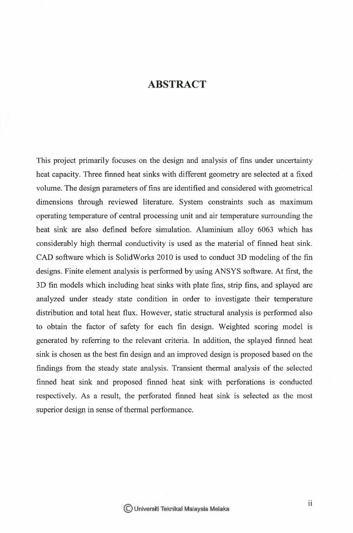
ABSTRACT
This project primarily focuses on the design and analysis of fins under uncertainty
heat capacity. Three finned heat sinks with different geometry are selected at a fixed
volume. The design parameters of fins are identified and considered with geometrical
dimensions through reviewed literature. System constraints such as maximum
operating temperature of central processing unit and air temperature surrounding the
heat sink are also defined before simulation. Aluminium alloy 6063 which has
considerably high thermal conductivity is used as the material of finned heat sink.
CAD software which is SolidWorks 2010 is used to conduct 3D modeling of the fin
designs. Finite element analysis is performed by using ANSYS software. At first, the
3D fin models which including heat sinks with plate fins, strip fins, and splayed are
analyzed under steady state condition in order to investigate their temperature
distribution and total heat flux. However, static structural analysis is performed also
to obtain the factor of safety for each fin design. Weighted scoring model is
generated by referring to the relevant criteria. In addition, the splayed finned heat
sink is chosen as the best fin design and an improved design is proposed based on the
findings from the steady state analysis. Transient thermal analysis of the selected
finned heat sink and proposed finned heat sink with perforations is conducted
respectively. As a result, the perforated finned heat sink is selected as the most
superior design in sense of thermal performance.
© Universiti Teknikal Malaysia Melaka 11

DEDICATION
To my beloved parents, siblings and friends due to their love and support.
© Universiti Teknikal Malaysia Melaka Ill

ACKNOWLEDGEMENT
I would like to express my deep gratitude to Dr. Taufik, my supervisor for his patient
guidance, useful advice, and assistance along the progress of this project. I am
grateful for his professionalism and his tolerance to guide me.
My grateful thanks are also extended to my parents and all my family members for
their love, support and concerns.
Besides, I would also like to thank to my fellow friends who kindly provide
assistance and support to me without hesitations.
© Universiti Teknikal Malaysia Melaka lV
TABLE OF CONTENTS
Abstrak
Abstract
Dedication
Acknowledgement
Table of Contents
List of Tables
List of Figures
List of Abbreviations, Symbols and Nomenclature
CHAPTER 1: INTRODUCTION
1.1 Background
1.2 Problem Statement
1.3 Objectives
1.4 Scope of Project
1.5 Project Organization
CHAPTER 2: LITERATURE REVIEW
2.1 Overview of Finned Heat Sink
2.1.1 Introduction
2.1.2 Categories of Heat Sinks
2.1.3 Types of Heat Sinks
2.1.4 Fin Designs
2.1.5 Overview of Fin Designs
2.2 Fin Design Principles
2.2.1 Introduction
2.2.2 System Constraints
2.2.2.1 Ambient Temperature
2.2.2.2 Maximum Operating Temperature
2.2.2.3 Heat Removal Capability
© Universiti Teknikal Malaysia Melaka
11
111
lV
v
lX
x
Xll
1
1
3
4
4
5
7
7
7
8
11
13
16
17
17
17
18
18
18
v
2.3
2.4
2.5
2.6
2.2.2.4 Maximum Volume of Heat Sink
2.2.3 Design Parameters
2.2.3.1 Fin Material
2.2.3.2 Number of Fins
2.2.3.3 Fin Shapes
2.2.3.4 Fin Alignments
2.2.3.5 Base Plate Thickness and Fin Height
2.2.3.6 Fin Efficiency
2.2.3.7 Fin Effectiveness
Material of Fins
2.3.1 Introduction
2.3.2 Aluminium
2.3 .3 Aluminium Alloy
2.3.4 Aluminium Alloy 6063
Heat Transfer Mechanisms
2.4.1 Introduction
2.4.2 Conduction
2.4.3 Convection
2.4.4 Radiation
Design Tool
2.5.1 Introduction
2.5.2 SolidWorks Software
Engineering Analysis Tools
2.6.1 Introduction
2.6.2 Steps in Finite Element Analysis
2.6.2.1 Preprocessing
2.6.2.2 Solution
2.6.2.l Post-processing
2.6.3 ANSYS
2.6.3.1 Thermal Analysis
19
19
21
21
21
21
22
22
24
25
25
26
27
28
29
29
30
30
32
33
33
33
34
34
35
35
35
36
36
37
2.6.3.1 .1 Steady State Condition and Transient Condition 38
2.6.3 .1.2 Temperature Distribution 38
2.6.3.1.3 Heat Flux 38
© Universiti Teknikal Malaysia Melaka VI

2.6.4 Summary
CHAPTER3:METHODOLOGY
3.1 Overview Methodology
3.2 Phase 1
3.2.1 Introduction
3.2.2 Literature Review
3.3 Phase 2
3.3.1 Data Mining
3.3.1.1 Design Parameters of Fins
3.3.1.2 Uncertainty Heat Capacity for Fin Analysis
3.3.1.3 Material Used
3.3.2 3D Modeling
3.3.3 Formulation Analysis
3.3.3.1 Assumptions
3.3.3.2 Convection Heat Transfer Coefficient
3.4 Phase 3
3.4.1 Simulation
3.4.2 Steady State Thermal Analysis
3.4.2.1 Pre-Processing
3.4.2.2 Solution
3.4.2.3 Post-Processing
3.4.3 Static Structural
3.4.4 Selection of Fin Design
3.4.5 Proposed Design
3.4.6 Transient Thermal Analysis
3.5 Phase 4
3.5.1 Results and Discussions
3.5.2 Conclusion and Recommendation
CHAPTER 4: RES UL TS AND DISCUSSION
4.1 Steady State Thermal Analysis
4.1 .1 Temperature Distribution of Finned Heat Sinks
© Universiti Teknikal Malaysia Melaka
39
40
40
42
42
42
43
43
43
46
46
46
47
48
48
50
50
51
52
55
55
56
59
60
62
64
64
64
65
65
66
Vll

4.1.2 Total Heat Flux of Finned Heat Sink
4.2 Static Structural Analysis
4.3 Fin Efficiency and Overall Fin Effectiveness
4.4 Selection of Fin Design
4.5 Transient Thermal Analysis
4.5.1 Temperature Distribution of Selected Fin Design
4.5.2 Total Heat Flux of Selected Fin Design
4.5.3 Temperature Distribution of Proposed Fin Design
4.5.4 Total Heat Flux of Proposed Fin Design
4.5.5 Comparison between Selected Finned Heat Sink and
Proposed Finned Heat Sink
4.6 Discussions
CHAPTER 5: CONCLUSION AND RECOMMENDATIONS
5.1
5.2
Conclusion
Recommendations
REFERENCES
APPENDICES
A Gantt Chart
B Properties of Aluminium Alloy 6063
67
68
70
71
72
73
76
80
83
87
89
92
92
93
94
C Tabular Data for Properties of Air and Convection Heat Transfer Coefficient
D Temperature Distribution and Total Heat Flux in Steady State Thermal
Analysis
E Theoretical Calculations for Fin Efficiency and Overall Fin Effectiveness
F Temperature Distribution in Transient Thermal Analysis
G Total Heat Flux in Transient Thermal Analysis
H Engineering Drawings
I Results ofFEA
© Universiti Teknikal Malaysia Melaka Vlll
2.1
2.2
2.3
2.4
2.5
2.6
2.7
2.8
3.1
3.2
4.1
4.2
4.3 (a)
4.3 (b)
4.4
4.5
4.6
4.7
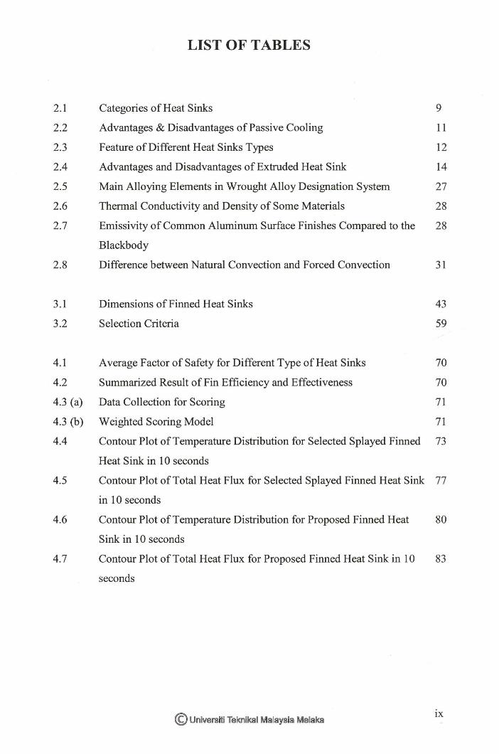
LIST OF TABLES
Categories of Heat Sinks
Advantages & Disadvantages of Passive Cooling
Feature of Different Heat Sinks Types
Advantages and Disadvantages of Extruded Heat Sink
Main Alloying Elements in Wrought Alloy Designation System
Thermal Conductivity and Density of Some Materials
Emissivity of Common Aluminum Surface Finishes Compared to the
Blackbody
Difference between Natural Convection and Forced Convection
Dimensions of Finned Heat Sinks
Selection Criteria
Average Factor of Safety for Different Type of Heat Sinks
Summarized Result of Fin Efficiency and Effectiveness
Data Collection for Scoring
Weighted Scoring Model
Contour Plot of Temperature Distribution for Selected Splayed Finned
Heat Sink in 10 seconds
Contour Plot of Total Heat Flux for Selected Splayed Finned Heat Sink
in 10 seconds
Contour Plot of Temperature Distribution for Proposed Finned Heat
Sink in 10 seconds
Contour Plot of Total Heat Flux for Proposed Finned Heat Sink in 10
seconds
© Universiti Teknikal Malaysia Melaka
9
11
12
14
27
28
28
31
43
59
70
70
71
71
73
77
80
83
IX

LIST OF FIGURES
1.1 Thermal Flow Variation and CPU die size depending on the 2
production year
2.1 The Schematic Diagram of Different Fin Designs 14
2.2 Different Fin Profiles 15
2.3 Heat Sinks with Oblique/Splayed Plate and Pin Fins 15
2.4 The Schematic Diagram of Heat Sink Design 20
2.5 The Top-View and Side-View of Splayed Pin Finned Heat Sink 20
2.6 The Ideal and Actual Temperature Distribution in a Fin 23
2.7 The Effectiveness of a Fin 24
2.8 Difference between Heat Transfer Mechanisms 29
3.1 Process Development of Entire Project 41
3.2 (a) Heat Sink with Plate Fins 44
3.2 (b) Heat Sink with Strip Fins 45
3.2 (c) Heat Sink with Splayed Fins 45
3.3 Steps of Drawing Creation Using SolidWorks 47
3.4 Heat Flow by Convection 49
3.5 Steps of Simulation Using ANSYS Software 51
3.6 (a) Procedure in Conducting Steady State Thermal Analysis 52
3.6 (b) Detail Steps in conducting Steady State Thermal Analysis 52
3.7 Meshing of Plate Finned Heat Sink 53
3.8 (a) Temperature Setting 53
3.8 (b) Temperature Applied 54
3.9 (a) Convection Heat Transfer Coefficient Setting in form of Tabular Data 54
3.9 (b) Convection Heat Transfer Applied 55
3.IO(a) Procedure in Conducting Static Structural Analysis 56
3.10 (b) Detail Steps in Conducting Static Structural Analysis 57
3.11 Contour Plot of Imported Body Temperature 57
3.12 (a) Fixed Support Applied 58
© Universiti Teknikal Malaysia Melaka x

3.12 (b) Standard Earth Gravity Applied 58
3.13 The Proposed Splayed Finned Heat Sink with Perforations 61
3.14 (a) Procedure in Conducting Transient Thermal Analysis 62
3.14 (b) Detail Steps in Conducting Transient Thermal Analysis 63
3.15 Details of Initial Temperature in Transient Thermal Analysis 63
4.1 Comparison of Average Temperature Distributed on the Three 66
Finned Heat Sink at Different Ambient Temperature
4.2 Comparison of Average Total Heat Flux of the Three Finned Heat 67
Sink at Different Ambient Temperature
4.3 (a) Factor of Safety for Plate Finned Heat Sink 68
4.3 (b) Factor of Safety for Strip Finned Heat Sink 69
4.3 (c) Factor of Safety for Splayed Finned Heat Sink 69
4.4 Contour Plot of Temperature Distribution for Selected Splayed 75
Finned Heat Sink in 10 seconds
4.5 Vector Plot of Total Heat Flux for Selected Finned Heat Sink 76
4.6 Comparison of Minimum and Maximum Total Heat Flux for Splayed 78
Finned Heat Sink
4.7 Comparison of Global Minimum and Maximum Temperature for 82
Proposed Finned Heat Sink
4.8 Vector Plot of Total Heat Flux for the Proposed Finned Heat Sink 83
4.9 Total Heat Flux in the Region of Perforations in 1 second 85
4.10 Comparison of Minimum and Maximum Total Heat Flux for 86
Proposed Finned Heat Sink
4.11 Comparison of the Average for Minimum and Maximum 87
Temperature in Both Finned Heat Sinks
4.12 Comparison of the Average for Minimum Total Heat Flux in Both 88
Finned Heat Sinks
© Universiti Teknikal Malaysia Melaka Xl
2D
30
A
Ab
Ac
A fin
Ano fin
Aun fin
As
AA
Al
AN SYS
/3 CAD
CFD
CPU
et al
etc
D
FEA
FYP
g
G
GrL
h
h
H
IGES
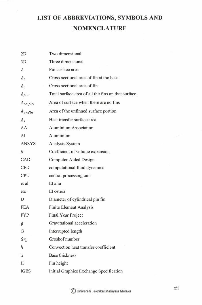
LIST OF ABBREVIATIONS, SYMBOLS AND
NOMENCLATURE
Two dimensional
Three dimensional
Fin surface area
Cross-sectional area of fin at the base
Cross-sectional area of fin
Total surface area of all the fins on that surface
Area of surface when there are no fins
Area of the unfinned surface portion
Heat transfer surface area
Aluminium Association
Aluminium
Analysis System
Coefficient of volume expansion
Computer-Aided Design
computational fluid dynamics
central processing unit
Et alia
Et cetera
Diameter of cylindrical pin fin
Finite Element Analysis
Final Year Project
Gravitational acceleration
Interrupted length
Groshof number
Convection heat transfer coefficient
Base thickness
Fin height
Initial Graphics Exchange Specification
© Universiti Teknikal Malaysia Melaka Xll

k
K
L
m
mm
n
Nu
q
Q
r'2conv
Qfin
Qfin,max
r'2no fin
r'2rad
r'2total,fin
r'2total,no fin
RaL
Pr
s
!:iT
v
w
w
Thermal conductivity
Kelvin
Base length
Corrected length
Characteristic length of the geometry
Parameter in theoretical fin efficiency
meter
millimeter
Number of fins
Nusselt number
Heat flux
Heat flux rate
Rate of heat transfer by convection
Actual heat transfer rate from the fin
Ideal heat transfer rate from the fin if the entire fin were at base
temperature
Rate of heat transfer if no fin is attached to the surface
Rate of heat transfer by radiation
Total rate of heat transfer from a finned surface
Total rate of heat transfer from unfinned surface
Rayleigh number
Prandtl number
Fin spacing
Fin thickness
Base temperature
Film temperature
Surface Temperature
Ambient temperature
temperature difference across the medium
Kinematic viscosity of the fluid
Fin length
Sink width
© Universiti Teknikal Malaysia Melaka Xlll
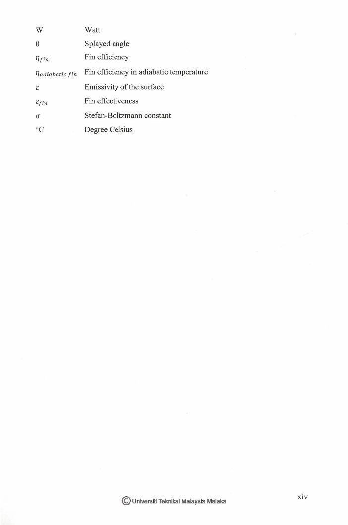
VI V/att
8 Splayed angle
TJ fin Fin efficiency
T/adiabatic fin Fin efficiency in adiabatic temperature
E Emissivity of the surface
Efin Fin effectiveness
a Stefan-Boltzmann constant
°C Degree Celsius
© Universiti Teknikal Malaysia Melaka XIV
1
This chapter introduces the general idea of this project and provides the problem
statement, objectives, and project scope. This chapter also provides a report
organization to briefly introduce about the purpose of all the generated chapters.
1.1 Background
Nowadays, the new wave of computer technology makes a crucial impact on modern
world. Desktop computer is widely employed in state-of-the-art industry and more
data are capable to be processed with a tremendous speed due to rapid development
of IT. This capability not only leads to higher density of heat and increases heat
dissipation of personal computer, but also causes the temperature of central
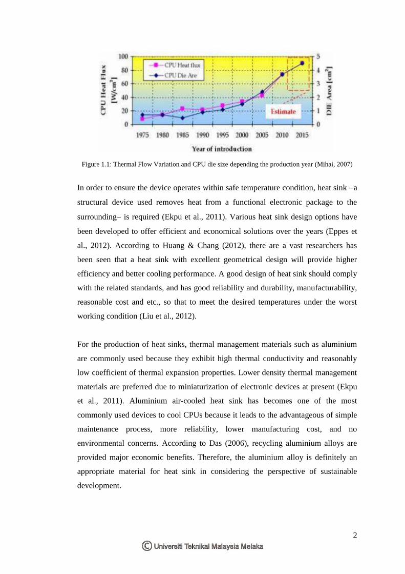
processing unit (CPU) rises (Mohan & Govindarajan, 2010). Based on Figure 1.1,
the density of thermal flow is highly needed to concern, no matter what is the
manufactured CPU (Mihai, 2007). The high temperature of CPU seriously increases
its failure mode and also shortens its own life (Mohan & Govindarajan, 2010).
INTRODUCTION
CHAPTER 1
2
Figure 1.1: Thermal Flow Variation and CPU die size depending the production year (Mihai, 2007)
In order to ensure the device operates within safe temperature condition, heat sink a
structural device used removes heat from a functional electronic package to the
surrounding is required (Ekpu et al., 2011). Various heat sink design options have
been developed to offer efficient and economical solutions over the years (Eppes et
al., 2012). According to Huang & Chang (2012), there are a vast researchers has
been seen that a heat sink with excellent geometrical design will provide higher
efficiency and better cooling performance. A good design of heat sink should comply
with the related standards, and has good reliability and durability, manufacturability,
reasonable cost and etc., so that to meet the desired temperatures under the worst
working condition (Liu et al., 2012).
For the production of heat sinks, thermal management materials such as aluminium
are commonly used because they exhibit high thermal conductivity and reasonably
low coefficient of thermal expansion properties. Lower density thermal management
materials are preferred due to miniaturization of electronic devices at present (Ekpu
et al., 2011). Aluminium air-cooled heat sink has becomes one of the most
commonly used devices to cool CPUs because it leads to the advantageous of simple
maintenance process, more reliability, lower manufacturing cost, and no
environmental concerns. According to Das (2006), recycling aluminium alloys are
provided major economic benefits. Therefore, the aluminium alloy is definitely an
appropriate material for heat sink in considering the perspective of sustainable
development.
3
This paper focuses on three types of fin designs such as plate finned heat sink, in-line
strip finned heat sink, and splayed pin finned heat sink, which are the common types
used in the computer for CPU cooling. 3D SolidWorks models for the three fin
designs are presented and temperature distribution and total heat flux are predicted
for the heat sinks in a range of temperature using finite element analysis which is
implemented using ANSYS software. This project is proposed an improved design of
finned heat sink and it is compared to the other finned heat sink. Therefore, a fin
design which has the most excellent in thermal performance is obtained at the end of
this project. The aluminium alloy 6063 is used as material of fins, but the addition of
other metals in the amounts commonly used in aluminium alloys does not
appreciably change the density (EAA, 1994).
1.2 Problem Statement
Computers continue to get faster via smaller and more intricate circuitry, which
generates mass amounts of heat. Heat given off by processors must be dissipated to
prevent the electrical equipments operate slowly or malfunction. According to
Gurrum et al. (2004), heat dissipation rates for computer CPUs may increase as high
as 180 W for the next few years and as high as 288 W by the year 2016.
The finned heat sinks work under uncertainty conditions with fluctuated temperature
and heat capacity. Electrical equipments will failure in operation as the heat transfer
rate of finned heat sinks is much lower compared to the total heat released from CPU.
This had become the main problem which arises in designing fins with a desired
material. Therefore, thermal analysis on the fin designs are required to test the
thermal performance of fins under certain range of ambient temperature, as well as
the factor of safety and fin efficiency are analyzed under steady state and transient
condition respectively.
In addition to the present world, sustainable development of the environment has
become the pivotal political and social issue to solve the problems of destruction the
environment and natural resources. The selection of recyclable material for fin could
4
be a critical part, but the integration of appropriate material with the fin designs and
analyzed under uncertainty heat capacity has becomes more challenging. Therefore,
a high thermal conductivity material is required so the fins can resist under any
temperature.
1.3 Objectives
The objectives of this project are
a) To investigate the design parameters of fins.
b) To analyze the uncertainty heat capacity for fins using engineering analysis
software.
c) To design of fins under uncertainty heat capacity.
1.4 Scope of Project
This project focuses the design of finned heat sink used in the cooling of central
processing unit (CPU) for computer. There are many different designs of finned heat
sink commercially available in the market, but only three existing designs which are
the heat sinks with plate fins, in-line strip fins, and splayed pin fins are investigated
under natural convection. Aluminium alloy 6063-O is used as the only and desirable
material for the three fin designs for further simulation and analysis.
The performance of a heat sink is affected by various parameters such as fin shapes,
fin arrangement or alignment; base length (L), fin height (H), fin thickness (t), sink
width (W), fin spacing (s), base thickness (h), fin length (w) and number of fins (n)
which all are measured in unit of millimeter (mm). These parameters can considered
as the performance improvement paths for the selected heat sinks. Many design
constraints such as heat transfer surface area (A), heat transfer coefficient (h), ambient
temperature (T∞), surface temperature of fin (TS), and thermal conductivity (k) are also
5
explored and attention is focused on the selection of fin designs under uncertainty heat
capacity.
Three dimensional (3D) fin design models are generated using SolidWorks 2010
software and the simulations are conducted with the aids of ANSYS software.
Thermal analysis is conducted respectively under steady state condition and transient
condition that involves conduction and convection phenomena.
Thermal analysis of the three fin models was first conducted under steady state
condition at different ambient temperature to analyze the temperature distribution,
total heat flux, and factor of safety of finned heat sink. The results from the
simulations are analyzed and discussed; therefore, the best among the three fin
models can be selected by weighted scoring method. Besides, an improved design of
finned heat sink is proposed based on the comparison of the candidate fin models.
The selected fin design and proposed fin design are then analyzed under transient
condition. This analysis is required to predict the temperature distribution and total
heat flux of the heat sink body which are vary with time. The results of simulation
for both fin models are analyzed and compared so that a fin design with the best
thermal performance is selected at the end of this project.
1.5 Project Organization
This report is divided into five different chapters which are completed within the
duration of one year. These chapters are briefly introduced and described at below:
(a) Chapter 1 - Introduction
Chapter 1 proposes an overview for the entire project and shows the systematic
plan to conduct this project. This chapter involves the project background,
problem statements, objectives, scope of project, project organization. The Gantt
chart illustrates the activity planning of FYP I and FYP II is attached at Appendix
A.

6
(b) Chapter 2 - Literature Review
Chapter 2 provides the explanations of fins used in the cooling of CPU in
computer, fin designs, design principles, heat capacity and the material used,
aluminium alloy 6063 is used for the fin designs. This chapter provides also the
reviews of the software, including SolidWorks 2010 and ANSYS software. The
information regarding to each element which includes introduction, properties,
and some applications are obtained from the past studies, journals, books and
articles to help in understanding more about the elements that involved in this
project and as the guidance for the project flow. Relevant methods used by other
researchers are reviewed and compared in order to act as guideline to solve the
problems and to achieve the objectives.
(c) Chapter 3 - Research Methodology
Chapter 3 is described the methodology used to solve the problems and to
achieve the objectives. A flow chart is generated with its descriptions to show the
process flow and methodology that used as a guideline for this project. In this
chapter, the relevant variables and elements are defined in detail together with the
engineering sketching of three different fin designs.
(d) Chapter 4 - Result and Discussion
Chapter 4 describes the implementation of the methodology which had proposed
in Chapter 3 to obtain three detail designs of fin and their accurate data through
the uses of design and analysis software. The results are then to be explained and
compared between each other using the relevant variables. The weighted scoring
method is implemented for the selection of design. Lastly, the best fin design is
selected based on the analysis and it is investigated and compared with proposed
design through simulation. Finally, only one with best performance is chosen.
(e) Chapter 5 - Conclusion
Chapter 5 is the last chapter which conclude the overall findings of the entire
project and the most excellent design of fins is obtained. This chapter provides
also the recommendation for future research.