Embed Size (px)
Citation preview

Operating instructions Binary level sensor
LMT
7060
52/0
0 06
/201
1
UK

2
Contents1 Preliminary note ���������������������������������������������������������������������������������������������������3
1�1 Symbols used ������������������������������������������������������������������������������������������������32 Safety instructions �����������������������������������������������������������������������������������������������33 Functions and features ����������������������������������������������������������������������������������������4
3�1 Application area ���������������������������������������������������������������������������������������������43�2 Restriction of the application area �����������������������������������������������������������������5
4 Function ���������������������������������������������������������������������������������������������������������������54�1 Measuring principle ���������������������������������������������������������������������������������������54�2 Processing of the measured signals ��������������������������������������������������������������54�3 Features of the unit ����������������������������������������������������������������������������������������54�4 Application examples �������������������������������������������������������������������������������������6
5 Installation������������������������������������������������������������������������������������������������������������65�1 Installation location / environment �����������������������������������������������������������������65�2 Mounting ��������������������������������������������������������������������������������������������������������7
5�2�1 Clamp adapter / adapter for pipes ��������������������������������������������������������85�2�2 Welding / screw-in adapter �������������������������������������������������������������������8
5�3 Notes on 3A compliant installation �����������������������������������������������������������������95�4 Note on the use in accordance with EHEDG �������������������������������������������������9
6 Electrical connection ������������������������������������������������������������������������������������������107 Operation �����������������������������������������������������������������������������������������������������������108 Maintenance, repair, disposal ����������������������������������������������������������������������������109 Scale drawing ���������������������������������������������������������������������������������������������������� 1110 Technical data ��������������������������������������������������������������������������������������������������1211 Notes on the regulation (EC) 1935/2004 ���������������������������������������������������������12

3
UK
1 Preliminary note1.1 Symbols used
► Instruction→ Cross-reference
Important note Non-compliance can result in malfunction or interference�Information Supplementary note�
2 Safety instructions• Please read the product description prior to set-up of the unit� Ensure that the
product is suitable for your application without any restrictions� • If the operating instructions or the technical data are not adhered to, personal
injury and/or damage to property can occur�• Installation, electrical connection, set-up, operation and maintenance of the
unit must only be carried out by qualified personnel authorised by the machine operator�
• The unit complies with the standard EN 61000-6-4� In domestic areas (EN 61000-6-3) the unit must be installed in closed metal tanks / pipes�
• For units the scope of validity cULus: The device shall be supplied from an isolating transformer having a secondary Listed fuse rated either a) max 5 amps for voltages 0~20 Vrms (0~28�3 Vp) or b) 100/Vp for voltages of 20~30 Vrms (28�3~42�4 Vp)�

4
3 Functions and featuresThe unit monitors the level of liquid, viscous and powdery media in tanks and pipes� It can be used for limit detection and run-dry protection�3.1 Application area• Suitable for food and hygienic areas due to food-grade materials and hygienic
installation possibilities�• Detection of almost all media, even extremely adhering (e�g� ketchup) or non-
conductive ones (e�g� vegetable oil)� In the following table you can find a selection of tested media and the corre-sponding recommended unit type� A detailed list is available at www�ifm�com�Medium LMT100 LMT110 Alcohol (40 % vol) ●Beer (lager) ●Butter ●CIP solution ● *)Chocolate (at approx� 40 °C) ●Grease ●Jam ●Ketchup ●Milk ●Non-dairy creamer ●Olive oil ●Remoulade ●Sugar (granulated sugar) ●Water (distilled) ●Water (tap water) ●Yogurt, natural ●
*) In the case of heavy wetting by CIP solution, the LMT110 switches as in the case of “medium detected”� OUT1 = ON und OUT2 = OFF (i�e� the cleaning operation is detected)� ► Always check whether the sensor is appropriate for the corresponding applications without restriction�

5
UK
• The unit can be operated at the following medium temperatures: - 0…85 °C (aqueous media)� - 0…100 °C (oils, fats and powdery media)�
• For a limited time (1 h) it can be used at 150 °C� Therefore it is suitable for all standard cleaning and sterilisation processes (CIP, SIP)�
• Tank pressure: -1…16 bar�3.2 Restriction of the application area• Not suitable for very abrasive media (e�g� quartz sand)�• For use in very aggressive media (strong acids and alkali):
► Firstcheckthecompatibilityoftheproductmaterials(→10Technicaldata).• Media which are very inhomogeneous separate from each other thus forming
separation layers (e�g� oil layer on water): ► Check the function by an application test�
4 Function4.1 Measuring principleThe unit operates to the impedance spectroscopy method� It evaluates the electri-cal behaviour of the media to be monitored in the frequency range between 50 and 200 MHz� The different media show characteristic behaviour� Also deposits or foam show significantly different behaviour� The presetting of the unit allows detec-tion of the presence of certain media; deposits or foam, however, are suppressed� 4.2 Processing of the measured signalsOutputs OUT1 and OUT2 complement each other:- no medium detected: OUT1 = OFF and OUT2 = ON� - medium detected: OUT1 = ON and OUT2 = OFF�
4.3 Features of the unit• Food-grade materials: 316L, PEEK�• Hygienic installation possibilities without dead band�• Approvals / conformities: FDA, EG 1935 / 2004, EHEDG, 3A, UL�• Status indication by yellow LED�• After application of the operating voltage immediately ready for operation� No
settings on the unit necessary�• Short response time: switching delay approx� 0�1 s�• Defined position of the cable outlet for angled sockets for use of ifm welding
adapters�
6
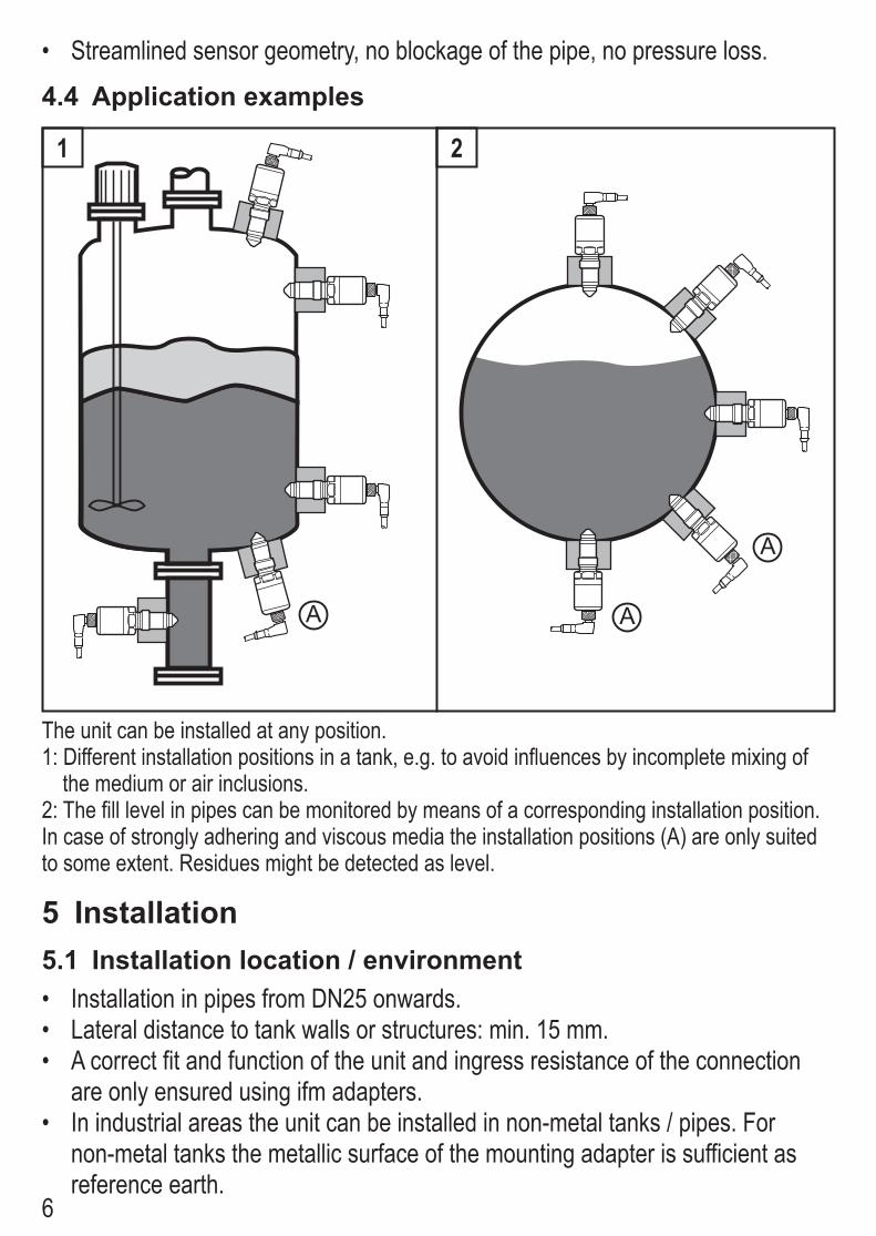
• Streamlined sensor geometry, no blockage of the pipe, no pressure loss�
4.4 Application examples
A A
A
1 2
The unit can be installed at any position�1: Different installation positions in a tank, e�g� to avoid influences by incomplete mixing of
the medium or air inclusions�2: The fill level in pipes can be monitored by means of a corresponding installation position�In case of strongly adhering and viscous media the installation positions (A) are only suited to some extent� Residues might be detected as level�
5 Installation5.1 Installation location / environment• Installation in pipes from DN25 onwards�• Lateral distance to tank walls or structures: min� 15 mm�• A correct fit and function of the unit and ingress resistance of the connection
are only ensured using ifm adapters� • In industrial areas the unit can be installed in non-metal tanks / pipes� For
non-metal tanks the metallic surface of the mounting adapter is sufficient as reference earth�

7
UK
• In domestic areas the unit must be installed in closed metal tanks / pipes�• Do not use additional sealing material (e�g� Teflon tape) at the probe tip (seal-
ing cone)�• Protect the probe tip against direct sunlight�
5.2 MountingThe unit is installed by means of a mounting adapter� The following components are available as accessories:Welding adapters G½ Version Order no�
ball E30055collar E30056
cylindrical for tanks E43300cylindrical for pipes E43301
Welding adapter G½ with 3A approval
cylindrical for tanks E43309cylindrical for pipes E43310
Mounting adapters G½ G ¾ E43302G 1 E43303
DIN11851 DN25 E43304DIN11851 DN40 E43305
Varivent D50 E43306Varivent D68 E43307
clamp 1-1,5“ ISO 2852 / DIN 32676 E33401clamp 2“ ISO 2852 / DIN 32676 E33402
DN25 SMS E33430Mounting adapter G½ with 3A approval
clamp 1-1,5“ ISO 2852 / DIN 32676 E43311clamp 2“ ISO 2852 / DIN 32676 E43312
Cover plug G½ for adapter E43308
8
5.2.1 Clamp adapter / adapter for pipes ► Slightly grease the thread of the sensor using a lubricating paste which is suit-able and approved for the application�
► Screw the unit into the adapter until it is hand-tight� Do not damage the sealing chamfers�
► Clamp sensor and adapter into a clamping device� Tighten the clamping device only slightly so that the adapter does not warp�
► Tighten the sensor using a spanner �Tightening torque: 20���25 Nm�
► Fix the unit + adapter to the process connection by means of a coupling nut, a clamp flange or the like�
5.2.2 Welding / screw-in adapter ► Ensure cleanliness of the sealing areas� Remove protective packaging only just before mounting� In case of damaged sealing areas replace the unit or the adapter�
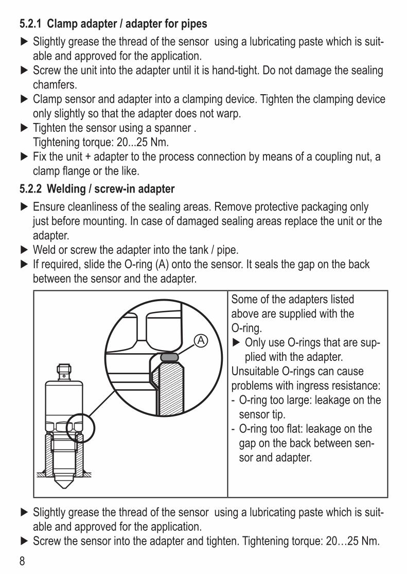
► Weld or screw the adapter into the tank / pipe� ► If required, slide the O-ring (A) onto the sensor� It seals the gap on the back between the sensor and the adapter�
A
Some of the adapters listed above are supplied with the O-ring�
► Only use O-rings that are sup-plied with the adapter�
Unsuitable O-rings can cause problems with ingress resistance: - O-ring too large: leakage on the sensor tip�
- O-ring too flat: leakage on the gap on the back between sen-sor and adapter�
► Slightly grease the thread of the sensor using a lubricating paste which is suit-able and approved for the application�
► Screw the sensor into the adapter and tighten� Tightening torque: 20…25 Nm�

9
UK
► After installation check the tank / pipe for ingress resistance�
5.3 Notes on 3A compliant installationThe unit has a 3A approval� It is only valid in conjunction with adapters with 3A approval(→tableabove).
The welding spot must comply with the 3-A standard 74-03, D6�1�4: "The minimum radii for fillets of welds in product contact surfaces shall be not less than 1/4 in� (6�35 mm) except that the minimum radii for such welds may be 1/8 in� (3�18 mm) when the thickness of one or both parts joined is less than 3/16 in� (4�76 mm)�"
Self-emptying must be ensured by an appropriate installation position (posi-tion 1���3)�The process connection must be provided with a self-emptying leakage port� This is ensured by using the adapterwith3Aapproval(→tableabove)�
5.4 Note on the use in accordance with EHEDGThe unit has an approval in accordance with EHEDG� When the unit is used in hygienic areas to EHEDG in conjunction with the above listed adapters, the follow-ing applies:
► Make sure that the sensors are integrated into the system in accordance with EHEDG�

10
6 Electrical connectionThe unit must be connected by a qualified electrician�The national and international regulations for the installation of electrical equipment must be adhered to�Voltage supply to EN 50178, SELV, PELV�
► Disconnect power� ► Connect the unit as follows:
4
L
L+2
1
32:4:
For information about available sockets/connectors see:www�ifm�com →Products→Accessories
7 OperationWhen the supply voltage has been applied, the unit is in the operating mode� It carries out its evaluation functions and switches the outputs�Operation indication by LED and output signals:
LED OUT1 OUT2unit ready for operation, no medium detected OFF OFF ONunit ready for operation, medium detected lights ON OFFno operating voltage OFF OFF OFFerror / failure flashes OFF OFF
8 Maintenance, repair, disposal ► From time to time check the probe cap for build-up and damage� Clean the unit if badly soiled In case of damage replace the unit�
► After removal and before reinstallation of the unit carefully clean the probe neck and the installation slot - especially the sealing cone - with appropriate meth-ods to ensure that it is resistant to ingress and without dead band�
► It is not possible to repair the unit�

11
UK
► After use dispose of the unit in an environmentally friendly way in accordance with the applicable national regulations�
► In case of returns ensure that the unit is free from soiling, especially of danger-ous and toxic substances� For transport only use appropriate packaging to avoid damage of the unit�
When changing the medium it might also be necessary to change the type ofunit(→3.1,table).
9 Scale drawing
1246
88
30 18
102
G 21LED
27
Dimensions in mm1: tightening torque 20���25 Nm
12
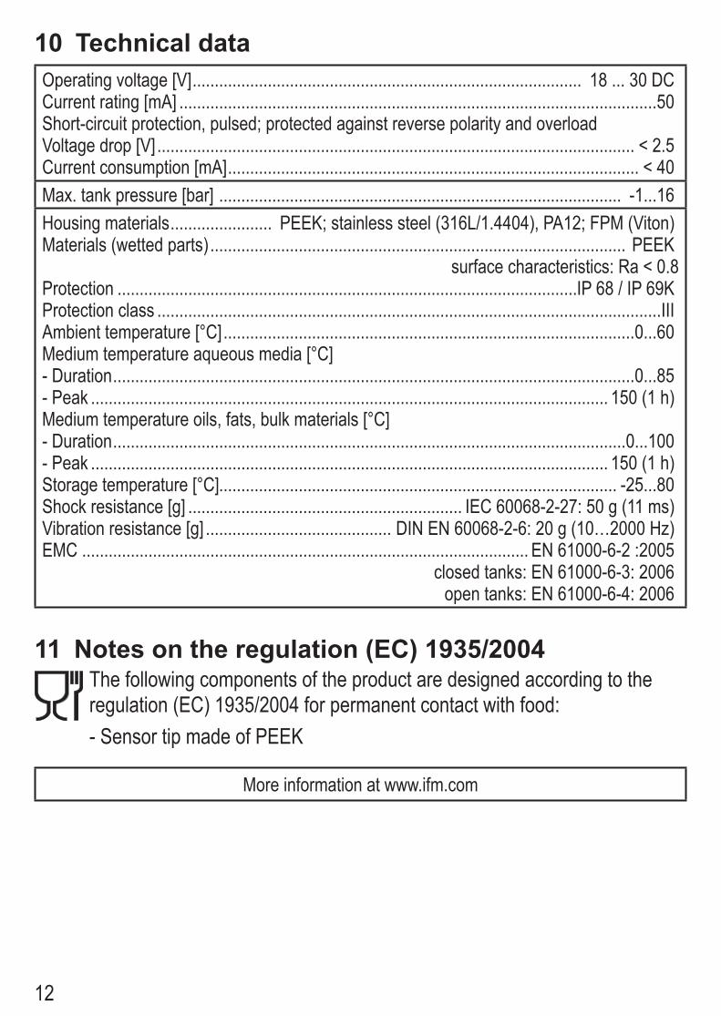
10 Technical dataOperating voltage [V] ���������������������������������������������������������������������������������������� 18 ��� 30 DCCurrent rating [mA] ������������������������������������������������������������������������������������������������������������50Short-circuit protection, pulsed; protected against reverse polarity and overloadVoltage drop [V] ������������������������������������������������������������������������������������������������������������ < 2�5Current consumption [mA] ��������������������������������������������������������������������������������������������� < 40Max� tank pressure [bar] ������������������������������������������������������������������������������������������� -1���16Housing materials ����������������������� PEEK; stainless steel (316L/1�4404), PA12; FPM (Viton)Materials (wetted parts) ���������������������������������������������������������������������������������������������� PEEK
surface characteristics: Ra < 0�8Protection ��������������������������������������������������������������������������������������������������������IP 68 / IP 69KProtection class ������������������������������������������������������������������������������������������������������������������IIIAmbient temperature [°C] ���������������������������������������������������������������������������������������������0���60Medium temperature aqueous media [°C]- Duration ����������������������������������������������������������������������������������������������������������������������0���85- Peak ��������������������������������������������������������������������������������������������������������������������� 150 (1 h)Medium temperature oils, fats, bulk materials [°C]- Duration ��������������������������������������������������������������������������������������������������������������������0���100- Peak ��������������������������������������������������������������������������������������������������������������������� 150 (1 h)Storage temperature [°C]������������������������������������������������������������������������������������������ -25���80Shock resistance [g] �������������������������������������������������������������� IEC 60068-2-27: 50 g (11 ms)Vibration resistance [g] ������������������������������������������ DIN EN 60068-2-6: 20 g (10…2000 Hz)EMC ����������������������������������������������������������������������������������������������������� EN 61000-6-2 :2005 closed tanks: EN 61000-6-3: 2006 open tanks: EN 61000-6-4: 2006
11 Notes on the regulation (EC) 1935/2004The following components of the product are designed according to the regulation (EC) 1935/2004 for permanent contact with food: - Sensor tip made of PEEK
More information at www�ifm�com