Embed Size (px)
Citation preview
LMU-42x0™
Hardware and Installation Guide
Plan the Installation
Verify Power, Ground and Ignition. Be sure to check each source (power, ground and ignition) to ensure that the proper signaling exists. This is typically accomplished with a multi-meter. Before drilling any holes or running any wires, decide where each hardware component will be located (LMU, antennas, peripherals, etc.). Be sure that the cables to the LMU are not bent or constricted in any way. Also make sure that the LMU is kept free from direct exposure to the elements (sun, heat, rain, moisture etc...). Be advised that an installation that violates the environmental specifications of the LMU will void the warranty. The best way to ensure a trouble-free installation is to consider your options and make some decisions before you start. Take a look at the vehicle and determine how to best install the LMU for the following purposes:
Accurate data gathering and simulation of how customers actually use your solution Ongoing monitoring and maintenance of LMU equipment Accidental or intentional alteration of the equipment or cable connections
The following sections cover some of the issues to consider when planning your LMU installation.
•
••

Size and Placement of LMU Unit
The dimensions of the LMU should be taken into account, particularly when installing in a vehicle: Whether you intend to place the LMU under a seat or into a cavity behind the vehicle’s interior molded trim, be sure the LMU will fit before drilling any holes or running cable
Be certain that the cables running to the LMU will not be bent or constricted. Damage to the cables may impede the LMU’s performance. Be certain that the installation point will not violate any of the LMU’s environmental specification (temperature, moisture, etc…) as improper installation of the LMU may void the warranty.
Typical installations will place the LMU under the vehicle dash board, or in the trunk. Make sure you can get access to the unit afterwards as under some circumstances it may be necessary to add additional wiring or connections to the LMU. Status LED lights on the front of the LMU unit can provide valuable information about the operation of the LMU. When feasible, attempt to install the LMU in such a way that these lights can be seen with reasonable ease. You may find it useful to be able to view the LEDs periodically to make sure that the LMU is operating properly. If at any time you should encounter a problem with the LMU, you may need to read the LEDs in order to troubleshoot the problem. If you cannot fix the LMU yourself, you will need to provide the LED information to CalAmp customer support. The RF cables which are provided for connecting to the LMU antennas should be used at the length provided. Do not cut cables. Instead, coil any excess cable length, making sure not to crimp or flatten the antenna cable. The LMU unit must be located where it will not be exposed to moisture or water. In a typical installation inside a vehicle this is not commonly thought to be a concern; however, it might be best to avoid locating the LMU below a car’s cup holders, or where rain might easily splash into the compartment when a door is opened. Typically, the LMU should be placed under the passenger seat or dashboard of the vehicle. LMUs with internal antennas should be placed to maximize their GPS performance. A typical location include under the dash close to the front wind-shield. Attach the LMU to the solid body of the vehicle, not to plastic panels. The LMU can be placed out of sight by removing interior trim and molding to expose available space, then replacing the trim once the LMU is in place.
•
•
Placement of Antennas
There are effectively three options for placements of an antenna:
Roof-mount (magnetic or thru-hole) Glass-mount Covert (e.g. under the seat, dash, etc…)
Comm. Antenna Placement Guidelines The Comm. Antenna must be located at least 20cm away from vehicle passengers, other personnel, or bystanders in order to comply with FCC radio frequency exposure limits. Typically, the Comm. antenna used by the LMU for wireless service is a standard 3-dB gain whip. It mounts with standard mounts (i.e. thru-hole, magnetic mount or peel and stick) and requires a ground plane to work properly. If possible, it should be located at least 3 feet from the GPS antenna. Ensure that the cable does not get crushed during installation. Please note that the antennas provided by CalAmp combine both the GPS and Comm. portions.
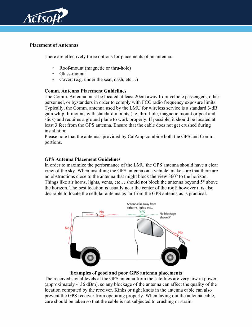
GPS Antenna Placement Guidelines In order to maximize the performance of the LMU the GPS antenna should have a clear view of the sky. When installing the GPS antenna on a vehicle, make sure that there are no obstructions close to the antenna that might block the view 360° to the horizon. Things like air horns, lights, vents, etc… should not block the antenna beyond 5° above the horizon. The best location is usually near the center of the roof; however it is also desirable to locate the cellular antenna as far from the GPS antenna as is practical.
Examples of good and poor GPS antenna placements
The received signal levels at the GPS antenna from the satellites are very low in power (approximately -136 dBm), so any blockage of the antenna can affect the quality of the location computed by the receiver. Kinks or tight knots in the antenna cable can also prevent the GPS receiver from operating properly. When laying out the antenna cable, care should be taken so that the cable is not subjected to crushing or strain.
•••

Placement of Combination and Internal Antennas When dealing with combination antennas, it is more important to considered GPS performance over Comm. performance. GPS signal strengths are much lower than those typically seen by cellular networks supported by the LMU. In order to maximize the performance the LMU should have a clear view of the sky as possible. When installing the GPS antenna in a vehicle, make sure that there are as few obstructions as possible close to the LMU that might block the view 360° to the horizon. As with stand-alone GPS antennas, nothing should not block the combination antenna beyond 5° above the horizon with the best location being near the center of the roof. For more covert installs, directly under the front or rear-windshields are also acceptable.
Examples of Good (Green), OK (Yellow) and Poor (Red) combo antenna placements
Examples OK (Yellow) and Poor (Red) internal antenna placements

Connect power, ignition, and ground.
The power input (red wire) must be connected to a constant (un-switched) +12 VDC or +24 VDC supply; preferably, connected directly to the vehicle battery terminal or as close to it as possible. This connection point should be fuse protected to not more than 5 Amps. The ignition input (white wire) must be connected to the vehicle ignition or another appropriate key operated line, such as ACCESSORY, ensuring that power to the ignition wire is available only when the vehicle ignition is on. The ground line (black wire) must be connected to chassis ground. Failure to connect these lines in the manner described may result in discharge of the vehicle battery. For best results, it is strongly recommended that the LMU connection be on its own circuit. Connect the power input directly to the vehicle battery if possible and protect the circuit with an inline fuse. If you must connect through the fuse box, use standard commercial wiring practices to create a permanent installation rather than using press-in fuse clips or other temporary measures. DO NOT connect the power cable to the LMU at this time.
Place the GPS antenna.
The GPS antenna must have a clear view of the sky. Mount the GPS antenna on the vehicle’s highest point (for example, the roof of a car). Make sure that there are no obstructions close to the antenna that might block the view 360° to the horizon. Air horns lights, vents, etc... Should not block the antenna beyond 5° above the horizon. Kinks or knots in the antenna cable can prevent the GPS receiver from operating properly. When laying out the antenna cable, take care that the cable is not subjected to crushing or strain. The ideal location is typically near the center of the vehicle’s roof. However, it is also desirable to locate the cellular antenna as far from the GPS antenna as possible.
GPS Antenna Location
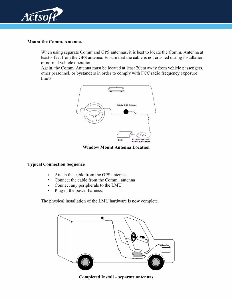
Mount the Comm. Antenna.
When using separate Comm and GPS antennas, it is best to locate the Comm. Antenna at least 3 feet from the GPS antenna. Ensure that the cable is not crushed during installation or normal vehicle operation. Again, the Comm. Antenna must be located at least 20cm away from vehicle passengers, other personnel, or bystanders in order to comply with FCC radio frequency exposure limits.
Window Mount Antenna Location
Typical Connection Sequence
Attach the cable from the GPS antenna. Connect the cable from the Comm.. antenna Connect any peripherals to the LMU Plug in the power harness.
The physical installation of the LMU hardware is now complete.
Completed Install – separate antennas
••••

Completed Install - Internal antennas
Power Connector
The LMU-42x0™ uses a 4 pin Molex 43045-0402 connector as its power connection. The pin out is as follows:
Pin SignalName Description 5C888
Color
Inputor
Output1 VIN Power Red Power / Input 2 GND Ground Black Ground
3 ADC1 Analog to Digital Input 1 Green Input
4 INPUT 0 Input 0 / Ignition Sense – Digital
Input White Input
LMU-42x0™ Header (looking into LMU)

I/O Connector
The LMU-42x0™’s features expanded I/O capabilities via its 22-Pin Molex 43045-2202 connector. Its pin-out is as follows:
Pin SignalName Description 5C889
ColorInput or Output
1 Input 1 Input 1 – Digital Input Blue Input 2 Input 2 Input 2 – Digital Input Orange Input 3 Input 3 Input 3 – Digital Input Violet Input 4 Input 4 Input 4 – Digital Input Gray Input 5 Input 5 Input 5 – Digital Input Green & White Input 6 Input 6 Input 6 – Digital Input Blue & White Input 7 Input 7 Input 7 – Digital Input Black & White Input 8 1BB T Data 1 Bit Bus Data (T) Green & Black Input/Output 9 1BB GND 1 Bit Bus Ground Black Ground 10 1 BB R Data 1 Bit Bus Data (R) Orange & Black Input/Output 11 1 BB Gnd 1 Bit Bus Ground Black Ground
12 Output 0 Output 0 - Starter Disable Relay Driver Green Output
13 Output 1 Output 1 - Digital Output Brown Output 14 Output 2 Output 2 - Digital Output Yellow Output
15 Output 3 Output 3 - Digital Output Blue & White & Orange Output
16 Output 4 Output 4 - Digital Output Green & Black & Orange Output
17 Output 5 - LED Output 5 - LED 1 Driver Red & Green Output
18 Output 6 - LED Output 6 - LED 2 Driver Orange & Green Output
19 ADC 2 Analog to Digital Input 2 Black & Red Input 20 ADC 3 Analog to Digital Input 3 White & Red Input 21 ADC 4 Analog to Digital Input 4 Orange & Red Input 22 ADC 5 Analog to Digital Input 5 Blue & Red Input
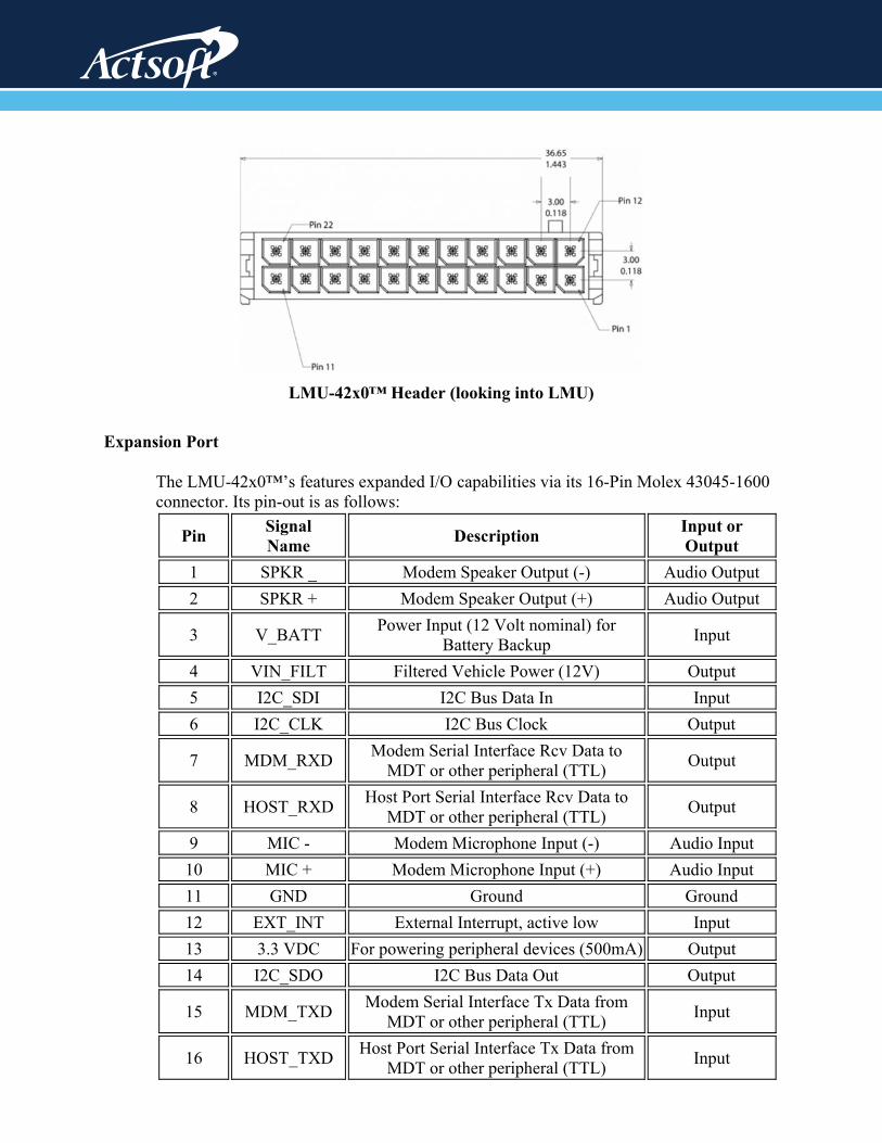
LMU-42x0™ Header (looking into LMU)
Expansion Port
The LMU-42x0™’s features expanded I/O capabilities via its 16-Pin Molex 43045-1600 connector. Its pin-out is as follows:
Pin SignalName Description Input or
Output1 SPKR _ Modem Speaker Output (-) Audio Output 2 SPKR + Modem Speaker Output (+) Audio Output
3 V_BATT Power Input (12 Volt nominal) for Battery Backup Input
4 VIN_FILT Filtered Vehicle Power (12V) Output 5 I2C_SDI I2C Bus Data In Input 6 I2C_CLK I2C Bus Clock Output
7 MDM_RXD Modem Serial Interface Rcv Data to MDT or other peripheral (TTL) Output
8 HOST_RXD Host Port Serial Interface Rcv Data to MDT or other peripheral (TTL) Output
9 MIC - Modem Microphone Input (-) Audio Input 10 MIC + Modem Microphone Input (+) Audio Input 11 GND Ground Ground 12 EXT_INT External Interrupt, active low Input 13 3.3 VDC For powering peripheral devices (500mA) Output 14 I2C_SDO I2C Bus Data Out Output
15 MDM_TXD Modem Serial Interface Tx Data from MDT or other peripheral (TTL) Input
16 HOST_TXD Host Port Serial Interface Tx Data from MDT or other peripheral (TTL) Input
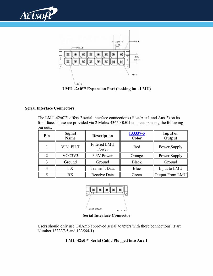
LMU-42x0™ Expansion Port (looking into LMU)
Serial Interface Connectors
The LMU-42x0™ offers 2 serial interface connections (Host/Aux1 and Aux 2) on its front face. These are provided via 2 Molex 43650-0501 connectors using the following pin outs.
Pin SignalName Description 133337-5
ColorInput or Output
1 VIN_FILT Filtered LMU Power Red Power Supply
2 VCC3V3 3.3V Power Orange Power Supply 3 Ground Ground Black Ground 4 TX Transmit Data Blue Input to LMU 5 RX Receive Data Green Output From LMU
Serial Interface Connector
Users should only use CalAmp approved serial adapters with these connections. (Part Number 133337-5 and 133564-1)
LMU-42x0™ Serial Cable Plugged into Aux 1
Expansion Interface
The expansion interface located on the back of the LMU-42x0™ via the 16-in Molex connector is used to extend I/O functions and provide serial access to the LMU-42x0™. It should only be used with CalAmp expansion harnesses. The available accessories are:
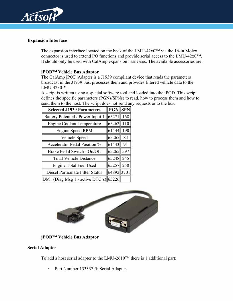
jPOD™ Vehicle Bus Adaptor The CalAmp jPOD Adapter is a J1939 compliant device that reads the parameters broadcast in the J1939 bus, processes them and provides filtered vehicle data to the LMU-42x0™. A script is written using a special software tool and loaded into the jPOD. This script defines the specific parameters (PGNs/SPNs) to read, how to process them and how to send them to the host. The script does not send any requests onto the bus.
Selected J1939 Parameters PGN SPN Battery Potential / Power Input 1 65271 168
Engine Coolant Temperature 65262 110 Engine Speed RPM 61444 190
Vehicle Speed 65265 84 Accelerator Pedal Position % 61443 91 Brake Pedal Switch - On/Off 65265 597
Total Vehicle Distance 65248 245 Engine Total Fuel Used 65257 250
Diesel Particulate Filter Status 64892 3701DM1 (Diag Msg 1 - active DTC’s) 65226
jPOD™ Vehicle Bus Adaptor
Serial Adapter
To add a host serial adapter to the LMU-2610™ there is 1 additional part:
Part Number 133337-5: Serial Adapter. •

I/O Descriptions
The LMU-42x0™ provides the following inputs and outputs (I/O): Digital Inputs Input 0: Ignition Sense (Always biased low) Input 1: Generic Digital Input (Biased high or low/ S-158 Bit 1) NOTE: Shared with Output 1. Function selection controlled by S-159 Input 2: Generic Digital Input (Biased high or low/ S-158 Bit 2) NOTE: Shared with Output 2. Function selection controlled by S-159 Input 3: Generic Digital Input (Biased high or low/ S-158 Bit 3) Input 4: Generic Digital Input (Biased high or low/ S-158 Bit 4) Input 5: Generic Digital Input (Biased high or low/ S-158 Bit 5) Input 6: Generic Digital Input (Fixed bias high) Input 7: Generic Digital Input (Fixed bias high) Input 8: Motion Sensor Analog to Digital Inputs A/D 0: External Power Supply Monitor A/D 1: Generic External Analog to Digital Input A/D 2: Generic External Analog to Digital Input A/D 3: Generic External Analog to Digital Input A/D 4: Generic External Analog to Digital Input A/D 5: Generic External Analog to Digital Input A/D 6: <TBD> A/D 7: GPS Antenna Monitor Outputs: Output 0: Standard Open Collector Relay Output Output 1: Standard Open Collector Relay Output Output 2: Standard Open Collector Relay Output Output 3: Standard Open Collector Relay Output Output 4: Standard Open Collector Relay Output LED Drivers Output 5: Standard LED Driver Output 6: Standard LED Driver iButton / 1 Bit Bus iButton ID Support 1Wire bus with current boost for temperature sensors

Ignition and Inputs
The LMU-42x0™ provides up to 7 inputs. These inputs are protected from typical vehicle transients and can be directly connected to most vehicle level logical inputs from 4 volts up to the vehicle power input level (typically 12 VDC). Their input impedance is approximately 10kΩ. One of these inputs is dedicated to sensing the vehicle’s ignition status to provide for flexible power management. The other two inputs may be used to sense vehicle inputs such as cooling unit operation, a hidden driver “Panic” switch, taxi on-duty/off-duty meter status or many others. The ignition input is pulled to ground through the 10k resistance, where the other inputs can be configured to be normally High (i.e. pulled to +12v through a 10k resistor) or Low (i.e. pulled to ground through a 10k resistor). The diagrams below show how to connect the inputs in both a high- and low-biased configuration:

Outputs
The LMU’s and ioPOD;s outputs are designed to drive external relays. These outputs provide a high-current, open-collector driver that can sink up to 150 mA each. These drivers may be used to drive external relays that can then control vehicle functions such as door locks, fuel shut-off valves, sirens and lights. If additional current is required to drive the relays, external circuitry can be added to source the current. This diagram is a typical use of an output to drive a relay.
Sample Relay Wiring
Status LEDs
The LMU-42x0™ is equipped with two Status LEDs, one for GPS and one for COMM (wireless network status). The LEDs use the following blink patterns to indicate service: LED #1 (Comm LED - Orange) Definitions
1 DEL noitidnoC ffO ffO medoM
Comm On - Searching Slow Blinking gniknilB tsaF elbaliavA krowteN
Registered but no Inbound Acknowledgement Alternates from Solid to Fast Blink every 1s
Registered and Received Inbound Acknowledgement Solid
LED #2 (GPS LED - Yellow) Definitions Condition LED 2 GPS Off Off GPS On Slow Blinking
GPS Time Sync Fast Blinking GPS Fix Solid