Embed Size (px)
Citation preview
Finder™ Wireless Location System
AnyPhone ™ LMU 850 / 1900 MHz Dual Band Installation Guide
7221-1862-0000Release 9.1.3 Revision D
February, 2006

COPYRIGHTS
© 2006, TruePosition, Inc. All Rights Reserved
TRADEMARKS
TruePosition is a registered trademark in the United States. TruePosition together with the TruePosition logo is a registered trademark in other countries. iFind, Finder, AnyPhone, ServiceGate, WideFind, ETS, TrueNorth, BSync, and SCOUT are trademarks of TruePosition Inc.
“Anyphone, Anywhere” is a service mark of TruePosition, Inc.
Other brands and their products are registered trademarks or trademarks of their respective holders and should be noted as such.
CONFIDENTIALITY
This document and the information contained herein is the proprietary and confidential information of TruePosition, Inc. It is provided under nondisclosure agreement and may not be reproduced or used for purposes outside the scope of such agreement.
WARRANTY
TruePosition provides this document “as is” without warranty of any kind, express or implied, including but not limited to the implied warranties of merchantability or fitness for a particular purpose. In no event shall TruePosition be liable for any damages of any kind, arising out of or related to the use or inability to use this document, even if TruePosition has been advised of the possibility thereof.
iii
Contents
1. INTRODUCTION . . . . . . . . . . . . . . . . . . . . . . . . . . . . . . . . . . . . . . . . . . . . . . . . . . . . . . . . . . . . . . . . . . 1-1
1.1. Purpose . . . . . . . . . . . . . . . . . . . . . . . . . . . . . . . . . . . . . . . . . . . . . . . . . . . . . . . . . . . . . . . . . . . . . . . . . . . .1-11.2. What’s New in This Document . . . . . . . . . . . . . . . . . . . . . . . . . . . . . . . . . . . . . . . . . . . . . . . . . . . . . . . . .1-11.3. Organization of the Document . . . . . . . . . . . . . . . . . . . . . . . . . . . . . . . . . . . . . . . . . . . . . . . . . . . . . . . . .1-31.4. Document Conventions . . . . . . . . . . . . . . . . . . . . . . . . . . . . . . . . . . . . . . . . . . . . . . . . . . . . . . . . . . . . . . .1-4
1.4.1. Writing Conventions . . . . . . . . . . . . . . . . . . . . . . . . . . . . . . . . . . . . . . . . . . . . . . . . . . . . . . . . . . . . . . .1-41.4.2. Admonishments . . . . . . . . . . . . . . . . . . . . . . . . . . . . . . . . . . . . . . . . . . . . . . . . . . . . . . . . . . . . . . . . . .1-6
1.5. Applicable Documents . . . . . . . . . . . . . . . . . . . . . . . . . . . . . . . . . . . . . . . . . . . . . . . . . . . . . . . . . . . . . . . .1-71.6. If You Need Help . . . . . . . . . . . . . . . . . . . . . . . . . . . . . . . . . . . . . . . . . . . . . . . . . . . . . . . . . . . . . . . . . . . .1-7
2. Finder WLS OVERVIEW . . . . . . . . . . . . . . . . . . . . . . . . . . . . . . . . . . . . . . . . . . . . . . . . . . . . . . . . . . . .2-1
2.1. Finder WLS Overview . . . . . . . . . . . . . . . . . . . . . . . . . . . . . . . . . . . . . . . . . . . . . . . . . . . . . . . . . . . . . . . .2-12.2. LMU System Description . . . . . . . . . . . . . . . . . . . . . . . . . . . . . . . . . . . . . . . . . . . . . . . . . . . . . . . . . . . . . .2-5
3. DUAL BAND LMU FRONT PANEL . . . . . . . . . . . . . . . . . . . . . . . . . . . . . . . . . . . . . . . . . . . . . . . . . . . .3-1
3.1. Introduction . . . . . . . . . . . . . . . . . . . . . . . . . . . . . . . . . . . . . . . . . . . . . . . . . . . . . . . . . . . . . . . . . . . . . . . . .3-13.2. Front Panel Description . . . . . . . . . . . . . . . . . . . . . . . . . . . . . . . . . . . . . . . . . . . . . . . . . . . . . . . . . . . . . . .3-1
3.2.1. Front Panel Description . . . . . . . . . . . . . . . . . . . . . . . . . . . . . . . . . . . . . . . . . . . . . . . . . . . . . . . . . . . .3-2
4. DUAL BAND LMU SPECIFICATIONS . . . . . . . . . . . . . . . . . . . . . . . . . . . . . . . . . . . . . . . . . . . . . . . . . .4-1
4.1. Introduction . . . . . . . . . . . . . . . . . . . . . . . . . . . . . . . . . . . . . . . . . . . . . . . . . . . . . . . . . . . . . . . . . . . . . . . . .4-14.2. Environmental . . . . . . . . . . . . . . . . . . . . . . . . . . . . . . . . . . . . . . . . . . . . . . . . . . . . . . . . . . . . . . . . . . . . . . .4-14.3. Electrical . . . . . . . . . . . . . . . . . . . . . . . . . . . . . . . . . . . . . . . . . . . . . . . . . . . . . . . . . . . . . . . . . . . . . . . . . . .4-24.4. Dimensions . . . . . . . . . . . . . . . . . . . . . . . . . . . . . . . . . . . . . . . . . . . . . . . . . . . . . . . . . . . . . . . . . . . . . . . . .4-24.5. RF Input . . . . . . . . . . . . . . . . . . . . . . . . . . . . . . . . . . . . . . . . . . . . . . . . . . . . . . . . . . . . . . . . . . . . . . . . . . .4-34.6. Radiated Emissions . . . . . . . . . . . . . . . . . . . . . . . . . . . . . . . . . . . . . . . . . . . . . . . . . . . . . . . . . . . . . . . . . . .4-3
5. DUAL-BAND LMU PRE-INSTALLATION . . . . . . . . . . . . . . . . . . . . . . . . . . . . . . . . . . . . . . . . . . . . . . .5-1
5.1. Overview . . . . . . . . . . . . . . . . . . . . . . . . . . . . . . . . . . . . . . . . . . . . . . . . . . . . . . . . . . . . . . . . . . . . . . . . . . .5-15.2. Vital Information . . . . . . . . . . . . . . . . . . . . . . . . . . . . . . . . . . . . . . . . . . . . . . . . . . . . . . . . . . . . . . . . . . . . .5-15.3. Constraints . . . . . . . . . . . . . . . . . . . . . . . . . . . . . . . . . . . . . . . . . . . . . . . . . . . . . . . . . . . . . . . . . . . . . . . . . .5-3
5.3.1. Mounting Constraints . . . . . . . . . . . . . . . . . . . . . . . . . . . . . . . . . . . . . . . . . . . . . . . . . . . . . . . . . . . . . .5-35.3.2. Cable Bend Radius . . . . . . . . . . . . . . . . . . . . . . . . . . . . . . . . . . . . . . . . . . . . . . . . . . . . . . . . . . . . . . . .5-55.3.3. Power Cables . . . . . . . . . . . . . . . . . . . . . . . . . . . . . . . . . . . . . . . . . . . . . . . . . . . . . . . . . . . . . . . . . . . .5-65.3.4. Ground Cables . . . . . . . . . . . . . . . . . . . . . . . . . . . . . . . . . . . . . . . . . . . . . . . . . . . . . . . . . . . . . . . . . . .5-75.3.5. Multicoupler Gain . . . . . . . . . . . . . . . . . . . . . . . . . . . . . . . . . . . . . . . . . . . . . . . . . . . . . . . . . . . . . . . . .5-75.3.6. GPS Parameters . . . . . . . . . . . . . . . . . . . . . . . . . . . . . . . . . . . . . . . . . . . . . . . . . . . . . . . . . . . . . . . . . .5-8
5.4. Select Cables . . . . . . . . . . . . . . . . . . . . . . . . . . . . . . . . . . . . . . . . . . . . . . . . . . . . . . . . . . . . . . . . . . . . . . . .5-85.4.1. RF Cables . . . . . . . . . . . . . . . . . . . . . . . . . . . . . . . . . . . . . . . . . . . . . . . . . . . . . . . . . . . . . . . . . . . . . . .5-85.4.2. GPS Cable . . . . . . . . . . . . . . . . . . . . . . . . . . . . . . . . . . . . . . . . . . . . . . . . . . . . . . . . . . . . . . . . . . . . . . .5-95.4.3. GSM Downlink Antenna Cables . . . . . . . . . . . . . . . . . . . . . . . . . . . . . . . . . . . . . . . . . . . . . . . . . . . .5-115.4.4. T1 Cables . . . . . . . . . . . . . . . . . . . . . . . . . . . . . . . . . . . . . . . . . . . . . . . . . . . . . . . . . . . . . . . . . . . . . . .5-115.4.5. V.35 Cables . . . . . . . . . . . . . . . . . . . . . . . . . . . . . . . . . . . . . . . . . . . . . . . . . . . . . . . . . . . . . . . . . . . . .5-12
iv
5.5. Equipment . . . . . . . . . . . . . . . . . . . . . . . . . . . . . . . . . . . . . . . . . . . . . . . . . . . . . . . . . . . . . . . . . . . . . . . . .5-155.5.1. Vital Equipment . . . . . . . . . . . . . . . . . . . . . . . . . . . . . . . . . . . . . . . . . . . . . . . . . . . . . . . . . . . . . . . . .5-155.5.2. Test Equipment . . . . . . . . . . . . . . . . . . . . . . . . . . . . . . . . . . . . . . . . . . . . . . . . . . . . . . . . . . . . . . . . . .5-165.5.3. Basic Tools . . . . . . . . . . . . . . . . . . . . . . . . . . . . . . . . . . . . . . . . . . . . . . . . . . . . . . . . . . . . . . . . . . . . .5-175.5.4. Miscellaneous Equipment . . . . . . . . . . . . . . . . . . . . . . . . . . . . . . . . . . . . . . . . . . . . . . . . . . . . . . . . . .5-205.5.5. Supporting Equipment . . . . . . . . . . . . . . . . . . . . . . . . . . . . . . . . . . . . . . . . . . . . . . . . . . . . . . . . . . .5-21
5.6. Final Pre-Installation Information . . . . . . . . . . . . . . . . . . . . . . . . . . . . . . . . . . . . . . . . . . . . . . . . . . . . . .5-215.7. Measurements . . . . . . . . . . . . . . . . . . . . . . . . . . . . . . . . . . . . . . . . . . . . . . . . . . . . . . . . . . . . . . . . . . . . . .5-23
6. DETERMINING THE GSM DOWNLINK ANTENNA CONFIGURATION . . . . . . . . . . . . . . . . . . . . . . . .6-1
7. INSTALL GPS AND EXTERNAL GSM DOWNLINK MONITOR ANTENNAS . . . . . . . . . . . . . . . . . . . . .7-1
7.1. Overview . . . . . . . . . . . . . . . . . . . . . . . . . . . . . . . . . . . . . . . . . . . . . . . . . . . . . . . . . . . . . . . . . . . . . . . . . . .7-17.2. Mounting Requirements . . . . . . . . . . . . . . . . . . . . . . . . . . . . . . . . . . . . . . . . . . . . . . . . . . . . . . . . . . . . . . .7-37.3. GPS Antenna Only Mounting Options . . . . . . . . . . . . . . . . . . . . . . . . . . . . . . . . . . . . . . . . . . . . . . . . . . .7-4
7.3.1. Ladder and Ice Bridge Mounts . . . . . . . . . . . . . . . . . . . . . . . . . . . . . . . . . . . . . . . . . . . . . . . . . . . . . . .7-47.3.2. Wall Mount GPS Antenna . . . . . . . . . . . . . . . . . . . . . . . . . . . . . . . . . . . . . . . . . . . . . . . . . . . . . . . . . .7-67.3.3. Strapped Pole Mount . . . . . . . . . . . . . . . . . . . . . . . . . . . . . . . . . . . . . . . . . . . . . . . . . . . . . . . . . . . . . .7-9
7.4. GPS with GSM Downlink Antenna Mounting Options . . . . . . . . . . . . . . . . . . . . . . . . . . . . . . . . . . . . .7-117.4.1. Wall Mounting . . . . . . . . . . . . . . . . . . . . . . . . . . . . . . . . . . . . . . . . . . . . . . . . . . . . . . . . . . . . . . . . . . .7-117.4.2. Ladder and Ice Bridge Mounting . . . . . . . . . . . . . . . . . . . . . . . . . . . . . . . . . . . . . . . . . . . . . . . . . . . .7-147.4.3. Pole Mounting . . . . . . . . . . . . . . . . . . . . . . . . . . . . . . . . . . . . . . . . . . . . . . . . . . . . . . . . . . . . . . . . . . .7-17
7.5. GPS Antenna Mount on an Ericsson BTS Cabinet RBS . . . . . . . . . . . . . . . . . . . . . . . . . . . . . . . . . . . .7-187.6. GPS Antenna Cable Connections . . . . . . . . . . . . . . . . . . . . . . . . . . . . . . . . . . . . . . . . . . . . . . . . . . . . . .7-21
7.6.1. Connecting Cables -- No Inline Amplifiers . . . . . . . . . . . . . . . . . . . . . . . . . . . . . . . . . . . . . . . . . . . .7-217.6.2. Connecting Cables Using an Inline Amplifier . . . . . . . . . . . . . . . . . . . . . . . . . . . . . . . . . . . . . . . . . .7-27
7.7. External GSM Downlink Antenna Cable Connections . . . . . . . . . . . . . . . . . . . . . . . . . . . . . . . . . . . . .7-347.7.1. Mounting the Surge Protector for the External GSM Downlink Antennas . . . . . . . . . . . . . . . . . .7-357.7.2. Connecting the Dual-band Diplexer . . . . . . . . . . . . . . . . . . . . . . . . . . . . . . . . . . . . . . . . . . . . . . . . .7-39
7.8. Connecting to an Existing GPS Antenna . . . . . . . . . . . . . . . . . . . . . . . . . . . . . . . . . . . . . . . . . . . . . . . .7-39
8. CHASSIS INSTALL . . . . . . . . . . . . . . . . . . . . . . . . . . . . . . . . . . . . . . . . . . . . . . . . . . . . . . . . . . . . . . . . .8-1
8.1. Rack Mounting and Installation . . . . . . . . . . . . . . . . . . . . . . . . . . . . . . . . . . . . . . . . . . . . . . . . . . . . . . . . .8-18.2. Wall Mount Installation . . . . . . . . . . . . . . . . . . . . . . . . . . . . . . . . . . . . . . . . . . . . . . . . . . . . . . . . . . . . . . .8-48.3. Cable Connections . . . . . . . . . . . . . . . . . . . . . . . . . . . . . . . . . . . . . . . . . . . . . . . . . . . . . . . . . . . . . . . . . . .8-6
8.3.1. RF Cable Connections . . . . . . . . . . . . . . . . . . . . . . . . . . . . . . . . . . . . . . . . . . . . . . . . . . . . . . . . . . . . .8-68.4. V.35 Cable Connection . . . . . . . . . . . . . . . . . . . . . . . . . . . . . . . . . . . . . . . . . . . . . . . . . . . . . . . . . . . . . . . .8-78.5. T1 Cable Connection . . . . . . . . . . . . . . . . . . . . . . . . . . . . . . . . . . . . . . . . . . . . . . . . . . . . . . . . . . . . . . . . .8-88.6. E1 Cable Connection . . . . . . . . . . . . . . . . . . . . . . . . . . . . . . . . . . . . . . . . . . . . . . . . . . . . . . . . . . . . . . . . .8-8
9. POWER CONNECTIONS . . . . . . . . . . . . . . . . . . . . . . . . . . . . . . . . . . . . . . . . . . . . . . . . . . . . . . . . . . . .9-1
9.1. Ground and Power Cable Connection . . . . . . . . . . . . . . . . . . . . . . . . . . . . . . . . . . . . . . . . . . . . . . . . . . . .9-19.2. Power the LMU . . . . . . . . . . . . . . . . . . . . . . . . . . . . . . . . . . . . . . . . . . . . . . . . . . . . . . . . . . . . . . . . . . . . . .9-3
10. DUAL BAND INTERNAL GSM DOWNLINK ANTENNA INSTALLATION . . . . . . . . . . . . . . . . . . . . . . 10-1
10.1. Introduction . . . . . . . . . . . . . . . . . . . . . . . . . . . . . . . . . . . . . . . . . . . . . . . . . . . . . . . . . . . . . . . . . . . . . . . .10-1

v
10.2. Mounting the GSM Downlink Antenna to the LMU . . . . . . . . . . . . . . . . . . . . . . . . . . . . . . . . . . . . . . .10-110.3. Installing the Rack-mounted GSM Downlink Antenna . . . . . . . . . . . . . . . . . . . . . . . . . . . . . . . . . . . . .10-410.4. Installing the Magnetically Mounted GSM Downlink Antenna . . . . . . . . . . . . . . . . . . . . . . . . . . . . . . .10-5
11. CONFIGURATION AND TEST OVERVIEW . . . . . . . . . . . . . . . . . . . . . . . . . . . . . . . . . . . . . . . . . . . . . . 11-1
11.1. Preparation . . . . . . . . . . . . . . . . . . . . . . . . . . . . . . . . . . . . . . . . . . . . . . . . . . . . . . . . . . . . . . . . . . . . . . . .11-1
12. SETTING UP THE PROCOMM CONSOLE INTERFACE . . . . . . . . . . . . . . . . . . . . . . . . . . . . . . . . . . . . 12-1
12.1. The ProComm Chat Window . . . . . . . . . . . . . . . . . . . . . . . . . . . . . . . . . . . . . . . . . . . . . . . . . . . . . . . . . .12-112.2. Standard Operating Mode . . . . . . . . . . . . . . . . . . . . . . . . . . . . . . . . . . . . . . . . . . . . . . . . . . . . . . . . . . . . .12-212.3. Operating Following A Reset . . . . . . . . . . . . . . . . . . . . . . . . . . . . . . . . . . . . . . . . . . . . . . . . . . . . . . . . .12-2
12.3.1. Reset without a T1/E1/V.35 Signal . . . . . . . . . . . . . . . . . . . . . . . . . . . . . . . . . . . . . . . . . . . . . . . . .12-212.3.2. Reset without a GPS Signal . . . . . . . . . . . . . . . . . . . . . . . . . . . . . . . . . . . . . . . . . . . . . . . . . . . . . . . .12-4
13. SET UP STRAPPING . . . . . . . . . . . . . . . . . . . . . . . . . . . . . . . . . . . . . . . . . . . . . . . . . . . . . . . . . . . . . . 13-1
13.1. Set the T1 Strapping . . . . . . . . . . . . . . . . . . . . . . . . . . . . . . . . . . . . . . . . . . . . . . . . . . . . . . . . . . . . . . . . .13-113.2. Set V.35 Parameters . . . . . . . . . . . . . . . . . . . . . . . . . . . . . . . . . . . . . . . . . . . . . . . . . . . . . . . . . . . . . . . . .13-313.3. Set E1 Connection . . . . . . . . . . . . . . . . . . . . . . . . . . . . . . . . . . . . . . . . . . . . . . . . . . . . . . . . . . . . . . . . . .13-513.4. Verify the SMLC Connection . . . . . . . . . . . . . . . . . . . . . . . . . . . . . . . . . . . . . . . . . . . . . . . . . . . . . . . . . .13-7
14. SET GPS PARAMETERS . . . . . . . . . . . . . . . . . . . . . . . . . . . . . . . . . . . . . . . . . . . . . . . . . . . . . . . . . . . 14-1
14.1. Preparation . . . . . . . . . . . . . . . . . . . . . . . . . . . . . . . . . . . . . . . . . . . . . . . . . . . . . . . . . . . . . . . . . . . . . . . .14-114.2. GPS Antenna Position . . . . . . . . . . . . . . . . . . . . . . . . . . . . . . . . . . . . . . . . . . . . . . . . . . . . . . . . . . . . . . .14-1
14.2.1. Set-Up and Configuring the GPS Handheld Device . . . . . . . . . . . . . . . . . . . . . . . . . . . . . . . . . . . . .14-214.2.2. Finding and Entering Longitude . . . . . . . . . . . . . . . . . . . . . . . . . . . . . . . . . . . . . . . . . . . . . . . . . . . .14-214.2.3. Finding and Entering Latitude . . . . . . . . . . . . . . . . . . . . . . . . . . . . . . . . . . . . . . . . . . . . . . . . . . . . . .14-214.2.4. Finding and Entering Altitude . . . . . . . . . . . . . . . . . . . . . . . . . . . . . . . . . . . . . . . . . . . . . . . . . . . . . .14-3
14.3. Setting the GPS Parameters . . . . . . . . . . . . . . . . . . . . . . . . . . . . . . . . . . . . . . . . . . . . . . . . . . . . . . . . . . .14-3
15. DUAL BAND RF SIGNAL TEST . . . . . . . . . . . . . . . . . . . . . . . . . . . . . . . . . . . . . . . . . . . . . . . . . . . . . . 15-1
15.1. Introduction . . . . . . . . . . . . . . . . . . . . . . . . . . . . . . . . . . . . . . . . . . . . . . . . . . . . . . . . . . . . . . . . . . . . . . . .15-115.2. Bit 6 Command Parameters . . . . . . . . . . . . . . . . . . . . . . . . . . . . . . . . . . . . . . . . . . . . . . . . . . . . . . . . . . .15-315.3. Bit 6 Test Sequence . . . . . . . . . . . . . . . . . . . . . . . . . . . . . . . . . . . . . . . . . . . . . . . . . . . . . . . . . . . . . . . . . .15-515.4. Channel Boundaries . . . . . . . . . . . . . . . . . . . . . . . . . . . . . . . . . . . . . . . . . . . . . . . . . . . . . . . . . . . . . . . . .15-615.5. Bit 6 Evaluation . . . . . . . . . . . . . . . . . . . . . . . . . . . . . . . . . . . . . . . . . . . . . . . . . . . . . . . . . . . . . . . . . . . . 15-8
16. PERFORM THE DSP AND CP MEMORY TESTS . . . . . . . . . . . . . . . . . . . . . . . . . . . . . . . . . . . . . . . . . 16-1
16.1. Test The DSP Memory . . . . . . . . . . . . . . . . . . . . . . . . . . . . . . . . . . . . . . . . . . . . . . . . . . . . . . . . . . . . . . .16-116.1.1. BIT 4 Command . . . . . . . . . . . . . . . . . . . . . . . . . . . . . . . . . . . . . . . . . . . . . . . . . . . . . . . . . . . . . . . . .16-116.1.2. Procedure . . . . . . . . . . . . . . . . . . . . . . . . . . . . . . . . . . . . . . . . . . . . . . . . . . . . . . . . . . . . . . . . . . . . . . .16-116.1.3. Evaluation . . . . . . . . . . . . . . . . . . . . . . . . . . . . . . . . . . . . . . . . . . . . . . . . . . . . . . . . . . . . . . . . . . . . . .16-2
16.2. Test The CP Memory . . . . . . . . . . . . . . . . . . . . . . . . . . . . . . . . . . . . . . . . . . . . . . . . . . . . . . . . . . . . . . . .16-316.2.1. BIT 5 Command . . . . . . . . . . . . . . . . . . . . . . . . . . . . . . . . . . . . . . . . . . . . . . . . . . . . . . . . . . . . . . . . .16-316.2.2. Procedure . . . . . . . . . . . . . . . . . . . . . . . . . . . . . . . . . . . . . . . . . . . . . . . . . . . . . . . . . . . . . . . . . . . . . . .16-316.2.3. Evaluation . . . . . . . . . . . . . . . . . . . . . . . . . . . . . . . . . . . . . . . . . . . . . . . . . . . . . . . . . . . . . . . . . . . . . .16-3
vi
17. DUAL BAND GSM DOWNLINK ANTENNA TESTS . . . . . . . . . . . . . . . . . . . . . . . . . . . . . . . . . . . . . . . 17-1
17.1. Introduction . . . . . . . . . . . . . . . . . . . . . . . . . . . . . . . . . . . . . . . . . . . . . . . . . . . . . . . . . . . . . . . . . . . . . . . .17-117.2. GSM Downlink Antenna Power Test . . . . . . . . . . . . . . . . . . . . . . . . . . . . . . . . . . . . . . . . . . . . . . . . . . .17-117.3. GSM Beacon Search . . . . . . . . . . . . . . . . . . . . . . . . . . . . . . . . . . . . . . . . . . . . . . . . . . . . . . . . . . . . . . . . .17-217.4. System Level Testing . . . . . . . . . . . . . . . . . . . . . . . . . . . . . . . . . . . . . . . . . . . . . . . . . . . . . . . . . . . . . . . . .17-3
18. TROUBLESHOOTING . . . . . . . . . . . . . . . . . . . . . . . . . . . . . . . . . . . . . . . . . . . . . . . . . . . . . . . . . . . . . 18-1
18.1. Overview . . . . . . . . . . . . . . . . . . . . . . . . . . . . . . . . . . . . . . . . . . . . . . . . . . . . . . . . . . . . . . . . . . . . . . . . . .18-118.2. Assess the Situation . . . . . . . . . . . . . . . . . . . . . . . . . . . . . . . . . . . . . . . . . . . . . . . . . . . . . . . . . . . . . . . . . .18-1
18.2.1. Alarms . . . . . . . . . . . . . . . . . . . . . . . . . . . . . . . . . . . . . . . . . . . . . . . . . . . . . . . . . . . . . . . . . . . . . . . . .18-218.3. Problem Diagnosis and Recommended Action . . . . . . . . . . . . . . . . . . . . . . . . . . . . . . . . . . . . . . . . . . . .18-2
18.3.1. LED Status . . . . . . . . . . . . . . . . . . . . . . . . . . . . . . . . . . . . . . . . . . . . . . . . . . . . . . . . . . . . . . . . . . . . .18-318.3.2. Console Port Alarm Message . . . . . . . . . . . . . . . . . . . . . . . . . . . . . . . . . . . . . . . . . . . . . . . . . . . . . .18-418.3.3. Failure Conditions . . . . . . . . . . . . . . . . . . . . . . . . . . . . . . . . . . . . . . . . . . . . . . . . . . . . . . . . . . . . . . . .18-418.3.4. Description . . . . . . . . . . . . . . . . . . . . . . . . . . . . . . . . . . . . . . . . . . . . . . . . . . . . . . . . . . . . . . . . . . . . .18-418.3.5. Recommended Action . . . . . . . . . . . . . . . . . . . . . . . . . . . . . . . . . . . . . . . . . . . . . . . . . . . . . . . . . . . .18-518.3.6. Fault Code . . . . . . . . . . . . . . . . . . . . . . . . . . . . . . . . . . . . . . . . . . . . . . . . . . . . . . . . . . . . . . . . . . . . . .18-5
18.4. Sub Faults . . . . . . . . . . . . . . . . . . . . . . . . . . . . . . . . . . . . . . . . . . . . . . . . . . . . . . . . . . . . . . . . . . . . . . . .18-2318.5. Troubleshooting Procedures . . . . . . . . . . . . . . . . . . . . . . . . . . . . . . . . . . . . . . . . . . . . . . . . . . . . . . . . .18-23
18.5.1. Troubleshoot the Uplink RF Ports . . . . . . . . . . . . . . . . . . . . . . . . . . . . . . . . . . . . . . . . . . . . . . . . .18-2418.5.2. Check Faulty RF Cable . . . . . . . . . . . . . . . . . . . . . . . . . . . . . . . . . . . . . . . . . . . . . . . . . . . . . . . . . . .18-2518.5.3. Troubleshoot the GPS Antenna Path . . . . . . . . . . . . . . . . . . . . . . . . . . . . . . . . . . . . . . . . . . . . . . .18-2518.5.4. Troubleshoot GSM Downlink Antenna Power Test Failures . . . . . . . . . . . . . . . . . . . . . . . . . . . .18-2818.5.5. Troubleshooting the GSM Downlink Antenna Beacon Search Test Failure . . . . . . . . . . . . . . . . .18-3018.5.6. Troubleshooting the GSM Downlink Beacon Saturation Problem . . . . . . . . . . . . . . . . . . . . . . . .18-3318.5.7. Correcting E1 and T1 Problems . . . . . . . . . . . . . . . . . . . . . . . . . . . . . . . . . . . . . . . . . . . . . . . . . . .18-3818.5.8. Local Loopback Test . . . . . . . . . . . . . . . . . . . . . . . . . . . . . . . . . . . . . . . . . . . . . . . . . . . . . . . . . . . .18-3918.5.9. Correcting Strapping . . . . . . . . . . . . . . . . . . . . . . . . . . . . . . . . . . . . . . . . . . . . . . . . . . . . . . . . . . . . .18-4118.5.10. Test for Power . . . . . . . . . . . . . . . . . . . . . . . . . . . . . . . . . . . . . . . . . . . . . . . . . . . . . . . . . . . . . . . . .18-4118.5.11. GPS Self-survey Test . . . . . . . . . . . . . . . . . . . . . . . . . . . . . . . . . . . . . . . . . . . . . . . . . . . . . . . . . . . .18-4218.5.12. AOA Troubleshooting Procedures . . . . . . . . . . . . . . . . . . . . . . . . . . . . . . . . . . . . . . . . . . . . . . . . .18-4318.5.13. BTS Synchronization Troubleshooting . . . . . . . . . . . . . . . . . . . . . . . . . . . . . . . . . . . . . . . . . . . . . .18-43
18.6. Remove and Replace Procedures . . . . . . . . . . . . . . . . . . . . . . . . . . . . . . . . . . . . . . . . . . . . . . . . . . . . . .18-4418.6.1. Remove Cable Connections . . . . . . . . . . . . . . . . . . . . . . . . . . . . . . . . . . . . . . . . . . . . . . . . . . . . . . .18-4418.6.2. Remove the Mounting Assembly . . . . . . . . . . . . . . . . . . . . . . . . . . . . . . . . . . . . . . . . . . . . . . . . . . .18-4518.6.3. Wall Mount Removal . . . . . . . . . . . . . . . . . . . . . . . . . . . . . . . . . . . . . . . . . . . . . . . . . . . . . . . . . . . .18-4618.6.4. Replace the LMU in its Mounting Assembly . . . . . . . . . . . . . . . . . . . . . . . . . . . . . . . . . . . . . . . . . .18-4718.6.5. Replace Cable Connections . . . . . . . . . . . . . . . . . . . . . . . . . . . . . . . . . . . . . . . . . . . . . . . . . . . . . . .18-47
APPENDIX A. CONSOLE PORT USER GUIDE . . . . . . . . . . . . . . . . . . . . . . . . . . . . . . . . . . . . . . . . . . . . . . . . . . . . A-1
APPENDIX B. DUAL BAND CABLE SELECTION TABLES . . . . . . . . . . . . . . . . . . . . . . . . . . . . . . . . . . . . . . . . . . . B-1
APPENDIX C. ANTENNA MOUNTS . . . . . . . . . . . . . . . . . . . . . . . . . . . . . . . . . . . . . . . . . . . . . . . . . . . . . . . . . . . . C-1
APPENDIX D. LMU QUICK REFERENCE TROUBLESHOOTING . . . . . . . . . . . . . . . . . . . . . . . . . . . . . . . . . . . . . . D-1

vii
APPENDIX E. SURGE PROTECTOR (EMP) CONFIGURATIONS . . . . . . . . . . . . . . . . . . . . . . . . . . . . . . . . . . . . . . E-1

viii
ix
Tables
TABLE 1-1: WHAT’S NEW IN THIS DOCUMENT 1-1
TABLE 1-2: DOCUMENT ORGANIZATION 1-3
TABLE 1-3: APPLICABLE DOCUMENTS 1-7
TABLE 3-1: FRONT PANEL DESCRIPTION 3-2
TABLE 4-1: ENVIRONMENTAL SPECIFICATIONS 4-1
TABLE 4-2: INPUT POWER REQUIREMENTS 4-2
TABLE 4-3: 1 RU PHYSICAL SPECIFICATIONS 4-2
TABLE 4-4: 2 RU PHYSICAL SPECIFICATIONS 4-2
TABLE 4-5: RF INPUT PERFORMANCE SPECIFICATIONS 4-3
TABLE 5-1: VITAL INFORMATION 5-1
TABLE 5-2: MINIMUM AIR GAP CLEARANCE REQUIREMENTS 5-4
TABLE 5-3: CABLE BEND RADIUS CONSTRAINTS 5-6
TABLE 5-4: POWER CABLE WIRE GAUGE SELECTION 5-6
TABLE 5-5: LMU CHANNEL BOUNDARIES 5-7
TABLE 5-6: GPS CABLE TYPE AND LENGTH 5-9
TABLE 5-7: GSM DOWNLINK (BCCH) CABLE TYPE AND LENGTH 5-11
TABLE 5-8: T1 CABLES 5-11
TABLE 5-9: V.35 CABLE TYPES, PART NUMBERS, AND LOOPBACK TEST CONNECTORS 5-12
TABLE 5-10: SIGNAL LABELS 5-14
TABLE 5-11: VITAL EQUIPMENT 5-15
TABLE 5-12: TEST EQUIPMENT 5-16
TABLE 5-13: BASIC TOOLS 5-18
TABLE 5-14: MISCELLANEOUS EQUIPMENT 5-20
TABLE 5-15: SUPPORTING EQUIPMENT 5-21
TABLE 7-1: UNIVERSAL KIT ITEMS 7-2
TABLE 13-1: SET T1 STRAPPING VARIABLES 13-2
x
TABLE 13-2: SET E1 STRAPPING VARIABLES 13-5
TABLE 14-1: STATUS MESSAGE 14-6
TABLE 14-2: STATUS MESSAGE HEADINGS 14-7
TABLE 15-1: GAIN COMMAND PARAMETERS 15-4
TABLE 15-2: BIT COMMAND PARAMETERS 15-4
TABLE 15-3: GENERIC BIT 6 COMMANDS 15-4
TABLE 15-4: CHANNEL BOUNDARIES FOR NARROW BAND LMUS 15-6
TABLE 15-5: RECEIVERS AND GAINS 15-7
TABLE 15-6: RELIABLE RESULTS 15-8
TABLE 15-7: BIT 6 TEST RESULTS. 15-9
TABLE 15-8: SAMPLE OF BIT 6 TEST RESULTS 15-10
TABLE 18-1: TROUBLESHOOTING TABLE 18-5
TABLE 18-2: LOWER DOWNLINK GAIN VALUES 18-36
TABLE A-1: PROCOMM PLUS SETTINGS A-1
TABLE A-2: SOFTWARE DOWNLOADING SEQUENCE A-4
TABLE A-3: SATELLITE INFORMATION A-15
TABLE A-4: STANDARD COMMANDS A-16
TABLE A-5: AOA COMMANDS A-25
TABLE A-6: ENGINEERING COMMANDS A-27
TABLE B-1: 850 MHZ RF CABLE SELECTION CHART B-2
xi
Figures
FIGURE 2-1: TruePosition WLS ARCHITECTURE WITH GSM AMS OVERLAY 2-3
FIGURE 2-2: TruePosition WLS GSM STANDARD SOLUTION 2-4
FIGURE 3-1: 1 RU DUAL-BAND LMU FRONT PANEL 3-1
FIGURE 3-2: DUAL-BAND TWO RACK UNIT LMU 3-2
FIGURE 5-1: AIR SPACE CLEARANCES 5-4
FIGURE 5-2: 2 RACK UNIT LMU 5-5
FIGURE 5-3: SELECTING RF CABLES 5-8
FIGURE 5-4: SHIELDED CAT-5 T1 CROSS-OVER CABLE PIN-OUT CONVENTION 5-12
FIGURE 5-5: V.35 PARAGON WIRING DIAGRAM 5-13
FIGURE 5-6: V.35 PSAX WIRING DIAGRAM 5-14
FIGURE 7-1: UNIVERSAL BRACKET 7-3
FIGURE 7-2: UNIVERSAL MOUNT 7-5
FIGURE 7-3: GPS PIPE EXTENSION 7-5
FIGURE 7-4: L BRACKET ON EXTENSION PIPE WITH HOSE CLAMPS 7-6
FIGURE 7-5: WALL MOUNT WITH EXTENSION 7-8
FIGURE 7-6: L BRACKET ON EXTENSION PIPE WITH HOSE CLAMPS 7-8
FIGURE 7-7: GPS AND GSM ANTENNAS ON A PIPE MOUNT 7-10
FIGURE 7-8: L-BRACKET WITH HOSE CLAMPS 7-10
FIGURE 7-9: GPS WITH EXTERNAL GSM ANTENNAS 7-11
FIGURE 7-10: GPS AND GSM ANTENNAS ON A WALL MOUNT 7-12
FIGURE 7-11: GPS AND GSM ANTENNAS ON A PIPE MOUNT 7-13
FIGURE 7-12: L-BRACKET WITH HOSE CLAMPS 7-14
FIGURE 7-13: GPS WITH GSM ON LADDER OR ICE BRIDGE 7-15
FIGURE 7-14: UNIVERSAL MOUNT 7-16
FIGURE 7-15: GPS WITH GSM ON LADDER OR ICE BRIDGE 7-16
FIGURE 7-16: L-BRACKET WITH HOSE CLAMPS 7-17
xii
FIGURE 7-17: GPS WITH GSM ON POLE 7-17
FIGURE 7-18: GPS ANTENNA ON AN ERICSSON BTS (SIDE VIEW) 7-19
FIGURE 7-19: GPS ANTENNA ON AN ERICSSON BTS (FRONT VIEW) 7-19
FIGURE 7-20: GPS AND GSM DOWNLINK ANTENNA 7-20
FIGURE 7-21: GPS MOUNTING BRACKET FOR THE ERICSSON CABINETS RBS 2102 OR 2106 7-20
FIGURE 7-22: GPS ANTENNA CABLE CONNECTION WITH NO INLINE AMPLIFIERS 7-22
FIGURE 7-23: GPS ANTENNA 7-23
FIGURE 7-24: COMBINED GPS & GSM DOWNLINK ANTENNA BASE 7-23
FIGURE 7-25: SURGE PROTECTOR FOR KT 06-1720-00 7-25
FIGURE 7-26: GROUND LUG 7-26
FIGURE 7-27: SMA CONNECTOR 7-27
FIGURE 7-28: GPS ANTENNA CABLE CONNECTION WITH ONE INLINE AMPLIFIER 7-28
FIGURE 7-29: GPS ANTENNA 7-29
FIGURE 7-30: COMBINED GPS & GSM DOWNLINK ANTENNA BASE 7-29
FIGURE 7-31: GPS ANTENNA TO INLINE AMPLIFIER CONNECTION 7-30
FIGURE 7-32: SURGE PROTECTOR FOR KT 06-1720-00 7-31
FIGURE 7-33: GROUND LUG 7-32
FIGURE 7-34: N-TYPE CONNECTOR 7-33
FIGURE 7-35: SMA CONNECTOR 7-34
FIGURE 7-36: SURGE PROTECTOR 7-35
FIGURE 7-37: SURGE PROTECTOR MOUNTING BRACKET 7-36
FIGURE 7-38: GROUND LUG 7-37
FIGURE 7-39: RIGHT ANGLE QMA CONNECTOR 7-38
FIGURE 7-40: TERMINAL JUMPER RIGHT-ANGLE QMA CONNECTOR 7-39
FIGURE 7-41: EXISTING GPS ANTENNA CABLE CONNECTION 7-40
FIGURE 7-42: N-TYPE CONNECTOR 7-41
FIGURE 7-43: SMA CONNECTOR 7-41
FIGURE 8-1: MOUNTING FLANGES FOR THE 1 RACK-UNIT LMU 8-2

xiii
FIGURE 8-2: MOUNTING FLANGE FOR THE 2 RACK-UNIT LMU 8-2
FIGURE 8-3: MOUNTING FLANGES FOR THE 1RU LMU 8-3
FIGURE 8-4: MOUNTING FLANGES FOR THE 2RU LMU 8-3
FIGURE 8-5: RACK MOUNTING 8-4
FIGURE 8-6: WALL MOUNT 8-5
FIGURE 8-7: LMU FRONT PANEL CONNECTIONS 8-6
FIGURE 8-8: V.35 CABLE (FEMALE DB-25 SHOWN) 8-7
FIGURE 9-1: THREE-POSITION POWER PIGTAIL 9-2
FIGURE 9-2: PIGTAIL TERMINAL BLOCK CONNECTION 9-3
FIGURE 10-1: PRESS-ON DOWNLINK ANTENNA: 1 RU DIMENSIONS 10-2
FIGURE 10-2: PRESS-ON DOWNLINK ANTENNA: 2 RU DIMENSIONS 10-2
FIGURE 10-3: PRESS-ON DOWNLINK ANTENNA: 1 RU FRONT CLEARANCE 10-3
FIGURE 10-4: PRESS-ON DOWNLINK ANTENNA: 2 RU FRONT CLEARANCE 10-3
FIGURE 10-5: RACK-MOUNTED GSM DOWNLINK ANTENNA 10-4
FIGURE 10-6: MAGNETICALLY-MOUNTED ANTENNA 10-5
FIGURE 10-7: DUAL-BAND MAGNETICALLY MOUNTING ANTENNA 10-6
FIGURE 14-1: LMU CONSOLE PORT 14-4
FIGURE 15-1: FUNCTION OF RF PATH TEST 15-3
FIGURE 18-1: TROUBLESHOOTING THE GPS PATH USING THE TRIMBLE UNIT 18-26
FIGURE 18-2: PROCOMM CHAT WINDOW 18-33
FIGURE 18-3: VAT 10 ATTENUATOR 18-37
FIGURE 18-4: REMOVE THE FRONT PANEL CONNECTIONS 18-44
FIGURE 18-5: RACK MOUNTING 18-45
FIGURE 18-6: WALL-MOUNTED LMU 18-46
FIGURE A-1: PROCOMM CHAT WINDOW A-3
FIGURE A-2: LMU FRONT PANEL CONNECTIONS A-5
FIGURE A-3: TERMINAL WINDOW MENU BAR A-7
FIGURE A-4: SEND FILE DIALOG BOX A-8
xiv
FIGURE A-5: SENDING FILE STATUS BAR A-8
FIGURE A-6: LMU ESNS A-10
FIGURE A-7: TERMINAL WINDOW MENU BAR A-10
FIGURE A-8: SENDING FILE USING -- RAW ASC11 A-10
FIGURE A-9: SENDING FILE STATUS BAR A-11
FIGURE A-10: TERMINAL WINDOW MENU BAR A-12
FIGURE A-11: SENDING FILE USING -- RAW ASC11 A-12
FIGURE A-12: SENDING FILE STATUS BAR A-13
FIGURE C-1: ICE BRIDGE MOUNT C-2
FIGURE C-2: MOUNTING BASE ASSEMBLY C-2
FIGURE C-3: BRACKET MOUNTING ASSEMBLIES C-3
FIGURE C-4: ICE BRIDGE MOUNT, EXTENDED C-4
FIGURE C-5: POST AND EXTENSION TUBE C-4
FIGURE C-6: SYMMETRICOM GPS ANTENNA C-5
FIGURE C-7: MOUNTED SYMMETRICOM GPS ANTENNA C-6
FIGURE C-8: WALL MOUNT CONFIGURATIONS C-7
FIGURE C-9: RIGHT ANGLE ASSEMBLY C-8
FIGURE C-10: POST AND EXTENSION TUBE C-9
FIGURE C-11: SYMMETRICOM GPS ANTENNA C-9
FIGURE C-12: MOUNTED SYMMETRICOM GPS ANTENNA C-10
FIGURE C-13: POLE MOUNT C-11
FIGURE C-14: SYMMETRICOM GPS ANTENNA C-12
FIGURE C-15: MOUNTED SYMMETRICOM GPS ANTENNA C-13
FIGURE C-16: POLE MOUNT EXTENSION C-14
FIGURE C-17: POST AND EXTENSION TUBE C-15
FIGURE C-18: SYMMETRICOM GPS ANTENNA C-15
FIGURE C-19: MOUNTED SYMMETRICOM GPS ANTENNA C-16
FIGURE C-20: TOWER MOUNT CONFIGURATIONS C-17
xv
FIGURE C-21: RIGHT ANGLE ASSEMBLY C-18
FIGURE C-22: POST AND EXTENSION TUBE C-18
FIGURE C-23: POST AND EXTENSION TUBE C-19
FIGURE C-24: SYMMETRICOM GPS ANTENNA C-19
FIGURE C-25: MOUNTED SYMMETRICOM GPS ANTENNA C-20
FIGURE C-26: MOUNTING ARM AND ANTENNAS C-21
FIGURE C-27: SYMMETRICOM GPS ANTENNA C-22
FIGURE C-28: MOUNTED SYMMETRICOM GPS ANTENNA C-23
FIGURE C-29: STAND ALONE GSM DOWNLINK ANTENNA C-23
FIGURE E-1: SURGE PROTECTOR E-1
FIGURE E-2: Two Bolt, Bulkhead Installation E-2
FIGURE E-3: SINGLE BOLT INSTALLATION E-2
FIGURE E-4: WALL MOUNT E-3
FIGURE E-5: THROUGH-HOLE MOUNT E-3
FIGURE E-6: GROUNDING E-3

xvi
AnyPhone™ LMU 850 MHz Installation Guide
7221-1861-0000 • Revision D • Confidential and Proprietary 1-1
1. INTRODUCTION
Contents1.1 Purpose . . . . . . . . . . . . . . . . . . . . . . . . . . . . . . . . . . . . . . . . . . . . . . . . . . . . . . . . . . . . . . 1-11.2 What’s New in This Document . . . . . . . . . . . . . . . . . . . . . . . . . . . . . . . . . . . . . . . . . . . . . 1-11.3 Organization of the Document . . . . . . . . . . . . . . . . . . . . . . . . . . . . . . . . . . . . . . . . . . . . 1-31.4 Document Conventions . . . . . . . . . . . . . . . . . . . . . . . . . . . . . . . . . . . . . . . . . . . . . . . . . . 1-41.5 Applicable Documents . . . . . . . . . . . . . . . . . . . . . . . . . . . . . . . . . . . . . . . . . . . . . . . . . . 1-71.6 If You Need Help . . . . . . . . . . . . . . . . . . . . . . . . . . . . . . . . . . . . . . . . . . . . . . . . . . . . . . . 1-7
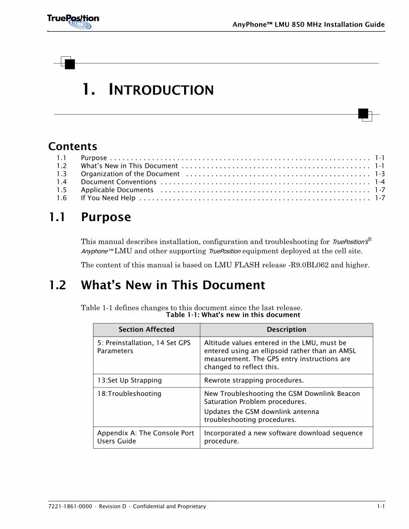
1.1 Purpose
This manual describes installation, configuration and troubleshooting for TruePosition’s®
Anyphone™ LMU and other supporting TruePosition equipment deployed at the cell site.
The content of this manual is based on LMU FLASH release -R9.0BL062 and higher.
1.2 What’s New in This Document
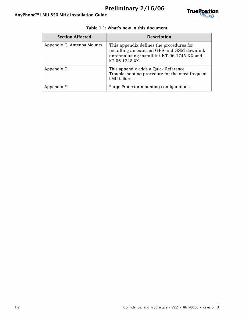
Table 1-1 defines changes to this document since the last release.Table 1-1: What’s new in this document
Section Affected Description
5: Preinstallation, 14 Set GPS Parameters
Altitude values entered in the LMU, must be entered using an ellipsoid rather than an AMSL measurement. The GPS entry instructions are changed to reflect this.
13:Set Up Strapping Rewrote strapping procedures.
18:Troubleshooting New Troubleshooting the GSM Downlink Beacon Saturation Problem procedures.
Updates the GSM downlink antenna troubleshooting procedures.
Appendix A: The Console Port Users Guide
Incorporated a new software download sequence procedure.
AnyPhone™ LMU 850 MHz Installation Guide
1-2 Confidential and Proprietary • 7221-1861-0000 • Revision D
Preliminary 2/16/06
Appendix C: Antenna Mounts This appendix defines the procedures for installing an external GPS and GSM downlink antenna using install kit KT-06-1745-XX and KT-06-1748-XX.
Appendix D: This appendix adds a Quick Reference Troubleshooting procedure for the most frequent LMU failures.
Appendix E: Surge Protector mounting configurations.
Table 1-1: What’s new in this document
Section Affected Description
AnyPhone™ LMU 850 MHz Installation Guide
7221-1861-0000 • Revision D • Confidential and Proprietary 1-3
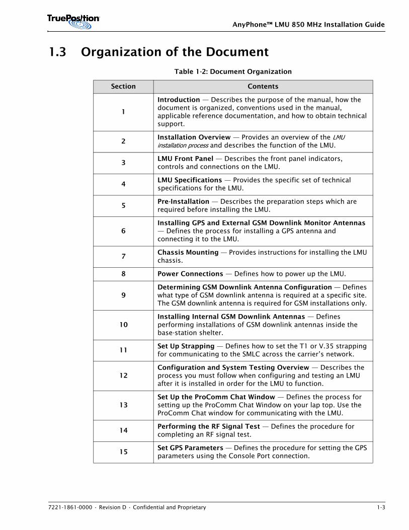
1.3 Organization of the Document
Table 1-2: Document Organization
Section Contents
1
Introduction — Describes the purpose of the manual, how the document is organized, conventions used in the manual, applicable reference documentation, and how to obtain technical support.
2Installation Overview — Provides an overview of the LMU installation process and describes the function of the LMU.
3LMU Front Panel — Describes the front panel indicators, controls and connections on the LMU.
4LMU Specifications — Provides the specific set of technical specifications for the LMU.
5Pre-Installation — Describes the preparation steps which are required before installing the LMU.
6Installing GPS and External GSM Downlink Monitor Antennas — Defines the process for installing a GPS antenna and connecting it to the LMU.
7Chassis Mounting — Provides instructions for installing the LMU chassis.
8 Power Connections — Defines how to power up the LMU.
9Determining GSM Downlink Antenna Configuration — Defines what type of GSM downlink antenna is required at a specific site. The GSM downlink antenna is required for GSM installations only.
10Installing Internal GSM Downlink Antennas — Defines performing installations of GSM downlink antennas inside the base-station shelter.
11Set Up Strapping — Defines how to set the T1 or V.35 strapping for communicating to the SMLC across the carrier’s network.
12Configuration and System Testing Overview — Describes the process you must follow when configuring and testing an LMU after it is installed in order for the LMU to function.
13Set Up the ProComm Chat Window — Defines the process for setting up the ProComm Chat Window on your lap top. Use the ProComm Chat window for communicating with the LMU.
14Performing the RF Signal Test — Defines the procedure for completing an RF signal test.
15Set GPS Parameters — Defines the procedure for setting the GPS parameters using the Console Port connection.
AnyPhone™ LMU 850 MHz Installation Guide
1-4 Confidential and Proprietary • 7221-1861-0000 • Revision D
Preliminary 2/16/06
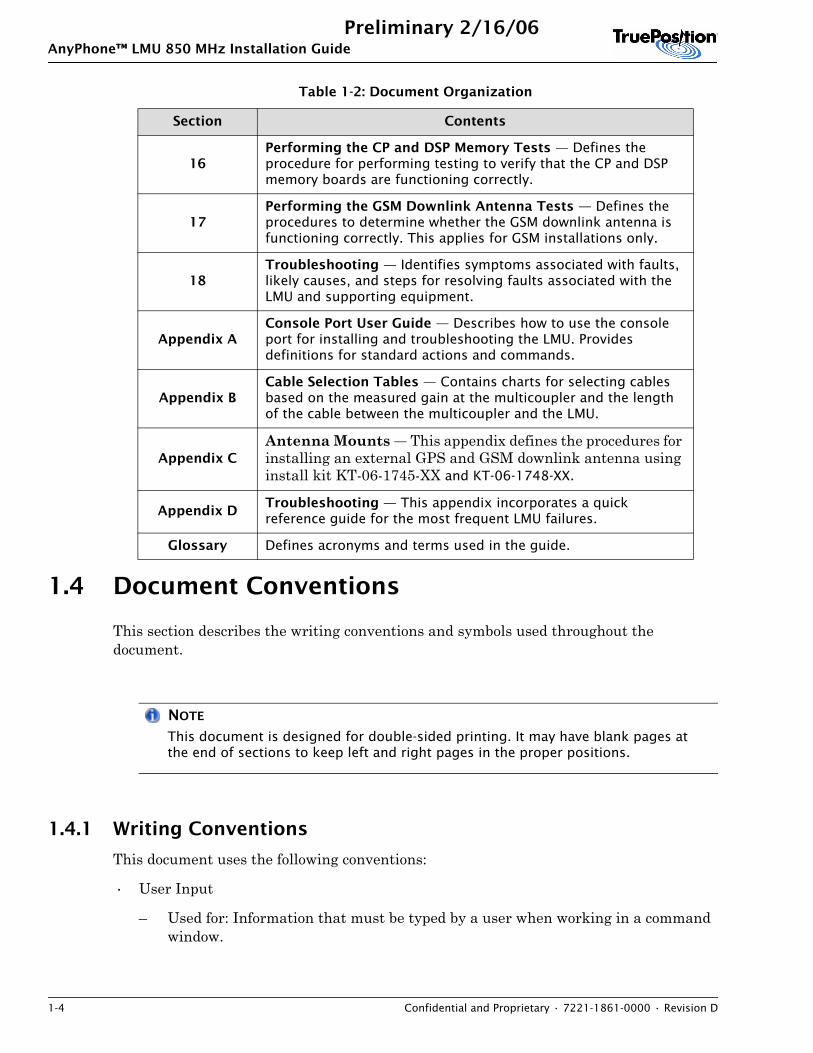
1.4 Document Conventions
This section describes the writing conventions and symbols used throughout the document.
NOTE
This document is designed for double-sided printing. It may have blank pages at the end of sections to keep left and right pages in the proper positions.
1.4.1 Writing Conventions
This document uses the following conventions:
• User Input
– Used for: Information that must be typed by a user when working in a command window.
16Performing the CP and DSP Memory Tests — Defines the procedure for performing testing to verify that the CP and DSP memory boards are functioning correctly.
17Performing the GSM Downlink Antenna Tests — Defines the procedures to determine whether the GSM downlink antenna is functioning correctly. This applies for GSM installations only.
18Troubleshooting — Identifies symptoms associated with faults, likely causes, and steps for resolving faults associated with the LMU and supporting equipment.
Appendix AConsole Port User Guide — Describes how to use the console port for installing and troubleshooting the LMU. Provides definitions for standard actions and commands.
Appendix BCable Selection Tables — Contains charts for selecting cables based on the measured gain at the multicoupler and the length of the cable between the multicoupler and the LMU.
Appendix CAntenna Mounts — This appendix defines the procedures for installing an external GPS and GSM downlink antenna using install kit KT-06-1745-XX and KT-06-1748-XX.
Appendix DTroubleshooting — This appendix incorporates a quick reference guide for the most frequent LMU failures.
Glossary Defines acronyms and terms used in the guide.
Table 1-2: Document Organization
Section Contents
AnyPhone™ LMU 850 MHz Installation Guide
7221-1861-0000 • Revision D • Confidential and Proprietary 1-5
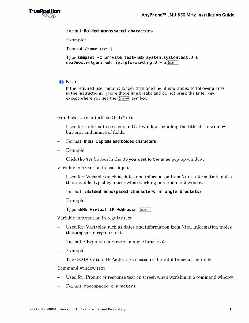
– Format: Bolded monospaced characters
– Examples:
Type cd /home R
Type snmpset -c private test-hub system.sysContact.0 s [email protected] ip.ipforwarding.0 = 2R
NOTE
If the required user input is longer than one line, it is wrapped to following lines in the instructions. Ignore those line breaks and do not press the Enter key, except where you see the R symbol.
• Graphical User Interface (GUI) Text
– Used for: Information seen in a GUI window including the title of the window, buttons, and names of fields.
– Format: Initial Capitals and bolded characters
– Example:
Click the Yes button in the Do you want to Continue pop-up window.
• Variable information in user input
– Used for: Variables such as dates and information from Vital Information tables that must be typed by a user when working in a command window.
– Format: <Bolded monospaced characters in angle brackets>
– Example:
Type <EMS Virtual IP Address> R
• Variable information in regular text
– Used for: Variables such as dates and information from Vital Information tables that appear in regular text.
– Format: <Regular characters in angle brackets>
– Example:
The <EMS Virtual IP Address> is listed in the Vital Information table.
• Command window text
– Used for: Prompt or response text on screen when working in a command window.
– Format: Monospaced characters
AnyPhone™ LMU 850 MHz Installation Guide
1-6 Confidential and Proprietary • 7221-1861-0000 • Revision D
Preliminary 2/16/06
– Examples:
Password:
Download Complete!
• Keycap images
– Used for: Keys on the computer keyboard that must be pressed by a user, usually while working in a command window.
– Format: Images of keys found on a normal keyboard.
– Examples:
R
C
S 4
1.4.2 Admonishments
Admonishments used in the documentation for this product have the following meanings:
!CAUTION
Indicates conditions that can cause problems if these steps are not done correctly. These problems may:•take significant extra time or effort to correct
•affect service
•cause delays in completing the overall procedure
WARNING
Indicates the presence of a hazard that must be avoided by following instructions carefully, because it can cause:
•death or severe personal injury
•significant service outages
•damage to equipment
•loss of critical data
AnyPhone™ LMU 850 MHz Installation Guide
7221-1861-0000 • Revision D • Confidential and Proprietary 1-7
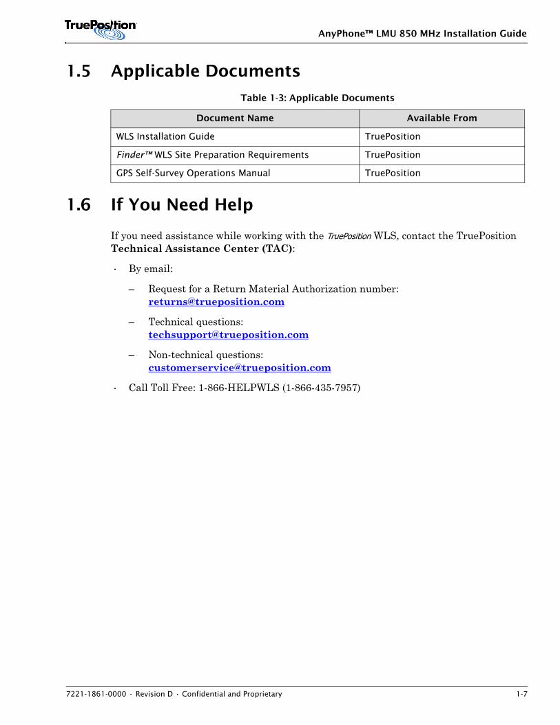
1.5 Applicable Documents
1.6 If You Need Help
If you need assistance while working with the TruePosition WLS, contact the TruePosition Technical Assistance Center (TAC):
• By email:
– Request for a Return Material Authorization number:[email protected]
– Technical questions: [email protected]
– Non-technical questions:[email protected]
• Call Toll Free: 1-866-HELPWLS (1-866-435-7957)
Table 1-3: Applicable Documents
Document Name Available From
WLS Installation Guide TruePosition
Finder™ WLS Site Preparation Requirements TruePosition
GPS Self-Survey Operations Manual TruePosition

AnyPhone™ LMU 850 MHz Installation Guide
1-8 Confidential and Proprietary • 7221-1861-0000 • Revision D
Preliminary 2/16/06
AnyPhone™ LMU 850 MHz Installation Guide
7221-1861-0000 • Revision D • Confidential and Proprietary 2-1
2. Finder WLS OVERVIEW
Contents2.1 Finder WLS Overview . . . . . . . . . . . . . . . . . . . . . . . . . . . . . . . . . . . . . . . . . . . . . . . . . . . . 2-12.2 LMU System Description . . . . . . . . . . . . . . . . . . . . . . . . . . . . . . . . . . . . . . . . . . . . . . . . . 2-5
2.1 Finder WLS Overview
The TruePosition Finder WLS is a network of managed nodes deployed in a carrier’s coverage area. It estimates the location of mobile devices in the area, based on the time difference of arrival (TDOA) of the signals from that mobile device in the WLS nodes surrounding them.
The WLS is implemented as an overlay network to a wireless carrier’s existing communications network. The system can estimate the geographic location, direction of travel, and speed of a Mobile Station (MS) or transmitter. The WLS was designed so that carriers can support location services for the substantial base of subscribers using a variety of air interface protocols. The WLS technology and product design supports numerous air interfaces.
TruePosition uses a patented form of TDOA with Pathfinder™ multipath mitigation as the core of its location technology. TDOA has been proven over many decades to be the location technology of choice for most high accuracy location applications for military and commercial purposes. The most popular location system in the world, the Global Positioning System (GPS), is also based on a form of TDOA.
The WLS architecture consists of the AnyPhone Location Measurement Unit (LMU) and iFind Serving Mobile Location Center (SMLC), which function together to perform the location calculations, and the ServiceGate Wireless Location Gateway (WLG) and Element Management System (EMS), which function together to support network management and user applications. The SCOUT application works with the EMS as a part of the Operations Support System (OSS). The SCOUT application provides the configuring mechanism for the WLS, while the EMS allows WLS operators to perform network management, limited system configuration management, performance management, and alarm management.
The WLS supports connectivity to external networks and can function as a service node, supporting Advanced Intelligent Network (AIN) triggers from external applications. The total system enables wireless carriers to develop, deploy, and manage new location services quickly and profitably.
AnyPhone™ LMU 850 MHz Installation Guide
2-2 Confidential and Proprietary • 7221-1861-0000 • Revision D
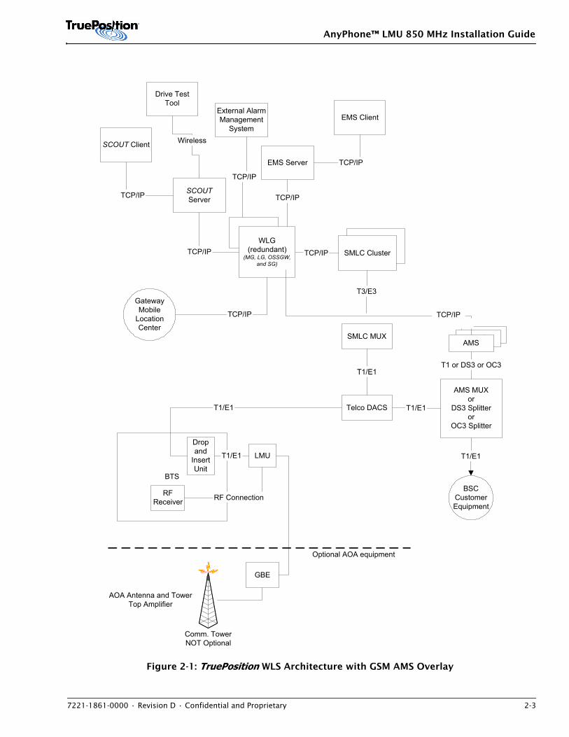
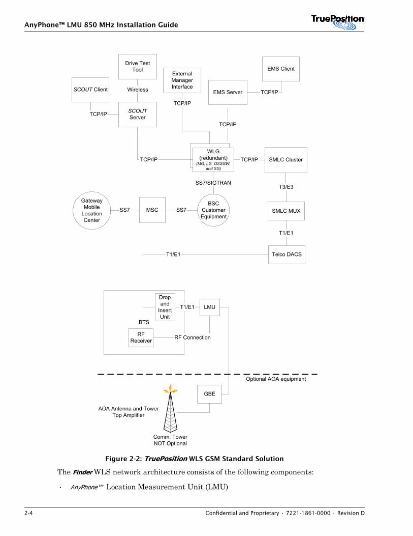
Typically, an AnyPhone LMU is collocated at carrier cell sites, while the remaining components are centrally located with the carrier's Mobile Switching Center (MSC). The interconnection between the LMU and the SMLC is a groomed digital signal (DS0, or fractional T1) link. The interconnection to the remaining components is based on the Internet protocol (IP), with the exception of the WLG-BSC interface, which is based on SS7 or SIGTRAN. Figure 2-1 and Figure 2-2 show the options for WLS configuration.
AnyPhone™ LMU 850 MHz Installation Guide
7221-1861-0000 • Revision D • Confidential and Proprietary 2-3
Figure 2-1: TruePosition WLS Architecture with GSM AMS Overlay
SMLC Cluster
SMLC MUX
Telco DACS
TCP/IP
AMS MUXor
DS3 Splitteror
OC3 Splitter
T3/E3
T1/E1T1 or DS3 or OC3
BTS
Dropand
InsertUnit
RFReceiver
LMU
T1/E1
RF Connection
T1/E1
GBE
Comm. TowerNOT Optional
AOA Antenna and TowerTop Amplifier
Optional AOA equipment
T1/E1
SCOUT Client
SCOUTServer
EMS Client
WLG(redundant)
(MG, LG, OSSGW,and SG)
TCP/IP
TCP/IP
TCP/IP
GatewayMobile
LocationCenter
EMS Server TCP/IP
TCP/IP
AMSAMSAMS
TCP/IP
BSCCustomerEquipment
T1/E1
External AlarmManagement
System
Drive TestTool
TCP/IP
Wireless
AnyPhone™ LMU 850 MHz Installation Guide
2-4 Confidential and Proprietary • 7221-1861-0000 • Revision D
Figure 2-2: TruePosition WLS GSM Standard Solution
The Finder WLS network architecture consists of the following components:
• AnyPhone™ Location Measurement Unit (LMU)
SMLC Cluster
SMLC MUX
Telco DACS
TCP/IP
T3/E3
T1/E1
BTS
Dropand
InsertUnit
RFReceiver
LMU
T1/E1
RF Connection
T1/E1
GBE
Comm. TowerNOT Optional
AOA Antenna and TowerTop Amplifier
Optional AOA equipment
SCOUT Client
SCOUTServer
EMS Client
WLG(redundant)
(MG, LG, OSSGW,and SG)
TCP/IP
TCP/IP
GatewayMobile
LocationCenter
EMS Server TCP/IP
TCP/IP
BSCCustomerEquipment
MSC
SS7/SIGTRAN
SS7 SS7
Drive TestTool
ExternalManagerInterface
TCP/IP
Wireless
AnyPhone™ LMU 850 MHz Installation Guide
7221-1861-0000 • Revision D • Confidential and Proprietary 2-5
• iFind™ Serving Mobile Location Center (SMLC)
• ServiceGate™ Wireless Location Gateway (WLG)
• Operations Support Systems (OSS) including an Element Management System (EMS) and the SCOUT™ application.
After an E911 call is made, the cell site Mobile Positioning Center (MPC) sends position requests to the WLG, which forwards them to the SMLC for processing. The LMU and SMLC operate together to calculate locations. The SMLC to WLG and WLG to MPC communicate using a TCP/IP LAN or WAN connection. The LMU is usually located at carrier cell sites. Other network components may be centrally located, or they may be located at the Mobile Telephone Switching Office (MTSO).
2.2 LMU System Description
NOTE
This section defines the overall function of the LMU (The remaining sections of the manual describe the installation of specific LMUs by band).
The TruePosition Anyphone Location Measurement Unit (LMU) is the front-end element of the TruePosition Finder WLS. The Anyphone LMU is fundamental in determining E911/112 location estimates. It can process signals from up to six separate antennas per cell site, using digital receiver modules. The LMU has the following features:
• It demodulates and digitizes radio frequency (RF) signals from multiple mobile wireless devices.
• It supports 850 and 1900 MHz, or dual-frequency band (e.g. 850/1900) operations with Global System for Mobile Communication (GSM), Timed Division Multiple Access (TDMA), and Advanced Mobile Phone System (AMPS) air-interface protocols.
• It has a one rack-unit (1RU) or two rack-unit (2RU) form factor platform that accommodates traditional omni or sectored antennas and radio diversity configurations.
• It contains a receiver assembly with six receiver channels. LMU receivers process wide-band RF energy from multiple directional antennas, typically configured as three sectors with diversity pairings, across each band of interest.
• In the dual-band configuration, it is equipped with a down converter module with six receiver channels that receive wide-band RF energy at the 1900 frequency bands. The down converter module translates these incoming frequency signals to the 850 frequency band.
From the receiver, signals are passed on to the Central Processor/Digital Signal Processor (CP/DSP) module for digitizing, digital storage and signal processing. The
AnyPhone™ LMU 850 MHz Installation Guide
2-6 Confidential and Proprietary • 7221-1861-0000 • Revision D
received signals in all cases must be time and frequency synchronized to support the location accuracy required from the TDOA system.
• By deploying LMU units across multiple cell sites, the network is protected from single point of failure scenarios, due to overlapping coverage of any given caller location from redundant cell sites.
AnyPhone ™ LMU 850 / 1900 MHz Dual Band Installation Guide
7221-1862-0000 • Revision D • Confidential and Proprietary 3-1
3. DUAL BAND LMU FRONT PANEL
Contents3.1 Introduction . . . . . . . . . . . . . . . . . . . . . . . . . . . . . . . . . . . . . . . . . . . . . . . . . . . . . . . . . . 3-13.2 Front Panel Description . . . . . . . . . . . . . . . . . . . . . . . . . . . . . . . . . . . . . . . . . . . . . . . . . . 3-1
3.1 Introduction
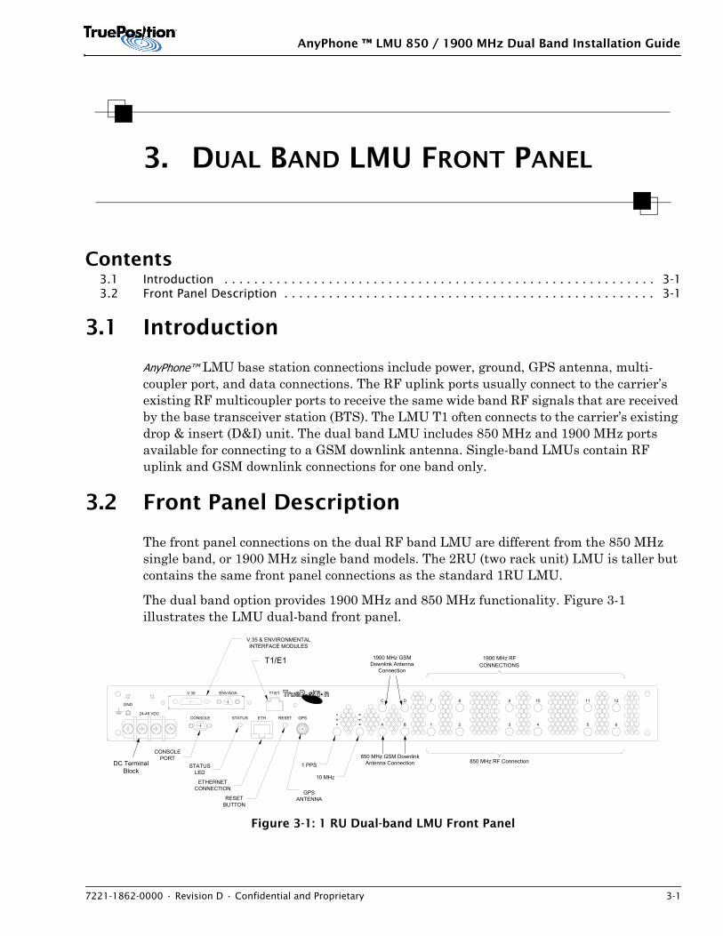
AnyPhone™ LMU base station connections include power, ground, GPS antenna, multi-coupler port, and data connections. The RF uplink ports usually connect to the carrier’s existing RF multicoupler ports to receive the same wide band RF signals that are received by the base transceiver station (BTS). The LMU T1 often connects to the carrier’s existing drop & insert (D&I) unit. The dual band LMU includes 850 MHz and 1900 MHz ports available for connecting to a GSM downlink antenna. Single-band LMUs contain RF uplink and GSM downlink connections for one band only.
3.2 Front Panel Description
The front panel connections on the dual RF band LMU are different from the 850 MHz single band, or 1900 MHz single band models. The 2RU (two rack unit) LMU is taller but contains the same front panel connections as the standard 1RU LMU.
The dual band option provides 1900 MHz and 850 MHz functionality. Figure 3-1 illustrates the LMU dual-band front panel.
Figure 3-1: 1 RU Dual-band LMU Front Panel
12111098D 7C
BA 21 3 54 6
STATUSLED
850 MHz RF Connection1 PPS
10 MHz
CONSOLEPORT
ETHERNETCONNECTION
V.35 & ENVIRONMENTALINTERFACE MODULES
1900 MHz RFCONNECTIONST1
GPSANTENNARESET
BUTTON
24-48 VDCCONSOLE STATUS RESETETH GPS
V.35
GND
ENV/AOA T1/E1
850 MHz GSM DownlinkAntenna Connection
1900 MHz GSMDownlink Antenna
Connection
DC TerminalBlock
T1/E1
AnyPhone ™ LMU 850 / 1900 MHz Dual Band Installation Guide
3-2 Confidential and Proprietary • 7221-1862-0000 • Revision D
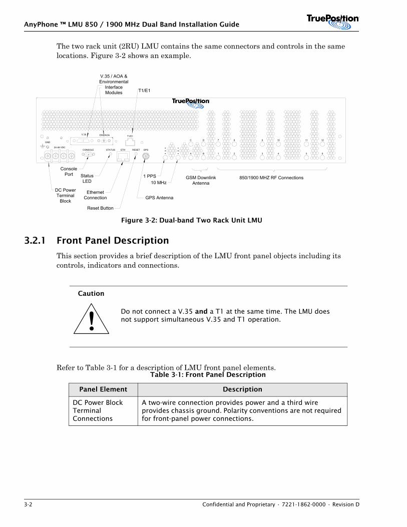
The two rack unit (2RU) LMU contains the same connectors and controls in the same locations. Figure 3-2 shows an example.
Figure 3-2: Dual-band Two Rack Unit LMU
3.2.1 Front Panel Description
This section provides a brief description of the LMU front panel objects including its controls, indicators and connections.
Refer to Table 3-1 for a description of LMU front panel elements.
Caution
Do not connect a V.35 and a T1 at the same time. The LMU does not support simultaneous V.35 and T1 operation.
Table 3-1: Front Panel Description
Panel Element Description
DC Power Block Terminal Connections
A two-wire connection provides power and a third wire provides chassis ground. Polarity conventions are not required for front-panel power connections.
12111098D 7C
BA 21 3 54 6
StatusLED
850/1900 MHZ RF Connections1 PPS10 MHz
ConsolePort
EthernetConnection
V.35 / AOA &Environmental
InterfaceModules T1/E1
GPS Antenna
Reset Button
24-48 VDCCONSOLE STATUS RESETETH GPS
V.35
GND
ENV/AOA T1/E1
DC PowerTerminal
Block
GSM DownlinkAntenna
!
AnyPhone ™ LMU 850 / 1900 MHz Dual Band Installation Guide
7221-1862-0000 • Revision D • Confidential and Proprietary 3-3
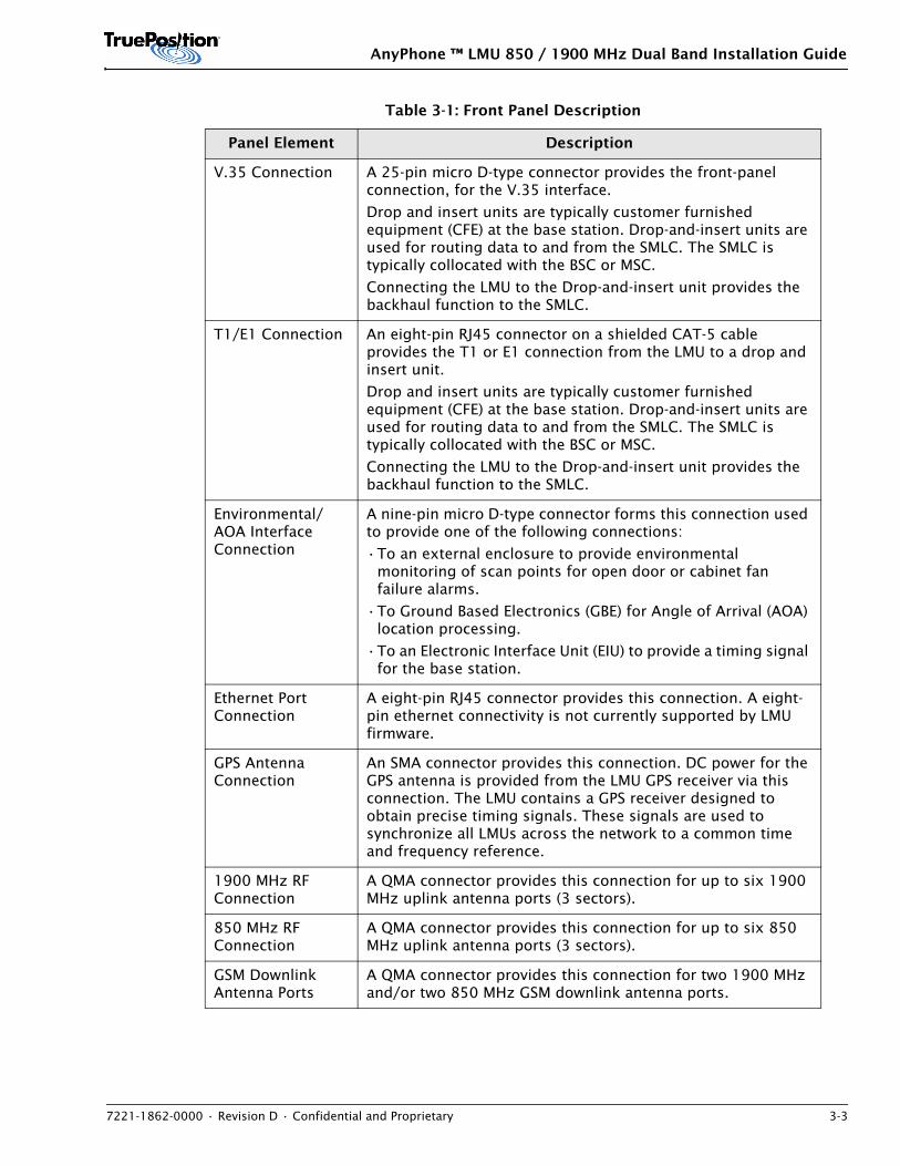
V.35 Connection A 25-pin micro D-type connector provides the front-panel connection, for the V.35 interface.
Drop and insert units are typically customer furnished equipment (CFE) at the base station. Drop-and-insert units are used for routing data to and from the SMLC. The SMLC is typically collocated with the BSC or MSC.
Connecting the LMU to the Drop-and-insert unit provides the backhaul function to the SMLC.
T1/E1 Connection An eight-pin RJ45 connector on a shielded CAT-5 cable provides the T1 or E1 connection from the LMU to a drop and insert unit.
Drop and insert units are typically customer furnished equipment (CFE) at the base station. Drop-and-insert units are used for routing data to and from the SMLC. The SMLC is typically collocated with the BSC or MSC.
Connecting the LMU to the Drop-and-insert unit provides the backhaul function to the SMLC.
Environmental/AOA Interface Connection
A nine-pin micro D-type connector forms this connection used to provide one of the following connections:
•To an external enclosure to provide environmental monitoring of scan points for open door or cabinet fan failure alarms.
•To Ground Based Electronics (GBE) for Angle of Arrival (AOA) location processing.
•To an Electronic Interface Unit (EIU) to provide a timing signal for the base station.
Ethernet Port Connection
A eight-pin RJ45 connector provides this connection. A eight-pin ethernet connectivity is not currently supported by LMU firmware.
GPS Antenna Connection
An SMA connector provides this connection. DC power for the GPS antenna is provided from the LMU GPS receiver via this connection. The LMU contains a GPS receiver designed to obtain precise timing signals. These signals are used to synchronize all LMUs across the network to a common time and frequency reference.
1900 MHz RF Connection
A QMA connector provides this connection for up to six 1900 MHz uplink antenna ports (3 sectors).
850 MHz RF Connection
A QMA connector provides this connection for up to six 850 MHz uplink antenna ports (3 sectors).
GSM Downlink Antenna Ports
A QMA connector provides this connection for two 1900 MHz and/or two 850 MHz GSM downlink antenna ports.
Table 3-1: Front Panel Description
Panel Element Description
AnyPhone ™ LMU 850 / 1900 MHz Dual Band Installation Guide
3-4 Confidential and Proprietary • 7221-1862-0000 • Revision D
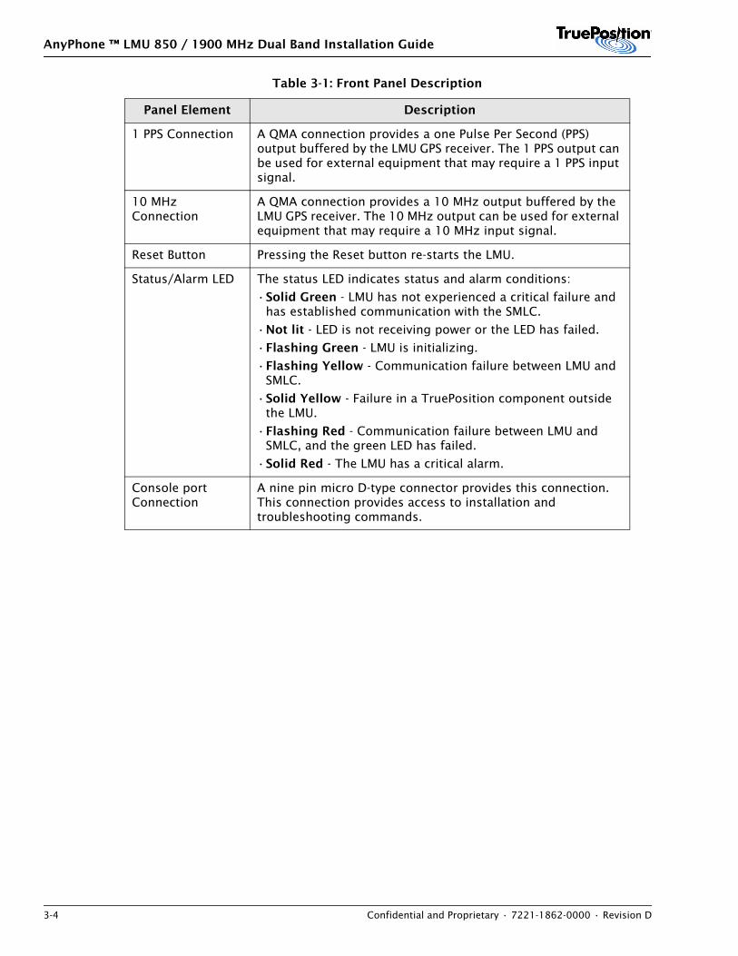
1 PPS Connection A QMA connection provides a one Pulse Per Second (PPS) output buffered by the LMU GPS receiver. The 1 PPS output can be used for external equipment that may require a 1 PPS input signal.
10 MHz Connection
A QMA connection provides a 10 MHz output buffered by the LMU GPS receiver. The 10 MHz output can be used for external equipment that may require a 10 MHz input signal.
Reset Button Pressing the Reset button re-starts the LMU.
Status/Alarm LED The status LED indicates status and alarm conditions:
•Solid Green - LMU has not experienced a critical failure and has established communication with the SMLC.
•Not lit - LED is not receiving power or the LED has failed.
•Flashing Green - LMU is initializing.
•Flashing Yellow - Communication failure between LMU and SMLC.
•Solid Yellow - Failure in a TruePosition component outside the LMU.
•Flashing Red - Communication failure between LMU and SMLC, and the green LED has failed.
•Solid Red - The LMU has a critical alarm.
Console port Connection
A nine pin micro D-type connector provides this connection. This connection provides access to installation and troubleshooting commands.
Table 3-1: Front Panel Description
Panel Element Description
AnyPhone ™ LMU 850 / 1900 MHz Dual Band Installation Guide
7221-1862-0000 • Revision D • Confidential and Proprietary 4-1
4. DUAL BAND LMU SPECIFICATIONS
Contents4.1 Introduction . . . . . . . . . . . . . . . . . . . . . . . . . . . . . . . . . . . . . . . . . . . . . . . . . . . . . . . . . . 4-14.2 Environmental . . . . . . . . . . . . . . . . . . . . . . . . . . . . . . . . . . . . . . . . . . . . . . . . . . . . . . . . . 4-14.3 Electrical . . . . . . . . . . . . . . . . . . . . . . . . . . . . . . . . . . . . . . . . . . . . . . . . . . . . . . . . . . . . . 4-24.4 Dimensions . . . . . . . . . . . . . . . . . . . . . . . . . . . . . . . . . . . . . . . . . . . . . . . . . . . . . . . . . . . 4-24.5 RF Input . . . . . . . . . . . . . . . . . . . . . . . . . . . . . . . . . . . . . . . . . . . . . . . . . . . . . . . . . . . . . 4-34.6 Radiated Emissions . . . . . . . . . . . . . . . . . . . . . . . . . . . . . . . . . . . . . . . . . . . . . . . . . . . . . 4-3
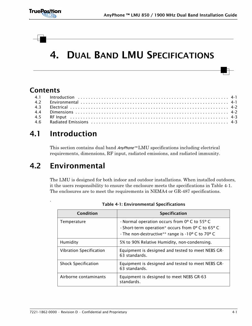
4.1 Introduction
This section contains dual band AnyPhone™ LMU specifications including electrical requirements, dimensions, RF input, radiated emissions, and radiated immunity.
4.2 Environmental
The LMU is designed for both indoor and outdoor installations. When installed outdoors, it the users responsibility to ensure the enclosure meets the specifications in Table 4-1. The enclosures are to meet the requirements in NEMA4 or GR-487 specifications.
.Table 4-1: Environmental Specifications
Condition Specification
Temperature •Normal operation occurs from 0º C to 55º C
•Short-term operation* occurs from 0º C to 65º C
•The non-destructive** range is -10º C to 70º C
Humidity 5% to 90% Relative Humidity, non-condensing.
Vibration Specification Equipment is designed and tested to meet NEBS GR-63 standards.
Shock Specification Equipment is designed and tested to meet NEBS GR-63 standards.
Airborne contaminants Equipment is designed to meet NEBS GR-63 standards.
AnyPhone ™ LMU 850 / 1900 MHz Dual Band Installation Guide
4-2 Confidential and Proprietary • 7221-1862-0000 • Revision D
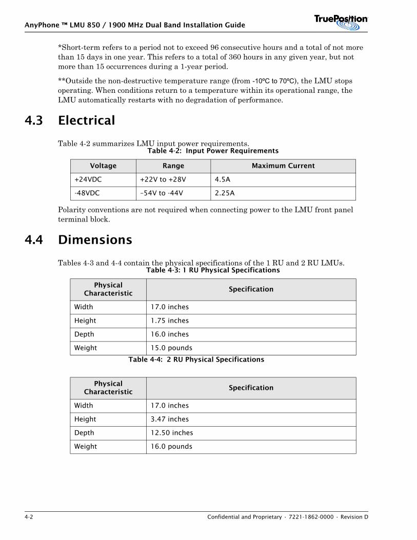
*Short-term refers to a period not to exceed 96 consecutive hours and a total of not more than 15 days in one year. This refers to a total of 360 hours in any given year, but not more than 15 occurrences during a 1-year period.
**Outside the non-destructive temperature range (from -10ºC to 70ºC), the LMU stops operating. When conditions return to a temperature within its operational range, the LMU automatically restarts with no degradation of performance.
4.3 Electrical
Table 4-2 summarizes LMU input power requirements.
Polarity conventions are not required when connecting power to the LMU front panel terminal block.
4.4 Dimensions
Tables 4-3 and 4-4 contain the physical specifications of the 1 RU and 2 RU LMUs.
Table 4-4: 2 RU Physical Specifications
Table 4-2: Input Power Requirements
Voltage Range Maximum Current
+24VDC +22V to +28V 4.5A
-48VDC –54V to -44V 2.25A
Table 4-3: 1 RU Physical Specifications
Physical Characteristic
Specification
Width 17.0 inches
Height 1.75 inches
Depth 16.0 inches
Weight 15.0 pounds
Physical Characteristic
Specification
Width 17.0 inches
Height 3.47 inches
Depth 12.50 inches
Weight 16.0 pounds
AnyPhone ™ LMU 850 / 1900 MHz Dual Band Installation Guide
7221-1862-0000 • Revision D • Confidential and Proprietary 4-3
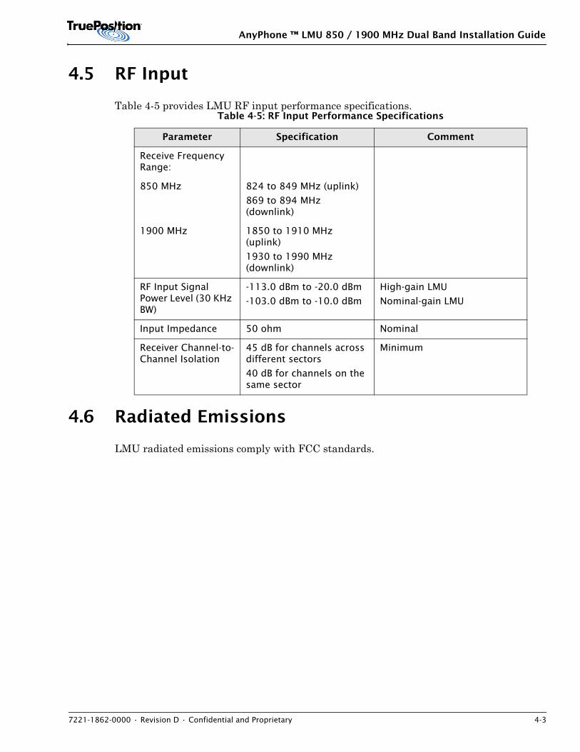
4.5 RF Input
Table 4-5 provides LMU RF input performance specifications.
4.6 Radiated Emissions
LMU radiated emissions comply with FCC standards.
Table 4-5: RF Input Performance Specifications
Parameter Specification Comment
Receive Frequency Range:
850 MHz 824 to 849 MHz (uplink)
869 to 894 MHz (downlink)
1900 MHz 1850 to 1910 MHz (uplink)
1930 to 1990 MHz (downlink)
RF Input Signal Power Level (30 KHz BW)
-113.0 dBm to -20.0 dBm
-103.0 dBm to -10.0 dBm
High-gain LMU
Nominal-gain LMU
Input Impedance 50 ohm Nominal
Receiver Channel-to-Channel Isolation
45 dB for channels across different sectors
40 dB for channels on the same sector
Minimum

AnyPhone ™ LMU 850 / 1900 MHz Dual Band Installation Guide
4-4 Confidential and Proprietary • 7221-1862-0000 • Revision D
AnyPhone ™ LMU 850 / 1900 MHz Dual Band Installation Guide
7221-1862-0000 • Revision D • Confidential and Proprietary 5-1
5. DUAL-BAND LMU PRE-INSTALLATION
Contents5.1 Overview . . . . . . . . . . . . . . . . . . . . . . . . . . . . . . . . . . . . . . . . . . . . . . . . . . . . . . . . . . . . . 5-15.2 Vital Information . . . . . . . . . . . . . . . . . . . . . . . . . . . . . . . . . . . . . . . . . . . . . . . . . . . . . . . 5-15.3 Constraints . . . . . . . . . . . . . . . . . . . . . . . . . . . . . . . . . . . . . . . . . . . . . . . . . . . . . . . . . . . 5-35.4 Select Cables . . . . . . . . . . . . . . . . . . . . . . . . . . . . . . . . . . . . . . . . . . . . . . . . . . . . . . . . . . 5-85.5 Equipment . . . . . . . . . . . . . . . . . . . . . . . . . . . . . . . . . . . . . . . . . . . . . . . . . . . . . . . . . . . 5-155.6 Final Pre-Installation Information . . . . . . . . . . . . . . . . . . . . . . . . . . . . . . . . . . . . . . . . . . 5-215.7 Measurements . . . . . . . . . . . . . . . . . . . . . . . . . . . . . . . . . . . . . . . . . . . . . . . . . . . . . . . . 5-23
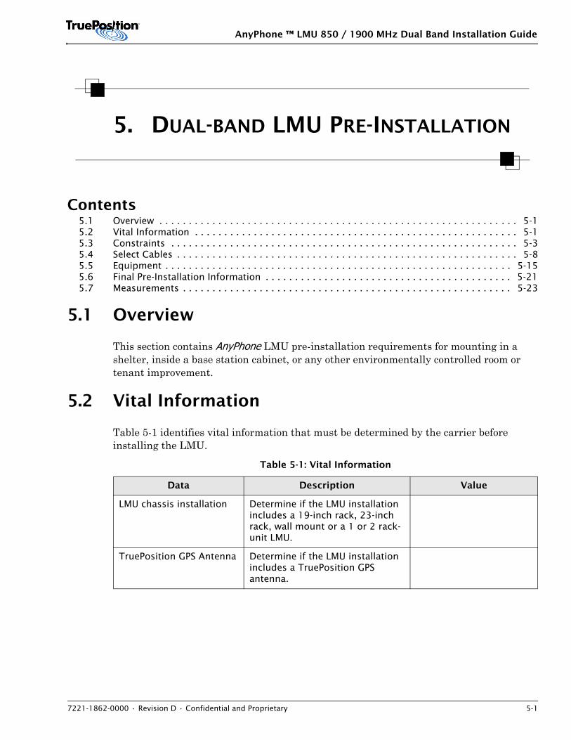
5.1 Overview
This section contains AnyPhone LMU pre-installation requirements for mounting in a shelter, inside a base station cabinet, or any other environmentally controlled room or tenant improvement.
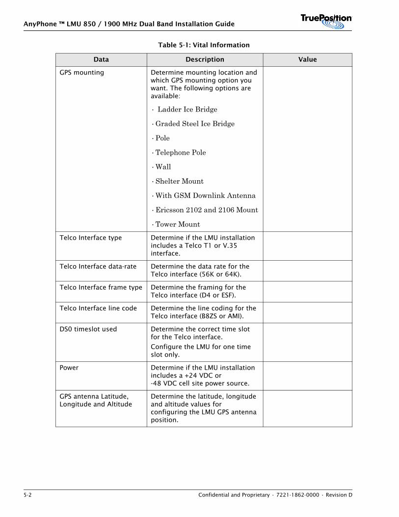
5.2 Vital Information
Table 5-1 identifies vital information that must be determined by the carrier before installing the LMU.
Table 5-1: Vital Information
Data Description Value
LMU chassis installation Determine if the LMU installation includes a 19-inch rack, 23-inch rack, wall mount or a 1 or 2 rack-unit LMU.
TruePosition GPS Antenna Determine if the LMU installation includes a TruePosition GPS antenna.
AnyPhone ™ LMU 850 / 1900 MHz Dual Band Installation Guide
5-2 Confidential and Proprietary • 7221-1862-0000 • Revision D
GPS mounting Determine mounting location and which GPS mounting option you want. The following options are available:
• Ladder Ice Bridge
•Graded Steel Ice Bridge
•Pole
•Telephone Pole
•Wall
•Shelter Mount
•With GSM Downlink Antenna
•Ericsson 2102 and 2106 Mount
•Tower Mount
Telco Interface type Determine if the LMU installation includes a Telco T1 or V.35 interface.
Telco Interface data-rate Determine the data rate for the Telco interface (56K or 64K).
Telco Interface frame type Determine the framing for the Telco interface (D4 or ESF).
Telco Interface line code Determine the line coding for the Telco interface (B8ZS or AMI).
DS0 timeslot used Determine the correct time slot for the Telco interface.
Configure the LMU for one time slot only.
Power Determine if the LMU installation includes a +24 VDC or-48 VDC cell site power source.
GPS antenna Latitude, Longitude and Altitude
Determine the latitude, longitude and altitude values for configuring the LMU GPS antenna position.
Table 5-1: Vital Information
Data Description Value
AnyPhone ™ LMU 850 / 1900 MHz Dual Band Installation Guide
7221-1862-0000 • Revision D • Confidential and Proprietary 5-3
5.3 Constraints
This section contains pre-installation constraints for mounting and cabling.
5.3.1 Mounting Constraints
This section contains constraints for bonding, grounding, and air gap clearances.
Bonding and Grounding
Install the LMU in a rack that has been grounded in accordance with GR-1089-CORE, Section 9.0 Bonding & Grounding.
Air Gap Clearances
LMU clearances for the front, right, and left side are maintained by the installer during the mounting process. Rear-panel air gap guards maintain the LMU rear clearance.
NOTE
Air-gap guards are installed on the LMU rear-panel during the factory assembly process. Do not remove the factory installed rear-panel air gap guards. These guards are provided to maintain the rear-panel clearance constraint. The Nortel 58000/512000 have a larger rear air gap of 95 to 120mm.
Table 5-2 defines the mounting constraints required to maintain proper air gap distances for the LMU:
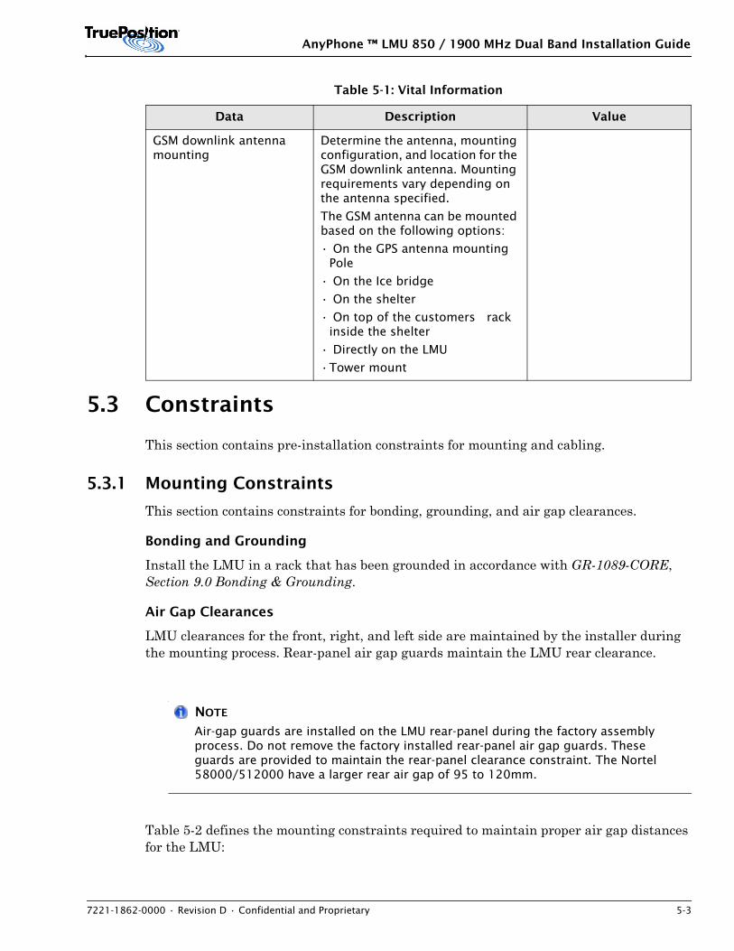
GSM downlink antenna mounting
Determine the antenna, mounting configuration, and location for the GSM downlink antenna. Mounting requirements vary depending on the antenna specified.
The GSM antenna can be mounted based on the following options:
• On the GPS antenna mounting Pole
• On the Ice bridge
• On the shelter
• On top of the customers rack inside the shelter
• Directly on the LMU
•Tower mount
Table 5-1: Vital Information
Data Description Value
AnyPhone ™ LMU 850 / 1900 MHz Dual Band Installation Guide
5-4 Confidential and Proprietary • 7221-1862-0000 • Revision D
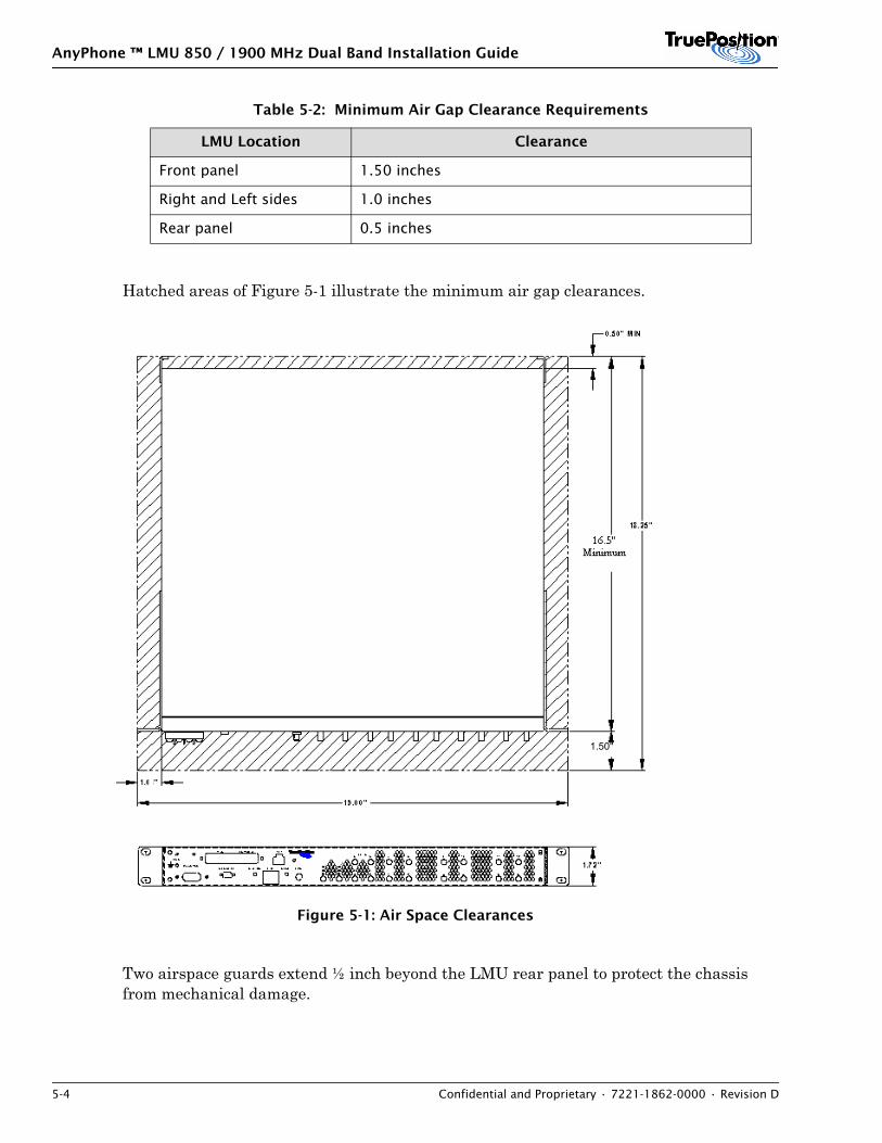
Hatched areas of Figure 5-1 illustrate the minimum air gap clearances.
Figure 5-1: Air Space Clearances
Two airspace guards extend ½ inch beyond the LMU rear panel to protect the chassis from mechanical damage.
Table 5-2: Minimum Air Gap Clearance Requirements
LMU Location Clearance
Front panel 1.50 inches
Right and Left sides 1.0 inches
Rear panel 0.5 inches
1.50"

AnyPhone ™ LMU 850 / 1900 MHz Dual Band Installation Guide
7221-1862-0000 • Revision D • Confidential and Proprietary 5-5
Table 5-2 defines the mounting constraints required to maintain proper air gap distances for the 2 rack unit LMU.
Figure 5-2: 2 Rack Unit LMU
5.3.2 Cable Bend Radius
Do not bend RF, GPS, GSM downlink, power, and ground cables tighter than the radius specified in Table 5-3
NOTE
The RG8X cable type refers to Huber Suhner RFC 12464, Huber Suhner RFC 240T, Belden 7808R or Andrews CNT240.
AnyPhone ™ LMU 850 / 1900 MHz Dual Band Installation Guide
5-6 Confidential and Proprietary • 7221-1862-0000 • Revision D
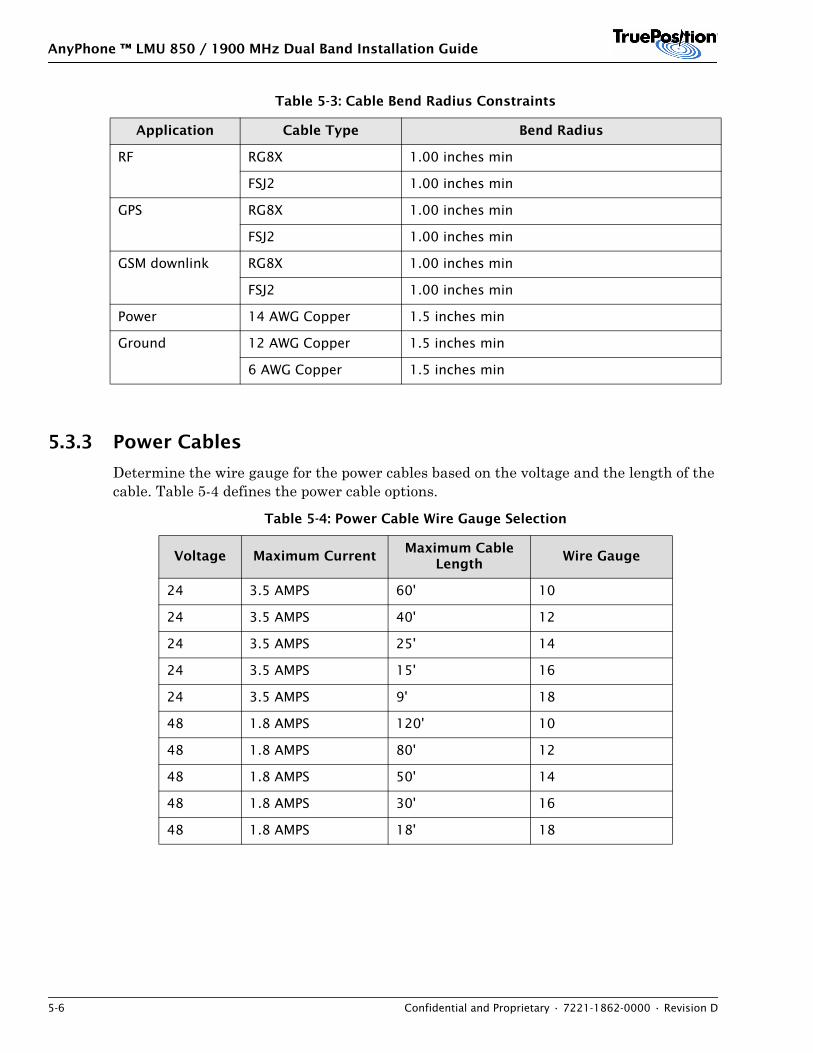
5.3.3 Power Cables
Determine the wire gauge for the power cables based on the voltage and the length of the cable. Table 5-4 defines the power cable options.
Table 5-3: Cable Bend Radius Constraints
Application Cable Type Bend Radius
RF RG8X 1.00 inches min
FSJ2 1.00 inches min
GPS RG8X 1.00 inches min
FSJ2 1.00 inches min
GSM downlink RG8X 1.00 inches min
FSJ2 1.00 inches min
Power 14 AWG Copper 1.5 inches min
Ground 12 AWG Copper 1.5 inches min
6 AWG Copper 1.5 inches min
Table 5-4: Power Cable Wire Gauge Selection
Voltage Maximum CurrentMaximum Cable
LengthWire Gauge
24 3.5 AMPS 60' 10
24 3.5 AMPS 40' 12
24 3.5 AMPS 25' 14
24 3.5 AMPS 15' 16
24 3.5 AMPS 9' 18
48 1.8 AMPS 120' 10
48 1.8 AMPS 80' 12
48 1.8 AMPS 50' 14
48 1.8 AMPS 30' 16
48 1.8 AMPS 18' 18

AnyPhone ™ LMU 850 / 1900 MHz Dual Band Installation Guide
7221-1862-0000 • Revision D • Confidential and Proprietary 5-7
NOTE
Hardware such as cables and connectors can vary from cell site to cell site. These variations depend on existing cell site equipment as well as cell site geographical layout.
5.3.4 Ground Cables
Ground cables must be 12 AWG copper wire. The ground wire must be as short as possible. Ground strap should be a few inches and tied off to the rack.
5.3.5 Multicoupler Gain
For optimal operation the RF multicoupler should provide 6 to 32 dB of gain.
Channel Boundaries
The LMU supports the 850 MHz and 1900 MHz frequency spectrum with constraints on RF tests performed on channels 157 through 1831. These constraints are intended for the BIT 6 procedure described in Section 15: Dual Band RF Signal Test.
Tests on narrow band LMUs should not be performed between the channel boundaries described in this section.
Table 5-5 identifies tuning boundaries that cannot be crossed when defining a BIT 6 test for LMUs with narrow band receivers.
Table 5-5: LMU Channel Boundaries
Frequency Channel Boundaries
850 MHz 157 through 158
333 through 334
507 through 508
655 through 656
1900 MHz 160 through 161
330 through 331
500 through 501
660 through 661
830 through 831
1000 through 1001
1160 through 1161
1330 through 1331
1500 through 1501
1660 through 1661
1830 through 1831
AnyPhone ™ LMU 850 / 1900 MHz Dual Band Installation Guide
5-8 Confidential and Proprietary • 7221-1862-0000 • Revision D
NOTE
Do not specify channel ranges that cross LMU channel boundaries. The LMU does not process RF signals when channel boundaries are crossed.
LMUs with wide band receivers do not have channel boundary constraints*.
*The following LMUs have a wide band receiver:
• Model 063200/063300 — Domestic
• Model 0933200/093300 — Domestic
• Model 066300 — International
• Model 096300 — International
5.3.6 GPS ParametersThe following constraints are necessary for GPS parameter entries.
The tolerance for the altitude value is within 1 meter. The tolerance for the latitude and longitude is +/-.00002 degrees or +/- 2e-5 degrees. (7.2 feet)
5.4 Select Cables
This section describes considerations for selecting RF, GPS, GSM downlink, T1, and V.35 cables.
5.4.1 RF Cables
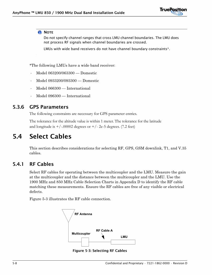
Select RF cables for operating between the multicoupler and the LMU. Measure the gain at the multicoupler and the distance between the multicoupler and the LMU. Use the 1900 MHz and 850 MHz Cable Selection Charts in Appendix D to identify the RF cable matching these measurements. Ensure the RF cables are free of any visible or electrical defects.
Figure 5-3 illustrates the RF cable connection.
Figure 5-3: Selecting RF Cables
RF Antenna
MulticouplerLMU
RF Cable A
AnyPhone ™ LMU 850 / 1900 MHz Dual Band Installation Guide
7221-1862-0000 • Revision D • Confidential and Proprietary 5-9
NOTE
Multicoupler can contain RF filters, amplifiers, and splitters in any combination.
1 To select the RF cable (A):
2 Measure the length of RF cable (A) between the multicoupler and the LMU. Record this length measurement _________m.
3 Measure the multicoupler gain using the appropriate test equipment. Record the gain measurement. ________dB.
4 Refer to the 850 MHz or 1900 MHz RF Cable Selection Charts in Appendix D.
5 Use the Cable Selection Charts to select the cable type matching the cable distance measured in step 2 and the RF antenna gain measured in step 3.
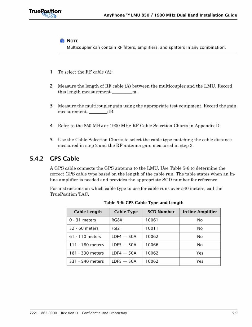
5.4.2 GPS Cable
A GPS cable connects the GPS antenna to the LMU. Use Table 5-6 to determine the correct GPS cable type based on the length of the cable run. The table states when an in-line amplifier is needed and provides the appropriate SCD number for reference.
For instructions on which cable type to use for cable runs over 540 meters, call the TruePosition TAC.
Table 5-6: GPS Cable Type and Length
Cable Length Cable Type SCD Number In-line Amplifier
0 - 31 meters RG8X 10061 No
32 - 60 meters FSJ2 10011 No
61 - 110 meters LDF4 — 50A 10062 No
111 - 180 meters LDF5 — 50A 10066 No
181 - 330 meters LDF4 — 50A 10062 Yes
331 - 540 meters LDF5 — 50A 10062 Yes
AnyPhone ™ LMU 850 / 1900 MHz Dual Band Installation Guide
5-10 Confidential and Proprietary • 7221-1862-0000 • Revision D
NOTE
The RG8X cable type refers to Huber Suhner RFC 12464, Huber Suhner RFC 240T, Belden 7808R, or Andrew CNT240.
AnyPhone ™ LMU 850 / 1900 MHz Dual Band Installation Guide
7221-1862-0000 • Revision D • Confidential and Proprietary 5-11
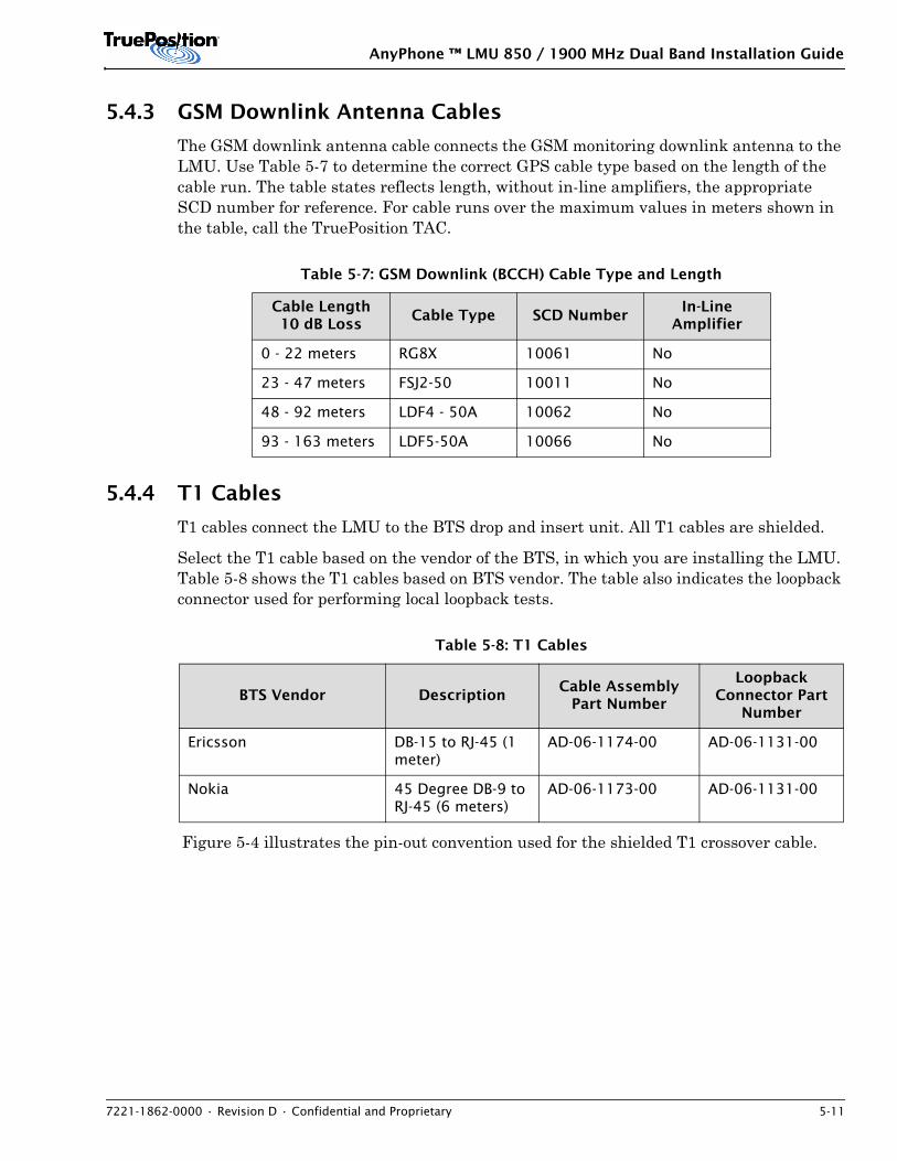
5.4.3 GSM Downlink Antenna Cables
The GSM downlink antenna cable connects the GSM monitoring downlink antenna to the LMU. Use Table 5-7 to determine the correct GPS cable type based on the length of the cable run. The table states reflects length, without in-line amplifiers, the appropriate SCD number for reference. For cable runs over the maximum values in meters shown in the table, call the TruePosition TAC.
5.4.4 T1 Cables
T1 cables connect the LMU to the BTS drop and insert unit. All T1 cables are shielded.
Select the T1 cable based on the vendor of the BTS, in which you are installing the LMU. Table 5-8 shows the T1 cables based on BTS vendor. The table also indicates the loopback connector used for performing local loopback tests.
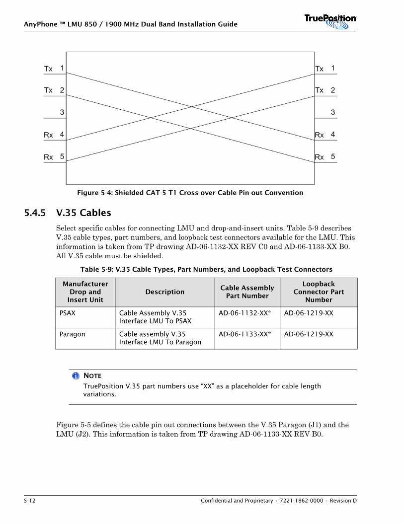
Figure 5-4 illustrates the pin-out convention used for the shielded T1 crossover cable.
Table 5-7: GSM Downlink (BCCH) Cable Type and Length
Cable Length10 dB Loss
Cable Type SCD NumberIn-Line
Amplifier
0 - 22 meters RG8X 10061 No
23 - 47 meters FSJ2-50 10011 No
48 - 92 meters LDF4 - 50A 10062 No
93 - 163 meters LDF5-50A 10066 No
Table 5-8: T1 Cables
BTS Vendor DescriptionCable Assembly
Part Number
Loopback Connector Part
Number
Ericsson DB-15 to RJ-45 (1 meter)
AD-06-1174-00 AD-06-1131-00
Nokia 45 Degree DB-9 to RJ-45 (6 meters)
AD-06-1173-00 AD-06-1131-00
AnyPhone ™ LMU 850 / 1900 MHz Dual Band Installation Guide
5-12 Confidential and Proprietary • 7221-1862-0000 • Revision D
Figure 5-4: Shielded CAT-5 T1 Cross-over Cable Pin-out Convention
5.4.5 V.35 Cables
Select specific cables for connecting LMU and drop-and-insert units. Table 5-9 describes V.35 cable types, part numbers, and loopback test connectors available for the LMU. This information is taken from TP drawing AD-06-1132-XX REV C0 and AD-06-1133-XX B0. All V.35 cable must be shielded.
NOTE
TruePosition V.35 part numbers use “XX” as a placeholder for cable length variations.
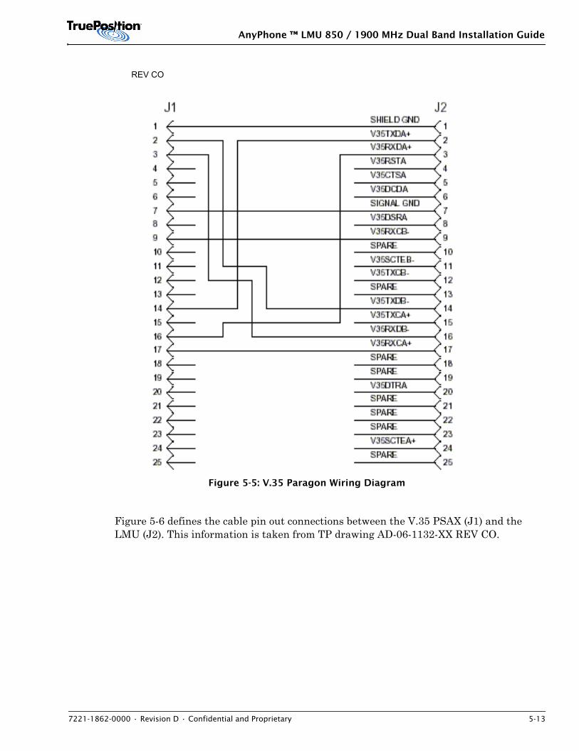
Figure 5-5 defines the cable pin out connections between the V.35 Paragon (J1) and the LMU (J2). This information is taken from TP drawing AD-06-1133-XX REV B0.
Table 5-9: V.35 Cable Types, Part Numbers, and Loopback Test Connectors
Manufacturer Drop and
Insert UnitDescription
Cable Assembly Part Number
Loopback Connector Part
Number
PSAX Cable Assembly V.35 Interface LMU To PSAX
AD-06-1132-XX* AD-06-1219-XX
Paragon Cable assembly V.35 Interface LMU To Paragon
AD-06-1133-XX* AD-06-1219-XX
AnyPhone ™ LMU 850 / 1900 MHz Dual Band Installation Guide
7221-1862-0000 • Revision D • Confidential and Proprietary 5-13
Figure 5-5: V.35 Paragon Wiring Diagram
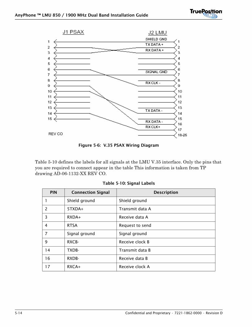
Figure 5-6 defines the cable pin out connections between the V.35 PSAX (J1) and the LMU (J2). This information is taken from TP drawing AD-06-1132-XX REV CO.
REV CO
AnyPhone ™ LMU 850 / 1900 MHz Dual Band Installation Guide
5-14 Confidential and Proprietary • 7221-1862-0000 • Revision D
Figure 5-6: V.35 PSAX Wiring Diagram
Table 5-10 defines the labels for all signals at the LMU V.35 interface. Only the pins that you are required to connect appear in the table This information is taken from TP drawing AD-06-1132-XX REV CO.
Table 5-10: Signal Labels
PIN Connection Signal Description
1 Shield ground Shield ground
2 5TXDA+ Transmit data A
3 RXDA+ Receive data A
4 RTSA Request to send
7 Signal ground Signal ground
9 RXCB- Receive clock B
14 TXDB- Transmit data B
16 RXDB- Receive data B
17 RXCA+ Receive clock A
REV CO
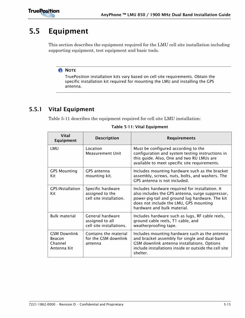
AnyPhone ™ LMU 850 / 1900 MHz Dual Band Installation Guide
7221-1862-0000 • Revision D • Confidential and Proprietary 5-15
5.5 Equipment
This section describes the equipment required for the LMU cell site installation including supporting equipment, test equipment and basic tools.
NOTE
TruePosition installation kits vary based on cell site requirements. Obtain the specific installation kit required for mounting the LMU and installing the GPS antenna.
5.5.1 Vital Equipment
Table 5-11 describes the equipment required for cell site LMU installation:
Table 5-11: Vital Equipment
Vital Equipment
Description Requirements
LMU Location Measurement Unit
Must be configured according to the configuration and system testing instructions in this guide. Also, One and two RU LMUs are available to meet specific site requirements.
GPS Mounting Kit
GPS antenna mounting kit.
Includes mounting hardware such as the bracket assembly, screws, nuts, bolts, and washers. The GPS antenna is not included.
GPS iNstallation Kit
Specific hardware assigned to the cell site installation.
Includes hardware required for installation. It also includes the GPS antenna, surge suppressor, power-pig-tail and ground lug hardware. The kit does not include the LMU, GPS mounting hardware and bulk material.
Bulk material General hardware assigned to all cell site installations.
Includes hardware such as lugs, RF cable reels, ground cable reels, T1 cable, and weatherproofing tape.
GSM Downlink Beacon Channel Antenna Kit
Contains the material for the GSM downlink antenna
Includes mounting hardware such as the antenna and bracket assembly for single and dual-band GSM downlink antenna installations. Options include installations inside or outside the cell site shelter.
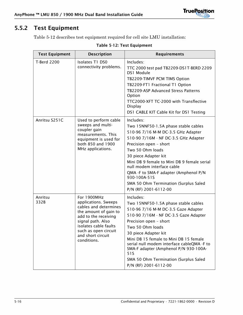
AnyPhone ™ LMU 850 / 1900 MHz Dual Band Installation Guide
5-16 Confidential and Proprietary • 7221-1862-0000 • Revision D
5.5.2 Test Equipment
Table 5-12 describes test equipment required for cell site LMU installation:
Table 5-12: Test Equipment
Test Equipment Description Requirements
T-Berd 2200 Isolates T1 DS0 connectivity problems.
Includes:
TTC 2000 test pad TB2209-DS1T-BERD 2209 DS1 Module
TB2209-TIMVF PCM TIMS Option
TB2209-FT1 Fractional T1 Option
TB2209-ASP Advanced Stress Patterns Option
TTC2000-XFT TC-2000 with Transflective Display
DS1 CABLE KIT Cable Kit for DS1 Testing
Anritsu S251C Used to perform cable sweeps and multi-coupler gain measurements. This equipment is used for both 850 and 1900 MHz applications.
Includes:
Two 15NNF50-1.5A phase stable cables
510-96 7/16 M-M DC-3.5 GHz Adapter
510-90 7/16M - NF DC-3.5 GHz Adapter
Precision open – short
Two 50 Ohm loads
30 piece Adapter kit
Mini DB 9 female to Mini DB 9 female serial null modem interface cable
QMA -F to SMA-F adapter (Amphenol P/N 930-100A-51S
SMA 50 Ohm Termination (Surplus Saled
P/N (RF) 2001-6112-00
Anritsu332B
For 1900MHz applications. Sweeps cables and determines the amount of gain to add to the receiving signal path. Also isolates cable faults such as open circuit and short circuit conditions.
Includes:
Two 15NNF50-1.5A phase stable cables
510-96 7/16 M-M DC-3.5 Gaze Adapter
510-90 7/16M - NF DC-3.5 Gaze Adapter
Precision open – short
Two 50 Ohm loads
30 piece Adapter kit
Mini DB 15 female to Mini DB 15 female serial null modem interface cableQMA -F to SMA-F adapter (Amphenol P/N 930-100A-51S
SMA 50 Ohm Termination (Surplus Saled
P/N (RF) 2001-6112-00
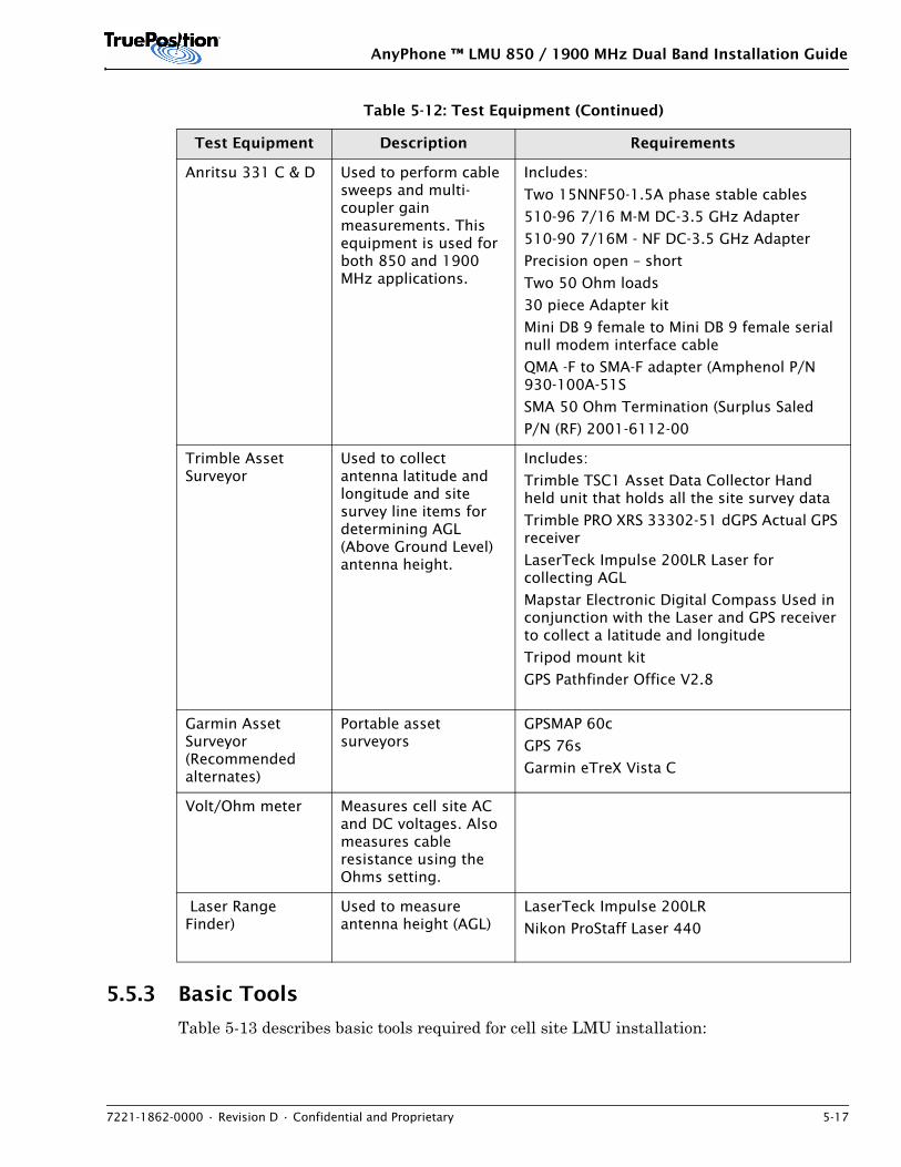
AnyPhone ™ LMU 850 / 1900 MHz Dual Band Installation Guide
7221-1862-0000 • Revision D • Confidential and Proprietary 5-17
5.5.3 Basic Tools
Table 5-13 describes basic tools required for cell site LMU installation:
Anritsu 331 C & D Used to perform cable sweeps and multi-coupler gain measurements. This equipment is used for both 850 and 1900 MHz applications.
Includes:
Two 15NNF50-1.5A phase stable cables
510-96 7/16 M-M DC-3.5 GHz Adapter
510-90 7/16M - NF DC-3.5 GHz Adapter
Precision open – short
Two 50 Ohm loads
30 piece Adapter kit
Mini DB 9 female to Mini DB 9 female serial null modem interface cable
QMA -F to SMA-F adapter (Amphenol P/N 930-100A-51S
SMA 50 Ohm Termination (Surplus Saled
P/N (RF) 2001-6112-00
Trimble Asset Surveyor
Used to collect antenna latitude and longitude and site survey line items for determining AGL (Above Ground Level) antenna height.
Includes:
Trimble TSC1 Asset Data Collector Hand held unit that holds all the site survey data
Trimble PRO XRS 33302-51 dGPS Actual GPS receiver
LaserTeck Impulse 200LR Laser for collecting AGL
Mapstar Electronic Digital Compass Used in conjunction with the Laser and GPS receiver to collect a latitude and longitude
Tripod mount kit
GPS Pathfinder Office V2.8
Garmin Asset Surveyor (Recommended alternates)
Portable asset surveyors
GPSMAP 60c
GPS 76s
Garmin eTreX Vista C
Volt/Ohm meter Measures cell site AC and DC voltages. Also measures cable resistance using the Ohms setting.
Laser Range Finder)
Used to measure antenna height (AGL)
LaserTeck Impulse 200LR
Nikon ProStaff Laser 440
Table 5-12: Test Equipment (Continued)
Test Equipment Description Requirements
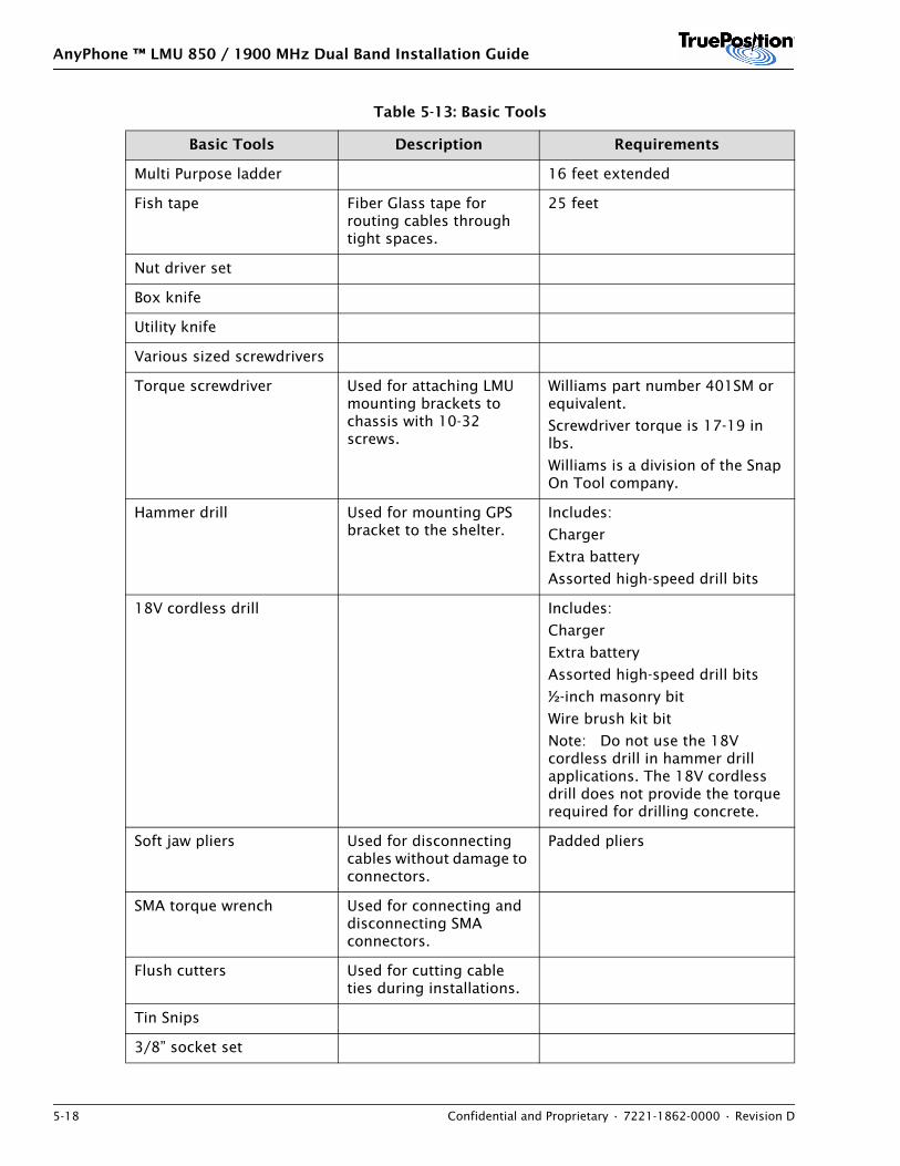
AnyPhone ™ LMU 850 / 1900 MHz Dual Band Installation Guide
5-18 Confidential and Proprietary • 7221-1862-0000 • Revision D
Table 5-13: Basic Tools
Basic Tools Description Requirements
Multi Purpose ladder 16 feet extended
Fish tape Fiber Glass tape for routing cables through tight spaces.
25 feet
Nut driver set
Box knife
Utility knife
Various sized screwdrivers
Torque screwdriver Used for attaching LMU mounting brackets to chassis with 10-32 screws.
Williams part number 401SM or equivalent.
Screwdriver torque is 17-19 in lbs.
Williams is a division of the Snap On Tool company.
Hammer drill Used for mounting GPS bracket to the shelter.
Includes:
Charger
Extra battery
Assorted high-speed drill bits
18V cordless drill Includes:
Charger
Extra battery
Assorted high-speed drill bits
½-inch masonry bit
Wire brush kit bit
Note: Do not use the 18V cordless drill in hammer drill applications. The 18V cordless drill does not provide the torque required for drilling concrete.
Soft jaw pliers Used for disconnecting cables without damage to connectors.
Padded pliers
SMA torque wrench Used for connecting and disconnecting SMA connectors.
Flush cutters Used for cutting cable ties during installations.
Tin Snips
3/8” socket set
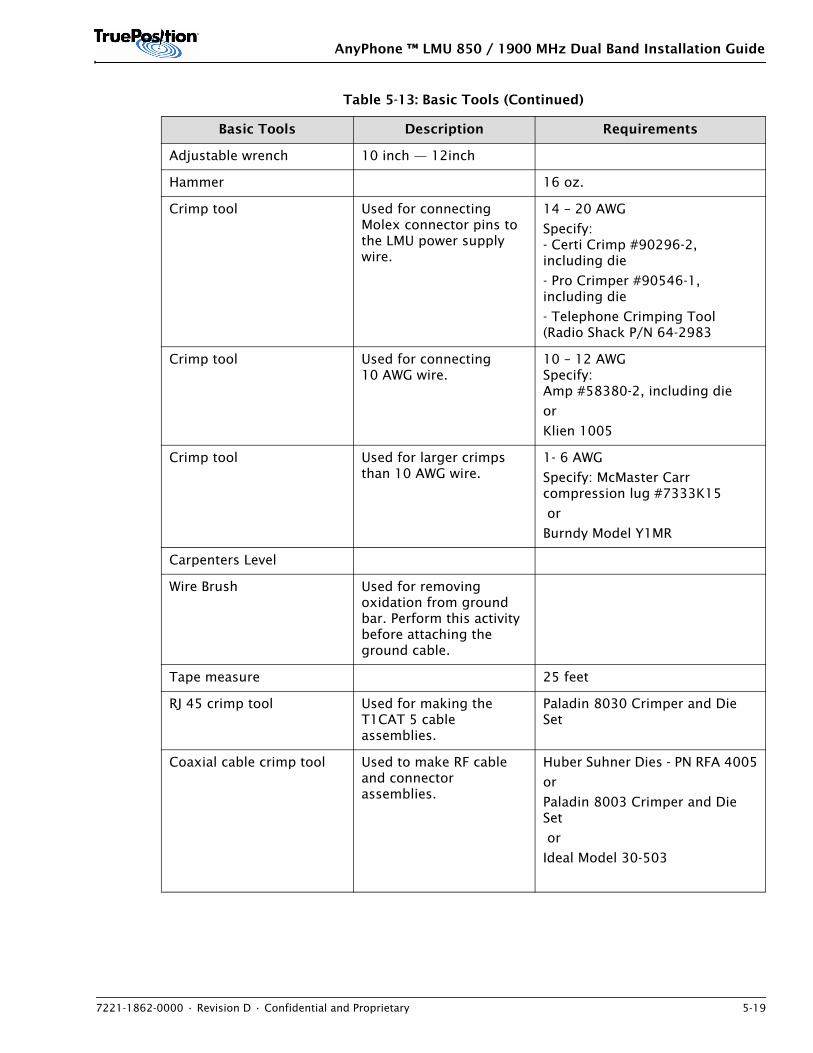
AnyPhone ™ LMU 850 / 1900 MHz Dual Band Installation Guide
7221-1862-0000 • Revision D • Confidential and Proprietary 5-19
Adjustable wrench 10 inch — 12inch
Hammer 16 oz.
Crimp tool Used for connecting Molex connector pins to the LMU power supply wire.
14 – 20 AWG
Specify:- Certi Crimp #90296-2, including die
- Pro Crimper #90546-1, including die
- Telephone Crimping Tool (Radio Shack P/N 64-2983
Crimp tool Used for connecting 10 AWG wire.
10 – 12 AWG Specify:Amp #58380-2, including die
or
Klien 1005
Crimp tool Used for larger crimps than 10 AWG wire.
1- 6 AWG
Specify: McMaster Carr compression lug #7333K15
or
Burndy Model Y1MR
Carpenters Level
Wire Brush Used for removing oxidation from ground bar. Perform this activity before attaching the ground cable.
Tape measure 25 feet
RJ 45 crimp tool Used for making the T1CAT 5 cable assemblies.
Paladin 8030 Crimper and Die Set
Coaxial cable crimp tool Used to make RF cable and connector assemblies.
Huber Suhner Dies - PN RFA 4005
or
Paladin 8003 Crimper and Die Set
or
Ideal Model 30-503
Table 5-13: Basic Tools (Continued)
Basic Tools Description Requirements
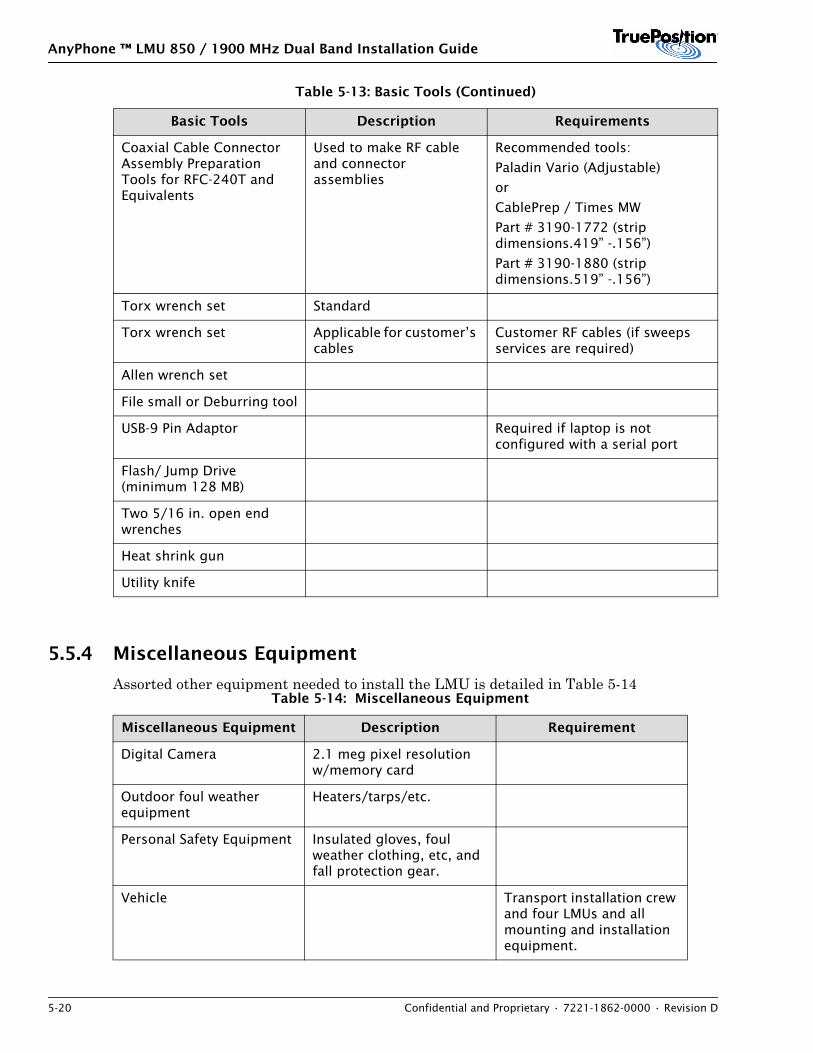
AnyPhone ™ LMU 850 / 1900 MHz Dual Band Installation Guide
5-20 Confidential and Proprietary • 7221-1862-0000 • Revision D
5.5.4 Miscellaneous Equipment
Assorted other equipment needed to install the LMU is detailed in Table 5-14
Coaxial Cable Connector Assembly Preparation Tools for RFC-240T and Equivalents
Used to make RF cable and connector assemblies
Recommended tools:
Paladin Vario (Adjustable)
or
CablePrep / Times MW
Part # 3190-1772 (strip dimensions.419” -.156”)
Part # 3190-1880 (strip dimensions.519” -.156”)
Torx wrench set Standard
Torx wrench set Applicable for customer’s cables
Customer RF cables (if sweeps services are required)
Allen wrench set
File small or Deburring tool
USB-9 Pin Adaptor Required if laptop is not configured with a serial port
Flash/ Jump Drive (minimum 128 MB)
Two 5/16 in. open end wrenches
Heat shrink gun
Utility knife
Table 5-14: Miscellaneous Equipment
Miscellaneous Equipment Description Requirement
Digital Camera 2.1 meg pixel resolution w/memory card
Outdoor foul weather equipment
Heaters/tarps/etc.
Personal Safety Equipment Insulated gloves, foul weather clothing, etc, and fall protection gear.
Vehicle Transport installation crew and four LMUs and all mounting and installation equipment.
Table 5-13: Basic Tools (Continued)
Basic Tools Description Requirements
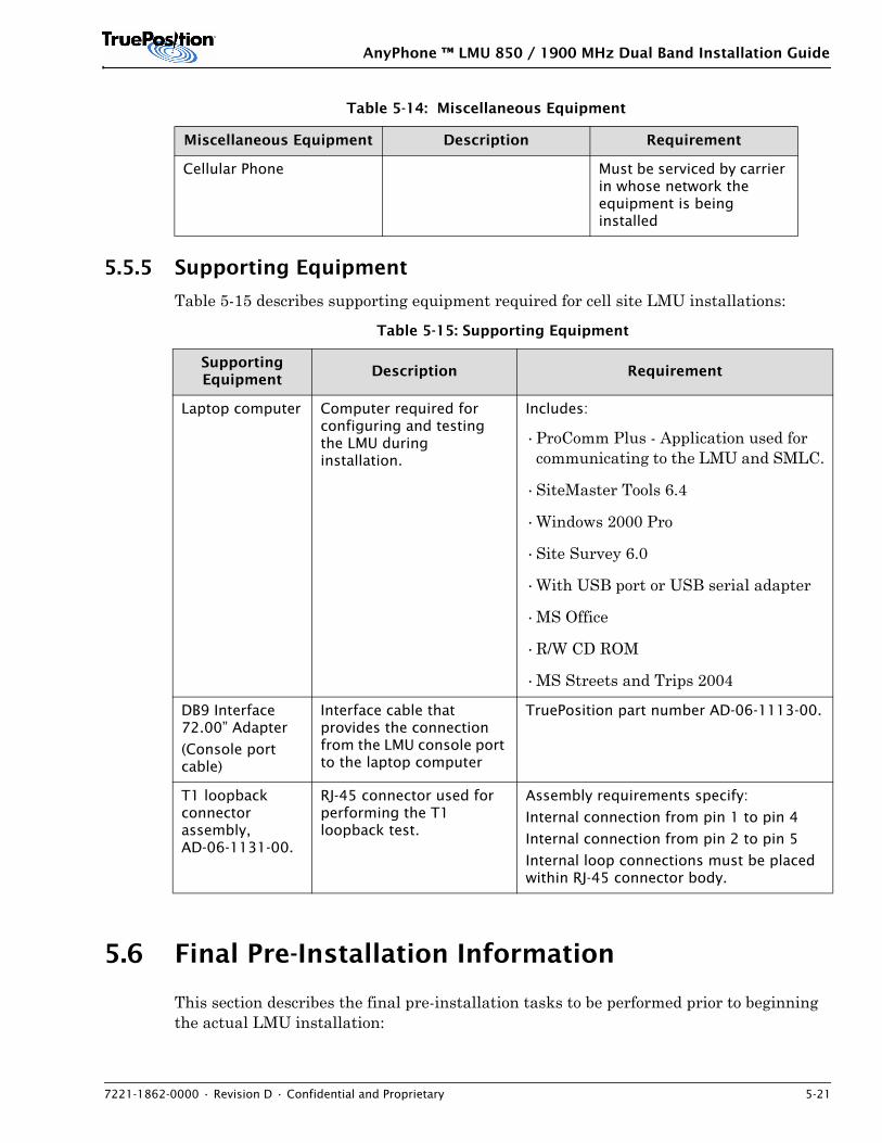
AnyPhone ™ LMU 850 / 1900 MHz Dual Band Installation Guide
7221-1862-0000 • Revision D • Confidential and Proprietary 5-21
5.5.5 Supporting Equipment
Table 5-15 describes supporting equipment required for cell site LMU installations:
5.6 Final Pre-Installation Information
This section describes the final pre-installation tasks to be performed prior to beginning the actual LMU installation:
Cellular Phone Must be serviced by carrier in whose network the equipment is being installed
Table 5-15: Supporting Equipment
Supporting Equipment
Description Requirement
Laptop computer Computer required for configuring and testing the LMU during installation.
Includes:
•ProComm Plus - Application used for communicating to the LMU and SMLC.
•SiteMaster Tools 6.4
•Windows 2000 Pro
•Site Survey 6.0
•With USB port or USB serial adapter
•MS Office
•R/W CD ROM
•MS Streets and Trips 2004
DB9 Interface 72.00” Adapter
(Console port cable)
Interface cable that provides the connection from the LMU console port to the laptop computer
TruePosition part number AD-06-1113-00.
T1 loopback connector assembly, AD-06-1131-00.
RJ-45 connector used for performing the T1 loopback test.
Assembly requirements specify:
Internal connection from pin 1 to pin 4
Internal connection from pin 2 to pin 5
Internal loop connections must be placed within RJ-45 connector body.
Table 5-14: Miscellaneous Equipment
Miscellaneous Equipment Description Requirement
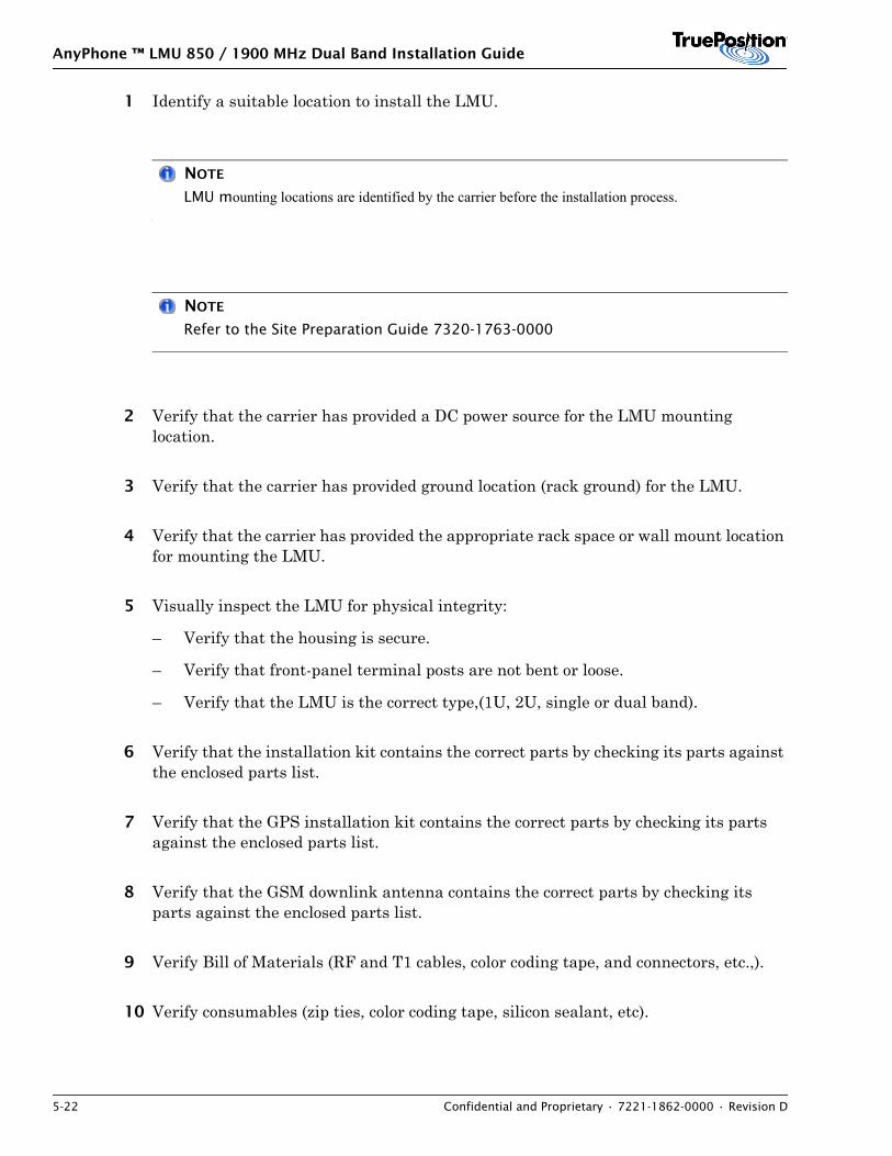
AnyPhone ™ LMU 850 / 1900 MHz Dual Band Installation Guide
5-22 Confidential and Proprietary • 7221-1862-0000 • Revision D
1 Identify a suitable location to install the LMU.
NOTE
LMU mounting locations are identified by the carrier before the installation process.
NOTE
Refer to the Site Preparation Guide 7320-1763-0000
2 Verify that the carrier has provided a DC power source for the LMU mounting location.
3 Verify that the carrier has provided ground location (rack ground) for the LMU.
4 Verify that the carrier has provided the appropriate rack space or wall mount location for mounting the LMU.
5 Visually inspect the LMU for physical integrity:
– Verify that the housing is secure.
– Verify that front-panel terminal posts are not bent or loose.
– Verify that the LMU is the correct type,(1U, 2U, single or dual band).
6 Verify that the installation kit contains the correct parts by checking its parts against the enclosed parts list.
7 Verify that the GPS installation kit contains the correct parts by checking its parts against the enclosed parts list.
8 Verify that the GSM downlink antenna contains the correct parts by checking its parts against the enclosed parts list.
9 Verify Bill of Materials (RF and T1 cables, color coding tape, and connectors, etc.,).
10 Verify consumables (zip ties, color coding tape, silicon sealant, etc).
AnyPhone ™ LMU 850 / 1900 MHz Dual Band Installation Guide
7221-1862-0000 • Revision D • Confidential and Proprietary 5-23
11 Verify the availability of free multi coupler ports, or directional couplers.
12 Verify adequate space on ground bar for GPS and downlink antenna.
13 Verify correct cable routing.
14 Verify adequate location for the GPS antenna location base, in accordance with GPS Antenna Location Basic rule Set.
5.7 Measurements
Gather any other information specified by your site survey instructions.
NOTE
Site survey instructions are not included in this document.

AnyPhone ™ LMU 850 / 1900 MHz Dual Band Installation Guide
5-24 Confidential and Proprietary • 7221-1862-0000 • Revision D
AnyPhone™ LMU 850 MHz Installation Guide
7221-1861-0000 • Revision D • Confidential and Proprietary 6-1
6. DETERMINING THE GSM DOWNLINK ANTENNA CONFIGURATION
GSM downlink antenna installation applies for GSM installations only. To support GSM location processing from an AnyPhone LMU, you must install a GSM downlink antenna at the cell site, connect it to the LMU, and download GSM capable software.
GSM downlink antennas can be installed either inside the base-station shelter or outside with or separate from the GPS antenna, typically attached to the shelter, or on the ice bridge.
Determine the GSM downlink antenna configuration based on the following criteria:
• If some cell sites in a particular market do not have LMUs (less than 100% deployment), install an external model downlink antenna in the same location as the GPS antenna. If it is not possible to mount the GSM downlink antenna with the GPS antenna, mount it on the ice bridge or on the shelter. For instructions, see the appropriate Installing External GSM Downlink Antenna section.
• If LMUs are being installed at all cell sites in a market (100% deployment), install an internal (inside the shelter) model GSM downlink antenna based on the following rule, if recommended by network design.
– Install the press-on internal GSM downlink antenna if space allows; otherwise, install the internal downlink antenna on the equipment rack. If space does not allow the rack mounting option, install a magnetically mounted antenna. For instructions, see the appropriate Internal GSM Downlink Antennas section.
NOTE
Before mounting the GSM downlink antenna to the ice bridge, ensure that this is an approved mounting method at the cell site.

AnyPhone™ LMU 850 MHz Installation Guide
6-2 Confidential and Proprietary • 7221-1861-0000 • Revision D
AnyPhone™ LMU 850 MHz Installation Guide
7221-1861-0000 • Revision D • Confidential and Proprietary 7-1
7. INSTALL GPS AND EXTERNAL GSM DOWNLINK MONITOR ANTENNAS
Contents7.1 Overview . . . . . . . . . . . . . . . . . . . . . . . . . . . . . . . . . . . . . . . . . . . . . . . . . . . . . . . . . . . . . 7-17.2 Mounting Requirements . . . . . . . . . . . . . . . . . . . . . . . . . . . . . . . . . . . . . . . . . . . . . . . . . 7-37.3 GPS Antenna Only Mounting Options . . . . . . . . . . . . . . . . . . . . . . . . . . . . . . . . . . . . . . . . 7-47.4 GPS with GSM Downlink Antenna Mounting Options . . . . . . . . . . . . . . . . . . . . . . . . . . . 7-117.5 GPS Antenna Mount on an Ericsson BTS Cabinet RBS . . . . . . . . . . . . . . . . . . . . . . . . . . . 7-187.6 GPS Antenna Cable Connections . . . . . . . . . . . . . . . . . . . . . . . . . . . . . . . . . . . . . . . . . . 7-217.7 External GSM Downlink Antenna Cable Connections . . . . . . . . . . . . . . . . . . . . . . . . . . . 7-347.8 Connecting to an Existing GPS Antenna . . . . . . . . . . . . . . . . . . . . . . . . . . . . . . . . . . . . . 7-39
7.1 Overview
When installing an LMU, a GPS antenna with lightning protection must be installed at the BTS. This section defines how to install a GPS antenna and connect it.
This document applies only if you are installing antennas at a cell site using the following installation kits:
• KT-06-1728-XX
• KT-06-1729-XX
• KT-06-1730-XX
NOTE
If the installation requires KT-06-1745-XX, see Appendix C: Antenna Mounts.
The carrier determines if a new GPS antenna must be installed or if an existing GPS antenna can be connected. If the site layout requires using an existing GPS antenna, install necessary equipment as defined in section 7.8: Connecting to an Existing GPS Antenna.
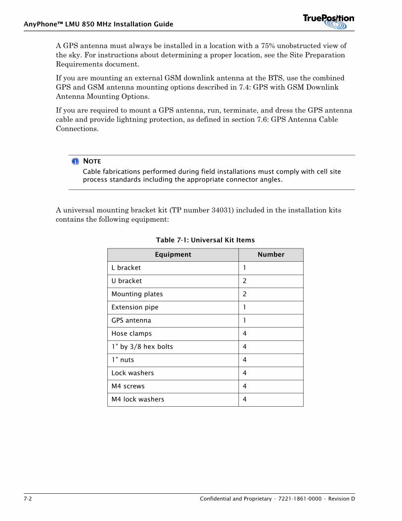
AnyPhone™ LMU 850 MHz Installation Guide
7-2 Confidential and Proprietary • 7221-1861-0000 • Revision D
A GPS antenna must always be installed in a location with a 75% unobstructed view of the sky. For instructions about determining a proper location, see the Site Preparation Requirements document.
If you are mounting an external GSM downlink antenna at the BTS, use the combined GPS and GSM antenna mounting options described in 7.4: GPS with GSM Downlink Antenna Mounting Options.
If you are required to mount a GPS antenna, run, terminate, and dress the GPS antenna cable and provide lightning protection, as defined in section 7.6: GPS Antenna Cable Connections.
NOTE
Cable fabrications performed during field installations must comply with cell site process standards including the appropriate connector angles.
A universal mounting bracket kit (TP number 34031) included in the installation kits contains the following equipment:
Table 7-1: Universal Kit Items
Equipment Number
L bracket 1
U bracket 2
Mounting plates 2
Extension pipe 1
GPS antenna 1
Hose clamps 4
1” by 3/8 hex bolts 4
1” nuts 4
Lock washers 4
M4 screws 4
M4 lock washers 4
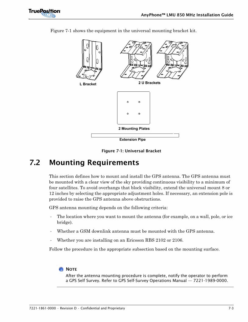
AnyPhone™ LMU 850 MHz Installation Guide
7221-1861-0000 • Revision D • Confidential and Proprietary 7-3
Figure 7-1 shows the equipment in the universal mounting bracket kit.
Figure 7-1: Universal Bracket
7.2 Mounting Requirements
This section defines how to mount and install the GPS antenna. The GPS antenna must be mounted with a clear view of the sky providing continuous visibility to a minimum of four satellites. To avoid overhangs that block visibility, extend the universal mount 8 or 12 inches by selecting the appropriate adjustment holes. If necessary, an extension pole is provided to raise the GPS antenna above obstructions.
GPS antenna mounting depends on the following criteria:
• The location where you want to mount the antenna (for example, on a wall, pole, or ice bridge).
• Whether a GSM downlink antenna must be mounted with the GPS antenna.
• Whether you are installing on an Ericsson RBS 2102 or 2106.
Follow the procedure in the appropriate subsection based on the mounting surface.
NOTE
After the antenna mounting procedure is complete, notify the operator to perform a GPS Self Survey. Refer to GPS Self-Survey Operations Manual — 7221-1989-0000.
L Bracket 2 U Brackets
2 Mounting Plates
Extension Pipe
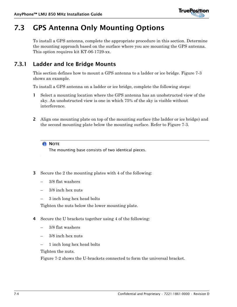
AnyPhone™ LMU 850 MHz Installation Guide
7-4 Confidential and Proprietary • 7221-1861-0000 • Revision D
7.3 GPS Antenna Only Mounting Options
To install a GPS antenna, complete the appropriate procedure in this section. Determine the mounting approach based on the surface where you are mounting the GPS antenna. This option requires kit KT-06-1729-xx.
7.3.1 Ladder and Ice Bridge Mounts
This section defines how to mount a GPS antenna to a ladder or ice bridge. Figure 7-3 shows an example.
To install a GPS antenna on a ladder or ice bridge, complete the following steps:
1 Select a mounting location where the GPS antenna has an unobstructed view of the sky. An unobstructed view is one in which 75% of the sky is visible without interference.
2 Align one mounting plate on top of the mounting surface (the ladder or ice bridge) and the second mounting plate below the mounting surface. Refer to Figure 7-3.
NOTE
The mounting base consists of two identical pieces.
3 Secure the 2 the mounting plates with 4 of the following:
– 3/8 flat washers
– 3/8 inch hex nuts
– 3 inch long hex head bolts Tighten the nuts below the lower mounting plate.
4 Secure the U brackets together using 4 of the following:
– 3/8 flat washers
– 3/8 inch hex nuts
– 1 inch long hex head bolts Tighten the nuts.Figure 7-2 shows the U-brackets connected to form the universal bracket.
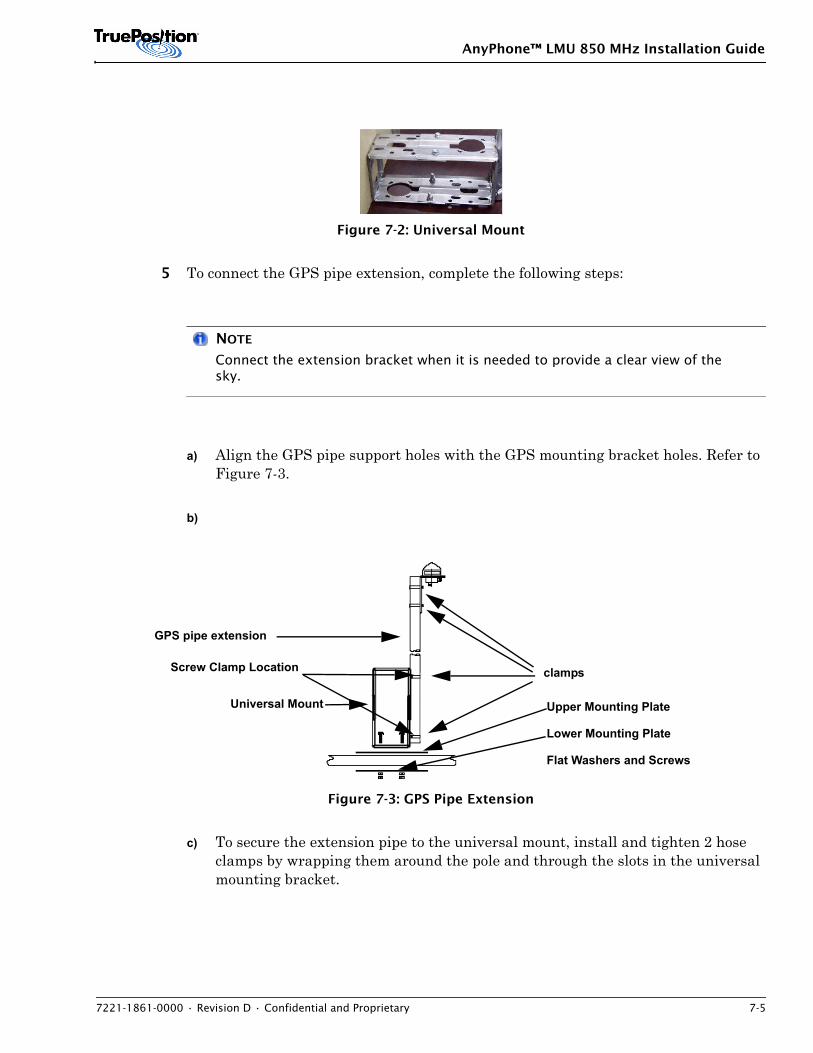
AnyPhone™ LMU 850 MHz Installation Guide
7221-1861-0000 • Revision D • Confidential and Proprietary 7-5
Figure 7-2: Universal Mount
5 To connect the GPS pipe extension, complete the following steps:
NOTE
Connect the extension bracket when it is needed to provide a clear view of the sky.
a) Align the GPS pipe support holes with the GPS mounting bracket holes. Refer to Figure 7-3.
b)
Figure 7-3: GPS Pipe Extension
c) To secure the extension pipe to the universal mount, install and tighten 2 hose clamps by wrapping them around the pole and through the slots in the universal mounting bracket.
GPS pipe extension
clamps
Universal Mount Upper Mounting Plate
Lower Mounting Plate
Flat Washers and Screws
Screw Clamp Location
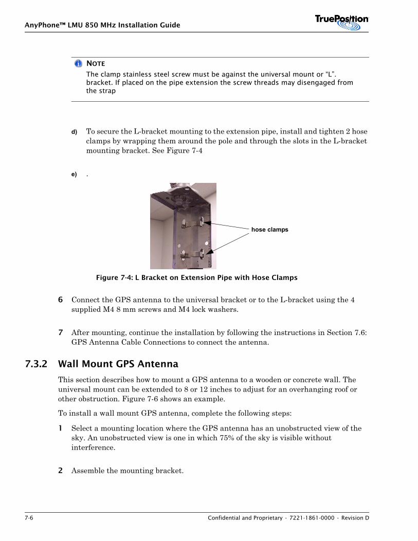
AnyPhone™ LMU 850 MHz Installation Guide
7-6 Confidential and Proprietary • 7221-1861-0000 • Revision D
NOTE
The clamp stainless steel screw must be against the universal mount or “L”. bracket. If placed on the pipe extension the screw threads may disengaged from the strap
d) To secure the L-bracket mounting to the extension pipe, install and tighten 2 hose clamps by wrapping them around the pole and through the slots in the L-bracket mounting bracket. See Figure 7-4
e) .
Figure 7-4: L Bracket on Extension Pipe with Hose Clamps
6 Connect the GPS antenna to the universal bracket or to the L-bracket using the 4 supplied M4 8 mm screws and M4 lock washers.
7 After mounting, continue the installation by following the instructions in Section 7.6: GPS Antenna Cable Connections to connect the antenna.
7.3.2 Wall Mount GPS Antenna
This section describes how to mount a GPS antenna to a wooden or concrete wall. The universal mount can be extended to 8 or 12 inches to adjust for an overhanging roof or other obstruction. Figure 7-6 shows an example.
To install a wall mount GPS antenna, complete the following steps:
1 Select a mounting location where the GPS antenna has an unobstructed view of the sky. An unobstructed view is one in which 75% of the sky is visible without interference.
2 Assemble the mounting bracket.
hose clamps
AnyPhone™ LMU 850 MHz Installation Guide
7221-1861-0000 • Revision D • Confidential and Proprietary 7-7
3 Align the mounting bracket to the shelter wall using a level and mark holes for drilling. Refer to Figure 7-5.
NOTE
The two sections of the GPS mounting bracket are identical.
4 For installing in concrete, complete the following:
a) Drill the 4 holes you marked in step 2. Make each hole 3/8 inch diameter and 2 inches deep.
b) When installing in a concrete surface, set a concrete or sleeve anchor in each hole.
c) Align the base mounting bracket with the holes.
d) Secure the universal mounting bracket to the shelter surface with four of the following:
– 3/8 diameter flat washers
– 3/8 inch diameter, 2 inch long hex head bolts
5 For installing in wood, complete the following:
a) Drill the 4 holes you marked in step 2. Make each hole 3/16 diameter and 2 inches deep.
b) Secure the universal mounting bracket to the shelter surface with four lag bolts.
c) To connect the GPS pipe extension, complete the following:
NOTE
The clamp stainless steel screw must be inside the bracket. If placed on the pipe extension the screw threads are disengaged from the strap
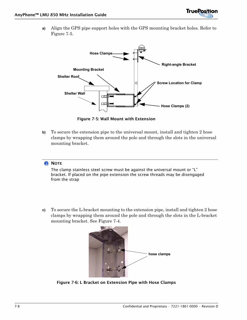
AnyPhone™ LMU 850 MHz Installation Guide
7-8 Confidential and Proprietary • 7221-1861-0000 • Revision D
a) Align the GPS pipe support holes with the GPS mounting bracket holes. Refer to Figure 7-5.
Figure 7-5: Wall Mount with Extension
b) To secure the extension pipe to the universal mount, install and tighten 2 hose clamps by wrapping them around the pole and through the slots in the universal mounting bracket.
NOTE
The clamp stainless steel screw must be against the universal mount or “L” bracket. If placed on the pipe extension the screw threads may be disengaged from the strap
c) To secure the L-bracket mounting to the extension pipe, install and tighten 2 hose clamps by wrapping them around the pole and through the slots in the L-bracket mounting bracket. See Figure 7-4.
Figure 7-6: L Bracket on Extension Pipe with Hose Clamps
Mounting Bracket
Hose Clamps (2)
Right-angle Bracket
Hose Clamps
Shelter Wall
Shelter Roof
Screw Location for Clamp
hose clamps
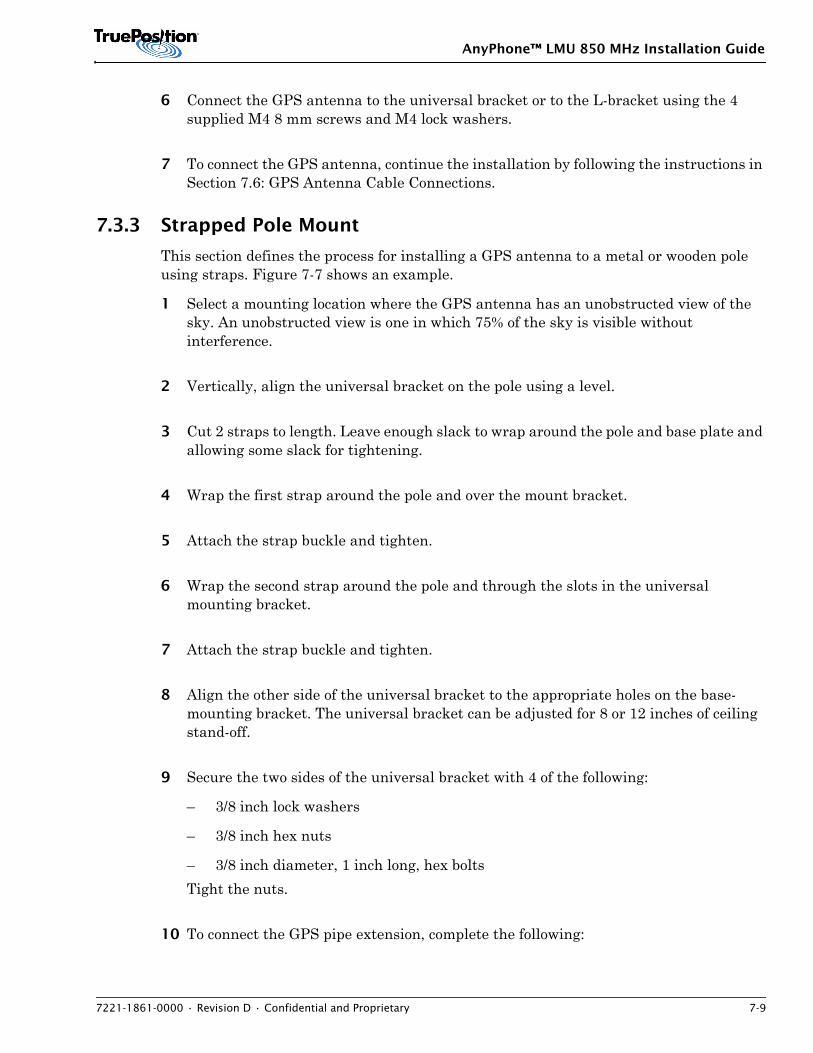
AnyPhone™ LMU 850 MHz Installation Guide
7221-1861-0000 • Revision D • Confidential and Proprietary 7-9
6 Connect the GPS antenna to the universal bracket or to the L-bracket using the 4 supplied M4 8 mm screws and M4 lock washers.
7 To connect the GPS antenna, continue the installation by following the instructions in Section 7.6: GPS Antenna Cable Connections.
7.3.3 Strapped Pole Mount
This section defines the process for installing a GPS antenna to a metal or wooden pole using straps. Figure 7-7 shows an example.
1 Select a mounting location where the GPS antenna has an unobstructed view of the sky. An unobstructed view is one in which 75% of the sky is visible without interference.
2 Vertically, align the universal bracket on the pole using a level.
3 Cut 2 straps to length. Leave enough slack to wrap around the pole and base plate and allowing some slack for tightening.
4 Wrap the first strap around the pole and over the mount bracket.
5 Attach the strap buckle and tighten.
6 Wrap the second strap around the pole and through the slots in the universal mounting bracket.
7 Attach the strap buckle and tighten.
8 Align the other side of the universal bracket to the appropriate holes on the base-mounting bracket. The universal bracket can be adjusted for 8 or 12 inches of ceiling stand-off.
9 Secure the two sides of the universal bracket with 4 of the following:
– 3/8 inch lock washers
– 3/8 inch hex nuts
– 3/8 inch diameter, 1 inch long, hex boltsTight the nuts.
10 To connect the GPS pipe extension, complete the following:
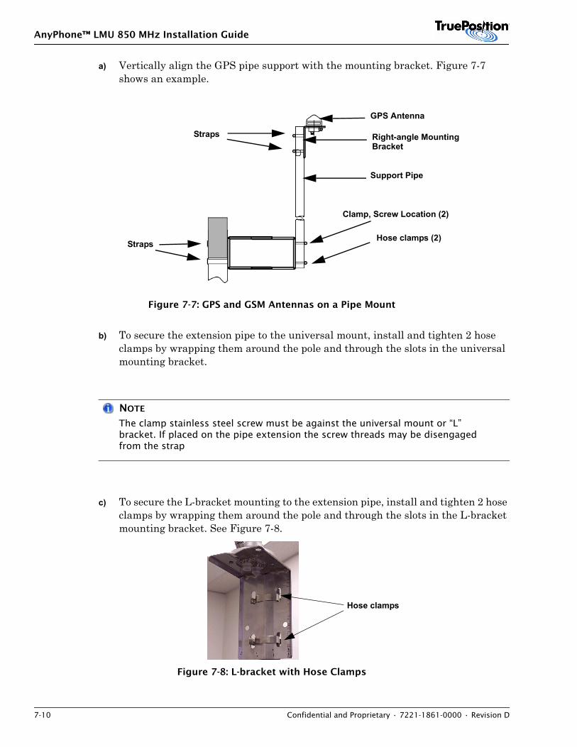
AnyPhone™ LMU 850 MHz Installation Guide
7-10 Confidential and Proprietary • 7221-1861-0000 • Revision D
a) Vertically align the GPS pipe support with the mounting bracket. Figure 7-7 shows an example.
Figure 7-7: GPS and GSM Antennas on a Pipe Mount
b) To secure the extension pipe to the universal mount, install and tighten 2 hose clamps by wrapping them around the pole and through the slots in the universal mounting bracket.
NOTE
The clamp stainless steel screw must be against the universal mount or “L” bracket. If placed on the pipe extension the screw threads may be disengaged from the strap
c) To secure the L-bracket mounting to the extension pipe, install and tighten 2 hose clamps by wrapping them around the pole and through the slots in the L-bracket mounting bracket. See Figure 7-8.
Figure 7-8: L-bracket with Hose Clamps
GPS Antenna
Right-angle Mounting Bracket
Support Pipe
Hose clamps (2)
Straps
Straps
Clamp, Screw Location (2)
Hose clamps
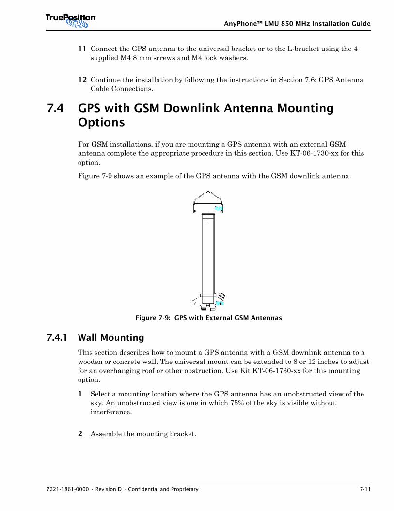
AnyPhone™ LMU 850 MHz Installation Guide
7221-1861-0000 • Revision D • Confidential and Proprietary 7-11
11 Connect the GPS antenna to the universal bracket or to the L-bracket using the 4 supplied M4 8 mm screws and M4 lock washers.
12 Continue the installation by following the instructions in Section 7.6: GPS Antenna Cable Connections.
7.4 GPS with GSM Downlink Antenna Mounting Options
For GSM installations, if you are mounting a GPS antenna with an external GSM antenna complete the appropriate procedure in this section. Use KT-06-1730-xx for this option.
Figure 7-9 shows an example of the GPS antenna with the GSM downlink antenna.
Figure 7-9: GPS with External GSM Antennas
7.4.1 Wall Mounting
This section describes how to mount a GPS antenna with a GSM downlink antenna to a wooden or concrete wall. The universal mount can be extended to 8 or 12 inches to adjust for an overhanging roof or other obstruction. Use Kit KT-06-1730-xx for this mounting option.
1 Select a mounting location where the GPS antenna has an unobstructed view of the sky. An unobstructed view is one in which 75% of the sky is visible without interference.
2 Assemble the mounting bracket.
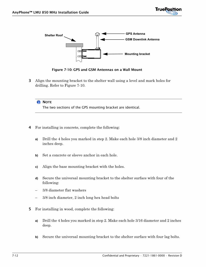
AnyPhone™ LMU 850 MHz Installation Guide
7-12 Confidential and Proprietary • 7221-1861-0000 • Revision D
Figure 7-10: GPS and GSM Antennas on a Wall Mount
3 Align the mounting bracket to the shelter wall using a level and mark holes for drilling. Refer to Figure 7-10.
NOTE
The two sections of the GPS mounting bracket are identical.
4 For installing in concrete, complete the following:
a) Drill the 4 holes you marked in step 2. Make each hole 3/8 inch diameter and 2 inches deep.
b) Set a concrete or sleeve anchor in each hole.
c) Align the base mounting bracket with the holes.
d) Secure the universal mounting bracket to the shelter surface with four of the following:
– 3/8 diameter flat washers
– 3/8 inch diameter, 2 inch long hex head bolts
5 For installing in wood, complete the following:
a) Drill the 4 holes you marked in step 2. Make each hole 3/16 diameter and 2 inches deep.
b) Secure the universal mounting bracket to the shelter surface with four lag bolts.
GPS Antenna
GSM Downlink Antenna
Mounting bracket
Shelter Roof
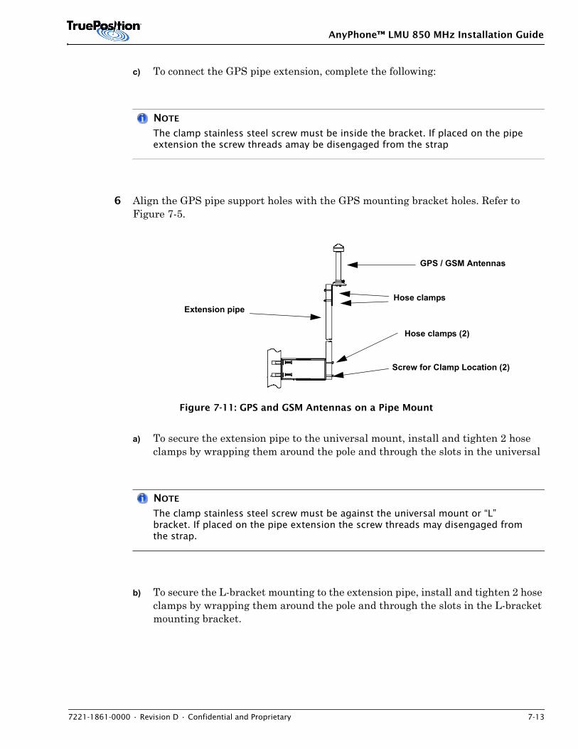
AnyPhone™ LMU 850 MHz Installation Guide
7221-1861-0000 • Revision D • Confidential and Proprietary 7-13
c) To connect the GPS pipe extension, complete the following:
NOTE
The clamp stainless steel screw must be inside the bracket. If placed on the pipe extension the screw threads amay be disengaged from the strap
6 Align the GPS pipe support holes with the GPS mounting bracket holes. Refer to Figure 7-5.
Figure 7-11: GPS and GSM Antennas on a Pipe Mount
a) To secure the extension pipe to the universal mount, install and tighten 2 hose clamps by wrapping them around the pole and through the slots in the universal
NOTE
The clamp stainless steel screw must be against the universal mount or “L” bracket. If placed on the pipe extension the screw threads may disengaged from the strap.
b) To secure the L-bracket mounting to the extension pipe, install and tighten 2 hose clamps by wrapping them around the pole and through the slots in the L-bracket mounting bracket.
GPS / GSM Antennas
Hose clamps
Hose clamps (2)
Extension pipe
Screw for Clamp Location (2)
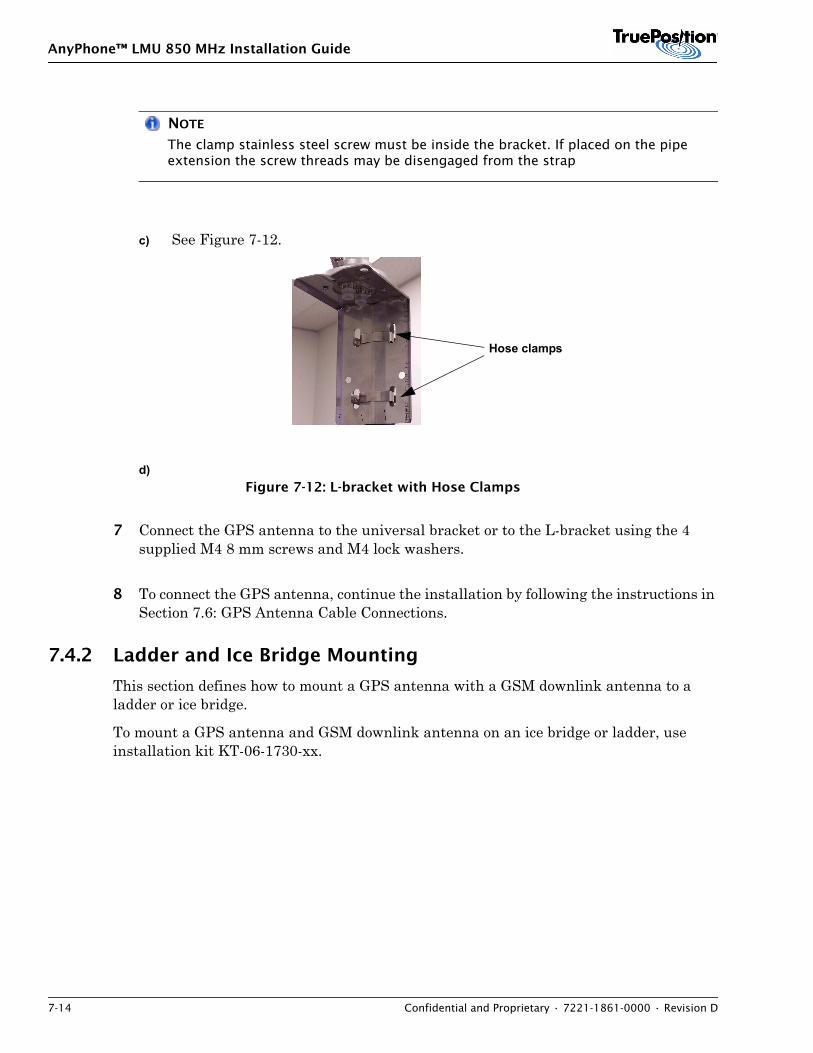
AnyPhone™ LMU 850 MHz Installation Guide
7-14 Confidential and Proprietary • 7221-1861-0000 • Revision D
NOTE
The clamp stainless steel screw must be inside the bracket. If placed on the pipe extension the screw threads may be disengaged from the strap
c) See Figure 7-12.
d)Figure 7-12: L-bracket with Hose Clamps
7 Connect the GPS antenna to the universal bracket or to the L-bracket using the 4 supplied M4 8 mm screws and M4 lock washers.
8 To connect the GPS antenna, continue the installation by following the instructions in Section 7.6: GPS Antenna Cable Connections.
7.4.2 Ladder and Ice Bridge Mounting
This section defines how to mount a GPS antenna with a GSM downlink antenna to a ladder or ice bridge.
To mount a GPS antenna and GSM downlink antenna on an ice bridge or ladder, use installation kit KT-06-1730-xx.
Hose clamps
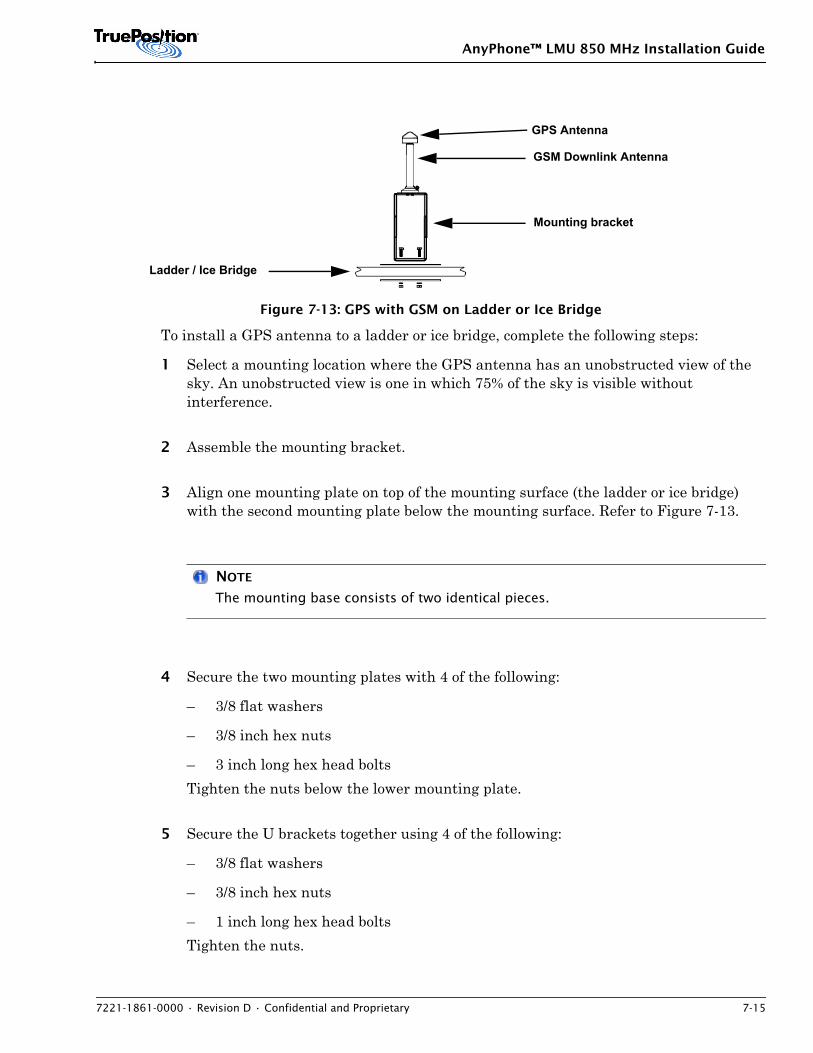
AnyPhone™ LMU 850 MHz Installation Guide
7221-1861-0000 • Revision D • Confidential and Proprietary 7-15
Figure 7-13: GPS with GSM on Ladder or Ice Bridge
To install a GPS antenna to a ladder or ice bridge, complete the following steps:
1 Select a mounting location where the GPS antenna has an unobstructed view of the sky. An unobstructed view is one in which 75% of the sky is visible without interference.
2 Assemble the mounting bracket.
3 Align one mounting plate on top of the mounting surface (the ladder or ice bridge) with the second mounting plate below the mounting surface. Refer to Figure 7-13.
NOTE
The mounting base consists of two identical pieces.
4 Secure the two mounting plates with 4 of the following:
– 3/8 flat washers
– 3/8 inch hex nuts
– 3 inch long hex head bolts Tighten the nuts below the lower mounting plate.
5 Secure the U brackets together using 4 of the following:
– 3/8 flat washers
– 3/8 inch hex nuts
– 1 inch long hex head bolts Tighten the nuts.
GSM Downlink Antenna
GPS Antenna
Ladder / Ice Bridge
Mounting bracket
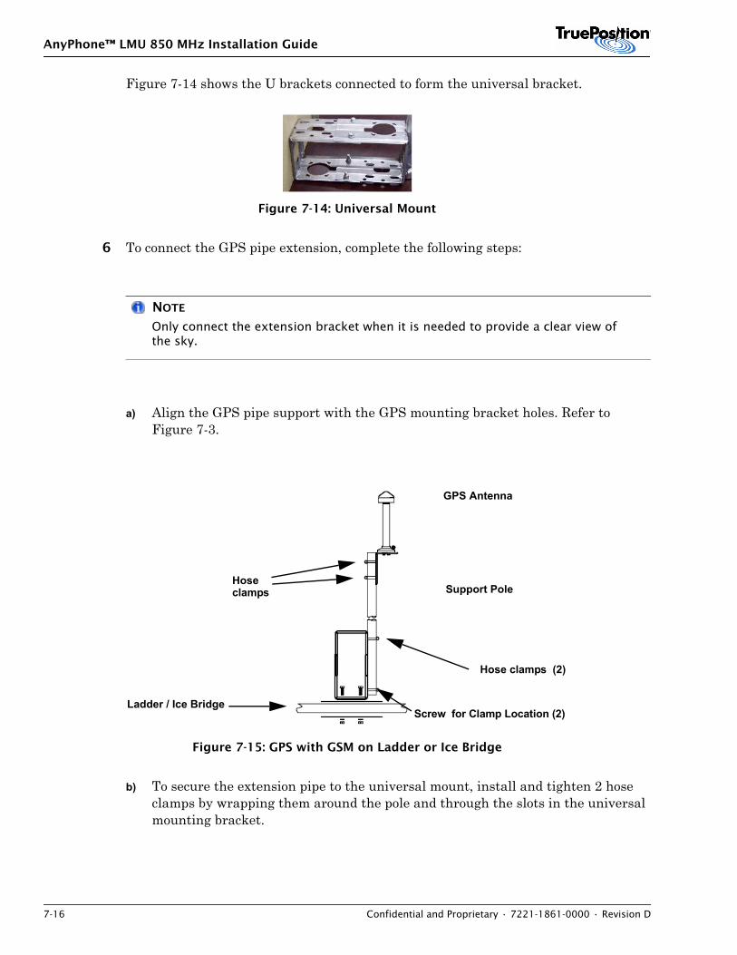
AnyPhone™ LMU 850 MHz Installation Guide
7-16 Confidential and Proprietary • 7221-1861-0000 • Revision D
Figure 7-14 shows the U brackets connected to form the universal bracket.
Figure 7-14: Universal Mount
6 To connect the GPS pipe extension, complete the following steps:
NOTE
Only connect the extension bracket when it is needed to provide a clear view of the sky.
a) Align the GPS pipe support with the GPS mounting bracket holes. Refer to Figure 7-3.
Figure 7-15: GPS with GSM on Ladder or Ice Bridge
b) To secure the extension pipe to the universal mount, install and tighten 2 hose clamps by wrapping them around the pole and through the slots in the universal mounting bracket.
GPS Antenna
Support Pole
Ladder / Ice Bridge
Hoseclamps
Hose clamps (2)
Screw for Clamp Location (2)
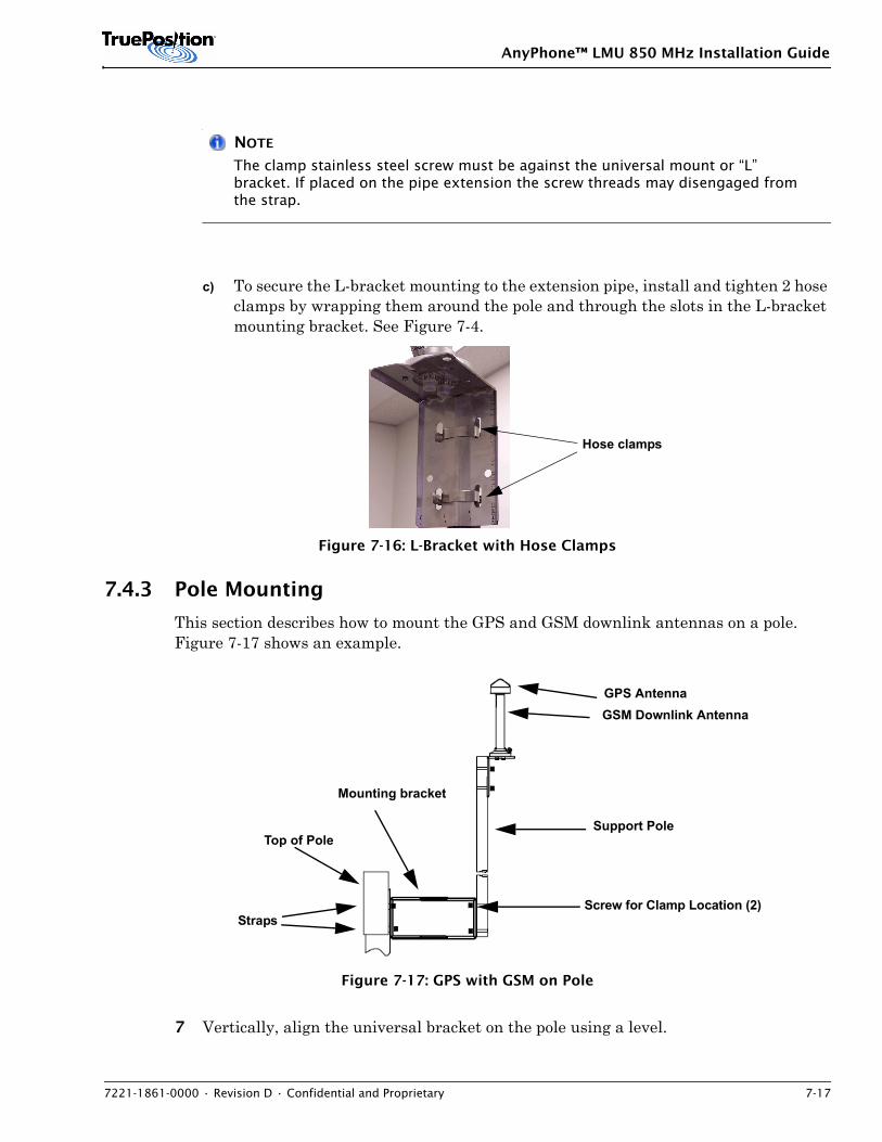
AnyPhone™ LMU 850 MHz Installation Guide
7221-1861-0000 • Revision D • Confidential and Proprietary 7-17
NOTE
The clamp stainless steel screw must be against the universal mount or “L” bracket. If placed on the pipe extension the screw threads may disengaged from the strap.
c) To secure the L-bracket mounting to the extension pipe, install and tighten 2 hose clamps by wrapping them around the pole and through the slots in the L-bracket mounting bracket. See Figure 7-4.
Figure 7-16: L-Bracket with Hose Clamps
7.4.3 Pole Mounting
This section describes how to mount the GPS and GSM downlink antennas on a pole. Figure 7-17 shows an example.
Figure 7-17: GPS with GSM on Pole
7 Vertically, align the universal bracket on the pole using a level.
Hose clamps
Straps
Support Pole
GPS AntennaGSM Downlink Antenna
Top of Pole
Mounting bracket
Screw for Clamp Location (2)
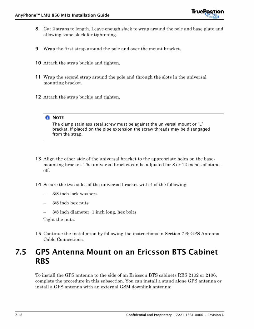
AnyPhone™ LMU 850 MHz Installation Guide
7-18 Confidential and Proprietary • 7221-1861-0000 • Revision D
8 Cut 2 straps to length. Leave enough slack to wrap around the pole and base plate and allowing some slack for tightening.
9 Wrap the first strap around the pole and over the mount bracket.
10 Attach the strap buckle and tighten.
11 Wrap the second strap around the pole and through the slots in the universal mounting bracket.
12 Attach the strap buckle and tighten.
NOTE
The clamp stainless steel screw must be against the universal mount or “L” bracket. If placed on the pipe extension the screw threads may be disengaged from the strap.
13 Align the other side of the universal bracket to the appropriate holes on the base-mounting bracket. The universal bracket can be adjusted for 8 or 12 inches of stand-off.
14 Secure the two sides of the universal bracket with 4 of the following:
– 3/8 inch lock washers
– 3/8 inch hex nuts
– 3/8 inch diameter, 1 inch long, hex boltsTight the nuts.
15 Continue the installation by following the instructions in Section 7.6: GPS Antenna Cable Connections.
7.5 GPS Antenna Mount on an Ericsson BTS Cabinet RBS
To install the GPS antenna to the side of an Ericsson BTS cabinets RBS 2102 or 2106, complete the procedure in this subsection. You can install a stand alone GPS antenna or install a GPS antenna with an external GSM downlink antenna:
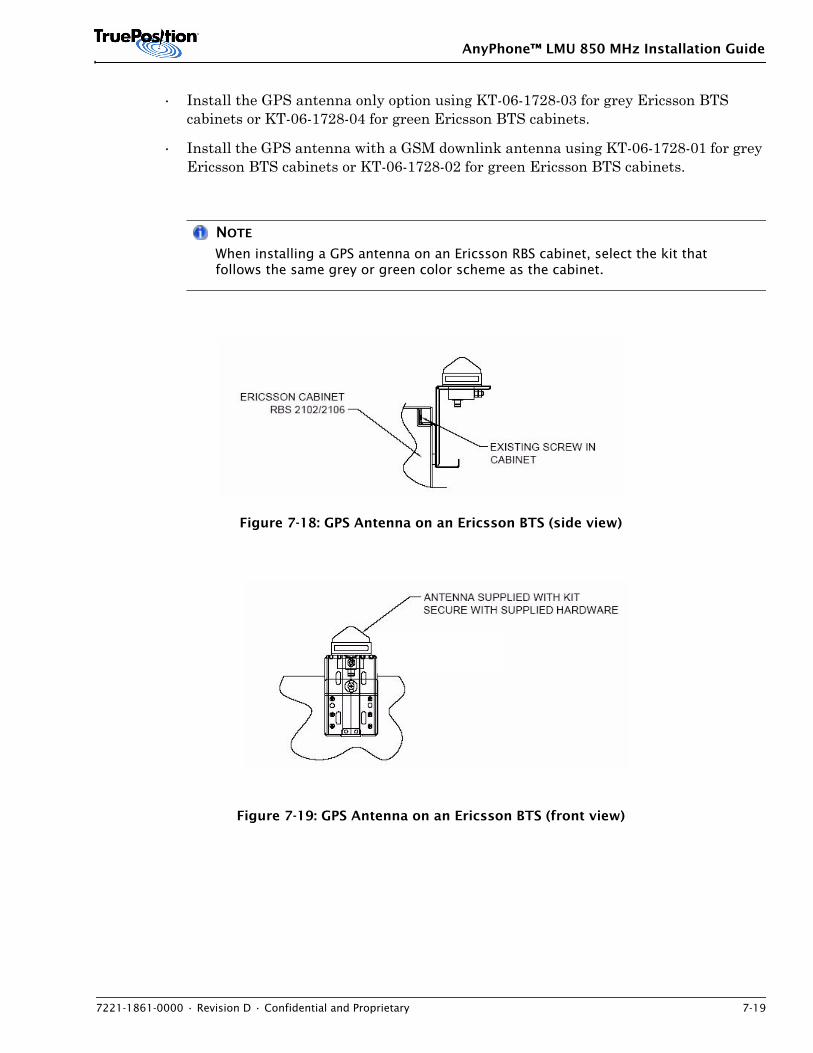
AnyPhone™ LMU 850 MHz Installation Guide
7221-1861-0000 • Revision D • Confidential and Proprietary 7-19
• Install the GPS antenna only option using KT-06-1728-03 for grey Ericsson BTS cabinets or KT-06-1728-04 for green Ericsson BTS cabinets.
• Install the GPS antenna with a GSM downlink antenna using KT-06-1728-01 for grey Ericsson BTS cabinets or KT-06-1728-02 for green Ericsson BTS cabinets.
NOTE
When installing a GPS antenna on an Ericsson RBS cabinet, select the kit that follows the same grey or green color scheme as the cabinet.
Figure 7-18: GPS Antenna on an Ericsson BTS (side view)
Figure 7-19: GPS Antenna on an Ericsson BTS (front view)
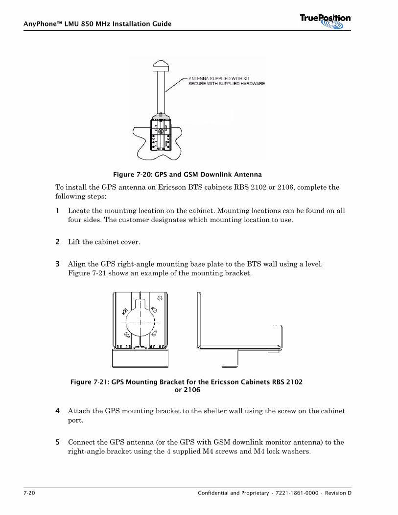
AnyPhone™ LMU 850 MHz Installation Guide
7-20 Confidential and Proprietary • 7221-1861-0000 • Revision D
Figure 7-20: GPS and GSM Downlink Antenna
To install the GPS antenna on Ericsson BTS cabinets RBS 2102 or 2106, complete the following steps:
1 Locate the mounting location on the cabinet. Mounting locations can be found on all four sides. The customer designates which mounting location to use.
2 Lift the cabinet cover.
3 Align the GPS right-angle mounting base plate to the BTS wall using a level. Figure 7-21 shows an example of the mounting bracket.
Figure 7-21: GPS Mounting Bracket for the Ericsson Cabinets RBS 2102 or 2106
4 Attach the GPS mounting bracket to the shelter wall using the screw on the cabinet port.
5 Connect the GPS antenna (or the GPS with GSM downlink monitor antenna) to the right-angle bracket using the 4 supplied M4 screws and M4 lock washers.
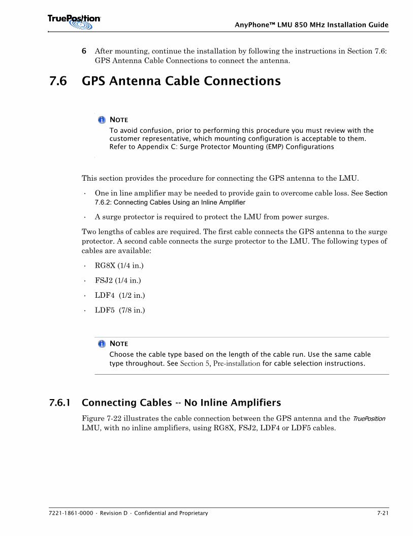
AnyPhone™ LMU 850 MHz Installation Guide
7221-1861-0000 • Revision D • Confidential and Proprietary 7-21
6 After mounting, continue the installation by following the instructions in Section 7.6: GPS Antenna Cable Connections to connect the antenna.
7.6 GPS Antenna Cable Connections
NOTE
To avoid confusion, prior to performing this procedure you must review with the customer representative, which mounting configuration is acceptable to them. Refer to Appendix C: Surge Protector Mounting (EMP) Configurations
This section provides the procedure for connecting the GPS antenna to the LMU.
• One in line amplifier may be needed to provide gain to overcome cable loss. See Section 7.6.2: Connecting Cables Using an Inline Amplifier
• A surge protector is required to protect the LMU from power surges.
Two lengths of cables are required. The first cable connects the GPS antenna to the surge protector. A second cable connects the surge protector to the LMU. The following types of cables are available:
• RG8X (1/4 in.)
• FSJ2 (1/4 in.)
• LDF4 (1/2 in.)
• LDF5 (7/8 in.)
NOTE
Choose the cable type based on the length of the cable run. Use the same cable type throughout. See Section 5, Pre-installation for cable selection instructions.
7.6.1 Connecting Cables -- No Inline Amplifiers
Figure 7-22 illustrates the cable connection between the GPS antenna and the TruePosition LMU, with no inline amplifiers, using RG8X, FSJ2, LDF4 or LDF5 cables.
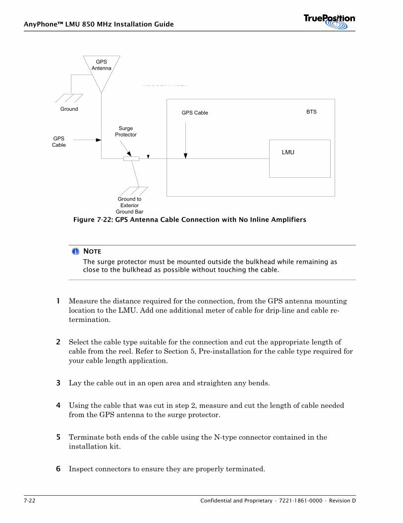
AnyPhone™ LMU 850 MHz Installation Guide
7-22 Confidential and Proprietary • 7221-1861-0000 • Revision D
Figure 7-22: GPS Antenna Cable Connection with No Inline Amplifiers
NOTE
The surge protector must be mounted outside the bulkhead while remaining as close to the bulkhead as possible without touching the cable.
1 Measure the distance required for the connection, from the GPS antenna mounting location to the LMU. Add one additional meter of cable for drip-line and cable re-termination.
2 Select the cable type suitable for the connection and cut the appropriate length of cable from the reel. Refer to Section 5, Pre-installation for the cable type required for your cable length application.
3 Lay the cable out in an open area and straighten any bends.
4 Using the cable that was cut in step 2, measure and cut the length of cable needed from the GPS antenna to the surge protector.
5 Terminate both ends of the cable using the N-type connector contained in the installation kit.
6 Inspect connectors to ensure they are properly terminated.
GPSAntenna
LMU
GPSCable
Ground toExterior
Ground Bar
SurgeProtector
BTSGPS Cable
The cable from surgeprotector to shelterentrance cannot bemore than 1 meter.
Ground
LMU
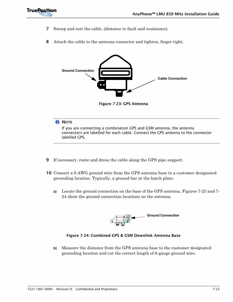
AnyPhone™ LMU 850 MHz Installation Guide
7221-1861-0000 • Revision D • Confidential and Proprietary 7-23
7 Sweep and test the cable, (distance to fault and resistance).
8 Attach the cable to the antenna connector and tighten, finger tight.
Figure 7-23: GPS Antenna
NOTE
If you are connecting a combination GPS and GSM antenna, the antenna connectors are labelled for each cable. Connect the GPS antenna to the connector labelled GPS.
9 If necessary, route and dress the cable along the GPS pipe support.
10 Connect a 6 AWG ground wire from the GPS antenna base to a customer designated grounding location. Typically, a ground bar at the hatch plate.
a) Locate the ground connection on the base of the GPS antenna. Figures 7-23 and 7-24 show the ground connection locations on the antenna.
Figure 7-24: Combined GPS & GSM Downlink Antenna Base
b) Measure the distance from the GPS antenna base to the customer designated grounding location and cut the correct length of 6-gauge ground wire.
Cable Connection
Ground Connection
Ground Connection
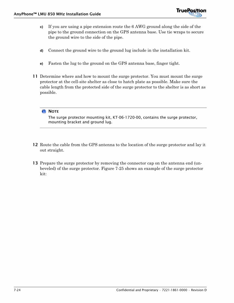
AnyPhone™ LMU 850 MHz Installation Guide
7-24 Confidential and Proprietary • 7221-1861-0000 • Revision D
c) If you are using a pipe extension route the 6 AWG ground along the side of the pipe to the ground connection on the GPS antenna base. Use tie wraps to secure the ground wire to the side of the pipe.
d) Connect the ground wire to the ground lug include in the installation kit.
e) Fasten the lug to the ground on the GPS antenna base, finger tight.
11 Determine where and how to mount the surge protector. You must mount the surge protector at the cell-site shelter as close to hatch plate as possible. Make sure the cable length from the protected side of the surge protector to the shelter is as short as possible.
NOTE
The surge protector mounting kit, KT-06-1720-00, contains the surge protector, mounting bracket and ground lug.
12 Route the cable from the GPS antenna to the location of the surge protector and lay it out straight.
13 Prepare the surge protector by removing the connector cap on the antenna end (un-beveled) of the surge protector. Figure 7-25 shows an example of the surge protector kit:
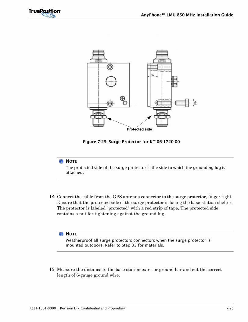
AnyPhone™ LMU 850 MHz Installation Guide
7221-1861-0000 • Revision D • Confidential and Proprietary 7-25
Figure 7-25: Surge Protector for KT 06-1720-00
NOTE
The protected side of the surge protector is the side to which the grounding lug is attached.
14 Connect the cable from the GPS antenna connector to the surge protector, finger tight. Ensure that the protected side of the surge protector is facing the base-station shelter. The protector is labeled “protected” with a red strip of tape. The protected side contains a nut for tightening against the ground lug.
NOTE
Weatherproof all surge protectors connectors when the surge protector is mounted outdoors. Refer to Step 33 for materials.
15 Measure the distance to the base station exterior ground bar and cut the correct length of 6-gauge ground wire.
Protected side
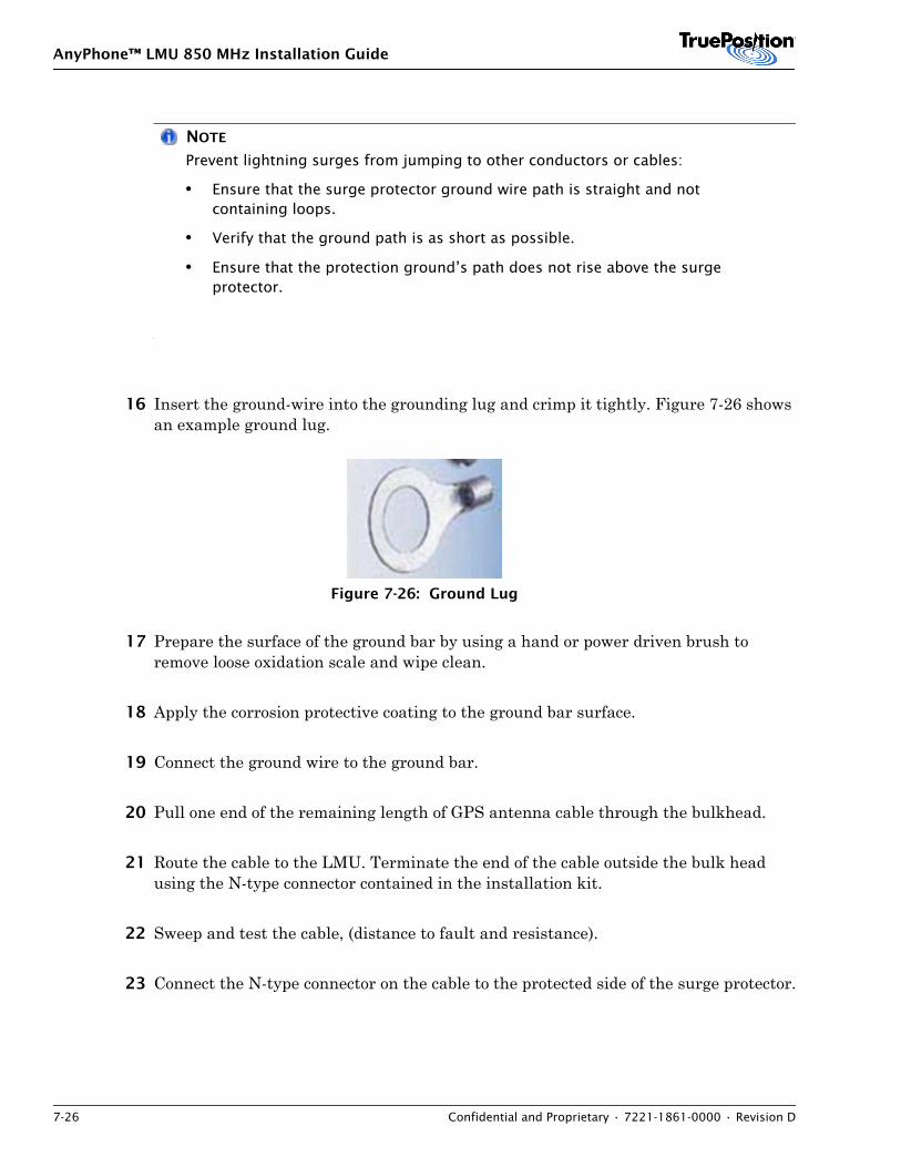
AnyPhone™ LMU 850 MHz Installation Guide
7-26 Confidential and Proprietary • 7221-1861-0000 • Revision D
NOTE
Prevent lightning surges from jumping to other conductors or cables:
• Ensure that the surge protector ground wire path is straight and not containing loops.
• Verify that the ground path is as short as possible.
• Ensure that the protection ground’s path does not rise above the surge protector.
16 Insert the ground-wire into the grounding lug and crimp it tightly. Figure 7-26 shows an example ground lug.
Figure 7-26: Ground Lug
17 Prepare the surface of the ground bar by using a hand or power driven brush to remove loose oxidation scale and wipe clean.
18 Apply the corrosion protective coating to the ground bar surface.
19 Connect the ground wire to the ground bar.
20 Pull one end of the remaining length of GPS antenna cable through the bulkhead.
21 Route the cable to the LMU. Terminate the end of the cable outside the bulk head using the N-type connector contained in the installation kit.
22 Sweep and test the cable, (distance to fault and resistance).
23 Connect the N-type connector on the cable to the protected side of the surge protector.
AnyPhone™ LMU 850 MHz Installation Guide
7221-1861-0000 • Revision D • Confidential and Proprietary 7-27
24 Terminate the other end of the cable with an SMA connector contained in the installation kit.
Figure 7-27: SMA Connector
25 Using an SMA-torque wrench, secure the GPS jumper connector to the GPS port on the LMU.
26 Inspect connectors to ensure they are properly terminated.
27 Coil the cable leaving enough slack to reach the LMU location, in case of re-termination.
28 Weatherproof all external connections by wrapping the cable connections with the following:
i. One layer of vinyl tape (preferably Scotch Brand #88 Electrical Tape),
ii. One layer of mastic tape, extending past the vinyl tape.
29 Three layers of vinyl tape, extending past the mastic tape, (preferably Scotch Brand #88 Electrical Tape)
NOTE
Weatherproof all surge protectors connectors when the surge protector is mounted outdoors. Refer to Step 28 for materials.
7.6.2 Connecting Cables Using an Inline Amplifier
Figure 7-28 illustrates the cable connection between the GPS antenna and the LMU, with one inline amplifier using an RG8X, FSJ2, LDF4 or LDF5 cable.
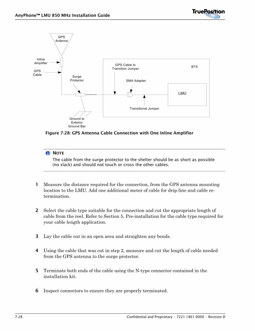
AnyPhone™ LMU 850 MHz Installation Guide
7-28 Confidential and Proprietary • 7221-1861-0000 • Revision D
Figure 7-28: GPS Antenna Cable Connection with One Inline Amplifier
NOTE
The cable from the surge protector to the shelter should be as short as possible (no slack) and should not touch or cross the other cables.
1 Measure the distance required for the connection, from the GPS antenna mounting location to the LMU. Add one additional meter of cable for drip-line and cable re-termination.
2 Select the cable type suitable for the connection and cut the appropriate length of cable from the reel. Refer to Section 5, Pre-installation for the cable type required for your cable length application.
3 Lay the cable out in an open area and straighten any bends.
4 Using the cable that was cut in step 2, measure and cut the length of cable needed from the GPS antenna to the surge protector.
5 Terminate both ends of the cable using the N-type connector contained in the installation kit.
6 Inspect connectors to ensure they are properly terminated.
GPSAntenna
LMU
GPSCable
SMA Adapter
Transitional Jumper
Ground toExterior
Ground Bar
SurgeProtector
BTSGPS Cable toTransition Jumper
The cable from surgeprotector to shelterentrance cannot bemore than 1 meter.
InlineAmplifier
LMU
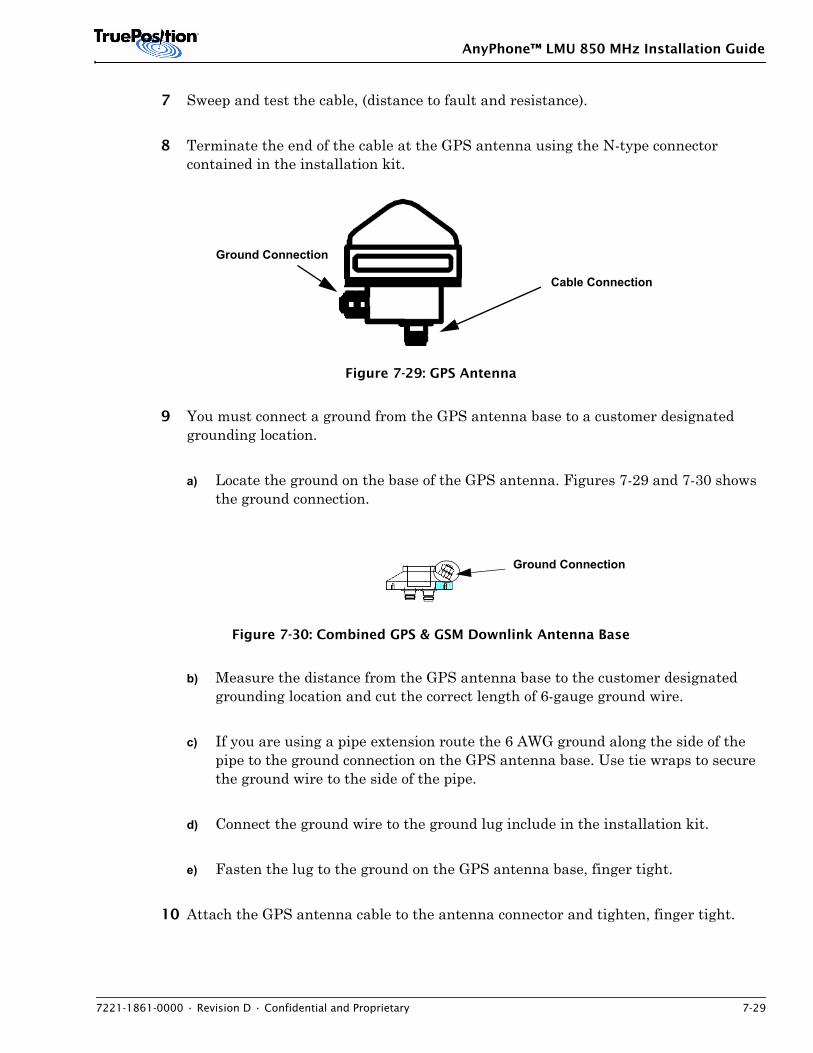
AnyPhone™ LMU 850 MHz Installation Guide
7221-1861-0000 • Revision D • Confidential and Proprietary 7-29
7 Sweep and test the cable, (distance to fault and resistance).
8 Terminate the end of the cable at the GPS antenna using the N-type connector contained in the installation kit.
Figure 7-29: GPS Antenna
9 You must connect a ground from the GPS antenna base to a customer designated grounding location.
a) Locate the ground on the base of the GPS antenna. Figures 7-29 and 7-30 shows the ground connection.
Figure 7-30: Combined GPS & GSM Downlink Antenna Base
b) Measure the distance from the GPS antenna base to the customer designated grounding location and cut the correct length of 6-gauge ground wire.
c) If you are using a pipe extension route the 6 AWG ground along the side of the pipe to the ground connection on the GPS antenna base. Use tie wraps to secure the ground wire to the side of the pipe.
d) Connect the ground wire to the ground lug include in the installation kit.
e) Fasten the lug to the ground on the GPS antenna base, finger tight.
10 Attach the GPS antenna cable to the antenna connector and tighten, finger tight.
Cable Connection
Ground Connection
Ground Connection
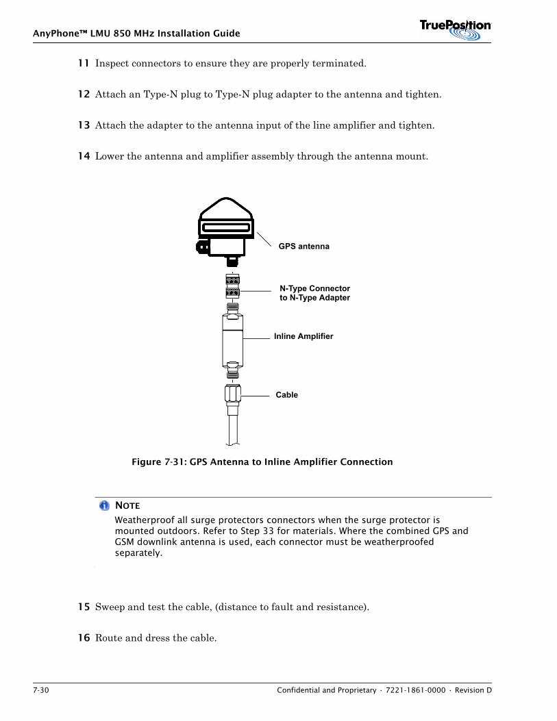
AnyPhone™ LMU 850 MHz Installation Guide
7-30 Confidential and Proprietary • 7221-1861-0000 • Revision D
11 Inspect connectors to ensure they are properly terminated.
12 Attach an Type-N plug to Type-N plug adapter to the antenna and tighten.
13 Attach the adapter to the antenna input of the line amplifier and tighten.
14 Lower the antenna and amplifier assembly through the antenna mount.
Figure 7-31: GPS Antenna to Inline Amplifier Connection
NOTE
Weatherproof all surge protectors connectors when the surge protector is mounted outdoors. Refer to Step 33 for materials. Where the combined GPS and GSM downlink antenna is used, each connector must be weatherproofed separately.
15 Sweep and test the cable, (distance to fault and resistance).
16 Route and dress the cable.
GPS antenna
N-Type Connectorto N-Type Adapter
Inline Amplifier
Cable
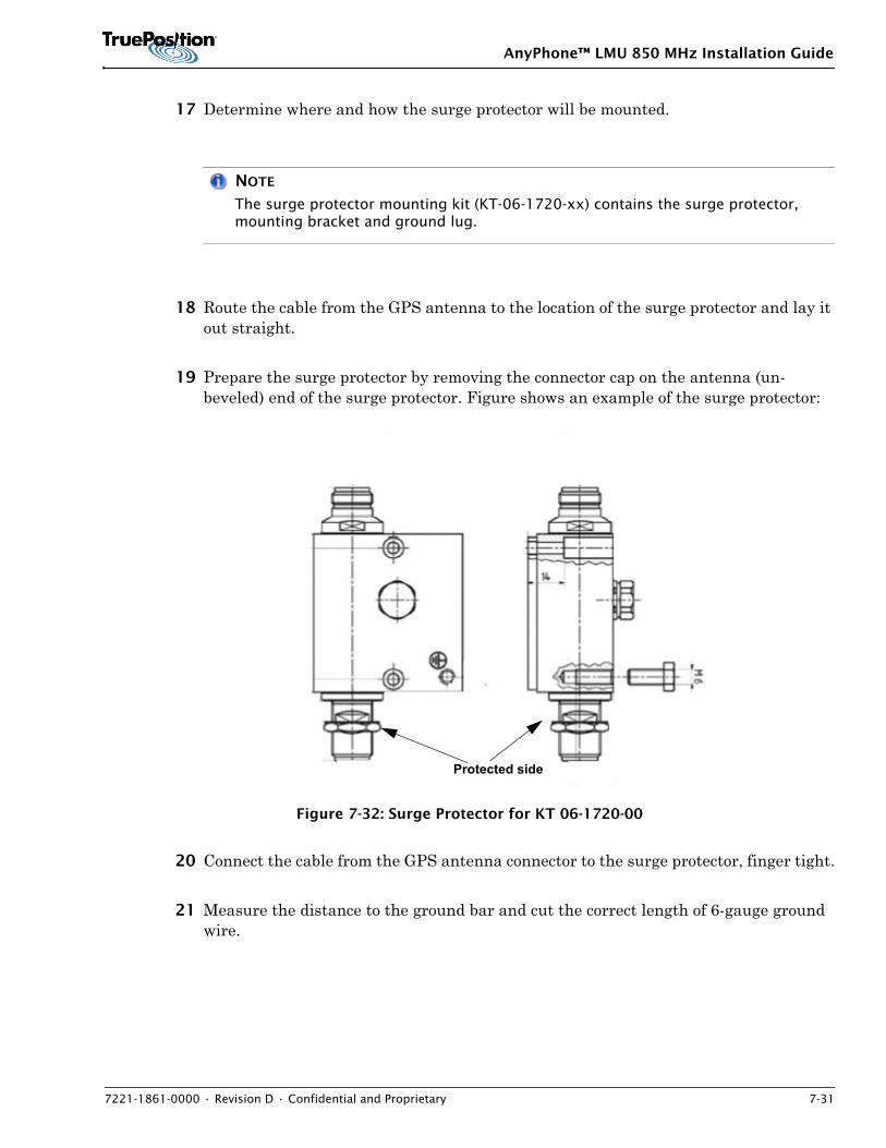
AnyPhone™ LMU 850 MHz Installation Guide
7221-1861-0000 • Revision D • Confidential and Proprietary 7-31
17 Determine where and how the surge protector will be mounted.
NOTE
The surge protector mounting kit (KT-06-1720-xx) contains the surge protector, mounting bracket and ground lug.
18 Route the cable from the GPS antenna to the location of the surge protector and lay it out straight.
19 Prepare the surge protector by removing the connector cap on the antenna (un-beveled) end of the surge protector. Figure shows an example of the surge protector:
Figure 7-32: Surge Protector for KT 06-1720-00
20 Connect the cable from the GPS antenna connector to the surge protector, finger tight.
21 Measure the distance to the ground bar and cut the correct length of 6-gauge ground wire.
Protected side
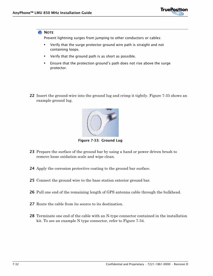
AnyPhone™ LMU 850 MHz Installation Guide
7-32 Confidential and Proprietary • 7221-1861-0000 • Revision D
NOTE
Prevent lightning surges from jumping to other conductors or cables:
• Verify that the surge protector ground wire path is straight and not containing loops.
• Verify that the ground path is as short as possible.
• Ensure that the protection ground’s path does not rise above the surge protector.
22 Insert the ground-wire into the ground lug and crimp it tightly. Figure 7-33 shows an example ground lug.
Figure 7-33: Ground Lug
23 Prepare the surface of the ground bar by using a hand or power driven brush to remove loose oxidation scale and wipe clean.
24 Apply the corrosion protective coating to the ground bar surface.
25 Connect the ground wire to the base station exterior ground bar.
26 Pull one end of the remaining length of GPS antenna cable through the bulkhead.
27 Route the cable from its source to its destination.
28 Terminate one end of the cable with an N-type connector contained in the installation kit. To see an example N type connector, refer to Figure 7-34.
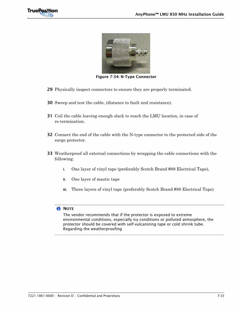
AnyPhone™ LMU 850 MHz Installation Guide
7221-1861-0000 • Revision D • Confidential and Proprietary 7-33
Figure 7-34: N-Type Connector
29 Physically inspect connectors to ensure they are properly terminated.
30 Sweep and test the cable, (distance to fault and resistance).
31 Coil the cable leaving enough slack to reach the LMU location, in case of re-termination.
32 Connect the end of the cable with the N-type connector to the protected side of the surge protector.
33 Weatherproof all external connections by wrapping the cable connections with the following:
i. One layer of vinyl tape (preferably Scotch Brand #88 Electrical Tape),
ii. One layer of mastic tape
iii. Three layers of vinyl tape (preferably Scotch Brand #88 Electrical Tape)
NOTE
The vendor recommends that if the protector is exposed to extreme environmental conditions, especially icy conditions or polluted atmosphere, the protector should be covered with self-vulcanizing tape or cold shrink tube. Regarding the weatherproofing
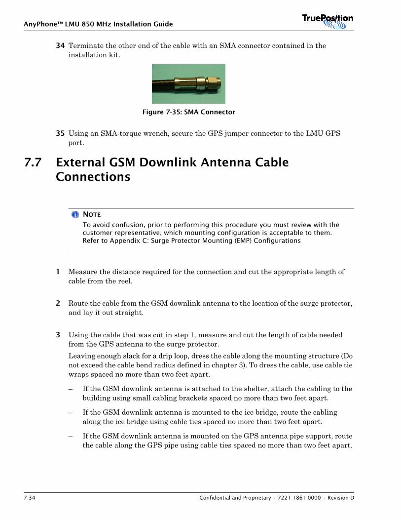
AnyPhone™ LMU 850 MHz Installation Guide
7-34 Confidential and Proprietary • 7221-1861-0000 • Revision D
34 Terminate the other end of the cable with an SMA connector contained in the installation kit.
Figure 7-35: SMA Connector
35 Using an SMA-torque wrench, secure the GPS jumper connector to the LMU GPS port.
7.7 External GSM Downlink Antenna Cable Connections
NOTE
To avoid confusion, prior to performing this procedure you must review with the customer representative, which mounting configuration is acceptable to them. Refer to Appendix C: Surge Protector Mounting (EMP) Configurations
1 Measure the distance required for the connection and cut the appropriate length of cable from the reel.
2 Route the cable from the GSM downlink antenna to the location of the surge protector, and lay it out straight.
3 Using the cable that was cut in step 1, measure and cut the length of cable needed from the GPS antenna to the surge protector.Leaving enough slack for a drip loop, dress the cable along the mounting structure (Do not exceed the cable bend radius defined in chapter 3). To dress the cable, use cable tie wraps spaced no more than two feet apart.
– If the GSM downlink antenna is attached to the shelter, attach the cabling to the building using small cabling brackets spaced no more than two feet apart.
– If the GSM downlink antenna is mounted to the ice bridge, route the cabling along the ice bridge using cable ties spaced no more than two feet apart.
– If the GSM downlink antenna is mounted on the GPS antenna pipe support, route the cable along the GPS pipe using cable ties spaced no more than two feet apart.
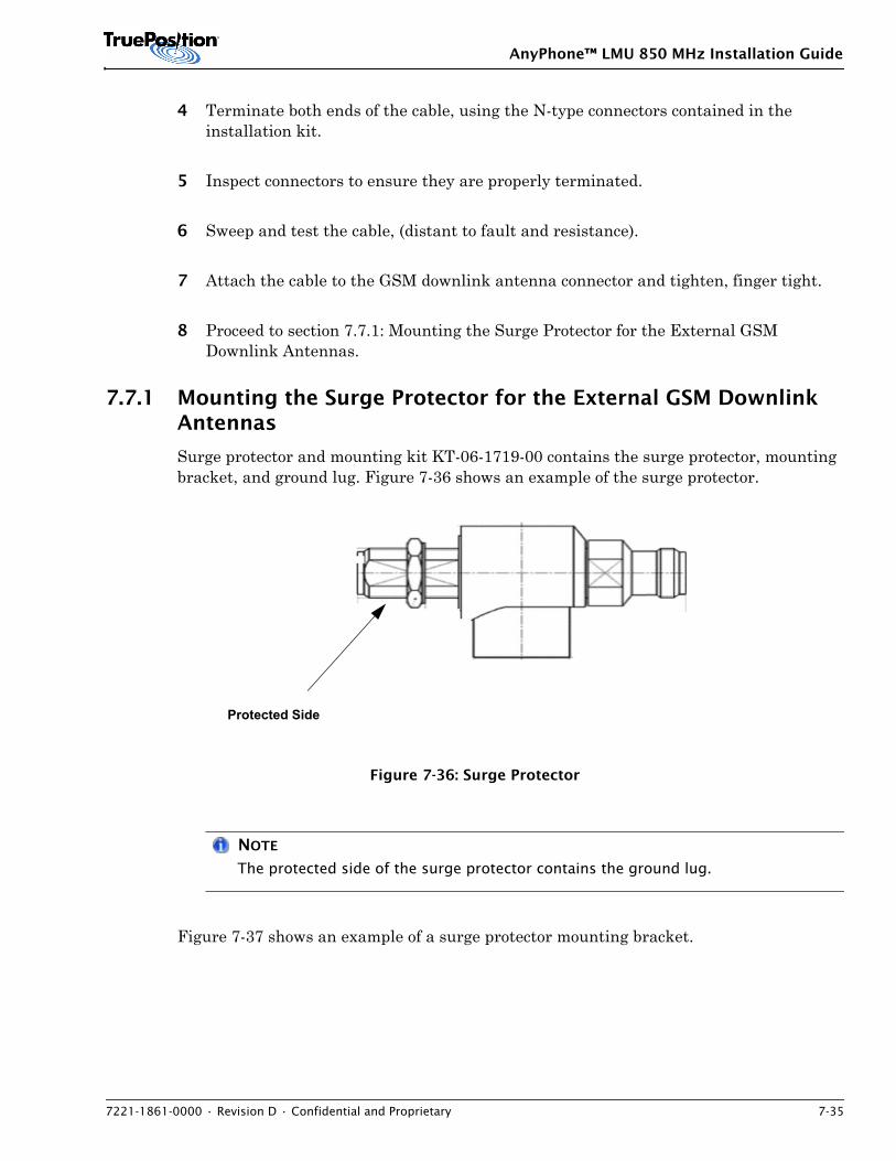
AnyPhone™ LMU 850 MHz Installation Guide
7221-1861-0000 • Revision D • Confidential and Proprietary 7-35
4 Terminate both ends of the cable, using the N-type connectors contained in the installation kit.
5 Inspect connectors to ensure they are properly terminated.
6 Sweep and test the cable, (distant to fault and resistance).
7 Attach the cable to the GSM downlink antenna connector and tighten, finger tight.
8 Proceed to section 7.7.1: Mounting the Surge Protector for the External GSM Downlink Antennas.
7.7.1 Mounting the Surge Protector for the External GSM Downlink Antennas
Surge protector and mounting kit KT-06-1719-00 contains the surge protector, mounting bracket, and ground lug. Figure 7-36 shows an example of the surge protector.
Figure 7-36: Surge Protector
NOTE
The protected side of the surge protector contains the ground lug.
Figure 7-37 shows an example of a surge protector mounting bracket.
Protected Side
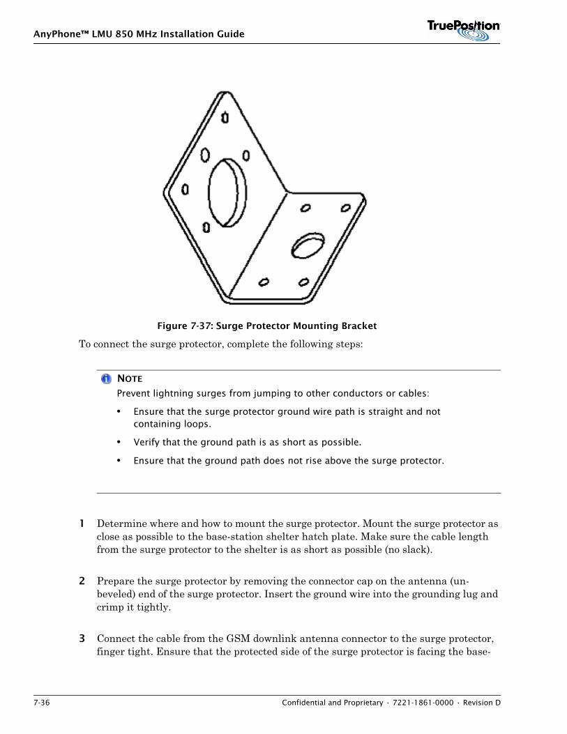
AnyPhone™ LMU 850 MHz Installation Guide
7-36 Confidential and Proprietary • 7221-1861-0000 • Revision D
Figure 7-37: Surge Protector Mounting Bracket
To connect the surge protector, complete the following steps:
NOTE
Prevent lightning surges from jumping to other conductors or cables:
• Ensure that the surge protector ground wire path is straight and not containing loops.
• Verify that the ground path is as short as possible.
• Ensure that the ground path does not rise above the surge protector.
1 Determine where and how to mount the surge protector. Mount the surge protector as close as possible to the base-station shelter hatch plate. Make sure the cable length from the surge protector to the shelter is as short as possible (no slack).
2 Prepare the surge protector by removing the connector cap on the antenna (un-beveled) end of the surge protector. Insert the ground wire into the grounding lug and crimp it tightly.
3 Connect the cable from the GSM downlink antenna connector to the surge protector, finger tight. Ensure that the protected side of the surge protector is facing the base-
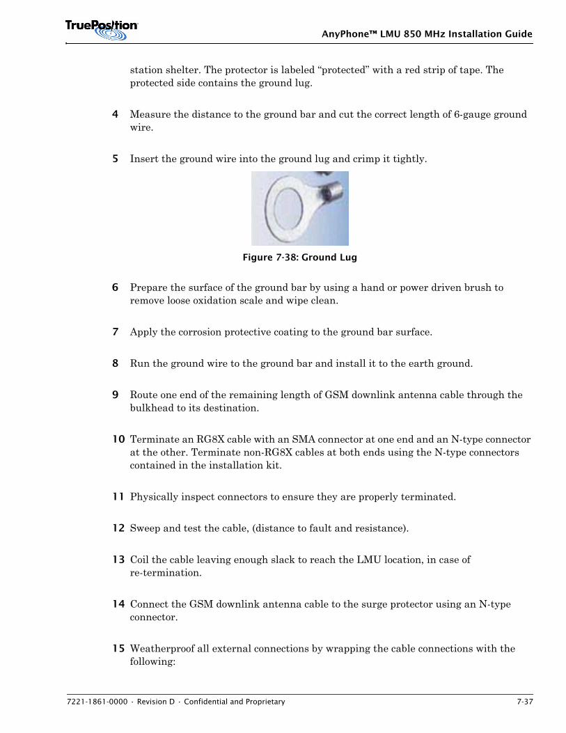
AnyPhone™ LMU 850 MHz Installation Guide
7221-1861-0000 • Revision D • Confidential and Proprietary 7-37
station shelter. The protector is labeled “protected” with a red strip of tape. The protected side contains the ground lug.
4 Measure the distance to the ground bar and cut the correct length of 6-gauge ground wire.
5 Insert the ground wire into the ground lug and crimp it tightly.
Figure 7-38: Ground Lug
6 Prepare the surface of the ground bar by using a hand or power driven brush to remove loose oxidation scale and wipe clean.
7 Apply the corrosion protective coating to the ground bar surface.
8 Run the ground wire to the ground bar and install it to the earth ground.
9 Route one end of the remaining length of GSM downlink antenna cable through the bulkhead to its destination.
10 Terminate an RG8X cable with an SMA connector at one end and an N-type connector at the other. Terminate non-RG8X cables at both ends using the N-type connectors contained in the installation kit.
11 Physically inspect connectors to ensure they are properly terminated.
12 Sweep and test the cable, (distance to fault and resistance).
13 Coil the cable leaving enough slack to reach the LMU location, in case of re-termination.
14 Connect the GSM downlink antenna cable to the surge protector using an N-type connector.
15 Weatherproof all external connections by wrapping the cable connections with the following:
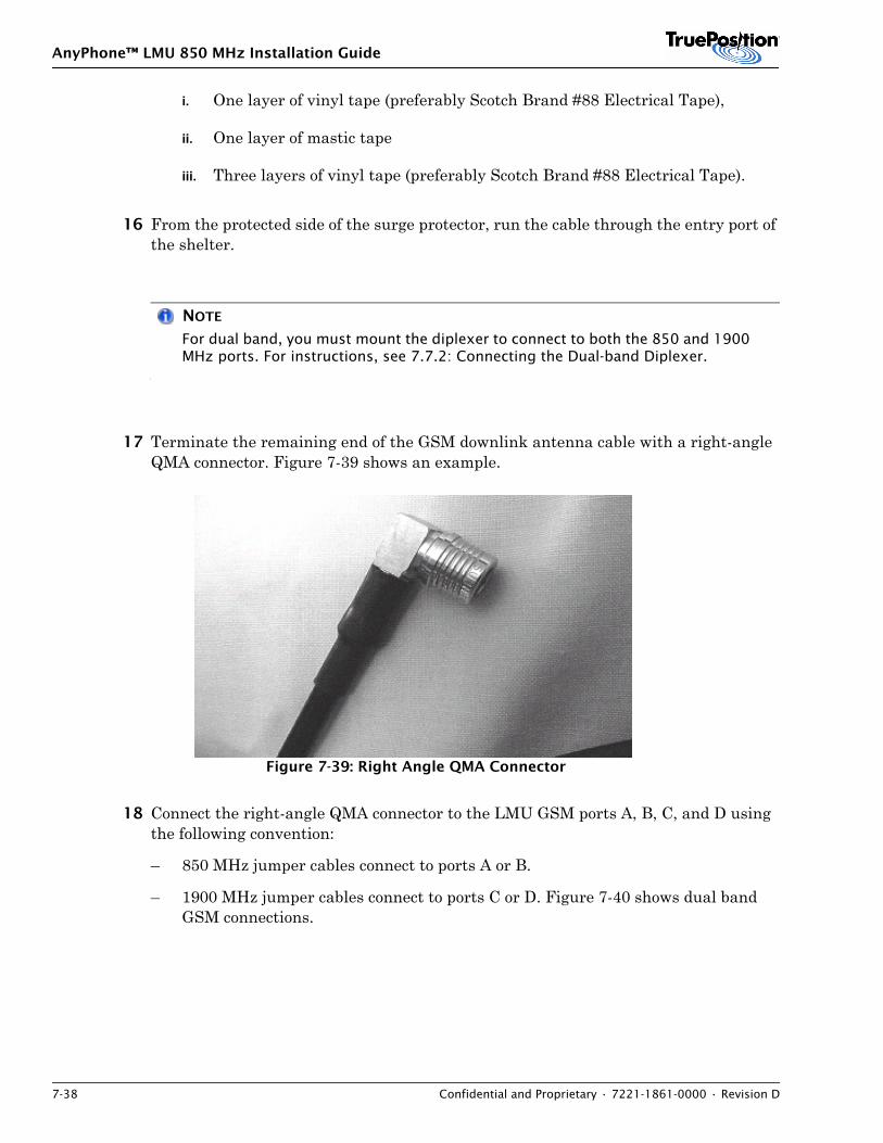
AnyPhone™ LMU 850 MHz Installation Guide
7-38 Confidential and Proprietary • 7221-1861-0000 • Revision D
i. One layer of vinyl tape (preferably Scotch Brand #88 Electrical Tape),
ii. One layer of mastic tape
iii. Three layers of vinyl tape (preferably Scotch Brand #88 Electrical Tape).
16 From the protected side of the surge protector, run the cable through the entry port of the shelter.
NOTE
For dual band, you must mount the diplexer to connect to both the 850 and 1900 MHz ports. For instructions, see 7.7.2: Connecting the Dual-band Diplexer.
17 Terminate the remaining end of the GSM downlink antenna cable with a right-angle QMA connector. Figure 7-39 shows an example.
Figure 7-39: Right Angle QMA Connector
18 Connect the right-angle QMA connector to the LMU GSM ports A, B, C, and D using the following convention:
– 850 MHz jumper cables connect to ports A or B.
– 1900 MHz jumper cables connect to ports C or D. Figure 7-40 shows dual band GSM connections.
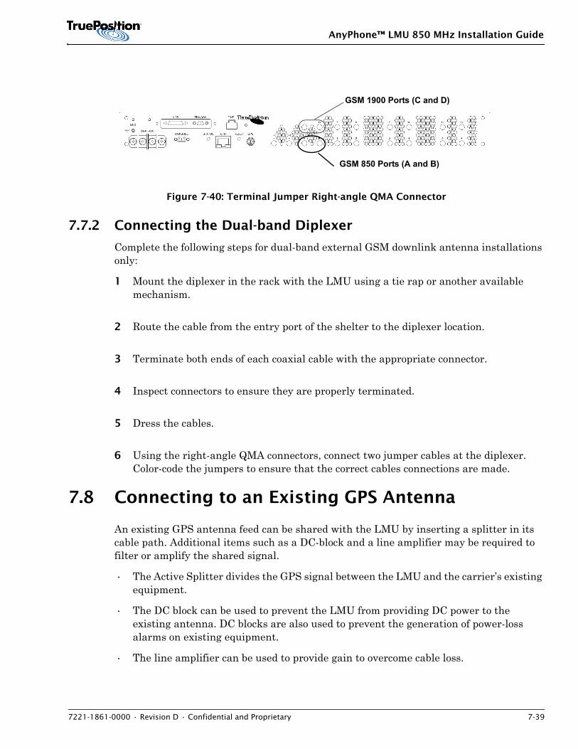
AnyPhone™ LMU 850 MHz Installation Guide
7221-1861-0000 • Revision D • Confidential and Proprietary 7-39
Figure 7-40: Terminal Jumper Right-angle QMA Connector
7.7.2 Connecting the Dual-band Diplexer
Complete the following steps for dual-band external GSM downlink antenna installations only:
1 Mount the diplexer in the rack with the LMU using a tie rap or another available mechanism.
2 Route the cable from the entry port of the shelter to the diplexer location.
3 Terminate both ends of each coaxial cable with the appropriate connector.
4 Inspect connectors to ensure they are properly terminated.
5 Dress the cables.
6 Using the right-angle QMA connectors, connect two jumper cables at the diplexer. Color-code the jumpers to ensure that the correct cables connections are made.
7.8 Connecting to an Existing GPS Antenna
An existing GPS antenna feed can be shared with the LMU by inserting a splitter in its cable path. Additional items such as a DC-block and a line amplifier may be required to filter or amplify the shared signal.
• The Active Splitter divides the GPS signal between the LMU and the carrier’s existing equipment.
• The DC block can be used to prevent the LMU from providing DC power to the existing antenna. DC blocks are also used to prevent the generation of power-loss alarms on existing equipment.
• The line amplifier can be used to provide gain to overcome cable loss.
GSM 850 Ports (A and B)
GSM 1900 Ports (C and D)
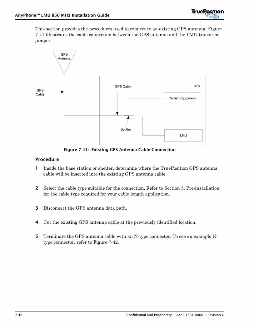
AnyPhone™ LMU 850 MHz Installation Guide
7-40 Confidential and Proprietary • 7221-1861-0000 • Revision D
This section provides the procedures used to connect to an existing GPS antenna. Figure 7-41 illustrates the cable connection between the GPS antenna and the LMU transition jumper.
Figure 7-41: Existing GPS Antenna Cable Connection
Procedure
1 Inside the base station or shelter, determine where the TruePosition GPS antenna cable will be inserted into the existing GPS antenna cable.
2 Select the cable type suitable for the connection. Refer to Section 5, Pre-installation for the cable type required for your cable length application.
3 Disconnect the GPS antenna data path.
4 Cut the existing GPS antenna cable at the previously identified location.
5 Terminate the GPS antenna cable with an N-type connector. To see an example N-type connector, refer to Figure 7-42.
GPSAntenna
LMU
GPSCable
BTSGPS Cable
Carrier Equipment
Splitter
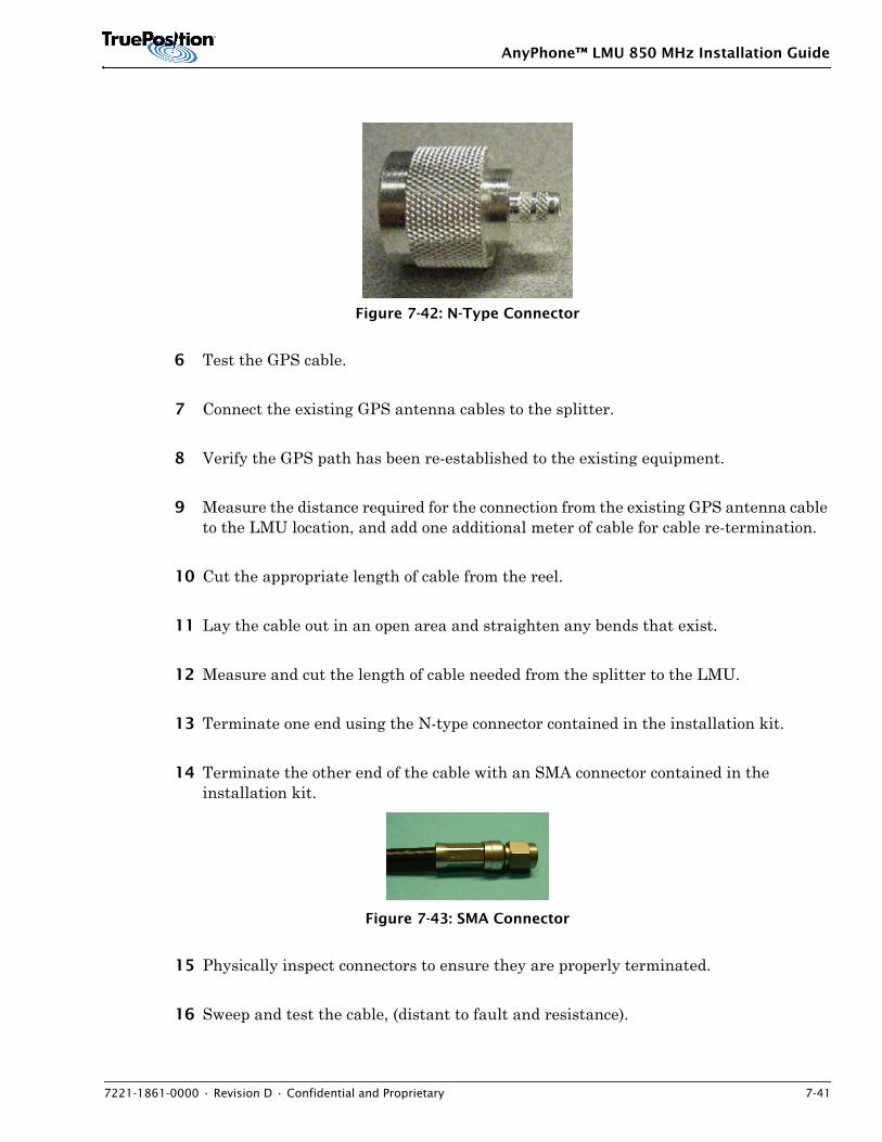
AnyPhone™ LMU 850 MHz Installation Guide
7221-1861-0000 • Revision D • Confidential and Proprietary 7-41
Figure 7-42: N-Type Connector
6 Test the GPS cable.
7 Connect the existing GPS antenna cables to the splitter.
8 Verify the GPS path has been re-established to the existing equipment.
9 Measure the distance required for the connection from the existing GPS antenna cable to the LMU location, and add one additional meter of cable for cable re-termination.
10 Cut the appropriate length of cable from the reel.
11 Lay the cable out in an open area and straighten any bends that exist.
12 Measure and cut the length of cable needed from the splitter to the LMU.
13 Terminate one end using the N-type connector contained in the installation kit.
14 Terminate the other end of the cable with an SMA connector contained in the installation kit.
Figure 7-43: SMA Connector
15 Physically inspect connectors to ensure they are properly terminated.
16 Sweep and test the cable, (distant to fault and resistance).
AnyPhone™ LMU 850 MHz Installation Guide
7-42 Confidential and Proprietary • 7221-1861-0000 • Revision D
17 Route the cable from its source to its destination.
18 If a DC block is required, connect the DC block to the splitter.
19 If the line amplifier is required, connect the line amplifier to the DC block or splitter.
20 Connect the cable to the line amplifier, DC block, or splitter.
21 Route the remaining length of cable from its source to its destination. Using an SMA-torque wrench, secure the GPS jumper connector to the LMU GPS port.
22 Coil the cable leaving enough slack to reach the LMU location, in case of re-termination.
AnyPhone™ LMU 850 MHz Installation Guide
7221-1861-0000 • Revision D • Confidential and Proprietary 8-1
8. CHASSIS INSTALL
Contents8.1 Rack Mounting and Installation . . . . . . . . . . . . . . . . . . . . . . . . . . . . . . . . . . . . . . . . . . . . 8-18.2 Wall Mount Installation . . . . . . . . . . . . . . . . . . . . . . . . . . . . . . . . . . . . . . . . . . . . . . . . . . 8-4
This section provides instructions to mount and install the LMU an equipment rack or wall mount. For LMU mounting constraints, refer to the appropriate Pre-installation section.
The LMU installation kit PL-06-1716-xx applies for single band installation options. For dual band, use two kits.
NOTE
Bring the rack’s contact surface to a bright finish using light wire brush and coat it with an antioxidant before making connections to it.
8.1 Rack Mounting and Installation
There are three options for mounting the LMU:
• Mount and install the LMU in a 19-inch equipment rack.
• Mount and install the LMU in a 23-inch equipment rack.
• Mount and install the 2 rack-unit (2 RU) LMU in a 19-inch equipment rack.
The LMU mounting kits provide mounting flanges with rack mounting holes (refer to Figure 8-1) matched to the front or mid chassis. The mounting holes are spaced so that a combination of holes can be matched up for mounting on the front or mid-chassis.
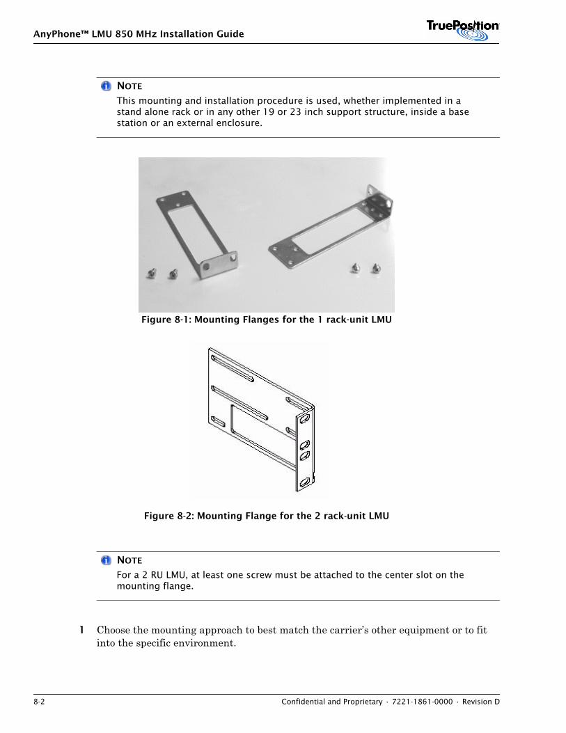
AnyPhone™ LMU 850 MHz Installation Guide
8-2 Confidential and Proprietary • 7221-1861-0000 • Revision D
NOTE
This mounting and installation procedure is used, whether implemented in a stand alone rack or in any other 19 or 23 inch support structure, inside a base station or an external enclosure.
Figure 8-1: Mounting Flanges for the 1 rack-unit LMU
Figure 8-2: Mounting Flange for the 2 rack-unit LMU
NOTE
For a 2 RU LMU, at least one screw must be attached to the center slot on the mounting flange.
1 Choose the mounting approach to best match the carrier’s other equipment or to fit into the specific environment.
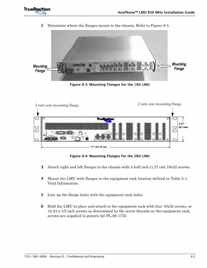
AnyPhone™ LMU 850 MHz Installation Guide
7221-1861-0000 • Revision D • Confidential and Proprietary 8-3
2 Determine where the flanges mount to the chassis. Refer to Figure 8-3.
Figure 8-3: Mounting Flanges for the 1RU LMU
Figure 8-4: Mounting Flanges for the 2RU LMU
3 Attach right and left flanges to the chassis with 4 half inch (1.27 cm) 10x32 screws.
4 Mount the LMU with flanges in the equipment rack location defined in Table 5-1: Vital Information.
5 Line up the flange holes with the equipment rack holes.
6 Hold the LMU in place and attach to the equipment rack with four 10x32 screws, or 12-24 x 1/2 inch screws as determined by the screw threads on the equipment rack, screws are supplied in generic kit PL-06-1732.
2 rack-unit mounting flange 2 rack-unit mounting flange
17" (43.18 CM)
3.47"88.13MM
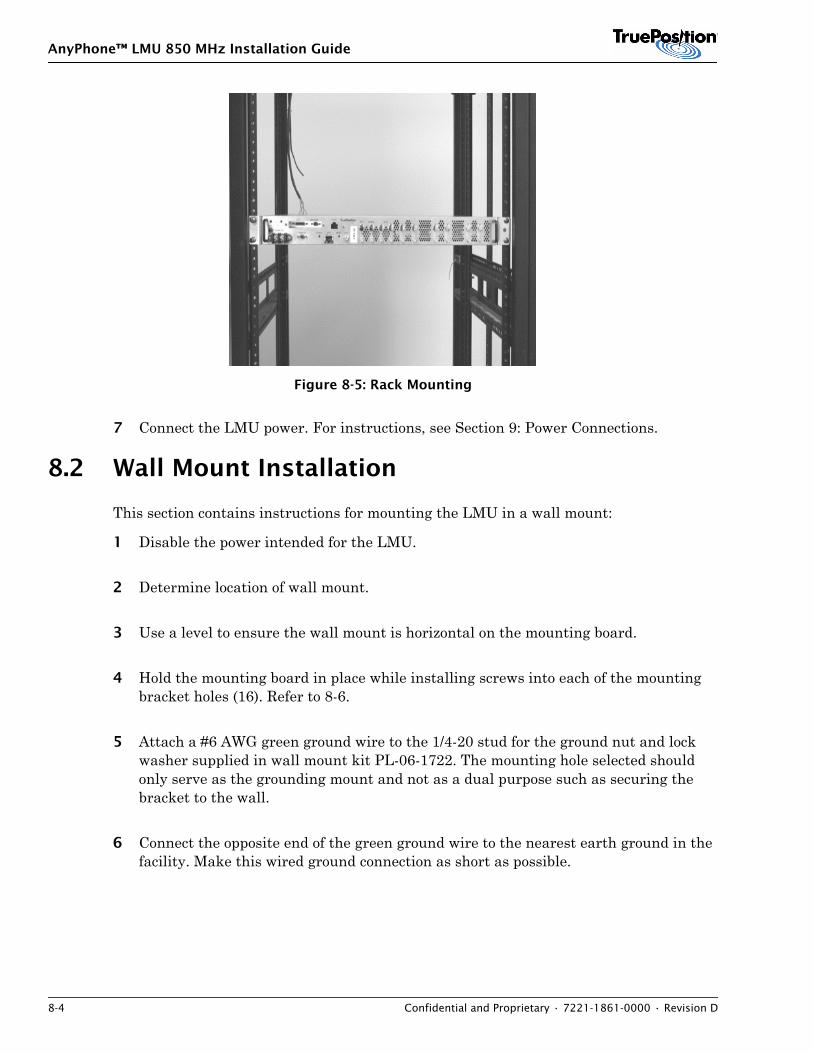
AnyPhone™ LMU 850 MHz Installation Guide
8-4 Confidential and Proprietary • 7221-1861-0000 • Revision D
Figure 8-5: Rack Mounting
7 Connect the LMU power. For instructions, see Section 9: Power Connections.
8.2 Wall Mount Installation
This section contains instructions for mounting the LMU in a wall mount:
1 Disable the power intended for the LMU.
2 Determine location of wall mount.
3 Use a level to ensure the wall mount is horizontal on the mounting board.
4 Hold the mounting board in place while installing screws into each of the mounting bracket holes (16). Refer to 8-6.
5 Attach a #6 AWG green ground wire to the 1/4-20 stud for the ground nut and lock washer supplied in wall mount kit PL-06-1722. The mounting hole selected should only serve as the grounding mount and not as a dual purpose such as securing the bracket to the wall.
6 Connect the opposite end of the green ground wire to the nearest earth ground in the facility. Make this wired ground connection as short as possible.
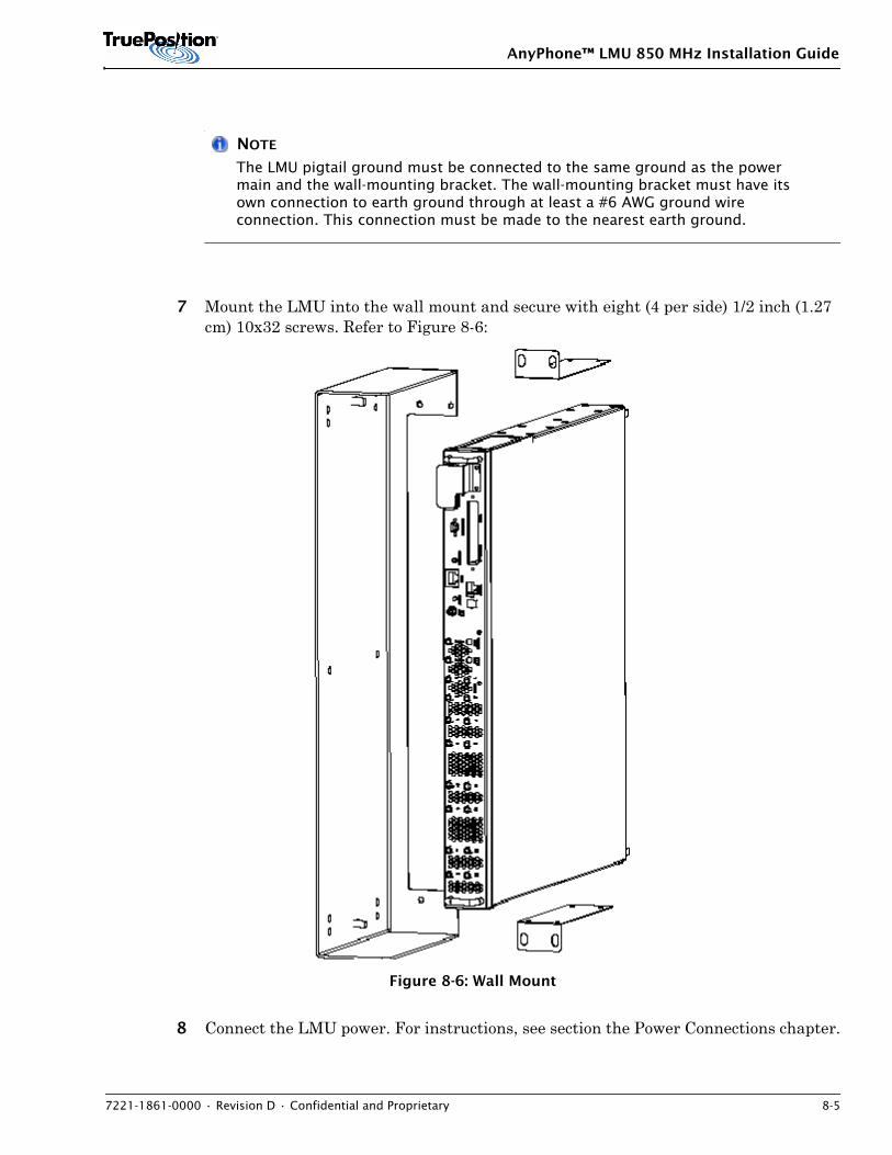
AnyPhone™ LMU 850 MHz Installation Guide
7221-1861-0000 • Revision D • Confidential and Proprietary 8-5
NOTE
The LMU pigtail ground must be connected to the same ground as the power main and the wall-mounting bracket. The wall-mounting bracket must have its own connection to earth ground through at least a #6 AWG ground wire connection. This connection must be made to the nearest earth ground.
7 Mount the LMU into the wall mount and secure with eight (4 per side) 1/2 inch (1.27 cm) 10x32 screws. Refer to Figure 8-6:
Figure 8-6: Wall Mount
8 Connect the LMU power. For instructions, see section the Power Connections chapter.
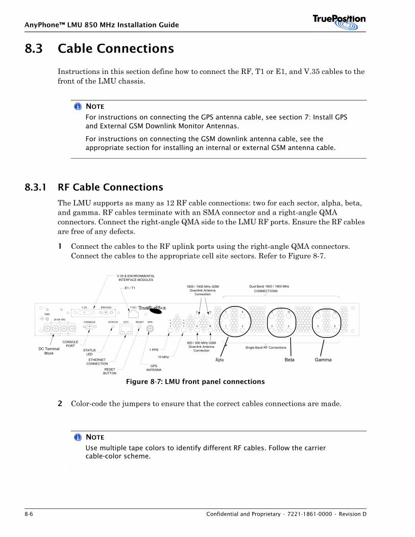
AnyPhone™ LMU 850 MHz Installation Guide
8-6 Confidential and Proprietary • 7221-1861-0000 • Revision D
8.3 Cable Connections
Instructions in this section define how to connect the RF, T1 or E1, and V.35 cables to the front of the LMU chassis.
NOTE
For instructions on connecting the GPS antenna cable, see section 7: Install GPS and External GSM Downlink Monitor Antennas.
For instructions on connecting the GSM downlink antenna cable, see the appropriate section for installing an internal or external GSM antenna cable.
8.3.1 RF Cable Connections
The LMU supports as many as 12 RF cable connections: two for each sector, alpha, beta, and gamma. RF cables terminate with an SMA connector and a right-angle QMA connectors. Connect the right-angle QMA side to the LMU RF ports. Ensure the RF cables are free of any defects.
1 Connect the cables to the RF uplink ports using the right-angle QMA connectors. Connect the cables to the appropriate cell site sectors. Refer to Figure 8-7.
Figure 8-7: LMU front panel connections
2 Color-code the jumpers to ensure that the correct cables connections are made.
NOTE
Use multiple tape colors to identify different RF cables. Follow the carrier cable-color scheme.
Alpha Beta Gamma
12111098D 7C
BA 21 3 54 6
STATUSLED
Single Band RF Connections1 PPS
10 MHz
CONSOLEPORT
ETHERNETCONNECTION
V.35 & ENVIRONMENTALINTERFACE MODULES
CONNECTIONS
GPSANTENNARESET
BUTTON
24-48 VDCCONSOLE STATUS RESETETH GPS
V.35
GND
ENV/AOA T1/E1
850 / 900 MHz GSMDownlink Antenna
Connection
1800 / 1900 MHz GSMDownlink Antenna
Connection
DC TerminalBlock
Dual Band 1800 / 1900 MHzE1 / T1
Alpha Beta Gamma
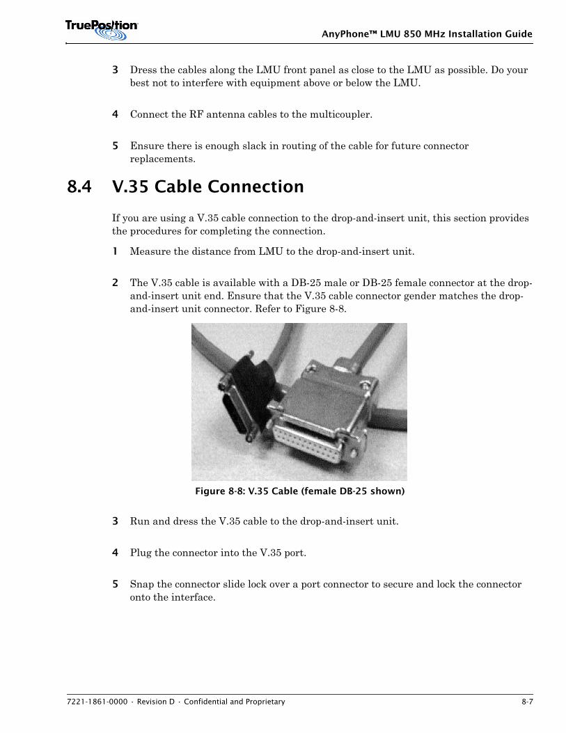
AnyPhone™ LMU 850 MHz Installation Guide
7221-1861-0000 • Revision D • Confidential and Proprietary 8-7
3 Dress the cables along the LMU front panel as close to the LMU as possible. Do your best not to interfere with equipment above or below the LMU.
4 Connect the RF antenna cables to the multicoupler.
5 Ensure there is enough slack in routing of the cable for future connector replacements.
8.4 V.35 Cable Connection
If you are using a V.35 cable connection to the drop-and-insert unit, this section provides the procedures for completing the connection.
1 Measure the distance from LMU to the drop-and-insert unit.
2 The V.35 cable is available with a DB-25 male or DB-25 female connector at the drop-and-insert unit end. Ensure that the V.35 cable connector gender matches the drop-and-insert unit connector. Refer to Figure 8-8.
Figure 8-8: V.35 Cable (female DB-25 shown)
3 Run and dress the V.35 cable to the drop-and-insert unit.
4 Plug the connector into the V.35 port.
5 Snap the connector slide lock over a port connector to secure and lock the connector onto the interface.
AnyPhone™ LMU 850 MHz Installation Guide
8-8 Confidential and Proprietary • 7221-1861-0000 • Revision D
8.5 T1 Cable Connection
If you are using a T1 cable connection to the drop-and-insert unit, this section provides the procedures for completing the connection.
1 Measure the distance from LMU to the drop-and-insert unit.
2 Confirm that pin out assignments of the T1 crossover cable are matched. Use an ohmmeter to test continuity on both ends of the cable. To see the pinout convention used for the T1 crossover cable, see section 5.4 Selecting Cables.
3 Run, terminate, and dress the shielded CAT-5 T1 cable to the drop-and-insert unit.
4 Plug the connector into the T1 port.
Continue the installation with the Power Connections chapters.
8.6 E1 Cable Connection
If you are using a E1 cable connection to the drop-and-insert unit, this section provides the procedures for completing the connection.
1 Measure the distance from LMU to the drop-and-insert unit.
2 Confirm that pin out assignments of the E1 crossover cable are matched. Use an ohmmeter to test continuity on both ends of the cable. To see the pinout convention used for the E1 crossover cable, see section 5.4 Selecting Cables.
!CAUTION
Do not connect a V.35 and a T1 at the same time. The LMU does not support simultaneous V.35 and T1 operation.
!CAUTION
Do not connect a V.35 and a E1 at the same time. The LMU does not support simultaneous V.35 and E1 operation.
AnyPhone™ LMU 850 MHz Installation Guide
7221-1861-0000 • Revision D • Confidential and Proprietary 8-9
3 Run, terminate, and dress the E1 cable to the drop-and-insert unit.
4 Plug the connector into the E1 port.
Continue the installation with the Power Connections chapter.

AnyPhone™ LMU 850 MHz Installation Guide
8-10 Confidential and Proprietary • 7221-1861-0000 • Revision D
AnyPhone™ LMU 850 MHz Installation Guide
7221-1861-0000 • Revision D • Confidential and Proprietary 9-1
9. POWER CONNECTIONS
Contents9.1 Ground and Power Cable Connection . . . . . . . . . . . . . . . . . . . . . . . . . . . . . . . . . . . . . . . . 9-19.2 Power the LMU . . . . . . . . . . . . . . . . . . . . . . . . . . . . . . . . . . . . . . . . . . . . . . . . . . . . . . . . 9-3
This section provides procedures for pulling, terminating, dressing, and installing power cable connectors to the LMU.
9.1 Ground and Power Cable Connection
1 Use a voltmeter to determine whether the DC power serial port on the BTS is receiving power.
2 Select the three position power pigtail cable from the LMU install kit, (part number AD-06-1230-00). Figure 9-1 shows an example.
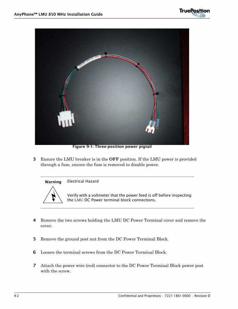
AnyPhone™ LMU 850 MHz Installation Guide
9-2 Confidential and Proprietary • 7221-1861-0000 • Revision D
Figure 9-1: Three-position power pigtail
3 Ensure the LMU breaker is in the OFF position. If the LMU power is provided through a fuse, ensure the fuse is removed to disable power.
4 Remove the two screws holding the LMU DC Power Terminal cover and remove the cover.
5 Remove the ground post nut from the DC Power Terminal Block.
6 Loosen the terminal screws from the DC Power Terminal Block.
7 Attach the power wire (red) connector to the DC Power Terminal Block power post with the screw.
Warning Electrical Hazard
Verify with a voltmeter that the power feed is off before inspecting the LMU DC Power terminal block connections.
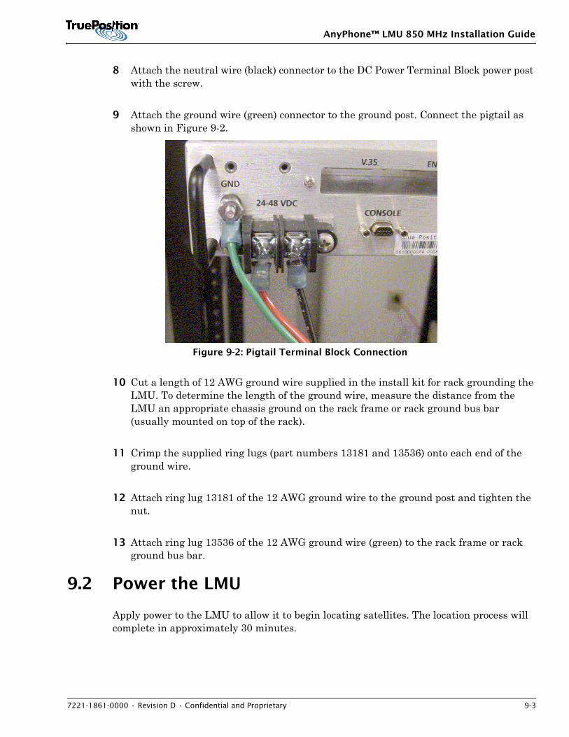
AnyPhone™ LMU 850 MHz Installation Guide
7221-1861-0000 • Revision D • Confidential and Proprietary 9-3
8 Attach the neutral wire (black) connector to the DC Power Terminal Block power post with the screw.
9 Attach the ground wire (green) connector to the ground post. Connect the pigtail as shown in Figure 9-2.
Figure 9-2: Pigtail Terminal Block Connection
10 Cut a length of 12 AWG ground wire supplied in the install kit for rack grounding the LMU. To determine the length of the ground wire, measure the distance from the LMU an appropriate chassis ground on the rack frame or rack ground bus bar (usually mounted on top of the rack).
11 Crimp the supplied ring lugs (part numbers 13181 and 13536) onto each end of the ground wire.
12 Attach ring lug 13181 of the 12 AWG ground wire to the ground post and tighten the nut.
13 Attach ring lug 13536 of the 12 AWG ground wire (green) to the rack frame or rack ground bus bar.
9.2 Power the LMU
Apply power to the LMU to allow it to begin locating satellites. The location process will complete in approximately 30 minutes.
AnyPhone™ LMU 850 MHz Installation Guide
9-4 Confidential and Proprietary • 7221-1861-0000 • Revision D
NOTE
The previous sections must be completed before powering the LMU.
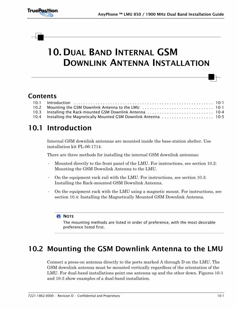
AnyPhone ™ LMU 850 / 1900 MHz Dual Band Installation Guide
7221-1862-0000 • Revision D • Confidential and Proprietary 10-1
10. DUAL BAND INTERNAL GSM DOWNLINK ANTENNA INSTALLATION
Contents10.1 Introduction . . . . . . . . . . . . . . . . . . . . . . . . . . . . . . . . . . . . . . . . . . . . . . . . . . . . . . . . . 10-110.2 Mounting the GSM Downlink Antenna to the LMU . . . . . . . . . . . . . . . . . . . . . . . . . . . . . 10-110.3 Installing the Rack-mounted GSM Downlink Antenna . . . . . . . . . . . . . . . . . . . . . . . . . . . 10-410.4 Installing the Magnetically Mounted GSM Downlink Antenna . . . . . . . . . . . . . . . . . . . . . 10-5
10.1 Introduction
Internal GSM downlink antennas are mounted inside the base-station shelter. Use installation kit PL-06-1714.
There are three methods for installing the internal GSM downlink antennas:
• Mounted directly to the front panel of the LMU. For instructions, see section 10.2: Mounting the GSM Downlink Antenna to the LMU.
• On the equipment rack rail with the LMU. For instructions, see section 10.3: Installing the Rack-mounted GSM Downlink Antenna.
• On the equipment rack with the LMU using a magnetic mount. For instructions, see section 10.4: Installing the Magnetically Mounted GSM Downlink Antenna.
NOTE
The mounting methods are listed in order of preference, with the most desirable preference listed first.
10.2 Mounting the GSM Downlink Antenna to the LMU
Connect a press-on antenna directly to the ports marked A through D on the LMU. The GSM downlink antenna must be mounted vertically regardless of the orientation of the LMU. For dual-band installations point one antenna up and the other down. Figures 10-1 and 10-3 show examples of a dual-band installation.
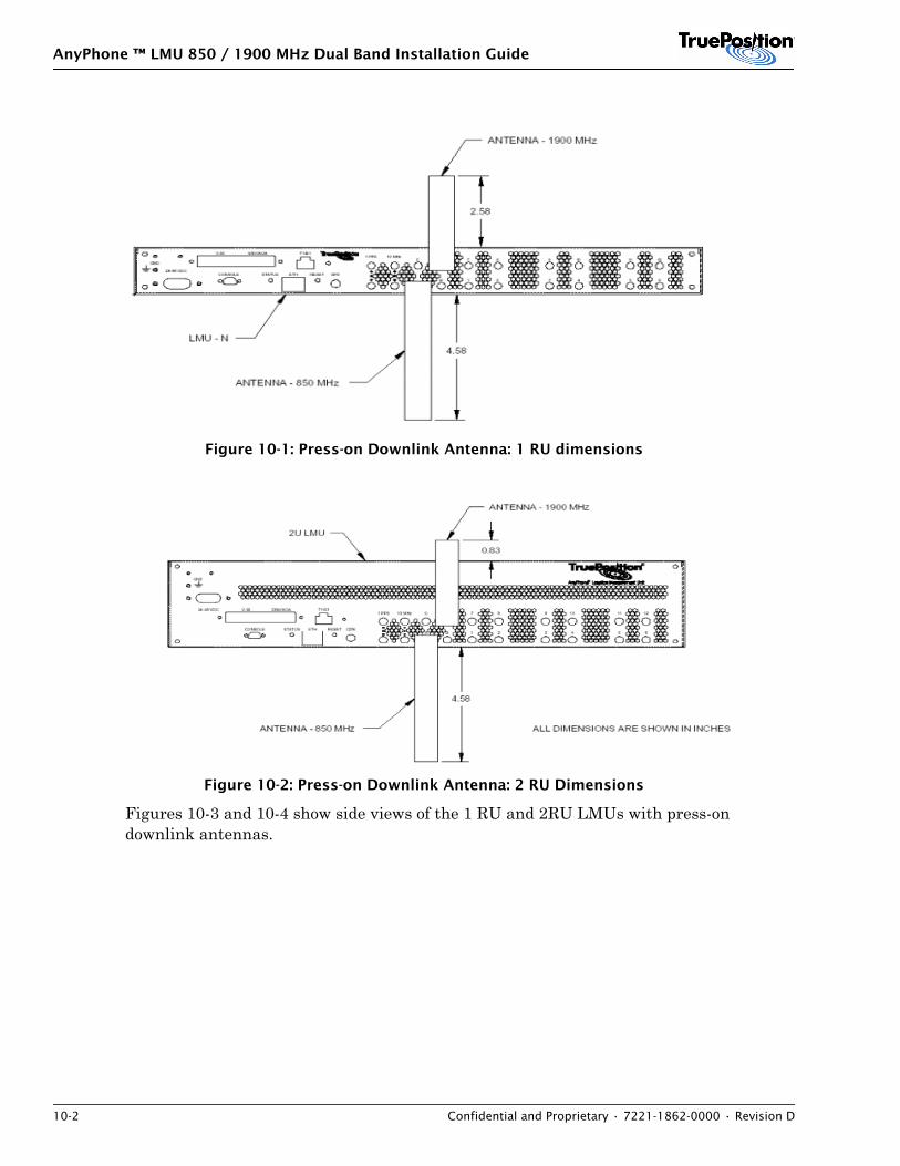
AnyPhone ™ LMU 850 / 1900 MHz Dual Band Installation Guide
10-2 Confidential and Proprietary • 7221-1862-0000 • Revision D
Figure 10-1: Press-on Downlink Antenna: 1 RU dimensions
Figure 10-2: Press-on Downlink Antenna: 2 RU Dimensions
Figures 10-3 and 10-4 show side views of the 1 RU and 2RU LMUs with press-on downlink antennas.
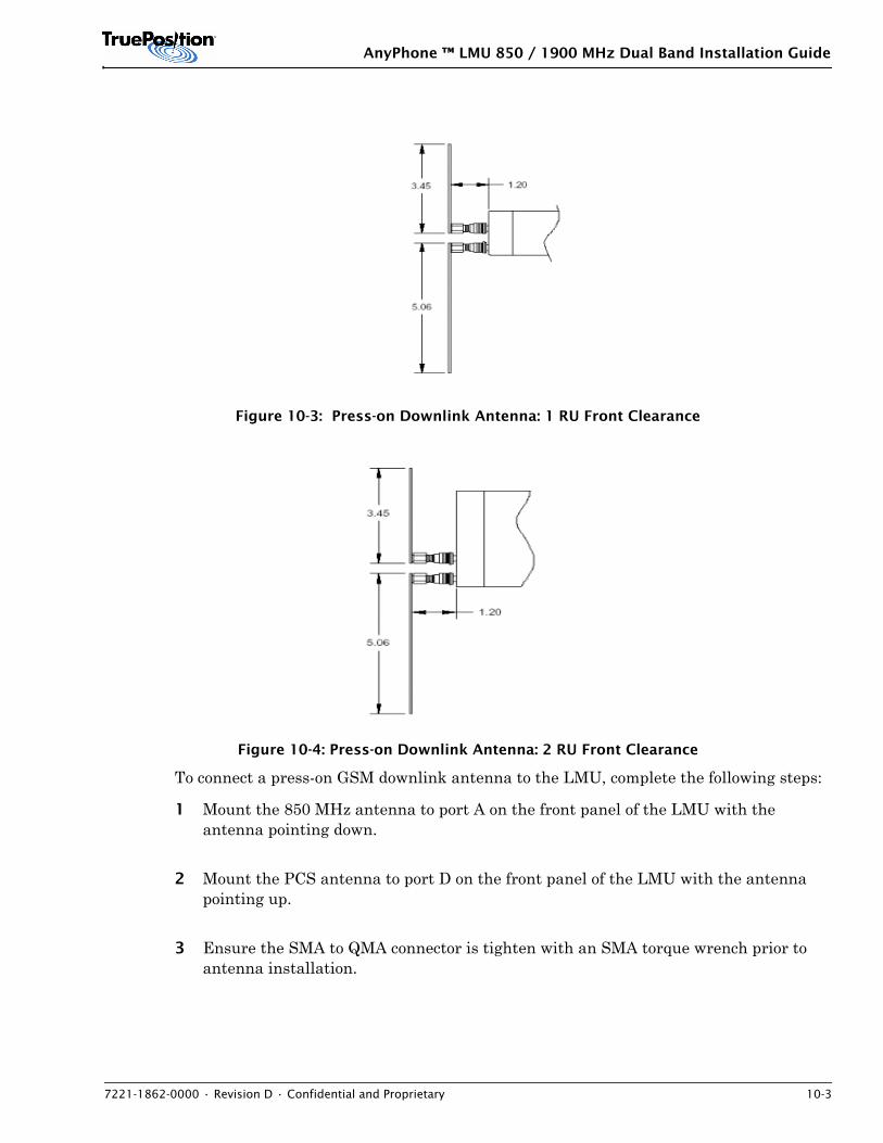
AnyPhone ™ LMU 850 / 1900 MHz Dual Band Installation Guide
7221-1862-0000 • Revision D • Confidential and Proprietary 10-3
Figure 10-3: Press-on Downlink Antenna: 1 RU Front Clearance
Figure 10-4: Press-on Downlink Antenna: 2 RU Front Clearance
To connect a press-on GSM downlink antenna to the LMU, complete the following steps:
1 Mount the 850 MHz antenna to port A on the front panel of the LMU with the antenna pointing down.
2 Mount the PCS antenna to port D on the front panel of the LMU with the antenna pointing up.
3 Ensure the SMA to QMA connector is tighten with an SMA torque wrench prior to antenna installation.
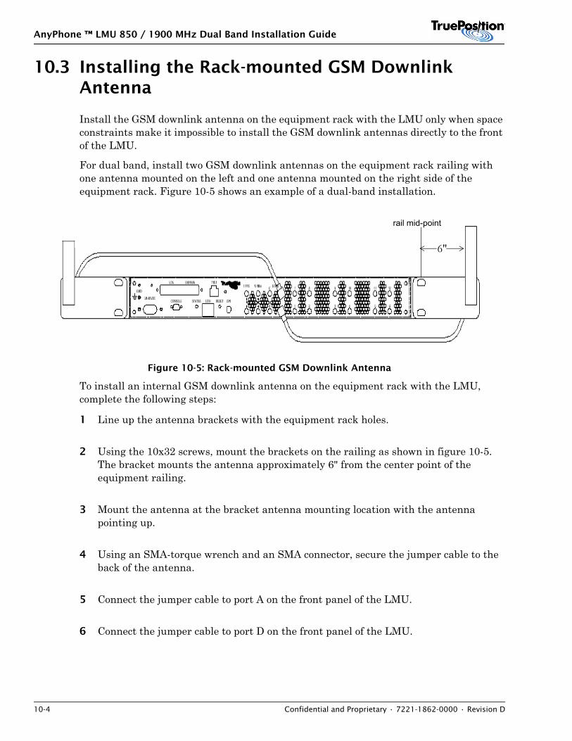
AnyPhone ™ LMU 850 / 1900 MHz Dual Band Installation Guide
10-4 Confidential and Proprietary • 7221-1862-0000 • Revision D
10.3 Installing the Rack-mounted GSM Downlink Antenna
Install the GSM downlink antenna on the equipment rack with the LMU only when space constraints make it impossible to install the GSM downlink antennas directly to the front of the LMU.
For dual band, install two GSM downlink antennas on the equipment rack railing with one antenna mounted on the left and one antenna mounted on the right side of the equipment rack. Figure 10-5 shows an example of a dual-band installation.
Figure 10-5: Rack-mounted GSM Downlink Antenna
To install an internal GSM downlink antenna on the equipment rack with the LMU, complete the following steps:
1 Line up the antenna brackets with the equipment rack holes.
2 Using the 10x32 screws, mount the brackets on the railing as shown in figure 10-5. The bracket mounts the antenna approximately 6" from the center point of the equipment railing.
3 Mount the antenna at the bracket antenna mounting location with the antenna pointing up.
4 Using an SMA-torque wrench and an SMA connector, secure the jumper cable to the back of the antenna.
5 Connect the jumper cable to port A on the front panel of the LMU.
6 Connect the jumper cable to port D on the front panel of the LMU.
6"
rail mid-point
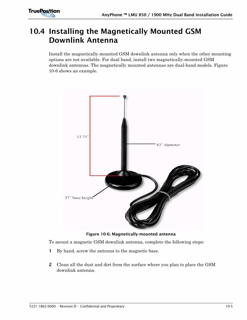
AnyPhone ™ LMU 850 / 1900 MHz Dual Band Installation Guide
7221-1862-0000 • Revision D • Confidential and Proprietary 10-5
10.4 Installing the Magnetically Mounted GSM Downlink Antenna
Install the magnetically-mounted GSM downlink antenna only when the other mounting options are not available. For dual band, install two magnetically-mounted GSM downlink antennas. The magnetically mounted antennas are dual-band models. Figure 10-6 shows an example.
Figure 10-6: Magnetically-mounted antenna
To mount a magnetic GSM downlink antenna, complete the following steps:
1 By hand, screw the antenna to the magnetic base.
2 Clean all the dust and dirt from the surface where you plan to place the GSM downlink antenna.
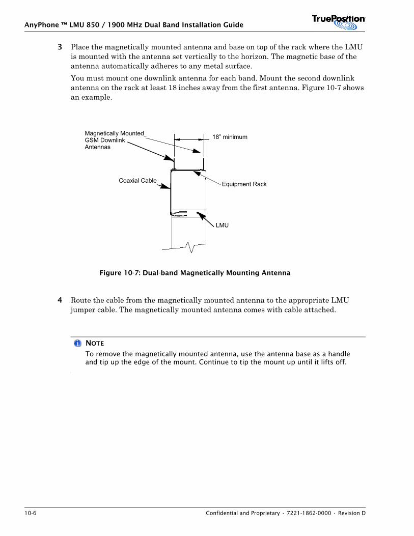
AnyPhone ™ LMU 850 / 1900 MHz Dual Band Installation Guide
10-6 Confidential and Proprietary • 7221-1862-0000 • Revision D
3 Place the magnetically mounted antenna and base on top of the rack where the LMU is mounted with the antenna set vertically to the horizon. The magnetic base of the antenna automatically adheres to any metal surface.You must mount one downlink antenna for each band. Mount the second downlink antenna on the rack at least 18 inches away from the first antenna. Figure 10-7 shows an example.
Figure 10-7: Dual-band Magnetically Mounting Antenna
4 Route the cable from the magnetically mounted antenna to the appropriate LMU jumper cable. The magnetically mounted antenna comes with cable attached.
NOTE
To remove the magnetically mounted antenna, use the antenna base as a handle and tip up the edge of the mount. Continue to tip the mount up until it lifts off.
Magnetically MountedGSM DownlinkAntennas
18” minimum
LMU
Coaxial Cable Equipment Rack
AnyPhone™ LMU 850 MHz Installation Guide
7221-1861-0000 • Revision D • Confidential and Proprietary 11-1
11. CONFIGURATION AND TEST OVERVIEW
Contents11.1 Preparation . . . . . . . . . . . . . . . . . . . . . . . . . . . . . . . . . . . . . . . . . . . . . . . . . . . . . . . . . . 11-1
The following sections define how to configure and test an Anyphone LMU for operation.
Perform the procedures using the connection from the LMU console port to the laptop computer. You must configure ProComm Plus for communicating with the LMU. For instructions, see Appendix A.2: Configuring the Console Interface. After completing configuration and system testing, the LMU is ready for operation.
Configuration includes the following:
• Set T1 / E1, and V.35 strappingEnabling one of the LMU T1 DS0 time slots.
• Set GPS parametersSetting and checking GPS location parameters.
• Check RF gainConduct the built-in test (BIT) 6. The BIT 6 measures the power spectral data received from the six LMU RF antennas.
• Test the digital signal processor (DSP) MemoryUse BIT 4 to check the operation of the four LMU DSP memory modules.
• Test the Central Processor (CP) MemoryUse BIT 5 to check the operation of the CP memory module.
• Test the GSM downlink antenna. This applies for GSM installations only.
NOTE
This procedure is compatible with LMU FLASH release -R7.0BL025 and higher.
11.1 Preparation
Complete the preparation and installation procedures in this guide before configuring and testing the LMU.

AnyPhone™ LMU 850 MHz Installation Guide
11-2 Confidential and Proprietary • 7221-1861-0000 • Revision D
AnyPhone™ LMU 850 MHz Installation Guide
7221-1861-0000 • Revision D • Confidential and Proprietary 12-1
12. SETTING UP THE PROCOMM CONSOLE INTERFACE
Contents12.1 The ProComm Chat Window . . . . . . . . . . . . . . . . . . . . . . . . . . . . . . . . . . . . . . . . . . . . . 12-112.2 Standard Operating Mode . . . . . . . . . . . . . . . . . . . . . . . . . . . . . . . . . . . . . . . . . . . . . . . 12-212.3 Operating Following A Reset . . . . . . . . . . . . . . . . . . . . . . . . . . . . . . . . . . . . . . . . . . . . . 12-2
In order to perform LMU configuration and testing, you must set up the ProComm console terminal along with a Chat Window on your laptop. To set up the ProComm terminal emulation program for communicating with the LMU, complete the following steps:
1 Connect the laptop to the LMU console port use the Cable Assembly DB9 Interface 72.00 inch Adapter, part number AD-06-1113-00.
2 Open the ProComm application on the laptop.
3 Set the ProComm parameters to 115.2K, N-8-1, Raw ANSI and VT-100.
4 R to display a prompt
5 Select the Comm Port number being used in the Pro Com terminal window.
6 Click Data and then click Chat Window.
12.1 The ProComm Chat Window
Use the ProComm Chat window to enter commands when testing and configuring an LMU. Type all console port commands in the ProComm Chat window, with the LMU in standard operating mode.
AnyPhone™ LMU 850 MHz Installation Guide
12-2 Confidential and Proprietary • 7221-1861-0000 • Revision D
NOTE
You must close the Procomm application before disconnecting the console cable.
12.2 Standard Operating Mode
To operate the LMU using the ProComm Chat Window, you must be in Standard mode. The LMU automatically boots in standard mode if it is receiving GPS and T1 /E1/V.35 signals. Standard mode is defined as:
• The default mode
• Displays the LMU> prompt
• Is used for all commands described in this section
• Is also referred to as the dshell
• Is not case sensitive when used with the ProComm Chat window
If the LMU does not have a T1 /E1 or V.35 connection and/or Gps locked (i.e., No GPS connection) following a power up or reset, the start up process stops from automatically placing the LMU into the standard operating mode.
This is a common condition at installation time, since LMUs are not configured for the proper interface modes and strapping. These conditions can be confirmed by R and observing the LMU prompt.
1 If the prompt is BOOT>, then the LMU does not have the proper T1/E1/V.35 connections/signals.
2 If the prompt is --->, then the LMU has the proper T1/E1/V.35 connections/signals, but if does have a condition, such as “no GPS signal lock”.
Section 12.3: Operating Following A Reset instructs the operator how to manually command the LMU into Standard Operating Mode so it can be configured and tested.
12.3 Operating Following A Reset
This section describes how to operate the LMU following a reset.
12.3.1 Reset without a T1/E1/V.35 Signal
This section provides instructions for resetting the LMU when it does not have a T1 / E1/V.35 connection. You need to reset the LMU with the T1 / E1/V.35 port disconnected when configuring the T1 DS0 assignment described in Section 13: Set Up Strapping.
AnyPhone™ LMU 850 MHz Installation Guide
7221-1861-0000 • Revision D • Confidential and Proprietary 12-3
NOTE
The LMU boot process stops after a reset if a T1 / E1/V.35 connection is not established. This condition can also occur if the T1 / E1/V.35 connection is lost between the LMU and the SMLC due to problems in the T1 / E1/V.35 facility.
1 Type reset R.Wait two seconds for the LMU terminal display to stabilize following the reset condition.
2 Confirm that the LMU is in boot state via the BOOT> or LMUBOOT> and then type proc R to allow the LMU to proceed with its startup process. The proc command is not visible on the terminal screen after you type it.
3 If there is an abnormal condition, such as No GPS Signal the LMU proceeds to the Tshell state. The LMU stops displaying messages after the last ESN is displayed and then displays the ---> prompt.
• R to display the prompt. If this is the case, skip the next step and go to Section 12.3.2: Reset without a GPS Signal.
4 If there is no abnormal conditions exists, such as no GPS signal, the LMU completes the startup procedure and displays startup information similar to the following:BootRom Built From: /devvob/LMU-N/CP: element * CHECKEDOUT;element /devvob/releaseCandidate/LMU/...
Built By: ssmith On: Mon Nov 22 14:09:56 EST 2004
BuildTag: LMUFLASH-R9.1BL.1BL060
Application Built From: /devvob/LMU-N/CP: element * CHECKEDOUT;element /devvob/releaseCandidate/LMU/...
Built By: ssmith On: Mon Nov 22 14:09:56 EST 2004
BuildTag: LMUFLASH-R9.1BL060
FPGA version is 102
GPS SW version is TPGPSFLASH-R8.0BL004
GPS FPGA version is TPGPSFPGA-R8.0BL11
GPS ENGINE version is GPS Engine 0.4850266.0.1
AnyPhone™ LMU 850 MHz Installation Guide
12-4 Confidential and Proprietary • 7221-1861-0000 • Revision D
GBE Not ConfiguredLMU>
12.3.2 Reset without a GPS Signal
If the GPS signal is not received during a reset, the LMU boots directly into target shell (tshell),after the PROC edit, R, command of the previous section. The LMU stops displaying message after the last ESN is displayed and then displays the ---> prompt.
1 Confirm the LMU is in Tshell by R and observe the --> prompt.
2 If the LMU is in Tshell, after the PROC,(--->) type dshell R then in the Pro Comm Chat window R to proceed into the Standard Operating Mode.
3 LMU displays the LMU> prompt that it is in the Standard Operating Mode.
4 Standard Operating Mode commands can now be sent to the LMU> prompt. Typing build R returns all the LMU and ancillary equipment builds. LMU displays information similar to the following:BootRom Build From: /devvob/LMU-N/CP: element *CHECKOUT: element /devvob/release Candidate/LMU/...
Build By: jhandel On:Feb 15 11:28:15 EST 2005
Build Tag:LMUBOOT-R9-BL007
ApplicatioN Build fROM:/devvob/LMU-N/CP: element *CHECKOUT: element /devvob/release Candidate/LMU/...
Built By: ssmith On: Wed May 18 15:38:49 EDT 2005
BuildTag: LMUFLASH-R9.1BL133
FPGA version is: LMUFPGA-R6.0BL14 (see note) R. GPS SW version is TPGPSFLASH-R9.1BL010
GPS FPGA version is TPGPSFPGA-R7.0BL11
GPS ENGINE version is GPS Engine 0.4850266.0.2
GBE not configured
LMU>

AnyPhone™ LMU 850 MHz Installation Guide
7221-1861-0000 • Revision D • Confidential and Proprietary 12-5
5

AnyPhone™ LMU 850 MHz Installation Guide
12-6 Confidential and Proprietary • 7221-1861-0000 • Revision D
AnyPhone™ LMU 850 MHz Installation Guide
7221-1861-0000 • Revision D • Confidential and Proprietary 13-1
13. SET UP STRAPPING
Contents13.1 Set the T1 Strapping . . . . . . . . . . . . . . . . . . . . . . . . . . . . . . . . . . . . . . . . . . . . . . . . . . . 13-113.2 Set V.35 Parameters . . . . . . . . . . . . . . . . . . . . . . . . . . . . . . . . . . . . . . . . . . . . . . . . . . . 13-313.3 Set E1 Connection . . . . . . . . . . . . . . . . . . . . . . . . . . . . . . . . . . . . . . . . . . . . . . . . . . . . . 13-513.4 Verify the SMLC Connection . . . . . . . . . . . . . . . . . . . . . . . . . . . . . . . . . . . . . . . . . . . . . . 13-7
Strapping configures the LMU to communicate using T1, E1, or V.35. To set the strapping for the LMU, complete only the appropriate sections for T1, E1 or V.35 below.
NOTE
When entering console port commands, type one space between a command and its variables, and between each variable following the command.
Perform all commands at the LMU> prompt. If you are not at the LMU> prompt, see A: Console Port User Guide for instructions.
13.1 Set the T1 Strapping
To set T1 strapping, complete the following steps:
1 Disconnect the T1 cable from the T1 port on the LMU front panel.
2 Access the LMU using the Console Port connection. For instructions about configuring ProComm Plus, see Section A.2: Configuring the Console Interface.
3 Clear all DS0 bits prior to setting strapping, (clrds0bits command)
4 Type SETNETWORKTYPE 0 R
5 Type strap <DS0 time slot> <network type><speed><framing><line coding> R.
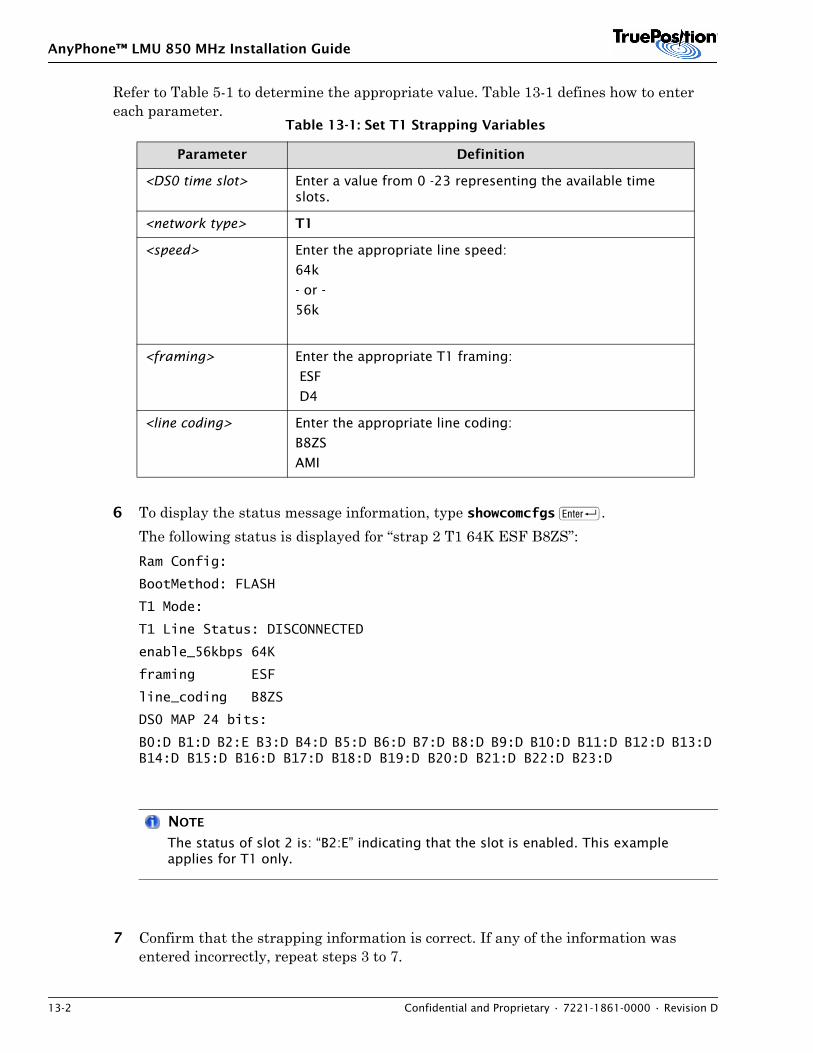
AnyPhone™ LMU 850 MHz Installation Guide
13-2 Confidential and Proprietary • 7221-1861-0000 • Revision D
Refer to Table 5-1 to determine the appropriate value. Table 13-1 defines how to enter each parameter.
6 To display the status message information, type showcomcfgs R.The following status is displayed for “strap 2 T1 64K ESF B8ZS”:Ram Config:
BootMethod: FLASH
T1 Mode:
T1 Line Status: DISCONNECTED
enable_56kbps 64K
framing ESF
line_coding B8ZS
DS0 MAP 24 bits:
B0:D B1:D B2:E B3:D B4:D B5:D B6:D B7:D B8:D B9:D B10:D B11:D B12:D B13:D B14:D B15:D B16:D B17:D B18:D B19:D B20:D B21:D B22:D B23:D
NOTE
The status of slot 2 is: “B2:E” indicating that the slot is enabled. This example applies for T1 only.
7 Confirm that the strapping information is correct. If any of the information was entered incorrectly, repeat steps 3 to 7.
Table 13-1: Set T1 Strapping Variables
Parameter Definition
<DS0 time slot> Enter a value from 0 -23 representing the available time slots.
<network type> T1
<speed> Enter the appropriate line speed:
64k
- or -
56k
<framing> Enter the appropriate T1 framing:
ESF
D4
<line coding> Enter the appropriate line coding:
B8ZS
AMI
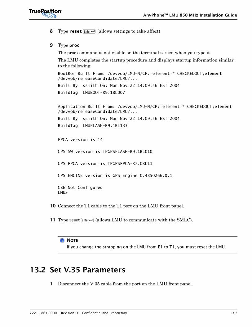
AnyPhone™ LMU 850 MHz Installation Guide
7221-1861-0000 • Revision D • Confidential and Proprietary 13-3
8 Type reset R (allows settings to take affect)
9 Type proc The proc command is not visible on the terminal screen when you type it. The LMU completes the startup procedure and displays startup information similar to the following:BootRom Built From: /devvob/LMU-N/CP: element * CHECKEDOUT;element /devvob/releaseCandidate/LMU/...
Built By: ssmith On: Mon Nov 22 14:09:56 EST 2004
BuildTag: LMUBOOT-R9.1BL007
Application Built From: /devvob/LMU-N/CP: element * CHECKEDOUT;element /devvob/releaseCandidate/LMU/...
Built By: ssmith On: Mon Nov 22 14:09:56 EST 2004
BuildTag: LMUFLASH-R9.1BL133
FPGA version is 14
GPS SW version is TPGPSFLASH-R9.1BL010
GPS FPGA version is TPGPSFPGA-R7.0BL11
GPS ENGINE version is GPS Engine 0.4850266.0.1
GBE Not ConfiguredLMU>
10 Connect the T1 cable to the T1 port on the LMU front panel.
11 Type reset R (allows LMU to communicate with the SMLC).
NOTE
If you change the strapping on the LMU from E1 to T1, you must reset the LMU.
13.2 Set V.35 Parameters
1 Disconnect the V.35 cable from the port on the LMU front panel.
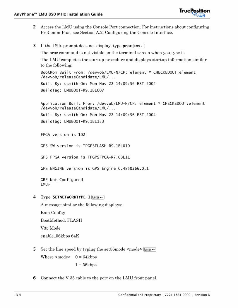
AnyPhone™ LMU 850 MHz Installation Guide
13-4 Confidential and Proprietary • 7221-1861-0000 • Revision D
2 Access the LMU using the Console Port connection. For instructions about configuring ProComm Plus, see Section A.2: Configuring the Console Interface.
3 If the LMU> prompt does not display, type proc R The proc command is not visible on the terminal screen when you type it. The LMU completes the startup procedure and displays startup information similar to the following:BootRom Built From: /devvob/LMU-N/CP: element * CHECKEDOUT;element /devvob/releaseCandidate/LMU/...
Built By: ssmith On: Mon Nov 22 14:09:56 EST 2004
BuildTag: LMUBOOT-R9.1BL007
Application Built From: /devvob/LMU-N/CP: element * CHECKEDOUT;element /devvob/releaseCandidate/LMU/...
Built By: ssmith On: Mon Nov 22 14:09:56 EST 2004
BuildTag: LMUBOOT-R9.1BL133
FPGA version is 102
GPS SW version is TPGPSFLASH-R9.1BL010
GPS FPGA version is TPGPSFPGA-R7.0BL11
GPS ENGINE version is GPS Engine 0.4850266.0.1
GBE Not ConfiguredLMU>
4 Type SETNETWORKTYPE 1 R
A message similar the following displays:
Ram Config:
BootMethod: FLASH
V35 Mode
enable_56kbps 64K
5 Set the line speed by typing the set56mode <mode> R
Where <mode> 0 = 64kbps
1 = 56kbps
6 Connect the V.35 cable to the port on the LMU front panel.
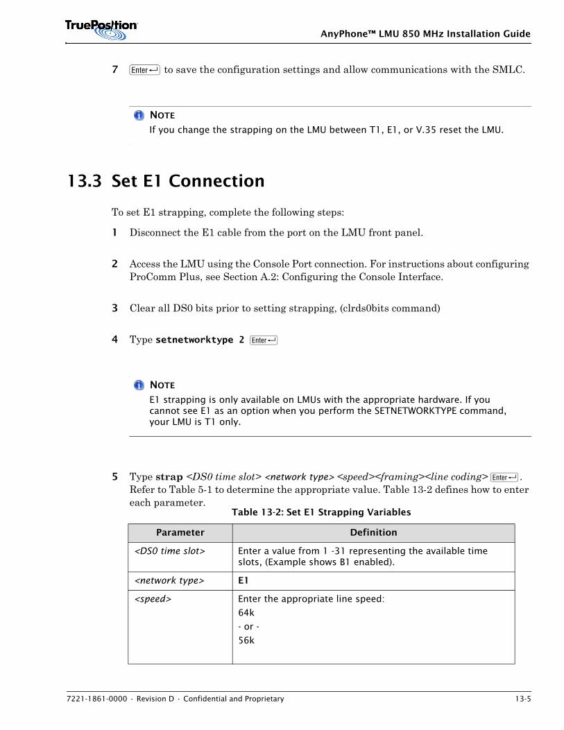
AnyPhone™ LMU 850 MHz Installation Guide
7221-1861-0000 • Revision D • Confidential and Proprietary 13-5
7 R to save the configuration settings and allow communications with the SMLC.
NOTE
If you change the strapping on the LMU between T1, E1, or V.35 reset the LMU.
13.3 Set E1 Connection
To set E1 strapping, complete the following steps:
1 Disconnect the E1 cable from the port on the LMU front panel.
2 Access the LMU using the Console Port connection. For instructions about configuring ProComm Plus, see Section A.2: Configuring the Console Interface.
3 Clear all DS0 bits prior to setting strapping, (clrds0bits command)
4 Type setnetworktype 2 R
NOTE
E1 strapping is only available on LMUs with the appropriate hardware. If you cannot see E1 as an option when you perform the SETNETWORKTYPE command, your LMU is T1 only.
5 Type strap <DS0 time slot> <network type> <speed><framing><line coding> R. Refer to Table 5-1 to determine the appropriate value. Table 13-2 defines how to enter each parameter.
Table 13-2: Set E1 Strapping Variables
Parameter Definition
<DS0 time slot> Enter a value from 1 -31 representing the available time slots, (Example shows B1 enabled).
<network type> E1
<speed> Enter the appropriate line speed:
64k
- or -
56k
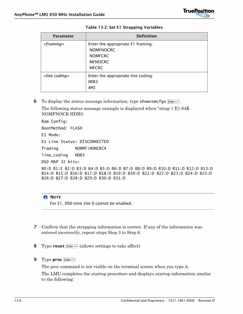
AnyPhone™ LMU 850 MHz Installation Guide
13-6 Confidential and Proprietary • 7221-1861-0000 • Revision D
6 To display the status message information, type showcomcfgs R.The following status message example is displayed when “strap 1 E1 64K NOMFNOCR HDB3:Ram Config:
BootMethod: FLASH
E1 Mode:
E1 Line Status: DISCONNECTED
framing NONMF|NONCRC4
line_coding HDB3
DS0 MAP 32 bits:
B0:D B1:E B2:D B3:D B4:D B5:D B6:D B7:D B8:D B9:D B10:D B11:D B12:D B13:D B14:D B15:D B16:D B17:D B18:D B19:D B20:D B21:D B22:D B23:D B24:D B25:D B26:D B27:D B28:D B29:D B30:D B31:D
NOTE
For E1, DS0 time slot 0 cannot be enabled.
7 Confirm that the strapping information is correct. If any of the information was entered incorrectly, repeat steps Step 3 to Step 6.
8 Type reset R (allows settings to take affect)
9 Type proc R The proc command is not visible on the terminal screen when you type it. The LMU completes the startup procedure and displays startup information similar to the following:
<framing> Enter the appropriate E1 framing:
NOMFNOCRC
NOMFCRC
MFNOCRC
MFCRC
<line coding> Enter the appropriate line coding:
HDB3
AMI
Table 13-2: Set E1 Strapping Variables
Parameter Definition
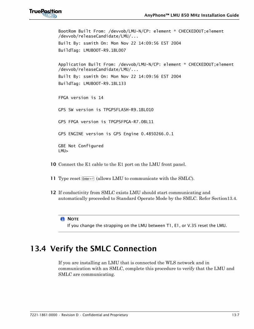
AnyPhone™ LMU 850 MHz Installation Guide
7221-1861-0000 • Revision D • Confidential and Proprietary 13-7
BootRom Built From: /devvob/LMU-N/CP: element * CHECKEDOUT;element /devvob/releaseCandidate/LMU/...
Built By: ssmith On: Mon Nov 22 14:09:56 EST 2004
BuildTag: LMUBOOT-R9.1BL007
Application Built From: /devvob/LMU-N/CP: element * CHECKEDOUT;element /devvob/releaseCandidate/LMU/...
Built By: ssmith On: Mon Nov 22 14:09:56 EST 2004
BuildTag: LMUBOOT-R9.1BL133
FPGA version is 14
GPS SW version is TPGPSFLASH-R9.1BL010
GPS FPGA version is TPGPSFPGA-R7.0BL11
GPS ENGINE version is GPS Engine 0.4850266.0.1
GBE Not ConfiguredLMU>
10 Connect the E1 cable to the E1 port on the LMU front panel.
11 Type reset R (allows LMU to communicate with the SMLC).
12 If conductivity from SMLC exists LMU should start communicating and automatically proceeded to Standard Operate Mode by the SMLC. Refer Section13.4.
NOTE
If you change the strapping on the LMU between T1, E1, or V.35 reset the LMU.
13.4 Verify the SMLC Connection
If you are installing an LMU that is connected the WLS network and in communication with an SMLC, complete this procedure to verify that the LMU and SMLC are communicating.
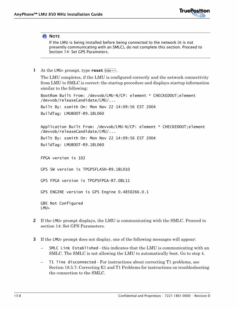
AnyPhone™ LMU 850 MHz Installation Guide
13-8 Confidential and Proprietary • 7221-1861-0000 • Revision D
NOTE
If the LMU is being installed before being connected to the network (it is not presently communicating with an SMLC), do not complete this section. Proceed to Section 14: Set GPS Parameters.
1 At the LMU> prompt, type reset R. The LMU completes, if the LMU is configured correctly and the network connectivity from LMU to SMLC is correct: the startup procedure and displays startup information similar to the following:BootRom Built From: /devvob/LMU-N/CP: element * CHECKEDOUT;element /devvob/releaseCandidate/LMU/...
Built By: ssmith On: Mon Nov 22 14:09:56 EST 2004
BuildTag: LMUBOOT-R9.1BL060
Application Built From: /devvob/LMU-N/CP: element * CHECKEDOUT;element /devvob/releaseCandidate/LMU/...
Built By: ssmith On: Mon Nov 22 14:09:56 EST 2004
BuildTag: LMUBOOT-R9.1BL060
FPGA version is 102
GPS SW version is TPGPSFLASH-R9.1BL010
GPS FPGA version is TPGPSFPGA-R7.0BL11
GPS ENGINE version is GPS Engine 0.4850266.0.1
GBE Not ConfiguredLMU>
2 If the LMU> prompt displays, the LMU is communicating with the SMLC. Proceed to section 14: Set GPS Parameters.
3 If the LMU> prompt does not display, one of the following messages will appear:
– SMLC Link Established - this indicates that the LMU is communicating with an SMLC. The SMLC is not allowing the LMU to automatically boot. Go to step 4.
– T1 line disconnected - For instructions about correcting T1 problems, see Section 18.5.7: Correcting E1 and T1 Problems for instructions on troubleshooting the connection to the SMLC.
AnyPhone™ LMU 850 MHz Installation Guide
7221-1861-0000 • Revision D • Confidential and Proprietary 13-9
NOTE
If no message displays, check your strapping and verify that you entered the correct values. Make necessary corrections. If the strapping values are entered correctly see Section 18.5.7: Correcting E1 and T1 Problems for instructions on troubleshooting the connection to the SMLC.
4 If the SMLC “Link Established” message is displayed, but the LMU does not display the messages and LMU> prompt as indicated in Step 1 in this list, then one of the following exists:
a) LMU proceeded to the target shell (Tshell) because of an abnormal condition (i.e.,No GPS Signal). this can be confirmed by R observing the --> prompt. The LMU can be manually placed in the Standard Operate mode via the Tshell R command.
b) LMU stayed in the BOOT state (LMU displayed BOOT> or LMUBOOT> prompt) for other reasons, such as, incorrect configuration and/or connectivity to SMLC. The LMU can be manually proceeded into the Standard Operate state via the proc R command.
5 The proc command is not visible on the terminal screen when you type it. When the LMU completes booting, the LMU> displays.

AnyPhone™ LMU 850 MHz Installation Guide
13-10 Confidential and Proprietary • 7221-1861-0000 • Revision D
AnyPhone™ LMU 850 MHz Installation Guide
7221-1861-0000 • Revision D • Confidential and Proprietary 14-1
14. SET GPS PARAMETERS
Contents14.1 Preparation . . . . . . . . . . . . . . . . . . . . . . . . . . . . . . . . . . . . . . . . . . . . . . . . . . . . . . . . . . 14-114.2 GPS Antenna Position . . . . . . . . . . . . . . . . . . . . . . . . . . . . . . . . . . . . . . . . . . . . . . . . . . 14-114.3 Setting the GPS Parameters . . . . . . . . . . . . . . . . . . . . . . . . . . . . . . . . . . . . . . . . . . . . . . 14-3
To set GPS parameters, determine the GPS location, then configure the LMU.
14.1 Preparation
Obtain the GPS latitude and longitude information from Table 5-1, Vital Information before performing the checkout procedure.
If you are installing an LMU for BTS Synchronization, you must obtain the altitude measured in meters in ellipsod.
GPS latitude and longitude values are required for configuring the LMU for the GPS antenna position. If you have not already done so, record these eight or nine digit values in the appropriate spaces provided in the Vital Information Table.
14.2 GPS Antenna Position
This section defines the requirements for formatting longitude, latitude and altitude values you enter in the LMU Console Port. Configure the GPS antenna position prior to operation. The configuration data you enter is used until a configuration is downloaded from the WLS. If not entered, default data is used.
!CAUTION
If you do not format the Latitude and Longitude values for the GPS antenna position correctly, the LMU will not function properly.
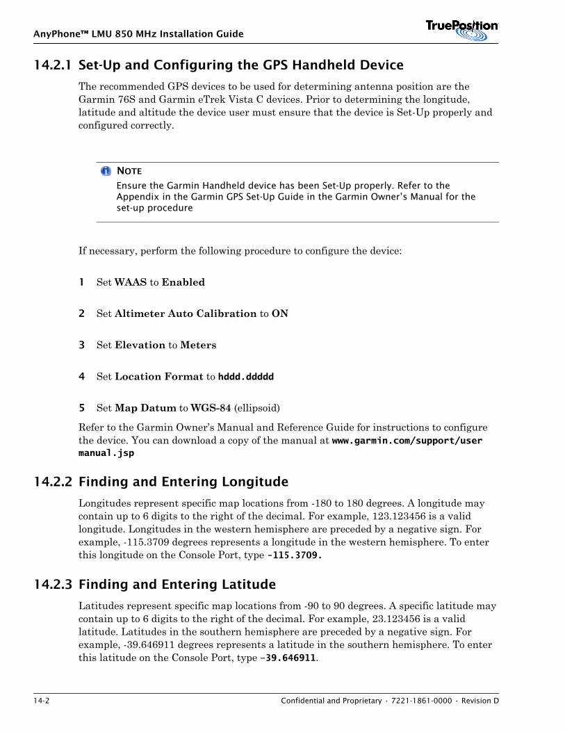
AnyPhone™ LMU 850 MHz Installation Guide
14-2 Confidential and Proprietary • 7221-1861-0000 • Revision D
14.2.1 Set-Up and Configuring the GPS Handheld Device
The recommended GPS devices to be used for determining antenna position are the Garmin 76S and Garmin eTrek Vista C devices. Prior to determining the longitude, latitude and altitude the device user must ensure that the device is Set-Up properly and configured correctly.
NOTE
Ensure the Garmin Handheld device has been Set-Up properly. Refer to the Appendix in the Garmin GPS Set-Up Guide in the Garmin Owner’s Manual for the set-up procedure
If necessary, perform the following procedure to configure the device:
1 Set WAAS to Enabled
2 Set Altimeter Auto Calibration to ON
3 Set Elevation to Meters
4 Set Location Format to hddd.ddddd
5 Set Map Datum to WGS-84 (ellipsoid)
Refer to the Garmin Owner’s Manual and Reference Guide for instructions to configure the device. You can download a copy of the manual at www.garmin.com/support/user manual.jsp
14.2.2 Finding and Entering Longitude
Longitudes represent specific map locations from -180 to 180 degrees. A longitude may contain up to 6 digits to the right of the decimal. For example, 123.123456 is a valid longitude. Longitudes in the western hemisphere are preceded by a negative sign. For example, -115.3709 degrees represents a longitude in the western hemisphere. To enter this longitude on the Console Port, type -115.3709.
14.2.3 Finding and Entering Latitude
Latitudes represent specific map locations from -90 to 90 degrees. A specific latitude may contain up to 6 digits to the right of the decimal. For example, 23.123456 is a valid latitude. Latitudes in the southern hemisphere are preceded by a negative sign. For example, -39.646911 degrees represents a latitude in the southern hemisphere. To enter this latitude on the Console Port, type –39.646911.
AnyPhone™ LMU 850 MHz Installation Guide
7221-1861-0000 • Revision D • Confidential and Proprietary 14-3
14.2.4 Finding and Entering Altitude
Perform the following procedure to obtain the altitude parameter:
1 With the GPS receiver powered ON, position it vertically at the base of the antenna.
NOTE
Wait five minutes before recording the Elevation parameter.
2 Record the Elevation displayed.
3 Add the height of the antenna to the Elevation reading.
4 The combination is the altitude of the site antenna.
5 Enter the altitude parameter on the Console Port and Site Survey form.
NOTE
GPS parameters in the SCOUT configuration files overwrite the value if a Site Survey is not submitted for configuration file update.
14.3 Setting the GPS Parameters
This section defines how to configure the GPS antenna latitude, longitude, antenna delay, and antenna altitude. Refer to Section 14.2: GPS Antenna Position for constraints on these values.
NOTE
Commands entered on the ProComm window do not display.
To set GPS parameters and check status of the GPS:
1 Disconnect the LMU T1/E1 connection.
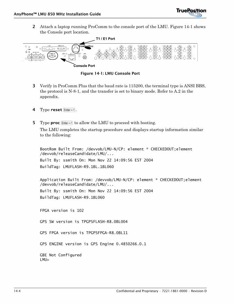
AnyPhone™ LMU 850 MHz Installation Guide
14-4 Confidential and Proprietary • 7221-1861-0000 • Revision D
2 Attach a laptop running ProComm to the console port of the LMU. Figure 14-1 shows the Console port location.
Figure 14-1: LMU Console Port
3 Verify in ProComm Plus that the baud rate is 115200, the terminal type is ANSI BBS, the protocol is N-8-1, and the transfer is set to binary mode. Refer to A.2 in the appendix.
4 Type reset R.
5 Type proc R to allow the LMU to proceed with booting. The LMU completes the startup procedure and displays startup information similar to the following:
BootRom Built From: /devvob/LMU-N/CP: element * CHECKEDOUT;element /devvob/releaseCandidate/LMU/...
Built By: ssmith On: Mon Nov 22 14:09:56 EST 2004
BuildTag: LMUFLASH-R9.1BL.1BL060
Application Built From: /devvob/LMU-N/CP: element * CHECKEDOUT;element /devvob/releaseCandidate/LMU/...
Built By: ssmith On: Mon Nov 22 14:09:56 EST 2004
BuildTag: LMUFLASH-R9.1BL060
FPGA version is 102
GPS SW version is TPGPSFLASH-R8.0BL004
GPS FPGA version is TPGPSFPGA-R8.0BL11
GPS ENGINE version is GPS Engine 0.4850266.0.1
GBE Not ConfiguredLMU>
Console Port
T1 / E1 Port
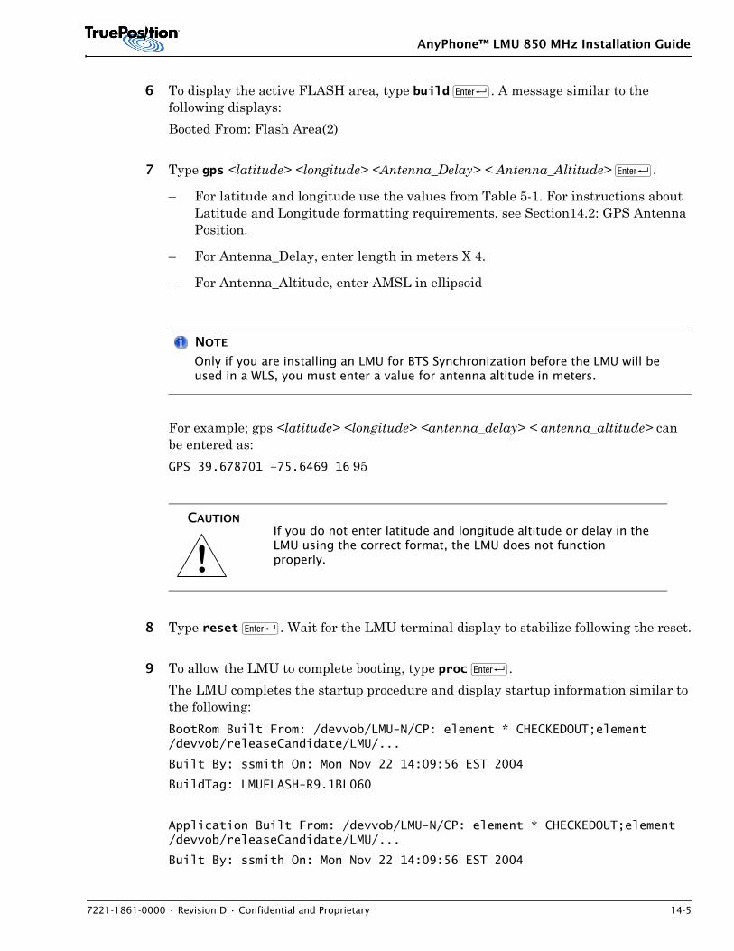
AnyPhone™ LMU 850 MHz Installation Guide
7221-1861-0000 • Revision D • Confidential and Proprietary 14-5
6 To display the active FLASH area, type build R. A message similar to the following displays:Booted From: Flash Area(2)
7 Type gps <latitude> <longitude> <Antenna_Delay> < Antenna_Altitude> R.
– For latitude and longitude use the values from Table 5-1. For instructions about Latitude and Longitude formatting requirements, see Section14.2: GPS Antenna Position.
– For Antenna_Delay, enter length in meters X 4.
– For Antenna_Altitude, enter AMSL in ellipsoid
NOTE
Only if you are installing an LMU for BTS Synchronization before the LMU will be used in a WLS, you must enter a value for antenna altitude in meters.
For example; gps <latitude> <longitude> <antenna_delay> < antenna_altitude> can be entered as:GPS 39.678701 –75.6469 16 95
8 Type reset R. Wait for the LMU terminal display to stabilize following the reset.
9 To allow the LMU to complete booting, type proc R. The LMU completes the startup procedure and display startup information similar to the following:BootRom Built From: /devvob/LMU-N/CP: element * CHECKEDOUT;element /devvob/releaseCandidate/LMU/...
Built By: ssmith On: Mon Nov 22 14:09:56 EST 2004
BuildTag: LMUFLASH-R9.1BL060
Application Built From: /devvob/LMU-N/CP: element * CHECKEDOUT;element /devvob/releaseCandidate/LMU/...
Built By: ssmith On: Mon Nov 22 14:09:56 EST 2004
!CAUTION
If you do not enter latitude and longitude altitude or delay in the LMU using the correct format, the LMU does not function properly.
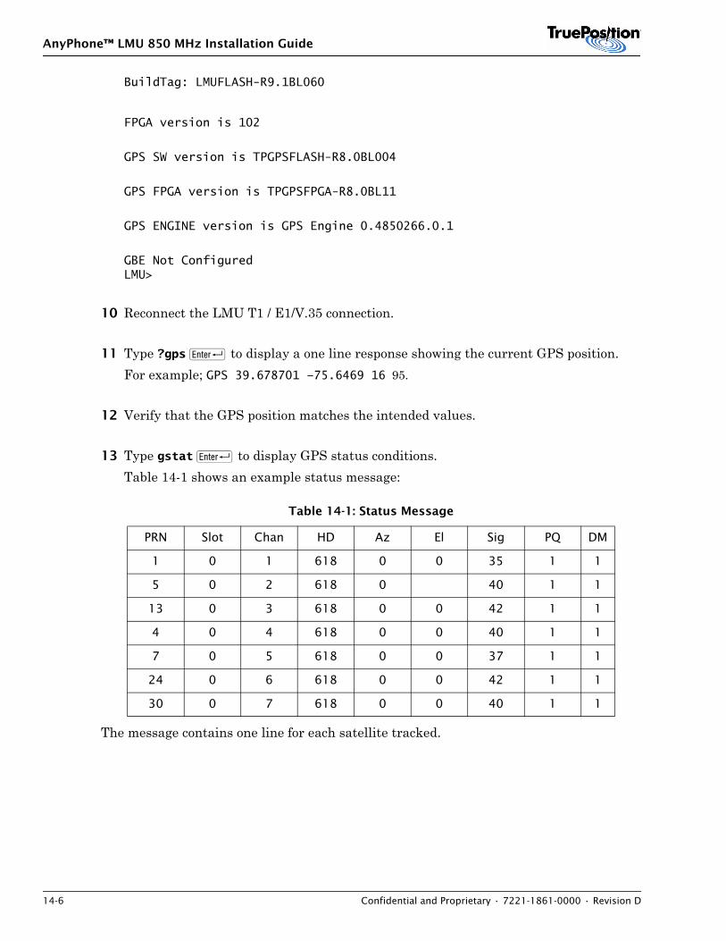
AnyPhone™ LMU 850 MHz Installation Guide
14-6 Confidential and Proprietary • 7221-1861-0000 • Revision D
BuildTag: LMUFLASH-R9.1BL060
FPGA version is 102
GPS SW version is TPGPSFLASH-R8.0BL004
GPS FPGA version is TPGPSFPGA-R8.0BL11
GPS ENGINE version is GPS Engine 0.4850266.0.1
GBE Not ConfiguredLMU>
10 Reconnect the LMU T1 / E1/V.35 connection.
11 Type ?gps R to display a one line response showing the current GPS position. For example; GPS 39.678701 –75.6469 16 95.
12 Verify that the GPS position matches the intended values.
13 Type gstat R to display GPS status conditions. Table 14-1 shows an example status message:
The message contains one line for each satellite tracked.
Table 14-1: Status Message
PRN Slot Chan HD Az El Sig PQ DM
1 0 1 618 0 0 35 1 1
5 0 2 618 0 40 1 1
13 0 3 618 0 0 42 1 1
4 0 4 618 0 0 40 1 1
7 0 5 618 0 0 37 1 1
24 0 6 618 0 0 42 1 1
30 0 7 618 0 0 40 1 1
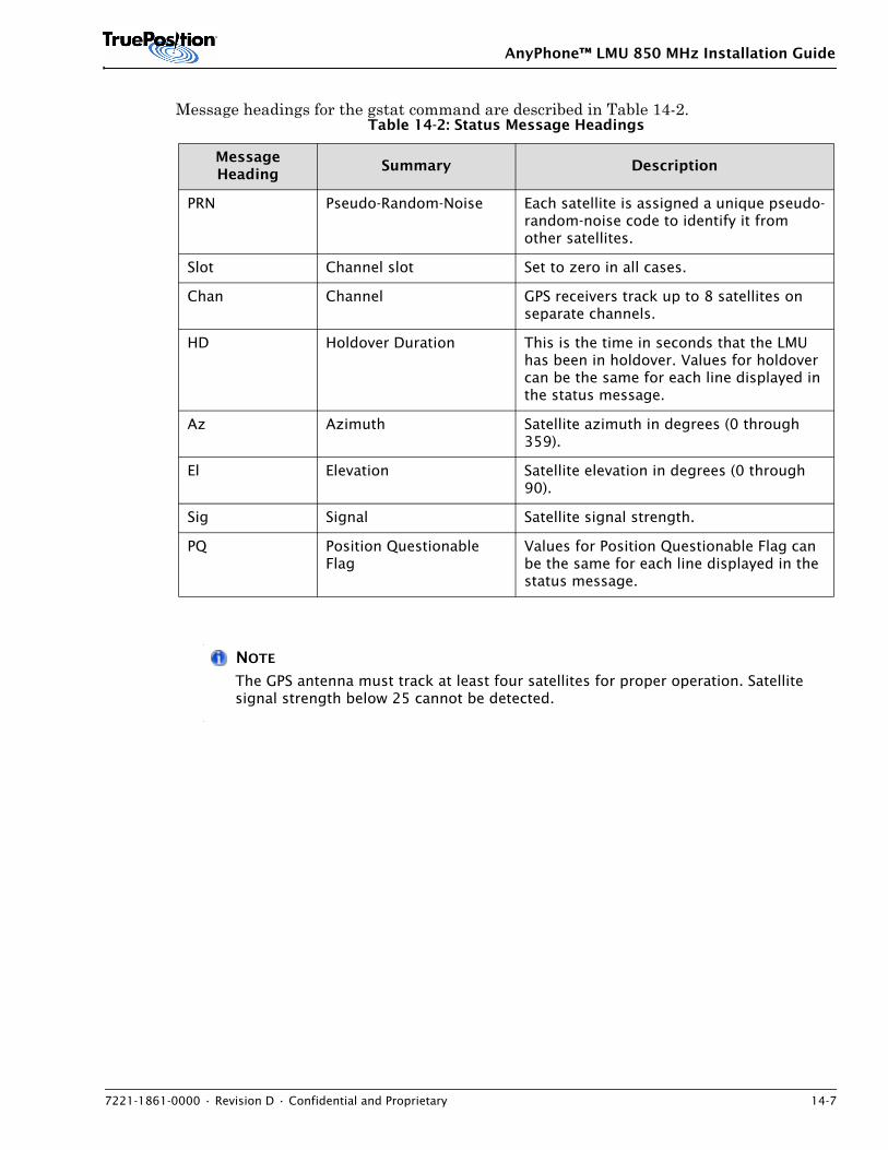
AnyPhone™ LMU 850 MHz Installation Guide
7221-1861-0000 • Revision D • Confidential and Proprietary 14-7
Message headings for the gstat command are described in Table 14-2.
NOTE
The GPS antenna must track at least four satellites for proper operation. Satellite signal strength below 25 cannot be detected.
Table 14-2: Status Message Headings
Message Heading
Summary Description
PRN Pseudo-Random-Noise Each satellite is assigned a unique pseudo-random-noise code to identify it from other satellites.
Slot Channel slot Set to zero in all cases.
Chan Channel GPS receivers track up to 8 satellites on separate channels.
HD Holdover Duration This is the time in seconds that the LMU has been in holdover. Values for holdover can be the same for each line displayed in the status message.
Az Azimuth Satellite azimuth in degrees (0 through 359).
El Elevation Satellite elevation in degrees (0 through 90).
Sig Signal Satellite signal strength.
PQ Position Questionable Flag
Values for Position Questionable Flag can be the same for each line displayed in the status message.

AnyPhone™ LMU 850 MHz Installation Guide
14-8 Confidential and Proprietary • 7221-1861-0000 • Revision D
AnyPhone ™ LMU 850 / 1900 MHz Dual Band Installation Guide
7221-1862-0000 • Revision D • Confidential and Proprietary 15-1
15. DUAL BAND RF SIGNAL TEST
Contents15.1 Introduction . . . . . . . . . . . . . . . . . . . . . . . . . . . . . . . . . . . . . . . . . . . . . . . . . . . . . . . . . 15-115.2 Bit 6 Command Parameters . . . . . . . . . . . . . . . . . . . . . . . . . . . . . . . . . . . . . . . . . . . . . . 15-315.3 Bit 6 Test Sequence . . . . . . . . . . . . . . . . . . . . . . . . . . . . . . . . . . . . . . . . . . . . . . . . . . . . 15-515.4 Channel Boundaries . . . . . . . . . . . . . . . . . . . . . . . . . . . . . . . . . . . . . . . . . . . . . . . . . . . . 15-615.5 Bit 6 Evaluation . . . . . . . . . . . . . . . . . . . . . . . . . . . . . . . . . . . . . . . . . . . . . . . . . . . . . . . 15-8
15.1 Introduction
This section defines the test procedure for evaluating LMU RF ports using the BIT 6 test.
The RF path test evaluates the LMU port connection. The test determines if the LMU RF path is adequate for receiving transmissions and sensing mobile subscriber transmissions. The procedure provides pass or fail results.
RF path and mobile transmissions are evaluated by comparing the noise floor against the
connected cable.
• For an LMU with a normal gain or no block down converter, optimal results require the multi coupler gain to be at least 10 dB. If the signal is between 6 and 9 dB, the results may not be accurate. If the signal is less than 6dB, results are invalid.
• For an LMU configured with a high gain block down converter or a high gain receiver, optimal results require the multi coupler gain to be at least 20 dB. If the signal is between 16 and 19 dB, the results may not be accurate. If the signal is less than 16dB, results are invalid.
• For an LMU with a high gain block down converter and a high gain receiver, optimal results require the multi coupler gain to be at least 30 dB. If the signal is between 26 and 29 dB, the results may not be accurate. If the signal is less than 26dB, results are invalid.
To perform the RF signal test, complete the following steps:
1 Obtain the appropriate channels that are available for testing from the local market.If you perform the testing using a channel that is not available, the message BIT 6 Bad Parameter Value(s) displays.
AnyPhone ™ LMU 850 / 1900 MHz Dual Band Installation Guide
15-2 Confidential and Proprietary • 7221-1862-0000 • Revision D
NOTE
The appropriate channels to test may be ascertained by reviewing the results of the Searchbcn test in absence of the appropriate channels from the local market.
2 For GSM installations only, you must disable the Beacon Search before performing this test or the results will not be reliable. To stop the Beacon Search, type Searchbcn none
3 Prior to testing each port you must use the gains command to maximize gains on the port.
4 Test the RF signal with the cables connected to the LMU following the instructions in sections 15.2 through 15.5. For a dual-band LMU you must perform this test on the 850 MHz and 1900 MHz bands.
5 Remove the cables from the LMU ports and test the RF noise floor following the instructions in sections 15.2 through 15.5. For a dual-band LMU you must perform this test on the 850 MHz and 1900 MHz bands.
6 Make a copy of Table 15-6 and record your results there. For dual band you need two copies of Table 15-7.
7 Record your results on your copy(s) of Table 15-7.
8 For instructions about how to evaluate the data entered in Table 15-7, refer to Section 15.5
9 When the test is complete, reset the LMU.
The following subsections define performing the test on each frequency band and describe how to record and evaluate the results. Figure 15-1 illustrates the function of the RF path test
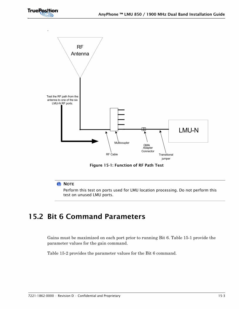
AnyPhone ™ LMU 850 / 1900 MHz Dual Band Installation Guide
7221-1862-0000 • Revision D • Confidential and Proprietary 15-3
.
Figure 15-1: Function of RF Path Test
NOTE
Perform this test on ports used for LMU location processing. Do not perform this test on unused LMU ports.
15.2 Bit 6 Command Parameters
Gains must be maximized on each port prior to running Bit 6. Table 15-1 provide the parameter values for the gain command.
Table 15-2 provides the parameter values for the Bit 6 command.
LMU-N
Multicoupler
RFAntenna
RF Cable
QMAAdapter
ConnectorTransitional
jumper
Test the RF path from theantenna to one of the six
LMU-N RF ports.
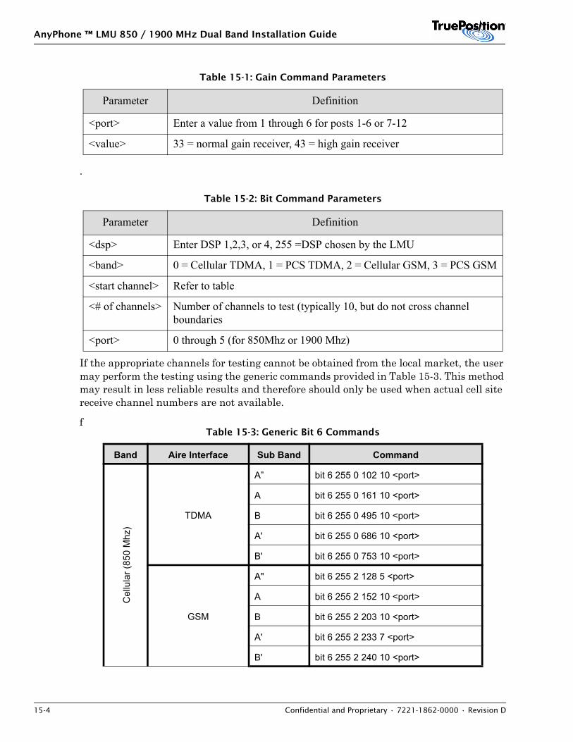
AnyPhone ™ LMU 850 / 1900 MHz Dual Band Installation Guide
15-4 Confidential and Proprietary • 7221-1862-0000 • Revision D
.
If the appropriate channels for testing cannot be obtained from the local market, the user may perform the testing using the generic commands provided in Table 15-3. This method may result in less reliable results and therefore should only be used when actual cell site receive channel numbers are not available.
f
Table 15-1: Gain Command Parameters
Parameter Definition
<port> Enter a value from 1 through 6 for posts 1-6 or 7-12
<value> 33 = normal gain receiver, 43 = high gain receiver
Table 15-2: Bit Command Parameters
Parameter Definition
<dsp> Enter DSP 1,2,3, or 4, 255 =DSP chosen by the LMU
<band> 0 = Cellular TDMA, 1 = PCS TDMA, 2 = Cellular GSM, 3 = PCS GSM
<start channel> Refer to table
<# of channels> Number of channels to test (typically 10, but do not cross channel boundaries
<port> 0 through 5 (for 850Mhz or 1900 Mhz)
Table 15-3: Generic Bit 6 Commands
Band Aire Interface Sub Band Command
Cel
lula
r (85
0 M
hz)
TDMA
A” bit 6 255 0 102 10 <port>
A bit 6 255 0 161 10 <port>
B bit 6 255 0 495 10 <port>
A' bit 6 255 0 686 10 <port>
B' bit 6 255 0 753 10 <port>
GSM
A" bit 6 255 2 128 5 <port>
A bit 6 255 2 152 10 <port>
B bit 6 255 2 203 10 <port>
A' bit 6 255 2 233 7 <port>
B' bit 6 255 2 240 10 <port>
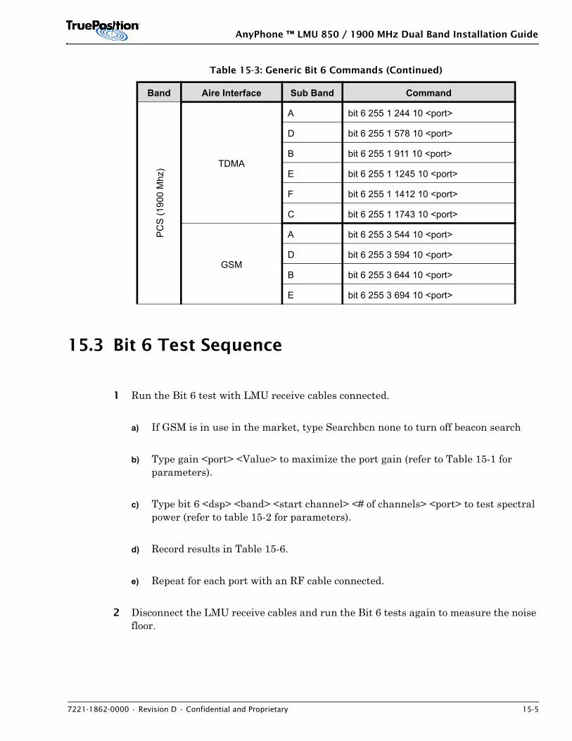
AnyPhone ™ LMU 850 / 1900 MHz Dual Band Installation Guide
7221-1862-0000 • Revision D • Confidential and Proprietary 15-5
15.3 Bit 6 Test Sequence
1 Run the Bit 6 test with LMU receive cables connected.
a) If GSM is in use in the market, type Searchbcn none to turn off beacon search
b) Type gain <port> <Value> to maximize the port gain (refer to Table 15-1 for parameters).
c) Type bit 6 <dsp> <band> <start channel> <# of channels> <port> to test spectral power (refer to table 15-2 for parameters).
d) Record results in Table 15-6.
e) Repeat for each port with an RF cable connected.
2 Disconnect the LMU receive cables and run the Bit 6 tests again to measure the noise floor.
PC
S (1
900
Mhz
) TDMA
A bit 6 255 1 244 10 <port>
D bit 6 255 1 578 10 <port>
B bit 6 255 1 911 10 <port>
E bit 6 255 1 1245 10 <port>
F bit 6 255 1 1412 10 <port>
C bit 6 255 1 1743 10 <port>
GSM
A bit 6 255 3 544 10 <port>
D bit 6 255 3 594 10 <port>
B bit 6 255 3 644 10 <port>
E bit 6 255 3 694 10 <port>
Table 15-3: Generic Bit 6 Commands (Continued)
Band Aire Interface Sub Band Command
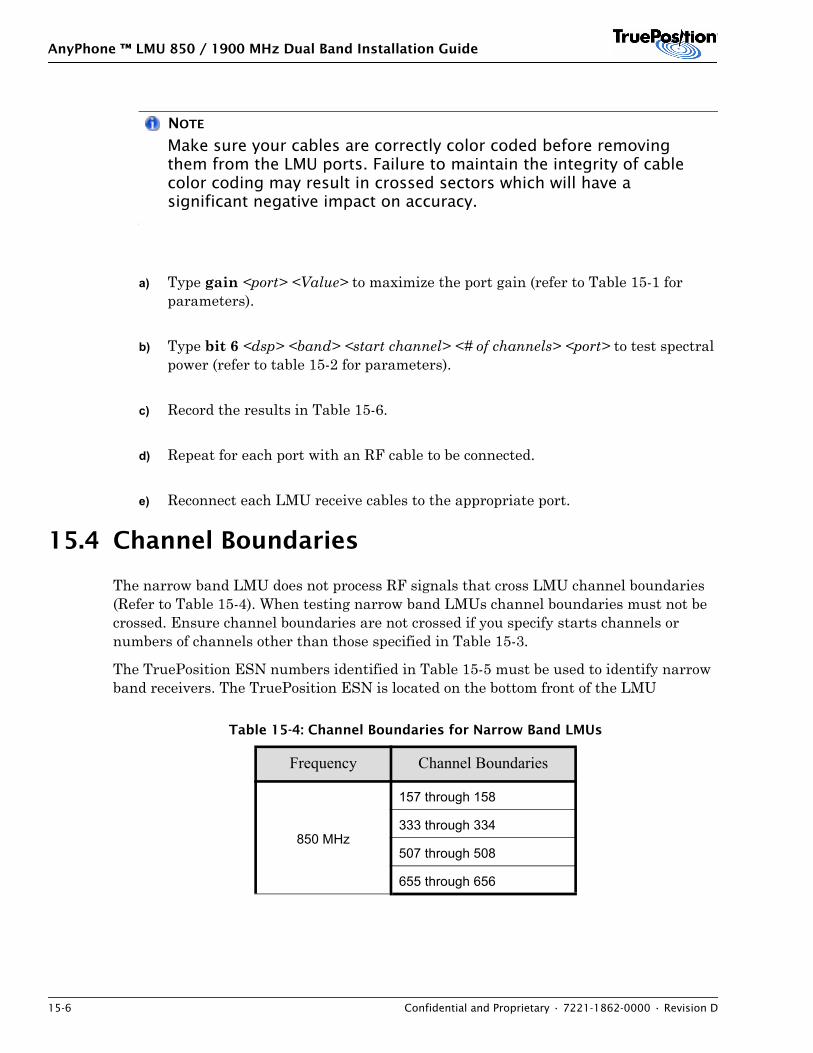
AnyPhone ™ LMU 850 / 1900 MHz Dual Band Installation Guide
15-6 Confidential and Proprietary • 7221-1862-0000 • Revision D
NOTE
Make sure your cables are correctly color coded before removing them from the LMU ports. Failure to maintain the integrity of cable color coding may result in crossed sectors which will have a significant negative impact on accuracy.
a) Type gain <port> <Value> to maximize the port gain (refer to Table 15-1 for parameters).
b) Type bit 6 <dsp> <band> <start channel> <# of channels> <port> to test spectral power (refer to table 15-2 for parameters).
c) Record the results in Table 15-6.
d) Repeat for each port with an RF cable to be connected.
e) Reconnect each LMU receive cables to the appropriate port.
15.4 Channel Boundaries
The narrow band LMU does not process RF signals that cross LMU channel boundaries (Refer to Table 15-4). When testing narrow band LMUs channel boundaries must not be crossed. Ensure channel boundaries are not crossed if you specify starts channels or numbers of channels other than those specified in Table 15-3.
The TruePosition ESN numbers identified in Table 15-5 must be used to identify narrow band receivers. The TruePosition ESN is located on the bottom front of the LMU
Table 15-4: Channel Boundaries for Narrow Band LMUs
Frequency Channel Boundaries
850 MHz
157 through 158
333 through 334
507 through 508
655 through 656
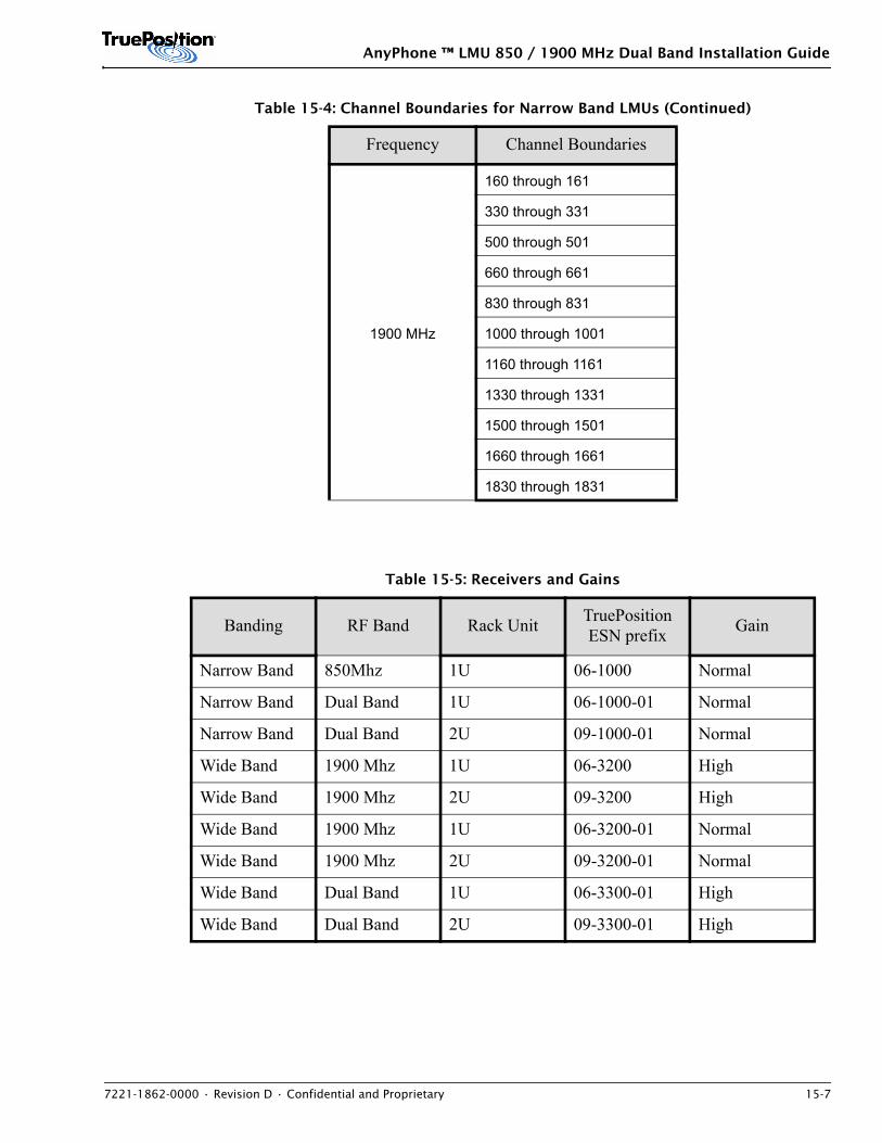
AnyPhone ™ LMU 850 / 1900 MHz Dual Band Installation Guide
7221-1862-0000 • Revision D • Confidential and Proprietary 15-7
1900 MHz
160 through 161
330 through 331
500 through 501
660 through 661
830 through 831
1000 through 1001
1160 through 1161
1330 through 1331
1500 through 1501
1660 through 1661
1830 through 1831
Table 15-5: Receivers and Gains
Banding RF Band Rack Unit TruePosition ESN prefix Gain
Narrow Band 850Mhz 1U 06-1000 Normal
Narrow Band Dual Band 1U 06-1000-01 Normal
Narrow Band Dual Band 2U 09-1000-01 Normal
Wide Band 1900 Mhz 1U 06-3200 High
Wide Band 1900 Mhz 2U 09-3200 High
Wide Band 1900 Mhz 1U 06-3200-01 Normal
Wide Band 1900 Mhz 2U 09-3200-01 Normal
Wide Band Dual Band 1U 06-3300-01 High
Wide Band Dual Band 2U 09-3300-01 High
Table 15-4: Channel Boundaries for Narrow Band LMUs (Continued)
Frequency Channel Boundaries
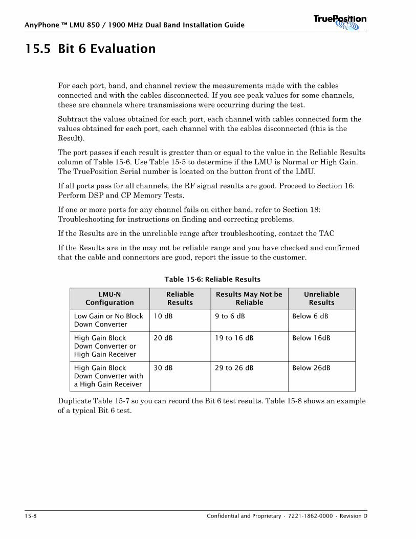
AnyPhone ™ LMU 850 / 1900 MHz Dual Band Installation Guide
15-8 Confidential and Proprietary • 7221-1862-0000 • Revision D
15.5 Bit 6 Evaluation
For each port, band, and channel review the measurements made with the cables connected and with the cables disconnected. If you see peak values for some channels, these are channels where transmissions were occurring during the test.
Subtract the values obtained for each port, each channel with cables connected form the values obtained for each port, each channel with the cables disconnected (this is the Result).
The port passes if each result is greater than or equal to the value in the Reliable Results column of Table 15-6. Use Table 15-5 to determine if the LMU is Normal or High Gain. The TruePosition Serial number is located on the button front of the LMU.
If all ports pass for all channels, the RF signal results are good. Proceed to Section 16: Perform DSP and CP Memory Tests.
If one or more ports for any channel fails on either band, refer to Section 18: Troubleshooting for instructions on finding and correcting problems.
If the Results are in the unreliable range after troubleshooting, contact the TAC
If the Results are in the may not be reliable range and you have checked and confirmed that the cable and connectors are good, report the issue to the customer.
Duplicate Table 15-7 so you can record the Bit 6 test results. Table 15-8 shows an example of a typical Bit 6 test.
Table 15-6: Reliable Results
LMU-N Configuration
Reliable Results
Results May Not be Reliable
Unreliable Results
Low Gain or No Block Down Converter
10 dB 9 to 6 dB Below 6 dB
High Gain Block Down Converter or High Gain Receiver
20 dB 19 to 16 dB Below 16dB
High Gain Block Down Converter with a High Gain Receiver
30 dB 29 to 26 dB Below 26dB
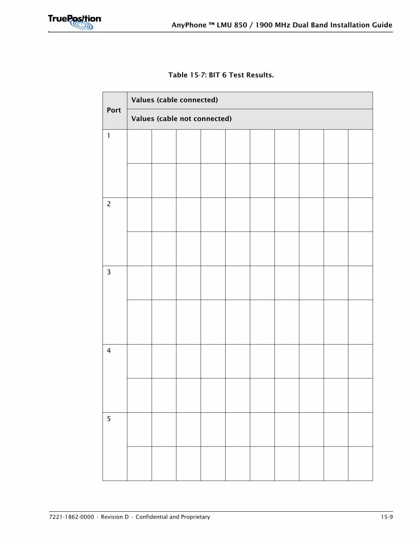
AnyPhone ™ LMU 850 / 1900 MHz Dual Band Installation Guide
7221-1862-0000 • Revision D • Confidential and Proprietary 15-9
Table 15-7: BIT 6 Test Results.
Port
Values (cable connected)
Values (cable not connected)
1
2
3
4
5
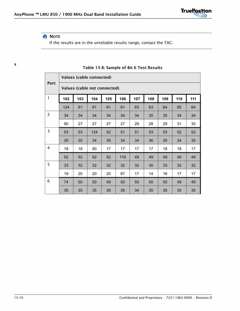
AnyPhone ™ LMU 850 / 1900 MHz Dual Band Installation Guide
15-10 Confidential and Proprietary • 7221-1862-0000 • Revision D
NOTE
If the results are in the unreliable results range, contact the TAC.
sTable 15-8: Sample of Bit 6 Test Results
Port
Values (cable connected)
Values (cable not connected)
1 102 103 104 105 106 107 108 109 110 111
124 61 61 61 61 63 63 64 65 64
2 34 34 34 34 34 34 35 35 34 34
90 27 27 27 27 29 28 29 31 30
3 53 53 124 52 51 51 53 53 52 52
35 35 34 35 34 34 36 35 34 35
4 18 18 90 17 17 17 17 18 18 17
52 52 52 52 119 49 49 49 49 49
5 33 32 32 32 32 32 35 33 32 32
19 20 20 20 87 17 14 16 17 17
6 74 50 50 49 50 50 50 50 49 49
35 35 35 35 35 34 35 35 35 35
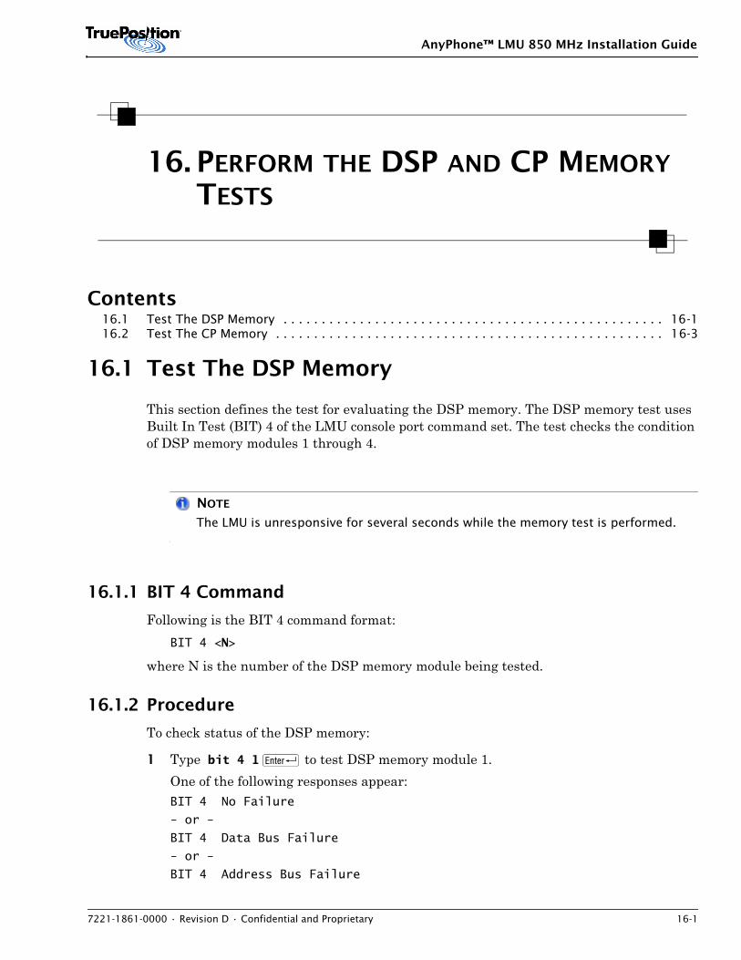
AnyPhone™ LMU 850 MHz Installation Guide
7221-1861-0000 • Revision D • Confidential and Proprietary 16-1
16. PERFORM THE DSP AND CP MEMORY TESTS
Contents16.1 Test The DSP Memory . . . . . . . . . . . . . . . . . . . . . . . . . . . . . . . . . . . . . . . . . . . . . . . . . . 16-116.2 Test The CP Memory . . . . . . . . . . . . . . . . . . . . . . . . . . . . . . . . . . . . . . . . . . . . . . . . . . . 16-3
16.1 Test The DSP Memory
This section defines the test for evaluating the DSP memory. The DSP memory test uses Built In Test (BIT) 4 of the LMU console port command set. The test checks the condition of DSP memory modules 1 through 4.
NOTE
The LMU is unresponsive for several seconds while the memory test is performed.
16.1.1 BIT 4 Command
Following is the BIT 4 command format:BIT 4 <N>
where N is the number of the DSP memory module being tested.
16.1.2 Procedure
To check status of the DSP memory:
1 Type bit 4 1 R to test DSP memory module 1. One of the following responses appear: BIT 4 No Failure
- or -
BIT 4 Data Bus Failure
- or -
BIT 4 Address Bus Failure
AnyPhone™ LMU 850 MHz Installation Guide
16-2 Confidential and Proprietary • 7221-1861-0000 • Revision D
- or -
BIT 4 Device Failure
2 Type bit 4 2 R to test DSP memory module 2. One of the following responses appear: BIT 4 No Failure
- or -
BIT 4 Data Bus Failure
- or -
BIT 4 Address Bus Failure
- or -
BIT 4 Device Failure
3 Type bit 4 3 R to test DSP memory module 3. One of the following responses appear: BIT 4 No Failure
- or -
BIT 4 Data Bus Failure
- or -
BIT 4 Address Bus Failure
- or -
BIT 4 Device Failure
4 Type bit 4 4 R to test DSP memory module 4. One of the following responses appear: BIT 4 No Failure
- or -
BIT 4 Data Bus Failure
- or -
BIT 4 Address Bus Failure
- or -
BIT 4 Device Failure
16.1.3 Evaluation
• If all of the DSP memory tests produce the message No Failure, proceed to Section 16.2: Test The CP Memory.
• If the result displays any message indicating failure for any test (for example Data Bus Failure), the LMU must be replaced.
AnyPhone™ LMU 850 MHz Installation Guide
7221-1861-0000 • Revision D • Confidential and Proprietary 16-3
16.2 Test The CP Memory
This section defines the procedure for evaluating the CP (central processor) memory. The CP memory test uses Built-in Test (BIT) 5 of the LMU console port command set. The test checks the condition of the central processor.
NOTE
The LMU is unresponsive for several seconds while the test is performed.
16.2.1 BIT 5 Command
Following is the BIT 5 command:BIT 5
16.2.2 Procedure
To check status of the CP memory:
Type bit 5 R.
Confirm that the status response is: CP RAM Memory Test Passed
orCP RAM Memory Test Failed at 0x...
where 0x is some memory address.
NOTE
The LMU reboots before the test results display.
16.2.3 Evaluation
• If the status response is CP RAM Memory Test Passed, the test passed.
• If the status response is CP RAM Memory Test Failed, the LMU must be replaced.

AnyPhone™ LMU 850 MHz Installation Guide
16-4 Confidential and Proprietary • 7221-1861-0000 • Revision D
AnyPhone ™ LMU 850 / 1900 MHz Dual Band Installation Guide
7221-1862-0000 • Revision D • Confidential and Proprietary 17-1
17. DUAL BAND GSM DOWNLINK ANTENNA TESTS
Contents17.1 Introduction . . . . . . . . . . . . . . . . . . . . . . . . . . . . . . . . . . . . . . . . . . . . . . . . . . . . . . . . . 17-117.2 GSM Downlink Antenna Power Test . . . . . . . . . . . . . . . . . . . . . . . . . . . . . . . . . . . . . . . . 17-117.3 GSM Beacon Search . . . . . . . . . . . . . . . . . . . . . . . . . . . . . . . . . . . . . . . . . . . . . . . . . . . . 17-217.4 System Level Testing . . . . . . . . . . . . . . . . . . . . . . . . . . . . . . . . . . . . . . . . . . . . . . . . . . . 17-3
17.1 Introduction
After installing the GSM downlink antenna at the cell site, perform the tests in this section using the Pro Comm window on the LMU to verify that the GSM system is functioning correctly.
NOTE
The LMU cannot perform location processing while performing the tests in this section.
17.2 GSM Downlink Antenna Power Test
This test measures the power level in dB across all channels received through the GSM downlink antenna and indicates whether the GSM downlink antenna is connected to the LMU and is functioning properly.
To perform the GSM downlink antenna test, enter the following command at the LMU> prompt:
1 Type bit 8 <parameter > R, where <parameter> is one of the following values:
– For 850 MHz, enter 4.
– FOR 1900 MHz, enter 5.
The GSM downlink antenna test takes up to three minutes to complete. When it is finished, the results display. Run the test for each band used by the LMU.
AnyPhone ™ LMU 850 / 1900 MHz Dual Band Installation Guide
17-2 Confidential and Proprietary • 7221-1862-0000 • Revision D
2 If BIT 8 PASSED displays, the installation is complete.
3 If BIT 8 FAILED displays, see 18.5.4: Troubleshoot GSM Downlink Antenna Power Test Failures.
NOTE
To complete the test for 850 MHz and 1900 MHz, you must perform the test once for each band.
17.3 GSM Beacon Search
Perform a GSM Beacon Search test to determine whether the LMU is receiving the proper channel information from the GSM downlink antenna. For a dual-band installation, perform the test twice (once for 850 MHz and once for 1900 MHz).
To perform the GSM Beacon Search test, complete the following steps:
1 To test channels in the 850 MHz band, type searchbcn cell R. The test takes three minutes to return a result. If the test passes, a message stating one or more beacons are found displays. Following is an example: LMU>search of Beacon Ranges has completed
In selftest, found 1 beacons
If the test fails, a message stating no beacons were found displays. The following is an example message: LMU>search of Beacon Ranges has completed
In selftest, found 0 beacons
2 To test channels in the 1900 MHz band, type searchbcn PCS R. The test takes three minutes to return a result. If the test passes, a message stating one or more beacons are found displays. Following is an example:
LMU>search of Beacon Ranges has completed
In selftest, found 1 beacons
AnyPhone ™ LMU 850 / 1900 MHz Dual Band Installation Guide
7221-1862-0000 • Revision D • Confidential and Proprietary 17-3
If the test fails, a message stating 0 beacons were found displays. The following is an example message: LMU>search of Beacon Ranges has completed
In selftest, found 0 beacons
NOTE
Searchbcn both runs both of the above tests.
3 If the 850 MHz and 1900 MHz tests pass, the GSM downlink antenna installation is complete.
4 If the test for either band fails, see 18.5.5: Troubleshooting the GSM Downlink Antenna Beacon Search Test Failure.
17.4 System Level Testing
Completing the above procedures indicates that the LMU is ready for system integration. Contact the EMS operator to verify LMU network communications.

AnyPhone ™ LMU 850 / 1900 MHz Dual Band Installation Guide
17-4 Confidential and Proprietary • 7221-1862-0000 • Revision D
AnyPhone™ LMU 850 MHz Installation Guide
7221-1861-0000 • Revision D • Confidential and Proprietary 18-1
18. TROUBLESHOOTING
Contents18.1 Overview . . . . . . . . . . . . . . . . . . . . . . . . . . . . . . . . . . . . . . . . . . . . . . . . . . . . . . . . . . . . 18-118.2 Assess the Situation . . . . . . . . . . . . . . . . . . . . . . . . . . . . . . . . . . . . . . . . . . . . . . . . . . . 18-118.3 Problem Diagnosis and Recommended Action . . . . . . . . . . . . . . . . . . . . . . . . . . . . . . . . 18-218.5 Troubleshooting Procedures . . . . . . . . . . . . . . . . . . . . . . . . . . . . . . . . . . . . . . . . . . . . 18-2318.6 Remove and Replace Procedures . . . . . . . . . . . . . . . . . . . . . . . . . . . . . . . . . . . . . . . . . 18-44
18.1 Overview
This section provides procedures for troubleshooting AnyPhone LMU installations and operations. If the LMU fails checkout during an installation (or fails during operation), use the information in this section to assess, identify, diagnose, and correct the problem.
This section guides you through the troubleshooting process:
• Assess the situation
• Identify problem and determine response
• Perform troubleshooting procedures
• Remove and replace LMU if necessary
18.2 Assess the Situation
Observe the LMU and its surroundings before attempting to diagnose LMU failure conditions. Perform the following, and note any abnormal conditions:
1 Verify that the LMU is secure in its rack or enclosure.
2 Confirm that the LMU rear-panel fans are unobstructed and are turning freely.
3 Examine the LMU housing to verify that it is free of environment hazards such as water and moisture.
4 Confirm that the LMU room temperature is between +0°C to +55°C.
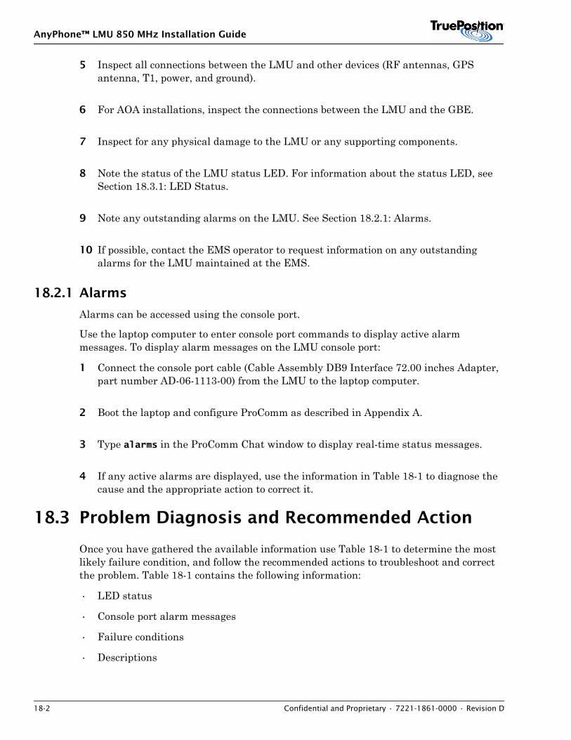
AnyPhone™ LMU 850 MHz Installation Guide
18-2 Confidential and Proprietary • 7221-1861-0000 • Revision D
5 Inspect all connections between the LMU and other devices (RF antennas, GPS antenna, T1, power, and ground).
6 For AOA installations, inspect the connections between the LMU and the GBE.
7 Inspect for any physical damage to the LMU or any supporting components.
8 Note the status of the LMU status LED. For information about the status LED, see Section 18.3.1: LED Status.
9 Note any outstanding alarms on the LMU. See Section 18.2.1: Alarms.
10 If possible, contact the EMS operator to request information on any outstanding alarms for the LMU maintained at the EMS.
18.2.1 Alarms
Alarms can be accessed using the console port.
Use the laptop computer to enter console port commands to display active alarm messages. To display alarm messages on the LMU console port:
1 Connect the console port cable (Cable Assembly DB9 Interface 72.00 inches Adapter, part number AD-06-1113-00) from the LMU to the laptop computer.
2 Boot the laptop and configure ProComm as described in Appendix A.
3 Type alarms in the ProComm Chat window to display real-time status messages.
4 If any active alarms are displayed, use the information in Table 18-1 to diagnose the cause and the appropriate action to correct it.
18.3 Problem Diagnosis and Recommended Action
Once you have gathered the available information use Table 18-1 to determine the most likely failure condition, and follow the recommended actions to troubleshoot and correct the problem. Table 18-1 contains the following information:
• LED status
• Console port alarm messages
• Failure conditions
• Descriptions
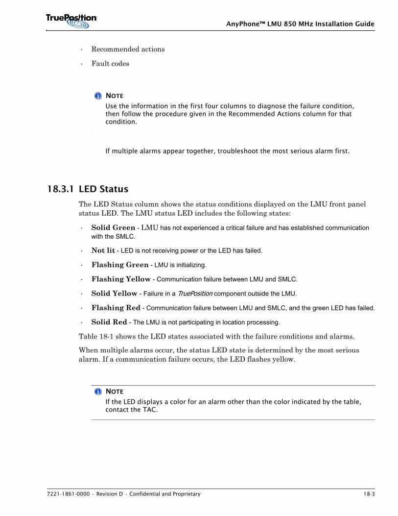
AnyPhone™ LMU 850 MHz Installation Guide
7221-1861-0000 • Revision D • Confidential and Proprietary 18-3
• Recommended actions
• Fault codes
NOTE
Use the information in the first four columns to diagnose the failure condition, then follow the procedure given in the Recommended Actions column for that condition.
If multiple alarms appear together, troubleshoot the most serious alarm first.
18.3.1 LED Status
The LED Status column shows the status conditions displayed on the LMU front panel status LED. The LMU status LED includes the following states:
• Solid Green - LMU has not experienced a critical failure and has established communication with the SMLC.
• Not lit - LED is not receiving power or the LED has failed.
• Flashing Green - LMU is initializing.
• Flashing Yellow - Communication failure between LMU and SMLC.
• Solid Yellow - Failure in a TruePosition component outside the LMU.
• Flashing Red - Communication failure between LMU and SMLC, and the green LED has failed.
• Solid Red - The LMU is not participating in location processing.
Table 18-1 shows the LED states associated with the failure conditions and alarms.
When multiple alarms occur, the status LED state is determined by the most serious alarm. If a communication failure occurs, the LED flashes yellow.
NOTE
If the LED displays a color for an alarm other than the color indicated by the table, contact the TAC.
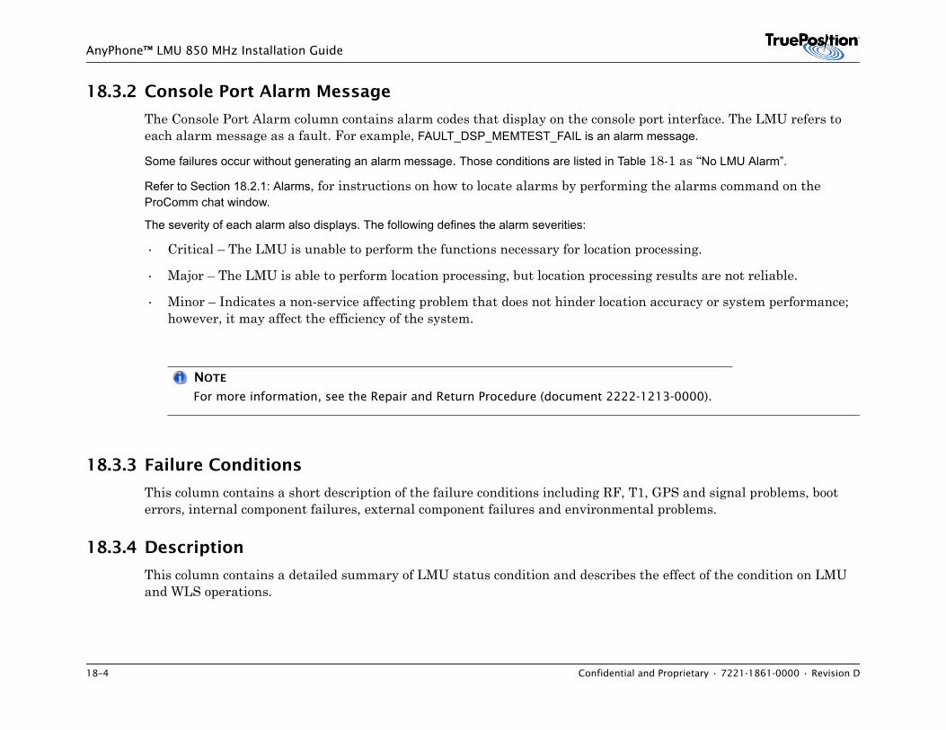
18–4 Confidential and Proprietary • 7221-1861-0000 • Revision D
AnyPhone™ LMU 850 MHz Installation Guide
18.3.2 Console Port Alarm Message
The Console Port Alarm column contains alarm codes that display on the console port interface. The LMU refers to each alarm message as a fault. For example, FAULT_DSP_MEMTEST_FAIL is an alarm message.
Some failures occur without generating an alarm message. Those conditions are listed in Table 18-1 as “No LMU Alarm”.
Refer to Section 18.2.1: Alarms, for instructions on how to locate alarms by performing the alarms command on the ProComm chat window.
The severity of each alarm also displays. The following defines the alarm severities:
• Critical – The LMU is unable to perform the functions necessary for location processing.
• Major – The LMU is able to perform location processing, but location processing results are not reliable.
• Minor – Indicates a non-service affecting problem that does not hinder location accuracy or system performance; however, it may affect the efficiency of the system.
NOTE
For more information, see the Repair and Return Procedure (document 2222-1213-0000).
18.3.3 Failure Conditions
This column contains a short description of the failure conditions including RF, T1, GPS and signal problems, boot errors, internal component failures, external component failures and environmental problems.
18.3.4 Description
This column contains a detailed summary of LMU status condition and describes the effect of the condition on LMU and WLS operations.
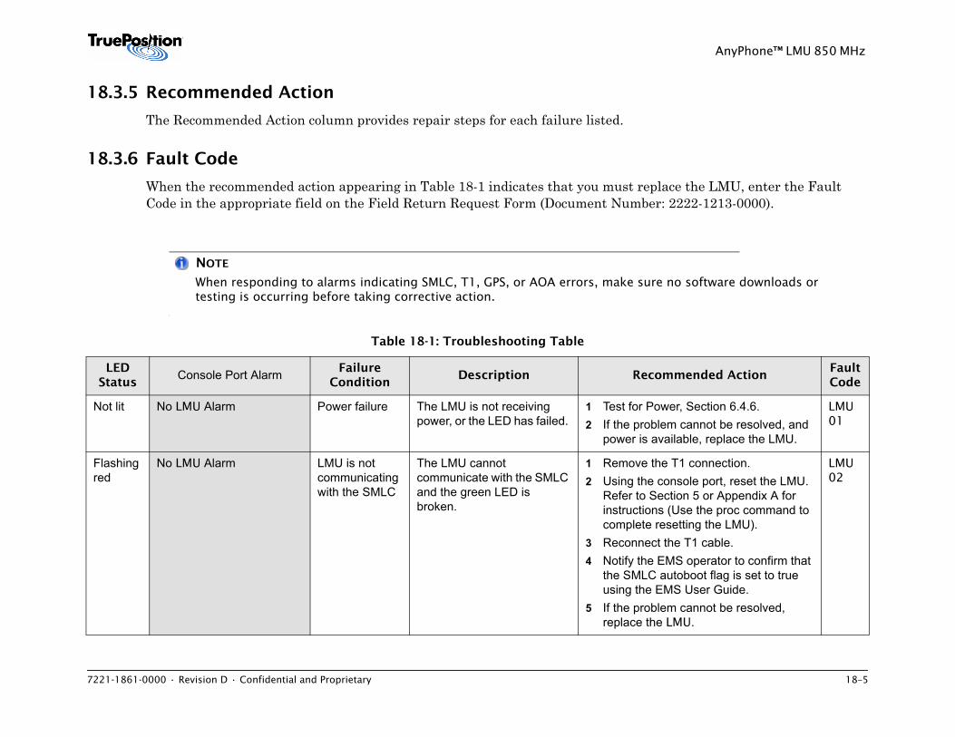
7221-1861-0000 • Revision D • Confidential and Proprietary 18–5
AnyPhone™ LMU 850 MHz
18.3.5 Recommended Action
The Recommended Action column provides repair steps for each failure listed.
18.3.6 Fault Code
When the recommended action appearing in Table 18-1 indicates that you must replace the LMU, enter the Fault Code in the appropriate field on the Field Return Request Form (Document Number: 2222-1213-0000).
NOTE
When responding to alarms indicating SMLC, T1, GPS, or AOA errors, make sure no software downloads or testing is occurring before taking corrective action.
Table 18-1: Troubleshooting Table
LED Status
Console Port Alarm Failure Condition
Description Recommended ActionFault Code
Not lit No LMU Alarm Power failure The LMU is not receiving power, or the LED has failed.
1 Test for Power, Section 6.4.6.2 If the problem cannot be resolved, and
power is available, replace the LMU.
LMU 01
Flashing red
No LMU Alarm LMU is not communicating with the SMLC
The LMU cannot communicate with the SMLC and the green LED is broken.
1 Remove the T1 connection. 2 Using the console port, reset the LMU.
Refer to Section 5 or Appendix A for instructions (Use the proc command to complete resetting the LMU).
3 Reconnect the T1 cable. 4 Notify the EMS operator to confirm that
the SMLC autoboot flag is set to true using the EMS User Guide.
5 If the problem cannot be resolved, replace the LMU.
LMU 02
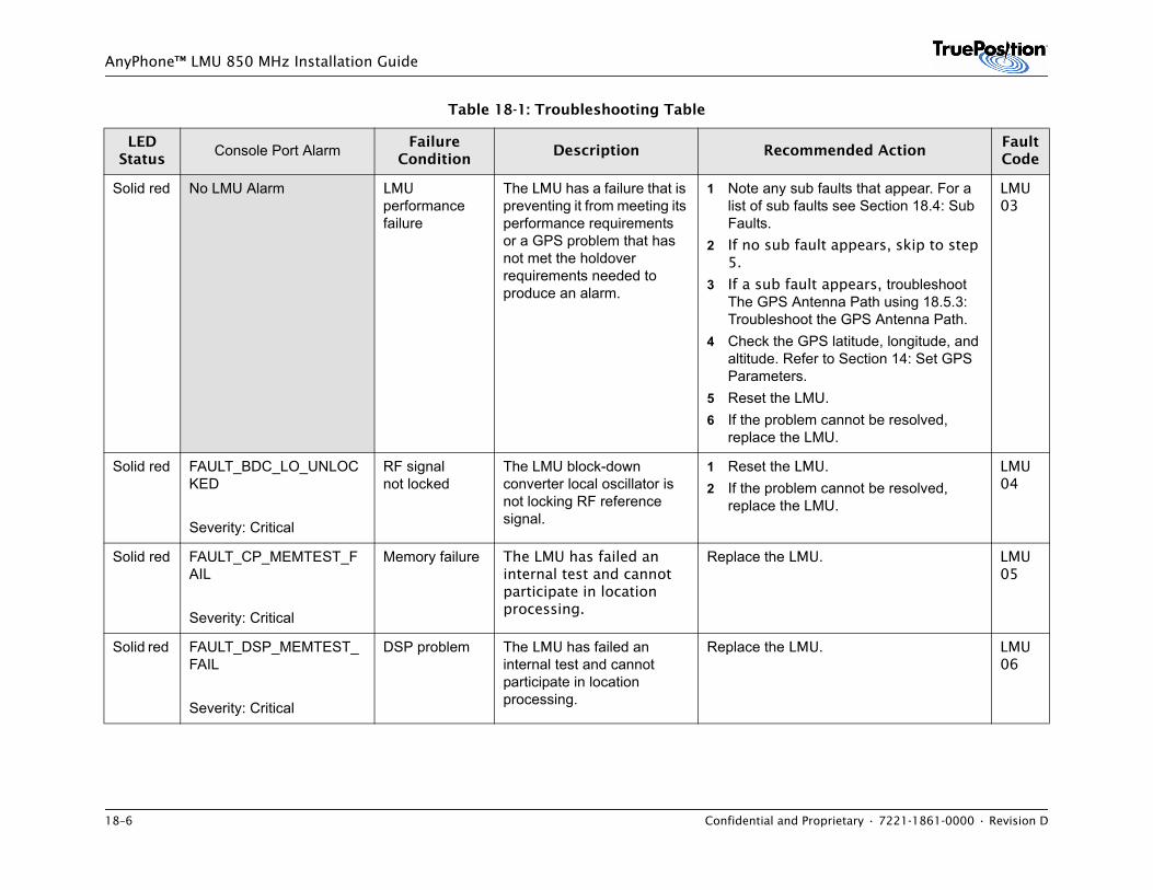
18–6 Confidential and Proprietary • 7221-1861-0000 • Revision D
AnyPhone™ LMU 850 MHz Installation Guide
Solid red No LMU Alarm LMU performance failure
The LMU has a failure that is preventing it from meeting its performance requirements or a GPS problem that has not met the holdover requirements needed to produce an alarm.
1 Note any sub faults that appear. For a list of sub faults see Section 18.4: Sub Faults.
2 If no sub fault appears, skip to step 5.
3 If a sub fault appears, troubleshoot The GPS Antenna Path using 18.5.3: Troubleshoot the GPS Antenna Path.
4 Check the GPS latitude, longitude, and altitude. Refer to Section 14: Set GPS Parameters.
5 Reset the LMU.6 If the problem cannot be resolved,
replace the LMU.
LMU 03
Solid red FAULT_BDC_LO_UNLOCKED
Severity: Critical
RF signalnot locked
The LMU block-down converter local oscillator is not locking RF reference signal.
1 Reset the LMU.2 If the problem cannot be resolved,
replace the LMU.
LMU 04
Solid red FAULT_CP_MEMTEST_FAIL
Severity: Critical
Memory failure The LMU has failed an internal test and cannot participate in location processing.
Replace the LMU. LMU 05
Solid red FAULT_DSP_MEMTEST_FAIL
Severity: Critical
DSP problem The LMU has failed an internal test and cannot participate in location processing.
Replace the LMU. LMU 06
Table 18-1: Troubleshooting Table
LED Status
Console Port Alarm Failure Condition
Description Recommended ActionFault Code
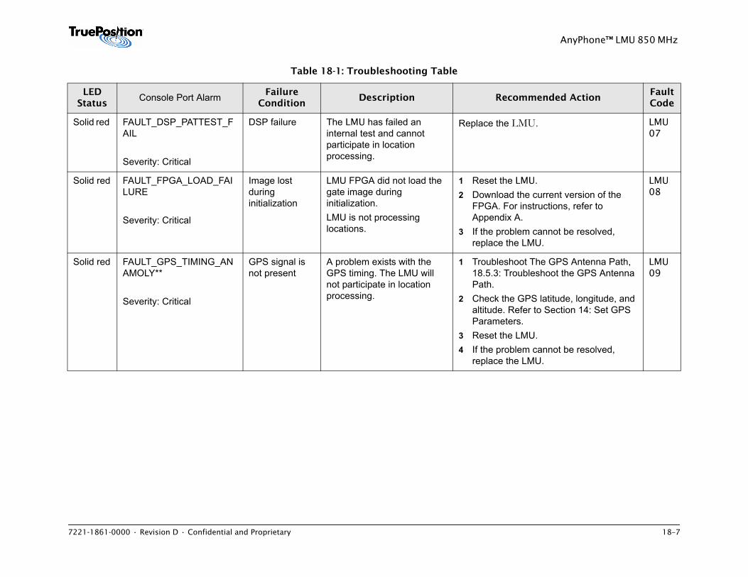
7221-1861-0000 • Revision D • Confidential and Proprietary 18–7
AnyPhone™ LMU 850 MHz
Solid red FAULT_DSP_PATTEST_FAIL
Severity: Critical
DSP failure The LMU has failed an internal test and cannot participate in location processing.
Replace the LMU. LMU 07
Solid red FAULT_FPGA_LOAD_FAILURE
Severity: Critical
Image lost during initialization
LMU FPGA did not load the gate image during initialization. LMU is not processing locations.
1 Reset the LMU. 2 Download the current version of the
FPGA. For instructions, refer to Appendix A.
3 If the problem cannot be resolved, replace the LMU.
LMU 08
Solid red FAULT_GPS_TIMING_ANAMOLY**
Severity: Critical
GPS signal is not present
A problem exists with the GPS timing. The LMU will not participate in location processing.
1 Troubleshoot The GPS Antenna Path, 18.5.3: Troubleshoot the GPS Antenna Path.
2 Check the GPS latitude, longitude, and altitude. Refer to Section 14: Set GPS Parameters.
3 Reset the LMU.4 If the problem cannot be resolved,
replace the LMU.
LMU 09
Table 18-1: Troubleshooting Table
LED Status
Console Port Alarm Failure Condition
Description Recommended ActionFault Code
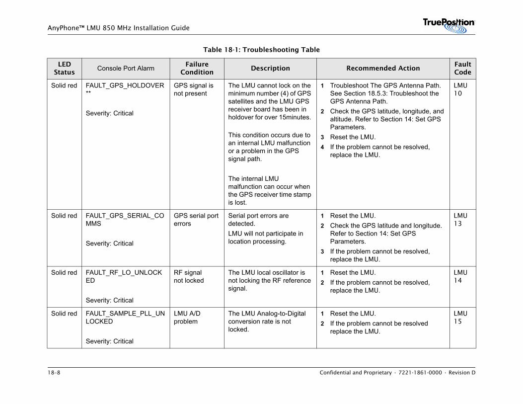
18–8 Confidential and Proprietary • 7221-1861-0000 • Revision D
AnyPhone™ LMU 850 MHz Installation Guide
Solid red FAULT_GPS_HOLDOVER**
Severity: Critical
GPS signal is not present
The LMU cannot lock on the minimum number (4) of GPS satellites and the LMU GPS receiver board has been in holdover for over 15minutes.
This condition occurs due to an internal LMU malfunction or a problem in the GPS signal path. The internal LMU malfunction can occur when the GPS receiver time stamp is lost.
1 Troubleshoot The GPS Antenna Path. See Section 18.5.3: Troubleshoot the GPS Antenna Path.
2 Check the GPS latitude, longitude, and altitude. Refer to Section 14: Set GPS Parameters.
3 Reset the LMU.4 If the problem cannot be resolved,
replace the LMU.
LMU 10
Solid red FAULT_GPS_SERIAL_COMMS
Severity: Critical
GPS serial port errors
Serial port errors are detected. LMU will not participate in location processing.
1 Reset the LMU.2 Check the GPS latitude and longitude.
Refer to Section 14: Set GPS Parameters.
3 If the problem cannot be resolved, replace the LMU.
LMU 13
Solid red FAULT_RF_LO_UNLOCKED
Severity: Critical
RF signalnot locked
The LMU local oscillator is not locking the RF reference signal.
1 Reset the LMU.2 If the problem cannot be resolved,
replace the LMU.
LMU 14
Solid red FAULT_SAMPLE_PLL_UNLOCKED
Severity: Critical
LMU A/D problem
The LMU Analog-to-Digital conversion rate is not locked.
1 Reset the LMU. 2 If the problem cannot be resolved
replace the LMU.
LMU 15
Table 18-1: Troubleshooting Table
LED Status
Console Port Alarm Failure Condition
Description Recommended ActionFault Code
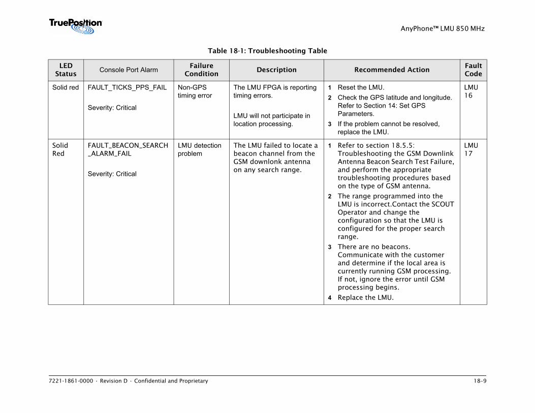
7221-1861-0000 • Revision D • Confidential and Proprietary 18–9
AnyPhone™ LMU 850 MHz
Solid red FAULT_TICKS_PPS_FAIL
Severity: Critical
Non-GPS timing error
The LMU FPGA is reporting timing errors.
LMU will not participate in location processing.
1 Reset the LMU.2 Check the GPS latitude and longitude.
Refer to Section 14: Set GPS Parameters.
3 If the problem cannot be resolved, replace the LMU.
LMU 16
Solid Red
FAULT_BEACON_SEARCH _ALARM_FAIL
Severity: Critical
LMU detection problem
The LMU failed to locate a beacon channel from the GSM downlonk antenna on any search range.
1 Refer to section 18.5.5: Troubleshooting the GSM Downlink Antenna Beacon Search Test Failure, and perform the appropriate troubleshooting procedures based on the type of GSM antenna.
2 The range programmed into the LMU is incorrect.Contact the SCOUT Operator and change the configuration so that the LMU is configured for the proper search range.
3 There are no beacons. Communicate with the customer and determine if the local area is currently running GSM processing. If not, ignore the error until GSM processing begins.
4 Replace the LMU.
LMU 17
Table 18-1: Troubleshooting Table
LED Status
Console Port Alarm Failure Condition
Description Recommended ActionFault Code
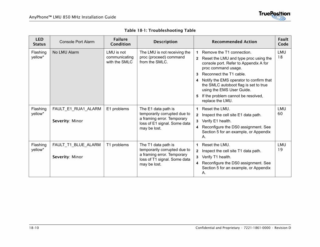
18–10 Confidential and Proprietary • 7221-1861-0000 • Revision D
AnyPhone™ LMU 850 MHz Installation Guide
Flashing yellow*
No LMU Alarm LMU is not communicating with the SMLC
The LMU is not receiving the proc (proceed) command from the SMLC.
1 Remove the T1 connection. 2 Reset the LMU and type proc using the
console port. Refer to Appendix A for proc command usage.
3 Reconnect the T1 cable. 4 Notify the EMS operator to confirm that
the SMLC autoboot flag is set to true using the EMS User Guide.
5 If the problem cannot be resolved, replace the LMU.
LMU 18
Flashing yellow*
FAULT_E1_RUA1_ALARM
Severity: Minor
E1 problems The E1 data path is temporarily corrupted due to a framing error. Temporary loss of E1 signal. Some data may be lost.
1 Reset the LMU.2 Inspect the cell site E1 data path.3 Verify E1 health.4 Reconfigure the DS0 assignment. See
Section 5 for an example, or Appendix A.
LMU 60
Flashing yellow*
FAULT_T1_BLUE_ALARM
Severity: Minor
T1 problems The T1 data path is temporarily corrupted due to a framing error. Temporary loss of T1 signal. Some data may be lost.
1 Reset the LMU.2 Inspect the cell site T1 data path.3 Verify T1 health.4 Reconfigure the DS0 assignment. See
Section 5 for an example, or Appendix A.
LMU 19
Table 18-1: Troubleshooting Table
LED Status
Console Port Alarm Failure Condition
Description Recommended ActionFault Code
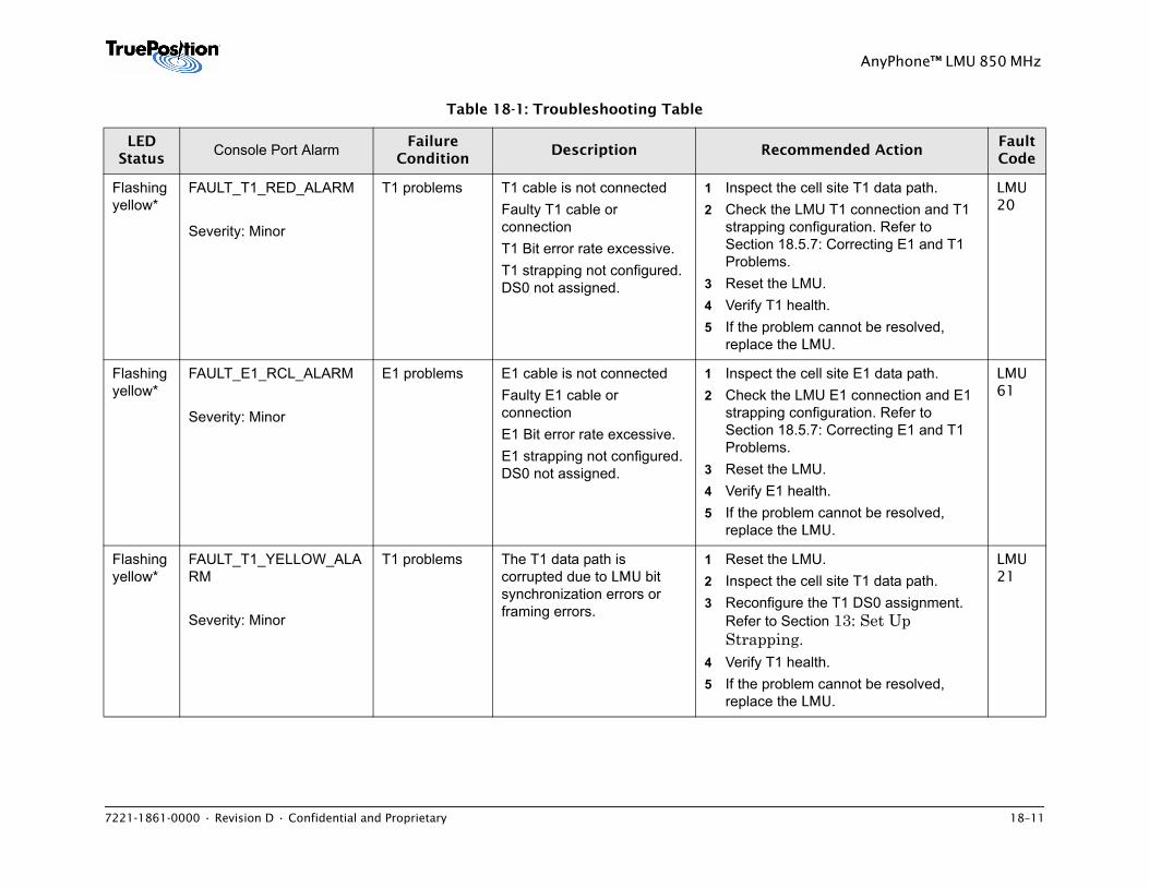
7221-1861-0000 • Revision D • Confidential and Proprietary 18–11
AnyPhone™ LMU 850 MHz
Flashing yellow*
FAULT_T1_RED_ALARM
Severity: Minor
T1 problems T1 cable is not connectedFaulty T1 cable or connectionT1 Bit error rate excessive.T1 strapping not configured. DS0 not assigned.
1 Inspect the cell site T1 data path.2 Check the LMU T1 connection and T1
strapping configuration. Refer to Section 18.5.7: Correcting E1 and T1 Problems.
3 Reset the LMU.4 Verify T1 health.5 If the problem cannot be resolved,
replace the LMU.
LMU 20
Flashing yellow*
FAULT_E1_RCL_ALARM
Severity: Minor
E1 problems E1 cable is not connectedFaulty E1 cable or connectionE1 Bit error rate excessive.E1 strapping not configured. DS0 not assigned.
1 Inspect the cell site E1 data path.2 Check the LMU E1 connection and E1
strapping configuration. Refer to Section 18.5.7: Correcting E1 and T1 Problems.
3 Reset the LMU.4 Verify E1 health.5 If the problem cannot be resolved,
replace the LMU.
LMU 61
Flashing yellow*
FAULT_T1_YELLOW_ALARM
Severity: Minor
T1 problems The T1 data path is corrupted due to LMU bit synchronization errors or framing errors.
1 Reset the LMU.2 Inspect the cell site T1 data path.3 Reconfigure the T1 DS0 assignment.
Refer to Section 13: Set Up Strapping.
4 Verify T1 health.5 If the problem cannot be resolved,
replace the LMU.
LMU 21
Table 18-1: Troubleshooting Table
LED Status
Console Port Alarm Failure Condition
Description Recommended ActionFault Code
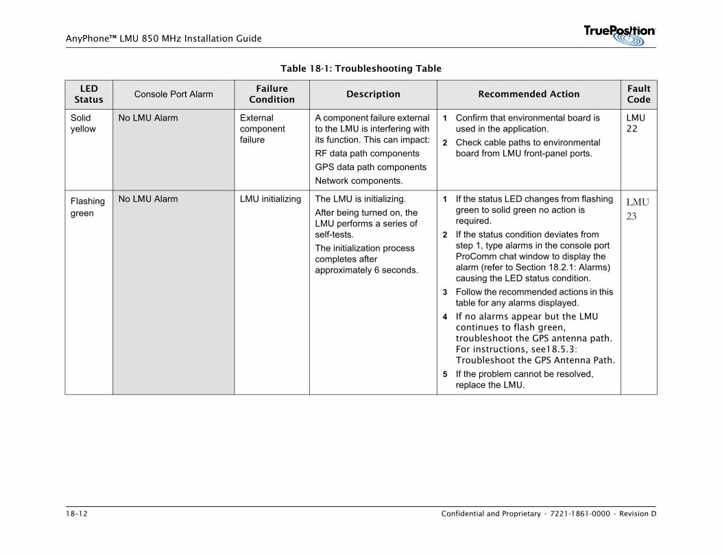
18–12 Confidential and Proprietary • 7221-1861-0000 • Revision D
AnyPhone™ LMU 850 MHz Installation Guide
Solid yellow
No LMU Alarm External component failure
A component failure external to the LMU is interfering with its function. This can impact:RF data path componentsGPS data path componentsNetwork components.
1 Confirm that environmental board is used in the application.
2 Check cable paths to environmental board from LMU front-panel ports.
LMU 22
Flashing green
No LMU Alarm LMU initializing The LMU is initializing. After being turned on, the LMU performs a series of self-tests. The initialization process completes after approximately 6 seconds.
1 If the status LED changes from flashing green to solid green no action is required.
2 If the status condition deviates from step 1, type alarms in the console port ProComm chat window to display the alarm (refer to Section 18.2.1: Alarms) causing the LED status condition.
3 Follow the recommended actions in this table for any alarms displayed.
4 If no alarms appear but the LMU continues to flash green, troubleshoot the GPS antenna path. For instructions, see18.5.3: Troubleshoot the GPS Antenna Path.
5 If the problem cannot be resolved, replace the LMU.
LMU 23
Table 18-1: Troubleshooting Table
LED Status
Console Port Alarm Failure Condition
Description Recommended ActionFault Code
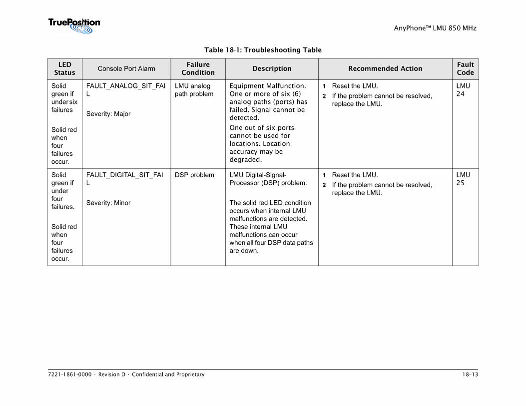
7221-1861-0000 • Revision D • Confidential and Proprietary 18–13
AnyPhone™ LMU 850 MHz
Solid green if under six failures
Solid red when four failures occur.
FAULT_ANALOG_SIT_FAIL
Severity: Major
LMU analog path problem
Equipment Malfunction. One or more of six (6) analog paths (ports) has failed. Signal cannot be detected.
One out of six ports cannot be used for locations. Location accuracy may be degraded.
1 Reset the LMU.2 If the problem cannot be resolved,
replace the LMU.
LMU 24
Solid green if under four failures.
Solid red when four failures occur.
FAULT_DIGITAL_SIT_FAIL
Severity: Minor
DSP problem LMU Digital-Signal- Processor (DSP) problem.
The solid red LED condition occurs when internal LMU malfunctions are detected. These internal LMU malfunctions can occur when all four DSP data paths are down.
1 Reset the LMU.2 If the problem cannot be resolved,
replace the LMU.
LMU 25
Table 18-1: Troubleshooting Table
LED Status
Console Port Alarm Failure Condition
Description Recommended ActionFault Code
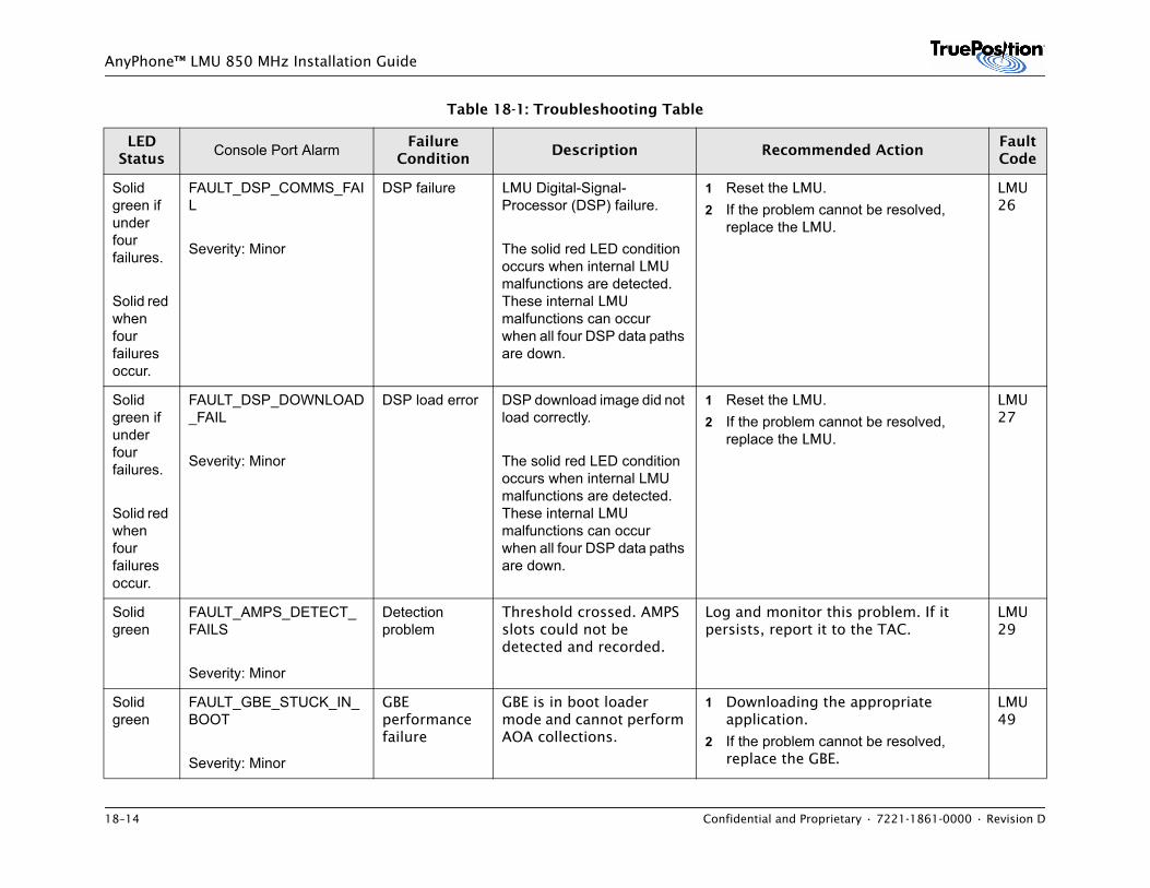
18–14 Confidential and Proprietary • 7221-1861-0000 • Revision D
AnyPhone™ LMU 850 MHz Installation Guide
Solid green if under four failures.
Solid red when four failures occur.
FAULT_DSP_COMMS_FAIL
Severity: Minor
DSP failure LMU Digital-Signal- Processor (DSP) failure.
The solid red LED condition occurs when internal LMU malfunctions are detected. These internal LMU malfunctions can occur when all four DSP data paths are down.
1 Reset the LMU. 2 If the problem cannot be resolved,
replace the LMU.
LMU 26
Solid green if under four failures.
Solid red when four failures occur.
FAULT_DSP_DOWNLOAD_FAIL
Severity: Minor
DSP load error DSP download image did not load correctly.
The solid red LED condition occurs when internal LMU malfunctions are detected. These internal LMU malfunctions can occur when all four DSP data paths are down.
1 Reset the LMU.2 If the problem cannot be resolved,
replace the LMU.
LMU 27
Solid green
FAULT_AMPS_DETECT_FAILS
Severity: Minor
Detection problem
Threshold crossed. AMPS slots could not be detected and recorded.
Log and monitor this problem. If it persists, report it to the TAC.
LMU 29
Solid green
FAULT_GBE_STUCK_IN_BOOT
Severity: Minor
GBE performance failure
GBE is in boot loader mode and cannot perform AOA collections.
1 Downloading the appropriate application.
2 If the problem cannot be resolved, replace the GBE.
LMU 49
Table 18-1: Troubleshooting Table
LED Status
Console Port Alarm Failure Condition
Description Recommended ActionFault Code
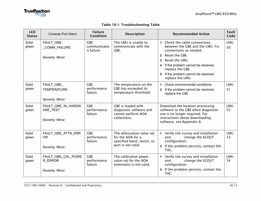
7221-1861-0000 • Revision D • Confidential and Proprietary 18–15
AnyPhone™ LMU 850 MHz
Solid green
FAULT_GBE_COMM_FAILURE
Severity: Minor
GBE communication failure
The LMU is unable to communicate with the GBE.
1 Check the cable connections between the GBE and the LMU. Fix connections as needed.
2 Reset the GBE.
3 Reset the LMU.
4 If the problem cannot be resolved, replace the GBE.
5 If the problem cannot be resolved, replace the LMU.
LMU
50
Solid green
FAULT_GBE_TEMPERATURE
Severity: Minor
GBE performance failure
The temperature on the GBE has exceeded its temperature threshold.
1 Check environmental conditions. 2 If the problem cannot be resolved,
replace the GBE.
LMU
51
Solid green
FAULT_GBE_IN_HARDWARE_TEST
Severity: Minor
GBE performance failure
GBE is loaded with diagnostic software and cannot perform AOA collections.
Download the location processing software to the GBE when diagnostic use is no longer required. For instructions about downloading software, see Appendix A.
LMU 52
Solid green
FAULT_GBE_ATTN_ERROR
Severity: Minor
GBE performance failure
The attenuation value set for the AOA for a specified band, sector, or port is not valid.
1 Verify site survey and installation and change the SCOUT configuration.
2 If the problem persists, contact the TAC.
LMU 53
Solid green
FAULT_GBE_CAL_POWER_ERROR
Severity: Minor
GBE performance failure
The calibration power value set for the AOA antenna(s) is not valid.
1 Verify site survey and installation and change the SCOUT configuration.
2 If the problem persists, contact the TAC.
LMU 54
Table 18-1: Troubleshooting Table
LED Status
Console Port Alarm Failure Condition
Description Recommended ActionFault Code
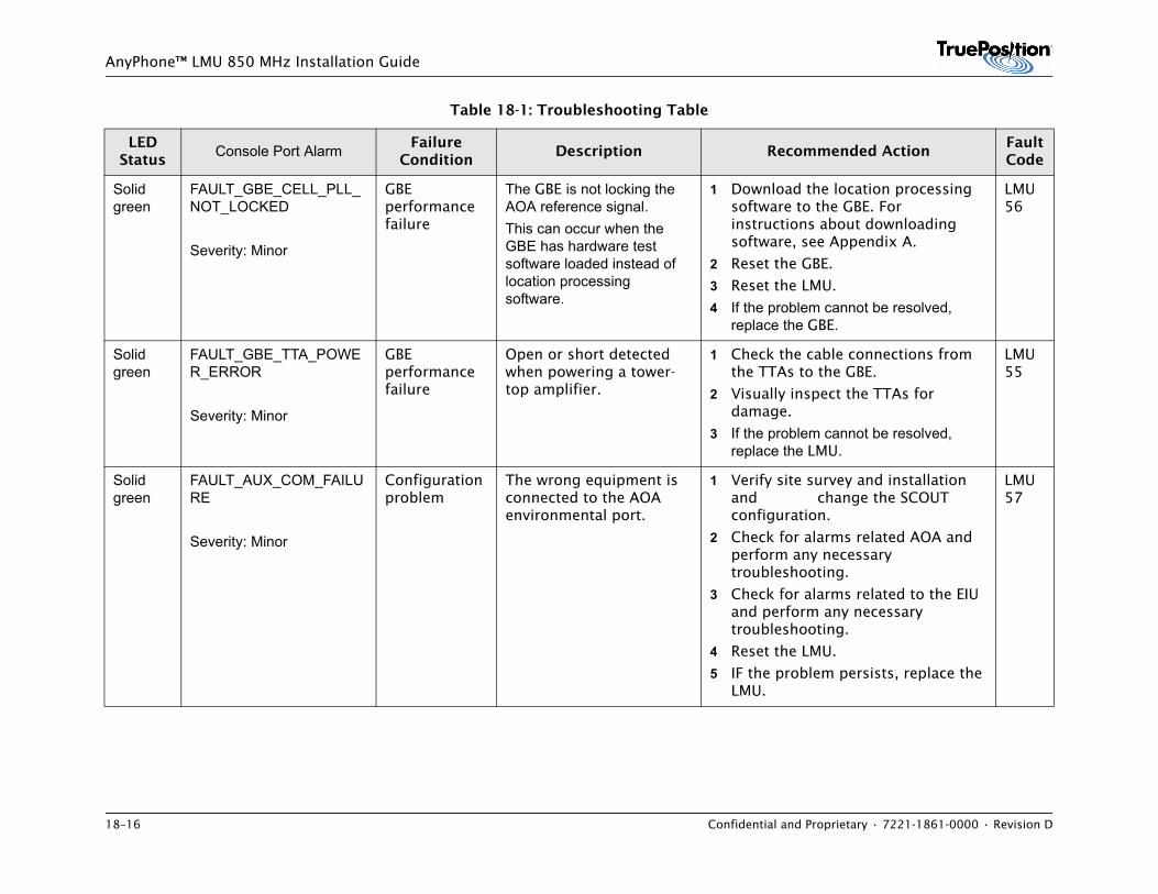
18–16 Confidential and Proprietary • 7221-1861-0000 • Revision D
AnyPhone™ LMU 850 MHz Installation Guide
Solid green
FAULT_GBE_CELL_PLL_NOT_LOCKED
Severity: Minor
GBE performance failure
The GBE is not locking the AOA reference signal. This can occur when the GBE has hardware test software loaded instead of location processing software.
1 Download the location processing software to the GBE. For instructions about downloading software, see Appendix A.
2 Reset the GBE.
3 Reset the LMU.
4 If the problem cannot be resolved, replace the GBE.
LMU 56
Solid green
FAULT_GBE_TTA_POWER_ERROR
Severity: Minor
GBE performance failure
Open or short detected when powering a tower-top amplifier.
1 Check the cable connections from the TTAs to the GBE.
2 Visually inspect the TTAs for damage.
3 If the problem cannot be resolved, replace the LMU.
LMU 55
Solid green
FAULT_AUX_COM_FAILURE
Severity: Minor
Configuration problem
The wrong equipment is connected to the AOA environmental port.
1 Verify site survey and installation and change the SCOUT configuration.
2 Check for alarms related AOA and perform any necessary troubleshooting.
3 Check for alarms related to the EIU and perform any necessary troubleshooting.
4 Reset the LMU.
5 IF the problem persists, replace the LMU.
LMU 57
Table 18-1: Troubleshooting Table
LED Status
Console Port Alarm Failure Condition
Description Recommended ActionFault Code
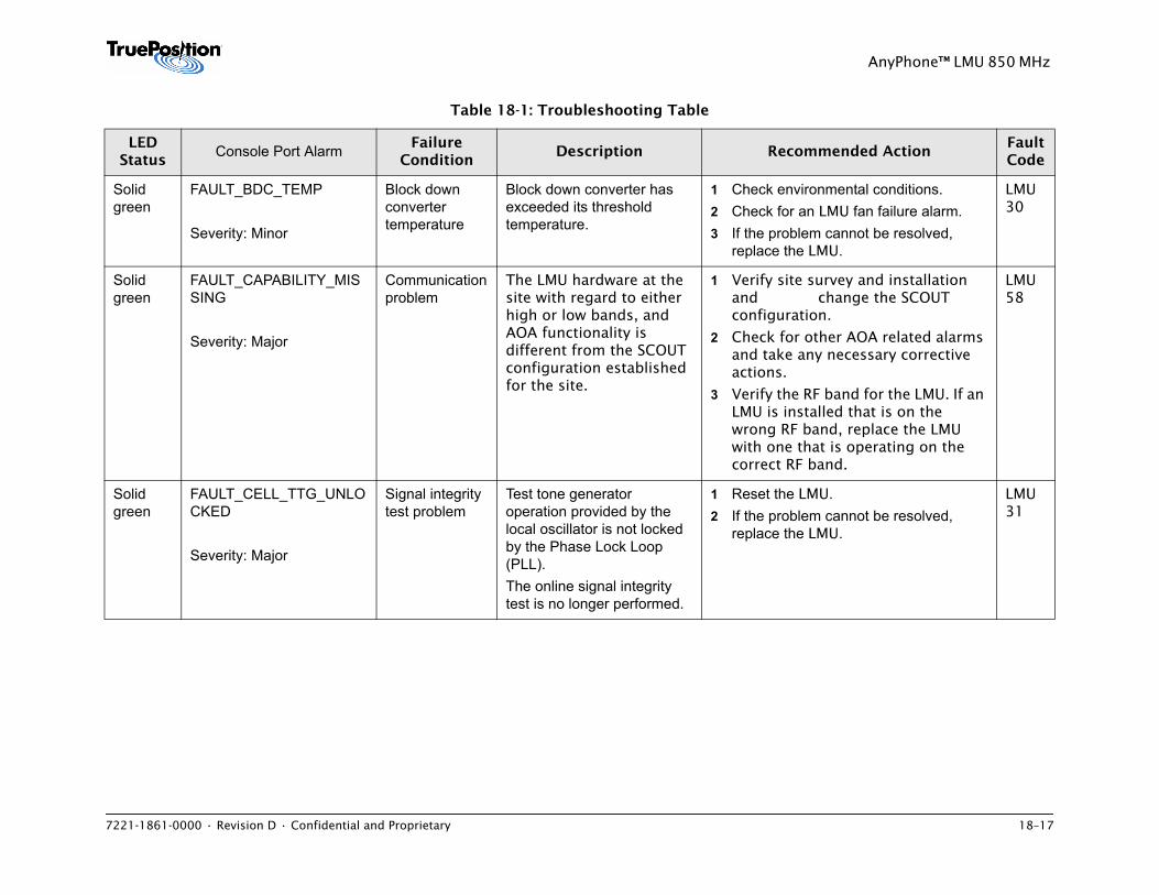
7221-1861-0000 • Revision D • Confidential and Proprietary 18–17
AnyPhone™ LMU 850 MHz
Solid green
FAULT_BDC_TEMP
Severity: Minor
Block down converter temperature
Block down converter has exceeded its threshold temperature.
1 Check environmental conditions. 2 Check for an LMU fan failure alarm.3 If the problem cannot be resolved,
replace the LMU.
LMU 30
Solid green
FAULT_CAPABILITY_MISSING
Severity: Major
Communication problem
The LMU hardware at the site with regard to either high or low bands, and AOA functionality is different from the SCOUT configuration established for the site.
1 Verify site survey and installation and change the SCOUT configuration.
2 Check for other AOA related alarms and take any necessary corrective actions.
3 Verify the RF band for the LMU. If an LMU is installed that is on the wrong RF band, replace the LMU with one that is operating on the correct RF band.
LMU 58
Solid green
FAULT_CELL_TTG_UNLOCKED
Severity: Major
Signal integrity test problem
Test tone generator operation provided by the local oscillator is not locked by the Phase Lock Loop (PLL). The online signal integrity test is no longer performed.
1 Reset the LMU. 2 If the problem cannot be resolved,
replace the LMU.
LMU 31
Table 18-1: Troubleshooting Table
LED Status
Console Port Alarm Failure Condition
Description Recommended ActionFault Code
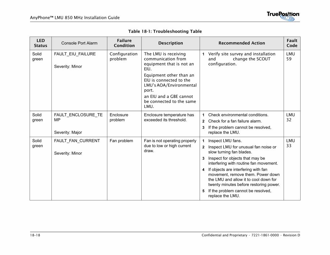
18–18 Confidential and Proprietary • 7221-1861-0000 • Revision D
AnyPhone™ LMU 850 MHz Installation Guide
Solid green
FAULT_EIU_FAILURE
Severity: Minor
Configuration problem
The LMU is receiving communication from equipment that is not an EIU.
Equipment other than an EIU is connected to the LMU’s AOA/Environmental port.
an EIU and a GBE cannot be connected to the same LMU.
1 Verify site survey and installation and change the SCOUT configuration.
LMU 59
Solid green
FAULT_ENCLOSURE_TEMP
Severity: Major
Enclosure problem
Enclosure temperature has exceeded its threshold.
1 Check environmental conditions. 2 Check for a fan failure alarm. 3 If the problem cannot be resolved,
replace the LMU.
LMU 32
Solid green
FAULT_FAN_CURRENT
Severity: Minor
Fan problem Fan is not operating properly due to low or high current draw.
1 Inspect LMU fans. 2 Inspect LMU for unusual fan noise or
slow turning fan blades. 3 Inspect for objects that may be
interfering with routine fan movement. 4 If objects are interfering with fan
movement, remove them. Power down the LMU and allow it to cool down for twenty minutes before restoring power.
5 If the problem cannot be resolved, replace the LMU.
LMU 33
Table 18-1: Troubleshooting Table
LED Status
Console Port Alarm Failure Condition
Description Recommended ActionFault Code
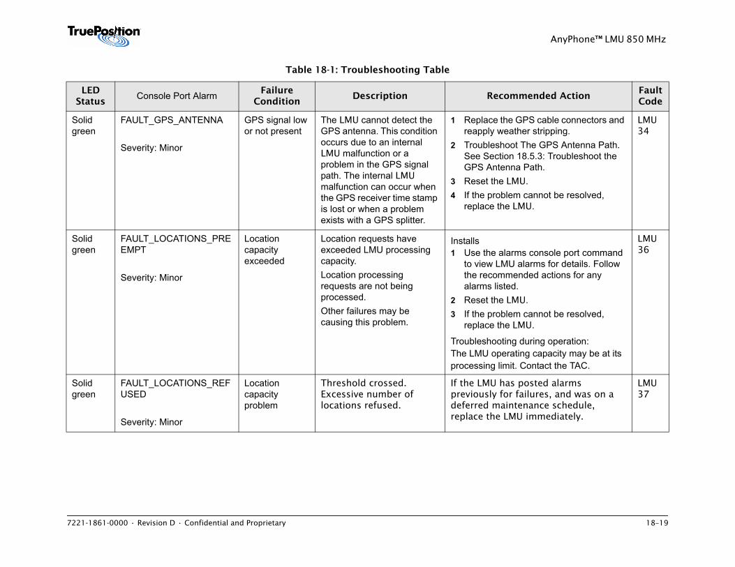
7221-1861-0000 • Revision D • Confidential and Proprietary 18–19
AnyPhone™ LMU 850 MHz
Solid green
FAULT_GPS_ANTENNA
Severity: Minor
GPS signal low or not present
The LMU cannot detect the GPS antenna. This condition occurs due to an internal LMU malfunction or a problem in the GPS signal path. The internal LMU malfunction can occur when the GPS receiver time stamp is lost or when a problem exists with a GPS splitter.
1 Replace the GPS cable connectors and reapply weather stripping.
2 Troubleshoot The GPS Antenna Path. See Section 18.5.3: Troubleshoot the GPS Antenna Path.
3 Reset the LMU.4 If the problem cannot be resolved,
replace the LMU.
LMU 34
Solid green
FAULT_LOCATIONS_PREEMPT
Severity: Minor
Location capacity exceeded
Location requests have exceeded LMU processing capacity.Location processing requests are not being processed. Other failures may be causing this problem.
Installs1 Use the alarms console port command
to view LMU alarms for details. Follow the recommended actions for any alarms listed.
2 Reset the LMU. 3 If the problem cannot be resolved,
replace the LMU.
Troubleshooting during operation:The LMU operating capacity may be at its processing limit. Contact the TAC.
LMU 36
Solid green
FAULT_LOCATIONS_REFUSED
Severity: Minor
Location capacity problem
Threshold crossed. Excessive number of locations refused.
If the LMU has posted alarms previously for failures, and was on a deferred maintenance schedule, replace the LMU immediately.
LMU 37
Table 18-1: Troubleshooting Table
LED Status
Console Port Alarm Failure Condition
Description Recommended ActionFault Code
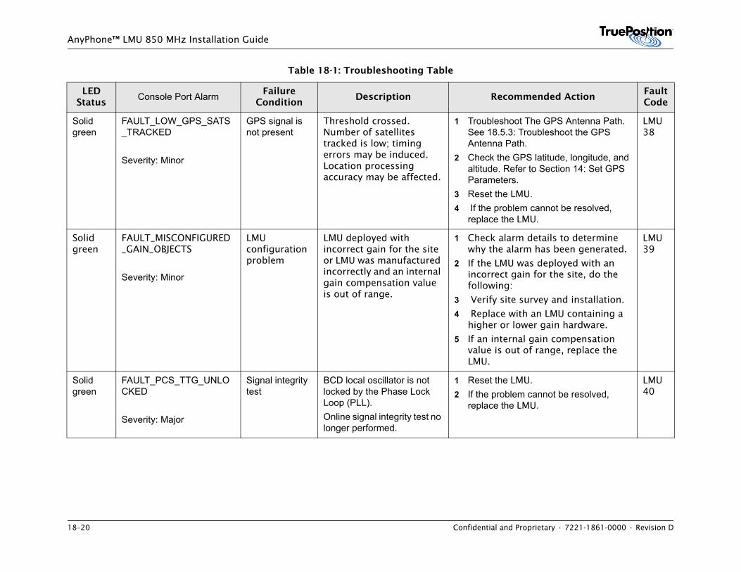
18–20 Confidential and Proprietary • 7221-1861-0000 • Revision D
AnyPhone™ LMU 850 MHz Installation Guide
Solid green
FAULT_LOW_GPS_SATS_TRACKED
Severity: Minor
GPS signal is not present
Threshold crossed. Number of satellites tracked is low; timing errors may be induced. Location processing accuracy may be affected.
1 Troubleshoot The GPS Antenna Path. See 18.5.3: Troubleshoot the GPS Antenna Path.
2 Check the GPS latitude, longitude, and altitude. Refer to Section 14: Set GPS Parameters.
3 Reset the LMU.4 If the problem cannot be resolved,
replace the LMU.
LMU 38
Solid green
FAULT_MISCONFIGURED_GAIN_OBJECTS
Severity: Minor
LMU configuration problem
LMU deployed with incorrect gain for the site or LMU was manufactured incorrectly and an internal gain compensation value is out of range.
1 Check alarm details to determine why the alarm has been generated.
2 If the LMU was deployed with an incorrect gain for the site, do the following:
3 Verify site survey and installation.
4 Replace with an LMU containing a higher or lower gain hardware.
5 If an internal gain compensation value is out of range, replace the LMU.
LMU 39
Solid green
FAULT_PCS_TTG_UNLOCKED
Severity: Major
Signal integrity test
BCD local oscillator is not locked by the Phase Lock Loop (PLL). Online signal integrity test no longer performed.
1 Reset the LMU. 2 If the problem cannot be resolved,
replace the LMU.
LMU 40
Table 18-1: Troubleshooting Table
LED Status
Console Port Alarm Failure Condition
Description Recommended ActionFault Code
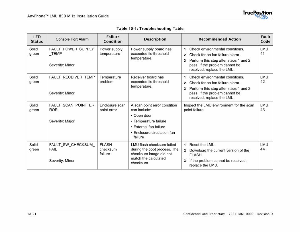
18–21 Confidential and Proprietary • 7221-1861-0000 • Revision D
AnyPhone™ LMU 850 MHz Installation Guide
Solid green
FAULT_POWER_SUPPLY_TEMP
Severity: Minor
Power supply temperature
Power supply board has exceeded its threshold temperature.
1 Check environmental conditions. 2 Check for an fan failure alarm. 3 Perform this step after steps 1 and 2
pass. If the problem cannot be resolved, replace the LMU.
LMU 41
Solid green
FAULT_RECEIVER_TEMP
Severity: Minor
Temperature problem
Receiver board has exceeded its threshold temperature.
1 Check environmental conditions. 2 Check for an fan failure alarm. 3 Perform this step after steps 1 and 2
pass. If the problem cannot be resolved, replace the LMU.
LMU 42
Solid green
FAULT_SCAN_POINT_ERROR
Severity: Major
Enclosure scan point error
A scan point error condition can include:• Open door• Temperature failure• External fan failure• Enclosure circulation fan
failure
Inspect the LMU environment for the scan point failure.
LMU 43
Solid green
FAULT_SW_CHECKSUM_FAIL
Severity: Minor
FLASH checksum failure
LMU flash checksum failed during the boot process. The checksum image did not match the calculated checksum.
1 Reset the LMU. 2 Download the current version of the
FLASH.3 If the problem cannot be resolved,
replace the LMU.
LMU 44
Table 18-1: Troubleshooting Table
LED Status
Console Port Alarm Failure Condition
Description Recommended ActionFault Code
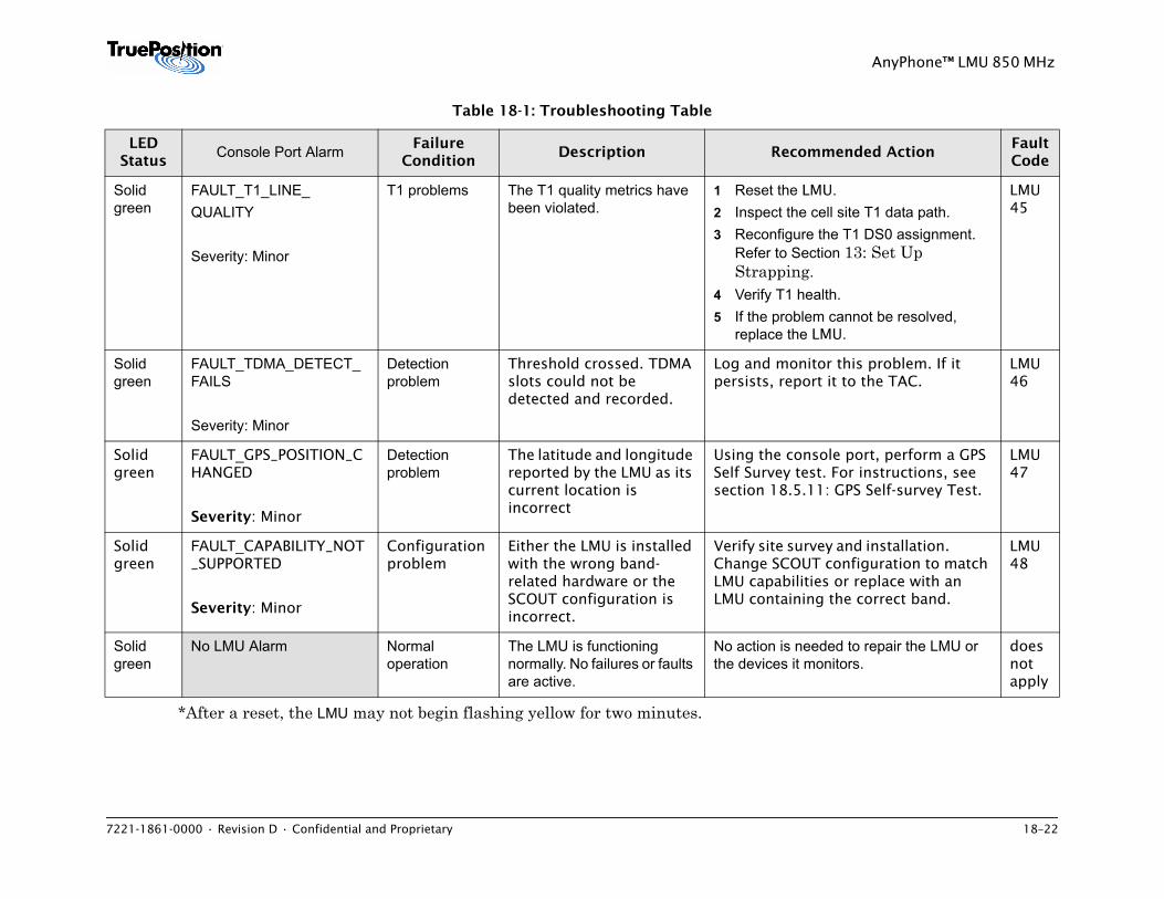
7221-1861-0000 • Revision D • Confidential and Proprietary 18–22
AnyPhone™ LMU 850 MHz
*After a reset, the LMU may not begin flashing yellow for two minutes.
Solid green
FAULT_T1_LINE_QUALITY
Severity: Minor
T1 problems The T1 quality metrics have been violated.
1 Reset the LMU.2 Inspect the cell site T1 data path.3 Reconfigure the T1 DS0 assignment.
Refer to Section 13: Set Up Strapping.
4 Verify T1 health.5 If the problem cannot be resolved,
replace the LMU.
LMU 45
Solid green
FAULT_TDMA_DETECT_FAILS
Severity: Minor
Detection problem
Threshold crossed. TDMA slots could not be detected and recorded.
Log and monitor this problem. If it persists, report it to the TAC.
LMU 46
Solid green
FAULT_GPS_POSITION_CHANGED
Severity: Minor
Detection problem
The latitude and longitude reported by the LMU as its current location is incorrect
Using the console port, perform a GPS Self Survey test. For instructions, see section 18.5.11: GPS Self-survey Test.
LMU 47
Solid green
FAULT_CAPABILITY_NOT_SUPPORTED
Severity: Minor
Configuration problem
Either the LMU is installed with the wrong band-related hardware or the SCOUT configuration is incorrect.
Verify site survey and installation. Change SCOUT configuration to match LMU capabilities or replace with an LMU containing the correct band.
LMU 48
Solid green
No LMU Alarm Normal operation
The LMU is functioning normally. No failures or faults are active.
No action is needed to repair the LMU or the devices it monitors.
does not apply
Table 18-1: Troubleshooting Table
LED Status
Console Port Alarm Failure Condition
Description Recommended ActionFault Code
18–23 Confidential and Proprietary • 7221-1861-0000 • Revision D
AnyPhone™ LMU 850 MHz Installation Guide
18.4 Sub Faults
After entering the Alarms command, SUBFAULT messages may display with the GPS TIMING ANAMOLY alarm or when no fault appears and the Status LED on the LMU is solid red. When a sub fault appears, take the recommended actions associated with the GPS TIMING ANAMOLY. The following is a list of the sub faults:
• SUBFAULT_GPS_FAIL_LOW_TFOM
• SUBFAULT_GPS_FAIL_ONE_PPS
• SUBFAULT_GPS_FAIL_TEN_MHZ
• SUBFAULT_GPSRA_FAIL_TICKS_3MHZ
• SUBFAULT_DATUM_ROM_CSUM_ERROR
• SUBFAULT_DATUM_RAM_CHECK_FAIL
• SUBFAULT_DATUM_FPGA_CHECK_FAIL
• SUBFAULT_DATUM_POWER_SUPPLY_FAIL
• SUBFAULT_DATUM_OSC_VLTG_AT_RAIL
• SUBFAULT_ZYFER_GPS_TIME_INVALID
• SUBFAULT_ZYFER_DAC_OUT_OF_RANGE
• SUBFAULT_ZYFER_OSCILLATOR_FAULT
18.5 Troubleshooting Procedures
Perform the procedures in this section as indicated by the Recommended Actions in Table 18-1.
AnyPhone™ LMU 850 MHz Installation Guide
18-24 Confidential and Proprietary • 7221-1861-0000 • Revision D
18.5.1 Troubleshoot the Uplink RF Ports
Read this section to determine whether an RF uplink port on the LMU or the multicoupler has failed, or if a cable failed.
This test swaps an RF cable between ports to identify cable and port integrity. The test recommends moving a cable from a suspect bad port (A) to a known good port (B). Known good ports are those that pass the RF signal tests described in Section 16, Test RF Signals.
To troubleshoot LMU RF uplink ports:
1 Swap the cable from the LMU RF uplink port with no signal (A) to a known good RF uplink port (B).
2 Perform an RF signal test on port (B) using the procedures described in Section Test RF Signals. If an RF signal is not present on the port, refer to 18.5.2: Check Faulty RF Cable.
3 If the RF signal is not present on port (B) in step 2 and the cable is good, the port on the multi-coupler has failed. Report this result to the carrier.
4 If the RF signal is present on the port (B) in step 2, reset the LMU.
a) If the LMU does not have a T1 connection, the startup process will stop and wait for input.
b) Type proc and press R to allow the LMU to continue. The proc command is not visible on the terminal screen when you type it.
5 Re-connect the cable to the original port (A).
6 Perform an RF signal test on port (A) using the procedures described in Section 7.8 Test RF Signals. If an RF signal is not present on the port, replace the LMU.
Evaluating Results
If only one LMU RF port fails, replace the LMU.
If a port on the multicoupler fails, contact the carrier.
If all or most of the ports fail, test the RF cables. For instructions, see 18.5.2: Check Faulty RF Cable.
If the cabling is correct, the LMU was deployed with an incorrect gain for the site. Do the following:
• Verify site survey and installation.
AnyPhone™ LMU 850 MHz Installation Guide
7221-1861-0000 • Revision D • Confidential and Proprietary 18-25
• Replace with an LMU containing the appropriate higher or lower gain hardware.
NOTE
When returning an LMU to TruePosition, complete the following steps:
1. Note the appropriate alarm on the ProComm window.
2. Refer to the Fault Codes column in Table 18-1 for the fault code associated with the specific alarm.
For example, alarm FAULT_MISCONFIGURED_GAIN_OBJECTS corresponds to fault code LMU 45.
3. Enter the appropriate fault code on the Field Return Request Form.
NOTE
If the RF problem cannot be isolated in the LMU or cable report the problem to the carrier and indicate that an RF problem exists at the base station. Do not replace the LMU.
18.5.2 Check Faulty RF Cable
To test a faulty RF cable:
1 Test cable with volt-ohm meter. Look for open circuit or short circuit. Normal readings for an antenna is 60 to 100 ohms:
– Center pin to shield should be infinite resistance indicating an open circuit
– center pin to center pin (end to end) should be two to three ohms indicating a short
2 Use the Sitemaster to sweep the cable to locate the fault. A fault is detected when the test result exceeds 1:1.3 VSWR.
3 Remove and replace faulty connectors or cables as needed.
18.5.3 Troubleshoot the GPS Antenna Path
This procedure describes how to test the path between the GPS port and the GPS antenna using a Trimble unit. It uses a process of elimination to test the path from the LMU to the GPS antenna by eliminating one component at a time until the entire path is tested. If the Trimble unit locates 3 or fewer satellites, there is a failed component in the path. Each
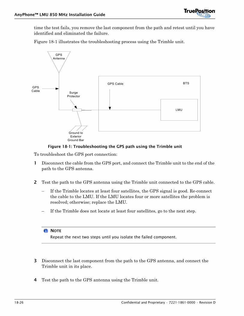
AnyPhone™ LMU 850 MHz Installation Guide
18-26 Confidential and Proprietary • 7221-1861-0000 • Revision D
time the test fails, you remove the last component from the path and retest until you have identified and eliminated the failure.
Figure 18-1 illustrates the troubleshooting process using the Trimble unit.
Figure 18-1: Troubleshooting the GPS path using the Trimble unit
To troubleshoot the GPS port connection:
1 Disconnect the cable from the GPS port, and connect the Trimble unit to the end of the path to the GPS antenna.
2 Test the path to the GPS antenna using the Trimble unit connected to the GPS cable.
– If the Trimble locates at least four satellites, the GPS signal is good. Re-connect the cable to the LMU. If the LMU locates four or more satellites the problem is resolved; otherwise; replace the LMU.
– If the Trimble does not locate at least four satellites, go to the next step.
NOTE
Repeat the next two steps until you isolate the failed component.
3 Disconnect the last component from the path to the GPS antenna, and connect the Trimble unit in its place.
4 Test the path to the GPS antenna using the Trimble unit.
GPSAntenna
LMU
GPSCable
Ground toExterior
Ground Bar
SurgeProtector
BTSGPS Cable
The cable from surgeprotector to shelterentrance cannot bemore than 1 meter.
AnyPhone™ LMU 850 MHz Installation Guide
7221-1861-0000 • Revision D • Confidential and Proprietary 18-27
– If the Trimble does not locate at least four satellites, repeat steps 3 and 4 until you reach the GPS antenna.
– If you have reached the GPS antenna, and the Trimble does not locate at least four satellites, replace the GPS antenna and skip to step 6.
– If the Trimble locates at least four satellites, go to the next step.
5 Replace the last component that you disconnected from the path.
6 Reassemble all components in the path.
7 Test the entire path to the GPS antenna using the Trimble unit connected to the end of the GPS antenna cable.
– If the Trimble does not locate at least four satellites, repeat this procedure starting at step 3.
– If the Trimble locates at least four satellites, The GPS signal problem is corrected. Go to the next step.
8 If necessary, weatherproof the connectors inside the GPS antenna pole by wrapping the antenna connector and cable connector with two to three layers of vinyl Scotch Brand, #88 Electrical Tape.
9 If necessary, weatherproof all external connections by wrapping the cable connections with the following:
– One layer of vinyl tape (preferably Scotch Brand #88 Electrical Tape),
– One layer of mastic tape, extending past the vinyl tape.
– Three layers of vinyl tape, extending past the mastic tape, (preferably Scotch Brand #88 Electrical Tape)
10 Reconnect the GPS cable to the LMU GPS port.

AnyPhone™ LMU 850 MHz Installation Guide
18-28 Confidential and Proprietary • 7221-1861-0000 • Revision D
NOTE
When returning an LMU to TruePosition, complete the following steps:
1. Note the appropriate alarm on the ProComm window.
2. Refer to the Fault Codes column in Table 18-1 for the fault code associated with the specific alarm.
For example, alarm FAULT_MISCONFIGURED_GAIN_OBJECTS corresponds to fault code LMU 45.
3. Enter the appropriate fault code on the Field Return Request Form
4. When troubleshooting the GPS antenna path with a Trimble refer to Appendix D - LMU Quick Reference Troubleshooting.
18.5.4 Troubleshoot GSM Downlink Antenna Power Test Failures
Follow the procedures in this section to troubleshoot the GSM downlink antennas after failing the GSM Downlink Antenna Power Test. Follow the appropriate procedure based on the type of antenna (internal or external) you are testing.
Troubleshooting Internal GSM Downlink Antennas
For internal GSM downlink antennas, complete the following steps:
1 Disconnect the antenna from the current port on the LMU, and connect it to the adjacent port for the particular band. For example, If the antenna is connected to port A, connect it to port B, or if it is connected to port D connect it to port C.
2 Perform a GSM Downlink Antenna Power Test. If the test is successful the problem is resolved and it is the port on the LMU that has failed. Make note of the failed port. If the power test fails, go on to the next step.
3 For internal downlink antennas that include cabling, check for bad connections.
4 Perform a GSM Downlink Antenna Power Test. If the test is successful the problem is resolved; otherwise go on to the next step.
5 For internal downlink antennas that include cabling, sweep the cables and replace any sections that are bad.
6 Perform a GSM Downlink Antenna Power Test. If the test is successful the problem is resolved; otherwise go on to the next step.
AnyPhone™ LMU 850 MHz Installation Guide
7221-1861-0000 • Revision D • Confidential and Proprietary 18-29
7 Replace the GSM downlink antenna and repeat the GSM Downlink Antenna Power Test. If the test is successful the problem is resolved; otherwise proceed with the next step.
8 If the problem persists, replace the LMU.
NOTE
When returning an LMU to TruePosition, complete the following steps:
1. Note the appropriate alarm on the ProComm window.
2. Refer to the Fault Codes column in Table 18-1 for the fault code associated with the specific alarm.
For example, alarm FAULT_MISCONFIGURED_GAIN_OBJECTS corresponds to fault code LMU 45.
3. Enter the appropriate fault code on the Field Return Request Form.
Troubleshooting the External Downlink GSM antenna
For external antennas, complete the following steps:
1 Disconnect the cable from the current GSM 1900 or 850 MHz port on the LMU, and connect it to the adjacent port for the particular band. For example, If the antenna is connected to port A, switch it to port B.
2 Perform the GSM Downlink Antenna Power Test. If the test passes, the problem is resolved, and it is the port on the LMU that has failed. Make note of the failed port. If the power test fails, go on to the next step.
3 Test the connections between the LMU cable and the GSM antenna. Fix all improper connections.
4 Perform the GSM Downlink Antenna Power Test. If the test passes, the problem is resolved; otherwise go on to the next step.
5 Sweep the cables and replace any sections that are bad.
6 Perform the GSM Downlink Antenna Power Test. If the test passes, the problem is resolved; otherwise go on to the next step.
7 Replace the GSM downlink antenna.
AnyPhone™ LMU 850 MHz Installation Guide
18-30 Confidential and Proprietary • 7221-1861-0000 • Revision D
8 Perform the GSM Downlink Antenna Power Test. If the test passes, the problem is resolved; otherwise go on to the next step.
9 If the problem persists, replace the LMU.
NOTE
When returning an LMU to TruePosition, complete the following steps:
1. Note the appropriate alarm on the ProComm window.
2. Refer to the Fault Codes column in Table 18-1 for the fault code associated with the specific alarm.
For example, alarm FAULT_MISCONFIGURED_GAIN_OBJECTS corresponds to fault code LMU 45.
3. Enter the appropriate fault code on the Field Return Request Form.
4. Typically, GSM antenna path failures are related to failed weatherproofing.
18.5.5 Troubleshooting the GSM Downlink Antenna Beacon Search Test Failure
The process for troubleshooting the GSM downlink antenna after it fails the Beacon Search Test depends on the type of downlink antenna (internal or external). Follow the instructions in the appropriate section below.
Troubleshooting Internal Antennas
If the Beacon Search and Power tests failed, complete the following steps to troubleshoot the problem.
1 Connect the Laptop to the Console Port on the LMU.
2 To enable the GSM antenna downlink ports on the LMU, type etest 11 2 R.
3 Disconnect the downlink antenna from the current port(s) on the LMU, and connect it to the adjacent port for the particular band. For example, If the antenna is connected to port A, change it to port B, or if it is connected to port D try C.
4 Perform a beacon search test. If the beacon search is successful, the problem is resolved, and it is the port on the LMU that has failed. Make note of the failed port. If the power test fails, go on to the next step.
5 Verify that the latest software is loaded on the LMU. For instructions on verifying the flash and downloading software, see Appendix A. If necessary, download the latest software.
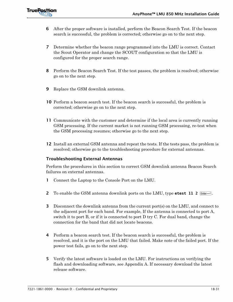
AnyPhone™ LMU 850 MHz Installation Guide
7221-1861-0000 • Revision D • Confidential and Proprietary 18-31
6 After the proper software is installed, perform the Beacon Search Test. If the beacon search is successful, the problem is corrected; otherwise go on to the next step.
7 Determine whether the beacon range programmed into the LMU is correct. Contact the Scout Operator and change the SCOUT configuration so that the LMU is configured for the proper search range.
8 Perform the Beacon Search Test. If the test passes, the problem is resolved; otherwise go on to the next step.
9 Replace the GSM downlink antenna.
10 Perform a beacon search test. If the beacon search is successful, the problem is corrected; otherwise go on to the next step.
11 Communicate with the customer and determine if the local area is currently running GSM processing. If the current market is not running GSM processing, re-test when the GSM processing resumes; otherwise go to the next step.
12 Install an external GSM antenna and repeat the tests. If the tests pass, the problem is resolved; otherwise go to the troubleshooting procedure for external antennas.
Troubleshooting External Antennas
Perform the procedures in this section to correct GSM downlink antenna Beacon Search failures on external antennas.
1 Connect the Laptop to the Console Port on the LMU.
2 To enable the GSM antenna downlink ports on the LMU, type etest 11 2 R.
3 Disconnect the downlink antenna from the current port(s) on the LMU, and connect to the adjacent port for each band. For example, If the antenna is connected to port A, switch it to port B, or if it is connected to port D try C. For dual band, change the connection for the band that did not locate beacons.
4 Perform a beacon search test. If the beacon search is successful, the problem is resolved, and it is the port on the LMU that failed. Make note of the failed port. If the power test fails, go on to the next step.
5 Verify the latest software is loaded on the LMU. For instructions on verifying the flash and downloading software, see Appendix A. If necessary download the latest release software.
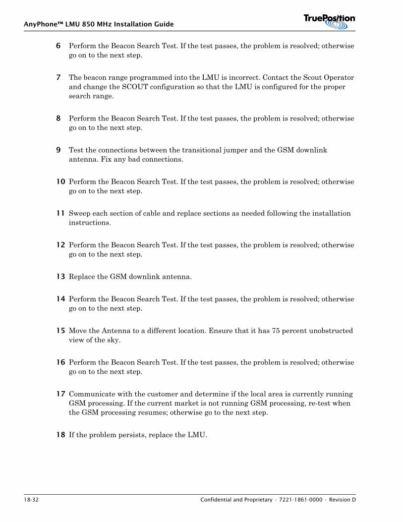
AnyPhone™ LMU 850 MHz Installation Guide
18-32 Confidential and Proprietary • 7221-1861-0000 • Revision D
6 Perform the Beacon Search Test. If the test passes, the problem is resolved; otherwise go on to the next step.
7 The beacon range programmed into the LMU is incorrect. Contact the Scout Operator and change the SCOUT configuration so that the LMU is configured for the proper search range.
8 Perform the Beacon Search Test. If the test passes, the problem is resolved; otherwise go on to the next step.
9 Test the connections between the transitional jumper and the GSM downlink antenna. Fix any bad connections.
10 Perform the Beacon Search Test. If the test passes, the problem is resolved; otherwise go on to the next step.
11 Sweep each section of cable and replace sections as needed following the installation instructions.
12 Perform the Beacon Search Test. If the test passes, the problem is resolved; otherwise go on to the next step.
13 Replace the GSM downlink antenna.
14 Perform the Beacon Search Test. If the test passes, the problem is resolved; otherwise go on to the next step.
15 Move the Antenna to a different location. Ensure that it has 75 percent unobstructed view of the sky.
16 Perform the Beacon Search Test. If the test passes, the problem is resolved; otherwise go on to the next step.
17 Communicate with the customer and determine if the local area is currently running GSM processing. If the current market is not running GSM processing, re-test when the GSM processing resumes; otherwise go to the next step.
18 If the problem persists, replace the LMU.
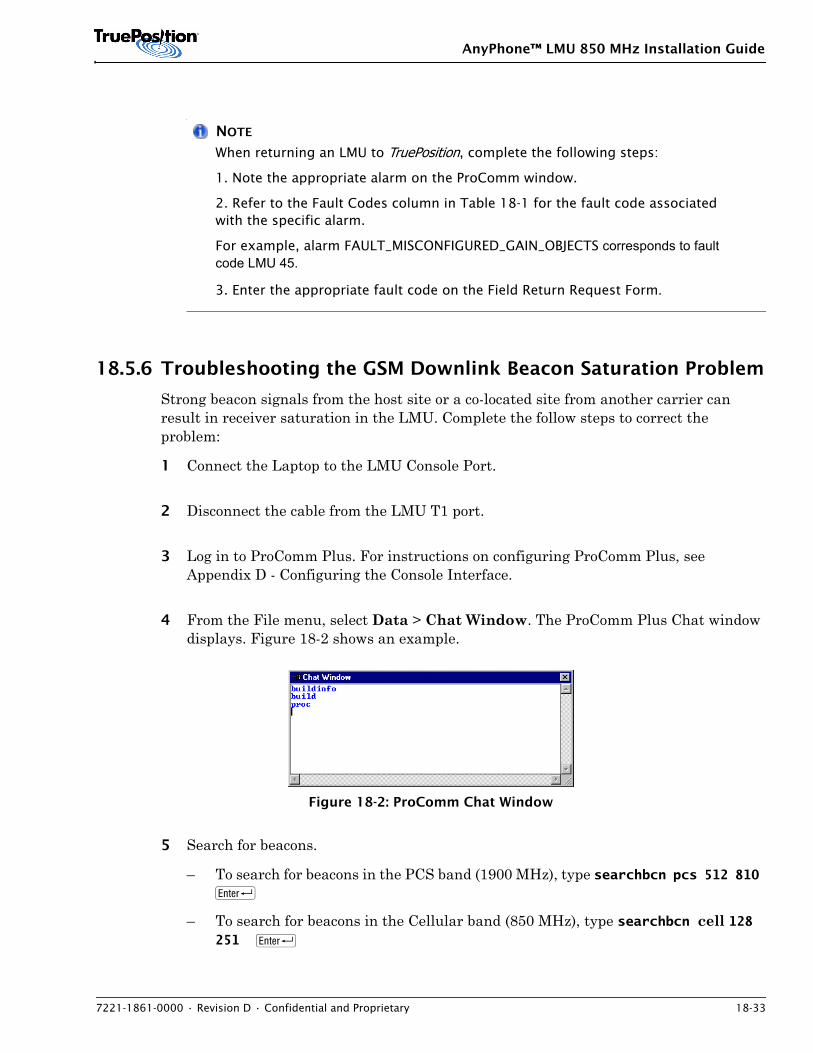
AnyPhone™ LMU 850 MHz Installation Guide
7221-1861-0000 • Revision D • Confidential and Proprietary 18-33
NOTE
When returning an LMU to TruePosition, complete the following steps:
1. Note the appropriate alarm on the ProComm window.
2. Refer to the Fault Codes column in Table 18-1 for the fault code associated with the specific alarm.
For example, alarm FAULT_MISCONFIGURED_GAIN_OBJECTS corresponds to fault code LMU 45.
3. Enter the appropriate fault code on the Field Return Request Form.
18.5.6 Troubleshooting the GSM Downlink Beacon Saturation Problem
Strong beacon signals from the host site or a co-located site from another carrier can result in receiver saturation in the LMU. Complete the follow steps to correct the problem:
1 Connect the Laptop to the LMU Console Port.
2 Disconnect the cable from the LMU T1 port.
3 Log in to ProComm Plus. For instructions on configuring ProComm Plus, see Appendix D - Configuring the Console Interface.
4 From the File menu, select Data > Chat Window. The ProComm Plus Chat window displays. Figure 18-2 shows an example.
Figure 18-2: ProComm Chat Window
5 Search for beacons.
– To search for beacons in the PCS band (1900 MHz), type searchbcn pcs 512 810 R
– To search for beacons in the Cellular band (850 MHz), type searchbcn cell 128 251 R
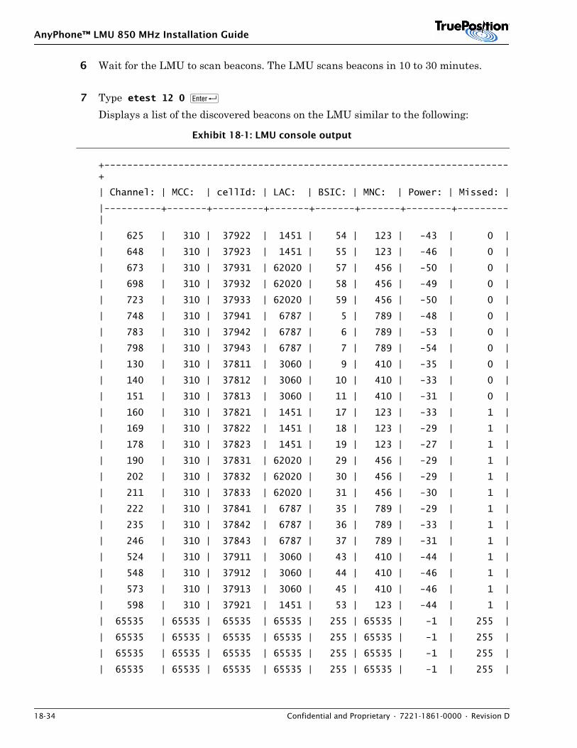
AnyPhone™ LMU 850 MHz Installation Guide
18-34 Confidential and Proprietary • 7221-1861-0000 • Revision D
6 Wait for the LMU to scan beacons. The LMU scans beacons in 10 to 30 minutes.
7 Type etest 12 0 R
Displays a list of the discovered beacons on the LMU similar to the following:
Exhibit 18-1: LMU console output
+-----------------------------------------------------------------------+
| Channel: | MCC: | cellId: | LAC: | BSIC: | MNC: | Power: | Missed: |
|----------+-------+---------+-------+-------+-------+--------+---------|
| 625 | 310 | 37922 | 1451 | 54 | 123 | -43 | 0 |
| 648 | 310 | 37923 | 1451 | 55 | 123 | -46 | 0 |
| 673 | 310 | 37931 | 62020 | 57 | 456 | -50 | 0 |
| 698 | 310 | 37932 | 62020 | 58 | 456 | -49 | 0 |
| 723 | 310 | 37933 | 62020 | 59 | 456 | -50 | 0 |
| 748 | 310 | 37941 | 6787 | 5 | 789 | -48 | 0 |
| 783 | 310 | 37942 | 6787 | 6 | 789 | -53 | 0 |
| 798 | 310 | 37943 | 6787 | 7 | 789 | -54 | 0 |
| 130 | 310 | 37811 | 3060 | 9 | 410 | -35 | 0 |
| 140 | 310 | 37812 | 3060 | 10 | 410 | -33 | 0 |
| 151 | 310 | 37813 | 3060 | 11 | 410 | -31 | 0 |
| 160 | 310 | 37821 | 1451 | 17 | 123 | -33 | 1 |
| 169 | 310 | 37822 | 1451 | 18 | 123 | -29 | 1 |
| 178 | 310 | 37823 | 1451 | 19 | 123 | -27 | 1 |
| 190 | 310 | 37831 | 62020 | 29 | 456 | -29 | 1 |
| 202 | 310 | 37832 | 62020 | 30 | 456 | -29 | 1 |
| 211 | 310 | 37833 | 62020 | 31 | 456 | -30 | 1 |
| 222 | 310 | 37841 | 6787 | 35 | 789 | -29 | 1 |
| 235 | 310 | 37842 | 6787 | 36 | 789 | -33 | 1 |
| 246 | 310 | 37843 | 6787 | 37 | 789 | -31 | 1 |
| 524 | 310 | 37911 | 3060 | 43 | 410 | -44 | 1 |
| 548 | 310 | 37912 | 3060 | 44 | 410 | -46 | 1 |
| 573 | 310 | 37913 | 3060 | 45 | 410 | -46 | 1 |
| 598 | 310 | 37921 | 1451 | 53 | 123 | -44 | 1 |
| 65535 | 65535 | 65535 | 65535 | 255 | 65535 | -1 | 255 |
| 65535 | 65535 | 65535 | 65535 | 255 | 65535 | -1 | 255 |
| 65535 | 65535 | 65535 | 65535 | 255 | 65535 | -1 | 255 |
| 65535 | 65535 | 65535 | 65535 | 255 | 65535 | -1 | 255 |

AnyPhone™ LMU 850 MHz Installation Guide
7221-1861-0000 • Revision D • Confidential and Proprietary 18-35
| 65535 | 65535 | 65535 | 65535 | 255 | 65535 | -1 | 255 |
| 65535 | 65535 | 65535 | 65535 | 255 | 65535 | -1 | 255 |
| 65535 | 65535 | 65535 | 65535 | 255 | 65535 | -1 | 255 |
| 65535 | 65535 | 65535 | 65535 | 255 | 65535 | -1 | 255 |
| 65535 | 65535 | 65535 | 65535 | 255 | 65535 | -1 | 255 |
| 65535 | 65535 | 65535 | 65535 | 255 | 65535 | -1 | 255 |
| 65535 | 65535 | 65535 | 65535 | 255 | 65535 | -1 | 255 |
| 65535 | 65535 | 65535 | 65535 | 255 | 65535 | -1 | 255 |
| 65535 | 65535 | 65535 | 65535 | 255 | 65535 | -1 | 255 |
| 65535 | 65535 | 65535 | 65535 | 255 | 65535 | -1 | 255
| 65535 | 65535 | 65535 | 65535 | 255 | 65535 | -1 | 255 |
| 65535 | 65535 | 65535 | 65535 | 255 | 65535 | -1 | 255 |
+----------------------------------------------------------------------+
NOTE
Ignore entries with channel 65535.
8 Determine if there are duplicate beacons or a beacon with a power level of -10dB or greater.
– Duplicate beacons occur when more than one beacon contains the same cell global identity. Beacons have the same cell global identity when the MCC, MNC, CellId, and LAC values are the same for different beacons. For an example of MCC, MNC, CellId, and LAC values, see Exibit 18-1.
– Beacons have a power level greater than -10 dB, when the power level for a beacon shows a value greater than -10 dB. For example, -5 or 15 dB. Exibit 18-1 shows a list of power levels for beacons located by an LMU.
If either of these conditions exist go to step 9. Otherwise, the procedure is complete and the LMU is not experiencing beacon saturation problems.
9 Type ?DWNLNKGAIN <Band> R
where <Band> is 0 for Cellular or 1 for PCS.The current configured downlink gain displays in message similar to the following:CONFIGURED DOWNLINK PCS GAIN: 43 -- or -- CONFIGURED DOWNLINK CELLULAR GAIN: 25
10 Type DWNLNKGAIN <BAND> <GAIN> R
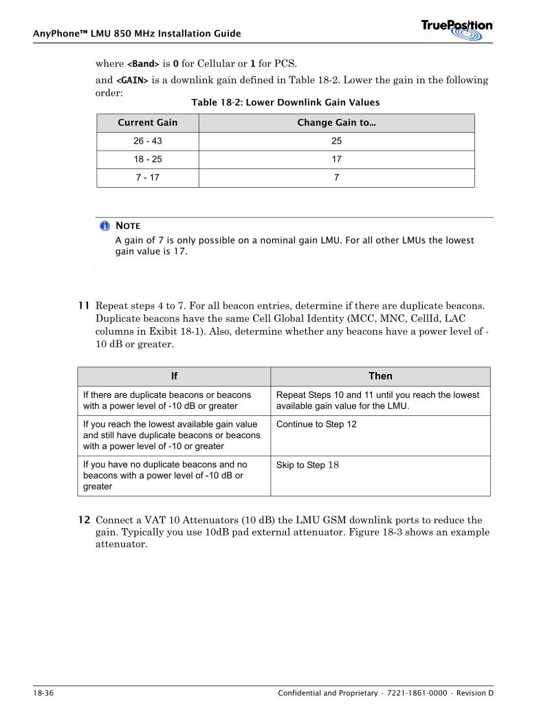
AnyPhone™ LMU 850 MHz Installation Guide
18-36 Confidential and Proprietary • 7221-1861-0000 • Revision D
where <Band> is 0 for Cellular or 1 for PCS.and <GAIN> is a downlink gain defined in Table 18-2. Lower the gain in the following order:
NOTE
A gain of 7 is only possible on a nominal gain LMU. For all other LMUs the lowest gain value is 17.
11 Repeat steps 4 to 7. For all beacon entries, determine if there are duplicate beacons. Duplicate beacons have the same Cell Global Identity (MCC, MNC, CellId, LAC columns in Exibit 18-1). Also, determine whether any beacons have a power level of -10 dB or greater.
12 Connect a VAT 10 Attenuators (10 dB) the LMU GSM downlink ports to reduce the gain. Typically you use 10dB pad external attenuator. Figure 18-3 shows an example attenuator.
Table 18-2: Lower Downlink Gain Values
Current Gain Change Gain to...
26 - 43 25
18 - 25 17
7 - 17 7
If Then
If there are duplicate beacons or beacons with a power level of -10 dB or greater
Repeat Steps 10 and 11 until you reach the lowest available gain value for the LMU.
If you reach the lowest available gain value and still have duplicate beacons or beacons with a power level of -10 or greater
Continue to Step 12
If you have no duplicate beacons and no beacons with a power level of -10 dB or greater
Skip to Step 18
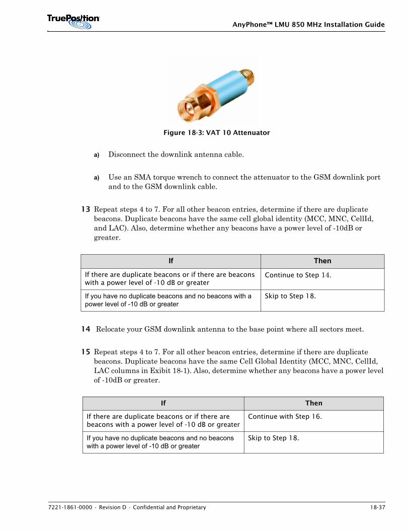
AnyPhone™ LMU 850 MHz Installation Guide
7221-1861-0000 • Revision D • Confidential and Proprietary 18-37
Figure 18-3: VAT 10 Attenuator
a) Disconnect the downlink antenna cable.
a) Use an SMA torque wrench to connect the attenuator to the GSM downlink port and to the GSM downlink cable.
13 Repeat steps 4 to 7. For all other beacon entries, determine if there are duplicate beacons. Duplicate beacons have the same cell global identity (MCC, MNC, CellId, and LAC). Also, determine whether any beacons have a power level of -10dB or greater.
14 Relocate your GSM downlink antenna to the base point where all sectors meet.
15 Repeat steps 4 to 7. For all other beacon entries, determine if there are duplicate beacons. Duplicate beacons have the same Cell Global Identity (MCC, MNC, CellId, LAC columns in Exibit 18-1). Also, determine whether any beacons have a power level of -10dB or greater.
If Then
If there are duplicate beacons or if there are beacons with a power level of -10 dB or greater
Continue to Step 14.
If you have no duplicate beacons and no beacons with a power level of -10 dB or greater
Skip to Step 18.
If Then
If there are duplicate beacons or if there are beacons with a power level of -10 dB or greater
Continue with Step 16.
If you have no duplicate beacons and no beacons with a power level of -10 dB or greater
Skip to Step 18.
AnyPhone™ LMU 850 MHz Installation Guide
18-38 Confidential and Proprietary • 7221-1861-0000 • Revision D
16 If the problem persists (the saturation is caused by another carrier's co-located cell site), connect a VAT 20 Attenuators (20 dB) the LMU GSM downlink ports to reduce the gain.
a) Disconnect the downlink antenna cable.
a) Use an SMA torque wrench to connect the Attenuator to the GSM downlink port and to the GSM downlink cable.
17 Repeat steps 4 to 7 to re-validate the beacon entries. If you are still experiencing a saturation problem, contact the TAC.
18 Once you have determined the correct gain values, communicate the new gain setting to the MTSO technician or the SCOUT operator to implement the new settings in SCOUT. The SCOUT configuration must be changed and the changes exported to the OSSGateway. For instructions on updating the SCOUT Configuration, see the WLS Finder Online Help.
18.5.7 Correcting E1 and T1 Problems
1 Call the MTSO and see if the SMLC is online.
2 If the SMLC is online, use the T-Berd 2200 to test the E1 or T1 cable.
3 If the E1 or T1 cable is good, verify that the LMU has been configured per instructions.
4 If the LMU is configured properly, verify the E1 or T1 framing and coding at the carrier-provided drop-and-insert equipment.
5 If the E1 or T1 framing and coding does not match the LMU configuration, change the LMU configuration to match the correct E1 or T1 configuration.
6 If the LMU framing and coding is correct, perform E1 or T1 local loopback test. For instructions, see Section 18.5.8: Local Loopback Test.
7 If the LMU passes the local loopback test, contact the EMS operator and perform a remote loopback test with the MTSO.
8 If the remote loopback test does not identify a problem, install a new LMU.
AnyPhone™ LMU 850 MHz Installation Guide
7221-1861-0000 • Revision D • Confidential and Proprietary 18-39
NOTE
When returning an LMU to TruePosition, complete the following steps:
1. Note the appropriate alarm on the ProComm window.
2. Refer to the Fault Codes column in Table 18-1 for the fault code associated with the specific alarm.
For example, alarm FAULT_MISCONFIGURED_GAIN_OBJECTS corresponds to fault code LMU 45.
3. Enter the appropriate fault code on the Field Return Request Form.
9 If replacing the LMU does not correct the problem, re-install the LMU you un-installed in step 8.
10 If performing the remote loopback test and replacing the LMU did not resolve the problem, have the MTSO test the E1 or T1 line.
18.5.8 Local Loopback Test
The local loopback test is used to troubleshoot E1 or T1 communication failures. This test determines if the T1/E1 port on the LMU front panel is functioning properly. To perform the test, you must set the LMU strapping for E1 regardless of whether you are performing T1 or E1 testing.
Perform loopback test using a loopback connector assembly and the LMU console port commands.
Prepare for Loopback Test
This test requires the use of a loopback connector assembly AD-06-1131-00. The T1 loopback connector assembly is an RJ-45 connector that plugs into the LMU E1 / T1 port.
Perform Loopback Test
To perform the local loopback test:
1 Set the strapping to E1. For instructions, see 13: Set Up Strapping. If the LMU is already configured for E1, skip this step.
AnyPhone™ LMU 850 MHz Installation Guide
18-40 Confidential and Proprietary • 7221-1861-0000 • Revision D
NOTE
E1 is only available on LMUs with the necessary hardware. To determine whether you are installing an LMU that is enabled for E1 processing, perform the SETNETWORKTYPE command. If E1 is available, the setting appears in a list (E1, T1 and V.35). For detailed instructions, see Appendix D - Console Port User Guide.
2 In the ProComm chat window, type gomaster and then press R.
3 Connect the T1 loopback connector assembly to the LMU T1 port.
4 Type runlocalloop 50 10 and then press R. Passing tests occur when:
– Good responses are equal to the number of reports requested.
– Bad responses are equal to zero.Failing tests occur when:
– Good responses are not equal to the number of reports requested.
– Bad responses are greater than zero.A passing test from the runlocalt1 50 10 command is shown in the example below:Good 10, Bad 0Good 10, Bad 0Good 10, Bad 0Good 10, Bad 0Good 10, Bad 0Replace units that provide failing test results. Refer to 18.6: Remove and Replace Procedures.
NOTE
When returning an LMU to TruePosition, complete the following steps:
1. Note the appropriate alarm on the ProComm window.
2. Refer to the Fault Codes column in Table 18-1 for the fault code associated with the specific alarm.
For example, alarm FAULT_MISCONFIGURED_GAIN_OBJECTS corresponds to fault code LMU 45.
3. Enter the appropriate fault code on the Field Return Request Form.
AnyPhone™ LMU 850 MHz Installation Guide
7221-1861-0000 • Revision D • Confidential and Proprietary 18-41
5 Remove the loopback connector assembly from the LMU T1 port.
6 If you changed the LMU strapping from T1 to E1 for the test, return the strapping to T1.
18.5.9 Correcting Strapping
If the LMU is having a problem communicating with the SMLC, there may be an error in the strapping information associated with the LMU. For instructions on setting strapping on an LMU, refer to 13: Set Up Strapping.
NOTE
Inform the SCOUT operator of any changes you made.
18.5.10 Test for Power
When the status LED fails to illuminate during the LMU power up sequence perform the following:
1 If the DC Power Terminal Block is contacting debris or equipment that may be causing an electrical short, correct the problem by removing or relocating the material.
2 If necessary, disconnect and reconnect the power cables. at the LMU DC block.
NOTE
For information on connecting and disconnecting power, refer to 9: Power Connections.
3 Listen for fans.
4 Press the LMU Reset button.
5 If the LED does not illuminate after 30 seconds go to step 6.
6 Turn off the LMU supply-line-cable power source at the breaker or fuse.
AnyPhone™ LMU 850 MHz Installation Guide
18-42 Confidential and Proprietary • 7221-1861-0000 • Revision D
7 Visually inspect the pigtail and supply-line connection. Replace the pigtail connection if it is damaged. Contact the carrier for assistance if the supply-line cable is damaged.
8 If the cable passes visual inspection, reconnect the supply-line-cable to the LMU pigtail cable.
9 Restore power to the supply-line-cable.
10 Remove the LMU pigtail cable from the supply-line-cable.
11 Restore power to the supply-line-cable.
12 Measure the voltage level of the supply-line-cable for 22 to 24 VDC or –44 to –54 VDC.
13 Turn off supply-line-cable power source.
14 If the voltage measurements are within limits re-connect the LMU pigtail cable and go to step 4.
15 If the voltage measurements are not within limits contact the carrier for assistance.
Replace units that provide failing test results. Refer to 18.6: Remove and Replace Procedures.
NOTE
When returning an LMU to TruePosition, complete the following steps:
1. Note the appropriate alarm on the ProComm window.
2. Refer to the Fault Codes column in Table 18-1 for the fault code associated with the specific alarm.
For example, alarm FAULT_MISCONFIGURED_GAIN_OBJECTS corresponds to fault code LMU 45.
3. Enter the appropriate fault code on the Field Return Request Form.
18.5.11GPS Self-survey Test
When the LMU receives a GPS Position Changed error, you must perform a GPS Self-survey test to determine position recorded by the LMU for the GPS antenna. Refer to GPS Self-Survey Operations Manual 7221-1989-0000.
AnyPhone™ LMU 850 MHz Installation Guide
7221-1861-0000 • Revision D • Confidential and Proprietary 18-43
NOTE
The LMU cannot perform location processing while the test is being run.
1 At the LMU> prompt type BIT 9 0 0 and press R. The LMU displays the current GPS antenna latitude and longitude.
2 If the latitude, longitude and altitude reported by the LMU match the values recorded in the SCOUT application, no further action is required.
3 If the latitude and longitude reported by the LMU do not match the values recorded in the SCOUT application, enter the correct values by following the instructions in Section 14: Set GPS Parameters.The LMU resets with the correct latitude and longitude. How long it takes for the LMU to establish the correct GPS antenna location depends on how large a correction it must make.
18.5.12AOA Troubleshooting Procedures
If the LMU connects to Ground Based Equipment, alarms for AOA related problems display on the ProComm Plus Alarm window on the LMU. For information about troubleshooting AOA alarms, see the Angle of Arrival System Installation Guide, Troubleshooting section.
18.5.13BTS Synchronization Troubleshooting
To determine whether the LMU is providing a synchronization signal to the BTS, connect the laptop to the ENV/AOA port on the front panel of the LMU using the same cable (AD-06-1113-00) that you use when connecting to the Console port.
BTS synchronization messages appear on the lap top similar to the following:$PXXX,GPppr,328044,01307,00050,10,0,0*49
$PXXX,GPppr,328045,01307,00050,10,0,0*48
$PXXX,GPppr,328046,01307,00050,10,0,0*4b
$PXXX,GPppr,328047,01307,00050,10,0,0*4a
If no messages appear, perform the following actions:
1 Verify that the LMU is using the appropriate software version for performing BTS synchronization. The LMU must have software for release 9.1 or higher.
2 Contact the SCOUT operator, and confirm that the LMU is configured for BTS synchronization.
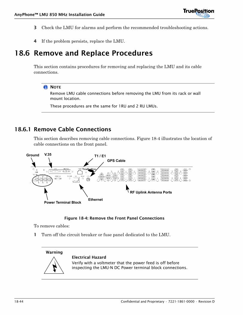
AnyPhone™ LMU 850 MHz Installation Guide
18-44 Confidential and Proprietary • 7221-1861-0000 • Revision D
3 Check the LMU for alarms and perform the recommended troubleshooting actions.
4 If the problem persists, replace the LMU.
18.6 Remove and Replace Procedures
This section contains procedures for removing and replacing the LMU and its cable connections.
NOTE
Remove LMU cable connections before removing the LMU from its rack or wall mount location.
These procedures are the same for 1RU and 2 RU LMUs.
18.6.1 Remove Cable Connections
This section describes removing cable connections. Figure 18-4 illustrates the location of cable connections on the front panel.
Figure 18-4: Remove the Front Panel Connections
To remove cables:
1 Turn off the circuit breaker or fuse panel dedicated to the LMU.
WarningElectrical HazardVerify with a voltmeter that the power feed is off before inspecting the LMU-N DC Power terminal block connections.
Power Terminal Block
Ground V.35 T1 / E1
Ethernet
GPS Cable
RF Uplink Antenna Ports
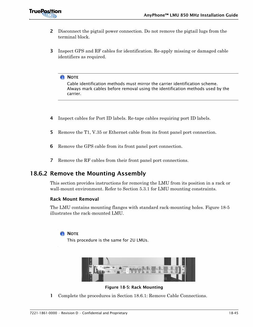
AnyPhone™ LMU 850 MHz Installation Guide
7221-1861-0000 • Revision D • Confidential and Proprietary 18-45
2 Disconnect the pigtail power connection. Do not remove the pigtail lugs from the terminal block.
3 Inspect GPS and RF cables for identification. Re-apply missing or damaged cable identifiers as required.
NOTE
Cable identification methods must mirror the carrier identification scheme. Always mark cables before removal using the identification methods used by the carrier.
4 Inspect cables for Port ID labels. Re-tape cables requiring port ID labels.
5 Remove the T1, V.35 or Ethernet cable from its front panel port connection.
6 Remove the GPS cable from its front panel port connection.
7 Remove the RF cables from their front panel port connections.
18.6.2 Remove the Mounting Assembly
This section provides instructions for removing the LMU from its position in a rack or wall-mount environment. Refer to Section 5.3.1 for LMU mounting constraints.
Rack Mount Removal
The LMU contains mounting flanges with standard rack-mounting holes. Figure 18-5 illustrates the rack-mounted LMU.
NOTE
This procedure is the same for 2U LMUs.
Figure 18-5: Rack Mounting
1 Complete the procedures in Section 18.6.1: Remove Cable Connections.
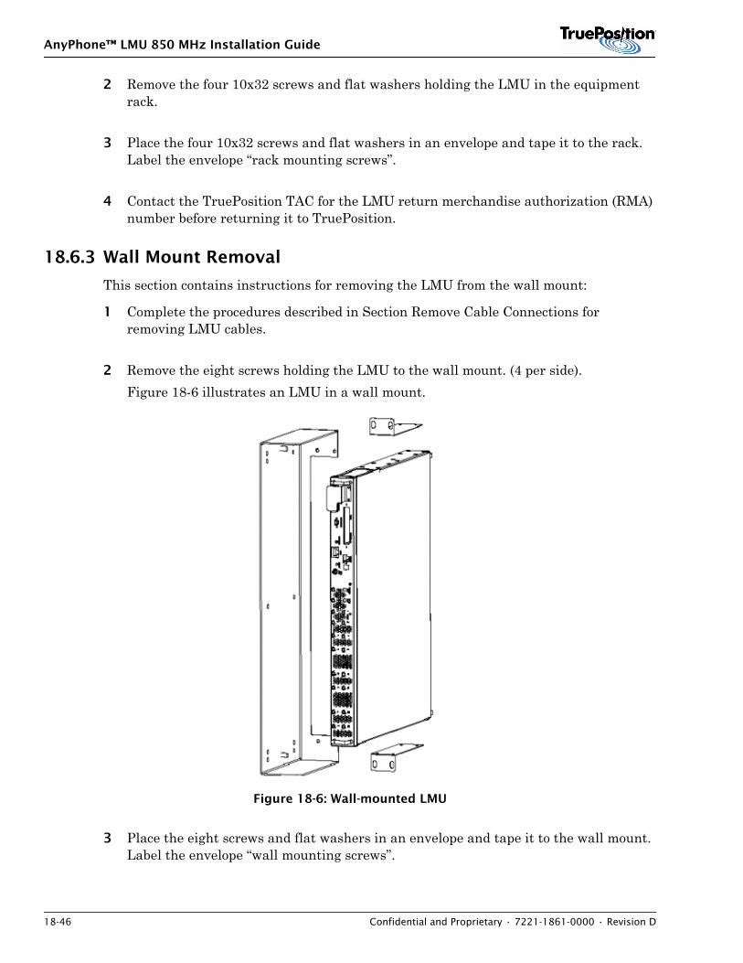
AnyPhone™ LMU 850 MHz Installation Guide
18-46 Confidential and Proprietary • 7221-1861-0000 • Revision D
2 Remove the four 10x32 screws and flat washers holding the LMU in the equipment rack.
3 Place the four 10x32 screws and flat washers in an envelope and tape it to the rack. Label the envelope “rack mounting screws”.
4 Contact the TruePosition TAC for the LMU return merchandise authorization (RMA) number before returning it to TruePosition.
18.6.3 Wall Mount Removal
This section contains instructions for removing the LMU from the wall mount:
1 Complete the procedures described in Section Remove Cable Connections for removing LMU cables.
2 Remove the eight screws holding the LMU to the wall mount. (4 per side). Figure 18-6 illustrates an LMU in a wall mount.
Figure 18-6: Wall-mounted LMU
3 Place the eight screws and flat washers in an envelope and tape it to the wall mount. Label the envelope “wall mounting screws”.
AnyPhone™ LMU 850 MHz Installation Guide
7221-1861-0000 • Revision D • Confidential and Proprietary 18-47
4 Contact the TruePosition TAC for the LMU return merchandise authorization (RMA) number before returning it to TruePosition.
18.6.4 Replace the LMU in its Mounting Assembly
For instructions on replacing the LMU in a rack or wall mount location, refer to Section 8.
18.6.5 Replace Cable Connections
Refer to Section 8 Chassis Mounting and Installation for replacing:
• Ground and power cables
• RF Cables
• Transitional jumper cables
• V.35 cable
• T1 cable

AnyPhone™ LMU 850 MHz Installation Guide
18-48 Confidential and Proprietary • 7221-1861-0000 • Revision D
AnyPhone™ LMU 850 MHz Installation Guide
7221-1861-0000 • Revision D • Confidential and Proprietary A-1
APPENDIX A. CONSOLE PORT USER GUIDE
ContentsA.1 Overview . . . . . . . . . . . . . . . . . . . . . . . . . . . . . . . A-1A.2 Configuring the Console Interface . . . . . . . . . . . . . . . . . . . . . . . . . . . . . . . . . . . . . . . . . . A-1A.3 Downloading Software Via Console Port . . . . . . . . . . . . . . . . . . . . . . . . . . . . . . . . . . . . . . A-3A.4 Running the Local Loopback Test . . . . . . . . . . . . . . . . . . . . . . . . . . . . . . . . . . . . . . . . . A-14A.5 Proceed to Application Mode (No Network Connection) . . . . . . . . . . . . . . . . . . . . . . . . . A-15A.6 Displaying the GPS Antenna Status . . . . . . . . . . . . . . . . . . . . . . . . . . . . . . . . . . . . . . . . A-15A.7 Standard Commands . . . . . . . . . . . . . . . . . . . . . . . . . . . . . . . . . . . . . . . . . . . . . . . . . . . A-15A.8 AOA Commands . . . . . . . . . . . . . . . . . . . . . . . . . . . . . . . . . . . . . . . . . . . . . . . . . . . . . . A-25A.9 Engineering Commands . . . . . . . . . . . . . . . . . . . . . . . . . . . . . . . . . . . . . . . . . . . . . . . . . A-27
A.1 OverviewThe Console Port User Guide defines commands available on the LMU. These commands allow you to configure, test, and troubleshoot the LMU. Communicate with the LMU using a laptop connected to the LMU’s Console Port. The laptop acts as data terminal equipment.
After power-up or reset, the console port provides an interface to the standard operating mode, which displays an LMU> prompt.
For additional information about ProComm Plus®, see the ProComm Plus online help.
A.2 Configuring the Console InterfaceThe LMU front panel contains a DB-9 RS232 port. Connect to this port using Cable Assembly DB9 Interface 72.00 inch adapter, part number AD-06-1113-00. Connect other end to RS232 on the laptop. Configure ProComm Plus as shown in Table A-1.
Table A-1: ProComm Plus settings
Parameter Setting Notes
Baud 115.2 k
Handshake N-8-1 No parity, 8 bits, 1 stop bit.
Protocol Raw ASCII
Terminal VT-100
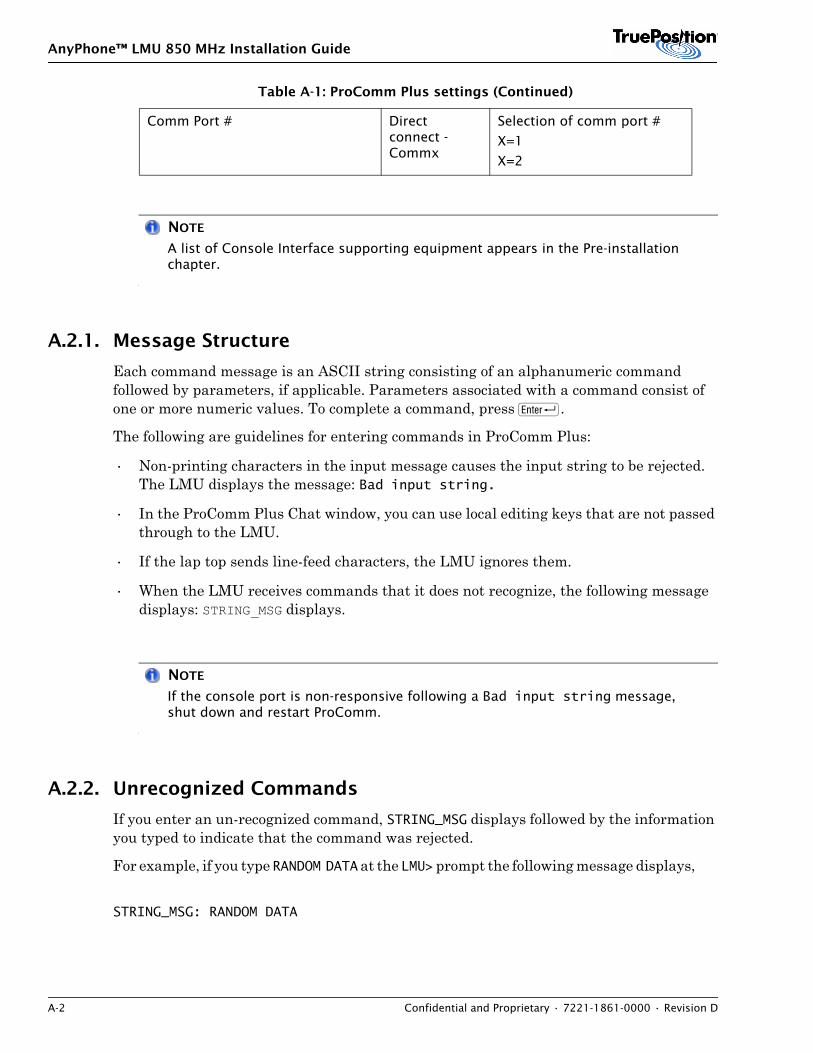
AnyPhone™ LMU 850 MHz Installation Guide
A-2 Confidential and Proprietary • 7221-1861-0000 • Revision D
NOTE
A list of Console Interface supporting equipment appears in the Pre-installation chapter.
A.2.1. Message Structure
Each command message is an ASCII string consisting of an alphanumeric command followed by parameters, if applicable. Parameters associated with a command consist of one or more numeric values. To complete a command, press R.
The following are guidelines for entering commands in ProComm Plus:
• Non-printing characters in the input message causes the input string to be rejected. The LMU displays the message: Bad input string.
• In the ProComm Plus Chat window, you can use local editing keys that are not passed through to the LMU.
• If the lap top sends line-feed characters, the LMU ignores them.
• When the LMU receives commands that it does not recognize, the following message displays: STRING_MSG displays.
NOTE
If the console port is non-responsive following a Bad input string message, shut down and restart ProComm.
A.2.2. Unrecognized Commands
If you enter an un-recognized command, STRING_MSG displays followed by the information you typed to indicate that the command was rejected.
For example, if you type RANDOM DATA at the LMU> prompt the following message displays,
STRING_MSG: RANDOM DATA
Comm Port # Direct connect - Commx
Selection of comm port #
X=1
X=2
Table A-1: ProComm Plus settings (Continued)
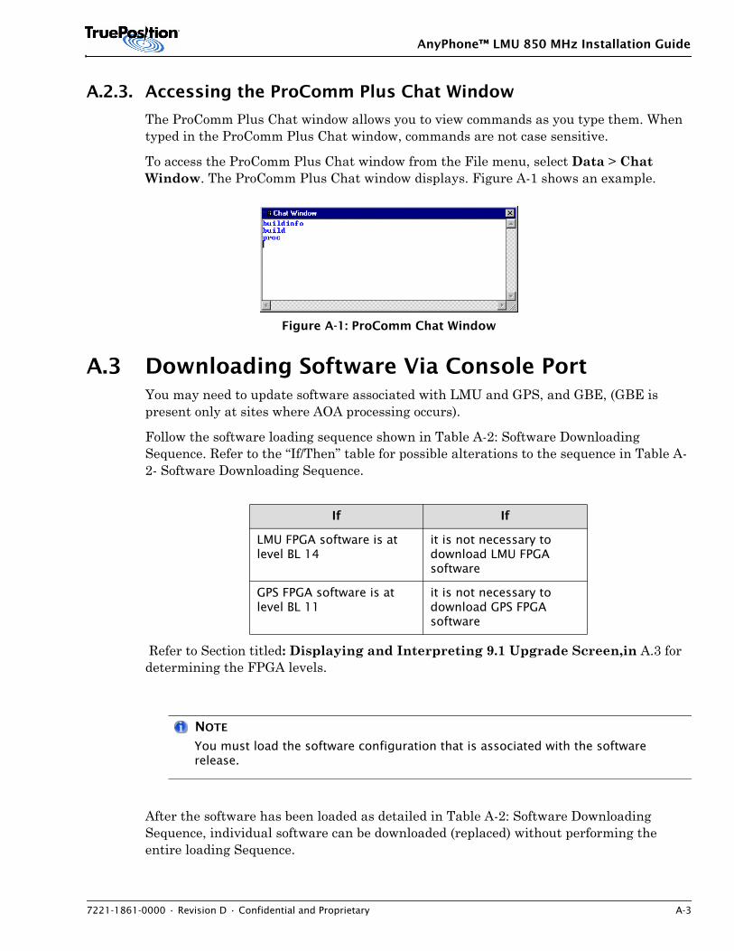
AnyPhone™ LMU 850 MHz Installation Guide
7221-1861-0000 • Revision D • Confidential and Proprietary A-3
A.2.3. Accessing the ProComm Plus Chat Window
The ProComm Plus Chat window allows you to view commands as you type them. When typed in the ProComm Plus Chat window, commands are not case sensitive.
To access the ProComm Plus Chat window from the File menu, select Data > Chat Window. The ProComm Plus Chat window displays. Figure A-1 shows an example.
Figure A-1: ProComm Chat Window
A.3 Downloading Software Via Console PortYou may need to update software associated with LMU and GPS, and GBE, (GBE is present only at sites where AOA processing occurs).
Follow the software loading sequence shown in Table A-2: Software Downloading Sequence. Refer to the “If/Then” table for possible alterations to the sequence in Table A-2- Software Downloading Sequence.
Refer to Section titled: Displaying and Interpreting 9.1 Upgrade Screen,in A.3 for determining the FPGA levels.
NOTE
You must load the software configuration that is associated with the software release.
After the software has been loaded as detailed in Table A-2: Software Downloading Sequence, individual software can be downloaded (replaced) without performing the entire loading Sequence.
If If
LMU FPGA software is at level BL 14
it is not necessary to download LMU FPGA software
GPS FPGA software is at level BL 11
it is not necessary to download GPS FPGA software
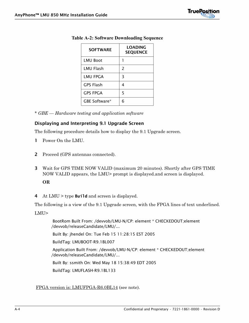
AnyPhone™ LMU 850 MHz Installation Guide
A-4 Confidential and Proprietary • 7221-1861-0000 • Revision D
* GBE — Hardware testing and application software
Displaying and Interpreting 9.1 Upgrade Screen
The following procedure details how to display the 9.1 Upgrade screen.
1 Power On the LMU.
2 Proceed (GPS antennas connected).
3 Wait for GPS TIME NOW VALID (maximum 20 minutes). Shortly after GPS TIME NOW VALID appears, the LMU> prompt is displayed.and screen is displayed.
OR
4 At LMU > type Build and screen is displayed.
The following is a view of the 9.1 Upgrade screen, with the FPGA lines of text underlined.
LMU> BootRom Built From: /devvob/LMU-N/CP: element * CHECKEDOUT;element /devvob/releaseCandidate/LMU/...
Built By: jhendel On: Tue Feb 15 11:28:15 EST 2005
BuildTag: LMUBOOT-R9.1BL007
Application Built From: /devvob/LMU-N/CP: element * CHECKEDOUT;element /devvob/releaseCandidate/LMU/...
Built By: ssmith On: Wed May 18 15:38:49 EDT 2005
BuildTag: LMUFLASH-R9.1BL133
FPGA version is: LMUFPGA-R6.0BL14 (see note).
Table A-2: Software Downloading Sequence
SOFTWARELOADING
SEQUENCE
LMU Boot 1
LMU Flash 2
LMU FPGA 3
GPS Flash 4
GPS FPGA 5
GBE Software* 6
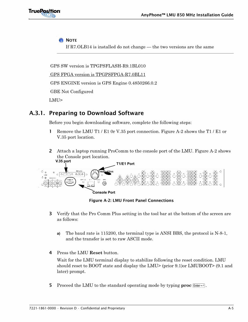
AnyPhone™ LMU 850 MHz Installation Guide
7221-1861-0000 • Revision D • Confidential and Proprietary A-5
NOTE
If R7.OLB14 is installed do not change — the two versions are the same
GPS SW version is TPGPSFLASH-R9.1BL010
GPS FPGA version is TPGPSFPGA-R7.0BL11
GPS ENGINE version is GPS Engine 0.4850266.0.2
GBE Not Configured
LMU>
A.3.1. Preparing to Download Software
Before you begin downloading software, complete the following steps:
1 Remove the LMU T1 / E1 0r V.35 port connection. Figure A-2 shows the T1 / E1 or V.35 port location.
2 Attach a laptop running ProComm to the console port of the LMU. Figure A-2 shows the Console port location.
Figure A-2: LMU Front Panel Connections
3 Verify that the Pro Comm Plus setting in the tool bar at the bottom of the screen are as follows:
a) The baud rate is 115200, the terminal type is ANSI BBS, the protocol is N-8-1, and the transfer is set to raw ASCII mode.
4 Press the LMU Reset button. Wait for the LMU terminal display to stabilize following the reset condition. LMU should reset to BOOT state and display the LMU> (prior 9.1)or LMUBOOT> (9.1 and later) prompt.
5 Proceed the LMU to the standard operating mode by typing proc R.
Console Port
T1/E1 PortV.35 port
AnyPhone™ LMU 850 MHz Installation Guide
A-6 Confidential and Proprietary • 7221-1861-0000 • Revision D
6 Wait for the Proceed command to complete. Look for messages similar to the ones below and look for LMU prompt at completion.
NOTE
The proc command is not visible on the terminal screen when you type it. When the LMU completes proceeding, the LMU> prompt appears.
BootRom Built From: /devvob/LMU-N/CP: element * CHECKEDOUT;element /devvob/releaseCandidate/LMU/...
Built By: jhendel On: Tues FEB 15 14:09:56 EST 2005
BuildTag: LMUFBOOT-R9.1BL007
Application Built From: /devvob/LMU-N/CP: element * CHECKEDOUT;element /devvob/releaseCandidate/LMU/...
Built By: ssmith On: Wed May 18 14:09:56 EST 2005
BuildTag: LMUFLASH-R9.1BL133
FPGA version is: LMUFPGA-R6.0BL14 (SEE NOTE)
NOTE
If LMUFPGA R7.OLB14 is installed do not change — the two versions are the same
GPS SW version is TPGPSFLASH-R8.0BL010
GPS FPGA version is TPGPSFPGA-R8.0BL11
GPS ENGINE version is GPS Engine 0.4850285.0.4
GBE Not ConfiguredLMU>
A.3.2. Downloading LMU Software
This section defines how to download Flash, Boot, and FPGA applications to the LMU.
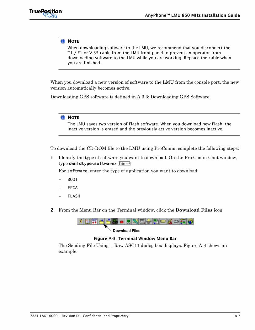
AnyPhone™ LMU 850 MHz Installation Guide
7221-1861-0000 • Revision D • Confidential and Proprietary A-7
NOTE
When downloading software to the LMU, we recommend that you disconnect the T1 / E1 or V.35 cable from the LMU front panel to prevent an operator from downloading software to the LMU while you are working. Replace the cable when you are finished.
When you download a new version of software to the LMU from the console port, the new version automatically becomes active.
Downloading GPS software is defined in A.3.3: Downloading GPS Software.
NOTE
The LMU saves two version of Flash software. When you download new Flash, the inactive version is erased and the previously active version becomes inactive.
To download the CD-ROM file to the LMU using ProComm, complete the following steps:
1 Identify the type of software you want to download. On the Pro Comm Chat window, type dwnldtype<software> R For software, enter the type of application you want to download:
– BOOT
– FPGA
– FLASH
2 From the Menu Bar on the Terminal window, click the Download Files icon.
Figure A-3: Terminal Window Menu Bar
The Sending File Using -- Raw ASC11 dialog box displays. Figure A-4 shows an example.
Download Files
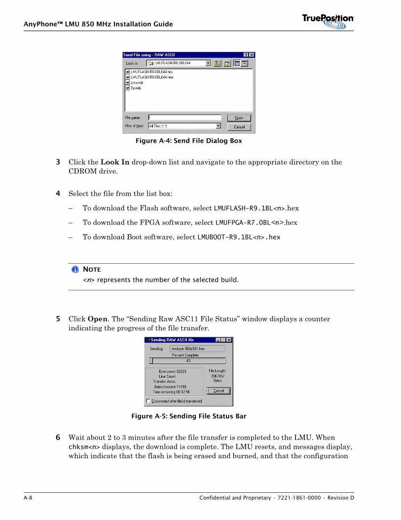
AnyPhone™ LMU 850 MHz Installation Guide
A-8 Confidential and Proprietary • 7221-1861-0000 • Revision D
Figure A-4: Send File Dialog Box
3 Click the Look In drop-down list and navigate to the appropriate directory on the CDROM drive.
4 Select the file from the list box:
– To download the Flash software, select LMUFLASH-R9.1BL<n>.hex
– To download the FPGA software, select LMUFPGA-R7.0BL<n>.hex
– To download Boot software, select LMUBOOT-R9.1BL<n>.hex
NOTE
<n> represents the number of the selected build.
5 Click Open. The “Sending Raw ASC11 File Status” window displays a counter indicating the progress of the file transfer.
Figure A-5: Sending File Status Bar
6 Wait about 2 to 3 minutes after the file transfer is completed to the LMU. When chksm<n> displays, the download is complete. The LMU resets, and messages display, which indicate that the flash is being erased and burned, and that the configuration
9
AnyPhone™ LMU 850 MHz Installation Guide
7221-1861-0000 • Revision D • Confidential and Proprietary A-9
information is being updated. Wait for the LMU terminal display to stabilize following the reset.
NOTE
When you load new boot software, the LMU resets automatically.
This command is performed with the T1 / E1 /V.35 port disconnected. The LMU behaves differently when the cable is connected.
A.3.3. Downloading GPS Software
You may be required to update the flash software for operating the GPS Receiver. Download software from the GPS receiver’s manufacturer only. Three types of GPS receivers are available:
• TPGPS
• Zyfer
• Datum
1 Verify the LMU is in the Standard Operating Mode by observing the LMU> prompt. If the LMU displays LMU> (prior 9.1)or LMUBOOT> (9.1 and later) prompt, proceed to the Standard Operating state via the Proc ENTER command wait for proceed to complete.
2 To verify the manufacturer of the GPS in the LMU, view the electronic serial numbers on the LMU. Type ?config at LMU> prompt R.
3 Identify the type of software you want to download. On the Pro Comm Chat window, type dwnldtype GPS R
WARNING The installer must be sure the LMU completed proceeding by itself and it went all the way to the LMU> prompt with no user intervention. If the LMU finished the proceeding while the GPS is being downloaded it could corrupt the GPS FLASH and render the entire LMU inoperatable.
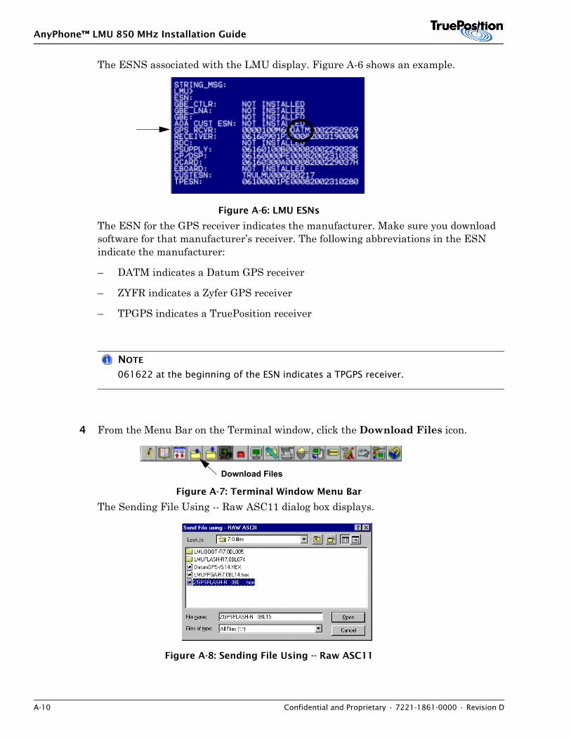
AnyPhone™ LMU 850 MHz Installation Guide
A-10 Confidential and Proprietary • 7221-1861-0000 • Revision D
The ESNS associated with the LMU display. Figure A-6 shows an example.
Figure A-6: LMU ESNs
The ESN for the GPS receiver indicates the manufacturer. Make sure you download software for that manufacturer’s receiver. The following abbreviations in the ESN indicate the manufacturer:
– DATM indicates a Datum GPS receiver
– ZYFR indicates a Zyfer GPS receiver
– TPGPS indicates a TruePosition receiver
NOTE
061622 at the beginning of the ESN indicates a TPGPS receiver.
4 From the Menu Bar on the Terminal window, click the Download Files icon.
Figure A-7: Terminal Window Menu Bar
The Sending File Using -- Raw ASC11 dialog box displays.
Figure A-8: Sending File Using -- Raw ASC11
Download Files
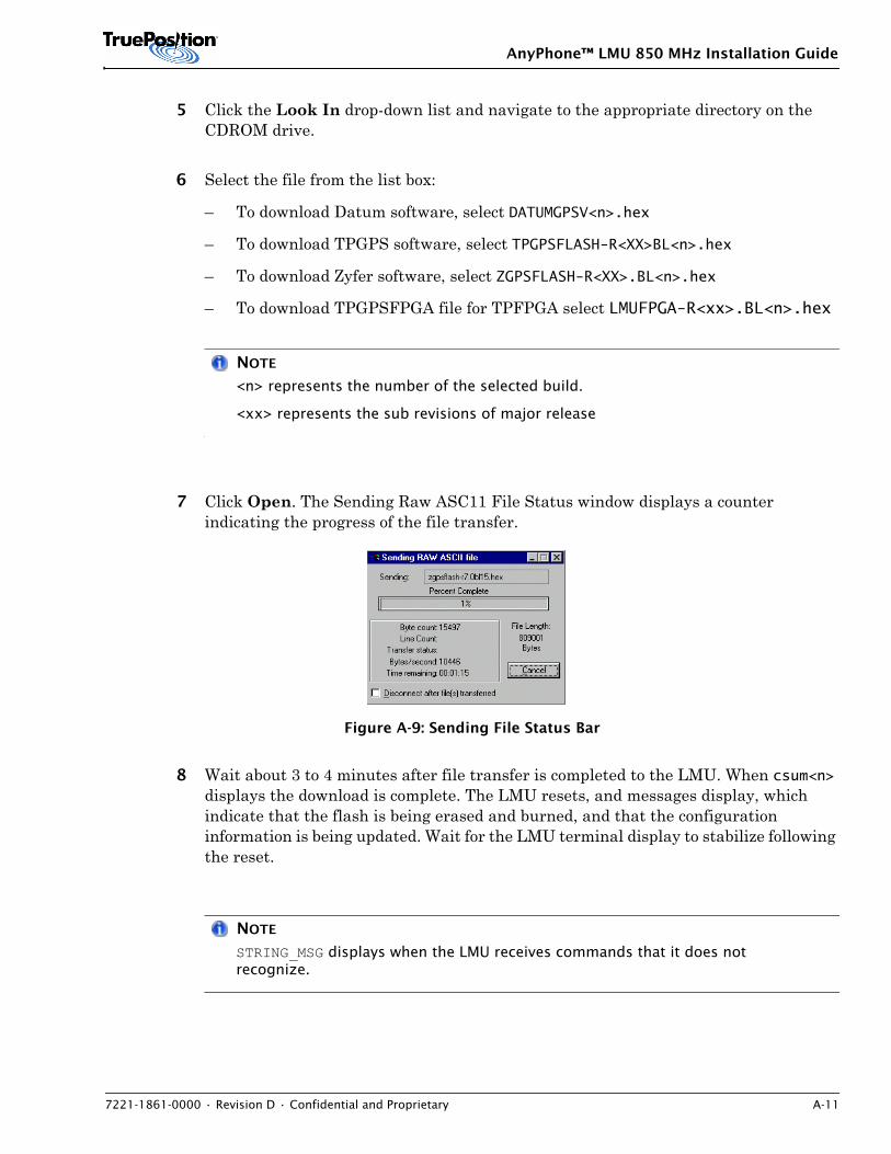
AnyPhone™ LMU 850 MHz Installation Guide
7221-1861-0000 • Revision D • Confidential and Proprietary A-11
5 Click the Look In drop-down list and navigate to the appropriate directory on the CDROM drive.
6 Select the file from the list box:
– To download Datum software, select DATUMGPSV<n>.hex
– To download TPGPS software, select TPGPSFLASH-R<XX>BL<n>.hex
– To download Zyfer software, select ZGPSFLASH-R<XX>.BL<n>.hex
– To download TPGPSFPGA file for TPFPGA select LMUFPGA-R<xx>.BL<n>.hex
NOTE
<n> represents the number of the selected build.
<xx> represents the sub revisions of major release
7 Click Open. The Sending Raw ASC11 File Status window displays a counter indicating the progress of the file transfer.
Figure A-9: Sending File Status Bar
8 Wait about 3 to 4 minutes after file transfer is completed to the LMU. When csum<n> displays the download is complete. The LMU resets, and messages display, which indicate that the flash is being erased and burned, and that the configuration information is being updated. Wait for the LMU terminal display to stabilize following the reset.
NOTE
STRING_MSG displays when the LMU receives commands that it does not recognize.
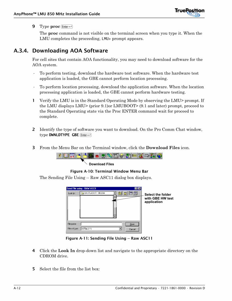
AnyPhone™ LMU 850 MHz Installation Guide
A-12 Confidential and Proprietary • 7221-1861-0000 • Revision D
9 Type proc RThe proc command is not visible on the terminal screen when you type it. When the LMU completes the proceeding, LMU> prompt appears.
A.3.4. Downloading AOA Software
For cell sites that contain AOA functionality, you may need to download software for the AOA system.
• To perform testing, download the hardware test software. When the hardware test application is loaded, the GBE cannot perform location processing.
• To perform location processing, download the application software. When the location processing application is loaded, the GBE cannot perform hardware testing.
1 Verify the LMU is in the Standard Operating Mode by observing the LMU> prompt. If the LMU displays LMU> (prior 9.1)or LMUBOOT> (9.1 and later) prompt, proceed to the Standard Operating state via the Proc ENTER command wait for proceed to complete.
2 Identify the type of software you want to download. On the Pro Comm Chat window, type DWNLDTYPE GBE R
3 From the Menu Bar on the Terminal window, click the Download Files icon.
Figure A-10: Terminal Window Menu Bar
The Sending File Using -- Raw ASC11 dialog box displays.
Figure A-11: Sending File Using -- Raw ASC11
4 Click the Look In drop-down list and navigate to the appropriate directory on the CDROM drive.
5 Select the file from the list box:
Download Files
Select the folder with GBE HW testapplication
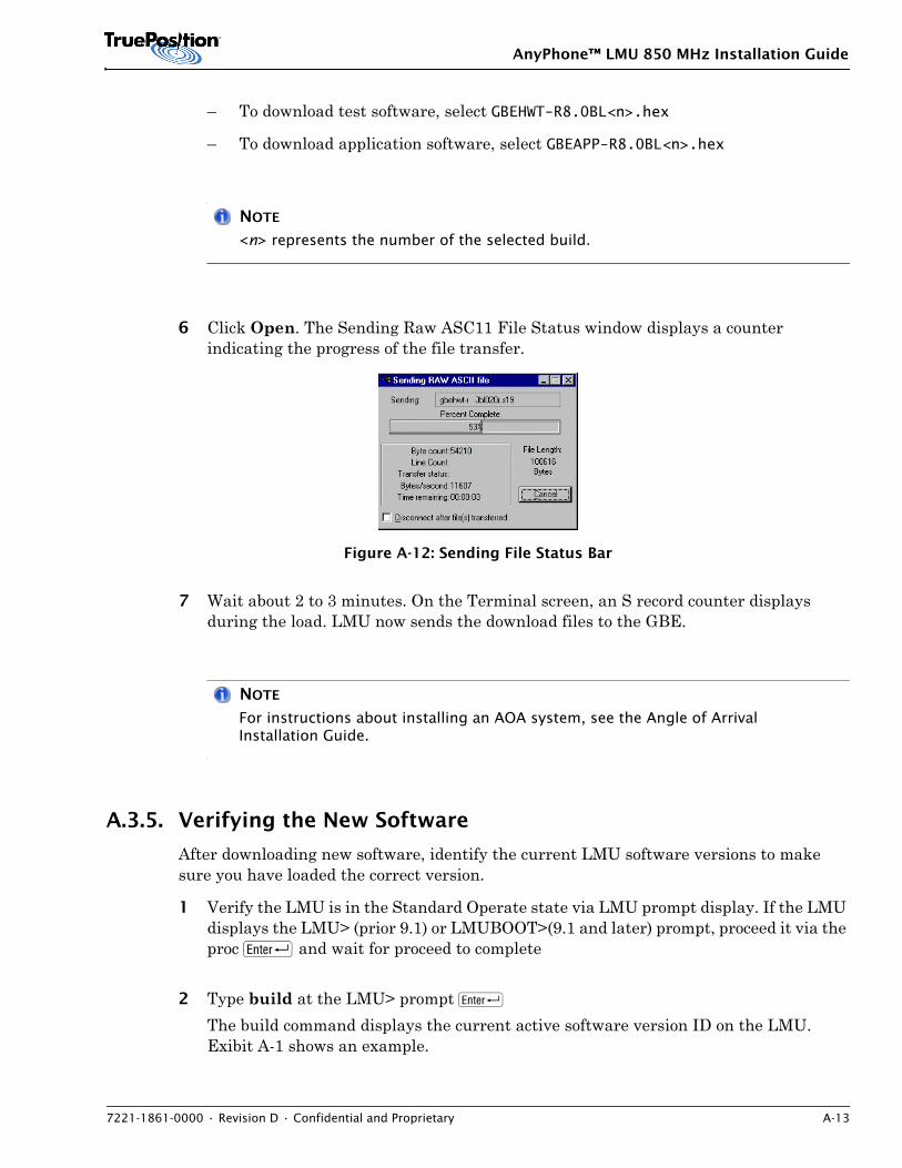
AnyPhone™ LMU 850 MHz Installation Guide
7221-1861-0000 • Revision D • Confidential and Proprietary A-13
– To download test software, select GBEHWT-R8.0BL<n>.hex
– To download application software, select GBEAPP-R8.0BL<n>.hex
NOTE
<n> represents the number of the selected build.
6 Click Open. The Sending Raw ASC11 File Status window displays a counter indicating the progress of the file transfer.
Figure A-12: Sending File Status Bar
7 Wait about 2 to 3 minutes. On the Terminal screen, an S record counter displays during the load. LMU now sends the download files to the GBE.
NOTE
For instructions about installing an AOA system, see the Angle of Arrival Installation Guide.
A.3.5. Verifying the New Software
After downloading new software, identify the current LMU software versions to make sure you have loaded the correct version.
1 Verify the LMU is in the Standard Operate state via LMU prompt display. If the LMU displays the LMU> (prior 9.1) or LMUBOOT>(9.1 and later) prompt, proceed it via the proc R and wait for proceed to complete
2 Type build at the LMU> prompt RThe build command displays the current active software version ID on the LMU. Exibit A-1 shows an example.
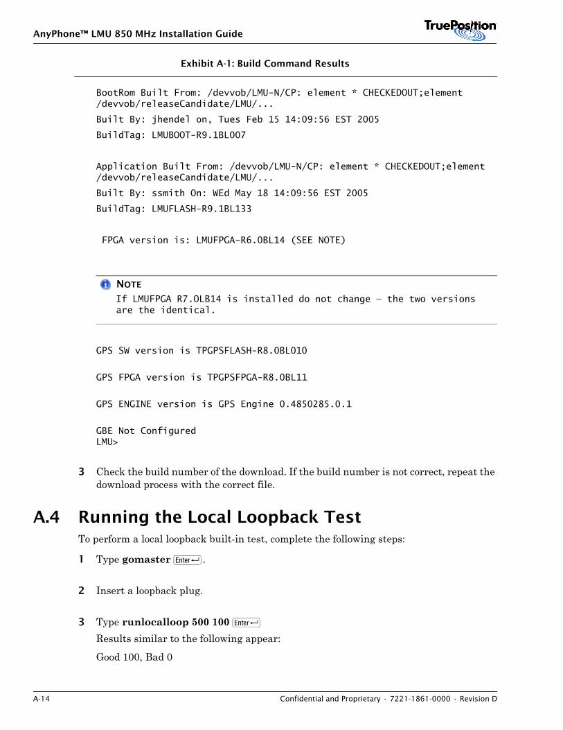
AnyPhone™ LMU 850 MHz Installation Guide
A-14 Confidential and Proprietary • 7221-1861-0000 • Revision D
Exhibit A-1: Build Command Results
BootRom Built From: /devvob/LMU-N/CP: element * CHECKEDOUT;element /devvob/releaseCandidate/LMU/...
Built By: jhendel on, Tues Feb 15 14:09:56 EST 2005
BuildTag: LMUBOOT-R9.1BL007
Application Built From: /devvob/LMU-N/CP: element * CHECKEDOUT;element /devvob/releaseCandidate/LMU/...
Built By: ssmith On: WEd May 18 14:09:56 EST 2005
BuildTag: LMUFLASH-R9.1BL133
FPGA version is: LMUFPGA-R6.0BL14 (SEE NOTE)
NOTE
If LMUFPGA R7.OLB14 is installed do not change — the two versions are the identical.
GPS SW version is TPGPSFLASH-R8.0BL010
GPS FPGA version is TPGPSFPGA-R8.0BL11
GPS ENGINE version is GPS Engine 0.4850285.0.1
GBE Not ConfiguredLMU>
3 Check the build number of the download. If the build number is not correct, repeat the download process with the correct file.
A.4 Running the Local Loopback TestTo perform a local loopback built-in test, complete the following steps:
1 Type gomaster R.
2 Insert a loopback plug.
3 Type runlocalloop 500 100 R Results similar to the following appear:
Good 100, Bad 0
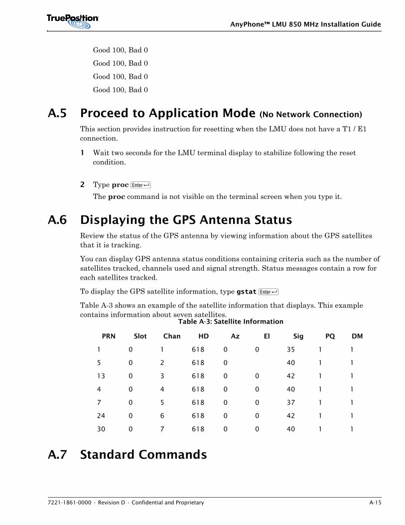
AnyPhone™ LMU 850 MHz Installation Guide
7221-1861-0000 • Revision D • Confidential and Proprietary A-15
Good 100, Bad 0
Good 100, Bad 0
Good 100, Bad 0
Good 100, Bad 0
A.5 Proceed to Application Mode (No Network Connection)
This section provides instruction for resetting when the LMU does not have a T1 / E1 connection.
1 Wait two seconds for the LMU terminal display to stabilize following the reset condition.
2 Type proc RThe proc command is not visible on the terminal screen when you type it.
A.6 Displaying the GPS Antenna StatusReview the status of the GPS antenna by viewing information about the GPS satellites that it is tracking.
You can display GPS antenna status conditions containing criteria such as the number of satellites tracked, channels used and signal strength. Status messages contain a row for each satellites tracked.
To display the GPS satellite information, type gstat R
Table A-3 shows an example of the satellite information that displays. This example contains information about seven satellites.
A.7 Standard Commands
Table A-3: Satellite Information
PRN Slot Chan HD Az El Sig PQ DM
1 0 1 618 0 0 35 1 1
5 0 2 618 0 40 1 1
13 0 3 618 0 0 42 1 1
4 0 4 618 0 0 40 1 1
7 0 5 618 0 0 37 1 1
24 0 6 618 0 0 42 1 1
30 0 7 618 0 0 40 1 1
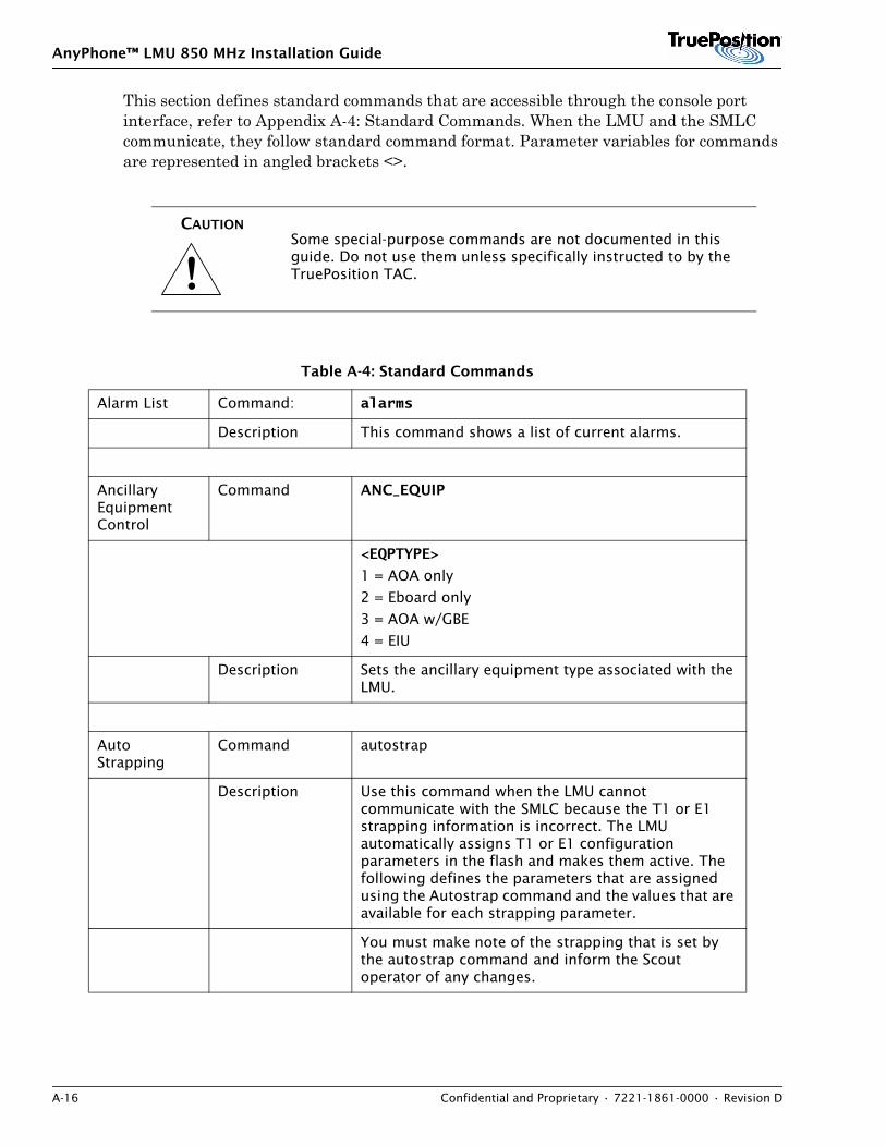
AnyPhone™ LMU 850 MHz Installation Guide
A-16 Confidential and Proprietary • 7221-1861-0000 • Revision D
This section defines standard commands that are accessible through the console port interface, refer to Appendix A-4: Standard Commands. When the LMU and the SMLC communicate, they follow standard command format. Parameter variables for commands are represented in angled brackets <>.
!CAUTION
Some special-purpose commands are not documented in this guide. Do not use them unless specifically instructed to by the TruePosition TAC.
Table A-4: Standard Commands
Alarm List Command: alarms
Description This command shows a list of current alarms.
Ancillary Equipment Control
Command ANC_EQUIP
<EQPTYPE>
1 = AOA only
2 = Eboard only
3 = AOA w/GBE
4 = EIU
Description Sets the ancillary equipment type associated with the LMU.
Auto Strapping
Command autostrap
Description Use this command when the LMU cannot communicate with the SMLC because the T1 or E1 strapping information is incorrect. The LMU automatically assigns T1 or E1 configuration parameters in the flash and makes them active. The following defines the parameters that are assigned using the Autostrap command and the values that are available for each strapping parameter.
You must make note of the strapping that is set by the autostrap command and inform the Scout operator of any changes.
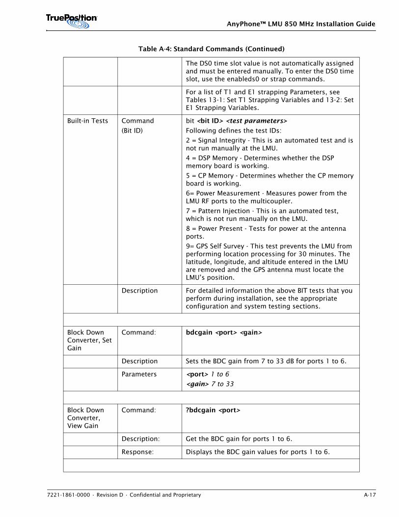
AnyPhone™ LMU 850 MHz Installation Guide
7221-1861-0000 • Revision D • Confidential and Proprietary A-17
The DS0 time slot value is not automatically assigned and must be entered manually. To enter the DS0 time slot, use the enableds0 or strap commands.
For a list of T1 and E1 strapping Parameters, see Tables 13-1: Set T1 Strapping Variables and 13-2: Set E1 Strapping Variables.
Built-in Tests Command
(Bit ID)
bit <bit ID> <test parameters>
Following defines the test IDs:
2 = Signal Integrity - This is an automated test and is not run manually at the LMU.
4 = DSP Memory - Determines whether the DSP memory board is working.
5 = CP Memory - Determines whether the CP memory board is working.
6= Power Measurement - Measures power from the LMU RF ports to the multicoupler.
7 = Pattern Injection - This is an automated test, which is not run manually on the LMU.
8 = Power Present - Tests for power at the antenna ports.
9= GPS Self Survey - This test prevents the LMU from performing location processing for 30 minutes. The latitude, longitude, and altitude entered in the LMU are removed and the GPS antenna must locate the LMU’s position.
Description For detailed information the above BIT tests that you perform during installation, see the appropriate configuration and system testing sections.
Block Down Converter, Set Gain
Command: bdcgain <port> <gain>
Description Sets the BDC gain from 7 to 33 dB for ports 1 to 6.
Parameters <port> 1 to 6
<gain> 7 to 33
Block Down Converter, View Gain
Command: ?bdcgain <port>
Description: Get the BDC gain for ports 1 to 6.
Response: Displays the BDC gain values for ports 1 to 6.
Table A-4: Standard Commands (Continued)
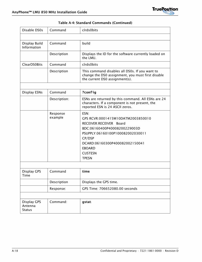
AnyPhone™ LMU 850 MHz Installation Guide
A-18 Confidential and Proprietary • 7221-1861-0000 • Revision D
Disable DS0s Command clrds0bits
Display Build Information
Command build
Description Displays the ID for the software currently loaded on the LMU.
ClearDS0Bits Command clrds0bits
Description This command disables all DS0s. If you want to change the DS0 assignment, you must first disable the current DS0 assignment(s).
Display ESNs Command ?config
Description: ESNs are returned by this command. All ESNs are 24 characters. If a component is not present, the reported ESN is 24 ASCII zeros.
Response example
ESN:
GPS RCVR:0001415M10DATM2003850010
RECEIVER:RECEIVER Board
BDC:06160400P40008200229003D
PSUPPLY:06160100P100082002030011
CP/DSP
DCARD:06160300P400082002150041
EBOARD
CUSTESN
TPESN
Display GPS Time
Command time
Description Displays the GPS time.
Response: GPS Time: 706652080.00 seconds
Display GPS Antenna Status
Command: gstat:
Table A-4: Standard Commands (Continued)
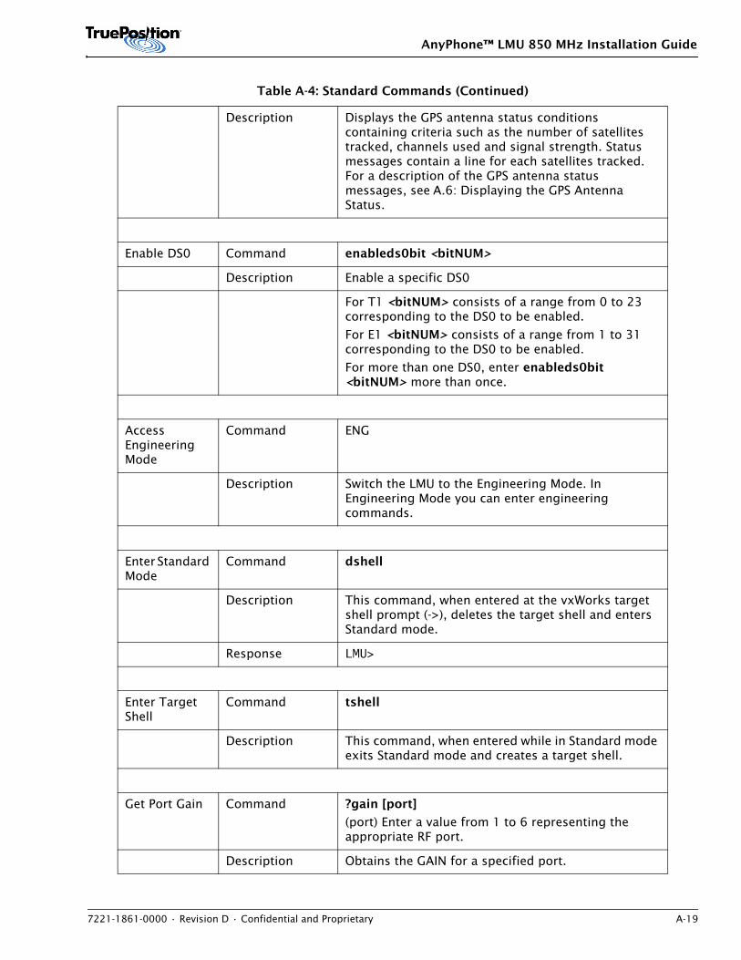
AnyPhone™ LMU 850 MHz Installation Guide
7221-1861-0000 • Revision D • Confidential and Proprietary A-19
Description Displays the GPS antenna status conditions containing criteria such as the number of satellites tracked, channels used and signal strength. Status messages contain a line for each satellites tracked. For a description of the GPS antenna status messages, see A.6: Displaying the GPS Antenna Status.
Enable DS0 Command enableds0bit <bitNUM>
Description Enable a specific DS0
For T1 <bitNUM> consists of a range from 0 to 23 corresponding to the DS0 to be enabled.
For E1 <bitNUM> consists of a range from 1 to 31 corresponding to the DS0 to be enabled.
For more than one DS0, enter enableds0bit <bitNUM> more than once.
Access Engineering Mode
Command ENG
Description Switch the LMU to the Engineering Mode. In Engineering Mode you can enter engineering commands.
Enter Standard Mode
Command dshell
Description This command, when entered at the vxWorks target shell prompt (->), deletes the target shell and enters Standard mode.
Response LMU>
Enter Target Shell
Command tshell
Description This command, when entered while in Standard mode exits Standard mode and creates a target shell.
Get Port Gain Command ?gain [port]
(port) Enter a value from 1 to 6 representing the appropriate RF port.
Description Obtains the GAIN for a specified port.
Table A-4: Standard Commands (Continued)
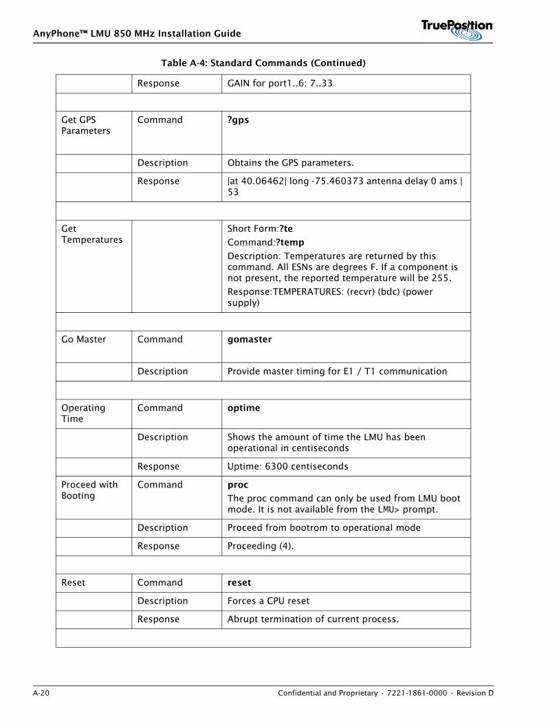
AnyPhone™ LMU 850 MHz Installation Guide
A-20 Confidential and Proprietary • 7221-1861-0000 • Revision D
Response GAIN for port1..6: 7..33
Get GPS Parameters
Command ?gps
Description Obtains the GPS parameters.
Response |at 40.06462| long -75.460373 antenna delay 0 ams | 53
Get Temperatures
Short Form:?te
Command:?temp
Description: Temperatures are returned by this command. All ESNs are degrees F. If a component is not present, the reported temperature will be 255.
Response:TEMPERATURES: (recvr) (bdc) (power supply)
Go Master Command gomaster
Description Provide master timing for E1 / T1 communication
Operating Time
Command optime
Description Shows the amount of time the LMU has been operational in centiseconds
Response Uptime: 6300 centiseconds
Proceed with Booting
Command proc
The proc command can only be used from LMU boot mode. It is not available from the LMU> prompt.
Description Proceed from bootrom to operational mode
Response Proceeding (4).
Reset Command reset
Description Forces a CPU reset
Response Abrupt termination of current process.
Table A-4: Standard Commands (Continued)
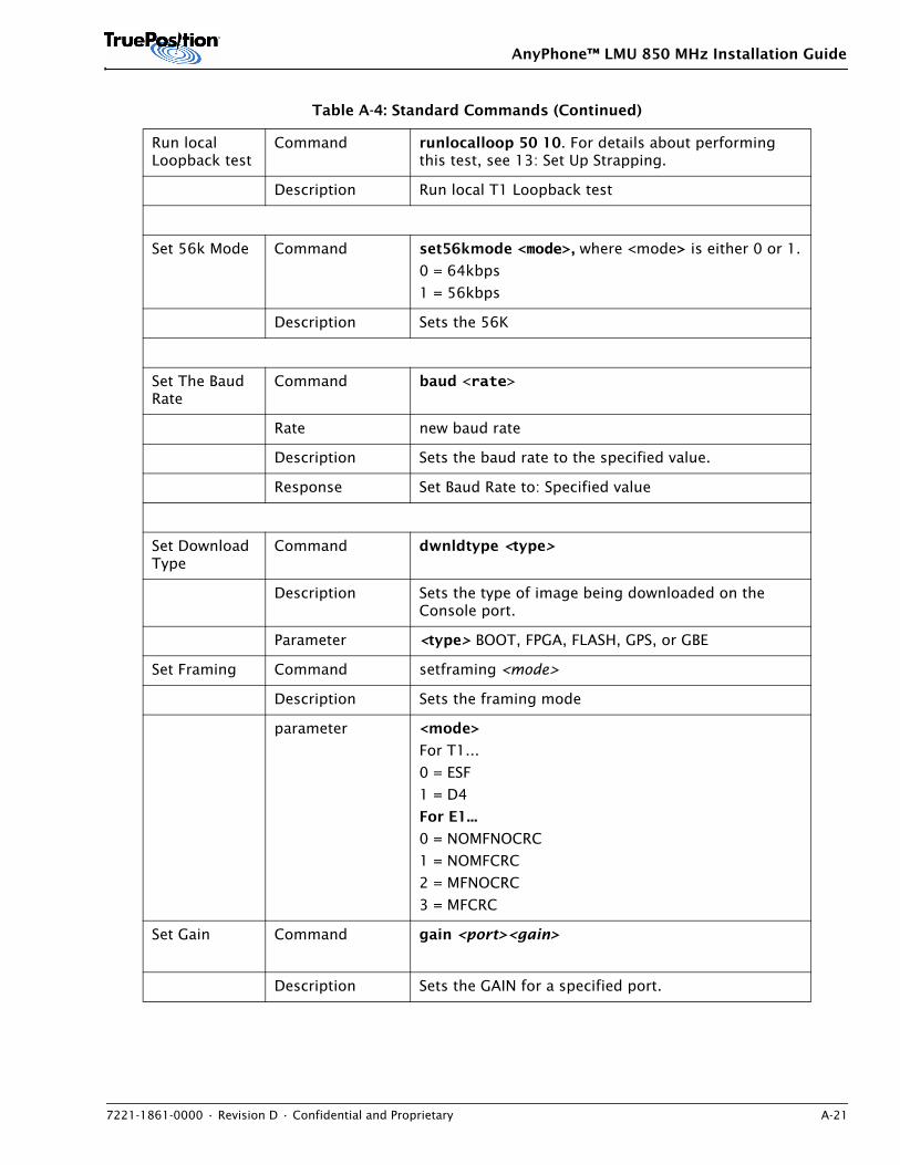
AnyPhone™ LMU 850 MHz Installation Guide
7221-1861-0000 • Revision D • Confidential and Proprietary A-21
Run local Loopback test
Command runlocalloop 50 10. For details about performing this test, see 13: Set Up Strapping.
Description Run local T1 Loopback test
Set 56k Mode Command set56kmode <mode>, where <mode> is either 0 or 1.
0 = 64kbps
1 = 56kbps
Description Sets the 56K
Set The Baud Rate
Command baud <rate>
Rate new baud rate
Description Sets the baud rate to the specified value.
Response Set Baud Rate to: Specified value
Set Download Type
Command dwnldtype <type>
Description Sets the type of image being downloaded on the Console port.
Parameter <type> BOOT, FPGA, FLASH, GPS, or GBE
Set Framing Command setframing <mode>
Description Sets the framing mode
parameter <mode>
For T1...
0 = ESF
1 = D4
For E1...
0 = NOMFNOCRC
1 = NOMFCRC
2 = MFNOCRC
3 = MFCRC
Set Gain Command gain <port><gain>
Description Sets the GAIN for a specified port.
Table A-4: Standard Commands (Continued)
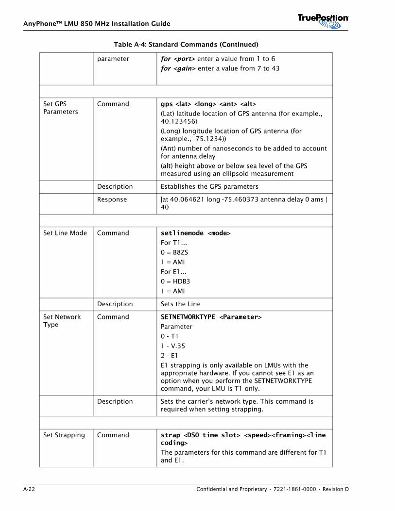
AnyPhone™ LMU 850 MHz Installation Guide
A-22 Confidential and Proprietary • 7221-1861-0000 • Revision D
parameter for <port> enter a value from 1 to 6
for <gain> enter a value from 7 to 43
Set GPS Parameters
Command gps <lat> <long> <ant> <alt>
(Lat) latitude location of GPS antenna (for example., 40.123456)
(Long) longitude location of GPS antenna (for example., -75.1234))
(Ant) number of nanoseconds to be added to account for antenna delay
(alt) height above or below sea level of the GPS measured using an ellipsoid measurement
Description Establishes the GPS parameters
Response |at 40.064621 long -75.460373 antenna delay 0 ams | 40
Set Line Mode Command setlinemode <mode>
For T1...
0 = B8ZS
1 = AMI
For E1...
0 = HDB3
1 = AMI
Description Sets the Line
Set Network Type
Command SETNETWORKTYPE <Parameter>
Parameter
0 - T1
1 - V.35
2 - E1
E1 strapping is only available on LMUs with the appropriate hardware. If you cannot see E1 as an option when you perform the SETNETWORKTYPE command, your LMU is T1 only.
Description Sets the carrier’s network type. This command is required when setting strapping.
Set Strapping Command strap <DS0 time slot> <speed><framing><line coding>
The parameters for this command are different for T1 and E1.
Table A-4: Standard Commands (Continued)
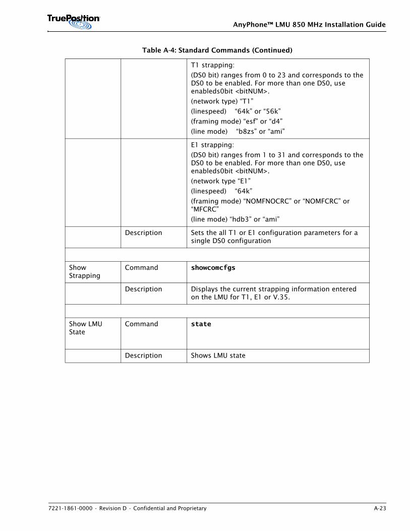
AnyPhone™ LMU 850 MHz Installation Guide
7221-1861-0000 • Revision D • Confidential and Proprietary A-23
T1 strapping:
(DS0 bit) ranges from 0 to 23 and corresponds to the DS0 to be enabled. For more than one DS0, use enableds0bit <bitNUM>.
(network type) “T1”
(linespeed) “64k” or “56k”
(framing mode) “esf” or “d4”
(line mode) “b8zs” or “ami”
E1 strapping:
(DS0 bit) ranges from 1 to 31 and corresponds to the DS0 to be enabled. For more than one DS0, use enableds0bit <bitNUM>.
(network type “E1”
(linespeed) “64k”
(framing mode) “NOMFNOCRC” or “NOMFCRC” or “MFCRC”
(line mode) “hdb3” or “ami”
Description Sets the all T1 or E1 configuration parameters for a single DS0 configuration
Show Strapping
Command showcomcfgs
Description Displays the current strapping information entered on the LMU for T1, E1 or V.35.
Show LMU State
Command state
Description Shows LMU state
Table A-4: Standard Commands (Continued)
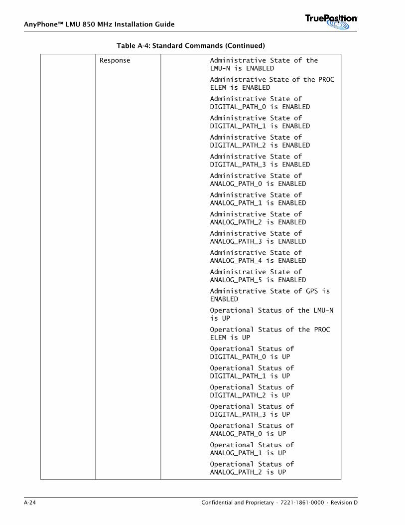
AnyPhone™ LMU 850 MHz Installation Guide
A-24 Confidential and Proprietary • 7221-1861-0000 • Revision D
Response Administrative State of the LMU-N is ENABLED
Administrative State of the PROC ELEM is ENABLED
Administrative State of DIGITAL_PATH_0 is ENABLED
Administrative State of DIGITAL_PATH_1 is ENABLED
Administrative State of DIGITAL_PATH_2 is ENABLED
Administrative State of DIGITAL_PATH_3 is ENABLED
Administrative State of ANALOG_PATH_0 is ENABLED
Administrative State of ANALOG_PATH_1 is ENABLED
Administrative State of ANALOG_PATH_2 is ENABLED
Administrative State of ANALOG_PATH_3 is ENABLED
Administrative State of ANALOG_PATH_4 is ENABLED
Administrative State of ANALOG_PATH_5 is ENABLED
Administrative State of GPS is ENABLED
Operational Status of the LMU-N is UP
Operational Status of the PROC ELEM is UP
Operational Status of DIGITAL_PATH_0 is UP
Operational Status of DIGITAL_PATH_1 is UP
Operational Status of DIGITAL_PATH_2 is UP
Operational Status of DIGITAL_PATH_3 is UP
Operational Status of ANALOG_PATH_0 is UP
Operational Status of ANALOG_PATH_1 is UP
Operational Status of ANALOG_PATH_2 is UP
Table A-4: Standard Commands (Continued)
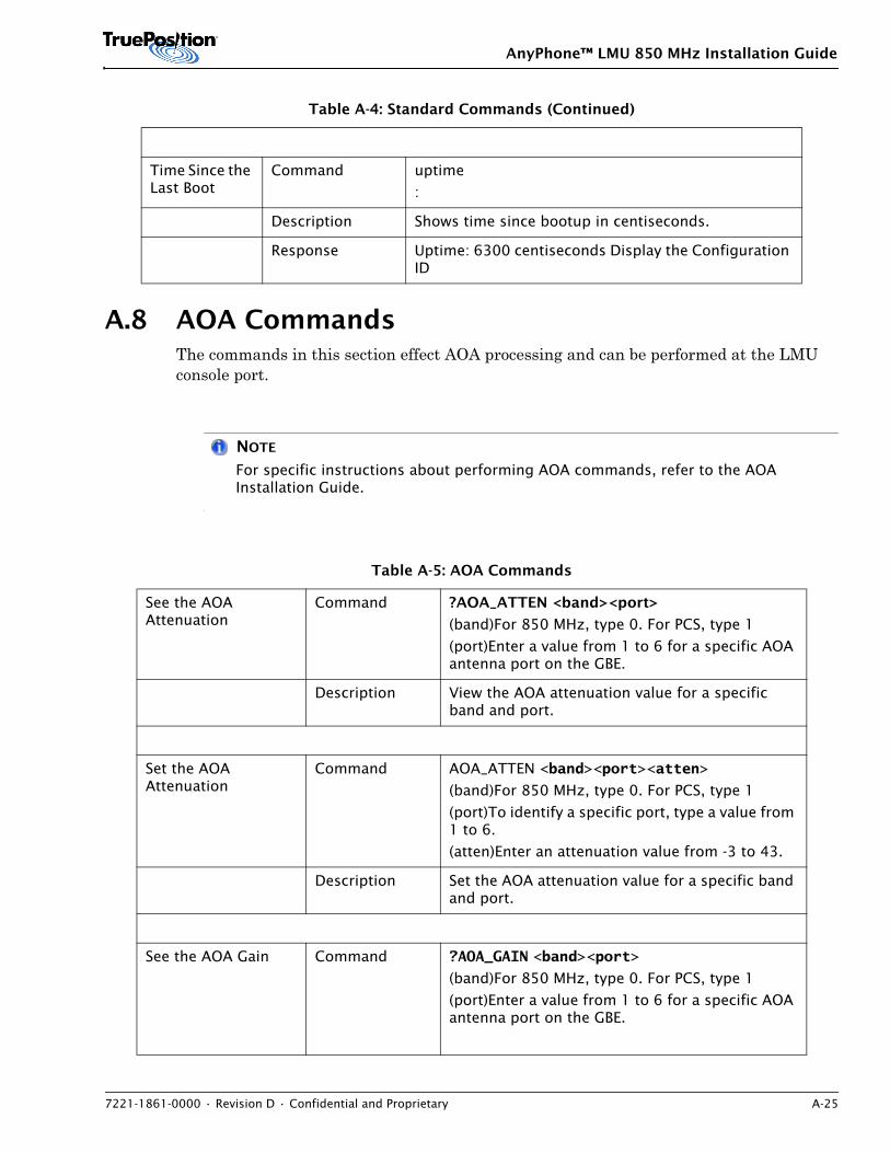
AnyPhone™ LMU 850 MHz Installation Guide
7221-1861-0000 • Revision D • Confidential and Proprietary A-25
A.8 AOA CommandsThe commands in this section effect AOA processing and can be performed at the LMU console port.
NOTE
For specific instructions about performing AOA commands, refer to the AOA Installation Guide.
Time Since the Last Boot
Command uptime
:
Description Shows time since bootup in centiseconds.
Response Uptime: 6300 centiseconds Display the Configuration ID
Table A-5: AOA Commands
See the AOA Attenuation
Command ?AOA_ATTEN <band><port>
(band)For 850 MHz, type 0. For PCS, type 1
(port)Enter a value from 1 to 6 for a specific AOA antenna port on the GBE.
Description View the AOA attenuation value for a specific band and port.
Set the AOA Attenuation
Command AOA_ATTEN <band><port><atten>
(band)For 850 MHz, type 0. For PCS, type 1
(port)To identify a specific port, type a value from 1 to 6.
(atten)Enter an attenuation value from -3 to 43.
Description Set the AOA attenuation value for a specific band and port.
See the AOA Gain Command ?AOA_GAIN <band><port>
(band)For 850 MHz, type 0. For PCS, type 1
(port)Enter a value from 1 to 6 for a specific AOA antenna port on the GBE.
Table A-4: Standard Commands (Continued)
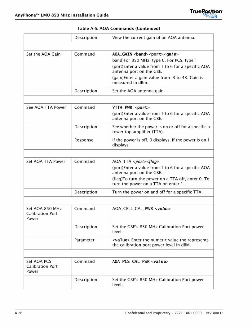
AnyPhone™ LMU 850 MHz Installation Guide
A-26 Confidential and Proprietary • 7221-1861-0000 • Revision D
Description View the current gain of an AOA antenna.
Set the AOA Gain Command AOA_GAIN <band><port><gain>
band)For 850 MHz, type 0. For PCS, type 1
(port)Enter a value from 1 to 6 for a specific AOA antenna port on the GBE.
(gain)Enter a gain value from -3 to 43. Gain is measured in dBm.
Description Set the AOA antenna gain.
See AOA TTA Power Command ?TTA_PWR <port>
(port)Enter a value from 1 to 6 for a specific AOA antenna port on the GBE.
Description See whether the power is on or off for a specific a tower top amplifier (TTA).
Response If the power is off, 0 displays. If the power is on 1 displays.
Set AOA TTA Power Command AOA_TTA <port><flag>
(port)Enter a value from 1 to 6 for a specific AOA antenna port on the GBE.
(flag)To turn the power on a TTA off, enter 0. To turn the power on a TTA on enter 1.
Description Turn the power on and off for a specific TTA.
Set AOA 850 MHz Calibration Port Power
Command AOA_CELL_CAL_PWR <value>
Description Set the GBE’s 850 MHz Calibration Port power level.
Parameter <value> Enter the numeric value the represents the calibration port power level in dBM.
Set AOA PCS Calibration Port Power
Command AOA_PCS_CAL_PWR <value>
Description Set the GBE’s 850 MHz Calibration Port power level.
Table A-5: AOA Commands (Continued)
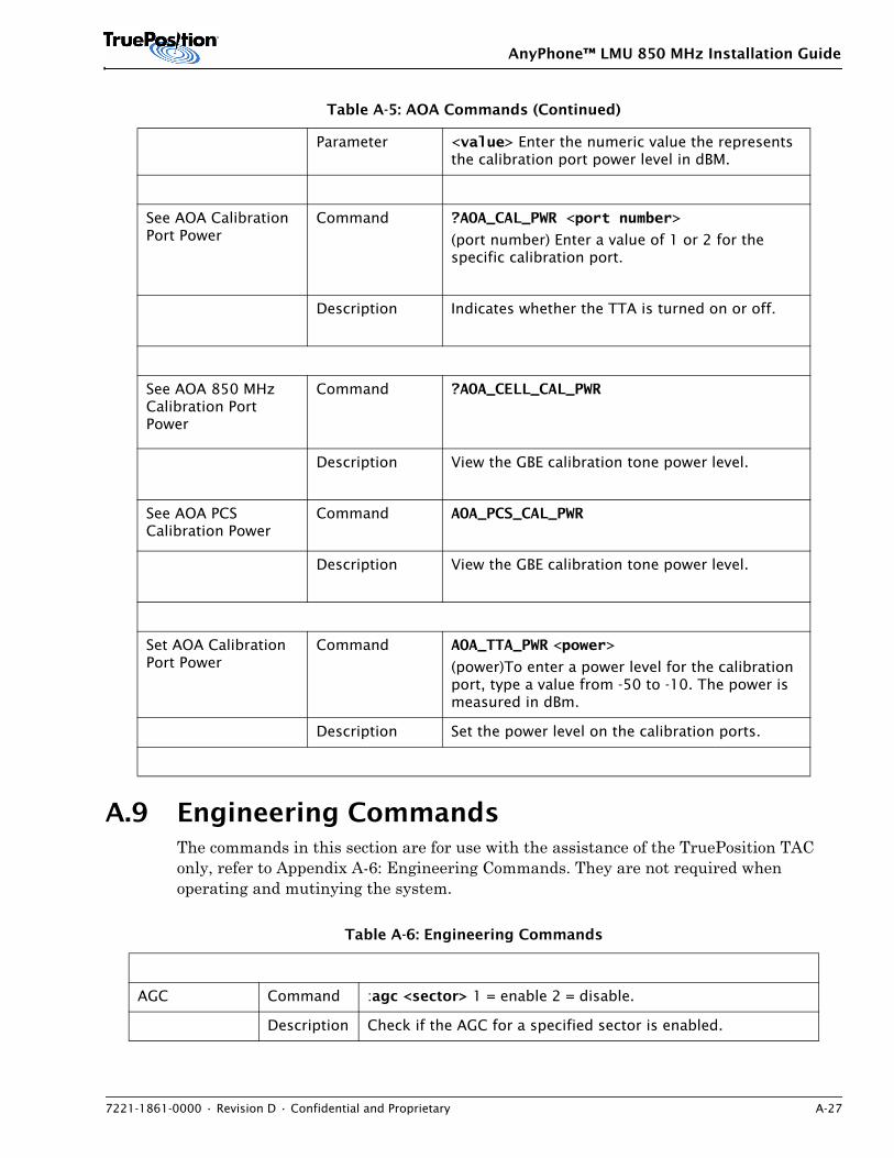
AnyPhone™ LMU 850 MHz Installation Guide
7221-1861-0000 • Revision D • Confidential and Proprietary A-27
A.9 Engineering CommandsThe commands in this section are for use with the assistance of the TruePosition TAC only, refer to Appendix A-6: Engineering Commands. They are not required when operating and mutinying the system.
Parameter <value> Enter the numeric value the represents the calibration port power level in dBM.
See AOA Calibration Port Power
Command ?AOA_CAL_PWR <port number>
(port number) Enter a value of 1 or 2 for the specific calibration port.
Description Indicates whether the TTA is turned on or off.
See AOA 850 MHz Calibration Port Power
Command ?AOA_CELL_CAL_PWR
Description View the GBE calibration tone power level.
See AOA PCS Calibration Power
Command AOA_PCS_CAL_PWR
Description View the GBE calibration tone power level.
Set AOA Calibration Port Power
Command AOA_TTA_PWR <power>
(power)To enter a power level for the calibration port, type a value from -50 to -10. The power is measured in dBm.
Description Set the power level on the calibration ports.
Table A-6: Engineering Commands
AGC Command :agc <sector> 1 = enable 2 = disable.
Description Check if the AGC for a specified sector is enabled.
Table A-5: AOA Commands (Continued)
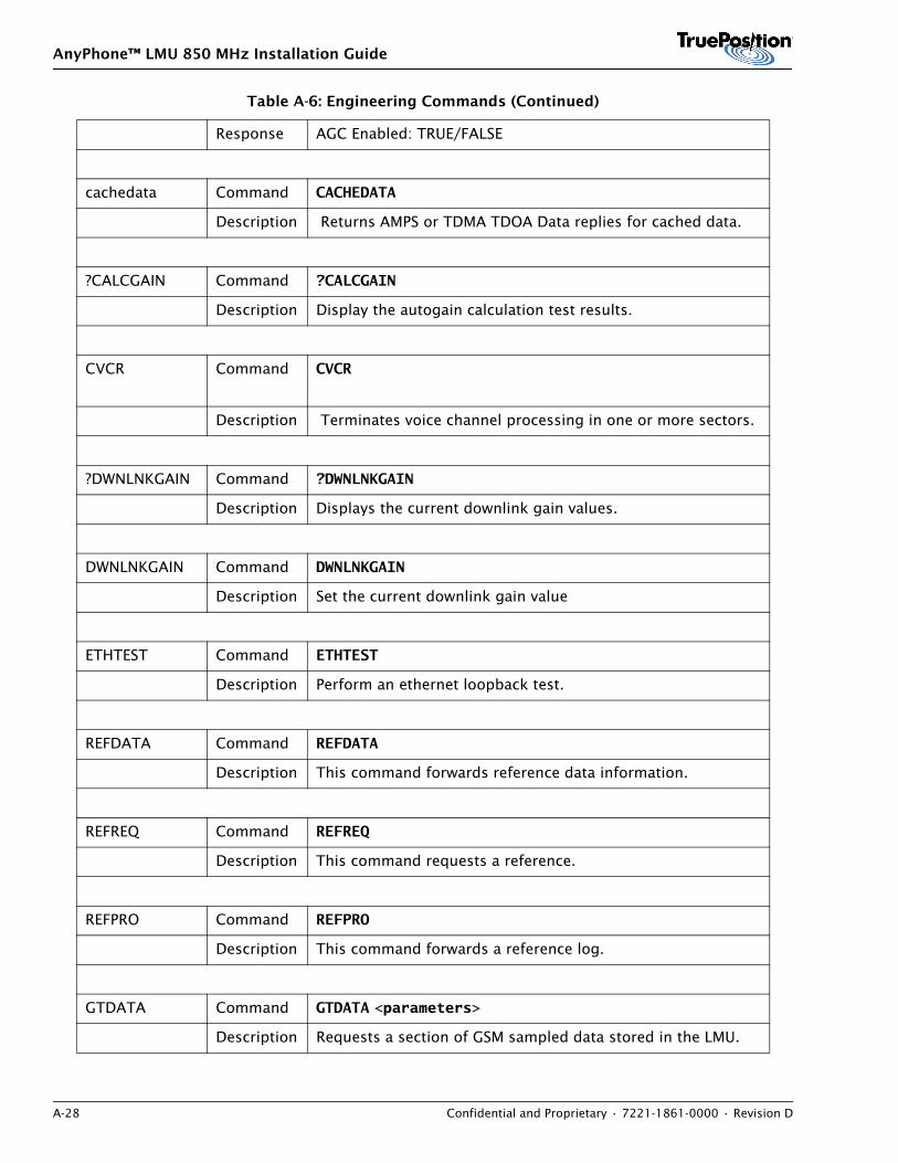
AnyPhone™ LMU 850 MHz Installation Guide
A-28 Confidential and Proprietary • 7221-1861-0000 • Revision D
Response AGC Enabled: TRUE/FALSE
cachedata Command CACHEDATA
Description Returns AMPS or TDMA TDOA Data replies for cached data.
?CALCGAIN Command ?CALCGAIN
Description Display the autogain calculation test results.
CVCR Command CVCR
Description Terminates voice channel processing in one or more sectors.
?DWNLNKGAIN Command ?DWNLNKGAIN
Description Displays the current downlink gain values.
DWNLNKGAIN Command DWNLNKGAIN
Description Set the current downlink gain value
ETHTEST Command ETHTEST
Description Perform an ethernet loopback test.
REFDATA Command REFDATA
Description This command forwards reference data information.
REFREQ Command REFREQ
Description This command requests a reference.
REFPRO Command REFPRO
Description This command forwards a reference log.
GTDATA Command GTDATA <parameters>
Description Requests a section of GSM sampled data stored in the LMU.
Table A-6: Engineering Commands (Continued)
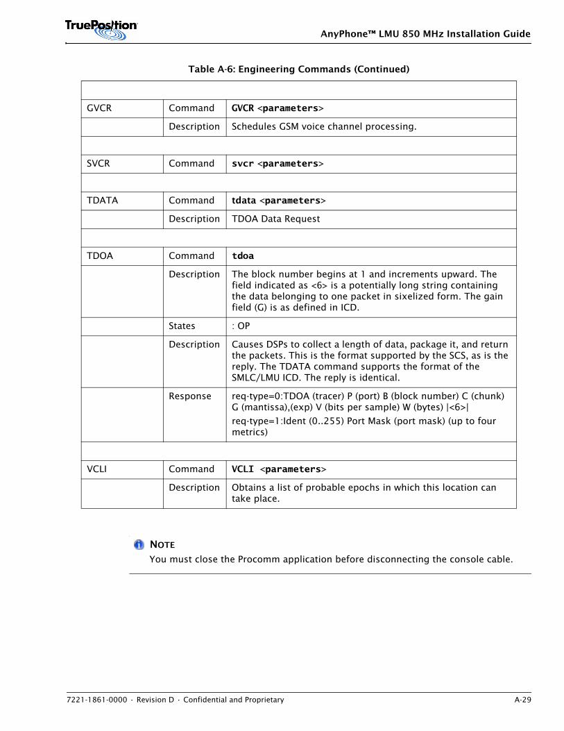
AnyPhone™ LMU 850 MHz Installation Guide
7221-1861-0000 • Revision D • Confidential and Proprietary A-29
NOTE
You must close the Procomm application before disconnecting the console cable.
GVCR Command GVCR <parameters>
Description Schedules GSM voice channel processing.
SVCR Command svcr <parameters>
TDATA Command tdata <parameters>
Description TDOA Data Request
TDOA Command tdoa
Description The block number begins at 1 and increments upward. The field indicated as <6> is a potentially long string containing the data belonging to one packet in sixelized form. The gain field (G) is as defined in ICD.
States : OP
Description Causes DSPs to collect a length of data, package it, and return the packets. This is the format supported by the SCS, as is the reply. The TDATA command supports the format of the SMLC/LMU ICD. The reply is identical.
Response req-type=0:TDOA (tracer) P (port) B (block number) C (chunk) G (mantissa),(exp) V (bits per sample) W (bytes) |<6>|
req-type=1:Ident (0..255) Port Mask (port mask) (up to four metrics)
VCLI Command VCLI <parameters>
Description Obtains a list of probable epochs in which this location can take place.
Table A-6: Engineering Commands (Continued)

AnyPhone™ LMU 850 MHz Installation Guide
A-30 Confidential and Proprietary • 7221-1861-0000 • Revision D
AnyPhone ™ LMU 850 / 1900 MHz Dual Band Installation Guide
7221-1862-0000 • Revision D • Confidential and Proprietary B-1
APPENDIX B. DUAL BAND CABLE SELECTION TABLES
ContentsB.1 Overview . . . . . . . . . . . . . . . . . . . . . . . . . . . . . . . . . . . . . . . . . . . . . . . . . . . . . . . . . . . . . B-1B.2 Using the Tables . . . . . . . . . . . . . . . . . . . . . . . . . . . . . . . . . . . . . . . . . . . . . . . . . . . . . . . B-1
B.1 OverviewThis appendix contains tables for selecting cables based on the measured gain at the multicoupler, combined with the length of the cable between the multicoupler and the AnyPhone LMU. The following tables appear:
• 850 MHz RF antennas
• 1900 MHz RF antennas
Use the chart for the correct frequency connection on the LMU. That the tables apply for two cable types.
• RG8X cable
• FSJ2 cable
NOTE
The charts are blank for any situation where the combination of multicoupler gain and cable length is outside the capabilities of both types of cables. For those situations, call the TruePosition Technical Assistance Center (TAC) for advice on what cable to use.
B.2 Using the TablesFollow the instructions in 5.4: Select Cables to determine the cable length and multicoupler gain for each cable. Use those two figures to locate the cell in the table where the multicoupler gain column intersects the row for the length of cable. Use the indicated cable type for fabricating this cable
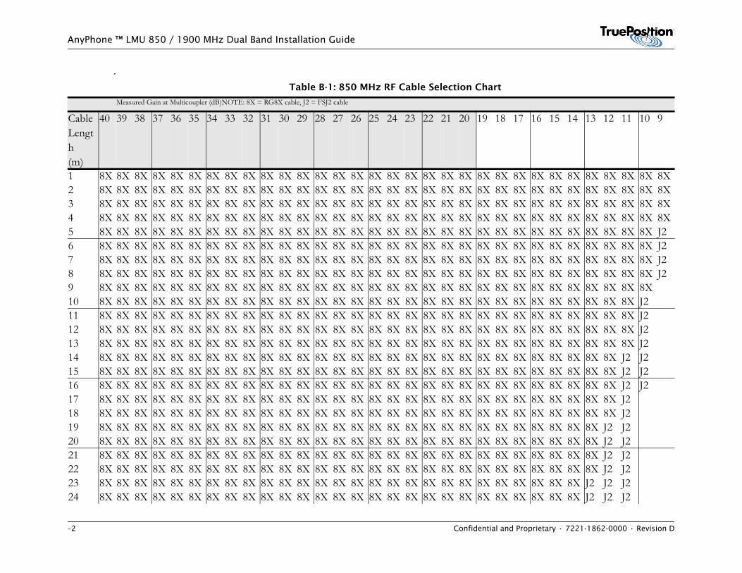
–2 Confidential and Proprietary • 7221-1862-0000 • Revision D
AnyPhone ™ LMU 850 / 1900 MHz Dual Band Installation Guide
.Table B-1: 850 MHz RF Cable Selection Chart
Measured Gain at Multicoupler (dB)NOTE: 8X = RG8X cable, J2 = FSJ2 cable
Cable Length(m)
40 39 38 37 36 35 34 33 32 31 30 29 28 27 26 25 24 23 22 21 20 19 18 17 16 15 14 13 12 11 10 9
1 8X 8X 8X 8X 8X 8X 8X 8X 8X 8X 8X 8X 8X 8X 8X 8X 8X 8X 8X 8X 8X 8X 8X 8X 8X 8X 8X 8X 8X 8X 8X 8X2 8X 8X 8X 8X 8X 8X 8X 8X 8X 8X 8X 8X 8X 8X 8X 8X 8X 8X 8X 8X 8X 8X 8X 8X 8X 8X 8X 8X 8X 8X 8X 8X3 8X 8X 8X 8X 8X 8X 8X 8X 8X 8X 8X 8X 8X 8X 8X 8X 8X 8X 8X 8X 8X 8X 8X 8X 8X 8X 8X 8X 8X 8X 8X 8X4 8X 8X 8X 8X 8X 8X 8X 8X 8X 8X 8X 8X 8X 8X 8X 8X 8X 8X 8X 8X 8X 8X 8X 8X 8X 8X 8X 8X 8X 8X 8X 8X5 8X 8X 8X 8X 8X 8X 8X 8X 8X 8X 8X 8X 8X 8X 8X 8X 8X 8X 8X 8X 8X 8X 8X 8X 8X 8X 8X 8X 8X 8X 8X J26 8X 8X 8X 8X 8X 8X 8X 8X 8X 8X 8X 8X 8X 8X 8X 8X 8X 8X 8X 8X 8X 8X 8X 8X 8X 8X 8X 8X 8X 8X 8X J27 8X 8X 8X 8X 8X 8X 8X 8X 8X 8X 8X 8X 8X 8X 8X 8X 8X 8X 8X 8X 8X 8X 8X 8X 8X 8X 8X 8X 8X 8X 8X J28 8X 8X 8X 8X 8X 8X 8X 8X 8X 8X 8X 8X 8X 8X 8X 8X 8X 8X 8X 8X 8X 8X 8X 8X 8X 8X 8X 8X 8X 8X 8X J29 8X 8X 8X 8X 8X 8X 8X 8X 8X 8X 8X 8X 8X 8X 8X 8X 8X 8X 8X 8X 8X 8X 8X 8X 8X 8X 8X 8X 8X 8X 8X10 8X 8X 8X 8X 8X 8X 8X 8X 8X 8X 8X 8X 8X 8X 8X 8X 8X 8X 8X 8X 8X 8X 8X 8X 8X 8X 8X 8X 8X 8X J211 8X 8X 8X 8X 8X 8X 8X 8X 8X 8X 8X 8X 8X 8X 8X 8X 8X 8X 8X 8X 8X 8X 8X 8X 8X 8X 8X 8X 8X 8X J212 8X 8X 8X 8X 8X 8X 8X 8X 8X 8X 8X 8X 8X 8X 8X 8X 8X 8X 8X 8X 8X 8X 8X 8X 8X 8X 8X 8X 8X 8X J213 8X 8X 8X 8X 8X 8X 8X 8X 8X 8X 8X 8X 8X 8X 8X 8X 8X 8X 8X 8X 8X 8X 8X 8X 8X 8X 8X 8X 8X 8X J214 8X 8X 8X 8X 8X 8X 8X 8X 8X 8X 8X 8X 8X 8X 8X 8X 8X 8X 8X 8X 8X 8X 8X 8X 8X 8X 8X 8X 8X J2 J215 8X 8X 8X 8X 8X 8X 8X 8X 8X 8X 8X 8X 8X 8X 8X 8X 8X 8X 8X 8X 8X 8X 8X 8X 8X 8X 8X 8X 8X J2 J216 8X 8X 8X 8X 8X 8X 8X 8X 8X 8X 8X 8X 8X 8X 8X 8X 8X 8X 8X 8X 8X 8X 8X 8X 8X 8X 8X 8X 8X J2 J217 8X 8X 8X 8X 8X 8X 8X 8X 8X 8X 8X 8X 8X 8X 8X 8X 8X 8X 8X 8X 8X 8X 8X 8X 8X 8X 8X 8X 8X J218 8X 8X 8X 8X 8X 8X 8X 8X 8X 8X 8X 8X 8X 8X 8X 8X 8X 8X 8X 8X 8X 8X 8X 8X 8X 8X 8X 8X 8X J219 8X 8X 8X 8X 8X 8X 8X 8X 8X 8X 8X 8X 8X 8X 8X 8X 8X 8X 8X 8X 8X 8X 8X 8X 8X 8X 8X 8X J2 J220 8X 8X 8X 8X 8X 8X 8X 8X 8X 8X 8X 8X 8X 8X 8X 8X 8X 8X 8X 8X 8X 8X 8X 8X 8X 8X 8X 8X J2 J221 8X 8X 8X 8X 8X 8X 8X 8X 8X 8X 8X 8X 8X 8X 8X 8X 8X 8X 8X 8X 8X 8X 8X 8X 8X 8X 8X 8X J2 J222 8X 8X 8X 8X 8X 8X 8X 8X 8X 8X 8X 8X 8X 8X 8X 8X 8X 8X 8X 8X 8X 8X 8X 8X 8X 8X 8X 8X J2 J223 8X 8X 8X 8X 8X 8X 8X 8X 8X 8X 8X 8X 8X 8X 8X 8X 8X 8X 8X 8X 8X 8X 8X 8X 8X 8X 8X J2 J2 J224 8X 8X 8X 8X 8X 8X 8X 8X 8X 8X 8X 8X 8X 8X 8X 8X 8X 8X 8X 8X 8X 8X 8X 8X 8X 8X 8X J2 J2 J2
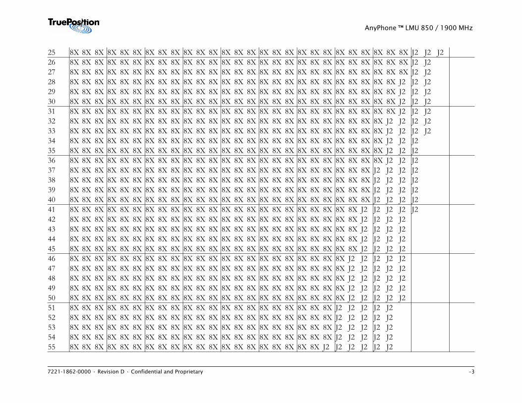
7221-1862-0000 • Revision D • Confidential and Proprietary –3
AnyPhone ™ LMU 850 / 1900 MHz
25 8X 8X 8X 8X 8X 8X 8X 8X 8X 8X 8X 8X 8X 8X 8X 8X 8X 8X 8X 8X 8X 8X 8X 8X 8X 8X 8X J2 J2 J226 8X 8X 8X 8X 8X 8X 8X 8X 8X 8X 8X 8X 8X 8X 8X 8X 8X 8X 8X 8X 8X 8X 8X 8X 8X 8X 8X J2 J227 8X 8X 8X 8X 8X 8X 8X 8X 8X 8X 8X 8X 8X 8X 8X 8X 8X 8X 8X 8X 8X 8X 8X 8X 8X 8X 8X J2 J228 8X 8X 8X 8X 8X 8X 8X 8X 8X 8X 8X 8X 8X 8X 8X 8X 8X 8X 8X 8X 8X 8X 8X 8X 8X 8X J2 J2 J229 8X 8X 8X 8X 8X 8X 8X 8X 8X 8X 8X 8X 8X 8X 8X 8X 8X 8X 8X 8X 8X 8X 8X 8X 8X 8X J2 J2 J230 8X 8X 8X 8X 8X 8X 8X 8X 8X 8X 8X 8X 8X 8X 8X 8X 8X 8X 8X 8X 8X 8X 8X 8X 8X 8X J2 J2 J231 8X 8X 8X 8X 8X 8X 8X 8X 8X 8X 8X 8X 8X 8X 8X 8X 8X 8X 8X 8X 8X 8X 8X 8X 8X 8X J2 J2 J232 8X 8X 8X 8X 8X 8X 8X 8X 8X 8X 8X 8X 8X 8X 8X 8X 8X 8X 8X 8X 8X 8X 8X 8X 8X J2 J2 J2 J233 8X 8X 8X 8X 8X 8X 8X 8X 8X 8X 8X 8X 8X 8X 8X 8X 8X 8X 8X 8X 8X 8X 8X 8X 8X J2 J2 J2 J234 8X 8X 8X 8X 8X 8X 8X 8X 8X 8X 8X 8X 8X 8X 8X 8X 8X 8X 8X 8X 8X 8X 8X 8X 8X J2 J2 J235 8X 8X 8X 8X 8X 8X 8X 8X 8X 8X 8X 8X 8X 8X 8X 8X 8X 8X 8X 8X 8X 8X 8X 8X 8X J2 J2 J236 8X 8X 8X 8X 8X 8X 8X 8X 8X 8X 8X 8X 8X 8X 8X 8X 8X 8X 8X 8X 8X 8X 8X 8X 8X J2 J2 J237 8X 8X 8X 8X 8X 8X 8X 8X 8X 8X 8X 8X 8X 8X 8X 8X 8X 8X 8X 8X 8X 8X 8X 8X J2 J2 J2 J238 8X 8X 8X 8X 8X 8X 8X 8X 8X 8X 8X 8X 8X 8X 8X 8X 8X 8X 8X 8X 8X 8X 8X 8X J2 J2 J2 J239 8X 8X 8X 8X 8X 8X 8X 8X 8X 8X 8X 8X 8X 8X 8X 8X 8X 8X 8X 8X 8X 8X 8X 8X J2 J2 J2 J240 8X 8X 8X 8X 8X 8X 8X 8X 8X 8X 8X 8X 8X 8X 8X 8X 8X 8X 8X 8X 8X 8X 8X 8X J2 J2 J2 J241 8X 8X 8X 8X 8X 8X 8X 8X 8X 8X 8X 8X 8X 8X 8X 8X 8X 8X 8X 8X 8X 8X 8X J2 J2 J2 J2 J242 8X 8X 8X 8X 8X 8X 8X 8X 8X 8X 8X 8X 8X 8X 8X 8X 8X 8X 8X 8X 8X 8X 8X J2 J2 J2 J243 8X 8X 8X 8X 8X 8X 8X 8X 8X 8X 8X 8X 8X 8X 8X 8X 8X 8X 8X 8X 8X 8X 8X J2 J2 J2 J244 8X 8X 8X 8X 8X 8X 8X 8X 8X 8X 8X 8X 8X 8X 8X 8X 8X 8X 8X 8X 8X 8X 8X J2 J2 J2 J245 8X 8X 8X 8X 8X 8X 8X 8X 8X 8X 8X 8X 8X 8X 8X 8X 8X 8X 8X 8X 8X 8X 8X J2 J2 J2 J246 8X 8X 8X 8X 8X 8X 8X 8X 8X 8X 8X 8X 8X 8X 8X 8X 8X 8X 8X 8X 8X 8X J2 J2 J2 J2 J247 8X 8X 8X 8X 8X 8X 8X 8X 8X 8X 8X 8X 8X 8X 8X 8X 8X 8X 8X 8X 8X 8X J2 J2 J2 J2 J248 8X 8X 8X 8X 8X 8X 8X 8X 8X 8X 8X 8X 8X 8X 8X 8X 8X 8X 8X 8X 8X 8X J2 J2 J2 J2 J249 8X 8X 8X 8X 8X 8X 8X 8X 8X 8X 8X 8X 8X 8X 8X 8X 8X 8X 8X 8X 8X 8X J2 J2 J2 J2 J250 8X 8X 8X 8X 8X 8X 8X 8X 8X 8X 8X 8X 8X 8X 8X 8X 8X 8X 8X 8X 8X 8X J2 J2 J2 J2 J251 8X 8X 8X 8X 8X 8X 8X 8X 8X 8X 8X 8X 8X 8X 8X 8X 8X 8X 8X 8X 8X J2 J2 J2 J2 J252 8X 8X 8X 8X 8X 8X 8X 8X 8X 8X 8X 8X 8X 8X 8X 8X 8X 8X 8X 8X 8X J2 J2 J2 J2 J253 8X 8X 8X 8X 8X 8X 8X 8X 8X 8X 8X 8X 8X 8X 8X 8X 8X 8X 8X 8X 8X J2 J2 J2 J2 J254 8X 8X 8X 8X 8X 8X 8X 8X 8X 8X 8X 8X 8X 8X 8X 8X 8X 8X 8X 8X 8X J2 J2 J2 J2 J255 8X 8X 8X 8X 8X 8X 8X 8X 8X 8X 8X 8X 8X 8X 8X 8X 8X 8X 8X 8X J2 J2 J2 J2 J2 J2
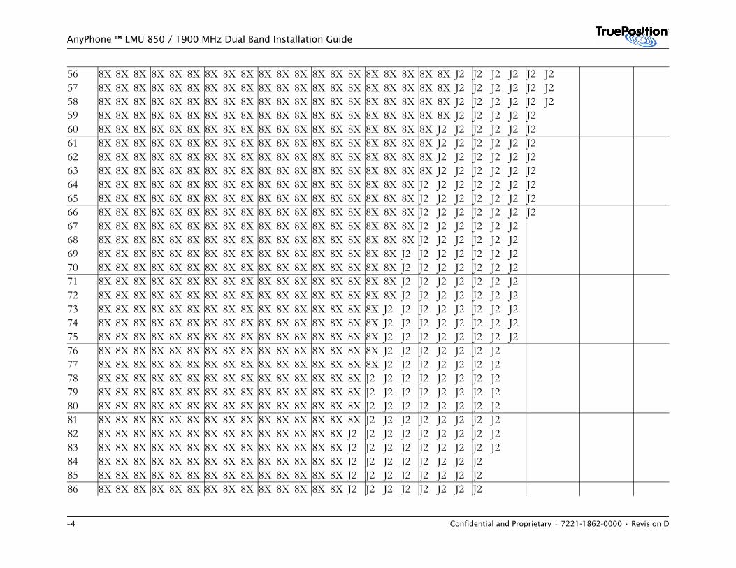
–4 Confidential and Proprietary • 7221-1862-0000 • Revision D
AnyPhone ™ LMU 850 / 1900 MHz Dual Band Installation Guide
56 8X 8X 8X 8X 8X 8X 8X 8X 8X 8X 8X 8X 8X 8X 8X 8X 8X 8X 8X 8X J2 J2 J2 J2 J2 J257 8X 8X 8X 8X 8X 8X 8X 8X 8X 8X 8X 8X 8X 8X 8X 8X 8X 8X 8X 8X J2 J2 J2 J2 J2 J258 8X 8X 8X 8X 8X 8X 8X 8X 8X 8X 8X 8X 8X 8X 8X 8X 8X 8X 8X 8X J2 J2 J2 J2 J2 J259 8X 8X 8X 8X 8X 8X 8X 8X 8X 8X 8X 8X 8X 8X 8X 8X 8X 8X 8X 8X J2 J2 J2 J2 J260 8X 8X 8X 8X 8X 8X 8X 8X 8X 8X 8X 8X 8X 8X 8X 8X 8X 8X 8X J2 J2 J2 J2 J2 J261 8X 8X 8X 8X 8X 8X 8X 8X 8X 8X 8X 8X 8X 8X 8X 8X 8X 8X 8X J2 J2 J2 J2 J2 J262 8X 8X 8X 8X 8X 8X 8X 8X 8X 8X 8X 8X 8X 8X 8X 8X 8X 8X 8X J2 J2 J2 J2 J2 J263 8X 8X 8X 8X 8X 8X 8X 8X 8X 8X 8X 8X 8X 8X 8X 8X 8X 8X 8X J2 J2 J2 J2 J2 J264 8X 8X 8X 8X 8X 8X 8X 8X 8X 8X 8X 8X 8X 8X 8X 8X 8X 8X J2 J2 J2 J2 J2 J2 J265 8X 8X 8X 8X 8X 8X 8X 8X 8X 8X 8X 8X 8X 8X 8X 8X 8X 8X J2 J2 J2 J2 J2 J2 J266 8X 8X 8X 8X 8X 8X 8X 8X 8X 8X 8X 8X 8X 8X 8X 8X 8X 8X J2 J2 J2 J2 J2 J2 J267 8X 8X 8X 8X 8X 8X 8X 8X 8X 8X 8X 8X 8X 8X 8X 8X 8X 8X J2 J2 J2 J2 J2 J268 8X 8X 8X 8X 8X 8X 8X 8X 8X 8X 8X 8X 8X 8X 8X 8X 8X 8X J2 J2 J2 J2 J2 J269 8X 8X 8X 8X 8X 8X 8X 8X 8X 8X 8X 8X 8X 8X 8X 8X 8X J2 J2 J2 J2 J2 J2 J270 8X 8X 8X 8X 8X 8X 8X 8X 8X 8X 8X 8X 8X 8X 8X 8X 8X J2 J2 J2 J2 J2 J2 J271 8X 8X 8X 8X 8X 8X 8X 8X 8X 8X 8X 8X 8X 8X 8X 8X 8X J2 J2 J2 J2 J2 J2 J272 8X 8X 8X 8X 8X 8X 8X 8X 8X 8X 8X 8X 8X 8X 8X 8X 8X J2 J2 J2 J2 J2 J2 J273 8X 8X 8X 8X 8X 8X 8X 8X 8X 8X 8X 8X 8X 8X 8X 8X J2 J2 J2 J2 J2 J2 J2 J274 8X 8X 8X 8X 8X 8X 8X 8X 8X 8X 8X 8X 8X 8X 8X 8X J2 J2 J2 J2 J2 J2 J2 J275 8X 8X 8X 8X 8X 8X 8X 8X 8X 8X 8X 8X 8X 8X 8X 8X J2 J2 J2 J2 J2 J2 J2 J276 8X 8X 8X 8X 8X 8X 8X 8X 8X 8X 8X 8X 8X 8X 8X 8X J2 J2 J2 J2 J2 J2 J277 8X 8X 8X 8X 8X 8X 8X 8X 8X 8X 8X 8X 8X 8X 8X 8X J2 J2 J2 J2 J2 J2 J278 8X 8X 8X 8X 8X 8X 8X 8X 8X 8X 8X 8X 8X 8X 8X J2 J2 J2 J2 J2 J2 J2 J279 8X 8X 8X 8X 8X 8X 8X 8X 8X 8X 8X 8X 8X 8X 8X J2 J2 J2 J2 J2 J2 J2 J280 8X 8X 8X 8X 8X 8X 8X 8X 8X 8X 8X 8X 8X 8X 8X J2 J2 J2 J2 J2 J2 J2 J281 8X 8X 8X 8X 8X 8X 8X 8X 8X 8X 8X 8X 8X 8X 8X J2 J2 J2 J2 J2 J2 J2 J282 8X 8X 8X 8X 8X 8X 8X 8X 8X 8X 8X 8X 8X 8X J2 J2 J2 J2 J2 J2 J2 J2 J283 8X 8X 8X 8X 8X 8X 8X 8X 8X 8X 8X 8X 8X 8X J2 J2 J2 J2 J2 J2 J2 J2 J284 8X 8X 8X 8X 8X 8X 8X 8X 8X 8X 8X 8X 8X 8X J2 J2 J2 J2 J2 J2 J2 J285 8X 8X 8X 8X 8X 8X 8X 8X 8X 8X 8X 8X 8X 8X J2 J2 J2 J2 J2 J2 J2 J286 8X 8X 8X 8X 8X 8X 8X 8X 8X 8X 8X 8X 8X 8X J2 J2 J2 J2 J2 J2 J2 J2
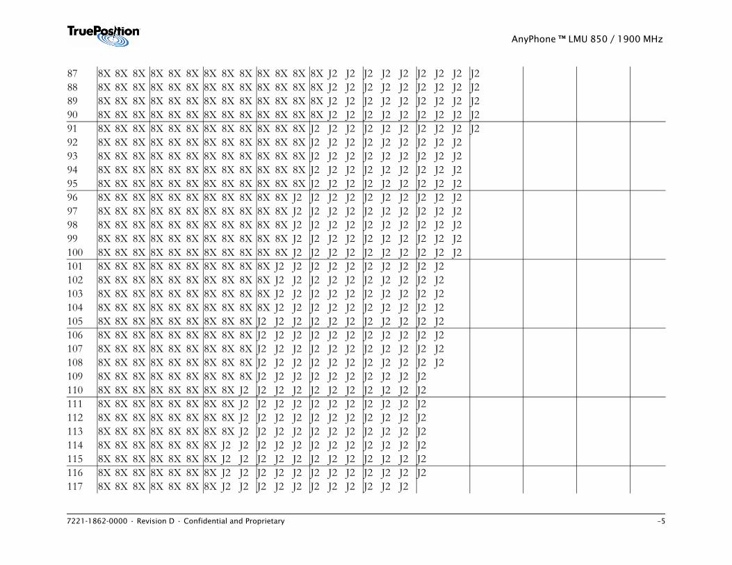
7221-1862-0000 • Revision D • Confidential and Proprietary –5
AnyPhone ™ LMU 850 / 1900 MHz
87 8X 8X 8X 8X 8X 8X 8X 8X 8X 8X 8X 8X 8X J2 J2 J2 J2 J2 J2 J2 J2 J288 8X 8X 8X 8X 8X 8X 8X 8X 8X 8X 8X 8X 8X J2 J2 J2 J2 J2 J2 J2 J2 J289 8X 8X 8X 8X 8X 8X 8X 8X 8X 8X 8X 8X 8X J2 J2 J2 J2 J2 J2 J2 J2 J290 8X 8X 8X 8X 8X 8X 8X 8X 8X 8X 8X 8X 8X J2 J2 J2 J2 J2 J2 J2 J2 J291 8X 8X 8X 8X 8X 8X 8X 8X 8X 8X 8X 8X J2 J2 J2 J2 J2 J2 J2 J2 J2 J292 8X 8X 8X 8X 8X 8X 8X 8X 8X 8X 8X 8X J2 J2 J2 J2 J2 J2 J2 J2 J293 8X 8X 8X 8X 8X 8X 8X 8X 8X 8X 8X 8X J2 J2 J2 J2 J2 J2 J2 J2 J294 8X 8X 8X 8X 8X 8X 8X 8X 8X 8X 8X 8X J2 J2 J2 J2 J2 J2 J2 J2 J295 8X 8X 8X 8X 8X 8X 8X 8X 8X 8X 8X 8X J2 J2 J2 J2 J2 J2 J2 J2 J296 8X 8X 8X 8X 8X 8X 8X 8X 8X 8X 8X J2 J2 J2 J2 J2 J2 J2 J2 J2 J297 8X 8X 8X 8X 8X 8X 8X 8X 8X 8X 8X J2 J2 J2 J2 J2 J2 J2 J2 J2 J298 8X 8X 8X 8X 8X 8X 8X 8X 8X 8X 8X J2 J2 J2 J2 J2 J2 J2 J2 J2 J299 8X 8X 8X 8X 8X 8X 8X 8X 8X 8X 8X J2 J2 J2 J2 J2 J2 J2 J2 J2 J2100 8X 8X 8X 8X 8X 8X 8X 8X 8X 8X 8X J2 J2 J2 J2 J2 J2 J2 J2 J2 J2101 8X 8X 8X 8X 8X 8X 8X 8X 8X 8X J2 J2 J2 J2 J2 J2 J2 J2 J2 J2102 8X 8X 8X 8X 8X 8X 8X 8X 8X 8X J2 J2 J2 J2 J2 J2 J2 J2 J2 J2103 8X 8X 8X 8X 8X 8X 8X 8X 8X 8X J2 J2 J2 J2 J2 J2 J2 J2 J2 J2104 8X 8X 8X 8X 8X 8X 8X 8X 8X 8X J2 J2 J2 J2 J2 J2 J2 J2 J2 J2105 8X 8X 8X 8X 8X 8X 8X 8X 8X J2 J2 J2 J2 J2 J2 J2 J2 J2 J2 J2106 8X 8X 8X 8X 8X 8X 8X 8X 8X J2 J2 J2 J2 J2 J2 J2 J2 J2 J2 J2107 8X 8X 8X 8X 8X 8X 8X 8X 8X J2 J2 J2 J2 J2 J2 J2 J2 J2 J2 J2108 8X 8X 8X 8X 8X 8X 8X 8X 8X J2 J2 J2 J2 J2 J2 J2 J2 J2 J2 J2109 8X 8X 8X 8X 8X 8X 8X 8X 8X J2 J2 J2 J2 J2 J2 J2 J2 J2 J2110 8X 8X 8X 8X 8X 8X 8X 8X J2 J2 J2 J2 J2 J2 J2 J2 J2 J2 J2111 8X 8X 8X 8X 8X 8X 8X 8X J2 J2 J2 J2 J2 J2 J2 J2 J2 J2 J2112 8X 8X 8X 8X 8X 8X 8X 8X J2 J2 J2 J2 J2 J2 J2 J2 J2 J2 J2113 8X 8X 8X 8X 8X 8X 8X 8X J2 J2 J2 J2 J2 J2 J2 J2 J2 J2 J2114 8X 8X 8X 8X 8X 8X 8X J2 J2 J2 J2 J2 J2 J2 J2 J2 J2 J2 J2115 8X 8X 8X 8X 8X 8X 8X J2 J2 J2 J2 J2 J2 J2 J2 J2 J2 J2 J2116 8X 8X 8X 8X 8X 8X 8X J2 J2 J2 J2 J2 J2 J2 J2 J2 J2 J2 J2117 8X 8X 8X 8X 8X 8X 8X J2 J2 J2 J2 J2 J2 J2 J2 J2 J2 J2
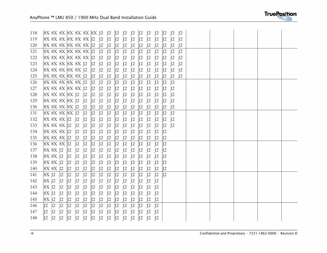
–6 Confidential and Proprietary • 7221-1862-0000 • Revision D
AnyPhone ™ LMU 850 / 1900 MHz Dual Band Installation Guide
118 8X 8X 8X 8X 8X 8X 8X J2 J2 J2 J2 J2 J2 J2 J2 J2 J2 J2119 8X 8X 8X 8X 8X 8X J2 J2 J2 J2 J2 J2 J2 J2 J2 J2 J2 J2120 8X 8X 8X 8X 8X 8X J2 J2 J2 J2 J2 J2 J2 J2 J2 J2 J2 J2121 8X 8X 8X 8X 8X 8X J2 J2 J2 J2 J2 J2 J2 J2 J2 J2 J2 J2122 8X 8X 8X 8X 8X 8X J2 J2 J2 J2 J2 J2 J2 J2 J2 J2 J2 J2123 8X 8X 8X 8X 8X J2 J2 J2 J2 J2 J2 J2 J2 J2 J2 J2 J2 J2124 8X 8X 8X 8X 8X J2 J2 J2 J2 J2 J2 J2 J2 J2 J2 J2 J2 J2125 8X 8X 8X 8X 8X J2 J2 J2 J2 J2 J2 J2 J2 J2 J2 J2 J2 J2126 8X 8X 8X 8X 8X J2 J2 J2 J2 J2 J2 J2 J2 J2 J2 J2 J2127 8X 8X 8X 8X 8X J2 J2 J2 J2 J2 J2 J2 J2 J2 J2 J2 J2128 8X 8X 8X 8X J2 J2 J2 J2 J2 J2 J2 J2 J2 J2 J2 J2 J2129 8X 8X 8X 8X J2 J2 J2 J2 J2 J2 J2 J2 J2 J2 J2 J2 J2130 8X 8X 8X 8X J2 J2 J2 J2 J2 J2 J2 J2 J2 J2 J2 J2 J2131 8X 8X 8X 8X J2 J2 J2 J2 J2 J2 J2 J2 J2 J2 J2 J2 J2132 8X 8X 8X J2 J2 J2 J2 J2 J2 J2 J2 J2 J2 J2 J2 J2 J2133 8X 8X 8X J2 J2 J2 J2 J2 J2 J2 J2 J2 J2 J2 J2 J2 J2134 8X 8X 8X J2 J2 J2 J2 J2 J2 J2 J2 J2 J2 J2 J2 J2135 8X 8X 8X J2 J2 J2 J2 J2 J2 J2 J2 J2 J2 J2 J2 J2136 8X 8X 8X J2 J2 J2 J2 J2 J2 J2 J2 J2 J2 J2 J2 J2137 8X 8X J2 J2 J2 J2 J2 J2 J2 J2 J2 J2 J2 J2 J2 J2138 8X 8X J2 J2 J2 J2 J2 J2 J2 J2 J2 J2 J2 J2 J2 J2139 8X 8X J2 J2 J2 J2 J2 J2 J2 J2 J2 J2 J2 J2 J2 J2140 8X 8X J2 J2 J2 J2 J2 J2 J2 J2 J2 J2 J2 J2 J2 J2141 8X J2 J2 J2 J2 J2 J2 J2 J2 J2 J2 J2 J2 J2 J2 J2142 8X J2 J2 J2 J2 J2 J2 J2 J2 J2 J2 J2 J2 J2 J2143 8X J2 J2 J2 J2 J2 J2 J2 J2 J2 J2 J2 J2 J2 J2144 8X J2 J2 J2 J2 J2 J2 J2 J2 J2 J2 J2 J2 J2 J2145 8X J2 J2 J2 J2 J2 J2 J2 J2 J2 J2 J2 J2 J2 J2146 J2 J2 J2 J2 J2 J2 J2 J2 J2 J2 J2 J2 J2 J2 J2147 J2 J2 J2 J2 J2 J2 J2 J2 J2 J2 J2 J2 J2 J2 J2148 J2 J2 J2 J2 J2 J2 J2 J2 J2 J2 J2 J2 J2 J2 J2
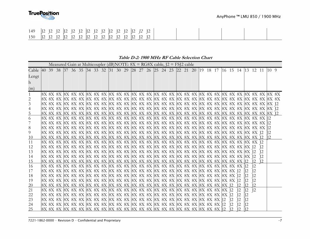
7221-1862-0000 • Revision D • Confidential and Proprietary –7
AnyPhone ™ LMU 850 / 1900 MHz
149 J2 J2 J2 J2 J2 J2 J2 J2 J2 J2 J2 J2 J2 J2 J2150 J2 J2 J2 J2 J2 J2 J2 J2 J2 J2 J2 J2 J2 J2 J2
Table D-2: 1900 MHz RF Cable Selection ChartMeasured Gain at Multicoupler (dB)NOTE: 8X = RG8X cable, J2 = FSJ2 cable
Cable Length(m)
40 39 38 37 36 35 34 33 32 31 30 29 28 27 26 25 24 23 22 21 20 19 18 17 16 15 14 13 12 11 10 9
1 8X 8X 8X 8X 8X 8X 8X 8X 8X 8X 8X 8X 8X 8X 8X 8X 8X 8X 8X 8X 8X 8X 8X 8X 8X 8X 8X 8X 8X 8X 8X 8X2 8X 8X 8X 8X 8X 8X 8X 8X 8X 8X 8X 8X 8X 8X 8X 8X 8X 8X 8X 8X 8X 8X 8X 8X 8X 8X 8X 8X 8X 8X 8X 8X3 8X 8X 8X 8X 8X 8X 8X 8X 8X 8X 8X 8X 8X 8X 8X 8X 8X 8X 8X 8X 8X 8X 8X 8X 8X 8X 8X 8X 8X 8X 8X J24 8X 8X 8X 8X 8X 8X 8X 8X 8X 8X 8X 8X 8X 8X 8X 8X 8X 8X 8X 8X 8X 8X 8X 8X 8X 8X 8X 8X 8X 8X 8X J25 8X 8X 8X 8X 8X 8X 8X 8X 8X 8X 8X 8X 8X 8X 8X 8X 8X 8X 8X 8X 8X 8X 8X 8X 8X 8X 8X 8X 8X 8X 8X J26 8X 8X 8X 8X 8X 8X 8X 8X 8X 8X 8X 8X 8X 8X 8X 8X 8X 8X 8X 8X 8X 8X 8X 8X 8X 8X 8X 8X 8X 8X J27 8X 8X 8X 8X 8X 8X 8X 8X 8X 8X 8X 8X 8X 8X 8X 8X 8X 8X 8X 8X 8X 8X 8X 8X 8X 8X 8X 8X 8X 8X J28 8X 8X 8X 8X 8X 8X 8X 8X 8X 8X 8X 8X 8X 8X 8X 8X 8X 8X 8X 8X 8X 8X 8X 8X 8X 8X 8X 8X 8X 8X J29 8X 8X 8X 8X 8X 8X 8X 8X 8X 8X 8X 8X 8X 8X 8X 8X 8X 8X 8X 8X 8X 8X 8X 8X 8X 8X 8X 8X 8X J2 J210 8X 8X 8X 8X 8X 8X 8X 8X 8X 8X 8X 8X 8X 8X 8X 8X 8X 8X 8X 8X 8X 8X 8X 8X 8X 8X 8X 8X 8X J2 J211 8X 8X 8X 8X 8X 8X 8X 8X 8X 8X 8X 8X 8X 8X 8X 8X 8X 8X 8X 8X 8X 8X 8X 8X 8X 8X 8X 8X 8X J212 8X 8X 8X 8X 8X 8X 8X 8X 8X 8X 8X 8X 8X 8X 8X 8X 8X 8X 8X 8X 8X 8X 8X 8X 8X 8X 8X 8X J2 J213 8X 8X 8X 8X 8X 8X 8X 8X 8X 8X 8X 8X 8X 8X 8X 8X 8X 8X 8X 8X 8X 8X 8X 8X 8X 8X 8X 8X J2 J214 8X 8X 8X 8X 8X 8X 8X 8X 8X 8X 8X 8X 8X 8X 8X 8X 8X 8X 8X 8X 8X 8X 8X 8X 8X 8X 8X 8X J2 J215 8X 8X 8X 8X 8X 8X 8X 8X 8X 8X 8X 8X 8X 8X 8X 8X 8X 8X 8X 8X 8X 8X 8X 8X 8X 8X 8X J2 J2 J216 8X 8X 8X 8X 8X 8X 8X 8X 8X 8X 8X 8X 8X 8X 8X 8X 8X 8X 8X 8X 8X 8X 8X 8X 8X 8X 8X J2 J217 8X 8X 8X 8X 8X 8X 8X 8X 8X 8X 8X 8X 8X 8X 8X 8X 8X 8X 8X 8X 8X 8X 8X 8X 8X 8X J2 J2 J218 8X 8X 8X 8X 8X 8X 8X 8X 8X 8X 8X 8X 8X 8X 8X 8X 8X 8X 8X 8X 8X 8X 8X 8X 8X 8X J2 J2 J219 8X 8X 8X 8X 8X 8X 8X 8X 8X 8X 8X 8X 8X 8X 8X 8X 8X 8X 8X 8X 8X 8X 8X 8X 8X 8X J2 J2 J220 8X 8X 8X 8X 8X 8X 8X 8X 8X 8X 8X 8X 8X 8X 8X 8X 8X 8X 8X 8X 8X 8X 8X 8X 8X J2 J2 J2 J221 8X 8X 8X 8X 8X 8X 8X 8X 8X 8X 8X 8X 8X 8X 8X 8X 8X 8X 8X 8X 8X 8X 8X 8X 8X J2 J2 J2 J222 8X 8X 8X 8X 8X 8X 8X 8X 8X 8X 8X 8X 8X 8X 8X 8X 8X 8X 8X 8X 8X 8X 8X 8X 8X J2 J2 J223 8X 8X 8X 8X 8X 8X 8X 8X 8X 8X 8X 8X 8X 8X 8X 8X 8X 8X 8X 8X 8X 8X 8X 8X J2 J2 J2 J224 8X 8X 8X 8X 8X 8X 8X 8X 8X 8X 8X 8X 8X 8X 8X 8X 8X 8X 8X 8X 8X 8X 8X 8X J2 J2 J2 J225 8X 8X 8X 8X 8X 8X 8X 8X 8X 8X 8X 8X 8X 8X 8X 8X 8X 8X 8X 8X 8X 8X 8X 8X J2 J2 J2 J2
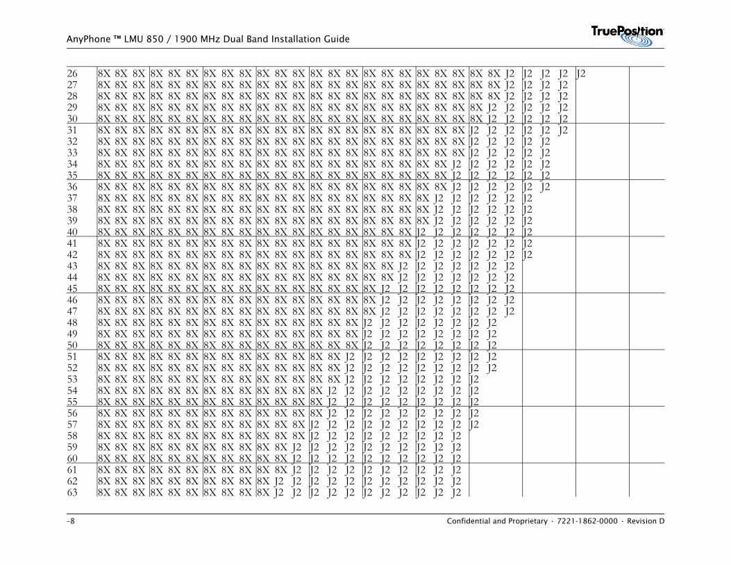
–8 Confidential and Proprietary • 7221-1862-0000 • Revision D
AnyPhone ™ LMU 850 / 1900 MHz Dual Band Installation Guide
26 8X 8X 8X 8X 8X 8X 8X 8X 8X 8X 8X 8X 8X 8X 8X 8X 8X 8X 8X 8X 8X 8X 8X J2 J2 J2 J2 J227 8X 8X 8X 8X 8X 8X 8X 8X 8X 8X 8X 8X 8X 8X 8X 8X 8X 8X 8X 8X 8X 8X 8X J2 J2 J2 J228 8X 8X 8X 8X 8X 8X 8X 8X 8X 8X 8X 8X 8X 8X 8X 8X 8X 8X 8X 8X 8X 8X 8X J2 J2 J2 J229 8X 8X 8X 8X 8X 8X 8X 8X 8X 8X 8X 8X 8X 8X 8X 8X 8X 8X 8X 8X 8X 8X J2 J2 J2 J2 J230 8X 8X 8X 8X 8X 8X 8X 8X 8X 8X 8X 8X 8X 8X 8X 8X 8X 8X 8X 8X 8X 8X J2 J2 J2 J2 J231 8X 8X 8X 8X 8X 8X 8X 8X 8X 8X 8X 8X 8X 8X 8X 8X 8X 8X 8X 8X 8X J2 J2 J2 J2 J2 J232 8X 8X 8X 8X 8X 8X 8X 8X 8X 8X 8X 8X 8X 8X 8X 8X 8X 8X 8X 8X 8X J2 J2 J2 J2 J233 8X 8X 8X 8X 8X 8X 8X 8X 8X 8X 8X 8X 8X 8X 8X 8X 8X 8X 8X 8X 8X J2 J2 J2 J2 J234 8X 8X 8X 8X 8X 8X 8X 8X 8X 8X 8X 8X 8X 8X 8X 8X 8X 8X 8X 8X J2 J2 J2 J2 J2 J235 8X 8X 8X 8X 8X 8X 8X 8X 8X 8X 8X 8X 8X 8X 8X 8X 8X 8X 8X 8X J2 J2 J2 J2 J2 J236 8X 8X 8X 8X 8X 8X 8X 8X 8X 8X 8X 8X 8X 8X 8X 8X 8X 8X 8X 8X J2 J2 J2 J2 J2 J237 8X 8X 8X 8X 8X 8X 8X 8X 8X 8X 8X 8X 8X 8X 8X 8X 8X 8X 8X J2 J2 J2 J2 J2 J238 8X 8X 8X 8X 8X 8X 8X 8X 8X 8X 8X 8X 8X 8X 8X 8X 8X 8X 8X J2 J2 J2 J2 J2 J239 8X 8X 8X 8X 8X 8X 8X 8X 8X 8X 8X 8X 8X 8X 8X 8X 8X 8X 8X J2 J2 J2 J2 J2 J240 8X 8X 8X 8X 8X 8X 8X 8X 8X 8X 8X 8X 8X 8X 8X 8X 8X 8X J2 J2 J2 J2 J2 J2 J241 8X 8X 8X 8X 8X 8X 8X 8X 8X 8X 8X 8X 8X 8X 8X 8X 8X 8X J2 J2 J2 J2 J2 J2 J242 8X 8X 8X 8X 8X 8X 8X 8X 8X 8X 8X 8X 8X 8X 8X 8X 8X 8X J2 J2 J2 J2 J2 J2 J243 8X 8X 8X 8X 8X 8X 8X 8X 8X 8X 8X 8X 8X 8X 8X 8X 8X J2 J2 J2 J2 J2 J2 J244 8X 8X 8X 8X 8X 8X 8X 8X 8X 8X 8X 8X 8X 8X 8X 8X 8X J2 J2 J2 J2 J2 J2 J245 8X 8X 8X 8X 8X 8X 8X 8X 8X 8X 8X 8X 8X 8X 8X 8X J2 J2 J2 J2 J2 J2 J2 J246 8X 8X 8X 8X 8X 8X 8X 8X 8X 8X 8X 8X 8X 8X 8X 8X J2 J2 J2 J2 J2 J2 J2 J247 8X 8X 8X 8X 8X 8X 8X 8X 8X 8X 8X 8X 8X 8X 8X 8X J2 J2 J2 J2 J2 J2 J2 J248 8X 8X 8X 8X 8X 8X 8X 8X 8X 8X 8X 8X 8X 8X 8X J2 J2 J2 J2 J2 J2 J2 J249 8X 8X 8X 8X 8X 8X 8X 8X 8X 8X 8X 8X 8X 8X 8X J2 J2 J2 J2 J2 J2 J2 J250 8X 8X 8X 8X 8X 8X 8X 8X 8X 8X 8X 8X 8X 8X 8X J2 J2 J2 J2 J2 J2 J2 J251 8X 8X 8X 8X 8X 8X 8X 8X 8X 8X 8X 8X 8X 8X J2 J2 J2 J2 J2 J2 J2 J2 J252 8X 8X 8X 8X 8X 8X 8X 8X 8X 8X 8X 8X 8X 8X J2 J2 J2 J2 J2 J2 J2 J2 J253 8X 8X 8X 8X 8X 8X 8X 8X 8X 8X 8X 8X 8X 8X J2 J2 J2 J2 J2 J2 J2 J254 8X 8X 8X 8X 8X 8X 8X 8X 8X 8X 8X 8X 8X J2 J2 J2 J2 J2 J2 J2 J2 J255 8X 8X 8X 8X 8X 8X 8X 8X 8X 8X 8X 8X 8X J2 J2 J2 J2 J2 J2 J2 J2 J256 8X 8X 8X 8X 8X 8X 8X 8X 8X 8X 8X 8X 8X J2 J2 J2 J2 J2 J2 J2 J2 J257 8X 8X 8X 8X 8X 8X 8X 8X 8X 8X 8X 8X J2 J2 J2 J2 J2 J2 J2 J2 J2 J258 8X 8X 8X 8X 8X 8X 8X 8X 8X 8X 8X 8X J2 J2 J2 J2 J2 J2 J2 J2 J259 8X 8X 8X 8X 8X 8X 8X 8X 8X 8X 8X J2 J2 J2 J2 J2 J2 J2 J2 J2 J260 8X 8X 8X 8X 8X 8X 8X 8X 8X 8X 8X J2 J2 J2 J2 J2 J2 J2 J2 J2 J261 8X 8X 8X 8X 8X 8X 8X 8X 8X 8X 8X J2 J2 J2 J2 J2 J2 J2 J2 J2 J262 8X 8X 8X 8X 8X 8X 8X 8X 8X 8X J2 J2 J2 J2 J2 J2 J2 J2 J2 J2 J263 8X 8X 8X 8X 8X 8X 8X 8X 8X 8X J2 J2 J2 J2 J2 J2 J2 J2 J2 J2 J2
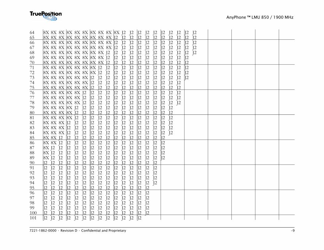
7221-1862-0000 • Revision D • Confidential and Proprietary –9
AnyPhone ™ LMU 850 / 1900 MHz
64 8X 8X 8X 8X 8X 8X 8X 8X 8X 8X J2 J2 J2 J2 J2 J2 J2 J2 J2 J265 8X 8X 8X 8X 8X 8X 8X 8X 8X J2 J2 J2 J2 J2 J2 J2 J2 J2 J2 J266 8X 8X 8X 8X 8X 8X 8X 8X 8X J2 J2 J2 J2 J2 J2 J2 J2 J2 J2 J267 8X 8X 8X 8X 8X 8X 8X 8X 8X J2 J2 J2 J2 J2 J2 J2 J2 J2 J2 J268 8X 8X 8X 8X 8X 8X 8X 8X J2 J2 J2 J2 J2 J2 J2 J2 J2 J2 J2 J269 8X 8X 8X 8X 8X 8X 8X 8X J2 J2 J2 J2 J2 J2 J2 J2 J2 J2 J270 8X 8X 8X 8X 8X 8X 8X 8X J2 J2 J2 J2 J2 J2 J2 J2 J2 J2 J271 8X 8X 8X 8X 8X 8X 8X J2 J2 J2 J2 J2 J2 J2 J2 J2 J2 J2 J272 8X 8X 8X 8X 8X 8X 8X J2 J2 J2 J2 J2 J2 J2 J2 J2 J2 J2 J273 8X 8X 8X 8X 8X 8X J2 J2 J2 J2 J2 J2 J2 J2 J2 J2 J2 J2 J274 8X 8X 8X 8X 8X 8X J2 J2 J2 J2 J2 J2 J2 J2 J2 J2 J2 J275 8X 8X 8X 8X 8X 8X J2 J2 J2 J2 J2 J2 J2 J2 J2 J2 J2 J276 8X 8X 8X 8X 8X J2 J2 J2 J2 J2 J2 J2 J2 J2 J2 J2 J2 J277 8X 8X 8X 8X 8X J2 J2 J2 J2 J2 J2 J2 J2 J2 J2 J2 J2 J278 8X 8X 8X 8X 8X J2 J2 J2 J2 J2 J2 J2 J2 J2 J2 J2 J2 J279 8X 8X 8X 8X J2 J2 J2 J2 J2 J2 J2 J2 J2 J2 J2 J2 J280 8X 8X 8X 8X J2 J2 J2 J2 J2 J2 J2 J2 J2 J2 J2 J2 J281 8X 8X 8X 8X J2 J2 J2 J2 J2 J2 J2 J2 J2 J2 J2 J2 J282 8X 8X 8X J2 J2 J2 J2 J2 J2 J2 J2 J2 J2 J2 J2 J2 J283 8X 8X 8X J2 J2 J2 J2 J2 J2 J2 J2 J2 J2 J2 J2 J2 J284 8X 8X 8X J2 J2 J2 J2 J2 J2 J2 J2 J2 J2 J2 J2 J2 J285 8X 8X J2 J2 J2 J2 J2 J2 J2 J2 J2 J2 J2 J2 J2 J286 8X 8X J2 J2 J2 J2 J2 J2 J2 J2 J2 J2 J2 J2 J2 J287 8X J2 J2 J2 J2 J2 J2 J2 J2 J2 J2 J2 J2 J2 J2 J288 8X J2 J2 J2 J2 J2 J2 J2 J2 J2 J2 J2 J2 J2 J2 J289 8X J2 J2 J2 J2 J2 J2 J2 J2 J2 J2 J2 J2 J2 J2 J290 J2 J2 J2 J2 J2 J2 J2 J2 J2 J2 J2 J2 J2 J2 J291 J2 J2 J2 J2 J2 J2 J2 J2 J2 J2 J2 J2 J2 J2 J292 J2 J2 J2 J2 J2 J2 J2 J2 J2 J2 J2 J2 J2 J2 J293 J2 J2 J2 J2 J2 J2 J2 J2 J2 J2 J2 J2 J2 J2 J294 J2 J2 J2 J2 J2 J2 J2 J2 J2 J2 J2 J2 J2 J2 J295 J2 J2 J2 J2 J2 J2 J2 J2 J2 J2 J2 J2 J2 J296 J2 J2 J2 J2 J2 J2 J2 J2 J2 J2 J2 J2 J2 J297 J2 J2 J2 J2 J2 J2 J2 J2 J2 J2 J2 J2 J2 J298 J2 J2 J2 J2 J2 J2 J2 J2 J2 J2 J2 J2 J2 J299 J2 J2 J2 J2 J2 J2 J2 J2 J2 J2 J2 J2 J2 J2100 J2 J2 J2 J2 J2 J2 J2 J2 J2 J2 J2 J2 J2 J2101 J2 J2 J2 J2 J2 J2 J2 J2 J2 J2 J2 J2 J2
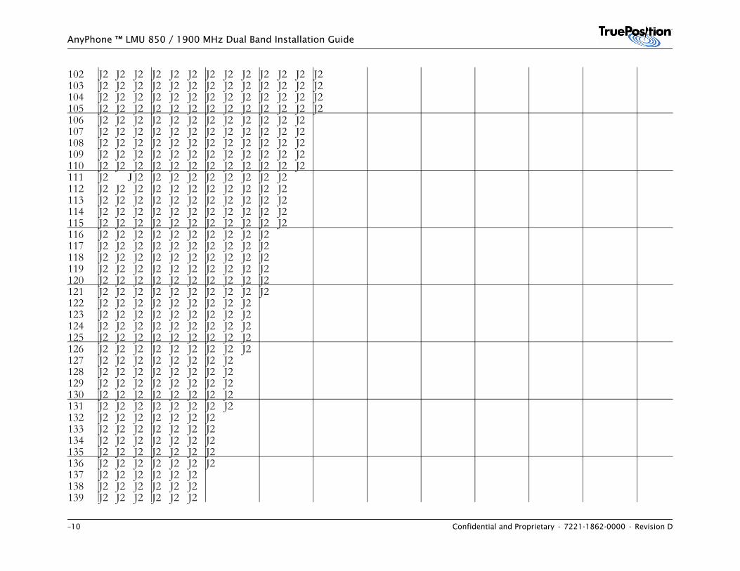
–10 Confidential and Proprietary • 7221-1862-0000 • Revision D
AnyPhone ™ LMU 850 / 1900 MHz Dual Band Installation Guide
102 J2 J2 J2 J2 J2 J2 J2 J2 J2 J2 J2 J2 J2103 J2 J2 J2 J2 J2 J2 J2 J2 J2 J2 J2 J2 J2104 J2 J2 J2 J2 J2 J2 J2 J2 J2 J2 J2 J2 J2105 J2 J2 J2 J2 J2 J2 J2 J2 J2 J2 J2 J2 J2106 J2 J2 J2 J2 J2 J2 J2 J2 J2 J2 J2 J2107 J2 J2 J2 J2 J2 J2 J2 J2 J2 J2 J2 J2108 J2 J2 J2 J2 J2 J2 J2 J2 J2 J2 J2 J2109 J2 J2 J2 J2 J2 J2 J2 J2 J2 J2 J2 J2110 J2 J2 J2 J2 J2 J2 J2 J2 J2 J2 J2 J2111 J2 J J2 J2 J2 J2 J2 J2 J2 J2 J2112 J2 J2 J2 J2 J2 J2 J2 J2 J2 J2 J2113 J2 J2 J2 J2 J2 J2 J2 J2 J2 J2 J2114 J2 J2 J2 J2 J2 J2 J2 J2 J2 J2 J2115 J2 J2 J2 J2 J2 J2 J2 J2 J2 J2 J2116 J2 J2 J2 J2 J2 J2 J2 J2 J2 J2117 J2 J2 J2 J2 J2 J2 J2 J2 J2 J2118 J2 J2 J2 J2 J2 J2 J2 J2 J2 J2119 J2 J2 J2 J2 J2 J2 J2 J2 J2 J2120 J2 J2 J2 J2 J2 J2 J2 J2 J2 J2121 J2 J2 J2 J2 J2 J2 J2 J2 J2 J2122 J2 J2 J2 J2 J2 J2 J2 J2 J2123 J2 J2 J2 J2 J2 J2 J2 J2 J2124 J2 J2 J2 J2 J2 J2 J2 J2 J2125 J2 J2 J2 J2 J2 J2 J2 J2 J2126 J2 J2 J2 J2 J2 J2 J2 J2 J2127 J2 J2 J2 J2 J2 J2 J2 J2128 J2 J2 J2 J2 J2 J2 J2 J2129 J2 J2 J2 J2 J2 J2 J2 J2130 J2 J2 J2 J2 J2 J2 J2 J2131 J2 J2 J2 J2 J2 J2 J2 J2132 J2 J2 J2 J2 J2 J2 J2133 J2 J2 J2 J2 J2 J2 J2134 J2 J2 J2 J2 J2 J2 J2135 J2 J2 J2 J2 J2 J2 J2136 J2 J2 J2 J2 J2 J2 J2137 J2 J2 J2 J2 J2 J2138 J2 J2 J2 J2 J2 J2139 J2 J2 J2 J2 J2 J2
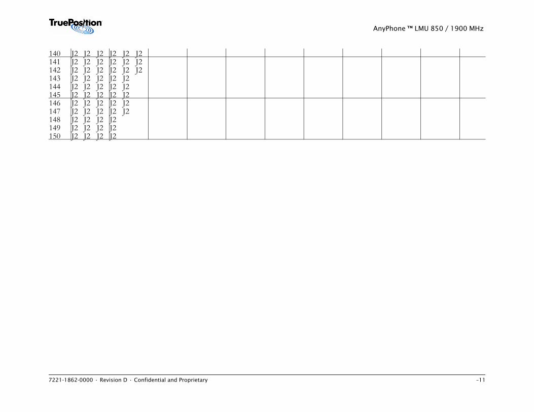
7221-1862-0000 • Revision D • Confidential and Proprietary –11
AnyPhone ™ LMU 850 / 1900 MHz
140 J2 J2 J2 J2 J2 J2141 J2 J2 J2 J2 J2 J2142 J2 J2 J2 J2 J2 J2143 J2 J2 J2 J2 J2144 J2 J2 J2 J2 J2145 J2 J2 J2 J2 J2146 J2 J2 J2 J2 J2147 J2 J2 J2 J2 J2148 J2 J2 J2 J2149 J2 J2 J2 J2150 J2 J2 J2 J2
7221-1862-0000 • Revision D • Confidential and Proprietary –12
AnyPhone ™ LMU 850 / 1900 MHz
AnyPhone™ LMU 850 MHz Installation Guide
7221-1861-0000 • Revision D • Confidential and Proprietary C-1
APPENDIX C. ANTENNA MOUNTS
ContentsC.1 Introduction . . . . . . . . . . . . . . . . . . . . . . . . . . . . . . . . . . . . . . . . . . . . . . . . . . . . . . . . . . C-1C.2 Ice Bridge or Ladder Bridge . . . . . . . . . . . . . . . . . . . . . . . . . . . . . . . . . . . . . . . . . . . . . . . C-2C.3 Wall Mounts . . . . . . . . . . . . . . . . . . . . . . . . . . . . . . . . . . . . . . . . . . . . . . . . . . . . . . . . . . . C-6C.4 Pole Mounts . . . . . . . . . . . . . . . . . . . . . . . . . . . . . . . . . . . . . . . . . . . . . . . . . . . . . . . . . C-10C.5 Tower Mount . . . . . . . . . . . . . . . . . . . . . . . . . . . . . . . . . . . . . . . . . . . . . . . . . . . . . . . . . C-16C.6 Install Kit KT-06-1748-00 . . . . . . . . . . . . . . . . . . . . . . . . . . . . . . . . . . . . . . . . . . . . . . . . C-20
C.1 IntroductionThis appendix defines the procedures for installing an external GPS and GSM downlink antenna using install kit KT-06-1745-00. This kit applies for ice bridge, ladder, wall, pole, and tower mounts.
For some installations KT-06-1749-00 applies. This kit may be used with KT-06-1745-00 or as a stand alone GSM downlink antenna installation.
Mounting a downlink antenna with an existing GPS use Kit 06-1748-00or in a standalone configuration use Kit 06-1754-00
For installations using other mounting kits and for complete instructions about antenna installations including cabling instructions, Fer to Section 7: Install GPS and External GSM Downlink Monitor Antennas.
A GPS antenna must always be installed in a location that provides an unobstructed view of the sky. To learn the specific requirements for determining an antenna location, refer to the Site Preparation Requirements document.
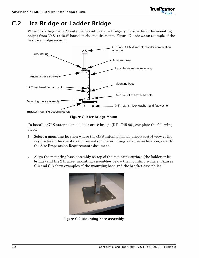
AnyPhone™ LMU 850 MHz Installation Guide
C-2 Confidential and Proprietary • 7221-1861-0000 • Revision D
C.2 Ice Bridge or Ladder BridgeWhen installing the GPS antenna mount to an ice bridge, you can extend the mounting height from 20.8" to 40.8" based on site requirements. Figure C-1 shows an example of the basic ice bridge mount.
Figure C-1: Ice Bridge Mount
To install a GPS antenna on a ladder or ice bridge (KT-1745-00), complete the following steps:
1 Select a mounting location where the GPS antenna has an unobstructed view of the sky. To learn the specific requirements for determining an antenna location, refer to the Site Preparation Requirements document.
2 Align the mounting base assembly on top of the mounting surface (the ladder or ice bridge) and the 2 bracket mounting assemblies below the mounting surface. Figures C-2 and C-3 show examples of the mounting base and the bracket assemblies.
Figure C-2: Mounting base assembly
3/8” hex nut, lock washer, and flat washer
3/8” by 3” LG hex head bolt
Mounting base
Mounting base assembly
Bracket mounting assemblies (2)
Top antenna mount assembly
Antenna base screws
Ground lug
Antenna base
1.75" hex head bolt and nut
GPS and GSM downlink monitor combinationantenna
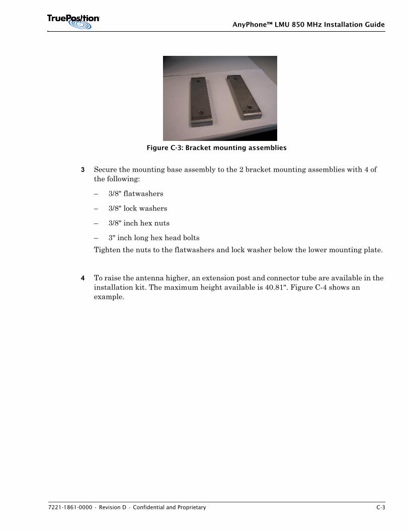
AnyPhone™ LMU 850 MHz Installation Guide
7221-1861-0000 • Revision D • Confidential and Proprietary C-3
Figure C-3: Bracket mounting assemblies
3 Secure the mounting base assembly to the 2 bracket mounting assemblies with 4 of the following:
– 3/8" flatwashers
– 3/8" lock washers
– 3/8" inch hex nuts
– 3" inch long hex head bolts Tighten the nuts to the flatwashers and lock washer below the lower mounting plate.
4 To raise the antenna higher, an extension post and connector tube are available in the installation kit. The maximum height available is 40.81". Figure C-4 shows an example.
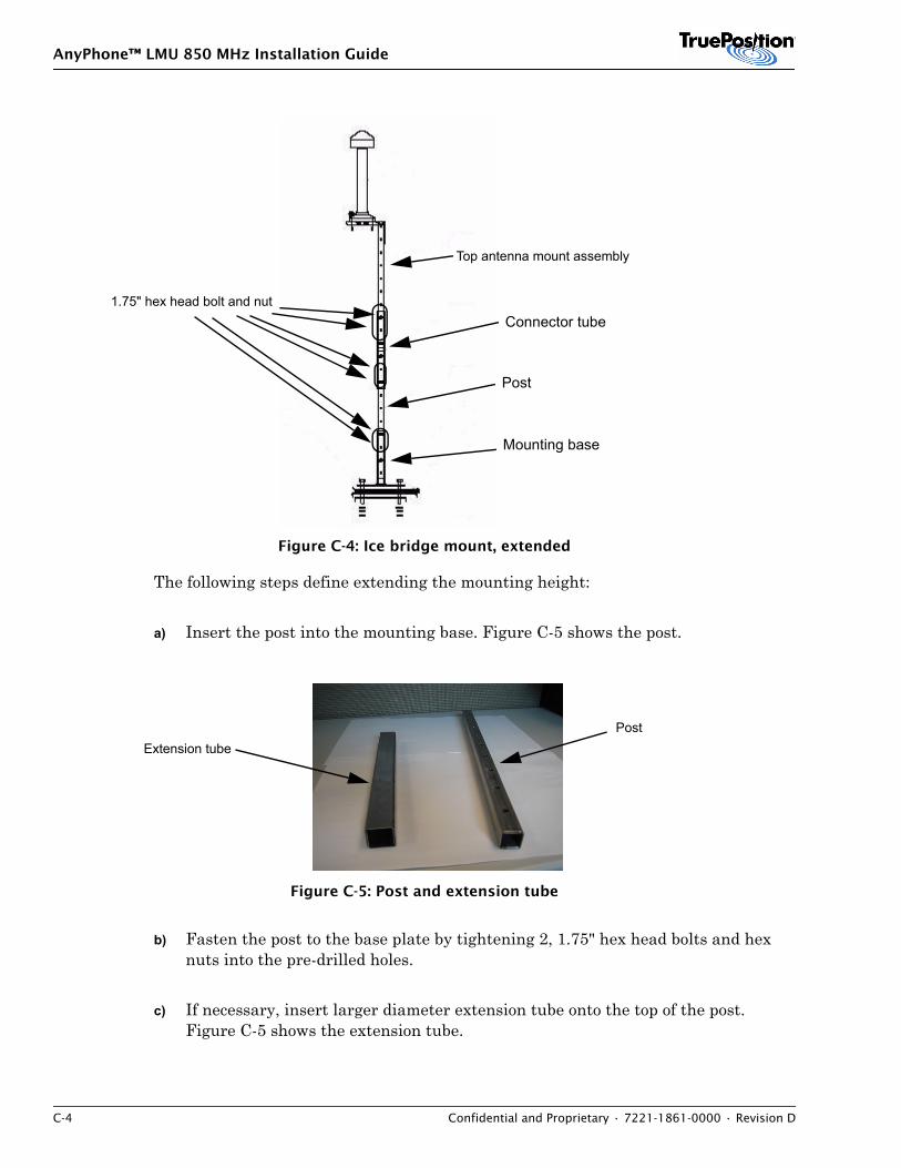
AnyPhone™ LMU 850 MHz Installation Guide
C-4 Confidential and Proprietary • 7221-1861-0000 • Revision D
Figure C-4: Ice bridge mount, extended
The following steps define extending the mounting height:
a) Insert the post into the mounting base. Figure C-5 shows the post.
Figure C-5: Post and extension tube
b) Fasten the post to the base plate by tightening 2, 1.75" hex head bolts and hex nuts into the pre-drilled holes.
c) If necessary, insert larger diameter extension tube onto the top of the post. Figure C-5 shows the extension tube.
Post
Mounting base
Connector tube
Top antenna mount assembly
1.75" hex head bolt and nut
PostExtension tube
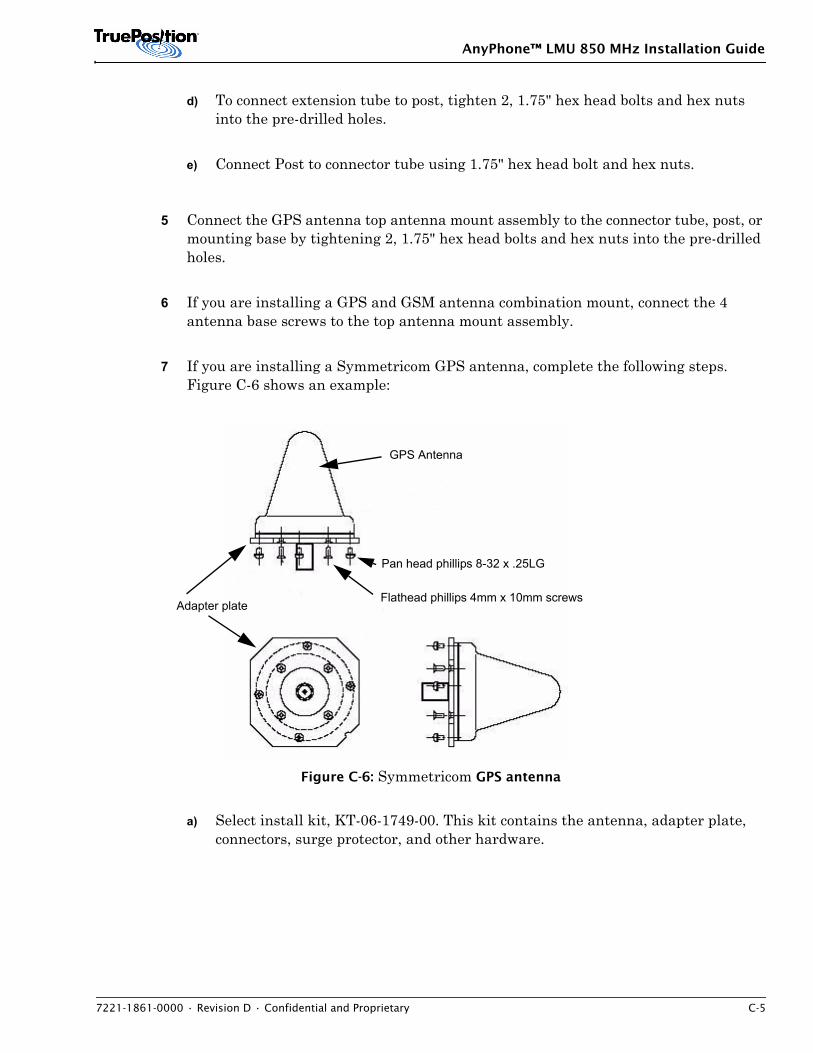
AnyPhone™ LMU 850 MHz Installation Guide
7221-1861-0000 • Revision D • Confidential and Proprietary C-5
d) To connect extension tube to post, tighten 2, 1.75" hex head bolts and hex nuts into the pre-drilled holes.
e) Connect Post to connector tube using 1.75" hex head bolt and hex nuts.
5 Connect the GPS antenna top antenna mount assembly to the connector tube, post, or mounting base by tightening 2, 1.75" hex head bolts and hex nuts into the pre-drilled holes.
6 If you are installing a GPS and GSM antenna combination mount, connect the 4 antenna base screws to the top antenna mount assembly.
7 If you are installing a Symmetricom GPS antenna, complete the following steps. Figure C-6 shows an example:
Figure C-6: Symmetricom GPS antenna
a) Select install kit, KT-06-1749-00. This kit contains the antenna, adapter plate, connectors, surge protector, and other hardware.
GPS Antenna
Pan head phillips 8-32 x .25LG
Flathead phillips 4mm x 10mm screws Adapter plate
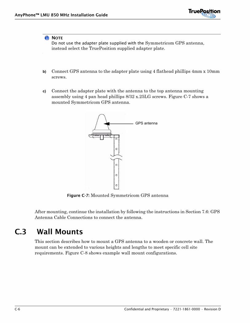
AnyPhone™ LMU 850 MHz Installation Guide
C-6 Confidential and Proprietary • 7221-1861-0000 • Revision D
NOTE
Do not use the adapter plate supplied with the Symmetricom GPS antenna, instead select the TruePosition supplied adapter plate.
b) Connect GPS antenna to the adapter plate using 4 flathead phillips 4mm x 10mm screws.
c) Connect the adapter plate with the antenna to the top antenna mounting assembly using 4 pan head phillips 8/32 x.25LG screws. Figure C-7 shows a mounted Symmetricom GPS antenna.
Figure C-7: Mounted Symmetricom GPS antenna
After mounting, continue the installation by following the instructions in Section 7.6: GPS Antenna Cable Connections to connect the antenna.
C.3 Wall MountsThis section describes how to mount a GPS antenna to a wooden or concrete wall. The mount can be extended to various heights and lengths to meet specific cell site requirements. Figure C-8 shows example wall mount configurations.
GPS antenna
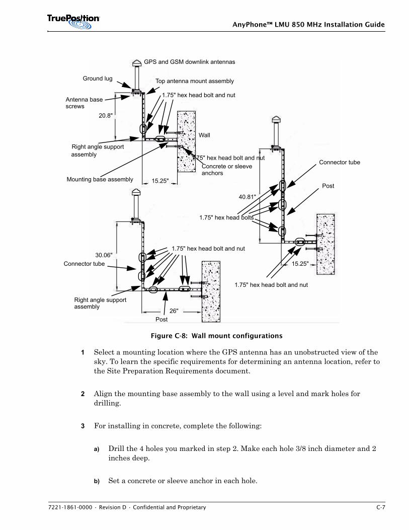
AnyPhone™ LMU 850 MHz Installation Guide
7221-1861-0000 • Revision D • Confidential and Proprietary C-7
Figure C-8: Wall mount configurations
1 Select a mounting location where the GPS antenna has an unobstructed view of the sky. To learn the specific requirements for determining an antenna location, refer to the Site Preparation Requirements document.
2 Align the mounting base assembly to the wall using a level and mark holes for drilling.
3 For installing in concrete, complete the following:
a) Drill the 4 holes you marked in step 2. Make each hole 3/8 inch diameter and 2 inches deep.
b) Set a concrete or sleeve anchor in each hole.
20.8"
15.25"
30.06"
26"
40.81"
15.25"
GPS and GSM downlink antennas
Mounting base assembly
Right angle supportassembly
Top antenna mount assembly
Wall
Concrete or sleeveanchors
Post
Connector tube
Ground lug
Right angle supportassembly
Post
Connector tube
Antenna basescrews
1.75" hex head bolts
1.75" hex head bolt and nut
1.75" hex head bolt and nut
1.75" hex head bolt and nut
1.75" hex head bolt and nut
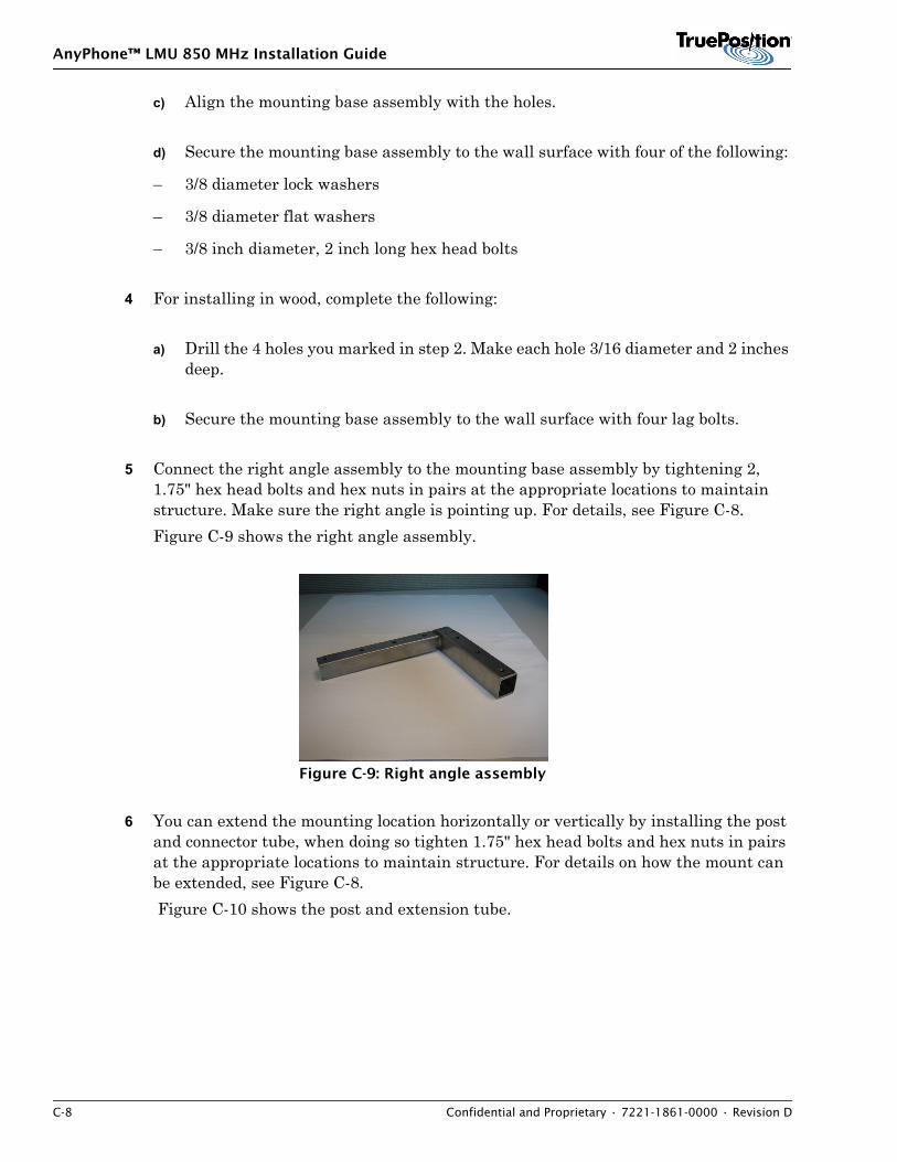
AnyPhone™ LMU 850 MHz Installation Guide
C-8 Confidential and Proprietary • 7221-1861-0000 • Revision D
c) Align the mounting base assembly with the holes.
d) Secure the mounting base assembly to the wall surface with four of the following:
– 3/8 diameter lock washers
– 3/8 diameter flat washers
– 3/8 inch diameter, 2 inch long hex head bolts
4 For installing in wood, complete the following:
a) Drill the 4 holes you marked in step 2. Make each hole 3/16 diameter and 2 inches deep.
b) Secure the mounting base assembly to the wall surface with four lag bolts.
5 Connect the right angle assembly to the mounting base assembly by tightening 2, 1.75" hex head bolts and hex nuts in pairs at the appropriate locations to maintain structure. Make sure the right angle is pointing up. For details, see Figure C-8. Figure C-9 shows the right angle assembly.
Figure C-9: Right angle assembly
6 You can extend the mounting location horizontally or vertically by installing the post and connector tube, when doing so tighten 1.75" hex head bolts and hex nuts in pairs at the appropriate locations to maintain structure. For details on how the mount can be extended, see Figure C-8. Figure C-10 shows the post and extension tube.
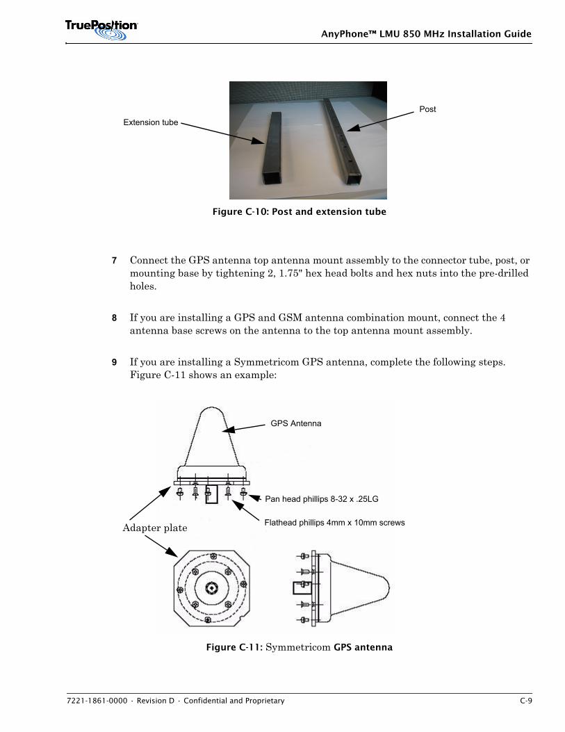
AnyPhone™ LMU 850 MHz Installation Guide
7221-1861-0000 • Revision D • Confidential and Proprietary C-9
Figure C-10: Post and extension tube
7 Connect the GPS antenna top antenna mount assembly to the connector tube, post, or mounting base by tightening 2, 1.75" hex head bolts and hex nuts into the pre-drilled holes.
8 If you are installing a GPS and GSM antenna combination mount, connect the 4 antenna base screws on the antenna to the top antenna mount assembly.
9 If you are installing a Symmetricom GPS antenna, complete the following steps. Figure C-11 shows an example:
Figure C-11: Symmetricom GPS antenna
PostExtension tube
GPS Antenna
Pan head phillips 8-32 x .25LG
Flathead phillips 4mm x 10mm screws Adapter plate
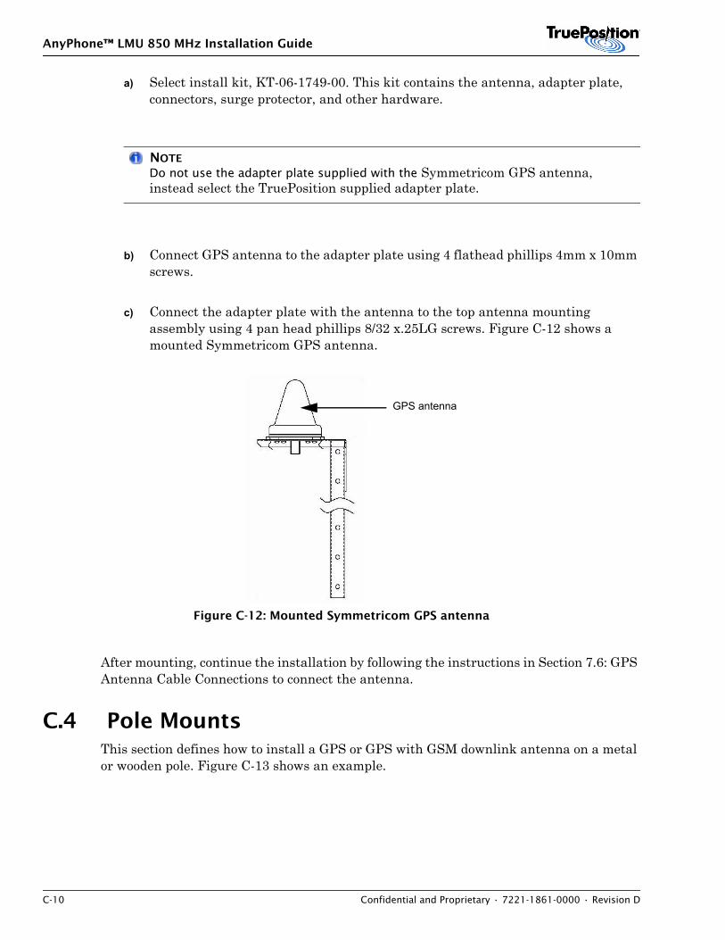
AnyPhone™ LMU 850 MHz Installation Guide
C-10 Confidential and Proprietary • 7221-1861-0000 • Revision D
a) Select install kit, KT-06-1749-00. This kit contains the antenna, adapter plate, connectors, surge protector, and other hardware.
NOTE
Do not use the adapter plate supplied with the Symmetricom GPS antenna, instead select the TruePosition supplied adapter plate.
b) Connect GPS antenna to the adapter plate using 4 flathead phillips 4mm x 10mm screws.
c) Connect the adapter plate with the antenna to the top antenna mounting assembly using 4 pan head phillips 8/32 x.25LG screws. Figure C-12 shows a mounted Symmetricom GPS antenna.
Figure C-12: Mounted Symmetricom GPS antenna
After mounting, continue the installation by following the instructions in Section 7.6: GPS Antenna Cable Connections to connect the antenna.
C.4 Pole MountsThis section defines how to install a GPS or GPS with GSM downlink antenna on a metal or wooden pole. Figure C-13 shows an example.
GPS antenna
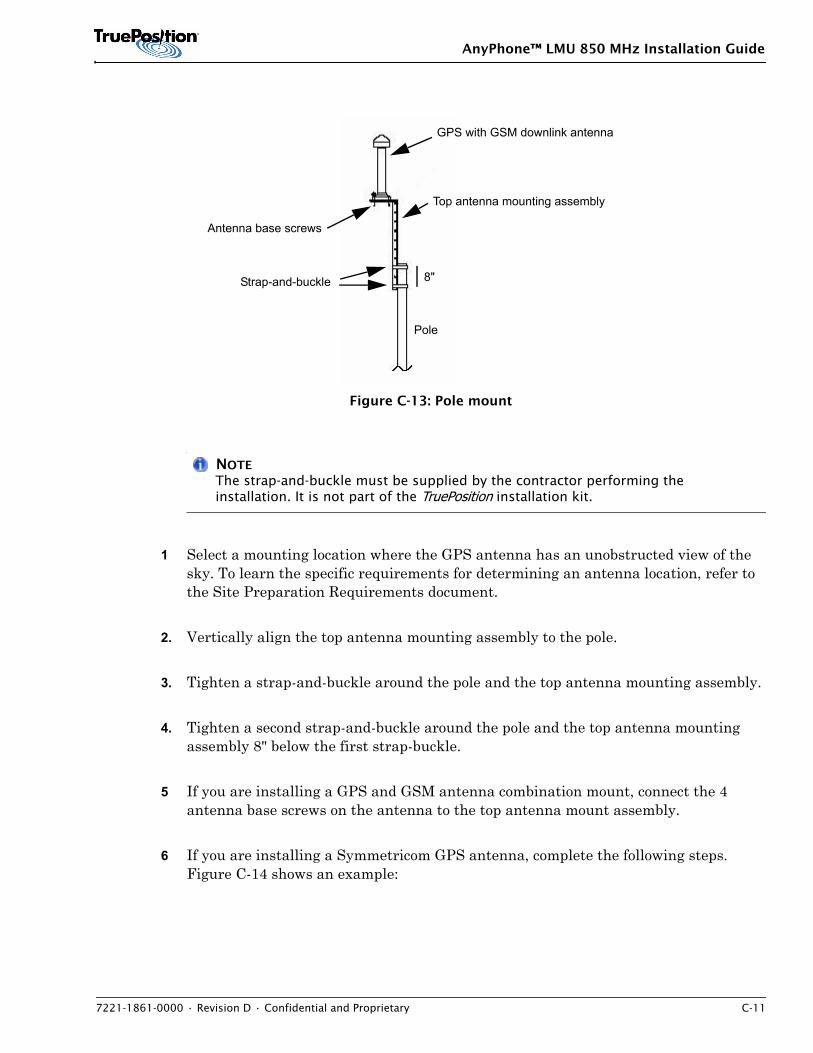
AnyPhone™ LMU 850 MHz Installation Guide
7221-1861-0000 • Revision D • Confidential and Proprietary C-11
Figure C-13: Pole mount
NOTEThe strap-and-buckle must be supplied by the contractor performing the installation. It is not part of the TruePosition installation kit.
1 Select a mounting location where the GPS antenna has an unobstructed view of the sky. To learn the specific requirements for determining an antenna location, refer to the Site Preparation Requirements document.
2. Vertically align the top antenna mounting assembly to the pole.
3. Tighten a strap-and-buckle around the pole and the top antenna mounting assembly.
4. Tighten a second strap-and-buckle around the pole and the top antenna mounting assembly 8" below the first strap-buckle.
5 If you are installing a GPS and GSM antenna combination mount, connect the 4 antenna base screws on the antenna to the top antenna mount assembly.
6 If you are installing a Symmetricom GPS antenna, complete the following steps. Figure C-14 shows an example:
Top antenna mounting assembly
GPS with GSM downlink antenna
Pole
Antenna base screws
8"Strap-and-buckle
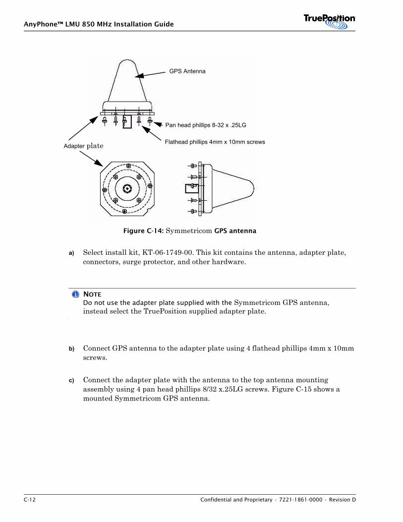
AnyPhone™ LMU 850 MHz Installation Guide
C-12 Confidential and Proprietary • 7221-1861-0000 • Revision D
Figure C-14: Symmetricom GPS antenna
a) Select install kit, KT-06-1749-00. This kit contains the antenna, adapter plate, connectors, surge protector, and other hardware.
NOTE
Do not use the adapter plate supplied with the Symmetricom GPS antenna, instead select the TruePosition supplied adapter plate.
b) Connect GPS antenna to the adapter plate using 4 flathead phillips 4mm x 10mm screws.
c) Connect the adapter plate with the antenna to the top antenna mounting assembly using 4 pan head phillips 8/32 x.25LG screws. Figure C-15 shows a mounted Symmetricom GPS antenna.
GPS Antenna
Pan head phillips 8-32 x .25LG
Flathead phillips 4mm x 10mm screws Adapter plate
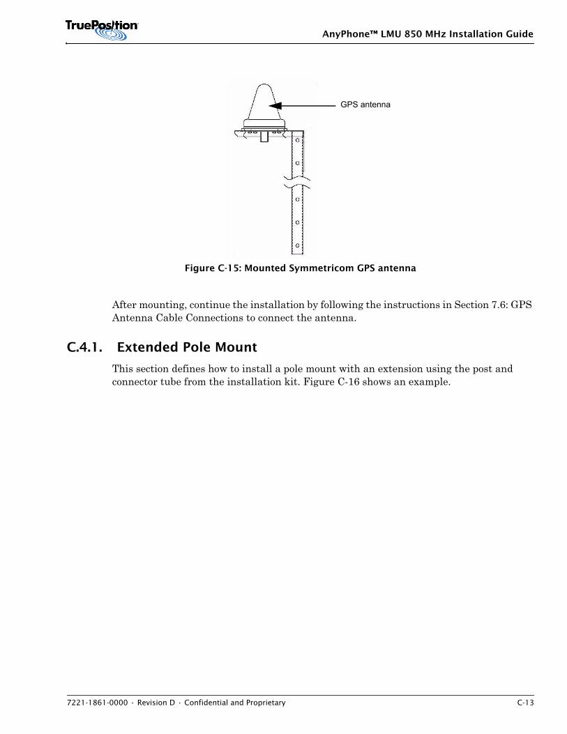
AnyPhone™ LMU 850 MHz Installation Guide
7221-1861-0000 • Revision D • Confidential and Proprietary C-13
Figure C-15: Mounted Symmetricom GPS antenna
After mounting, continue the installation by following the instructions in Section 7.6: GPS Antenna Cable Connections to connect the antenna.
C.4.1. Extended Pole Mount
This section defines how to install a pole mount with an extension using the post and connector tube from the installation kit. Figure C-16 shows an example.
GPS antenna
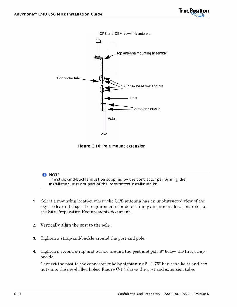
AnyPhone™ LMU 850 MHz Installation Guide
C-14 Confidential and Proprietary • 7221-1861-0000 • Revision D
Figure C-16: Pole mount extension
NOTEThe strap-and-buckle must be supplied by the contractor performing the installation. It is not part of the TruePosition installation kit.
1 Select a mounting location where the GPS antenna has an unobstructed view of the sky. To learn the specific requirements for determining an antenna location, refer to the Site Preparation Requirements document.
2. Vertically align the post to the pole.
3. Tighten a strap-and-buckle around the post and pole.
4. Tighten a second strap-and-buckle around the post and pole 8" below the first strap-buckle.Connect the post to the connector tube by tightening 2, 1.75" hex head bolts and hex nuts into the pre-drilled holes. Figure C-17 shows the post and extension tube.
1.75" hex head bolt and nut
Post
Connector tube
Top antenna mounting assembly
Pole
GPS and GSM downlink antenna
Strap and buckle

AnyPhone™ LMU 850 MHz Installation Guide
7221-1861-0000 • Revision D • Confidential and Proprietary C-15
Figure C-17: Post and extension tube
5 Connect the GPS antenna top antenna mount assembly to the connector tube by tightening 2, 1.75" hex head bolts and hex nuts into the pre-drilled holes.
6 If you are installing a GPS and GSM antenna combination mount, connect the 4 antenna base screws on the antenna to the top antenna mount assembly.
7 If you are installing a Symmetricom GPS antenna, complete the following steps. Figure C-18 shows an example:
Figure C-18: Symmetricom GPS antenna
a) Select install kit, KT-06-1749-00. This kit contains the antenna, adapter plate, connectors, surge protector, and other hardware.
PostExtension tube
GPS Antenna
Pan head phillips 8-32 x .25LG
Flathead phillips 4mm x 10mm screws Adapter plate
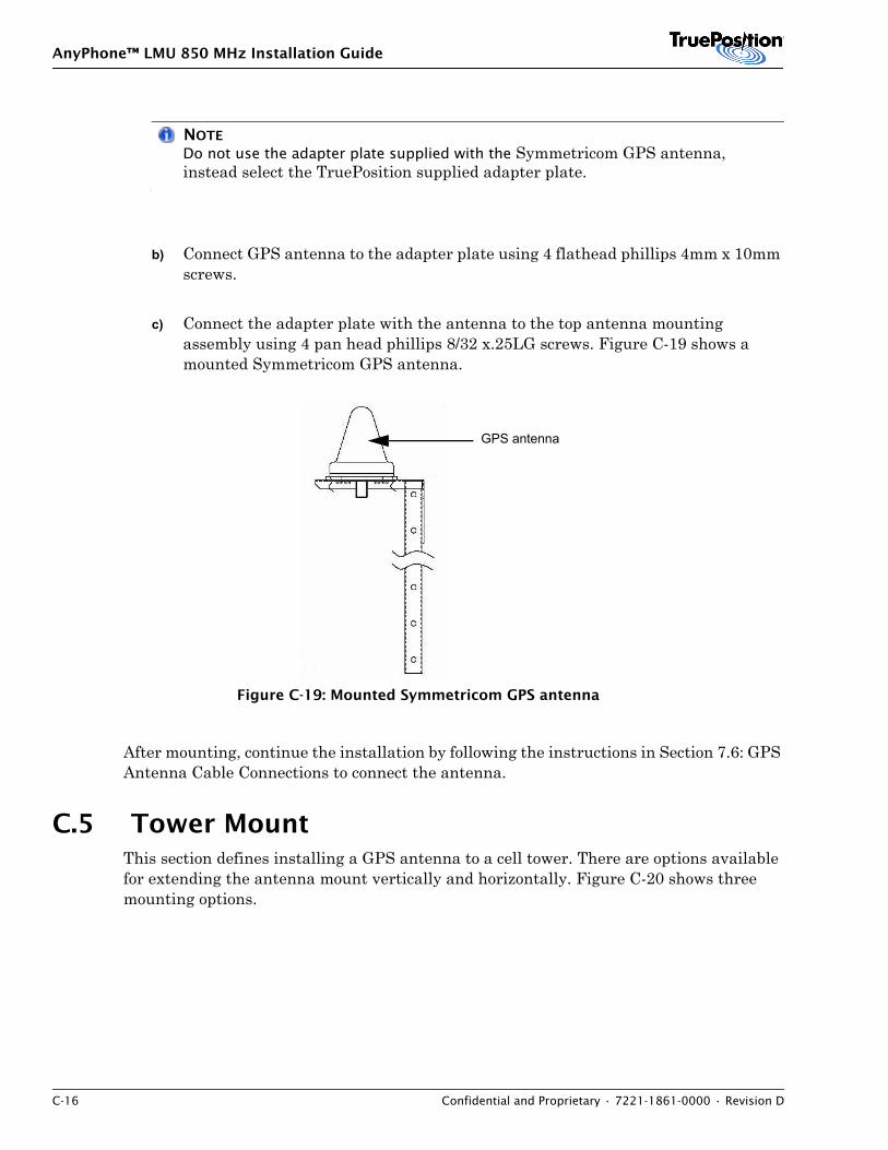
AnyPhone™ LMU 850 MHz Installation Guide
C-16 Confidential and Proprietary • 7221-1861-0000 • Revision D
NOTE
Do not use the adapter plate supplied with the Symmetricom GPS antenna, instead select the TruePosition supplied adapter plate.
b) Connect GPS antenna to the adapter plate using 4 flathead phillips 4mm x 10mm screws.
c) Connect the adapter plate with the antenna to the top antenna mounting assembly using 4 pan head phillips 8/32 x.25LG screws. Figure C-19 shows a mounted Symmetricom GPS antenna.
Figure C-19: Mounted Symmetricom GPS antenna
After mounting, continue the installation by following the instructions in Section 7.6: GPS Antenna Cable Connections to connect the antenna.
C.5 Tower MountThis section defines installing a GPS antenna to a cell tower. There are options available for extending the antenna mount vertically and horizontally. Figure C-20 shows three mounting options.
GPS antenna
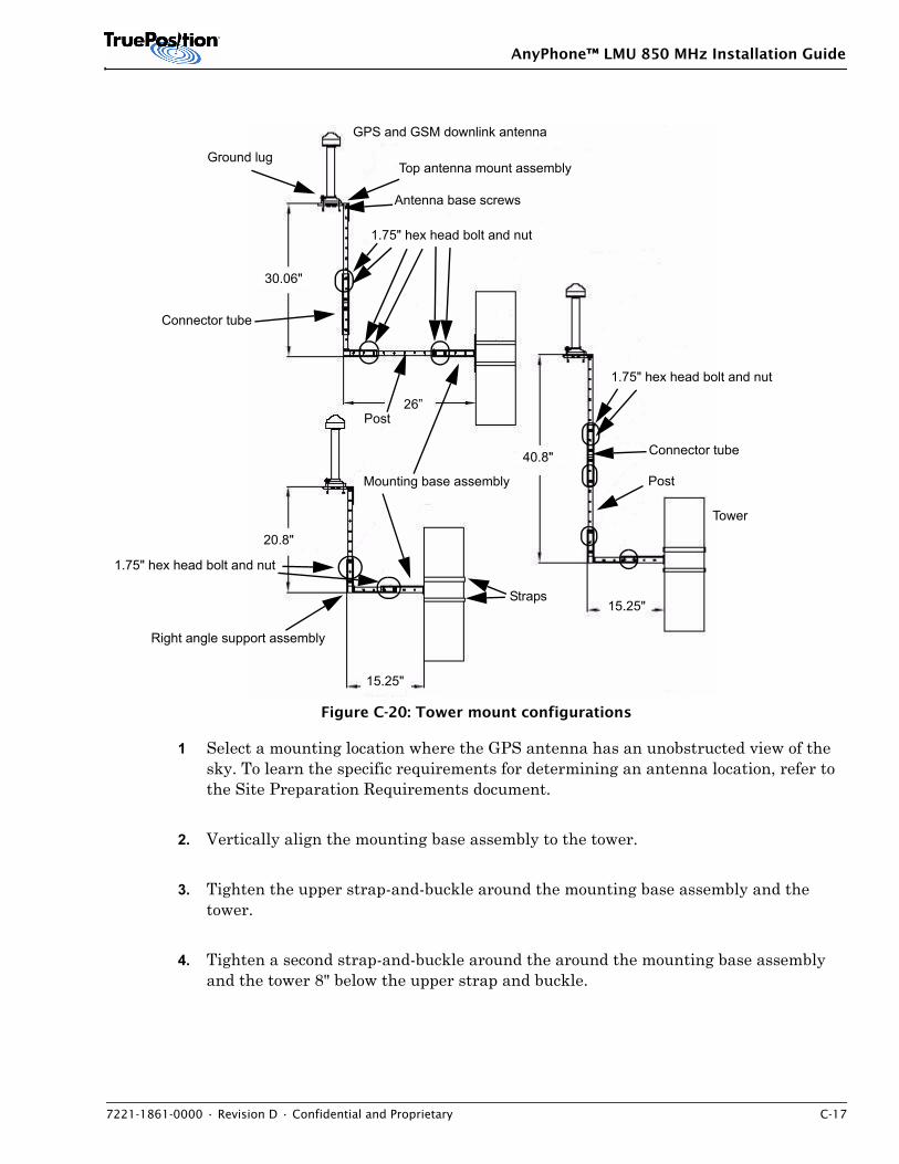
AnyPhone™ LMU 850 MHz Installation Guide
7221-1861-0000 • Revision D • Confidential and Proprietary C-17
Figure C-20: Tower mount configurations
1 Select a mounting location where the GPS antenna has an unobstructed view of the sky. To learn the specific requirements for determining an antenna location, refer to the Site Preparation Requirements document.
2. Vertically align the mounting base assembly to the tower.
3. Tighten the upper strap-and-buckle around the mounting base assembly and the tower.
4. Tighten a second strap-and-buckle around the around the mounting base assembly and the tower 8" below the upper strap and buckle.
30.06"
26”
40.8"
15.25"
15.25"
20.8"
GPS and GSM downlink antenna
Ground lug
Antenna base screws
Right angle support assembly
Mounting base assembly
1.75" hex head bolt and nut
Straps
Top antenna mount assembly
1.75" hex head bolt and nut
Post
Connector tube
Post
Connector tube
1.75" hex head bolt and nut
Tower
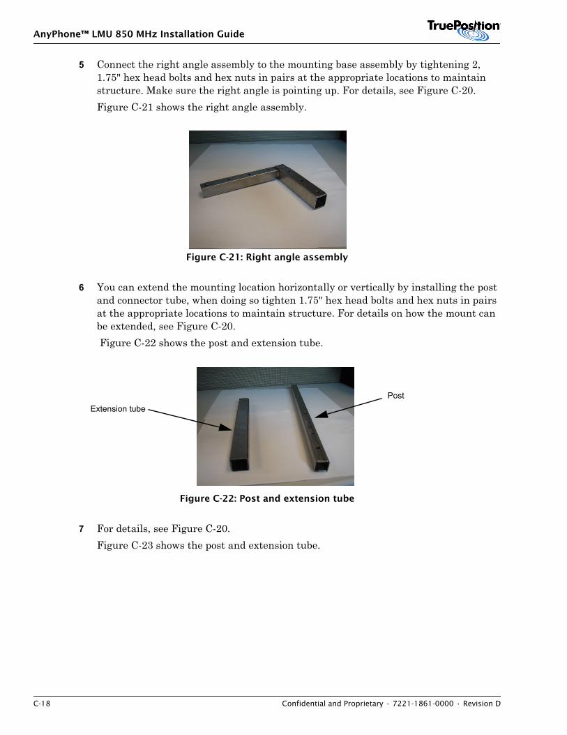
AnyPhone™ LMU 850 MHz Installation Guide
C-18 Confidential and Proprietary • 7221-1861-0000 • Revision D
5 Connect the right angle assembly to the mounting base assembly by tightening 2, 1.75" hex head bolts and hex nuts in pairs at the appropriate locations to maintain structure. Make sure the right angle is pointing up. For details, see Figure C-20. Figure C-21 shows the right angle assembly.
Figure C-21: Right angle assembly
6 You can extend the mounting location horizontally or vertically by installing the post and connector tube, when doing so tighten 1.75" hex head bolts and hex nuts in pairs at the appropriate locations to maintain structure. For details on how the mount can be extended, see Figure C-20. Figure C-22 shows the post and extension tube.
Figure C-22: Post and extension tube
7 For details, see Figure C-20.Figure C-23 shows the post and extension tube.
PostExtension tube
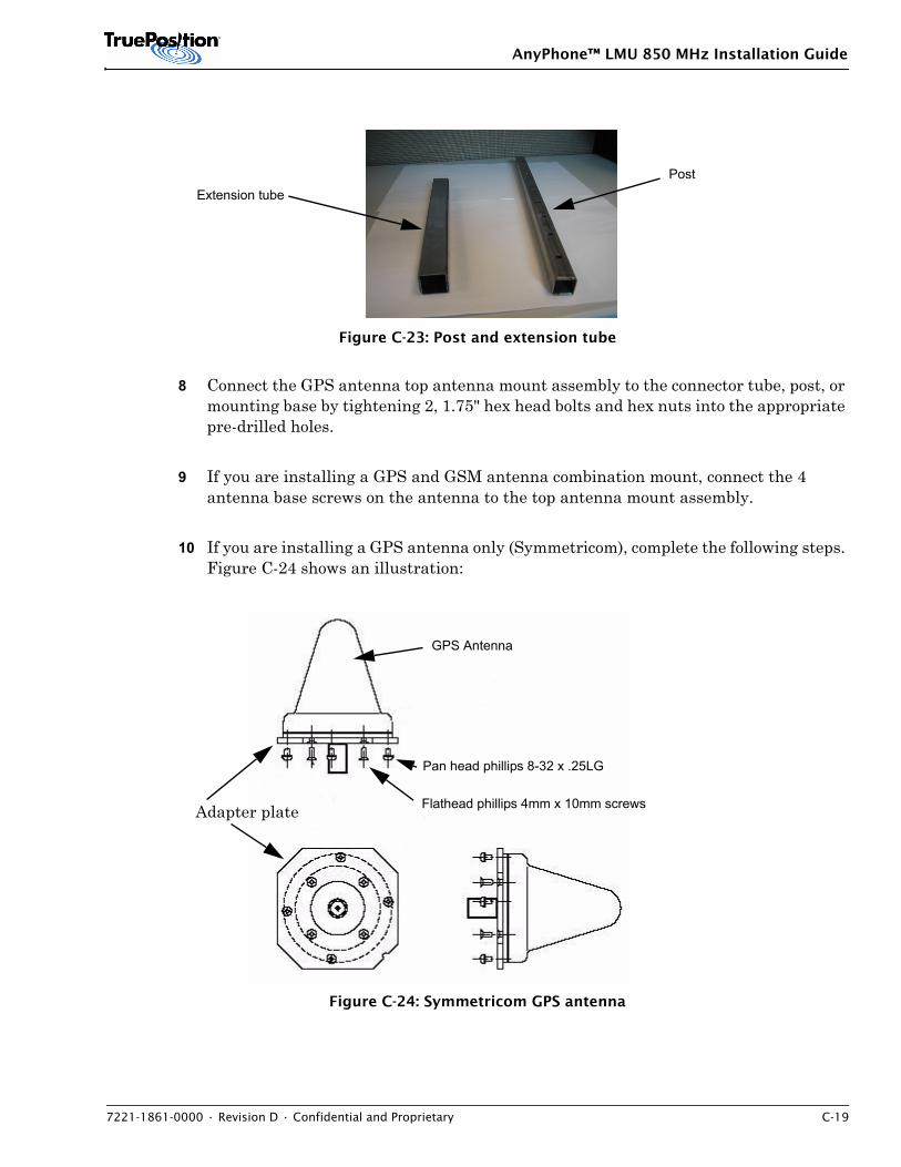
AnyPhone™ LMU 850 MHz Installation Guide
7221-1861-0000 • Revision D • Confidential and Proprietary C-19
Figure C-23: Post and extension tube
8 Connect the GPS antenna top antenna mount assembly to the connector tube, post, or mounting base by tightening 2, 1.75" hex head bolts and hex nuts into the appropriate pre-drilled holes.
9 If you are installing a GPS and GSM antenna combination mount, connect the 4 antenna base screws on the antenna to the top antenna mount assembly.
10 If you are installing a GPS antenna only (Symmetricom), complete the following steps. Figure C-24 shows an illustration:
Figure C-24: Symmetricom GPS antenna
PostExtension tube
GPS Antenna
Pan head phillips 8-32 x .25LG
Flathead phillips 4mm x 10mm screws Adapter plate
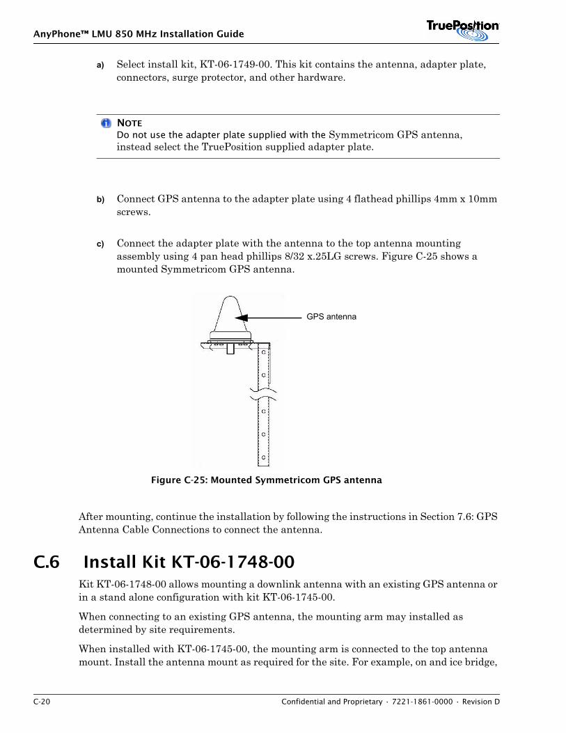
AnyPhone™ LMU 850 MHz Installation Guide
C-20 Confidential and Proprietary • 7221-1861-0000 • Revision D
a) Select install kit, KT-06-1749-00. This kit contains the antenna, adapter plate, connectors, surge protector, and other hardware.
NOTE
Do not use the adapter plate supplied with the Symmetricom GPS antenna, instead select the TruePosition supplied adapter plate.
b) Connect GPS antenna to the adapter plate using 4 flathead phillips 4mm x 10mm screws.
c) Connect the adapter plate with the antenna to the top antenna mounting assembly using 4 pan head phillips 8/32 x.25LG screws. Figure C-25 shows a mounted Symmetricom GPS antenna.
Figure C-25: Mounted Symmetricom GPS antenna
After mounting, continue the installation by following the instructions in Section 7.6: GPS Antenna Cable Connections to connect the antenna.
C.6 Install Kit KT-06-1748-00Kit KT-06-1748-00 allows mounting a downlink antenna with an existing GPS antenna or in a stand alone configuration with kit KT-06-1745-00.
When connecting to an existing GPS antenna, the mounting arm may installed as determined by site requirements.
When installed with KT-06-1745-00, the mounting arm is connected to the top antenna mount. Install the antenna mount as required for the site. For example, on and ice bridge,
GPS antenna
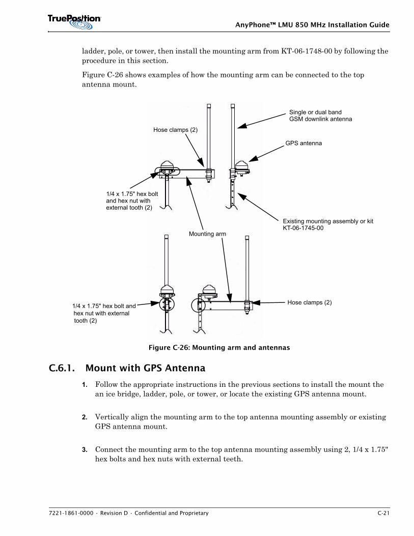
AnyPhone™ LMU 850 MHz Installation Guide
7221-1861-0000 • Revision D • Confidential and Proprietary C-21
ladder, pole, or tower, then install the mounting arm from KT-06-1748-00 by following the procedure in this section.
Figure C-26 shows examples of how the mounting arm can be connected to the top antenna mount.
Figure C-26: Mounting arm and antennas
C.6.1. Mount with GPS Antenna
1. Follow the appropriate instructions in the previous sections to install the mount the an ice bridge, ladder, pole, or tower, or locate the existing GPS antenna mount.
2. Vertically align the mounting arm to the top antenna mounting assembly or existing GPS antenna mount.
3. Connect the mounting arm to the top antenna mounting assembly using 2, 1/4 x 1.75" hex bolts and hex nuts with external teeth.
Single or dual band GSM downlink antenna
GPS antenna
1/4 x 1.75" hex boltand hex nut withexternal tooth (2)
Existing mounting assembly or kitKT-06-1745-00
1/4 x 1.75" hex bolt andhex nut with externaltooth (2)
Mounting arm
Hose clamps (2)
Hose clamps (2)
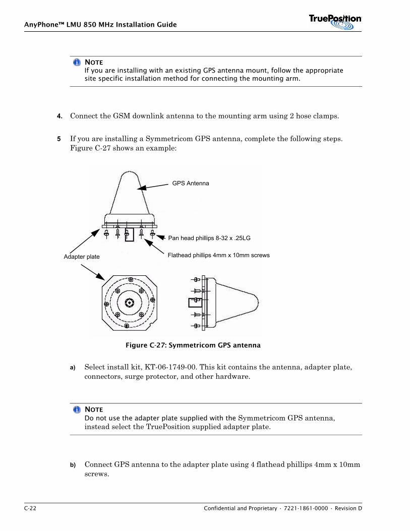
AnyPhone™ LMU 850 MHz Installation Guide
C-22 Confidential and Proprietary • 7221-1861-0000 • Revision D
NOTEIf you are installing with an existing GPS antenna mount, follow the appropriate site specific installation method for connecting the mounting arm.
4. Connect the GSM downlink antenna to the mounting arm using 2 hose clamps.
5 If you are installing a Symmetricom GPS antenna, complete the following steps. Figure C-27 shows an example:
Figure C-27: Symmetricom GPS antenna
a) Select install kit, KT-06-1749-00. This kit contains the antenna, adapter plate, connectors, surge protector, and other hardware.
NOTE
Do not use the adapter plate supplied with the Symmetricom GPS antenna, instead select the TruePosition supplied adapter plate.
b) Connect GPS antenna to the adapter plate using 4 flathead phillips 4mm x 10mm screws.
GPS Antenna
Pan head phillips 8-32 x .25LG
Flathead phillips 4mm x 10mm screws Adapter plate
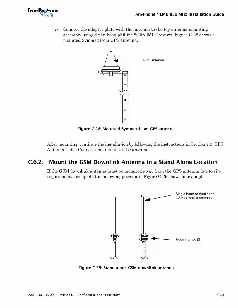
AnyPhone™ LMU 850 MHz Installation Guide
7221-1861-0000 • Revision D • Confidential and Proprietary C-23
c) Connect the adapter plate with the antenna to the top antenna mounting assembly using 4 pan head phillips 8/32 x.25LG screws. Figure C-28 shows a mounted Symmetricom GPS antenna.
Figure C-28: Mounted Symmetricom GPS antenna
After mounting, continue the installation by following the instructions in Section 7.6: GPS Antenna Cable Connections to connect the antenna.
C.6.2. Mount the GSM Downlink Antenna in a Stand Alone Location
If the GSM downlink antenna must be mounted away from the GPS antenna due to site requirements, complete the following procedure. Figure C-29 shows an example.
Figure C-29: Stand alone GSM downlink antenna
GPS antenna
Single band or dual bandGSM downlink antenna
Hose clamps (2)
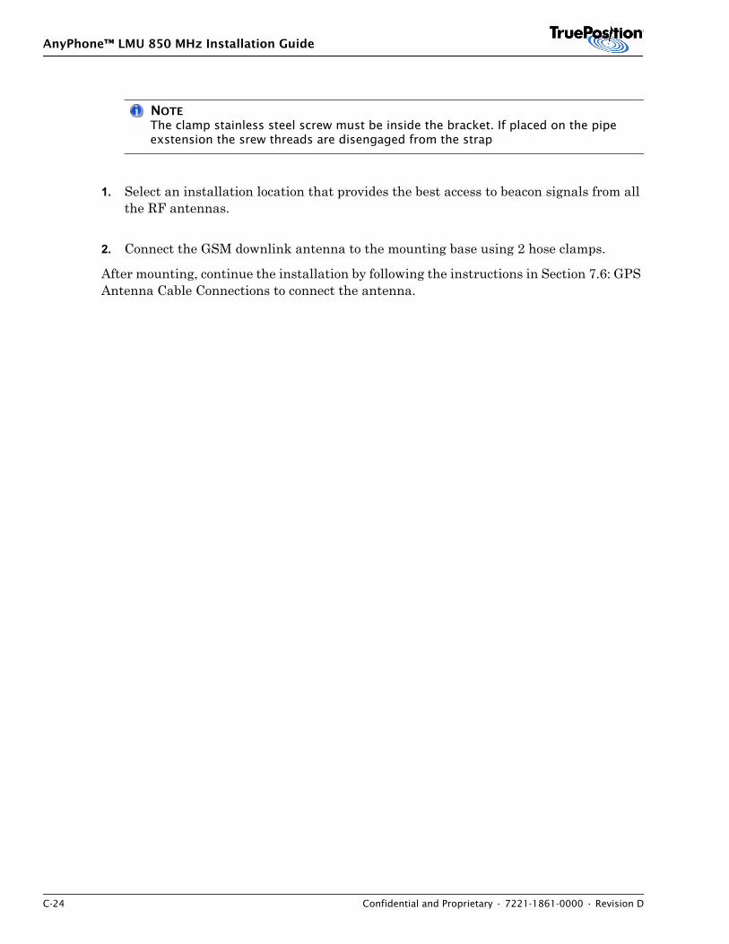
AnyPhone™ LMU 850 MHz Installation Guide
C-24 Confidential and Proprietary • 7221-1861-0000 • Revision D
NOTEThe clamp stainless steel screw must be inside the bracket. If placed on the pipe exstension the srew threads are disengaged from the strap
1. Select an installation location that provides the best access to beacon signals from all the RF antennas.
2. Connect the GSM downlink antenna to the mounting base using 2 hose clamps.
After mounting, continue the installation by following the instructions in Section 7.6: GPS Antenna Cable Connections to connect the antenna.
AnyPhone™ LMU 850 MHz Installation Guide
7221-1861-0000 • Revision D • Confidential and Proprietary D-1
APPENDIX D. LMU QUICK REFERENCE TROUBLESHOOTING
D.1 IntroductionThis document lists the failures that occur most often during LMU operation and the procedure to correct each problem.
NOTEThis troubleshooting document assumes the technician is familiar with the GPS Antenna Basic Rule Set.
D.2 Top Failures
NOTEUse the last seven days alarms as a basis for troubleshooting
The following is a list of the most common failures with the LMU or its installation:
• LMU Node Unreachable Alarm
• GPS Antenna Failure Alarm
• GPS Holdover Alarm
• GPS Timing Anomaly Alarm
D.3 Problem Detection and Correction
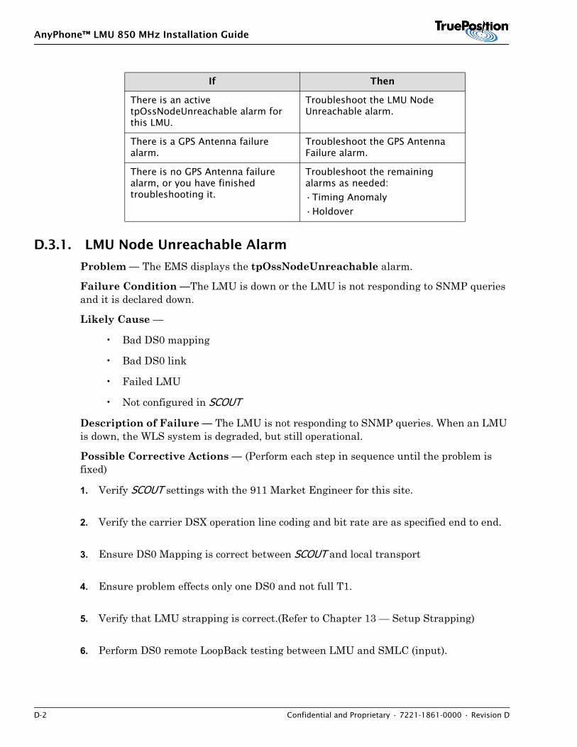
AnyPhone™ LMU 850 MHz Installation Guide
D-2 Confidential and Proprietary • 7221-1861-0000 • Revision D
D.3.1. LMU Node Unreachable Alarm
Problem — The EMS displays the tpOssNodeUnreachable alarm.
Failure Condition —The LMU is down or the LMU is not responding to SNMP queries and it is declared down.
Likely Cause —
• Bad DS0 mapping
• Bad DS0 link
• Failed LMU
• Not configured in SCOUT
Description of Failure — The LMU is not responding to SNMP queries. When an LMU is down, the WLS system is degraded, but still operational.
Possible Corrective Actions — (Perform each step in sequence until the problem is fixed)
1. Verify SCOUT settings with the 911 Market Engineer for this site.
2. Verify the carrier DSX operation line coding and bit rate are as specified end to end.
3. Ensure DS0 Mapping is correct between SCOUT and local transport
4. Ensure problem effects only one DS0 and not full T1.
5. Verify that LMU strapping is correct.(Refer to Chapter 13 — Setup Strapping)
6. Perform DS0 remote LoopBack testing between LMU and SMLC (input).
If Then
There is an active tpOssNodeUnreachable alarm for this LMU.
Troubleshoot the LMU Node Unreachable alarm.
There is a GPS Antenna failure alarm.
Troubleshoot the GPS Antenna Failure alarm.
There is no GPS Antenna failure alarm, or you have finished troubleshooting it.
Troubleshoot the remaining alarms as needed:
•Timing Anomaly
•Holdover
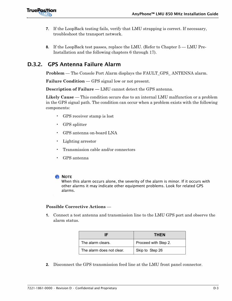
AnyPhone™ LMU 850 MHz Installation Guide
7221-1861-0000 • Revision D • Confidential and Proprietary D-3
7. If the LoopBack testing fails, verify that LMU strapping is correct. If necessary, troubleshoot the transport network.
8. If the LoopBack test passes, replace the LMU. (Refer to Chapter 5 — LMU Pre-Installation and the following chapters 6 through 17).
D.3.2. GPS Antenna Failure Alarm
Problem — The Console Port Alarm displays the FAULT_GPS_ ANTENNA alarm.
Failure Condition — GPS signal low or not present.
Description of Failure — LMU cannot detect the GPS antenna.
Likely Cause — This condition occurs due to an internal LMU malfunction or a problem in the GPS signal path. The condition can occur when a problem exists with the following components:
• GPS receiver stamp is lost
• GPS splitter
• GPS antenna on-board LNA
• Lighting arrestor
• Transmission cable and/or connectors
• GPS antenna
NOTEWhen this alarm occurs alone, the severity of the alarm is minor. If it occurs with other alarms it may indicate other equipment problems. Look for related GPS alarms.
Possible Corrective Actions —
1. Connect a test antenna and transmission line to the LMU GPS port and observe the alarm status.
2. Disconnect the GPS transmission feed line at the LMU front panel connector.
IF THEN
The alarm clears. Proceed with Step 2.
The alarm does not clear. Skip to Step 26
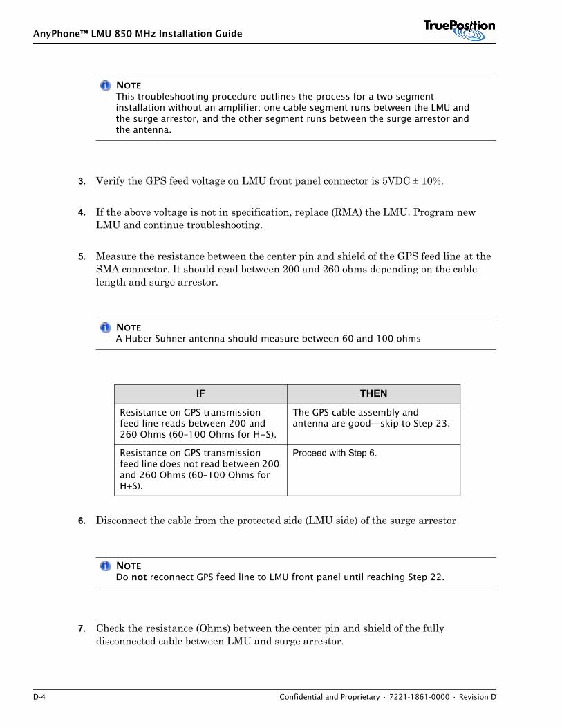
AnyPhone™ LMU 850 MHz Installation Guide
D-4 Confidential and Proprietary • 7221-1861-0000 • Revision D
NOTEThis troubleshooting procedure outlines the process for a two segment installation without an amplifier: one cable segment runs between the LMU and the surge arrestor, and the other segment runs between the surge arrestor and the antenna.
3. Verify the GPS feed voltage on LMU front panel connector is 5VDC ± 10%.
4. If the above voltage is not in specification, replace (RMA) the LMU. Program new LMU and continue troubleshooting.
5. Measure the resistance between the center pin and shield of the GPS feed line at the SMA connector. It should read between 200 and 260 ohms depending on the cable length and surge arrestor.
NOTEA Huber-Suhner antenna should measure between 60 and 100 ohms
6. Disconnect the cable from the protected side (LMU side) of the surge arrestor
NOTEDo not reconnect GPS feed line to LMU front panel until reaching Step 22.
7. Check the resistance (Ohms) between the center pin and shield of the fully disconnected cable between LMU and surge arrestor.
IF THEN
Resistance on GPS transmission feed line reads between 200 and 260 Ohms (60–100 Ohms for H+S).
The GPS cable assembly and antenna are good—skip to Step 23.
Resistance on GPS transmission feed line does not read between 200 and 260 Ohms (60–100 Ohms for H+S).
Proceed with Step 6.
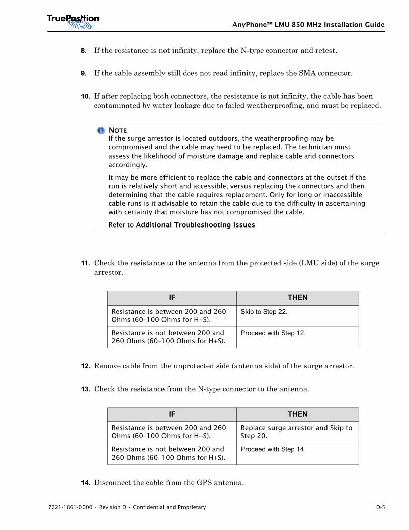
AnyPhone™ LMU 850 MHz Installation Guide
7221-1861-0000 • Revision D • Confidential and Proprietary D-5
8. If the resistance is not infinity, replace the N-type connector and retest.
9. If the cable assembly still does not read infinity, replace the SMA connector.
10. If after replacing both connectors, the resistance is not infinity, the cable has been contaminated by water leakage due to failed weatherproofing, and must be replaced.
NOTEIf the surge arrestor is located outdoors, the weatherproofing may be compromised and the cable may need to be replaced. The technician must assess the likelihood of moisture damage and replace cable and connectors accordingly.
It may be more efficient to replace the cable and connectors at the outset if the run is relatively short and accessible, versus replacing the connectors and then determining that the cable requires replacement. Only for long or inaccessible cable runs is it advisable to retain the cable due to the difficulty in ascertaining with certainty that moisture has not compromised the cable.
Refer to Additional Troubleshooting Issues
11. Check the resistance to the antenna from the protected side (LMU side) of the surge arrestor.
12. Remove cable from the unprotected side (antenna side) of the surge arrestor.
13. Check the resistance from the N-type connector to the antenna.
14. Disconnect the cable from the GPS antenna.
IF THEN
Resistance is between 200 and 260 Ohms (60–100 Ohms for H+S).
Skip to Step 22.
Resistance is not between 200 and 260 Ohms (60–100 Ohms for H+S).
Proceed with Step 12.
IF THEN
Resistance is between 200 and 260 Ohms (60–100 Ohms for H+S).
Replace surge arrestor and Skip to Step 20.
Resistance is not between 200 and 260 Ohms (60–100 Ohms for H+S).
Proceed with Step 14.
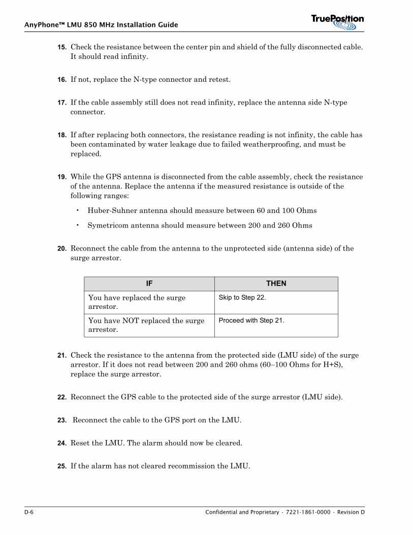
AnyPhone™ LMU 850 MHz Installation Guide
D-6 Confidential and Proprietary • 7221-1861-0000 • Revision D
15. Check the resistance between the center pin and shield of the fully disconnected cable. It should read infinity.
16. If not, replace the N-type connector and retest.
17. If the cable assembly still does not read infinity, replace the antenna side N-type connector.
18. If after replacing both connectors, the resistance reading is not infinity, the cable has been contaminated by water leakage due to failed weatherproofing, and must be replaced.
19. While the GPS antenna is disconnected from the cable assembly, check the resistance of the antenna. Replace the antenna if the measured resistance is outside of the following ranges:
• Huber-Suhner antenna should measure between 60 and 100 Ohms
• Symetricom antenna should measure between 200 and 260 Ohms
20. Reconnect the cable from the antenna to the unprotected side (antenna side) of the surge arrestor.
21. Check the resistance to the antenna from the protected side (LMU side) of the surge arrestor. If it does not read between 200 and 260 ohms (60–100 Ohms for H+S), replace the surge arrestor.
22. Reconnect the GPS cable to the protected side of the surge arrestor (LMU side).
23. Reconnect the cable to the GPS port on the LMU.
24. Reset the LMU. The alarm should now be cleared.
25. If the alarm has not cleared recommission the LMU.
IF THEN
You have replaced the surge arrestor.
Skip to Step 22.
You have NOT replaced the surge arrestor.
Proceed with Step 21.
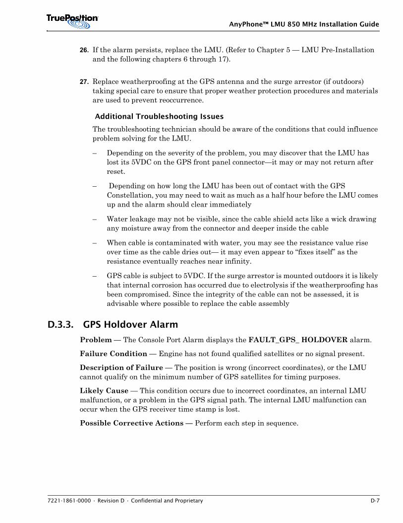
AnyPhone™ LMU 850 MHz Installation Guide
7221-1861-0000 • Revision D • Confidential and Proprietary D-7
26. If the alarm persists, replace the LMU. (Refer to Chapter 5 — LMU Pre-Installation and the following chapters 6 through 17).
27. Replace weatherproofing at the GPS antenna and the surge arrestor (if outdoors) taking special care to ensure that proper weather protection procedures and materials are used to prevent reoccurrence.
Additional Troubleshooting Issues
The troubleshooting technician should be aware of the conditions that could influence problem solving for the LMU.
– Depending on the severity of the problem, you may discover that the LMU has lost its 5VDC on the GPS front panel connector—it may or may not return after reset.
– Depending on how long the LMU has been out of contact with the GPS Constellation, you may need to wait as much as a half hour before the LMU comes up and the alarm should clear immediately
– Water leakage may not be visible, since the cable shield acts like a wick drawing any moisture away from the connector and deeper inside the cable
– When cable is contaminated with water, you may see the resistance value rise over time as the cable dries out— it may even appear to “fixes itself” as the resistance eventually reaches near infinity.
– GPS cable is subject to 5VDC. If the surge arrestor is mounted outdoors it is likely that internal corrosion has occurred due to electrolysis if the weatherproofing has been compromised. Since the integrity of the cable can not be assessed, it is advisable where possible to replace the cable assembly
D.3.3. GPS Holdover Alarm
Problem — The Console Port Alarm displays the FAULT_GPS_ HOLDOVER alarm.
Failure Condition — Engine has not found qualified satellites or no signal present.
Description of Failure — The position is wrong (incorrect coordinates), or the LMU cannot qualify on the minimum number of GPS satellites for timing purposes.
Likely Cause — This condition occurs due to incorrect coordinates, an internal LMU malfunction, or a problem in the GPS signal path. The internal LMU malfunction can occur when the GPS receiver time stamp is lost.
Possible Corrective Actions — Perform each step in sequence.
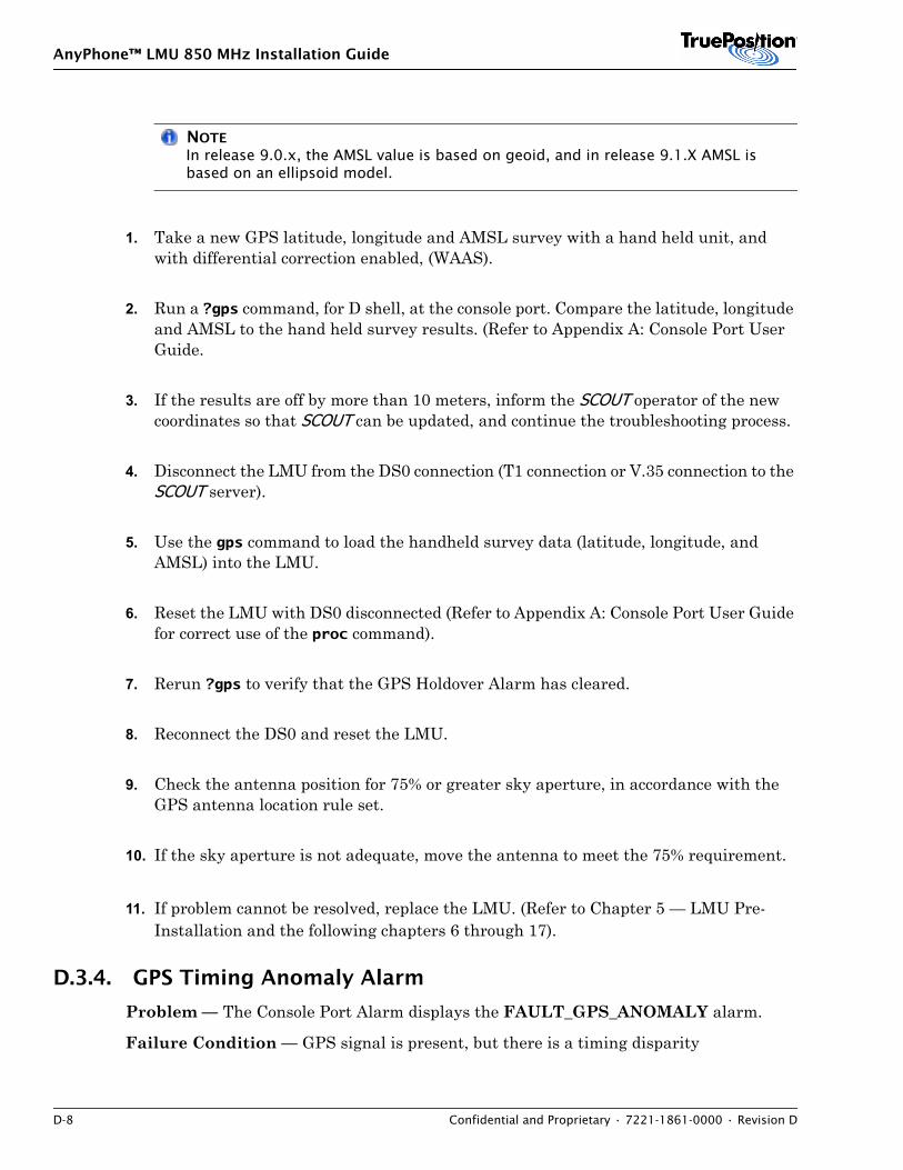
AnyPhone™ LMU 850 MHz Installation Guide
D-8 Confidential and Proprietary • 7221-1861-0000 • Revision D
NOTEIn release 9.0.x, the AMSL value is based on geoid, and in release 9.1.X AMSL is based on an ellipsoid model.
1. Take a new GPS latitude, longitude and AMSL survey with a hand held unit, and with differential correction enabled, (WAAS).
2. Run a ?gps command, for D shell, at the console port. Compare the latitude, longitude and AMSL to the hand held survey results. (Refer to Appendix A: Console Port User Guide.
3. If the results are off by more than 10 meters, inform the SCOUT operator of the new coordinates so that SCOUT can be updated, and continue the troubleshooting process.
4. Disconnect the LMU from the DS0 connection (T1 connection or V.35 connection to the SCOUT server).
5. Use the gps command to load the handheld survey data (latitude, longitude, and AMSL) into the LMU.
6. Reset the LMU with DS0 disconnected (Refer to Appendix A: Console Port User Guide for correct use of the proc command).
7. Rerun ?gps to verify that the GPS Holdover Alarm has cleared.
8. Reconnect the DS0 and reset the LMU.
9. Check the antenna position for 75% or greater sky aperture, in accordance with the GPS antenna location rule set.
10. If the sky aperture is not adequate, move the antenna to meet the 75% requirement.
11. If problem cannot be resolved, replace the LMU. (Refer to Chapter 5 — LMU Pre-Installation and the following chapters 6 through 17).
D.3.4. GPS Timing Anomaly Alarm
Problem — The Console Port Alarm displays the FAULT_GPS_ANOMALY alarm.
Failure Condition — GPS signal is present, but there is a timing disparity
AnyPhone™ LMU 850 MHz Installation Guide
7221-1861-0000 • Revision D • Confidential and Proprietary D-9
Description of Failure — A problem exists with the GPS timing. The LMU may not participate in location processing.
Likely Cause —
• Poor sky aperture (incorrect antenna location).
• Poor GDOP (Geometric Dilution of Precision).
• Error in GPS antenna survey (latitude, longitude and AMSL).
Possible Corrective Actions — (Perform each step in sequence until the problem is fixed)
NOTE9.0.x AMSL is based on to geoid and 9.1.X AMSL is based on ellipsoid
1. Take a new GPS latitude, longitude and AMSL survey with a hand held unit, with differential correction enabled, (WAAS).
2. Run a ?gps command at the console port. Compare the latitude, longitude and AMSL to the hand held survey results.
3. If the results are off by more than 10 meters, inform the SCOUT operator of the new coordinates so that SCOUT can be updated, and continue the troubleshooting process.
4. Disconnect the LMU from the DS0 connection (T1 connection or V.35 connection to the SCOUT server).
5. Use the gps command to load the handheld survey data (latitude, longitude, and AMSL) into the LMU.
6. Reset the LMU with DS0 disconnected (Refer to Appendix A: Console Port User Guide for correct use of the proc command).
7. Rerun ?gps to verify that the GPS Holdover Alarm has cleared.
8. Reconnect the DS0 and reset the LMU.
9. Check the antenna position for 75% or greater sky aperture, in accordance with the GPS antenna location rule set.
AnyPhone™ LMU 850 MHz Installation Guide
D-10 Confidential and Proprietary • 7221-1861-0000 • Revision D
10. If the sky aperture is not adequate, move the antenna to meet the 75% requirement.
11. If problem cannot be resolved, replace the LMU. (Refer to Chapter 5 — LMU Pre-Installation and the following chapters 6 through 17).
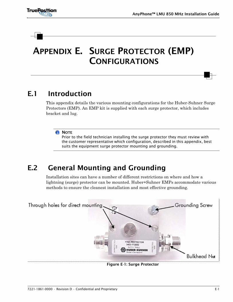
AnyPhone™ LMU 850 MHz Installation Guide
7221-1861-0000 • Revision D • Confidential and Proprietary E-1
APPENDIX E. SURGE PROTECTOR (EMP) CONFIGURATIONS
E.1 IntroductionThis appendix details the various mounting configurations for the Huber-Suhner Surge Protectors (EMP). An EMP kit is supplied with each surge protector, which includes bracket and lug.
NOTEPrior to the field technician installing the surge protector they must review with the customer representative which configuration, described in this appendix, best suits the equipment surge protector mounting and grounding.
E.2 General Mounting and GroundingInstallation sites can have a number of different restrictions on where and how a lightning (surge) protector can be mounted. Huber+Suhner EMPs accommodate various methods to ensure the cleanest installation and most effective grounding.
Figure E-1: Surge Protector
ut
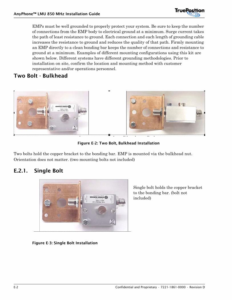
AnyPhone™ LMU 850 MHz Installation Guide
E-2 Confidential and Proprietary • 7221-1861-0000 • Revision D
EMPs must be well grounded to properly protect your system. Be sure to keep the number of connections from the EMP body to electrical ground at a minimum. Surge current takes the path of least resistance to ground. Each connection and each length of grounding cable increases the resistance to ground and reduces the quality of that path. Firmly mounting an EMP directly to a clean bonding bar keeps the number of connections and resistance to ground at a minimum. Examples of different mounting configurations using this kit are shown below. Different systems have different grounding methodologies. Prior to installation on site, confirm the location and mounting method with customer representative and/or operations personnel.
Two Bolt - Bulkhead
Figure E-2: Two Bolt, Bulkhead Installation
Two bolts hold the copper bracket to the bonding bar. EMP is mounted via the bulkhead nut. Orientation does not matter. (two mounting bolts not included)
E.2.1. Single Bolt
Single bolt holds the copper bracket to the bonding bar. (bolt not included)
Figure E-3: Single Bolt Installation
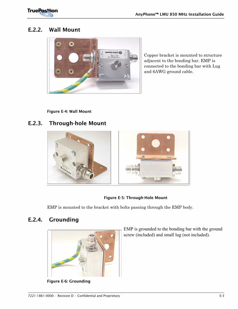
AnyPhone™ LMU 850 MHz Installation Guide
7221-1861-0000 • Revision D • Confidential and Proprietary E-3
E.2.2. Wall Mount
Copper bracket is mounted to structure adjacent to the bonding bar. EMP is connected to the bonding bar with Lug and 6AWG ground cable.
Figure E-4: Wall Mount
E.2.3. Through-hole Mount
Figure E-5: Through-Hole Mount
EMP is mounted to the bracket with bolts passing through the EMP body.
E.2.4. Grounding
EMP is grounded to the bonding bar with the ground screw (included) and small lug (not included).
Figure E-6: Grounding

AnyPhone™ LMU 850 MHz Installation Guide
E-4 Confidential and Proprietary • 7221-1861-0000 • Revision D
AnyPhone™ LMU 850 MHz Installation Guide
7221-1861-0000 • Revision D • Confidential and Proprietary Glossary-1
Glossary
Acronym or Term Definition
100BASE-T Also known as Fast Ethernet, an Ethernet technology that supports a data transfer rate of 100 megabits per second over special grades of twisted-pair wiring.
10BASE-T A 10BASE-T network has a data transfer rate of 10 megabits per second and uses unshielded twisted-pair wiring with RJ45 modular telephone plugs and sockets.
ADPn Analog Data Path (n) where n is the path number.
AGL Above ground level
Amp Ampere (a unit of electrical current)
AMPS Advanced mobile phone system (or service); TIA analog cellular, and all standards that retain compatibility with it (NAMPS, D-AMPS, CDMA)
AMS Abis Monitoring System
ANSI American National Standards Institute
ANT Antenna
AOA Angle of Arrival. A technique for locating a radio by estimating the angle of signal arrival at multiple points. Compare with TOA.
AP Application processor
API Application Program Interface
ASCII American Standard Code for Information Interchange – standard code set for numbers, letters, and other symbols
ASIC Application-specific integrated circuit
AVC Analog Voice Channel
AWG American wire gauge
Backhaul Telecommunications facilities (e.g., copper, microwave, fiber) which carry voice and/or data from one point to another, typically from remote locations (e.g.,cell sites) to central locations (e.g., mobile switching centers).
Band Range of frequencies used for transmitting a signal
BCCH Broadcast Control Channel
BFDB Battery Distribution Fuse Breaker
AnyPhone™ LMU 850 MHz Installation Guide
Glossary-2 Confidential and Proprietary • 7221-1861-0000 • Revision D
Bit An acronym for the term ‘binary digit’ which is the base numbering system for digital electronic systems. A bit has two possible values, 0 or 1.
BIT Built-in test
Bit Sync Bit synchronizer
BTS Base Transceiver Station
BNC Bayonet normalized connector
boot To load the system software into memory and start it running.
bps Bits Per Second/Baud rate
BPV Bipolar Violation
BSC Base Station Controller
BSIC Base Station Identity Code
BSSLAP Base Station Subsystem LCS Assistance Protocol
BTS Base Transceiver Station
C/O Checked Out
CAT5 Ethernet cable standard defined by the Electronic Industries Association
CDPD Cellular Digital Packet Data
CGI+TA Cell ID and Timing Advance
CHAP Challenge Handshake Authentication Protocol
CLLI Code Common Language Location Identifier Code
Cluster For the LMU, a group of LMUs that are in the same geographical area and share the same switch ID and SMLC. Also used to refer to the TruePosition equipment at a MTSO, including the WLG, SMLC, EMS and SCOUT™ application servers, routers and switches.
Configuration The functional arrangement of a managed object, attributes, or process.
CP Communication Processor
CP Control processor; CPU in the LMU; communication processor
CP/DSP Control Processor/Digital Signal Processor
cPCI Compact Personal Computer Interface
CPU Central Processing Unit
CRC Cyclic Redundancy Check. A method (similar to checksum) for detecting data transmission errors
cron UNIX utility that runs commands in a crontab file at a specific time and date; used to schedule backup and maintenance functions.
crontab The table that defines scheduled tasks for the cron daemon
Acronym or Term Definition
AnyPhone™ LMU 850 MHz Installation Guide
7221-1861-0000 • Revision D • Confidential and Proprietary Glossary-3
CSMA/CD Carrier Sense Multiple Access/Collision Detection. The access protocol for Ethernet networks.
CSV Comma Separated Values
CTM Centralized Technical Management
CTRL Control key
DACS Digital Access Cross-Connect
DAT Digital Audio Tape
dB Decibel – 10 (or 20) times the base 10 logarithm of a ratio. Use 20 if discussing volts, 10 if power
DB (or db) Database
dBm The Ratio of the Power to One milliwatt Expressed in Decibels
DDC Digital Down Converter
DEM Digital Elevation Map
Digital Transmission of information through a discrete signal (e.g. bits with values 0 or 1). Compare with analog
DIMM Dual In Line Memory Module
DLT Digital Linear Tape
DMA Direct Memory Address
Docket 94-102 The FCC revised rules for Enhanced 911 wireless location services. See http://www.fcc.gov/911/enhanced/releases/factsheet_requirements_012001.pdf
DPC Destination Point Code
DPn Data Path (n) where n is the path number
DRAM Dynamic random-access memory. Read/write dynamic memory in which the data can be read or written in approximately the same amount of time for any memory location.
DS0 Digital Signal 0 - a single T1 channel with bandwidth of 64kbps (8 bits x 8,000 samples per second) the capacity used for a single voice conversation.
DSP Digital Signal Processor
DT Drive Test
DTC Drive Test Client; Digital Traffic Channel
DTS Drive Test Server
DTT Drive Test Tool
DVD Digital Video Disk
DVM Digital voltage meter
Acronym or Term Definition
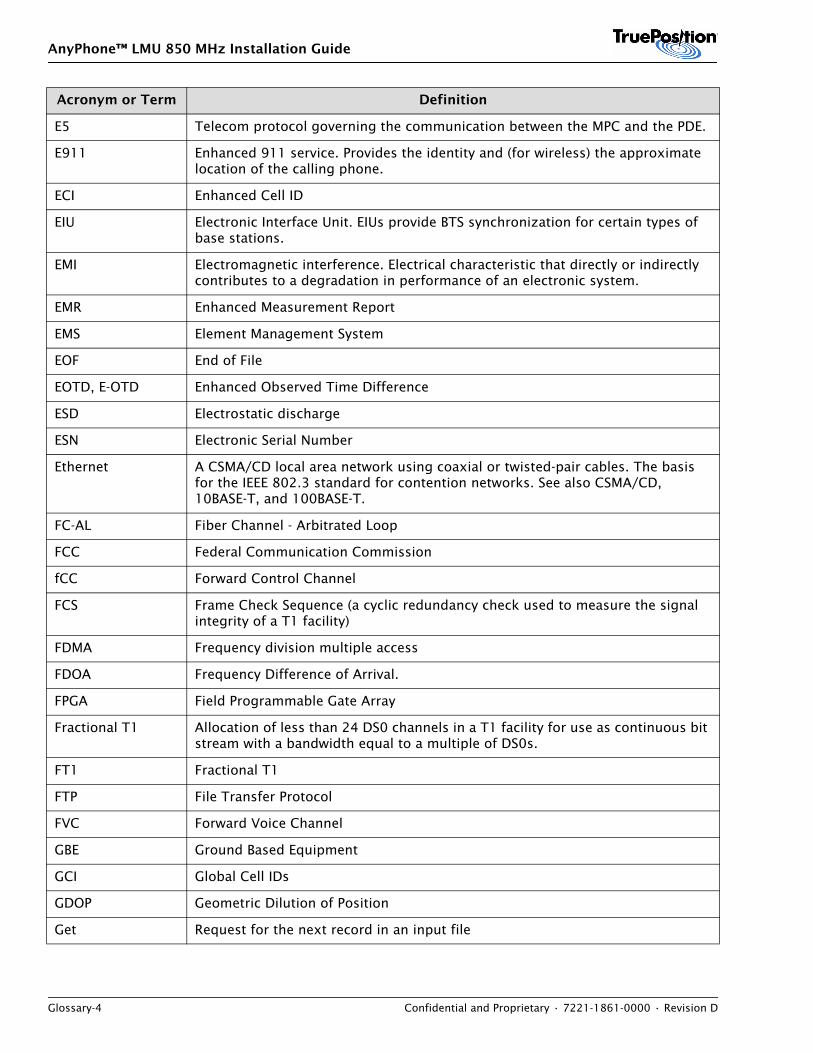
AnyPhone™ LMU 850 MHz Installation Guide
Glossary-4 Confidential and Proprietary • 7221-1861-0000 • Revision D
E5 Telecom protocol governing the communication between the MPC and the PDE.
E911 Enhanced 911 service. Provides the identity and (for wireless) the approximate location of the calling phone.
ECI Enhanced Cell ID
EIU Electronic Interface Unit. EIUs provide BTS synchronization for certain types of base stations.
EMI Electromagnetic interference. Electrical characteristic that directly or indirectly contributes to a degradation in performance of an electronic system.
EMR Enhanced Measurement Report
EMS Element Management System
EOF End of File
EOTD, E-OTD Enhanced Observed Time Difference
ESD Electrostatic discharge
ESN Electronic Serial Number
Ethernet A CSMA/CD local area network using coaxial or twisted-pair cables. The basis for the IEEE 802.3 standard for contention networks. See also CSMA/CD, 10BASE-T, and 100BASE-T.
FC-AL Fiber Channel - Arbitrated Loop
FCC Federal Communication Commission
fCC Forward Control Channel
FCS Frame Check Sequence (a cyclic redundancy check used to measure the signal integrity of a T1 facility)
FDMA Frequency division multiple access
FDOA Frequency Difference of Arrival.
FPGA Field Programmable Gate Array
Fractional T1 Allocation of less than 24 DS0 channels in a T1 facility for use as continuous bit stream with a bandwidth equal to a multiple of DS0s.
FT1 Fractional T1
FTP File Transfer Protocol
FVC Forward Voice Channel
GBE Ground Based Equipment
GCI Global Cell IDs
GDOP Geometric Dilution of Position
Get Request for the next record in an input file
Acronym or Term Definition
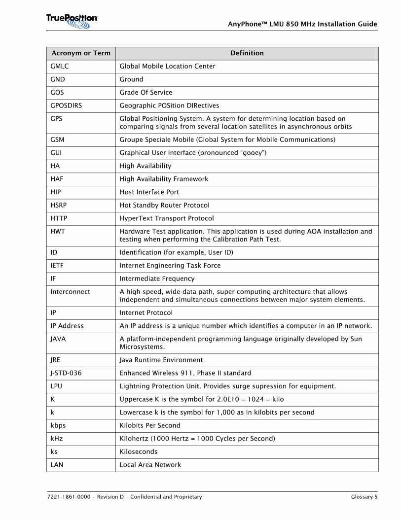
AnyPhone™ LMU 850 MHz Installation Guide
7221-1861-0000 • Revision D • Confidential and Proprietary Glossary-5
GMLC Global Mobile Location Center
GND Ground
GOS Grade Of Service
GPOSDIRS Geographic POSition DIRectives
GPS Global Positioning System. A system for determining location based on comparing signals from several location satellites in asynchronous orbits
GSM Groupe Speciale Mobile (Global System for Mobile Communications)
GUI Graphical User Interface (pronounced “gooey”)
HA High Availability
HAF High Availability Framework
HIP Host Interface Port
HSRP Hot Standby Router Protocol
HTTP HyperText Transport Protocol
HWT Hardware Test application. This application is used during AOA installation and testing when performing the Calibration Path Test.
ID Identification (for example, User ID)
IETF Internet Engineering Task Force
IF Intermediate Frequency
Interconnect A high-speed, wide-data path, super computing architecture that allows independent and simultaneous connections between major system elements.
IP Internet Protocol
IP Address An IP address is a unique number which identifies a computer in an IP network.
JAVA A platform-independent programming language originally developed by Sun Microsystems.
JRE Java Runtime Environment
J-STD-036 Enhanced Wireless 911, Phase II standard
LPU Lightning Protection Unit. Provides surge supression for equipment.
K Uppercase K is the symbol for 2.0E10 = 1024 = kilo
k Lowercase k is the symbol for 1,000 as in kilobits per second
kbps Kilobits Per Second
kHz Kilohertz (1000 Hertz = 1000 Cycles per Second)
ks Kiloseconds
LAN Local Area Network
Acronym or Term Definition
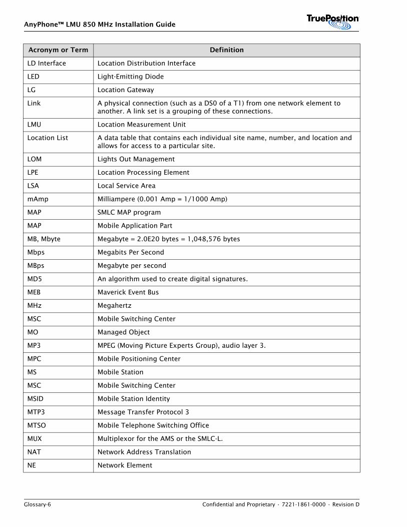
AnyPhone™ LMU 850 MHz Installation Guide
Glossary-6 Confidential and Proprietary • 7221-1861-0000 • Revision D
LD Interface Location Distribution Interface
LED Light-Emitting Diode
LG Location Gateway
Link A physical connection (such as a DS0 of a T1) from one network element to another. A link set is a grouping of these connections.
LMU Location Measurement Unit
Location List A data table that contains each individual site name, number, and location and allows for access to a particular site.
LOM Lights Out Management
LPE Location Processing Element
LSA Local Service Area
mAmp Milliampere (0.001 Amp = 1/1000 Amp)
MAP SMLC MAP program
MAP Mobile Application Part
MB, Mbyte Megabyte = 2.0E20 bytes = 1,048,576 bytes
Mbps Megabits Per Second
MBps Megabyte per second
MD5 An algorithm used to create digital signatures.
MEB Maverick Event Bus
MHz Megahertz
MSC Mobile Switching Center
MO Managed Object
MP3 MPEG (Moving Picture Experts Group), audio layer 3.
MPC Mobile Positioning Center
MS Mobile Station
MSC Mobile Switching Center
MSID Mobile Station Identity
MTP3 Message Transfer Protocol 3
MTSO Mobile Telephone Switching Office
MUX Multiplexor for the AMS or the SMLC-L.
NAT Network Address Translation
NE Network Element
Acronym or Term Definition
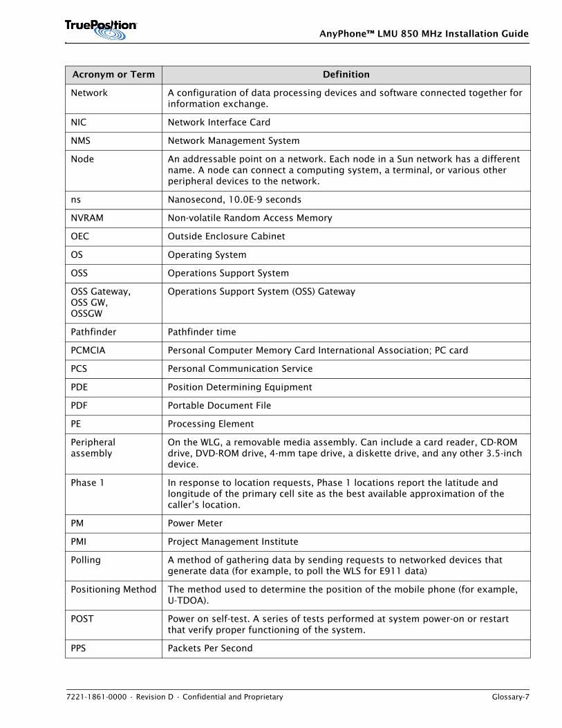
AnyPhone™ LMU 850 MHz Installation Guide
7221-1861-0000 • Revision D • Confidential and Proprietary Glossary-7
Network A configuration of data processing devices and software connected together for information exchange.
NIC Network Interface Card
NMS Network Management System
Node An addressable point on a network. Each node in a Sun network has a different name. A node can connect a computing system, a terminal, or various other peripheral devices to the network.
ns Nanosecond, 10.0E-9 seconds
NVRAM Non-volatile Random Access Memory
OEC Outside Enclosure Cabinet
OS Operating System
OSS Operations Support System
OSS Gateway, OSS GW, OSSGW
Operations Support System (OSS) Gateway
Pathfinder Pathfinder time
PCMCIA Personal Computer Memory Card International Association; PC card
PCS Personal Communication Service
PDE Position Determining Equipment
PDF Portable Document File
PE Processing Element
Peripheral assembly
On the WLG, a removable media assembly. Can include a card reader, CD-ROM drive, DVD-ROM drive, 4-mm tape drive, a diskette drive, and any other 3.5-inch device.
Phase 1 In response to location requests, Phase 1 locations report the latitude and longitude of the primary cell site as the best available approximation of the caller’s location.
PM Power Meter
PMI Project Management Institute
Polling A method of gathering data by sending requests to networked devices that generate data (for example, to poll the WLS for E911 data)
Positioning Method The method used to determine the position of the mobile phone (for example, U-TDOA).
POST Power on self-test. A series of tests performed at system power-on or restart that verify proper functioning of the system.
PPS Packets Per Second
Acronym or Term Definition
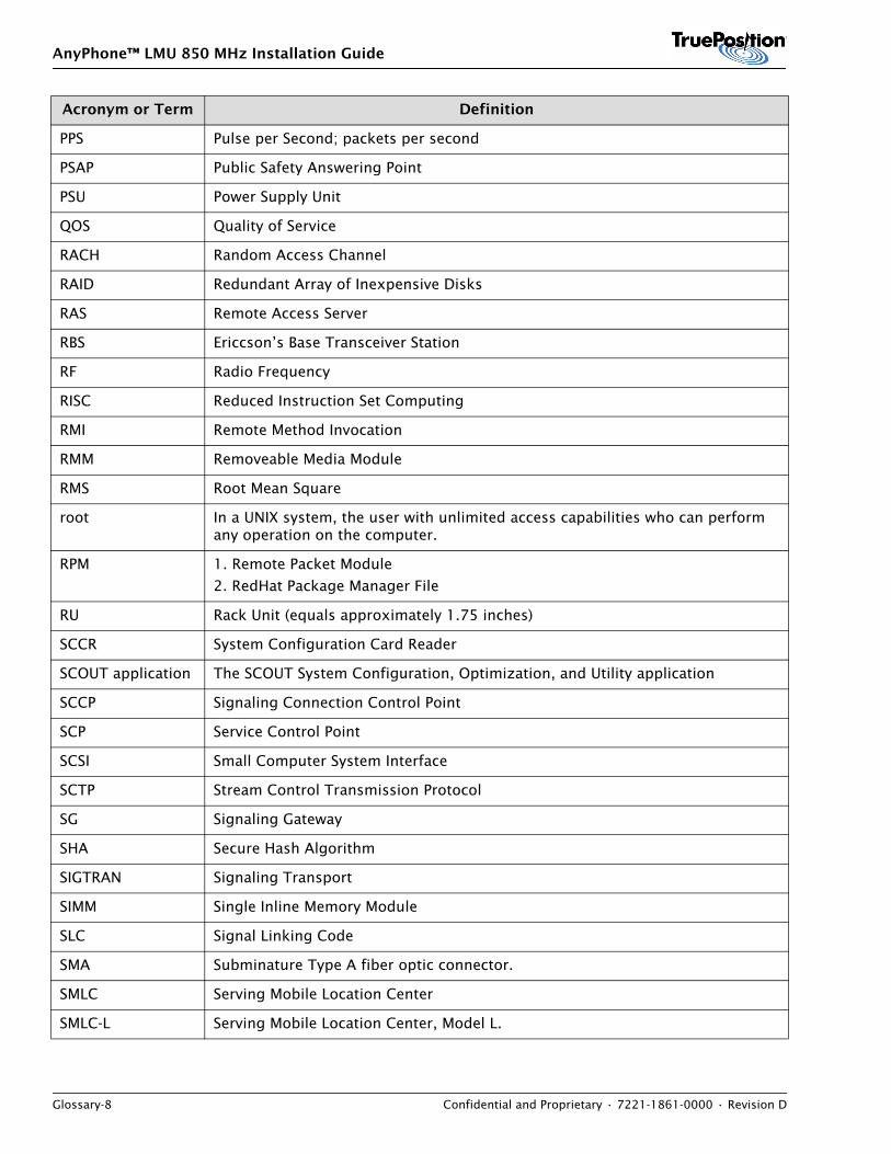
AnyPhone™ LMU 850 MHz Installation Guide
Glossary-8 Confidential and Proprietary • 7221-1861-0000 • Revision D
PPS Pulse per Second; packets per second
PSAP Public Safety Answering Point
PSU Power Supply Unit
QOS Quality of Service
RACH Random Access Channel
RAID Redundant Array of Inexpensive Disks
RAS Remote Access Server
RBS Ericcson’s Base Transceiver Station
RF Radio Frequency
RISC Reduced Instruction Set Computing
RMI Remote Method Invocation
RMM Removeable Media Module
RMS Root Mean Square
root In a UNIX system, the user with unlimited access capabilities who can perform any operation on the computer.
RPM 1. Remote Packet Module
2. RedHat Package Manager File
RU Rack Unit (equals approximately 1.75 inches)
SCCR System Configuration Card Reader
SCOUT application The SCOUT System Configuration, Optimization, and Utility application
SCCP Signaling Connection Control Point
SCP Service Control Point
SCSI Small Computer System Interface
SCTP Stream Control Transmission Protocol
SG Signaling Gateway
SHA Secure Hash Algorithm
SIGTRAN Signaling Transport
SIMM Single Inline Memory Module
SLC Signal Linking Code
SMA Subminature Type A fiber optic connector.
SMLC Serving Mobile Location Center
SMLC-L Serving Mobile Location Center, Model L.
Acronym or Term Definition
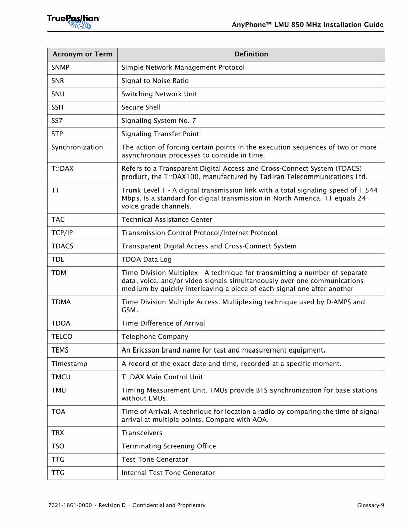
AnyPhone™ LMU 850 MHz Installation Guide
7221-1861-0000 • Revision D • Confidential and Proprietary Glossary-9
SNMP Simple Network Management Protocol
SNR Signal-to-Noise Ratio
SNU Switching Network Unit
SSH Secure Shell
SS7 Signaling System No. 7
STP Signaling Transfer Point
Synchronization The action of forcing certain points in the execution sequences of two or more asynchronous processes to coincide in time.
T::DAX Refers to a Transparent Digital Access and Cross-Connect System (TDACS) product, the T::DAX100, manufactured by Tadiran Telecommunications Ltd.
T1 Trunk Level 1 - A digital transmission link with a total signaling speed of 1.544 Mbps. Is a standard for digital transmission in North America. T1 equals 24 voice grade channels.
TAC Technical Assistance Center
TCP/IP Transmission Control Protocol/Internet Protocol
TDACS Transparent Digital Access and Cross-Connect System
TDL TDOA Data Log
TDM Time Division Multiplex - A technique for transmitting a number of separate data, voice, and/or video signals simultaneously over one communications medium by quickly interleaving a piece of each signal one after another
TDMA Time Division Multiple Access. Multiplexing technique used by D-AMPS and GSM.
TDOA Time Difference of Arrival
TELCO Telephone Company
TEMS An Ericsson brand name for test and measurement equipment.
Timestamp A record of the exact date and time, recorded at a specific moment.
TMCU T::DAX Main Control Unit
TMU Timing Measurement Unit. TMUs provide BTS synchronization for base stations without LMUs.
TOA Time of Arrival. A technique for location a radio by comparing the time of signal arrival at multiple points. Compare with AOA.
TRX Transceivers
TSO Terminating Screening Office
TTG Test Tone Generator
TTG Internal Test Tone Generator
Acronym or Term Definition
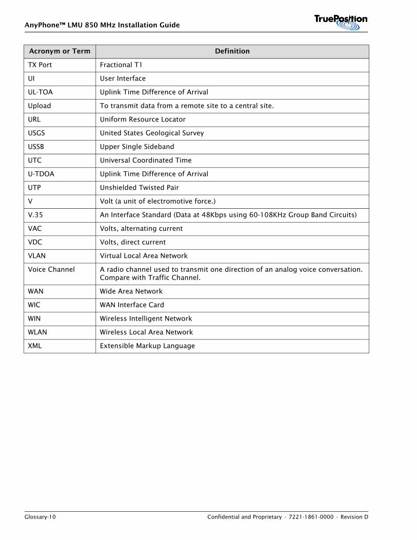
AnyPhone™ LMU 850 MHz Installation Guide
Glossary-10 Confidential and Proprietary • 7221-1861-0000 • Revision D
TX Port Fractional T1
UI User Interface
UL-TOA Uplink Time Difference of Arrival
Upload To transmit data from a remote site to a central site.
URL Uniform Resource Locator
USGS United States Geological Survey
USSB Upper Single Sideband
UTC Universal Coordinated Time
U-TDOA Uplink Time Difference of Arrival
UTP Unshielded Twisted Pair
V Volt (a unit of electromotive force.)
V.35 An Interface Standard (Data at 48Kbps using 60-108KHz Group Band Circuits)
VAC Volts, alternating current
VDC Volts, direct current
VLAN Virtual Local Area Network
Voice Channel A radio channel used to transmit one direction of an analog voice conversation. Compare with Traffic Channel.
WAN Wide Area Network
WIC WAN Interface Card
WIN Wireless Intelligent Network
WLAN Wireless Local Area Network
XML Extensible Markup Language
Acronym or Term Definition


7221-1862-0000 Revision C