Embed Size (px)
Citation preview

REVISION DATED DESCRIPTION AUTHOR APPROVED
3 01/11/04 Change to new format PC TMcL
4 12/12/06 Section 16 Revised PC TMcL
5 14/06/07 WIS 1211 Corrected PC TMcL
6 21/09/07 Updated Sequences PC DF
7 08/02/08 Table of Contents Added PC DF
8 05/08/08 EC Declaration added KU TMcL
9 15/05/09 Fig 13.4 Corrected PC DA
10 26/05/09 Fig 6.1, 6.2 & 13.3 Corrected PC DA
11 1/12/09 Baseefa notified body number added and declaration updated
WF PH
12 24/04/12 D of C updated in line with current standards
BC WF
13 06/09/2012 Date error in D of C corrected NG WF
14 12/11/2012 D of C updated in line with current standards
WF PH
15 11/12/2012 Input connection drawings updated
DF BC
LN
1000 Intrin
sically Safe A
nn
un
ciator

2
© RTK Instruments LTD 2004 The copyright in this work is vested in RTK Instruments Ltd and this document is issued for the purpose only for which it is supplied. No licence is implied for the use of any patented feature. It must not be reproduced in whole or in part, or used for tendering or manufacturing purposes except under an agreement or with the consent in writing of RTK Instruments Ltd and then only on the condition that this notice is included in any such reproduction. Information furnished is believed to be accurate but no liability in respect of any use of it is accepted by RTK Instruments Ltd.
LN1000 IS Annunciator
3
TABLE OF CONTENTS
TABLE OF CONTENTS .............................................................................................. 3
SECTION 1 INTRODUCTION ..................................................................................... 6
SECTION 2 SYSTEM DESCRIPTION & FEATURES ................................................ 7
GENERAL .............................................................................................................................. 7 CERTIFICATION ...................................................................................................................... 7 SYSTEM SIZES....................................................................................................................... 7 COMPLETE SYSTEM ............................................................................................................... 7 PROGRAMMABILITY ................................................................................................................ 7 MOUNTING ............................................................................................................................ 7 SERVICING ............................................................................................................................ 8 LIGHTWEIGHT ........................................................................................................................ 8 GROUP OUTPUTS .................................................................................................................. 8 INPUTS .................................................................................................................................. 8
SECTION 3 INPUTS & OUTPUTS ............................................................................ 10
TERMINATIONS AND INTERCONNECTIONS .............................................................................. 10 LN1000-AC ALARM CARD ................................................................................................... 10 LN1000-SC SEQUENCE CARD ............................................................................................. 10
SECTION 4 TECHNICAL SPECIFICATION ............................................................. 11
LOCATION ........................................................................................................................... 11 POWER REQUIREMENTS ...................................................................................................... 11 TERMINALS .......................................................................................................................... 11 EMC COMPLIANCE ............................................................................................................... 11 ENVIRONMENT ..................................................................................................................... 11 ENVIRONMENTAL PROTECTION ............................................................................................ 11 CONSTRUCTION ................................................................................................................... 11 PANEL CUT OUT .................................................................................................................. 11 WEIGHT .............................................................................................................................. 11 ALARM INPUTS .................................................................................................................... 12 INHIBIT INPUTS .................................................................................................................... 12 ALARM OUTPUTS ................................................................................................................. 12 PROGRAMMABLE FEATURES ................................................................................................ 13 LN1000-SC SEQUENCE CARD ............................................................................................. 13 INPUT .................................................................................................................................. 13 OUTPUTS ............................................................................................................................ 13 PUSH BUTTONS ................................................................................................................... 14 OTHER FEATURES ............................................................................................................... 14
SECTION 5 MECHANICAL DETAILS ...................................................................... 15
ALARM CHASSIS .................................................................................................................. 15 FASCIA PANEL ..................................................................................................................... 15 ALARM CARDS ..................................................................................................................... 15 SEQUENCE CARD ................................................................................................................ 15 PANEL MOUNTING ............................................................................................................... 15 WALL MOUNTING ................................................................................................................. 16

4
CHANNEL NUMBERING ......................................................................................................... 16
SECTION 6 ALARM SEQUENCES .......................................................................... 21
SUMMARY ........................................................................................................................... 21 FIRST-UP SEQUENCE ........................................................................................................... 21 AUTO RESET SEQUENCE ...................................................................................................... 22 RINGBACK SEQUENCE .......................................................................................................... 22
SECTION 7 SEQUENCE TABLES ........................................................................... 23
ISA – M MANUAL RESET ...................................................................................................... 23 ISA – A AUTO RESET .......................................................................................................... 24 ISA – R RINGBACK .............................................................................................................. 25 ISA – F1A FIRST-UP AUTOMATIC RESET .............................................................................. 26 ISA – F2M-1 FIRST-UP WITH MANUAL RESET ....................................................................... 27 ISA – F3A FIRST-UP WITH AUTOMATIC RESET ...................................................................... 29
SECTION 8 MOUNTING ........................................................................................... 31
PANEL MOUNTING VERSION .................................................................................................. 31 REMOVAL ............................................................................................................................ 31 REMOVAL / REPLACEMENT OF SEQUENCE AND ALARM CARDS .............................................. 33 IDENTIFICATION LEGENDS .................................................................................................... 35
SECTION 9 FIELD WIRING ...................................................................................... 36
CERTIFICATION .................................................................................................................... 36 GENERAL ............................................................................................................................ 36
SECTION 10 TERMINAL NUMBERS ....................................................................... 38
SEQUENCE CARD TERMINAL NUMBERING: ............................................................................ 38 ALARM CARD TERMINAL NUMBERING: .................................................................................. 38
SECTION 11 SYSTEM SUPPLY CONNECTIONS ................................................... 39
POWER SUPPLY .................................................................................................................. 39
SECTION 12 SYSTEM INPUT CONNECTIONS ....................................................... 40
ALARM INPUTS - HAZARDOUS AREAS .................................................................................... 40 INHIBIT INPUTS .................................................................................................................... 44 EXTERNAL PUSHBUTTON INPUTS .......................................................................................... 44
SECTION 13 SYSTEM OUTPUT CONNECTIONS ................................................... 45
GENERAL ............................................................................................................................ 45 AUDIBLE OUTPUTS ............................................................................................................... 45 COMMON OUTPUTS .............................................................................................................. 47 B1 OUTPUT ......................................................................................................................... 47 B2 OUTPUT ......................................................................................................................... 47 ALARM OUTPUTS ................................................................................................................. 48 ALARM CONTACT REPEAT OUTPUTS ...................................................................................... 49
SECTION 14 SYSTEM CONFIGURATION & PROGRAMMING .............................. 50
GENERAL ............................................................................................................................ 50 COMMONS CARD DIL SWITCH SETTINGS .............................................................................. 50 B1 OUTPUT ......................................................................................................................... 51 AUDIBLE RE-SOUND ............................................................................................................. 51
LN1000 IS Annunciator
5
AUDIBLE RE-SOUND TABLE ................................................................................................... 51 INTEGRAL PUSHBUTTON LINKS ............................................................................................. 51 ALARM CARD DIL SWITCH SETTINGS ................................................................................... 52 GROUP TRIP OUTPUTS ........................................................................................................ 53 GROUP TRIP A .................................................................................................................... 53 GROUP TRIP B .................................................................................................................... 53 B1 FIELD CONTACT GROUP ................................................................................................. 53 ALARM INPUT DELAY ........................................................................................................... 54 FIELD CONTACT MODE ........................................................................................................ 54 FIRST-UP GROUP ................................................................................................................ 54 FIRST UP GROUP TABLE ....................................................................................................... 54 ALARM SEQUENCE .............................................................................................................. 54 ALARM SEQUENCE TABLE ..................................................................................................... 55
SECTION 15 COMMISSIONING ............................................................................... 56
TOOLS REQUIRED ................................................................................................................ 56 COMMISSIONING .................................................................................................................. 56
SECTION 16 TROUBLE SHOOTING ....................................................................... 57
THERE IS NO DISPLAYS VISIBLE ON EITHER LCD OR LED - CHECK ......................................... 57 DISPLAYS DO NOT OPERATE WHEN TEST PUSHBUTTON PRESSED - CHECK ............................. 57 ALL ALARM CHANNELS FUNCTION INCORRECTLY - CHECK ...................................................... 57 ONE CHANNEL FUNCTIONS INCORRECTLY - CHECK ................................................................ 57 THE DIL SWITCH PROGRAMMING DOES NOT FUNCTION - CHECK ............................................ 57 THE AUDIBLE IS NOT WORKING CORRECTLY - CHECK ............................................................. 57 THE IS RELAYS ARE NOT SWITCHING CORRECTLY - CHECK ................................................... 58 ROUTINE MAINTENANCE ....................................................................................................... 58 RECOMMENDED SPARES ..................................................................................................... 58
SECTION 17 APPENDIX A ....................................................................................... 59
CABLE PARAMETERS ........................................................................................................... 59 A1: SAFE AREA APPARATUS ........................................................................................... 59 A2: COMMONS CARD B1, B2, AND EXT. SOUND OUTPUTS ............................................... 59 A3: COMMONS CARD IS HORN OUTPUT .......................................................................... 59 A4: COMMONS CARD REMOTE PUSHBUTTON STATION .................................................... 60 A5: ALARM CARD CONNECTIONS .................................................................................... 60
LN1000 ANTI-STATIC PRECAUTIONS ................................................................... 61
EC DECLARATION OF CONFORMITY ................................................................... 62
OTHER RTK PRODUCTS ........................................................................................ 63
6
SECTION 1 INTRODUCTION The LN1000 annunciator is an intrinsically safe process alarm system certified for installation in Zones 0, 1, 2 IIB and IIC hazardous areas. The annunciator is a totally unique product which provides an ideal solution to alarm monitoring problems where an operator needs additional information on the plant status and control over external parts of the plant. Being certified to Ex ia means there are no restrictions with regard to maintenance whilst the power is applied as there are with Ex d, Ex p or Ex N equipment. The annunciator system consists of three parts; the Chassis (12 way or 32 way), the Sequence Card and the Alarm Card. Each system will consist of the chassis complete with the Sequence Card, which controls the common functions, and as many Alarm Cards as necessary to cover all the alarm points to be monitored. The power for the annunciator is supplied from the safe area through a single certified isolating interface, which avoids the requirement for a high integrity earth. This single IS interface is sufficient to drive up to 32 alarm channels. The annunciator functions in a similar manner to a conventional, safe area annunciator, but because of the limited power available the information is displayed using a combination of high efficiency LED's and LCD’s in the place of incandescent lamps. The system is fully programmable, via DIL switches, for a range of commonly used functions and features. The alarm sequences are based on the sequences listed in the ISA publication "Annunciator Sequences and Specifications" S18.1 -1979. The operator can respond to alarms using either integral or remote pushbuttons. The standard system is panel mounting to allow customers to incorporate it into their control systems but if a stand-alone alarm system is required RTK can offer a wall mounting version which is fully self contained in a stainless steel enclosure. The LN1000 annunciator is available with a range of complementary products, manufactured by RTK; these will allow signal transfer between hazardous to safe areas (DA-149 IS Relays), provide higher volume audibles (DB-5 and DB-7 IS Sounders) and flashing beacons (DA-135 IS LED Beacon). With this range of products it is very easy to design and configure a comprehensive alarm monitoring package for any hazardous area.
LN1000 IS Annunciator
7
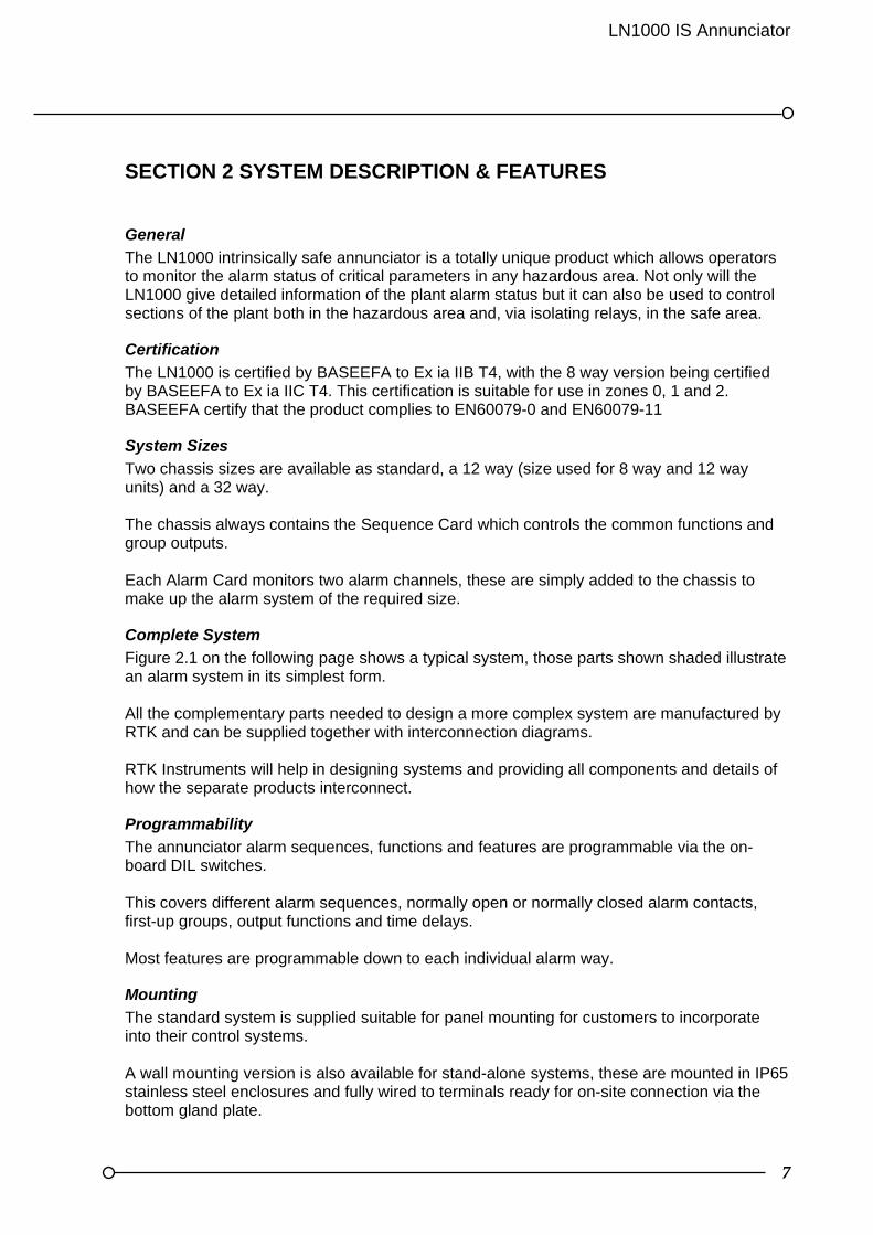
SECTION 2 SYSTEM DESCRIPTION & FEATURES
General
The LN1000 intrinsically safe annunciator is a totally unique product which allows operators to monitor the alarm status of critical parameters in any hazardous area. Not only will the LN1000 give detailed information of the plant alarm status but it can also be used to control sections of the plant both in the hazardous area and, via isolating relays, in the safe area.
Certification
The LN1000 is certified by BASEEFA to Ex ia IIB T4, with the 8 way version being certified by BASEEFA to Ex ia IIC T4. This certification is suitable for use in zones 0, 1 and 2. BASEEFA certify that the product complies to EN60079-0 and EN60079-11
System Sizes
Two chassis sizes are available as standard, a 12 way (size used for 8 way and 12 way units) and a 32 way. The chassis always contains the Sequence Card which controls the common functions and group outputs. Each Alarm Card monitors two alarm channels, these are simply added to the chassis to make up the alarm system of the required size.
Complete System
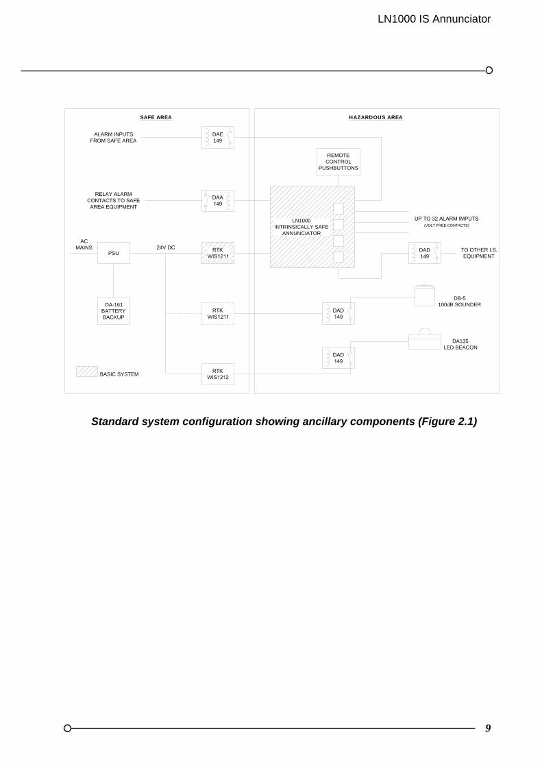
Figure 2.1 on the following page shows a typical system, those parts shown shaded illustrate an alarm system in its simplest form. All the complementary parts needed to design a more complex system are manufactured by RTK and can be supplied together with interconnection diagrams. RTK Instruments will help in designing systems and providing all components and details of how the separate products interconnect.
Programmability
The annunciator alarm sequences, functions and features are programmable via the on-board DIL switches. This covers different alarm sequences, normally open or normally closed alarm contacts, first-up groups, output functions and time delays. Most features are programmable down to each individual alarm way.
Mounting
The standard system is supplied suitable for panel mounting for customers to incorporate into their control systems. A wall mounting version is also available for stand-alone systems, these are mounted in IP65 stainless steel enclosures and fully wired to terminals ready for on-site connection via the bottom gland plate.
8
Servicing
As the LN1000 is certified as intrinsically safe, live inspection and maintenance procedures can be carried out at any time. All configuration and maintenance is carried out from the front by simply removing the front fascia and withdrawing the cards.
Lightweight
Being constructed from stainless steel and polyurethane mouldings make the LN1000 extremely lightweight in comparison to conventional flameproof and Type 'N' systems. This gives great benefits when space and payload are critical factors, especially offshore.
Group Outputs
A number of outputs are available as standard to drive external audibles and control other parts of the plant in the advent of certain alarms occurring. These outputs are programmable to operate in many different ways.
Inputs
The alarm inputs are normally situated in the hazardous area but can also be connected to the LN1000 from the safe area if connected via IS Relays (Type DA-149). The other inputs such as "alarm inhibit" and pushbuttons should all be local to the LN1000. Terminals are available as standard to fit external pushbuttons if required and the integral pushbuttons on the fascia can be disabled.
LN1000 IS Annunciator
9
Standard system configuration showing ancillary components (Figure 2.1)
DAE149
DAD149
PSU
DA-161BATTERYBACKUP
REMOTECONTROL
PUSHBUTTONS
DA135LED BEACON
DB-5100dB SOUNDER
TO OTHER I.S.EQUIPMENT
ALARM INPUTSFROM SAFE AREA
ACMAINS 24V DC
LN1000INTRINSICALLY SAFE
ANNUNCIATOR
BASIC SYSTEM
SAFE AREA HAZARDOUS AREA

10
SECTION 3 INPUTS & OUTPUTS
Terminations and interconnections
All connections to the LN1000 Annunciator are via rear mounted screw terminals. These terminals are suitable for cables up to 2.5mm². In the wall mounted versions the input and output terminals are wired to a row of 2.5mm²terminals on the backplane. The Sequence Card and the Alarm Cards are all interconnected by a common backplane. This backplane is used to supply power to the Alarm Cards, synchronise the flashing of the LED’s, ascertain the first-up alarm in any sequence, connect the pushbutton controls and provide a drive signal to the local horn, the external sounder outputs and all group outputs.
LN1000-AC Alarm Card
The Alarm Card monitors two alarm channels and each channel has the following inputs and outputs:
ALARM INPUT: CONNECTED TO THE VOLT-FREE ALARM CONTACTS
INHIBIT INPUTS: Connected To Volt-Free Contacts To Inhibit That Alarm Channel
GROUP A OUTPUT: Configurable To Follow The Alarm Logic Or The Field Contact
GROUP B OUTPUT: Configurable To Follow The Alarm Logic Or The Audible
LN1000-SC Sequence Card
Each system will have a Sequence Card which monitors and controls the common functions as follows:- PUSHBUTTON INPUTS:
FOR TEST, ACKNOWLEDGE, RESET AND SILENCE PUSHBUTTONS
HORN OUTPUT: Not Used
EXT SOUND: This Output Is Used To Drive An Is Relay, Which In Turn Will Switch External Higher Level Audible Devices.
B1 OUTPUT: Configurable To Follow The Alarm Logic Or Field Contacts
B2 OUTPUT: Reflash Output Gives A One Second Pulse On New Alarms
LN1000 IS Annunciator
11
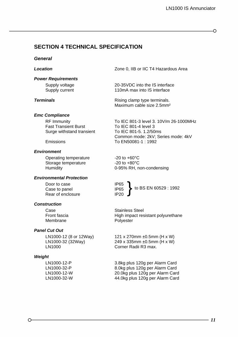
SECTION 4 TECHNICAL SPECIFICATION General Location Zone 0, IIB or IIC T4 Hazardous Area
Power Requirements
Supply voltage 20-35VDC into the IS interface Supply current 110mA max into IS interface Terminals Rising clamp type terminals. Maximum cable size 2.5mm²
Emc Compliance
RF Immunity To IEC 801-3 level 3. 10V/m 26-1000MHz Fast Transient Burst To IEC 801-4 level 3 Surge withstand transient To IEC 801-5. 1.2/50ms Common mode: 2kV; Series mode: 4kV Emissions To EN50081-1 : 1992
Environment
Operating temperature -20 to +60°C Storage temperature -20 to +80°C Humidity 0-95% RH, non-condensing
Environmental Protection
Door to case IP65 Case to panel IP65 Rear of enclosure IP20
Construction
Case Stainless Steel Front fascia High impact resistant polyurethane Membrane Polyester
Panel Cut Out
LN1000-12 (8 or 12Way) 121 x 270mm ±0.5mm (H x W) LN1000-32 (32Way) 249 x 335mm ±0.5mm (H x W) LN1000 Corner Radii R3 max.
Weight
LN1000-12-P 3.8kg plus 120g per Alarm Card LN1000-32-P 8.0kg plus 120g per Alarm Card LN1000-12-W 20.0kg plus 120g per Alarm Card LN1000-32-W 44.0kg plus 120g per Alarm Card
} to BS EN 60529 : 1992
12
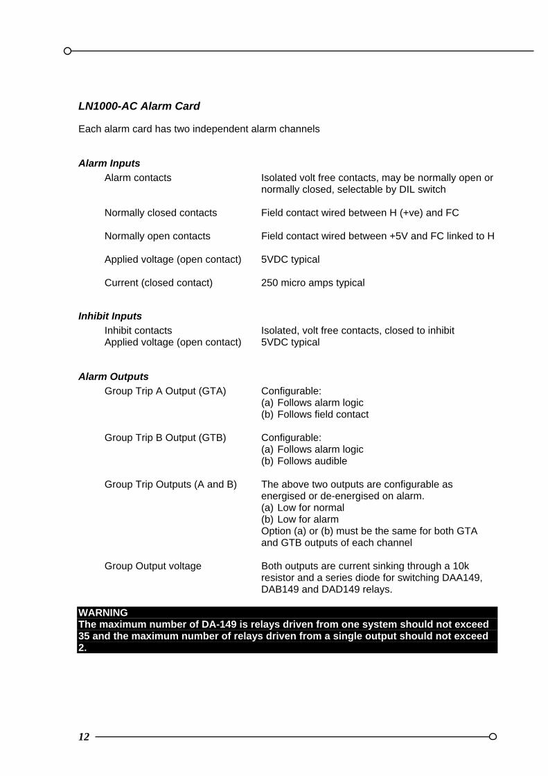
LN1000-AC Alarm Card Each alarm card has two independent alarm channels
Alarm Inputs
Alarm contacts Isolated volt free contacts, may be normally open or normally closed, selectable by DIL switch Normally closed contacts Field contact wired between H (+ve) and FC Normally open contacts Field contact wired between +5V and FC linked to H Applied voltage (open contact) 5VDC typical Current (closed contact) 250 micro amps typical
Inhibit Inputs
Inhibit contacts Isolated, volt free contacts, closed to inhibit Applied voltage (open contact) 5VDC typical
Alarm Outputs
Group Trip A Output (GTA) Configurable: (a) Follows alarm logic (b) Follows field contact Group Trip B Output (GTB) Configurable: (a) Follows alarm logic (b) Follows audible Group Trip Outputs (A and B) The above two outputs are configurable as energised or de-energised on alarm. (a) Low for normal (b) Low for alarm
Option (a) or (b) must be the same for both GTA and GTB outputs of each channel
Group Output voltage Both outputs are current sinking through a 10k resistor and a series diode for switching DAA149, DAB149 and DAD149 relays. WARNING The maximum number of DA-149 is relays driven from one system should not exceed 35 and the maximum number of relays driven from a single output should not exceed 2.
LN1000 IS Annunciator
13
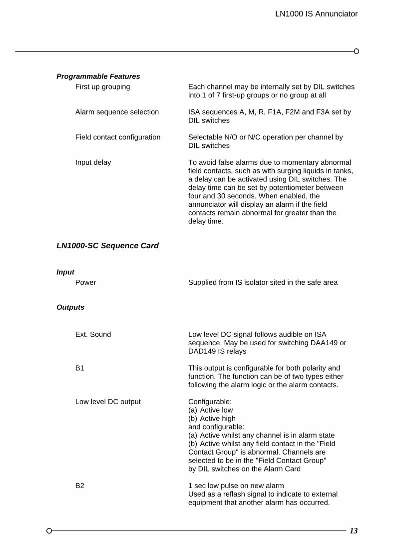
Programmable Features
First up grouping Each channel may be internally set by DIL switches into 1 of 7 first-up groups or no group at all Alarm sequence selection ISA sequences A, M, R, F1A, F2M and F3A set by DIL switches Field contact configuration Selectable N/O or N/C operation per channel by DIL switches Input delay To avoid false alarms due to momentary abnormal
field contacts, such as with surging liquids in tanks, a delay can be activated using DIL switches. The delay time can be set by potentiometer between four and 30 seconds. When enabled, the annunciator will display an alarm if the field contacts remain abnormal for greater than the delay time.
LN1000-SC Sequence Card
Input
Power Supplied from IS isolator sited in the safe area
Outputs
Ext. Sound Low level DC signal follows audible on ISA sequence. May be used for switching DAA149 or DAD149 IS relays B1 This output is configurable for both polarity and function. The function can be of two types either following the alarm logic or the alarm contacts. Low level DC output Configurable: (a) Active low (b) Active high and configurable: (a) Active whilst any channel is in alarm state (b) Active whilst any field contact in the "Field Contact Group" is abnormal. Channels are selected to be in the "Field Contact Group" by DIL switches on the Alarm Card B2 1 sec low pulse on new alarm Used as a reflash signal to indicate to external equipment that another alarm has occurred.

14
Push Buttons SILENCE [S] Operates on the external sounder output. The visual
display is not affected. ACKNOWLEDGE [A] Will stop the LED/LCD’s flashing and silence the audible. If a new alarm occurs on an already acknowledged system the audible will sound and the new alarm will flash. For full details refer to the sequence table relating to the alarm sequence selected. RESET [R] Will only operate after the alarm has been acknowledged and the plant condition has returned to normal. For full details refer to the sequence table relating to the alarm sequence selected. TEST [T] Illuminates all LED’s and all segments of LCD's on every alarm channel irrespective of alarm status. Will also drive the local horn and the external sounder. This function operates as long as the pushbutton is pressed. This function will not change the alarm state. SYSTEM TEST [S & T] Pressing and holding Silence and Test buttons for 4 seconds will cause the LN1000 to enter a test routine. Each channel is put into the highest state of alarm and latched in, it is then necessary to operate the Acknowledge and Reset pushbuttons to clear the alarms.
This test will also operate both the local and external sounders and the two common outputs B1 and B2
Other Features INTERNAL Internal push-buttons can be disabled by a jumper link EXTERNAL Terminals provided for optional external normally open pushbuttons OPTIONS Horn re-sound delay after silence. Adjustable on
Sequence Card between 0.5 to 15 minutes or infinite silence

LN1000 IS Annunciator
15
SECTION 5 MECHANICAL DETAILS
Alarm Chassis
The annunciator consists of a stainless steel case with integral card rails. The LN1000-12 is a single level unit, fitted with a LN1000-SC Sequence Card and up to six LN1000-AC Alarm Cards. The LN1000-32 is a double level unit, fitted with up to eight LN1000-AC Alarm Cards on the upper level, with an additional eight LN1000-AC Alarm Cards and a LN1000-SC Sequence Card on the lower level. The cards slide into the card rails and push into the connector mounted on the backplane. Each card is polarised to prevent incorrect assembly and are simple to remove and replace without the aid of specialised tools.
Fascia Panel The fascia panel is high impact resistant polyurethane, with a printed polyester membrane including transparent windows to view the legends and displays. The internal pushbuttons are attached to the rear of the fascia connected by a ribbon cable to the Sequence Card. The fascia is removed by unfastening the retained screws, and lifting the front panel down until it is held on the retaining straps
Alarm Cards
Each two-channel alarm card is fitted with an LED and a Liquid Crystal Display (LCD) for each channel. The LED follows the normal alarm sequence and the LCD indicates the sequence, field contact status, first-up and inhibit state of the alarm channel. To identify each alarm way when the system is in use traffolyte legends are used, these are located in the front panel above the upper channel and below the lower channel.
Sequence Card
The Sequence Card assembly contains the pushbuttons for controlling the stages in the alarm sequence and system outputs to control external audible alarms and other related control equipment.
Panel Mounting
The standard annunciator enclosure is designed for panel mounting. The fascia and the case to panel seal are protected to IP65. The unit is supplied with a rear cable housing to aid installation. This is removable to facilitate drilling and for mounting the enclosure. It is recommended that annunciators are installed in dry locations protected from corrosive atmospheres or direct sunlight

16
Wall Mounting
If the requirement is for a stand-alone wall mounting alarm system this can be supplied with the wall mounted variant. In this version the IS Annunciator is mounted in a stainless steel enclosure with the terminals wired and loomed around the hinge to a row of 2.5mm² terminals ready for external connection via the bottom gland plate.
Channel numbering
The channels are numbered starting from the Sequence Card towards the left. With two alarm channels on each card the lowest channel number is always the upper channel.
LN1000 IS Annunciator
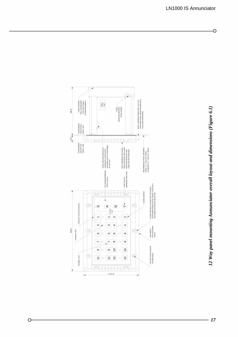
17
12
Way
pan
el m
oun
tin
g A
nn
un
ciat
or o
vera
ll la
you
t an
d di
men
sion
s (F
igu
re 6
.1)
1 7 0 .0
SY
ST
EM
TE
ST
PA
NE
L M
OU
NT
ING
BR
AC
KE
TS
AS
SE
MB
LED
IN
FR
OM
RE
AR
.
EN
SU
RIN
G H
OO
K IS
PO
SIT
ION
ED
IN T
HE
SLO
T.
31
9.0
CH
AN
NE
L LC
D's
PR
OD
UC
T C
ER
TIF
ICA
TIO
N N
o.
CH
AN
NE
L L
ED
's
911 11
9
S1
35
7
35
71
AP
OL
YE
ST
ER
ME
MB
RA
NE
FR
ON
T F
AS
CIA
191
.027
.0
EN
VIR
ON
ME
NT
PR
OT
EC
TIO
N
FR
ON
T -
IP65
.
EN
VIR
ON
ME
NT
PR
OT
EC
TIO
N
RE
AR
- IP
20.
CA
BLE
HO
US
ING
:
DR
ILL
AS
RE
QU
IRE
D
FO
R F
IEL
D C
AB
LE -
GLA
ND
S/G
RO
MM
ET
S.
SE
RIA
L
NU
MB
ER
LA
BE
L
UN
IT A
SS
EM
BL
ED
IN
TO
PA
NE
L
FR
OM
TH
E F
RO
NT
WIT
H P
AN
EL
MO
UN
TIN
G B
RA
CK
ET
S A
ND
CA
BLE
HO
US
ING
RE
MO
VE
D.
RE
CO
MM
EN
DE
D P
AN
EL
TH
ICK
NE
SS
ST
EE
L: 1
.6 -
4.0
mm
(16
- 8
SW
G).
AL
UM
INIU
M:
2.0
- 4
.0m
m (
14 -
8S
WG
).
1210
1210
4 O
FF
TA
CT
ILE
ME
MB
RA
NE
SW
ITC
HE
S8
46
2T
46
8R
2
M4
CA
PT
IVA
TE
D S
CR
EW
S
WIT
HIN
FA
SC
IA
GA
SK
ET
BE
TW
EE
N T
HE
BO
X A
ND
TH
E F
AS
CIA
(PO
SIT
ION
ED
IN
SID
E F
AS
CIA
), N
EE
DS
TO
BE
FU
LLY
TIG
HT
EN
ED
TO
AC
HIE
VE
IP65
RA
TIN
G.
HIG
H IM
PA
CT
PO
LYU
RE
TH
AN
E
FA
SC
IA
AL
AR
M L
EG
EN
DS
NO
TE
: C
OM
PR
ES
S F
RO
NT
SE
AL
FU
LLY
BY
TIG
HT
EN
ING
PA
NE
L M
OU
NT
ING
BR
AC
KE
TS
TO
AC
HIE
VE
IP
65 R
AT
ING
.PA
NE
L
MO
UN
TIN
G B
RA
CK
ET
FIX
ING
SC
RE
W
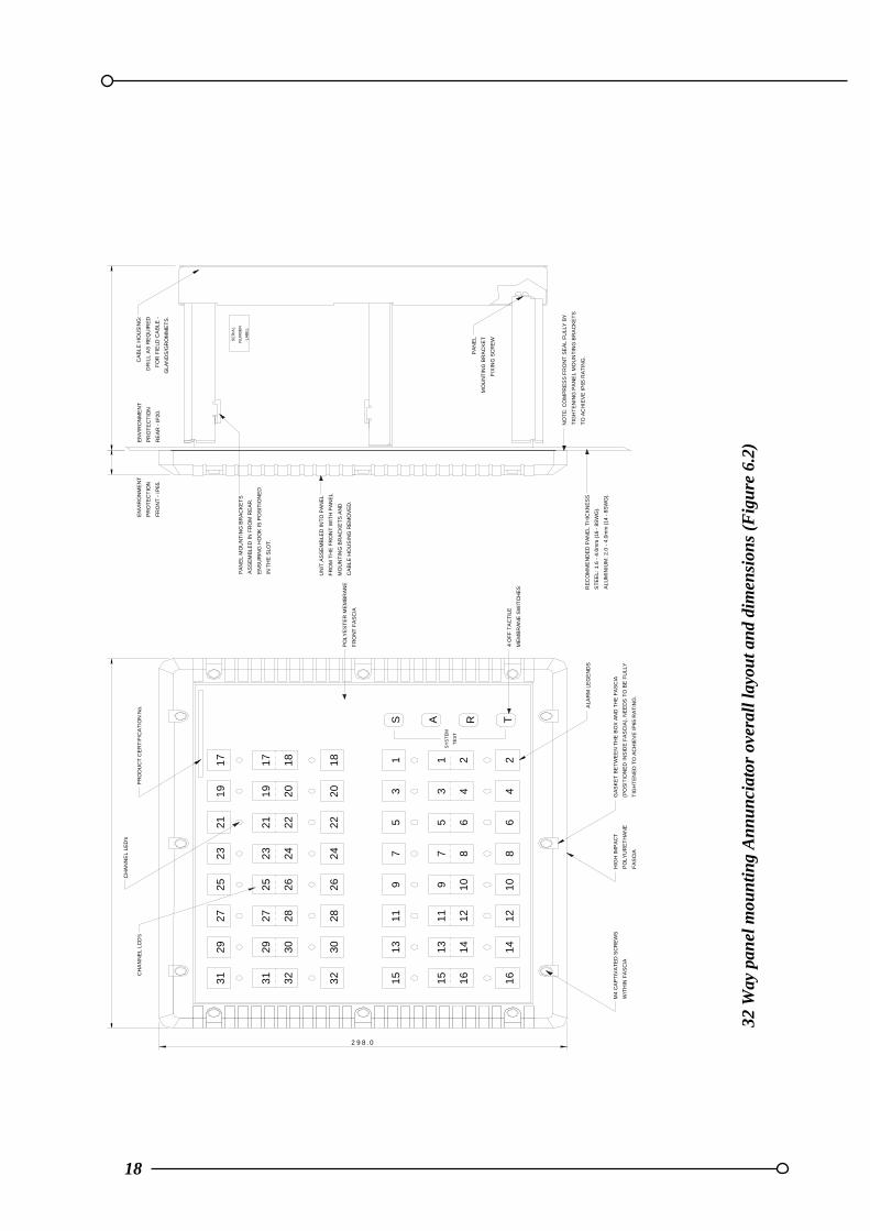
18
32 W
ay p
anel
mou
nti
ng
An
nu
nci
ator
ove
rall
layo
ut a
nd
dim
ensi
ons
(Fig
ure
6.2
)
ALA
RM
LE
GE
ND
S
GA
SK
ET
BE
TW
EE
N T
HE
BO
X A
ND
TH
E F
AS
CIA
(PO
SIT
ION
ED
IN
SID
E F
AS
CIA
), N
EE
DS
TO
BE
FU
LLY
TIG
HT
EN
ED
TO
AC
HIE
VE
IP65
RA
TIN
G.
2 9 8 .0
2827 27
CH
AN
NE
L LC
D's
32
31
31
29 29 30
CH
AN
NE
L L
ED
's
25
25
26
23
21
24
23
2221
PR
OD
UC
T C
ER
TIF
ICA
TIO
N N
o.
19
17
20
19
18
17
1211 121128
16
14
15
15
32
1330 13
16
14
M4
CA
PT
IVA
TE
D S
CR
EW
S
WIT
HIN
FA
SC
IA
68
10926 9
5724
22
75
10
86
SY
ST
EM
TE
ST
42
31
20
18
31
S A
42
R T
HIG
H IM
PA
CT
PO
LYU
RE
TH
AN
E
FA
SC
IA
UN
IT A
SS
EM
BLE
D IN
TO
PA
NE
L
FR
OM
TH
E F
RO
NT
WIT
H P
AN
EL
MO
UN
TIN
G B
RA
CK
ET
S A
ND
CA
BLE
HO
US
ING
RE
MO
VE
D.
EN
VIR
ON
ME
NT
PR
OT
EC
TIO
N
RE
AR
- IP
20.
PA
NE
L M
OU
NT
ING
BR
AC
KE
TS
AS
SE
MB
LED
IN
FR
OM
RE
AR
.
EN
SU
RIN
G H
OO
K I
S P
OS
ITIO
NE
D
IN T
HE
SLO
T.
EN
VIR
ON
ME
NT
PR
OT
EC
TIO
N
FR
ON
T -
IP6
5.
CA
BLE
HO
US
ING
:
DR
ILL
AS
RE
QU
IRE
D
FO
R F
IELD
CA
BLE
-
GLA
ND
S/G
RO
MM
ET
S.
SE
RIA
L
NU
MB
ER
LA
BE
L
RE
CO
MM
EN
DE
D P
AN
EL
TH
ICK
NE
SS
ST
EE
L: 1
.6 -
4.0
mm
(16
- 8
SW
G).
ALU
MIN
IUM
: 2
.0 -
4.0
mm
(14
- 8
SW
G).
PO
LY
ES
TE
R M
EM
BR
AN
E
FR
ON
T F
AS
CIA
4 O
FF
TA
CT
ILE
ME
MB
RA
NE
SW
ITC
HE
S
PA
NE
L
MO
UN
TIN
G B
RA
CK
ET
FIX
ING
SC
RE
W
NO
TE
: C
OM
PR
ES
S F
RO
NT
SE
AL
FU
LLY
BY
TIG
HT
EN
ING
PA
NE
L M
OU
NT
ING
BR
AC
KE
TS
TO
AC
HIE
VE
IP65
RA
TIN
G.
LN1000 IS Annunciator
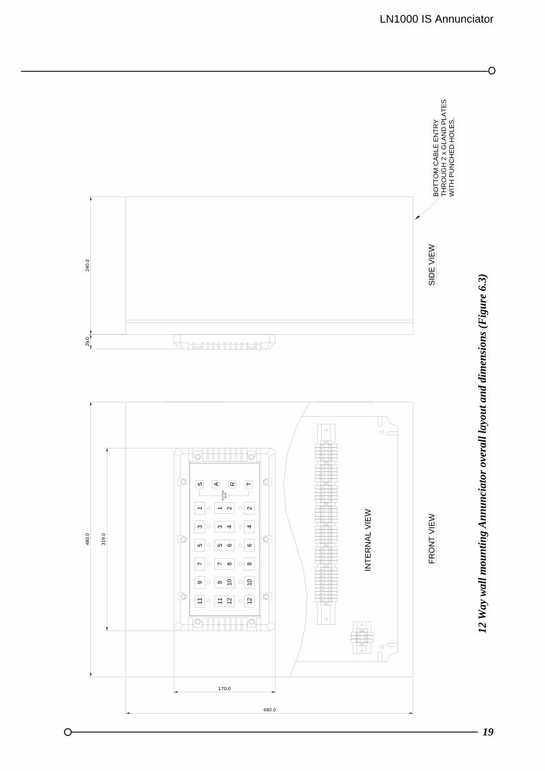
19
12 W
ay w
all m
oun
tin
g A
nn
un
ciat
or o
vera
ll la
you
t an
d di
men
sion
s (F
igu
re 6
.3)
480.0
240.
0
SID
E V
IEW
26.
0
319
.0
480.
0
RA
11 11 12 12
170.0
9 9
57 7
5
1010
688
6S
YS
TE
M
3 3
1 1
44
22T
ES
T
INT
ER
NA
L V
IEW
FR
ON
T V
IEW
S T
BO
TT
OM
CA
BLE
EN
TR
Y
WIT
H P
UN
CH
ED
HO
LES
.T
HR
OU
GH
2 x
GLA
ND
PLA
TE
S

20
32 W
ay w
all m
oun
tin
g A
nn
un
ciat
or o
vera
ll la
you
t an
d di
men
sion
s (F
igu
re 6
.4)
68
10T
2
R
25.0
==
100.0
INT
ER
NA
L V
IEW
720.
0
720.0
240
.0
19
21
17
17
20
22
2426
18
11 1211 12
141
6
15
13
15
13 141
6
24
108
6
79
35
79
35
S1
A1
SY
ST
EM
TE
ST
4
WIT
H P
UN
CH
ED
HO
LES
2 x
GLA
ND
PLA
TE
SB
OT
TO
M C
AB
LE E
NT
RY
298.0
384.
0
282727 2830
32
31
29
31
29 303
2
18
20
22
2426
2325
19
21
2325

LN1000 IS Annunciator
21
SECTION 6 ALARM SEQUENCES
Summary
From the sequence tables shown in the following pages, it will be evident that an alarm occurring causes a flashing visual indication with audible and optional relay drive. The following pushbutton inputs summarise the user controls TEST may be operated at any time and operates on the visual indication and the audible output, turning on all LED’s, LCD’s and the audible. These will remain on for as long as the button is pressed. ACKNOWLEDGE stops the flashing and audible. If a new alarm occurs on an already acknowledged system, the horn will sound and the new alarm will flash. RESET operates only if the visual is steady and plant conditions have returned to normal. The relay drive is normally only terminated when the reset operates. SILENCE is used only to silence the audible.
First-up sequence
When a group of alarms is initiated, it is often important to know which of them was the first to occur. This is achieved by both flashing the first-up alarm in a different manner compared to the subsequent alarms and also showing the 'F' in the LCD display. Three different first-up sequences are available F1, F2 and F3 as detailed below and in the following sequence tables. First-up operation should be used with care with the auto-reset sequence as momentary alarms can cause ambiguity. F1 In this mode subsequent alarms appear in the acknowledged state, hence they do not
flash. The audible device does not operate when subsequent alarms occur, unless still operating from the first alarm. The acknowledge pushbutton will reset the first-up indication.
F2 In this mode all subsequent alarms do not flash, they will however operate the audible device. The acknowledge pushbutton will reset the first-up indication. F3 Additional types of flashing are added so that the first-up alarm can still be identified
when the annunciator has been acknowledged. The acknowledge pushbutton does not reset the first-up indication this is cleared using the reset pushbutton.
22
Auto reset sequence
In this mode, the contacts returning to normal on an acknowledged alarm causes that alarm to reset. If the alarm contact returns to normal prior to being acknowledged, the alarm will reset immediately on Acknowledge.
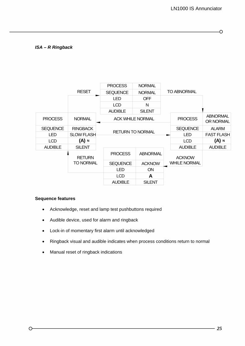
Ringback sequence
This mode is used to indicate to operators that the alarm contact has returned back to its normal state hence avoiding having to continually press the reset pushbutton, to see if the plant contacts have returned to their non alarm state. TO CHANGE FROM ONE SEQUENCE TO ANOTHER SEE THE DIL SWITCH SETTINGS DETAILS IN THE SECTION 14: SYSTEM CONFIGURATION AND PROGRAMMING
LN1000 IS Annunciator
23
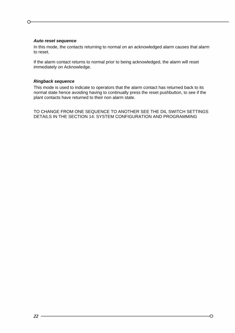
SECTION 7 SEQUENCE TABLES Example Sequence Tables Each alarm channel can be configured to suit the operating sequence required, as listed in the ISA publication "Annunciator sequences and specifications" S18.1 1979. Systems can be configured with different features on different alarm ways. Remember after changing a DIL switch setting it is essential that the power is turned off and on again to register the new settings. The following tables show the most commonly used examples.
ISA – M Manual Reset
PROCESS
SEQUENCE
LED
LCD
ABNORMALOR NORMAL
ALARMFLASHING
(A)
SEQUENCE
PROCESS
OFFLED
LCD N
NORMAL
NORMAL
ACKNOWLEDGE
RESETWHILE NORMAL
TO ABNORMAL
LCD
LED
SEQUENCE
PROCESSABNORMALOR NORMAL
ONACKNOW
AUDIBLE SILENT
AUDIBLE AUDIBLE
N
AUDIBLE SILENTA N
Sequence features
Acknowledge, reset and lamp test pushbuttons required
Alarm audible device
Lock-in of momentary alarms until acknowledged
The audible device is silenced and flashing stops when acknowledged
Manual reset of acknowledged alarms only after process conditions return to normal
24
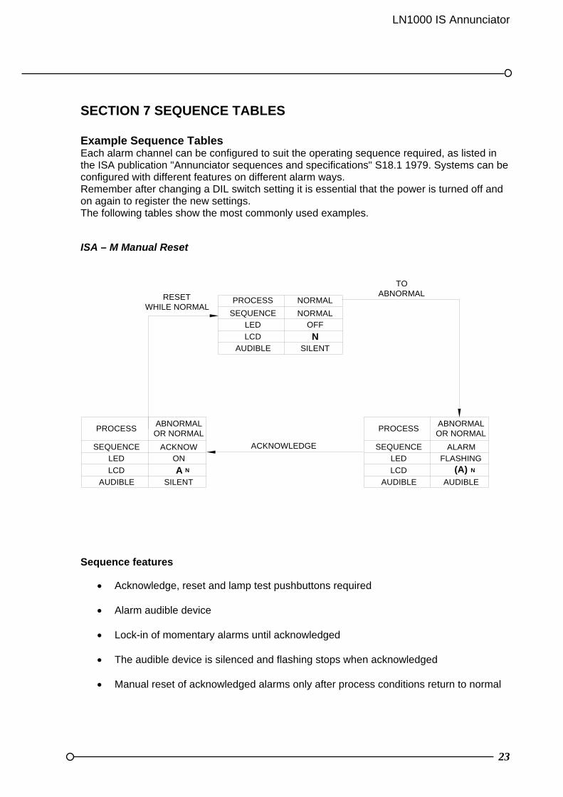
ISA – A Auto Reset
PROCESS
SEQUENCE
LED
LCD
ABNORMALOR NORMAL
ALARMFLASHING
SEQUENCE
PROCESS
OFFLED
LCD
NORMAL
NORMAL
ACKNOWLEDGEWHILE ABNORMAL
RETURN TO NORMAL
TO ABNORMAL
ACKNOWLWDGEWHILE NORMAL
LCD
LED
SEQUENCE
PROCESSABNORMALOR NORMAL
ONACKNOW
AUDIBLE SILENT
AUDIBLE AUDIBLE
N
AUDIBLE SILENT
N
A (A)
Sequence features Acknowledge and lamp test pushbuttons required Alarm audible device Lock-in of momentary alarms until acknowledged The audible device is silenced and flashing stops when acknowledged Automatic reset of acknowledged alarms when process conditions return to normal
LN1000 IS Annunciator
25
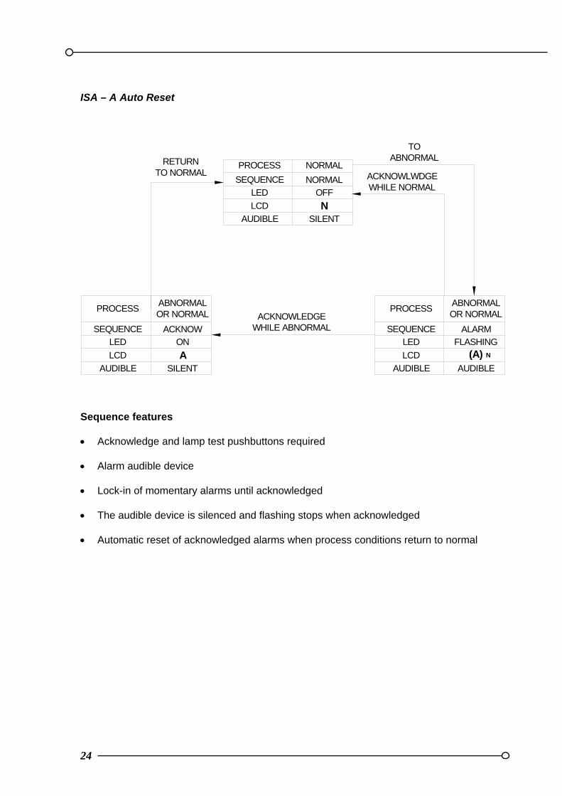
ISA – R Ringback
PROCESS
SEQUENCE
LED
LCD
ABNORMAL OR NORMAL
ALARMFAST FLASH
(A)
SEQUENCE
PROCESS
OFFLED
LCD N
NORMAL
NORMAL
LCD
LED
SEQUENCE
PROCESS ABNORMAL
AON
ACKNOW
NORMALPROCESS
LED
LCD
SEQUENCE
SLOW FLASHRINGBACK
RETURN TO NORMAL
TO ABNORMALRESET
RETURN TO NORMAL
ACKNOWWHILE NORMAL
AUDIBLE SILENT
AUDIBLE AUDIBLE
N
SILENTAUDIBLE
AUDIBLE
(A) N
ACK WHILE NORMAL
SILENT
Sequence features
Acknowledge, reset and lamp test pushbuttons required
Audible device, used for alarm and ringback
Lock-in of momentary first alarm until acknowledged
Ringback visual and audible indicates when process conditions return to normal
Manual reset of ringback indications
26
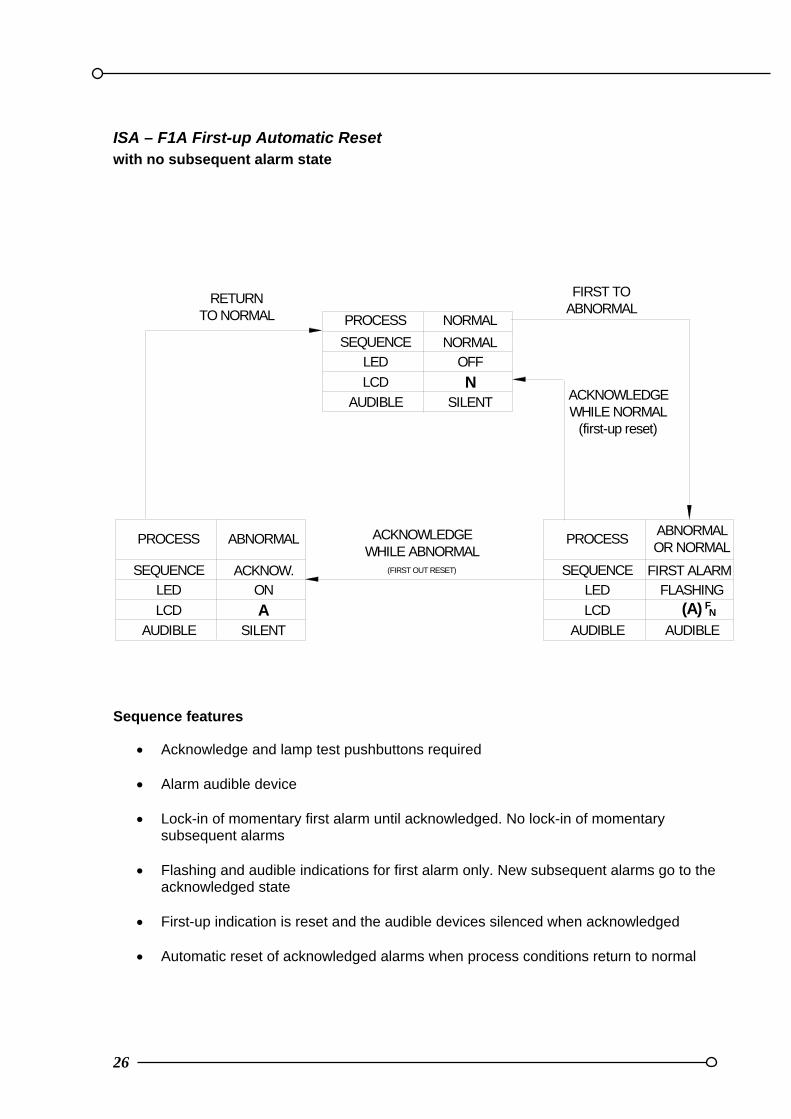
ISA – F1A First-up Automatic Reset with no subsequent alarm state
PROCESS
SEQUENCE
ABNORMALOR NORMAL
FIRST ALARMFLASHING
SEQUENCE
PROCESS
OFF
NORMAL
NORMAL
ACKNOWLEDGEWHILE ABNORMAL
(FIRST OUT RESET)
RETURN TO NORMAL
FIRST TO ABNORMAL
SEQUENCE
PROCESS ABNORMAL
ACKNOW.
AUDIBLE SILENT
LED
LCD N
LED
AUDIBLE AUDIBLE
LCD (A) F N
AUDIBLE SILENT
LED
LCD AON
ACKNOWLEDGEWHILE NORMAL
(first-up reset)
Sequence features
Acknowledge and lamp test pushbuttons required
Alarm audible device
Lock-in of momentary first alarm until acknowledged. No lock-in of momentary subsequent alarms
Flashing and audible indications for first alarm only. New subsequent alarms go to the
acknowledged state
First-up indication is reset and the audible devices silenced when acknowledged
Automatic reset of acknowledged alarms when process conditions return to normal
LN1000 IS Annunciator
27
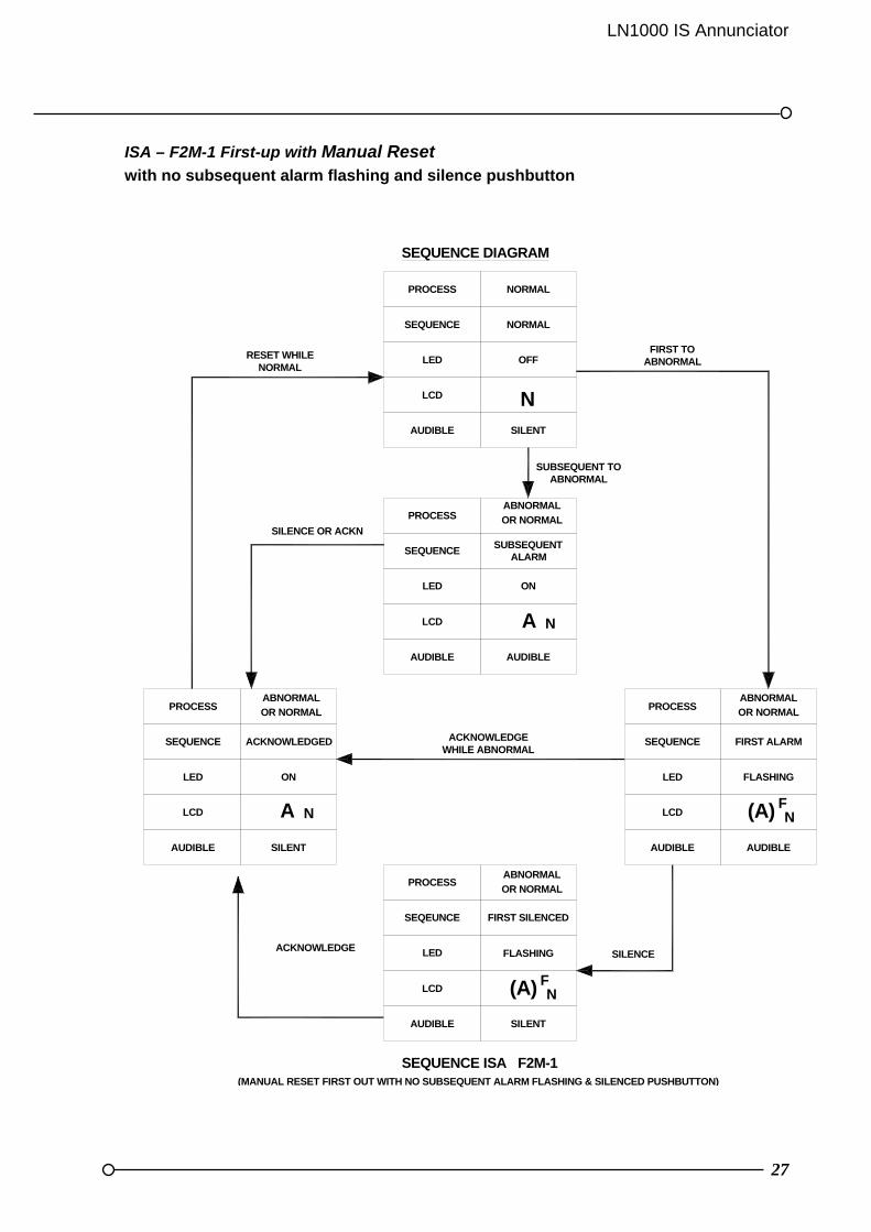
ISA – F2M-1 First-up with Manual Reset with no subsequent alarm flashing and silence pushbutton
PROCESS
LCD
LED
SEQUENCE
LED ON
FIRST ALARM
SEQUENCE ISA F2M-1(MANUAL RESET FIRST OUT WITH NO SUBSEQUENT ALARM FLASHING & SILENCED PUSHBUTTON)
AUDIBLE
ACKNOWLEDGE
LCD
SILENT
FLASHING SILENCE
ACKNOWLEDGE WHILE ABNORMAL
ACKNOWLEDGED
AUDIBLE
LCD
LED
SEQUENCE
PROCESS
FLASHING
ABNORMAL
SILENCE OR ACKN
PROCESS
SEQUENCE
RESET WHILENORMAL
AUDIBLE
LCD
SEQUENCE
LED
SUBSEQUENT TO ABNORMAL
SUBSEQUENTALARM
SILENT
OFF
NORMAL
FIRST TO ABNORMAL
SEQUENCE DIAGRAM
OR NORMAL
ABNORMAL
OR NORMAL
ABNORMAL
OR NORMAL
NORMALPROCESS
N
AUDIBLE AUDIBLE
(A) FN
PROCESSABNORMAL
OR NORMAL
SEQEUNCE FIRST SILENCED
LED
(A) FN
LCD A N
SILENTAUDIBLE
NA
AUDIBLE
ON
28
Sequence features
Mute, acknowledge reset and lamp test pushbuttons required
Alarm audible device
Lock-in of momentary first alarm until acknowledged.
Silence pushbutton to silence the audible device while retaining first-up flashing indication
Flashing indication for first alarm only. New subsequent alarms have the same visual
as acknowledged alarms
First-up indication is reset and the audible devices silenced when acknowledged
Manual reset of acknowledged alarms after process conditions return to normal
LN1000 IS Annunciator
29
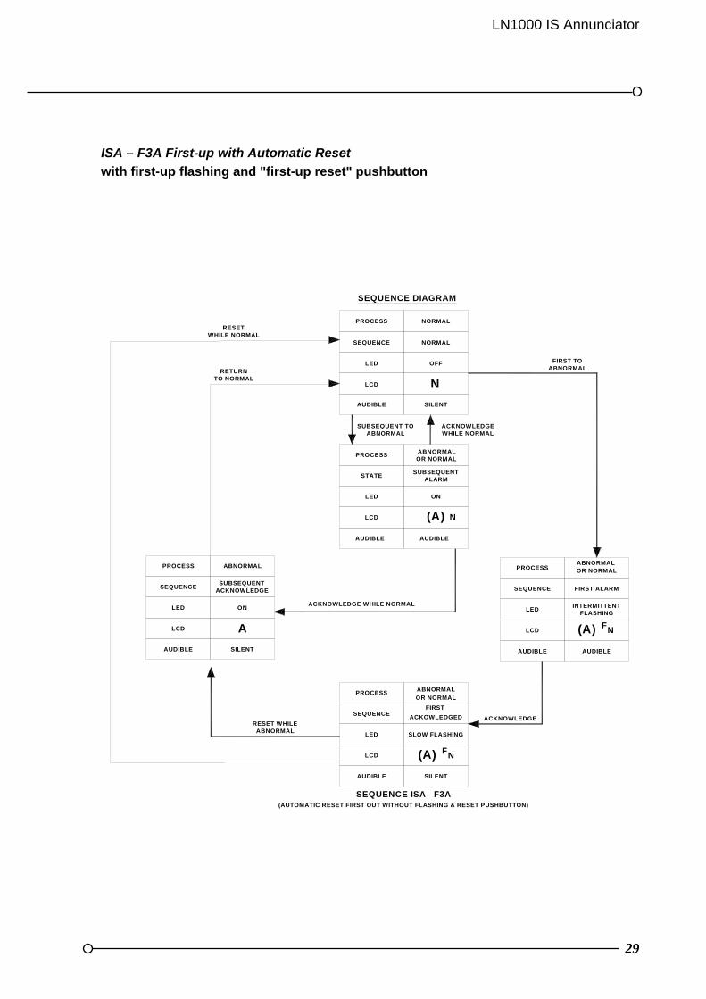
ISA – F3A First-up with Automatic Reset
with first-up flashing and "first-up reset" pushbutton
LCD
PROCESS
LED
SEQUENCE
SEQUENCE ISA F3A(AUTOMATIC RESET FIRST OUT WITHOUT FLASHING & RESET PUSHBUTTON)
LCD
LED
SEQUENCE
PROCESS
ACKNOWLEDGE
FIRST
SLOW FLASHING
ABNORMAL
LCD
INTERMITTENTFLASHING
FIRST ALARMSUBSEQUENT
ACKNOWLEDGE
ON
ABNORMAL
LED
LCD
PROCESS
STATE
SEQUENCE
LED
PROCESS
ON
SUBSEQUENTALARM
ABNORMAL
SEQUENCE DIAGRAM
RETURN TO NORMAL
ACKNOWLEDGE WHILE NORMAL
AUDIBLE
LED
SEQUENCE
FIRST TO ABNORMAL
SUBSEQUENT TO ABNORMAL
SILENT
OFF
NORMAL
ABNORMAL
ACKOWLEDGED
OR NORMAL
OR NORMAL
OR NORMAL
PROCESS NORMAL
LCD N
AUDIBLE AUDIBLE
(A) N
AUDIBLE AUDIBLE
(A) NF
AUDIBLE SILENT
F(A) N
SILENTAUDIBLE
A
RESETWHILE NORMAL
ACKNOWLEDGE WHILE NORMAL
RESET WHILE ABNORMAL

30
Sequence features
Acknowledge, first-up reset and lamp test pushbuttons required
Alarm audible device
Lock-in of momentary first alarm until acknowledged.
First-up flashing different from subsequent flashing.
First-up reset pushbutton to change the first-up visual indication to be the same as subsequent visual indication.
Automatic reset of acknowledged alarms when process conditions return to normal

LN1000 IS Annunciator
31
SECTION 8 MOUNTING
Panel mounting version
Refer to Figures 6.1 and 6.2 for panel cut-out dimensions and for details covered by the mounting procedure which follows:
1 Prepare the panel cut out to the dimensions shown in Figure 6.1 or 6.2 for the appropriate unit size
2 Remove rear cover, cable housing and all panel mounting clamps from the box
3 Slide the unit backwards through the cut out in the panel from the front until the front
flange gasket butts up to the panel
4 Attach all panel mounting brackets ensuring hooks are positioned into the slots provided in the box
5 Tighten panel mounting bracket screws evenly unit the box fascia flange is tight up
against the front of the panel
6 Drill the cable housing to suit glands/grommets to be used and re-fit onto box
7 Wire as required
8 Re-fit the rear cover Removal / fitting of Fascia Panel Antistatic precautions should be taken when the fascia is removed and when handling Sequence/Alarm Cards (see Appendix B for details)
Removal
1 Use the special socket provided for fastening/unfastening the fascia screws 2 Loosen fascia screws evenly until they are free. Note the screws are retained within
the fascia moulding itself
3 Holding either side of the fascia moulding, slide forwards off the alignment dowels positioned either side on the top of the box
4 Lower the top of the fascia towards you (down), positioning the bottom of the fascia
under the bottom flange on the box to act as a hinge until the two retaining straps hold the fascia in an open position
5 DO NOT LEAN OR REST HEAVY LOADS on the inside of the fascia
6 Full access to PCB's/alarm legends is now available

32
Re-fitting
1 Refitting is the reverse of the above section on the removal process. Ensure fascia straps and Pushbutton Board ribbon cable do not trap between fascia and box seal
2 Hold fascia in position while partly tightening fascia screws
3 Tighten fascia screws evenly to seal to the enclosure, some resistance will be felt due
to the compression of the seal gasket, do not over tighten.

LN1000 IS Annunciator
33
Removal / Replacement of Sequence and Alarm Cards
Antistatic precautions should be taken when the front fascia is removed and when handling Sequence/Alarm Cards (see Appendix B for details) Grip the card at the edge above and below the LCD/LED bracket, evenly pull the card so that it slides along the guide rails to remove it from the case. To replace a card slide it along the guide rails until it is firmly located in the two connectors mounted on the backplane. 12 Way Annunciator with the fascia removed (Figure 8.1)
SEQUENCE CARD
FRONT FASCIA LOCATION HOLES
+5v
ALARM 5ALARM 6 ALARM 4 ALARM 3 ALARM 2 ALARM 1
ALARM CARDS (6 MAX)
BOX - CABLE HOUSING - REAR COVERAND PANEL MOUNTING BRACKETSALL MANUFACTURED FROM STAINLESS STEEL.
FASCIA RETAINING STRAPSIN 2 PLACES.
METHOD FOR ADDING OR REMOVAL OF CARDS:
1) REMOVE POWER FROM UNIT.2) HOLD STRAPS ON EITHER SIDE OF CARDS AND PULL FIRMLY.3) FITMENT IS THE REVERSAL OF ABOVE.4) ENSURE CARDS ARE FULLY INSERTED BEFORE REFITTING FASCIA.5) ANTI-STATIC PRECAUTIONS MUST BE UNDERTAKEN AT ALL TIMES.

34
32 Way Annunciator with the fascia removed (Figure 8.2)
ALARM CARDS (6 MAX)
ALARM 8 ALARM 7 ALARM 6
ALARM 16 ALARM 15 ALARM 14
SEQUENCE CARD
FRONT FASCIA LOCATION HOLES
ALARM 5 ALARM 4 ALARM 3 ALARM 2 ALARM 1
ALARM 13 ALARM 12 ALARM 11 ALARM 10 ALARM 19
METHOD FOR ADDING OR REMOVAL OF CARDS:
1) REMOVE POWER FROM UNIT.2) HOLD STRAPS ON EITHER SIDE OF CARDS AND PULL FIRMLY.3) FITMENT IS THE REVERSAL OF ABOVE.4) ENSURE CARDS ARE FULLY INSERTED BEFORE REFITTING FASCIA.5) ANTI-STATIC PRECAUTIONS MUST BE UNDERTAKEN AT ALL TIMES.
BOX - CABLE HOUSING - REAR COVERAND PANEL MOUNTING BRACKETSALL MANUFACTURED FROM STAINLESS STEEL.
FASCIA RETAINING STRAPSIN 2 PLACES.
LN1000 IS Annunciator
35
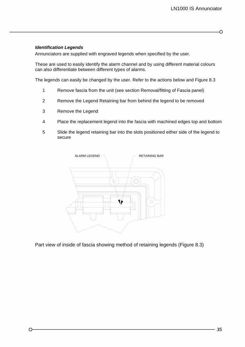
Identification Legends
Annunciators are supplied with engraved legends when specified by the user. These are used to easily identify the alarm channel and by using different material colours can also differentiate between different types of alarms. The legends can easily be changed by the user. Refer to the actions below and Figure 8.3
1 Remove fascia from the unit (see section Removal/fitting of Fascia panel) 2 Remove the Legend Retaining bar from behind the legend to be removed
3 Remove the Legend
4 Place the replacement legend into the fascia with machined edges top and bottom
5 Slide the legend retaining bar into the slots positioned either side of the legend to
secure Part view of inside of fascia showing method of retaining legends (Figure 8.3)
RETAINING BARALARM LEGEND

36
SECTION 9 FIELD WIRING
Certification
The LN1000 IS Annunciator system must be installed and wired in accordance with the requirements of the IS System certificate and IS codes of practice. This document should be read along with the associated equipment certificates and drawings before proceeding further. Copies of these drawings and certificates are available on request from RTK Instruments Ltd
General
All field wiring to the annunciator should use screened cable. The screening must be securely terminated using ring terminals on the studs provided. The removable cable housing should be drilled for user supplied gland fittings. Access to the annunciator terminals is achieved by removal of the rear cover on the cable housing. The terminal blocks form part of the edge connector for each card. All wiring must meet the Cable Parameter requirements detailed in Appendix A. The terminals are clearly marked on the backplane as to their function i.e. AL1, AL2 etc for the Alarm Cards and Sequence Card are marked as such. The individual terminals for each block are numbered 1 to 12. The terminal connectors are clipped into the backplane. These should not be removed from the backplane during wiring. Check the connectors are still correctly clipped into the backplane on completion of wiring.
Rear view of the 12 way annunciator showing the terminals (Figure 9.1)
1A
L 5
1
12
F.E
.C C
AR
D
SE
QU
EN
CE
CA
RD
J1 1 J2
12
1
12
12
J3 1
12
1J4 J5
12
1J6
12
1J7
1
1
AL
11
AL
21
AL
31
AL
41
12
J81
AL
61
CABLE HOUSING RETAINED BY 6 OFF M3 THUMB SCREWS.
ALL PANEL MOUNTING SCREWS ARE ACCESSIBLE WITH REAR PANEL REMOVED.SCREWS ARE CAPTIVE TO MOUNTING BRACKETS.
M4 CHASSIS EARTH STUD TERMINATIONS.
CONNECTOR TERMINALSSUITABLE FOR CONDUCTORS UP TO 5mm.

LN1000 IS Annunciator
37
Rea
r vi
ew o
f 32
way
an
nu
nci
ator
sh
owin
g th
e te
rmin
als
(Fig
ure
9.2
)
CA
BL
E H
OU
SIN
G R
ET
AIN
ED
BY
6 O
FF
M3
TH
UM
B S
CR
EW
S.
CO
NN
EC
TO
R T
ER
MIN
ALS
SU
ITA
BLE
FO
R
CO
ND
UC
TO
RS
UP
TO
5m
m.
ALL
PA
NE
L M
OU
NT
ING
SC
RE
WS
AR
E
AC
CE
SS
IBLE
WIT
H R
EA
R P
AN
EL
RE
MO
VE
D.
SC
RE
WS
AR
E C
AP
TIV
E T
O M
OU
NT
ING
BR
AC
KE
TS
.
M4
CH
AS
SIS
EA
RT
H S
TU
D
TE
RM
INA
TIO
NS
(B
OT
H S
IDE
S).
TO
P B
AC
KP
LAN
E
AS
SE
MB
LY
BO
TT
OM
BA
CK
PL
AN
E
AS
SE
MB
LY
SEQUENCE CARD
F.E.C CARD
AL 1
1 12
121
AL 2
AL 3
AL 4
AL 5
AL 6
1 12
1
1
1
1
1
12
12
12
12
12
J81
J7J6
J5J4
J3J2
J1
11
11
1
11
AL 71 12
J91
AL 81 12
J10
1
SEQUENCE CARD
F.E.C CARD
AL 1
1 12
121
AL 2
AL 3
AL 4
AL 5
AL 6
1 12
1
1
1
1
1
12
12
12
12
12
J81
J7J6
J5J4
J3J2
J1
11
11
1
11
AL 71 12
J91
AL 81 12
J10
1
38
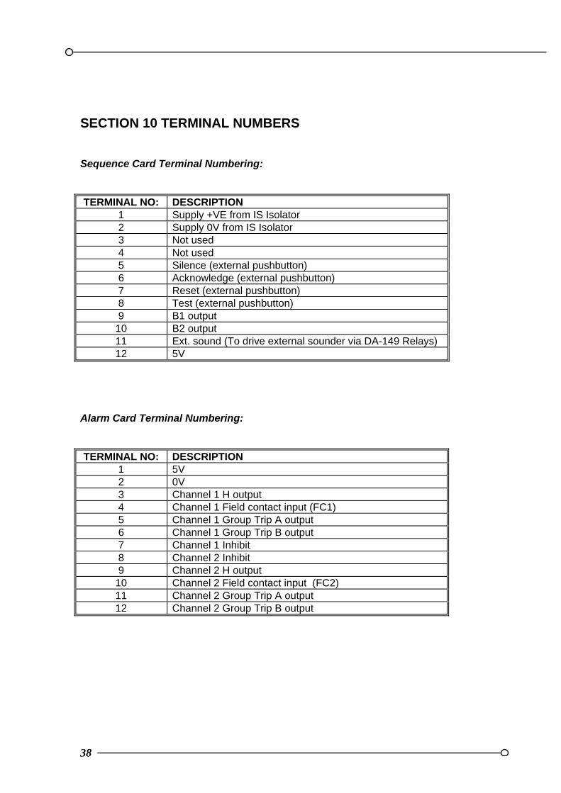
SECTION 10 TERMINAL NUMBERS
Sequence Card Terminal Numbering:
TERMINAL NO: DESCRIPTION 1 Supply +VE from IS Isolator 2 Supply 0V from IS Isolator 3 Not used 4 Not used 5 Silence (external pushbutton) 6 Acknowledge (external pushbutton) 7 Reset (external pushbutton) 8 Test (external pushbutton) 9 B1 output
10 B2 output 11 Ext. sound (To drive external sounder via DA-149 Relays) 12 5V
Alarm Card Terminal Numbering:
TERMINAL NO: DESCRIPTION 1 5V 2 0V 3 Channel 1 H output 4 Channel 1 Field contact input (FC1) 5 Channel 1 Group Trip A output 6 Channel 1 Group Trip B output 7 Channel 1 Inhibit 8 Channel 2 Inhibit 9 Channel 2 H output
10 Channel 2 Field contact input (FC2) 11 Channel 2 Group Trip A output 12 Channel 2 Group Trip B output
LN1000 IS Annunciator
39
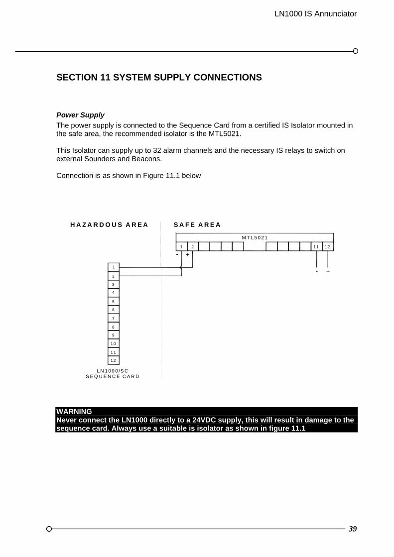
SECTION 11 SYSTEM SUPPLY CONNECTIONS
Power Supply
The power supply is connected to the Sequence Card from a certified IS Isolator mounted in the safe area, the recommended isolator is the MTL5021. This Isolator can supply up to 32 alarm channels and the necessary IS relays to switch on external Sounders and Beacons. Connection is as shown in Figure 11.1 below IS power supply connection (Figure 11.1) WARNING Never connect the LN1000 directly to a 24VDC supply, this will result in damage to the sequence card. Always use a suitable is isolator as shown in figure 11.1
1 2
1 1
1 0
9
8
7
6
5
4
3
2
1
S E Q U E N C E C A R D
H A Z A R D O U S A R E A S A F E A R E A
+-
+-
M T L 5 0 2 1
1 1 1 21 2
L N 1 0 0 0 /S C
40
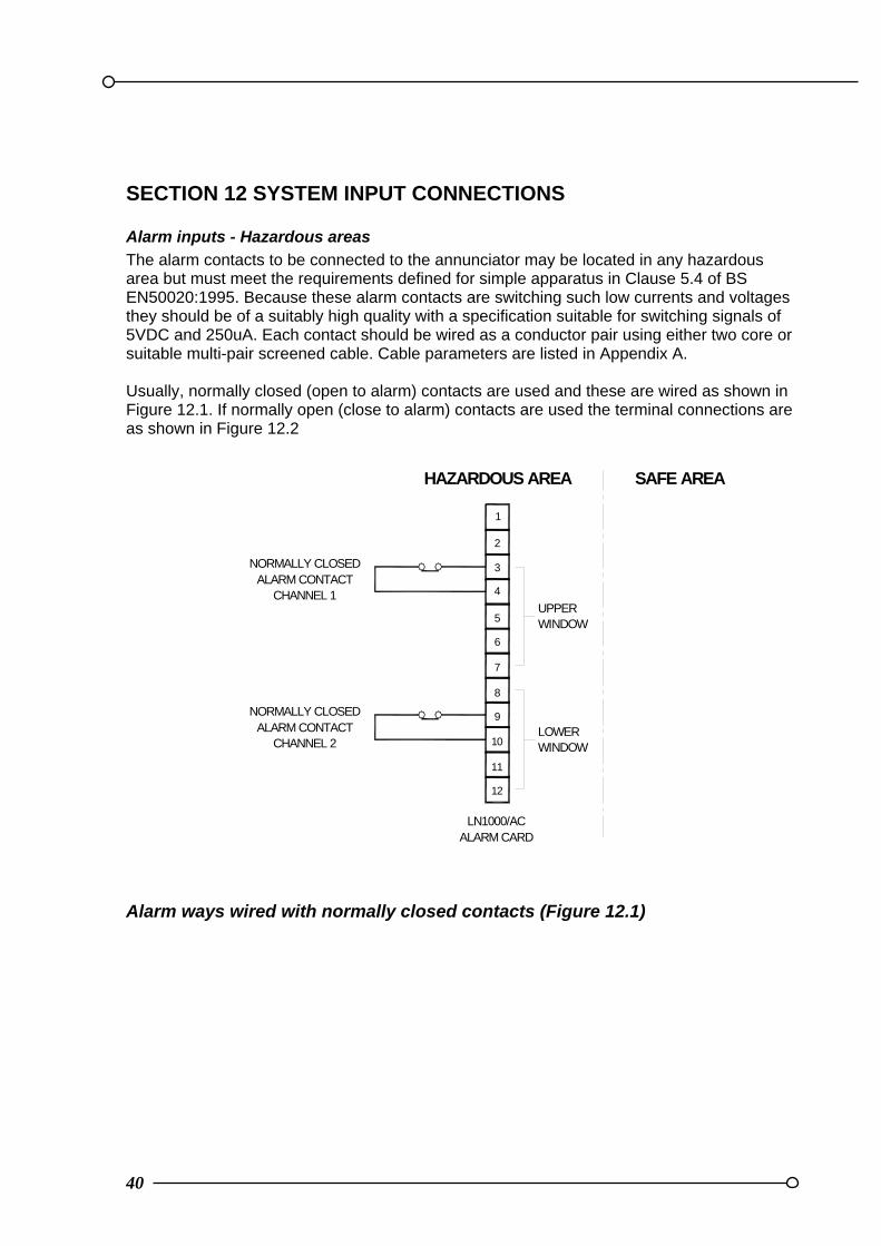
SECTION 12 SYSTEM INPUT CONNECTIONS
Alarm inputs - Hazardous areas
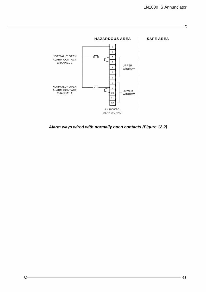
The alarm contacts to be connected to the annunciator may be located in any hazardous area but must meet the requirements defined for simple apparatus in Clause 5.4 of BS EN50020:1995. Because these alarm contacts are switching such low currents and voltages they should be of a suitably high quality with a specification suitable for switching signals of 5VDC and 250uA. Each contact should be wired as a conductor pair using either two core or suitable multi-pair screened cable. Cable parameters are listed in Appendix A. Usually, normally closed (open to alarm) contacts are used and these are wired as shown in Figure 12.1. If normally open (close to alarm) contacts are used the terminal connections are as shown in Figure 12.2
Alarm ways wired with normally closed contacts (Figure 12.1)
6
CHANNEL 2ALARM CONTACT
NORMALLY CLOSED
12
LN1000/ACALARM CARD
9
11
10
8
7
LOWERWINDOW
CHANNEL 1ALARM CONTACT
NORMALLY CLOSED
HAZARDOUS AREA
3
5
4
2
1
WINDOWUPPER
SAFE AREA
LN1000 IS Annunciator
41
Alarm ways wired with normally open contacts (Figure 12.2)
12
11
10
9
8
7
6
5
4
3
2
1
LN1000/ACALARM CARD
UPPERWINDOW
HAZARDOUS AREA SAFE AREA
LOWERWINDOW
ALARM CONTACTCHANNEL 1
ALARM CONTACTCHANNEL 2
NORMALLY OPEN
NORMALLY OPEN
42
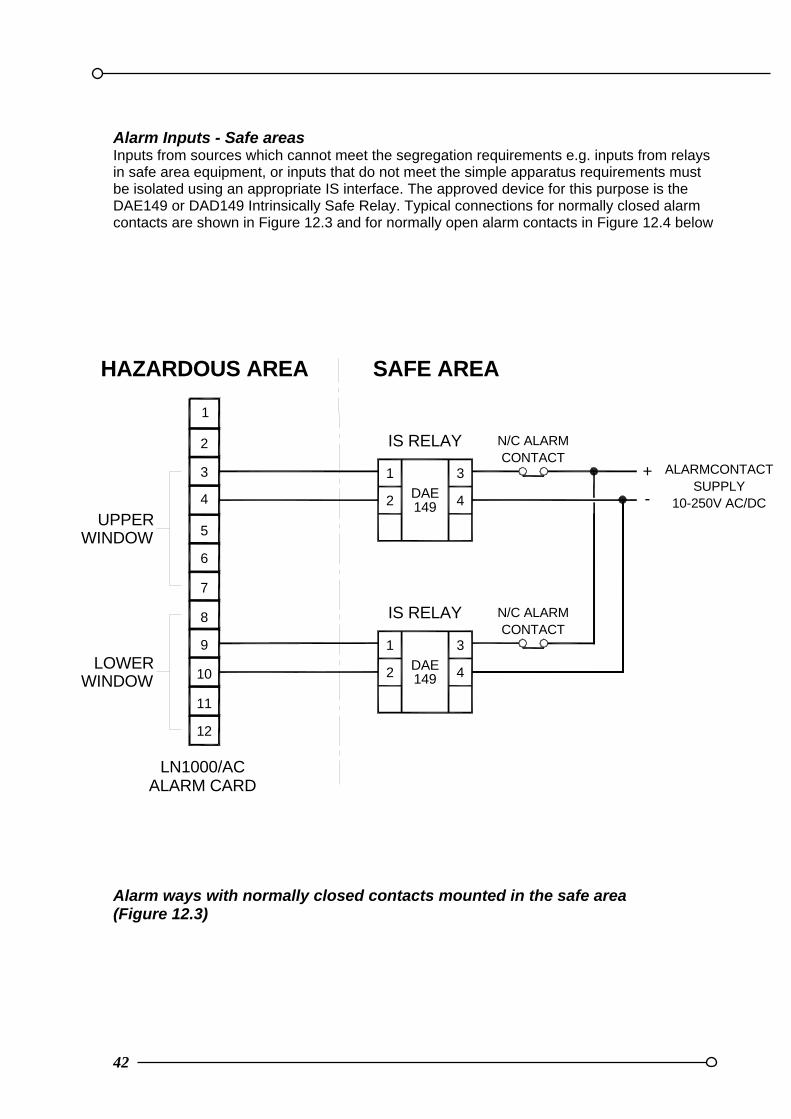
Alarm Inputs - Safe areas Inputs from sources which cannot meet the segregation requirements e.g. inputs from relays in safe area equipment, or inputs that do not meet the simple apparatus requirements must be isolated using an appropriate IS interface. The approved device for this purpose is the DAE149 or DAD149 Intrinsically Safe Relay. Typical connections for normally closed alarm contacts are shown in Figure 12.3 and for normally open alarm contacts in Figure 12.4 below
Alarm ways with normally closed contacts mounted in the safe area (Figure 12.3)
12
11
10
9
8
7
6
5
4
3
2
1
LN1000/ACALARM CARD
UPPERWINDOW
HAZARDOUS AREA SAFE AREA
LOWERWINDOW
IS RELAY
2
1
4
3
DAE149
IS RELAY
2
1
4
3
DAE149
+
-
N/C ALARMCONTACT
N/C ALARMCONTACT
ALARMCONTACTSUPPLY
10-250V AC/DC
LN1000 IS Annunciator
43
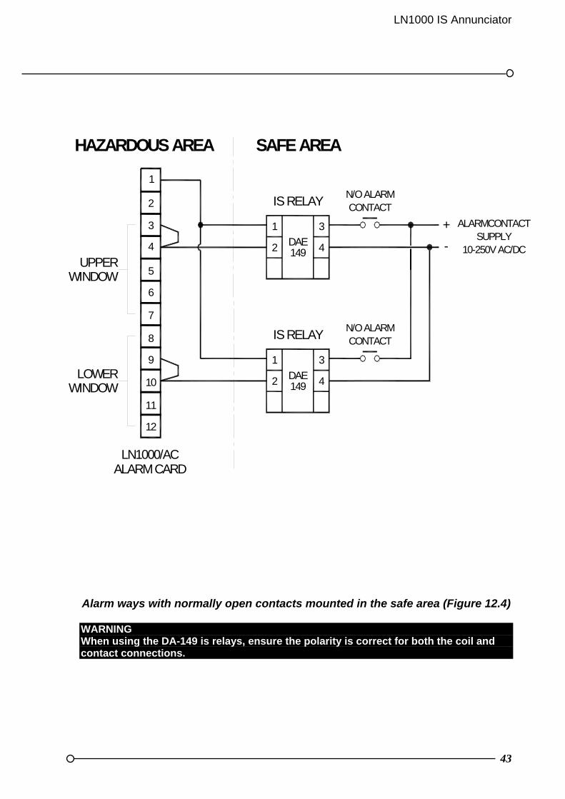
Alarm ways with normally open contacts mounted in the safe area (Figure 12.4) WARNING When using the DA-149 is relays, ensure the polarity is correct for both the coil and contact connections.
12
11
10
9
8
7
6
5
4
3
2
1
LN1000/ACALARM CARD
UPPERWINDOW
HAZARDOUS AREA SAFE AREA
LOWERWINDOW
IS RELAY
2
1
4
3
DAE149
IS RELAY
2
1
4
3
DAE149
+
-
N/O ALARMCONTACT
N/O ALARMCONTACT
ALARMCONTACTSUPPLY
10-250V AC/DC

44
Inhibit Inputs
Terminals are provided for connecting links to inhibit the alarm function for plant start up or commissioning. Each alarm card should have these links wired separately. The length of each connection should not exceed 100mm. Inhibit channel 1: Connect terminal 1 to terminal 7 Inhibit channel 2: Connect terminal 1 to terminal 8
External pushbutton inputs
A set of membrane pushbuttons is provided as standard on the annunciator fascia panel. These can be disabled by jumper links. Where required, an additional or replacement set of pushbuttons may be connected to the Sequence Card terminals for remote use. Good quality pushbuttons should be used with contacts suitable for 5VDC with a low current capability of 0.1mA. They must meet the requirements defined for simple apparatus in Clause 5.4 of BS EN50020. They should be separated from other electrical equipment and isolated from earth. If these requirements cannot be met the signals must be isolated by the use of the appropriate IS relay, i.e. DAD149 for IS signals or DAE149 for non IS signals. Remote pushbuttons should be connected using the normally open contacts. Terminal connections are shown in Figure 12.5 below
Remote pushbutton connections (Figure 12.5)
LN1000/SC SEQUENCE CARD
HAZARDOUS AREA
RESET
ACKNOWLEDGE
SILENCE
7T
12
11
10
9
8 TEST
R
A
S
3
6
5
4
2
1 SAFE AREA
LN1000 IS Annunciator
45
SECTION 13 SYSTEM OUTPUT CONNECTIONS
General
In addition to the audible output signals there are various additional outputs available from the annunciator. These can be used to trigger control action from the safe area or activate further alarms. These outputs can be common to the system or individual to each channel.
Audible outputs
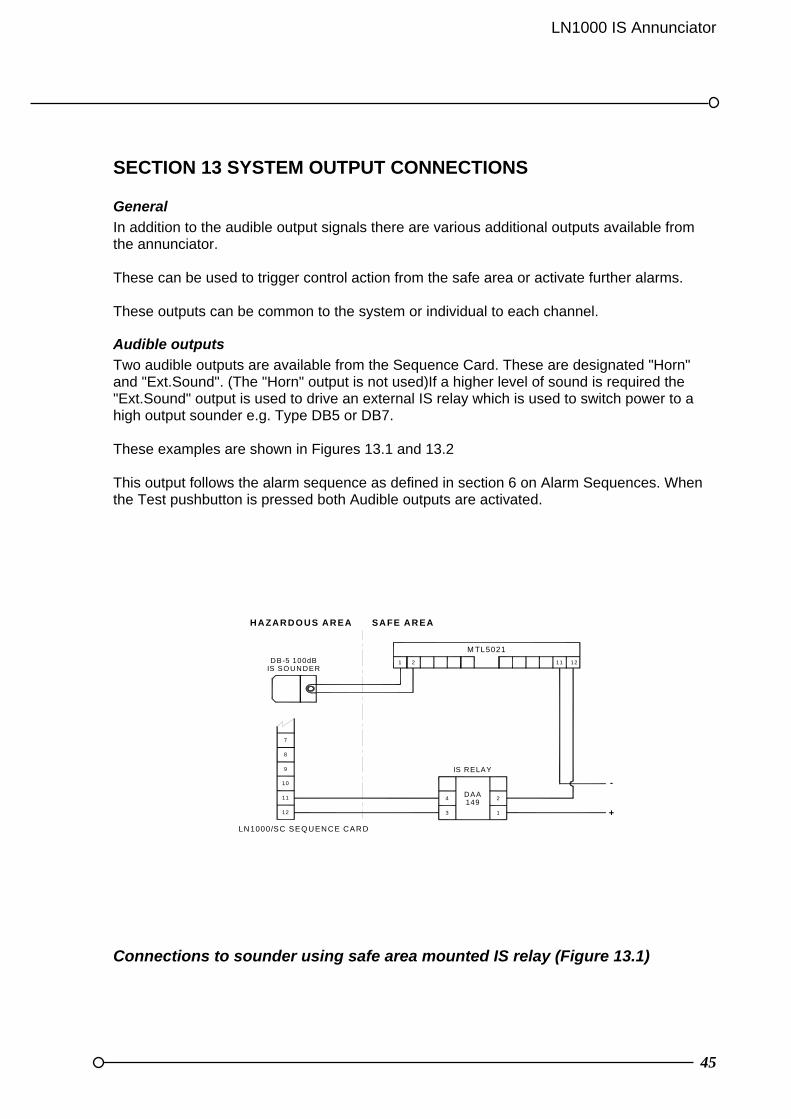
Two audible outputs are available from the Sequence Card. These are designated "Horn" and "Ext.Sound". (The "Horn" output is not used)If a higher level of sound is required the "Ext.Sound" output is used to drive an external IS relay which is used to switch power to a high output sounder e.g. Type DB5 or DB7. These examples are shown in Figures 13.1 and 13.2 This output follows the alarm sequence as defined in section 6 on Alarm Sequences. When the Test pushbutton is pressed both Audible outputs are activated.
Connections to sounder using safe area mounted IS relay (Figure 13.1)
IS RELAY
LN1000/SC SEQ UENCE CARD
8
10
11
12
9
7
4
3
149DAA
HAZARDO US AREA
DB-5 100dBIS SO UN DER
SAFE AREA
21
+
2
1
-
11 12
M TL5021

46
To reduce the amount of wiring between safe and hazardous areas it is possible to use an alternative hazardous area mounting IS Relay (DAD149). This configuration is shown in Figure 13.3 Connections to sounder using hazardous area mounted IS relay (Figure 13.2) WARNING When using the DA-149 is relays, ensure the polarity is correct for both the coil and contact connections.
LN1000/SC SEQUENCE CARD
12
11
8
9
10
7
DAD149
3
4
1
2
IS RELAY
SAFE AREAHAZARDOUS AREA
DB-5 100dBIS SOUNDER
1 2 11
-
+
12
MTL5021
LN1000 IS Annunciator
47
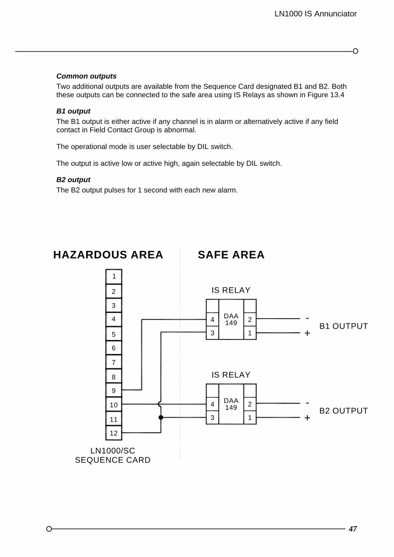
Common outputs
Two additional outputs are available from the Sequence Card designated B1 and B2. Both these outputs can be connected to the safe area using IS Relays as shown in Figure 13.4
B1 output
The B1 output is either active if any channel is in alarm or alternatively active if any field contact in Field Contact Group is abnormal. The operational mode is user selectable by DIL switch. The output is active low or active high, again selectable by DIL switch.
B2 output
The B2 output pulses for 1 second with each new alarm.
Connections from common outputs using safe area mounted IS relays (Figure 13.3)
12
11
10
9
8
7
6
5
4
3
2
1
HAZARDOUS AREA SAFE AREA
IS RELAY
2DAA149
IS RELAY
DAA149
-
+B1 OUTPUT
1
2
1
4
3
4
3B2 OUTPUT
-
+
LN1000/SCSEQUENCE CARD
48
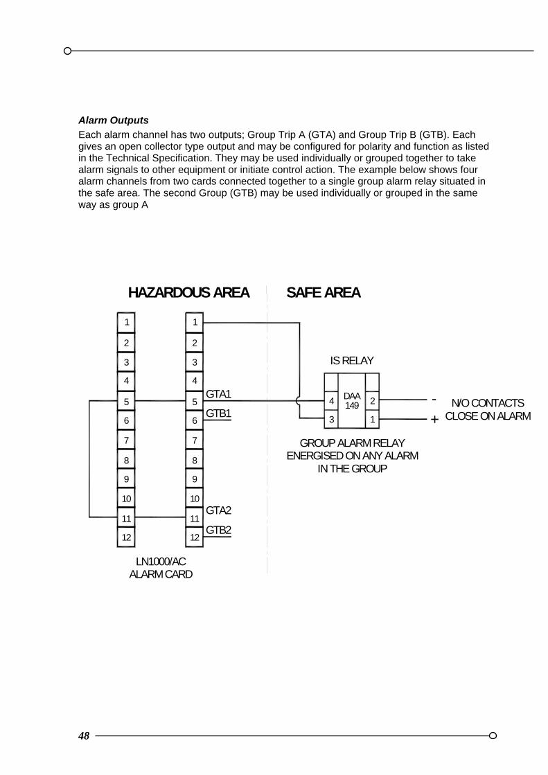
Alarm Outputs
Each alarm channel has two outputs; Group Trip A (GTA) and Group Trip B (GTB). Each gives an open collector type output and may be configured for polarity and function as listed in the Technical Specification. They may be used individually or grouped together to take alarm signals to other equipment or initiate control action. The example below shows four alarm channels from two cards connected together to a single group alarm relay situated in the safe area. The second Group (GTB) may be used individually or grouped in the same way as group A
Group Trip output connections (Figure 13.4)
12
11
10
9
8
7
6
5
4
3
2
1
LN1000/ACALARM CARD
HAZARDOUS AREA SAFE AREA
IS RELAY
2DAA149 N/O CONTACTS
1
4
3
12
11
10
9
8
7
6
5
4
3
2
1
CLOSE ON ALARM
GROUP ALARM RELAYENERGISED ON ANY ALARM
IN THE GROUP
GTB1
GTB2
GTA2
+-GTA1
LN1000 IS Annunciator
49
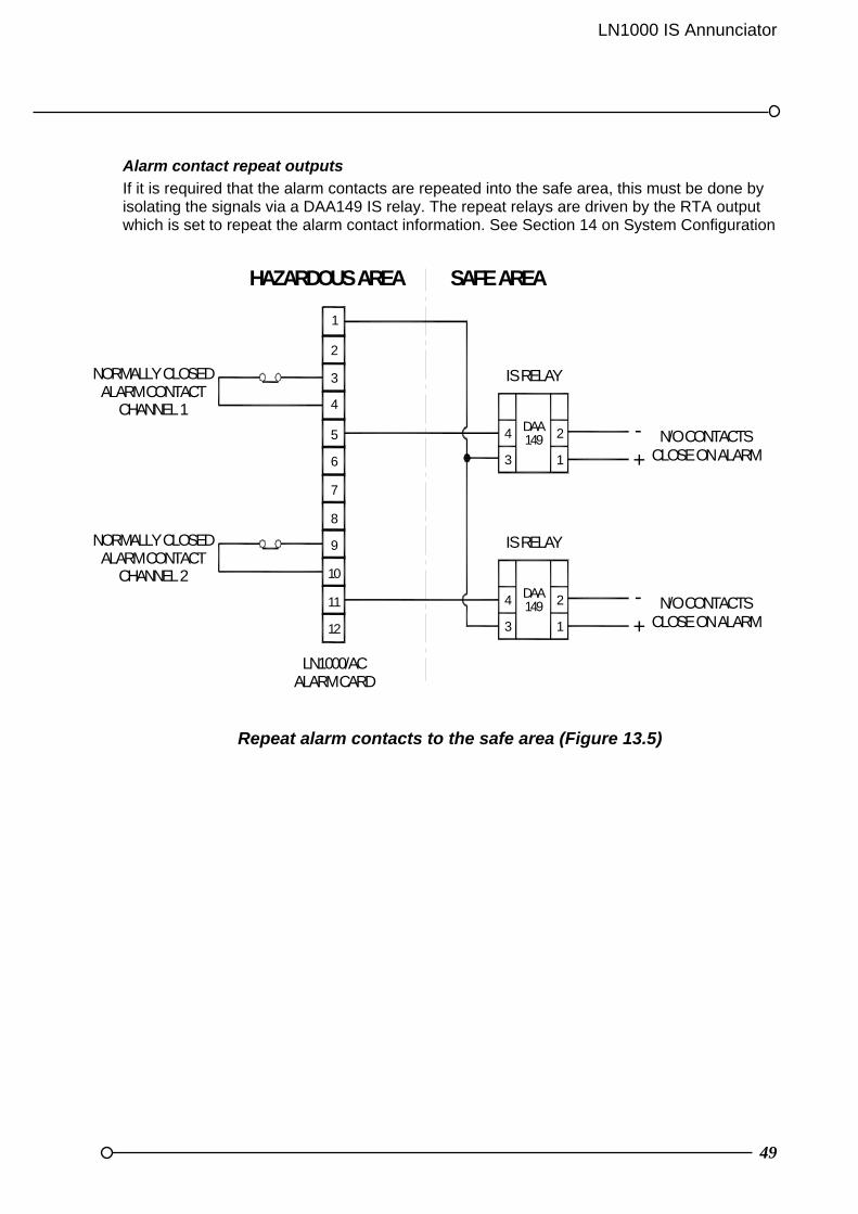
Alarm contact repeat outputs
If it is required that the alarm contacts are repeated into the safe area, this must be done by isolating the signals via a DAA149 IS relay. The repeat relays are driven by the RTA output which is set to repeat the alarm contact information. See Section 14 on System Configuration
Repeat alarm contacts to the safe area (Figure 13.5)
12
11
10
9
8
7
6
5
4
3
2
1
LN1000/ACALARM CARD
HAZARDOUS AREA SAFE AREA
IS RELAY
2DAA149 N/O CONTACTS
1
4
3 CLOSE ON ALARM
IS RELAY
2DAA149 N/O CONTACTS
1
4
3 CLOSE ON ALARM
NORMALLY CLOSEDALARM CONTACT
CHANNEL 1
NORMALLY CLOSEDALARM CONTACT
CHANNEL 2
-+
-+

50
SECTION 14 SYSTEM CONFIGURATION & PROGRAMMING
General
To configure the system for your particular requirements DIL switches are set on the Sequence Card (LN1000-SC) for system configuration and on each Alarm Card (LN1000-AC) for individually configuring each alarm channel. Unless otherwise specified all switches will be configured in the default position which is UP To gain access to the DIL switches firstly remove the fascia. The settings can be made with cards mounted in the case or alternatively the cards can be removed to set up DIL switches and potentiometers. Refer to Section 8 for fascia and card removal and re-fitting WARNING The DIL switch settings are only read on power up so the equipment must be switched off and back on again before any configuration changes are registered.
Commons Card DIL Switch Settings
The location of the DIL switches are shown in the diagram below.
The DIL switch details are given below:
SW FUNCTION UP DOWN 1 B1 Output mode Alarm sequence Field contacts 2 Audible re-sound time bit 2 Min Max 3 Audible re-sound time bit 1 Min Max 4 Audible re-sound time bit 0 Min Max 5 B1 Output polarity Low High
6-10 Unused
10
1
10
1
RIBBON CABLE TOPUSHBUTON CARD
DIL SWITCH
COMPONENTSIDE OF BOARD
DIL SWITCH
LN1000 IS Annunciator
51
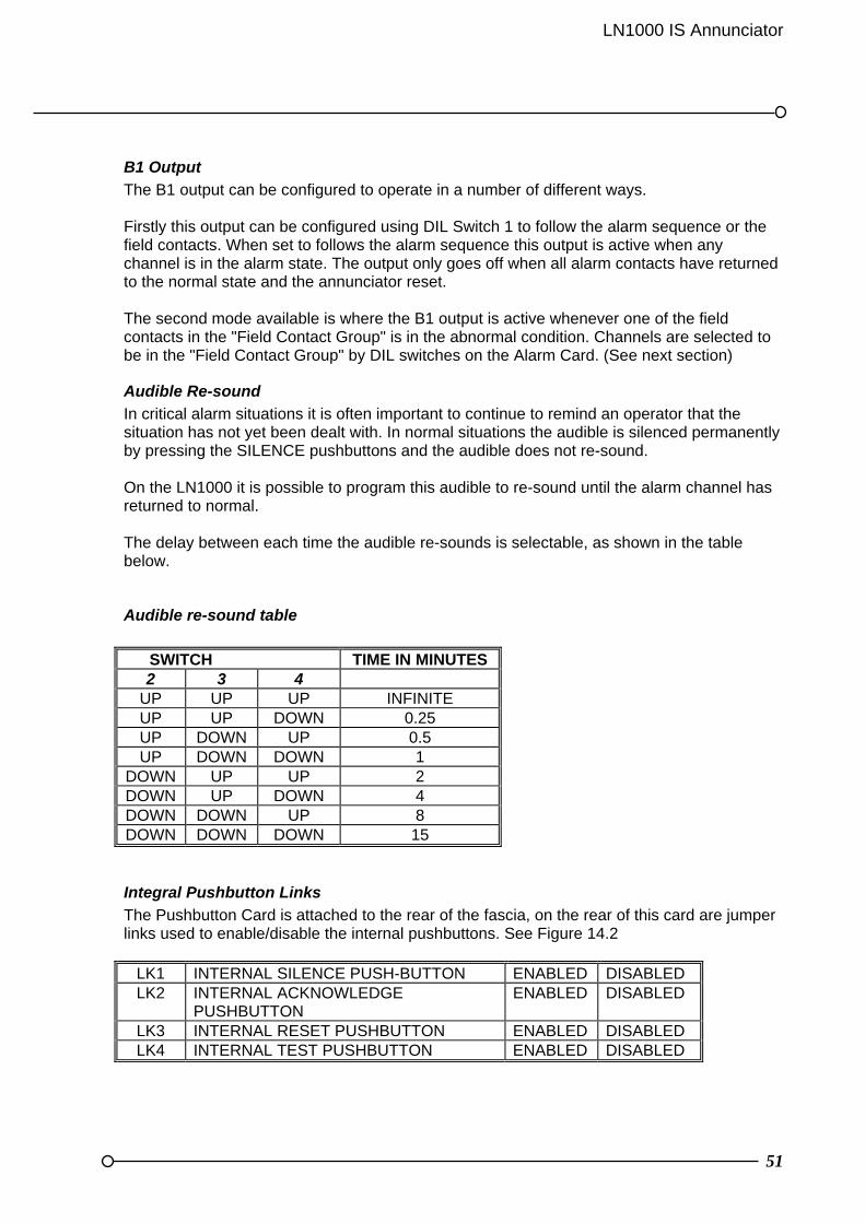
B1 Output
The B1 output can be configured to operate in a number of different ways. Firstly this output can be configured using DIL Switch 1 to follow the alarm sequence or the field contacts. When set to follows the alarm sequence this output is active when any channel is in the alarm state. The output only goes off when all alarm contacts have returned to the normal state and the annunciator reset. The second mode available is where the B1 output is active whenever one of the field contacts in the "Field Contact Group" is in the abnormal condition. Channels are selected to be in the "Field Contact Group" by DIL switches on the Alarm Card. (See next section)
Audible Re-sound
In critical alarm situations it is often important to continue to remind an operator that the situation has not yet been dealt with. In normal situations the audible is silenced permanently by pressing the SILENCE pushbuttons and the audible does not re-sound. On the LN1000 it is possible to program this audible to re-sound until the alarm channel has returned to normal. The delay between each time the audible re-sounds is selectable, as shown in the table below.
Audible re-sound table
SWITCH TIME IN MINUTES 2 3 4
UP UP UP INFINITE UP UP DOWN 0.25 UP DOWN UP 0.5 UP DOWN DOWN 1
DOWN UP UP 2 DOWN UP DOWN 4 DOWN DOWN UP 8 DOWN DOWN DOWN 15
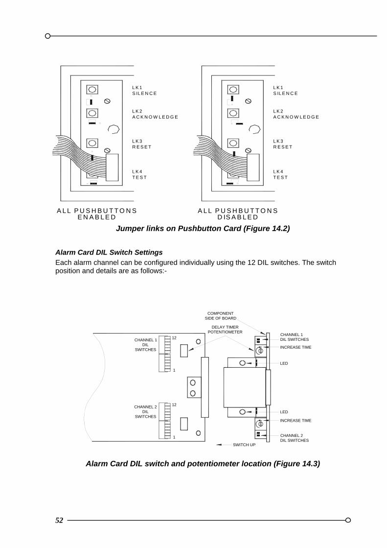
Integral Pushbutton Links
The Pushbutton Card is attached to the rear of the fascia, on the rear of this card are jumper links used to enable/disable the internal pushbuttons. See Figure 14.2
LK1 INTERNAL SILENCE PUSH-BUTTON ENABLED DISABLED LK2 INTERNAL ACKNOWLEDGE
PUSHBUTTON ENABLED DISABLED
LK3 INTERNAL RESET PUSHBUTTON ENABLED DISABLED LK4 INTERNAL TEST PUSHBUTTON ENABLED DISABLED
52
Jumper links on Pushbutton Card (Figure 14.2)
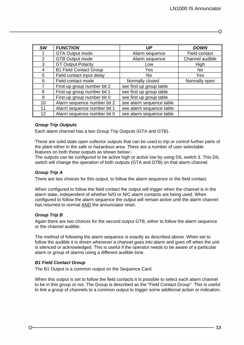
Alarm Card DIL Switch Settings
Each alarm channel can be configured individually using the 12 DIL switches. The switch position and details are as follows:-
Alarm Card DIL switch and potentiometer location (Figure 14.3)
L K 1S IL E N C E
A L L P U S H B U T T O N S
L K 2A C K N O W L E D G E
L K 3R E S E T
L K 4T E S T
L K 1S IL E N C E
A L L P U S H B U T T O N S
L K 2A C K N O W L E D G E
L K 3R E S E T
L K 4T E S T
D IS A B L E DE N A B L E D
1
12
12
1
CHANNEL 1DIL
SWITCHES
CHANNEL 2DIL
SWITCHES
LED
CHANNEL 1DIL SWITCHES
LED
CHANNEL 2DIL SWITCHES
INCREASE TIME
COMPONENTSIDE OF BOARD
DELAY TIMERPOTENTIOMETER
INCREASE TIME
SWITCH UP
LN1000 IS Annunciator
53
SW FUNCTION UP DOWN 1 GTA Output mode Alarm sequence Field contact 2 GTB Output mode Alarm sequence Channel audible 3 GT Output Polarity Low High 4 B1 Field Contact Group Yes No 5 Field contact input delay No Yes 6 Field contact mode Normally closed Normally open 7 First-up group number bit 2 see first up group table 8 First-up group number bit 1 see first up group table 9 First-up group number bit 0 see first up group table
10 Alarm sequence number bit 2 see alarm sequence table 11 Alarm sequence number bit 1 see alarm sequence table 12 Alarm sequence number bit 0 see alarm sequence table
Group Trip Outputs
Each alarm channel has a two Group Trip Outputs (GTA and GTB). These are solid state open collector outputs that can be used to trip or control further parts of the plant either in the safe or hazardous area. There are a number of user selectable features on both these outputs as shown below:- The outputs can be configured to be active high or active low by using DIL switch 3. This DIL switch will change the operation of both outputs (GTA and GTB) on that alarm channel.
Group Trip A
There are two choices for this output, to follow the alarm sequence or the field contact. When configured to follow the field contact the output will trigger when the channel is in the alarm state, independent of whether N/O or N/C alarm contacts are being used. When configured to follow the alarm sequence the output will remain active until the alarm channel has returned to normal AND the annunciator reset.
Group Trip B
Again there are two choices for the second output GTB, either to follow the alarm sequence or the channel audible. The method of following the alarm sequence is exactly as described above. When set to follow the audible it is driven whenever a channel goes into alarm and goes off when the unit is silenced or acknowledged. This is useful if the operator needs to be aware of a particular alarm or group of alarms using a different audible tone.
B1 Field Contact Group
The B1 Output is a common output on the Sequence Card. When this output is set to follow the field contacts it is possible to select each alarm channel to be in this group or not. The Group is described as the "Field Contact Group". This is useful to link a group of channels to a common output to trigger some additional action or indication.

54
Alarm Input Delay
Field contact input delay is active when DIL switch 5 is set Down. The time delay can then be adjusted between 3 and 30 seconds by adjusting the channel's delay time potentiometer situated on the front of the Alarm Card. Increase the delay time by turning clockwise.
Field Contact Mode
Each alarm channel can be configured as N/C (open to alarm) or N/O (close to alarm). To change from N/C to N/O DIL switch (SW6) is used and the wiring must be modified as shown in Section 12 on System Inputs Connections.
First-up Group
The first-up facility is often an essential feature for the alarm annunciator to inform the operator which alarm was the first to occur in a sequence of events. If a single annunciator is monitoring different unrelated areas of the plant it is possible to have different first-up groups for these different areas. These are programmed into the different groups as shown below. If it is required to have some alarm channels with a first-up facility and others without then those alarms that do not have the first-up facility should be programmed with a suitable sequence and also set in the group for non first-up sequences.
First up group table
SWITCH FIRST UP GROUP 7 8 9
UP UP UP Non First-Up sequences UP UP DOWN Group 1 UP DOWN UP Group 2 UP DOWN DOWN Group 3
DOWN UP UP Group 4 DOWN UP DOWN Group 5 DOWN DOWN UP Group 6 DOWN DOWN DOWN Group 7
Alarm Sequence
Each alarm way can be individually setup to indicate alarm conditions using a particular ISA alarm sequence. There are six possible selections, three standard and three with the first-up facility. These selections will cover most commonly used alarm sequences. For full details on the alarm sequences please refer to Section 6 and the standard ISA reference document "Annunciator Sequences and Specifications S18.1-1979.

LN1000 IS Annunciator
55
Alarm sequence table
SWITCH ISA ALARM SEQUENCE 10 11 12 UP UP UP A UP UP DOWN M UP DOWN UP R
DOWN UP UP F1A DOWN UP DOWN F2M DOWN DOWN UP F3A

56
SECTION 15 COMMISSIONING Commissioning and servicing operations must be carried out by a qualified technician properly trained and authorised to work on intrinsically safe electronic equipment in hazardous environments.
Tools required
Tools required are: Small straight blade screwdriver for terminals Medium straight blade screwdriver for terminal cover and panel mounting brackets RTK supplied Double Hex 8mm socket for removal of front fascia IS approved Multimeter (at least 20kohm/V)
Commissioning
1 Check all alarm contacts, external devices and remote pushbuttons for earth faults. 2 Check that all cables installed in the hazardous area are installed in accordance with proper IS practice. 3 Check that all cables installed in the hazardous areas comply with the cable
parameters specified in Appendix A and in the certification documents. 4 Check that all wires are correctly terminated. 5 Power up and check the supply voltage between Terminal 1 & 2 on the Sequence
Card this should be between 7.5V and 8.5VDC. 6 Press the Test button and check all LED's, all segments of LCD's and any audibles connected to the system operate correctly. 7 With all field contacts normal initiate the System Test sequence by pressing and
holding for 3 seconds the Silence and Test pushbuttons together. The test simulated an alarm condition on all channels. All audible outputs are driven but not the group outputs. The Acknowledge and Reset pushbuttons are pressed to clear the alarms.
8 Set an alarm contact to abnormal and check the LED, LCD, audible and other outputs follow the ISA sequences specified. Complete the process by pressing Silence, Acknowledge, returning the field contact to normal and pressing the Reset buttons. 9 Set several alarm contacts to abnormal and repeat the test detailed in part (8) above.
This time also check that the first-up and only the first-up alarm is showing the "F" correctly
10 Systematically check every alarm channel as part (8) above.
LN1000 IS Annunciator
57
SECTION 16 TROUBLE SHOOTING For these checks the annunciator fascia and terminal cover can be removed whilst the unit is powered.
There is no displays visible on either LCD or LED - Check
1. The power to the IS Isolator is switched on 2. The output from the IS Isolator is correct 3. The unit has not been connected directly to 24VDC 4. Inspect the Sequence Card for signs of burnt components
Displays do not operate when Test pushbutton pressed - Check
1. Voltage between Commons Card terminal 1 & 2 2. IS Isolator fuse not blown? 3. Power supply correctly wired 4. Sequence Card correctly installed 5. No earth fault on remote pushbutton controls (when fitted) 6. Field wiring is correct
All alarm channels function incorrectly - Check
1. Sequence Card correctly installed 2. Field contact wiring is correct 3. Alarm sequence is set correctly on Alarm Card DIL switches 10, 11 and 12 4. No earth fault on remote pushbutton controls (when fitted) 5. Check functioning of Sequence Card by replacement
One channel functions incorrectly - Check
1. Alarm Card correctly installed 2. Alarm sequence is set correctly on Alarm Card DIL switches 10, 11 & 12 3. No earth fault on field contact and wiring 4. Connection is neither open nor short circuited 5. Wiring is terminated correctly 6. Check functioning of Alarm Card by replacement
The DIL Switch programming does not function - Check
1. The DIL switches have been set correctly 2. The unit has been powered down to read the new DIL switch settings 3. Is the fault related to all cards or just one 4. If just one card, check fault by card replacement
The audible is not working correctly - Check
1. If a horn is being used is it connected to the Horn connections on the Sequence Card (Terminals 3 and 4)
2. If an external sounder is used (e.g. DB-5) is this driven via a DA-149 Relay from the EXT SOUND Output on the Sequence Card (Terminals 11 and 12)
58
The IS Relays are not switching correctly - Check
1. Has the correct type of relay been specified? 2. Has the relay polarity been connected correctly for both the coil and the contact
connections? 3. Check the annunciator card by replacement
Routine maintenance
1 Keep the system free from dust and clean the front fascia and any plastic
labels using a dry cloth to lightly wipe the surface. For ingrained dirt we suggest a water dampened cloth is used to lightly wipe the surface, however, please avoid the clear area of the window to avoid clouding.
2 At the beginning of each working shift, press the Test pushbutton and check
that all LED’s, LCD’s displays and audibles are functioning correctly
3 At regular intervals (established by operational experience) check the correct operation of all alarm channels. These checks should be made by a qualified technician / engineer and records kept of the test schedule
4 Include the LN1000 system in the inspection schedule for IS equipment
Recommended Spares
The LN1000 system is very reliable. If the annunciator is essential to the safe operation of the plant it is recommended that a stock of the following spares is maintained: 1 LN1000-AC Alarm Card 1 LN1000-SC Sequence Card 1 MTL5021 IS Isolator 1 Power Supply Unit RT Series
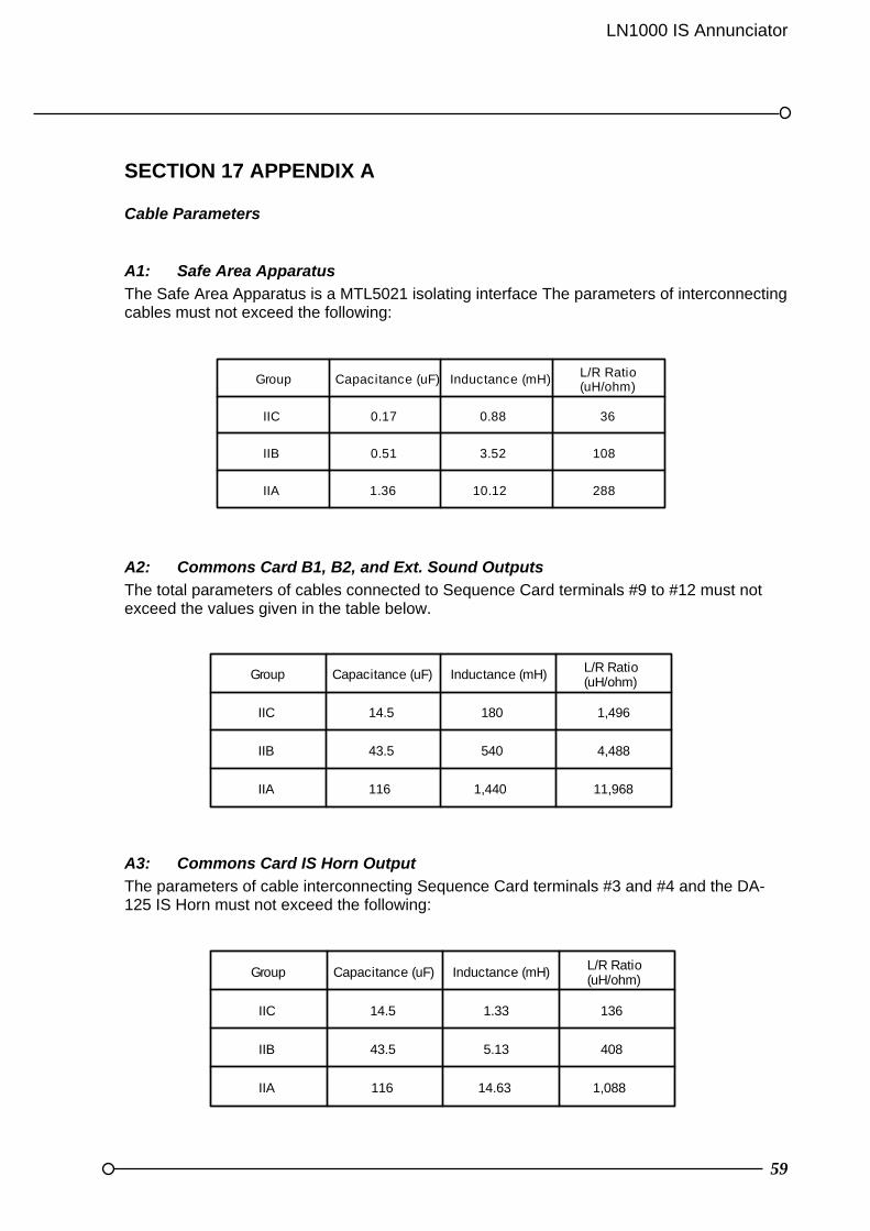
LN1000 IS Annunciator
59
SECTION 17 APPENDIX A
Cable Parameters
A1: Safe Area Apparatus
The Safe Area Apparatus is a MTL5021 isolating interface The parameters of interconnecting cables must not exceed the following:
A2: Commons Card B1, B2, and Ext. Sound Outputs
The total parameters of cables connected to Sequence Card terminals #9 to #12 must not exceed the values given in the table below.
A3: Commons Card IS Horn Output
The parameters of cable interconnecting Sequence Card terminals #3 and #4 and the DA-125 IS Horn must not exceed the following:
Group Capacitance (uF) Inductance (mH) L/R Ratio(uH/ohm)
IIC 0.17 0.88 36
IIB 0.51 3.52 108
IIA 1.36 10.12 288
Group Capacitance (uF) Inductance (mH) L/R Ratio(uH/ohm)
IIC 14.5 180 1,496
IIB 43.5 540 4,488
IIA 116 1,440 11,968
Group Capacitance (uF) Inductance (mH) L/R Ratio(uH/ohm)
IIC 14.5 1.33 136
IIB 43.5 5.13 408
IIA 116 14.63 1,088

60
A4: Commons Card Remote Pushbutton Station
The total combined parameters of load and cables connected to Commons Card terminals #5 to #8 and #12 must not exceed:
A5: Alarm Card Connections
On the LN1000/12 the alarm card terminals are identified by the AL1 to AL6 (AL X) markings on the backplane. On the LN1000/32 the alarm card terminals are identified by the AL1 to AL8 (AL X) markings on the top and the bottom backplanes. Terminals AL X #7 and #8 must only be connected to AL X #1, by separate connections with a maximum connection length of 100mm. For each alarm card the total combined parameters of interconnecting cables and any connected load for AL X terminals #1 to #6 and #9 to #12 must not exceed:
Group Capacitance (uF) Inductance (mH) L/R Ratio(uH/ohm)
IIC 14.5 320 2,080
IIB 43.5 660 6,240
IIA 116 2,560 16,640
Group Capacitance (uF) Inductance (mH) L/R Ratio(uH/ohm)
IIC 14.5 32 613
IIB 43.5 96 1,839
IIA 116 256 4,904

LN1000 IS Annunciator
61
LN1000 Anti-static Precautions Static Electricity can cause serious, permanent damage to unprotected electronic equipment. Everyday activities such as walking across a carpet, working at a bench, or simply handling items can generate large static voltages. Clothing is a common source of static electricity, particularly garments made from man-made fibres such as nylon. Even cotton clothing can generate significant static at low humidity levels. There are other, less familiar, causes of static electricity. Air conditioning systems, for example, can produce significant levels of ambient static charge. Unwrapping goods packaged in plastic film, bubble-wrap and expanded polystyrene can also generate high levels of static electricity. Electrostatic Discharge (ESD) occurs when the static charge held by an item (such as a screwdriver or a finger) is transferred to another item at a different electrical potential. This common phenomenon often results in a noticeable "crack" or "zap" at the point of discharge. Note, however, that serious damage can occur at relatively low static potentials that do not necessarily cause a "zap" - ESD does not always advertise its presence! The LN1000 has been designed to withstand ESD strikes to the casing and terminals. In common with most Printed Circuit Boards (PCB) the Alarm Cards and Commons Card contain sensitive components that can be damaged by voltages as low as a few tens of volts. Consequently, since activities such as walking across a sealed concrete floor, or just working at a bench, can generate static charges of several thousand volts, it follows that the PCB circuits can easily be damaged. It is important to be aware of this risk when configuring the LN1000, since this involves opening the case and adjusting dip switches, links and potentiometers on the PCB's. To minimise the risk of static damage, always configure the units using ESD Protection techniques. Earthed wrist straps and anti-static overalls should also be worn to dissipate static charge which can build up on personnel. Ionizers and humidifiers can also be employed to neutralise ambient static charge. Full details on the EPA can be found in British Standard BSEN100015-1: Protection of Electrostatic Sensitive Devices. The likelihood of ESD damage can be eliminated by observing the following precautions: 1. Configure the LN1000 using appropriate ESD protection techniques 2. Always use an earthed wrist strap and, if possible, wear anti-static overalls 3. Minimise touching sensitive points on the PCB such as the link pins, and do not touch
any other components 4. Ensure the Alarm Cards and Commons Card are only handled by personnel familiar
with anti-static precautions 5. Keep all conductive material, food and drink, away from the PCB's and the open annunciator
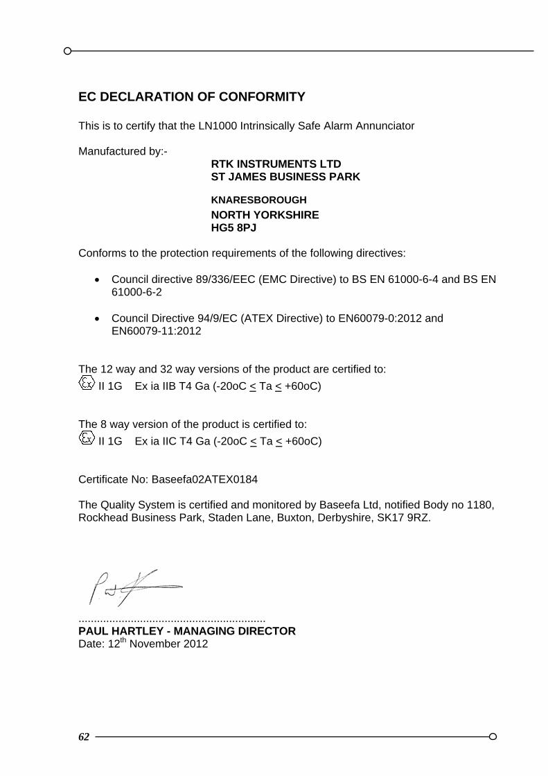
62
EC DECLARATION OF CONFORMITY This is to certify that the LN1000 Intrinsically Safe Alarm Annunciator Manufactured by:-
RTK INSTRUMENTS LTD ST JAMES BUSINESS PARK
KNARESBOROUGH
NORTH YORKSHIRE HG5 8PJ
Conforms to the protection requirements of the following directives:
Council directive 89/336/EEC (EMC Directive) to BS EN 61000-6-4 and BS EN 61000-6-2
Council Directive 94/9/EC (ATEX Directive) to EN60079-0:2012 and
EN60079-11:2012 The 12 way and 32 way versions of the product are certified to:
II 1G Ex ia IIB T4 Ga (-20oC < Ta < +60oC) The 8 way version of the product is certified to:
II 1G Ex ia IIC T4 Ga (-20oC < Ta < +60oC) Certificate No: Baseefa02ATEX0184 The Quality System is certified and monitored by Baseefa Ltd, notified Body no 1180, Rockhead Business Park, Staden Lane, Buxton, Derbyshire, SK17 9RZ.
............................................................. PAUL HARTLEY - MANAGING DIRECTOR Date: 12th November 2012

LN1000 IS Annunciator
63
OTHER RTK PRODUCTS RTK Instruments Ltd is fully ISO9001:2008 approved and manufactures a comprehensive range of complementary products from our factory in Knaresborough, UK for use in the Industrial Control and Instrumentation field as per the summary list provided below. All standard products come complete with a 5 year guarantee Sequential event recorder Alarm management systems Programmable remote logic alarm systems Hazardous area alarm systems Trip amplifiers Trip monitoring systems Signal isolators Multi-output isolators Signal converters Frequency converters Tachometers and inverse tachometers Universal panel meters Large character displays Power supplies Loop powered isolators and displays Intrinsically safe alarm and status display products including:- LED beacons Sounders Led clusters Please ring the sales office on + 44 (0) 1423 580500 for latest product information or visit our web site www.rtkinstruments.com