Embed Size (px)
Citation preview

Semantic Technologies for DescribingMeasurement Data in Databases
Ulf Noyer, Dirk Beckmann, and Frank Köster
Institute of Transportation Systems, German Aerospace Center{ulf.noyer,dirk.beckmann,frank.koester}@dlr.de
Abstract. Exploration and analysis of vast empirical data is a corner-stone of the development and assessment of driver assistance systems.A common challenge is to apply the domain specific knowledge to the(mechanised) data handling, pre-processing and analysis process.
Ontologies can describe domain specific knowledge in a structured waythat is manageable for both humans and algorithms. This paper outlinesan architecture to support an ontology based analysis process for datastored in databases. Build on these concepts and architecture, a proto-type that handles semantic data annotations is presented. Finally, theconcept is demonstrated in a realistic example. The usage of exchange-able ontologies generally allows the adaption of presented methods fordifferent domains.
1 Introduction
Reliable and safe automation is one foundation for modern traffic systems andpart of concepts for assistance and automation systems. Therefore, for the analy-sis and reflection of users in automated environments, experimental systems (i.e.vehicles and driving simulators) play an important role. They produce exhaustiveamounts of data, which can be used for an evaluation of the considered systemin a realistic environment. Long term studies and naturalistic driving studies [7]result in similar datasets. Much data means a lot of information to interpret andpotential results to discover. Therefore our motivation is, to store derived metadata closely connected with its original data for an integrated processing. Byusing semantic technologies a continuous technical and semantic process can beprovided.
As a starting point, experimental data is to be considered as already storedin the relational database and should not be changed in the process. As many ofthe following principles not only match for measurement data, but in general fortables in relational databases, also the term bulk data is used as an equivalent formeasurement data. So, it is aspired, to use semantic technologies for describingthe database elements to support their interpretation [15]. They allow to for-mally handle complex data structures very flexible and schema knowledge canbe extended easily. This is a demand resulting from the fact, that experimentalsystems are in continuous development and projects touch different knowledgedomains.
G. Antoniou et al. (Eds.): ESWC 2011, Part II, LNCS 6644, pp. 198–211, 2011.c© Springer-Verlag Berlin Heidelberg 2011

Semantic Technologies for Describing Measurement Data in Databases 199
Fig. 1. Tables of a relational database with possible annotations
Figure 1 shows the intended database elements for semantic annotations. Ta-bles containing sensor data of an experiment can be tagged with experimentinformation. Columns can have a semantic annotation about physical unit ofcontaining elements and used sensor for recording. Rows or cells can get an an-notation about bad quality or detected events in the considered elements. Acomplex application case is presented in Sect. 5. More meaningful examples ofgeneric metadata annotations are also discussed in [16,12].
In some of the following considerations it is assumed, that table records havean order, so the statement row is preferred to record or tuple. Also rows areconsidered with the restriction that they must be uniquely identifiably. Theneeded database elements from Fig. 1 are transformed in unique URIs to beused in RDF statements. However, data itself is not transformed, since the valueitself is not used for the presented purposes. Based on this, annotations are usedsimilar to a formal memo or notepad mechanism. As domain knowledge is solelymodelled in exchangeable ontologies, the presented concepts can be also appliedfor other domains.
2 Background and Related Work
This section introduces other work, which is needed for this paper or is relevant.
2.1 Usage of Semantic Technologies
In the last years several metadata technologies evolved, with the aim to makethem better processable by machines. Especially the Resource DescriptionFramework (RDF) is important in this context. Using RDF, a graph with re-lations of the individual metadata elements can be modelled. Resources to bedescribed in RDF get annotated using triples, consisting of a subject, predi-cate and an object. On top of this, statements can be flexibly constructed. Forserializing i.e. RDF/XML or Turtle syntax can be used.
200 U. Noyer, D. Beckmann, and F. Köster
The Web Ontology Language (OWL) is based on principles of RDF and canbe used to formally describe complete ontologies. In an ontology the terms andtheir relations and rules are described. Especially for plain rules there is theSemantic Web Rule Language (SWRL) as an extension of OWL [13].
2.2 RDF-Stores
A RDF-repository [18,1] (triple-store) is used to manage RDF-statements. Itsupports adding, manipulating and searching statements in the repository. Suchrepositories can have different backends to store managed statements. Using re-lational databases as backend is in focus of this document. The statements con-sisting of subject, predicate and object are stored in a separate relation in theunderlying database. Advantages of different optimization strategies are exhaus-tively discussed in [22]. Current repositories often directly support the SimpleProtocol and RDF Query Language (SPARQL). It has for RDF-stores similarimportance as SQL for relational databases.
2.3 Mapping of Relational Databases into RDF
There have been already early approaches to map relational data into RDFfor the integration of relational databases and its contents [5]. In principle, apredefined scheme or rules for mapping the schema of the database and itscontent into RDF statements are used. There are projects ([3,6]), which areconcerned with this functionality. However, both projects are not used for thiswork, because they would be strongly oversized. As shown in Sect. 3.3 justthe mapping of database schema is needed (and not of data itself), what iscomparatively easy. This work also only requires a mapping of the actually useddatabase elements. If in the future also data itself managed in a database shouldbe included in RDF mapping, usage of [6] could be a valuable option. This workis based on the principles discussed in [5].
2.4 Scientific Workflow Systems
The presented paper is distantly related with the field of scientific workflowsystems (SWS, i.e. [2,20]). In SWS a process for evaluation of a data productcan be specified. At execution, each processing step runs consecutively on data.The result of one step is input of the next one. Often SWS offer a graphicalinterface for composition of workflow steps using directed graphs. These systemssupport processing by offering metadata about processing steps and data lineage.Exchanged data products are considered as black boxes by SWS, which are notinterpreted by the system.
But that is the focus of the presented paper, to concentrate on the contentlevel of exchanged data. For that reason micro-annotations are utilized in asimilar way as they are used with web pages [9] or multimedia files [11]. Theaspect of data flow and its composition has only a minor role. In this work it isassumed that time structured data is stored in a database, an unusual restrictionfor classical SWS.

Semantic Technologies for Describing Measurement Data in Databases 201
3 Data Management
The recorded time structured bulk data is stored in a relational database. Allother data either describes these time series or is deduced from it. As a result,all data besides time series is considered as metadata.
3.1 Use Cases
This section presents the identified use cases for semantic annotations.– Manual examination: Using an interface for interaction with annotations
a user can directly interact and manipulate them (cf. Sect. 4). Resources canbe referenced for documentation purposes. It also allows exporting tables withannotations into a flat file format for usage in other applications.
– Services: A service is an automated piece of software, which analyses somegiven data/annotations in the database and creates new data/annotations byapplying specific domain knowledge. It has a web service interface for being ex-ternally triggered. Web services can be easily reused and orchestrated for morecomplex workflow setups or automatically started, after new data has been gath-ered. Furthermore, web services can be also reused by many SWS.
– Application integration: Any arbitrary application can also integrate sup-port for semantic annotations. Ærogator is used for explorative data analysisand can display annotations parallel to time series data [12]. For data miningin time series EAMole is used and could respect annotations under data miningaspects [12].
3.2 Common Architecture
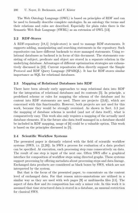
An overview of data storage and access are shown in Fig. 2 [14]. In the bottomlayer, there is a relational database with the internal name Dominion-DataStore.It stores relational bulk data and RDF annotations in completely separated datastructures. All elements in the figure with a horizontal pattern are related tobulk data. Elements with a vertical pattern describe elements connected withsemantic annotations. Measurement data from an experiment is always storedin a new table, so relational database schema is quite simple. In the databasethere are stored procedures available to directly work on RDF annotations withSQL.
Access to RDF statements is more abstracted for an efficient data handling.The triple store abstraction implements the concrete RDF storage. The nativeRDF handling of an Oracle database is used. An alternative would be a databaseproduct independent schema layout (cf. Sect. 2.2). On top of the RDF storageabstraction a common semantic web framework handles RDF graphs [18]. De-pending on the concrete RDF-graph, also RDFS- or OWL- models can be han-dled. Another layer is responsible for mapping required database elements intoresource URIs, to be referenced in RDF statements. Concrete mapping imple-mentation is based on the principles discussed in Sect. 3.3. The RDF store allowsmanaging strictly divided models. So for each new bulk data table a new RDF
202 U. Noyer, D. Beckmann, and F. Köster
Fig. 2. Overview of architecture used for data access
model is used. In this way a good scalability can be reached. Generic informationis stored in a jointly used RDF model.
Strict separation of bulk data and annotations also reflects their differentusage. Afterwards measurement data is not modified anymore. Its meaning ishidden in recorded number values to be interpreted. On top of the bulk data,there is an abstract layer of interpretations. Descriptions (i.e. for columns) oridentified events (i.e. overtaking manoeuvre) from human imaginations are tobe seen there. In contrast to bulk data, there are much less elements. This ab-straction layer is used during analysis, so that there is a high dynamic in thestatements. These statements are usually assertional (ABox). Schema knowledge(TBox) can be edited using Protégé [19] or a Semantic Wiki [17] as known forRDFS/OWL and then be integrated (cf. Sect. 4). The just presented approachis the adaption of commonly discussed multimedia annotations [9,11] for mea-surement data. The term micro-annotations is also adapted from this domain.
3.3 Annotation of Relational Data
In the database, bulk data is organized in relations. RDF-annotations can refer-ence single attribute instances, tuples, attributes, relations, schemas or databases(cf. Fig. 1). Theoretically, same mechanisms could be used to annotate other re-lational database concepts (i.e. keys, constraints). However, those are not consid-ered, since they are not of interest for discussed use cases. For that purpose, anintegration of relational elements in RDF is needed (cf. Sect. 2.3). Since RDF re-quires an unique specifier for every resource, database elements must be mappedinto URIs. The used mapping approach builds on principles of [5].
Relations are uniquely identified by their name table_name. Also attributesof a table have an unique name column_name. For simplicity, slash (/) is notallowed in table_name and column_name. To identify tuples of a relation, theconsidered relation must have an unique key. Currently, an attribute row_id isadded to every relation, which contains unique integers in context of a relationand serves as a surrogate key. By combining the identification of a tuple and an

Semantic Technologies for Describing Measurement Data in Databases 203
attribute, single attribute instances can be referenced. Based on those assump-tions, Table 1 shows building instructions for URIs to identify different databaseelements.
Table 1. Transformation rules for a database element into an URI
DB element Transformation into URIRelation http://www.dlr.de/ts/dominion-datastore/
↪→ table/table_nameAttribute http://www.dlr.de/ts/dominion-datastore/of a relation ↪→ table/table_name/
↪→ column/column_nameTuple http://www.dlr.de/ts/dominion-datastore/of a relation ↪→ table/table_name/row/row_idAttribute http://www.dlr.de/ts/dominion-datastore/instance ↪→ table/table_name/of a relation ↪→ column/column_name/
↪→ row/row_id
An example of an URI, that references an attribute instance of attributeVelocity with a unique key 48 in relation 20100716_105523_drvstate, wouldhave the following form: http://www.dlr.de/ts/dominion-datastore/table/20100716_105523_drvstate/column/VELOCITY/row/48
In the same way, before table name the name of the database instance andthe schema name are also included (Fig. 3). The inversion is well-defined andtherefore URIs can be assigned to their original database elements. Describedapproach does not integrate values of relational bulk data itself into RDF, sincethey are not required (cf. Sect. 2.3).
4 User Interface
The graphical user interface allows to visualize semantic annotations. Duringsequent processing steps it helps to understand temporary results. Fig. 3 showsa screenshot of the application called Semantic Database Browser. In the leftwindow a schema, table or column can be chosen. The main window showsselected tables. Database elements, which have annotations, are highlighted witha colour. When such an annotated element is selected, the bottom window showsthe annotations as a tree. In Fig. 3 the column Velocity is selected in the leftwindow.
The tree representation was selected, as it is very compact, especially com-pared to graph visualizations. Since only the really needed sub-tree is fetchedfrom memory model, this approach preserves resources. However, it must beconsidered, that only outgoing edges of the graph model are drawn. If there arecycles in the graph and the tree is expanded, nodes can appear multiple times.In front of each tree element is a symbol, which indicates the type of the node

204 U. Noyer, D. Beckmann, and F. Köster
Fig. 3. User interface for interactive working with annotations including highlightedelements and a montage showing nationalized labels
(named resource, blank node, property or literal). The option describe proper-ties lets the tree also show properties of properties. In this way i.e. domain- andrange-restrictions of properties can be viewed. Another feature is to optionallyshow labels (identified by rdfs:label [10]) instead of resource names (URIs oranonymous ids). In this case a literal is chosen, which best matches the lan-guage chosen in the user interface (montage Fig. 3). Using the context menu itis also possible to directly open URI-resources with the associated program, i.e.a web-page in a semantic wiki with the web browser.
Since annotations are stored in different models for each bulk data table (cf.Sect. 3.2), they are loaded on demand for the currently shown table. For thatreason interactions with annotations in the interface are generally performedon the base graph model GB. This graph is the union of the actually usedgraphs. That at least includes the generic graph GG, containing annotationsfor database instance, schemas and table schema. Annotations on bulk data,which are always stored in new tables, are managed in separate RDF models.For each table Ti there exists a graph model GTi . Graph GB is manipulatedduring runtime and is the union of generic annotations GG and currently viewedtable Tj: GB = GG ∪ GTj . Since GG only growths very moderately and mostannotations are managed in the different GTi , the scalability of the approach formany experiments with their measurement tables is assured. If one table can beprocessed, this is also possible for a great many of them.
It can be necessary to reference external knowledgebases GOWLiin form of
OWL documents. Therefor⋃
i∈I GOWLiwith i ∈ I is the set of relevant OWL
documents. As consequence GOWLi can be added as a sub-graph to GB , with the

Semantic Technologies for Describing Measurement Data in Databases 205
Fig. 4. Relations of a layer with the base graph and sub-graphs
Fig. 5. Overlay of layers for the presentation of database elements
result GB = GG ∪GTj ∪⋃
i∈I GOWLi. In the case of measurement data handling
an additional OWL document primarily contains additional schema knowledge,as assertional knowledge concerning database elements is maintained in GTi .
The resulting graph of graphs is shown in Fig. 4 in the bottom half, where sub-graphs are labelled with full text names. This graphical presentation is availablein the main window accessible by a tab. The user can interact with the graph,as he can remove sub-graphs or request some statistics about them. For furthersupport of visualization layers are offered, which are configured by the user inthe left window (accessed by a tab). A layer is either the graph GB as completeunion of the included knowledge bases (base layer) or a view derived from GB
with an additional layer name and colour (Fig. 4 in the upper half).If a database element is contained in a layer, it is highlighted in the specific
colour of the layer. Furthermore, layers have an order defined by the user. Anelement contained in several layers is shown in the colour of the layer with thegreatest index (Fig. 5). In this way, a layer concept is realized similar to befound in geo information systems. Derived graphs for layers are created usinga reasoner or SPARQL queries (Construct-, Describe- or Select) on the

206 U. Noyer, D. Beckmann, and F. Köster
base layer. The result set of a Select-query is handled as a graph consistingonly of nodes and without edges. In Fig. 3 the base layer with all annotateddatabase elements is shown in the background and results in a (red) colouringof schemas, tables and columns (highlighted by two solid boxes). Cells in theUtmnorthing-column are contained in a layer based on a Select-query andare therefore highlighted (yellow, surrounded by a dashed box).
Other features in the user interface cover manually editing annotations andmanagement of namespaces. By using SPARQL individual layers can be searched.The corresponding graph of a selected resource and neighbouring nodes in a givenradius can be visualized. A in this way displayed graph also reflects the commoncolouring of the different layers.
For another kind of annotation presentation the ordering of database rows isnecessary. The user interface therefore uses the natural order of the unique keyfor the tables (cf. Sect. 3.3). In case of measurement data, rows are ordered bytime. This kind of presentation is also in terms of colour indicated in Fig. 5 forlayers 1 and 2 along t-axis. At this, for every layer row- and cell-annotations areprojected on t-axis. As a result, for each layer a kind of bar chart is drawn, tovisualize in which intervals annotations are existent (Fig. 6). Since layers can befreely chosen, visual comparisons are possible.
The visual interface, which is described in this section, is in a prototypic butfully operational state.
5 Example Application Cases
This section presents two usage examples for the previously introduced annota-tions for measurement data.
5.1 Data Quality Management
Data quality has an essential impact for the considered analysis process. Anautomated service checks recorded measurement data against its specification.The specification is provided by the Dominion vehicular middleware [8] duringexperiments and is stored as annotations in the Dominion-DataStore. Fig. 3partially shows these specifications as annotations in namespace dmeta.
As result of the quality checks, there are (micro-)annotations generated ex-actly for those cells, which violate their specification. Those cells are shown inthe same figure in the Utmnorthing column and highlighted by a separatelayer (yellow). These annotations are linking the violated specifications, to allowsearching and presenting different kinds of violations.
5.2 Description of Manoeuvres
The second application case is inferred from the IMoST project [4]. This projectfocuses on merging into traffic on highways. Basis for analysis are test drivesfrom driving studies of DLR.

Semantic Technologies for Describing Measurement Data in Databases 207
An annotation service is triggered to analyse measurement data of a test driveand extract relevant information. In this way (micro-)annotations blink left, nearcentreline and vehicle ahead lost are created for complete rows. These annota-tions themselves are divided in the categories action and environmental event.Annotation blink left is always generated, when the appropriate measurementvariable shows a 1 to indicate, that the direction indicator has been activated. Ifthe variable for the distance of the vehicle to the centreline is less than 0.3 me-ters, the annotation near centreline is created. When the distance detection to aleading vehicle suddenly looses the vehicle ahead, the service creates the vehicleahead lost annotation. In this case it can be expected, that either the own or theforeign vehicle has performed a lane change. Generally, automated services arejust one possibility to create annotations. Alternatives are the manually creationusing a video rating or completely automated approaches like data mining.
In this way, just few of the rows get annotations, since most time nothingimportant happens (depending on the experiment scenario). So described an-notations are used as a memo or notepad mechanism, to tag relevant databaseelements with information for further processing. Fig. 6 shows a time line repre-sentation (cf. Sect. 4) for selected events of an experiment. In this picture blinkleft and near centreline are layers containing corresponding annotations, whichare selected by a SPARQL-query from base layer.
Fig. 6. Time line representation from user interface for the base layer and two layerscontaining selected events
In the following steps of semantic enrichment every analysis step builds on theprevious ones. Thus, in every step the point of view gets more abstract and morecomprehensible for domain specialists. Below, the concept overtaking is defined.An overtaking manoeuvre occurs, if the events blink left, near centreline andvehicle ahead lost arise at the same time. Based on this, an analyst can searchfor all these events in an analysis tool and then directly visualize the searchedsituation. Technically this search is implemented using SPARQL-queries. In theformerly presented user interface Prefix statements for registered namespacesare optional:
PREFIX ts: <http://www.dlr.de/ts/>SELECT ?x WHERE {
?x ts:hasProperty ts:BlinkLeft .?x ts:hasProperty ts:NearCentreline .?x ts:hasProperty ts:VehicleAheadLost .
}

208 U. Noyer, D. Beckmann, and F. Köster
Fig. 7. Extract from the ontology to illustrate concepts of inheritance hierarchy
By using an ontology the concepts and their relationships are systemized.Fig. 7 shows an ontology, which covers concepts for events introduced in thissection. Circles mark classes, which are organized in an inheritance hierarchy(green, solid arrows). The rectangular subjects are instances of type row. Thereare only three tuples (row identifier 113, 852 and 870) shown in this simplifica-tion. Black arrows with alternating dashes and dots as pattern mark rows withidentified events.
Beside introduced sub-concepts in practice there can be much more (actions:i.e. brake, steer; environmental events: i.e. near to other vehicle, off the road).On base of these basic concepts, the concept class manoeuvre is introduced.Concrete actions and environmental events can form more complex manoeuvres(cf. [24], i.e. overtaking, turn off) and a more abstract view on street incidents iscreated. In the shown ontology, there is the newly introduced concept overtakingmanoeuvre as a subclass of manoeuvre. Of course an algorithm in a service couldidentify the tuples, where the defined conditions for an overtaking manoeuvreare met, and annotate them. Alternatively, concept overtaking can be modelledin the ontology as an intersection of restrictions on necessary conditions. InFig. 7 this is illustrated by the three arrows with alternating dashes and dots aspattern and overtaking as a subject. Modelling of restrictions is not shown in thefigure. By using this modelling approach a reasoner can be applied accordingly.Its inference mechanisms deduce, in case that all conditions are complied to, anovertaking manoeuvre is existent. In Fig. 7, that is indicated by a red, dashedarrow. Hence, analysts can now directly identify overtaking manoeuvres usingSPARQL.
As domain experts decide to redefine the concept overtaking, just the ontologymust be changed and results can be inferred. So ontology can serve as an impor-tant and central pool of certain expert knowledge. Furthermore, it can formalizeused vocabulary and concepts to help avoiding ambiguities and redundancies.Another advantage is, that ontologies can be modularized in sub-ontologies, soexperts of a very specific sub-domain can be responsible for a sub-ontology. Fromthe knowledge management’s point of view this is very helpful. Bulk data of time

Semantic Technologies for Describing Measurement Data in Databases 209
series is very static and remains unchanged, so it is stored in traditional, rela-tional tables. But because metadata and domain knowledge are heavily evolvingduring analysis process and often have complicated structures, RDF is a suitablemodelling approach for them. RDF storage isn’t as efficient as relational storage,but as long as metadata is less in volume than bulk data, handling and storageis usually not a demanding task.
Modelling of temporal aspects in ontologies is still a question of research(i.e. [21,23]). But that doesn’t matter for the presented application cases, sincejust aspects without temporal aspects are modelled in the ontology. Temporalaspects can be covered using other analysis techniques. In the presented case analgorithm identifies, where radar looses tracking of a vehicle ahead, and createsappropriate annotations.
Nevertheless, the use cases are currently under heavy development, to supportcurrent results in this area of interest. In future, continuous row annotations willbe modelled using time points and intervals. In this way, number of annotationscan be reduced a lot, by just annotating beginning and end of an interval for anoccurred event or action. That feature was already used to create Fig. 6, sincethe two upper layers in the picture are rendered using just start and end points.SWRL will be used to define a finite state machine on top of these events anddetect abstract manoeuvres. Advantage of SWRL rules is that they are muchmore expressive for reasoning purposes than plain ontologies. So, more complexreasoning can be performed on event relationships, what is challenging to coverjust using conventional database technologies.
In the discussed use-case, created annotations are only used to search themusing SPARQL. But annotations represent common results and should be also re-used by other kinds of processing steps. In this way, working with more abstractconcepts is iteratively introduced and analysts can work on a more semanticlevel.
6 Summary and Outlook
The presented article discusses an approach for data management of measure-ment data and semantic metadata to support an iterative data analysis process.Aim of this iterative process is to provide the results of each processing step astransparent as possible. The data in the data store can be flexibly annotated tosupport the continuous and iterative process of knowledge discovery, by usingRDF annotations and micro-annotations for semantic enrichment incorporatingontologies.
The presented approach is a combination of advantages of classical relationaldatabases with semantic annotations and ontologies for the analysis of sensordata. Using ontologies, concepts and vocabulary of the metadata can be sys-temized. For database elements annotations serve as a kind of memo or notepadmechanism, which help both analysts and algorithms processing the time se-ries data. In this way table data can be arbitrarily linked and become a partof the Semantic Web. Also the user benefits of the possibility to use inferencing

210 U. Noyer, D. Beckmann, and F. Köster
software. The presented user interface allows an intuitive workflow with intro-duced annotations. Semantic annotations are flexible and well suited for thisapplication of knowledge integration. By storing time structured data using arelational database, it can be easily accessed using standard database connec-tivity of used applications without any adaptations.
On the contrary there are also challenges in the presented approach. Usingtwo technologies instead of one for accessing specific data increases complexity.That also influences modelling of considered data. The developer must considerwhether to store data in a relational way or as annotations. Moreover, the speedof accessing annotations can be slower than a solely relational storage. A RDF-store allows to handle separate data models for the annotation instances. So,separate models can be used for different time structured bulk data tables toensure scalability. Generally we promote to use a relational design for bulk data,which has a fix schema. For light weighted data and metadata, which constantlyevolves and where the interpretation is in focus, we prefer annotations.
The use cases and ontologies are currently refined with a stronger focus ontemporal aspects. Furthermore, the integration of automated services in a SWShas to be realized. A further medium-term objective is to polish the user interfaceand port it to the Eclipse Rich Client Platform for a productive deployment.
References
1. Aduna-Software: OpenRDF.org — ... home of Sesame. WWW (October 2008),http://www.openrdf.org/
2. Altintas, I., et.al.: Kepler: An extensible system for design and execution of scien-tific workflows. In: Scientific and Statistical Database Management (2004)
3. Barrasa, J., Óscar Corcho, Gómez-Pérez, A.: R2O, an Extensible and SemanticallyBased Database-to-ontology Mapping Language. In: Workshop on Semantic Weband Databases (2004)
4. Baumann, M., et al.: Integrated modelling for safe transportation — driver mod-eling and driver experiments. In: 2te Fachtagung Fahrermodellierung (2008)
5. Berners-Lee, T.: Relational Databases on the Semantic Web (1998),http://www.w3.org/DesignIssues/RDB-RDF.html
6. Bizer, C.: D2R MAP — A Database to RDF Mapping Language. In: World WideWeb Conference (2003)
7. Fancher, P., et al.: Intelligent cruise control field operational test (final report).Tech. rep., University of Michigan (1998)
8. Gačnik, J., et al.: DESCAS — Design Process for the Development of Safety-Critical Advanced Driver Assistance Systems. In: FORMS (2008)
9. Gertz, M., Sattler, K.U.: Integrating scientific data through external, concept-basedannotations. In: Data Integration over the Web (2002)
10. Hayes, P.: RDF Semantics. W3C Recommendation (February 2004)11. Herrera, P., et al.: Mucosa: A music content semantic annotator. In: Music Infor-
mation Retrieval (2005)12. Köster, F.: Datenbasierte Kompetenz- und Verhaltensanalyse — Anwendungs-
beispiele im selbstorganisierten eLearning. In: OlWIR (2007)

Semantic Technologies for Describing Measurement Data in Databases 211
13. Motik, B., Sattler, U., Studer, R.: Query answering for OWL-DL with rules. Journalof Web Semantics: Science, Services and Agents on the World Wide Web 1, 41–60(2005)
14. Noyer, U., Beckmann, D., Köster, F.: Semantic annotation of sensor data to sup-port data analysis processes. In: Semantic Authoring, Annotation and KnowledgeMarkup Workshop (SAAKM) (2009)
15. Noyer, U., Beckmann, D., Köster, F.: Semantic technologies and metadata system-atisation for evaluating time series in the context of driving experiments. In: 11thInternational Protégé Conference, pp. 17 – 18 (2009)
16. Rothenberg, J.: Metadata to support data quality and longevity. In: Proceedingsof the 1st IEEE Metadata Conference (1996)
17. Schaffert, S., Francois Bry, J.B., Kiesel, M.: Semantic wiki. Informatik-Spektrum 30, 434–439 (2007)
18. SourceForge.net. Jena — A Semantic Web Framework for Java (October 2008),http://jena.sourceforge.net/
19. Stanford Center for Biomedical Informatics Research: The protégé ontology editorand knowledge acquisition system. WWW (April 2009),http://protege.stanford.edu/
20. myGrid team. Taverna workbench project webseite (November 2009),http://taverna.sourceforge.net/
21. Tusch, G., Huang, X., O’Connor, M., Das, A.: Exploring microarray time serieswith Protégé. In: Protégé Conference (2009)
22. Velegrakis, Y.: Relational Technologies, Metadata and RDF, ch. 4, pp. 41–66.Springer, Heidelberg (2010)
23. Virgilio, R.D., Giunchiglia, F., Tanca, L. (eds.): Semantic Web Information Man-agement: A Model-Based Perspective, ch. 11, pp. 225–246. Springer, Heidelberg(2010)
24. Vollrath, M., et al.: Erkennung von Fahrmanövern als Indikator für die Belastungdes Fahrers. In: Fahrer im 21. Jahrhundert (2005)