Embed Size (px)
Citation preview

LNG Fuelled Vessels Design July 2015 – University of Strathclyde
‘Standards and Guidelines for Natural Gas Fuelled Ship Projects’
Dr. John KokarakisTechnical Director Business Development
Bureau Veritas

Courtesy of Wartsila

General Knowledge Areas
– Gas consumers
– Engine room arrangement (Gas Safe or ESD)
– Gas supply from Master Gas Valve
– Ship arrangement
– LNG bunkering
– LNG storage
– Fuel gas preparation
– Piping systems
– Fire protection
– Control and monitoring
– LNG tank design review

Functional Requirements
• The safety, reliability and dependability of the systems shall be equivalent to that achieved with newand comparable conventional oil-fuelled main and auxiliary machinery.
• A risk assessment shall be conducted to ensure that risks arising from the use of gas-fuel or low-flashpoint fuels affecting persons on board, the environment, the structural strength or the integrityof the ship are addressed.
• The fuel tank shall be sufficiently protected against the effect of external damage caused by collision,grounding, fire or other possible operational damage causes.
• Fuel containment systems, fuel piping and other fuel release sources shall be so located andarranged that released gas are lead to safe locations
• Fuel piping shall be protected against mechanical damage
• The propulsion and fuel supply system shall be so designed that the remaining power for propulsionand power generation after any gas leakage with following safety actions shall be sufficient formaintaining maneuverability and for providing power for essential services.

Tank Design Process or the 4 D’s
• Definition of operational requirements and restrictions
• Determination of design loads
• Determination of applicable statutory & class rules, industry standards
• Design of the tank structure & supports.

Operational requirements and restrictions
• Maximum/minimum pressure and temperature ranges
• Storage volume
• LNG consumption rate at the required pressures
• Worst case environmental loads
• Safe storage of LNG without need for consuming/releasing
• High reliability
• Specified fatigue life
• Tank inspection schedule
• Bunkering arrangements
• Space optimization and use
• Interface with vessel systems

Design Loads
• Dynamic/inertia loads due to ship motions. Sea spectra, 10-8 probability. Tri-axialacceleration at CG of tank.
• Sloshing/impact loads (dependence on tank geometry, filling level, fluid density,tank orientation). Utilization of baffle plates to mitigate. Avoid resonanceconditions. The plus-minus 20% dogma.
• Static heeling loads (for example 30o)
• Loads due to hull deflection. Twin saddle support in-line with under-deck primary-supporting-structure principle to mitigate. If three or more consider additionalloads. Hogging & Sagging.
• Wave slamming/green seas (Wagner, Karman wedge, experiments, CFD)
• Net external pressure due to vacuum insulation or accidental flooding (bucklingcheck)
• Accidental loads due to grounding. Account for 1/3 of accidents.
• Accidental loads due to collision (0.5 g deceleration forward and 0.25 g aftwards)
• Upward force due to buoyancy on an empty tank (flooding)
• Internal pressure rise due to fire up to 120% of MARVS (Maximum Allowable ReliefValve Setting)
𝑇 = 2𝜋
𝐿𝑔
𝜋2 tanh(
𝜋2𝐻𝐿)
Or instead of 2p use:

General principle of Segregation
• No direct communication between gas spaces andnon-hazardous spaces
• Reinforced fire insulation of gas spaces (A60 +Cofferdam)
• Hazardous area classification
• Bilge systems installed in hazardous areas shall besegregated/separated from the bilge systems of gassafe spaces.
• Ducting used for the ventilation of hazardousspaces shall be separated from that used for theventilation of gas safe spaces.

Safe Tank location IGF Code

Tank location – Deterministic rule IGF §5.3.3
• Minimum distance from ship side B/5 or 11.5 m whichever is less
• Passenger ships : B/10 but greater than 0.8 m.
• Minimum distance from bottom line : B/15 or 2 m whichever is less

Probabilistic approach IGF Code §5.3.7

Tank below deck

Design – Tank location
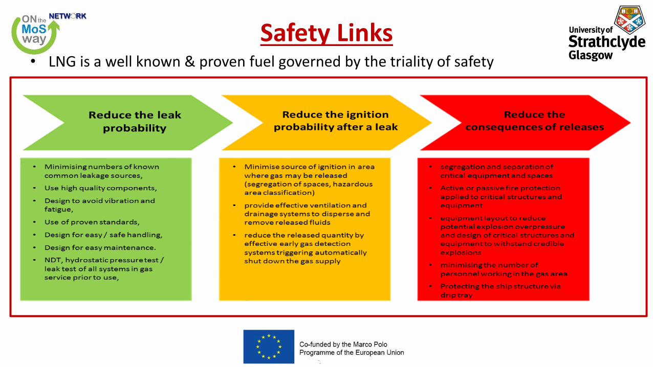
Safety Links• LNG is a well known & proven fuel governed by the triality of safety

Tank categorization
• Type A independent tanks are not essential to maintain hull strength andintegrity.
• Type B independent tanks are designed using refined analytical tools andanalysis methods to determine stress levels, fatigue life and crack propagationcharacteristics.
• Type C (cryogenic pressure vessels) are designed on the basis of recognizedcodes supplemented by IMO IGC code, statutory and class rules and regulations.
• Type C have been used for decades on on-shore applications. On ships primaryhazard is cryo-cracking following leakage.
• Type A & B are “atmospheric” tanks which are subject to “boil-off”. Type C tanksstore LNG at higher pressures with minimized BOG for long periods of time.Disadvantage is poor space utilization by C tanks. Overall C tanks have lowermaintenance costs.

Tank types
• Failure developments that can be reliably detected before reaching a critical state (e.g. by gasdetection or inspection) shall have a sufficiently long development time for remedial actions to betaken.
• Failure developments that cannot be safely detected before reaching a critical state shall have apredicted development time that is much longer than the expected lifetime of the tank.
• No secondary barrier is required for type C independent tanks, where the probability for structuralfailures and leakages through the primary barrier is extremely low and can be neglected.

4 types of LNG tanks

Tank types
Courtesy of Wartsila

Tank Type A

PERLITE TYPE
FOAM INSULATION
TYPE
Primary & Secondary Barriers
Type A tanks

IHI SPB
SYSTEM
KVAERNER MOSS
SYSTEM
1st and Partial 2nd Barriers
Type B tanks

Tank Design

Leak before break philosophy
• Cracks initiate from regions of high stress concentration or from defects, already present in thevessels, usually in welds.
• There are two possible modes of failure, depending on the load and the toughness of the material.
a)Crack grows steadily through the wall by fatigue to form a stable "through-crack“. "leak-before-break“ LBB
b) Crack becomes unstable before or after it has reached the rear surface and spreadsrapidly over a large portion of the vessel.
• In a) case there is a chance for damage to be detected or for the internal pressure to be relievedbefore sudden catastrophic failure of the vessel. LBB behavior is an important requirement for thesafe design and re-assessment of pressure vessels. LBB design gives sufficient warning before leadingto catastrophic failure of structures.

Development of LBB Criterion
• The fracture condition for a surface flaw is:
• Kct:fracture toughness
• p is the internal pressure
• R is the radius of vessel
• s is the wall thickness
• MKis the Kobayashi stress intensity magnification factor.
• θis an elliptical integral of the second kind
𝜃 = 0
𝜋2+ 1 −
𝑐2 − 𝑎2
𝑐2𝑠𝑖𝑛2𝜑 𝑑𝜑

Development of LBB Criterion cont’d
• It can be shown that for𝑎
𝑐→ 0 𝜃 =
3𝜋
8+𝜋𝑎2
8𝑐2
• Pressure p1 for unstable propagation:
• The stress intensity factor for a through-the-thickness crack of length 2c is given by:
• MF(λ) is the Folias correction for bulging , σ is the hoop stress, σ = p R/s
• Kcis the fracture toughness for crack growth in the axial direction
• Pressure p2, causing unstable propagation of the through crack:

Development of LBB Criterion cont’d
• The crack arrest may occur if the pressure to propagate the through crack of length 2c is larger than the pressure for instability of a flaw with depth a. Hence, the leak-before-break criterion follows from p2>p1 or
• For thin walled pressure vessels the R/s ratio is large and surface flaws are usually in the order of a few times the plate thickness. The resulting through crack has the same size, and since R/s is large, the Folias correction is still approximately MF ≈ 1. Then :
Stress intensity factor of the through-crack must be smaller than the critical one

Type A tank and supports
• Type A cargo tanks are self supporting tanks
designed using recognized ship structural
analysis procedures. They are gravity tanks made
of plane surface and their design vapor pressureis limited to a maximum of 0.7 bars.

Supports of cargo tank• Four rows of vertical supports in way of the transverse frame taking the weight of the tank
+ cargo to the hull. They sustain 400-1000 t. Corner ones are the more loaded.
• Anti-rolling keys, preventing lateral motion, are fitted along the center line, at the upper and
lower part of the cargo tank.
• Anti-pitching keys, preventing longitudinal motion, are located at mid span of the cargo
tank, at the lower part of the cargo hold. They are also serving as anti collision keys.
• Two rows of anti flotation keys, preventing lifting of the cargo tank in case of flooding,located on the top of the cargo tank on each side.

Independent Tank A

Type C tanks• Vacuum insulated tanks
• Two tanks one in each other : Inner vessel and outer vessel
• Space between the two tanks is filled with insulation material and kept under vacuum
• Excellent insulation properties

GTT Membrane Containment System
► metallic low-stressed primary barrier (corrugated stainless steel)
► composite secondarybarrier
► Two layers of insulation to protect the hull from the cargo low temperature

From the gas manifold to the engines

Engine room types• Gas safe machinery spaces are safe under all conditions. A single failure cannot lead to release of fuel
gas into the machinery space. All fuel piping within machinery space boundaries shall be doublewalled.
• ESD-protected machinery spaces are non-hazardous under normal conditions, but may becomehazardous. A single failure may result in a gas release into the space. Venting is designed for aleakage scenario. Failures such as gas pipe ruptures or blow out of gaskets are tackled by pressurerelief devices and shut-down arrangements.

Gas Safe Engine Room

Emergency Shut-down Engine Room

IMO Regulations & Existing Class Rules
► IMO started the development of the “International Code for GasFuelled Ships” (IGF code) in 2009.
► Name became: International Code of safety for ships using Gases or other low-flashpoint Fuels in order to
address some liquid fuels such as ethanol, methanol hydrogen & synthetic fuels.
► The code will be applicable to ships above 500GT. It will not be applicable to ships complying with IGC Codeeven in the case of gas carriers using low-flashpoint fuels other than their cargo
► Entry into force is expected in the first half of 2017.

Definitions• Fuel containment system is the fuel storage tank and tank connections.
• Fuel storage hold space is the space enclosed by the ship's structure in which a fuel
containment system is situated.
• Inter-barrier space is the space between a primary and a secondary barrier.
• Tank connection space is the space enclosing all tank connections and tank valves.
• Fuel preparation room: space containing pumps, compressors and/or vaporizers.

Location of spaces
• LNG fuel storage, transfer, process, distribution and use are to be such that the number and extent ofhazardous areas is minimized.
• Storage tanks, transfer and process systems may be located in the same space.
• Fuel preparation room is located on open deck, unless it is arranged and fitted with the regulationsof TCS.
• Tank Connection Space (TCS) cannot be located adjacent to machinery spaces of category A.
• If there is a cofferdam it must have a width of at least 900 mm and A-60 class insulation on E/R side.
• Fuel pipes shall not be located less than 800mm from the ship’s side.
• Bunkering stations must be located on open deck with sufficient natural ventilation.

Entrances and other openings (IGF Code §5.11)
• Direct access shall not be permitted from a non-hazardous space to a hazardous space.Where necessary utilize an airlock.
• If the fuel preparation room is located below deck, the room shall have an independentaccess directly from the open deck.
• Unless the access to the TCS is independent and directly from open deck, a bolted hatchmust be fitted. The space containing the bolted hatch is a hazardous space.
• For inerted spaces, access arrangements shall be such that unintended entry by personnelshall be prevented. If access to such spaces is not from open deck, sealing arrangementsshall ensure that leakages of inert gas to adjacent spaces are prevented.
Airlock (IGF Code §5.12)

Fuel supply redundancy IGF Code 9.3
• Fuel supply system shall have full redundancy and segregation all the way from the fuel tanks to theconsumer, so that a leakage in one system does not lead to a loss of power.
• For single fuel installations, the fuel storage shall be divided between 2 or more tanks. The tanks shallbe located in separate compartments.
• For type C tanks, one tank may be accepted if two completely separate TCS are installed for the onetank.

Fire protection• Any space containing pumps, compressors, heat exchangers,
vaporizers, pressure vessels is considered as machineryspace category A.
• A-60 class division must be fitted for accommodationsspaces, service spaces, control stations, escape routes andmachinery spaces facing the fuel tanks on open deck andextend up to the underside of the deck of the navigationbridge.
• A-0 class division for any boundaries above the navigationbridge, including bridge windows.
• The fuel containment system boundaries and ventilationtrunks to such spaces not located on open deck should beconstructed to class A-60 standard and cofferdam.
• For type C tanks, the hold space may be considered as acofferdam.
• If the adjacent room to tanks has low fire risk (voids,auxiliary machinery, sanitary) insulation standard may bereduced to A-0 w/o cofferdam.

Fire protection cont’d
• The bunkering station (IGF Code §11.3.6) must be separated by A-60bulkheads from machinery spaces of category A, accommodation,control stations and high fire risk spaces. A-0 class divisions can be usedadjacent to tanks, voids, auxiliary machinery spaces of little or no firerisk.
• The fuel pipes (IGF Code §11.3.5) led through ro-ro spaces shall besubject to special consideration by the Flag.
• If an ESD protected machinery spaces is separated by a single boundary,the boundary shall be of A-60 class .

Zone Classification
• Zone 0 is an area in which an explosive gas atmosphere or a flammable gas or vaporis present continuously or is present for long periods.
• Zone 1 is an area in which an explosive gas atmosphere or a flammable gas or vaporis likely to occur in normal operation.
• Zone 2 is an area in which an explosive gas atmosphere or a flammable gas or vaporis not likely to occur in normal operation and, if it does occur, is likely to do so onlyinfrequently and will exist for a short period only.

Hazardous area zone 0

Hazardous area zone 1

Hazardous area zone 1

Hazardous area zone 2
Boltedhatch

Ventilation – Non Sparking fans IGF 13.3.3
Impeller material :Q235A
Housing material : Q235B
→ any combination of ferrous (including austenitic stainless steel) impellers and housings with not less than 13 mm tip design clearance.

Ventilation • 13.4 Regulations for tank
connection space – 13.4.1 The tank connection space shall be provided
with an effective mechanical forced ventilationsystem of extraction type. A ventilation capacity of atleast 30 air changes per hour shall be provided. Therate of air changes may be reduced if other adequatemeans of explosion protection are installed. Theequivalence of alternative installations shall bedemonstrated by a risk assessment.
– 13.4.2 Approved automatic fail-safe fire dampers shallbe fitted in the ventilation trunk for tank connectionspace.

Ventilation
• 13.6 Regulations for fuel preparation room– Fuel preparation rooms, shall be fitted with effective
mechanical ventilation system of the under pressuretype, providing a ventilation capacity of at least 30 airchanges per hour.
– The number and power of the ventilation fans shall besuch that the capacity is not reduced by more than 50%,if a fan with a separate circuit from the mainswitchboard or emergency switchboard or a group offans with common circuit from the main switchboard oremergency switchboard, is inoperable.
– Ventilation systems for fuel preparation rooms, shall bein operation when pumps or compressors are working.

Temperature considerations- Filling limits
• For worldwide service, ambient temperatures shall be taken as 5°C for air and 0°C for seawater.Higher values may be accepted for ships operating in restricted areas and conversely, lower valuesmay be imposed by the Administration for ships trading to areas where lower temperatures areexpected during the winter months.
𝑳𝒐𝒂𝒅𝒊𝒏𝒈𝑳𝒊𝒎𝒊𝒕 = 𝑭𝒊𝒍𝒍𝒊𝒏𝒈𝑳𝒊𝒎𝒊𝒕𝝆 𝑹𝒆𝒇𝒆𝒓𝒆𝒏𝒄𝒆𝝆 @𝑳𝒐𝒂𝒅𝒊𝒏𝒈

‘Fatigue Assessment of Type A/B Tanks’

Fatigue assessment of vertical supports
Typical details subject to fatigue assessment Toes of main frames
Crossings of shell longitudinals with transverse webs
Knuckles between double bottom & hopper tank
Brackets in cargo tank
Supports and keys
Tank dome

Load Cases
► Coarse mesh model: The elements modeling the
supports are to be deleted if found in tension.
► The load cases are combined with external sea
conditions :
Crest of wave head sea
Through of wave beam sea
Maximum internal acceleration
Beam sea maximum pressure
Beam sea maximum acceleration.
► The loads take into account hull girder moment and shear
forces, wave pressure on the shell and the internal tankpressure due to the accelerations.

Method for calculationof the support stiffness.
Support stiffness to betaken into account inthe model with Cargotanks and hull structure
Structural Analysis

Fatigue of supports and keys
• Vertical supports
X
Y
Z
VeriSTAR
Ship : 00632P State : First state (28/10/98)Model : Hold 2-3-4- Full load - Homogeneous cargo (11/05/00)DSA Top Down : Support for fatigue

Anti-rolling key

Long term distribution of friction stress
Based on histogram for fatigue analysis
Change from static to dynamic
friction This spectrum is made of two
spectrums. The first one is made
taking into account the static
friction coefficient of the wooden
spacer, and the second one, the
dynamic friction coefficient.
static distribution
Dynamic distribution
At “p’ sliding starts

Analysis steps
• Step 1 : Calculate with supports merged (no sliding)
• Step 2 : Calculate the probability level of sliding,
• Step 3 : Calculate with supports in two parts (sliding)
• Step 4 : A combination of damages obtained in steps 1 and 3

Fatigue assessment of anti rolling keys
► The methodology is different between vertical supports and anti rollingkeys due to gap in the key.
►
►Due to this gap, the methodology includes the following steps►Step 1 : Calculation without anti upper rolling key to define to what
probability level there is contact between anti rolling keys,►Step 2 : Calculation with anti rolling key merged (contact)►Step 3 : A combination of damages obtained in steps 1 and 2

Hull-Cargo Tank Interaction

Allowable loads of bearing materials
Distribution of vertical forces at supports
Friction at supports
Vertical Support
Support Design

Support design
X
Y
Z
V1
X
Y
Z
V1L5C1
X
Y
Z
V1L4C1
Cargo Tank Hull Bottom Support
and Anti-Pitch Chock
Bottom Support
and Anti-Roll Chock
Transverse Direction
Longitudinal Direction

Variation of Load on Supports
64
Balanced loads
Net upward load Net downward load

65
Critical areas
X
Y
Z
V1
G10
Typical Web Frame
(Hull Structure)
X
Y
Z
V1
G11
Typical Web Frame
(Cargo Tank)
X
Y
Z
V1
G9
Swash Bulkhead
(Cargo Tank)
XY
Z
V1
G12
Horizontal Stringer
(Cargo Tank)

Accurate Fatigue predictions are difficult to make.
• “The Good Lord watches over:
1) Children
2) Fools
3) People that try to predict fatigue failures
of LNG tank geometries with FEA programs.”
Analysis doesn’t mean anything in a poor weld.

‘Design & Analysis ofSaddle Supported Pressure Vessels’

Courtesy of Wartsila

Design of a pressure vessel
• Determine:
• Buckling resistance (local-global)
• Impact resistance
• Operating pressure & temperature ranges
• Maximum Allowable Working Pressure. It is based on the weakest element of the system exclusive of corrosion allowances.
• Residual stress (following thermo-mechanical treatment)
• If t/d is greater than 1/20 we have a thick cylinder.
• Required/rule thickness
• Nominal thickness/commercially available
• Design thickness = Required + Corrosion Allowance

Stresses in Pressure Vessels
• Circumferential/hoop stress acting tangentially to the circumference.• Longitudinal stress acting normal to the circumference.• Bending stress• Shear stress acting perpendicularly to the internal surface (radially)
• Moment of inertia of a thin shell I = p r3 t• Design Codes which apply:
– ASME Section VIII– EN 13458-2 – AS 1210– British standard BS 5500– IBR (Indian Boiler Regulation)– IGF Code– USCG Equivalency Determination CG-521
Policy Letter No 01-12, 19-4-2012

Design Steps
• Material selection• Thickness calculation• MAWP determination• Minimum design temperature• Weight calculation• Saddle calculations• Saddle stress analysis• Stiffener ring stress analysis• Lifting lug calculations• Nozzle/dome calculations• Required dome thickness
• Reinforcement pad
• Load calculations

Design Calculations• Shell and head thickness calculations are the fundamental calculations.
• Stress Analysis
• Buckling Analysis
• Fatigue Analysis
• Vibration Analysis
• Thermal Analysis
• Tank design life = Ship design life
• MAWP ≤ 0.9 MARVS &less than 10 bar in enclosed spaces
• Class rule: Design pressure = P vapor+ P hydrostatic + P inertia
• Vapor pressure is always taken equal to MARVS. If there is no temperature control (pressureregulated by ambient temperature) consider reference temperature = 45 o C
• Filling limit of 98% at reference temperature (45 o or max to be encountered or relief valvesetting). Avoid BOG venting (methane slip). Create a filling limit curve for various loadingtemperatures/pressures.
MARVS: Maximum Allowable Relief Valve SettingMAWP : Maximum Allowable Working Pressure

Internal Pressure
• The vapor pressure used in the design is generally to be taken as given in the specification, and not be taken less than the maximum allowable relief valve setting (MARVS):
• sm = Design primary membrane stress, to be taken equal to :
• Dsa = Allowable dynamic membrane stress (double amplitude at probability level Q = 10-8)
• = 55 N/mm2 for ferritic-perlitic, martensitic and austenitic steels
• C = Characteristic tank dimension, taken as the greatest of the following: h, 0.75 b, or 0.45 l (hxbxl)
• r = Relative density of the cargo at the reference temperature

Internal Pressure
• For fuel tanks with no temperature control po shall not be less than thevapor pressure at 45°C except :
i) Lower or higher values of temperature may be accepted by theR.O. in operations in defined areas.
ii) po can also be calculated based on pressure rise during thevoyage.
Pressure P is calculated as follows:P = Po+(Pgd)maxWith internal liquid pressure pgd resulting from combined effects of gravityand dynamic accelerations shall be calculated as follows:
αβ = dimensionless acceleration (i.e. relative to the acceleration of gravity),resulting from gravitational and dynamic loads, in an arbitrary direction β.Zβ = largest liquid height (m) above the point where the pressure is to bedetermined measured from the tank shell in the b direction
(𝑝𝑔𝑑)𝑚𝑎𝑥=𝛼𝛽𝑍𝛽𝜌
1.02 105

DNV-GL Design of Type C Tanks CN31.13
𝑒 = 1c = 0 or 1

Beware of structural discontinuities
• Wherever there are changes in geometry of a thin pressure vessel shell, such as between a cylindricalsection and a dome end, the 'incompatibility' of displacements caused by pressure loading in thesections gives rise to significant local (longitudinal) bending.
• The radial deformations of the shell and the dome are different, so are reacted by internal shearforces (Q) and moments (M). Shear stress produces inward bending of the shell, resulting incompressive circumferential strain, and tensile longitudinal strain.

Collision Considerations

Piping
• Pipe connections to the fuel storage tank shall be mounted above the highest liquid level in thetanks, except for fuel storage tanks of Type C.
• If connections are located in gas tight spaces, connections can be below maximum liquid level.
• Connections for purging, emptying, venting.
• Piping between the tank and the first valve which release liquid in case of pipe failure shall haveequivalent safety as the type C tank
• The material of the bulkheads of the tank connection space shall have a design temperaturecorresponding with the lowest temperature it can be subject to in a probable maximum leakagescenario.
• Secondary barrier pipe in double pipes must also enclose the welds around the connection nozzleson the tanks These welds are not NDTed internally (surface check). Specify UT.

Design of secondary barriers
• Where the LNG temperature at atmospheric pressure is not below minus 55°C, the hull structuremay be designed as a secondary barrier .
• The design of the secondary barrier, including spray shield if fitted, shall be such that:
1 It can contain a leakage of LNG fuel for 15 days.
2 Physical, mechanical or operational events within the LNG tank that could cause failure of theprimary barrier shall not impair the secondary barrier.
3 Failure of a support or an attachment to the hull structure will not lead to loss of liquidtightness of both the primary and secondary barriers.
4 It is capable of being periodically checked for its effectiveness by means of a visual inspection.
• The secondary barrier shall fulfill its functional requirements at a static angle of heel of 30°.

Partial secondary barriers
• Partial secondary barriers shall be a small leak protection system
• The partial secondary barrier shall include means to detect a leak in the primary barrier like a sprayshield to deflect any liquefied gas fuel down into the partial barrier and means to dispose of theliquid (e.g. natural evaporation).
• The capacity of the partial secondary barrier shall be determined, based on the leakagecorresponding to the extent of failure resulting from the design load spectrum after the initialdetection of a primary leak.
• Account may be taken of liquid evaporation, rate of leakage, pumping capacity.
• Leakage detection may be by means of liquid sensors, or by an effective use of pressure, temperatureor gas detection systems, or any combination thereof.
• Independent tanks for which the geometry does not present obvious locations for leakage to collect,the partial secondary barrier shall also fulfill its functional requirements at a nominal static angle oftrim.
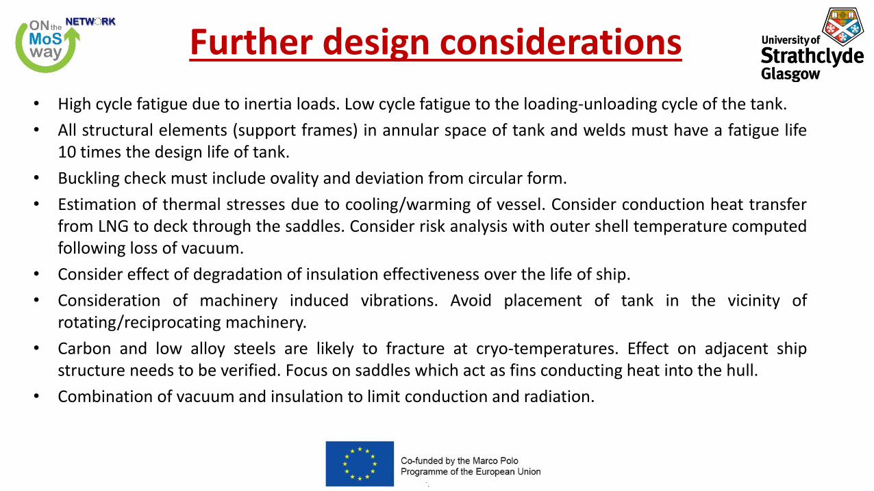
Further design considerations
• High cycle fatigue due to inertia loads. Low cycle fatigue to the loading-unloading cycle of the tank.
• All structural elements (support frames) in annular space of tank and welds must have a fatigue life10 times the design life of tank.
• Buckling check must include ovality and deviation from circular form.
• Estimation of thermal stresses due to cooling/warming of vessel. Consider conduction heat transferfrom LNG to deck through the saddles. Consider risk analysis with outer shell temperature computedfollowing loss of vacuum.
• Consider effect of degradation of insulation effectiveness over the life of ship.
• Consideration of machinery induced vibrations. Avoid placement of tank in the vicinity ofrotating/reciprocating machinery.
• Carbon and low alloy steels are likely to fracture at cryo-temperatures. Effect on adjacent shipstructure needs to be verified. Focus on saddles which act as fins conducting heat into the hull.
• Combination of vacuum and insulation to limit conduction and radiation.

Tanks installed below accommodation
• Protection against external damage (collision/grounding/fire/mechanical damage).Preferably number of tanks needs to be increased against economy of scale.
• Installation must include gas detectors, alarms, shut-downs, negative pressureventilation of not less than 30 air changes per hour, liquid level monitoring in bilges.Space is Zone 1 so it will need safe certified electrical equipment. Bulkheads anddecks must be thermally insulated (A-60 class).
• Risk analysis assessment needs to be performed. Scenario of over-pressurizationdue to fire in an adjacent compartment, fire/explosion due to LNG leakage, loss ofhull structural integrity.

Fabrication & Testing
• Need material trace-ability for tank material. Mill certificates.
• Documentation of mechanical/chemical properties.
• Tests must be witnessed by class surveyor.
• Welder qualifications-Full penetration welds. 100% NDT on nozzles, reinforcement pads.
• Corrosion allowance not needed since LNG is non-corrosive. Tank external surface is protected byinsulation.
• The tolerances for out-of-roundness, local deviation from true circular form, weld joint alignmentand tapering of plates having different thicknesses are to be in accordance with the requirements ofthe applicable pressure vessel code.
• Marking of the tank is required to be accomplished by methods (such as the use of low stress tamps)that do not cause local stress raisers on the tank.
• Type C LNG tanks of carbon-manganese steel are required to be stress relieved by post-weld heat treatment. For large tanks mechanical stress relieving by pressurization is an acceptable alternative.

Fabrication & Testing cont’d• For mechanical stress relieving, the prototype tank would need to be strain gauged in order to verify
that at the end of the stress relieving process a linear relationship exists between pressure andstrain.
• Steels with a ratio of yield strength to ultimate strength exceeding 0.8 should not be mechanicallystress relieved since the material does not possess sufficient ductility.
• Tank must be hydrostatically pressure tested to not less than 1.5 times the design vapor pressure.Test pressure is to be maintained for at least 2 hours per 25 mm of tank thickness, but in no case lessthan 2 hours.
• Verify that under hydrostatic test pressure conditions, calculated primary membrane stresses do not exceed 90% of the yield strength of the materials.
• If calculated primary membrane stresses exceed 0.75 times the yield strength, at least one prototype tank and its supports would be required to be strain gauged in order to monitor the stresses during the testing.
• After complete assembly of the tank and installation of all the tank fittings, the tank would be required to be leak tested to the MAWP.

Critical inspection areas
• For vacuum insulated Type C LNG tanks, the inner tank as well as the annular space(between the inner tank and the outer vacuum jacket) are typically not accessiblefor inspection
• A detailed in-service inspection plan is essential. This plan is intended to reliablydetect potential failures before they reach a critical state.
• Failures in uninspectable areas of tanks could typically be caused by corrosion,leakage or fatigue. Leakage is checked periodically by conducting a helium leak testof the inner tank.
• Damage to the insulation or loss of vacuum would manifest itself as an increase in the boil off rate

Differences between A, B, C tanks• Type B tanks are free-standing tanks that are designed under a
leak before break criteria. They only require a partialsecondary barrier.
• B tanks are available in both prismatic and spherical shapes.
• Type C tanks are based on recognized pressure vesselstandards and require no secondary barrier.
• Type A tanks, being prismatic in shape provide goodvolumetric fit to hull structure for cargo tankage, as domembrane and prismatic type B tanks.
• Use of elliptical or tori-spherical heads provides a slightincrease in tank volume for the same overall length of thecargo tank improving volumetric efficiency slightly. A depth todiameter ratio of 2:1 is provided under the ASME pressurevessel code. There is a thickness penalty to the use of thealternate head shapes.

Material choices
• 5086 Aluminum - 304 stainless steel - 9% nickel steel
• Recent designs utilize 304 stainless steel.
• According to IGC code minimum design pressures are : 304 SS P=2.7 bar, 9% Nickel Steel P=4.3 bar, 5083 Aluminum P=3.6 bar
• Design for maintainability
• A method to get the liquid into the tank
• A means to get the liquid out of the tank.
• A method to get excess gas out of the tank.
• Instrumentation to find out what’s happening.
• Top and bottom fill lines if pressure needs to be constant during fill. Top filling lowers pressure. Bottom filling raises pressure.

Two or three saddle supports• Two supports or saddles should support horizontal
pressure vessels longitudinally. This is to preventtransfer of bending moments and hull deflectionsresulting from still water and WBM.
• A greater number of supports / saddles can beconsidered.
• Increasing the number of saddles will allow forreduced shell thickness, but consideration must begiven to localized bending moment increasesresulting from the loading and unloading of thesaddles resulting from hull bending.
• Saddles must be configured to accommodate tankshrinkage when in the cold condition and toprovide restrained motion in the transverse andlongitudinal directions. The tank must also berestrained in the vertical direction to prevent thetank from floating in the case of a hull breach.

Insulation System• Insulation system controls the achieved boil-off rate.
• It remains to be seen if vacuum insulation is practical or necessary.
• A perlite filled hold space though is not consider an acceptableinsulation system due to access blockage for inspection or repairs.
• Rigid foams of various compositions are the preferred choice.Flammability of PU though raises safety concerns. Allegedly an LNGpool fire resulting due to breach of a single tank will cascade aseries of fires on the remaining tanks.
• “Aero-gel” technology provides an insulation which reduces boil-offrate, but also provides fire protection equivalent to an A-60bulkhead. Low density aero-gels are manufactured by extracting theliquid component of a gel and replacing it with gas.
• Aero-gel blankets are thermally 2 to 3 times more efficient thancompeting insulating materials.

Radiation shields
• Without shield (assuming same emissivity e)
𝑄12 =𝐴𝜎(𝑇2
4 − 𝑇14)
2𝜀− 1
• With one shield
𝑄′12= 𝐴𝜎(𝑇2
4−𝑇14)
2
𝜀−1+
1
𝜀−1+
1
𝜀−1

Features of the Geometry
• Saddles with or without wear plates
• Wear plate attached to shell on outer edge by fillet weld
• Support members welded only to wear plate – not directly to shell
• Trends are dominated by the ratio t wear plate/t shell

FEA analysis of supports
• Finite Element Analysis can evaluate geometries and loads when no other solutions are possible.
• External Loads (sloshing, wind, seismic, piping induced thermal)
• Fatigue Analysis
• Multiple Saddles
• Ovalization effect
• Influence of Pressure on Circumferential Bending

Weight (Zick-Type) Stress Trends at Saddles
• Highest stress usually at saddle horn (Compressive on Outside)
• Vessel length, diameter, and thickness will influence shift of stresses the vessel MUST be allowed toovalize if there are no stiffening rings.

Saddle Design Guidance
• Flexible wear plate reduces stresses inshell BUT may increase the stress in thewear plate. Optimize the design bybalancing the stress in shell and the wearplate.
• Wear plates are NOT always required. Using FEA analysis it can be quickly determined if there is need for wear plates.
• Wear plate thickness is typically selected equal to shell thickness. FEA shows that optimum designs can be between 0.5 < t/T < 1.25
• Saddle angles are between 120 and 150 degrees.

Saddle model

Saddle supports
• Saddle supports are commonly used to support Horizontal pressure vessels
• Optimized designs parameters reduce the material cost.

Optimum when M1=M1’
• Bending moment at saddle
• Bending moment at mid-span

Longitudinal Stress
• Resultant axial stress due to bending and pressure will be given by:
• The ends of the vessels will stiffen the shell if the position of the saddles is less than D/4 from the ends. Ring stiffeners, located at the supports, are used to stiffen the shells of long thin vessels. The rings may be fitted inside or outside the vessel.

Design of saddles 1

Design of saddles 2

Pressure vessels vs storage vessels
• Pressure vessels contain fluids, vapors or gases at pressures greater than atmospheric. Storagevessels/tanks are used for storing liquids, solutions or pharmaceutical raw material and otherchemicals.
• Potential hazards include: operating the vessels above their design limits, fatigue failure due torepeated pressurization, thinning of the vessel wall due to corrosion, stress corrosion crackingembrittlement, holes and leaks, improper repair of a leak or a weld defect.

Vessel Head Shapes
• Hemispherical Head
• Ellipsoidal Head (2:1)
• Torispherical Head
• Klopper head: A torispherical head with a dish radius equal to the diameter of the cylinder it is attached to ( r1 = Do ). The knuckle has a radius that equals a tenth of the diameter of the cylinder (r2 = 0.1 Do).

DIN Vessel Standards
• DIN EN 13445 covers the design and fabrication of unfired pressure vessels.
• An array of differing national regulations, standards, and codes for pressure vesselshas been replaced by a single European directive.
• Stainless steel is recommended to be used in vacuum applications, because at highvacuum SS304 does not oxidize.
• Stainless steel of composition 18/8 (18% Chrome and 8% Nickel) is the best optionfor cryogenic and vacuum applications.
• A thin film is formed on the surface of any alloy with chrome composition more than13%. It is impermeable to corrosive media and it renews itself in the presence ofoxidizing agents. Nickel is used to improve the corrosion resistance and to maintainthe austenitic structure of steel. Nickel also helps in improving weldability andductility of steel.

Stainless steel used in vacuum equipment
• Arrows point out in the direction of improved properties
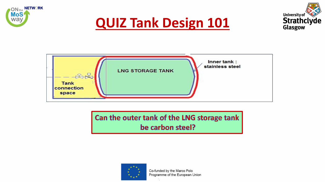
QUIZ Tank Design 101

Saddle position
• As a rule, the saddles should be positioned at a length not more than the radius of the vessel.
• To obtain stiffening effect from the head or cover plates, the saddle should be kept at length notmore than 20% of the total length.

Stiffening ring
• The required moment of inertia of a circumferential stiffening ring can be calculated by procedureUG-28 of ASME Boiler and Pressure Vessel Code (BPVC), Section VIII, Division I.
• Select a section to be used for the stiffening ring and find its cross sectional area “As” .
• Find factor B, where Do outside tank diameter and Ls ring span.
• Find the value of factor “A”. E= Young’s modulus
• Required moment of inertia of the stiffening ring

LNG Tank & Vaporizer
Courtesy of Wartsila

Pressure Build-Up PBU
• Waste heat from the vessel’s engines is rejected in the Vaporizer through the water glycol circuit.
• A to B pressure changes due to height difference
• B to C temperature rises from sub-cooled (-163 deg) to saturated @ P
• C to D LNG vaporized and superheated
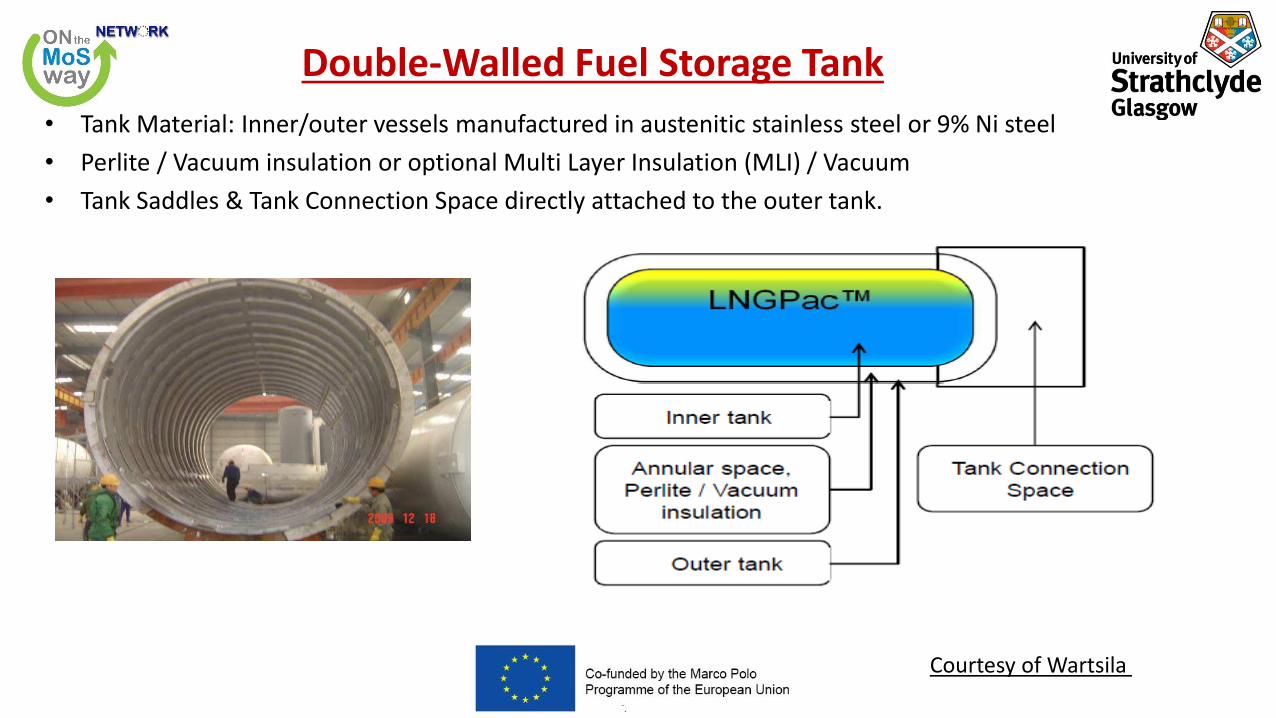
Double-Walled Fuel Storage Tank
• Tank Material: Inner/outer vessels manufactured in austenitic stainless steel or 9% Ni steel
• Perlite / Vacuum insulation or optional Multi Layer Insulation (MLI) / Vacuum
• Tank Saddles & Tank Connection Space directly attached to the outer tank.
Courtesy of Wartsila

Fuel System
Courtesy of Wartsila

Single-Walled Fuel Storage Tank
• Galvanized sheet steel, GRP or SS316 cladding is the material of the secondary barrier.
• Capacities from 300 – 2500 m3.
• Dome on top of Tank for all tank pipe connections above maximum liquid level.
• Tank Connection Space separated from Tank

With Pump configuration- No PBU
• Lower pressure for both 2-X and 4-X
• Higher maintenance cost
• Rotating equipment- Lower reliability
Courtesy of Wartsila

With PBU
• Self regulating- No rotating equipment
• High reliability
• Low maintenance cost
• Higher design pressure
• Only for 4-X engines
Courtesy of Wartsila

Double-Walled Fuel Storage Tank
• 8.5-9.0 bar, pressure built-up system (pump configuration is also possible)
• 30-1000m3
• Expensive
• Lower volume to weight ratio
• Higher holding time
• Limitation in diameter of outer shell, suitable only for volumes below 1000 cubic meters
• Advanced supports between inner and outer tank, full pipe stress analyses of piping in annular space, special bottom pipe/valve arrangement
• HORIZONTAL & VERTICAL
• IGF compliant, excellent insulation medium. For smaller tank diameters more critical
• PBU system, no rotating equipment.

Single-Walled Fuel Storage Tank
• 4.0 to 6.0 bar , pump configuration
• Higher volume to weight ratio
• Higher diameters can be fabricated
• Easier pipe connections
• Bottom penetration not accepted without secondary barrier
• Not suitable for below deck installations
• Cheaper
• Lower holding time
• 700-2500m 3
• Saddle construction, special transport saddle
• Thicker insulation, as polyurethane is worst insulator
• BILOBE
• For larger tank diameters large volume/surface ratio
• Tank pipe connections @ DOME, always on top of thetank, requires more available height

Fuel System

Design considerations on tank location
• Tank space is a challenge for designers to reduce loss of cargo space
• Relatively easy for tanker/chemical or gas carrier on open deck
• Small container feeder: first bay in front of bridge loosing cargo space
• Medium size container vessel: open deck aft of accommodation or first bay
• Large container vessel (two island): below accommodation block
• Ferry/cruise liner: below deck following B/5 restriction
• RoRo/RoPax: mobile tanks, especially for retrofits

Vacuum tank with “cold box”

LNG fuel gas systems – two stroke engines

Inner pipe design criteria
• Design Pressure 320 bar
• Test Pressure 480 bar
• Temperature -55 oC to +60oC
• Total Pressure loss (max) 5 bar
• Piping should be cold worked in order to reduce internal surface roughness.
• Maximum surface roughness, Ra 15μm
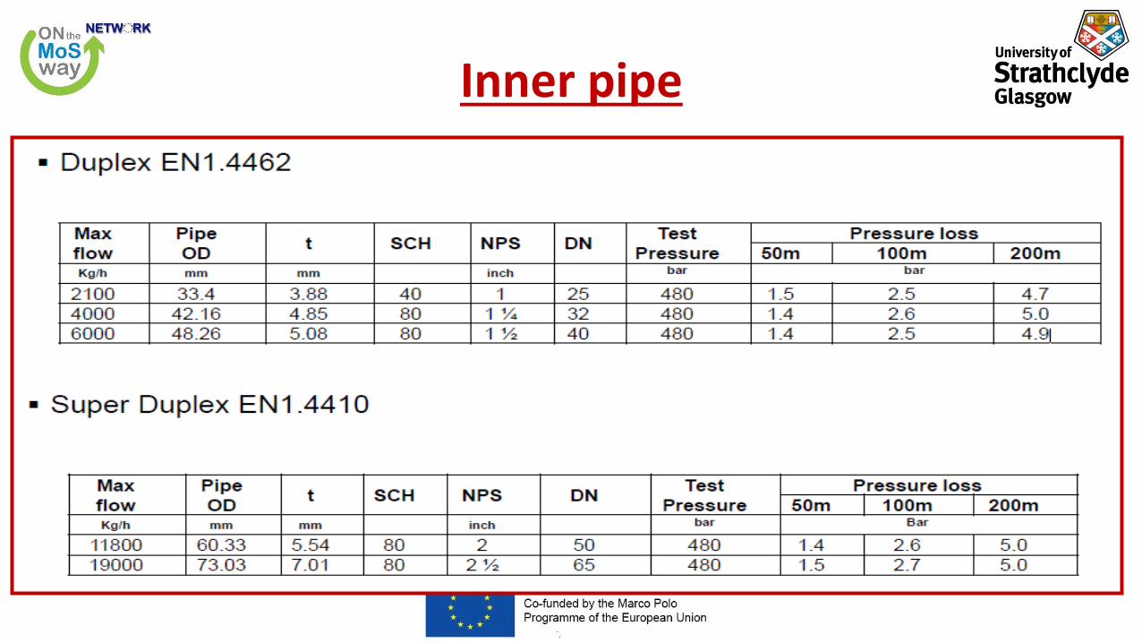
Inner pipe

Outer pipe design criteria
• IGF code, chapter 9.8:
The tangential membrane stress of a straight pipe should not exceed the tensile strength divided by1.5 (Rm/1.5) when subjected to the critical pressure. The pressure ratings of all other pipingcomponents should reflect the same level of strength as straight pipes.

Supply pipe
• Inner pipe: Stainless steel Ø48x5
• Outer pipe: Stainless steel
• As few welds on inner pipe as possible
• Spring supports to be fitted on inner pipes.
Courtesy MAN-BW

Fuel Gas supply pipe
Courtesy MAN-BW
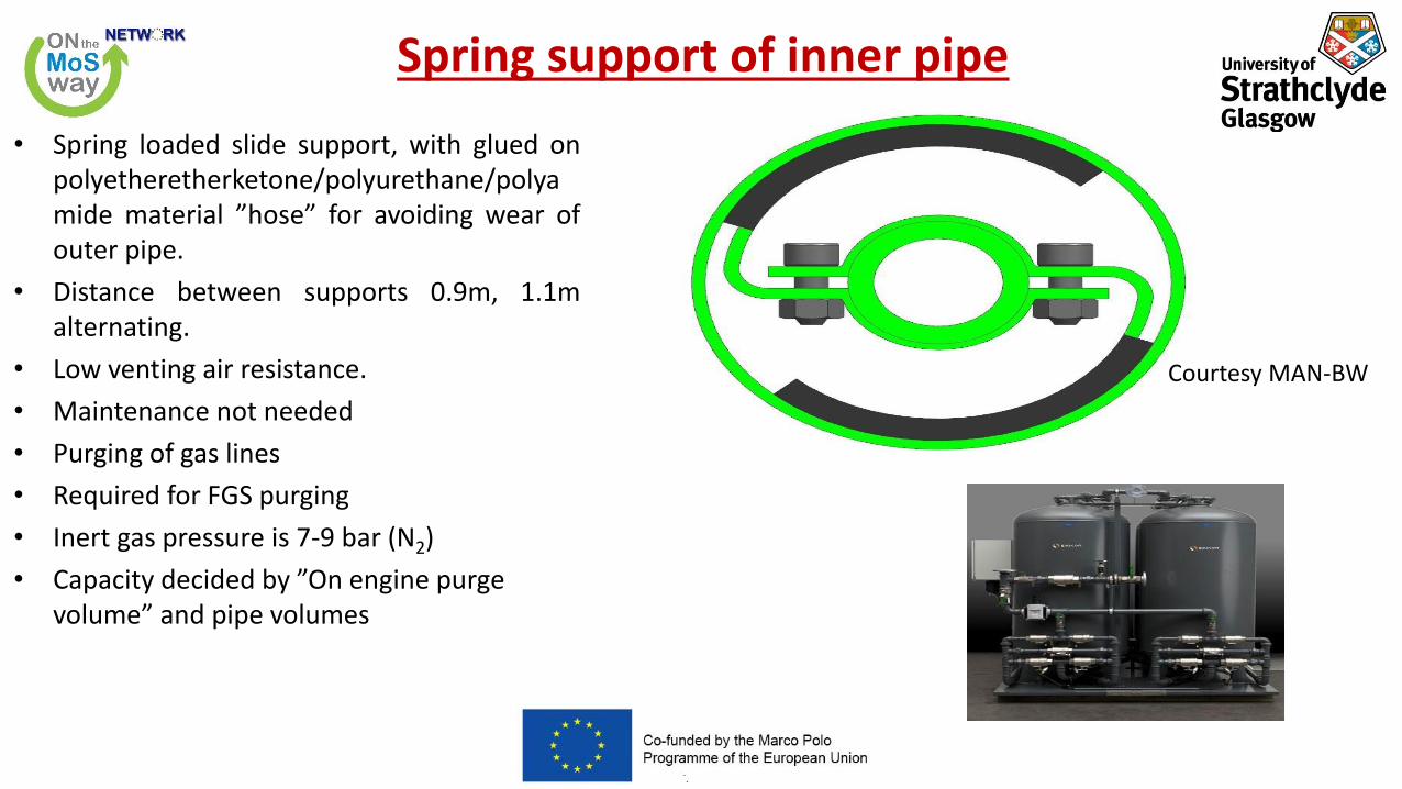
Spring support of inner pipe
• Spring loaded slide support, with glued onpolyetheretherketone/polyurethane/polyamide material ”hose” for avoiding wear ofouter pipe.
• Distance between supports 0.9m, 1.1malternating.
• Low venting air resistance.
• Maintenance not needed
• Purging of gas lines
• Required for FGS purging
• Inert gas pressure is 7-9 bar (N2)
• Capacity decided by ”On engine purge volume” and pipe volumes
Courtesy MAN-BW

Location & protection of fuel piping
• Gas pipes shall not be located less than 760 mm from the ship's side.
• Gas fuel piping, whether single or double walled, shall not be led directly throughaccommodation spaces, service spaces, electrical equipment rooms or controlstations unless the gas piping is double walled and led through a dedicated duct.
• The routing of the piping shall take into account potential hazards due to mechanicaldamage.
• Gas fuel piping in ESD protected machinery spaces shall be located as far aspracticable from the electrical installations and tanks containing flammable liquids.

Machinery space design
• ESD protected machinery spaces separated by a single bulkhead shall have sufficient strength towithstand the effects of a local gas explosion in either space, without affecting the integrity of theadjacent space and its equipment.
• ESD protected machinery spaces shall be designed to provide a geometrical shape that will minimizethe accumulation of gases or formation of gas pockets.
• Fuel preparation rooms or Compressor rooms if arranged, shall be located on an open deck, unlessthose rooms are arranged and fitted in accordance with the requirements of this Code for tankconnection spaces.

Entrances and other openings
• Direct access shall not be permitted from a non-hazardous space to a hazardous space. Where suchopenings are necessary for operational reasons, an air lock shall be provided.
• If the fuel preparation room is below deck, the room shall have an access from the open deckotherwise through an air lock.
• If the access to an ESD-protected machinery space is from another enclosed space in the ship, theentrances shall be arranged with an air lock
• For inerted spaces access arrangements shall be such that unintended entry by personnel shall beprevented. If access to such spaces is not from open deck, sealing arrangements shall ensure thatleakages of inert gas to adjacent spaces are prevented.

Requirements for air locks
• An air lock is a space enclosed by gastight/steel bulkheads with two gastight doors spaced at least 1.5m and not more than 2.5 m apart. The door sill shall not be less than 300 mm in height. The doorsshall be self-closing without any holding back arrangements.
• Air locks shall be mechanically ventilated at an overpressure relative to the adjacent hazardous areaor space. Audible and visual alarms shall be given at a manned location to indicate both loss ofpressure and opening of the airlock doors when pressure is lost. They shall provide free and easypassage, and shall have a deck area not less than 1.5 m2.
• An audible and visual alarm system to give a warning on both sides of the air lock shall be providedto indicate if more than one door is moved from the closed position.
• Essential equipment required for safety shall not be de-energized and shall be of a certified safe type.This may include lighting, fire detection, public address, general alarms systems.
• Electrical equipment which is not of the certified safe type for propulsion, power generation,manouvring, anchoring and mooring equipment as well as the emergency fire pumps shall not belocated in spaces to be protected by air-locks.

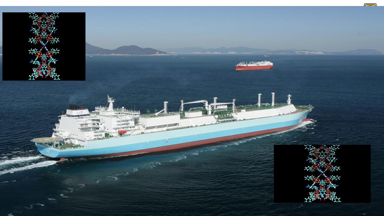
How to solve the problem of gas storage?
Metal Organic Frameworks

Gas Storage Capacity of MOF Materials• The surface area of one gram of MOF could cover up to forty tennis courts.
• There is a great number of locations for gas molecules to "stick" or adsorb to. Once these molecules areadsorbed and immobilized on the material, they take up less space.
• A tank filled with MOF material can store much more gas than an empty tank. Gas can be released bysimply opening a valve on the tank.