Embed Size (px)
Citation preview
1
LNG PUMPS FOR FLOATING UNITS
Fabien Wahl Nikkiso Cryo Inc.
4661 Eaker Street North Las Vegas, Nevada, 89081, USA
Tel: +1 702 643 4900 Fax: +1 702 643 0391
[email protected] http://www.nikkisocryo.com
ABSTRACT
Lower capital costs, shorter on-stream time, lower coastal environment impact, flexibility — these are some reasons that led to the development of the FPSO and FSRU. Because the FPSO or FSRU is subjected to the vertical and lateral accelerations of the vessel while underway in addition to the accelerations when at its mooring location, it experiences a more severe exposure to motions. The challenges to beat were to develop machinery, components and systems that would perform during and after exposure to these differing levels of the motion of the ocean. In order to participate to the reduction of the capital investment and the operating costs, top level technologies answering the requirements of equipment compaction, low NPSHR, high efficiency, high MTBF have been successfully developed, and will bring LNG pumping to a new era of excellence.
1 INTRODUCTION
Lower capital costs, shorter on-stream time, lower coastal environment impact, flexibility… these are some reasons that led to the development of the Floating Storage and Regasification Unit, (FSRU) and Floating Production Storage and Offloading (FPSO) units. Typically these units are like large barges that are semi permanently moored offshore and are filled or emptied by standard LNG Carriers (LNGC). A special subset of the FSRU concept is the LNG Carrier that is fitted with a full regasification capability and can first transport LNG from a liquefaction plant to a delivery site and second regasify this LNG off-shore. These special vessels are labeled as LNG Shuttle and Regasification Vessels or SRVs.
Because the SRV is subjected to the vertical and lateral accelerations of the vessel while underway in addition to the accelerations when at its mooring location, it experiences a more severe exposure to motions. In order to put a regasification unit on board a floating and seagoing vessel, the challenge was to develop machinery, components and systems that would perform during and after exposure to these differing levels of the motion of the ocean. Along the various stage of the SRV rotation, the pumps on board the vessel are submitted to a different spectrum of accelerations, as shown in Table 1.
Table 1. Operation environment
Accelerations [G]
Regasification Operation
Transit Seagoing
Vertical 0.4 0.8
Transversal 0.2 0.5
Longitudinal 0.1 0.6
2
2 LNG PUMPS FOR SRV
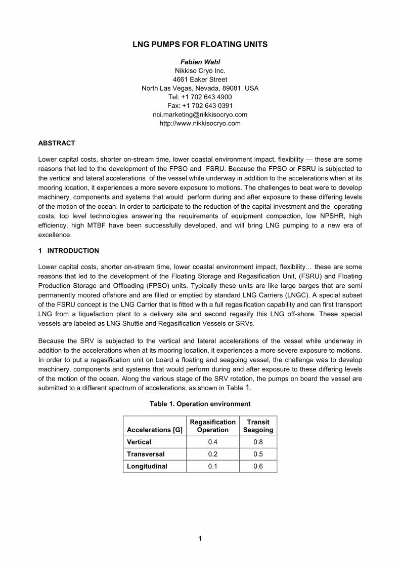
Figure 1 shows the Nikkiso Cryo Regasification ship pump set which is used on board the Excelerate Energy fleet of vessels since 2004. Standing on the left, there is the emergency/in-tank pump which on an SRV vessel must perform the duty of being the primary feeder to the deck mounted high pressure send out and to the line packing pump. Lying on the Horizontal Assembly Stand ©, there is the send out pump. Standing on the far right, there is the line packing pump.
Figure 1. Nikkiso Cryo Regasification ship set
The in-tank pumps are located inside the emergency wells found on a traditional LNG carrier. Unlike the original emergency pumps of a classical ship set, these primary pumps are permanently lowered in the column. These pumps feed the suction drum, and are rated for a flow of 620m3/h, with a differential head of 115m. The pump rated power is 200kW.
The send out pumps are located on the bow of the ship. They are mounted in their own suction vessel, themselves integrated onto skids. These pumps feed the vaporizers at a flow of 205m3/h, and with a differential head of 2370m. The pump rated power is 1100kW.
Line packing pumps are operated during the start-up of the re-gasification unit to pressurize the vaporizers and the downstream pipeline smoothly without liquid hammer. These 200 kW pumps deliver the same differential head as the send-out pumps (2370 m), but at a lower flow rate (20 m3/h). The line packing pumps are vessel mounted on the bow of the ship along with the send-out pumps..
For more recent projects such as Golar - Winter and Hoegh LNG – Neptune, larger send out pumps have been developed, reaching 15 stages and 1500kW.
3
3 TECHNICAL CHALLENGES
3.1 In-tank pumps
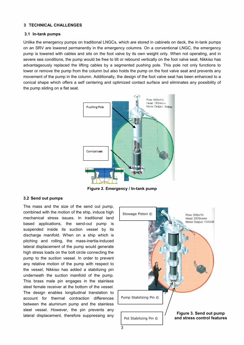
Unlike the emergency pumps on traditional LNGCs, which are stored in cabinets on deck, the in-tank pumps on an SRV are lowered permanently in the emergency columns. On a conventional LNGC, the emergency pump is lowered with cables and sits on the foot valve by its own weight only. When not operating, and in severe sea conditions, the pump would be free to tilt or rebound vertically on the foot valve seat. Nikkiso has advantageously replaced the lifting cables by a segmented pushing pole. This pole not only functions to lower or remove the pump from the column but also holds the pump on the foot valve seat and prevents any movement of the pump in the column. Additionally, the design of the foot valve seat has been enhanced to a conical shape which offers a self centering and optimized contact surface and eliminates any possibility of the pump sliding on a flat seat.
Figure 2. Emergency / In-tank pump
3.2 Send out pumps
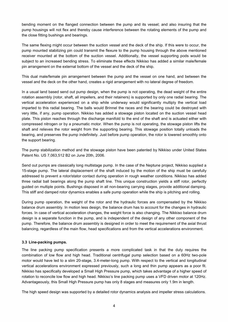
The mass and the size of the send out pump, combined with the motion of the ship, induce high mechanical stress issues. In traditional land based applications, the send-out pump is suspended inside its suction vessel by its discharge manifold. When on a ship which is pitching and rolling, the mass-inertia-induced lateral displacement of the pump would generate high stress loads on the bolt circle connecting the pump to the suction vessel. In order to prevent any relative motion of the pump with respect to the vessel, Nikkiso has added a stabilizing pin underneath the suction manifold of the pump. This brass male pin engages in the stainless steel female receiver at the bottom of the vessel. The design enables longitudinal translation to account for thermal contraction differences between the aluminum pump and the stainless steel vessel. However, the pin prevents any lateral displacement, therefore suppressing any
Pump Stabilizing Pin ©
Pot Stabilizing Pin ©
Stowage Piston ©
Figure 3. Send out pump and stress control features
4
bending moment on the flanged connection between the pump and its vessel; and also insuring that the pump housings will not flex and thereby cause interference between the rotating elements of the pump and the close fitting bushings and bearings.
The same flexing might occur between the suction vessel and the deck of the ship. If this were to occur, the pump mounted stabilizing pin could transmit the flexure to the pump housing through the above mentioned receiver mounted at the bottom of the suction vessel. Additionally, the vessel supporting pods would be subject to an increased bending stress. To eliminate these effects Nikkiso has added a similar male/female pin arrangement on the external bottom of the vessel and the deck of the ship.
This dual male/female pin arrangement between the pump and the vessel on one hand, and between the vessel and the deck on the other hand, creates a rigid arrangement with no lateral degree of freedom.
In a usual land based send out pump design, when the pump is not operating, the dead weight of the entire rotation assembly (rotor, shaft, all impellers, and their retainers) is supported by only one radial bearing. The vertical acceleration experienced on a ship while underway would significantly multiply the vertical load imparted to this radial bearing. The balls would Brinnel the races and the bearing could be destroyed with very little, if any, pump operation. Nikkiso has added a stowage piston located on the suction vessel head plate. This piston reaches through the discharge manifold to the end of the shaft and is actuated either with compressed nitrogen or by a pneumatic motor. When the pump is not operating, the stowage piston lifts the shaft and relieves the rotor weight from the supporting bearing. This stowage position totally unloads the bearing, and preserves the pump indefinitely. Just before pump operation, the rotor is lowered smoothly onto the support bearing.
The pump stabilization method and the stowage piston have been patented by Nikkiso under United States Patent No. US 7,063,512 B2 on June 20th, 2006.
Send out pumps are classically long multistage pump. In the case of the Neptune project, Nikkiso supplied a 15-stage pump. The lateral displacement of the shaft induced by the motion of the ship must be carefully addressed to prevent a rotor/stator contact during operation in rough weather conditions. Nikkiso has added three radial ball bearings along the pump shaft line. This unique construction yields a stiff rotor, perfectly guided on multiple points. Bushings disposed in all non-bearing carrying stages, provide additional damping. This stiff and damped rotor dynamics enables a safe pump operation while the ship is pitching and rolling.
During pump operation, the weight of the rotor and the hydraulic forces are compensated by the Nikkiso balance drum assembly. In motion less design, the balance drum has to account for the changes in hydraulic forces. In case of vertical acceleration changes, the weight force is also changing. The Nikkiso balance drum design is a separate function in the pump, and is independent of the design of any other component of the pump. Therefore, the balance drum assembly is designed in order to meet the requirement of the axial thrust balancing, regardless of the main flow, head specifications and from the vertical accelerations environment.
3.3 Line-packing pumps.
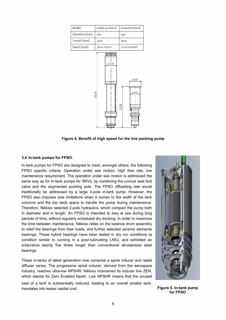
The line packing pump specification presents a more complicated task in that the duty requires the combination of low flow and high head. Traditional centrifugal pump selection based on a 60Hz two-pole motor would have led to a slim 20-stage, 3.4-meter-long pump. With respect to the vertical and longitudinal vertical accelerations environment expressed previously, such a long and thin pump appears as a poor fit. Nikkiso has specifically developed a Small High Pressure pump, which takes advantage of a higher speed of rotation to reconcile low flow and high head. Nikkiso’s line packing pump uses a VFD driven motor at 120Hz. Advantageously, this Small High Pressure pump has only 8 stages and measures only 1.9m in length.
The high speed design was supported by a detailed rotor dynamics analysis and impeller stress calculations.
5
Figure 4. Benefit of high speed for the line packing pump
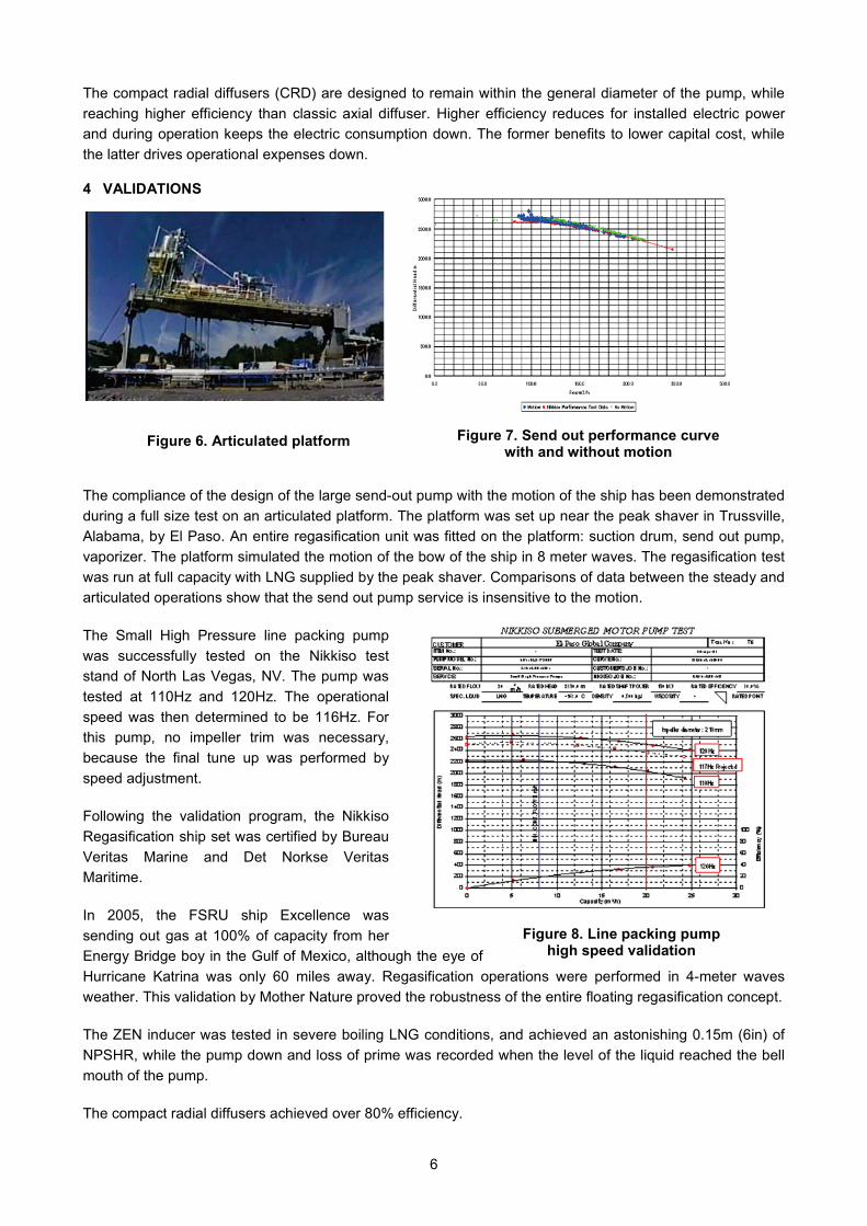
3.4 In-tank pumps for FPSO.
In-tank pumps for FPSO are designed to meet, amongst others, the following FPSO specific criteria: Operation under sea motion, high flow rate, low maintenance requirement. The operation under sea motion is addressed the same way as for In-tank pumps for SRVs, by combining the conical seat foot valve and the segmented pushing pole. The FPSO offloading rate would traditionally be addressed by a large 4-pole in-tank pump. However, the FPSO also imposes size limitations when it comes to the width of the tank columns and the top deck space to handle the pump during maintenance. Therefore, Nikkiso selected 2-pole hydraulics, which compact the pump both in diameter and in length. An FPSO is intended to stay at sea during long periods of time, without regularly scheduled dry docking. In order to maximize the time between maintenance, Nikkiso relies on the balance drum assembly to relief the bearings from their loads, and further selected ceramic elements bearings. These hybrid bearings have been tested in dry run conditions (a condition similar to running in a poor-lubricating LNG), and exhibited an endurance twenty five times longer than conventional all-stainless steel bearings.
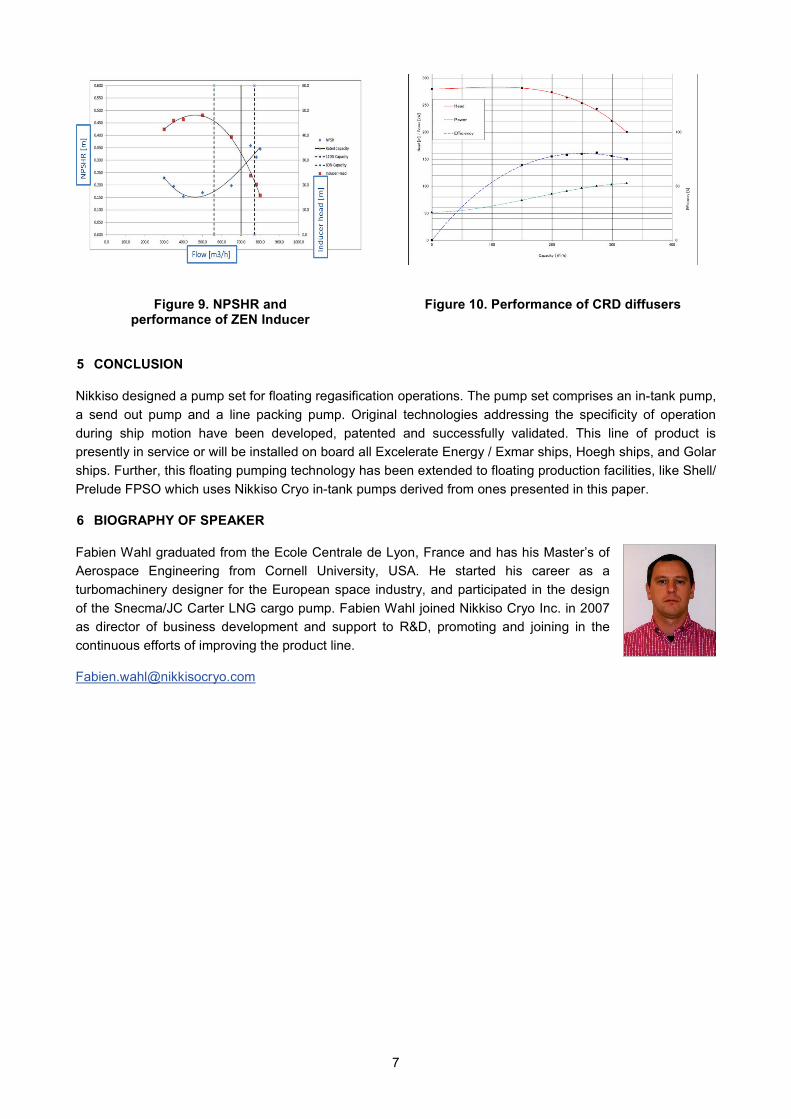
These in-tanks of latest generation now comprise a spiral inducer and radial diffuser vanes. The progressive spiral inducer, derived from the aerospace industry, reaches ultra-low NPSHR. Nikkiso nicknamed its inducer line ZEN, which stands for Zero Enabled Npshr. Low NPSHR means that the unused
heel of a tank is substantially reduced, leading to an overall smaller tank: translates into lesser capital cost. Figure 5. In-tank pump
for FPSO
6
The compact radial diffusers (CRD) are designed to remain within the general diameter of the pump, while reaching higher efficiency than classic axial diffuser. Higher efficiency reduces for installed electric power and during operation keeps the electric consumption down. The former benefits to lower capital cost, while the latter drives operational expenses down.
4 VALIDATIONS
Figure 6. Articulated platform
The compliance of the design of the large send-out pump with the motion of the ship has been demonstrated during a full size test on an articulated platform. The platform was set up near the peak shaver in Trussville, Alabama, by El Paso. An entire regasification unit was fitted on the platform: suction drum, send out pump, vaporizer. The platform simulated the motion of the bow of the ship in 8 meter waves. The regasification test was run at full capacity with LNG supplied by the peak shaver. Comparisons of data between the steady and articulated operations show that the send out pump service is insensitive to the motion.
The Small High Pressure line packing pump was successfully tested on the Nikkiso test stand of North Las Vegas, NV. The pump was tested at 110Hz and 120Hz. The operational speed was then determined to be 116Hz. For this pump, no impeller trim was necessary, because the final tune up was performed by speed adjustment.
Following the validation program, the Nikkiso Regasification ship set was certified by Bureau Veritas Marine and Det Norkse Veritas Maritime.
In 2005, the FSRU ship Excellence was sending out gas at 100% of capacity from her Energy Bridge boy in the Gulf of Mexico, although the eye of Hurricane Katrina was only 60 miles away. Regasification operations were performed in 4-meter waves weather. This validation by Mother Nature proved the robustness of the entire floating regasification concept.
The ZEN inducer was tested in severe boiling LNG conditions, and achieved an astonishing 0.15m (6in) of NPSHR, while the pump down and loss of prime was recorded when the level of the liquid reached the bell mouth of the pump.
The compact radial diffusers achieved over 80% efficiency.
Figure 7. Send out performance curve with and without motion
Figure 8. Line packing pump high speed validation
7
5 CONCLUSION
Nikkiso designed a pump set for floating regasification operations. The pump set comprises an in-tank pump, a send out pump and a line packing pump. Original technologies addressing the specificity of operation during ship motion have been developed, patented and successfully validated. This line of product is presently in service or will be installed on board all Excelerate Energy / Exmar ships, Hoegh ships, and Golar ships. Further, this floating pumping technology has been extended to floating production facilities, like Shell/ Prelude FPSO which uses Nikkiso Cryo in-tank pumps derived from ones presented in this paper.
6 BIOGRAPHY OF SPEAKER
Fabien Wahl graduated from the Ecole Centrale de Lyon, France and has his Master’s of Aerospace Engineering from Cornell University, USA. He started his career as a turbomachinery designer for the European space industry, and participated in the design of the Snecma/JC Carter LNG cargo pump. Fabien Wahl joined Nikkiso Cryo Inc. in 2007 as director of business development and support to R&D, promoting and joining in the continuous efforts of improving the product line.
Figure 9. NPSHR and performance of ZEN Inducer
Figure 10. Performance of CRD diffusers