Embed Size (px)
Citation preview

LNG Vehicle TankEquipment Manual
LNG-545 Revised 2/25/2015
Macro Technologies
RegO® Products Goddard Valve Superior Products Macro Technologies

1
RegO® has prepared this LNG Vehicle Tank Equipment Manual for use by equipment installers and others requiring a reference for field service work to LNG fueling system equipment. This manual deals with subjects that can be useful to field operators and technicians looking to improve system safety and performance. Only qualified personnel should perform installation and maintenance. Be sure all instructions are read and understood before installation, operation, and maintenance. For more in depth technical inquiries, consult the system manufacturer.
This manual is not intended to conflict with federal, state or local ordinances and regulations. These should be observed at all times.
The LNG Vehicle Tank Equipment Manual
This information is intended to be forwarded throughout the product distribution chain. Additional copies are available from RegO® Products Master Distributors.
safETy iNsTrucTioNsFor your safety and improved service life of the product, please read this manual before use and follow the safety instructions carefully. Throughout this manual items appearing in Bold Text highlight conditions that can result in serious injury.
2
Information About LNG .........................................3Safety .................................................................4Physical & Chemical Properties of LNG*.............. 5Approximate Energy Content ...............................5Saturated Vapor Pressures of LNG* .....................6LNG Fuel Tank ......................................................7General Plumbing Components ...........................8 1. Fill receptacle .....................................9 2. Fill check valve ...................................17 3. Primary Relief Valve ...........................18 4. Vent Valve ...........................................21 5. Vapor (Shutoff) Valve .......................... 23 6. Secondary Relief Valve ...................... 26 7. Pressure Builder .................................29 8. Pressure Builder (Shutoff) Valve ........ 32 9. Economizer .........................................35 10. Internal Check Valve ..........................37 11. Fuel Shutoff Valve ..............................37 12. Excess Flow Valve .............................41 13. Final Line Regulator ..........................43Pressure and Leak Testing the Installation ........... 46LNG System Component Replacement ............... 46Repair of Manual Shutoff Valve Bonnet ................ 47Determining Age of RegO® Products ................... 50Conversion Units ..................................................52Maintenance Log
Contents
3
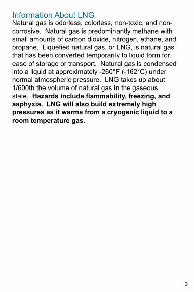
Natural gas is odorless, colorless, non-toxic, and non-corrosive. Natural gas is predominantly methane with small amounts of carbon dioxide, nitrogen, ethane, and propane. Liquefied natural gas, or LNG, is natural gas that has been converted temporarily to liquid form for ease of storage or transport. Natural gas is condensed into a liquid at approximately -260°F (-162°C) under normal atmospheric pressure. LNG takes up about 1/600th the volume of natural gas in the gaseous state. Hazards include flammability, freezing, and asphyxia. LNG will also build extremely high pressures as it warms from a cryogenic liquid to a room temperature gas.
Information About LNG
4
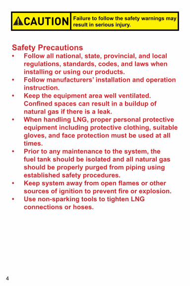
Safety Precautions• Follow all national, state, provincial, and local
regulations, standards, codes, and laws when installing or using our products.
• Follow manufacturers’ installation and operation instruction.
• Keep the equipment area well ventilated. Confined spaces can result in a buildup of natural gas if there is a leak.
• When handling LNG, proper personal protective equipment including protective clothing, suitable gloves, and face protection must be used at all times.
• Prior to any maintenance to the system, the fuel tank should be isolated and all natural gas should be properly purged from piping using established safety procedures.
• Keep system away from open flames or other sources of ignition to prevent fire or explosion.
• Use non-sparking tools to tighten LNG connections or hoses.
CAUTION Failure to follow the safety warnings may result in serious injury.
5
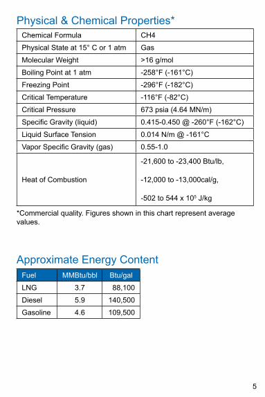
*Commercial quality. Figures shown in this chart represent average values.
Physical & Chemical Properties*Chemical Formula CH4
Physical State at 15° C or 1 atm Gas
Molecular Weight >16 g/mol
Boiling Point at 1 atm -258°F (-161°C)
Freezing Point -296°F (-182°C)
Critical Temperature -116°F (-82°C)
Critical Pressure 673 psia (4.64 MN/m)
Specific Gravity (liquid) 0.415-0.450 @ -260°F (-162°C)
Liquid Surface Tension 0.014 N/m @ -161°C
Vapor Specific Gravity (gas) 0.55-1.0
Heat of Combustion
-21,600 to -23,400 Btu/lb,
-12,000 to -13,000cal/g,
-502 to 544 x 105 J/kg
Approximate Energy ContentFuel MMBtu/bbl Btu/gal
LNG 3.7 88,100
Diesel 5.9 140,500
Gasoline 4.6 109,500
6
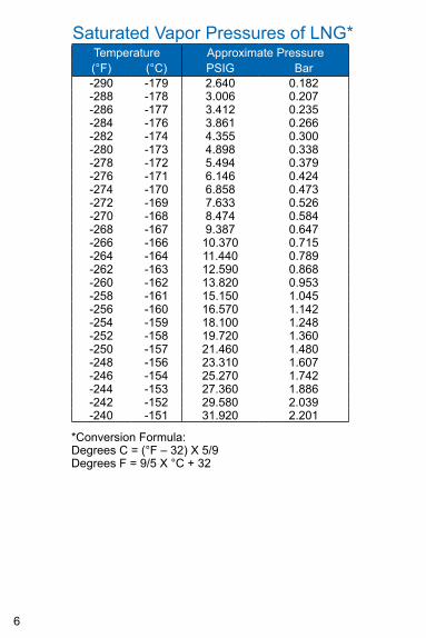
Saturated Vapor Pressures of LNG*Temperature Approximate Pressure(°F) (°C) PSIG Bar-290 -179 2.640 0.182-288 -178 3.006 0.207-286 -177 3.412 0.235-284 -176 3.861 0.266-282 -174 4.355 0.300-280 -173 4.898 0.338-278 -172 5.494 0.379-276 -171 6.146 0.424-274 -170 6.858 0.473-272 -169 7.633 0.526-270 -168 8.474 0.584-268 -167 9.387 0.647-266 -166 10.370 0.715-264 -164 11.440 0.789-262 -163 12.590 0.868-260 -162 13.820 0.953-258 -161 15.150 1.045-256 -160 16.570 1.142-254 -159 18.100 1.248-252 -158 19.720 1.360-250 -157 21.460 1.480-248 -156 23.310 1.607-246 -154 25.270 1.742-244 -153 27.360 1.886-242 -152 29.580 2.039-240 -151 31.920 2.201
*Conversion Formula:Degrees C = (°F – 32) X 5/9Degrees F = 9/5 X °C + 32
7
LNG Vehicle Fuel TankThe LNG fuel tank is a cryogenic container meaning that it stores the natural gas fuel as a highly refrigerated liquid at low pressure. These fuel tanks are typically of stainless steel double-wall, vacuum jacketed construction with extremely efficient insulation between the walls. Vehicular fuel tanks may be at pressures anywhere from less than 5 psig to over 250 psig. LNG must be maintained to remain a liquid, independent of pressure. The insulation, as efficient as it is, will not keep the temperature of LNG cold by itself. LNG will stay at near constant temperature if kept at constant pressure. This phenomenon is called “autorefrigeration”. As long as the LNG vapor boil off is exhausted from the tank, the temperature will remain constant. If the vapor is not drawn off, then the pressure and temperature inside the vessel will rise.
8
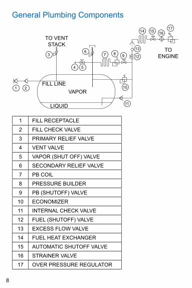
General Plumbing Components
TO VENT STACk
TO ENGINE
FILL LINEVAPOR
LIqUID
12
1 2
3
4 5
67 8 9
13
14 15 1617
10
11
1 FILL RECEPTACLE
2 FILL CHECk VALVE
3 PRIMARY RELIEF VALVE
4 VENT VALVE
5 VAPOR (SHUT OFF) VALVE
6 SECONDARY RELIEF VALVE
7 PB COIL
8 PRESSURE BUILDER
9 PB (SHUTOFF) VALVE
10 ECONOMIZER
11 INTERNAL CHECk VALVE
12 FUEL (SHUTOFF) VALVE
13 EXCESS FLOW VALVE
14 FUEL HEAT EXCHANGER
15 AUTOMATIC SHUTOFF VALVE
16 STRAINER VALVE
17 OVER PRESSURE REGULATOR
9
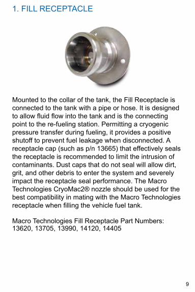
1. FILL RECEPTACLE
Mounted to the collar of the tank, the Fill Receptacle is connected to the tank with a pipe or hose. It is designed to allow fluid flow into the tank and is the connecting point to the re-fueling station. Permitting a cryogenic pressure transfer during fueling, it provides a positive shutoff to prevent fuel leakage when disconnected. A receptacle cap (such as p/n 13665) that effectively seals the receptacle is recommended to limit the intrusion of contaminants. Dust caps that do not seal will allow dirt, grit, and other debris to enter the system and severely impact the receptacle seal performance. The Macro Technologies CryoMac2® nozzle should be used for the best compatibility in mating with the Macro Technologies receptacle when filling the vehicle fuel tank.
Macro Technologies Fill Receptacle Part Numbers: 13620, 13705, 13990, 14120, 14405
10
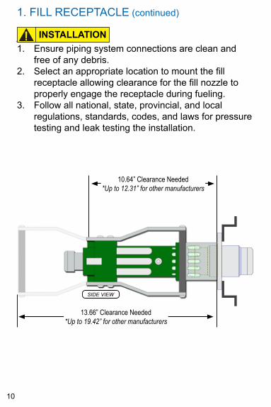
1. FILL RECEPTACLE (continued)
Installation1. Ensure piping system connections are clean and
free of any debris.2. Select an appropriate location to mount the fill
receptacle allowing clearance for the fill nozzle to properly engage the receptacle during fueling.
3. Follow all national, state, provincial, and local regulations, standards, codes, and laws for pressure testing and leak testing the installation.
10.64” Clearance Needed*Up to 12.31” for other manufacturers
SIDE VIEW
13.66” Clearance Needed*Up to 19.42” for other manufacturers
CAUTIONINSTALLATION
11
Maintenance and InspectionPeriodically check for:1. Any signs of corrosion due to water, salt, industrial
pollutants, chemicals, and roadway contaminants.2. Any physical damage that would prevent proper
sealing and usage or that may cause product failure under pressure.
3. Leaks in the internal poppet/seal and end connections of the valve. Check the connections with a suitable leak detecting solution. Do not use detergent soaps that contain ammonia as it can cause stress corrosion cracking. If you are unsure, after conducting the leak test rinse the affected area with clean water.
1. FILL RECEPTACLE (continued)
Maintenance and Inspection
12
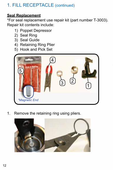
1. Remove the retaining ring using pliers.
1) Poppet Depressor2) Seal Ring3) Seal Guide4) Retaining Ring Plier5) Hook and Pick Set
5
23
4
*Magnetic End
1
*
Seal Replacement*For seal replacement use repair kit (part number T-3003). Repair kit contents include:
1. FILL RECEPTACLE (continued)
13
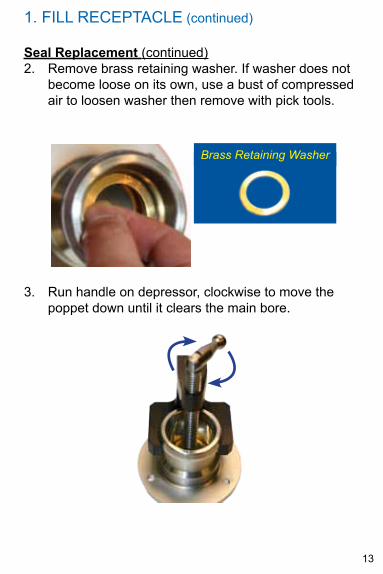
Seal Replacement (continued)2. Remove brass retaining washer. If washer does not
become loose on its own, use a bust of compressed air to loosen washer then remove with pick tools.
Brass Retaining Washer
3. Run handle on depressor, clockwise to move the poppet down until it clears the main bore.
1. FILL RECEPTACLE (continued)
14
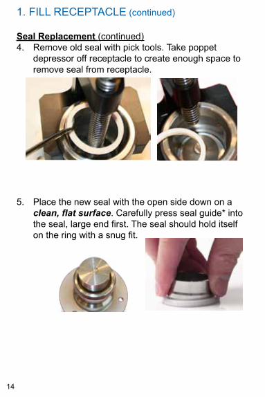
Seal Replacement (continued)4. Remove old seal with pick tools. Take poppet
depressor off receptacle to create enough space to remove seal from receptacle.
5. Place the new seal with the open side down on a clean, flat surface. Carefully press seal guide* into the seal, large end first. The seal should hold itself on the ring with a snug fit.
1. FILL RECEPTACLE (continued)
15
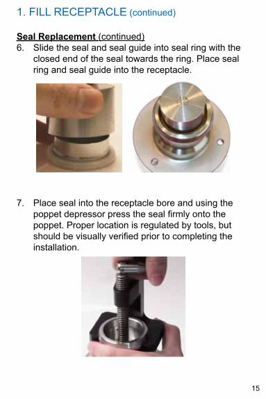
Seal Replacement (continued)6. Slide the seal and seal guide into seal ring with the
closed end of the seal towards the ring. Place seal ring and seal guide into the receptacle.
7. Place seal into the receptacle bore and using the poppet depressor press the seal firmly onto the poppet. Proper location is regulated by tools, but should be visually verified prior to completing the installation.
1. FILL RECEPTACLE (continued)
16
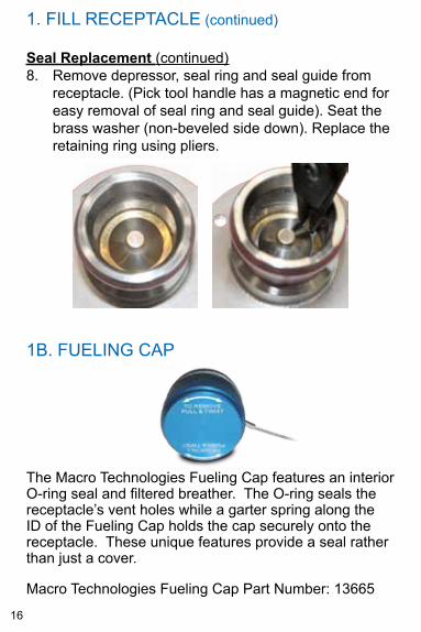
Seal Replacement (continued)8. Remove depressor, seal ring and seal guide from
receptacle. (Pick tool handle has a magnetic end for easy removal of seal ring and seal guide). Seat the brass washer (non-beveled side down). Replace the retaining ring using pliers.
1. FILL RECEPTACLE (continued)
1B. FUELING CAP
The Macro Technologies Fueling Cap features an interior O-ring seal and filtered breather. The O-ring seals the receptacle’s vent holes while a garter spring along the ID of the Fueling Cap holds the cap securely onto the receptacle. These unique features provide a seal rather than just a cover.
Macro Technologies Fueling Cap Part Number: 13665
17
2. FILL CHECk VALVE
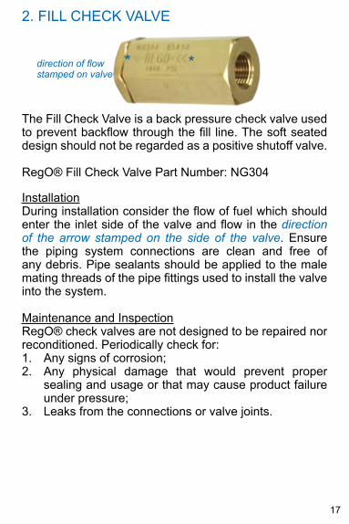
The Fill Check Valve is a back pressure check valve used to prevent backflow through the fill line. The soft seated design should not be regarded as a positive shutoff valve.
RegO® Fill Check Valve Part Number: NG304
InstallationDuring installation consider the flow of fuel which should enter the inlet side of the valve and flow in the direction of the arrow stamped on the side of the valve. Ensure the piping system connections are clean and free of any debris. Pipe sealants should be applied to the male mating threads of the pipe fittings used to install the valve into the system.
Maintenance and InspectionRegO® check valves are not designed to be repaired nor reconditioned. Periodically check for:1. Any signs of corrosion;2. Any physical damage that would prevent proper
sealing and usage or that may cause product failure under pressure;
3. Leaks from the connections or valve joints.
direction of flow *stamped on valve
*
18
3. PRIMARY RELIEF VALVE
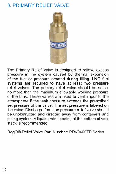
The Primary Relief Valve is designed to relieve excess pressure in the system caused by thermal expansion of the fuel or pressure created during filling. LNG fuel systems are required to have at least two pressure relief valves. The primary relief valve should be set at no more than the maximum allowable working pressure of the tank. These valves are used to vent vapor to the atmosphere if the tank pressure exceeds the prescribed set pressure of the valve. The set pressure is labeled on the valve. Discharge from the pressure relief valve should be unobstructed and directed away from containers and piping system. A liquid drain opening at the bottom of vent stack is recommended.
RegO® Relief Valve Part Number: PRV9400TP Series
19
3. PRIMARY RELIEF VALVE (continued)
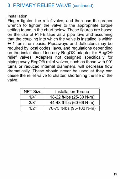
InstallationFinger tighten the relief valve, and then use the proper wrench to tighten the valve to the appropriate torque setting found in the chart below. These figures are based on the use of PTFE tape as a pipe luve and assuming that the coupling into which the valve is installed is within +/-1 turn from basic. Pipeaways and deflectors may be required by local codes, laws, and regulations depending on the installation. Use only RegO® adapter for RegO® relief valves. Adapters not designed specifically for piping away RegO® relief valves, such as those with 90° turns or reduced internal diameters, will decrease flow dramatically. These should never be used at they can cause the relief valve to chatter, shortening the life of the valve.
NPT Size Installation Torque1/4” 18-22 ft-lbs (25-30 N-m)3/8” 44-48 ft-lbs (60-66 N-m)1/2” 70-75 ft-lbs (95-102 N-m)
20
3. PRIMARY RELIEF VALVE (continued)
Maintenance and Inspection
RegO® pressure relief valves are not designed to be repaired nor reconditioned. If a valve needs to be replaced, do not replace with a higher pressure relief valve.
Periodically check for:1. Any signs of corrosion due to water, salt, industrial
pollutants, chemicals, and roadway contaminants.2. Any physical damage that would prevent proper
sealing and usage or that may cause product failure under pressure.
3. Leaks in the flange connection and stoppage in the relief orifice. Check all connections with a suitable leak detecting solution. Do not use detergent soaps that contain ammonia as it can cause stress corrosion cracking. If you are unsure, after conducting the leak test rinse the affected area with clean water.
Care must be taken when inspecting the pressure relief valve. Do not look directly into the relief orifice while it is connected to the system, or severe personal injury can occur.
21
4. VENT VALVE
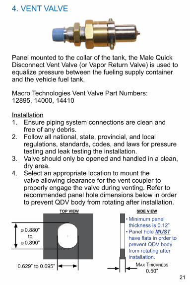
Panel mounted to the collar of the tank, the Male quick Disconnect Vent Valve (or Vapor Return Valve) is used to equalize pressure between the fueling supply container and the vehicle fuel tank.
Macro Technologies Vent Valve Part Numbers: 12895, 14000, 14410
Installation1. Ensure piping system connections are clean and
free of any debris.2. Follow all national, state, provincial, and local
regulations, standards, codes, and laws for pressure testing and leak testing the installation.
3. Valve should only be opened and handled in a clean, dry area.
4. Select an appropriate location to mount the valve allowing clearance for the vent coupler to properly engage the valve during venting. Refer to recommended panel hole dimensions below in order to prevent qDV body from rotating after installation.
+
• Minimum panel thickness is 0.12”
• Panel hole MUST have flats in order to prevent qDV body from rotating after installation.
Max Thickness 0.50”
+
0.629” to 0.695”
ø 0.880” to
ø 0.890”
TOP vIeW SIde vIeW
22
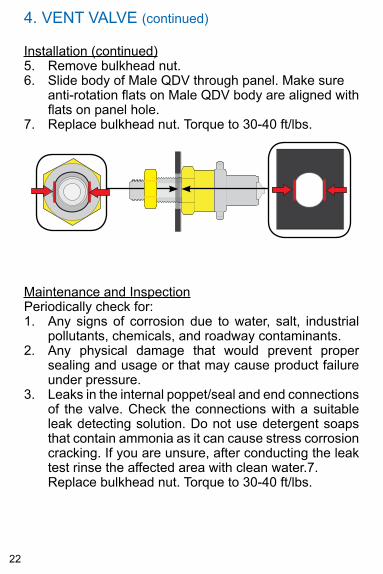
4. VENT VALVE (continued)
Installation (continued)5. Remove bulkhead nut.6. Slide body of Male qDV through panel. Make sure
anti-rotation flats on Male qDV body are aligned with flats on panel hole.
7. Replace bulkhead nut. Torque to 30-40 ft/lbs.
Maintenance and InspectionPeriodically check for:1. Any signs of corrosion due to water, salt, industrial
pollutants, chemicals, and roadway contaminants.2. Any physical damage that would prevent proper
sealing and usage or that may cause product failure under pressure.
3. Leaks in the internal poppet/seal and end connections of the valve. Check the connections with a suitable leak detecting solution. Do not use detergent soaps that contain ammonia as it can cause stress corrosion cracking. If you are unsure, after conducting the leak test rinse the affected area with clean water.7. Replace bulkhead nut. Torque to 30-40 ft/lbs.
23
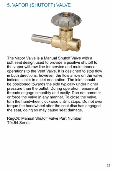
5. VAPOR (SHUTOFF) VALVE
The Vapor Valve is a Manual Shutoff Valve with a soft seat design used to provide a positive shutoff to the vapor withraw line for service and maintenance operations to the Vent Valve. It is designed to stop flow in both directions, however, the flow arrow on the valve indicates inlet to outlet orientation. The inlet should be positioned towards the side typically under higher pressure than the outlet. During operation, ensure al threads engage smoothly and easily. Don not hammer or force the valve in any manner. To close the valve, turn the handwheel clockwise until it stops. Do not over torque the handwheel after the seat disc has engaged the seat, doing so may cause seat damage.
RegO® Manual Shutoff Valve Part Number: T9464 Series
24
5. VAPOR (SHUTOFF) VALVE (continued)
Installation
Before the valve can be welded into place, turn the handwheel counterclockwise to backseat the seat disc, avoiding damage to the seat during heating.
1. Wrap a thoroughly wet towel around the valve body to prevent heat damage to valve components while welding.
2. Ensure connections are clean and free of any debris. 3. Position the valve such that the flow arrow is in the
proper direction.4. Weld the pipe connection of the valve body to the
piping system. Follow all national, regional and/or local codes, standards, and specifications for proper welding procedures.
5. If the valve has a threaded inlet or outlet connection, apply a sealant that is appropriate to the male threads of the connection.
6. Restrain the valve with a vise or suitable wrench, and using an appropriate wench for connection, tighten the connection to the body using standard NPT engagement 2-3 wrench turns beyond hand tight. The torques shown below is for reference only.
7. Check all connections with a suitable leak detecting solution. Do not use detergent soaps that contain ammonia as it can cause stress corrosion cracking. If you are unsure, after conducting the leak test rinse the affected area with clean water.
25
5. VAPOR (SHUTOFF) VALVE (continued)
Maintenance and InspectionPeriodically check for:1. Any signs of corrosion;2. Any physical damage that would prevent proper
sealing and usage or that may cause product failure under pressure;
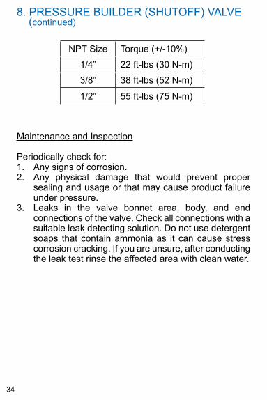
3. Leaks in the valve bonnet area, body, and end connections of the valve. Check all connections with a suitable leak detecting solution. Do not use detergent soaps that contain ammonia as it can cause stress corrosion cracking. If you are unsure, after conducting the leak test rinse the affected area with clean water.
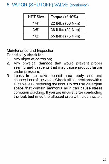
NPT Size Torque (+/-10%)
1/4” 22 ft-lbs (30 N-m)
3/8” 38 ft-lbs (52 N-m)
1/2” 55 ft-lbs (75 N-m)
26
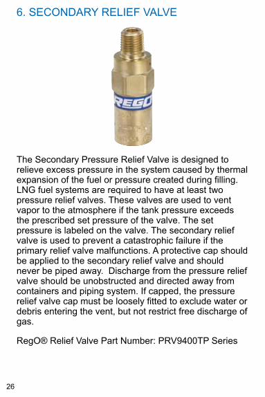
6. SECONDARY RELIEF VALVE
The Secondary Pressure Relief Valve is designed to relieve excess pressure in the system caused by thermal expansion of the fuel or pressure created during filling. LNG fuel systems are required to have at least two pressure relief valves. These valves are used to vent vapor to the atmosphere if the tank pressure exceeds the prescribed set pressure of the valve. The set pressure is labeled on the valve. The secondary relief valve is used to prevent a catastrophic failure if the primary relief valve malfunctions. A protective cap should be applied to the secondary relief valve and should never be piped away. Discharge from the pressure relief valve should be unobstructed and directed away from containers and piping system. If capped, the pressure relief valve cap must be loosely fitted to exclude water or debris entering the vent, but not restrict free discharge of gas.
RegO® Relief Valve Part Number: PRV9400TP Series
27
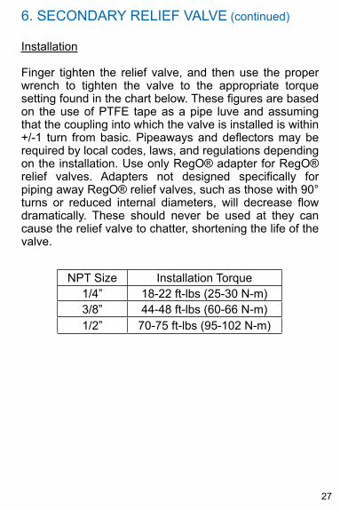
6. SECONDARY RELIEF VALVE (continued)
Installation
Finger tighten the relief valve, and then use the proper wrench to tighten the valve to the appropriate torque setting found in the chart below. These figures are based on the use of PTFE tape as a pipe luve and assuming that the coupling into which the valve is installed is within +/-1 turn from basic. Pipeaways and deflectors may be required by local codes, laws, and regulations depending on the installation. Use only RegO® adapter for RegO® relief valves. Adapters not designed specifically for piping away RegO® relief valves, such as those with 90° turns or reduced internal diameters, will decrease flow dramatically. These should never be used at they can cause the relief valve to chatter, shortening the life of the valve.
NPT Size Installation Torque1/4” 18-22 ft-lbs (25-30 N-m)3/8” 44-48 ft-lbs (60-66 N-m)1/2” 70-75 ft-lbs (95-102 N-m)
28
Maintenance and Inspection
RegO® pressure relief valves are not designed to be repaired nor reconditioned. If a valve needs to be replaced, do not replace with a higher pressure relief valve.
Periodically check for:1. Any signs of corrosion due to water, salt, industrial
pollutants, chemicals, and roadway contaminants.2. Any physical damage that would prevent proper
sealing and usage or that may cause product failure under pressure.
3. Leaks in the flange connection and stoppage in the relief orifice. Check all connections with a suitable leak detecting solution. Do not use detergent soaps that contain ammonia as it can cause stress corrosion cracking. If you are unsure, after conducting the leak test rinse the affected area with clean water.
Care must be taken when inspecting the pressure relief valve. Do not look directly into the relief orifice while it is connected to the system, or severe personal injury can occur.
6. SECONDARY RELIEF VALVE (continued)
29
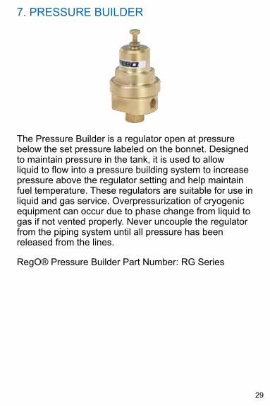
7. PRESSURE BUILDER
The Pressure Builder is a regulator open at pressure below the set pressure labeled on the bonnet. Designed to maintain pressure in the tank, it is used to allow liquid to flow into a pressure building system to increase pressure above the regulator setting and help maintain fuel temperature. These regulators are suitable for use in liquid and gas service. Overpressurization of cryogenic equipment can occur due to phase change from liquid to gas if not vented properly. Never uncouple the regulator from the piping system until all pressure has been released from the lines.
RegO® Pressure Builder Part Number: RG Series
30
7. PRESSURE BUILDER (continued)
Installation
1. Clean dirt and foreign material from all piping and fittings, inside and out.
2. Apply a pipe joint compound suitable for the gas service (such as PTFE tape) to the male threads on the piping. Take care not to apply any compound or tape to the first thread in order to avoid minute particles from breaking off and lodging on the seat.
3. Be sure the inlet and outlet of the regulator are correctly installed in-line according to the designed flow pattern and markings of the regulator body.
4. Position the regulator to protect vents from the elements of ice, snowdrifts, rain, dirt, bugs, paint, or other foreign material.
5. Follow all national, state, provincial, and local regulations, standards, codes, and laws for pressure testing and leak testing the installation.
31
7. PRESSURE BUILDER (continued)
Maintenance and Inspection
To set the regulator outlet pressure:1. Loosen the locknut by turning counterclockwise.2. Increase pressure by turning the adjusting screw
clockwise, decrease by turning the adjusting screw counterclockwise.
3. After achieving the desired pressure, cycle the regulator several times by operating a downstream flow control device. Readjust if necessary.
4. While holding the adjusting screw from turning, tighten the locknut by turning clockwise.
Periodically check for:1. Any signs of corrosion due to water, salt, industrial
pollutants, chemicals, and roadway contaminants;2. Any physical damage that would prevent proper
sealing and usage or that may cause product failure under pressure;
3. Leaks in the end connections of the regulator. Check all connections with a suitable leak detecting solution. Do not use detergent soaps that contain ammonia as it can cause stress corrosion cracking. If you are unsure, after conducting the leak test rinse the affected area with clean water.
4. Proper operation as foreign matter may affect the performance of the regulator.
32
8. PRESSURE BUILDER (SHUTOFF) VALVE
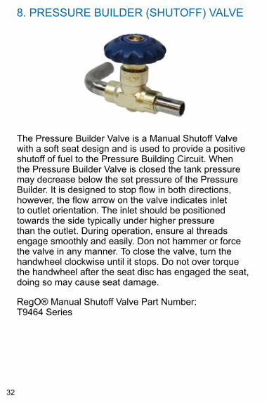
The Pressure Builder Valve is a Manual Shutoff Valve with a soft seat design and is used to provide a positive shutoff of fuel to the Pressure Building Circuit. When the Pressure Builder Valve is closed the tank pressure may decrease below the set pressure of the Pressure Builder. It is designed to stop flow in both directions, however, the flow arrow on the valve indicates inlet to outlet orientation. The inlet should be positioned towards the side typically under higher pressure than the outlet. During operation, ensure al threads engage smoothly and easily. Don not hammer or force the valve in any manner. To close the valve, turn the handwheel clockwise until it stops. Do not over torque the handwheel after the seat disc has engaged the seat, doing so may cause seat damage.
RegO® Manual Shutoff Valve Part Number: T9464 Series
33
8. PRESSURE BUILDER (SHUTOFF) VALVE
Installation
Before the valve can be welded into place, turn the handwheel counterclockwise to backseat the seat disc, avoiding damage to the seat during heating.1. Wrap a thoroughly wet towel around the valve body
to prevent heat damage to valve components while welding.
2. Ensure connections are clean and free of any debris. 3. Position the valve such that the flow arrow is in the
proper direction.4. Weld the pipe connection of the valve body to the
piping system. Follow all national, regional and/or local codes, standards, and specifications for proper welding procedures.
5. If the valve has a threaded inlet or outlet connection, apply a sealant that is appropriate to the male threads of the connection.
6. Restrain the valve with a vise or suitable wrench, and using an appropriate wench for connection, tighten the connection to the body using standard NPT engagement 2-3 wrench turns beyond hand tight. The torques shown below is for reference only.
7. Check all connections with a suitable leak detecting solution. Do not use detergent soaps that contain ammonia as it can cause stress corrosion cracking. If you are unsure, after conducting the leak test rinse the affected area with clean water.
(continued)
34
8. PRESSURE BUILDER (SHUTOFF) VALVE
Maintenance and Inspection
Periodically check for:1. Any signs of corrosion.2. Any physical damage that would prevent proper
sealing and usage or that may cause product failure under pressure.
3. Leaks in the valve bonnet area, body, and end connections of the valve. Check all connections with a suitable leak detecting solution. Do not use detergent soaps that contain ammonia as it can cause stress corrosion cracking. If you are unsure, after conducting the leak test rinse the affected area with clean water.
(continued)
NPT Size Torque (+/-10%)
1/4” 22 ft-lbs (30 N-m)
3/8” 38 ft-lbs (52 N-m)
1/2” 55 ft-lbs (75 N-m)
35
9. ECONOMIZER
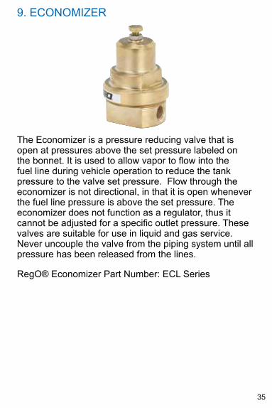
The Economizer is a pressure reducing valve that is open at pressures above the set pressure labeled on the bonnet. It is used to allow vapor to flow into the fuel line during vehicle operation to reduce the tank pressure to the valve set pressure. Flow through the economizer is not directional, in that it is open whenever the fuel line pressure is above the set pressure. The economizer does not function as a regulator, thus it cannot be adjusted for a specific outlet pressure. These valves are suitable for use in liquid and gas service. Never uncouple the valve from the piping system until all pressure has been released from the lines.
RegO® Economizer Part Number: ECL Series
36
9. ECONOMIZER (continued)
Installation
1. Clean dirt and foreign material from all piping and fittings, inside and out.
2. Apply a pipe joint compound suitable for gas service (such as PTFE tape) to the male threads on the piping. Take care not to apply any compound or tape to the first thread, in order to avoid minute particles from breaking off and lodging on the seat.
3. Position the Economizer to protect vents from the elements.
4. Follow all national, state, provincial, and local regulations, standards, codes, and laws for pressure testing and leak testing the installation.
Maintenance and Inspection
Periodically check for:1. Any signs of corrosion due to water, salt, industrial
pollutants, chemicals, and roadway contaminants;2. Any physical damage that would prevent proper
sealing and usage or that may cause product failure under pressure;
3. Leaks in the end connections of the economizer. Check all connections with a suitable leak detecting solution. Do not use detergent soaps that contain ammonia as it can cause stress corrosion cracking. If you are unsure, after conducting the leak test rinse the affected area with clean water.
4. Proper operation as foreign matter may affect the performance of the economizer.
37
10. INTERNAL CHECk VALVE
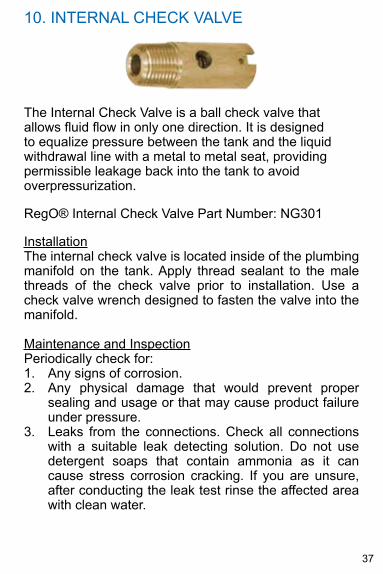
The Internal Check Valve is a ball check valve that allows fluid flow in only one direction. It is designed to equalize pressure between the tank and the liquid withdrawal line with a metal to metal seat, providing permissible leakage back into the tank to avoid overpressurization.
RegO® Internal Check Valve Part Number: NG301
InstallationThe internal check valve is located inside of the plumbing manifold on the tank. Apply thread sealant to the male threads of the check valve prior to installation. Use a check valve wrench designed to fasten the valve into the manifold.
Maintenance and InspectionPeriodically check for:1. Any signs of corrosion.2. Any physical damage that would prevent proper
sealing and usage or that may cause product failure under pressure.
3. Leaks from the connections. Check all connections with a suitable leak detecting solution. Do not use detergent soaps that contain ammonia as it can cause stress corrosion cracking. If you are unsure, after conducting the leak test rinse the affected area with clean water.
38
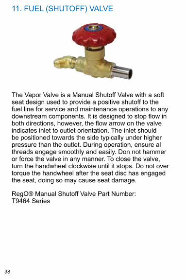
11. FUEL (SHUTOFF) VALVE
The Vapor Valve is a Manual Shutoff Valve with a soft seat design used to provide a positive shutoff to the fuel line for service and maintenance operations to any downstream components. It is designed to stop flow in both directions, however, the flow arrow on the valve indicates inlet to outlet orientation. The inlet should be positioned towards the side typically under higher pressure than the outlet. During operation, ensure al threads engage smoothly and easily. Don not hammer or force the valve in any manner. To close the valve, turn the handwheel clockwise until it stops. Do not over torque the handwheel after the seat disc has engaged the seat, doing so may cause seat damage.
RegO® Manual Shutoff Valve Part Number: T9464 Series
39
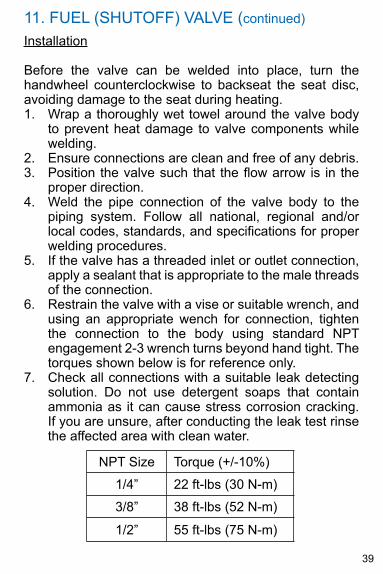
11. FUEL (SHUTOFF) VALVE (continued)
Installation
Before the valve can be welded into place, turn the handwheel counterclockwise to backseat the seat disc, avoiding damage to the seat during heating.1. Wrap a thoroughly wet towel around the valve body
to prevent heat damage to valve components while welding.
2. Ensure connections are clean and free of any debris. 3. Position the valve such that the flow arrow is in the
proper direction. 4. Weld the pipe connection of the valve body to the
piping system. Follow all national, regional and/or local codes, standards, and specifications for proper welding procedures.
5. If the valve has a threaded inlet or outlet connection, apply a sealant that is appropriate to the male threads of the connection.
6. Restrain the valve with a vise or suitable wrench, and using an appropriate wench for connection, tighten the connection to the body using standard NPT engagement 2-3 wrench turns beyond hand tight. The torques shown below is for reference only.
7. Check all connections with a suitable leak detecting solution. Do not use detergent soaps that contain ammonia as it can cause stress corrosion cracking. If you are unsure, after conducting the leak test rinse the affected area with clean water.
NPT Size Torque (+/-10%)
1/4” 22 ft-lbs (30 N-m)
3/8” 38 ft-lbs (52 N-m)
1/2” 55 ft-lbs (75 N-m)
40
11. FUEL (SHUTOFF) VALVE (continued)
Maintenance and Inspection
Periodically check for:1. Any signs of corrosion.2. Any physical damage that would prevent proper
sealing and usage or that may cause product failure under pressure.
3. Leaks in the valve bonnet area, body, and end connections of the valve. Check all connections with a suitable leak detecting solution. Do not use detergent soaps that contain ammonia as it can cause stress corrosion cracking. If you are unsure, after conducting the leak test rinse the affected area with clean water.
41
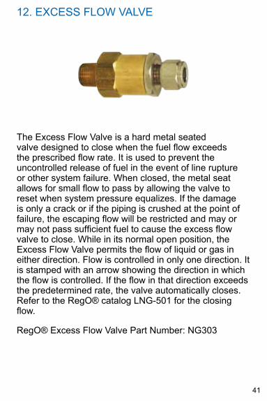
12. EXCESS FLOW VALVE
The Excess Flow Valve is a hard metal seated valve designed to close when the fuel flow exceeds the prescribed flow rate. It is used to prevent the uncontrolled release of fuel in the event of line rupture or other system failure. When closed, the metal seat allows for small flow to pass by allowing the valve to reset when system pressure equalizes. If the damage is only a crack or if the piping is crushed at the point of failure, the escaping flow will be restricted and may or may not pass sufficient fuel to cause the excess flow valve to close. While in its normal open position, the Excess Flow Valve permits the flow of liquid or gas in either direction. Flow is controlled in only one direction. It is stamped with an arrow showing the direction in which the flow is controlled. If the flow in that direction exceeds the predetermined rate, the valve automatically closes. Refer to the RegO® catalog LNG-501 for the closing flow.
RegO® Excess Flow Valve Part Number: NG303
42
12. EXCESS FLOW VALVE (continued)
InstallationThe standard excess flow outlet consists of a 2 piece ferrule type tube fitting. The tubing wall thickness should be per fitting manufacturers’ specification (Parker A-lok, Swagelok, or equivalent) for gas service. Since excess flow valves depend on flow for closure, the line leading away from the excess flow valve should be large enough so that it will not excessively restrict the flow. If the pipe run is restricted by numerous elbows and tees, or other fittings, consideration should be given to the use of larger size pipe and fittings. Never use a pipe size smaller than that of the excess flow valve.
Maintenance and InspectionRegO excess flow valves are not designed to be repaired nor reconditioned. Periodically check for:1. Any signs of corrosion;2. Any physical damage that would prevent proper
sealing and usage or that may cause product failure under pressure;
3. Leaks from the connections or valve joints. Check all connections with a suitable leak detecting solution. Do not use detergent soaps that contain ammonia as it can cause stress corrosion cracking. If you are unsure, after conducting the leak test rinse the affected area with clean water.
Excess flow valves should be tested and proven at the time of installation and at periodic intervals not to exceed one year. The test should include a simulated break in the line by the quick opening of a shutoff valve. If the valve closes under these conditions, it is reasonable to assume that it will close in the event of excess flow conditions.
43
13. FINAL LINE REGULATOR (continued)
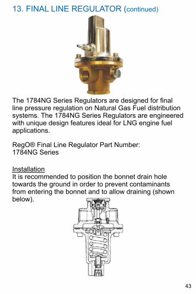
The 1784NG Series Regulators are designed for final line pressure regulation on Natural Gas Fuel distribution systems. The 1784NG Series Regulators are engineered with unique design features ideal for LNG engine fuel applications.
RegO® Final Line Regulator Part Number: 1784NG Series
InstallationIt is recommended to position the bonnet drain hole towards the ground in order to prevent contaminants from entering the bonnet and to allow draining (shown below).
44
13. FINAL LINE REGULATOR
Installation (continued)
The use of a line-strainer upstream of the regulator is recommended to prevent contamination and even damage to the valve seat. 1. Apply a pipe joint compound suitable for natural gas
service (such as PTFE tape) to the male threads on the piping.
2. Clean dirt and foreign matter from all piping and fittings.
3. Follow all national, state, provincial, and local regulations, standards, codes, and laws for pressure testing and leak testing the installation.
Note: The purpose of this valve is to reduce the line pressure. IT IS NOT A SAFeTY devICe
Maintenance and Inspection
To set the regulator outlet pressure:1. Loosen the locknut by turning counterclockwise.2. Increase pressure by turning the adjusting screw
clockwise, decrease by turning the adjusting screw counterclockwise.
3. After achieving the desired pressure, cycle the regulator several times by operating a downstream flow control device. Readjust if necessary.
4. While holding the adjusting screw from turning, tighten the locknut by turning clockwise.
45
13. FINAL LINE REGULATOR
Maintenance and Inspection (continued)
Periodically check for:1. Any signs of corrosion due to water, salt, industrial
pollutants, chemicals, and roadway contaminants.2. Any physical damage that would prevent proper
sealing and usage or that may cause product failure under pressure.
3. Leaks in the end connections of the regulator. Check the connections with a suitable leak detecting solution. Do not use detergent soaps that contain ammonia as it can cause stress corrosion cracking. If you are unsure, after conducting the leak test rinse the affected area with clean water.
Proper operation as foreign matter may affect the performance of the regulator.
46
PRESSURE AND LEAk TESTING THE INSTALLATIONFollow all local or national codes and standards for pressure testing and leak checking the installation of all components before startup of the system. After assembly, all piping system components shall be tested and proved free of leaks at a pressure, not less than the maximum operating pressure of the system. Allow sufficient time for thread sealants to cure before testing. Small leaks can be detected through bubble testing. A commercially available, non-corrosive bubble test solution should be used, not soap. Most soap contains chlorine and surfactants that can breakdown sealants and cause stress-cracking. The system shall be leak-tested in accordance with the governing construction code or standard. All leaks shall be repaired.
LNG SYSTEM COMPONENT REPLACEMENTOriginal RegO/Macro parts must be used for any repair or replacement. Never remove the system components without relieving all pressure in the system line under maintenance by properly purging the piping using established safety procedures. In the event that the component cannot be isolated by closing shutoff valves, purge the tank of fuel and release all pressure from the system using established safety procedures prior to performing any work. For components that can be isolated from the tank by closing shutoff valves, be sure to check the pressure of the system line under maintenance prior to performing any work.
47
RegO® T9464-80 Repair kit for T9464 Series ValvesA. Disassembly:
Note: Discard all components that are removed from the valve.1. Open the valve by turning the handwheel
counterclockwise to the full open position and evacuate trapped gas from the system.
NOTE: If the bonnet wrench flats can be accessed by a wrench without remobing the handwheel skip Step 2 and proceed to Step 3.2. To expose the bonnet wrench flats, remove the
handwheel nut (or handwheel screw if the valve is an older version) from the valve stem and then remove the handwheel and any components in the handwheel from the valve stem.
3. Using a large adjustable wrench to hold the valve and support the valve body, remove the bonnet assembly by turning the bonnet counterclockwise with a 13/16” wrench. The wrench must be capable of developing at least 1100 in-lbs (92 ft-lbs) torque.
4. Remove the copper gasket from the valve body.5. Inspect the valve body and clean if necessary.
Ensure interior and seal areas are free of dirt, residue, and foreign particles.
1. Cycle the valve stem opened and closed several times to ensure smooth operation.
2. Slowly pressurize the system. Check valve for proper operation and all seal points for leaks by inspecting thoroughly, using a high quality leak detection solution.
REPAIR OF THE SHUTOFF VALVE BONNET
48
A. Reassembly:1. Remove the copper gasket from the wire tie on
the new bonnet assembly. 2. Position the new copper gasket in the valve
body on the shoulder in the valve body below the threads.
3. Holding the new bonnet in one hand, turn the handwheel counterclockwise to ensure that the seat poppet seat poppet is in the fully open (backseated) position.
4. Thread new bonnet into the valve body until hand tight.
5. While supporting the valve body with the appropriately sized adjustable wrench, tighten the Bonnet into the valve body using a 13/16” wrench to 900-1100 in-lbs (75-92 ft-lbs).
NOTe: dO NOT ReMOve THe HANdWHeeLA 13/16” crowfoot wrench can be used in conjunction with a torque wrench and socket extension to tighten the bonnet assembly to the proper torque
6. Cycle the valve stem opened and closed several times to ensure smooth operation.
7. Slowly pressurize the system. Check valve for proper operation and all seal points for leaks by inspecting thoroughly, using a high quality leak detection solution.
REPAIR OF THE SHUTOFF VALVE BONNET(continued)
49
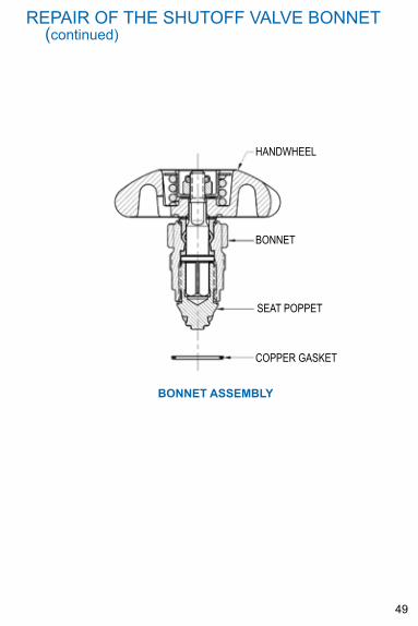
REPAIR OF THE SHUTOFF VALVE BONNET(continued)
haNdwheel
bONNeT
SeaT POPPeT
COPPeR GaSkeT
BONNeT ASSeMBLY
50
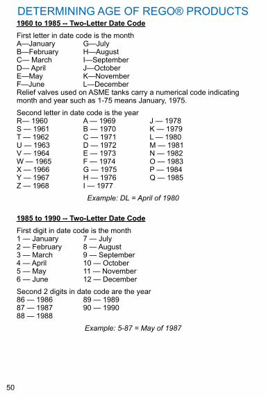
1960 to 1985 -- Two-Letter date CodeFirst letter in date code is the monthA—January G—JulyB—February H—AugustC— March I—SeptemberD— April J—OctoberE—May k—NovemberF—June L—DecemberRelief valves used on ASME tanks carry a numerical code indicating month and year such as 1-75 means January, 1975.Second letter in date code is the yearR— 1960 A — 1969 J — 1978S — 1961 B — 1970 k — 1979T — 1962 C — 1971 L — 1980U — 1963 D — 1972 M — 1981V — 1964 E — 1973 N — 1982W — 1965 F — 1974 O — 1983X — 1966 G — 1975 P — 1984Y — 1967 H — 1976 q — 1985Z — 1968 I — 1977
Example: DL = April of 1980
DETERMINING AGE OF REGO® PRODUCTS
1985 to 1990 -- Two-Letter date CodeFirst digit in date code is the month1 — January 7 — July2 — February 8 — August3 — March 9 — September4 — April 10 — October5 — May 11 — November6 — June 12 — DecemberSecond 2 digits in date code are the year86 — 1986 89 — 198987 — 1987 90 — 199088 — 1988
Example: 5-87 = May of 1987
51
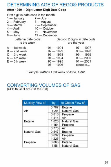
After 1990 -- digit-Letter-digit date CodeFirst digit in date code is the month1 — January 7 — July2 — February 8 — August3 — March 9 — September4 — April 10 — October5 — May 11 — November6 — June 12 — December
DETERMINING AGE OF REGO® PRODUCTS
Letter in date code is the week
A — 1st weekB — 2nd weekC — 3rd weekD — 4th weekE — 5th week
Second 2 digits in date codeare the year
91 — 199192 — 199293 — 199394 — 1994 95 — 1995 96 — 1996
97 — 199798 — 199899 — 199900 — 200001 — 2001etcetera...
Example: 6A92 = First week of June, 1992
CONVERTING VOLUMES OF GAS(CFH to CFH or CFM to CFM)
Multiply Flow of: by to Obtain Flow of:
Air0.707 Butane1.29 Natural Gas0.816 Propane
Butane1.414 Air1.826 Natural Gas1.154 Propane
Natural Gas0.775 Air0.547 Butane0.632 Propane
Propane1.225 Air0.866 Butane1.58 Natural Gas
52
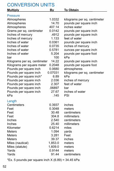
CONVERSION UNITSMultiply By To Obtain
PressureAtmospheres 1.0332 kilograms per sq. centimeterAtmospheres 14.70 pounds per square inchAtmospheres 407.14 inches waterGrams per sq. centimeter 0.0142 pounds per square inchInches of mercury .4912 pounds per square inchInches of mercury 1.133 feet of waterInches of water 0.0361 pounds per square inchInches of water 0.0735 inches of mercuryInches of water 0.5781 ounces per square inchInches of water 5.204 pounds per square footbar 100 kPakilograms per sq. centimeter 14.22 pounds per square inchkilograms per square meter 0.2048 pounds per square footPounds per square inch 0.0680 atmospheresPounds per square inch 0.07031 kilograms per sq. centimeterPounds per square inch* 6.89 kPaPounds per square inch 2.036 inches of mercuryPounds per square inch 2.307 feet of waterPounds per square inch .06897 barPounds per square inch 27.67 inches of waterkPa .145 PSI
LengthCentimeters 0.3937 inchesFeet 0.3048 metersFeet 30.48 centimetersFeet 304.8 millimetersInches 2.540 centimetersInches 25.40 millimeterskilometer 0.6214 milesMeters 1.094 yardsMeters 3.281 FeetMeters 39.37 inchesMiles (nautical) 1,853.0 metersMiles (statute) 1,609.0 metersYards 0.9144 metersYards 91.44 centimeters
*Ex. 5 pounds per square inch X (6.89) = 34.45 kPa
53
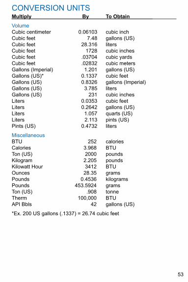
CONVERSION UNITSMultiply By To Obtain
VolumeCubic centimeter 0.06103 cubic inchCubic feet 7.48 gallons (US)Cubic feet 28.316 litersCubic feet 1728 cubic inchesCubic feet .03704 cubic yardsCubic feet .02832 cubic metersGallons (Imperial) 1.201 gallons (US)Gallons (US)* 0.1337 cubic feetGallons (US) 0.8326 gallons (Imperial)Gallons (US) 3.785 litersGallons (US) 231 cubic inchesLiters 0.0353 cubic feetLiters 0.2642 gallons (US)Liters 1.057 quarts (US)Liters 2.113 pints (US)Pints (US) 0.4732 liters
MiscellaneousBTU 252 caloriesCalories 3.968 BTUTon (US) 2000 poundskilogram 2.205 poundskilowatt Hour 3412 BTUOunces 28.35 gramsPounds 0.4536 kilogramsPounds 453.5924 gramsTon (US) .908 tonneTherm 100,000 BTUAPI Bbls 42 gallons (US)
*Ex. 200 US gallons (.1337) = 26.74 cubic feet
Mai
nten
ance
Log
Ser
ial N
umbe
r
Mfg
Dat
e
Dat
eM
ileag
eW
ork
Don
eTe
chni
cian
Initi
als
Nex
t Due


3181 Lear Drive Burlington, NC 27215 USAPhone (336) 226-3244 Fax (336) 227-6294
Manual LNG-545 Printed in the USA
www.regoproducts.com
Macro Technologies