Embed Size (px)
Citation preview
$25.00
Recommended Standard Specification
©2010 Web Sling & Tie Down Association, Inc.
For
Load Binders Used With
Chain Tie DownsWSTDA-T-6
DRAFT

© Web Sling & Tie Down Association. All rights reserved. No part of this publication may beproduced, stored in a retrieval system, or transmitted, in any form or by any means, electronic,mechanical, photocopying, recording or otherwise, without the prior permission of the Web Sling &Tie Down Association. This publication is circulated subject to the condition that it shall not, by wayof trade or otherwise, be lent, sold, hired out, or otherwise circulated without WSTDA's priorconsent.DRAFT
This Recommended Standard Specification applies to load binders designed to accommodate chain tie downs for the
purpose of securing cargo. This standard recommends construction as well as identification and marking of these load
binders. In addition, it gives important practical advice on the use, maintenance and inspection of these binders.
The exclusion from this Recommended Standard Specification of load binders, designed to accommodate chain tie downs
of different grades and capacities, is not intended to preclude their use and shall not be interpreted in this manner.
Load binders made from materials or construction other than those detailed in this Recommended Standard Specification
shall be used in accordance with the recommendations of the load binder manufacturer or qualified person. The
specifications contained in this Recommended Standard Specification for Load Binders used with Chain Tie Downs were
compiled under the auspices of the Web Sling & Tie Down Association, Inc. This Recommended Standard Specification is
intended to assist users in specifying the proper load binder for their particular requirements and to serve as a guide to the
industry in the construction and use of load binders, and also to serve as a guide to governmental and other regulatory
bodies responsible for the proper use and inspection of load binders used with chain tie downs. Illustrations included in
this document are for reference only and are not intended to depict or recommend any specific usage practice(s), design or
manufacturing process(s).
Safety is the paramount consideration involved in the use of any load binder designed to accommodate chain tie downs for
the purpose of securing cargo. This standard does not purport to address all safety concerns, if any, associated with its use. It
is the responsibility of the user of this standard to establish appropriate safety and health practices and determine the
applicability of the regulatory limitations prior to use. The appropriate load binder shall be selected by the user for their
specific application. Users of load binders designed to accommodate chain tie downs for the purpose of securing cargo
shall have knowledge on the proper method of cargo securement. Also users shall be knowledgeable about Federal, State,
Provincial, local and industry regulations applicable to cargo securement.
FOREWORD
WEB SLING & TIE DOWN ASSOCIATION, INC.2105 Laurel Bush Road, Suite 200
Bel Air, Maryland 21015
Phone (443) 640-1070
Email: [email protected]: www.wstda.com
First Published and Copyright 2010
MANDATORY AND ADVISORY RULESMandatory rules of this Recommended Standard Specification are characterized by the use
of the word “shall” If a rule is of an advisory nature, it is indicated by the use of the word
“should”, or is stated as a recommendation.
(443) 640-1031Fax
DRAFT
TABLE OF CONTENTS
Chapter 1.0 Terminology & Definitions
Chapter 2.0 Construction of Binders
Chapter 3.0 Standard Procedures for Testing Binders
Chapter 4.0 Recommended Operating Practices
Chapter 5.0 Standards Reference
Section 1.1 PurposeSection 1.2 Types of BindersSection 1.3 Definition of Terms
Section 2.1 PurposeSection 2.2 Lever Binder ComponentsSection 2.3 Low Energy Lever BindersSection 2.4 Ratchet BindersSection 2.5 Compression UnitsSection 2.6 MarkingsSection 2.7 Coatings
Section 3.1 PurposeSection 3.2 Types of TestsSection 3.3 Test Procedures to determine breaking strength
Section 4.1 PurposeSection 4.2 Proper SelectionSection 4.3 Use and CareSection 4.4 Environmental ConsiderationsSection 4.5 InspectionSection 4.6 Removal from ServiceSection 4.7 Repair of Binders
Section 5.1 ChainSection 5.2 Government Binder Specification (withdrawn)Section 5.3 FHWASection 5.4 FMCSASection 5.5 ASMESection 5.6 CVSADRAFT
1
Chapter 1.0 Terminology & Definitions
Lever Binder
Low Energy Release Lever Binders
Ratchet Binders
Compression Binder
1.1.1 This chapter provides terms and definitions as well as descriptions of binders which are
devices designed to be used with chain for the purpose of securing cargo.
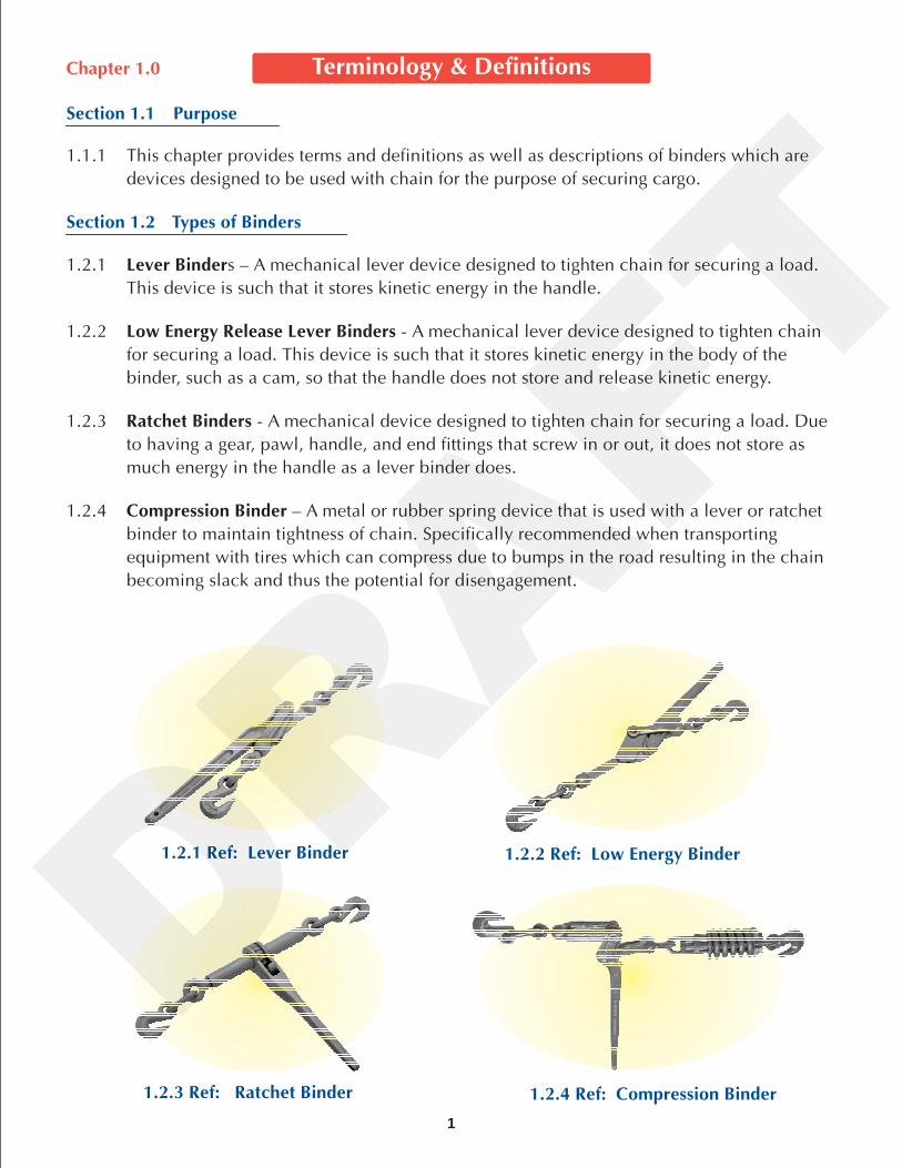
1.2.1 s – A mechanical lever device designed to tighten chain for securing a load.
This device is such that it stores kinetic energy in the handle.
1.2.2 - A mechanical lever device designed to tighten chain
for securing a load. This device is such that it stores kinetic energy in the body of the
binder, such as a cam, so that the handle does not store and release kinetic energy.
1.2.3 - A mechanical device designed to tighten chain for securing a load. Due
to having a gear, pawl, handle, and end fittings that screw in or out, it does not store as
much energy in the handle as a lever binder does.
1.2.4 – A metal or rubber spring device that is used with a lever or ratchet
binder to maintain tightness of chain. Specifically recommended when transporting
equipment with tires which can compress due to bumps in the road resulting in the chain
becoming slack and thus the potential for disengagement.
Section 1.1 Purpose
Section 1.2 Types of Binders
1.2.1 Ref: Lever Binder 1.2.2 Ref: Low Energy Binder
1.2.3 Ref: Ratchet Binder 1.2.4 Ref: Compression Binder
DRAFT
Section 1.3 Definition of Terms
Assembly Working Load Limit (WLL) -
Alloy Steel –
ASME –
ASTM – (
Binders –
Cast (or Die Cast) -
Commercial Vehicle Safety Alliance (CVSA) –
Compression Spring –
Deformation –
Design Factor –
EG Plating –
End Fittings –
Failure –
The total working load limit of a load securement system or
assembly, consisting of hooks, chain, and a binder. The assembly WLL is determined by the lowest WLL of
the three components.
steel to which one or more of the following alloying elements other than carbon
(i.e.: chromium, nickel, molybdenum, etc.) have been added to improve mechanical properties.
The American Society of Mechanical Engineers - One of the oldest standards-developing
organizations in the world, founded in 1880. As of 2006, it had 120,000 members. It produces
approximately 600 codes and standards, covering many technical areas, such as boiler components,
elevators, measurement of fluid flow in closed conduits, cranes, hand tools, fasteners, and machine tools.
Formerly “American Society for Testing and Materials”) - ASTM International is one of the largest
voluntary standards development organizations in the world, a trusted source for technical standards for
materials, products, systems, and services. Known for their high technical quality and market relevancy,
ASTM International standards have an important role in the information infrastructure that guides design,
manufacturing and trade in the global economy.
Binders referred to in this document are load binders. This would include lever style binders, low
energy binders, ratchet style binders & compression style binders (see section 1.2 ). They are not meant to
designate chain or any other component of a binding assembly.
Metal that has been heated to a melting point and formed by pouring the liquefied
metal into a mold. Gravity cast metal parts generally may be weaker and less ductile than forged parts of an
equivalent material.
Organization comprised of trucking companies, DOT
enforcement officials, and manufacturers that works with Canada, USA, and Mexico to harmonize
regulations and make recommendations on load securement procedures. CVSA out of service criteria is
used by all state and provincial enforcement officials to determine what is allowed and what is not
allowed.
A device used to absorb energy and keep chain from momentarily becoming slack.
Visible damage, distortion or misshaping of any component part.
The ratio of the minimum breaking strength (MBS) to the working load limit (WLL) for each
binder which shall meet or exceed the design factor of the chain being used as per NACM and ASTM.
A plating process of electrogalvanizing or electroplating that applies a zinc finish to metal
parts in order to inhibit rust and improve appearance. The plating may be treated to produce different
colored finishes.
Types of attachments on the ends of a lever or ratchet binder. Standard end fitting is a grab
hook, but other fittings such as a clevis jaw, claw hook or eye bolts can be used.
A breakdown in any binder component whereby additional load may not be applied.
2
DRAFT
3
Federal Motor Carrier Safety Administration (FMCSA) -
Forged – (or Drop Forged)
Gear –
Handle –
Hooks –
Markings –
Malleable -
Medium Carbon Steel (MC) –
Minimum Breaking Strength (MBS) -
The National Association of Chain Manufacturers (NACM) –
Pawl –
Proof Testing –
Tensile Load –
Trace Code –
Vehicle –
Working Load Limit (WLL) –
Wrap –
The U.S. government regulatory authority that is
the clearing house for all interstate trucking regulations and practices on the public highways, including
cargo securement specifically listed in 29 CFR Section 393.100 of the FMCSA regulation handbook.
The process where steel is heated and shaped via a forging hammer and a die.
The high pressures typical in forging result in a fine grain structure without the voids that can occur in
castings. Forging produces a product that will tend to yield or bend further before breaking compared to an
equivalent cast material. This provides an important notice to the user that the part has been loaded well
past the WLL and should be taken out of service.
The part of a ratchet binder that is engaged to the pawl.
The part of a binder by which it is held, moved, or operated to apply and release tension.
The part of the binder that is used to attach the binder to the chain, trailer, or load. It may be a
clevis grab hook, a claw hook, an eye grab hook, a slip hook or any combination thereof.
Letters or numbers indented or raised on a cast or forged part.
A metal or other material that can typically be shaped or bent at ambient temperatures without
breaking.
Steel with carbon content that is approximately in the range of 0.30% ~
0.59% containing less than 1.65% manganese and 0.60% silicon with no other specified alloying
elements.
The load or force in pounds or kilograms at which point any load
bearing part of the binders fails.
An organization representing North American
manufacturers of welded and weldless chain since 1933.
The component that engages and releases the gear on a ratchet binder to reverse direction of travel
on the end fittings.
Continuous testing procedure during production to identify quality issues.
The pulling force being applied expressed in pounds or kilograms.
Mark that allows the manufacturer to identify information on specific binder for quality and
testing results.
Any conveyance for carrying goods or equipment, such as a truck, trailer, van, container or
otherwise.
The maximum allowable load assigned to each binder by the manufacturer
which shall meet or exceed the WLL of the applicable trade size of chain, based on the design factor of the
chain being used as per NACM and/or ASTM.
One or more revolution of the non-load bearing portion of the chain around the binder.
DRAFT
4
Chapter 2.0 Construction of Binders
2.1.1 This chapter provides an outline of materials and construction characteristics of
binders designed to accommodate chain tie downs for the purpose of securing cargo.
Binders must be designed, constructed, and maintained so they can be tightened in
transit.
2.1.2 Basic load binder construction consists of a body, connecting eyes, connecting links,
hooks and a handle.
The minimum requirements for materials used to manufacture load binder component parts
should be as listed below:
2.2.1 Operating lever shall be of forged steel or cast MC steel, should not exceed 18½
inches (47cm) in length and should have a hole or knob in the lever end to be used to
secure the lever when in use.
2.2.2 Swivels shall be either malleable, upset forged alloy steel or drop forged MC steel.
2.2.3 Hooks shall be of high strength drop forged MC or alloy steel.
2.2.4 Clevis and tongue shall be of forged or cast MC or alloy steel.
2.2.5 Links shall be formed of either MC or alloy steel and welded with minimal flash.
2.2.6 Pins shall be of hardened MC or micro alloy steel.
The minimum requirements for materials used to manufacture load binder component parts
should be as listed below:
2.3.1 Operating lever shall be of forged steel or cast MC steel, should not exceed 18 ½
inches (47cm) in length and should have a hole or knob in the lever end to be used to
secure the lever when in use.
2.3.2 Swivels shall be either malleable, upset forged alloy or drop forged MC steel.
2.3.3 Hooks shall be of high strength drop forged MC or alloy steel.
2.3.4 Clevis and tongue shall be of forged or cast MC or alloy steel.
2.3.5 Links shall be formed of either MC or alloy steel and welded with minimal flash.
2.3.6 Cam may be of malleable iron, forged steel, or cast steel.
2.3.7 Pins shall be of hardened MC or micro alloy steel.
Section 2.1 Purpose
Section 2.2 Lever Binder Components
Section 2.3 Low Energy Lever Binders Components
DRAFT
5
Section 2.4 Ratchet Binders Components
Section 2.5 Compression Binders - Compression Units Components
Section 2.6 Markings
The minimum requirements for materials used to manufacture load binder component partsshould be as listed below:
2.4.1 Operating lever shall be of forged steel or cast MC steel, should not exceed 18 ½inches (47cm) in length, and should have a hole in the lever to be used to secure thelever when in use.
2.4.2 Hooks shall be of high strength, drop forged MC or alloy steel.
2.4.3 Links shall be formed of either MC or alloy steel and welded with minimal flash.
2.4.4 Pins shall be of hardened MC or micro alloy steel.
2.4.5 Pawl shall be of either die cast alloy or drop forged steel.
2.4.6 Gear shall be of either die cast alloy or drop forged steel.
2.4.7 Pawl shall be retained in place by either a spring, ball bearing or both.
(All other components of this binder shall remain the same as a lever binder, as per 2.2.)
2.5.1 Compression spring shall be made of spring steel
2.5.2 Compression unit shall be made of molded rubber.
2.6.1 Each binder shall be plainly marked with the manufacturer's designation of suchknown character that the source of manufacture may be readily determined.
2.6.2 Each binder shall be plainly marked with the WLL in pounds and/or kilograms. Loadbinders may also be marked with the applicable grade designation which wouldmatch the WLL of the chain being used as per the chain manufacturer. Chain gradedesignations that may be referenced on the binders are:
Grade 30 (Proof Coil Chain) identified by PC, 3, 30, or 300;Grade 43 (High Test Chain) identified by HT, 4, 43, or 430;Grade 70 (Transport Chain) identified by 7, 70, or 700;Grade 80 (Alloy Chain) identified by 8, 80 or 800;Grade 100 (Alloy Chain) identified by 10, 100 or 1000.
There may be a G for Grade, preceding the number. Binder hooks should beidentified (stamped or embossed) with the appropriate chain size(s) they are intendedto be used with.
2.6.3 Each binder shall be plainly marked with the Manufacturer's Name or Trademark.2.6.4 Each binder shall have a manufacturer's trace code or user identifiable date for
traceability.2.6.5 Warning label (see below) shall be attached to each binder.
WARNINGNever exceed the working load limit (WLL) of any load binder. Subjecting any load binder to loads beyondits WLL can result in severe personal injury or death. The design factor is based on destructive laboratorycontrolled testing conditions, which will not be exactly duplicated during actual loading & use.
DRAFT
6
Section 2.7 Coatings
Section 3.1 Purpose
Section 3.2 Types of Tests
Section 3.3 Test Procedures to Determine Breaking Strength
2.7.1 Binders should be coated to inhibit corrosion. When painted, the color shall be inaccordance with the manufacturer's standard practice or those specified by thecustomer and should not interfere with the normal operation of the binder.
3.1.1 This chapter provides standard procedures for testing binders designed toaccommodate chain for the purpose of securing cargo.
3.2.1 Testing shall be conducted after any and all electro or hot dip galvanizing or plating.
3.2.2 – Testing of preproduction binders shall be performed to establishthe minimum breaking strength (MBS) prior to production.
3.2.2.1 - A minimum of three (3) samples shall be tested to establish thebreaking strength of a load binder. The lowest test result shall be used todetermine the minimum breaking strength of the binder.
3.2.3 – Testing of production binders shall be performed for the purpose ofverifying the MBS.
3.2.3.1 Destructive testing of two (2) production binders from each lotof two thousand (2,000) or any part thereof. The MBS shall be equal to or exceedthe MBS as determined by the qualification tests and shall meet or exceed themanufacturers MBS for the size(s) and grade(s) of chain intended for used with thebinder. If one of the two binders fails the test, test two more. If those two passthen the production lot shall be accepted. If either of the second set of twobinders fails the test the lot shall be rejected.
3.2.3.2 All test machines shall be certified annually to ASTM E4 or equivalent standards.
3.2.4 – Every binder shall be proof tested during the manufacturingprocess, to a minimum of 2 times the WLL.
3.3.1 The only time the WLL should be exceeded is during testing.
3.3.2 Testing should be done with fixtures that simulate the load path and direction of theload application.
3.3.3 Testing of binders should be made with chain or fixtures that have a higher MBS thanthe ultimate strength of the binder being tested.
3.3.4 The tensile load shall be applied at a rate of 2 to 10 inches (50 to 250mm) per minuteor 100 to 1,000 lbs (45 to 450 kgs) per second until failure. The tensile load at failureis the breaking strength. Failure is the point at which additional load cannot beapplied.
3.3.5 Test results shall be kept on file by the manufacturer for a minimum of 7 years fromtest date.
3.3.6 The binder manufacturer or an independent testing laboratory shall perform thetesting.
3.3.7 All test machines shall be certified annually to ASTM E4 or equivalent standards.
Qualification Test
Destructive Test
Acceptance Test
Destructive Test -
Proof Testing
Chapter 3.0 Standard Procedures for Testing Binders
DRAFT
7
Chapter 4.0 Recommended Operating Practices
4.1.1 The purpose of this chapter is to provide guidelines to end users and enforcementpersonnel for the proper selection, use, and care, environmental considerations, andinspection of binders used in and for load securement.
4.2.1 All users must be trained in proper tie down selection, use and inspection, cautions topersonnel, environmental effects, all applicable standards, regulations and tie downpractices.
4.2.2 Select a binder having suitable characteristics for the specific load and thesecurement required. In order to achieve the required assembly working load limit(WLL), the hook, chain, load binder and the anchor point must be evaluated. Thecomponent with the lowest “WLL” shall be used to determine the assembly WLL forthe entire tie down assembly.
4.2.3 If the WLL or grade identifier of any of the three tie-down assembly components(excluding anchor points) is worn off, illegible, or missing, that product shall beremoved from service.
4.3.1 Binders shall not be loaded in excess of the WLL as provided by the manufacturer.
4.3.3 Before operating any binder the user shall secure their footing on the ground toprevent slipping or falling. In adverse weather conditions, including freezingtemperatures, additional caution should be exercised.
4.3.4 Binders should be matched with the equivalent grade of chain. Using the wrong gradeof binder or chain may reduce the assembly WLL of the securement system.
4.3.5 Lever binders shall always be released using an open hand with all body partscompletely out of the path that the handle travels.
4.3.6 Binders should be periodically checked and adjusted during transit to maintainproper tension. See 393.9 in FMCSA regulations.
4.3.7 Binders designed for load securement are not approved for overhead liftingapplications. Products for lifting require certification.
4.3.8 Handle extensions (cheater bars) shall not be used on any binders.
4.3.9 Regulations require each tie down to be attached and secured in a manner thatprevents it from becoming loose, unfastened, opened, or released while vehicle is intransit. Latches, chain wrap and/or other means should be used to secure binders andchain.
4.3.2 Handle extensions (cheater bars) should not be used on any binders. Binders developapproximate WLL tension with hand effort.
Section 4.1 Purpose
Section 4.2 Proper Selection
Section 4.3 Use and Care
DRAFT
8
Section 4.4 Environmental Considerations
4.4.1 Binders are subject to dirt, mud, snow, ice, road salt, cleaning solutions, etc. Bindersshould be periodically inspected, cleaned, and lubricated as needed to insureproper operation.
4.4.2 Binders not in use should be stored in a clean, dry location.
4.4.3 If binders have mud, snow, ice, etc in the gear or pivot points, drop forged bindersmay be struck with a hammer to break loose and remove any foreign material. Careshould be taken with binders manufactured with cast parts as striking with a hammer,especially in sub-freezing temperatures, may cause breakage.
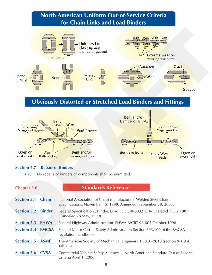
d. Clevis on pivot is worn, bent, distorted, or cracked.e. Pawl does not engage.f. Gear is worn, chipped, or cracked.g. Markings are missing, incomplete, illegible, or incorrect.h. Excessive rust.i. End fitting threads are worn, bent, distorted or will not turn.j. Bent or deformed handle.k. Swivel sockets and or ball worn or deformed.
4.5.1 Type of Inspection
4.5.1.1 Initial Inspection shall be made before a binder is placed into service to insure thebinder is being used for the application and that it matches the chain grade beingused.
4.5.1.2 Each time a binder is used it shall be inspected.
4.6.1 A binder shall be removed from service if any of the following conditions exist (and asper any and all CVSA removal from service criteria):
a. Hooks are worn, bent, distorted, twisted, stretched or cracked (ref. ASME B30.10)b. Links are bent, gouged, distorted, stretched, cracked or worn ((see wear allowances
per manufacturer, also specifications for wear on chain (links) and hooks can befound in ASME B30.9 section 9-1.9.4, Table 6)) and the NACM Welded Steel ChainSpecifications Table XVI. These and all manufacturer's specifications shall befollowed.
c. No welding on any component is allowed with the exception of the initialfactory production welds on the components during assembly.
Section 4.5 Inspection
Section 4.6 Removal from Service
DRAFT
9
Section 4.7 Repair of Binders
Section 5.1 Chain
Section 5.2 Binder
Section 5.3 FHWA
Section 5.4 FMCSA
Section 5.5 ASME
Section 5.6 CVSA
4.7.1 No repairs of binders or components shall be permitted.
National Association of Chain Manufacturers' Welded Steel Chain
Specifications, November 15, 1999, Amended: September 28, 2005.
Federal Specification , Binder, Load GGG-B-00325C (ME) Dated 7 July 1987
(Canceled 28 May, 1999)
Federal Highway Administration FHWA-MCRT-98-005 October 1998
Federal Motor Carrier Safety Administration Section 393.100 of the FMCSA
regulation handbook.
The American Society of Mechanical Engineers B30.9 –2010
Commercial Vehicle Safety Alliance - North American Standard Out of ServiceCriteria April 1, 2006
(section 9-1.9.4,
Table 6)
Chapter 5.0 Standards Reference
Obviously Distorted or Stretched Load Binders and Fittings
North American Uniform Out-of-Service Criteriafor Chain Links and Load Binders
DRAFT
U.S. Department of Transportation
Commercial Vehicle Safety Alliance
Specialized Carriers & Rigging Association
California Administrative Code:
Web Sling & Tie Down Association, Inc.
Federal Highway Administration (FHWA)
Federal Motor Carrier Safety Regulations
(FMCSR's, Title 49 of the Code of
Federal Regulations (CFR): Sections
392.9, Safe Loading; Part 393, Subpart 1
Protection Against Shifting or Falling Cargo).
Copies of 49 CFR Parts 200-399 may be
purchased from the U.S. Government Printing
Office, (202) 512-1800.
For questions concerning specific requirements
you can contact the Federal Highway
Administration, Office of Motor Carrier Research
and Standards ( HCS-10),
400 Seventh Street, SW
Washington, D.C., 20590
Phone (202) 366-4009
Fax (202) 366-8842
(CVSA) Cargo Securement Tie Down
Guidelines. Commercial Vehicle Safety
Alliance, 1101 17th Street NW, Suite 803
Washington, DC 20036
Phone (202) 775-1623
Fax (202) 775-1624
Cargo Securement on Motor Vehicles;
Steel Specialized Carriers & Rigging Assoc.,
2750 Prosperity Avenue, Suite 620,
Fairfax, VA 22031-4312
Phone (703) 698-0291
Fax (703) 698-0297
California Highway Patrol (CHP)
Title 13: Barclays Lay Publisher,
50 California St. 18th Floor
San Francisco, CA 94111-4624
Phone (800) 888-3600
Fax (415) 732-8861
Contact:
The Ministry of Transportation
in each Province.
Contact:
Director General de Transporte
Terreste Sub-Director de Inspection del Transporte
(Rep. En el C.V.S.A.)
Calzada de las Bombas Number 411-11- Piso
Col. San Bartolo Coapa
Mexico, D.F.C.P. 04500
2105 Laurel Bush Road, Suite 200
Bel Air, Maryland 21015
Phone (443) 640-1070
Fax (443) 640-1031
Email: [email protected]
Website: www.wstda.com
In Canada
In Mexico
ADDITIONAL RESOURCES
10
DRAFT
OTHER WEB SLING & TIE DOWN ASSOCIATION PUBLICATIONS
Training CD-Rom
North America Cargo Securement Standard WSTDA-CD-TP-2003
Illustrated Wall Chart
Inspection of Web Slings & Round Slings WSTDA-WSWC-1
UV Degradation Reports
Summary Report UV Degradation
UV Degradation Mini Manual
UV Degradation Report
WSTDA-UV-Sling-2003
WSTDA-UV-MM-2005
WSTDA-UVDR-1981 (Revised 2005)
WSTDA-WSV-1-CD
Video
Synthetic Web Sling Care & Inspection
Fabric Warning Labels
Web Slings
Tie Downs
Round Slings
WSWT-1
TDWT-1
RSWT-1
Paper Safety Bulletins
Web Slings
Roundslings
Tie Downs
WSSB-1
RSSB-1
TDSB-1
2105 Laurel Bush Road, Suite 200Bel Air, Maryland 21015Phone (443) 640-1070
Fax (443) 640-1031
Web Sling & Tie Down Association, Inc.
Email: [email protected] Site: www.wstda.com
For ordering information and prices, contact the association office or visit our website:
TM
WSTDA-WS-2
WSTDA-WS-PS-2
WSTDA-RS-2
WSTDA-RS-2-PS
WSTDA-T-2
WSTDA-T-2-PS
Operating & Inspection Manuals
Synthetic Web Slings
Synthetic Web Slings
Synthetic Polyester Roundslings
Synthetic Polyester Roundslings
Synthetic Web Tie Downs
Synthetic Web Tie Downs
(pocket sized)
(pocket sized)
(pocket sized)
Synthetic Web Slings
Synthetic Polyester Roundslings
Webbing for Synthetic Web Slings
Sewing Threads for Slings & Tie Downs
Synthetic Web Tie Downs
(French) Synthetic Web Tie Downs
Winches Used With Web Tie Downs
Synthetic Webbing Used for Tie Down
Load Binders Used with Chain Tie Downs
All Standards In A Three-Ring Binder
Synthetic Web Slings
Synthetic Polyester Roundslings
Webbing for Synthetic Web Slings
Sewing Threads for Slings & Tie Downs
Synthetic Web Tie Downs
(French) Synthetic Web Tie Downs
Winches Used With Web Tie Downs
Synthetic Webbing Used for Tie Downs
Load Binders Used with Chain Tie Downs
All Standards CD - (All above on one CD)
WSTDA-WS-1
WSTDA-RS-1
WSTDA-WB-1
WSTDA-TH-1
WSTDA-T-1
WSTDA-T-1
WSTDA-T-3
WSTDA-T-4
WSTDA-T-6
WSTDA-ASB-2006
WSTDA-SCD-WS-1
WSTDA-SCD-RS-1
WSTDA-SCD-WB-1
WSTDA-SCD-TH-1
WSTDA-SCD-T-1
WSTDA-SCD-T-1
WSTDA-SCD-T-3
WSTDA-SCD-T-4
WSTDA-T-6
WSTDA-ASCD-2006
Recommended Standard Specifications: Recommended Standard Specifications:
Printed Books PDF Files On CD
All Fabric Warning Labels and Safety Bulletins are availablein three languages; English, French and SpanishDRAFT

This recommended standard specification has been formulated as a guide to users, industry and governmentto ensure the proper use, maintenance and inspection of Load binders designed to accommodate chain tiedowns for the purpose of securing cargo. The existence of this recommended standard specification does not,however, prevent members of the Web Sling and Tie Down Association, Inc. and other manufacturers frommanufacturing or selling products not conforming to this standard.DRAFT