Embed Size (px)
Citation preview

With mechanical actuationWith electric remote control and mechanical actuationWith hydraulic remote control and mechanical actuation
Book 8 Partition 2 HK.57.B1.02
ydrique
Hy
k Hydraulics
aulique Hydraulik
H
aulik Hydraulics
Hydraul q
ue Hydraulik Hydraulics
Hydra
ulique Hydraulik
Hydraulics Hyd
Hydraulique Hydraulik
Hydraulics
aulics Hydraulique
Hydraulik Hy
Hydraulics Hydraulique
Hydraulik
aulik Hydraulics
Hydraulique Hy
ulique Hydraulik
Hydraulics Hyd
Hydraulique Hydraulik
Hydraulic
lique Hydraulik
Hydraulics Hydr
lics Hydraulique
Hydraulik
lik Hydraulics
Hydra
draulique Hydrau
draulics Hyd
lique
Catalogue
Load-independentProportional valveType PVG 32

Contents
2 HK.57.B1.02
Page
General 3
Function 4PVG 32 valve group 4Plug for external pilot oil supply, PVPC 6PVBS main spools for flow or pressure control 7Electrical LS unloading valve, PVPX 7
Technical data 8
Electric actuation 10
Modules and Pump side modules, PVP 13code numbers Basic valves, PVB - without LSA/B pressure limiting valves 15
Basic valves, PVB - with LSA/B pressure limiting valves 16Mechanical actuator, PVM 16Cover for mechanical actuation, PVMD 16Cover for hydraulic actuation, PVH 16Cover for friction detent, PVMR 16Cover for mechanical float position lock, PVMF 16Electrical actuator, PVE 17Suction valve, PVLA 17Shock and anti-cavitation valve, PVLP 18End plate, PVS, PVSI 18Assembly kit, PVAS 18Electrical LS unloading valve, PVPX 18Plug for external pilot oil supply, PVPC 19Main spools, PVBS 19
Technical characteristics 22
Dimensions 27
Hydraulic systems 29
Electrical systems 30
System safety 31
Other operating conditions 34
Module selection chart 35
Order specification 39
Conversion factors 40
The designation G for pipe threads replacesthe previous designation BSP.F cf. BS/ISO 228/1.
Thread designation
Contents

3
General
HK.57.B1.02
Valve systemPVG 32 is a hydraulic load sensing valvedesigned to give maximum flexibility. From asimple load sensing directional valve, to anadvanced electrically controlled load-independent proportional valve.
The PVG 32 module system makes it possibleto build up a valve group to meet requirementsprecisely.The compact external dimensions of the valveremain unchanged whatever combination isspecified.
General features PVG 32• Load-independent flow control:
- Oil flow to an individual function is independent of the load pressure of this function
- Oil flow to one function is independent of the load pressure of other functions
• Good regulation characteristics• Energy-saving• Up to 10 basic modules per valve group• Several types of connection threads• Low weight
PVG 32 valve group
Accessories Remote control units• Electrical remote control units
- PVRE, PVRET- PVREL- PVRES- Prof 1- Prof 1 CIP
• Hydraulic remote control unit- PVRHH
Electronics• Flow adjustment unit - EHF• Ramp generator - EHR• Speed control - EHS• Closed loop speed control - EHSC• Alarm logic - EHA• Closed loop position control - EHC• PVG CIP• CIP Configuration Tool
Pump side module - PVP• Built-in pressure relief valve• System pressure up to 300 bar continuous
and 320 bar intermittent• Pressure gauge connection
• Versions:- Open centre version for systems with fixed
displacement pumps- Closed centre version for systems with
variable displacement pumps- Pilot oil supply for electrical
actuator built into the pump side module- Versions prepared for electrical LS
unloading valve PVPX
Basic module - PVB• Interchangeable spools• Depending on requirements the basic
module can be supplied with:- Integrated pressure compensator in
channel P- Check valve in channel P- Shock/suction valves- LS pressure limiting valves individually
adjustable for ports A and B- Different spool variants
Actuation modulesThe basic module is always fitted with mecha-nical actuator PVM, which can be combinedwith the following as required:
• Electrical actuator (12 V or 24 V )- PVES - proportional, super- PVEH - proportional, high performance- PVEM - proportional, medium
performance- PVEO - ON/OFF
• Cover for mechanical actuation, PVMD• Cover for mechanical detent, PVMR• Cover for mechanical float, PVMF• Cover for hydraulic actuation, PVH

Function
4 HK.57.B1.02
PVG 32 valve group withopen centre PVP(PVB with flow controlspool)
PVG 32 valve group withclosed centre PVP(PVB with flow controlspool)
When the pump is started and the main spoolsin the individual basic modules (11) are in theneutral position, oil flows from the pump, through connection P, across the pressure adjustment spool (6) to tank. The oil flow ledacross the pressure adjustment spool determines the pump pressure (stand-by pressure).
When one or more of the main spools are actuated, the highest load pressure is fed thro-ugh the shuttle valve circuit (10) to the springchamber behind the pressure adjustment spool (6), and completely or partially closes the connection to tank.
Pump pressure is applied to the right-handside of the pressure adjustment spool (6). Thepressure relief valve (1) will open should theload pressure exceed the set value, divertingpump flow back to tank.
In a pressure-compensated basic module thecompensator (14) maintains a constant pressure drop across the main spool - bothwhen the load changes and when a modulewith a higher load pressure is actuated.
With a non pressure-compensated basicmodule incorporating a load drop check valve(18) in channel P, the check valve preventsreturn oil flow.The basic module can be supplied without theload drop check valve in channel P for functions with over-centre valves.
The shock valves PVLP (13) with fixed setting and the suction valves PVLA (17) onports A and B are used for the protection ofthe individual working function against overload and/or cavitation.
An adjustable LS pressure limiting valve (12)can be built into the A and B ports of pressure-compensated basic modules to limit the pressure from the individual working functions.
The LS pressure limiting valves save energycompared with the shock valves PVLP:- With PVLP all the oil flow to the
working function will be led across the combined shock and suction valves to tank if the pressure exceeds the fixed setting.
- With LS pressure limiting valves an oil flow of about 2 l/min will be led across the LS pressure limiting valve to tank if the pressure exceeds the valve setting.
In the closed centre version an orifice (5) anda plug (7) have been fitted instead of the plug(4). This means that the pressure adjustmentspool (6) will only open to tank when the pressure in channel P exceeds the set valueof the pressure relief valve (1).
In load sensing systems the load pressure is led to the pump regulator via the LS connection (8).
In the neutral position the pump control setsthe displacement so that leakage in thesystem is compensated for, to maintain the setstand-by pressureWhen a main spool is actuated the pumpregulator will adjust the displacement so thatthe set differential pressure between P and LSis maintained.
The pressure relief valve (1) in PVP should beset at a pressure of approx. 30 bar abovemaximum system pressure (set on the pumpor external pressure relief valve).

Function
5HK.57.B1.02
Sectional drawing, PVG
1. Pressure relief valve2. Pressure reduction valve
for pilot oil supply3. Pressure gauge connection4. Plug, open centre5. Orifice, closed centre6. Pressure adjustment spool7. Plug, closed centre8. LS connection9. LS signal
10. Shuttle valve
PVP
PVB
PVB
11. Main spool12. LS pressure limiting valve13. Shock and suction valve, PVLP14. Pressure compensator15. LS connection, port A16. LS connection, port B17. Suction valve, PVLA18. Load drop check valve19. Pilot oil supply for PVE20. Max. oil flow adjustment screws for
ports A and B

Function
6 HK.57.B1.02
PVPC with check valve
PVPC with check valve for open centre PVPPVPC with check valve is used in systems where it is necessaryto operate the PVG 32 valve by means of the electrical remotecontrol without pump flow. When the external solenoid valve isopened, oil from the pressure side of the cylinder is fed via thePVPC through the pressure reducing valve to act as the pilot supply for the electrical actuators. This means that a load can belowered by means of the remote control lever without starting thepump. The built-in check valve prevents the oil from flowing viathe pressure adjustment spool to tank. With the pump functioningnormally the external solenoid valve is closed to ensure that theload is not lowered due to the pilot supply oil flow requirement ofapproximately 1 l/min.
Please note:With closed centre PVP the external pilot oil supply can be connected to the pressure gauge connection without the use of aPVPC plug.
PVPC
PVPC without check valve for open or closed centre PVPPVPC without check valve is used in systems where it is necessary to supply the PVG 32 valve with oil from a manually operated emergency pump without directing oil flow to the pilot oilsupply (oil consumption about 1 l/min).
When the main pump is working normally, the oil is directed through the PVPC plug via the pressure reduction valve to the electrical actuators.
When the main pump flow fails, the external shuttle valve ensures that the oil flow from the manually operated emergencypump is used to pilot open the over centre valve and lower the load.The load can only be lowered using the mechanical operating leverof the PVG 32 valve.
Plug for external pilot oil supply, PVPC
PVPC without check valve
Function
7HK.57.B1.02
PVBS, PVPX
PVBS main spools for flowcontrol (standard)
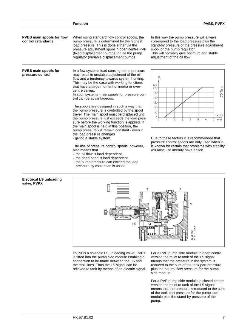
In this way the pump pressure will always correspond to the load pressure plus thestand-by pressure of the pressure adjustmentspool or the pump regulator.This will normally give optimum and stableadjustment of the oil flow.
When using standard flow control spools, thepump pressure is determined by the highestload pressure. This is done either via the pressure adjustment spool in open centre PVP (fixed displacement pumps) or via the pumpregulator (variable displacement pumps).
Due to these factors it is recommended thatpressure control spools are only used when itis known for certain that problems with stabilitywill arise - or already have arisen.
Electrical LS unloadingvalve, PVPX
PVBS main spools forpressure control
PVPX is a solenoid LS unloading valve. PVPXis fitted into the pump side module enabling aconnection to be made between the LS andthe tank lines. Thus the LS signal can be relieved to tank by means of an electric signal.
For a PVP pump side module in open centre version the relief to tank of the LS signal means that the pressure in the system is reduced to the sum of the tank port pressure plus the neutral flow pressure for the pump side module.
For a PVP pump side module in closed centreversion the relief to tank of the LS signalmeans that the pressure is reduced to the sumof the tank port pressure for the pump sidemodule plus the stand-by pressure of thepump.
In a few systems load sensing pump pressuremay result in unstable adjustment of the oilflow and a tendency towards system hunting.This may be the case with working functionsthat have a large moment of inertia or over-centre valves.In such systems main spools for pressure con-trol can be advantageous.
The spools are designed in such a way thatthe pump pressure is controlled by the spooltravel. The main spool must be displaced untilthe pump pressure just exceeds the load pres-sure before the working function is applied. Ifthe main spool is held in this position, thepump pressure will remain constant - even ifthe load pressure changes - giving a stable system.
The use of pressure control spools, however,also means that- the oil flow is load dependent- the dead band is load dependent- the pump pressure can exceed the load
pressure by more than is usual.

Technical data
8 HK.57.B1.02
Regulation standard control lever ± 19,5°
Regulation range, Proportional range ± 13,4°float position control lever Float position 22,3°
Neutral- Max. spoolposition travel
Operating force PVM + PVMD 2,2 ± 0,3 daN 2,8 ± 0,3 daN
PVM + PVE 1) 2,2 ± 0,3 daN 2,8 ± 0,3 daN
PVM + PVH 2,7 ± 0,3 daN 8,3 ± 0,3 daN
Control lever positions, see page 28 No. 2 × 6
continuous 300 bar 2)
Port Pintermittent 1) 320 bar 2)
Max pressurePort A/B 350 bar
Port T, static/dynamic 25 bar/40 bar
Port P 140 l/min 4)
Oil flow, ratedPort A/B, with press. comp. 100 l/min 3)
(See characteristics, page 22 - 24)Port A/B , without press. comp. 125 l/min
Spool travel, standard ± 7 mm
Proportional range ± 4,8 mmSpool travel, float position spool
Float position 8 mm
Dead band, flow control spools ± 1,5 mm
Max. internal leakage A/B → T, without shock valve 20 cm3/minat 100 bar and 21 mm2/s A/B → T, with shock valve 25 cm3/min
Recommended temperature 30 → 60°COil temperature (inlet temperature) Min. temperature −30°C
Max. temperature +90°CAmbient temperature −30 → +60°C
Operating range 12 - 75 mm2/s
Oil viscosity Min. viscosity 4 mm2/s
Max. viscosity 460 mm2/s
Filtration Max. contamination19/16(See page 34) (ISO 4406)
Oil consumption in pilot oil pressure reduction valve 1 l/min
Regulation range 5-15 bar
Max. pilot pressure 30 bar
Max. pressure on port T 1) 10 bar
Technical data
Hydraulic actuation PVH
The technical data for PVG 32 and PVPX aretypical measured results. For the hydraulicsystem a mineral based hydraulic oil with aviscosity of 21 mm2/s and a temperature of50°C was used.
Valve group PVG 32
1) The PVRHH remote control lever should be connected direct to tank.
Mechanical actuation PVM
1) PVE without voltage
1) Max. 10% operation every minute2) With PVSI end plate3) For 130 l/min contact technical Sales Organization for Danfoss Hydraulics4) In open circuit systems with short P-hoses/tubes, attention should be paid to pressure peaks at flows >100l/min.

Technical data
9HK.57.B1.02
PVE, PVPX
Actuator PVEO, PVEM, PVEH and PVES
Rated voltage 12 V 24 V
Voltage range 11-15 V 22-30 VSupply voltage (UDC)
Max. ripple 5%
Current consumption 3) 0,65 A 0,33 A
Neutral 0,5 × UDCSignal voltage (PVEM/PVEH/PVES) Control range 0,25 × UDC to 0,75 × UDC
Signal current 3) (PVEM/PVEH/PVES) 0,25 mA 0,5 mA
Input impedance in relation 0,5 × UDC 12 kΩPower consumption 8 W
Max. load − 100 mA − 60 mA
Fault monitoring (PVEH/PVES) Active Reaction time at fault 500 ms
Passive Reaction time at fault 250 ms3) at rated voltage
Electrical LS unloading valve PVPX
Max. operation pressure 350 bar
Max. pressure drop at an oil flow of 10 l/min 2 bar
Recommended temperature 30 - 60°COil temperature Min. temperature − 30°C(inlet temperature)
Max. temperature + 90°CMax. coil surface temperature 155°CAmbient temperature −30 → +60°C
Operating range 12 → 75 mm2/s
Oil viscosity Min. viscosity 4 mm2/s
Max. viscosity 460 mm2/s
Response time for LS pressure relief 300 ms
Enclosure to IEC IEC 529 IP 65
Rated voltage 12 V 24 V
Max.permissible deviation from rated supply voltage ± 10%
Current consumption at rated voltageAt 22°C coil temperature 1,55 A 0,78 A
At 110°C coil temperature 1,00 A 0,50 A
At 22°C coil temperature 19 W 19WPower consumption
At 110°C coil temperature 12 W 12 W
Electrical actuation PVE
1) Hysteresis is indicated at rated voltage and f = 0.02 Hz for one cycle. A cycle incl. N > full A > N > full B > N.
PVEOPVEM PVEH PVES
Voltage FunctionON/OFF
Prop. Prop. Prop.medium high high
Reaction time from neutral position Max. 0,235 s 0,700 s 0,230 s 0,230 s
Neutral switchto max. spool travel
Rated 0,180 s 0,450 s 0,150 s 0,150 s
Min. 0,120 s 0,230 s 0,120 s 0,120 s
Max. 0,175 s 0,175 s 0,175 s 0,175 s
Neutral switchReaction time from max. spool travel
Rated 0,090 s 0,090 s 0,090 s 0,090 sto neutral positionMin. 0,065 s 0,065 s 0,065 s 0,065 s
Max. 0,700 s 0,200 s 0,200 s
Constant voltageReaction time from neutral position
Rated 0,450 s 0,120 s 0,120 sto max. spool travelMin. 0,230 s 0,050 s 0,050 s
Max. 0,700 s 0,100 s 0,100 s
Constant voltage Reaction time from max. spool travel Rated 0,450 s 0,090 s 0,090 sto neutral positionMin. 0,230 s 0,065 s 0,065 s
Without voltage Pilot oil flow per PVE Neutral 0 l/min 0 l/min 0 l/min 0,4 l/min
Locked 0,1 l/min 0,1 l/min 0,1 l/min 0,2 l/min
With voltage Pilot oil flow per PVE 1 actuation 0,002 l 0,002 l 0,002 l 0,002 l
Actuations 0,7 l/min 0,5 l/min 1,1 l/min 1,1 l/min
Hysteresis 1) Rated 20% 4% <1%
Grade of enclosure IEC 529 IP65

Electrical actuation
10 HK.57.B1.02
Proportional actuation
PVEM, Proportional medium
PVEH, Proportional high
PVEM versions are recommended where there is a requirement for simple proportionalcontrol and where reaction and hysteresis arenot critical. Main features of PVEM:
• ON-OFF modulated• Inductive transducer, see page 11• Medium hysteresis
With electrical proportional actuation the mainspool position is adjusted so that it corresponds to an electric signal - from aremote control unit, for example.
The signal (set-point signal) is converted intoa hydraulic pressure which moves the mainspool. The position of the main spool is
converted in the positional transducer (C) to an electric signal (feed-back signal). This signal is registered by the electronics.The variation between the set-point signal andfeed-back signal actuates the solenoid valves.The solenoid valves are actuated so thathydraulic pressure moves the main spool intothe correct position.
Main features of PVEO:
• Compact• Robust operation • Simple build-up
ON-OFF actuation
PVEH versions are recommended whereamong the requirements are fault monitoring,fast system reaction, low hysteresis and fineregulation. Main features of PVEH:
• Inductive transducer, see page 11• Integrated pulse width modulation, see
page 11• Short reaction time• Low hysteresis• Fault monitoring, see page 11 and 12• Transistor output for signal source, see
page 12 PVES, Proportional super
PVES versions are recommended for controlsystems requiring very low hysteresis to obtain a very fine regulation. For other technical data: see PVEH.
PVEO, ON-OFF

Electrical actuation
11HK.57.B1.02
PVE
The fault monitoringsystem
Active fault monitoring:- A delay of 500 ms before anything
happens.- The solenoid valve bridge will be disabled, -
all solenoids will be released.- An alarm signal is sent out through the
connector.- This state is memorized and continues until
the system is actively reset (by turning offthe supply voltage).
Passive fault monitoring:- A delay of 250 ms before anything
happens. - An alarm signal is sent out through the
connector.- This state is not memorized. When the
erroneous state disappears, the alarmsignal will turn to passive again. However,the signal will always be active for aminimum of 100 ms when triggered.
To prevent the electronics from going into anundefined state, a general supervision of thepower supply and the internal clock frequencyis made. This function applies to PVEH, PVESand PVEM:
High supply voltage: The solenoid valves are disabled when thesupply voltage is exceeded by 50% (18 V for a12 V PVE and 36 V for a 24 V PVE).
Low supply voltage: The solenoid valves are disabled when thesupply voltage falls below 8 V.
Internal clock: The solenoid valves are disabled when theinternal clock frequency fails.All three states are triggered automaticallywhen the fault conditions cease.
Note:1. Different degrees of safety are
described on pages 31 to 33.
2. The fault monitoring does not work if the supply voltage to PVEH/PVES is cut off - for example by a neutral position switch (see page 31).
3. When using PVEH/PVES with passive fault monitoring it’s up to the customer to decide on the required degree of safety for the system (see page 31).
A fault monitoring system is provided in allPVEH and PVES models. The system isavailable in two versions: – The active faultmonitoring type, which provides a warningsignal and deactivates the solenoid valves,and the passive fault monitoring type, whichprovides a warning signal only. See figurebelow.Both active and passive fault monitoringsystems are triggered by three main events:
Input signal monitoring: The input signal voltage is continuouslymonitored. The permissible range is between15% and 85% of the supply voltage. Outsidethis range the section will switch into an activeerror state.
Transducer supervision: If one of the wires to the LVDT sensor isbroken or short-circuited, this section willswitch into an active error state.
Supervision of the closed loop: The actual position must always correspond tothe demanded position (input signal). Whenthe distance from neutral to the actual positionis longer than the demanded distance, thesystem detects an error and will switch into anactive error state. On the other hand, asituation where the actual position is closer toneutral than that demanded will not cause anerror state. This situation is considered “incontrol”.When an active error state occurs, the faultmonitoring logic will be triggered:Note:The neutral deadband prevents the outputsignal from releasing the fault monitoring logic,thus stopping the function until the requiredpilot oil pressure has been developed.
LVDT-transducer, pulsewidth modulation
Inductive transducer, LVDT(Linear Variable Differential Transformer).When the main spool is moved, a voltage isinduced proportional to the spool position. Theuse of LVDT gives contact-free (proximity)registration of the main spool position. Thismeans an extra-long working life and nolimitation as regards the type of hydraulic fluidused. In addition, LVDT gives a preciseposition signal of high resolution.
Integrated pulse width modulationPositioning of the main spool in PVEH isbased on the pulse width modulation principle.
As soon as the main spool reached therequired position, modulation stops and thespool is locked in position.

Electrical actuation
12 HK.57.B1.02
PVEH/PVES - connectionto fault monitoring output
Transistor output function
Example of connected components Example of connected components
A: External relayB: Solenoid valve (e.g. PVPX)
A: External relayB: Solenoid valve (e.g. PVPX)
Other connections possible:- a solenoid valve to relieve the pump oil flow- a signal lamp, an alarm horn- pump cut-out, etc.
Via an external relay the pin pos. 3 can be connected to a solenoid valve which will relieve the LS-signal to tank, e.g. PVPX.
Normal operation (green light) Fault cut-out (red light)
Transistor output function

13HK.57.B1.02
Modules and code numbers
Pump side modules, PVP
Connection: P = G 1/2; 14 mm deep or G 3/4; 16 mm deep. LS/M = G 1/4; 12 mm deep; T = G 3/4; 16 mm deep.
ISO-symbol DescriptionCode number
P = G 1/2 P = G 3/4
Open centre pump side module for pumps with fixed displacement.
157B5000 157B5100For purely mechanically actuated valve groups.
Open centre pump side module for pumps with fixed displacement.
With pilot oil supply. 157B5010 157B5110
For electrically actuated valves.
Open centre pump side module for pumps with fixed displacement.
With pilot oil supply.157B5012 157B5112
For electrically actuated valves.
Connection for electricalLS unloading valve, PVPX.
Closed centre pump side module forpumps with variable displacement.
157B5001 157B5101For purely mechanically actuated valve groups.
Closed centre pump side module forpumps with variable displacement.
With pilot oil supply. 157B5011 157B5111
For electrically actuated valves.
Closed centre pump side module forpumps with variable displacement
With pilot oil supply.157B5013 157B5113
For electrically actuated valves.
Connection for electricalLS unloading valve, PVPX.

Modules and code numbers
14 HK.57.B1.02
Pump side modules, PVP
ISO-symbol DescriptionCode number
P = G 1/2 P = G 3/4
Open centre pump side module for pumps with fixed displacement.
For mechanically actuated 157B5102valves.
Connection for LS unloading valve, PVPX.
Closed centre pump side module forpumps with variable displacement.
For mechanically actuated 157B5103valves.
Connection for LSunloading valve, PVPX.
Open centre pump side module for pumps with fixed displacement.
With pilot oil supply for hydraulic actuation and connection for pilot 157B5180 oil pressure.
For electrical actuated valves.
Open centre pump side module for pumps with fixed displacement.
With pilot oil supply for hydraulic 157B5190actuation and connection for pilot
oil pressure.
For hydraulic actuated valves.
Closed centre pump side module forpumps with variable displacement.
With pilot oil supplyfor hydraulic 157B5191actuation and connection for pilot
oil pressure.
For hydraulic actuated valves.
Connection: P = G 1/2; 14 mm deep or G 3/4; 16 mm deep. LS/M = G 1/4; 12 mm deep; T = G 3/4; 16 mm deep.
PVP

15
Modules and code numbers
HK.57.B1.02
PVB
Basic modules, PVB - without adjustable LS A/B pressure limiting valves
Connection: Port A/B: G 1/2, 14 mm deep
Without load drop check valve andpressure compensator.Can be used where load holding 157B6000 157B6030valves prevent oil from flowing backthrough channel P.
Load drop check valve. 157B6100 157B6130
Load drop check valve.LSA/B shuttle valve.
157B6136To be used withfloat position spools.
With non-damped compensator valve. 157B6200 157B6230
With damped compensator valve. 157B6206 157B6236
Code number
ISO-symbol Description No facilities for Facilities for shock valves shock valves
A/B A/B

ISO-symbol Description Code numberAngle
on base
Standard, spring centered. 157B3171 22.5°Individual oil flow adjustment to ports A and B 157B3172 37.5°
As standard, without actuation lever. 157B3174 37.5°With base for mounting of actuation lever. 157B3175 22.5°
As standard, without actuation lever and base.157B3173 -Shaft for mounting of actuation lever.
Cover for purely mechanically operated valve. 157B0001
Cover for hydraulic remote control, PVH 157B0008
Friction detent, PVMR 157B0004
Mechanical float position lock, PVMF 157B0005
16
Code number
ISO-symbol Description No facilities Facilities forfor shock valves shock valves
A/B A/B
Modules and code numbers
HK.57.B1.02
PVB, PVM, PVMD, PVH, PVMR, PVMF
Mechanical actuator, PVMCover, PVMDCover, PVHCover, PVMRCover, PVMF
Connections: Port A/B: G 1/2; 14 mm deep. LSA/B: G 1/4; 12 mm deep.
Basic modules, PVB - with adjustable LS A/B pressure limiting valves
With non-damped.compensator valve.Adjustable LSA/Bpressure limiting valves.
157B6203 157B6233External LS connectionport A/B.Also used for float position spools.
Damped compensator valve.Adjustable LSA/B pressure limitingvalves. 157B6208 157B6238External LS connectionport A/B.
Connections: PVH: G 1/4; 12 mm deep.

Modules and code numbers
17HK.57.B1.02
Electrical actuator, PVEISO-symbol Description
Code number
12 V 24 V
PVEO 157B4216 157B4228ON/OFF
PVEM, standard. Proportional Medium 157B4116 157B4128On/Off-modulated, inductive transducer.
PVEM for float position. Proportional Medium. 157B4416 157B4428On/Off-modulated, inductive transducer etc.
PVEH, standard. Proportional High. Pulse-widthmodulation, quick response, low hysteresis, 157B4016 157B4028active fault monitoring, inductive transducer.
PVEH. Proportional High. Pulse widthmodulation, quick response, low hysteresis, 157B4086 157B4088passive fault monitoring, inductive transducer.
PVEH for float position. Proportional High. Pulse width modulation, quick response low hysteresis, 157B4316 157B4328active fault monitoring,inductive transducer etc.
PVES. Proportional super. 157B4816 157B4828Specifications as PVEH but hysteresis ~ 0%
PVE, PVLA
Suction valve, PVLA (fitted in PVB)
ISO-symbol Description Code number
Suction valve157B2001port A and/or B.
Plug for connecting thenonactive port to tank,when using a single 157B2002acting spool

ISO-symbol Description Setting Code(bar) number32 157B203250 157B205063 157B206380 157B2080100 157B2100125 157B2125140 157B2140
Shock- and 150 157B2150suction valve 160 157B2160for port A and B. 175 157B2175Not adjustable. 190 157B2190
210 157B2210230 157B2230240 157B2240250 157B2250280 157B2280300 157B2300320 157B2320
Modules and code numbers
18 HK.57.B1.02
End plate, PVS
PVLP, PVS, PVAS, PVPX
Shock and suction valve, PVLP (fitted in PVB)
ISO-symbol Description Code number
PVSWithout active elements. 157B2000No connections
PVSWithout active elements. 157B2011Max. intermittent LX pressure: 250 bar
PVSI Without active elements. 157B2014Without connections
PVSIWithout active elements. 157B2015LX connections. Max. int. LX pressure: 320 bar
LX connection: PVS; G 1/8, 10 mm deepPVSI; G 1/4, 12 mm deep
Electrical LS unloadingvalve, PVPX
Code numberDescription
1 PVB 2 PVB 3 PVB 4 PVB 5 PVB 6 PVB 7 PVB 8 PVB 9 PVB 10 PVB
Tie bolts and seals 157B8001 157B8002 157B8003 157B8004 157B8005 157B8006 157B8007 157B8008 157B8009 157B8010
Assembly kit, PVAS
ISO-symbol DescriptionCode number
12 V 24 V
Normally open: 157B4236 157B4238LS pressure relieved with no signal to PVPX.
Normally closed:157B4246 157B4248LS pressure relieved with signal to PVPX.
Normally open with manual override:LS pressure relieved with no signal to PVPX. 157B4256 157B4258Manual over-ride DE-selects LS-pump
Plug 157B5601

Modules and code numbers
19HK.57.B1.02
ISO-symbol Description Code number
Plug without check valve for157B5400open or closed centre PVP
Plug with check valve 157B5600
for open centre PVP
PVPC, PVBS
Plug for external pilot oil supply, PVPC
PVBS main spools for hydraulically actuated basic modules without LS A/B shuttle valve
Connection: G 1/2, 12 mm deep
1) Oil flow applies to flow control spools only.2) PC = Pressure control
For basic modules with LSA/B shuttle valve
Code number
Symbol ISO-symbol DescriptionSize and pressure-compensated oil flow 1)
A B C D E
10 l/min 25 l/min 40 l/min 65 l/min 100 l/min
4-way, 3-position.Closed neutral position. 157B9000 157B9001 157B9002 157B9003 157B9004Flow control.
4-way, 3-position.Throttled, open neutral position. 157B9100 157B9101 157B9102 157B9103 157B9104Flow control.
4-way, 3-positionClosed neutral position. 157B9010 157B9011 157B9012Pressure control (PC → A and B).2)
Code number
Symbol ISO-symbol DescriptionSize and pressure-compensated oil flow
AA A B C D E
5 l/min 10 l/min 25 l/min 40 l/min 65 l/min 100 l/min
4-way, 3 position.Closed neutral position. 157B9025 157B9020 157B9021 157B9022 157B9023 157B9024Flow control.
4-way, 3 position.Throttled, open neutral position. 157B9125 157B9120 157B9121 157B9122 157B9123 157B9124Flow control.

Modules and code numbers
20 HK.57.B1.02
PVBS, main spools for flow control
PVBS
For basic modules with LSA/B shuttle valve
For basic modules without LSA/B shuttle valve
Code number
Symbol ISO-symbol DescriptionSize and pressure-compensated oil flow
AA A B C D E F
5 l/min 10 l/min 25 l/min 40 l/min 65 l/min 100 l/min 130 l/min
4-way, 3-position.Closed neutral 157B7005 157B7000 157B7001 157B7002 157B7003 157B7004 157B7006
position
4-way, 3-position.Throttled, open 157B7105 157B7100 157B7101 157B7102 157B7103 157B7104 157B7106neutral position.
3-way, 3-position.Closed neutral 157B7200 157B7201 157B7202 157B7203 157B7204position P → A
3-way, 3-position.Closed neutral 157B7301 157B7302 157B7303 157B7304position P → B
4-way, 3-position.
A → T 157B7401 157B7402 157B7403 157B7404 157B7406in neutral position.
4-way, 3-positionB → T 157B7501 157B7502 157B7503 157B7504in neutral position.
Code number
Symbol ISO-symbol DescriptionSize and pressure-compensated oil flow
AA A B C D E F
5 l/min 10 l/min 25 l/min 40 l/min 65 l/min 100 l/min 130 l/min
4-way, 3-position.Closed neutral 157B7025 157B7020 157B7021 157B7022 157B7023 157B7024 157B7026position.
4-way, 3-position.Throttled, open 157B7125 157B7120 157B7121 157B7122 157B7123 157B7124 157B7126neutral position.
4-way, 3-position.A → T 157B7421 157B7422 157B7423 157B7424in neutral position.
4-way, 3-position.B → T 157B7521 157B7522 157B7523 157B7524in neutral position.
4-way, 4-position.For float position 157B7620 157B7621 157B7622 157B7623 157B7624P → B → F

Modules and code numbers
21HK.57.B1.02
PVBS
PVBS, main spools forpressure control
For basic modules without LSA/B shuttle valve
PC = Pressure control
PC = Pressure control
For basic modules with LSA/B shuttle valve
Code number
Symbol ISO-symbol Description Size
AA A B C D E
4-way, 3 position.Closed neutral position. 157B7015 157B7010 157B7011 157B7012 157B7013PC →A and B
4-way, 3 position.Open neutral position. 157B7115 157B7110 157B7111 157B7112 157B7113PC → A and B
4-way, 3 position.Closed neutral position. 157B7040 157B7041 157B7042 157B7043 157B7044PC →A
4-way, 3 position.Closed neutral position. 157B7051 157B7052 157B7053 157B7054PC → B4-way, 3 position.Throttled, open neutral position. 157B7141 157B7142 157B7143 157B7144PC →A
4-way, 3 position.Throttled, open neutral position. 157B7150 157B7151 157B7152 157B7153 157B7154PC → B4-way, 3 position.A → T neutral position. 157B7452 157B7453PC → B
4-way, 3 positionB →T neutral position. 157B7541 157B7542 157B7543PC → A
Code number
Symbol ISO-symbol Description Size
AA A B C D E
4-way, 3 position.Closed neutral position. 157B7030 157B7031 157B7032 157B7033PC → A and B
4-way, 3 position.Open neutral position. 157B7135 157B7130 157B7131 157B7132PC → A & B
4-way, 3 position.Closed neutral position. 157B7061 157B7062 157B7063 157B7064PC → A
4-way, 3 position.Closed neutral position. 157B7071 157B7072 157B7073 157B7074PC → B4-way, 3 position.Throttled, open neutral position. 157B7161 157B7162 157B7163 157B7164PC → A4-way 3 position.open neutral position. 157B7171 157B7172 157B7173 157B7174PC → B
4-way, 3 position.A → T neutral position. 157B7472 157B7473PC →B
4-way, 3 position.B → T neutral position. 157B7562 157B7563PC → A
Technical characteristics
22 HK.57.B1.02
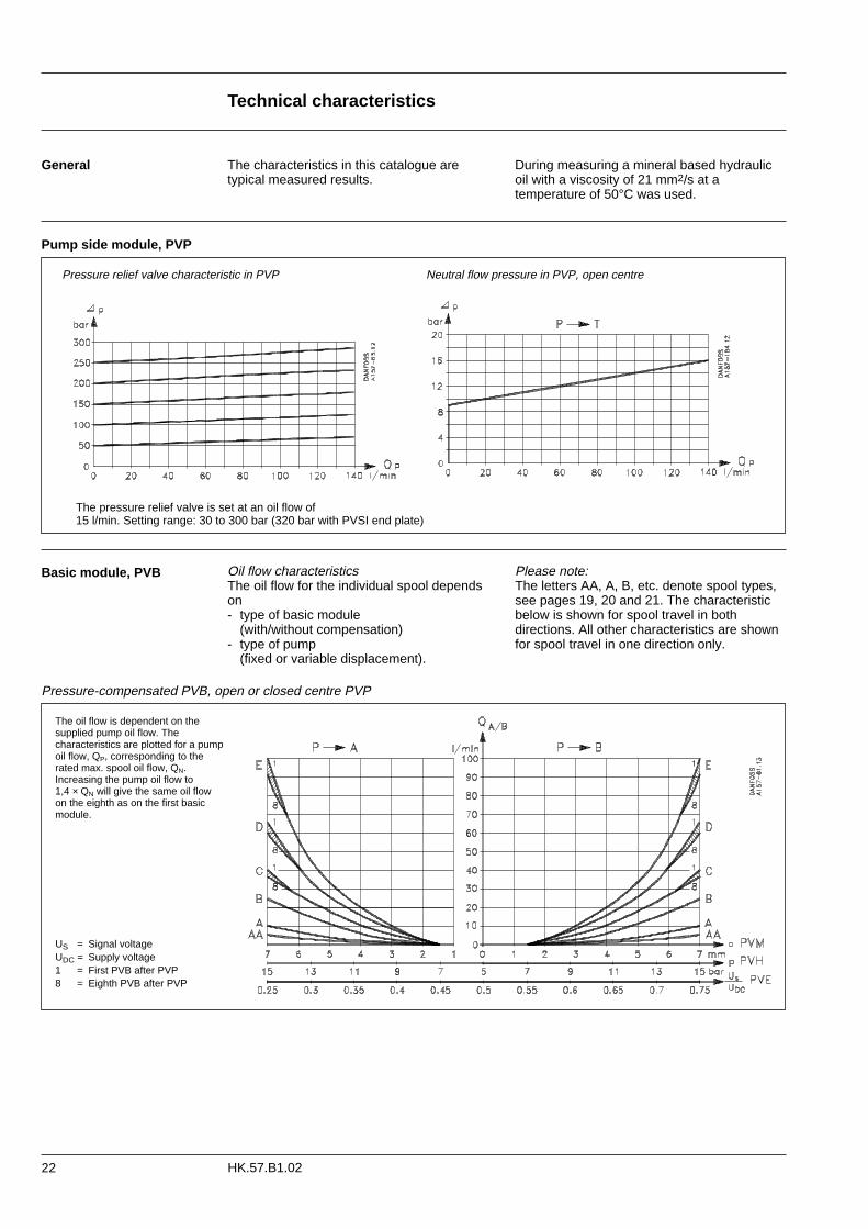
Pressure relief valve characteristic in PVP Neutral flow pressure in PVP, open centre
Pump side module, PVP
The pressure relief valve is set at an oil flow of 15 l/min. Setting range: 30 to 300 bar (320 bar with PVSI end plate)
Basic module, PVB
Pressure-compensated PVB, open or closed centre PVP
The oil flow is dependent on the supplied pump oil flow. The characteristics are plotted for a pumpoil flow, QP, corresponding to therated max. spool oil flow, QN. Increasing the pump oil flow to 1,4 × QN will give the same oil flow on the eighth as on the first basic module.
Oil flow characteristicsThe oil flow for the individual spool dependson- type of basic module
(with/without compensation)- type of pump
(fixed or variable displacement).
Please note:The letters AA, A, B, etc. denote spool types,see pages 19, 20 and 21. The characteristic below is shown for spool travel in both directions. All other characteristics are shownfor spool travel in one direction only.
During measuring a mineral based hydraulicoil with a viscosity of 21 mm2/s at a temperature of 50°C was used.
The characteristics in this catalogue are typical measured results.
General
US = Signal voltageUDC = Supply voltage 1 = First PVB after PVP8 = Eighth PVB after PVP

Technical characteristics
23HK.57.B1.02
The pressure drop of any oil flowing back to tank (QP - QA/B)is read on the curve for neutral flow pressure in PVP, page 22.
PVB
PVB without pressure compensation, open centre PVP
Oil flow as a function of spool travel Oil flow QA/B as a function of supplied pump oil flow (QP) - curves for fully displaced flow control spools.
PVB without pressure compensation, closed centre PVP
Set pressure difference between pump pressure and LS signal = 20 bar
The spool flow is dependent on the supplied oil flow, QP. The characteristics apply to supply oil flow of 130 l/min with the actu-ation of one basic module. If several basic modules are activatedat the same time, the characteristic depends on the load pressu-re of the actuated basic modules.
The oil flow is dependent on the pressure difference between the pump pressure and the LS signal. Normally the pressure difference isset at the LS pump regulator.
Set pressure difference between pump pressure and LS signal = 10 bar
Technical characteristics
24 HK.57.B1.02
PVB, PVL
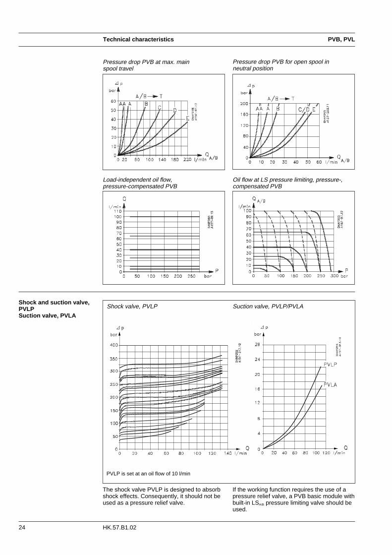
Pressure drop PVB at max. main spool travel
Suction valve, PVLP/PVLA
The shock valve PVLP is designed to absorbshock effects. Consequently, it should not beused as a pressure relief valve.
Shock and suction valve,PVLP Suction valve, PVLA
Pressure drop PVB for open spool in neutral position
PVLP is set at an oil flow of 10 l/min
Load-independent oil flow,pressure-compensated PVB
Oil flow at LS pressure limiting, pressure-,compensated PVB
If the working function requires the use of apressure relief valve, a PVB basic module withbuilt-in LSA/B pressure limiting valve should beused.
Shock valve, PVLP
Technical characteristics
25HK.57.B1.02
PVBS
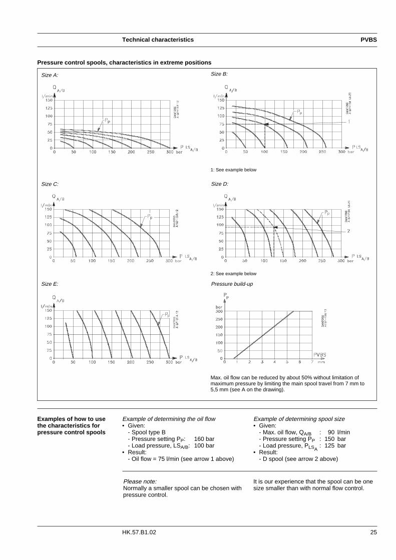
Pressure control spools, characteristics in extreme positions
Size A: Size B:
Size C: Size D:
Size E: Pressure build-up
Examples of how to usethe characteristics forpressure control spools
2: See example below
1: See example below
Max. oil flow can be reduced by about 50% without limitation of maximum pressure by limiting the main spool travel from 7 mm to 5,5 mm (see A on the drawing).
Example of determining the oil flow• Given:
- Spool type B- Pressure setting PP: 160 bar- Load pressure, LSA/B: 100 bar
• Result:- Oil flow = 75 l/min (see arrow 1 above)
Example of determining spool size• Given:
- Max. oil flow, QA/B : 90 l/min- Pressure setting PP : 150 bar- Load pressure, PLSA
: 125 bar• Result:
- D spool (see arrow 2 above)
It is our experience that the spool can be onesize smaller than with normal flow control.
Please note:Normally a smaller spool can be chosen withpressure control.

Technical characteristics
26 HK.57.B1.02
PVBS
Characteristics for floatposition main spools
Characteristics; oil flow, spool travel and voltage
The spools have 4,8 mm spooltravel in direction A and 8 mmtravel in direction B:• 4,8 mm spool displacement in
direction A gives max. oil flow to port A
• 4,8 mm spool displacement in direction B gives max. oil flow to port B
• 8 mm spool displacement in direction B gives completely open float position A/B→T.
Pressure drop A/B→T at max. spool travelwithin the proportional range (4,8 mm)
Spools D and E have the same opening areafor forward flow and return flow. Spool E cangive 100 l/min pressure compensated oil flowdue to a higher pressure drop across spool E.This occurs during spool actuation only.
Pressure drop A/B →T in float position
27
Dimensions
HK.57.B1.02
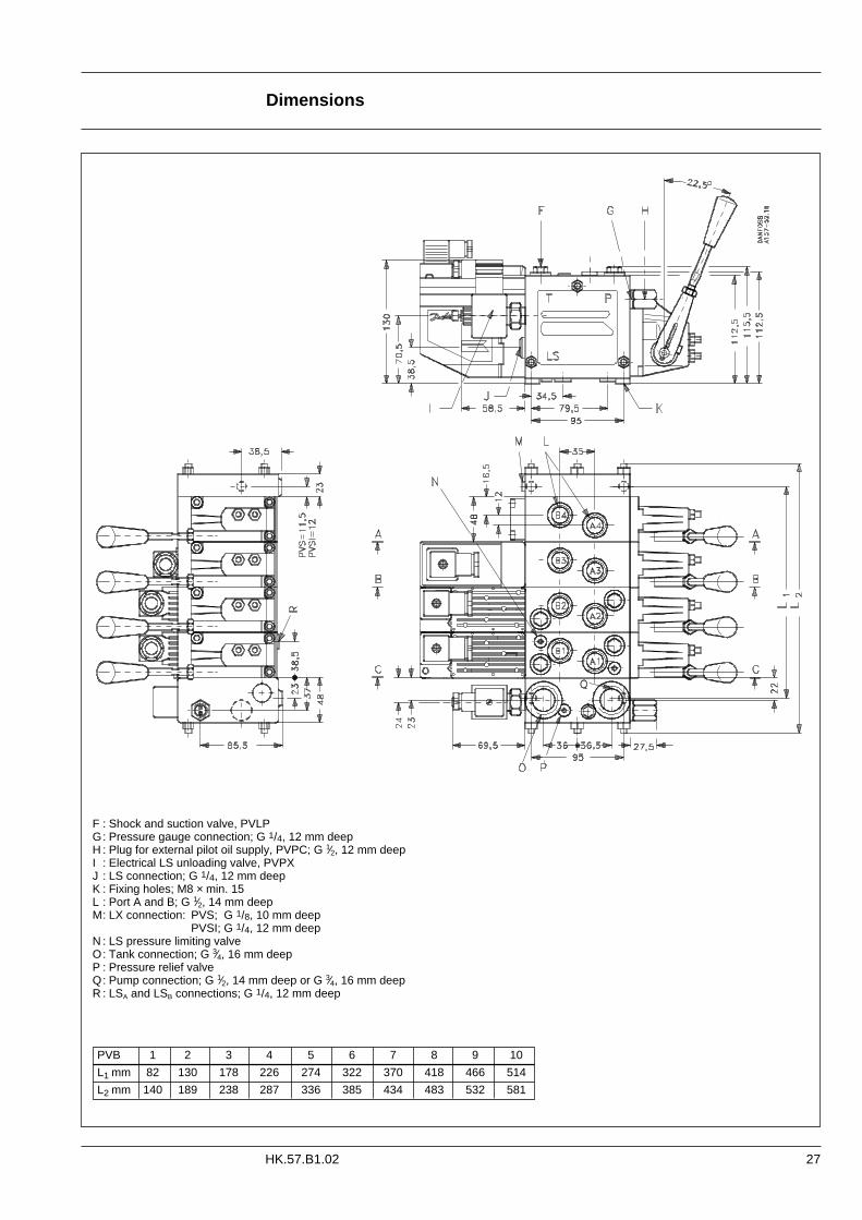
PVB 1 2 3 4 5 6 7 8 9 10
L1 mm 82 130 178 226 274 322 370 418 466 514
L2 mm 140 189 238 287 336 385 434 483 532 581
F : Shock and suction valve, PVLPG: Pressure gauge connection; G 1/4, 12 mm deepH : Plug for external pilot oil supply, PVPC; G 1⁄2, 12 mm deepI : Electrical LS unloading valve, PVPXJ : LS connection; G 1/4, 12 mm deepK : Fixing holes; M8 × min. 15L : Port A and B; G 1⁄2, 14 mm deepM: LX connection: PVS; G 1/8, 10 mm deep
PVSI; G 1/4, 12 mm deepN : LS pressure limiting valveO: Tank connection; G 3⁄4, 16 mm deepP : Pressure relief valveQ: Pump connection; G 1⁄2, 14 mm deep or G 3⁄4, 16 mm deepR : LSA and LSB connections; G 1/4, 12 mm deep

Dimensions
28 HK.57.B1.02
Control lever positions
F: G 1/4, 12 mm deep
Base with an angle of 22.5°
Base with an angle of 37.5°

29
Hydraulic systems
HK.57.B1.02
Manually actuated PVG 32 - fixed displacement pump
C: Over-centre valve
Electrically actuated PVG 32 - variable displacement pump (electrical actuator, shock valves, etc.)

Electrical systems
30 HK.57.B1.02
Electrical connections,general
Electrical connectionexample
The electrical connections to remote controllevers, PVE actuators and voltage supply aremade using an ordinary terminal strip.The wiring diagrams below and on page 31 to33 show only the basic outlines for the electri-cal connection.
Signal leadsSupply leads
F: Signal output, fault monitoring
E: Emergency stop
Signal leads must not act assupply leads at the same timeunless the distance between theactuator module PVE and termi-nal board is less than 3 m andthe lead cross-section is min.0,75 mm2.
Voltage supplyFor a mains transformer with stabilised outputvoltage, the ripple must not exceed 5% ofrated voltage.

31
System safety
HK.57.B1.02
1.Maximum safety demands
Building in safety and uncontrolled or blocked movements.To determine the degree of protection thatought to be built into the system, Danfossmakes the following distinctions.
1. Maximum safety demands2. High safety demands3. Average safety demands4. Limited safety demands.
Thus all functions are without operating pressure, i.e. locked in position, because thereis no pilot pressure on the pilot operatedcheck valve (C).
Actuation of the emergency switch (E) cuts offcurrent to the proportional valve and thesolenoid valve (M). Actuation in this case ismanual, but the result is the same as above.
Stopping or disconnecting the pump drivemotor is another safety measure, if the systemreaction time can be accepted.
Note:The neutral position switch in the remote control units should not be used.
PVEH with fault monitoring must have a constant voltage supply.
When the fault monitoring system in PVEH isconnected, the reaction to electrical andmechanical faults (e.g. a spool seizure) is fastand operator-independent. See page 11 “fault monitoring”.
A system can be protected against many electrical, hydraulic and mechanical faults bybuilding in components as shown in the diagram:R: Alarm logic EHA (or relay) connected to the
fault monitoring system in PVEHE: Electrical emergency stopM: Solenoid valveC: Pilot-operated check valve
The alarm logic EHA cuts off current to thesolenoid valve (M) when PVEH monitoringregisters a fault. The solenoid valve then leadsthe oil flow direct from pump to tank.
All makes and all types of directional controlvalves (incl. proportional valves) can fail. Thusthe necessary protection against the seriousconsequences of function failure shouldalways be built in.
For each application an assessment should bemade of the consequences of pressure failure

System safety
32 HK.57.B1.02
2. High safety demands
The difference between this safety methodand the one previously described (1) is thathere there is no built-in automatic fault monitoring and a neutral position switch (N) isconnected.
The method still gives a high degree of protection, but requires operator intervention.It is recommended that the neutral positionswitch be always connected to the electricalsystem. This then automatically cuts off current to the proportional valve when theremote control unit is in neutral position.

System safety
33HK.57.B1.02
3.Average safety demands
all functions requiring a higher operating pres-sure will not operate, see page 7.
The method can also be used in LS systemswith a variable displacement pump and closedcentre version proportional valve.The pressure after LS relief then depends onthe pump stand-by pressure.
no protection against hydraulic and mechanical faults (spool seizure in an extremeposition).
The difference from the previous method isthat the LS- signal from the proportional valveis led direct to tank when the emergency switch (E) is actuated. This can be achievedby using the Danfoss LS unloading valvePVPX, integrated in the pump side module.
In a system with open centre PVP and a fixeddisplacement pump, the effect of the PVPX isan almost pressureless system, 8-14 bar i.e.
The safety system can consist of an emergency switch (E) and a neutral positionswitch (N) if protection against electricalfailure is the only requirement. Here, there is
4.Limited safety demands

Other operating conditions
34 HK.57.B1.02
In our experience a degree of contaminationof 19/16 can be maintained by using a filterfineness as described in the next section.
Filtration
Oil The main duty of the oil in a hydraulic systemis to transfer energy; but it must also lubricatethe moving parts in hydraulic components,protect them against corrosion, and transportdirt particles and heat out of the system.It is therefore important to choose the correctoil with the correct additives. This gives normal operation and long working life.
Mineral oilFor systems with PVG 32 valves Danfossrecommends the use of mineral-basedhydraulic oil containing additives:Type HLP (DIN 51524) or HM (ISO 6743/4).
Non-flammable fluidsPhosphate-esters (HFDR fluids) can be usedwithout special precautions. However, dynamic seals must be replaced with FPM(Viton) seals. So please contact the SalesOrganization for Danfoss Hydraulics if the PVG 32 valve is to be used with phosphate-esters.
The following fluids should only be usedaccording to agreement with the Sales Organization for Danfoss Hydraulics:• Water-glycol mixtures (HFC fluids)• Water-oil emulsions (HFB fluids)• Oil-water emulsions (HFAE fluids)
Biodegradable oilsDanfoss PVG 32 valves can be used insystems with rapeseed oil. The use of rapeseed oil is conditioned by- complying with the demands on viscosity,
water content, temperature and filtering etc. (see chapters below and technical data
page 8).- adapting the operating conditions to the
directions of the oil supplier.
Before using other biodegradable fluids, please consult the Danfoss Sales Organization for Hydraulics.
Oil filtration must prevent particle content fromexceeding an acceptable level, i.e. an acceptable degree of contamination. Maximum contamination for Danfoss PVG 32is 19/16 (see ISO 4406. Calibration in accordance with the ACFTD method).
Particle content, degree of contamination
Effective filtration is the most important precondition in ensuring that a hydraulicsystem performs reliably and has a long working life. Filter manufacturers issue instructions and recommendations. It is advisable to follow them.
System filtersWhere demands on safety and reliability arevery high a pressure filter with bypass andindicator is recommended. Experience showsthat a 10 µm nominal filter (or finer) or a 20 µm absolute filter (or finer) is suitable.It is our experience that a return filter isadequate in a purely mechanically operatedvalve system.
The fineness of a pressure filter must be selected as described by the filter manufactu-rer so that a particle level of 19/16 is not exceeded.
The filter must be fitted with pressure gauge ordirt indicator to make it possible to check thecondition of the filter.
In systems with differential cylinders or accumulators the return filter must be sized tosuit the max. return oil flow. Pressure filtersmust be fitted to suit max. pump oil flow.
Internal filtersThe filters built into PVG 32 are not intendedto filter the system but to protect importantcomponents against large particles. Such particles can appear in the system as a resultof pump damage, hose fracture, use of quick-couplings, filter damage, starting up,contamination, etc.
The filter in the electrical actuator PVE protecting the solenoid valves has a mesh of150 µm.
Bursting pressure drop for internal filters is 25 bar.
Module selection chart
35HK.57.B1.02
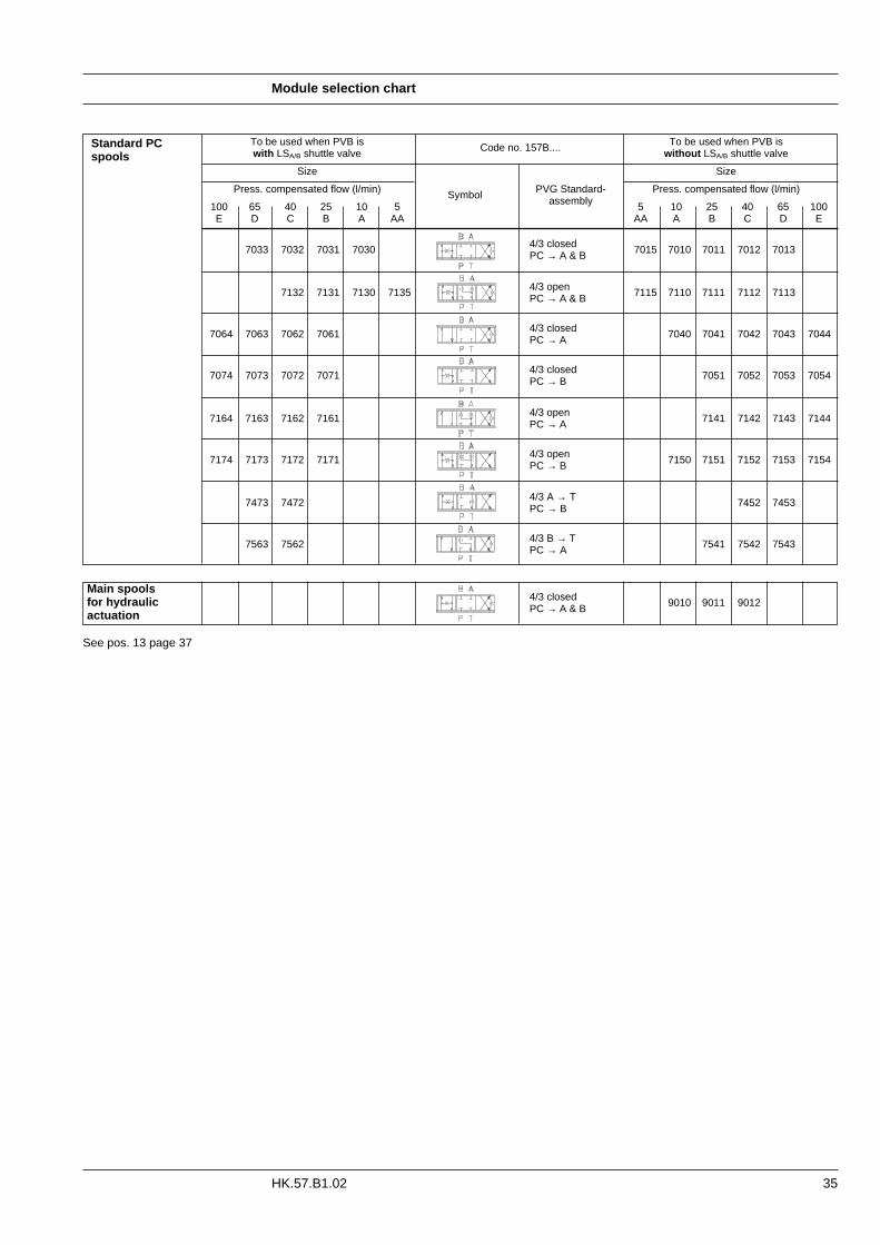
To be used when PVB is To be used when PVB iswith LSA/B shuttle valve Code no. 157B.... without LSA/B shuttle valve
Size Size
Press. compensated flow (l/min) Symbol PVG Standard- Press. compensated flow (l/min)
100 65 40 25 10 5 assembly 5 10 25 40 65 100E D C B A AA AA A B C D E
4/3 closed7033 7032 7031 7030 PC → A & B 7015 7010 7011 7012 7013
7132 7131 7130 4/3 open7135 PC → A & B 7115 7110 7111 7112 7113
4/3 closed 70407064 7063 7062 7061 PC → A 7041 7042 7043 7044
4/3 closed7074 7073 7072 7071 PC → B 7051 7052 7053 7054
4/3 open7164 7163 7162 7161 PC → A 7141 7142 7143 7144
4/3 open7174 7173 7172 7171 PC → B 7150 7151 7152 7153 7154
4/3 A → T 7452 74537473 7472 PC → B
4/3 B → T7563 7562 PC → A 7541 7542 7543
4/3 closed 9010 9011 9012PC → A & B
Standard PCspools
Main spools for hydraulicactuation
See pos. 13 page 37
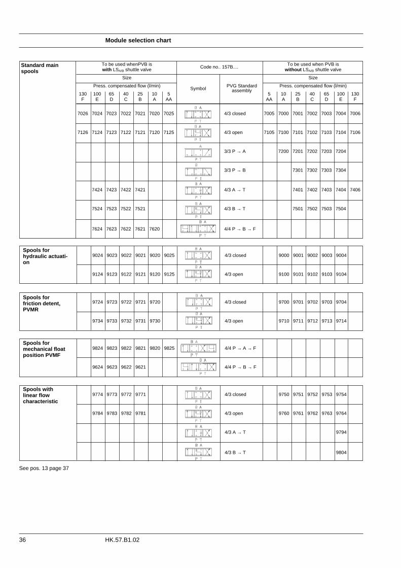
Module selection chart
36 HK.57.B1.02
To be used whenPVB is To be used when PVB iswith LSA/B shuttle valve Code no.. 157B.... without LSA/B shuttle valve
Size Size
Press. compensated flow (l/min) Press. compensated flow (l/min)
130 100 65 40 25 10 5Symbol PVG Standard
5 10 25 40 65 100 130F E D C B A AA
assembly
AA A B C D E F
7026 7024 7023 7022 7021 7020 7025 4/3 closed 7005 7000 7001 7002 7003 7004 7006
7126 7124 7123 7122 7121 7120 7125 4/3 open 7105 7100 7101 7102 7103 7104 7106
3/3 P → A 7200 7201 7202 7203 7204
3/3 P → B 7301 7302 7303 7304
7424 7423 7422 7421 4/3 A → T 7401 7402 7403 7404 7406
7524 7523 7522 7521 4/3 B → T 7501 7502 7503 7504
7624 7623 7622 7621 7620 4/4 P → B → F
9724 9723 9722 9721 9720 4/3 closed 9700 9701 9702 9703 9704
9734 9733 9732 9731 9730 4/3 open 9710 9711 9712 9713 9714
9774 9773 9772 9771 4/3 closed 9750 9751 9752 9753 9754
9784 9783 9782 9781 4/3 open 9760 9761 9762 9763 9764
4/3 A → T 9794
4/3 B → T 9804
9024 9023 9022 9021 9020 9025 4/3 closed 9000 9001 9002 9003 9004
9124 9123 9122 9121 9120 9125 4/3 open 9100 9101 9102 9103 9104
Standard mainspools
Spools forhydraulic actuati-on
Spools for friction detent,PVMR
Spools formechanical floatposition PVMF
Spools with linear flow characteristic
See pos. 13 page 37
9824 9823 9822 9821 9820 9825 4/4 P → A → F
9624 9623 9622 9621 4/4 P → B → F
Module selection chart
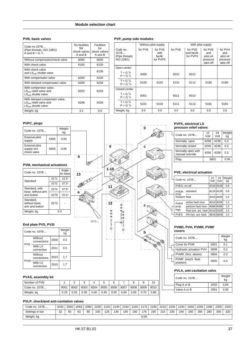
37HK.57.B1.02
WeightCode no. 157B.... kg
Cover for PVM 0001 0.1
Hydraulic actuation PVH 0008 0.2
PVMR, (frict. detent) 0004 0.3
PVMF, (mech. float position) 0005 0.3
Code no. 157B....12 24 Weight
Volt Volt kg
PVEO, on-off 4216 4228 0.6
PVEM standard 4116 4128 0.9prop.medium float 4416 4428 1.0
PVEH active fault mon. 4016 4028 1.0
prop. passive fault mon. 4086 4088 1.0high float pos. act. fault. 4316 4328 1.0
PVES 0% hys. act. fault. 4816 4828 1.0
Without pilot supply With pilot supply
Code no. for PVE for PVE for PVE for PVE for PVE for PVH157B.... with and facilit. and and(Pipe threads facilit. for PVPX pilot oil pilot oilISO 228/1) for PVPX pressure pressure
take-off take-off
Open center
T = G 3/4P = G 1/2 5000 5010 5012
T = G 3/4P = G 3/4 5100 5102 5110 5112 5180 5190
Closed center
T = G 3/4P = G 1/2 5001 5011 5013
T = G 3/4P = G 3/4 5101 5103 5111 5113 5181 5191
Weight, kg 3.0 3.0 3.0 3.0 3.0 3.0
WeightCode no. 157B.... kg
Without
PVSconnections 2000 0.5
With LXconnection 2011 0.5
Without2014 1.7
PVSIconnections
With LXconnection 2015 1.7
PVE, electrical actuation
PVB, basic valves
Code no.157B.... No facilities Facilities
(Pipe threads, ISO 228/1) for for
A and B = G 1/2 shock valves shock valvesA and B A and B
Without compensator/check valve 6000 6030
With check valve 6100 6130
With check valveand LSA/B shuttle valve 6136
With compensator valve 6200 6230
With damped compensator valve 6206 6236
With compenstor valve,LSA/B relief valve and 6203 6233LSA/B shuttle valve
With damped compenstor valve,LSA/B relief valve and 6208 6238LSA/B shuttle valve
Weight, kg 3.1 3.0
PVPC, plugs
WeightCode no. 157B.... kg
External pilot 5400 0.05supply
External pilotsupply incl. 5600 0.05check valve
PVM, mechanical actuations
PVP, pump side modules
Code no. 157B....12 24 Weight
Volt Volt kg
Normally open 4236 4238 0.3
Normally closed 4246 4248 0.3
Normally open withmanual override 4256 4258 0.3
Plug 5601 0.06
PVPX, electrical LS pressure relief valves
PVAS, assembly kit
Number of PVB 1 2 3 4 5 6 7 8 9 10
Code no. 157B.... 8001 8002 8003 8004 8005 8006 8007 8008 8009 8010
Weight, kg 0.15 0.25 0.30 0.40 0.45 0.50 0.60 0.65 0.70 0.80
Code no. 157B....Angle
on base
Standard3171 22.5°
3172 37.5°
Standard, with 3174 37.5°base, without arm and button 3175 22.5°
Standard, without base, 3173 -arm and button
Weight, kg 0.4
End plate PVS, PVSI
0
0
13
a
0
c
1-10
11
12
b
c
PVMD, PVH, PVMR, PVMFcovers
PVLA, anti-cavitation valve
WeightCode no. 157B.... kg
Plug A or B 2002 0.04
Valve A or B 2001 0.05
Code no. 157B.... 2032 2050 2063 2080 2100 2125 2140 2150 2160 2175 2190 2210 2230 2240 2250 2265 2280 2300 2320
Settings in bar 32 50 63 80 100 125 140 150 160 175 190 210 230 240 250 265 280 300 320
Weight, kg 0,05
PVLP, shock/and anti-cavitation valves

Order specification
38 HK.57.B1.02
Max. pressure setting of LSA and LSB valves relative to PVLP shock valve
Order specification An order form for Danfoss PVG 32 hydraulicvalve is shown on the next page. The formcan be obtained from the Danfoss HydraulicsSales Organization.
Both the module selection chart on the previ-ous pages and the order form are divided intofields 0, 1-10, 11, 12, 13, a, b, and c.
Each module has its own field:0: - Pump side module PVP
- Plug for external pilot oil supply PVPC- Electrical LS unloading valve PVPX
1-10: Basic valves PVB13: Main spool PVBS a: Mechanical actuator PVMc: - Cover for mechanical actuation PVMD
- Cover for hydraulic actuation PVH - Electrical actuators PVE
b: - Shock and suction valve PVLP - Suction valve PVLA
11: End plate PVS 12: Assembly kit PVAS
Please state- Code numbers of all modules required- Required setting (P) for pump side module- Required setting of LSA/B pressure limiting
valves, see pressure setting guidance below.
Standard and option assemblyThe PVG 32 valve group is assembled theway the module selection chart shows if thecode number for PVM is written in field a, andthe code number for PVMD, PVE or PVH infield c.
The valve group is assembled so that themechanical actuator is mounted on the oppo-site end of the basic module, if the code num-ber for PVM is written in field c of the orderform and the code numbers for PVMD, PVE orPVH in field a.
ReorderingThe space at the top right-hand corner of theform is for Danfoss to fill in. The code numberfor the whole of the specified valve group(PVG No.) is entered here.
In the event of a repeat order all you have todo is enter the number Danfoss has given onthe initial confirmation of order.
Pressure setting limitsThe maximum setting pressure for the pressu-re limiting valves LSA or LSB depends on thechosen pressure setting for shock valvePVLP.
The maximum values recommended to avoidinteraction can be read in the following table.
The figures in the table have been calculatedaccording to the following expressions:- PVLP ≤150 bar: LSA/B ≤ 0,8 × PPVLP- PVLP >150 bar: PPVLP - LSA/B ≥ 30 bar.
Setting pressure for PVLP (bar) 32 50 63 80 100 125 140 150 160 175 190 210 230 240 250 280 300 320
Max. setting pressure for LSA/B (bar) 40 50 64 80 100 112 120 130 145 160 180 200 210 220 250 270 290
Min. setting pressure for LSA/B (bar) 30

39HK.57.B1.02
0 157B 157BFunction A-Port
p = bar 157B
B-Port
a 157B 1 157B 157B 13 157B c
b 157B LSA bar LSB bar 157B b
a 157B 2 157B 157B 13 157B c
b 157B LSA bar LSB bar 157B b
a 157B 3 157B 157B 13 157B c
b 157B LSA bar LSB bar 157B b
a 157B 4 157B 157B 13 157B c
b 157B LSA bar LSB bar 157B b
a 157B 5 157B 157B 13 157B c
b 157B LSA bar LSB bar 157B b
a 157B 6 157B 157B 13 157B c
b 157B LSA bar LSB bar 157B b
a 157B 7 157B 157B 13 157B c
b 157B LSA bar LSB bar 157B b
a 157B 8 157B 157B 13 157B c
b 157B LSA bar LSB bar 157B b
a 157B 9 157B 157B 13 157B c
b 157B LSA bar LSB bar 157B b
a 157B 10 157B 157B 13 157B c
b 157B LSA bar LSB bar 157B b
11 157B
12 157B
Filled in by Date
Proportional Valve PVG 32PVG No.
Specification Subsidiary/Dealer
Customer Application
Note: Separate specification pads with 50 sheets available under the literature no HZ.57.A3.52
40
Danfoss can accept no responsibility for possible errors in catalogues, brochures and other printed material. Danfoss reserves the right to alter its products without notice. This also applies toproducts already on order provided that such alterations can be made without subsequential changes being necessary in specifications already agreed.All trademarks in this material are property of the respective companies. Danfoss and the Danfoss logotype are trademarks of Danfoss A/S. All rights reserved.
DK-6430 NordborgDenmark
HK.57.B1.02 © Danfoss 12/98
Danfoss hydraulics
ISO 9001
ISO9001
Danfoss Mobile Hydraulics have been manufacturedto meet the quality demands specified by ISO 9001.
INTERNATIONAL STANDARDINTERNATIONAL ORGANIZATION FOR STANDARDIZATION
ORGANISATION INTERNATIONALE DE NORMALISATION
Quality management and quality assurance standards
Please contact the Danfoss Sales Organization for Hydraulics for further information
• Remote control units• Electronics for hydr. components • Gear wheel motors• Gear wheel pumps• Cartridge valves• Directional control valves
Catalogues and leaflets are available for detailed information on the following hydraulic components:
• Low speed high torque hydraulic motors• Hydrostatic steering units• Steering columns• Valve blocks• Flow-amplifiers• Priority valves• Torque amplifiers• Proportional valves
Conversion factors 1 daNm = 88.51 lbf in1 daN = 2.248 lbf1 bar = 14.50 lbf/in2
1 mm = 0.0394 in
1 cm3 = 0.061 in3
1 l = 0.22 gallon, UK1 l = 0.264 gallon, US°F = 1.8 × °C + 32