Embed Size (px)
Citation preview
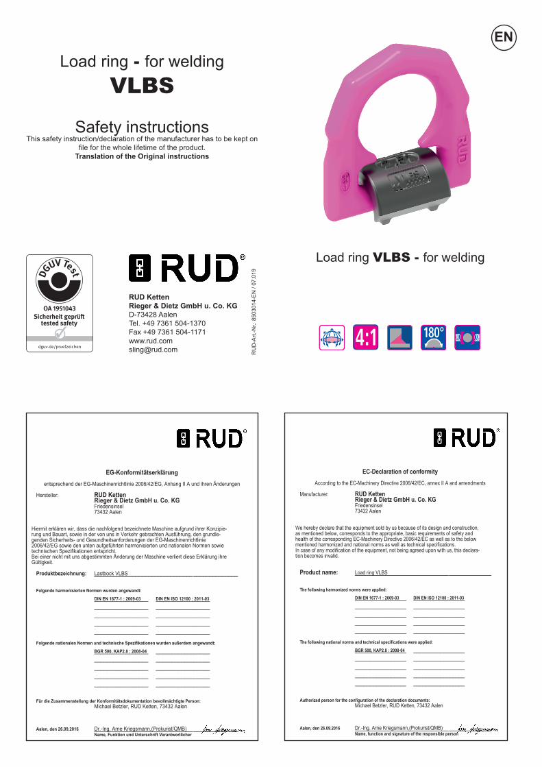
Load ring VLBS - for welding
RUD Ketten Rieger & Dietz GmbH u. Co. KGD-73428 AalenTel. +49 7361 504-1370Fax +49 7361 [email protected] R
UD
-Art.
-Nr.:
850
3014
-EN
/ 07
.019
Load ring - for welding
VLBS
Safety instructions This safety instruction/declaration of the manufacturer has to be kept on
file for the whole lifetime of the product. Translation of the Original instructions
EN
EC-Declaration of conformityAccording to the EC-Machinery Directive 2006/42/EC, annex II A and amendments
Manufacturer: RUD KettenRieger & Dietz GmbH u. Co. KGFriedensinsel73432 Aalen
We hereby declare that the equipment sold by us because of its design and construction,as mentioned below, corresponds to the appropriate, basic requirements of safety andhealth of the corresponding EC-Machinery Directive 2006/42/EC as well as to the belowmentioned harmonized and national norms as well as technical specifications.In case of any modification of the equipment, not being agreed upon with us, this declara-tion becomes invalid.
Product name: Load ring VLBS__________________________________________________________________________________________
The following harmonized norms were applied:DIN EN 1677-1 : 2009-03 DIN EN ISO 12100 : 2011-03_________________ __________________________________ __________________________________ __________________________________ __________________________________ _________________
The following national norms and technical specifications were applied:BGR 500, KAP2.8 : 2008-04_________________ __________________________________ __________________________________ __________________________________ __________________________________ _________________
Authorized person for the configuration of the declaration documents:Michael Betzler, RUD Ketten, 73432 Aalen
Aalen, den 26.09.2016 Dr.-Ing. Arne Kriegsmann,(Prokurist/QMB)_____________________________________________Name, function and signature of the responsible person
EG-Konformitätserklärungentsprechend der EG-Maschinenrichtlinie 2006/42/EG, Anhang II A und ihren Änderungen
Hersteller: RUD KettenRieger & Dietz GmbH u. Co. KGFriedensinsel73432 Aalen
Hiermit erklären wir, dass die nachfolgend bezeichnete Maschine aufgrund ihrer Konzipie-rung und Bauart, sowie in der von uns in Verkehr gebrachten Ausführung, den grundle-genden Sicherheits- und Gesundheitsanforderungen der EG-Maschinenrichtlinie2006/42/EG sowie den unten aufgeführten harmonisierten und nationalen Normen sowietechnischen Spezifikationen entspricht.Bei einer nicht mit uns abgestimmten Änderung der Maschine verliert diese Erklärung ihreGültigkeit.
Produktbezeichnung: Lastbock VLBS__________________________________________________________________________________________
Folgende harmonisierten Normen wurden angewandt:DIN EN 1677-1 : 2009-03 DIN EN ISO 12100 : 2011-03_________________ __________________________________ __________________________________ __________________________________ __________________________________ _________________
Folgende nationalen Normen und technische Spezifikationen wurden außerdem angewandt:BGR 500, KAP2.8 : 2008-04_________________ __________________________________ __________________________________ __________________________________ __________________________________ _________________
Für die Zusammenstellung der Konformitätsdokumentation bevollmächtigte Person:Michael Betzler, RUD Ketten, 73432 Aalen
Aalen, den 26.09.2016 Dr.-Ing. Arne Kriegsmann,(Prokurist/QMB)_____________________________________________Name, Funktion und Unterschrift Verantwortlicher
180°4:1
The evidence of the suitability of the used weld metal must be mentioned by the respective filler material manufacturer.8. The places where the lifting points are fixed should be marked with colour. 9. At outdoor sites or in case of special danger of corrosion, the welds should only be designed as continuous, fillet welds. The HV weld at the VLBS guarantees a connection via the whole cross section of the material. This corresponds to a closed weld showing no signs of corrosion.10. The distance lugs assist in achieving the correct root weld (approx. 3 mm = 0.1 inch). They may not be removed.11. RUD-Lifting points must not be used under chemical influences such as acids, alkaline solutions and vapours e.g. in pickling baths or hot dip galvanising plants. 12. If the lifting points are used exclusively for lashing the value of the working load limit can be doubled. LC = 2 x WLL13. After welding, an annual inspection or sooner if conditions dic-tate should be undertaken by a competent person examining the continued suitability. Also after damage and special occurrences.Inspection criteria concerning paragraphs 2 and 13:
z The lifting point should be complete. z The working load limit and manufacturers stamp should be
clearly visible. z Deformation of the component parts such as body and
load ring. z Mechanical damage, such as notches, particulary in high
stress areas. z Wear should be no more than 10 % of cross sectional
diameter. z Evidence of corrosion. z Cracks or other damages to the welding.
A non-adherence to this advice may result damages of per-sons and materials!
The welding should only be carried out according to DIN EN ISO 9606-1 or AWS Standards by an authorized welder.Welding sequence:
z Start tacking in the center of the welding block. z Welding in stringer beads. z Before carrying out the top run, carefully clean the root. z The welding process must not be interrupted for such a
time that the welding block loses the welding temperature. z Attention: Do not weld at the pink powder coated, heat
treated load ring.
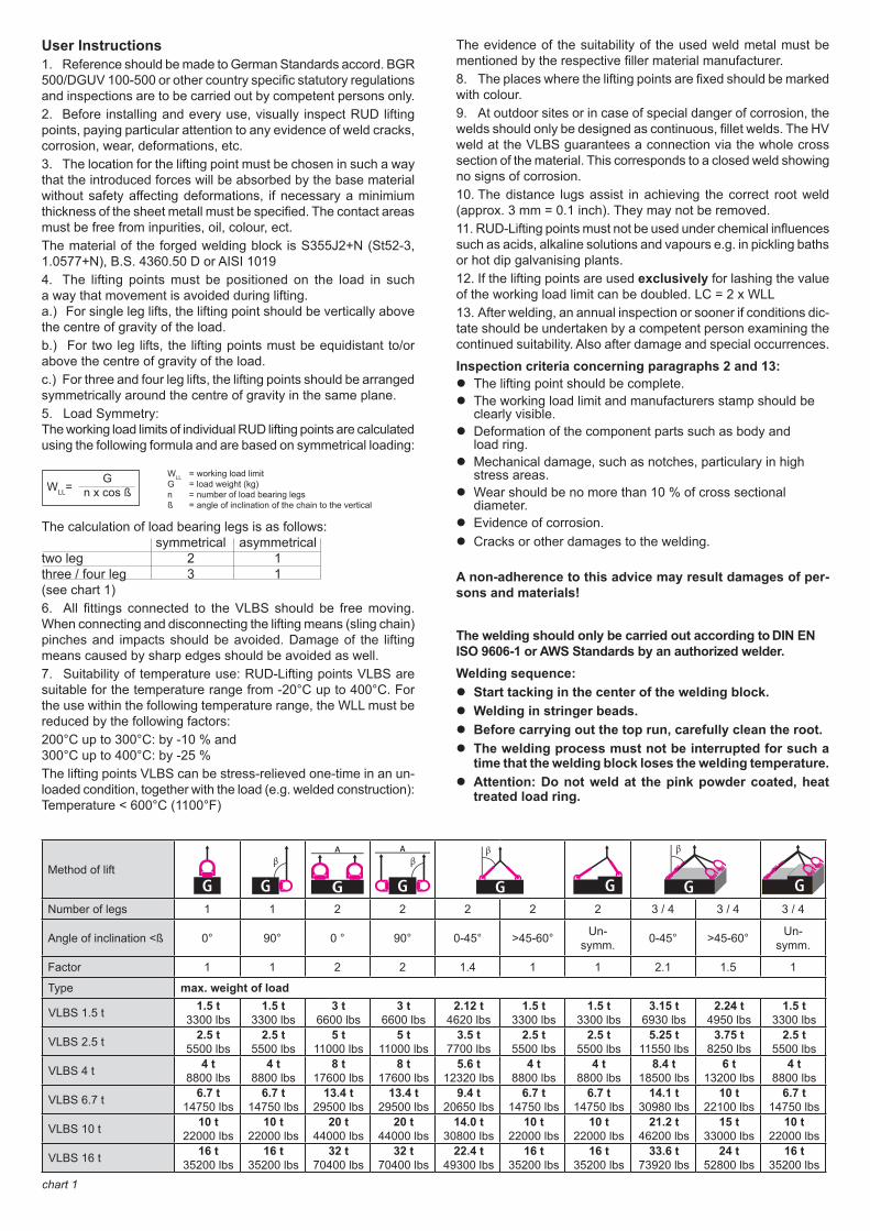
User Instructions1. Reference should be made to German Standards accord. BGR 500/DGUV 100-500 or other country specific statutory regulations and inspections are to be carried out by competent persons only.2. Before installing and every use, visually inspect RUD lifting points, paying particular attention to any evidence of weld cracks, corrosion, wear, deformations, etc. 3. The location for the lifting point must be chosen in such a way that the introduced forces will be absorbed by the base material without safety affecting deformations, if necessary a minimium thickness of the sheet metall must be specified. The contact areas must be free from inpurities, oil, colour, ect.The material of the forged welding block is S355J2+N (St52-3, 1.0577+N), B.S. 4360.50 D or AISI 10194. The lifting points must be positioned on the load in such a way that movement is avoided during lifting. a.) For single leg lifts, the lifting point should be vertically above the centre of gravity of the load.b.) For two leg lifts, the lifting points must be equidistant to/or above the centre of gravity of the load.c.) For three and four leg lifts, the lifting points should be arranged symmetrically around the centre of gravity in the same plane. 5. Load Symmetry: The working load limits of individual RUD lifting points are calculated using the following formula and are based on symmetrical loading:
The calculation of load bearing legs is as follows: symmetrical asymmetrical two leg 2 1 three / four leg 3 1 (see chart 1)6. All fittings connected to the VLBS should be free moving. When connecting and disconnecting the lifting means (sling chain) pinches and impacts should be avoided. Damage of the lifting means caused by sharp edges should be avoided as well.7. Suitability of temperature use: RUD-Lifting points VLBS are suitable for the temperature range from -20°C up to 400°C. For the use within the following temperature range, the WLL must be reduced by the following factors:200°C up to 300°C: by -10 % and 300°C up to 400°C: by -25 %The lifting points VLBS can be stress-relieved one-time in an un-loaded condition, together with the load (e.g. welded construction): Temperature < 600°C (1100°F)
Gn x cos ß
WLL = working load limitG = load weight (kg)n = number of load bearing legsß = angle of inclination of the chain to the vertical
WLL=
chart 1
Method of liftG G G G G G G G
Number of legs 1 1 2 2 2 2 2 3 / 4 3 / 4 3 / 4
Angle of inclination <ß 0° 90° 0 ° 90° 0-45° >45-60° Un- symm. 0-45° >45-60° Un-
symm.
Factor 1 1 2 2 1.4 1 1 2.1 1.5 1
Type max. weight of load
VLBS 1.5 t 1.5 t 3300 lbs
1.5 t 3300 lbs
3 t 6600 lbs
3 t 6600 lbs
2.12 t 4620 lbs
1.5 t 3300 lbs
1.5 t 3300 lbs
3.15 t 6930 lbs
2.24 t 4950 lbs
1.5 t 3300 lbs
VLBS 2.5 t 2.5 t 5500 lbs
2.5 t 5500 lbs
5 t 11000 lbs
5 t 11000 lbs
3.5 t 7700 lbs
2.5 t 5500 lbs
2.5 t 5500 lbs
5.25 t 11550 lbs
3.75 t 8250 lbs
2.5 t 5500 lbs
VLBS 4 t 4 t 8800 lbs
4 t 8800 lbs
8 t 17600 lbs
8 t 17600 lbs
5.6 t 12320 lbs
4 t 8800 lbs
4 t 8800 lbs
8.4 t 18500 lbs
6 t 13200 lbs
4 t 8800 lbs
VLBS 6.7 t 6.7 t 14750 lbs
6.7 t 14750 lbs
13.4 t 29500 lbs
13.4 t 29500 lbs
9.4 t 20650 lbs
6.7 t 14750 lbs
6.7 t 14750 lbs
14.1 t 30980 lbs
10 t 22100 lbs
6.7 t 14750 lbs
VLBS 10 t 10 t 22000 lbs
10 t 22000 lbs
20 t 44000 lbs
20 t 44000 lbs
14.0 t 30800 lbs
10 t 22000 lbs
10 t 22000 lbs
21.2 t 46200 lbs
15 t 33000 lbs
10 t 22000 lbs
VLBS 16 t 16 t 35200 lbs
16 t 35200 lbs
32 t 70400 lbs
32 t 70400 lbs
22.4 t 49300 lbs
16 t 35200 lbs
16 t 35200 lbs
33.6 t 73920 lbs
24 t 52800 lbs
16 t 35200 lbs
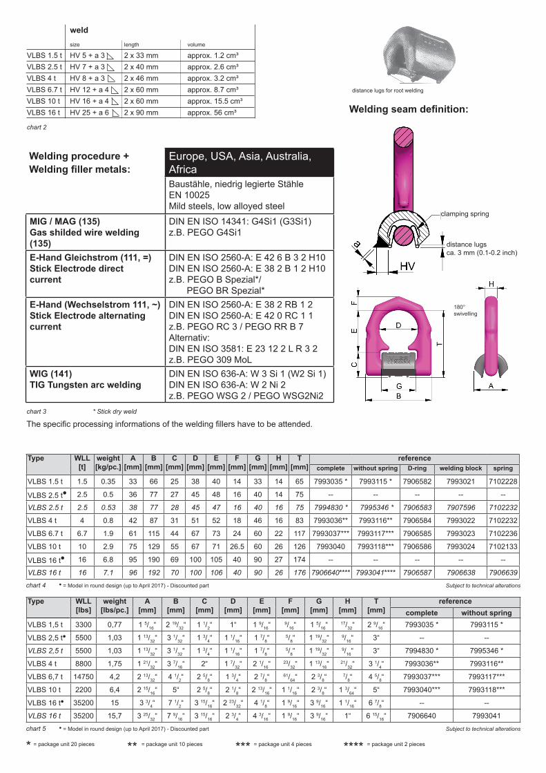
chart 2
Welding seam definition:
distance lugs for root welding
The specific processing informations of the welding fillers have to be attended.
Welding procedure + Welding filler metals:
chart 3 * Stick dry weld
Europe, USA, Asia, Australia, AfricaBaustähle, niedrig legierte Stähle EN 10025Mild steels, low alloyed steel
MIG / MAG (135)Gas shilded wire welding (135)
DIN EN ISO 14341: G4Si1 (G3Si1)z.B. PEGO G4Si1
E-Hand Gleichstrom (111, =) Stick Electrode direct current
DIN EN ISO 2560-A: E 42 6 B 3 2 H10 DIN EN ISO 2560-A: E 38 2 B 1 2 H10 z.B. PEGO B Spezial*/ PEGO BR Spezial*
E-Hand (Wechselstrom 111, ~) Stick Electrode alternating current
DIN EN ISO 2560-A: E 38 2 RB 1 2DIN EN ISO 2560-A: E 42 0 RC 1 1z.B. PEGO RC 3 / PEGO RR B 7Alternativ:DIN EN ISO 3581: E 23 12 2 L R 3 2 z.B. PEGO 309 MoL
WIG (141)TIG Tungsten arc welding
DIN EN ISO 636-A: W 3 Si 1 (W2 Si 1)DIN EN ISO 636-A: W 2 Ni 2z.B. PEGO WSG 2 / PEGO WSG2Ni2
weld size length volume
VLBS 1.5 t HV 5 + a 3 2 x 33 mm approx. 1.2 cm³VLBS 2.5 t HV 7 + a 3 2 x 40 mm approx. 2.6 cm³VLBS 4 t HV 8 + a 3 2 x 46 mm approx. 3.2 cm³VLBS 6.7 t HV 12 + a 4 2 x 60 mm approx. 8.7 cm³VLBS 10 t HV 16 + a 4 2 x 60 mm approx. 15.5 cm³VLBS 16 t HV 25 + a 6 2 x 90 mm approx. 56 cm³
distance lugsca. 3 mm (0.1-0.2 inch)
180° swivelling
clamping spring
Type WLL [t]
weight [kg/pc.]
A [mm]
B [mm]
C [mm]
D [mm]
E [mm]
F [mm]
G [mm]
H [mm]
T [mm]
referencecomplete without spring D-ring welding block spring
VLBS 1.5 t 1.5 0.35 33 66 25 38 40 14 33 14 65 7993035 * 7993115 * 7906582 7993021 7102228
VLBS 2.5 tz 2.5 0.5 36 77 27 45 48 16 40 14 75 -- -- -- -- --
VLBS 2.5 t 2.5 0.53 38 77 28 45 47 16 40 16 75 7994830 * 7995346 * 7906583 7907596 7102232
VLBS 4 t 4 0.8 42 87 31 51 52 18 46 16 83 7993036** 7993116** 7906584 7993022 7102232
VLBS 6.7 t 6.7 1.9 61 115 44 67 73 24 60 22 117 7993037*** 7993117*** 7906585 7993023 7102236
VLBS 10 t 10 2.9 75 129 55 67 71 26.5 60 26 126 7993040 7993118*** 7906586 7993024 7102133
VLBS 16 tz 16 6.8 95 190 69 100 105 40 90 27 174 -- -- -- -- --
VLBS 16 t 16 7.1 96 192 70 100 106 40 90 26 176 7906640**** 7993041**** 7906587 7906638 7906639
chart 4 z = Model in round design (up to April 2017) - Discounted part Subject to technical alterations
= package unit 20 pieces = package unit 10 pieces = package unit 4 pieces = package unit 2 pieces* ** *** ****
Type WLL [lbs]
weight [lbs/pc.]
A [mm]
B [mm]
C [mm]
D [mm]
E [mm]
F [mm]
G [mm]
H [mm]
T [mm]
referencecomplete without spring
VLBS 1,5 t 3300 0,77 1 5/16“ 2 19/32“ 1 1/2“ 1“ 1 9/16“ 9/16“ 1 5/16“ 17/32“ 2 9/16“ 7993035 * 7993115 *
VLBS 2,5 tz 5500 1,03 1 13/32“ 3 1/32“ 1 3/4“ 1 1/16“ 1 7/8“ 5/8“ 1 19/32“ 9/16“ 3“ -- --
VLBS 2,5 t 5500 1,03 1 13/32“ 3 1/32“ 1 3/4“ 1 1/16“ 1 7/8“ 5/8“ 1 19/32“ 9/16“ 3“ 7994830 * 7995346 *
VLBS 4 t 8800 1,75 1 21/32“ 3 7/16“ 2“ 1 7/32“ 2 1/16“ 23/32“ 1 13/16“ 21/32“ 3 1/4“ 7993036** 7993116**
VLBS 6,7 t 14750 4,2 2 13/32“ 4 1/2“ 2 5/8“ 1 3/4“ 2 7/8“ 61/64“ 2 3/8“ 7/8“ 4 5/8“ 7993037*** 7993117***
VLBS 10 t 2200 6,4 2 15/16“ 5“ 2 5/8“ 2 1/8“ 2 13/16“ 1 1/16“ 2 3/8“ 1 3/64“ 5“ 7993040*** 7993118***
VLBS 16 tz 35200 15 3 3/4“ 7 1/2“ 3 15/16“ 2 23/32“ 4 1/8“ 1 9/16“ 3 9/16“ 1 1/16“ 6 7/8“ -- --
VLBS 16 t 35200 15,7 3 25/32“ 7 9/16“ 3 15/16“ 2 3/4“ 4 3/16“ 1 9/16“ 3 9/16“ 1“ 6 15/16“ 7906640 7993041chart 5 z = Model in round design (up to April 2017) - Discounted part Subject to technical alterations