Embed Size (px)
Citation preview
1.01
a
Loader and Utilities Manual(including ADSP-BFxxx and ADSP-21xxx)
Revision 1.3, May 2014
Part Number
82-100114-01
Analog Devices, Inc.One Technology WayNorwood, Mass. 02062-9106
1.1

Copyright Information©2014 Analog Devices, Inc., ALL RIGHTS RESERVED. This document may not be reproduced in any formwithout prior, express written consent from Analog Devices, Inc. Printed in the USA.
Disclaimer
Analog Devices, Inc. reserves the right to change this product without prior notice. Information furnished byAnalog Devices is believed to be accurate and reliable. However, no responsibility is assumed by Analog Devicesfor its use; nor for any infringement of patents or other rights of third parties which may result from its use. Nolicense is granted by implication or otherwise under the patent rights of Analog Devices, Inc.
Trademark and Service Mark Notice
The Analog Devices logo, Blackfin, SHARC, EngineerZone, VisualDSP++, CrossCore Embedded Studio, EZ-KITLite, and EZ-Board are registered trademarks of Analog Devices, Inc.Blackfin+ is a trademark of Analog Devices, Inc.All other brand and product names are trademarks or service marks of their respective owners.
CrossCore Embedded Studio 1.1.0 Loader and Utilities ManualRevision 1.3, May 2014
2

Contents
Chapter 1: Preface...................................................................................................................9Purpose of This Manual......................................................................................................................................................................................9Intended Audience............................................................................................................................................................................................. 9Manual Contents.................................................................................................................................................................................................9What's New in This Manual.............................................................................................................................................................................. 10Technical Support.............................................................................................................................................................................................10Supported Processors...................................................................................................................................................................................... 11Product Information.........................................................................................................................................................................................11
Analog Devices Web Site...................................................................................................................................................................................................... 11EngineerZone........................................................................................................................................................................................................................ 12
Notation Conventions...................................................................................................................................................................................... 12
Chapter 2: Introduction .......................................................................................................15Definition of Terms........................................................................................................................................................................................... 15Program Development Flow............................................................................................................................................................................18
Compiling and Assembling.................................................................................................................................................................................................. 19Linking................................................................................................................................................................................................................................... 19Loading, Splitting, or Both................................................................................................................................................................................................... 19Non-Bootable Files Versus Boot-Loadable Files................................................................................................................................................................. 20
Boot Modes....................................................................................................................................................................................................... 22No-Boot Mode....................................................................................................................................................................................................................... 22PROM Boot Mode.................................................................................................................................................................................................................. 22Host Boot Mode..................................................................................................................................................................................................................... 22
Boot Kernels......................................................................................................................................................................................................23Boot Streams.....................................................................................................................................................................................................23Loader File Searches.........................................................................................................................................................................................24Loader File Extensions..................................................................................................................................................................................... 24
Chapter 3: Loader/Splitter for ADSP-BF50x/BF51x/BF52x/BF54x/BF59x Blackfin Processors.....27ADSP-BF50x/BF51x/BF52x/BF54x/BF59x Processor Booting.......................................................................................................................27ADSP-BF50x/BF51x/BF52x/BF54x/BF59x Processor Loader Guide..............................................................................................................32
Loader Command Line for ADSP-BF50x/BF51x/BF52x/BF54x/BF59x Processors............................................................................................................32CCES Loader and Splitter Interface for ADSP-BF50x/BF51x/BF52x/BF54x/BF59x Processors........................................................................................42
Chapter 4: Loader/Splitter for ADSP-BF53x/BF561 Blackfin Processors..........................43ADSP-BF53x/BF561 Processor Booting.......................................................................................................................................................... 43
ADSP-BF531/BF532/BF533/BF534/BF536/BF537/BF538/BF539 Processor Booting.......................................................................................................44ADSP-BF561 Processor Booting........................................................................................................................................................................................... 56ADSP-BF53x and ADSP-BF561 Multi-Application (Multi-DXE) Management...................................................................................................................64
CrossCore Embedded Studio 1.1.0 Loader and Utilities ManualRevision 1.3, May 2014
5

ADSP-BF531/BF532/BF533/BF534/BF536/BF537 Processor Compression Support....................................................................................................... 67ADSP-BF53x/BF561 Processor Loader Guide................................................................................................................................................. 71
Loader Command Line for ADSP-BF53x/BF561 Processors............................................................................................................................................... 72CCES Loader and Splitter Interface for ADSP-BF53x/BF561 Processors........................................................................................................................... 82
Chapter 5: Loader/Splitter for ADSP-BF60x Blackfin Processors......................................83ADSP-BF60x Processor Booting...................................................................................................................................................................... 83
ADSP-BF60x Processor Boot Modes.................................................................................................................................................................................... 84ADSP-BF60x BCODE Field for Memory, RSI, and SPI Master Boot..................................................................................................................................... 85Building a Dual-Core Application........................................................................................................................................................................................ 86CRC32 Protection...................................................................................................................................................................................................................87Block Sizes..............................................................................................................................................................................................................................88
ADSP-BF60x Processor Loader Guide............................................................................................................................................................. 88CCES Loader and Splitter Interface for ADSP-BF60x Processors....................................................................................................................................... 88ROM Splitter Capabilities for ADSP-BF60x Processors.......................................................................................................................................................89ADSP-BF60x Loader Collateral............................................................................................................................................................................................. 90
Chapter 6: Loader/Splitter for ADSP-BF70x Blackfin Processors......................................91ADSP-BF70x Processor Booting...................................................................................................................................................................... 91
ADSP-BF70x Processor Boot Modes.................................................................................................................................................................................... 92ADSP-BF70x BCODE Field for SPI Boot................................................................................................................................................................................ 92Secure Boot and Encrypted Images..................................................................................................................................................................................... 93CRC32 Protection...................................................................................................................................................................................................................94Block Sizes..............................................................................................................................................................................................................................94
ADSP-BF70x Processor Loader Guide............................................................................................................................................................. 95CCES Loader and Splitter Interface for ADSP-BF70x Processors....................................................................................................................................... 95ROM Splitter Capabilities for ADSP-BF70x Processors.......................................................................................................................................................96ADSP-BF70x Loader Collateral............................................................................................................................................................................................. 97
Chapter 7: Loader for ADSP-21160 SHARC Processors......................................................99ADSP-21160 Processor Booting...................................................................................................................................................................... 99
Power-Up Booting Process................................................................................................................................................................................................. 100Boot Mode Selection...........................................................................................................................................................................................................101ADSP-21160 Boot Modes....................................................................................................................................................................................................102ADSP-21160 Boot Kernels.................................................................................................................................................................................................. 107ADSP-21160 Interrupt Vector Table...................................................................................................................................................................................111ADSP-21160 Multi-Application (Multi-DXE) Management.............................................................................................................................................. 111
Processor Loader Guide................................................................................................................................................................................. 112Loader Command Line for Processors............................................................................................................................................................................... 112CCES Loader Interface for Processors................................................................................................................................................................................ 116
Chapter 8: Loader for ADSP-21161 SHARC Processors....................................................117ADSP-21161 Processor Booting.................................................................................................................................................................... 117
Power-Up Booting Process................................................................................................................................................................................................. 118Boot Mode Selection...........................................................................................................................................................................................................118ADSP-21161 Processor Boot Modes.................................................................................................................................................................................. 119ADSP-21161 Processor Boot Kernels................................................................................................................................................................................. 127ADSP-21161 Processor Interrupt Vector Table................................................................................................................................................................. 130ADSP-21161 Multi-Application (Multi-DXE) Management.............................................................................................................................................. 130
ADSP-21161 Processor Loader Guide........................................................................................................................................................... 131Loader Command Line for Processors............................................................................................................................................................................... 132CCES Loader Interface for Processors................................................................................................................................................................................ 136
Chapter 9: Loader for ADSP-2126x/2136x/2137x/214xx SHARC Processors................ 137ADSP-2126x/2136x/2137x/214xx Processor Booting................................................................................................................................. 137
Power-Up Booting Process................................................................................................................................................................................................. 138ADSP-2126x/2136x/2137x/214xx Processor Interrupt Vector Table.............................................................................................................................. 139General Boot Definitions.................................................................................................................................................................................................... 139
Contents
6 CrossCore Embedded Studio 1.1.0 Loader and Utilities ManualRevision 1.3, May 2014

Boot Mode Selection...........................................................................................................................................................................................................139Boot DMA Configuration Settings..................................................................................................................................................................................... 140ADSP-2126x/2136x/2137x/214xx Processor Boot Kernels..............................................................................................................................................147ADSP-2126x/2136x/2137x/214xx Processor Boot Streams.............................................................................................................................................151Multi-Application (Multi-DXE) Management.................................................................................................................................................................... 159ADSP-2126x/2136x/2137x Processor Compression Support.......................................................................................................................................... 161
ADSP-2126x/2136x/2137x/214xx Processor Loader Guide........................................................................................................................165Loader Command Line for ADSP-2126x/2136x/2137x/214xx Processors......................................................................................................................165CCES Loader Interface for ADSP-2126x/2136x/2137x/214xx Processors.......................................................................................................................171
Chapter 10: Splitter for SHARC Processors.......................................................................173Splitter Command Line.................................................................................................................................................................................. 173
Splitter File Searches...........................................................................................................................................................................................................175Splitter Output File Extensions.......................................................................................................................................................................................... 175Splitter Command-Line Switches.......................................................................................................................................................................................175
Chapter 11: File Formats.................................................................................................... 179Source Files..................................................................................................................................................................................................... 179
C/C++ Source Files...............................................................................................................................................................................................................179Assembly Source Files.........................................................................................................................................................................................................180Assembly Initialization Data Files......................................................................................................................................................................................180Header Files......................................................................................................................................................................................................................... 181Linker Description Files...................................................................................................................................................................................................... 181Linker Command-Line Files................................................................................................................................................................................................ 181
Build Files........................................................................................................................................................................................................ 181Assembler Object Files........................................................................................................................................................................................................182Library Files......................................................................................................................................................................................................................... 182Linker Output Files..............................................................................................................................................................................................................182Memory Map Files............................................................................................................................................................................................................... 182Bootable Loader Output Files............................................................................................................................................................................................ 182Non-Bootable Loader Output Files in Byte Format.......................................................................................................................................................... 188Splitter Output Files............................................................................................................................................................................................................189
Debugger Files................................................................................................................................................................................................191
Chapter 12: Utilities............................................................................................................193hexutil - Hex-32 to S-Record File Converter................................................................................................................................................. 193elf2dyn - ELF to Dynamically-Loadable Module Converter........................................................................................................................ 194
Dynamically-Loadable Modules........................................................................................................................................................................................ 194Syntax...................................................................................................................................................................................................................................195File Formats and -l Switch...................................................................................................................................................................................................196Exported Symbols............................................................................................................................................................................................................... 197Section Alignment...............................................................................................................................................................................................................197
elf2elf - ELF to ELF File Converter..................................................................................................................................................................198dyndump - Display the Contents of Dynamically-Loadable Modules....................................................................................................... 199
-f Family................................................................................................................................................................................................................................200Output.................................................................................................................................................................................................................................. 200
dynreloc - Relocate Dynamically-Loadable Modules.................................................................................................................................. 200Explicit Mappings................................................................................................................................................................................................................201Region Mappings................................................................................................................................................................................................................ 201
signtool - Sign and Encrypt Boot Streams for Secure Booting................................................................................................................... 202Syntax...................................................................................................................................................................................................................................202Output Formats................................................................................................................................................................................................................... 203Key Generation for Signing................................................................................................................................................................................................ 203Key Generation for Encryption...........................................................................................................................................................................................204Signing and Encrypting Boot Streams.............................................................................................................................................................................. 204Extracting Public Keys.........................................................................................................................................................................................................204
Contents
CrossCore Embedded Studio 1.1.0 Loader and Utilities ManualRevision 1.3, May 2014
7

Contents
8 CrossCore Embedded Studio 1.1.0 Loader and Utilities ManualRevision 1.3, May 2014

1Preface
Thank you for purchasing CrossCore® Embedded Studio (CCES), Analog Devices development software forBlackfin® and SHARC® processors.
Purpose of This ManualThe Loader and Utilities Manual contains information about the loader/splitter program for Analog Devicesprocessors.
The manual describes the loader/splitter operations for these processors and references information aboutrelated development software. It also provides information about the loader and splitter command-lineinterfaces.
Intended AudienceThe primary audience for this manual is a programmer who is familiar with Analog Devices processors. Themanual assumes the audience has a working knowledge of the appropriate processor architecture andinstruction set. Programmers who are unfamiliar with Analog Devices processors can use this manual, butshould supplement it with other texts, such as hardware reference and programming reference manuals, thatdescribe their target architecture.
Manual ContentsThe manual contains:
• Chapter 1, Introduction, provides an overview of the loader utility (or loader) program as well as the process ofloading and splitting, the final phase of the application development flow.
• Chapter 2, Loader/Splitter for ADSP-BF50x/BF51x/BF52x/BF54x/BF59x Blackfin Processors, explains how theloader/splitter utility is used to convert executable files into boot-loadable or non-bootable files for the ADSP-BF50x, ADSP-BF51x, ADSP-BF52x, ADSP-BF54x, and ADSP-BF59x Blackfin processors.
Preface
CrossCore Embedded Studio 1.1.0 Loader and Utilities ManualRevision 1.3, May 2014
9

• Chapter 3, Loader/Splitter for ADSP-BF53x/BF561 Blackfin Processors, explains how the loader/splitter utilityis used to convert executable files into boot-loadable or non-bootable files for the ADSP-BF53x and ADSP-BF561 Blackfin processors.
• Chapter 4, Loader/Splitter for ADSP-BF60x Blackfin Processors, explains how the loader/splitter utility(elfloader.exe) is used to convert executable files into boot-loadable or non-bootable files for the ADSP-BF60x Blackfin processors.
• Chapter 5, Loader for ADSP-21160 SHARC Processors, explains how the loader utility is used to convertexecutable files into boot-loadable files for the ADSP-21160 SHARC processors.
• Chapter 6, Loader for ADSP-21161 SHARC Processors, explains how the loader utility is used to convertexecutable files into boot-loadable files for the ADSP-21161 SHARC processors.
• Chapter 7, Loader for ADSP-2126x/2136x/2137x/214xx SHARC Processors, explains how the loader utility isused to convert executable files into boot-loadable files for the ADSP-2126x, ADSP- 2136x, ADSP-2137x,ADSP-2146x, ADSP-2147x, and ADSP-2148x SHARC processors.
• Chapter 8, Splitter for SHARC Processors, explains how the splitter utility is used to convert executable filesinto non-bootable files for the earlier SHARC processors.
• Appendix A, File Formats, describes source, build, and debugger file formats.• Appendix B, Utilities, describes several utility programs included with CrossCore Embedded Studio, some of
which run from a command line only.
What's New in This ManualThis is Revision 1.3 of the Loader and Utilities Manual, supporting CrossCore Embedded Studio (CCES) 1.1.0.
This revision includes support for new Blackfin processors and utility programs in the Utilities appendix.
For future revisions, this section will document loader and splitter functionality that is new to CCES, includingsupport for new SHARC and/or Blackfin processors. In addition, modifications and corrections based on erratareports against the previous revisions of the manual will also be noted here.
Technical SupportYou can reach Analog Devices processors and DSP technical support in the following ways:
• Post your questions in the processors and DSP support community at EngineerZone®:
http://ez.analog.com/community/dsp• Submit your questions to technical support directly at:
http://www.analog.com/support• E-mail your questions about processors, DSPs, and tools development software from CrossCore Embedded
Studio or VisualDSP++®:
Choose Help > Email Support. This creates an e-mail to [email protected] andautomatically attaches your CrossCore Embedded Studio or VisualDSP++ version information andlicense.dat file.
• E-mail your questions about processors and processor applications to:
Preface
10 CrossCore Embedded Studio 1.1.0 Loader and Utilities ManualRevision 1.3, May 2014

[email protected] (Greater China support)• Contact your Analog Devices sales office or authorized distributor. Locate one at:
http://www.analog.com/adi-sales• Send questions by mail to:
Analog Devices, Inc.Three Technology WayP.O. Box 9106Norwood, MA 02062-9106USA
Supported ProcessorsThe CrossCore Embedded Studio loader and utility programs support the following processor families fromAnalog Devices.
• Blackfin (ADSP-BFxxx)• SHARC (ADSP-21xxx)
Refer to the CrossCore Embedded Studio online help for a complete list of supported processors.
Product InformationProduct information can be obtained from the Analog Devices Web site and the CrossCore Embedded Studioonline help.
Analog Devices Web SiteThe Analog Devices Web site, http://www.analog.com, provides information about a broad range of products—analog integrated circuits, amplifiers, converters, and digital signal processors.
To access a complete technical library for each processor family, go to http://www.analog.com/processors/technical_library. The manuals selection opens a list of current manuals related to the product as well as a link tothe previous revisions of the manuals. When locating your manual title, note a possible errata check mark nextto the title that leads to the current correction report against the manual.
Also note, MyAnalog.com is a free feature of the Analog Devices Web site that allows customization of a Webpage to display only the latest information about products you are interested in. You can choose to receiveweekly e-mail notifications containing updates to the Web pages that meet your interests, includingdocumentation errata against all manuals. MyAnalog.com provides access to books, application notes, datasheets, code examples, and more.
Visit MyAnalog.com to sign up. If you are a registered user, just log on. Your user name is your e-mail address.
Preface
CrossCore Embedded Studio 1.1.0 Loader and Utilities ManualRevision 1.3, May 2014
11
EngineerZoneEngineerZone is a technical support forum from Analog Devices. It allows you direct access to ADI technicalsupport engineers. You can search FAQs and technical information to get quick answers to your embeddedprocessing and DSP design questions.
Use EngineerZone to connect with other DSP developers who face similar design challenges. You can also usethis open forum to share knowledge and collaborate with the ADI support team and your peers. Visit http://ez.analog.com to sign up.
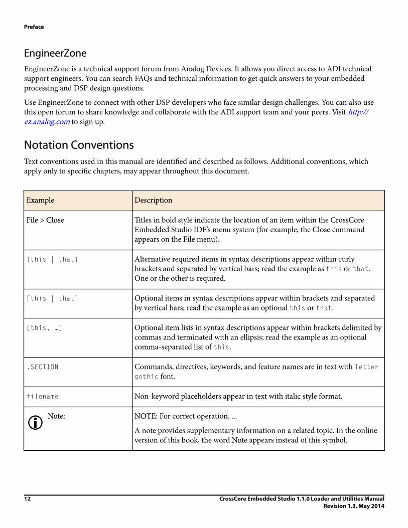
Notation ConventionsText conventions used in this manual are identified and described as follows. Additional conventions, whichapply only to specific chapters, may appear throughout this document.
Example Description
File > Close Titles in bold style indicate the location of an item within the CrossCoreEmbedded Studio IDE’s menu system (for example, the Close commandappears on the File menu).
{this | that} Alternative required items in syntax descriptions appear within curlybrackets and separated by vertical bars; read the example as this or that.One or the other is required.
[this | that] Optional items in syntax descriptions appear within brackets and separatedby vertical bars; read the example as an optional this or that.
[this, …] Optional item lists in syntax descriptions appear within brackets delimited bycommas and terminated with an ellipsis; read the example as an optionalcomma-separated list of this.
.SECTION Commands, directives, keywords, and feature names are in text with lettergothic font.
filename Non-keyword placeholders appear in text with italic style format.
iNote: NOTE: For correct operation, ...
A note provides supplementary information on a related topic. In the onlineversion of this book, the word Note appears instead of this symbol.
Preface
12 CrossCore Embedded Studio 1.1.0 Loader and Utilities ManualRevision 1.3, May 2014
Example Description
xCaution: CAUTION: Incorrect device operation may result if ...
CAUTION: Device damage may result if ...
A caution identifies conditions or inappropriate usage of the product thatcould lead to undesirable results or product damage. In the online version ofthis book, the word Caution appears instead of this symbol.
xAttention: ATTENTION Injury to device users may result if ...
A warning identifies conditions or inappropriate usage of the product thatcould lead to conditions that are potentially hazardous for devices users. Inthe online version of this book, the word Warning appears instead of thissymbol.
Preface
CrossCore Embedded Studio 1.1.0 Loader and Utilities ManualRevision 1.3, May 2014
13


2Introduction
The majority of this manual describes the loader utility (or loader) program as well as the process of loading andsplitting, the final phase of the application development flow.
Most of this chapter applies to all 8-, 16-, and 32-bit processors. Information specific to a particular processor, orto a particular processor family, is provided in the following chapters.
• Loader/Splitter for ADSP-BF50x/BF51x/BF52x/BF54x/BF59x Blackfin Processors• Loader/Splitter for ADSP-BF53x/BF561 Blackfin Processors• Loader/Splitter for ADSP-BF60x Blackfin Processors• Loader for ADSP-21160 SHARC Processors• Loader for ADSP-21161 SHARC Processors• Loader for ADSP-2126x/2136x/2137x/214xx SHARC Processors• Splitter for SHARC Processors• File Formats• Utilities
Definition of TermsLoader andLoader Utility
The term loader refers to a loader utility that is part of CrossCore Embedded Studio. Theloader utility post-processes one or multiple executable (.dxe) files, extracts segments thathave been declared by the TYPE(RAM) command in a Linker Description File (.ldf), andgenerates a loader file (.ldr). Since the .dxe file meets the Executable and Linkable Format(ELF) standard, the loader utility is often called elfloader utility. See also Loader UtilityOperations.
Splitter Utility The splitter utility is part of CrossCore Embedded Studio. The splitter utility post-processesone or multiple executable (.dxe) files, extracts segments that have been declared by theTYPE(R0M) command in a Linker Description File (.ldf), and generates a file consisting ofprocessor instructions (opcodes). If burned into an EPROM or flash memory device
Introduction
CrossCore Embedded Studio 1.1.0 Loader and Utilities ManualRevision 1.3, May 2014
15

connected to the target processor's system bus, the processor can directly fetch and executethese instructions. See also Splitter Utility Operations.
Splitter and loader jobs can be managed either by separate utility programs or by the sameprogram (see Non-Bootable Files Versus Boot-Loadable Files). In the latter case, thegenerated output file can contain code instructions and boot streams.
Loader File A loader file is generated by the loader utility. The file typically has the .ldr extension and isoften called an LDR file. Loader files can meet one of multiple formats. Common formats areIntel hex-32, binary, or ASCII representation. Regardless of the format, the loader filedescribes a boot image, which is the binary version of the loader file. See also Non-BootableFiles Versus Boot-Loadable Files.
LoaderCommand Line
If invoked from a command-line prompt, the loader and splitter utilities accept numerouscontrol switches to customize the loader file generation.
LoaderProperties Page
The loader properties page is part of the Tool Settings dialog box in the IDE. The propertiespage is a graphical tool that assists in composing the loader utility's command line.
Boot Mode Most processors support multiple boot modes. A boot mode is determined by special inputpins that are interrogated when the processor awakes from either a reset or power-downstate. See also Boot Modes.
Boot Kernel A boot kernel is software that runs on the target processor. It reads data from the boot sourceand interprets the data as defined in the boot stream format. The boot kernel can reside in anon-chip boot ROM or off-chip ROM device. Often, the kernel has to be prebooted from theboot source before it can be executed. In this case, the loader utility puts a default kernel tothe front of the boot image, or, allows the user to specify a customized kernel. See also BootKernels.
Boot ROM A boot ROM is an on-chip read-only memory that holds the boot kernel and, in some cases,additional advanced booting routines.
Second-StageLoader
A second-stage loader is a special boot kernel that extends the default booting mechanisms ofthe processor. It is typically booted by a first-stage kernel in a standard boot modeconfiguration. Afterward, it executes and boots in the final applications. See also BootKernels.
Boot Source A boot source refers to the interface through which the boot data is loaded as well as to thestorage location of a boot image, such as a memory or host device.
Boot Image A boot image that can be seen as the binary version of a loader file. Usually, it has to be storedinto a physical memory that is accessible by either the target processor or its host device.
Introduction
16 CrossCore Embedded Studio 1.1.0 Loader and Utilities ManualRevision 1.3, May 2014
Often it is burned into an EPROM or downloaded into a flash memory device using theProgrammer plug-in.
The boot image is organized in a special manner required by the boot kernel. This format iscalled a boot stream. A boot image can contain one or multiple boot streams. Sometimes theboot kernel itself is part of the boot image.
Boot Stream A boot stream is basically a list of boot blocks. It is the data structure that is processed andinterpreted by the boot kernel. The loader utility generates loader files that contain one ormultiple boot streams. A boot stream often represents one application. However, a linked listof multiple application-level boot streams is referred to as a boot stream.
Boot Host A boot host is a processor or programmable logic that feeds the device configured in a slaveboot mode with a boot image or a boot stream.
Boot Block Multiple boot blocks form a boot stream. These blocks consist of boot data that is precededby a block header. The header instructs the boot kernel how to interpret the payload data. Insome cases, the header may contain special instructions only. In such blocks, there is likelyno payload data present.
Boot Code Boot code refers to all boot-relevant ROM code. Boot code typically consists of the prebootroutine and the boot kernel.
Boot Strapping If the boot process consists of multiple steps, such as preloading the boot kernel or managingsecond-stage loaders, this is called boot strapping.
InitializationCode
Initialization code or initcode is part of a boot stream for Blackfin processors and is a specialboot block. While normally all boot blocks of an application are booted in first and control ispassed to the application afterward, the initialization code executes at boot time. It iscommon that an initialization code is booted and executed before any other boot block. Thisinitialization code can customize the target system for optimized boot processing.
Global Header Some boot kernels expect a boot stream to be headed by a special information tag. The tag isreferred to as a global header.
CallbackRoutine
Some processors can optionally call a user-defined routine after a boot block has been loadedand processed. This is referred to as a callback routine. It provides hooks to implementchecksum and decompression strategies.
Slave Boot The term slave boot spans all boot modes where the target processor functions as a slave. Thisis typically the case when a host device loads data into the target processor's memories. Thetarget processor can wait passively in idle mode or support the host-controlled data transfersactively. Note that the term host boot usually refers only to boot modes that are based on so-called host port interfaces.
Introduction
CrossCore Embedded Studio 1.1.0 Loader and Utilities ManualRevision 1.3, May 2014
17

Master Boot The term master boot spans all boot modes where the target processor functions as master.This is typically the case when the target processor reads the boot data from parallel or serialmemories.
Boot Manager A boot manager is firmware that decides which application is to be booted. An application isusually represented as a project in the IDE and stored in a .dxe file. The boot manger itselfcan be managed within an application .dxe file, or have its own separate .dxe file. Often, theboot manager is executed by initialization code.
In slave boot scenarios, boot management is up to the host device and does not requirespecial tools support.
Multi-dxe Boot A loader file can contain data of multiple application (.dxe) files if the loader utility wasinvoked by specifying multiple .dxe files. Either a boot manager decides which application isto be booted exclusively or, alternatively, one application can terminate and initiate the nextapplication to be booted. In some cases, a single application can also consist of multiple .dxefiles.
Next .dxe FilePointer
If a loader file contains multiple applications, some boot stream formats enable them to beorganized as a linked list. The next .dxe pointer (NDP) is simply a pointer to a locationwhere the next application's boot stream resides.
Preboot Routine A preboot routine is present in the boot ROM of parts that feature OTP memory on aprocessor. Preboot reads OTP memory and customizes several MMR registers based onfactory and user instructions, as programmed to OTP memory. A preboot routine executesprior to the boot kernel.
Program Development FlowThe Program Development Flow figure is a simplified view of the application development flow.
The development flow can be split into three phases:
1. Compiling and Assembling2. Linking3. Loading, Splitting, or Both
A brief description of each phase follows.
Introduction
18 CrossCore Embedded Studio 1.1.0 Loader and Utilities ManualRevision 1.3, May 2014

SOURCEFILES
ASSEMBLERAND/OR
COMPILER
.asm, .c, .cpp
PROCESSOR
LOADERAND/OR
SPLITTER
EXTERNALMEMORY
BOOTINGUPON
RESET
TARGET SYSTEM
.doj .dxe
.ldr
LINKER
Figure 1. Program Development Flow
Compiling and AssemblingInput source files are compiled and assembled to yield object files. Source files are text files containing C/C++code, compiler directives, possibly a mixture of assembly code and directives, and, typically, preprocessorcommands. The assembler and compiler are documented in the Assembler and Preprocessor Manual and C/C++Compiler Manual, which are part of the online help.
LinkingUnder the direction of the linker description file (LDF) and linker settings, the linker consumes separately-assembled object and library files to yield an executable file. If specified, the linker also produces the sharedmemory files and overlay files. The linker output (.dxe files) conforms to the ELF standard, an industry-standard format for executable files. The linker also produces map files and other embedded information(DWARF-2) used by the debugger.
These executable files are not readable by the processor hardware directly. They are neither supposed to beburned onto an EPROM or flash memory device. Executable files are intended for debugging targets, such as thesimulator or emulator. Refer to the Linker and Utilities Manual and online help for information about linkingand debugging.
Loading, Splitting, or BothUpon completing the debug cycle, the processor hardware needs to run on its own, without any debugging toolsconnected. After power-up, the processor's on-chip and off-chip memories need to be initialized. The process ofinitializing memories is often referred to as boot process, introduction to booting. Therefore, the linker outputmust be transformed to a format readable by the processor. This process is handled by the loader and/or splitterutility. The loader/splitter utility uses the debugged and tested executable files as well as shared memory andoverlay files as inputs to yield a processor-loadable file.
CrossCore Embedded Studio includes these loader and splitter utilities:
Introduction
CrossCore Embedded Studio 1.1.0 Loader and Utilities ManualRevision 1.3, May 2014
19

• elfloader.exe (loader utility) for Blackfin and SHARC processors. The loader utility for Blackfin processorsalso acts as a ROM splitter when evoked with the corresponding switches.
• elfspl21k.exe (ROM splitter utility) for earlier SHARC processors. Starting with the ADSP-214xxprocessors, splitter functionality is available through elfloader.exe.
The loader/splitter output is either a boot-loadable or non-bootable file. The output is meant to be loaded ontothe target. There are several ways to use the output:
• Download the loadable file into the processor's PROM space on an EZ-KIT Lite®/EZ-Board® board via theDevice Programmer plug-in. Refer to the online help for information on the Device Programmer.
• Use the IDE to simulate booting in a simulator session. Load the loader file and then reset the processor todebug the booting routines. No hardware is required: just point to the location of the loader file, letting thesimulator to do the rest. You can step through the boot kernel code as it brings the rest of the code intomemory.
• Store the loader file in an array for a multiprocessor system. A master (host) processor has the array in itsmemory, allowing a full control to reset and load the file into the memory of a slave processor.
Non-Bootable Files Versus Boot-Loadable FilesA non-bootable file executes from an external memory of the processor, while a boot-loadable file is transportedinto and executes from an internal memory of the processor. The boot-loadable file is then programmed into anexternal memory device (burned into EPROM) within your target system. The loader utility outputs loadablefiles in formats readable by most EPROM burners, such as Intel hex-32 and Motorola S formats. For advancedusage, other file formats and boot modes are supported. (See the File Formats appendix.)
A non-bootable EPROM image file executes from an external memory of the processor, bypassing the built-inboot mechanisms. Preparing a non-bootable EPROM image is called splitting. In most cases (except for Blackfinprocessors), developers working with floating- and fixed-point processors use the splitter instead of the loaderutility to produce a non-bootable memory image file.
A booting sequence of the processor and application program design dictate the way loader/splitter utility iscalled to consume and transform executable files:
• For Blackfin processors, loader and splitter operations are handled by the loader utility program,elfloader.exe. The splitter is invoked by a different set of command-line switches than the loader.
In the IDE, with the addition of the -readall switch, the loader utility for the ADSP-BF50x/BF51x/BF52x/BF54x/BF59x Blackfin processors can call the splitter program automatically. For more information, see -readall #.
• For earlier SHARC processors, splitter operations are handled by the splitter program, elfspl21k.exe.Starting with the ADSP-214xx processors, splitter functionality is available through elfloader.exe.
Loader Utility OperationsCommon tasks performed by the loader utility can include:
• Processing loader properties or command-line switches.
Introduction
20 CrossCore Embedded Studio 1.1.0 Loader and Utilities ManualRevision 1.3, May 2014

• Formatting the output .ldr file according to user specifications. Supported formats are binary, ASCII, Intelhex-32, and more. Valid file formats are described in the File Formats appendix.
• Packing the code for a particular data format: 8-, 16- or 32-bit for some processors.• Adding the code and data from a specified initialization executable file to the loader file, if applicable.• Adding a boot kernel on top of the user code.• If specified, preprogramming the location of the .ldr file in a specified PROM space.• Specifying processor IDs for multiple input .dxe files for a multiprocessor system, if applicable.
Using CCES Loader InterfaceRun the loader utility from the CrossCore Embedded Studio command line (elfloader) or within the IDE. Touse the loader utility for a project, the project's output (artifact) type must be a loader file (.ldr). The IDEinvokes the elfloader.exe utility to build the output loader file.
To run the loader utility within the IDE and/or modify the loader settings, use the loader pages. The pages (alsocalled properties pages) show the default loader properties for the project's target processor. The loaderproperties control how the loader utility processes executable files into boot-loadable files, letting you select andmodify kernels, boot modes, and output file formats. Settings on the loader properties pages correspond toswitches typed on the elfloader command line.
See the CCES online help for more information about the loader interface.
Splitter Utility OperationsSplitter utility operations depend on the processor family, splitter properties, and command-line switches, whichcontrol which utility is invoked, and how it processes executable files into non-bootable files:
• For Blackfin processors, the loader utility includes the ROM splitter capabilities invoked through the CCESIDE or command line. The IDE settings correspond to switches typed on the elfloader command line. Referto the CCES online help for more information.
• For SHARC processors earlier than ADSP-214xx, the splitter functionality is available in CCES via thecommand-line (elfspl21k.exe). Refer to the Splitter for SHARC Processors chapter for more information.
• For SHARC ADSP-214xx processors, the loader utility includes section splitting capabilities via the -splitterswitch.). Refer to the Splitter for SHARC Processors chapter for more information.
Using CCES Splitter InterfaceFor Blackfin and SHARC processors, use the splitter capabilities of the loader from the CrossCore EmbeddedStudio command line (elfloader) or within the IDE. To use the splitter capabilities for a project, the project'soutput (artifact) type must be a loader file (.ldr). The IDE invokes the elfloader.exe utility to build theoutput loader file.
For Blackfin processors, use the CCES splitter page. The page (also called properties page) show the defaultsplitter properties for the project's target processor. The properties control how the loader utility processesexecutable files into non-bootable files, letting you select and modify address masks, data packing options, andoutput file formats.
Introduction
CrossCore Embedded Studio 1.1.0 Loader and Utilities ManualRevision 1.3, May 2014
21

For the ADSP-214xx SHARC processors, use the CCES Additional Options properties page of the loader andspecify the -splittersection-name switch.
Settings on the properties pages correspond to switches typed on the elfloader command line. See the CCESonline help for more information about the loader/splitter interface.
Boot ModesOnce an executable file is fully debugged, the loader utility is ready to convert the executable file into a processor-loadable (boot-loadable) file. The loadable file can be automatically downloaded (booted) to theprocessor after power-up or after a software reset. The way the loader utility creates a boot-loadable file dependsupon how the loadable file is booted into the processor.
The boot mode of the processor is determined by sampling one or more of the input flag pins. Bootingsequences, highly processor-specific, are detailed in the following chapters.
Analog Devices processors support different boot mechanisms. In general, the following schemes can be used toprovide program instructions to the processors after reset.
• No-Boot Mode• PROM Boot Mode• Host Boot Mode
No-Boot ModeAfter reset, the processor starts fetching and executing instructions from EPROM/flash memory devices directly.This scheme does not require any loader mechanism. It is up to the user program to initialize volatile memories.
The splitter utility generates a file that can be burned into the PROM memory.
PROM Boot ModeAfter reset, the processor starts reading data from a parallel or serial PROM device. The PROM stores aformatted boot stream rather than raw instruction code. Beside application data, the boot stream containsadditional data, such as destination addresses and word counts. A small program called a boot kernel (describedin Boot Kernels) parses the boot stream and initializes memories accordingly. The boot kernel runs on the targetprocessor. Depending on the architecture, the boot kernel may execute from on-chip boot RAM or may bepreloaded from the PROM device into on-chip SRAM and execute from there.
The loader utility generates the boot stream from the linker output (an executable file) and stores it to file formatthat can be burned into the PROM.
Host Boot ModeIn this scheme, the target processor is a slave to a host system. After reset, the processor delays programexecution until the slave gets signaled by the host system that the boot process has completed. Depending onhardware capabilities, there are two different methods of host booting. In the first case, the host system has full
Introduction
22 CrossCore Embedded Studio 1.1.0 Loader and Utilities ManualRevision 1.3, May 2014

control over all target memories. The host halts the target while initializing all memories as required. In thesecond case, the host communicates by a certain handshake with the boot kernel running on the targetprocessor. This kernel may execute from on-chip ROM or may be preloaded by the host devices into theprocessor's SRAM by any bootstrapping scheme.
The loader/splitter utility generates a file that can be consumed by the host device. It depends on the intelligenceof the host device and on the target architecture whether the host expects raw application data or a formatted boot stream. In this context, a boot-loadable file differs from a non-bootable file in that it stores instruction codein a formatted manner in order to be processed by a boot kernel. A non-bootable file stores raw instruction code.
Boot KernelsA boot kernel refers to the resident program in the boot ROM space responsible for booting the processor.Alternatively (or in absence of the boot ROM), the boot kernel can be preloaded from the boot source by a bootstrapping scheme.
When a reset signal is sent to the processor, the processor starts booting from a PROM, host device, or through acommunication port. For example, an ADSP-2116x processor, brings a 256-word program into internal memoryfor execution. This small program is a boot kernel.
The boot kernel then brings the rest of the application code into the processor's memory. Finally, the boot kerneloverwrites itself with the final block of application code and jumps to the beginning of the application program.
Some of the newer Blackfin processors do not require to load a boot kernel-a kernel is already present in the on-chip boot ROM. It allows the entire application program's body to be booted into the internal and externalmemories of the processor. The boot ROM has the capability to parse address and count information for eachbootable block.
Boot StreamsThe loader utility's output (.ldr file) is essentially the same executable code as in the input .dxe file; the loaderutility simply repackages the executable as shown in the .dxe Files Versus .ldr Files figure.
Processor code and data in a loader file (also called a boot stream) is split into blocks. Each code block is markedwith a tag that contains information about the block, such as the number of words and destination in theprocessor's memory. Depending on the processor family, there can be additional information in the tag.Common block types are "zero" (memory is filled with 0s); nonzero (code or data); and final (code or data).Depending on the processor family, there can be other block types.
Introduction
CrossCore Embedded Studio 1.1.0 Loader and Utilities ManualRevision 1.3, May 2014
23

.LDR FILE
CODE
DATA
SYMBOLS
DEBUGINFORMATION
.DXE FILE
CODE
DATA
SYMBOLS
DEBUGINFORMATION
A .DXE FILE INCLUDES: - DSP INSTRUCTIONS (CODE AND DATA) - SYMBOL TABLE AND SECTION INFORMATION - TARGET PROCESSOR MEMORY LAYOUT - DEBUG INFORMATION
AN .LDR FILE INCLUDES: - DSP INSTRUCTIONS (CODE AND DATA ) - RUDIMENTARY FORMATTING (ALL DEBUG INFORMATION HAS BEEN REMOVED)
Figure 2. .dxe Files Versus .ldr Files
Loader File SearchesFile searches are important in the loader utility operations. The loader utility supports relative and absolutedirectory names and default directories. File searches occur as follows.
• Specified path-If relative or absolute path information is included in a file name, the loader utility searchesonly in that location for the file.
• Default directory-If path information is not included in the file name, the loader utility searches for the file inthe current working directory.
• Overlay and shared memory files-The loader utility recognizes overlay and shared memory files but does notexpect these files on the command line. Place the files in the directory that contains the executable file thatrefers to them, or place them in the current working directory. The loader utility can locate them whenprocessing the executable file.
When providing an input or output file name as a loader/splitter command-line parameter, use these guidelines:
• Enclose long file names within straight quotes, "long file name".• Append the appropriate file extension to each file.
Loader File ExtensionsSome loader switches take a file name as an optional parameter. The File Extensions table lists the expected filetypes, names, and extensions.
Introduction
24 CrossCore Embedded Studio 1.1.0 Loader and Utilities ManualRevision 1.3, May 2014

Table 1. File Extensions
Extension File Description
.dxe Loader input files, boot kernel files, and initialization files
.ldr Loader output file
.knl Loader output files containing kernel code only when two output files are selected
In some cases, the loader utility expects the overlay input files with the .ovl file extension, shared memory inputfiles with the .sm extension, or both but does not expect those files to appear on a command line or propertiespages. The loader utility expects to find these files in the directory of the associated .dxe files, in the currentworking directory, or in the directory specified for the .ldf file.
Introduction
CrossCore Embedded Studio 1.1.0 Loader and Utilities ManualRevision 1.3, May 2014
25


3Loader/Splitter for ADSP-BF50x/BF51x/BF52x/BF54x/BF59x Blackfi Processors
This chapter explains how the loader/splitter utility (elfloader.exe) is used to convert executable (.dxe) filesinto boot-loadable or non-bootable files for the ADSP-BF50x, ADSP-BF51x, ADSP-BF52x, ADSP-BF54x, andADSP-BF59x Blackfin processors.
Refer to the Introduction chapter for the loader utility overview. Loader operations specific to the ADSP-BF50x/BF51x/BF52x/BF54x and ADSP-BF59x Blackfin processors are detailed in the following sections.
• ADSP-BF50x/BF51x/BF52x/BF54x/BF59x Processor Booting
Provides general information on various boot modes, including information on second-stage kernels.• ADSP-BF50x/BF51x/BF52x/BF54x/BF59x Processor Loader Guide
Provides reference information on the loader utility's command-line syntax and switches.
ADSP-BF50x/BF51x/BF52x/BF54x/BF59x Processor BootingRefer to the processor's data sheet and hardware reference manual for detailed information on systemconfiguration, peripherals, registers, and operating modes.
• Blackfin processor data sheets can be found at:
http://www.analog.com/en/embedded-processing-dsp/blackfin/processors/data-sheets/resources/index.html.• Blackfin processor manuals can be found at:
http://www.analog.com/en/embedded-processing-dsp/blackfin/processors/manuals/resources/index.html ordownloaded into the CCES IDE via Help > Install New Software.
The following table lists the part numbers that currently comprise the ADSP-BF50x/BF51x/BF52x/BF54x/BF59xfamilies of Blackfin processors. Future releases of CrossCore Embedded Studio may support additionalprocessors.
Loader/Splitter for ADSP-BF50x/BF51x/BF52x/BF54x/BF59x Blackfin Processors
CrossCore Embedded Studio 1.1.0 Loader and Utilities ManualRevision 1.3, May 2014
27

Table 2. ADSP-BF50x/BF51x/BF52x/BF54x/BF59x Part Numbers
Processor Family Part Numbers
ADSP-BF504 ADSP-BF504, ADSP-BF504F, ADSP-BF506
ADSP-BF518 ADSP-BF512, ADSP-BF514, ADSP-BF516, ADSP-BF518
ADSP-BF526 ADSP-BF522, ADSP-BF524, ADSP-BF526
ADSP-BF527 ADSP-BF523, ADSP-BF525, ADSP-BF527
ADSP-BF548 ADSP-BF542, ADSP-BF544, ADSP-BF547, ADSP-BF548, ADSP-BF549
ADSP-BF548M ADSP-BF542M, ADSP-BF544M, ADSP-BF547M, ADSP-BF548M, ADSP-BF549M
ADSP-BF592 ADSP-BF592-A
Upon reset, an ADSP-BF50x/BF51x/BF52x/BF54x/BF59x processor starts fetching and executing instructionsfrom the on-chip boot ROM at address 0xEF00 0000. The boot ROM is an on-chip read-only memory thatholds a boot kernel program to load data from an external memory or host device. The boot ROM details can befound in the corresponding hardware reference manual.
There are other boot modes available, including idle (no-boot) mode. The processor transitions into the bootmode sequence configured by the BMODE pins; see the ADSP-BF50x Boot Modes, ADSP-BF51x Boot Modes,ADSP-BF52x/BF54x, andADSP-BF59x Boot Modes tables. The BMODE pins are dedicated mode-control pins; thatis, no other functions are performed by the pins. The pins can be read through bits in the system configurationregister (SYSCR).
Table 3. ADSP-BF50x Boot Modes
Boot Source BMODE[2:0] Start Address
Idle (no-boot) 000 N/A
Stacked parallel flash memory in async mode 0011 0x2000 0000
Stacked parallel flash memory in sync burst mode 010 0x2000 0000
SPI0 master from SPI memory 011 0x0000 0000
1 ADSP-BF504 processors do not support BMODE 001 or 010 because they have no internal flash.
Loader/Splitter for ADSP-BF50x/BF51x/BF52x/BF54x/BF59x Blackfin Processors
28 CrossCore Embedded Studio 1.1.0 Loader and Utilities ManualRevision 1.3, May 2014

Boot Source BMODE[2:0] Start Address
SPI0 slave from host device 100 N/A
16-bit PPI host 101 N/A
Reserved 110 N/A
UART0 slave from UART host 111 N/A
Table 4. ADSP-BF51x Boot Modes
Boot Source BMODE[2:0] Start Address
Idle (no-boot) 000 N/A
8- or 16-bit external flash memory (default mode) 001 0x2000 0000
Internal SPI memory 010 0x2030 0000
External SPI memory (EEPROM or flash) 011 0x0000 0000
SPI0 host device 100 N/A
One-time programmable (OTP) memory 101 N/A
SDRAM memory 110 N/A
UART0 host 111 N/A
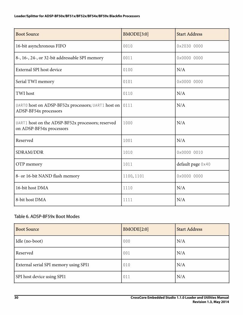
Table 5. ADSP-BF52x/BF54x Boot Modes
Boot Source BMODE[3:0] Start Address
Idle (no-boot) 0000 N/A
8- or 16-bit external flash memory (default mode) 0001 0x2000 0000
Loader/Splitter for ADSP-BF50x/BF51x/BF52x/BF54x/BF59x Blackfin Processors
CrossCore Embedded Studio 1.1.0 Loader and Utilities ManualRevision 1.3, May 2014
29
Boot Source BMODE[3:0] Start Address
16-bit asynchronous FIFO 0010 0x2030 0000
8-, 16-, 24-, or 32-bit addressable SPI memory 0011 0x0000 0000
External SPI host device 0100 N/A
Serial TWI memory 0101 0x0000 0000
TWI host 0110 N/A
UART0 host on ADSP-BF52x processors; UART1 host onADSP-BF54x processors
0111 N/A
UART1 host on the ADSP-BF52x processors; reservedon ADSP-BF54x processors
1000 N/A
Reserved 1001 N/A
SDRAM/DDR 1010 0x0000 0010
OTP memory 1011 default page 0x40
8- or 16-bit NAND flash memory 1100, 1101 0x0000 0000
16-bit host DMA 1110 N/A
8-bit host DMA 1111 N/A
Table 6. ADSP-BF59x Boot Modes
Boot Source BMODE[2:0] Start Address
Idle (no-boot) 000 N/A
Reserved 001 N/A
External serial SPI memory using SPI1 010 N/A
SPI host device using SPI1 011 N/A
Loader/Splitter for ADSP-BF50x/BF51x/BF52x/BF54x/BF59x Blackfin Processors
30 CrossCore Embedded Studio 1.1.0 Loader and Utilities ManualRevision 1.3, May 2014

Boot Source BMODE[2:0] Start Address
External serial SPI memory using SPI0 100 N/A
PPI host 101 N/A
UART host 110 N/A
Internal L1 ROM 111 0x2000 0000
In general, there are two categories of boot modes: master and slave. In master boot modes, the processoractively loads data from parallel or serial memory devices. In slave boot modes, the processor receives data fromparallel or serial memory devices.
The Blackfin loader utility generates .ldr files that meet the requirements of the target boot mode; for example:
• HOSTDP (-b HOSTDP)
When building for the HOSTDP boot, the loader utility aligns blocks with payload to the appropriate FIFOdepth for the target processor. Note that HOSTDP differs from other boot modes in the default setting for the -NoFillBlock switch. The HOSTDP boot mode directs the loader not to produce fill (zero) blocks by default.
To enable fill blocks for HOSTDP builds in the CCES IDE:
1. Open the Properties dialog box for the project.2. Choose C/C++ Build > Settings. The Tool Settings page appears.3. Click Additional Options under CrossCore Blackfin Loader. The loader Additional Options properties page
appears.4. Click Add (+). The Enter Value dialog box appears.5. In Additional Options, type in -FillBlock.6. Click OK to close the dialog box.7. Click Apply.
• NAND (-b NAND)
When building for NAND boot, the loader utility appends 256 bytes to the boot NAND loader stream, arequirement for the boot kernel for the prefetch mechanism. While fetching one 256 byte block of data, itprefetches the next 256 byte block of data. The padding ensures that the final block of the loader stream isprogrammed, and the error correction parity data is written.
• OTP (-b OTP)
When building for OTP boot, no width selection is used. OTP is always a 32-bit internal transfer. Use Intelhex-32 format for the OTP boot mode and provide the offset to the start address for the OTP page. The OTPflash programmer requires the offset to the start address for the OTP page when Intel hex loader format isselected. To specify the start address in the CCES IDE:
1. Open the Properties dialog box for the project.2. Choose C/C++ Build > Settings. The Tool Settings page appears.
Loader/Splitter for ADSP-BF50x/BF51x/BF52x/BF54x/BF59x Blackfin Processors
CrossCore Embedded Studio 1.1.0 Loader and Utilities ManualRevision 1.3, May 2014
31

3. Click General under CrossCore Blackfin Loader. The loader General properties page appears.4. In Boot format (-f), ensure Intel hex is selected.5. Disable Use default start kernel. The Start address (-p) is enabled.6. In Start address (-p), enter the page number multiplied by 16. For example, if you are building for OTP boot
and writing to page 0x40L, specify start address 0x400.7. Click Apply.
On the loader command-line, the above example corresponds to:
-b otp -f hex -p 0x400
Refer to the CCES online help for information about the loader properties pages.
ADSP-BF50x/BF51x/BF52x/BF54x/BF59x Processor Loader GuideLoader utility operations depend on the loader properties, which control how the utility processes executablefiles. You select features, such as boot modes, boot kernels, and output file formats via the properties. Theproperties are specified on the loader utility's command line or the Tool Settings dialog box in the IDE(CrossCore Blackfin Loader pages). The default loader settings for a selected processor are preset in the IDE.
iNote:
The IDE’s Tool Settings correspond to switches displayed on the command line.
These sections describe how to produce a bootable (single and multiple) or non-bootable loader file:
• Loader Command Line for ADSP-BF50x/BF51x/BF52x/BF54x/BF59x Processors• CCES Loader and Splitter Interface for ADSP-BF50x/BF51x/BF52x/BF54x/BF59x Processors
Loader Command Line for ADSP-BF50x/BF51x/BF52x/BF54x/BF59x ProcessorsThe loader utility uses the following command-line syntax for the ADSP-BF50x/BF51x/BF52x/BF54x/BF59xBlackfin processors.
For a single input file:
elfloader inputfile -proc processor [-switch]
For multiple input files:
elfloader inputfile1 inputfile2 -proc processor [-switch]
where:
• inputfile - Name of the executable (.dxe) file to be processed into a single boot-loadable or non-bootablefile. An input file name can include the drive and directory. For multiprocessor or multi-input systems, specifymultiple input .dxe files. Put the input file names in the order in which you want the loader utility to processthe files. Enclose long file names within straight quotes, "long file name".
• -proc processor - Part number of the processor (for example, -proc ADSP-BF542) for which the loadablefile is built. Provide a processor part number for every input .dxe if designing multiprocessor systems; see thepart numbers in ADSP-BF50x/BF51x/BF52x/BF54x/BF59x Processor Booting.
Loader/Splitter for ADSP-BF50x/BF51x/BF52x/BF54x/BF59x Blackfin Processors
32 CrossCore Embedded Studio 1.1.0 Loader and Utilities ManualRevision 1.3, May 2014

• -switch - One or more optional switches to process. Switches select operations and modes for the loaderutility.
iNote:
Command-line switches can be placed on the command line in any order, except the order of input filesfor a multi-input system. For a multi-input system, the loader utility processes the input files in the orderpresented on the command line.
Loader Command-Line Switches for ADSP-BF50x/BF51x/BF52x/BF54x/BF59xA summary of the loader command-line switches for the ADSP-BF50x/BF51x/BF52x/BF54x/BF59x Blackfinprocessors appears in the following table. For a quick on-line help on the switches available for a specificprocessor: for an ADSP-BF548 processor, use the following command line.
elfloader -proc ADSP-BF548 -help
Table 7. ADSP-BF50x/BF51x/BF52x/BF54x/BF59x Loader Command-Line Switches
Switch Description
-b {flash|prom|spimaster|spislave|twimaster|twislave|uart|fifo|otp|nand|ppi|hostdp}
The -b switch directs the loader utility to prepare a boot-loadablefile for the specified boot mode. The default boot mode for allprocessors described in this chapter is PROM/FLASH.
Other valid boot modes include:
• SPI master (-b spimaster) for the ADSP-BF50x,BF51x/52x/54x/54xM, and ADSP-BF59x processors.
• SPI slave (-b spislave) for the ADSP-BF50x, BF51x/52x/54x/54xM, and ADSP-BF59x processors.
• UART (-b uart) for the ADSP-BF50x, BF51x/52x/54x/54xM,and ADSP-BF59x processors.
• TWI master (-b twimaster) for the ADSP-BF52x/54x/54xMprocessors.
• TWI slave (-b twislave) for the ADSP-BF52x/54x/54xMprocessors.
• FIFO (-b fifo) for the ADSP-BF52x/54x/54xM processors.• OTP (-b otp) for the ADSP-BF51x/52x/54x/54xM processors.• NAND (-b nand) for the ADSP-BF52x/54x/54xM processors.• PPI (-b ppi) - for the ADSP-BF50x and BF59x processors.• HOSTDP (-b hostdp) for the ADSP-BF52x, BF544/7/8/9, and
BF544M/547M/548M/549M processors.
See additional information in this chapter on the HOSTDP,NAND, and OTP boot modes.
Loader/Splitter for ADSP-BF50x/BF51x/BF52x/BF54x/BF59x Blackfin Processors
CrossCore Embedded Studio 1.1.0 Loader and Utilities ManualRevision 1.3, May 2014
33

Switch Description
-CRC32 [polynomial] The -CRC32 (polynomial coefficient) switch directs the loaderutility to generate CRC32 checksum. Use a polynomial coefficientif specified; otherwise, use default 0xD8018001.
This switch inserts an initcode boot block that calls aninitialization routine residing in the on-chip boot ROM. Theargument field of the boot block provides the used polynomial.The loader utility calculates the CRC checksum for all subsequentdata blocks and stores the result in the block header's argumentfield.
-callback sym=symbol[arg=const32 ]
The -callback switch takes a sym=symbol (no spaces)assignment.
The switch directs the loader utility to isolate the namedsubroutine into a separate block, set the block header's BFLAG_CALLBACK flag, and fill in the block header's argument fieldwith the specified constant 32-bit values. The switch is used forboot-time callbacks.
The callback is guaranteed to be made prior to the target addressof sym=symbol.
iNote:
The -callback cannot be used with -CRC32.
-dmawidth {8|16|32}
The -dmawidth {8|16|32} switch specifies a DMA width (inbits) for memory boot modes. It controls the DMACODE bit fieldissued to the boot block headers by the -width switch.
For FIFO boot mode, 16 is the only DMA width. SPI, TWI, andUART modes use 8-bit DMA.
-f {hex|ascii|binary|include}
The -f {hex|ascii|binary|include} switch specifies the format of a boot-loadable file: Intel hex-32, ASCII, binary, or include. If the -f switch does not appear on the command line,the default file format is hex for flash/PROM boot modes; andASCII for other boot modes.
-FillBlock FILL blocks are enabled by default for all boot modes, except -bhostdp.
Loader/Splitter for ADSP-BF50x/BF51x/BF52x/BF54x/BF59x Blackfin Processors
34 CrossCore Embedded Studio 1.1.0 Loader and Utilities ManualRevision 1.3, May 2014

Switch Description
-h or -helpThe -help switch invokes the command-line help, outputs a list ofcommand-line switches to standard output, and exits. By default,the -h switch alone provides help for the loader driver. To obtain ahelp screen for your target Blackfin processor, add the -procswitch to the command line. For example, type elfloader -procADSP-BF542 -h to obtain help for the ADSP-BF542 processor.
-init filename.dxeThe -init filename.dxe switch directs the loader utility toinclude the initialization code from the named executable file. Theloader utility places the code and data from the initializationsections at the top of the boot stream. The boot kernel loads thecode and then calls it. It is the code's responsibility to save/restorestate/registers and then perform an RTS back to the kernel.Initcodes can be written in C language and are compliant to Ccalling conventions.
The -init filename.dxe switch can be used multiple times tospecify the same file or different files a number of times. Theloader utility will place the code from the initialization files in theorder the files appear on the command line.
ADSP-BF50x/BF51x/BF52x/BF54x/BF59x Multi-DXE LoaderFiles
-initcall sym=sym_symbol
at=at_symbol [stride=DstAddrGapcount=times]
While the -init filename.dxe switch integrates initializationcodes managed by a separate application program, the -initcallswitch controls calls to initialization subroutines that are part ofthe same application.
The -initcall switch directs the loader utility to dispatch aboot-time initialization call to the sym subroutine when the atsymbol is encountered and loaded. The stride and countparameters are optional:
• If an optional stride= constant 32-bit value is specified, theloader utility insets the target program call every stride= targetaddress locations.
• If an optional count= constant 32-bit value is specified, theloader utility insets the target program call count= times, everystride= target address locations apart. A count value without astride value is an error.
For example, the following command line:
Loader/Splitter for ADSP-BF50x/BF51x/BF52x/BF54x/BF59x Blackfin Processors
CrossCore Embedded Studio 1.1.0 Loader and Utilities ManualRevision 1.3, May 2014
35

Switch Description
-initcall sym=_initcode at=_othersymbol stride=0x100count=5
results in function _initcode being called five times the firsttime, just prior to data in _othersymbol being booted.Thereafter, every 256 destination load addresses _initcode iscalled again until a total of five calls have been made.
-initcall restrictions:
• -initcall target (sym_symbol) must be a routine entry point,end with an RTS. It can be written in C language and can rely onthe presence of a stack. However, the routine must not call anylibraries, not rely on compiler run-time environment (such asheaps) - must be self-contained
• -initcall subroutine must be previously loaded and still inmemory
• -initcall subroutine cannot contain any forward references tocode not yet loaded
• sym_symbol address must be less than at_symbol address
For more information, see ADSP-BF50x/BF51x/BF52x/BF54x/BF59x Multi-DXE Loader Files.
-kb {flash|prom|spimaster|spislave|uart|twimaster|twislave|fifo|nand|ppi}
The -kb switch specifies the boot mode for the initialization codeand/or boot kernel output file if two output loader files areselected.
The -kb switch must be used in conjunction with the -o2 switch.
If the -kb switch is absent from the command line, the loaderutility generates the file for the init and/or boot kernel code in thesame boot mode as used to output the user application program.
Other valid boot modes include:
• PROM/FLASH (-kb prom or -kb flash) - the default bootmode for all processors described in this chapter.
• SPI master (-kb spimaster) for the ADSP-BF50x,BF51x/52x/54x/54xM, and ADSP-BF59x processors.
• SPI slave (-kb spislave) for the ADSP-BF50x, BF51x/52x/54x/54xM, and ADSP-BF59x processors.
• UART (-kb uart) for the ADSP-BF50x, BF51x/52x/54x/54xM,and ADSP-BF59x processors.
Loader/Splitter for ADSP-BF50x/BF51x/BF52x/BF54x/BF59x Blackfin Processors
36 CrossCore Embedded Studio 1.1.0 Loader and Utilities ManualRevision 1.3, May 2014

Switch Description
• TWI master (-kb twimaster) for the ADSP-BF52x/54x/54xMprocessors.
• TWI slave (-kb twislave) for the ADSP-BF52x/54x/54xMprocessors.
• FIFO (-kb fifo) for the ADSP-BF52x/54x/54xM processors.• NAND (-kb nand) - for the ADSP-BF52x/54x/54xM
processors.• PPI (-kb ppi) for the ADSP-BF50x and BF59x processors.
-kf {hex|ascii|binary|include} The -kf {hex|ascii|binary|include} switch specifies theoutput file format (hex, ASCII, binary, include) for theinitialization and/or boot kernel code if two output files from theloader utility are selected: one file for the init code and/or bootkernel and one file for user application code.
The -kf switch must be used in conjunction with the-o2 switch.
If -kf is absent from the command line, the loader utilitygenerates the file for the initialization and /or boot kernel code inthe same format as for the user application code.
-kp #The -kp # switch specifies a hex flash/PROM start address for theinitialization and/or boot kernel code. A valid value is between0x0 and 0xFFFFFFFF. The specified value is ignored when neitherkernel nor initialization code is included in the loader file.
-kwidth {8|16|32}
The -kwidth {8|16|32} switch specifies an external memorydevice width (in bits) for the initialization code and/or the boot kernel if two output files from the loader utility are selected.
If -kwidth is absent from the command line, the loader utilitygenerates the boot kernel file in the same width as the userapplication program.
The -kwidth # switch must be used in conjunction with the -o2switch.
-l userkernel.dxe The -l userkernel.dxe switch specifies the user boot kernel file.
There is no default kernel for the ADSP-BF50x/BF51x/BF52x/BF54x/BF59x processors.
Loader/Splitter for ADSP-BF50x/BF51x/BF52x/BF54x/BF59x Blackfin Processors
CrossCore Embedded Studio 1.1.0 Loader and Utilities ManualRevision 1.3, May 2014
37

Switch Description
-M The -M switch generates make dependencies only, no output file isgenerated.
-maskaddr # The -maskaddr # switch masks all EPROM address bits above orequal to #. For example, -maskaddr 29 (default) masks all thebits above and including A29 (ANDed by 0x1FFF FFFF). Forexample, 0x2000 0000 becomes 0x0000 0000. The valid #s areintegers 0 through 32, but based on your specific input file, thevalue can be within a subset of [0, 32].
The -maskaddr# switch requires -romsplitter and affects theROM section address only.
-MaxBlockSize # The -MaxBlockSize # switch specifies the maximum block sizeup to 0x7FFFFFF0. The value must be a multiple of 4.
The default maximum block size is 0xFFF0 or the value specifiedby the -MaxBlockSize switch.
-MaxFillBlockSize # The -MaxFillBlockSize # switch specifies the maximum fillblock size up to 0xFFFFFF0. The value must be a multiple of two.The default fill block size is 0xFFF0.
-MM The -MM switch generates make dependencies while producing theoutput files.
-Mo filename The -Mo filename switch writes make dependencies to thenamed file. Use the -Mo switch with either -M or -MM. If -Mo isabsent, the default is a <stdout> display.
-Mt targetThe -Mt target switch specifies the make dependencies targetoutput file. Use the -Mt switch with either -M or -MM. If -Mt is notpresent, the default is the name of the input file with an .ldrextension.
-NoFillBlock The -NoFillBlock switch directs the loader utility not to produceFILL blocks, zero, or repeated blocks.
The -NoFillBlock switch is set automatically in the HOSTDP (-b HOSTDP) boot mode.
Loader/Splitter for ADSP-BF50x/BF51x/BF52x/BF54x/BF59x Blackfin Processors
38 CrossCore Embedded Studio 1.1.0 Loader and Utilities ManualRevision 1.3, May 2014

Switch Description
-NoInitCode The -NoInitCode switch directs the loader utility not to expectan init code file. The loader utility may expect an init code file,specified through the -init filename.dxe switch if theapplication has an external memory section. The init code fileshould contain the code to initialize registers for external memoryinitialization.
-o filename The -o filename switch directs the loader utility to use thespecified file as the name of the loader utility's output file. If thefilename is absent, the default name is the root name of theinput file with an .ldr extension.
-o2 The -o2 switch directs the loader utility to produce two outputfiles: one file for code from the initialization block and/or bootkernel and one file for user application code.
To have a different format, boot mode, or output width for theapplication code output file, use the -kb -kf -kwidth switchesto specify the boot mode, the boot format, and the boot width forthe output kernel file, respectively.
Combine -o2 with -l filename and/or -init filename.dxe.
-p # The -p # switch specifies a hex flash/PROM output start addressfor the application code. A valid value is between 0x0 and0xFFFFFFFF. A specified value must be greater than that specifiedby -kp if both kernel and/or initialization and application codeare in the same output file (a single output file).
For boot mode -b OTP and -f hex format, use -p to supply theoffset to the start address for the OTP page (page # multiplied by16).
-proc processor The -proc processor switch specifies the target processor.
The processor can be one of the processors listed in the ADSP-BF50x/BF51x/BF52x/BF54x/BF59x Part Numbers table in ADSP-BF50x/BF51x/BF52x/BF54x/BF59x Processor Booting.
-quickboot sec=section The -quickboot switch takes a sec=section (no spaces)assignment.
Loader/Splitter for ADSP-BF50x/BF51x/BF52x/BF54x/BF59x Blackfin Processors
CrossCore Embedded Studio 1.1.0 Loader and Utilities ManualRevision 1.3, May 2014
39

Switch Description
The switch directs the loader utility to mark blocks within theLDF-defined output section name with theBFLAG_QUICKBOOTflag. The switch is used to mark blocks to skip on warm-bootcycles.
-readall #The -readall # switch directs the loader utility to integrate fixed-position ROM sections within the loader boot stream. The switchcalls the splitter utility as a transparent sub-process to the loaderutility. Memory segments declared with the TYPE(ROM) commandin the LDF file are processed by the splitter. Segments with theTYPE(RAM) command emit to the boot stream.
The valid switch argument is an integer between 0 and 32, where29 is the default. In the resulting loader (.ldr) file in Intel hex-32format, the ROM-based splitter data is merged with the RAM-based loader stream.
The # argument is similar to the -maskaddr # switch, whichdesignates the upper PROM address bit position for extendedaddress mapping. The splitter utility is required to provide the -maskaddr # parameter to the loader utility to generate a ROM-based splitter stream, but the required splitter parameter is notavailable on the loader command line. The loader utility solvesthis requirement by supporting the -readall# switch.
-romsplitter
The -romsplitter switch creates a non-bootable image only.This switch overwrites the -b switch and any other switchbounded by the boot mode.
In the .ldf file, declare memory segments to be `split' as typeROM. The splitter skips RAM segments, resulting in an empty file ifall segments are declared as RAM. The -romsplitter switchsupports Intel hex and ASCII formats.
-save [sec=section] The -save switch takes a sec=section (no spaces) assignment.
The switch directs the loader utility to mark blocks within theLDF-defined section name with the BFLAG_SAVE flag. The switchis used to mark blocks to archive for low-power or power-failcycles.
Loader/Splitter for ADSP-BF50x/BF51x/BF52x/BF54x/BF59x Blackfin Processors
40 CrossCore Embedded Studio 1.1.0 Loader and Utilities ManualRevision 1.3, May 2014

Switch Description
-si-revision [none|any|x.x] Sets revision for the build, with x.x being the revision number forthe processor hardware. If -si-revision is not used, the target isa default revision from the supported revisions.
-v The -v switch directs the loader utility to output verbose loadermessages and status information as the loader processes files.
-width {8|16|32} The -width {8|16|32} switch specifies an external memorydevice width (in bits) to the loader utility in flash/PROM bootmode (default is 8). For FIFO boot mode, the only valid width is16. For SPI, TWI, and UART boot modes, the only valid width is8.
ADSP-BF50x/BF51x/BF52x/BF54x/BF59x Multi-DXE Loader FilesAn ADSP-BF50x/BF51x/BF52x/BF54x/BF59x loader (.ldr) file can contain data of multiple application (.dxe)files. At boot time, the boot kernel boots one application file exclusively, or one application file initiates the bootof the next application file. In some cases, a single application can consist of multiple .dxe files.
Initialization code is a subroutine called at boot time. Unlike the ADSP-BF53x/BF56x processors, the ADSP-BF50x/BF51x/BF52x/BF54x/BF59x processors support initcode written in both assembly and C.
CrossCore Embedded Studio supports two methods of integrating multiple initcode subroutines:
• The -init filename.dxecommand-line switch expects a .dxe file. The initcode is managed by a separateproject. If the initcode is written in C language, ensure that the .dxe file does not include the CRT codebecause the boot kernel expects a subroutine.
The -init filename.dxe switch can be used multiple times to specify the same file or different files a numberof times. The loader utility places the code from the initialization files in the order the files appear on thecommand line. All initcodes are inserted after the first regular .dxe file.
The loader utility equips every initcode with a dedicated first boot block, which has the BFLAG_FIRST flag set.Initcodes, however, do not feature a final block; they are terminated by a boot block, tagged by the BFLAG_INITflag. Therefore, in absence of the BFLAG_FINAL flag, the boot kernel continues processing of thesubsequent .dxe data after finishing execution of the initcode.
• The -initcall sym=sym_symbolcommand-line switch relies on initcode subroutines that are part of thesame project. Initcode subroutines invoked by the -initcall switch are not accompanied by any first bootblocks with the BFLAG_FIRST flag set. In the loader file, the initcode subroutines translate to boot blockstagged by the BFLAG_INIT flag.
When writing an initcode subroutine in C, ensure that the code does not rely on libraries or heap support, whichmay not be available in memory by the time the initcode executes. An initcode routine is expected to return
Loader/Splitter for ADSP-BF50x/BF51x/BF52x/BF54x/BF59x Blackfin Processors
CrossCore Embedded Studio 1.1.0 Loader and Utilities ManualRevision 1.3, May 2014
41

properly to the boot kernel by an RTS instruction and to meet C-language calling conventions (see the C/C++Compiler and Library Manual for Blackfin Processors).
Refer to the initcode examples provided with the installation in <install_path>/Blackfin/ldr/init_code.
CCES Loader and Splitter Interface for ADSP-BF50x/BF51x/BF52x/BF54x/BF59xProcessorsOnce a project is created in the CrossCore Embedded Studio IDE, you can change the project's output (artifact)type.
The IDE invokes the elfloader.exe utility to build the output loader file. To modify the default loaderproperties, use the project's Tool Settings dialog box. The controls on the pages correspond to the loadercommand-line switches and parameters (see Loader Command-Line Switches for ADSP- BF50x/BF51x/BF52x/BF54x/BF59x). The loader utility for Blackfin processors also acts as a ROM splitter when evoked with thecorresponding switches.
The loader pages (also called loader properties pages) show the default loader settings for the project's targetprocessor. Refer to the CCES online help for information about the loader/splitter interface.
Loader/Splitter for ADSP-BF50x/BF51x/BF52x/BF54x/BF59x Blackfin Processors
42 CrossCore Embedded Studio 1.1.0 Loader and Utilities ManualRevision 1.3, May 2014

4Loader/Splitter for ADSP-BF53x/BF561 BlackfiProcessors
This chapter explains how the loader/splitter utility (elfloader.exe) is used to convert executable (.dxe) filesinto boot-loadable or non-bootable files for the ADSP-BF53x and ADSP-BF561 Blackfin processors.
Refer to the Introduction chapter for the loader utility overview. Loader operations specific to the ADSP-BF53xand ADSP-BF561 Blackfin processors are detailed in the following sections.
• ADSP-BF53x/BF561 Processor Booting
Provides general information on various boot modes.• ADSP-BF53x/BF561 Processor Loader Guide
Provides reference information on the loader utility's command-line syntax and switches.
ADSP-BF53x/BF561 Processor BootingAt power-up, after a reset, the processor transitions into a boot mode sequence configured by the BMODE pins.The BMODE pins are dedicated mode-control pins; that is, no other functions are performed by these pins. Thepins can be read through bits in the system reset configuration register SYSCR.
An ADSP-BF53x or an ADSP-BF561 Blackfin processor can be booted from an 8- or 16-bit flash/PROMmemory or from an 8-,16-, or 24-bit addressable SPI memory. The ADSP-BF561 processors does not support 24-bit addressable SPI memory boot. There is also a no-boot option (bypass mode) in which execution occurs froma 16-bit external memory. For more information, refer to:
• ADSP-BF531/BF532/BF533/BF534/BF536/BF537/ BF538/BF539 Processor Booting• ADSP-BF561 Processor Booting
Software developers who use the loader utility should be familiar with the following operations:
• ADSP-BF53x and ADSP-BF561 Multi-Application (Multi-DXE) Management• ADSP-BF531/BF532/BF533/BF534/BF536/BF537 Processor Compression Support
Loader/Splitter for ADSP-BF53x/BF561 Blackfin Processors
CrossCore Embedded Studio 1.1.0 Loader and Utilities ManualRevision 1.3, May 2014
43

ADSP-BF531/BF532/BF533/BF534/BF536/BF537/BF538/BF539 Processor BootingUpon reset, an ADSP-BF531/BF532/BF533/BF534/BF536/BF537/ BF538/BF539 processor jumps to the on-chip boot ROM or jumps to 16-bit external memory for execution (if BMODE = 0) located at 0x2000 0000. The ROMdescription can be found in ADSP-BF531/BF532/BF533/BF534/BF536/BF537/BF538/BF539 Processor On-ChipBoot ROM.
The Boot Mode Selections for ADSP-BF531/BF532/BF533/BF538/BF539 Processors table summarizes bootmodes and execution start addresses for the named processors.
Table 8. Boot Mode Selections for ADSP-BF531/BF532/BF533/BF538/BF539 Processors
Boot Source BMODE[1:0] Execution Start Address
ADSP-BF531
ADSP-BF532
ADSP-BF533
ADSP-BF538
ADSP-BF539
Executes from a 16-bit external ASYNCbank 0 memory (no-boot mode); see ADSP-BF531/BF532/BF533/BF534/BF536/BF537/BF538/BF539 Processor No-BootMode
00 0x2000 0000 0x2000 0000
8- or 16-bit flash/PROM 01 0xFFA0 8000 0xFFA0 0000
SPI host in SPI slave mode 10 0xFFA0 8000 0xFFA0 0000
8-, 16-, or 24-bit addressable SPI memoryin SPI master boot mode with support forAtmel AT45DB041B, AT45DB081B, andAT45DB161B DataFlash devices
11 0xFFA0 8000 0xFFA0 0000
The ADSP-BF534/BF536/BF537 Processor Boot Modes table summarizes boot modes for the ADSP-BF534/BF536/BF537 processors, which in addition to all of theADSP-BF531/BF532/BF533 processor boot modes, alsoboot from a TWI serial device, a TWI host, and a UART host.
Loader/Splitter for ADSP-BF53x/BF561 Blackfin Processors
44 CrossCore Embedded Studio 1.1.0 Loader and Utilities ManualRevision 1.3, May 2014

Table 9. ADSP-BF534/BF536/BF537 Processor Boot Modes
Boot SourceBMODE[2:0]
Executes from an external 16-bit memory connected to ASYNC bank 0; (no-bootmode or bypass on-chip boot ROM); see ADSP-BF531/BF532/BF533/BF534/BF536/BF537/BF538/BF539 Processor No-Boot Mode
000
8- or 16-bit flash/PROM 001
Reserved 010
8-, 16-, or 24-bit addressable SPI memory in SPI master mode with support forAtmel AT45DB041B, AT45DB081B, and AT45DB161B DataFlash devices
011
SPI host in SPI slave mode 100
TWI serial device 101
TWI host 110
UART host 111
• Execute from 16-bit external memory - execution starts from address 0x2000 0000 with 16-bit packing. Theboot ROM is bypassed in this mode. All configuration settings are set for the slowest device possible (3-cyclehold time; 15-cycle R/W access times; 4-cycle setup).
• Boot from 8-bit or 16-bit external flash memory - the 8-bit or 16-bit flash boot routine located in boot ROMmemory space is set up using asynchronous memory bank 0. All configuration settings are set for the slowestdevice possible (3-cycle hold time; 15-cycle R/W access times; 4-cycle setup). The boot ROM evaluates the firstbyte of the boot stream at address 0x2000 0000. If it is 0x40, 8-bit boot is performed. A 0x60 byte assumes a16-bit memory device and performs 8-bit DMA. A 0x20 byte also assumes 16-bit memory but performs 16-bitDMA.
• Boot from serial SPI memory (EEPROM or flash) - 8-, 16-, or 24-bit addressable devices are supported as wellas AT45DB041, AT45DB081, AT45DB161, AT45DB321, AT45DB642, and AT45DB1282 DataFlash devicesfrom Atmel. The SPI uses the PF10/SPI SSEL1 output pin to select a single SPI EEPROM/flash device, submitsa read command and successive address bytes (0x00) until a valid 8-, 16-, or 24-bit, or Atmel addressabledevice is detected, and begins clocking data into the processor.
• Boot from SPI host device - the Blackfin processor operates in SPI slave mode and is configured to receive thebytes of the .ldr file from an SPI host (master) agent. To hold off the host device from transmitting while theboot ROM is busy, the Blackfin processor asserts a GPIO pin, called host wait (HWAIT), to signal the host devicenot to send any more bytes until the flag is deasserted. The flag is chosen by the user and this information istransferred to the Blackfin processor via bits 10:5 of the FLAG header.
Loader/Splitter for ADSP-BF53x/BF561 Blackfin Processors
CrossCore Embedded Studio 1.1.0 Loader and Utilities ManualRevision 1.3, May 2014
45

• Boot from UART - using an autobaud handshake sequence, a boot-stream-formatted program is downloadedby the host. The host agent selects a baud rate within the UART's clocking capabilities. When performing theautobaud, the UART expects an "@" (boot stream) character (8 bits data, 1 start bit, 1 stop bit, no parity bit) onthe RXD pin to determine the bit rate. It then replies with an acknowledgment that is composed of 4 bytes:0xBF, the value of UART_DLL, the value of UART_DLH, and 0x00. The host can then download the boot stream.When the processor needs to hold off the host, it deasserts CTS. Therefore, the host must monitor this signal.
• Boot from serial TWI memory (EEPROM/flash) - the Blackfin processor operates in master mode and selectsthe TWI slave with the unique ID 0xA0. It submits successive read commands to the memory device starting attwo byte internal address 0x0000 and begins clocking data into the processor. The TWI memory device shouldcomply with Philips I2C Bus Specification version 2.1 and have the capability to auto-increment its internaladdress counter such that the contents of the memory device can be read sequentially.
• Boot from TWI host - the TWI host agent selects the slave with the unique ID 0x5F. The processor replies withan acknowledgment, and the host can then download the boot stream. The TWI host agent should complywith Philips I2C Bus Specification version 2.1. An I2C multiplexer can be used to select one processor at a timewhen booting multiple processors from a single TWI.
To augment the boot modes, a secondary software loader can be added to provide additional bootingmechanisms. The secondary loader could provide the capability to boot from flash, variable baud rate, and othersources.
The following loader topics also are discussed in this chapter.
• ADSP-BF531/BF532/BF533/BF534/BF536/BF537/BF538/ BF539 Processor Boot Streams• ADSP-BF531/BF532/BF533/BF534/BF536/BF537/BF538/ BF539 Processor Memory Ranges
iNote:
Refer to the processor’s data sheet and hardware reference manual for more information on systemconfiguration, peripherals, registers, and operating modes:
• Blackfin processor data sheets can be found at
http://www.analog.com/en/embedded-processing-dsp/blackfin/processors/data-sheets/resources/index.html.
• Blackfin processor manuals can be found at
http://www.analog.com/en/embedded-processing-dsp/blackfin/processors/manuals/resources/index.html or downloaded into the CCES IDE via Help > Install New Software.
ADSP-BF531/BF532/BF533/BF534/BF536/BF537/BF538/BF539 Processor On-Chip BootROMThe on-chip boot ROM for the ADSP-BF531/BF532/BF533/BF534/ BF536/BF537/BF538/BF539 processors doesthe following.
1. Sets up supervisor mode by exiting the RESET interrupt service routine and jumping into the lowest priorityinterrupt (IVG15).
Loader/Splitter for ADSP-BF53x/BF561 Blackfin Processors
46 CrossCore Embedded Studio 1.1.0 Loader and Utilities ManualRevision 1.3, May 2014

Note that the on-chip boot ROM of the ADSP-BF534/BF536 and ADSP-BF537 processors executes at theReset priority level, does not degrade to the lowest priority interrupt.
2. Checks whether the RESET was a software reset and, if so, whether to skip the entire sequence and jump to thestart of L1 memory (0xFFA0 0000 for the ADSP-BF533/BF534/BF536/BF537/BF538 and ADSP-BF539processors; 0xFFA0 8000 for the ADSP-BF531/BF532 processors) for execution. The on-chip boot ROM doesthis by checking the NOBOOT bit (bit 4) of the system reset configuration register (SYSCR). If bit 4 is not set, theon-chip boot ROM performs the full boot sequence. If bit 4 is set, the on-chip boot ROM bypasses the fullboot sequence and jumps to the start of L1 memory.
3. The NOBOOT bit, if bit 4 of the SYSCR register is not set, performs the full boot sequence; see the ADSP-BF531/BF532/BF533/BF534/BF536/BF537/BF538/BF539 Processors: Booting Sequence figure).
The boot ROM has the capability to parse address and count information for each bootable block.
The loader utility converts the application code (.dxe) into the loadable file by parsing the code and creating afile that consists of different blocks. Each block is encapsulated within a 10-byte header, which is illustrated inthe booting sequence figure and detailed in the following section. The headers, in turn, are read and parsed bythe on-chip boot ROM during booting.
ADSP-BF531/32/33/34/36/37/39/39 Processor
10-Byte Header for Block 1
App.Code/Data
Block 1
PROM/Flash or SPI Device
L1 MemoryBlock 1
SDRAM
Block 2
0xEF00 0000
Block 310-Byte Header for Block 2
Block 2
10-Byte Header for Block 3
Block 3
Block n
........
10-Byte Header for Block n
........
On-ChipBoot ROM
Figure 3. ADSP-BF531/BF532/BF533/BF534/BF536/BF537/BF538/BF539 Processors: Booting Sequence
The 10-byte header provides all information the on-chip boot ROM requires-where to boot the block to, howmany bytes to boot in, and what to do with the block.
ADSP-BF531/BF532/BF533/BF534/BF536/BF537/BF538/BF539 Processor Boot StreamsThe following sections describe the boot stream, header, and flag framework for the ADSP-BF531, ADSP-BF532,ADSP-BF533, ADSP-BF534, ADSP-BF536, ADSP-BF537, ADSP-BF538, and ADSP-BF539 processors.
• ADSP-BF531/BF532/BF533/BF534/BF536/BF537/BF538/ BF539 Block Headers and Flags• ADSP-BF531/BF532/BF533/BF534/BF536/BF537/BF538/ BF539 Initialization Blocks
Loader/Splitter for ADSP-BF53x/BF561 Blackfin Processors
CrossCore Embedded Studio 1.1.0 Loader and Utilities ManualRevision 1.3, May 2014
47

ADSP-BF531/BF532/BF533/BF534/BF536/BF537/BF538/BF539 Block Headers and Flags
As the loader utility converts the code from an input .dxe file into blocks comprising the output loader file, eachblock receives a 10-byte header (see the ADSP-BF531/BF532/BF533/BF534/BF536/BF537/BF538/ BF539Processors: Boot Stream Structure figure), followed by a block body (if a non-zero block) or no-block body (if azero block). A description of the header structure can be found in the ADSP-BF531/BF532/BF533 Block HeaderStructure table.
4-BYTE ADDRESS
4-BYTE COUNT
2-BYTE FLAG
10-BYTE HEADER
SEE FLAG INFORMATION
.DXE 1 BYTE COUNT
HEADER OF .DXE 1
BLOCK 1 HEADER
BLOCK 2 HEADER
BLOCK 2 BODY
......
......
......
......
.DXE 2 BYTE COUNT
BLOCK 1 BODYBOOT STREAMOF THE
1st EXECUTABLE(.DXE 1)
HEADER OF .DXE 2
BOOT STREAMOF THE
2nd EXECUTABLE (.DXE 2)
Figure 4. ADSP-BF531/BF532/BF533/BF534/BF536/BF537/BF538/ BF539 Processors: Boot Stream Structure
Table 10. ADSP-BF531/BF532/BF533 Block Header Structure
Bit Field Description
Address 4-byte address at which the block resides in memory
Count 4-byte number of bytes to boot
Flag 2-byte flag containing information about the block; the following text describes theflag structure
Refer to the Flag Bit Assignments for 2-Byte Block Flag Word figure and Flag Structure table for the flag's bitdescriptions.
Loader/Splitter for ADSP-BF53x/BF561 Blackfin Processors
48 CrossCore Embedded Studio 1.1.0 Loader and Utilities ManualRevision 1.3, May 2014

Zero-Fill:
1 = Zero-Fill Block
0 = No Zero-Fill Block
Processor Type:
1 = ADSP-BF533/534/536/537/538/539
0 = ADSP-BF531/BF532
Initialization Block:
1 = Init Block, 0 = No Init Block
Ignore Block:
1 = Ignore Block
0 = Do Not Ignore Block
Last Block:
1 = Last Block
0 = Not Last Block
Compressed Block:
1 = Compress ed Block
0 = Not Compressed Block
Port Number:
00 = Disabled, 01 =Port F
10 = Port G, 11 = Port H
Programmable Flag:
0 = Default, Selectable from 0–15
Bits 14, 12–11, 2 are reserved for future use
015 14 13 12 11 10 9 8 7 6 5 4 3 2 1
Figure 5. Flag Bit Assignments for 2-Byte Block Flag Word
Table 11. Flag Structure
Bit Field Description
Zero-fill block Indicates that the block is for a buffer filled with zeros. The body of a zero block isnot included within the loader file. When the loader utility parses throughthe .dxe file and encounters a large buffer with zeros, it creates a zero-fill block toreduce the .ldr file size and boot time. If this bit is set, there is no block body inthe block.
Processor type Indicates the processor, either the ADSP-BF531/BF532/BF538 or the ADSP-BF533/BF534/BF536/BF537/BF539. Once booting is complete, the on-chip boot ROMjumps to 0xFFA0 0000 on the ADSP-BF533/BF536/BF537/BF538/BF539 processorand to 0xFFA0 8000 on the ADSP-BF531/BF532/ processors.
Initialization block Indicates that the block is to be executed before booting. The initialization blockindicator allows the on-chip boot ROM to execute a number of instructions beforebooting the actual application code. When the on-chip boot ROM detects an initblock, it boots the block into internal memory and makes a CALL to it(initialization code must have an RTS at the end).
This option allows the user to run initialization code (such as SDRAMinitialization) before the full boot sequence proceeds.
The figures in ADSP-BF531/BF532/BF533/BF534/BF536/BF537/BF538/ BF539Initialization Blocks illustrate the process. Initialization code can be includedwithin the .ldr file by using the -init switch (see -init filename.dxe).
Ignore block Indicates that the block is not to be booted into memory; skips the block andmoves on to the next one. Currently is not implemented for application code.
Loader/Splitter for ADSP-BF53x/BF561 Blackfin Processors
CrossCore Embedded Studio 1.1.0 Loader and Utilities ManualRevision 1.3, May 2014
49
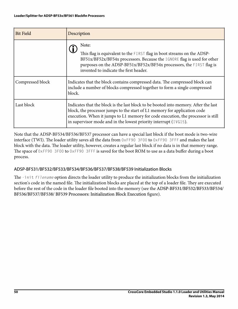
Bit Field Description
iNote:
This flag is equivalent to the FIRST flag in boot streams on the ADSP-BF51x/BF52x/BF54x processors. Because the IGNORE flag is used for otherpurposes on the ADSP-BF51x/BF52x/BF54x processors, the FIRST flag isinvented to indicate the first header.
Compressed block Indicates that the block contains compressed data. The compressed block caninclude a number of blocks compressed together to form a single compressedblock.
Last block Indicates that the block is the last block to be booted into memory. After the lastblock, the processor jumps to the start of L1 memory for application codeexecution. When it jumps to L1 memory for code execution, the processor is stillin supervisor mode and in the lowest priority interrupt (IVG15).
Note that the ADSP-BF534/BF536/BF537 processor can have a special last block if the boot mode is two-wireinterface (TWI). The loader utility saves all the data from 0xFF90 3F00 to 0xFF90 3FFF and makes the lastblock with the data. The loader utility, however, creates a regular last block if no data is in that memory range.The space of 0xFF90 3F00 to 0xFF90 3FFF is saved for the boot ROM to use as a data buffer during a bootprocess.
ADSP-BF531/BF532/BF533/BF534/BF536/BF537/BF538/BF539 Initialization Blocks
The -init filename option directs the loader utility to produce the initialization blocks from the initializationsection's code in the named file. The initialization blocks are placed at the top of a loader file. They are executedbefore the rest of the code in the loader file booted into the memory (see the ADSP-BF531/BF532/BF533/BF534/BF536/BF537/BF538/ BF539 Processors: Initialization Block Execution figure).
Loader/Splitter for ADSP-BF53x/BF561 Blackfin Processors
50 CrossCore Embedded Studio 1.1.0 Loader and Utilities ManualRevision 1.3, May 2014

INIT BLOCK HEADER
APP.CODE/DATA
INIT BLOCKS
L1 BLOCK HEADER
L1 BLOCK
SDRAM BLOCK HEADER
BLOCK N
........
BLOCK N 10-BYTE HEADER
SDRAM BLOCK
ADSP-BF531/32/33/34/36/37/39/39 ProcessorPROM/FLASH OR SPI DEVICE
L1 MemoryInit Blocks
SDRAM
0xEF00 0000
On-ChipBoot ROM
Figure 6. ADSP-BF531/BF532/BF533/BF534/BF536/BF537/BF538/ BF539 Processors: Initialization BlockExecution
Following execution of the initialization blocks, the boot process continues with the rest of data blocks until itencounters a final block (see the ADSP-BF531/BF532/BF533/BF534/BF536/BF537/BF538/ BF539 Processors:Booting Application Code figure). The initialization code example follows in Initialization Block Code Example.
ADSP-BF531/BF532/BF533/BF534/BF536/BF537/BF538/ BF539 Processors: Booting Application Code
A
L1 Me mor yInit Block
SDRAM
0x EF00 0 000
On-Ch pBootROM
i
L1 Block
SDRAM Block
INIT BLOCK HEADER
APP.CODE/DATA
INIT BLOCKS
L1 BLOCK HEADER
L1 BLOCK
SDRAM BLOCK HEADER
BLOCK N
........
BLOCK N 10-BYTE HEADER
SDRAM BLOCK
PROM/FLASH OR SPI DEVICE
ADSP-BF531/32/33/34/36/37/39/39 Processor
Initialization Block Code Example
/* This file contains 3 sections: */
/* 1) A Pre-Init Section-this section saves off all the
processor registers onto the stack.
2) An Init Code Section-this section is the initialization
code which can be modified by the customer
Loader/Splitter for ADSP-BF53x/BF561 Blackfin Processors
CrossCore Embedded Studio 1.1.0 Loader and Utilities ManualRevision 1.3, May 2014
51

As an example, an SDRAM initialization code is supplied.
The example setups the SDRAM controller as required by
certain SDRAM types. Different SDRAMs may require
different initialization procedure or values.
3) A Post-Init Section-this section restores all the register
from the stack. Customers should not modify the Pre-Init
and Post-Init Sections. The Init Code Section can be
modified for a particular application.*/
#include <defBF532.h>
.SECTION program;
/**********************Pre-Init Section************************/
[--SP] = ASTAT; /* Stack Pointer (SP) is set to the end of */
[--SP] = RETS; /* scratchpad memory (0xFFB00FFC) */
[--SP] = (r7:0); /* by the on-chip boot ROM */
[--SP] = (p5:0);
[--SP] = I0;[--SP] = I1;[--SP] = I2;[--SP] = I3;
[--SP] = B0;[--SP] = B1;[--SP] = B2;[--SP] = B3;
[--SP] = M0;[--SP] = M1;[--SP] = M2;[--SP] = M3;
[--SP] = L0;[--SP] = L1;[--SP] = L2;[--SP] = L3;
/*******************Init Code Section**************************/
/*******Please insert Initialization code in this section******/
/***********************SDRAM Setup****************************/
Setup_SDRAM:
P0.L = LO(EBIU_SDRRC);
/* SDRAM Refresh Rate Control Register */
P0.H = HI(EBIU_SDRRC);
R0 = 0x074A(Z);
W[P0] = R0;
SSYNC;
Loader/Splitter for ADSP-BF53x/BF561 Blackfin Processors
52 CrossCore Embedded Studio 1.1.0 Loader and Utilities ManualRevision 1.3, May 2014

P0.L = LO(EBIU_SDBCTL);
/* SDRAM Memory Bank Control Register */
P0.H = HI(EBIU_SDBCTL);
R0 = 0x0001(Z);
W[P0] = R0;
SSYNC;
P0.L = LO(EBIU_SDGCTL);
/* SDRAM Memory Global Control Register */
P0.H = HI(EBIU_SDGCTL);
R0.L = 0x998D;
R0.H = 0x0091;
[P0] = R0;
SSYNC;
/*********************Post-Init Section************************/
L3 = [SP++]; L2 = [SP++]; L1 = [SP++]; L0 = [SP++];
M3 = [SP++]; M2 = [SP++]; M1 = [SP++]; M0 = [SP++];
B3 = [SP++]; B2 = [SP++]; B1 = [SP++]; B0 = [SP++];
I3 = [SP++]; I2 = [SP++]; I1 = [SP++]; I0 = [SP++];
(p5:0) = [SP++];
(r7:0) = [SP++];
RETS = [SP++];
ASTAT = [SP++];
/************************************************************/
RTS;
ADSP-BF531/BF532/BF533/BF534/BF536/BF537/BF538/BF539 Processor No-Boot ModeThe hardware settings of BMODE = 00 for the ADSP-BF531, ADSP-BF532, and ADSP-BF533 processors selectthe no-boot option. In this mode of operation, the on-chip boot kernel is bypassed after reset, and the processorstarts fetching and executing instructions from address 0x2000 0000 in the asynchronous memory bank 0. Theprocessor assumes 16-bit memory with valid instructions at that location.
To create a proper .ldr file that can be burned into either a parallel flash or EPROM device, you must modifythe standard LDF file in order for the reset vector to be located accordingly. The Section Assignment (LDF File)
Loader/Splitter for ADSP-BF53x/BF561 Blackfin Processors
CrossCore Embedded Studio 1.1.0 Loader and Utilities ManualRevision 1.3, May 2014
53

Example and ROM Segment Definitions (LDF File) Example code fragments illustrate the requiredmodifications in case of an ADSP-BF533 processor.
Section Assignment (LDF File) Example
MEMORY
{
/* Off-chip Instruction ROM in Async Bank 0 */
MEM_PROGRAM_ROM { TYPE(ROM) START(0x20000000) END(0x2009FFFF) WIDTH(8) }
/* Off-chip constant data in Async Bank 0 */
MEM_DATA_ROM { TYPE(ROM) START(0x200A0000) END(0x200FFFFF) WIDTH(8) }
/* On-chip SRAM data, is not booted automatically */
MEM_DATA_RAM { TYPE(RAM) START(0xFF903000) END(0xFF907FFF) WIDTH(8) }
ROM Segment Definitions (LDF File) Example
PROCESSOR p0
{
OUTPUT( $COMMAND_LINE_OUTPUT_FILE )
SECTIONS
{
program_rom
{
INPUT_SECTION_ALIGN(4)
INPUT_SECTIONS( $OBJECTS(rom_code) )
} >MEM_PROGRAM_ROM
data_rom
{
INPUT_SECTION_ALIGN(4)
INPUT_SECTIONS( $OBJECTS(rom_data) )
} >MEM_DATA_ROM
data_sram
{
INPUT_SECTION_ALIGN(4)
INPUT_SECTIONS( $OBJECTS(ram_data) )
Loader/Splitter for ADSP-BF53x/BF561 Blackfin Processors
54 CrossCore Embedded Studio 1.1.0 Loader and Utilities ManualRevision 1.3, May 2014

} >MEM_DATA_RAM
With the LDF file modified this way, the source files can now take advantage of the newly-introduced sections, asin Section Handling (Source File) Example.
Section Handling (Source File) Example
.SECTION rom_code;
_reset_vector: l0 = 0;
1 = 0;
l2 = 0;
l3 = 0;
/* continue with setup and application code */
/* . . . */
.SECTION rom_data;
.VAR myconst x = 0xdeadbeef;
/* . . . */
.SECTION ram_data;
.VAR myvar y; /* note that y cannot be initialized automatically */
ADSP-BF531/BF532/BF533/BF534/BF536/BF537/BF538/BF539 Processor Memory RangesThe on-chip boot ROM on the ADSP-BF531/BF532/BF533/BF534/BF536/ BF537/BF538/BF539 Blackfinprocessors allows booting to the following memory ranges.
• L1 memory
• ADSP-BF531 processor:
Data bank A SRAM (0xFF80 4000-0xFF80 7FFF)
Instruction SRAM (0xFFA0 8000-0xFFA0 BFFF)• ADSP-BF532 processor:
Data bank A SRAM (0xFF80 4000-0xFF80 7FFF)
Data bank B SRAM (0xFF90 4000-0xFF90 7FFF)
Instruction SRAM (0xFFA0 8000-0xFFA1 3FFF)• ADSP-BF533 processor:
Data bank A SRAM (0xFF80 0000-0xFF80 7FFF)
Data bank B SRAM (0xFF90 000-0xFF90 7FFF)
Instruction SRAM (0xFFA0 0000-0xFFA1 3FFF)• ADSP-BF534 processor:
Loader/Splitter for ADSP-BF53x/BF561 Blackfin Processors
CrossCore Embedded Studio 1.1.0 Loader and Utilities ManualRevision 1.3, May 2014
55

Data bank A SRAM (0xFF80 0000-0xFF80 7FFF)
Data bank B SRAM (0xFF90 0000-0xFF90 7FFF)
Instruction SRAM (0xFFA0 0000-0xFFA1 3FFF)• ADSP-BF536 processor:
Data bank A SRAM (0xFF80 4000-0xFF80 7FFF)
Data bank B SRAM (0xFF90 4000-0xFF90 7FFF)
Instruction SRAM (0xFFA0 0000-0xFFA1 3FFF)• ADSP-BF537 processor:
Data bank A SRAM (0xFF80 0000-0xFF80 7FFF)
Data bank B SRAM (0xFF90 0000-0xFF90 7FFF)
Instruction SRAM (0xFFA0 0000-0xFFA1 3FFF)• ADSP-BF538 processor:
Data bank A SRAM (0xFF80 4000-0xFF80 7FFF)
Data bank B SRAM (0xFF90 4000-0xFF90 7FFF)
Instruction SRAM (0xFFA0 8000-0xFFA1 3FFF)• ADSP-BF539 processor:
Data bank A SRAM (0xFF80 0000-0xFF80 3FFF)
Data bank B SRAM (0xFF90 2000-0xFF90 7FFF)
Instruction SRAM (0xFFA0 0000-0xFFA1 3FFF)• SDRAM memory:
• Bank 0 (0x0000 0000-0x07FF FFFF)
iNote:
Booting to scratchpad memory (0xFFB0 0000) is not supported.
iNote:
SDRAM must be initialized by user code before any instructions or data are loaded into it.
ADSP-BF561 Processor BootingThe booting sequence for the ADSP-BF561 dual-core processors is similar to the ADSP-BF531/BF532/BF533processor boot sequence described in ADSP-BF531/BF532/BF533/BF534/BF536/BF537/BF538/BF539 ProcessorOn-Chip Boot ROM. Differences occur because the ADSP-BF561 processor has two cores: core A and core B.After reset, core B remains idle, but core A executes the on-chip boot ROM located at address 0xEF00 0000.
The ADSP-BF561 ROM details can be found in ADSP-BF561 Processor On-Chip Boot ROM.
Loader/Splitter for ADSP-BF53x/BF561 Blackfin Processors
56 CrossCore Embedded Studio 1.1.0 Loader and Utilities ManualRevision 1.3, May 2014

The ADSP-BF561 Processor Boot Mode Selections table summarizes the boot modes and execution startaddresses for the ADSP-BF561 processors.
Table 12. ADSP-BF561 Processor Boot Mode Selections
Boot Source BMODE[1:0]
16-bit external memory (bypass boot ROM) 00
8- or 16-bit flash 01
SPI host 10
SPI serial EEPROM (16-bit address range) 11
• Execute from 16-bit external memory - execution starts from address 0x2000 0000 with 16-bit packing. Theboot ROM is bypassed in this mode. All configuration settings are set for the slowest device possible (3-cyclehold time, 15-cycle R/W access times, 4-cycle setup).
• Boot from 8-bit/16-bit external flash memory - the 8-bit/16-bit flash boot routine located in boot ROMmemory space is set up using asynchronous memory bank 0. All configuration settings are set for the slowestdevice possible (3-cycle hold time; 15-cycle R/W access times; 4-cycle setup).
• Boot from SPI host - the ADSP-BF561 processor is configured as an SPI slave device and a host is used to bootthe processor. The host drives the SPI clock and is therefore responsible for the timing. The baud rate should beequal to or less than one fourth of the ADSP-BF561 system clock (SCLK).
• Boot from SPI serial EEPROM (16-bit addressable) - the SPI uses the PF2 output pin to select a single SPIEPROM device, submits a read command at address 0x0000, and begins clocking data into the beginning of L1instruction memory. A 16-bit/24-bit addressable SPI-compatible EPROM must be used.
The following loader topics also are discussed in this chapter.
• ADSP-BF561 Processor Boot Streams• ADSP-BF561 Processor Initialization Blocks• ADSP-BF561 Dual-Core Application Management• ADSP-BF561 Processor Memory Ranges
iNote:
Refer to the ADSP-BF561 Embedded Symmetric Multiprocessor data sheet and the ADSP-BF561 BlackfinProcessor Hardware Reference manual for information about the processor’s operating modes and states,including background information on system reset and booting.
ADSP-BF561 Processor On-Chip Boot ROMThe boot ROM loads an application program from an external memory device and starts executing thatprogram by jumping to the start of core A's L1 instruction SRAM, at address 0xFFA0 0000.
Loader/Splitter for ADSP-BF53x/BF561 Blackfin Processors
CrossCore Embedded Studio 1.1.0 Loader and Utilities ManualRevision 1.3, May 2014
57

Similar to the ADSP-BF531/BF532/BF533 processor, the ADSP-BF561 boot ROM uses the interrupt vectors tostay in supervisor mode.
The boot ROM code transitions from the RESET interrupt service routine into the lowest priority user interruptservice routine (Int 15) and remains in the interrupt service routine. The boot ROM then checks whether it hasbeen invoked by a software reset by examining bit 4 of the system reset configuration register (SYSCR).
If bit 4 is not set, the boot ROM presumes that a hard reset has occurred and performs the full boot sequence. Ifbit 4 is set, the boot ROM understands that the user code has invoked a software reset and restarts the userprogram by jumping to the beginning of core A's L1 memory (0xFFA0 0000), bypassing the entire bootsequence.
When developing an ADSP-BF561 processor application, you start with compiling and linking your applicationcode into an executable (.dxe) file. The debugger loads the .dxe file into the processor's memory and executesit. With two cores, two .dxe files can be loaded at once. In the real-time environment, there is no debuggerwhich allows the boot ROM to load the executables into memory.
ADSP-BF561 Processor Boot StreamsThe loader utility converts the .dxe file into a boot stream (.ldr) file by parsing the executable and creating blocks. Each block is encapsulated within a 10-byte header. The .ldr file is burned into the external memorydevice (flash memory, PROM, or EEPROM). The boot ROM reads the external memory device, parsing theheaders and copying the blocks to the addresses where they reside during program execution. After all the blocksare loaded, the boot ROM jumps to address 0xFFA0 0000 to execute the core A program.
iNote:
When code is run on both cores, the core A program is responsible for releasing core B from the idle stateby clearing bit 5 in core A’s system configuration register. Then core B begins execution at address 0xFF600000.
Multiple .dxe files are often combined into a single boot stream (see ADSP-BF561 Dual-Core ApplicationManagement and ADSP-BF53x and ADSP-BF561 Multi-Application (Multi-DXE) Management).
Unlike the ADSP-BF531/BF532/BF533 processor, the ADSP-BF561 boot stream begins with a 4-byte globalheader, which contains information about the external memory device. A bit-by-bit description of the globalheader is presented in the ADSP-BF561 Global Header Structure table. The global header also contains asignature in the upper 4 bits that prevents the boot ROM from reading in a boot stream from a blank device.
Table 13. ADSP-BF561 Global Header Structure
Bit Field Description
0 1 = 16-bit flash, 0 = 8-bit flash; default is 0
1-4 Number of wait states; default is 15
Loader/Splitter for ADSP-BF53x/BF561 Blackfin Processors
58 CrossCore Embedded Studio 1.1.0 Loader and Utilities ManualRevision 1.3, May 2014

Bit Field Description
5 Unused bit
6-7 Number of hold time cycles for flash; default is 3
8-10 Baud rate for SPI boot: 00 = 500k, 01 = 1M, 10 = 2M
11-27 Reserved for future use
28-31 Signature that indicates valid boot stream
Following the global header is a .dxecount block, which contains a 32-bit byte count for the first .dxe file in theboot stream. Though this block contains only a byte count, it is encapsulated by a 10-byte block header, just likethe other blocks.
The 10-byte header instructs the boot ROM where, in memory, to place each block, how many bytes to copy, andwhether the block needs any special processing. The block header structure is the same as that of the ADSP-BF531/BF532/BF533 processors (described in ADSP-BF531/BF532/BF533/BF534/BF536/BF537/BF538/ BF539Block Headers and Flags).). Each header contains a 4-byte start address for the data block, a 4-byte count for thedata block, and a 2-byte flag word, indicating whether the data block is a "zero-fill" block or a "final block" (thelast block in the boot stream).
For the .dxe count block, the address field is irrelevant since the block is not going to be copied to memory. The"ignore bit" is set in the flag word of this header, so the boot loader utility does not try to load the .dxe count butskips the count. For more details, see ADSP-BF531/BF532/BF533/BF534/BF536/BF537/BF538/ BF539 BlockHeaders and Flags.
Following the .dxe count block are the rest of the blocks of the first .dxe.
A bit-by-bit description of the boot steam is presented in the ADSP-BF561 Processor Boot Stream Structuretable. When learning about the ADSP-BF561 boot stream structure, keep in mind that the count byte foreach .dxe is, itself, a block encapsulated by a block header.
Table 14. ADSP-BF561 Processor Boot Stream Structure
Bit Field Description
0-7 LSB of the global header 32-Bit GlobalHeader
8-15 8-15 of the global header
16-23 16-23 of the global header
Loader/Splitter for ADSP-BF53x/BF561 Blackfin Processors
CrossCore Embedded Studio 1.1.0 Loader and Utilities ManualRevision 1.3, May 2014
59

Bit Field Description
24-31 MSB of the global header
32-39 LSB of the address field of 1st .dxe countblock (no care)
10-Byte .dxe1Header
40-47 8-15 of the address field of 1st .dxe countblock (no care)
48-55 16-23 of the address field of 1st .dxe countblock (no care)
56-63 MSB of the address field of 1st .dxe countblock (no care)
64-71 LSB (4) of the byte count field of 1st .dxecount block
72-79 8-15 (0) of the byte count field of 1st .dxecount block
80-87 16-23 (0) of the byte count field of 1st .dxecount block
88-95 MSB (0) of the byte count field of 1st .dxecount block
96-103 LSB of the flag word of 1st .dxe countblock - ignore bit set
104-111 MSB of the flag word of 1st .dxe countblock
112-119 LSB of the first 1st .dxe byte count 32-Bit Block ByteCount
120-127 8-15 of the first 1st .dxe byte count
128-135 16-23 of the first 1st .dxe byte count
136-143 24-31 of the first 1st .dxe byte count
Loader/Splitter for ADSP-BF53x/BF561 Blackfin Processors
60 CrossCore Embedded Studio 1.1.0 Loader and Utilities ManualRevision 1.3, May 2014

Bit Field Description
1-0-Byte BlockHeader
144-151 LSB of the address field of the 1st datablock in 1st .dxe
.dxe1 Block Data
152-159 8-15 of the address field of the 1st datablock in 1st .dxe
160-167 16-23 of the address field of the 1st datablock in 1st .dxe
168-175 MSB of the address field of the 1st datablock in 1st .dxe
176-183 LSB of the byte count of the 1st data blockin 1st .dxe
184-191 8-15 of the byte count of the 1st data blockin 1st .dxe
192-199 16-23 of the byte count of the 1st data blockin 1st .dxe
200-207 MSB of the byte count of the 1st data blockin 1st .dxe
208-215 LSB of the flag word of the 1st block in1st .dxe
216-223 MSB of the flag word of the 1st block in1st .dxe
Block Data 224-231 Byte 3 of the 1st block of 1st .dxe
232-239 Byte 2 of the 1st block of 1st .dxe
240-247 Byte 1 of the 1st block of 1st .dxe
248-255 Byte 0 of the 1st block of 1st .dxe
256-263 Byte 7 of the 1st block of 1st .dxe
Loader/Splitter for ADSP-BF53x/BF561 Blackfin Processors
CrossCore Embedded Studio 1.1.0 Loader and Utilities ManualRevision 1.3, May 2014
61

Bit Field Description
... And so on ...
10-Byte BlockHeader
... LSB of the address field of the nth datablock in 1st .dxe
... 8-15 of the address field of the nth datablock in 1st .dxe
... 16-23 of the address field of the nth datablock in 1st .dxe
... MSB of the address field of the nth datablock in 1st .dxe
... LSB of the byte count of the nth data blockin 1st .dxe
... 8-15 of the byte count of the nth data blockin 1st .dxe
... 16-23 of the byte count of the nth datablock in 1st .dxe
... MSB of the byte count of the nth data blockin 1st .dxe
... LSB of the flag word of the nth block in1st .dxe
... MSB of the flag word of the nth block in1st .dxe
Block data ... And so on ...
... Byte 1 of the nth block of 1st .dxe
... Byte 0 of the nth block of 1st .dxe
... LSB of the address field of 2nd .dxe countblock (no care)
10-Byte .dxe2Header
Loader/Splitter for ADSP-BF53x/BF561 Blackfin Processors
62 CrossCore Embedded Studio 1.1.0 Loader and Utilities ManualRevision 1.3, May 2014

Bit Field Description
... 8-15 of the address field of 2nd .dxe countblock (no care)
... And so on ...
ADSP-BF561 Processor Initialization BlocksThe initialization block or a second-stage loader utility must be used to initialize the SDRAM memory of theADSP-BF561 processor before any instructions or data are loaded into it.
The initialization blocks are identified by a bit in the flag word of the 10-byte block header. When the boot ROMencounters the initialization blocks in the boot stream, it loads the blocks and executes them immediately. Theinitialization blocks must save and restore registers and return to the boot ROM, so the boot ROM can load therest of the blocks. For more details, see ADSP-BF531/BF532/BF533/BF534/BF536/BF537/BF538/ BF539 BlockHeaders and Flags.
Both the initialization block and second-stage loader utility can be used to force the boot ROM to load aspecific .dxe file from the external memory device if the boot ROM stores multiple executable files. Theinitialization block can manipulate the R0 or R3 register, which the boot ROM uses as the external memorypointers for flash/PROM or SPI memory boot, respectively.
After the processor returns from the execution of the initialization blocks, the boot ROM continues to loadblocks from the location specified in the R0 or R3 register, which can be any .dxe file in the boot stream. Thisoption requires the starting locations of specific executables within external memory. The R0 or R3 register mustpoint to the 10-byte count header, as illustrated in ADSP-BF53x and ADSP-BF561 Multi-Application (Multi-DXE) Management.
ADSP-BF561 Dual-Core Application ManagementA typical ADSP-BF561 dual-core application is separated into two executable files: one executable file for eachcore. The default linker description (.ldf) file for the ADSP-BF561 processor creates two separate executablefiles (p0.dxe and p1.dxe) and some shared memory files (sml2.sm and sml3.sm). By modifying the LDF, it ispossible to create a dual-core application that combines both cores into a single .dxe file. This is notrecommended unless the application is a simple assembly language program which does not link any C run-timelibraries. When using shared memory and/or C run-time routines on both cores, it is best to generate aseparate .dxe file for each core. The loader utility combines the contents of the shared memory files (sml2.sm,sml3.sm) only into the boot stream generated from the .dxe file for core A (p0.dxe).
By default, the boot ROM loads only one single executable before the ROM jumps to the start of core A instruction SRAM (0xFFA0 0000). When two .dxe files are loaded, a second-stage loader is used. (Or, when the-noSecondStageKernel switch is called, the loader utility combines the two .dxe files into one.) If the hesecond-stage boot loader is used, it must start at 0xFFA0 0000. The boot ROM loads and executes the second-stage loader. A default second-stage loader is provided for each boot mode and can be customized by the user.
Loader/Splitter for ADSP-BF53x/BF561 Blackfin Processors
CrossCore Embedded Studio 1.1.0 Loader and Utilities ManualRevision 1.3, May 2014
63

Unlike the initialization blocks, the second-stage loader takes full control over the boot process and neverreturns to the boot ROM.
The second-stage loader can use the .dxe byte count blocks to find specific .dxe files in external memory if aloader file includes the codes and data from a number of .dxe files.
xAttention:
The default second-stage loader uses the last 1024 bytes of L2 memory. The area must be reserved duringbooting but can be reallocated at runtime.
ADSP-BF561 Processor Memory RangesThe on-chip boot ROM of the ADSP-BF561 processor can load a full application to the various memories ofboth cores. Booting is allowed to the following memory ranges. The boot ROM clears these memory rangesbefore booting in a new application.
• Core A
• L1 instruction SRAM (0xFFA0 0000 - 0xFFA0 3FFF)• L1 instruction cache/SRAM (0xFFA1 0000 - 0xFFA1 3FFF)• L1 data bank A SRAM (0xFF80 0000 - 0xFF80 3FFF)• L1 data bank A cache/SRAM (0xFF80 4000 - 0xFF80 7FFF)• L1 data bank B SRAM (0xFF90 0000 - 0xFF90 3FFF)• L1 data bank B cache/SRAM (0xFF90 4000 - 0xFF90 7FFF)
• Core B
• L1 instruction SRAM (0xFF60 0000 - 0xFF6 03FFF)• L1 instruction cache/SRAM (0xFF61 0000 - 0xFF61 3FFF)• L1 data bank A SRAM (0xFF40 0000 - 0xFF40 3FFF)• L1 data bank A cache/SRAM (0xFF40 4000 - 0xFF40 7FFF)• L1 data bank B SRAM (0xFF50 0000 - 0xFF50 3FFF)• L1 data bank B cache/SRAM (0xFF50 4000 - 0xFF50 7FFF)
• 128K of shared L2 memory (FEB0 0000 - FEB1 FFFF)• Four banks of configurable synchronous DRAM (0x0000 0000 - (up to) 0x1FFF FFFF)
xAttention:
The boot ROM does not support booting to core A scratch memory (0xFFB0 0000 - 0xFFB0 0FFF) andto core B scratch memory (0xFF70 0000-0xFF70 0FFF). Data that needs to be initialized prior toruntime should not be placed in scratch memory.
ADSP-BF53x and ADSP-BF561 Multi-Application (Multi-DXE) ManagementThis section describes how to generate and boot more than one .dxe file for the ADSP-BF531/BF532/BF533/BF534/BF536/BF537/ BF538/BF539 and ADSP-BF561 processors. For further information about the ADSP-BF561 processors, refer to ADSP-BF561 Dual-Core Application Management.
Loader/Splitter for ADSP-BF53x/BF561 Blackfin Processors
64 CrossCore Embedded Studio 1.1.0 Loader and Utilities ManualRevision 1.3, May 2014

The ADSP-BF531/BF532/BF533/BF534/ BF536/BF537/BF538/BF539 and ADSP-BF561 loader file structure andthe silicon revision of 0.1 and higher allow generation and booting of multiple .dxe files into a single processorfrom external memory. As illustrated in the ADSP-BF531/BF32/BF33/BF534/ BF536/BF537/BF538/ BF539/BF561 Processors: Multi-Application Booting Streams figure, each executable file is preceded by a 4-byte countheader, which is the number of bytes within the executable, including headers. This information can be used toboot a specific .dxe file into the processor. The 4-byte .dxe count block is encapsulated within a 10-byte headerto be compatible with the silicon revision 0.0. For more information, see ADSP-BF531/BF532/BF533/BF534/BF536/BF537/BF538/ BF539 Block Headers and Flags.
BLOCK 1
BLOCK 2 10-BYTE HEADER
BLOCK 3 10-BYTE HEADER
BLOCK 2
BLOCK 1 10-BYTE HEADER10-BYTE HEADER FOR COUNT
4-BYTE COUNT FOR .DXE1
.DXE 1 APPLICATION
10-BYTE HEADER FOR COUNT
4-BYTE COUNT FOR .DXE 2
.DXE 2 APPLICATION
10-BYTE HEADER FOR COUNT
4-BYTE COUNT FOR .DXE 3
.DXE 3 APPLICATION
10-BYTE HEADER FOR COUNT
4-BYTE COUNT FOR .DXE 4
.......................
.......................
.DXE 1
.DXE 2
.DXE 3
.DXE 4
BLOCK 3
..............
Figure 7. ADSP-BF531/BF32/BF33/BF534/ BF536/BF537/BF538/ BF539/BF561 Processors: Multi-ApplicationBooting Streams
Booting multiple executables can be accomplished by one of the following methods.
• Use the second-stage loader switch, -l userkernel.dxe. The option allows you to use your own second-stageloader.
After the second-stage loader is booted into internal memory via the on-chip boot ROM, the loader has fullcontrol over the boot process. Now the second-stage loader can use the .dxe byte counts to boot in one ormore .dxe files from external memory.
• Use the initialization block switch, -init filename.dxe, where filename.dxe is the name of the executablefile containing the initialization code. This option allows you to change the external memory pointer and boot
Loader/Splitter for ADSP-BF53x/BF561 Blackfin Processors
CrossCore Embedded Studio 1.1.0 Loader and Utilities ManualRevision 1.3, May 2014
65

a specific .dxe file via the on-chip boot ROM. On the ADSP-BF531 and ADSP-BF561 processors, theinitialization code is an assembly written subroutine.
A sample initialization code is included in Listing 3-5. The R0 and R3 registers are used as external memorypointers by the on-chip boot ROM. The R0 register is for flash/PROM boot, and R3 is for SPI memory boot.Within the initialization block code, change the value of R0 or R3 to point to the external memory location atwhich the specific application code starts. After the processor returns from the initialization block code to theon-chip boot ROM, the on-chip boot ROM continues to boot in bytes from the location specified in the R0 or R3register.
Initialization Block Code Example for Multiple .dxe Boot
#include <defBF532.h>
.SECTION program;
/*******Pre-Init Section***************************************/
[--SP] = ASTAT;
[--SP] = RETS;
[--SP] = (r7:0);
[--SP] = (p5:0);
[--SP] = I0;[--SP] = I1;[--SP] = I2;[--SP] = I3;
[--SP] = B0;[--SP] = B1;[--SP] = B2;[--SP] = B3;
[--SP] = M0;[--SP] = M1;[--SP] = M2;[--SP] = M3;
[--SP] = L0;[--SP] = L1;[--SP] = L2;[--SP] = L3;
/**************************************************************/
/*******Init Code Section**************************************
R0.H = High Address of DXE Location (R0 for flash/PROM boot, R3 for SPI boot)
R0.L = Low Address of DXE Location. (R0 for flash/PROM boot, R3 for SPI boot)
***************************************************************/
/*******Post-Init Section**************************************/
L3 = [SP++]; L2 = [SP++]; L1 = [SP++]; L0 = [SP++];
M3 = [SP++]; M2 = [SP++]; M1 = [SP++]; M0 = [SP++];
B3 = [SP++]; B2 = [SP++]; B1 = [SP++]; B0 = [SP++];
I3 = [SP++]; I2 = [SP++]; I1 = [SP++]; I0 = [SP++];
(p5:0) = [SP++];
/* MAKE SURE NOT TO RESTORE R0 for flash/PROM Boot, R3 for SPI Boot */
(r7:0) = [SP++];
RETS = [SP++];
Loader/Splitter for ADSP-BF53x/BF561 Blackfin Processors
66 CrossCore Embedded Studio 1.1.0 Loader and Utilities ManualRevision 1.3, May 2014

ASTAT = [SP++];
/**************************************************************/
RTS;
ADSP-BF531/BF532/BF533/BF534/BF536/BF537 Processor Compression SupportThe loader utility for the ADSP-BF531/BF532/BF533/BF534/BF536/BF537 processors offers a loader file (bootstream) compression mechanism known as zLib. The zLib compression is supported by a third party dynamiclink library, zLib1.dll. Additional information about the library can be obtained from the http://www.zlib.netWeb site.
The zLib1.dll dynamic link library is included with CrossCore Embedded Studio. The library functionsperform the boot stream compression and decompression procedures when the appropriate options are selectedfor the loader utility. The initialization executable files with built-in decompression mechanism must performthe decompression on a compressed boot stream in a boot process. The default initialization executable files withdecompression functions are included in CrossCore Embedded Studio.
The loader -compression switch directs the loader utility to perform the boot stream compression from thecommand line. The IDE also includes a dedicated loader properties page to manage the compression. Refer tothe online help for details.
The loader utility takes two steps to compress a boot stream. First, the utility generates the boot stream in theconventional way (builds data blocks), then applies the compression to the boot stream. The decompressioninitialization is the reversed process: the loader utility decompresses the compressed stream first, then loads codeand data into memory segments in the conventional way.
The loader utility compresses the boot stream on the .dxe-by-.dxe basis. For each input .dxe file, the utilitycompresses the code and data together, including all code and data from any associated overlay (.ovl) andshared memory (.sm) files.
Compressed StreamsThe Loader File with Compressed Streams figure illustrates the basic structure of a loader file with compressed streams.
Loader/Splitter for ADSP-BF53x/BF561 Blackfin Processors
CrossCore Embedded Studio 1.1.0 Loader and Utilities ManualRevision 1.3, May 2014
67

INITIALIZATION CODE (KERNEL WITH DECOMPRESSION ENGINE)
......
1st .dxe COMPRESSED STREAM
1st .dxe UNCOMPRESSED STREAM
2nd .dxe COMPRESSED STREAM
2nd .dxe UNCOMPRESSED STREAM
......
Figure 8. Loader File with Compressed Streams
The initialization code is on the top of the loader file. The initialization code is loaded into the processor first andis executed first when a boot process starts. Once the initialization code is executed, the rest of the stream isbrought into the processor. The initialization code calls the decompression routine to perform thedecompression operation on the stream, and then loads the decompressed stream into the processor's memoryin the same manner a conventional boot kernel does when it encounters a compressed stream. Finally, the loaderutility loads the uncompressed boot stream in the conventional way.
The Compressed Block figure illustrates the structure of a compressed block.
COMPRESSED BLOCK HEADER
COMPRESSED STREAM
Figure 9. Compressed Block
Compressed Block HeadersA compressed stream always has a header, followed by the payload compressed stream. The Compressed BlockHeader figure shows the structure of a compressed block header.
16 BITS: PADDED BYTE COUNTOF COMPRESSED STREAM
32 BITS:TOTAL BYTE COUNT OF THE COMPRESSED STREAM
INCLUDING PADDED BYTES
16 BITS:COMPRESSED BLOCK FLAG WORD
16 BITS: SIZE OF USED COMPRESSION WINDOW
Figure 10. Compressed Block Header
Loader/Splitter for ADSP-BF53x/BF561 Blackfin Processors
68 CrossCore Embedded Studio 1.1.0 Loader and Utilities ManualRevision 1.3, May 2014

The first 16 bits of the compressed block header hold the padded byte count of the compressed stream. Theloader utility always pads the byte count if the resulting compressed stream from the loader compression engineis an odd number. The loader utility rounds up the byte count of the compressed stream to be a next higher evennumber. This 16-bit value is either 0x0000 or 0x0001.
The second 16 bits of the compressed block header hold the size of the compression window, used by the loadercompression engine. The value range is 8-15 bits, with the default value of 9 bits. The compression window sizespecifies to the compression engine a number of bytes taken from the window during the compression. Thewindow size is the 2's exponential value.
As mentioned before, the compression/decompression mechanism for Blackfin processors utilizes the open-source lossless data-compression library zLib1. The zLib1 deflate algorithm, in turn, is a combination of avariation of Huffman coding and LZ77 compression algorithms.
LZ77 compression works by finding sequences of data that are repeated within a sliding window. As expected,with a larger sliding window, the compression algorithm is able to find more repeating sequences of data,resulting in higher compression ratios. However, technical limitations of the zLib1 decompression algorithmdictate that the window size of the decompressor must be the same as the window size of the compressor. For amore detailed technical explanation of the compression/decompression implementation on a Blackfin processor,refer to the readme.txt file in the <install_path>/Blackfin/ldr/zlib/src directory.
iNote:
It is not recommended to use memory ranges used by the zlib kernel. The memory ranges used by thekernel, such as heap and static data, are defined in the LDF file, for example in <install_- path>/Blackfin/ldr/zlib/src/blkfin_zlib_init.ldf.
In the Blackfin implementation, the decompressor is part of the decompression initialization files (see Decompression Initialization Files). These files are built with a default decompressor window size of 9 bits (512bytes). Thus, if you choose a non-default window size for the compressor from the Compression window size (-compressWS) drop-down list on the loader's Compression properties page, then the decompressor must be re-built with the new window size. Refer to the CCES online help for information about the Compressionproperties page. For details on re-building of the decompressor init project, refer to the readme.txt file locatedin the <install_path>/Blackfin/ldr/zlib/src directory.
While it is true that a larger compression window size results in better compression ratios, note that there arecounter factors that decrease the overall effective compression ratios with increasing window sizes for Blackfin'simplementation of zlib. This is because of the limited memory resources on an embedded target, such as aBlackfin processor. For more information, refer to the readme.txt file in the <install_path>/Blackfin/ldr/zlib/src directory.
The last 16 bits of the compressed header is the flag word. The valid compression flag assignments are shown inthe Flag Word of Compressed Block Header figure.
Loader/Splitter for ADSP-BF53x/BF561 Blackfin Processors
CrossCore Embedded Studio 1.1.0 Loader and Utilities ManualRevision 1.3, May 2014
69

0
03151
Compression Flag:Bit 13: 0 = Not Compression Mode 1 = Compression Block
1
Figure 11. Flag Word of Compressed Block Header
Uncompressed StreamsFollowing the compressed streams (illustrated in the Loader File with Compressed Streams figure in Compressed Streams), the loader file includes the uncompressed streams. The uncompressed streams includeapplication codes, conflicted with the code in the initialization blocks in the processor's memory spaces, and afinal block. The uncompressed stream includes only a final block if there is no conflicted code. The final blockcan have a zero byte count. The final block indicates the end of the application to the initialization code.
Booting Compressed StreamsThe ADSP-BF531/BF532/BF533/BF534/BF536/BF537 Compressed Stream: Booting Sequence figure shows thebooting sequence of a loader file with compressed streams. The loader file is prestored in the flash memory.
1. The boot ROM is pointing to the start of the flash memory. The boot ROM reads the initialization codeheader and boots the initialization code.
2. The boot ROM jumps to and starts executing the initialization code.3. (A) The initialization code scans the header for any compressed streams (see the compression flag structure in
the Flag Word of Compressed Block Header figure in Compressed Block Headers). The code decompressesthe streams to the decompression window (in parts) and runs the initialization kernel on the decompresseddata.
(B) The initialization kernel boots the data into various memories just as the boot ROM kernel does.4. The initialization code sets the boot ROM to boot the uncompressed blocks and the final block (FINAL flag is
set in the block header's flag word). The boot ROM boots the final payload, overwriting any areas used by theinitialization code. Because the final flag is set in the header, the boot ROM jumps to EVT1 (0xFFA0 0000 forthe ADSP-BF533/BF534/BF536/BF537/BF538 and ADSP-BF539 processors; 0xFFA0 8000 for the ADSP-BF531/BF532 processors) to start application code execution.
Loader/Splitter for ADSP-BF53x/BF561 Blackfin Processors
70 CrossCore Embedded Studio 1.1.0 Loader and Utilities ManualRevision 1.3, May 2014

INIT CODE HEADER
INIT CODE PAYLOAD
(KERNEL AND DECOMPRESSION
ENGINE)
COMPRESSED HEADER
COMPRESSED IMAGE PAYLOAD
FINAL SECTION HEADER
FINAL PAYLOAD(OVERWRITES LOCA-TION FROM WHICH
INIT CODE EXE-CUTES)
FLASH MEMORY
INITIALIZATION KERNEL AND
DECOMPRESSION ENGINE
DECOMPRESSION WINDOW
BOOT ROM BOOTS FINAL PAYLOAD, OVER-WRITING INITIALIATION
KERNEL AND DECOMPRESSION WINDOW IN L1, THEN JUMPS TO EVT1
L1 MEMORY
DECOMPRESSED STREAM IN PARTS BOOTS INTO VARI-
OUS MEMORIES THROUGH INIT
1
2
3A
3B
4
BOOT ROM
Figure 12. ADSP-BF531/BF532/BF533/BF534/BF536/BF537 Compressed Stream: Booting Sequence
Decompression Initialization FilesAs stated before, a decompression initialization .dxe file must be used when building a loader file withcompressed streams. The file has a built-in decompression engine to decompress the compressed streams fromthe loader file.
The decompression initialization file can be specified from the loader properties page or from the loadercommand line via the -init filename.dxe switch. CrossCore Embedded Studio includes the defaultdecompression initialization files, which the loader utility uses if no other initialization file is specified. Thedefault decompression initialization file is stored in the <install_path>/Blackfin/ldr/zlib directory. Thedefault file is built for the compression window size of 9 bits.
To use a different compression window size, build your own decompression initialization file. For details, refer tothe readme.txt file located in the <install_path>/Blackfin/ldr/zlib/src directory. The size can bechanged through the loader properties page or the -compressWS # command-line switch. The valid range forthe window size is [8-15] bits.
ADSP-BF53x/BF561 Processor Loader GuideLoader utility operations depend on the loader properties, which control how the utility processes executablefiles. You select features, such as boot modes, boot kernels, and output file formats via the properties. Theproperties are specified on the loader utility's command line or the Tool Settings dialog box in the IDE(CrossCore Blackfin Loader pages). The default loader settings for a selected processor are preset in the IDE.
Loader/Splitter for ADSP-BF53x/BF561 Blackfin Processors
CrossCore Embedded Studio 1.1.0 Loader and Utilities ManualRevision 1.3, May 2014
71

iNote:
The IDE’s Tool Settings correspond to switches displayed on the command line.
These sections describe how to produce a bootable or non-bootable loader file:
• Loader Command Line for ADSP-BF53x/BF561 Processors• CCES Loader and Splitter Interface for ADSP-BF53x/BF561 Processors
Loader Command Line for ADSP-BF53x/BF561 ProcessorsThe loader utility uses the following command-line syntax for the ADSP-BF53x/BF561 Blackfin processors.
For a single input file:
elfloader inputfile -proc processor [-switch]
For multiple input files:
elfloader inputfile1 inputfile2 -proc processor [-switch]
where:
• inputfile - Name of the executable (.dxe) file to be processed into a single boot-loadable or non-bootablefile. An input file name can include the drive and directory. For multiprocessor or multi-input systems, specifymultiple input .dxe files. Put the input file names in the order in which you want the loader utility to processthe files. Enclose long file names within straight quotes, "long file name".
• -proc processor - Part number of the processor (for example, -proc ADSP-BF531) for which the loadablefile is built. Provide a processor part number for every input .dxe if designing multiprocessor systems.
• -switch - One or more optional switches to process. Switches select operations and modes for the loaderutility.
iNote:
Command-line switches may be placed on the command line in any order, except the order of input filesfor a multi-input system. For a multi-input system, the loader utility processes the input files in the orderpresented on the command line.
Loader Command-Line Switches for ADSP-BF533/BF561 ProcessorsA summary of the loader command-line switches for the ADSP-BF53x/BF561 Blackfin processors appears in thefollowing table.
Table 15. ADSP-BF53x/BF561 Loader Command-Line Switches
Switch Description
-b {prom|flash|spi|spislave|uart|twi|fifo}
The -b switch specifies the boot mode and directs the loaderutility to prepare a boot-loadable file for the specified boot mode.
Loader/Splitter for ADSP-BF53x/BF561 Blackfin Processors
72 CrossCore Embedded Studio 1.1.0 Loader and Utilities ManualRevision 1.3, May 2014

Switch Description
If -b does not appear on the command line, the default is -bflash.
Other valid boot modes include:
• SPI master (-b spi) for all processors described in this chapter.• SPI slave (-b spislave) for the ADSP-BF531/2/3/4/6/7/9 and
ADSP-BF561 processors.• UART (-b uart) for the ADSP-BF534/6/7 processors.• TWI (-b twi) for the ADSP-BF534/6/7 processors.• FIFO (-b fifo) for the ADSP-534/6/7 processors.
-compression The -compression switch directs the loader utility to compressthe boot stream; see ADSP-BF531/BF532/BF533/BF534/BF536/BF537 Processor Compression Support. Either a default or userinitialization .dxe file with decompression code must be providedfor -compression.
This switch is for flash/PROM boot modes only and does notapply to the ADSP-BF538, ADSP-BF539, or ADSP-BF561processors.
-compressWS # The -compressWS # switch specifies a compression window sizein bytes. The number is a 2's exponential value to be used by thecompression engine. The valid values are [8,15] bits, with thedefault of 9 bits.
This switch is for flash/PROM boot modes only and does notapply to the ADSP-BF538, ADSP-BF539, or ADSP-BF561processors.
-dmawidth {8|16}
The -dmawidth {8|16} switch specifies a DMA width (in bits) tothe loader utility.
For FIFO boot mode, 16 is the only DMA width. For other bootmodes, all DMA widths are valid with the default of 8.
The switch does not apply to the ADSP-BF561 processors.
-enc dll_filename The -enc dll_filename switch encrypts the data stream fromthe application input .dxe files with the encryption algorithms inthe dynamic library file dll_filename. The dll_filename isrequired. Two functions with the following APIs are required inthe encryption DLL:
Loader/Splitter for ADSP-BF53x/BF561 Blackfin Processors
CrossCore Embedded Studio 1.1.0 Loader and Utilities ManualRevision 1.3, May 2014
73

Switch Description
For setting the encryption initial value:
int EncryptInit(unsigned int FixedData);
For getting encrypted data:
int EncryptBlock(unsigned int * buffer, unsigned intBlkSize, char * message);
The loader calls the encryption routines as it is creating the ldroutput file. The loader sets reserved bit 2 in the block header toindicate the payload is encrypted.
-f {hex|ascii|binary|include} The -f {hex|ASCII|binary|include} switch specifies the format of a boot-loadable file (Intel hex-32, ASCII, binary, include). If the -f switch does not appear on the command line,the default boot mode format is hex for flash/PROM and ASCIIfor SPI, SPI slave, UART, and TWI.
-ghc # The -ghc # switch specifies a 4-bit value (global header cookie)for bits 31-28 of the global header (see the ADSP-BF561 GlobalHeader Structure figure in ADSP-BF561 Processor Boot Streams).
iNote:
The switch applies to the ADSP-BF561 processors only.
-h or -help The -h[elp] switch invokes the command-line help, outputs a listof command-line switches to standard output, and exits. Bydefault, the -h switch alone provides help for the loader driver. Toobtain a help screen for your target Blackfin processor, add the -proc switch to the command line. For example, type elfloader-proc ADSP-BF533 -h to obtain help for the ADSP-BF533processor.
-init filename.dxeThe -init filename.dxe switch directs the loader utility toinclude the initialization code from the named file. The loaderutility places the code from the initialization sections of thespecified .dxe file in the boot stream. The kernel loads the codeand then calls it. It is the responsibility of the code to save/restorestate/registers and then perform an RTS back to the kernel.
Loader/Splitter for ADSP-BF53x/BF561 Blackfin Processors
74 CrossCore Embedded Studio 1.1.0 Loader and Utilities ManualRevision 1.3, May 2014

Switch Description
-kb {prom|flash|spi|spislave|uart|twi|fifo}
The -kb switch specifies the boot mode for the boot kerneloutput file if you generate two output files from the loader utility:one for the boot kernel and another for user application code.
The -kb switch must be used in conjunction with the -o2 switch.
If the -kb switch is absent from the command line, the loaderutility generates the file for the boot kernel in the same boot modeas used to output the user application program.
Valid boot modes include:
• PROM/FLASH (-kb prom or -kb flash) - the default bootmode for all processors described in this chapter.
• SPI master (-kb spi) for all processors described in thischapter.
• SPI slave (-kb spislave) for the ADSP-BF531/2/3/4/6/7/9 andADSP-BF561 processors.
• UART (-kb uart) for the ADSP-BF534/6/7 processors.• TWI (-kb twi) for the ADSP-BF534/6/7 processors.• FIFO (-kb fifo) for the ADSP-534/6/7 processors.
-kf {hex|ascii|binary|include}
The -kf {hex|asci|binary|include} switch specifies theoutput file format (hex, ASCII, binary, or include) for the boot kernel if you output two files from the loader utility: one for theboot kernel and one for user application code.
The -kf switch must be used in conjunction with the-o2 switch.
If the -kf switch is absent from the command line, the loaderutility generates the file for the boot kernel in the same format asfor the user application program.
-kenc dll_filename The -kenc dll_filename switch specifies the user encryptiondynamic library file for the encryption of the data stream fromthe kernel file. The dll_filename is required. Two functions withthe following APIs are required in the encryption DLL:
For setting the encryption initial value: int EncryptInit(unsigned int FixedData);
For getting encrypted data: int EncryptBlock (unsigned int* buffer, unsigned int BlkSize, char * message);
Loader/Splitter for ADSP-BF53x/BF561 Blackfin Processors
CrossCore Embedded Studio 1.1.0 Loader and Utilities ManualRevision 1.3, May 2014
75
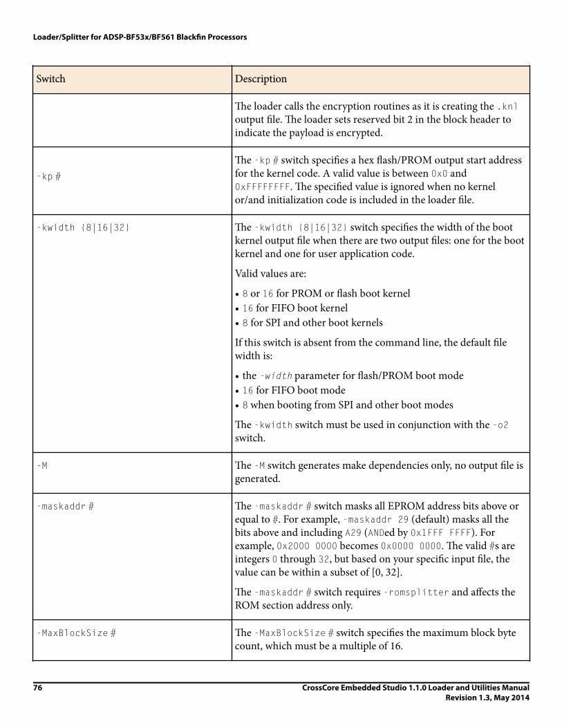
Switch Description
The loader calls the encryption routines as it is creating the .knloutput file. The loader sets reserved bit 2 in the block header toindicate the payload is encrypted.
-kp #The -kp # switch specifies a hex flash/PROM output start addressfor the kernel code. A valid value is between 0x0 and0xFFFFFFFF. The specified value is ignored when no kernelor/and initialization code is included in the loader file.
-kwidth {8|16|32} The -kwidth {8|16|32} switch specifies the width of the bootkernel output file when there are two output files: one for the bootkernel and one for user application code.
Valid values are:
• 8 or 16 for PROM or flash boot kernel• 16 for FIFO boot kernel• 8 for SPI and other boot kernels
If this switch is absent from the command line, the default filewidth is:
• the -width parameter for flash/PROM boot mode• 16 for FIFO boot mode• 8 when booting from SPI and other boot modes
The -kwidth switch must be used in conjunction with the -o2switch.
-M The -M switch generates make dependencies only, no output file isgenerated.
-maskaddr # The -maskaddr # switch masks all EPROM address bits above orequal to #. For example, -maskaddr 29 (default) masks all thebits above and including A29 (ANDed by 0x1FFF FFFF). Forexample, 0x2000 0000 becomes 0x0000 0000. The valid #s areintegers 0 through 32, but based on your specific input file, thevalue can be within a subset of [0, 32].
The -maskaddr # switch requires -romsplitter and affects theROM section address only.
-MaxBlockSize # The -MaxBlockSize # switch specifies the maximum block bytecount, which must be a multiple of 16.
Loader/Splitter for ADSP-BF53x/BF561 Blackfin Processors
76 CrossCore Embedded Studio 1.1.0 Loader and Utilities ManualRevision 1.3, May 2014

Switch Description
-MaxZeroFillBlockSize # The -MaxZeroFillBlockSize # switch specifies the maximumblock byte count for zero-filled blocks. The valid values are from0x0 to 0xFFFFFFF0, and the default value matches -MaxBlockSize #.
-MM The -MM switch generates make dependencies while producing theoutput files.
-Mo filename The -Mo filename switch writes make dependencies to thenamed file. Use the -Mo switch with either -M or -MM. If -Mo is notpresent, the default is a <stdout> display.
-Mt filenameThe -Mt filename switch specifies the make dependencies targetoutput file. Use the -Mt switch with either -M or -MM. If -Mt is notpresent, the default is the name of the input file with an .ldrextension.
-noFinalBlock The -noFinalBlock switch directs the loader utility not to makea special final block for TWI boot.
The switch applies to the ADSP-BF537 processors only.
-noFinalTag The -noFinalTag switch directs the loader utility not to set thefinal block tag for the first .dxe file. As a result, the boot processcontinues with code from the second .dxe file, following the firstfile.
The switch applies to the ADSP-BF56x processors only.
-noInitCode The -noInitCode switch directs the loader utility not to expectan initialization input file even though an external memorysection is present in the input .dxe file.
The switch applies to the ADSP-BF531/BF532/BF533, ADSP-BF534/BF536/BF537/BF538/BF539 processors only.
-noSecondStageKernel The -noSecondStageKernel switch directs the loader utility notto include a default second-stage kernel into the loader stream.
The switch applies to the ADSP-BF56x processors only.
-o filename The -o filename switch directs the loader utility to use thespecified file as the name of the loader utility's output file. If the
Loader/Splitter for ADSP-BF53x/BF561 Blackfin Processors
CrossCore Embedded Studio 1.1.0 Loader and Utilities ManualRevision 1.3, May 2014
77

Switch Description
filename is absent, the default name is the root name of theinput file with an .ldr extension.
-o2 The -o2 switch produces two output files: one for the init block (ifpresent) and boot kernel and one for user application code.
To have a different format, boot mode, or output width from theapplication code output file, use the -kb -kf -kwidth switchesto specify the boot mode, the boot format, and the boot width forthe output kernel file, respectively.
Combine -o2 with -l filename and/or -init filename on theADSP-BF531/BF532/BF533, ADSP-BF534/BF536/BF537/BF538/BF539, ADSP-BF561 processors.
-p # The -p # switch specifies a hex flash/PROM output start addressfor the application code. A valid value is between 0x0 and0xFFFFFFFF. A specified value must be greater than that specifiedby -kp if both kernel and/or initialization and application codeare in the same output file (a single output file).
-pflag {#|PF#|PG#|PH# } The -pflag { #|PF#|PG#|PH# } switch specifies a 4-bit hex valuefor a strobe (programmable flag) or for one of the ports: F, G, or H.There is no default value. The value is dynamic and varies withprocessor, silicon revision, boot mode, and width. The loadergenerates warnings for illegal combinations.
The -pFlag Values for ADSP-BF531/BF532/BF533 Processors, -pFlag Values for ADSP-BF534/BF536/BF537, and -pFlag Valuesfor ADSP-BF538/BF539 Processors tables show the valid valuesfor the switch.
The switch applies to the ADSP-BF531x and ADSP-BF561processors only.
-proc processor The -proc processor switch specifies the target processor.
The processor can be one of the following: ADSP-BF531, ADSP-BF532, ADSP-BF533, ADSP-BF534, ADSP-BF536, ADSP-BF537,ADSP-BF538, ADSP-BF539, ADSP-BF561.
-romsplitter The -romsplitter switch creates a non-bootable image only.This switch overwrites the -b switch and any other switchbounded by the boot mode.
Loader/Splitter for ADSP-BF53x/BF561 Blackfin Processors
78 CrossCore Embedded Studio 1.1.0 Loader and Utilities ManualRevision 1.3, May 2014

Switch Description
In the .ldf file, declare memory segments to be `split' as typeROM. The splitter skips RAM segments, resulting in an empty file ifall segments are declared as RAM. The -romsplitter switchsupports hex and ASCII formats.
-ShowEncryptionMessage The -ShowEncryptionMessage switch displays a messagereturned from the encryption function.
-si-revision [none|any|x.x] Sets revision for the build, with x.x being the revision number forthe processor hardware. If -si-revision is not used, the target isa default revision from the supported revisions.
-v The -v switch directs the loader utility to output verbose loadermessages and status information as the loader processes files.
-width {8|16|32} The -width {8|16|32} switch specifies the loader output file's width in bits. Valid values are 8 and 16, depending on the bootmode. The default value is 16 for FIFO boot mode and 8 for allother boot modes.
• For flash/PROM booting, the size of the output file depends onthe -width switch.
• For FIFO booting, the only available width is 16.• For SPI booting, the size of the output .ldr file is the same for
both -width 8 and -width 16. The only difference is theheader information.
-ZeroPadForced The -ZeroPadForced switch forces the loader utility to pad eachdata byte with a zero byte for 16-bit output. Use this switch only ifyour system requires zero padding in a loader file. Use this switchwith caution: arbitrating pad data with zeros can cause the loaderfile to fail. The loader utility performs default zero paddingautomatically in general.
The switch applies to the ADSP-BF531/BF532/BF533/BF534,ADSP-BF536/BF537/BF538/BF539 processors only.
Loader/Splitter for ADSP-BF53x/BF561 Blackfin Processors
CrossCore Embedded Studio 1.1.0 Loader and Utilities ManualRevision 1.3, May 2014
79

Table 16. -pFlag Values for ADSP-BF531/BF532/BF533 Processors. (The ADSP-BF531/BF532/BF533 processorsalways have the RESVECT bit (bit 2 in the block header fla word) cleared.)
Silicon Revision 0.6
Width 8 16
Flash boot mode NONE NONE
SPI boot mode NONE
SPI slave boot mode 1-15
PF1-15
Table 17. -pFlag Values for ADSP-BF534/BF536/BF537. (The ADSP-BF534/BF536/BF537 processors alwayshave the RESVECT bit (bit 2 in the block header fla word) set.)
Silicon Revision 0.3
Width 8 16
Flash boot mode NONE
PF0-15
PG0-15
PH0-15
NONE
PF0-15
PG0-15
PH0-15
SPI boot mode NONE
PF0-9
PF15
PG0-15
PH0-15
SPI slave boot mode NONE
PF0-10
PF15
PG0-15
Loader/Splitter for ADSP-BF53x/BF561 Blackfin Processors
80 CrossCore Embedded Studio 1.1.0 Loader and Utilities ManualRevision 1.3, May 2014

Silicon Revision 0.3
PH0-15
TWI boot mode NONE
PF0-15
PG0-15
PH0-15
TWI slave boot mode NONE
PF0-15
PG0-15
PH0-15
UART boot mode NONE
PF2-15
PG0-15
PH0-15
FIFO boot mode NONE
PF0
PF2-15
PG0-15
PH0-15
Table 18. -pFlag Values for ADSP-BF538/BF539 Processors
Silicon Revision All
Width 8 16
Flash boot mode NONE NONE
SPI boot mode NONE
Loader/Splitter for ADSP-BF53x/BF561 Blackfin Processors
CrossCore Embedded Studio 1.1.0 Loader and Utilities ManualRevision 1.3, May 2014
81

Silicon Revision All
SPI slave boot mode 1-15
PF1-15
iNote:
The ADSP-BF538/BF539 processors always have the RESVECT bit (bit 2 in the block header flag word) set.
CCES Loader and Splitter Interface for ADSP-BF53x/BF561 ProcessorsOnce a project is created in the CrossCore Embedded Studio IDE, you can change the project's output (artifact)type.
The IDE invokes the elfloader.exe utility to build the output loader file. To modify the default loaderproperties, use the project's Tool Settings dialog box. The controls on the pages correspond to the loadercommand-line switches and parameters (see Loader Command-Line Switches for ADSP-BF533/BF561Processors). The loader utility for Blackfin processors also acts as a ROM splitter when evoked with thecorresponding switches.
The loader pages (also called loader properties pages) show the default loader settings for the project's targetprocessor. Refer to the CCES online help for information about the loader/splitter interface.
Loader/Splitter for ADSP-BF53x/BF561 Blackfin Processors
82 CrossCore Embedded Studio 1.1.0 Loader and Utilities ManualRevision 1.3, May 2014
5Loader/Splitter for ADSP-BF60x Blackfi Processors
This chapter explains how the loader/splitter utility (elfloader.exe) is used to convert executable (.dxe) filesinto boot-loadable or non-bootable files for the ADSP-BF60x Blackfin processors.
Refer to the Introduction chapter for the loader utility overview. Loader operations specific to the ADSP-BF60xBlackfin processors are detailed in the following sections.
• ADSP-BF60x Processor Booting
Provides general information on various boot modes.• ADSP-BF60x Processor Loader Guide
Provides information on how to build loader files.
ADSP-BF60x Processor BootingFor detailed information on the boot loader stream and modes for the ADSP-BF60x processors, refer to thebooting chapter of the ADSP-BF60x Blackfin Processor Hardware Reference.
Refer to the processor's data sheet and hardware reference manual for detailed information on systemconfiguration, peripherals, registers, and operating modes.
• Blackfin processor data sheets can be found at:
http://www.analog.com/en/embedded-processing-dsp/blackfin/processors/data-sheets/resources/index.html.• Blackfin processor manuals can be found at:
http://www.analog.com/en/embedded-processing-dsp/blackfin/processors/manuals/resources/index.html ordownloaded into the CCES IDE via Help > Install New Software.
The ADSP-BF60x Part Numbers table lists the part numbers that currently comprise the ADSP-BF60x family ofBlackfin processors. Future releases of CrossCore Embedded Studio may support additional processors.
Loader/Splitter for ADSP-BF60x Blackfin Processors
CrossCore Embedded Studio 1.1.0 Loader and Utilities ManualRevision 1.3, May 2014
83

Table 19. ADSP-BF60x Part Numbers
ADSP-BF606 ADSP-BF608
ADSP-BF607 ADSP-BF609
This section covers the following topics:
• ADSP-BF60x Processor Boot Modes• ADSP-BF60x BCODE Field for Memory, RSI, and SPI Master Boot• Building a Dual-Core Application• CRC32 Protection• Block Sizes
ADSP-BF60x Processor Boot Modes
Table 20. ADSP-BF60x Processor Boot Modes
ADSP-BF60x Boot Mode Boot (-b) Boot Code (-bcode) Notes
MEMORY -b MEMORY -bcode #2 Generic memory boot mode.Replaces -b FLASH. The argument forthe -bcode switch is the MDMACODE,one of the supported numeric valuesspecific to memory boot.
RSI0 master -b RSI -bcode # The argument for the -bcode switchis the RSICODE, one of the supportednumeric values specific to RSI masterboot.
SPI0 master -b SPI -bcode # The argument for the -bcode switchis the SPIMCODE, one of the supportednumeric values specific to SPI masterboot.
SPI0 slave -b SPISLAVE Boot code field in headers is not usedfor slave boot modes.
2 Legal values for the -bcode # switch can be found in the booting chapter of the ADSP-BF60x BlackfinProcessor Hardware Reference.
Loader/Splitter for ADSP-BF60x Blackfin Processors
84 CrossCore Embedded Studio 1.1.0 Loader and Utilities ManualRevision 1.3, May 2014

ADSP-BF60x Boot Mode Boot (-b) Boot Code (-bcode) Notes
LP0 slave -b LPSLAVE Boot code field in headers is not usedfor slave boot modes.
UART0 slave -b UARTSLAVE Boot code field in headers is not usedfor slave boot modes.
ADSP-BF60x BCODE Field for Memory, RSI, and SPI Master BootA bootable loader stream is a series of boot blocks, each block beginning with a block header. Bits 0:3 of theADSP-BF60x block header is a boot mode specific code field known as BCODE. The -bcode # switch controlswhat value is written to the BCODE field in the block headers in a bootable loader stream.
For detailed information on .ldr block headers, see the booting chapter of the ADSP-BF60x Blackfin ProcessorHardware Reference.
The loader requires an explicit BCODE value when creating loader streams for master boot modes. For the ADSP-BF60x processors, this includes memory, RSI, and SPI master boot modes. When used in the context of a specificboot mode, BCODE is referred to by its boot-specific name: MDMACODE for memory boot, RSICODE for RSI boot,and SPIMCODE for SPI master boot.
iNote:
The -bcode switch is not used for slave boot modes. The BCODE field is zero for slave boot modes.
When building loader streams, explicitly specify the BCODE field for the .ldr block headers:
1. Open the Properties dialog box for the project.2. Choose C/C++ Build > Settings. The Tool Settings page appears.3. Click General under CrossCore Blackfin Loader. The loader General properties page appears.4. In Boot code (-bcode), enter the number.
The BCODE is specific for that particular boot mode. For -bcode # valid values, see the booting chapter of theADSP-BF60x Blackfin Processor Hardware Reference.
5. Click OK to close the dialog box.6. Click Apply.
If you do not specify -bcode #, the loader reports Error ld0260. For example, if -bcode # is not present whenbuilding a loader stream for RSI boot:
[Error ld0260]: Missing boot code header value for target ADSP-BF609 block headers.
The -bcode # switch is required for specifying the boot code value
for boot modes MEMORY, RSI, and SPI.
For MEMORY boot, consult the MDMACODE table.
For RSI boot, consult the RSICODE table.
Loader/Splitter for ADSP-BF60x Blackfin Processors
CrossCore Embedded Studio 1.1.0 Loader and Utilities ManualRevision 1.3, May 2014
85

For SPI boot, consult the SPIMCODE table.
Building a Dual-Core ApplicationWhen building a dual-core application, use the -NoFinalTag switch to append the core 1 processing to core 0.The loader processes the input executables (.dxe) in order. If building at the command-line, placeDualCoreApp_Core1.dxe after DualCoreApp.dxe:
elfloader -proc ADSP-BF609 -b SPI -bcode 0x1 DualCoreApp.dxe -NoFinalTag="DualCoreApp.dxe"
DualCoreApp_Core1.dxe -o DualCoreApp.ldr -f HEX -Width 8
iNote:
Since the default startup code does not include functionality to allow core 0 to enable core 1, a convenientway to enable core 1 is to use the adi_core_1_enable function in the main program of DualCoreApp.
-NoFinalTagUse the -NoFinalTag switch for multi-core booting.
Syntax
-NoFinalTag[="DxeFile"]
iNote:
Note there is no white space around = when specifying the executable name.
The -NoFinalTag switch directs the loader utility not to set the FINAL flag on the last code block from the .dxefile. When building an .ldr file with multiple .dxe files, this prevents the boot from halting after the first .dxecompletes.
The loader processes the input .dxe files in the order they appear on the elfloader command-line. If the -NoFinalTag doesn't include the DxeFile file argument, it defaults to the first application .dxe file. Thus, thefollowing command applies -NoFinalTag to Core0.dxe:
elfloader -proc ADSP-BF609 -b SPI -bcode 0x1 -init BF609_init_v00.dxe Core0.dxe-NoFinalTag Core1.dxe -o DualCoreApp.ldr -f HEX -Width 8
You can explicitly specify the .dxe file to which -NoFinalTag applies. The following example is equivalent to theprevious command:
elfloader -proc ADSP-BF609 -b SPI -bcode 0x1 -init BF609_init_v00.dxe Core0.dxe-NoFinalTag="Core0.dxe" Core1.dxe -o DualCoreApp.ldr -f HEX -Width 8
The -NoFinalTag with a .dxe argument can appear multiple times. In the following example, there are fourapplication .dxe files, and the -NoFinalTag switch appears twice, scoped to the appropriate .dxe:
elfloader -proc ADSP-BF609 -b spi -bcode 0x1 -f hex -width 8 -o multicore.ldrRel/App0_Core0.dxe Rel/App0_Core1.dxe Rel/App1_Core0.dxe Rel/App1_Core1.dxe-NoFinalTag="App0_Core0.dxe" -NoFinalTag="App1_Core0.dxe"
Loader/Splitter for ADSP-BF60x Blackfin Processors
86 CrossCore Embedded Studio 1.1.0 Loader and Utilities ManualRevision 1.3, May 2014

As long as the .dxe files on the command line are uniquely named, you only need to specify the .dxe file name,without a full path. If the .dxe files are not uniquely named, the -NoFinalTag .dxe files must be matched bypaths. When specifying pathnames, use forward slash (/).
elfloader -proc ADSP-BF609 -b spi -bcode 0x1 -f hex -width 8 -o multicore.ldrAppA/App_Core0.dxe AppA/App_Core1.dxe AppB/App_Core0.dxe AppB/App_Core1.dxe-NoFinalTag="AppA/App_Core0.dxe" -NoFinalTag="AppB/App_Core0.dxe" -verbose
Use -verbose to get a "per dxe file" build summary from elfloader:
*** Summary of -NoFinalTag usage
NoFinalTag AppA/App_Core0.dxe was successful
-NoFinalTag AppB/App_Core0.dxe was successful
Any -NoFinalTag .dxe file that did not get a match gets a warning, with or without -verbose:
[Warning ld0265]: 'unknown.dxe' from -NoFinalTag switch resulted in no matches.
Programming Memory on a Target BoardUse the CCES Device Programmer utility (cldp) for programming the memory on a target board.
In the building a dual-core application example above, DualCoreApp.ldr was built for boot mode SPIO masterwith format hex.
Driver:
ADSP-BF609_EZBoard/Examples/Device_Programmer/serial/w25q32bv_dpia/w25q32bv_dpia.dxe
cldp -proc ADSP-BF609 -emu HPUSB -driver w25q32bv_dpia.dxe-cmd prog -erase affected -offset 0 -format hex -file DualCoreApp.ldr
iNote:
You can save the device programmer commands to a file:
cldp -@ myPath/SPI_Flash_Programming.txt
See the Device Programmer section in the CCES online help for more information (search help for "deviceprogrammer").
CRC32 ProtectionADSP-BF60x CRC32 protection is implemented in hardware. The boot kernel provides mechanisms to alloweach block to be verified using a 32-bit CRC.
When building a LDR file for CRC32 protection, use the -CRC32 <PolynomialCoefficient> switch.
-CRC32 (PolynomialCoefficient)
The -CRC32 switch directs the loader to generate CRC32 checksums. It uses the polynomial coefficient ifspecified, otherwise uses the default coefficient (0xD8018001).
Loader/Splitter for ADSP-BF60x Blackfin Processors
CrossCore Embedded Studio 1.1.0 Loader and Utilities ManualRevision 1.3, May 2014
87

Block SizesThe loader creates blocks with payload and fill blocks using default maximum size and alignment that meets therequirements of the target hardware. Switches are available to override the defaults.
Table 21. ADSP-BF60x Processor Block Sizes
Switch Description Default Requirements
-MaxBlockSize # Specify the maximumblock byte count
Loader uses maximumblock size 0x7FFFFFF0 asdefault
The maximum block sizeis limited to 0xFFFFFFFCbytes and must be amultiple of 4.
-MaxFillBlockSize # Specify the maximum fillblock byte count
Loader uses maximum fillblock size 0x7FFFFFF0 asdefault
The maximum fill blocksize is limited to0xFFFFFFFC bytes andmust be a multiple of 4.
ADSP-BF60x Processor Loader GuideThe loader utility post processes executable (.dxe) files and generates loader (.ldr) files. A loader file can beformatted as binary, ASCII or Intel hex style. An .ldr file contains the boot stream in a format expected by theon-chip boot kernel.
Loader utility operations depend on the loader properties, which control how the utility processes executablefiles. You select features, such as boot modes, boot kernels, and output file formats via the properties. Theproperties are specified on the loader utility's command line or the Tool Settings dialog box in the IDE(CrossCore Blackfin Loader pages). The default loader settings for a selected processor are preset in the IDE.
iNote:
The IDE’s Tool Settings correspond to switches displayed on the command line.
These sections describe how to produce a bootable (single and multiple) or non-bootable loader file:
• CCES Loader and Splitter Interface for ADSP-BF60x Processors• ROM Splitter Capabilities for ADSP-BF60x Processors• ADSP-BF60x Loader Collateral
CCES Loader and Splitter Interface for ADSP-BF60x ProcessorsOnce a project is created in the CrossCore Embedded Studio IDE, you can change the project's output (artifact)type.
Loader/Splitter for ADSP-BF60x Blackfin Processors
88 CrossCore Embedded Studio 1.1.0 Loader and Utilities ManualRevision 1.3, May 2014

The IDE invokes the elfloader.exe utility to build the output loader file. To modify the default loaderproperties, use the project's Tool Settings dialog box. The controls on the pages correspond to the loadercommand-line switches and parameters. Refer to the online help for more information.
ROM Splitter Capabilities for ADSP-BF60x Processors
iNote:
The readall feature is available for the automatic merging of fixed-position ROM data with code blockswithin the bootable loader stream and typically supersedes the use of the legacy romsplitter featuredescribed below.
When the loader utility is invoked with the splitter capabilities, it does not format the application data whentransforming a .dxe file to an .ldr file. The splitter emits raw data only. Whether data and/or instructionsections are processed by the loader or by the splitter depends upon the LDF's TYPE() command. Sectionsdeclared with TYPE(RAM) are consumed by the loader, and sections declared by TYPE(ROM) are consumed by thesplitter.
The contents of the ROM memory segments are extracted from the .dxe. The contents of the ROM segments getwritten to the .ldr file in raw format, each segment preceded by header words. The header consists of thefollowing four 32-bit words written in unprefixed hex format:
Address Start address of ROM memory segment (as defined in LDF)
Length # of bytes extracted from the DXE for this segment
Control Word 32 bit control word
00
xx address multiply
xx logical width
xx physical width
Reserved word All zeros
Example - ASCII Formatted Splitter .ldr File
This is an example of the header preceding the raw content extracted from the .dxe for segment MEM1.
Assume 256 bytes were written to the .ldr file and MEM1 was defined in the LDF as:
MEM1 { TYPE(ROM) WIDTH(8) START(0xB0000000) END( 0xB3FFFFFF) }
The -romsplitter .ldr output will be:
Loader/Splitter for ADSP-BF60x Blackfin Processors
CrossCore Embedded Studio 1.1.0 Loader and Utilities ManualRevision 1.3, May 2014
89
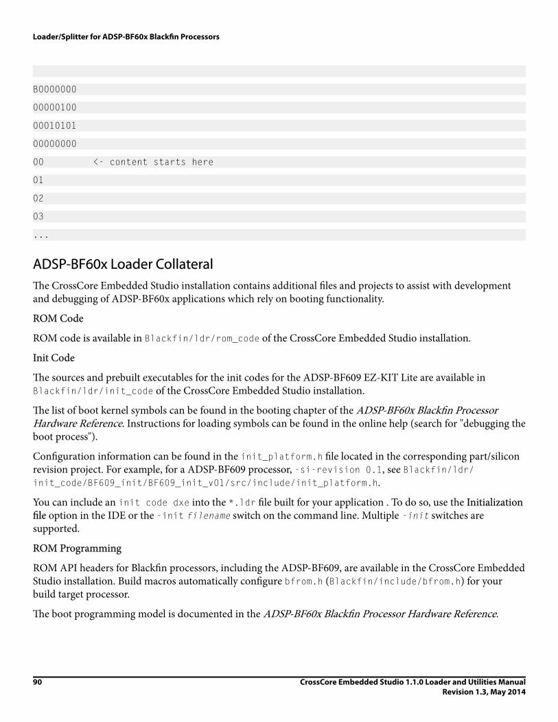
B0000000
00000100
00010101
00000000
00 <- content starts here
01
02
03
...
ADSP-BF60x Loader CollateralThe CrossCore Embedded Studio installation contains additional files and projects to assist with developmentand debugging of ADSP-BF60x applications which rely on booting functionality.
ROM Code
ROM code is available in Blackfin/ldr/rom_code of the CrossCore Embedded Studio installation.
Init Code
The sources and prebuilt executables for the init codes for the ADSP-BF609 EZ-KIT Lite are available inBlackfin/ldr/init_code of the CrossCore Embedded Studio installation.
The list of boot kernel symbols can be found in the booting chapter of the ADSP-BF60x Blackfin ProcessorHardware Reference. Instructions for loading symbols can be found in the online help (search for "debugging theboot process").
Configuration information can be found in the init_platform.h file located in the corresponding part/siliconrevision project. For example, for a ADSP-BF609 processor, -si-revision 0.1, see Blackfin/ldr/init_code/BF609_init/BF609_init_v01/src/include/init_platform.h.
You can include an init code dxe into the *.ldr file built for your application . To do so, use the Initializationfile option in the IDE or the -init filename switch on the command line. Multiple -init switches aresupported.
ROM Programming
ROM API headers for Blackfin processors, including the ADSP-BF609, are available in the CrossCore EmbeddedStudio installation. Build macros automatically configure bfrom.h (Blackfin/include/bfrom.h) for yourbuild target processor.
The boot programming model is documented in the ADSP-BF60x Blackfin Processor Hardware Reference.
Loader/Splitter for ADSP-BF60x Blackfin Processors
90 CrossCore Embedded Studio 1.1.0 Loader and Utilities ManualRevision 1.3, May 2014
6Loader/Splitter for ADSP-BF70x Blackfi Processors
This chapter explains how the loader/splitter utility (elfloader.exe) is used to convert executable (.dxe) filesinto boot-loadable or non-bootable files for the ADSP-BF70x Blackfin processors.
Refer to the Introduction chapter for the loader utility overview. Loader operations specific to the ADSP-BF70xBlackfin processors are detailed in the following sections.
• ADSP-BF70x Processor Booting
Provides general information on various boot modes.• ADSP-BF70x Processor Loader Guide
Provides information on how to build loader files.
ADSP-BF70x Processor BootingFor detailed information on the boot loader stream and modes for the ADSP-BF70x processors, refer to thebooting chapter of the ADSP-BF70x Blackfin+ Processor Hardware Reference.
Refer to the processor's data sheet and hardware reference manual for detailed information on systemconfiguration, peripherals, registers, and operating modes.
• Blackfin processor data sheets can be found at:
http://www.analog.com/en/embedded-processing-dsp/blackfin/processors/data-sheets/resources/index.html.
The ADSP-BF70x Part Numbers table lists the part numbers that currently comprise the ADSP-BF70x family ofBlackfin processors. Future releases of CrossCore Embedded Studio may support additional processors.
Table 22. ADSP-BF70x Part Numbers
ADSP-BF700 ADSP-BF701 ADSP-BF702
ADSP-BF702 ADSP-BF704 ADSP-BF706
Loader/Splitter for ADSP-BF70x Blackfin Processors
CrossCore Embedded Studio 1.1.0 Loader and Utilities ManualRevision 1.3, May 2014
91

ADSP-BF703 ADSP-BF705 ADSP-BF707
This section covers the following topics:
• ADSP-BF70x Processor Boot Modes• ADSP-BF70x BCODE Field for SPI Boot• CRC32 Protection• Block Sizes
ADSP-BF70x Processor Boot Modes
Table 23. ADSP-BF70x Processor Boot Modes
ADSP-BF70x Boot Mode Boot (-b) Boot Code (-bcode) Notes
SPI master -b SPI -bcode #3 The argument for the -bcode switch is theSPIMCODE, one of thesupported numeric valuesspecific to SPI masterboot.
SPI slave -b SPISLAVE Not applicable Boot code field in headersis not used for slave bootmodes.
UART slave -b UARTSLAVE Not applicable Boot code field in headersis not used for slave bootmodes.
ADSP-BF70x BCODE Field for SPI BootA bootable loader stream is a series of boot blocks, each block beginning with a block header. Bits 0:3 of theADSP-BF70x block header is a boot mode specific code field known as BCODE. The -bcode # switch controlswhat value is written to the BCODE field in the block headers in a bootable loader stream.
For detailed information on .ldr block headers, see the booting chapter of the ADSP-BF70x Blackfin+Processor Hardware Reference manual.
3 Values for the -bcode # switch can be found in the booting chapter of the ADSP-BF70x Blackfin+Processor Hardware Reference.
Loader/Splitter for ADSP-BF70x Blackfin Processors
92 CrossCore Embedded Studio 1.1.0 Loader and Utilities ManualRevision 1.3, May 2014

The loader requires an explicit BCODE value when creating loader streams for master boot modes. For the ADSP-BF70x processors, this is SPI master boot mode. When used in the context of SPI mater boot mode, BCODE isreferred to by its boot-specific name, SPIMCODE.
iNote:
The -bcode switch is not used for slave boot modes. The BCODE field is zero for slave boot modes.
When building loader streams, explicitly specify the BCODE field for the .ldr block headers:
1. Open the Properties dialog box for the project.2. Choose C/C++ Build > Settings. The Tool Settings page appears.3. Click General under CrossCore Blackfin Loader. The loader General properties page appears.4. In Boot code (-bcode), enter the number.
The BCODE is specific for that particular boot mode. For -bcode # valid values, see the booting chapter of theADSP-BF70x Blackfin+ Processor Hardware Reference.
5. Click OK to close the dialog box.6. Click Apply.
If you do not specify -bcode #, the loader reports Error ld0274. For example, if -bcode # is not present whenbuilding a loader stream for SPI boot:
[Error ld0274]: Missing boot code header value for target ADSP-BF707 block headers.
The -bcode # switch is required for specifying the boot code value for
the SPI boot modes. Consult the SPIMCODE table.
Secure Boot and Encrypted ImagesThe ADSP-BF70x processors provide security features for secure booting and encryption. Creating signed andoptionally encrypted images is a multistage process using the Blackfin loader and signing utility(signtool.exe). The Blackfin loader builds the boot image in binary format, while the signtool protects thatboot image.
1. LDR file creation:
Build an .ldr file in CrossCore Embedded Studio or via the command-line.
iNote:
For secure booting, the .ldr file must be built in binary format (-f binary). The signtool utility treatsit as raw binary data with no interpretation. If the .ldr file is not built in binary format, the resultingsecure-boot image is not be usable.
2. Secure-boot image creation:
To sign/encrypt the boot image, use the signtool utility, either as a post-build step in the .ldr file build in theIDE or via the command-line. Refer to the signtool documentation in the Utilities appendix.
Using signtool to build a signed and optionally encrypted images in CCES:
Loader/Splitter for ADSP-BF70x Blackfin Processors
CrossCore Embedded Studio 1.1.0 Loader and Utilities ManualRevision 1.3, May 2014
93

The CCES IDE invokes the signtool utility after the main build, in a user-specified post-build step. The post-build step is helpful for the repetitive steps of creating a binary .ldr file and signing and optionally encrypting it:
To specify the post-build step:
iNote:
The post-build step is executed only if the main build has executed successfully.
1. It is assumed that the project's Build Artifact type is a Loader File2. Select the project in a navigation view:
a. From the context menu, choose Properties > C++ Build > Settings. The Settings dialog box appears.b. Click Build Steps. The Build Steps dialog box appears.
3. In Post-build steps, type the signtool command for signing and optional encrypting:
signtool genkeypair –algo ecdsa224 –outfile keypair.der
iNote:
The signtool sign step requires the keypair file as input in addition to the .ldr stream. Typically thekeypair file is created in a one-time up-front setup operation.
4. Click OK
CRC32 ProtectionADSP-BF70x CRC32 protection is implemented in hardware. The boot kernel provides mechanisms to alloweach block to be verified using a 32-bit CRC.
When building a LDR file for CRC32 protection, use the -CRC32 <PolynomialCoefficient> switch.
-CRC32 (PolynomialCoefficient)
The -CRC32switch directs the loader to generate CRC32 checksums. It uses the polynomial coefficient ifspecified, otherwise uses the default coefficient (0xD8018001).
Block SizesThe loader creates blocks with payload and fill blocks using default maximum size and alignment that meets therequirements of the target hardware. Switches are available to override the defaults.
Loader/Splitter for ADSP-BF70x Blackfin Processors
94 CrossCore Embedded Studio 1.1.0 Loader and Utilities ManualRevision 1.3, May 2014

Table 24. ADSP-BF70x Processor Block Sizes
Switch Description Default Requirements
-MaxBlockSize # Specify the maximumblock byte count
Loader uses maximumblock size 0x7FFFFFF0 asdefault
The maximum block sizeis limited to 0xFFFFFFFCbytes and must be amultiple of 4.
-MaxFillBlockSize # Specify the maximum fillblock byte count
Loader uses maximum fillblock size 0x7FFFFFF0 asdefault
The maximum fill blocksize is limited to0xFFFFFFFC bytes andmust be a multiple of 4.
ADSP-BF70x Processor Loader GuideThe loader utility post processes executable (.dxe) files and generates loader (.ldr) files. A loader file can beformatted as binary, ASCII or Intel hex style. An .ldr file contains the boot stream in a format expected by theon-chip boot kernel.
Loader utility operations depend on the loader properties, which control how the utility processes executablefiles. You select features, such as boot modes, boot kernels, and output file formats via the properties. Theproperties are specified on the loader utility's command line or the Tool Settings dialog box in the IDE (theCrossCore Blackfin Loader pages). The default loader settings for a selected processor are preset in the IDE.
iNote:
The IDE’s Tool Settings correspond to switches displayed on the command line.
These sections describe how to produce a bootable or non-bootable loader file:
• CCES Loader and Splitter Interface for ADSP-BF70x Processors• ROM Splitter Capabilities for ADSP-BF70x Processors• ADSP-BF70x Loader Collateral
CCES Loader and Splitter Interface for ADSP-BF70x ProcessorsOnce a project is created in the CrossCore Embedded Studio IDE, you can change the project's output (artifact)type.
The IDE invokes the elfloader.exe utility to build the output loader file. To modify the default loaderproperties, use the project's Tool Settings dialog box. The controls on the pages correspond to the loadercommand-line switches and parameters. Refer to the online help for more information.
Loader/Splitter for ADSP-BF70x Blackfin Processors
CrossCore Embedded Studio 1.1.0 Loader and Utilities ManualRevision 1.3, May 2014
95

ROM Splitter Capabilities for ADSP-BF70x Processors
iNote:
The readall feature is available for the automatic merging of fixed-position ROM data with code blockswithin the bootable loader stream and typically supersedes the use of the legacy romsplitter featuredescribed below.
When the loader utility is invoked with the splitter capabilities, it does not format the application data whentransforming a .dxe file to an .ldr file. The splitter emits raw data only. Whether data and/or instructionsections are processed by the loader or by the splitter depends upon the LDF's TYPE() command. Sectionsdeclared with TYPE(RAM) are consumed by the loader, and sections declared by TYPE(ROM) are consumed by thesplitter.
The contents of the ROM memory segments are extracted from the .dxe. The contents of the ROM segments getwritten to the .ldr file in raw format, each segment preceded by header words. The header consists of thefollowing four 32-bit words written in unprefixed hex format:
Address Start address of ROM memory segment (as defined in LDF)
Length # of bytes extracted from the DXE for this segment
Control Word 32 bit control word
00
xx address multiply
xx logical width
xx physical width
Reserved word All zeros
Example - ASCII Formatted Splitter .ldr File
This is an example of the header preceding the raw content extracted from the .dxe for segment MEM1.
Assume 256 bytes were written to the .ldr file and MEM1 was defined in the LDF as:
MEM1 { TYPE(ROM) WIDTH(8) START(0xB0000000) END( 0xB3FFFFFF) }
The -romsplitter .ldr output will be:
B0000000
00000100
00010101
Loader/Splitter for ADSP-BF70x Blackfin Processors
96 CrossCore Embedded Studio 1.1.0 Loader and Utilities ManualRevision 1.3, May 2014

00000000
00 <- content starts here
01
02
03
...
ADSP-BF70x Loader CollateralThe CrossCore Embedded Studio installation contains additional files and projects to assist with developmentand debugging of ADSP-BF70x applications which rely on booting functionality.
ROM Code
The sources for ROM code are not available in the CrossCore Embedded Studio to protect the ADSP-BF70xsecure booting and encryption details.
Init Code
The sources and prebuilt executables for the init codes for the ADSP-BF707 EZ-KIT Lite are available inBlackfin/ldr/init_code of the CrossCore Embedded Studio installation.
The list of boot kernel symbols can be found in the booting chapter of the ADSP-BF70x Blackfin+ ProcessorHardware Reference. Instructions for loading symbols can be found in the online help (search for "debugging theboot process").
Configuration information can be found in the init_platform.h file located in the corresponding part/siliconrevision project. For example, for a ADSP-BF707 processor, -si-revision 0.0, see Blackfin/ldr/init_code/BF707_init/BF707_init_v00/src/include/init_platform.h.
You can include an init code dxe into the .ldr file built for your application . To do so, use the Initializationfile option in the IDE or the -init filename switch on the command line. Multiple -init switches aresupported.
ROM Programming
iNote:
The ADSP-BF707 sample init code example is provided for non-secure booting. Init code or any form ofcallback is not supported in secure boot because the code is inherently insecure.
ROM API headers for Blackfin processors, including the ADSP-BF707 processors, are available in the CrossCoreEmbedded Studio installation. Build macros automatically configure bfrom.h (Blackfin/include/bfrom.h)for your build target processor.
The boot programming model is documented in the ADSP-BF70x Blackfin+ Processor Hardware Reference.
Loader/Splitter for ADSP-BF70x Blackfin Processors
CrossCore Embedded Studio 1.1.0 Loader and Utilities ManualRevision 1.3, May 2014
97


7Loader for ADSP-21160 SHARC Processors
This chapter explains how the loader utility (elfloader.exe) is used to convert executable (.dxe) files intoboot-loadable files for the ADSP-21160 SHARC processors.
Refer to the Introduction chapter for the loader utility overview; the introductory material applies to allprocessor families. Refer to Loader for ADSP-21161 SHARC Processors chapter for information about theADSP-21161 processors. Refer to Loader for ADSP-2126x/2136x/2137x/214xx SHARC Processors chapter forinformation about the ADSP-2126x and ADSP-2136x processors.
Loader operations specific to the SHARC processors are detailed in the following sections.
• ADSP-21160 Processor Booting
Provides general information about various booting modes, including information about boot kernels.• ADSP-21160 Processor Loader Guide
Provides reference information about the loader utility's graphical user interface, command-line syntax, andswitches.
ADSP-21160 Processor BootingThe processors support three boot modes: EPROM, host, link port, and no-boot (see the ADSP-21160 BootMode Pins and ADSP-21160 Boot Modes tables in Boot Mode Selection). Boot-loadable files for these modespack boot data into 48-bit instructions and use an appropriate DMA channel of the processor's DMA controllerto boot-load the instructions.
iNote:
The ADSP-21160 processors use DMAC8 for link port booting and DMAC10 for the host and EPROMbooting.
• When booting from an EPROM through the external port, the processor reads boot data from an 8-bitexternal EPROM.
• When booting from a host processor through the external port, the processor accepts boot data from a 8- or16-bit host microprocessor.
Loader for ADSP-21160 SHARC Processors
CrossCore Embedded Studio 1.1.0 Loader and Utilities ManualRevision 1.3, May 2014
99

• When booting through the link port, the processor receives boot data as 4-bit wide data in link buffer 4.• In no-boot mode, the processor begins executing instructions from external memory.
Software developers who use the loader utility should be familiar with the following operations.
• Power-Up Booting Process• Boot Mode Selection• ADSP-21160 Boot Modes• ADSP-21160 Boot Kernels• ADSP-21160 Interrupt Vector Table• ADSP-21160 Multi-Application (Multi-DXE) Management• ADSP-21160 Processor ID Numbers
Power-Up Booting ProcessThe ADSP-21160 processors include a hardware feature that boot-loads a small, 256-instruction program intothe processor's internal memory after power-up or after the chip reset. These instructions come from a programcalled boot kernel. When executed, the boot kernel facilitates booting of user application code. The combinationof the boot kernel and application code comprise the boot-loadable (.ldr) file.
At power-up, after the chip reset, the booting process includes the following steps.
1. Based on the boot type, an appropriate DMA channel is automatically configured for a 256-instruction (48-bit) transfer. This transfer boot-loads the boot kernel program into the processor memory. DMA channelsused by various processor models are shown in the Processor DMA Channels table.
Table 25. Processor DMA Channels
Processor PROM Booting Host Booting Link Booting
ADSP-21160 DMAC104 DMAC10 DMAC8
2. The boot kernel runs and loads the application executable code and data.3. The boot kernel overwrites itself with the first 256 words of the application at the end of the booting process.
After that, the application executable code begins to execute from location 0x40000 (ADSP-21160). The startaddresses and reset vector addresses are summarized in the Processor Start Addresses table.
4 See the DMA Settings for ADSP-21160 EPROM Booting table in EPROM Boot Mode.
Loader for ADSP-21160 SHARC Processors
100 CrossCore Embedded Studio 1.1.0 Loader and Utilities ManualRevision 1.3, May 2014

Table 26. Processor Start Addresses
Processor Start Address Reset Vector Address5
ADSP-21160 0x40000 0x40004
The boot type selection directs the system to prepare the appropriate boot kernel.
Boot Mode SelectionThe state of various pins selects the processor boot mode. See the ADSP-21160 Boot Mode Pins andADSP-21160 Boot Modes tables.
Table 27. ADSP-21160 Boot Mode Pins
Pin Type Description
EBOOT I EPROM boot. When EBOOT is high, the processor boot-loadsfrom an 8-bit EPROM through the processor's external port.When EBOOT is low, the LBOOT and BMS pins determine thebooting mode.
LBOOT I Link port boot. When LBOOT is high and EBOOT is low, theprocessor boots from another SHARC through the link port.When LBOOT is low and EBOOT is low, the processor boots from ahost processor through the processor's external port.
BMS I/O/T6 Boot memory select. When boot-loading from an EPROM(EBOOT=1 and LBOOT=0), this pin is an output and serves as thechip select for the EPROM. In a multiprocessor system, BMS isoutput by the bus master. When host-booting or link-booting(EBOOT=0), BMS is an input and must be high.
5 The reset vector address must not contain a valid instruction since it is not executed during the bootingsequence. Place a NOP or IDLE instruction at this location.
6 Three-statable in EPROM boot mode (when BMS is an output).
Loader for ADSP-21160 SHARC Processors
CrossCore Embedded Studio 1.1.0 Loader and Utilities ManualRevision 1.3, May 2014
101

Table 28. ADSP-21160 Boot Modes
EBOOT LBOOT BMS Boot Mode
0 0 0 (Input) No-boot (processor executes from externalmemory)
0 0 1 (Input) Host processor
0 1 0 (Input) Reserved
0 1 1 (Input) Link port
1 0 Output EPROM (BMS is chip select)
1 1 x (Input) Reserved
ADSP-21160 Boot ModesThe processors support these boot modes: EPROM, host, and link. The following sections describe each of themodes.
• EPROM Boot Mode• Host Boot Mode• Link Port Boot Mode• No-Boot Mode
For multiprocessor booting, refer to ADSP-21160 Multi-Application (Multi-DXE) Management.
EPROM Boot ModeThe processor is configured for EPROM boot through the external port when the EBOOT pin is high and the LBOOT pin is low. These settings cause the BMS pin to become an output, serving as chip select for the EPROM.The PROM Connections to Processors table lists all PROM-to-processor connections.
Table 29. PROM Connections to Processors
Processor Connection
ADSP-21160 PROM/EPROM connects to DATA39-32 pins
ADSP-21xxx Address pins of PROM connect to lowest address pins of any processor
Loader for ADSP-21160 SHARC Processors
102 CrossCore Embedded Studio 1.1.0 Loader and Utilities ManualRevision 1.3, May 2014

Processor Connection
ADSP-21xxx Chip select connects to the BMS pin
ADSP-21160 Output enable connects to RDH pin
During reset, the ACK line is pulled high internally with a 2K ohm equivalent resistor and is held high with aninternal keeper latch. It is not necessary to use an external pull-up resistor on the ACK line during booting or atany other time.
The DMA channel parameter registers are initialized at reset for EPROM booting as shown in the DMA Settingsfor ADSP-21160 EPROM Booting table. The count is initialized to 0x0100 to transfer 256 words to internalmemory. The external count register (ECx), which is used when external addresses (BMS space) are generated bythe DMA controller, is initialized to 0x0600 (0x100 words at six bytes per word).
Table 30. DMA Settings for ADSP-21160 EPROM Booting
DMA Setting ADSP-21160 Processor
BMS space 8M x 8-bit
DMA channel DMAC10 = 0x4A1
II10 0x40000
IM10 0x1 (implied)
C10 0x100
EI10 0x800000
EM10 0x1 (implied)
EC10 0x600
IRQ vector 0x40050
After the processor's RESET pin goes inactive on start-up, a SHARC system configured for EPROM bootundergoes the following boot-loading sequence:
1. The processor BMS pin becomes the boot EPROM chip select.
Loader for ADSP-21160 SHARC Processors
CrossCore Embedded Studio 1.1.0 Loader and Utilities ManualRevision 1.3, May 2014
103

2. The processor goes into an idle state, identical to that caused by the IDLE instruction. The program counter(PC) is set to the processor reset vector address (refer to the Processor Start Addresses table in Power-UpBooting Process).
3. The DMA controller reads 8-bit EPROM words, packs them into 48-bit instruction words, and transfers theminto internal memory (low-to-high byte packing order) until the 256 words are loaded.
4. The DMA parameter registers for appropriate DMA channels are initialized, as shown in the DMA Settingsfor ADSP-21160 EPROM Booting table. The external port DMA channel (6 or 10) becomes active followingreset; it is initialized to set external port DMA enable and selects DTYPE for instruction words. The packingmode bits (PMODE) are ignored, and 48- to 8-bit packing is forced with least significant word first. The UBWSand UBWM fields of the WAIT register are initialized to generate six wait states for the EPROM access inunbanked external memory space.
5. The processor begins 8-bit DMA transfers from the EPROM to internal memory using the D39-32 externalport data bus lines.
6. Data transfers begin and increment after each access. The external address lines (ADDR31-0) start at 0x800000.
7. The processor RD pin asserts as in a normal memory access, with six wait states (seven cycles).8. After finishing DMA transfers to load the boot kernel into the processor, theBSO bit is cleared in the SYSCON
register, deactivating the BMS pin and activating normal external memory select.
The boot kernel uses three copies of SYSCON-one that contains the original value of SYSCON, a second thatcontains SYSCON with the BSO bit set (allowing the processor to gain access to the boot EPROM), and a thirdwith the BSO bit cleared.
When BSO=1, the EPROM packing mode bits in the DMACx control register are ignored and 8- to 48-bitpacking is forced. (8-bit packing is available only during EPROM booting or when BSO is set.) When anexternal port DMA channel is being used in conjunction with the BSO bit, none of the other three channelsmay be used. In this mode, BMS is not asserted by a core processor access but only by a DMA transfer. Thisallows the boot kernel to perform other external accesses to non-boot memory.
The EPROM is automatically selected by the BMS pin after reset, and other memory select pins are disabled. Theprocessor's DMA controller reads the 8-bit EPROM words, packs them into 48-bit instruction words, andtransfers them to internal memory until 256 words have been loaded. The master DMA internal and externalcount registers (Cx and ECx) decrement after each EPROM transfer. When both counters reach zero, DMAtransfer has stopped and RTI returns the program counter to the address where the kernel starts.
iNote:
To EPROM boot a single-processor system, include the executable on the command-line without a switch.Do not use the -id#exe switch with ID=0 (see ADSP-21160 Processor ID Numbers).
The WAIT register UBWM (used for EPROM booting) is initialized at reset to both internal wait and externalacknowledge required. The internal keeper latch on the ACK pin initially holds acknowledge high (asserted). Ifacknowledge is driven low by another device during an EPROM boot, the keeper latch may latch acknowledgelow.
Loader for ADSP-21160 SHARC Processors
104 CrossCore Embedded Studio 1.1.0 Loader and Utilities ManualRevision 1.3, May 2014

The processor views the deasserted (low) acknowledge as a hold off from the EPROM. In this condition, waitstates are continually inserted, preventing completion of the EPROM boot. When writing a custom boot kernel,change the WAIT register early within the boot kernel so UBWM is set to internal wait mode (01).
Host Boot ModeThe ADSP-21160 processors accept data from a 8- and 16-bit host microprocessor (or other external device)through the external port EPB0 and pack boot data into 48-bit instructions using an appropriate DMA channel.The host is selected when the EBOOT and LBOOT inputs are low and BMS is high. Configured for host booting, theprocessor enters the slave mode after reset and waits for the host to download the boot program. The HostConnections to ADSP-21160 Processors table lists host connections to processors.
Table 31. Host Connections to ADSP-21160 Processors
Processor Connection/Data Bus Pins
ADSP-21160 Host connected toDATA63-32 or DATA47-31 pins (based on HPM bits)
ADSP-21160 ADSP-21160 host address to IOP registers and internal memory
After reset, the processor goes into an idle stage with PC set to address 0x40004.
The parameter registers for the external port DMA channel (0, 6, or 10) are initialized as shown in the DMASettings for ADSP-21160 EPROM Booting table (in EPROM Boot Mode), except that registers EIx, EMx and ECxare not initialized and no DMA transfers start.
The DMA channel control register (DMAC10) for the ADSP-21160 processor is initialized, which allows externalport DMA enable and selects DTYPE for instruction words, PMODE for 16- to 48-bit word packing, and leastsignificant word first.
Because the host processor is accessing the EPB0 external port buffer, the HPM host packing mode bits of theSYSCON register must correspond to the external bus width specified by the PMODE bits of DMACx control register.
For a different packing mode, the host must write to DMACx and SYSCON to change the PMODE and HBW setting.The host boot file created by the loader utility requires the host processor to perform the following sequence ofactions:
1. The host initiates the synchronous booting operation by asserting the processor HBR input pin, informing theprocessor that the default 8-/16-bit bus width is used. The host may optionally assert the CS chip select inputto allow asynchronous transfers.
2. After the host receives the HBG signal (and ACK for synchronous operation or READY for asynchronousoperation) from the processor, the host can start downloading instructions by writing directly to the externalport DMA buffer 0 or the host can change the reset initialization conditions of the processor by writing to anyof the IOP control registers. The host must use data bus pins as shown in the Host Connections toADSP-21160 Processors table.
Loader for ADSP-21160 SHARC Processors
CrossCore Embedded Studio 1.1.0 Loader and Utilities ManualRevision 1.3, May 2014
105

3. The host continues to write 16-bit words to EPB0 until the entire program is boot-loaded. The host must waitbetween each host write to external port DMA buffer 0.
After the host boot-loads the first 256 instructions of the boot kernel, the initial DMA transfers stop, and theboot kernel:
1. Activates external port DMA channel interrupt (EP0I), stores the DMACx control setting in R2 for laterrestore, clears DMACx for new setting, and sets the BUSLCK bit in the MODE2 register to lock out the host.
2. Stores the SYSCON register value in R12 for restore.3. Enables interrupts and nesting for DMA transfer, sets up the IMASK register to allow DMA interrupts, and sets
up the MODE1 register to enable interrupts and allow nesting.4. Loads the DMA control register with 0x00A1 and sets up its parameters to read the data word by word from
external buffer 0. Each word is read into the reset vector address (refer to the Processor Start Addresses tablein Power-Up Booting Process) for dispatching. The data through this buffer has a structure of boot sectionwhich could include more than one initialization block.
5. Clears the BUSLCK bit in the MODE2 register to let the host write in the external buffer 0 right after theappropriate DMA channel is activated.
For information on the data structure of the boot section and initialization, see Boot Kernels.6. Loads the first 256 words of target the executable file during the final initialization stage, and then the kernel
overwrites itself.
The final initialization works the same way as with EPROM booting, except that the BUSLCK bit in the MODE2register is cleared to allow the host to write to the external port buffer.
The default boot kernel for host booting assumes IMDW is set to 0 during boot-loading, except during the finalinitialization stage. When using any power-up booting mode, the reset vector address (refer to the ProcessorStart Addresses table in Power-Up Booting Process) must not contain a valid instruction because it is notexecuted during the booting sequence. Place a NOP or IDLE instruction at this location.
If the boot kernel initializes external memory, create a custom boot kernel that sets appropriate values in theSYSCON and WAIT register. Be aware that the value in the DMA channel register is non-zero, and IMASK is set toallow DMA channel register interrupts. Because the DMA interrupt remains enabled in IMASK, this interruptmust be cleared before using the DMA channel again. Otherwise, unintended interrupts may occur.
A master SHARC processor may boot a slave SHARC processor by writing to its DMACx control register andsetting the packing mode (PMODE) to 00. This allows instructions to be downloaded directly without packing. The wait state setting of 6 on the slave processor does not affect the speed of the download since wait states affect busmaster operation only.
Link Port Boot ModeWhen link-boot the SHARC processors, the processor receives data from 4-bit link buffer 4 and packs boot datainto 48-bit instructions using the appropriate DMA channels (DMA channel 8).
Link port mode is selected when the EBOOT is low and LBOOT and BMS are high. The external device must providea clock signal to the link port assigned to link buffer 4. The clock can be any frequency, up to a maximum of theprocessor clock frequency. The clock falling edges strobe the data into the link port. The most significant 4-bit
Loader for ADSP-21160 SHARC Processors
106 CrossCore Embedded Studio 1.1.0 Loader and Utilities ManualRevision 1.3, May 2014

nibble of the 48-bit instruction must be downloaded first. The link port acknowledge signal generated by theprocessor can be ignored during booting since the link port cannot be preempted by another DMA channel.
Link booting is similar to host booting-the parameter registers (IIx and Cx) for DMA channels are initialized tothe same values. The DMA channel 6 control register (DMAC6) is initialized to 0x00A0, and the DMA channel 10control register (DMAC10) is initialized to 0x100000. This disables external port DMA and selects DTYPE forinstruction words. The LCTL and LCOM link port control registers are overridden during link booting to allow link buffer 4 to receive 48-bit data.
After booting completes, the IMASK remains set, allowing DMA channel interrupts. This interrupt must becleared before link buffer 4 is again enabled; otherwise, unintended link interrupts may occur.
No-Boot ModeNo-boot mode causes the processor to start fetching and executing instructions at address 0x800004 in externalmemory space for ADSP-21160 processors. All DMA control and parameter registers are set to their defaultinitialization values. The loader utility is not intended to support no-boot mode.
ADSP-21160 Boot KernelsThe boot-loading process starts with a transfer of the boot kernel program into the processor memory. The bootkernel sets up the processor and loads boot data. After the boot kernel finishes initializing the rest of the system,the boot kernel loads boot data over itself with a final DMA transfer.
Boot kernels are loaded at reset into program segment seg_ldr, which is defined in 160_ldr.ldf. The files arestored in the SHARC/ldr directory of CCES. The files shipped are listed in the Default Boot Kernel Files table.
Table 32. Default Boot Kernel Files
Processor PROM Booting Link Booting Host Booting
ADSP-21160 160_prom.asm 160_link.asm 160_host.asm
Once the boot kernel has been loaded successfully into the processor, the kernel follows the following sequence:
1. Each boot kernel begins with general initializations for the DAG registers, appropriate interrupts, processor IDinformation, and various SDRAM orWAIT state initializations.
2. Once the boot kernel has finished the task of initializing the processor, the kernel initializes processormemory, both internal and external, with user application code.
Processor Boot SteamsThe structure of a loader file enables the boot kernel to load code and data, block by block. In the loader file,each block of code or data is preceded by a block header, which describes the block -length, placement, and dataor instruction type. After the block header, the loader utility outputs the block body, which includes the actualdata or instructions for placement in the processor memory. The loader utility, however, does not output a block
Loader for ADSP-21160 SHARC Processors
CrossCore Embedded Studio 1.1.0 Loader and Utilities ManualRevision 1.3, May 2014
107
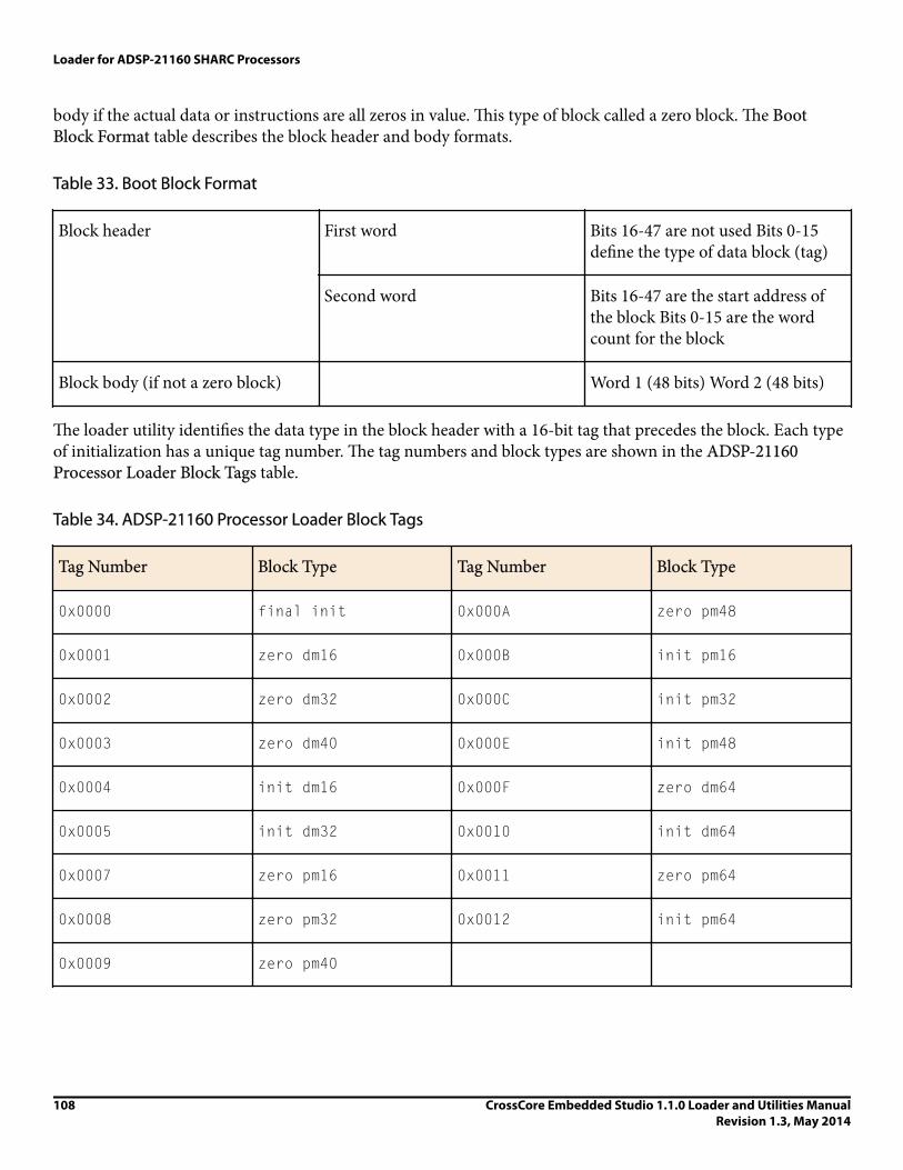
body if the actual data or instructions are all zeros in value. This type of block called a zero block. The BootBlock Format table describes the block header and body formats.
Table 33. Boot Block Format
Block header First word Bits 16-47 are not used Bits 0-15define the type of data block (tag)
Second word Bits 16-47 are the start address ofthe block Bits 0-15 are the wordcount for the block
Block body (if not a zero block) Word 1 (48 bits) Word 2 (48 bits)
The loader utility identifies the data type in the block header with a 16-bit tag that precedes the block. Each typeof initialization has a unique tag number. The tag numbers and block types are shown in the ADSP-21160Processor Loader Block Tags table.
Table 34. ADSP-21160 Processor Loader Block Tags
Tag Number Block Type Tag Number Block Type
0x0000 final init 0x000A zero pm48
0x0001 zero dm16 0x000B init pm16
0x0002 zero dm32 0x000C init pm32
0x0003 zero dm40 0x000E init pm48
0x0004 init dm16 0x000F zero dm64
0x0005 init dm32 0x0010 init dm64
0x0007 zero pm16 0x0011 zero pm64
0x0008 zero pm32 0x0012 init pm64
0x0009 zero pm40
Loader for ADSP-21160 SHARC Processors
108 CrossCore Embedded Studio 1.1.0 Loader and Utilities ManualRevision 1.3, May 2014

The kernel enables the boot port (external or link) to read the block header. After reading information from theblock header, the kernel places the body of the block in the appropriate place in memory if the block has a blockbody, or initializes in the appropriate place with zero values in the memory if the block is a zero block.
The final section, which is identified by a tag of 0x0, is called the final initialization section. This section has self-modifying code that, when executed, facilitates a DMA over the kernel, replacing it with user application codethat actually belongs in that space at run time. The final initialization code also takes care of interrupts andreturns the processor registers, such as SYSCON and DMAC orLCTL, to their default values.
When the loader utility detects the final initialization tag, it reads the next 48-bit word. This word indicates theinstruction to load into the 48-bit Px register after the boot kernel finishes initializing memory.
The boot kernel requires that the interrupt, external port (or link port address, depending on the boot mode)contains an RTI instruction. This RTI is inserted automatically by the loader utility to guarantee that the kernelexecutes from the reset vector, once the DMA that overwrites the kernel is complete. A last remnant of the kernelcode is left at the reset vector location to replace the RTI with the user's intended code. Because of this last kernelremnant, user application code should not use the first location of the reset vector. This first location should be aNOP or IDLE instruction. The kernel automatically completes, and the program controller begins sequencing theuser application code at the second location in the processor reset vector space.
When the boot process is complete, the processor automatically executes the user application code. The onlyremaining evidence of the boot kernel is at the first location of the interrupt vector. Almost no memory issacrificed to the boot code.
Boot Kernel Modificatio and Loader IssuesSome systems require boot kernel customization. The operation of other tools (such as the C/C++ compiler) isinfluenced by whether the boot kernel is used.
When producing a boot-loadable file, the loader utility reads a processor executable file and uses information init to initialize the memory. However, the loader utility cannot determine how the processor SYSCON and WAITregisters are to be configured for external memory loading in the system.
If you modify the boot kernel by inserting values for your system, you must rebuild it before generating theboot-loadable file. The boot kernel contains default values for SYSCON. The initialization code can be found in thecomments in the boot kernel source file.
After modifying the boot kernel source file, rebuild the boot kernel (.dxe) file. Do this from the IDE (refer toonline help for details), or rebuild the boot kernel file from the command line.
iNote:
Specify the name of the modified kernel executable in the Kernel file (-l) field on the CrossCore SHARCLoader > General page of the Tool Settings dialog box.
If you modify the boot kernel for EPROM, host, or link boot modes, ensure that the seg_ldr memory segmentis defined in the .ldf file. Refer to the source of the segment in the .ldf file located in the <install_path>/SHARC/ldr directory.
Loader for ADSP-21160 SHARC Processors
CrossCore Embedded Studio 1.1.0 Loader and Utilities ManualRevision 1.3, May 2014
109

The loader utility generates a warning when vector address 0x40004 does not contain NOP or IDLE. Because theboot kernel uses this address for the first location of the reset vector during the boot-load process, avoid placingcode at this address. When using any of the processor's power-up boot modes, ensure that the address does notcontain a critical instruction. Because the address is not executed during the booting sequence, place a NOP orIDLE instruction at this location.
The boot kernel project can be rebuilt from the IDE. The command-line can also be used to rebuild variousdefault boot kernels for the processors.
EPROM Booting. The default boot kernel source file for the ADSP-21161 EPROM booting is 161_prom.asm.Copy this file to my_prom.asm and modify it to suit your system. Then use the following commands to rebuildthe boot kernel:
easm21k -21161 my_prom.asm
or
easm21k -proc ADSP-21161 my_prom.asm
linker -T 161_ldr.ldf my_prom.doj
Host Booting. The default boot kernel source file for the ADSP-21161 host booting is 161_host.asm. Copy thisfile to my_host.asm and modify it to suit your system. Then use the following commands to rebuild the bootkernel:
easm21k -21161 my_host.asm
or
easm21k -proc ADSP-21161 my_host.asm
linker -T 161_ldr.ldf my_host.doj
Link Port Booting. The default boot kernel source file for the ADSP-21160 link port booting is 161_link.asm.Copy this file to my_link.asm and modify it to suit your system. Then use the following commands to rebuildthe boot kernel:
easm21k -21161 my_link.asm
or
easm21k -proc ADSP-21161 my_link.asm
linker -T 161_ldr.ldf my_link.doj
Rebuilding Boot Kernels
To rebuild the PROM boot kernel for the ADSP-21160 processors, use these commands:
easm21k -21160 my_prom.asm
or
easm21k -proc ADSP-21160 my_prom.asm
linker -T 160_ldr.ldf my_prom.doj
Loader for ADSP-21160 SHARC Processors
110 CrossCore Embedded Studio 1.1.0 Loader and Utilities ManualRevision 1.3, May 2014
ADSP-21160 Interrupt Vector TableIf an SHARC processor is booted from an external source (EPROM, host, or another SHARC processor), theinterrupt vector table is located in internal memory. If, however, the processor is not booted and executes from external memory, the vector table must be located in external memory.
The IIVT bit of the SYSCON control register can be used to override the boot mode in determining where theinterrupt vector table is located. If the processor is not booted (no-boot mode), setting IIVT to 1 selects aninternal vector table, and setting IIVT to 0 selects an external vector table. If the processor is booted from anexternal source (any mode other than no-boot mode), IIVT has no effect. The IIVT default initialization value is0.
Refer to EE-189: Link Port Tips and Tricks for ADSP-2116x on the Analog Devices Web site for moreinformation.
ADSP-21160 Multi-Application (Multi-DXE) ManagementCurrently, the loader utility generates single-processor loader files for host and link port boot modes. As a result,the loader utility supports multiprocessor EPROM boot mode only. The application code must be modified for amultiprocessor system boot in host and link port modes.
The loader utility can produce boot-loadable files that permit the SHARC processors in a multiprocessor systemto boot from a single EPROM. In such a system, the BMS signals from each SHARC processor are OR'ed togetherto drive the chip select pin of the EPROM. Each processor boots in turn, according to its priority. When the lastprocessor finishes booting, it must inform the processors to begin program execution.
Besides taking turns when booting, EPROM boot of multiple processors is similar to a single-processor EPROMboot.
When booting a multiprocessor system through a single EPROM:
• Connect all BMS pins to EPROM.• Processor with ID# of 1 boots first. The other processors follow.• The EPROM boot kernel accepts multiple .dxe files and reads the ID field inSYSTAT to determine which area
of EPROM to read.• All processors require a software flag or hardware signal (FLAG pins) to indicate that booting is complete.
When booting a multiprocessor system through an external port:
• The host can use the host interface.• A SHARC processor that is EPROM-, host-, or link-booted can boot the other processors through the external
port (host boot mode).
For multiprocessor EPROM booting, select the CrossCore SHARC Loader > Multiprocessor page of the ToolSettings dialog box or specify the -id1exe= switch on the loader command line. These options specify theexecutable file targeted for a specific processor.
Do not use the -id1exe= switch to EPROM-boot a single processor whose ID is 0. Instead, name the executablefile on the command line without a switch. For a single processor with ID=1, use the -id1exe= switch.
Loader for ADSP-21160 SHARC Processors
CrossCore Embedded Studio 1.1.0 Loader and Utilities ManualRevision 1.3, May 2014
111

ADSP-21160 Processor ID NumbersA single-processor system requires only one input (.dxe) file without any prefix and suffix to the input file name,for example:
elfloader -proc ADSP-21160 -bprom Input.dxe
A multiprocessor system requires a distinct processor ID number for each input file on the command line. Aprocessor ID is provided via the -id#exe=filename.dxe switch, where # is 0 to 6.
In the following example, the loader utility processes the input file Input1.dxe for the processor with an ID of 1and the input file Input2.dxe for the processor with an ID of 2.
elfloader -proc ADSP-21160 -bprom -id1exe=Input1.dxe -id2exe=Input2.dxe
If the executable for the # processor is identical to the executable of the N processor, the output loader filecontains only one copy of the code from the input file.
elfloader -proc ADSP-21160 -bprom -id1exe=Input.dxe -id2ref=1
The loader utility points the id(2)exe loader jump table entry to the id(1)exe image, effectively reducing thesize of the loader file.
Processor Loader GuideLoader utility operations depend on the loader properties, which control how the utility processes executablefiles. You select features, such as boot modes, boot kernels, and output file formats via the properties. Theproperties are specified on the loader utility's command line or the Tool Settings dialog box in the IDE(CrossCore Blackfin Loader pages). The default loader settings for a selected processor are preset in the IDE.
iNote:
The IDE’s Tool Settings correspond to switches displayed on the command line.
For detailed information about the processor loader properties page, refer to the online help.
These sections describe how to produce a bootable loader (.ldr) file:
• Loader Command Line for ADSP-21160 Processors• CCES Loader Interface for ADSP-21160 Processors
Loader Command Line for ProcessorsThe loader utility uses the following command-line syntax for the ADSP-21160 SHARC processors.
elfloader inputfile -proc part_number -switch [-switch]
where:
• inputfile - Name of the executable (.dxe) file to be processed into a single boot-loadable file. An input filename can include the drive and directory. Enclose long file names within straight quotes, "long file name".
• -proc part_number - Part number of the processor (for example, -proc ADSP-21160) for which the loadablefile is built. The -proc switch is mandatory.
Loader for ADSP-21160 SHARC Processors
112 CrossCore Embedded Studio 1.1.0 Loader and Utilities ManualRevision 1.3, May 2014

• -switch - One or more optional switches to process. Switches select operations and boot modes for the loaderutility. A list of all switches and their descriptions appear in Loader Command-Line Switches for ADSP-21160Processors.
iNote:
Command-line switches are not case-sensitive and placed on the command line in any order.
The following command line,
elfloader p0.dxe -bprom -fhex -l 160_prom.dxe -proc ADSP-21160
runs the loader utility with:
• p0.dxe - Identifies the executable file to process into a boot-loadable file. The absence of the -o switch causesthe output file name to default to p0.ldr.
• -bprom - Specifies EPROM booting as the boot type for the boot-loadable file.• -fhex - Specifies Intel hex-32 format for the boot-loadable file.• -l 160_prom.exe - Specifies 160_prom.exe as the boot kernel file to be used in the boot-loadable file.• -proc ADSP-21160 - Identifies the processor model as ADSP-21160.
Loader Command-Line Switches for ProcessorsThe Loader Command-Line Switches table is a summary of the loader switches for the ADSP-21160 processors.
Table 35. Loader Command-Line Switches
Switch Description
-bprom
-bhost
-blink
-bJTAG
Specifies the boot mode. The -b switch directs the loader utility toprepare a boot-loadable file for the specified boot mode. Validboot modes include PROM, host, and link.
If -b does not appear on the command line, the default is -bprom.To use a custom boot kernel, the boot type selected with the -bswitch must correspond to the boot kernel selected with the -lswitch. Otherwise, the loader utility automatically selects a defaultboot kernel based on the selected boot type (see ADSP-21160Boot Kernels).
-e filename Except shared memory. The -e switch omits the specified sharedmemory (.sm) file from the output loader file. Use this option toomit the shared parts of the executable file intended to boot amultiprocessor system.
To omit multiple.sm files, repeat the switch and parametermultiple times on the command line. For example, to omit twofiles, use: -e fileA.sm -e fileB.sm.
Loader for ADSP-21160 SHARC Processors
CrossCore Embedded Studio 1.1.0 Loader and Utilities ManualRevision 1.3, May 2014
113

Switch Description
In most cases, it is not necessary to use the -e switch: the loaderutility processes the .sm files efficiently-includes a single copy ofthe code and data from each .sm file in a loader file.
-fhex
-fASCII
-fbinary
-finclude
-fS1
-fS2
-fS3
Specifies the format of the boot-loadable file (Intel hex-32, ASCII,S1, S2, S3, binary, or include). If the -f switch does not appear onthe command line, the default boot file format is Intel hex-32 forPROM, and ASCII for host or link.
Available formats depend on the boot type selection (-b switch):
• For PROM boot type, select a hex, ASCII, S1, S2, S3, or includeformat.
• For host or link boot type, select an ASCII, binary, or includeformat.
-h
or
-help
Command-line help. Outputs a list of the command-line switchesto standard out and exits. Type elfloader -proc ADSP-21xxx-h, where xxx is 160 to obtain help for SHARC processors. Bydefault, the -h switch alone provides help for the loader driver.
-id#exe=filename Specifies the processor ID. The -id#exe= switch directs the loaderutility to use the processor ID (#) for the correspondingexecutable file (filename parameter) when producing a boot-loadable file for a multiprocessor system. This switch is used toproduce a boot-loadable file that boots multiple processors from asingle EPROM. Valid values for # are 1, 2, 3, 4, 5, and 6.
Do not use this switch for single-processor systems. For single-processor systems, use filename as a parameter without a switch.For more information, refer to ADSP-21160 Processor IDNumbers.
-id#ref=N Points the processor ID (#) loader jump table entry to the ID (N)image. If the executable file for the (#) processor is identical to theexecutable of the (N) processor, the switch can be used to set thePROM start address of the processor with ID of # to be the sameas for the processor with ID of N. This effectively reduces the sizeof the loader file by providing a single copy of an executable totwo or more processors in a multiprocessor system. For moreinformation, refer to ADSP-21160 Processor ID Numbers.
Loader for ADSP-21160 SHARC Processors
114 CrossCore Embedded Studio 1.1.0 Loader and Utilities ManualRevision 1.3, May 2014

Switch Description
-l kernelfile Directs the loader utility to use the specified kernelfile as theboot-loading routine in the output boot-loadable file. The bootkernel selected with this switch must correspond to the boot typeselected with the -b switch.
If the -l switch does not appear on the command line, the loadersearches for a default boot kernel file. Based on the boot type (-bswitch), the loader utility searches in the processor-specific loaderdirectory for the boot kernel file as described in ADSP-21160Boot Kernels.
-o filename Directs the loader utility to use the specified filename as thename for the loader output file. If not specified, the default nameis inputfile.ldr.
-p address PROM start address. Places the boot-loadable file at the specifiedaddress in the EPROM.
If the -p switch does not appear on the command line, the loaderutility starts the EPROM file at address 0x0; this EPROM addresscorresponds to 0x800000 on ADSP-21160 processors.
-proc processor Specifies the processor. This a mandatory switch.
-si-revision [none|any|x.x] Sets revision for the build, with x.x being the revision number forthe processor hardware. If -si-revision is not used, the target isa default revision from the supported revisions.
-t # (Host boot only) Specifies timeout cycles; for example, -t100.Limits the number of cycles that the processor spends initializing external memory with zeros. Valid timeout values (#) range from3 to 32765 cycles; 32765 is the default. The # is directly related tothe number of cycles the processor locks the bus for boot-loading,instructing the processor to lock the bus for no more than twotimes the timeout number of cycles. When working with a fasthost that cannot tolerate being locked out of the bus, use arelatively small timeout value.
-use32bitTagsforExternalMemoryBlocks
Directs the loader utility to treat the external memory sections as32-bit sections, as specified in the .ldf file and does not packthem into 48-bit sections before processing. This option is useful
Loader for ADSP-21160 SHARC Processors
CrossCore Embedded Studio 1.1.0 Loader and Utilities ManualRevision 1.3, May 2014
115

Switch Description
if the external memory sections are packed by the linker and donot need the loader utility to pack them again.
-v Outputs verbose loader utility messages and status information asthe utility processes files.
-version Directs the loader utility to show its version information. Typeelfloader -version to display the version of the loader drive.Add the -proc switch, for example, elfloader -procADSP-21160 -version to display version information of bothloader drive and SHARC loader utility.
CCES Loader Interface for ProcessorsOnce a project is created in the CrossCore Embedded Studio IDE, you can change the project's output (artifact)type.
The IDE invokes the elfloader.exe utility to build the output loader file. To modify the default loaderproperties, use the project's Tool Settings dialog box. The controls on the pages correspond to the loadercommand-line switches and parameters (see Loader Command-Line Switches for ADSP-21160 Processors).
The loader pages (also called loader properties pages) show the default loader settings for the project's targetprocessor. Refer to the CCES online help for information about the loader interface.
The CCES splitter interface for the ADSP-21160 processors is documented in the Splitter for SHARC Processorschapter.
Loader for ADSP-21160 SHARC Processors
116 CrossCore Embedded Studio 1.1.0 Loader and Utilities ManualRevision 1.3, May 2014

8Loader for ADSP-21161 SHARC Processors
This chapter explains how the loader utility (elfloader.exe) is used to convert executable (.dxe) files intoboot-loadable files for the ADSP-21161 SHARC processors.
Refer to the Introduction chapter for the loader utility overview; the introductory material applies to allprocessor families. Refer to the Loader for ADSP-21160 SHARC Processors chapter for information about theADSP-21160 processors. Refer to the Loader for ADSP-2126x/2136x/2137x/214xx SHARC Processors chapterfor information about the ADSP-2126x, ADSP-2136x, ADSP-2137x, ADSP-2146x, ADSP-2147x, andADSP-2148x processors.
Loader operations specific to the SHARC processors are detailed in the following sections.
• ADSP-21161 Processor Booting
Provides general information about various boot modes, including information about boot kernels.• ADSP-21161 Processor Loader Guide
Provides reference information about the loader utility's graphical user interface, command-line syntax, andswitches.
ADSP-21161 Processor BootingThe processors support five boot modes: EPROM, host, link port, SPI port, and no-boot (see tables ADSP-21161Boot Mode Pins and ADSP-21161 Boot Mode Pin States in Boot Mode Selection). Boot-loadable files for thesemodes pack boot data into words of appropriate widths and use an appropriate DMA channel of the processor'sDMA controller to boot-load the words.
• When booting from an EPROM through the external port, the ADSP-21161 processor reads boot data from an8-bit external EPROM.
• When booting from a host processor through the external port, the ADSP-21161 processor accepts boot datafrom 8- or 16-bit host microprocessor.
• When booting through the link port, the ADSP-21161 processor receives boot data through the link port as 4-bit wide data in link buffer 4.
Loader for ADSP-21161 SHARC Processors
CrossCore Embedded Studio 1.1.0 Loader and Utilities ManualRevision 1.3, May 2014
117

• When booting through the SPI port, the ADSP-21161 processor uses DMA channel 8 of the IO processor totransfer instructions to internal memory. In this boot mode, the processor receives data in the SPIRx register.
• In no-boot mode, the ADSP-21161 processors begin executing instructions from external memory.
Software developers who use the loader utility should be familiar with the following operations:
• Power-Up Booting Process• Boot Mode Selection• ADSP-21161 Processor Boot Modes• ADSP-21161 Processor Boot Kernels• Boot Kernel Modification and Loader Issues• ADSP-21161 Processor Interrupt Vector Table• ADSP-21161 Multi-Application (Multi-DXE) Management
Power-Up Booting ProcessThe processors include a hardware feature that boot-loads a small, 256-instruction program into the processor'sinternal memory after power-up or after the chip reset. These instructions come from a program called boot kernel. When executed, the boot kernel facilitates booting of user application code. The combination of the bootkernel and application code comprises the boot-loadable (.ldr) file.
At power-up, after the chip reset, the booting process includes the following steps.
1. Based on the boot mode, an appropriate DMA channel is automatically configured for a 256-instructiontransfer. This transfer boot-loads the boot kernel program into the processor memory.
2. The boot kernel runs and loads the application executable code and data.3. The boot kernel overwrites itself with the first 256 words of the application at the end of the booting process.
After that, the application executable code starts running.
The boot mode selection directs the system to prepare the appropriate boot kernel.
Boot Mode SelectionThe state of the LBOOT, EBOOT, and BMS pins selects the processor's boot mode. The ADSP-21161 Boot Mode Pinsand ADSP-21161 Boot Mode Pin States tables show how the pin states correspond to the modes.
Table 36. ADSP-21161 Boot Mode Pins
Pin Type Description
EBOOT I EPROM boot - when EBOOT is high, the processor boot-loadsfrom an 8-bit EPROM through the processor's external port.When EBOOT is low, the LBOOT and BMS pins determine bootingmode.
Loader for ADSP-21161 SHARC Processors
118 CrossCore Embedded Studio 1.1.0 Loader and Utilities ManualRevision 1.3, May 2014

Pin Type Description
LBOOT I Link port boot - when LBOOT is high and EBOOT is low, theprocessor boots from another SHARC processor through theprocessor's link port. When LBOOT is low and EBOOT is low, theprocessor boots from a host processor through the processor'sexternal port.
BMS I/O/T7 Boot memory select - when boot-loading from EPROM (EBOOT=1and LBOOT=0), the pin is an output and serves as the chip selectfor the EPROM. In a multiprocessor system, BMS is output by thebus master. When host-booting, link-booting, or SPI-booting(EBOOT=0), BMS is an input and must be high.
Table 37. ADSP-21161 Boot Mode Pin States
EBOOT LBOOT BMS Booting Mode
1 0 Output EPROM (connects BMS to EPROM chipselect)
0 0 1 (Input) Host processor
0 1 1 (Input) Link port
0 1 0 (Input) Serial port (SPI)
0 0 0 (Input) No-boot (processor executes from externalmemory)
ADSP-21161 Processor Boot ModesThe processors support these boot modes: EPROM, host, link, and SPI. The following section describe each ofthe modes.
• EPROM Boot Mode• Host Boot Mode• Link Port Boot Mode• SPI Port Boot Mode• No-Boot Mode
7 Three-statable in EPROM boot mode (when BMS is an output).
Loader for ADSP-21161 SHARC Processors
CrossCore Embedded Studio 1.1.0 Loader and Utilities ManualRevision 1.3, May 2014
119

iNote:
For multiprocessor booting, refer to ADSP-21161 Multi-Application (Multi-DXE) Management.
EPROM Boot ModeEPROM boot via the external port is selected when the EBOOT input is high and the LBOOT input is low. Thesesettings cause the BMS pin to become an output, serving as chip select for the EPROM.
The DMAC10 control register is initialized for booting packing boot data into 48-bit instructions. EPROM bootmode uses channel 10 of the IO processor's DMA controller to transfer the instructions to internal memory. ForEPROM booting, the processor reads data from an 8-bit external EPROM.
After the boot process loads 256 words into memory locations 0x40000 through 0x400FF, the processor beginsto execute instructions. Because most processor programs require more than 256 words of instructions andinitialization data, the 256 words typically serve as a loading routine for the application. CrossCore EmbeddedStudio includes loading routines (boot kernels) that can load entire programs; see ADSP-21161 Processor BootKernels for more information.
Refer to the ADSP-21161 SHARC DSP Hardware Reference for detailed information on DMA and systemconfigurations.
iNote:
Be aware that DMA channel differences between the ADSP-21161 and previous SHARC processorsaccount for boot differences. Even with these differences, the ADSP-21161 processor supports the sameboot capability and configuration as previous SHARC processors. The DMACx register default values differbecause the ADSP-21161 processor has additional parameters and different DMA channel assignments.EPROM boot mode uses EPB0, DMA channel 10. Similar to previous SHARC processors, theADSP-21161 processor boots from DATA23—16.
The processor determines the booting mode at reset from the EBOOT, LBOOT, andBMS pin inputs. When EBOOT=1and LBOOT=0, the processor boots from an EPROM through the external port and uses BMS as the memory selectoutput. For information on boot mode selection, see the boot memory select pin descriptions in tablesADSP-21161 Boot Mode Pins and ADSP-21161 Boot Mode Pin States (in Boot Mode Selection).
iNote:
When using any of the power-up boot modes, address 0x40004 should not contain a valid instructionsince it is not executed during the booting sequence. Place a NOP or IDLE instruction at this location.
EPROM boot (boot space 8M x 8-bit) through the external port requires that an 8-bit wide boot EPROM beconnected to the processor data bus pins 23-16 (DATA23-16). The processor's lowest address pins should beconnected to the EPROM address lines. The EPROM's chip select should be connected to BMS, and its outputenable should be connected to RD.
In a multiprocessor system, the BMS output is driven by the ADSP-21161 processor bus master only. This allowsthe wired OR of multiple BMS signals for a single common boot EPROM.
iNote:
Loader for ADSP-21161 SHARC Processors
120 CrossCore Embedded Studio 1.1.0 Loader and Utilities ManualRevision 1.3, May 2014

Systems can boot up to six ADSP-21161 processors from a single EPROM using the same code for eachprocessor or differing code for each processor.
During reset, the ACK line is internally pulled high with the equivalent of an internal 20K ohm resistor and isheld high with an internal keeper latch. It is not necessary to use an external pull-up resistor on the ACK lineduring booting or at any other time.
The RBWS and RBAM fields of theWAIT register are initialized to perform asynchronous access and generate seven wait states (8 cycles total) for the EPROM access in external memory space. Note that wait states defined forboot memory are applied to BMS asserted accesses.
The DMA Channel 10 Parameter Registers for EPROM Booting table shows how DMA channel 10 parameterregisters are initialized at reset. The count register (CEP0) is initialized to 0x0100 to transfer 256 words tointernal memory. The external count register (ECEP0), used when external addresses (BMS space) are generatedby the DMA controller, is initialized to 0x0600 (0x0100 words at six bytes per word). The DMAC10 controlregister is initialized to 0x00 0561.
Table 38. DMA Channel 10 Parameter Registers for EPROM Booting
Parameter Register Initialization Value
IIEP0 0x40000
IMEP0 Uninitialized (increment by 1 is automatic)
CEP0 0x100 (256-instruction words)
CPEP0 Uninitialized
GPEP0 Uninitialized
EIEP0 0x800000
EMEP0 Uninitialized (increment by 1 is automatic)
ECEP0 0x600 (256 words x 6 bytes/word)
The default value sets up external port transfers as follows:
• DEN = 1, external port enabled• MSWF = 0, LSB first• PMODE = 101, 8-bit to 48-bit packing, Master = 1• DTYPE = 1, three column data
The following sequence occurs at system start-up, when the processor RESET input goes inactive.
Loader for ADSP-21161 SHARC Processors
CrossCore Embedded Studio 1.1.0 Loader and Utilities ManualRevision 1.3, May 2014
121

1. The processor goes into an idle state, identical to that caused by the IDLE instruction. The program counter(PC) is set to address 0x40004.
2. The DMA parameter registers for channel 10 are initialized as shown in the DMA Channel 10 ParameterRegisters for EPROM Booting table.
3. The BMS pin becomes the boot EPROM chip select.4. 8-bit master mode DMA transfers from EPROM to the first internal memory address on the external port
data bus lines 23-16.5. The external address lines (ADDR23-0) start at 0x800000 and increment after each access.6. The RD strobe asserts as in a normal memory access with seven wait states (8 cycles).
The processor's DMA controller reads the 8-bit EPROM words, packs them into 48-bit instruction words, andtransfers them to internal memory until 256 words have been loaded. The EPROM is automatically selected bythe BMS pin; other memory select pins are disabled.
The master DMA internal and external count registers (CEP0)ECEP0/ decrement after each EPROM transfer.When both counters reach zero, the following wake-up sequence occurs:
1. DMA transfers stop.2. External port DMA channel 10 interrupt (EP0I) is activated.3. The BMS pin is deactivated, and normal external memory selects are activated.4. The processor vectors to the EP0I interrupt vector at 0x40050.
At this point, the processor has completed its boot and is executing instructions normally. The first instruction atthe EP0Iinterrupt vector location, address 0x40050, should be an RTI (return from interrupt). This processreturns execution to the reset routine at location 0x40005 where normal program execution can resume. Afterreaching this point, a program can write a different service routine at the EP0I vector location 0x40050.
Host Boot ModeThe processor can boot from a host processor through the external port. Host booting is selected when theEBOOTand LBOOT inputs are low and BMS is high. Configured for host booting, the processor enters the slave mode after reset and waits for the host to download the boot program.
The DMAC10 control register is initialized for booting, packing boot data into 48-bit instructions. Channel 10 ofthe IO processor's DMA controller is used to transfer instructions to internal memory. Processors accept datafrom 8- or 16-bit host microprocessor (or other external devices).
After the boot process loads 256 words into memory locations 0x40000 through 0x400FF, the processor beginsexecuting instructions. Because most processor programs require more than 256 words of instructions andinitialization data, the 256 words typically serve as a loading routine for the application. CrossCore EmbeddedStudio includes loading routines (boot kernels) that can load entire programs; refer to ADSP-21161 ProcessorBoot Kernels for more information.
Refer to the ADSP-21161 SHARC DSP Hardware Reference for detailed information on DMA and systemconfigurations.
Loader for ADSP-21161 SHARC Processors
122 CrossCore Embedded Studio 1.1.0 Loader and Utilities ManualRevision 1.3, May 2014

iNote:
DMA channel differences between the ADSP-21161 and previous SHARC family processors account forboot differences. Even with these differences, the ADSP-21161 processors support the same bootcapability and configuration as previous SHARC processors. The DMAC10 register default values differbecause the ADSP-21161 processor has additional parameters and different DMA channel assignments.Host boot mode uses EPB0, DMA channel 10.
The processor determines the boot mode at reset from the EBOOT, LBOOT, and BMS pin inputs. When EBOOT=0,LBOOT=0, and BMS=1, the processor boots from a host through the external port. Refer to tables ADSP-21161Boot Mode Pins and ADSP-21161 Boot Mode Pin States in Boot Mode Selection for boot mode selections.
When using any of the power-up boot modes, address 0x40004 should not contain a valid instruction. Because itis not executed during the boot sequence, place a NOP or IDLE instruction at this location.
During reset, the processor ACK line is internally pulled high with an equivalent 20K ohm resistor and is heldhigh with an internal keeper latch. It is not necessary to use an external pull-up resistor on the ACK line duringbooting or at any other time.
The DMA Channel 10 Parameter Register for Host Boot table shows how the DMA channel 10 parameterregisters are initialized at reset for host boot. The internal count register (CEP0) is initialized to 0x0100 totransfer 256 words to internal memory. The DMAC10 control register is initialized to 0000 0161.
Table 39. DMA Channel 10 Parameter Register for Host Boot
Parameter Register Initialization Value
IIEP0 0x0004 0000
IMEP0 Uninitialized (increment by 1 is automatic)
CEP0 0x0100 (256-instruction words)
CPEP0 Uninitialized
GPEP0 Uninitialized
EIEP0 Uninitialized
EMEP0 Uninitialized
ECEP0 Uninitialized
The default value sets up external port transfers as follows:
• DEN = 1, external port enabled
Loader for ADSP-21161 SHARC Processors
CrossCore Embedded Studio 1.1.0 Loader and Utilities ManualRevision 1.3, May 2014
123

• MSWF = 0, LSB first• PMODE = 101, 8-bit to 48-bit packing• DTYPE = 1, three column data
At system start-up, when the processor RESET input goes inactive, the following sequence occurs.
1. The processor goes into an idle state, identical to that caused by the IDLE instruction. The program counter(PC) is set to address 0x40004.
2. The DMA parameter registers for channel 10 are initialized as shown in the DMA Channel 10 ParameterRegister for Host Boot table.
3. The host uses HBR and CS to arbitrate for the bus.4. The host can write to SYSCON (if HBG and READY are returned) to change boot width from default.5. The host writes boot information to external port buffer 0.
The slave DMA internal count register (CEP0) decrements after each transfer. When CEP0 reaches zero, thefollowing wake-up sequence occurs:
1. The DMA transfers stop.2. The external port DMA channel 10 interrupt (EP0I) is activated.3. The processor vectors to the EP0I interrupt vector at 0x40050.
At this point, the processor has completed its boot mode and is executing instructions normally. The firstinstruction at the EP0Iinterrupt vector location, address 0x40050, should be an RTI (return from interrupt).This process returns execution to the reset routine at location 0x40005 where normal program execution canresume. After reaching this point, a program can write a different service routine at the EP0I vector location0x40050.
Link Port Boot ModeLink port boot uses DMA channel 8 of the IO processor to transfer instructions to internal memory. In this bootmode, the processor receives 4-bit wide data in link buffer 0.
After the boot process loads 256 words into memory locations 0x40000 through 0x400FF, the processor beginsto execute instructions. Because most processor programs require more than 256 words of instructions andinitialization data, the 256 words typically serve as a loading routine for the application. CrossCore EmbeddedStudio includes loading routines (boot kernels) that load an entire program through the selected port; refer to ADSP-21161 Processor Boot Kernels for more information.
Refer to the ADSP-21161 SHARC DSP Hardware Reference for detailed information on DMA and systemconfigurations.
iNote:
DMA channel differences between the ADSP-21161 and previous SHARC family processors account forboot differences. Even with these differences, the ADSP-21161 processors support the same bootcapabilities and configuration as the previous SHARC processors.
Loader for ADSP-21161 SHARC Processors
124 CrossCore Embedded Studio 1.1.0 Loader and Utilities ManualRevision 1.3, May 2014

The processor determines the boot mode at reset from the EBOOT, LBOOT and BMS pin inputs. When EBOOT=0,LBOOT=1, and BMS=1, the processor boots through the link port. For information on boot mode selection, seetables ADSP-21161 Boot Mode Pins and ADSP-21161 Boot Mode Pin States in Boot Mode Selection.
iNote:
When using any of the power-up booting modes, address 0x40004 should not contain a valid instruction.Because it is not executed during the boot sequence, place a NOP or IDLE instruction at this location.
In link port boot, the processor gets boot data from another processor link port or 4-bit wide external deviceafter system power-up.
The external device must provide a clock signal to the link port assigned to link buffer 0. The clock can be any frequency up to the processor clock frequency. The clock falling edges strobe the data into the link port. Themost significant 4-bit nibble of the 48-bit instruction must be downloaded first.
The DMA Channel 8 Parameter Register for Link Port Boot table shows how the DMA channel 8 parameterregisters are initialized at reset. The count register (CLB0) is initialized to 0x0100 to transfer 256 words tointernal memory. The LCTL register is overridden during link port boot to allow link buffer 0 to receive 48-bitdata.
Table 40. DMA Channel 8 Parameter Register for Link Port Boot
Parameter Register Initialization Value
IILB0 0x0004 0000
IMLB0 Uninitialized (increment by 1 is automatic)
CLB0 0x0100 (256-instruction words)
CPLB0 Uninitialized
GPLB0 Uninitialized
In systems where multiple processors are not connected by the parallel external bus, booting can beaccomplished from a single source through the link ports. To simultaneously boot all the processors, make aparallel common connection to link buffer 0 on each of the processors. If a daisy chain connection existsbetween the processors' link ports, each processor can boot the next processor in turn. Link buffer 0 must alwaysbe used for booting.
SPI Port Boot ModeSerial peripheral interface (SPI) port booting uses DMA channel 8 of the IO processor to transfer instructions tointernal memory. In this boot mode, the processor receives 8-bit wide data in the SPIRx register.
Loader for ADSP-21161 SHARC Processors
CrossCore Embedded Studio 1.1.0 Loader and Utilities ManualRevision 1.3, May 2014
125

During the boot process, the program loads 256 words into memory locations 0x40000 through 0x400FF. Theprocessor subsequently begins executing instructions. Because most processor programs require more than 256words of instructions and initialization data, the 256 words typically serve as a loading routine for theapplication. CrossCore Embedded Studio includes loading routines (boot kernels) which load an entire programthrough the selected port. See ADSP-21161 Processor Boot Kernels for more information.
Refer to the ADSP-21161 SHARC DSP Hardware Reference for detailed information on DMA and systemconfigurations.
The processor determines the boot mode at reset from the EBOOT, LBOOT, and BMS pin inputs. When EBOOT=0,LBOOT=1, and BMS=0, the processor boots through its SPI port. For information on the boot mode selection, seetables ADSP-21161 Boot Mode Pins and ADSP-21161 Boot Mode Pin States in Boot Mode Selection.
iNote:
When using any of the power-up booting modes, address 0x40004 should not contain a valid instruction.Because it is not executed during the boot sequence, place a NOP or IDLE instruction placed at thislocation.
For SPI port boot, the processor gets boot data after system power-up from another processor's SPI port oranother SPI compatible device.
The DMA Channel 8 Parameter Register for SPI Port Boot table shows how the DMA channel 8 parameterregisters are initialized at reset. The SPI control register (SPICTL) is configured to 0x0A001F81 upon reset duringSPI boot.
This configuration sets up the SPIRx register for 32-bit serial transfers. The SPIRx DMA channel 8 parameterregisters are configured to DMA in 0x180 32-bit words into internal memory normal word address spacestarting at 0x40000. Once the 32-bit DMA transfer completes, the data is accessed as 3 column, 48-bitinstructions. The processor executes a 256 word (0x100) boot kernel upon completion of the 32-bit, 0x180 wordDMA.
For 16-bit SPI hosts, two words are shifted into the 32-bit receive shift register before a DMA transfer to internalmemory occurs. For 8-bit SPI hosts, four words are shifted into the 32-bit receive shift register before a DMAtransfer to internal memory occurs.
Table 41. DMA Channel 8 Parameter Register for SPI Port Boot
Parameter Register Initialization Value
IISRX 0x0004 0000
IMSRX Uninitialized (increment by 1 is automatic)
CSRX 0x0180 (256-instruction words)
GPSRX Uninitialized
Loader for ADSP-21161 SHARC Processors
126 CrossCore Embedded Studio 1.1.0 Loader and Utilities ManualRevision 1.3, May 2014

No-Boot ModeNo-boot mode causes the processor to start fetching and executing instructions at address 0x200004 in externalmemory space. In no-boot mode, the processor does not boot-load and all DMA control and parameter registersare set to their default initialization values. The loader utility does not produce the code for no-boot execution.
ADSP-21161 Processor Boot KernelsThe boot-loading process starts with a transfer of the boot kernel program into the processor memory. The bootkernel sets up the processor and loads boot data. After the boot kernel finishes initializing the rest of the system,the boot kernel loads boot data over itself with a final DMA transfer.
Four boot kernels are shipped with CrossCore Embedded Studio; refer to the Default Boot Kernel Files table.
Table 42. Default Boot Kernel Files
PROM Booting Link Booting Host Booting SPI Booting
161_PROM.dxe 161_LINK.dxe 161_HOST.dxe 161_SPI.dxe
Boot kernels are loaded at processor reset into the seg_ldr memory segment, which is defined in the161_ldr.ldf. The file is stored in the <install_path>/SHARC/ldr directory.
Processor Boot StreamsThe loader utility produces the boot stream in blocks and inserts header words at the beginning of data blocks inthe loader (.ldr) file. The boot kernel uses header words to properly place data and instruction blocks intoprocessor memory. The header format for PROM, host, and link boot-loader files is as follows.
0x00000000DDDD
0xAAAAAAAALLLL
In the above example, D is a data block type tag, A is a block start address, and L is a block word length.
For single-processor systems, the data block header has three 32-bit words in SPI boot mode, as follows.
0xLLLLLLLL First word. Data word length or data word count of the data block.
0xAAAAAAAA Second word. Data block start address.
0x000000DD Third word. Tag of data block type.
The boot kernel examines the tag to determine the type of data or instruction being loaded. The ADSP-21161NProcessor Block Tags table lists the ADSP-21161N processor block tags.
Loader for ADSP-21161 SHARC Processors
CrossCore Embedded Studio 1.1.0 Loader and Utilities ManualRevision 1.3, May 2014
127

Table 43. ADSP-21161N Processor Block Tags
Tag Number Block Type Tag Number Block Type
0x0000 final init 0x000E init pm48
0x0001 zero dm16 0x000F zero dm64
0x0002 zero dm32 0x0010 init dm64
0x0003 zero dm40 0x0012 init pm64
0x0004 init dm16 0x0013 init pm8 ext
0x0005 init dm32 0x0014 init pm16 ext
0x0007 zero pm16 0x0015 init pm32 ext
0x0008 zero pm32 0x0016 init pm48 ext
0x0009 zero pm40 0x0017 zero pm8 ext
0x000A zero pm48 0x0018 zero pm16 ext
0x000B init pm16 0x0019 zero pm32 ext
0x000C init pm32 0x001A zero pm48 ext
0x0011 zero pm64
Boot Kernel Modificatio and Loader IssuesSome systems require boot kernel customization. In addition, the operation of other tools (such as the C/C++compiler) is influenced by whether the loader utility is used.
If you do not specify a boot kernel file via the loader pages of the Tool Settings dialog box in the IDE (or via the -l kernelfile command-line switch), the loader utility places a default boot kernel in the loader output file (see ADSP-21161 Processor Boot Kernels)) based on the specified boot mode.
Rebuilding a Boot Kernel File
If you modify the boot kernel source (.asm) file by inserting correct values for your system, you must rebuild theboot kernel (.dxe) before generating the boot-loadable (.ldr) file. The boot kernel source file contains default
Loader for ADSP-21161 SHARC Processors
128 CrossCore Embedded Studio 1.1.0 Loader and Utilities ManualRevision 1.3, May 2014

values for the SYSCON register. The WAIT, SDCTL, and SDRDIV initialization code is in the boot kernel filecomments.
To Modify a boot kernel source file
1. Copy the applicable boot kernel source file (161_link.asm, 161_host.asm, 161_prom.asm, or161_spi.asm).
2. Apply the appropriate initializations of the SYSCON and WAIT registers.
After modifying the boot kernel source file, rebuild the boot kernel (.dxe) file. Do this from the IDE (refer toonline help for details), or rebuild the boot kernel file from the command line.
Rebuilding a Boot Kernel Using Command Lines
Rebuild a boot kernel using command lines as follows.
EPROM Boot. The default boot kernel source file for EPROM booting is 161_prom.asm. After copying thedefault file to my_prom.asm and modifying it to suit your system, use the following command lines to rebuild theboot kernel.
easm21k -proc ADSP-21161 my_prom.asm
linker -T 161_ldr.ldf my_prom.doj
Host Boot. The default boot kernel source file for host booting is 161_host.asm. After copying the default file tomy_host.asm and modifying it to suit your system, use the following command lines to rebuild the boot kernel.
easm21k -proc ADSP-21161 my_host.asm
linker -T 161_ldr.ldf my_host.doj
Link Boot. The default boot kernel source file for link booting is 161_link.asm. After copying the default file tomy_link.asm and modifying it to suit your system, use the following command lines to rebuild the boot kernel.
easm21k -proc ADSP-21161 my_link.asm
linker -T 161_ldr.ldf my_link.doj
SPI Boot. The default boot kernel source file for link booting is 161_SPI.asm. After copying the default file tomy_SPI.asm and modifying it to suit your system, use the following command lines to rebuild the boot kernel:
easm21k -proc ADSP-21161 my_SPI.asm
linker -T 161_ldr.ldf my_SPI.doj
Loader File Issues
If you modify the boot kernel for the EPROM, host, SPI, or link booting modes, ensure that the seg_ldrmemory segment is defined in the .ldf file. Refer to the source of this memory segment in the .ldf file locatedin the ldr directory of the of the target processor.
Because the loader utility uses the address of 0x40004 for the first location of the reset vector during the boot-load process, avoid placing code at this address. When using any of the processor's power-up boot modes, ensurethat this address does not contain a critical instruction. Because this address is not executed during the booting
Loader for ADSP-21161 SHARC Processors
CrossCore Embedded Studio 1.1.0 Loader and Utilities ManualRevision 1.3, May 2014
129

sequence, place a NOP or IDLE in this location. The loader utility generates a warning if the vector address0x40004 does not contain NOP or IDLE.
iNote:
When creating the loader file, specify the name of the customized boot kernel executable in the Kernel file(-l) field on the CrossCore SHARC Loader page of the Tool Settings dialog box.
ADSP-21161 Processor Interrupt Vector TableIf the processor is booted from an external source (EPROM, host, link port, or SPI), the interrupt vector table islocated in internal memory. If the processor is not booted and executes from external memory (no-boot mode),the vector table must be located in external memory.
The IIVT bit in the SYSCON control register can be used to override the booting mode in determining where theinterrupt vector table is located. If the processor is not booted (no-boot mode), setting IIVT to 1 selects aninternal vector table, and setting IIVT to zero selects an external vector table. If the processor is booted from anexternal source (any boot mode other than no-boot), IIVT has no effect. The default initialization value of IIVTis zero.
ADSP-21161 Multi-Application (Multi-DXE) ManagementCurrently, the loader utility generates single-processor loader files for host, link, and SPI port boot. The loaderutility supports multiprocessor EPROM boot only. The application code must be modified to properly set upmultiprocessor booting in host, link, and SPI port boot modes.
There are two methods by which a multiprocessor system can be booted:
• Boot From a Single EPROM• Sequential EPROM Boot
Regardless of the method, the processors perform the following steps.
1. Arbitrate for the bus2. Upon becoming bus master, DMA the 256-word boot stream3. Release the bus4. Execute the loaded instructions
Boot From a Single EPROMThe loader utility can produce boot-loadable files that permit SHARC processors in a multiprocessor system toboot from a single EPROM. The BMS signals from each processor may be wire ORed together to drive theEPROM's chip select pin. Each processor can boot in turn, according to its priority. When the last processor hasfinished booting, it must inform the other processors (which may be in the idle state) that program executioncan begin (if all processors are to begin executing instructions simultaneously).
Loader for ADSP-21161 SHARC Processors
130 CrossCore Embedded Studio 1.1.0 Loader and Utilities ManualRevision 1.3, May 2014

When multiple processors boot from a single EPROM, the processors can boot identical code or different codefrom the EPROM. If the processors load differing code, use a jump table in the loader file (based on processorID) to select the code for each processor.
Sequential EPROM BootSet the EBOOT pin of the processor with ID# of 1 high for EPROM booting. The other processors should beconfigured for host boot (EBOOT=0, LBOOT=0, and BMS=1), leaving them in the idle state at startup and allowingthe processor with ID=1 to become bus master and boot itself. Connect the BMS pin of processor #1 only to theEPROM's chip select pin. When processor #1 has finished booting, it can boot the remaining processors bywriting to their external port DMA buffer 0 (EPB0) via the multiprocessor memory space.
Processor ID NumbersA single-processor system requires only one input (.dxe) file without any prefix and suffix to the input file name,for example:
elfloader -proc ADSP-21161 -bprom Input.dxe
A multiprocessor system requires a distinct processor ID number for each input file on the command line. Aprocessor ID is provided via the -id#exe=filename.dxe switch, where # is 1 to 6.
In the following example, the loader utility processes the input file Input1.dxe for the processor with an ID of 1and the input file Input2.dxe for the processor with an ID of 2.
elfloader -proc ADSP-21161 -bprom -id1exe=Input1.dxe -id2exe=Input2.dxe
If the executable for the # processor is identical to the executable of the N processor, the output loader filecontains only one copy of the code from the input file, as directed by the command-line switch -id#ref=N usedin the example:
elfloader -proc ADSP-21161 -bprom -id1exe=Input.dxe -id2ref=1
where 2 is the processor ID, and 1 is another processor ID referenced by processor 2.
The loader utility points the id(2)exe loader jump table entry to the id(1)exe image, effectively reducing thesize of the loader file.
ADSP-21161 Processor Loader GuideLoader utility operations depend on the loader properties, which control how the utility processes executablefiles. You select features, such as boot modes, boot kernels, and output file formats via the properties. Theproperties are specified on the loader utility's command line or the Tool Settings dialog box in the IDE(CrossCore Blackfin Loader pages). The default loader settings for a selected processor are preset in the IDE.
iNote:
The IDE’s Tool Settings correspond to switches displayed on the command line.
These sections describe how to produce a bootable loader (.ldr) file:
Loader for ADSP-21161 SHARC Processors
CrossCore Embedded Studio 1.1.0 Loader and Utilities ManualRevision 1.3, May 2014
131
• Loader Command Line for ADSP-21161 Processors• CCES Loader Interface for ADSP-21161 Processors
Loader Command Line for ProcessorsThe loader utility uses the following command-line syntax for the ADSP-21161 SHARC processors.
elfloader inputfile -proc ADSP-21161 -switch [-switch]
where:
• inputfile - Name of the executable file (.dxe) to be processed into a single boot-loadable file. An input filename can include the drive and directory. Enclose long file names within straight quotes, "long file name".
• -proc ADSP-21161 - Part number of the processor for which the loadable file is built. The -proc switch ismandatory.
• -switch - One or more optional switches to process. Switches select operations and boot modes for the loaderutility. A list of all switches and their descriptions can be found in Loader Command-Line Switches forADSP-21161 Processors.
iNote:
Command-line switches are not case-sensitive and placed on the command line in any order.
Single-Processor Systems
The following command line,
elfloader Input.dxe -bSPI -proc ADSP-21161
runs the loader utility with:
• Input.dxe - Identifies the executable file to process into a boot-loadable file for a single-processor system.Note that the absence of the -o switch causes the output file name to default to Input.ldr.
• -bSPI - Specifies SPI port booting as the boot type for the boot-loadable file.• -proc ADSP-21161 - Specifies ADSP-21161 as the target processor.
Multiprocessor Systems
The following command line,
elfloader -proc ADSP-21161 -bprom -id1exe=Input1.dxe -id2exe=Input2.dxe
runs the loader utility with:
• -proc ADSP-21161 - Specifies ADSP-21161 as the target processor.• -bprom - Specifies EPROM booting as the boot type for the boot-loadable file.• -id1exe=Input1.dxe - Identifies Input1.dxe as the executable file to process into a boot-loadable file for a
processor with ID of 1 (see Processor ID Numbers)).• -id2exe=Input2.dxe - Identifies Input2.dxe. as the executable file to process into a boot-loadable file for a
processor with ID of 2 (see Processor ID Numbers)).
Loader for ADSP-21161 SHARC Processors
132 CrossCore Embedded Studio 1.1.0 Loader and Utilities ManualRevision 1.3, May 2014

Loader Command-Line Switches for ADSP-21161 ProcessorsThe ADSP-21161 Loader Command Line Switches table is a summary of the loader switches for theADSP-21161processors.
Table 44. ADSP-21161 Loader Command Line Switches
Switch Description
-bprom
-bhost
-blink
-bspi
Specifies the boot mode. The -b switch directs the loader utility toprepare a boot-loadable file for the specified boot mode. The validmodes (boot types) are PROM, host, link, and SPI. If the switchdoes not appear on the command line, the default is -bprom. Touse a custom boot kernel, the boot mode selected with the -bswitch must correspond with the boot kernel selected with the -lkernelfile switch. Otherwise, the loader utility automaticallyselects a default boot kernel based on the selected boot type (see ADSP-21161 Processor Boot Kernels).
-e filename Except shared memory. The -e switch omits the specified sharedmemory (.sm) file from the output loader file. Use this option toomit the shared parts of the executable file intended to boot amultiprocessor system.
To omit multiple .sm files, repeat the switch and its parametermultiple times on the command line. For example, to omit twofiles, use: -efileA.SM -efileB.SM.
In most cases, it is not necessary to use the -e switch: the loaderutility processes the .sm files efficiently (includes a single copy ofthe code and data from each .sm file in a loader file).
-fhex
-fASCII
-fbinary
-finclude
-fS1
-fS2
-fS3
Specifies the format of the boot-loadable file (Intel hex-32, ASCII,include, binary, S1, S2, and S3 (Motorola S-records). If the -fswitch does not appear on the command line, the default boot fileformat is hex for PROM, and ASCII for host, link, or SPI.
Available formats depend on the boot mode selection (-b switch):
• For a PROM boot, select a hex-32, S1, S2, S3, ASCII, or includeformat.
• For host or link boot, select an ASCII, binary, or include format.• For SPI boot, select an ASCII or binary format.
Loader for ADSP-21161 SHARC Processors
CrossCore Embedded Studio 1.1.0 Loader and Utilities ManualRevision 1.3, May 2014
133

Switch Description
-h
or
-help
Command-line help. Outputs the list of command-line switchesto standard output and exits. Combining the -h switch with -proc ADSP-21161; for example, elfloader -proc ADSP-21161-h, yields the loader syntax and switches for the ADSP-21161processors. By default, the -h switch alone provides help for theloader driver.
-hostwidth {8|16|32} Sets up the word width for the .ldr file. By default, the wordwidth for PROM and host is 8, for link is 16, and for SPI is 32. Thevalid word widths for the various boot modes are:
• PROM - 8 for hex or ASCII format, 8 or 16 for include format• host - 8 or 16 for ASCII or binary format, 16 for include format• link - 16 for ASCII, binary, or include format• SPI - 8, 16, or 32 for Intel hex 32 or ASCII format
-id#exe=filename Specifies the processor ID. The -id#exe= switch directs the loaderutility to use the processor ID (#) for the correspondingexecutable file (filename) when producing a boot-loadable filefor EPROM boot of a multiprocessor system. This switch is usedonly to produce a boot-loadable file that boots multipleprocessors from a single EPROM.
Valid values for # are 1, 2, 3, 4, 5, and 6.
Do not use this switch for single-processor systems. For single-processor systems, use filename as a parameter without a switch.For more information, refer to Processor ID Numbers.
-id#ref=N
Points the processor ID (#) loader jump table entry to the ID (N)image. If the executable file for the (#) processor is identical to theexecutable of the (N) processor, the switch can be used to set thePROM start address of the processor with ID of # to be the sameas for the processor with ID of N. This effectively reduces the sizeof the loader file by providing a single copy of an executable totwo or more processors in a multiprocessor system. For moreinformation, refer to Processor ID Numbers.
-l kernelfile Directs the loader utility to use the specified kernelfile as theboot-loading routine in the output boot-loadable file. The bootkernel selected with this switch must correspond to the bootmode selected with the -b switch.
Loader for ADSP-21161 SHARC Processors
134 CrossCore Embedded Studio 1.1.0 Loader and Utilities ManualRevision 1.3, May 2014

Switch Description
If the -l switch does not appear on the command line, the loaderutility searches for a default boot kernel file. Based on the bootmode (-b switch), the loader utility searches in the processor-specific loader directory for the boot kernel file as described in ADSP-21161 Processor Boot Kernels.
-o filename Directs the loader utility to use the specified filename as thename for the loader output file. If not specified, the default nameis inputfile.ldr.
-noZeroBlock The -noZeroBlock switch directs the loader utility not to buildzero blocks.
-p address Directs the loader utility to start the boot-loadable file at thespecified address in the EPROM. This EPROM addresscorresponds to 0x8000000 on the processor. If the -p switch doesnot appear on the command line, the loader utility starts theEPROM file at address 0x0.
-proc ADSP-21161 Specifies the processor. This is a mandatory switch.
-si-revision [none|any|x.x] Sets revision for the build, with x.x being the revision number forthe processor hardware. If -si-revision is not used, the target isa default revision from the supported revisions.
-t # (Host boot type only) Specifies timeout cycles. The -t switch (forexample, -t100) limits the number of cycles that the processorspends initializing external memory with zeros. Valid values rangefrom 3 to 32765 cycles; 32765 is the default value.
The timeout value (#) is related directly to the number of cyclesthe processor locks the bus for boot-loading, instructing theprocessor to lock the bus for no more than two times the timeoutnumber of cycles. When working with a fast host that cannottolerate being locked out of the bus, use a relatively small timeoutvalue.
-v Outputs verbose loader messages and status information as theloader utility processes files.
Loader for ADSP-21161 SHARC Processors
CrossCore Embedded Studio 1.1.0 Loader and Utilities ManualRevision 1.3, May 2014
135

Switch Description
-version Directs the loader utility to show its version information. Typeelfloader -version to display the version of the loader drive.Add the -proc switch, for example, elfloader -procADSP-21161 -version to display version information of bothloader drive and SHARC loader.
CCES Loader Interface for ProcessorsOnce a project is created in the CrossCore Embedded Studio IDE, you can change the project's output (artifact)type.
The IDE invokes the elfloader.exe utility to build the output loader file. To modify the default loaderproperties, use the project's Tool Settings dialog box. The controls on the pages correspond to the loadercommand-line switches and parameters (see Loader Command-Line Switches for ADSP-21161 Processors).
The loader pages (also called loader properties pages) show the default loader settings for the project's targetprocessor. Refer to the CCES online help for information about the loader interface.
The CCES splitter interface for the ADSP-21161 processors is documented in the Splitter for SHARC Processorschapter.
Loader for ADSP-21161 SHARC Processors
136 CrossCore Embedded Studio 1.1.0 Loader and Utilities ManualRevision 1.3, May 2014

9Loader for ADSP-2126x/2136x/2137x/214xx SHARCProcessors
This chapter explains how the loader utility (elfloader.exe) is used to convert executable (.dxe) files intoboot-loadable files for the ADSP-2126x, ADSP- 2136x, ADSP-2137x, and ADSP-214xx SHARC processors.
iNote:
For information on specific SHARC processors, refer to the product- specific hardware reference,programming reference, and data sheet.
Refer to the Introduction chapter for the loader utility overview; the introductory material applies to allprocessor families. Refer to the Loader for ADSP-21160 SHARC Processors chapter for information about theADSP-21160 processors. Refer to the Loader for ADSP-21161 SHARC Processors chapter for information aboutthe ADSP-21161 processors.
Loader operations specific to the ADSP-2126x/2136x/2137x/214xx SHARC processors are detailed in thefollowing sections.
• ADSP-2126x/2136x/2137x/214xx Processor Booting
Provides general information about various booting modes, including information about boot kernels.• ADSP-2126x/2136x/2137x/214xx Processor Loader Guide
Provides reference information about the graphical user interface, command-line syntax, and switches.
ADSP-2126x/2136x/2137x/214xx Processor BootingADSP-2126x, ADSP-2136x, ADSP-2137x and ADSP-214xx processors can be booted from various sources:
• The boot source is selected via the boot configuration pins during power-up.• All processors do support 8-bit parallel flash boot mode and SPI master/slave boot modes.• The ADSP-2146x processor does support link port boot mode.• In no-boot mode, the processor fetches and executes instructions directly from the internal ROM memory,
bypassing the boot kernel entirely. The loader utility does not produce a file supporting the no-boot mode.
Loader for ADSP-2126x/2136x/2137x/214xx SHARC Processors
CrossCore Embedded Studio 1.1.0 Loader and Utilities ManualRevision 1.3, May 2014
137

• SPI master boot does support three cases: SPI master (no address), SPI PROM (16-bit address), and SPI flash(24-bit address).
• The ADSP-21367/21368/21369, ADSP-21371/21375, and ADSP-214xx processors support parallel flashmultiprocessing boot by decoding the processor ID number from the boot stream.
iNote:
Only the ADSP-21367/21368/21369, ADSP-21371/21375, and ADSP-214xx processors are supportingmultiprocessing, so the loader can use an ID lookup table between the kernel and the rest of theapplication.
iNote:
Upon ADSP-2126x processors, no boot mode from external memory with internal/external IVT option isno longer supported.
Software developers who use the loader utility should be familiar with the following operations.
• Power-Up Booting Process• ADSP-2126x/2136x/2137x/214xx Processors Interrupt Vector Table• General Boot Definitions• Boot Mode Selection• Boot DMA Configuration Settings• ADSP-2126x/2136x/2137x/214xx Processors Boot Kernels• ADSP-2126x/2136x/2137x/214xx Processor Boot Streams
Power-Up Booting ProcessThe ADSP-2126x, ADSP-2136x, ADSP-2137x, ADSP-214xx processors include a hardware feature that boot-loads a small, 256-instruction, program into the processor's internal memory after power-up or after the chip reset. These instructions come from a program called a boot kernel. When executed, the boot kernel facilitatesbooting of user application code. The combination of the boot kernel and application code comprise the boot-loadable (.ldr) file.
At power-up, after the chip reset, the booting process includes the following steps.
1. Based on the boot type, an appropriate DMA channel is automatically configured for a 384-word (32-bit)transfer or a 256-word (48-bit) transfer. This transfer boot-loads the boot kernel program into the processormemory.
2. The boot kernel runs and loads the application executable code and data.3. The boot kernel overwrites itself with the first 256 (48-bit) words of the application at the end of the booting
process. After that, the application executable code starts running.
The boot type selection directs the system to prepare the appropriate boot kernel. Note that the DAI/DPI pinsare enabled by default for correct booting over the peripherals.
Loader for ADSP-2126x/2136x/2137x/214xx SHARC Processors
138 CrossCore Embedded Studio 1.1.0 Loader and Utilities ManualRevision 1.3, May 2014

ADSP-2126x/2136x/2137x/214xx Processor Interrupt Vector TableIf the ADSP-2126x, ADSP-2136x, ADSP-2137x or ADSP-214xx processor is booted from an external source(PROM or SPI or link port), the IVT is always located in internal memory.
General Boot DefinitionThe boot source is determined by sampling the state of the boot configuration pins.
On the ADSP-2126x/2136x/2137x/214xx processors, the boot type is determined by sampling the state of theBOOT_CFG1-0 pins (BOOT_CFG2-0 pins for ADSP-214xx processors). The truth table for boot configuration pinscan be found in the processor data sheet.
Note all referred RESET vector locations in this chapter are dependent on the processor type and are defined asfollows:
ADSP-2126x 0x80004
ADSP-2136x/2137x 0x90004
ADSP-214xx 0x8C004
All processors operate with an interrupt vector table (IVT) located in internal memory block0 which is used toload and execute the kernel (256x48-bit words) located at the following address:
ADSP-2126x 0x80000 - 0x800FF
ADSP-2136x/2137x 0x90000 - 0x900FF
ADSP-214xx 0x8C000 - 0x8C0FF
Boot Mode Selection
iNote:
On the ADSP-2126x/2136x/2137x/214xx processors, the boot type is determined by sampling the state ofthe BOOTCFGx pins, described in the ADSP-2126x/2136x/2137x Boot Mode Selection and ADSP-214xxBoot Mode Selection tables, and the selection of the corresponding boot kernel in the elfloader.
A description of each boot type follows the tables.
Loader for ADSP-2126x/2136x/2137x/214xx SHARC Processors
CrossCore Embedded Studio 1.1.0 Loader and Utilities ManualRevision 1.3, May 2014
139

Table 45. ADSP-2126x/2136x/2137x Boot Mode Selection
HW Pins BOOT_CFG[1-0] Boot Mode SW Elfloader Settings Boot ModeSelection
00 SPI slave -bspislave
01 SPI master (SPI flash, SPI PROM,or a host processor via SPI mastermode)
-bspiflash
-bspiprom
-bspimaster
10 EPROM boot via the parallel port -bprom
11 No boot (not available on allprocessors)
Does not use the loader utility
Table 46. ADSP-214xx Boot Mode Selection
HW Pins BOOT_CFG[2-0] Boot Mode SW Elfloader Settings Boot ModeSelection
000 SPI slave -bspislave
001 SPI master (SPI flash, SPI PROM,or a host processor via SPI mastermode)
-bspiflash
-bspiprom
-bspimaster
010 EPROM boot via the parallel port -bprom
011 No boot (not available on allprocessors)
Does not use the loader utility
100 Link Port 0 boot -blink
Boot DMA Configuratio SettingsAll peripheral boot mode use a 256 words instruction length DMA (as described in "power-up booting process"which does load the kernel into the internal memory. At reset, the control and parameter registers settings of theperipheral's boot DMA can be found at:
Loader for ADSP-2126x/2136x/2137x/214xx SHARC Processors
140 CrossCore Embedded Studio 1.1.0 Loader and Utilities ManualRevision 1.3, May 2014

• For ADSP-2126x products refer to the ADSP-2126x SHARC Processor Hardware Reference• For ADSP-2136x products refer to the ADSP-2136x SHARC Processor Hardware Reference• For ADSP-21367/8/9 and ADSP-2137xx products refer to the ADSP-2137x SHARC Processor Hardware
Reference• For ADSP-214xx products refer to the ADSP-214xx SHARC Processor Hardware Reference
PROM Boot ModeAll processors which support external memory typically have memory I/O size which is different to normalword of 32-bit. The linker's width command takes care about logical and physical addressing.
Packing Options for External Memory
TheWIDTH() command in the linker specifies which packing mode should be used to initialize the externalmemory: WIDTH(8) for 8-bit memory or WIDTH(16) for 16-bit memory.
The loader utility packs the external memory data from the .dxe file according to the linker's WIDTH()command. The loader utility unpacks the data from the executable file and packs the data again in the loader fileif the data is packed in the .dxe file due to the packing command in the linker description (.ldf) file.
The next section lists the different packing options depending on model, and data versus instruction fetch.
Multiplexed Parallel Port
The ADSP-2126x/2136x processors do use a parallel port which does multiplex the address and data (in order tosave pin count). The Data Packing Options for Parallel Port table and following sections list the different packingoptions, depending on part numbers and data versus instructions.
Table 47. Data Packing Options for Parallel Port
Packing Options WIDTH (8) WIDTH (16) WIDTH (32)
ADSP-2126x Yes Yes No
ADSP-2136x Yes Yes No
For ADSP-2126x processors, the external memory address ranges are 0x10 00000-0x2F FFFFF. ForADSP-2136x processors, the external memory address ranges are 0x12 00000-0x1203FFF. External instructionfetch is not supported by these processors.
AMI/SDRAM/DDR2
The ADSP-21367/8/9 processors external port is used to arbitrate between AMI and SDRAM/DDR2 access.
Loader for ADSP-2126x/2136x/2137x/214xx SHARC Processors
CrossCore Embedded Studio 1.1.0 Loader and Utilities ManualRevision 1.3, May 2014
141

Table 48. Data Packing Options for External Port
Packing Options WIDTH (8) WIDTH (16) WIDTH (32)
ADSP-21367/8/9 AMI AMI/SDRAM AMI/SDRAM
ADSP-2137x AMI AMI/SDRAM AMI/SDRAM
ADSP-214xx AMI AMI/SDRAM/DDR2 No
For ADSP-2137x/214xx processors, the external memory address range for ISA instruction fetch (bank0 only) is0x20 0000-0x5FFFFF.
For ADSP-214xx processors, the external memory address range for VISA instruction fetch (bank0 only) is 0x600000-0xFFFFFF.
Table 49. Instruction Fetch Packing Options for External Port
Packing Options WIDTH (8) WIDTH (16) WIDTH (32)
ADSP-2137x AMI AMI/SDRAM AMI/SDRAM
ADSP-214xx AMI AMI/SDRAM/DDR2 No
Packing and Padding Details
For ZERO_INIT sections in a .dxe file, no data packing or padding in the .ldr file is required because only theheader itself is included in the .ldr file. However, for other section types, additional data manipulation isrequired. It is important to note that in all cases, the word count placed into the block header in the loader file isthe original number of words. That is, the word count does not include the padded word.
SPI Port Boot ModesBoth SPI boot modes support booting from 8-, 16-, or 32-bit SPI devices. In all SPI boot modes, the data wordsize in the shift register is hardwired to 32 bits. Therefore, for 8- or 16-bit devices, data words are packed into the SPI shift register to generate 32-bit words least significant bit (LSB) first, which are then shifted into internalmemory.
When booting, the ADSP-2126x/2136x/2137x/214xx processor expects to receive words into the RXSPI bufferseamlessly. This means that bits are received continuously without breaks in the SPIDS link. For different SPIhost sizes, the processor expects to receive instructions and data packed in a least significant word (LSW)format.
Loader for ADSP-2126x/2136x/2137x/214xx SHARC Processors
142 CrossCore Embedded Studio 1.1.0 Loader and Utilities ManualRevision 1.3, May 2014

SPI Slave Boot Mode
In SPI slave boot mode, the host processor initiates the booting operation by activating the SPICLK signal andasserting the SPIDS signal to the active low state. The 256-word boot kernel is loaded 32 bits at a time, via the SPIreceive shift register. To receive 256 instructions (48-bit words) properly, the SPI DMA initially loads a DMAcount of 384 32-bit words, which is equivalent to 256 48-bit words.
iNote:
The processor’s SPIDS pin should not be tied low. When in SPI slave mode, including booting, the SPIDSsignal is required to transition from high to low. SPI slave booting uses the default bit settings shown inthe SPI Slave Boot Bit Settings table.
Table 50. SPI Slave Boot Bit Settings
Bit Setting Comment
SPIEN Set (= 1) SPI enabled
MS Cleared (= 0) Slave device
MSBF Cleared (= 0) LSB first
WL 10, 32-bit SPI Receive Shift register word length
DMISO Set (= 1) MISO MISO disabled
SENDZ Cleared (= 0) Send last word
SPIRCV Set (= 1) Receive DMA enabled
CLKPL Set (= 1) Active low SPI clock
CPHASE Set (= 1) Toggle SPICLK at the beginning of the first bit
SPI Master Boot Modes
In SPI master boot mode, the ADSP-2126x/2136x/2137x/214xx processor initiates the booting operation by:
1. Activating the SPICLK signal and asserting the FLAG0 signal to the active low state2. Writing the read command 0x03 and 24-bit address 0x00000 to the slave device
iNote:
Loader for ADSP-2126x/2136x/2137x/214xx SHARC Processors
CrossCore Embedded Studio 1.1.0 Loader and Utilities ManualRevision 1.3, May 2014
143

The processor's SPIDS pin should not be tied low. When in SPI slave mode, including booting, theSPIDS signal is required to transition from high to low. SPI slave booting uses the default bit settingsshown in the SPI Slave Boot Bit Settings table (see SPI Slave Boot Mode).
From the perspective of the processor, there is no difference between booting from the three types of SPI slavedevices. Since SPI is a full-duplex protocol, the processor is receiving the same amount of bits that it sends as aread command. The read command comprises a full 32-bit word (which is what the processor is initialized tosend) comprised of a 24-bit address with an 8-bit opcode. The 32-bit word, received while the read command istransmitted, is thrown away in hardware and can never be recovered by the user. Consequently, special measuresmust be taken to guarantee that the boot stream is identical in all three cases.
iNote:
SPI master boot mode is used when the processor is booting from an SPI compatible serial PROM, serialflash, or slave host processor.
The processor boots in least significant bit first (LSB) format, while most serial memory devices operate in mostsignificant bit first (MSB) format. Therefore, it is necessary to program the device in a fashion that is compatiblewith the required LSB format. See Bit-Reverse Option for SPI Master Boot Modes for details.
Also, because the processor always transmits 32 bits before it begins reading boot data from the slave device, theloader utility must insert extra data into the byte stream (in the loader file) if using memory devices that do notuse the LSB format. The loader utility includes an option for creating a boot stream compatible with both endianformats, and devices requiring 16-bit and 24-bit addresses, as well as those requiring no read command at all.See Initial Word Option for SPI Master Boot Modes for details.
The SPI Master Mode Booting Using Various Serial Devices figure shows the initial 32-bit word sent out fromthe processor. As shown in the figure, the processor initiates the SPI master boot process by writing an 8-bitopcode (LSB first) to the slave device to specify a read operation. This read opcode is fixed to 0xC0 (0x03 in MSBfirst format). Following that, a 24-bit address (all zeros) is always driven by the processor. On the following SPICLK cycle (cycle 32), the processor expects the first bit of the first word of the boot stream. This transfercontinues until the boot kernel has finished loading the user program into the processor.
Loader for ADSP-2126x/2136x/2137x/214xx SHARC Processors
144 CrossCore Embedded Studio 1.1.0 Loader and Utilities ManualRevision 1.3, May 2014
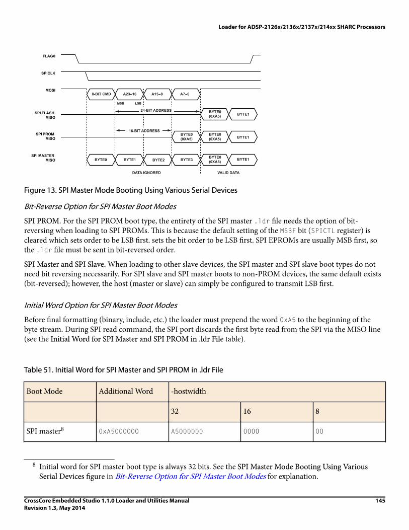
SPICLK
MOSI
SPI FLASH MISO
SPI PROM MISO
SPI MASTER MISO
FLAG0
51ADMC TIB-8 -8A23- 7A61 -0
BYTE0(0XA5) BYTE1
MSB LSB
BYTE0(0XA5) BYTE1
BYTE0(0XA5)
BYTE0(0XA5) BYTE1BYTE3BYTE1 BYTE2BYTE0
VALID DATADATA IGNORED
24-BIT ADDRESS
16-BIT ADDRESS
Figure 13. SPI Master Mode Booting Using Various Serial Devices
Bit-Reverse Option for SPI Master Boot Modes
SPI PROM. For the SPI PROM boot type, the entirety of the SPI master .ldr file needs the option of bit-reversing when loading to SPI PROMs. This is because the default setting of the MSBF bit (SPICTL register) iscleared which sets order to be LSB first. sets the bit order to be LSB first. SPI EPROMs are usually MSB first, sothe .ldr file must be sent in bit-reversed order.
SPI Master and SPI Slave. When loading to other slave devices, the SPI master and SPI slave boot types do notneed bit reversing necessarily. For SPI slave and SPI master boots to non-PROM devices, the same default exists(bit-reversed); however, the host (master or slave) can simply be configured to transmit LSB first.
Initial Word Option for SPI Master Boot Modes
Before final formatting (binary, include, etc.) the loader must prepend the word 0xA5 to the beginning of thebyte stream. During SPI read command, the SPI port discards the first byte read from the SPI via the MISO line(see the Initial Word for SPI Master and SPI PROM in .ldr File table).
Table 51. Initial Word for SPI Master and SPI PROM in .ldr File
Boot Mode Additional Word -hostwidth
32 16 8
SPI master8 0xA5000000 A5000000 0000 00
8 Initial word for SPI master boot type is always 32 bits. See the SPI Master Mode Booting Using VariousSerial Devices figure in Bit-Reverse Option for SPI Master Boot Modes for explanation.
Loader for ADSP-2126x/2136x/2137x/214xx SHARC Processors
CrossCore Embedded Studio 1.1.0 Loader and Utilities ManualRevision 1.3, May 2014
145

Boot Mode Additional Word -hostwidth
32 16 8
A500 00
00
A5
SPI PROM9 0xA5 A5 A5 A5
SPI PROM. For the SPI PROM boot type, the word 0xA5 prepended to the stream is one byte in length. SPIPROMs receives a 24-bit read command before any data is sent to the processor, the processor then discards thefirst byte it receives after this 24-bit opcode is sent (totaling one 32-bit word).
SPI Master. For the SPI master boot type, the word 0xA5000000 prepended to the stream is 32 bits in length. AnSPI host configured as a slave begins sending data to the processor while the processor is sending the 24-bitPROM read opcode. These 24-bits must be zero-filled because the processor discards the first 32-bit word that itreceives from the slave.
iNote:
Initial word option is only required for SPI master/prom boot mode. The CrossCore Embedded Studiotools automatically handle this in the loader file generation process for SPI boot devices.
With bit reversing for SPI master boot mode, the 32-bit word is handled according to the host width. With bitreversing for SPI PROM boot, the 8-bit word is reversed as a byte and prepended (see the Default Settings forPROM and SPI Boot Modes table).
Table 52. Default Settings for PROM and SPI Boot Modes
Boot Type Selection Host Width Output Format Bit Reverse Initial Word
-bprom 8 Intel hex No -
-bspislave 32 ASCII No -
-bspiflash 32 ASCII No -
-bspimaster 32 ASCII No 0x000000a5
9 Initial word for SPI PROM boot type is always 8 bits. See the SPI Master Mode Booting Using VariousSerial Devices figure in Bit-Reverse Option for SPI Master Boot Modes for explanation
Loader for ADSP-2126x/2136x/2137x/214xx SHARC Processors
146 CrossCore Embedded Studio 1.1.0 Loader and Utilities ManualRevision 1.3, May 2014

Boot Type Selection Host Width Output Format Bit Reverse Initial Word
-bspiprom 8 Intel hex Yes 0xa5
Booting From an SPI Flash (24-Bit Address)
For SPI flash devices, the format of the boot stream is identical to that used in SPI slave mode, with the first byteof the boot stream being the first byte of the kernel. This is because SPI flash devices do not drive out data untilthey receive an 8-bit command and a 24-bit address.
Booting From an SPI PROM (16-Bit Address)
The the SPI Master Mode Booting Using Various Serial Devices figure in Bit-Reverse Option for SPI Master BootModes shows the initial 32-bit word sent out from the processor from the perspective of the serial PROM device.
As shown in the figure, SPI EEPROMs only require an 8-bit opcode and a 16-bit address. These devices begintransmitting on clock cycle 24. However, because the processor is not expecting data until clock cycle 32, it isnecessary for the loader to pad an extra byte to the beginning of the boot stream when programming the PROM.In other words, the first byte of the boot kernel is the second byte of the boot stream.
Booting From an SPI Host Processor (No Address)
Typically, host processors in SPI slave mode transmit data on every SPICLK cycle. This means that the first fourbytes that are sent by the host processor are part of the first 32-bit word that is thrown away by the processor (seethe SPI Master Mode Booting Using Various Serial Devices figure in Bit-Reverse Option for SPI Master BootModes). Therefore, it is necessary for the loader to pad an extra four bytes to the beginning of the boot streamwhen programming the host; for example, the first byte of the kernel is the fifth byte of the boot stream.
Reserved (No Boot) ModeIn no boot mode, upon reset, the processor starts executing the application stored in the internal boot kernel.
ADSP-2126x/2136x/2137x/214xx Processor Boot KernelsThe boot-loading process starts with a transfer of the boot kernel program into the processor memory. The bootkernel sets up the processor and loads boot data. After the boot kernel finishes initializing the rest of the system,the boot kernel loads boot data over itself with a final DMA transfer.
The ADSP-2126x/2136x/2137x/214xx Default Boot Kernel Files table lists the ADSP-2126x/2136x/2137x/214xxboot kernels shipped with CrossCore Embedded Studio.
Loader for ADSP-2126x/2136x/2137x/214xx SHARC Processors
CrossCore Embedded Studio 1.1.0 Loader and Utilities ManualRevision 1.3, May 2014
147

Table 53. ADSP-2126x/2136x/2137x/214xx Default Boot Kernel Files
Processor PROM SPI Slave, SPI Flash, SPIMaster, SPI PROM
Link Port Boot(ADSP-2146x)
ADSP-2126x 26x_prom.dxe 26x_spi.dxe N/A
ADSP-21362,ADSP-21363,ADSP-21364,ADSP-21365,ADSP-21366
36x_prom.dxe 36x_spi.dxe N/A
ADSP-21367,ADSP-21368,ADSP-21369
369_prom.dxe 369_spi.dxe N/A
ADSP-21371 371_prom.dxe 371_spi.dxe N/A
ADSP-21375 375_prom.dxe 375_spi.dxe N/A
ADSP-21467,ADSP-21469
469_prom.dxe 469_spi.dxe 469_link.dxe
ADSP-21477,ADSP-21478,ADSP-21479
479_prom.dxe 479_spi.dxe N/A
ADSP-21483,ADSP-21486,ADSP-21487,ADSP-21488,ADSP-21489
489_prom.dxe 489_spi.dxe N/A
At processor reset, a boot kernel is loaded into the seg_ldr memory segment as defined in the LinkerDescription File for the default loader kernel that corresponds to the target processor, for example,2126x_ldr.ldf, which is stored in the <install_path>/SHARC/ldr/26x_prom directory of the targetprocessor.
Boot Kernel Modificatio and Loader IssuesBoot kernel customization is required for some systems. In addition, the operation of other tools (such as theC/C++ compiler) is influenced by whether the loader utility is used.
Loader for ADSP-2126x/2136x/2137x/214xx SHARC Processors
148 CrossCore Embedded Studio 1.1.0 Loader and Utilities ManualRevision 1.3, May 2014

If you do not specify a boot kernel file via the Loader > General page of theTool Settings dialog box in the IDE(or via the-l command-line switch), the loader utility places a default boot kernel (see the ADSP-2126x/2136x/2137x/214xx Default Boot Kernel Files table in ADSP-2126x/2136x/2137x/214xx Processors Boot Kernels) in theloader output file based on the specified boot type.
If you do not want to use any boot kernel file, check the No kernel (-nokernel) box (or specify the -nokernelcommand-line switch). The loader utility places no boot kernel in the loader output file.
• To omit a boot kernel. The -nokernel switch denotes that a running on the processor (already booted)subroutine imports the .ldr file. The loader utility does not insert a boot kernel into the .ldr file-a similarsubroutine is present already on the processor. Instead, the loader file begins with the first header of the firstblock of the boot stream.
• To omit any interrupt vector table (IVT) handling. In internal boot mode, the boot stream is not imported by aboot kernel executing from within the IVT; no self-modifying FINAL_INIT code (which overwrites itself withthe IVT) is needed. Thus, the loader utility does not give any special handling to the 256 instructions located inthe IVT (0x80000-0x800FF for ADSP-2126x processors and 0x90000-0x900FF for ADSP-2136x processors).Instead, the IVT code or data are handled like any other range of memory.
• To omit an initial word of 0xa5. When -nokernel is selected, the loader utility does not place an initial word(A5) in the boot stream as required for SPI master booting.
• To replace the FINAL_INIT block with a USER_MESG header. The FINAL_INIT block (which typically containsthe IVT code) should not be included in the .ldr file because the contents of the IVT (if any) is incorporatedin the boot stream. Instead, the loader utility appends one final bock header to terminate the loader file.
The final block header has a block tag of 0x0 (USER_MESG). The header indicates to a subroutine processing theboot stream that this is the end of the stream. The header contains two 32-bit data words, instead of count andaddress information (unlike the other headers). The words can be used to provide version number, errorchecking, additional commands, return addresses, or a number of other messages to the importing subroutineon the processor.
The two 32-bit values can be set on the command line as arguments to the -nokernel[message1, message2]switch (see the ADSP-2126x/2136x/2137x/214xx Loader Switches table in Loader Command-Line Switches forADSP-2126x/2136x/2137x/214xx Processors. The first optional argument is msg_word1, and the secondoptional argument is msg_word2, where the values are interpreted as 32-bit unsigned numbers. If only oneargument is issued, that argument is msg_word1. It is not possible to specify msg_word2 without specifyingmsg_word1.) If one or no arguments are issued at the command line, the default values for the arguments are0x00000000.
The Internal Booting: USER_MESG Block Header Format listing shows a sample format for the USER_MESGheader.
Internal Booting: USER_MESG Block Header Format
0x00000000 /* USER_MESG tag */
0x00000000 /* msg_word1 (1st cmd-line parameter) */
0x00000000 /* msg_word2 (2nd cmd-line parameter) */
Loader for ADSP-2126x/2136x/2137x/214xx SHARC Processors
CrossCore Embedded Studio 1.1.0 Loader and Utilities ManualRevision 1.3, May 2014
149

Rebuilding a Boot Kernel File
If you modify the boot kernel source (.asm) file by inserting appropriate settings for your system, you mustrebuild the boot kernel (.dxe) before generating the boot-loadable (.ldr) file. Note the boot kernel source filealready contains default register configurations for the external memories (AMI/SDRAM/DDR2).
To Modify a Boot Kernel Source File
1. Copy the applicable boot kernel source file (26x_prom.asm, 26x_spi.asm, 36x_prom.asm, 36x_spi.asm,369_prom.asm, 369_spi.asm).
2. Apply the appropriate changes.
iNote:
Any modification requires that the RTI instruction should still be located at the required peripheral ISR,otherwise the booting may fail.
After modifying the boot kernel source file, rebuild the boot kernel (.dxe) file. Do this from within the IDE(refer to online help for details) or rebuild a boot kernel file from the command line.
Rebuilding a Boot Kernel Using Command Lines
Rebuild a boot kernel using command lines as follows.
PROM Booting. The default boot kernel source file for PROM booting is 26x_prom.asm for the ADSP-2126xprocessors. After copying the default file to my_prom.asm and modifying it to suit your system, use the followingcommand lines to rebuild the boot kernel.
easm21k -proc ADSP-21262 my_prom.asm
linker -T 2162x_ldr.ldf my_prom.doj
SPI Booting. The default boot kernel source file for link booting is 2126x_SPI.asm for the ADSP-2126xprocessors. After copying the default file to my_SPI.asm and modifying it to suit your system, use the followingcommand lines to rebuild the boot kernel:
easm21k -proc ADSP-21262 my_SPI.asm
linker -T 2126x_ldr.ldf my_SPI.doj
Loader File Issues
If you modify the boot kernel for the PROM or SPI booting modes, ensure that the seg_ldr memory segment isdefined in the .ldf file. Refer to the source of this memory segment in the .ldf file located in the ldrinstallation directory of the target processor.
Because the loader utility uses the RESET vector location during the boot-load process, avoid placing code at theaddress. When using any of the processor's power-up booting modes, ensure that the address does not contain acritical instruction, because the address is not executed during the booting sequence. Place a NOP or IDLE in thislocation. The loader utility generates a warning if the RESET vector location does not contain NOP or IDLE.
Loader for ADSP-2126x/2136x/2137x/214xx SHARC Processors
150 CrossCore Embedded Studio 1.1.0 Loader and Utilities ManualRevision 1.3, May 2014

iNote:
When creating the loader file, specify the name of the customized boot kernel executable in the Kernel file(-l) field on the CrossCore SHARC Loader > General page of the Tool Settings dialog box.
ADSP-2126x/2136x/2137x/214xx Processor Boot StreamsThe loader utility generates and inserts a header at the beginning of a block of contiguous data and instructionsin the loader file. The kernel uses headers to properly place blocks into processor memory. The architecture ofthe header follows the convention used by other SHARC processors.
For all of the ADSP-2126x/2136x/2137x/214xx processor boot types, the structures of block header are the same.The header consists of three 32-bit words: the block tag, word count, and destination address. The order of thesewords is as follows.
0x000000TT First word. Tag of the data block (T)
0x0000CCCC Second word. Data word length or data word count (C) of the data block.
0xAAAAAAAA Third word. Start address (A) of the data block.
Boot Stream Block TagsThe ADSP-2126x/2136x/2137x/214xx Processor Block Tags table details the processor block tags.
Table 54. ADSP-2126x/2136x/2137x/214xx Processor Block Tags
Tag Count 1 Address Padding
0x0 FINAL_INIT None
0x1 ZERO_LDATA Number of 16-, 32-, or 64-bit words
Logical short, normal, orlong word address
None
0x2 ZERO_L48 2 Number of 48-bit words Logical normal word(ISA) or Short word(VISA) address
None
0x3 INIT_L16 Number of 16-bit words Logical short wordaddress
If count is odd, pad with16-bit zero word; see INIT_L16 Blocks fordetails.
Loader for ADSP-2126x/2136x/2137x/214xx SHARC Processors
CrossCore Embedded Studio 1.1.0 Loader and Utilities ManualRevision 1.3, May 2014
151

Tag Count 1 Address Padding
0x4 INIT_L32 Number of 32-bit words Logical normal wordaddress
None
0x5 INIT_L48 2 Number of 48-bit words Logical normal word(ISA) or Short word(VISA) address
If count is odd, pad with48-bit zero word; see INIT_L48 Blocks fordetails.
0x6 INIT_L64 Number of 64-bit words Logical long word address None; see INIT_L64Blocks for details.
0x7 ZERO_EXT8 Number of 32-bit words Physical external address None
0x8 ZERO_EXT16 Number of 32-bit words Physical external address None
0x9 INIT_EXT8 Number of 32-bit words Physical external address None
0xA INIT_EXT16 Number of 32-bit words Physical external address None
0xB MULTI_PROC forADSP-21368,ADSP-2146x processors
Processor IDs (bits 0-7);see Multi-Application(Multi-DXE)Management for details.
Offset to the nextprocessor ID in words (32bits)
None
0x0 USR_MESG msg_word1 msg_word2 None
1 The count is the actual number of words and does NOT included padded words added by the loader utility.
2 40-bit floating point data and 48-bit ISA/VISA instructions words are treated identically.
The ADSP-2126x/2136x/2137x/214xx processor uses eleven block tags, a lesser number of tags compared toother SHARC predecessors.
ZERO_INIT BlocksThere is only one initialization tag per width because there is no need to draw distinction between pm and dmsections during initialization. The same tag is used for 16-bit (short word), 32-bit (normal word), and 64-bit(long word) blocks that contain only zeros. The 0x1 tag is used for ZERO_LDATA blocks of 16-bit, 32-bit, and 64-bit words. The 0x2 tag is used for ZERO_L48 blocks of 40-bit floating point data and 48-bit ISA (VISAinstructions ADSP-214xx).
For clarity, the letter L has been added to the names of the internal block tags. L indicates that the associatedsection header uses the logical word count and logical address. Previous SHARC boot kernels do not use logical
Loader for ADSP-2126x/2136x/2137x/214xx SHARC Processors
152 CrossCore Embedded Studio 1.1.0 Loader and Utilities ManualRevision 1.3, May 2014
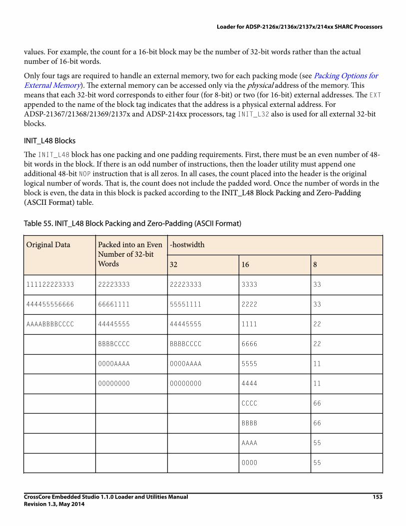
values. For example, the count for a 16-bit block may be the number of 32-bit words rather than the actualnumber of 16-bit words.
Only four tags are required to handle an external memory, two for each packing mode (see Packing Options forExternal Memory). The external memory can be accessed only via the physical address of the memory. Thismeans that each 32-bit word corresponds to either four (for 8-bit) or two (for 16-bit) external addresses. The EXTappended to the name of the block tag indicates that the address is a physical external address. ForADSP-21367/21368/21369/2137x and ADSP-214xx processors, tag INIT_L32 also is used for all external 32-bitblocks.
INIT_L48 Blocks
The INIT_L48 block has one packing and one padding requirements. First, there must be an even number of 48-bit words in the block. If there is an odd number of instructions, then the loader utility must append oneadditional 48-bit NOP instruction that is all zeros. In all cases, the count placed into the header is the originallogical number of words. That is, the count does not include the padded word. Once the number of words in theblock is even, the data in this block is packed according to the INIT_L48 Block Packing and Zero-Padding(ASCII Format) table.
Table 55. INIT_L48 Block Packing and Zero-Padding (ASCII Format)
Original Data Packed into an EvenNumber of 32-bitWords
-hostwidth
32 16 8
111122223333 22223333 22223333 3333 33
444455556666 66661111 55551111 2222 33
AAAABBBBCCCC 44445555 44445555 1111 22
BBBBCCCC BBBBCCCC 6666 22
0000AAAA 0000AAAA 5555 11
00000000 00000000 4444 11
CCCC 66
BBBB 66
AAAA 55
0000 55
Loader for ADSP-2126x/2136x/2137x/214xx SHARC Processors
CrossCore Embedded Studio 1.1.0 Loader and Utilities ManualRevision 1.3, May 2014
153

Original Data Packed into an EvenNumber of 32-bitWords
-hostwidth
32 16 8
0000 44
0000 44
CC
CC
BB
INIT_L16 Blocks
For 16-bit initialization blocks, the number of 16-bit words in the block must be even. If an odd number of 16-bit words is in the block, then the loader utility adds one additional word (all zeros) to the end of the block, asshown in the INIT_L16 Block Packing and Zero-Padding (ASCII Format) table. The count stored in the headeris the actual number of 16-bit words. The count does not include the padded word.
Table 56. INIT_L16 Block Packing and Zero-Padding (ASCII Format)
Original Data Packed into an EvenNumber of 32-bitWords
-hostwidth
32 16 8
1122 33441122 33441122 1122 22
3344 00005566 00005566 3344 11
5566 5566 44
0000 33
66
55
00
00
Loader for ADSP-2126x/2136x/2137x/214xx SHARC Processors
154 CrossCore Embedded Studio 1.1.0 Loader and Utilities ManualRevision 1.3, May 2014

INIT_L64 Blocks
For 64-bit initialization blocks, the data is packed as shown in the INIT_L64 Block Packing (ASCII Format)table.
Table 57. INIT_L64 Block Packing (ASCII Format)
Original Data Packed into an EvenNumber of 32-bitWords
-hostwidth
32 16 8
1111222233334444 33334444 33334444 4444 44
11112222 11112222 3333 44
2222 33
1111 33
22
22
11
11
MULT_PROC Blocks
The 0xB tag is for multiprocessor systems, exclusively supported on ADSP-21368 and ADSP-2146x processors.The tag indicates that the header is a processor ID header with the ID values and offset values stored in theheader. A block can have multiple IDs in its block header, which makes it possible to boot the block into multipleprocessors.
Two data tags, USER_MESG and FINAL_INIT, differ from the standard format for other SHARC data tags. TheUSER_MESG header is described in Boot Kernel Modification and Loader Issues, and the FINAL_INIT header in FINAL_INIT Blocks.
FINAL_INIT Blocks
The final 256-instructions of the .ldr file contain the instructions for the IVT. The instructions are initialized bya special self-modifying subroutine in the boot kernel (see Listing 7-2). To support the self-modifying code, theloader utility modifies the FINAL_INIT block as follows:
Loader for ADSP-2126x/2136x/2137x/214xx SHARC Processors
CrossCore Embedded Studio 1.1.0 Loader and Utilities ManualRevision 1.3, May 2014
155

1. Places a multi-function instruction at the fifth instruction of the block: The loader utility places theinstruction R0=R0-R0, DM(I4,M5)=R9, PM(I12,M13)=R11; at RESET vector location. The instructionoverwrites whatever instruction is at that address. The opcode for this instruction is 0x39732D802000.
2. Places an RTI instruction in the IVT: The loader utility inserts an RTI instruction (opcode 0x0B3E00000000)at the first address in the IVT entry associated with the boot-source. Unlike the multifunction instructionplaced at RESET vector location which overwrites the data, the loader utility preserves the user-specifiedinstruction which the RTI replaces. This instruction is stored in the header for FINAL_INIT as shown inListing 7-2.
• For parallel boot mode, the RTI is placed at address 0x80050 for ADSP-2126x processors, at 0x90050 forADSP-2136x/2137x processors, and at 0x8C050 for ADSP-214xx processors.
• For all SPI boot modes, the RTI is placed at address 0x80030 for ADSP-2126x processors, at 0x90030 forADSP-2136x/2137x processors, and at 0x8C030 for ADSP-214xx processors (high priority SPI interrupt).
3. Saves an IVT instruction in the FINAL_INIT block header. The count and address of a FINAL_INIT block areconstant; to avoid any redundancy, the count and address are not placed into the block header. Instead, the32-bit count and address words are used to hold the instruction that overwrites the RTI inserted into the IVT.Listing 7-2 illustrates the block header for FINAL_INIT if, for example, the opcode 0xAABBCCDDEEFF isassumed to be the user-intended instruction for the IVT.
FINAL_INIT Block Header Format
0x00000000 /* FINAL_INIT tag = 0x0 */
0xEEFF0000 /* LSBs of instructions */
0xAABBCCDD /* 4 MSBs of instructions */
FINAL_INIT Section (ADSP-2126x)
/* ====================== FINAL_INIT ======================== */
/* The FINAL_INIT subroutine in the boot kernel program sets up
a DMA to overwrite itself. The code is the very last piece that
runs in the kernel; it is self-modifying code, It uses a DMA
to overwrite itself, initializing the 256 instructions that
reside in the Interrupt Vector Table. */
/* ---------------------------------------------------------- */
final_init:
/* ----------- Setup for IVT instruction patch ------------- */
I8=0x80030; /* Point to SPI vector to patch from PX */
R9=0xb16b0000; /* Load opcode for "PM(0,I8)=PX" into R9 */
PX=pm(0x80002); /* User instruction destined for 0x80030
Loader for ADSP-2126x/2136x/2137x/214xx SHARC Processors
156 CrossCore Embedded Studio 1.1.0 Loader and Utilities ManualRevision 1.3, May 2014

is passed in the section-header for
FINAL_INIT. That instr. is initialized
upon completion of this DMA (see comments
below) using the PX register. */
R11=BSET R11 BY 9; /* Set IMDW to 1 for inst. write */
DM(SYSCTL)=R11; /* Set IMDW to 1 for inst. write */
/* ------ Setup loop for self-modifying instruction ------- */
I4=0x80004; /* Point to 0x080004 for self-modifying
code inserted by the loader at 0x80004
in bootstream */
R9=pass R9, R11=R12; /* Clear AZ, copy power-on value
of SYSCTL to R11 */
DO 0x80004 UNTIL EQ; /* Set bottom-of-loop address (loopstack)
to 0x80004 and top-of-loop (PC Stack)
to the address of the next
instruction. */
PCSTK=0x80004; /* Change top-of-loop value from the
address of this instruction to
0x80004. */
/* ------------- Setup final DMA parameters --------------- */
R1=0x80000;DM(IISX)=R1; /* Setup DMA to load over ldr */
R2=0x180; DM(CSX)=R2; /* Load internal count */
DM(IMSX)=M6; /* Set to increment internal ptr */
/*----------------- Enable SPI interrupt --------------------*/
bit clr IRPTL SPIHI; /* Clear any pending SPI interr. latch */
bit set IMASK SPIHI; /* Enable SPI receive interrupt */
bit set MODE1 IRPTEN; /* Enable global interrupts */
FLUSH CACHE; /* Remove any kernel instr's from cache */
Loader for ADSP-2126x/2136x/2137x/214xx SHARC Processors
CrossCore Embedded Studio 1.1.0 Loader and Utilities ManualRevision 1.3, May 2014
157
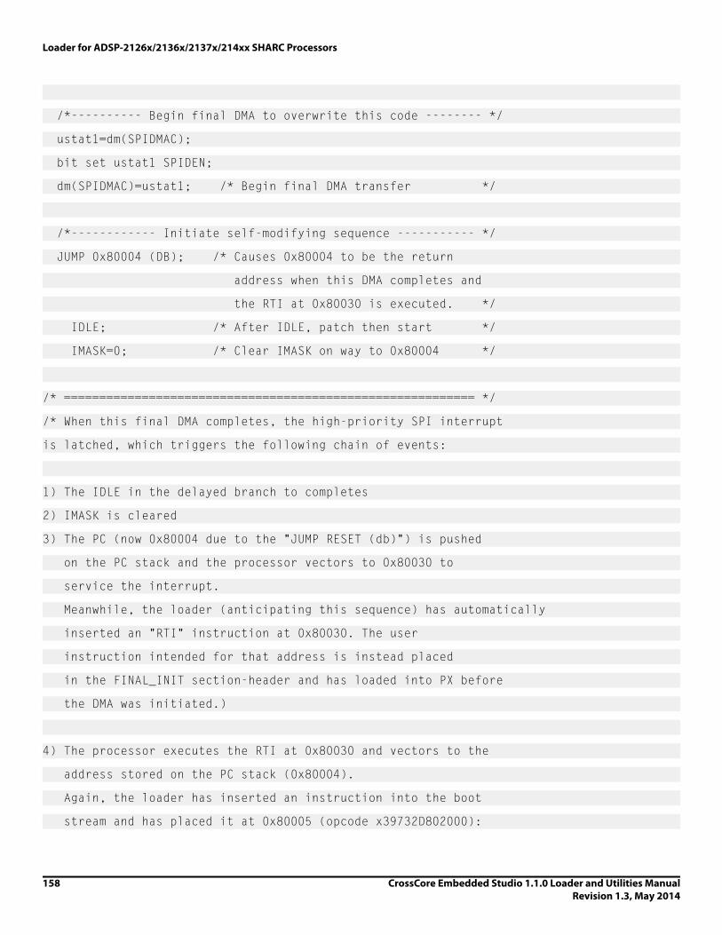
/*---------- Begin final DMA to overwrite this code -------- */
ustat1=dm(SPIDMAC);
bit set ustat1 SPIDEN;
dm(SPIDMAC)=ustat1; /* Begin final DMA transfer */
/*------------ Initiate self-modifying sequence ----------- */
JUMP 0x80004 (DB); /* Causes 0x80004 to be the return
address when this DMA completes and
the RTI at 0x80030 is executed. */
IDLE; /* After IDLE, patch then start */
IMASK=0; /* Clear IMASK on way to 0x80004 */
/* ========================================================== */
/* When this final DMA completes, the high-priority SPI interrupt
is latched, which triggers the following chain of events:
1) The IDLE in the delayed branch to completes
2) IMASK is cleared
3) The PC (now 0x80004 due to the "JUMP RESET (db)") is pushed
on the PC stack and the processor vectors to 0x80030 to
service the interrupt.
Meanwhile, the loader (anticipating this sequence) has automatically
inserted an "RTI" instruction at 0x80030. The user
instruction intended for that address is instead placed
in the FINAL_INIT section-header and has loaded into PX before
the DMA was initiated.)
4) The processor executes the RTI at 0x80030 and vectors to the
address stored on the PC stack (0x80004).
Again, the loader has inserted an instruction into the boot
stream and has placed it at 0x80005 (opcode x39732D802000):
Loader for ADSP-2126x/2136x/2137x/214xx SHARC Processors
158 CrossCore Embedded Studio 1.1.0 Loader and Utilities ManualRevision 1.3, May 2014

R0=R0-R0,DM(I4,M5)=R9,PM(I12,M13)=R11;
This instruction does the following.
A) Restores the power-up value of SYSCTL (held in R11).
B) Overwrites itself with the instruction "PM(0,I8)=PX;"
The first instruction of FINAL_INIT places the opcode for
this new instruction, 0xB16B00000000, into R9.
C) R0=R0-R0 causes the AZ flag to be set.
This satisfies the termination-condition of the loop set up
in FINAL_INIT ("DO RESET UNTIL EQ;"). When a loop condition
is achieved within the last three instructions of a loop,
the processor branches to the top-of-loop address (PCSTK)
one final time.
5) We manually changed this top-of-loop address 0x80004, and so to conclude the kernel, the processor executes the instruction
at 0x80004 *again*.
6) There's a new instruction at 0x80004: "PM(0,I8)=PX;". This
initializes the user-intended instruction at 0x80030 (the vector
for the High-Priority-SPI interrupt).
At this point, the kernel is finished, and execution continues
at 0x80005, with the only trace as if nothing happened! */
/* ========================================================== */
Multi-Application (Multi-DXE) ManagementUp to four ADSP-21367/21368/21369/21371/21375, and two ADSP-214xx processors can be clustered togetherand supported by the CrossCore Embedded Studio loader utility. In PROM boot mode, all of the processors canboot from the same PROM. The loader utility assigns an input executable (.dxe) file to a processor ID or to anumber of processor IDs, provided a corresponding loader option is selected on the properties page or on thecommand line.
Loader for ADSP-2126x/2136x/2137x/214xx SHARC Processors
CrossCore Embedded Studio 1.1.0 Loader and Utilities ManualRevision 1.3, May 2014
159

The loader utility inserts the ID into the output boot stream using the multiprocessor tag MULTI_PROC (see theADSP-2126x/2136x/2137x/214xx Processor Block Tags table in Boot Stream Block Tags). The loader utility alsoinserts the offset (the 32-bit word count of the boot stream built from the input executable (.dxe) file) into theboot stream. The MULTI_PROC tag enables the boot kernel to identify each section of the boot stream with theexecutable (.dxe) file from which that section was built. The Multiprocessor Boot Stream figure shows themultiprocessor boot stream structure.
BOOT KERNEL
......
1st .dxe BLOCK HEADER
1st .dxe DATA BLOCKS
2nd .dxe BLOCK HEADER
2nd .dxe DATA BLOCKS
......
Figure 14. Multiprocessor Boot Stream
The processor ID of the corresponding processor is indicated in a 32-bit word, which has the Nth bit set forthe .dxe file corresponding to ID=N. The Multiprocessor ID Fields table shows possible ID fields.
Table 58. Multiprocessor ID Fields
Processor ID Number Loader ID Field
0 0x00000001
1 0x00000002
2 0x00000004
3 0x00000008
4 0x00000010
5 0x00000020
6 0x00000040
Loader for ADSP-2126x/2136x/2137x/214xx SHARC Processors
160 CrossCore Embedded Studio 1.1.0 Loader and Utilities ManualRevision 1.3, May 2014

Processor ID Number Loader ID Field
7 0x00000080
1 && 4 0x00000012
6 && 7 0x000000C0
The multiprocessor tag, processor ID, and the offset are encapsulated in a multiprocessor header. Themultiprocessor header includes three 32-bit words: the multiprocessor tag; the ID (0-7) of the associatedprocessor .dxe file in the lowest byte of a word; and the offset to the next multiprocessor tag. The loader -id#exe=filename switch is used to assign a processor ID number to an executable file. The loader -id#ref=Nswitch is used to share the same executable file by setting multiple bits in the ID field. The MultiprocessorHeader figure shows the multiprocessor header structure.
0xB
PROCESSOR ID
OFFSET TO THE NEXT MULTIPROCESSOR HEADER
Figure 15. Multiprocessor Header
ADSP-2126x/2136x/2137x Processor Compression Support
iNote:
Compression is not supported on the ADSP-214xx processors.
The loader utility for the ADSP-2126x/2136x/2137x processors offers a loader file (boot stream) compressionmechanism known as zLib. The zLib compression is supported by a third party dynamic link library, zLib1.dll.Additional information about the library can be obtained from the http://www.zlib.net Web site.
The zLib1 dynamic link library is included with CrossCore Embedded Studio. The library functions perform theboot stream compression and decompression procedures when the appropriate options are selected for theloader utility.
The boot kernel with built-in decompression mechanism must perform the decompression on the compressedboot stream in a booting process. The default boot kernel with decompression functions are included withCrossCore Embedded Studio.
The loader -compression switch directs the loader utility to perform the boot stream compression from thecommand line. The IDE also offers a dedicated loader properties page (Compression) to manage thecompression from the graphical user interface.
Loader for ADSP-2126x/2136x/2137x/214xx SHARC Processors
CrossCore Embedded Studio 1.1.0 Loader and Utilities ManualRevision 1.3, May 2014
161

The loader utility takes two steps to compress a boot stream. First, the utility generates the boot stream in theconventional way (builds data blocks), then applies the compression to the boot stream. The decompressioninitialization is the reversed process: the loader utility decompresses the compressed stream first, then loads codeand data into memory segments in the conventional way.
The loader utility compresses the boot stream on the .dxe-by-.dxe basis. For each input .dxe file, the utilitycompresses the code and data together, including all code and data from any associated shared memory (.sm)files. The loader utility, however, does not compress automatically any data from any associated overlay files. Tocompress data and code from the overlay file, call the utility with the -compressionOverlay switch, either fromthe properties page or from the command line.
Compressed StreamsThe basic structure of a loader file with compressed streams is shown in the Loader File With CompressedStreams figure.
KERNEL WITH DECOMPRESSION ENGINE
......
1st .dxe COMPRESSED STREAM
1st .dxe UNCOMPRESSED STREAM
2nd .dxe COMPRESSED STREAM
2nd .dxe UNCOMPRESSED STREAM
......
Figure 16. Loader File With Compressed Streams
The kernel code with the decompression engine is on the top of the loader file. This section is loaded into theprocessor first and is executed first when a boot process starts. Once the kernel code is executed, the rest of thestream is brought into the processor. The kernel code calls the decompression routine to perform thedecompression operation on the stream, and then loads the decompressed stream into the processor's memoryin the same manner a conventional kernel does when it encounters a compressed stream.
The Compressed Block figure shows the structure of a compressed boot stream.
COMPRESSED BLOCK HEADER
COMPRESSED STREAM
Figure 17. Compressed Block
Loader for ADSP-2126x/2136x/2137x/214xx SHARC Processors
162 CrossCore Embedded Studio 1.1.0 Loader and Utilities ManualRevision 1.3, May 2014

Compressed Block HeadersA compressed stream always has a header, followed by the payload compressed stream.
The compressed block header is comprised of three 32-bit words. The structure of a compressed block header isshown in the Compressed Block Header figure.
COMPRESSED BLOCK HEADER
COMPRESSED STREAM
Figure 18. Compressed Block Header
The first 32-bit word of the compressed block header holds the compression flag, 0x00002000, which indicatesthat it is a compressed block header.
The second 32-bit word of the compressed block header hold the size of the compression window (takes theupper 16 bits) and padded word count (takes the lower 16 bits). For the ADSP-2126x/2136x/2137x processors,the loader utility always rounds the byte count of the compressed stream to be a multiple of 4. The loader utilityalso pads 3 bytes to the compressed stream if the byte count of the compressed stream from the loadercompression engine is not a multiple of 4. An actual padded byte count is a value between 0x0000 and 0x0003.
The compression window size is 8-15 bits, with the default value of 9 bits. The compression window size specifiesto the compression engine a number of bytes taken from the window during the compression. The window sizeis the 2's exponential value.
The next 32 bits of the compressed block header holds the value of the compressed stream byte count, excludingthe byte padded.
A window size selection affects, more or less, the outcome of the data compression. Streams in decompressionwindows of different sizes are, in general, different and most likely not compatible to each other. If you arebuilding a custom decompression kernel, ensure the same compression window size is used for both the loaderutility and the kernel. In general, a bigger compression window size leads to a smaller outcome stream. However,the benefit of a big window size is marginal in some cases. An outcome of the data compression depends on anumber of factors, and a compression window size selection is only one of them. The other important factor isthe coding structure of an input stream. A compression window size selection can not cause a much smalleroutcome stream if the compression ability of the input stream is low.
Uncompressed StreamsFollowing the compressed streams, the loader utility file includes the uncompressed streams. The uncompressedstreams include application codes, conflicted with the code in the initialization blocks in the processor's memoryspaces, and a final block. The uncompressed stream includes only a final block if there is no conflicted code. The
Loader for ADSP-2126x/2136x/2137x/214xx SHARC Processors
CrossCore Embedded Studio 1.1.0 Loader and Utilities ManualRevision 1.3, May 2014
163

final block can have a zero byte count. The final block indicates the end of the application to the initializationcode.
Overlay CompressionThe loader utility compresses the code and data from the executable .dxe and shared memory .sm files when the -compression command-line switch is used alone, and leaves the code and data from the overlay (.ovl) filesuncompressed. The -compressionOverlay switch directs the loader utility to compress the code and data fromthe .ovl files, in addition to compressing the code and data from the .dxe and .sm files.
The -compressionOverlay switch must be used in conjunction with -compression.
Booting Compressed StreamsThe ADSP-2126x/2136x/2137x Compressed Loader Stream: Booting Sequence figure shows the bootingsequence of a loader file with compressed streams. The loader file is prestored in the flash memory.
1. A a booting process is initialized by the processor.2. The processor brings the 256 words of the boot kernel from the flash memory to the processor's memory for
execution.3. The decompression engine is brought in.4. The compressed stream is brought in, then decompressed and loaded into the memory.5. The uncompressed stream is brought and loaded into memory, possibly to overwrite the memory spaces
taken by the compressed code.6. The final block is brought and loaded into the memory to overwrite the memory spaces taken by the boot
kernel.
BOOT KERNEL
DECOMPRESSION ENGINE
COMPRESSED STREAM
UNCOMPRESSED STREAM
FINAL BLOCK
FLASH MEMORY
MEMORY
PROCESSOR12
3
5
4
6
Figure 19. ADSP-2126x/2136x/2137x Compressed Loader Stream: Booting Sequence
Loader for ADSP-2126x/2136x/2137x/214xx SHARC Processors
164 CrossCore Embedded Studio 1.1.0 Loader and Utilities ManualRevision 1.3, May 2014

Decompression Kernel FileAs stated before, a decompression kernel .dxe file must be used when building a loader file with compressedstreams. The decompression kernel file has a built-in decompression engine to decompress the compressedstreams from the loader file.
A decompression kernel file can be specified from the loader properties page or from the command line via the -l userkernel switch. CrossCore Embedded Studio includes the default decompression kernel files, which theloader utility uses if no other kernel file is specified. If building a custom decompression kernel, ensure that youuse the same decompression function, and use the same compression window size for both the kernel and theloader utility.
The default decompression kernel files are stored in the <install_path>/SHARC/ldr/zlib directory ofCrossCore Embedded Studio. The loader utility uses the window size of 9 bits to perform the compressionoperation. The compression window size can be changed through the loader properties page or the -compressWS # command-line switch. The valid range for the window size is from 8 to 15 bits.
ADSP-2126x/2136x/2137x/214xx Processor Loader GuideLoader utility operations depend on the loader properties, which control how the utility processes executablefiles. You select features, such as boot modes, boot kernels, and output file formats via the properties. Theproperties are specified on the loader utility's command line or the Tool Settings dialog box in the IDE(CrossCore Blackfin Loader pages). The default loader settings for a selected processor are preset in the IDE.
iNote:
The IDE’s Tool Settings correspond to switches displayed on the command line.
These sections describe how to produce a bootable loader file (.ldr):
• Loader Command Line for ADSP-2126x/2136x/2137x/214xx Processors• CCES Loader Interface for ADSP-2126x/2136x/2137x/214xx Processors
Loader Command Line for ADSP-2126x/2136x/2137x/214xx ProcessorsThe loader utility uses the following command-line syntax for the ADSP-2126x, ADSP-2136x, ADSP-2137x, andADSP-214xx SHARC processors.
elfloader inputfile -proc processor -switch [switch]
where:
• inputfile - Name of the executable file (.dxe) to be processed into a single boot-loadable file. An input filename can include the drive and directory. Enclose long file names within straight quotes, "long file name".
• -proc processor - Part number of the processor (for example, -proc ADSP-21262) for which the loadablefile is built. The -proc switch is mandatory.
• -switch - One or more optional switches to process. Switches select operations and boot modes for the loaderutility. A list of all switches and their descriptions appear in Loader Command-Line Switches ADSP- 2126x/2136x/2137x/214xx Processors.
Loader for ADSP-2126x/2136x/2137x/214xx SHARC Processors
CrossCore Embedded Studio 1.1.0 Loader and Utilities ManualRevision 1.3, May 2014
165

iNote:
Command-line switches are not case-sensitive and may be placed on the command line in any order.
The following command line,
elfloader Input.dxe -bSPIflash -proc ADSP-21262
runs the loader utility with:
• Input.dxe - Identifies the executable file to process into a boot-loadable file. Note that the absence of the -oswitch causes the output file name to default to Input.ldr.
• -bspiflash - Specifies SPI flash port booting as the boot type for the boot-loadable file.• -proc ADSP-21262 - Specifies ADSP-21262 as the target processor.
Loader Command-Line Switches for ADSP-2126x/2136x/2137x/214xx ProcessorsThe ADSP-2126x/2136x/2137x/214xx Loader Switches table is a summary of the loader switches for theADSP-2126x, ADSP-2136x, ADSP-2137x, and ADSP-214xx processors.
Table 59. ADSP-2126x/2136x/2137x/214xx Loader Switches
Switch Description
-bprom
-bspislave|-bspi
-bspimaster
-bspiprom
-bspiflash
-blink
Specifies the boot mode. The -b switch directs the loader utility toprepare a boot-loadable file for the specified boot mode. The validmodes (boot types) are PROM, SPI slave, SPI master, SPI PROM,SPI flash, and link port (ADSP-2146x processors).
If -b does not appear on the command line, the default is -bprom.To use a custom boot kernel, the boot type selected with the -bswitch must correspond with the boot kernel selected with the -lswitch. Otherwise, the loader utility automatically selects a defaultboot kernel based on the selected boot type (see ADSP-2126x/2136x/2137x/214xx Processors Boot Kernels).
iNote:
Do not use with the -nokernel switch.
-compression Directs the loader utility to compress the application data andcode, including all data and code from the application-associatedshared memory files (see ADSP-2126x/2136x/2137x ProcessorsCompression Support). The data and code from the overlay filesare not compressed if this switch is used alone (see -compressionOverlay).
Loader for ADSP-2126x/2136x/2137x/214xx SHARC Processors
166 CrossCore Embedded Studio 1.1.0 Loader and Utilities ManualRevision 1.3, May 2014

Switch Description
-compressionOverlay Directs the loader utility to compress the application data andcode from the associated overlay files (see Overlay Compression).
iNote:
This switch must be used with -compression.
-compressWS # The -compressWS # switch specifies a compression window sizein bytes. The number is a 2's exponential value to be used by thecompression engine. The valid values are [8-15], with the defaultof 9.
-fhex
-fASCII
-fbinary
-fbyte
-finclude
-fs1
-fs2
-fs3
Specifies the format of a boot-loadable file (Intel hex-32, ASCII,binary, byte, include). If the -f switch does not appear on thecommand line, the default boot file format is Intel hex-32 forPROM and SPI PROM, ASCII for SPI slave, SPI flash, and SPImaster.
Available formats depend on the boot type selection (-b switch):
• For PROM and SPI PROM boot types, select a hex, ASCII, s1,s2, s3, or include format.
• For other SPI boot types, select an ASCII or binary format.• The byte format is used with -splitter only. The byte format is
not available for bootable loader files.
-h
or
-help
Invokes the command-line help, outputs a list of command-lineswitches to standard output, and exits. By default, the -h switchalone provides help for the loader driver. To obtain a help screenfor the target processor, add the -proc switch to the commandline.
For example: type elfloader -proc ADSP-21262 -h to obtainhelp for the ADSP-21262 processor.
-hostwidth [8|16|32] Sets up the word width for the .ldr file. By default, the wordwidth for PROM and SPI PROM boot modes is 8; for SPI slave,SPI flash, and SPI master boot modes is 32. The valid word widthsare:
• 8 for Intel hex 32 and Motorola S-records formats.• 8, 16, or 32 for ASCII, binary, and include formats.• 8, 16, or 32 for byte format when building with -splittersection_name.
Loader for ADSP-2126x/2136x/2137x/214xx SHARC Processors
CrossCore Embedded Studio 1.1.0 Loader and Utilities ManualRevision 1.3, May 2014
167

Switch Description
-id# exe=filename Specifies the processor ID. Directs the loader utility to use theprocessor ID (#) for a corresponding executable file (thefilename parameter) when producing a boot-loadable file. Thisswitch is used to produce a boot-loadable file to boot multipleprocessors. Valid values for # are 0, 1, 2, 3, 4, 5, 6, 7.
Do not use this switch for single-processor systems. For single-processor systems, use filename as a parameter without a switch.
iNote:
This switch is applicable to theADSP-21367/21368/21369/21371/21375 and ADSP-214xxprocessors only.
-id#ref=N Directs the loader utility to share the boot stream for processor Nwith processor #. If the executable file of the # processor isidentical to the executable of the N processor, the switch can beused to set the start address of the processor with ID of # to be thesame as that of the processor with ID of N. This effectively reducesthe size of the loader file by providing a single copy of the file totwo or more processors in a multiprocessor system.
The ADSP-21367/21378/21369/21371/213755] and ADSP-214xxprocessors support 8 processors, and the valid processor ids are 0,1, 2, 3, 4, 5, 6, 7.
iNote:
This switch is applicable to theADSP-21367/21368/21369/21371/21375 and ADSP-214xxprocessors only.
-l userkernel Directs the loader utility to use the specified userkernel and toignore the default boot kernel for the boot-loading routine in theoutput boot-loadable file.
iNote:
The boot kernel file selected with this switch mustcorrespond to the boot type selected with the -b switch).
If the -l switch does not appear on the command line, the loaderutility searches for a default boot kernel file in the installationdirectory, (see ADSP-2126x/2136x/2137x/214xx Processors Boot
Loader for ADSP-2126x/2136x/2137x/214xx SHARC Processors
168 CrossCore Embedded Studio 1.1.0 Loader and Utilities ManualRevision 1.3, May 2014

Switch Description
Kernels). For kernels with the decompression engine, see Decompression Kernel File.
iNote:
The loader utility does not search for any kernel file if -nokernel is selected.
-nokernel [message1, message2] Supports internal boot mode. The -nokernel switch directs theloader utility:
• Not to include the boot kernel code into the loader (.ldr) file.• Not to perform any special handling for the 256 instructions
located in the IVT.• To put two 32-bit hex messages in the final block header
(optional).• Not to include the initial word in the loader file.
For more information, see Boot Kernel Modification and LoaderIssues.
-o filename Directs the loader utility to use the specified filename as thename for the loader's output file. If the -o filename is absent, thedefault name is the root name of the input file with an .ldrextension.
-noZeroBlock The -noZeroBlock switch directs the loader utility not to buildzero blocks.
-p address Specifies the PROM offset start address. This PROM addresscorresponds to 0x80000 (ADSP-2126x processors) or to externalbank MS1 for ADSP-2136x/2137x/214xx processors. The -p switchstarts the boot-loadable file at the specified offset address in theEPROM.
If the p switch does not appear on the command line, the loaderutility starts the EPROM file at offset address 0x0.
-proc processor Specifies the processor. This is a mandatory switch. Theprocessor argument is one of the following:
ADSP-21261 ADSP-21262 ADSP-21266
ADSP-21362 ADSP-21363 ADSP-21364
Loader for ADSP-2126x/2136x/2137x/214xx SHARC Processors
CrossCore Embedded Studio 1.1.0 Loader and Utilities ManualRevision 1.3, May 2014
169

Switch Description
ADSP-21365 ADSP-21366 ADSP-21367
ADSP-21368 ADSP-21369 ADSP-21371
ADSP-21375 ADSP-21467 ADSP-21469
ADSP-21477 ADSP-21478 ADSP-21479
ADSP-21483 ADSP-21486 ADSP-21487
ADSP-21488 ADSP-21489
-retainSecondStageKernel Directs the loader utility to retain the decompression code in thememory at runtime.
iNote:
The -retainSecondStageKernel switch must be usedwith -compression.
-si-revision [none|any|x.x] Sets revision for the build, with x.x being the revision number forthe processor hardware. If -si-revision is not used, the target isa default revision from the supported revisions.
-splitter section_nameThe -splitter section_name switch provides for selectivelyextracting a section (section_name) from the DXE and writing itto a non-bootable .ldr file. The section name is a requiredargument for -splitter. It specifies what section the loader is toextract content from. All other sections are ignored.
iNote:
This switch is provided for the ADSP-214xx processorsonly. The -splitter section_name provides support forSW (VISA) sections or NW (normal-word).
-v
Outputs verbose loader messages and status information as theloader utility processes files.
-version Directs the loader utility to show its version information. Typeelfloader -version to display the version of the loader drive.
Add the -proc switch, for example, elfloader -procADSP-21262 -version to display version information of bothloader drive and SHARC loader.
Loader for ADSP-2126x/2136x/2137x/214xx SHARC Processors
170 CrossCore Embedded Studio 1.1.0 Loader and Utilities ManualRevision 1.3, May 2014
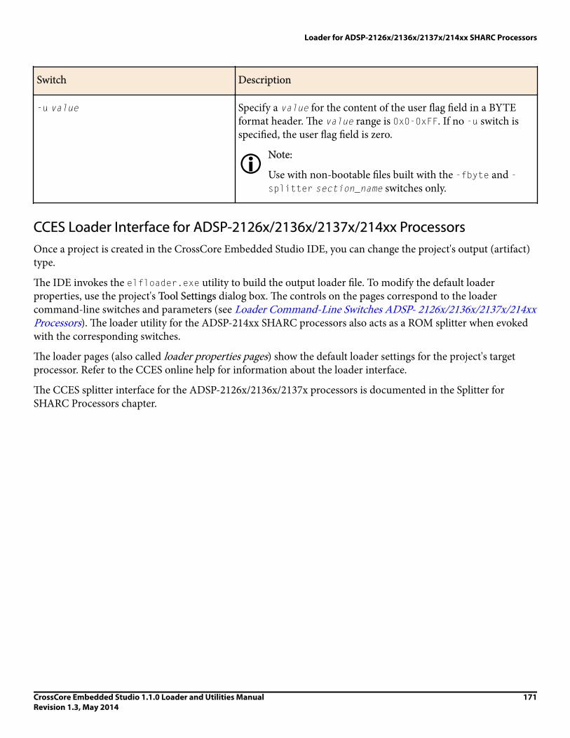
Switch Description
-u value Specify a value for the content of the user flag field in a BYTEformat header. The value range is 0x0-0xFF. If no -u switch isspecified, the user flag field is zero.
iNote:
Use with non-bootable files built with the -fbyte and -splitter section_name switches only.
CCES Loader Interface for ADSP-2126x/2136x/2137x/214xx ProcessorsOnce a project is created in the CrossCore Embedded Studio IDE, you can change the project's output (artifact)type.
The IDE invokes the elfloader.exe utility to build the output loader file. To modify the default loaderproperties, use the project's Tool Settings dialog box. The controls on the pages correspond to the loadercommand-line switches and parameters (see Loader Command-Line Switches ADSP- 2126x/2136x/2137x/214xxProcessors). The loader utility for the ADSP-214xx SHARC processors also acts as a ROM splitter when evokedwith the corresponding switches.
The loader pages (also called loader properties pages) show the default loader settings for the project's targetprocessor. Refer to the CCES online help for information about the loader interface.
The CCES splitter interface for the ADSP-2126x/2136x/2137x processors is documented in the Splitter forSHARC Processors chapter.
Loader for ADSP-2126x/2136x/2137x/214xx SHARC Processors
CrossCore Embedded Studio 1.1.0 Loader and Utilities ManualRevision 1.3, May 2014
171


10Splitter for SHARC Processors
This chapter explains how the splitter utility (elfspl21k.exe) is used to convert executable (.dxe) files intonon-bootable files for the ADSP-21xxx SHARC processors. Non-bootable PROM image files execute fromexternal memory of a processor. For SHARC processors, the utility creates a 64-/48-/40-/32-bit image file or animage file to match a physical memory size.
xAttention:
Users who are migrating from VisualDSP++
VisualDSP++ legacy splitter projects cannot be imported into the CrossCore Embedded Studio IDE.There is no SHARC splitter build artifact in the IDE. If attempting to import a VisualDSP++ legacy splitterproject, a status of "Not Converted" appears along with the following error messages:
The legacy SHARC splitter elfspl21k.exe is available with CrossCore Embedded Studio for command-line usage.
Splitter functionality for SHARC processors, beginning with the ADSP-214xx family, is available throughthe SHARC loader instead of the legacy splitter utility.
For SHARC processors, the splitter utility also properly packs the external memory data or code to match thespecified external memory widths if the logical width of the data or code is different from that of the physicalmemory.
In most instances, developers working with SHARC processors use the loader utility instead of the splitter. Oneof the exceptions is a SHARC system that can execute instructions from external memory. Refer to theIntroduction chapter for the splitter utility overview; the introductory material applies to both processorfamilies.
Splitter Command LineUse the following syntax for the SHARC splitter command line.
elfspl21k [-switch] -pm &|-dm &|-64 &| -proc part_number inputfile
Splitter for SHARC Processors
CrossCore Embedded Studio 1.1.0 Loader and Utilities ManualRevision 1.3, May 2014
173

or
elfspl21k [-switch] -s section_name inputfile
where:
• inputfile - Specifies the name of the executable file (.dxe) to be processed into a non-bootable file for a single-processor system. The name of the inputfile file must appear at the end of the command. The namecan include the drive, directory, file name, and file extension. Enclose long file names within straight quotes;for example, "long file name".
• -switch - One or more optional switches to process. Switches select operations for the splitter utility. Switchesmay be used in any order. A list of the splitter switches and their descriptions can be found in SplitterCommand-Line Switches.
• -pm &| -dm &| -64 - For SHARC processors, the &| symbol between the switches indicates AND/OR. Thesplitter command line must include one or more of -pm, -dm, or -64 (or the -s switch). The -64 switchcorresponds to DATA64 memory space.
• -s section_name - The -s switch can be used without the -pm, -dm, or -64 switch. The splitter command linemust include one or more of the -pm, -dm, and, -64 switches or the -s switch.
iNote:
Most items in the splitter command line are not case sensitive; for example, -pm and -PM areinterchangeable. However, the names of memory sections must be identical, including case, to the namesused in the executable.
Each of the following command lines,
elfspl21k -pm -o pm_stuff my_proj.dxe -proc ADSP-21161
elfspl21k -dm -o dm_stuff my_proj.dxe -proc ADSP-21161
elfspl21k -64 -o 64_stuff my_proj.dxe -proc ADSP-21161
elfspl21k -s seg-code -o seg-code my_proj.dxe
runs the splitter utility for the ADSP-21161 processor. The first command produces a PROM file for programmemory. The second command produces a PROM file for data memory. The third command produces a PROMfile for DATA64 memory. The fourth command produces a PROM file for section seg-code.
The switches on these command lines are as follows.
-pm
-dm
-64
Selects program memory (-pm), data memory (-dm), or DATA64 memory (-64) assources in the executable for extraction and placement into the image.
Because these are the only switches used to identify the memory source, thespecified sources are PM, DM, or DATA64 memory sections. Because no other contentswitches appear on these command lines, the output file format defaults to aMotorola 32-bit format, and the PROM word width of the output defaults to 8 bitsfor all PROMs.
Splitter for SHARC Processors
174 CrossCore Embedded Studio 1.1.0 Loader and Utilities ManualRevision 1.3, May 2014

-o pm_stuff
-o dm_stuff
-o seg-code
Specify names for the output files. Use different names so the output of a run doesnot overwrite the output of a previous run. The output names are pm_stuff.s_#and dm_stuff.s_#. The splitter utility adds the .s_# file extension to the outputfiles; # is a number that differentiates one output file from another.
my_proj.dxe Specifies the name of the input (.dxe) file to be processed into non-bootablePROM image files.
Splitter File SearchesFile searches are important in the splitter process. The splitter utility supports relative and absolute directorynames, default directories, and user-selected directories for file search paths. File searches occur as described inLoader File Searches in the Introduction chapter.
Splitter Output File ExtensionsThe splitter utility follows the conventions shown in the Splitter Output File Extensions table for output fileextensions.
Table 60. Splitter Output File Extensions
Extension File Description
.s_# Motorola S-record format file. The # indicates the position (0 = least significant, 1= next-to-least significant, and so on). For info about Motorola S-record fileformat, refer to Loader Output Files in Motorola S-Record Format in the FileFormats appendix.
.h_# Intel hex-32 format file. The # indicates the position (0 = least significant, 1 = next-to-least significant, and so on). For information about Intel hex-32 file for mat,refer to Splitter Output Files in Intel Hex-32 Format in the File Formats appendix.
.stk
Byte-stacked format file. These files are intended for host transfer of data, not forPROMs. For more information about byte stacked file format, format files, refer toSplitter Output Files in Byte-Stacked Format in the File Formats appendix.
Splitter Command-Line SwitchesA list of the splitter switches appears in the Splitter Command-Line Switches table.
Splitter for SHARC Processors
CrossCore Embedded Studio 1.1.0 Loader and Utilities ManualRevision 1.3, May 2014
175

Table 61. Splitter Command-Line Switches
Item Description
-64 The -64 (include DATA64 memory) switch directs the splitterutility to extract all sections declared as 64-bit memory sectionsfrom the input .dxe file. The switch influences the operation ofthe -ram and -norom switches, adding 64-bit data memory astheir target.
-dm The -dm (include data memory) switch directs the splitter utilityto extract memory sections declared as data memory ROM fromthe input .dxe file. The -dm switch influences the operation of the-ram and -norom switches, adding data memory as their target.
-f h
-f s1
-f s2
-f s3
-f b
The -f (PROM file format) switch directs the splitter utility togenerate a non-bootable PROM image file in the specified format.Available selection include:
• h-Intel hex-32 format• s1-Motorola EXORciser format• s2-Motorola EXORMAX format• s3-Motorola 32-bit format• b-byte stacked format
If the -f switch does not appear on the command line, the defaultformat for the PROM file is Motorola 32-bit (s3). For informationon file formats, see Build Files in the File Formats appendix.
-norom The -norom (no ROM in PROM) switch directs the splitter utilityto ignore ROM memory sections in the inputfile whenextracting information for the output image. The -dm and -pmswitches select data memory or program memory. The operationof the -s switch is not influenced by the -norom switch.
-o imagefile The -o (output file) switch directs the splitter utility to useimagefile as the name of the splitter output file(s). If notspecified, the default name for the splitter output file isinputfile.ext, where ext depends on the output format.
-pm The -pm (include program memory) switch directs the splitterutility to extract memory sections declared program memoryROM from the input.dxe file. The -pm switch influences the
Splitter for SHARC Processors
176 CrossCore Embedded Studio 1.1.0 Loader and Utilities ManualRevision 1.3, May 2014

Item Description
operation of the -ram and -norom switches, adding programmemory as the target.
-proc part_numberSpecifies the processor type to the splitter utility. Valid processorsare:
• ADSP-21160, ADSP-21161• ADSP-21261, ADSP-21262, ADSP-21266• ADSP-21363, ADSP-21364, ADSP-21365, ADSP-21366,ADSP-21367, ADSP-21368, ADSP-21369,
• ADSP-21371, ADSP-21375
-r#[# ]
The -r (PROM widths) switch specifies the number of PROMfiles and their width in bits. The splitter utility can create PROMfiles for 8-, 16-, and 32-bit wide PROMs. The default width is 8bits. Each # parameter specifies the width of one PROM file. Place# parameters in order from most significant to least significant.The sum of the # parameters must equal the bit width of thedestination memory (40 bits for DM, 48 bits for PM, or 64 bits for64-bit memory).
Example:
elfspl21k -dm -r 16 16 8 myfile.dxe
This command extracts data memory ROM from myfile.dxeand creates the following output PROM files.
• myfile.s_0-8 bits wide, contains bits 7-0• myfile.s_1-16 bits wide, contains bits 23-8• myfile.s_2-16 bits wide, contains bits 39-24
The width of the three output files is 40 bits.
-ram The -ram (include RAM in PROM) switch directs the splitterutility to extract RAM sections from the inputfile. The -dm, -pm, and -64 switches select the memory. The -s switch is notinfluenced by the -ram switch.
-s section_name The -s (include memory section) switch directs the splitter utilityto extract the content of one memory section (section_name)from the executable. The section_name argument is casesensitive and must exactly match the name as it appears in theLDF for the executable.
Splitter for SHARC Processors
CrossCore Embedded Studio 1.1.0 Loader and Utilities ManualRevision 1.3, May 2014
177

Item Description
You must also specify the switch -dm or -pm or -64 for thememory type. Rerun the splitter for any additional sections thatare required, changing the memory type switch and output file asneeded for each invocation.
iNote:
Short-word sections are not supported in the legacySHARC splitter. To split a SW section into a raw (non-bootable) format, use the new -splitter section_nameswitch in the SHARC ADSP-214xx loader.
-si-revision [none|any|x.x] Sets revision for the build, with x.x being the revision number forthe processor hardware. If -si-revision is not used, the target isa default revision from the supported revisions.
-u # (Byte-stacked format files only) The -u (user flags) switch, whichmay be used only in combination with the -f b switch, directsthe splitter utility to use the number # in the user-flags field of abyte stacked format file. If the -u switch is not used, the defaultvalue for the number is 0. By default, # is decimal. If # is prefixedwith 0x, the splitter utility interprets the number as hexadecimal.For more information, see Splitter Output Files in Byte-StackedFormat in the File Formats appendix.
-version Directs the splitter utility to show its version information.
Splitter for SHARC Processors
178 CrossCore Embedded Studio 1.1.0 Loader and Utilities ManualRevision 1.3, May 2014

11File Formats
CrossCore Embedded Studio supports many file formats, in some cases several for each development tool. Thisappendix describes file formats that are prepared as inputs and produced as outputs.
The appendix describes three types of files:
• Source Files• Build Files• Debugger Files
Most of the development tools use industry-standard file formats. These formats are described in their respectiveformat specifications.
Source FilesThis section describes the following source (input) file formats.
• C/C++ Source Files• Assembly Source Files• Assembly Initialization Data Files• Header Files• Linker Description Files• Linker Command-Line Files
C/C++ Source FilesC/C++ source files are text files (.c, .cpp, .cxx, and so on) containing C/C++ code, compiler directives,possibly a mixture of assembly code and directives, and, typically, preprocessor commands.
File Formats
CrossCore Embedded Studio 1.1.0 Loader and Utilities ManualRevision 1.3, May 2014
179

Several dialects of C code are supported: pure (portable) ANSI C, and at least two subtypes10 of ANSI C withADI extensions. These extensions include memory type designations for certain data objects, and segmentdirectives used by the linker to structure and place executable files.
The C/C++ compiler, run-time library, as well as a definition of ADI extensions to ANSI C, are detailed in theC/C++ Compiler and Library Manual.
Assembly Source FilesAssembly source files (.asm) are text files containing assembly instructions, assembler directives, and(optionally) preprocessor commands. For information on assembly instructions, see the Programming Referencemanual for your processor.
The processor's instruction set is supplemented with assembly directives. Preprocessor commands control macroprocessing and conditional assembly or compilation.
For information on the assembler and preprocessor, see the Assembler and Preprocessor Manual.
Assembly Initialization Data FilesAssembly initialization data files (.dat) are text files that contain fixed- or floating-point data. These filesprovide initialization data for an assembler .VAR directive or serve in other tool operations.
When a .VAR directive uses a .dat file for data initialization, the assembler reads the data file and initializes thebuffer in the output object file (.doj). Data files have one data value per line and may have any number of lines.
The .dat extension is explanatory or mnemonic. A directive to #include <filename> can take any file nameand extension as an argument.
Fixed-point values (integers) in data files may be signed, and they may be decimal, hexadecimal, octal, or binarybased values. The assembler uses the prefix conventions listed in the Numeric Formats table to distinguishbetween numeric formats.
Table 62. Numeric Formats
Convention Description
0xnumber
H#number
h#number
Hexadecimal number
number
D#number
Decimal number
10 With and without built-in function support; a minimal differentiator. There are others dialects.
File Formats
180 CrossCore Embedded Studio 1.1.0 Loader and Utilities ManualRevision 1.3, May 2014

Convention Description
d#number
B#number
b#number
Binary number
O#number
o#number
Octal number
For all numeric bases, the assembler uses words of different sizes for data storage. The word size varies by theprocessor family.
Header FilesHeader files (.h) are ASCII text files that contain macros or other preprocessor commands which thepreprocessor substitutes into source files. For information on macros and other preprocessor commands, see theAssembler and Preprocessor Manual.
Linker Description FilesLinker description files (.ldf) are ASCII text files that contain commands for the linker in the linker scriptinglanguage. For information on the scripting language, see the Linker and Utilities Manual.
Linker Command-Line FilesLinker command-line files (.txt) are ASCII text files that contain command-line inputs for the linker. For moreinformation on the linker command line, see the Linker and Utilities Manual.
Build FilesBuild files are produced by CrossCore Embedded Studio while building a project. This section describes thefollowing build file formats.
• Assembler Object Files• Library Files• Linker Output Files• Memory Map Files• Bootable Loader Output Files• Non-Bootable Loader Output Files in Byte Format• Splitter Output Files
File Formats
CrossCore Embedded Studio 1.1.0 Loader and Utilities ManualRevision 1.3, May 2014
181

Assembler Object FilesAssembler output object files (.doj) are binary object and linkable files (ELF). Object files contain relocatablecode and debugging information for a DSP program's memory segments. The linker processes object files intoan executable file (.dxe). For information on the object file's ELF format, see the TIS Committee specification.
Library FilesLibrary files (.dlb), the output of the archiver, are binary, object and linkable files (ELF). Library files (calledarchive files in previous software releases) contain one or more object files (archive elements).
The linker searches through library files for library members used by the code. For information on the ELFformat used for executable files, refer to the ELF specification.
iNote:
The archiver automatically converts legacy input objects from COFF to ELF format.
Linker Output FilesThe linker's output files (.dxe, .sm, .ovl) are binary executable files (ELF). The executable files contain programcode and debugging information. The linker fully resolves addresses in executable files. For information on theELF format used for executable files, see the TIS Committee specification.
The loaders/splitter utilities are used to convert executable files into boot-loadable or non-bootable files.
Executable files are converted into a boot-loadable file (.ldr) for the ADI processors using a splitter utility. Oncean application program is fully debugged, it is ready to be converted into a boot-loadable file. A boot-loadablefile is transported into and run from a processor's internal memory. This file is then programmed (burned) intoan external memory device within your target system.
A splitter utility generates non-bootable, PROM-image files by processing executable files and producing anoutput PROM file. A non-bootable, PROM-image file executes from processor external memory.
Memory Map FilesThe linker can output memory map files (.xml), which are ASCII text files that contain memory and symbolinformation for the executable files. The .xml file contains a summary of memory defined with the MEMORY{}command in the .ldf file, and provides a list of the absolute addresses of all symbols.
Bootable Loader Output Files• Loader Output Files in Intel Hex-32 Format• Loader Output Files in Include Format• Loader Output Files in Binary Format• Loader Output Files in Motorola S-Record Format
File Formats
182 CrossCore Embedded Studio 1.1.0 Loader and Utilities ManualRevision 1.3, May 2014

Loader Output Files in Intel Hex-32 FormatThe loader utility can output Intel hex-32 format files (.ldr). The files support 8-bit-wide PROMs and are usedwith an industry-standard PROM programmer to program memory devices. One file contains data for thewhole series of memory chips to be programmed.
The following example shows how Intel hex-32 format appears in the loader's output file. Each line in the Intelhex-32 file contains an extended linear address record, a data record, or the end-of-file record.
:020000040000FA Extended linear address record
:0402100000FE03F0F9 Data record
:00000001FF End-of-file record
Extended linear address records are used because data records have a 4-character (16-bit) address field, but inmany cases, the required PROM size is greater than or equal to 0xFFFF bytes. Extended linear address recordsspecify bits 31-16 for the data records that follow.
The Extended Linear Address Record Example table shows an extended linear address record.
Table 63. Extended Linear Address Record Example
Field Purpose
:020000040000FA Example record
: Start character
02 Byte count (always 02)
0000 Address (always 0000)
04 Record type
0000 Offset address
FA Checksum
The Data Record Example table shows the organization of a data record.
File Formats
CrossCore Embedded Studio 1.1.0 Loader and Utilities ManualRevision 1.3, May 2014
183

Table 64. Data Record Example
Field Purpose
:0402100000FE03F0F9 Example record
: Start character
04 Byte count of this record
0210 Address
00 Record type
00 First data byte
F0 Last data byte
F9 Checksum
The End-of-File Record Example table shows an end-of-file record.
Table 65. End-of-File Record Example
Field Purpose
:00000001FF End-of-file record
: Start character
00 Byte count (zero for this record)
0000 Address of first byte
01 Record type
FF Checksum
CrossCore Embedded Studio includes a utility program to convert an Intel hexadecimal file to Motorola S-recordor data file. Refer to hexutil - Hex-32 to S-Record File Converter in the Utilities appendix for details.
File Formats
184 CrossCore Embedded Studio 1.1.0 Loader and Utilities ManualRevision 1.3, May 2014

Loader Output Files in Include FormatThe loader utility can output include format files (.ldr). These files permit the inclusion of the loader file in a Cprogram.
The word width (8- or16-bit) of the loader file depends on the specified boot type. Similar to Intel hex-32 output,the loader output in include format have some basic parts in the following order.
1. Initialization code (some Blackfin processors)2. Boot kernel (some Blackfin and SHARC processors)3. User application code4. Saved user code in conflict with the initialization code (some Blackfin processors)5. Saved user code in conflict with the kernel code (some Blackfin and SHARC processors)
The initialization code is an optional first part for some Blackfin processors, while the kernel code is the part forsome Blackfin and SHARC processors. User application code is followed by the saved user code.
Files in include format are ASCII text files that consist of 48-bit instructions, one per line (on SHARCprocessors). Each instruction is presented as three 16-bit hexadecimal numbers. For each 48-bit instruction, thedata order is lower, middle, and then upper 16 bits. Example lines from an include format file are:
0x005c, 0x0620, 0x0620,
0x0045, 0x1103, 0x1103,
0x00c2, 0x06be, 0x06be
This example shows how to include this file in a C program:
const unsigned loader_file[] =
{
#include "foo.ldr"
};
const unsigned loader_file_count = sizeof loader_file
/ sizeof loader_file[0];
The loader_file_count reflects the actual number of elements in the array and cannot be used to process thedata.
Loader Output Files in Binary FormatThe loader utility can output binary format files (.ldr) to support a variety of PROM and microcontrollerstorage applications.
Binary format files use less space than other loader file formats. Binary files have the same contents as thecorresponding ASCII file, but in binary format.
File Formats
CrossCore Embedded Studio 1.1.0 Loader and Utilities ManualRevision 1.3, May 2014
185

Loader Output Files in Motorola S-Record FormatThe loader and splitter utilities can output Motorola S-record format files (.s_#), which conform to the Intelstandard. The three file formats supported by the loader and PROM splitter utilities differ only in the width ofthe address field: S1 (16 bits), S2 (24 bits), or S3 (32 bits).
An S-record file begins with a header record and ends with a termination record. Between these two records aredata records, one per line:
S00600004844521B Header record
S10D00043C4034343426142226084C Data record (S1)
S903000DEF Termination record (S1)
The Header Record Example table shows the organization of a header record.
Table 66. Header Record Example
Field Purpose
S00600004844521B Example record
S0 Start character
06 Byte count of this record
0000 Address of first data byte
484452 Identifies records that follow
1B Checksum
The S1 Data Record Example table shows the organization of an S1 data record.
Table 67. S1 Data Record Example
Field Purpose
S10D00043C4034343426142226084C Example record
S1 Record type
File Formats
186 CrossCore Embedded Studio 1.1.0 Loader and Utilities ManualRevision 1.3, May 2014

Field Purpose
0D Byte count of this record
0004 Address of the first data byte
3C First data byte
08 Last data byte
4C Checksum
The S2 data record has the same format, except that the start character is S2 and the address field is sixcharacters wide. The S3 data record is the same as the S1 data record except that the start character is S3 and theaddress field is eight characters wide.
Termination records have an address field that is 16-, 24-, or 32 bits wide, whichever matches the format of thepreceding records. The S1 Termination Record Example table shows the organization of an S1 terminationrecord.
Table 68. S1 Termination Record Example
Field Purpose
S903000DEF Example record
S9 Start character
03 Byte count of this record
000D Address
EF Checksum
The S2 termination record has the same format, except that the start character is S8 and the address field is sixcharacters wide.
The S3 termination record is the same as the S1 format, except the start character is S7 and the address field iseight characters wide.
For more information, see hexutil - Hex-32 to S-Record File Converter in the Utilities appendix.
File Formats
CrossCore Embedded Studio 1.1.0 Loader and Utilities ManualRevision 1.3, May 2014
187

Non-Bootable Loader Output Files in Byte FormatThe loader utility can output non-bootable loader files (.ldr) in byte format. This format is only available whenthe -splitter section-name switch is used.
The non-bootable file in BYTE format has these characteristics:
• A one-line header• A block of one or more lines of section data from the .dxe file• A zero header that signals the end of the file
The Byte Format File Example table shows a sample byte-format file created by the loader utility.
Table 69. Byte Format File Example
Field Purpose
200688AB0012435D00000768 Example header record (the first line of file)
20 Width of address and length fields (in bits) Addresses are 32-bitwidth.
06 Reserved field in use by ADI for versioning. The loader iscurrently setting this to Version 6.
iNote:
The elfspl21k utility is currently setting this to Version 5for .stf files).
88 Flags (88 = SW, 80 = PM, 00 = DM)This shows a build with -splitter section_name that is a SW section
AB User-defined flags (loaded with -u value switch). This buildshows the result of a build with -u 0xAB. If no -u switch ispresent, the user-defined flag field is 00.
0012435D Start address of the data block
00000768 Number of bytes of data that follow
0f14000b20010fb40000 Lines of section data. The -hostwidth [8|16|32] switchdetermines the number of bytes per line. This example shows thecontent from a SW section for a build using -hostwidth 16.
File Formats
188 CrossCore Embedded Studio 1.1.0 Loader and Utilities ManualRevision 1.3, May 2014

Field Purpose
000000000000000000000000 Example header record (signals the end of file)
To produce a byte-formatted file in the CCES IDE:
1. Open the Properties dialog box for the project.2. Choose C/C++ Build > Settings. The Tool Settings page appears.3. Click Additional Options under CrossCore SHARC Loader. The loader Additional Options properties page
appears.4. Click Add (+). The Enter Value dialog box appears.5. In Additional Options, type in -splitter my_sw_section -fBYTE -u 0xAB.6. Click OK to close the dialog box.7. Click Apply.
For information about the byte-stacked format (.stf) files produced by the legacy elfspl21k.exe utility, see Splitter Output Files in Byte-Stacked Format.
Splitter Output Files• Splitter Output Files in Intel Hex-32 Format• Splitter Output Files in Byte-Stacked Format• Splitter Output Files in ASCII Format• Splitter Output Files in Motorola S-Record Format
Splitter Output Files in Intel Hex-32 FormatThe splitter utility can output Intel hex-32 format (.h_#) files. These ASCII files support a variety of PROMdevices. For an example of how the Intel hex-32 format appears for an 8-bit wide PROM, see Loader OutputFiles in Intel Hex-32 Format.
The splitter utility prepares a set of PROM files. Each PROM holds a portion of each instruction or data. Thisconfiguration differs from the loader output.
Splitter Output Files in Byte-Stacked FormatThe splitter utility can output files in byte-stacked (.stk) format. These files are not intended for PROMs, but areideal for microcontroller data transfers.
A file in byte-stacked format comprises a series of one line headers, each followed by a block (one or more lines)of data. The last line in the file is a header that signals the end of the file. Lines consist of ASCII text thatrepresents hexadecimal digits. Two characters represent one byte. For example, F3 represents a byte whosedecimal value is 243.
The Header Record in Byte-Stacked Format Example table shows a header record in byte-stacked format.
File Formats
CrossCore Embedded Studio 1.1.0 Loader and Utilities ManualRevision 1.3, May 2014
189

Table 70. Header Record in Byte-Stacked Format Example
Field Purpose
20008000000000080000001E Example record
20 Width of address and length fields (in bits)
00 Reserved
80 PROM splitter flags (80 = PM, 00 = DM)
00 User defined flags (loaded with -u switch)
00000008 Start address of data block
0000001E Number of bytes that follow
In the above example, the start address and block length fields are 32 (0x20) bits wide. The file contains programmemory data (the MSB is the only flag currently used in the PROM splitter flags field). No user flags are set. Theaddress of the first location in the block is 0x08. The block contains 30 (1E) bytes (5 program memory codewords). The number of bytes that follow (until next header record or termination record) must be non- zero.
A block of data records follows its header record, five bytes per line for data memory, and six byte per line forprogram memory or in other physical memory width. For example:
Program Memory Section (Code or Data)
3C4034343426
142226083C15
Data Memory Section
3C40343434
2614222608
DATA64 Memory Section
1122334455667788
99AABBCCDDEEFF00
The bytes are ordered left to right, most significant to least.
The termination record has the same format as the header record, except for the rightmost field (number ofrecords), which is all zeros.
File Formats
190 CrossCore Embedded Studio 1.1.0 Loader and Utilities ManualRevision 1.3, May 2014

Splitter Output Files in ASCII FormatWhen the Blackfin splitter utility is invoked as a splitter utility, its output can be an ASCII format file withthe.ldr extension. ASCII format files are text representations of ROM memory images that can be post-processed by users.
Data Memory (DM) Example:
ext_data { TYPE(DM ROM) START(0x010000) END(0x010003) WIDTH(8) }
The above DM section results in the following code.
00010000 /* 32-bit logical address field */
00000004 /* 32-bit logical length field */
00020201 /* 32-bit control word: 2x address multiply */
/* 02 bytes logical width, 01 byte physical width */
00000000 /* reserved */
0x12 /* 1st data word, DM data is 8 bits */
0x56
0x9A
0xDE /* 4th (last) data word */
CRC16 /* optional, controlled by the -checksum switch */
Splitter Output Files in Motorola S-Record FormatThe splitter utility can output Motorola S-record format files (.s_#). See Loader Output Files in Motorola S-Record Format for more information.
Debugger FilesDebugger files provide input to the debugger to define support for simulation or emulation of your program. Thedebugger consumes all the executable file types produced by the linker (.dxe, .sm, .ovl). To simulate IO, thedebugger also consumes the assembler data file format (.dat) and the loadable file formats (.ldr).
The standard hexadecimal format for a SPORT data file is one integer value per line. Hexadecimal numbers donot require a 0x prefix. A value can have any number of digits but is read into the SPORT register as follows.
• The hexadecimal number is converted to binary.• The number of binary bits read in matches the word size set for the SPORT register and starts reading from the
LSB. The SPORT register then zero-fills bits shorter than the word size or conversely truncates bits beyond theword size on the MSB end.
In the following example (the SPORT Data File Example table), a SPORT register is set for 20-bit words, and thedata file contains hexadecimal numbers. The simulator converts the hex numbers to binary and then fills/truncates to match the SPORT word size. The A5A5 is filled and 123456 is truncated.
File Formats
CrossCore Embedded Studio 1.1.0 Loader and Utilities ManualRevision 1.3, May 2014
191
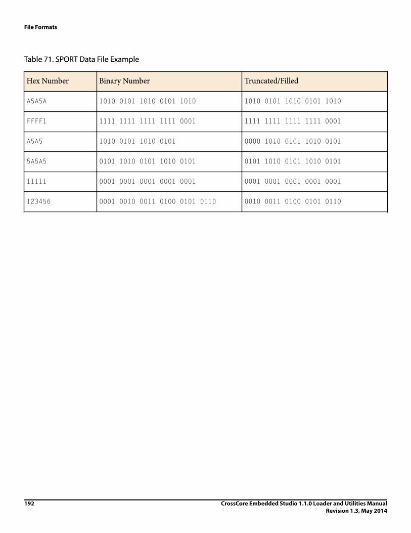
Table 71. SPORT Data File Example
Hex Number Binary Number Truncated/Filled
A5A5A 1010 0101 1010 0101 1010 1010 0101 1010 0101 1010
FFFF1 1111 1111 1111 1111 0001 1111 1111 1111 1111 0001
A5A5 1010 0101 1010 0101 0000 1010 0101 1010 0101
5A5A5 0101 1010 0101 1010 0101 0101 1010 0101 1010 0101
11111 0001 0001 0001 0001 0001 0001 0001 0001 0001 0001
123456 0001 0010 0011 0100 0101 0110 0010 0011 0100 0101 0110
File Formats
192 CrossCore Embedded Studio 1.1.0 Loader and Utilities ManualRevision 1.3, May 2014

12Utilities
CrossCore Embedded Studio includes several utility programs, some of which run from a command line only.
This appendix describes the following utilities.
• hexutil – Hex-32 to S-Record File Converter• elf2dyn – ELF to Dynamically-Loadable Module Converter• elf2elf – ELF to ELF File Converter• dyndump – Display the Contents of Dynamically-Loadable Modules• dynreloc – Relocate Dynamically-Loadable Modules• signtool – Sign and Encrypt boot streams for secure booting
Other CrossCore Embedded Studio utilities, for example, the ELF file dumper, are described in the Linker andUtilities Manual (search the online help).
xAttention:
VisualDSP++ executables are not upwardly compatible with CrossCore Embedded Studio executables.The ELF format has changed.
hexutil - Hex-32 to S-Record File ConverterThe hex-to-S file converter (hexutil.exe) transforms a loader (.ldr) file in Intel hexadecimal 32-bit format toMotorola S-record format or produces an unformatted data file.
Syntax
hexutil.exe is a command-line utility. It has the following syntax:
hexutil input_file [-s1|s2|s3|StripHex] [-o file_name]
where:
input_file is the name of the .ldr file generated by the CrossCore Embedded Studio splitter utility.
The hexutil Command-Line Switches table lists the optional switches used with the hexutil command.
Utilities
CrossCore Embedded Studio 1.1.0 Loader and Utilities ManualRevision 1.3, May 2014
193
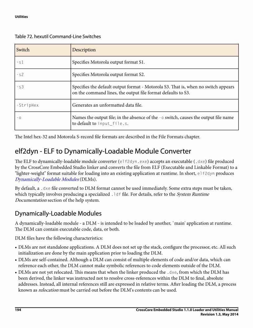
Table 72. hexutil Command-Line Switches
Switch Description
-s1 Specifies Motorola output format S1.
-s2 Specifies Motorola output format S2.
-s3 Specifies the default output format - Motorola S3. That is, when no switch appearson the command lines, the output file format defaults to S3.
-StripHex Generates an unformatted data file.
-o Names the output file; in the absence of the -o switch, causes the output file nameto default to input_file.s.
The Intel hex-32 and Motorola S-record file formats are described in the File Formats chapter.
elf2dyn - ELF to Dynamically-Loadable Module ConverterThe ELF to dynamically-loadable module converter (elf2dyn.exe) accepts an executable (.dxe) file producedby the CrossCore Embedded Studio linker and converts the file from ELF (Executable and Linkable Format) to a"lighter-weight" format suitable for loading into an existing application at runtime. In short, elf2dyn produces Dynamically-Loadable Modules (DLMs).
By default, a .dxe file converted to DLM format cannot be used immediately. Some extra steps must be taken,which typically involves producing a specialized .ldf file. For details, refer to the System RuntimeDocumentation section of the help system.
Dynamically-Loadable ModulesA dynamically-loadable module - a DLM - is intended to be loaded by another, `main' application at runtime.The DLM can contain executable code, data, or both.
DLM files have the following characteristics:
• DLMs are not standalone applications. A DLM does not set up the stack, configure the processor, etc. All suchinitialization are done by the main application prior to loading the DLM.
• DLMs are self-contained. Although a DLM can consist of multiple elements of code and/or data, which canreference each other, the DLM cannot make symbolic references to code elements outside of the DLM.
• DLMs are not yet relocated. This means that when the linker produced the .dxe, from which the DLM hasbeen derived, the linker was instructed not to resolve cross-references within the DLM to final, absoluteaddresses. Instead, all internal references still are expressed in relative terms. After loading the DLM, a processknown as relocation must be carried out before the DLM's contents can be used.
Utilities
194 CrossCore Embedded Studio 1.1.0 Loader and Utilities ManualRevision 1.3, May 2014

• DLMs export one or more symbols, which can be used by the main application to reference the contents of theDLM.
iNote:
Because of the noted differences, most .dxe files are not suitable for conversion to DLMs.
For information on how to construct .dxe files that can be converted to DLMs, load DLMs, and access DLMcontents, refer to the System Runtime Documentation section in help.
SyntaxThe elf2dyn.exe utility is invoked from the command-line or CCES IDE, as a post-build step specified in yourproject's Settings > Build Steps dialog box.
The command-line syntax for the utility is:
elf2dyn [-h|l|r|v] [-a name=num] [-e sym] [-S|R|W|E errnum] [-o outfile] elfinfile
where:
elfinfile is the name of the .dxe file in ELF format to convert into a DLM file for Blackfin or SHARCprocessors. The file name must appear at the end of the command line. In order to be useful as a DLM, it mustcontain relocations, as described in the System Runtime Documentation help section.
The elf2dyn Command-Line Switches table lists the optional switches used with the elf2dyn command.Switches must appear before elfinfile on the command line.
Table 73. elf2dyn Command-Line Switches
Switch Description
-h Displays a list of accepted switches.
-l Creates a `lite' format output file; see File Formats and the-l Switch.
-r Emits remarks (if any apply).
-v Emits version information.
-a name=num Forces section name to have alignment num; see Section Alignment.
-e symbol Exports symbol so that it can be referenced by the main application; see ExportedSymbols.
-o outfile Use outfile as the name of the DLM to create. The switch specifies whereelf2dyn creates the DLM file. If -o is omitted, elf2flt creates elfinfile.dyn,
Utilities
CrossCore Embedded Studio 1.1.0 Loader and Utilities ManualRevision 1.3, May 2014
195

Switch Description
which means that the output file has the same name as the input file with the .dynsuffix appended.
-S errnum Suppresses diagnostic errnum.
-R errnum Makes diagnostic errnum a remark.
-W errnum Makes diagnostic errnum a warning.
-E errnum Makes diagnostic errnum an error.
File Formats and -l Switchelf2dyn supports two formats, a full format and a lite format. By default, DLMs are created using the fullformat, the lite format can be enabled by specifying the -l switch.
Both ELF files and DLM files are divided into sections, some of which specify content which makes up the codeand/or data of the application, and some of which specify metadata about the code and/or data of theapplication. For example, the debug information of an application is used by a debugger, which controls theprocessor, but not downloaded to the processor by the debugger. For the purposes of this discussion, thefollowing sections use the terms application section and metadata section to make this distinction.
The lite format is closely modeled on the bFLT file format, which in turn is influenced by the UNIX a.out fileformat. It imposes the following constraints on the .dxe input file:
1. The ELF file must contain exactly three application sections with the following names and uses:
iNote:
The lite format is supported for Blackfin processors only because of the mentioned constraints.
• .text, which contains only executable code• .data, which contains only initialized data (initialized to any value)• .bss, which contains only zero-initialized data
2. All sections must contain 8-bit byte-addressed values.3. Exported symbols are impossible, so the code entry point must be the first instruction at the start of
the .text section, and any data entry point must be the first location at the start of the .data section.
In contrast, the full DLM format supports the following:
• The ELF file can have any number of application sections, from 1 to 255.• Application sections can have any valid section name.11
11 If exported symbols are being used, two names are reserved: .expsym and .expstr.
Utilities
196 CrossCore Embedded Studio 1.1.0 Loader and Utilities ManualRevision 1.3, May 2014

• Application sections can use any word size that is valid for the target processor. Note that not all sections needbe the same word size.
• Symbols may be exported, so that entry points need not be at the start of a particular section.
iNote:
The full DLM format is proprietary to Analog Devices, Inc. Although more complex than the bFLT-inspired lite format, it is still lighter than the full ELF standard.
Exported SymbolsThe -e switch specifies particular symbols for exporting. The symbol table of the ELF file is a metadata section,so it is not available to the application when the application runs. When a symbol is exported by elf2dyn, thesymbol is placed into an exported symbol table, which is in an application rather than a metadata section. Thismeans that the table is available to the running application, and the application can locate DLM contents bysearching for the symbol in the table.
The exported symbol table is two new application sections that are added to the DLM by elf2dyn when the -eswitch is being used:
• .expstr is the exported string table; it contains NULL-terminated strings which are the exported symbolnames. These strings are in the native target processor data format.
• .expsym is the exported symbol table; it contains one or more records, where each record consists of twopointers - to the symbol's name in the exported string table, and to the symbol's location in memory,respectively. Because the record contains pointers, the exported symbol table is only accessible once the DLMhas been relocated.
The -e switch accepts names exactly as they appear in the symbol table of the ELF input file elfinfile. Noname-demangling or parsing is done by elf2dyn. This means that, for example, to export your main() functionin your DLM, -e _main is used. If you are unsure how to specify a symbol's name for exporting, use thefollowing command:
elfdump -n .symtab elfinfile
The elfdump utility displays the contents of the ELF file's symbol table; elfdump shows both mangled anddemangled names. For more information, see dyndump – Display the Contents of Dynamically-LoadableModules.
After a DLM is loaded and resolved, you can map an exported symbol's name into its address usingdyn_LookupByName(). Refer to the System Runtime Documentation help section for details.
Section AlignmentBy default, the elf2elf utility creates a DLM in which each section has the same alignment constraints as theoriginal sections in the input ELF file. You can specify a stronger alignment for a section by using the -a switch.The-a switch requires a parameter of the form name=number, where:
• name is the name of the section in the input ELF file• number is a positive power-of-two decimal integer.
Utilities
CrossCore Embedded Studio 1.1.0 Loader and Utilities ManualRevision 1.3, May 2014
197

Multiple instances of the -a switch are permitted on the same command-line to specify stronger alignment formore than one section.
It is not an error if the input ELF file does not contain a section called name. If the input file does not have asection with a matching name, the switch is ignored.
elf2elf - ELF to ELF File ConverterThe ELF to ELF file converter (elf2elf.exe) is a command-line utility for upgrading executables built usingVisualDSP++ 5.0 to the new CrossCore Embedded Studio ELF format.
xAttention:
VisualDSP++ executables are not upwardly compatible to CrossCore Embedded Studio executables. TheELF format has changed.
The loaders and splitters take executable files in ELF format as input. These are files with the suffixes dxe, ovl, orsm. The CrossCore Embedded Studio loaders and splitters expect input in the CrossCore Embedded Studio ELFformat, which has significant differences from the VisualDSP++ ELF format.
You do not need to use elf2elf when:
• Creating new projects in the CrossCore Embedded Studio IDE• Importing VisualDSP++ legacy projects into the CrossCore Embedded Studio IDE and rebuilding all code
from source
In both cases, CrossCore Embedded Studio creates the executables in the expected ELF format.
The following unrecoverable error is reported by the CrossCore Embedded Studio loaders and splitters if anydxe/ovl/sm in the build is one built with VisualDSP++:
[Error ld0002]
File in legacy ELF format created with VisualDSP++ 5.0 or earlier.
Rebuild from source or upgrade using the elf2elf utility: <filename>
If you do not have sources to rebuild your code, the elf2elf utility is available.
Syntax
elf2elf.exe has the following syntax:
elf2elf [switches] [infile]
where:
infile is the name of the ELF input file produced by CrossCore Embedded Studio.
The elf2elf Command-Line Switches table shows the optional switches used with the elf2elf command.
Utilities
198 CrossCore Embedded Studio 1.1.0 Loader and Utilities ManualRevision 1.3, May 2014

Table 74. elf2elf Command-Line Switches
Switch Description
-o file Produces the output file with a name given by file.
-keep Prevents any temporary files that have been created by the ELF Conversion Toolfrom being deleted.
-merge
Merge the contents of the .ovl and .sm files specified in the input .dxe into theoutput .dxe.
-version Displays the version number of the ELF conversion utility.
Example: elf2elf.exe oldKernel.dxe -o newKernel.dxe
iNote:
If you are building loader files, do no use -merge; instead, do the following:
• Upgrade the .dxe file without -merge• Upgrade each .sm or .ovl file with elf2elf
dyndump - Display the Contents of Dynamically-Loadable ModulesTo display the contents of dynamically-loadable modules (DLMs) produced by elf2dyn.exe, use dyndump.exe.
Refer to elf2dyn – ELF to Dynamically-Loadable Module Converter for more information on elf2dyn.
Syntax
dyndump.exe is a command-line utility. It has the following syntax:
dyndump [-f family] dlmname
where:
dlmname is the name of a file generated by elf2dyn; see elf2dyn – ELF to Dynamically-Loadable ModuleConverter.
The dyndump Command-Line Switches table lists switches used with the dyndump command.
Table 75. dyndump Command-Line Switches
Switch Description
-f Family Select the target processor family; see -f family.
Utilities
CrossCore Embedded Studio 1.1.0 Loader and Utilities ManualRevision 1.3, May 2014
199

Switch Description
dlmname The file to be displayed; see Output.
-f FamilyThe dyndump utility can display files for both Blackfin and SHARC processors in full and lite DLM format. Thelite format files do not include any information indicating their target processor; without this information, thedyndump utility cannot decode the target-specific relocations section. See File Formats and the-l Switch for moreinformation.
The valid forms of the -f family switch are:
• -f blackfin• -f sharc
iNote:
Full-format DLM files do specify their target processor, so the -f switch is not necessary for displayingsuch files.
OutputThe dyndump utility displays the header from the input file, followed by the metadata sections and applicationsections, in the order they appear in the file. In general, dyndump displays information in several ways, providing:
• The offset within a section in the native addressing of that section• The byte offset from the start of the file• A hexadecimal dump of the bytes in the order they appear within the file. Each target address location in an
application is displayed on a separate line, so byte-addressed sections shows a single byte per line, while 64-bitaddressed sections shows eight bytes per line.
• An ASCII representation of the bytes in the order they appear within the file.
File headers, section headers (where present) and relocations are displayed more explicitly.
dynreloc - Relocate Dynamically-Loadable ModulesTo relocate DLMs produced by elf2dyn.exe, use dynreloc.exe.
Refer to elf2dyn – ELF to Dynamically-Loadable Module Converter for more information about elf2dyn.
The dynreloc utility reads a DLM file as input, performs relocations according to address mappings providedthrough command-line switches, and writes out a new DLM file. The new DLM file contains no relocations andcan be loaded only into the locations specified to the dynreloc utility.
Syntax dynreloc.exe is a command-line utility. It has the following syntax:
dynreloc [-h|v] [-a sec=addr] [-m a:n:w:m][-o outfile] infile
Utilities
200 CrossCore Embedded Studio 1.1.0 Loader and Utilities ManualRevision 1.3, May 2014
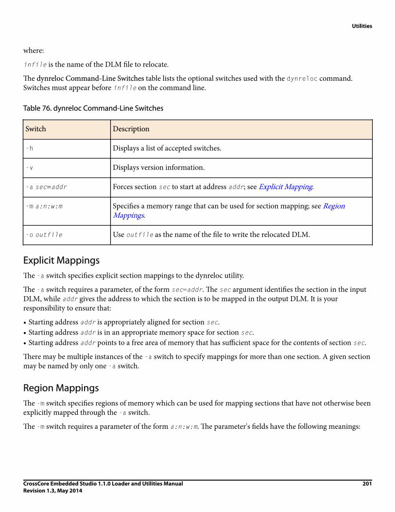
where:
infile is the name of the DLM file to relocate.
The dynreloc Command-Line Switches table lists the optional switches used with the dynreloc command.Switches must appear before infile on the command line.
Table 76. dynreloc Command-Line Switches
Switch Description
-h Displays a list of accepted switches.
-v Displays version information.
-a sec=addr Forces section sec to start at address addr; see Explicit Mapping.
-m a:n:w:m Specifies a memory range that can be used for section mapping; see RegionMappings.
-o outfile Use outfile as the name of the file to write the relocated DLM.
Explicit MappingsThe -a switch specifies explicit section mappings to the dynreloc utility.
The -a switch requires a parameter, of the form sec=addr. The sec argument identifies the section in the inputDLM, while addr gives the address to which the section is to be mapped in the output DLM. It is yourresponsibility to ensure that:
• Starting address addr is appropriately aligned for section sec.• Starting address addr is in an appropriate memory space for section sec.• Starting address addr points to a free area of memory that has sufficient space for the contents of section sec.
There may be multiple instances of the -a switch to specify mappings for more than one section. A given sectionmay be named by only one -a switch.
Region MappingsThe -m switch specifies regions of memory which can be used for mapping sections that have not otherwise beenexplicitly mapped through the -a switch.
The -m switch requires a parameter of the form a:n:w:m. The parameter's fields have the following meanings:
Utilities
CrossCore Embedded Studio 1.1.0 Loader and Utilities ManualRevision 1.3, May 2014
201
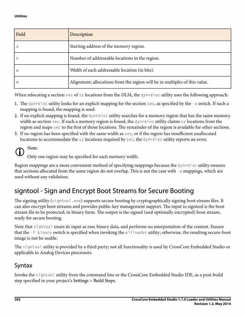
Field Description
a Starting address of the memory region.
n Number of addressable locations in the region.
w Width of each addressable location (in bits).
m Alignment; allocations from the region will be in multiples of this value.
When relocating a section sec of sz locations from the DLM, the dynreloc utility uses the following approach:
1. The dynreloc utility looks for an explicit mapping for the section sec, as specified by the -a switch. If such amapping is found, the mapping is used.
2. If no explicit mapping is found, the dynreloc utility searches for a memory region that has the same memorywidth as section sec. If such a memory region is found, the dynreloc utility claims sz locations from theregion and maps sec to the first of those locations. The remainder of the region is available for other sections.
3. If no region has been specified with the same width as sec, or if the region has insufficient unallocatedlocations to accommodate the sz locations required by sec, the dynreloc utility reports an error.
iNote:
Only one region may be specified for each memory width.
Region mappings are a more convenient method of specifying mappings because the dynreloc utility ensuresthat sections allocated from the same region do not overlap. This is not the case with -a mappings, which areused without any validation.
signtool - Sign and Encrypt Boot Streams for Secure BootingThe signing utility (signtool.exe) supports secure booting by cryptographically signing boot stream files. Itcan also encrypt boot streams and provides public-key management support. The input to signtool is the bootstream file to be protected, in binary form. The output is the signed (and optionally encrypted) boot stream,ready for secure booting.
Note that signtool treats its input as raw, binary data, and performs no interpretation of the content. Ensurethat the -f binary switch is specified when invoking the elfloader utility; otherwise, the resulting secure-bootimage is not be usable.
The signtool utility is provided by a third party; not all functionality is used by CrossCore Embedded Studio orapplicable to Analog Devices processors.
SyntaxInvoke the signtool utility from the command line or the CrossCore Embedded Studio IDE, as a post-buildstep specified in your project's Settings > Build Steps.
Utilities
202 CrossCore Embedded Studio 1.1.0 Loader and Utilities ManualRevision 1.3, May 2014

The command-line syntax for the signtool utility is:
signtool cmd switches
cmd indicates the kind of operation to perform (the choices are described in the following sections). switchesare dependent on the choice of cmd.
Output FormatsWhen signing or encrypting a file, signtool generates output in one of several forms, depending on whetherencryption is required, and delivers the encryption key to the processor for decryption. The different outputformats are known by the abbreviations BLp, BLx, BLw, and BLe.
• The BLp format supports signing, not encryption. The output file includes a signature produced by a 224-bitElliptic Curve Digital Signature Algorithm (ECDSA) private key. The corresponding public key must beseparately programmed into the processor's OTP to allow the target processor to authenticate the boot stream.
• The BLx format supports signing and encryption. The output file is signed, as per the BLp format. It is alsoencrypted using an AES-128 key. The encryption key is not part of the output file, so it must be programmedinto the processor's OTP to allow the target processor to decrypt the boot stream.
• The BLw format supports signing and encryption. The output file is signed, as per the BLp format. It is alsoencrypted using an AES-128 key as per the BLx format, but unlike BLx, the encryption key is also included inthe output file, itself encrypted by a second AES-128 key (the "wrap" key). The wrap key must be programmedinto the processor's OTP to allow the target processor to decrypt the encryption key, which then allows theprocessor to decrypt the boot stream.
• The BLe format is only intended for testing, and should not be used for production systems. It supportsauthentication and encryption, but the encryption key is included in the output file as-is, without anyprotection.
Key Generation for SigningBoot stream files are signed using the private key from a 224-bit Elliptic Curve Digital Signature Algorithm(ECDSA) keypair, stored in DER format. The signtool utility's own genkeypair command can be used tocreate such a keypair. The following table describes the switches available for the genkeypair command.
The following is an example command for creating a keypair:
signtool genkeypair -algo ecdsa224 -outfile keychain.der
iNote:
Ensure you keep your keypair safe, once you have created it, and keep it secret, as the private key thereinis essential for authenticity.
Switch Description
Utilities
CrossCore Embedded Studio 1.1.0 Loader and Utilities ManualRevision 1.3, May 2014
203

Key Generation for EncryptionBoot stream files are encrypted using 128-bit keys, via the AES-128 algorithm. This is a symmetric algorithm,meaning that the same key is used for encryption and decryption. The signtool utility does not provide built-insupport for generating AES-128 keys; you can create any 16-character file and use that as your AES-128 key.Ensure that you keep the key secret.
Signing and Encrypting Boot StreamsBoot streams are signed using the private key from a 224-bitElliptic Curve Digital Signature Algorithm (ECDSA)keypair, by invoking the sign command of the signtool utility. The following table lists the switches that arerelevant to the sign command.
Switch Description
The following is an example of signing a boot stream file:
signtool sign -type BLp -prikey keychain.der -infile boot.bin -outfile secboot.bin
The following is an example of signing and encrypting a boot stream file, where a random encryption key isgenerated by signtool:
signtool sign -type BLw -prikey keychain.def -wrapkey aes.bin \\-infile boot.bin -outfile secboot.bin
Extracting Public KeysWhen a processor boots using secure boot, it must authenticate the boot stream before processing it. The bootstream will have been signed using the private key from a keypair; the authentication is done using thecorresponding public key from the same keypair. Use signtool's getkey command to extract the public key sothat you can store it in OTP on the processor, where it can be used during secure boot.
The switches relevant to the getkey command are listed in the table below.
The following is an example of extracting the public key in binary form:
signtool getkey -type BLKey -key keychain.der -outfile pubkey.bin
The following is an example of extracting the public key as a C header file, suitable for inclusion into anapplication:
signtool getkey -type BLKeyC -key keychain.der -outfile pubkey.h
Utilities
204 CrossCore Embedded Studio 1.1.0 Loader and Utilities ManualRevision 1.3, May 2014

Index
-64 splitter switch 176-a name=num switch (elf2dyn utility) 195-a sec=addr switch (dynreloc utility) 201-b prom|flash|spi|spislave|UART|TWI|FIFO, loader switch for ADSP-BF53x processors 72-b prom|flash|spi|spislave|UART|TWI|FIFO|OTP|NAND, loader switchfor ADSP-BF51x/52x/54x processors 31, 33-bprom|host|link|JTAG, loader switch for ADSP-21160 processors 113-bprom|host|link|spi, loader switch for ADSP-21161 processors 133-bprom|spislave|spiflash|spimaster|spiprom, loader switch forADSP-2126x/36x/37x/46x processors 146, 166-callback, loader switch for Blackfin 34-compression
loader switch for Blackfin 67, 73loader switch for SHARC 161, 164, 166
-compressionOverlay, loader switch for SHARC 162, 164, 167-compressWS
loader switch for Blackfin 71loader switch for SHARC 165, 167
-compressWS # 73-CRC32, loader switch for Blackfin 34, 87, 94-dm, splitter switch 176-dmawidth #, loader switch for Blackfin 34, 73-e filename, loader switch for ADSP-21160 processors 113-e symbol switch (elf2dyn utility) 195, 197-efilename, loader switch for SHARC 133-enc dll_filename, loader switch for Blackfin 73-f {hex|ascii|binary|include} 74-f family switch (elf2dlm utility) 199-f h|s1|s2|s3|b, splitter switch 176-f hex|ascii|binary|include, loader switch for Blackfin 34-fhex|ascii|binary|byte|include|s1|s2|s3, loader switch for SHARC 167-fhex|ascii|binary|include|s1|s2|s3, loader switch for SHARC 114, 133-FillBlock, loader switch for Blackfin 31, 34, 189-ghc #, loader switch for Blackfin 74-h switch
dynreloc utility 201elf2dyn utility 195
-h|helploader switch for Blackfin 35, 74loader switch for SHARC 114, 134, 167
-hostwidth #, loader switch for SHARC 134, 145, 146, 153, 154, 167-id#exe=filename
loader switch for SHARC 111, 114, 134, 168-id#exe=N, loader switch for SHARC 134-id#ref=N, loader switch for SHARC 114, 168-init filename, loader switch for Blackfin 35, 39, 41, 49, 65, 74, 78-initcall, ADSP-BF52x/54x Blackfin loader switch 35, 41-kb prom|flash|spi|spislave|UART|TWI|FIFO, loader switch for Blackfin75-kb prom|flash|spi|spislave|uart|twi|fifo|otp|nand, loader switch forBlackfin 36-keep switch (elf2elf utility) 199-kenc dll_filename, loader switch for Blackfin 75-kf #, loader switch for Blackfin 37-kf hex|ascii|binary|include, loader switch for Blackfin 75-kp #, loader switch for Blackfin 37, 39, 76, 78-kwidth #, loader switch for Blackfin 37, 76-l switch (elf2dyn utility) 195, 196-l userkernel
loader switch for Blackfin 37, 65loader switch for SHARC 115, 134, 149, 165, 168
-m switch (dynreloc utility) 201-M, loader switch for Blackfin 38, 76, 77-maskaddr #, loader switch for Blackfin 38, 76-MaxBlockSize #, loader switch for Blackfin 38, 76, 88, 95-MaxFillBlockSize #, loader switch for Blackfin 38-MaxZeroFillBlockSize #, loader switch for Blackfin 77, 88, 95-merge switch (elf2elf utility) 199-MM, loader switch for Blackfin 38, 77-Mo filename, loader switch for Blackfin 38, 77-Mt filename, loader switch for Blackfin 38, 77-NoFillBlock, loader switch for Blackfin 31, 38-nofinalblock, loader switch for Blackfin 77-nofinaltag, loader switch
ADSP-BF561 processors 77ADSP-BF60x processors 86
-noinitcode, loader switch for Blackfin 39, 77-nokernel
loader switch for ADSP-2126x/36x/37x/46x processors 169-norom, splitter switch 176-nosecondstageloader, loader switch for Blackfin 77-nozeroblock, loader switch for SHARC 135, 169-o filename
dynreloc utility switch 201elf2dyn utility switch 195elf2elf utility switch 199loader switch for Blackfin 39, 77loader switch for SHARC 115, 135, 169splitter switch 176
-o2, loader switch for Blackfin 36, 37, 39, 75, 78-p #, loader switch for Blackfin 39, 78-paddress, loader switch for SHARC 115, 135, 169-pflag {#|PF#|PG#|PH#}, loader switch for Blackfin 78-pflag #|PF|PG|PH #, loader switch for Blackfin 79–81-pm splitter switch 176-proc part_number
Index

loader switch for Blackfin 39, 78loader switch for SHARC 115, 135, 169splitter switch 177
-quickboot, loader switch for Blackfin 39-r #, splitter switch 177-ram, splitter switch 176, 177-readall, loader switch for Blackfin 40-retainSecondStageKernel, loader switch for SHARC 170-romsplitter, loader switch for Blackfin 38, 40, 76, 78-s section_name, splitter switch 177-save section, loader switch for Blackfin 40-ShowEncryptionMessage, loader switch for Blackfin 79-si-revision none|any|x.x
loader switch 178loader switch for Blackfin 41, 79loader switch for SHARC 115, 135, 170
-t#, loader switch for SHARC 115, 135-u
loader switch for SHARC 171-u, splitter switch 178-use32bitTagsforExternal Memory Blocks, loader switch for SHARC 115-v (verbose)
loader switch for Blackfin 41, 79loader switch for SHARC 116, 135, 170
-v switchdynreloc utility 201elf2dyn utility 195
-versionelf2elf utility switch 199loader switch for SHARC 116, 136, 170splitter switch 178
-width #, loader switch for Blackfin 41, 76, 79-zeroPadForced #, loader switch for Blackfin 79.asm (assembly) source files 19, 180.bss files (DLM format) 196.dat (data) initialization files 180.data files (DLM format) 196.dlb (library) files 182.doj (object) files 182.dxe (executable) files 23, 25, 182, 191.h_# (Intel hex-32) file format 175, 176, 183, 189.knl (kernel code) files 25.ldr (loader output) files
ASCII format 181, 191binary format 185, 188hex-32 format 183include format files 185naming 39, 77specifying host bus width 134, 167
.map (memory map) files 182
.s_# (Motorola S-record) files 175, 186, 191
.sm (shared memory) files 25, 113, 133, 182, 191
.stk (byte-stacked) files 175, 176, 178, 189
.text files (DLM lite format) 196
.txt (ASCII text) files 181
.VAR directive 180
16- to 48-bit word packing 1054- to 48-bit word packing 10648- to 8-bit word packing 1048- to 48-bit word packing 104, 105, 120, 122
AACK pin 103, 104, 121ADDR23-0 address lines 122address records, linear format 183ADSP-21160 processors
ADSP-21160 boot modes 99, 102boot sequence 100
ADSP-21161 processorsboot modes 117, 119boot sequence 118multiprocessor support 130
ADSP-2126x/36x/37x/46x processorsboot modes 137, 142boot sequence 138
ADSP-2136x/37x/4xx processors, multiprocessor support 159ADSP-BF50x processors
boot modes 28multi-dxe loader files 41
ADSP-BF51x processorsboot modes 29multi-dxe loader files 41
ADSP-BF52x/54x processorsboot modes 29multi-dxe loader files 41
ADSP-BF531/2/3/4/6/7/8/9 processorsADSP-BF534/6/7 (only) boot modes 45boot modes 44boot streams 47, 48compression support 67memory ranges 55multi-dxe loader files 64, 65on-chip boot ROM 44, 46, 47, 55, 65
ADSP-BF561 processorsboot modes 57boot streams 58–63dual-core architecture 56memory ranges 64multi-dxe loader files 64, 65multiprocessor support 63on-chip boot ROM 56, 57, 63–65
ADSP-BF60x processorsBCODE field 85boot modes 84
ADSP-BF70x processorsBCODE field 92boot modes 92
application loading (Blackfin processors)ADSP-BF531/2/3/4/6/7/8/9 processors 50, 66ADSP-BF561 processors 57, 64, 66
application loading (SHARC processors)ADSP-21161 processors 118, 120, 122ADSP-2126x/36x/37x processors 156ADSP-2126x/36x/37x/46x processors 138
Index
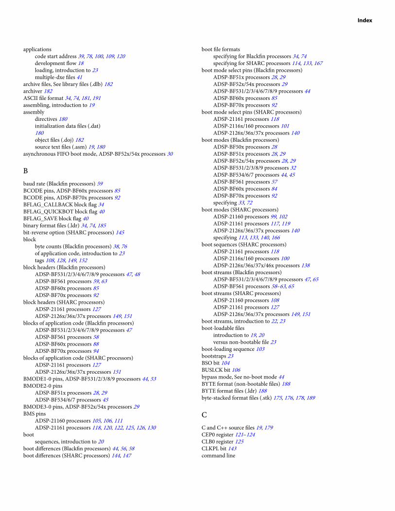
applicationscode start address 39, 78, 100, 109, 120development flow 18loading, introduction to 23multiple-dxe files 41
archive files, See library files (.dlb) 182archiver 182ASCII file format 34, 74, 181, 191assembling, introduction to 19assembly
directives 180initialization data files (.dat)180object files (.doj) 182source text files (.asm) 19, 180
asynchronous FIFO boot mode, ADSP-BF52x/54x processors 30
Bbaud rate (Blackfin processors) 59BCODE pins, ADSP-BF60x processors 85BCODE pins, ADSP-BF70x processors 92BFLAG_CALLBACK block flag 34BFLAG_QUICKBOT block flag 40BFLAG_SAVE block flag 40binary format files (.ldr) 34, 74, 185bit-reverse option (SHARC processors) 145block
byte counts (Blackfin processors) 38, 76of application code, introduction to 23tags 108, 128, 149, 152
block headers (Blackfin processors)ADSP-BF531/2/3/4/6/7/8/9 processors 47, 48ADSP-BF561 processors 59, 63ADSP-BF60x processors 85ADSP-BF70x processors 92
block headers (SHARC processors)ADSP-21161 processors 127ADSP-2126x/36x/37x processors 149, 151
blocks of application code (Blackfin processors)ADSP-BF531/2/3/4/6/7/8/9 processors 47ADSP-BF561 processors 58ADSP-BF60x processors 88ADSP-BF70x processors 94
blocks of application code (SHARC processors)ADSP-21161 processors 127ADSP-2126x/36x/37x processors 151
BMODE1-0 pins, ADSP-BF531/2/3/8/9 processors 44, 53BMODE2-0 pins
ADSP-BF51x processors 28, 29ADSP-BF534/6/7 processors 45
BMODE3-0 pins, ADSP-BF52x/54x processors 29BMS pins
ADSP-21160 processors 105, 106, 111ADSP-21161 processors 118, 120, 122, 125, 126, 130
bootsequences, introduction to 20
boot differences (Blackfin processors) 44, 56, 58boot differences (SHARC processors) 144, 147
boot file formatsspecifying for Blackfin processors 34, 74specifying for SHARC processors 114, 133, 167
boot mode select pins (Blackfin processors)ADSP-BF51x processors 28, 29ADSP-BF52x/54x processors 29ADSP-BF531/2/3/4/6/7/8/9 processors 44ADSP-BF60x processors 85ADSP-BF70x processors 92
boot mode select pins (SHARC processors)ADSP-21161 processors 118ADSP-2116x/160 processors 101ADSP-2126x/36x/37x processors 140
boot modes (Blackfin processors)ADSP-BF50x processors 28ADSP-BF51x processors 28, 29ADSP-BF52x/54x processors 28, 29ADSP-BF531/2/3/8/9 processors 32ADSP-BF534/6/7 processors 44, 45ADSP-BF561 processors 57ADSP-BF60x processors 84ADSP-BF70x processors 92specifying 33, 72
boot modes (SHARC processors)ADSP-21160 processors 99, 102ADSP-21161 processors 117, 119ADSP-2126x/36x/37x processors 140specifying 113, 133, 140, 166
boot sequences (SHARC processors)ADSP-21161 processors 118ADSP-2116x/160 processors 100ADSP-2126x/36x/37x/46x processors 138
boot streams (Blackfin processors)ADSP-BF531/2/3/4/6/7/8/9 processors 47, 65ADSP-BF561 processors 58–63, 65
boot streams (SHARC processors)ADSP-21160 processors 108ADSP-21161 processors 127ADSP-2126x/36x/37x processors 149, 151
boot streams, introduction to 22, 23boot-loadable files
introduction to 19, 20versus non-bootable file 23
boot-loading sequence 103bootstraps 23BSO bit 104BUSLCK bit 106bypass mode, See no-boot mode 44BYTE format (non-bootable files) 188BYTE format files (.ldr) 188byte-stacked format files (.stk) 175, 176, 178, 189
CC and C++ source files 19, 179CEP0 register 121–124CLB0 register 125CLKPL bit 143command line
Index

loader for SHARC processors 112, 132, 165loader/splitter for Blackfin processors 32, 72, 112, 132splitter 173, 175
compilation, introduction to 19compressed block headers
Blackfin processors 50, 68SHARC processors 163
compressed streamsBlackfin processors 67, 70SHARC processors 162, 164
compression supportADSP-BF531/2/3/4/6/7/8/9 processors 67
compression window 69, 71, 163, 165conversion utilities 193, 194, 199count headers (Blackfin processors)
ADSP-BF531/2/3/4/6/7/8/9 processors 65ADSP-BF561 processors 59, 63, 65
CPEP0 register 121, 123CPHASE bit 143CPLB0 register 125CRC32 protection, ADSP-BF60x processors 87CRC32 protection, ADSP-BF70x processors 94CS pin 105, 124, 142CSRX register 126Cx register 103, 104, 107
DD39-32 bits 104data
initialization files (.dat) 180memory (dm) sections 174, 176
data banks (Blackfin processors)ADSP-BF531/2/3/4/6/7/8/9 processors 55ADSP-BF561 processors 64
data packing (SHARC processors)ADSP-21160 processors 104–106ADSP-21161 processors 120, 122ADSP-2126x/36x/37x/46x processors 141, 153, 154
data streamsencrypting from application 73encrypting from kernel 75
DATA23-16 pins 120DATA39-32 pins 102DATA63-32 pins 105DATA64 memory sections 174, 176DataFlash devices 44debugger file formats 19, 191debugging targets 19decompression
initialization files 71kernel files 165
DEN register 121, 123DLMs to ELF DLM converter 199DMA (ADSP-21160 processors)
buffers 105channel control registers 104–107channel interrupts 106, 107channel parameter registers 103–105, 107controller 99, 103, 104transfers 104–107, 109
DMA (ADSP-21161 processors)buffers 131channel control registers 120, 122, 123, 127channel interrupts 122, 124channel parameter registers 121–127controller 120–122transfers 118, 122, 126, 127, 130
DMA (ADSP-2126x/36x/37x/46x processors)parameter registers 143transfers 147
DMA (ADSP-2126x/36x/37x/46x processors): code example 156DMA (ADSP-2126x/36x/37x/46x processors): parameter registers 156DMAC0 channel (ADSP-21160 processors) 105DMAC10 channels
ADSP-21160 processors 100, 103–105, 107ADSP-21161 processors 120–122
DMAC6 channel (ADSP-21160 processors) 104, 105, 107DMAC8 channels
ADSP-21160 processors 105, 106ADSP-21161 processors 118, 124–126
DMISO bit 143DTYPE register 105, 121, 124dual-core applications
ADSP-BF561 processors 63ADSP-BF60x processors 86
DWARF-2 debugging information 19Dynamically Loadable Modules (DLMs) 194dyndump utility 199dynreloc utility 200
EEBOOT pins
ADSP-21160 processors 101, 102, 105, 106ADSP-21161 processors 118, 120, 122, 125, 126, 131
ECEP0 register 121–123ECx register 103–105EIEP0 register 121, 123EIx register 103, 105ELF to BFLT file converter 198elf to DLM converter 194elf2dyn utility 194, 195elf2flt utility 198elfdump utility 197elfloader, See loaderEMEP0 register 121, 123EMx register 103encrypted images, ADSP-BF70x processors 93encryption functions 73, 75, 79end-of-file records 184EP0I vector 106, 122, 124EPB0 buffer 105EPROM boot mode (SHARC processors)
Index
ADSP-21160 processors 99, 101, 102, 111, 112ADSP-21161 processors 117, 118, 120multiprocessor systems 130
EPROM flash memory devices 22executable and linkable format (ELF)
executable files (.dxe) 19, 20, 182object files (.doj) 182
exported symbols 197external
memory boot 20resistors 103vector tables 111
external memory (Blackfin processors)ADSP-BF531/2/3/4/6/7/8/9 processors 44, 45, 65ADSP-BF561 processors 63, 65multiprocessor support 65
external memory (SHARC processors)ADSP-21160 processors 102, 104, 106, 107, 109, 111, 115ADSP-21161 processors 119, 127, 130, 135ADSP-2126x/36x/37x processors) 153ADSP-2126x/36x/37x/46x processors 141
external ports (SHARC processors)ADSP-21160 processors 101, 102, 104–107, 109, 111ADSP-21161 processors 118, 120–124, 131
Ffile formats
ASCII 34, 74, 191binary 34, 74byte-stacked (.stk) 175, 176, 178debugger input files 191hexadecimal (Intel hex-32) 34, 74, 175, 176include 34, 74list of 24s-record (Motorola) 175, 176
file formattingselecting for output 37, 75specifying word width 79
file search rules 24final blocks
introduction to 23SHARC processors 109, 149, 155
FLAG pins, ADSP-21160 processors 111flag words (Blackfin processors)
ADSP-BF531/2/3/4/6/7/8/9 processors 49ADSP-BF561 processors 59, 63
flash memoryADSP-BF51x processors 29ADSP-BF52x/54x processors 29devices 19
FLG0 signal 143frequency 106, 125
Gglobal header structures, See block headers 58, 59, 74GPEP0 register 121, 123GPLB0 register 125GPSRX register 126
HHBG pin 105HBR pin 124header files (.h) 58, 181header records
byte-stacked format (.stk) 190s-record format (.s_#) 186
hex-to-S converter 193hexutil utility 193hold time cycles 59host boot mode (SHARC processors)
ADSP-21160 processors 99, 105, 111ADSP-21161 processors 117, 122ADSP-2126x/36x/37x/46x processors 147
host boot mode, introduction to 22, 23host DMA boot mode, ADSP-BF52x/54x processors 30HPM bit 105
IIDLE instruction 101, 106, 109, 110, 123ignore blocks (Blackfin processors)
ADSP-BF531/2/3/4/6/7/8/9 processors 49ADSP-BF561 processors 59
IIEP0 register 121, 123IILB0 register 125IISRX register 126IIVT bit 111, 130IIx register 103, 107image files, See PROM, non-bootable files 173IMASK register 106, 107IMDW register 106, 156IMEP0 register 121, 123IMLB0 register 125IMSRX register 126IMx register 103include file format 185INIT_L16 blocks 154INIT_L48 blocks 153INIT_L64 blocks 155initial word option (SHARC processors) 145initialization blocks (ADSP-2126x/36x/37x/46x processors) 151, 153–156initialization blocks (Blackfin processors)
ADSP-BF531/2/3/4/6/7/8/9 processors 49, 50, 66ADSP-BF561 processors 63, 64, 66
initialization blocks (Blackfin processors): code example 51, 66input file formats, See source file formats 179input files
executable (.dxe) files 25, 112, 132, 165extracting memory sections from 176, 177
instruction SRAM (Blackfin processors)
Index

ADSP-BF531/2/3/4/6/7/8/9 processors 55ADSP-BF561 processors 63, 64
Intel hex-32 file format 31, 34, 74, 183internal memory, boot-loadable file execution 20interrupt vector location 122, 124interrupt vector tables 111, 130, 149, 156IOP registers 105IRQ vector 103IVG15 lowest priority interrupt 46, 50, 58
Kkernels (ADSP-21160 processors)
boot sequence 100, 107default source files 107, 110loading to processor 104, 106modifying 109rebuilding 110replacing with application code 109specifying user kernel 115
kernels (ADSP-21161 processors)boot sequence 118default source files 127, 129modifying 128, 129rebuilding 128, 129
kernels (ADSP-2126x/36x/37x/46x processors)boot sequence 138, 147compression/decompression 161, 162, 164, 165default source files 147loading to processor 143, 144modifying 148, 150omitting in output 149rebuilding 150
kernels (Blackfin processors)compression/decompression 67, 70specifying boot mode 36, 75specifying file format 37, 75specifying file width 76specifying hex address 37, 76specifying user kernel 37
LL1 memory (Blackfin processors)
ADSP-BF531/2/3/4/6/7/8/9 processors 47, 50, 55ADSP-BF561 processors 58, 64
L2 memory (Blackfin processors)ADSP-BF561 processors 64
last blocks (Blackfin processors)ADSP-BF531/2/3/4/6/7/8/9 processors 50, 51ADSP-BF561 processors 59
LBOOT pinsADSP-21161 processors 101, 102, 105, 118, 120, 122, 125, 126
LCOM register 107LCTL register 107, 109, 125least significant bit first (LSB) format 144library files (.dlb) 182link buffers 106, 107, 124, 125link port boot mode
ADSP-2146x SHARC processors 166link port boot mode (SHARC processors)
ADSP-21160 processors 99, 101ADSP-21161 processors 117, 119, 124
linkercommand-line files (.txt) 181memory map files (.map) 182output files (.dxe, .sm, .ovl) 19, 182
linking, introduction to 19loadable files, See boot-loadable files 19loader
operations 20output file formats 21, 23, 183, 185, 186, 188
loader for ADSP-21160 processors 99loader for ADSP-21161 processors 117loader for ADSP-2126x/36x/37x/469 processors 137loader for ADSP-BF51x/52x/54x Blackfin (includes splitter) 27loader for ADSP-BF53x/BF561 Blackfin (includes splitter) 43loader for ADSP-BF60x Blackfin (includes splitter) 83loader for ADSP-BF70x Blackfin (includes splitter) 91loader kernels, See boot kernels 23loader switches, See switches by name 33, 72loading, introduction to 19
Mmake files 38, 76, 77masking EPROM address bits 38, 76master (host) boot, introduction to 20memory map files (.map) 182memory programming on ADSP-BF60x processors 87memory ranges (Blackfin processors)
ADSP-BF531/2/3/4/6/7/8/9 processors 55ADSP-BF561 processors 64
microcontroller data transfers 189MODE1 register 106MODE2 register 106most significant bit first (MSB) format 144Motorola S-record file format 186MS bit 143MSBF bit 143MSWF register 121, 124multiprocessor booting, introduction to 20multiprocessor systems (Blackfin processors) 41, 65multiprocessor systems (SHARC processors)
ADSP-21160 processors 112ADSP-21161 processors 120, 130, 131
Nno-boot mode
introduction to 20, 22selecting with -romsplitter switch 40, 78
no-boot mode (Blackfin processors)ADSP-BF50x processors 28ADSP-BF51x processors 29ADSP-BF52x/54x processors 29ADSP-BF531/2/3/4/6/7/8/9 processors 44ADSP-BF561 processors 58
Index

no-boot mode (SHARC processors)ADSP-21160 processors 99, 107ADSP-21161 processors 117, 119, 127
non-bootable filescreating from command line 174ignoring ROM sections 176introduction to 20, 23specifying format 176specifying name 176specifying word width 174, 177
non-bootable output files 188NOP instruction 101, 106, 109, 110, 123numeric formats 180
Oobject files (.doj) 182on-chip boot ROM
ADSP-BF531/2/3/4/6/7/8/9 processors 23, 44, 46, 47, 49, 55, 65ADSP-BF561 processors 56, 57, 63–65introduction to 23
OTP boot mode, ADSP-BF51x/52x/54x processors 29output files
generating kernel and application 39, 78specifying format 21, 182specifying name 39, 77specifying with -o switch 194specifying word width 79, 134
overlay compression 164overlay memory files (.ovl) 25, 182, 191
Ppacking boot data 117parallel/serial PROM devices 22PFx signals 78pin
ACK 105PMODE register 104, 105, 121, 124processor IDs
assigning to .dxe file 114, 134, 168pointing to jump table 114, 134
processor type bits (Blackfin boot streams) 49processor-loadable files, introduction to 22program counter settings (ADSP-21160 processors) 105program development flow 18program memory sections (splitter) 174, 176PROM
boot mode, introduction to 22downloading boot-loadable files 20memory devices 147, 183
PROM (image) filescreating from command line 174ignoring ROM sections 176specifying format 176specifying name 176specifying width 177
PROM boot mode, ADSP-2126x/36x/37x/46x processors 141, 150PROM/flash boot mode (Blackfin processors)
ADSP-BF531/2/3/4/6/7/8/9 processors 44, 45, 66ADSP-BF561 processors 63, 66
pull-up resistors 121Px register 109, 156
RRBAM bit 121RBWS bit 121RD pin 104, 122reset
ADSP-21160 processors 100, 103–105, 107ADSP-21161 processors 118, 120–123, 125, 126ADSP-2126x/36x/37x/46x processors 138, 148ADSP-BF561 processors 53, 56, 58Blackfin processors 28, 43, 44dual-core Blackfin processors 56processor, introduction to 22, 23vector addresses 100, 104, 106, 129vector routine 122
RESETinterrupt service routine 46, 58, 124pin 103, 121
RESET pin 124reset: vector routine 55ROM
memory images as ASCII text files 191memory sections 176
Rx registers 63, 66, 106
Ss1 (Motorola EXORciser) file format 176, 186s2 (Motorola EXORMAX) file format 176, 186s3 (Motorola 32-bit) file format 176, 186scratchpad memory (Blackfin processors)
ADSP-BF561 processors 64SDCTL register 129SDRAM memory (ADSP-21160 processors) 107SDRAM memory (Blackfin processors)
ADSP-BF531/2/3/4/6/7/8/9 processors 49, 56ADSP-BF561 processors 63, 64
SDRAM memory (Blackfin processors): ADSP-BF531/2/3/4/6/7/8/9processors 51SDRAM/DDR boot mode, ADSP-BF52x/54x processors 30SDRDIV register 129second-stage loader
ADSP-BF561 processors 63secure boot, ADSP-BF70x processors 93SENDZ bit 143sequential EPROM boot 131shared memory
Index
Blackfin processors 63, 64file format (.sm) 25, 63, 182, 191in compressed .ldr files 162, 164omitting from loader file 113, 133
shift register, See RX registers 142simulators, for boot simulation 20single-processor systems 112, 131, 174slave processors 20, 22, 143software reset 22, 47, 58source file formats
assembly text (.asm) 180C/C++ text (.c, .cpp, .cxx) 179
SPI boot modes (SHARC processors)ADSP-21161 processors 117, 119, 125ADSP-2126x/36x/37x/46x processors 142, 145, 150
SPI EEPROM boot mode (Blackfin processors)ADSP-BF561 processors 63
SPI flash boot mode (ADSP-2126x/2136x/2137x/21469 processors) 147SPI host boot mode (ADSP-2126x/36x/37x/46x processors) 147SPI master boot modes
ADSP-2126x/36x/37x processors 149ADSP-2126x/36x/37x/46x processors 143, 145ADSP-BF51x processors 29ADSP-BF52x/54x processors 30ADSP-BF531/2/3/8/9 processors 44ADSP-BF534/6/7 processors 30, 45ADSP-BF60x processors 85ADSP-BF70x processors 92
SPI memory slave devices 144SPI PROM boot mode (ADSP-2126x/36x/37x/46x processors) 145–147SPI slave boot mode (ADSP-2126x/2136x/2137x/21469 processors) 143SPI slave boot mode (ADSP-2126x/36x/37x/46x processors) 142, 145SPI slave boot mode (Blackfin processors)
ADSP-BF51x processors 29ADSP-BF52x/54x processors 30ADSP-BF531/2/3/8/9 processors 44ADSP-BF534/6/7 processors 45
SPICLK register 143, 144, 147SPICTL register 126SPIDS signal 143SPIEN bit 143SPIRCV bit 143SPIRx register 118, 125, 126splitter
command-line syntax 173file extensions 175introduction to 19–22list of switches 175output file formats 189, 191
SPORT hex data files 191SRAM memory (Blackfin processors)
ADSP-BF531/2/3/4/6/7/8/9 processors 55ADSP-BF561 processors 57, 64
start addressesADSP-21160 application code 100Blackfin application code 39, 78
status information 41, 79supervisor mode (Blackfin processors)
ADSP-BF531/2/3/4/6/7/8/9 processors 46ADSP-BF561 processors 58
synchronous boot operations 105SYSCON register (SHARC processors)
ADSP-21160 processors 105, 109, 111ADSP-21161 processors 129, 130
SYSCR register (Blackfin processors)ADSP-BF531/2/3/4/6/7/8/9 processors 47ADSP-BF561 processors 58
SYSCTL register 156SYSTAT register 111system reset configuration register, See SYSCR register 28, 43
Ttermination records 187text files 191Tool Settings dialog box 32, 71, 88, 95, 112, 131, 149, 165two-wire interface (TWI) boot mode
ADSP-BF2x/54x processors 30ADSP-BF534/6/7 processors 45
UUART slave boot mode (Blackfin processors) 29, 30, 45UBWM register 104uncompressed streams 70, 163utility programs (list) 193
Vvector addresses 110, 130
WWAIT register 104, 107, 109, 121, 129wait states 104, 106, 121, 122WL bit 143word width, setting for loader output file 134
Zzero-fill blocks (Blackfin processors)
ADSP-BF531/2/3/4/6/7/8/9 processors 49, 77ADSP-BF561 processors 59
zero-fill blocks (SHARC processors)ADSP-21160 processors 109ADSP-2126x/36x/37x processors 152
zero-padding (ADSP-2126x/36x/37x/46x processors) 153, 154
Index