Embed Size (px)
Citation preview
Fourth International Water Technology Conference IWTC 99, Alexandria, Egypt 385
LOADING BUOYS FOR THE MANAVGAT RIVER WATER EXPORT PROJECT SOUTHERN TURKEY
H. Denker*, S. AlHayari** and B. Maerten***
* EMT-AYDINER, France
** Single Buoy Moorings Inc., France *** Géocéan Solmarine, France
Abstract
The Turkish Government State Hydraulic Works (DSI – Devlet Su Isleri Genel Mudurlugu) have decided the construction of a facility, called Manavgat River water Supply Project, for export of fresh and purified water by ships. The water is taken from the Manavgat River and transported overland by pipelines to the shore of the Mediterranean Sea near the town of Manavgat.
The water is then transported through four 48" pipelines for about 2.5 to 3.0 kms offshore and loaded through two Single Point Mooring Systems (Buoys) onto water tankers for export. This is the first project in the world where water is forwarded to 80 m below sea surface, transferred through subsea hoses and loaded via CALM-Buoys to ships for export to countries in the Mediterranean Sea area and possibly elsewhere.
The paper will describe the project: water intake from the Manavgat River through Pipelines to a purification station, then to shore and pipelines to offshore loading terminals (Single Point Mooring Systems – SPM).
The difficult site conditions will be highlighted (seabed slopes in excess of 35°, presence of canyons between the two SPM sites, etc…). Two surveys have been carried out, using innovative method, over the area to assess these site conditions. This made the design and the installation of the loading buoys difficult and interesting. The two Buoy centres are located in about 80 m of water depth; however the anchor points are installed in water depth ranging between 55 and 130 m below sea surface.
The Loading Buoys Design characteristics and offshore installation aspects are also summarized.
Finally, the future development of such economical solution for water loading and offloading is also given as conclusions.
Fourth International Water Technology Conference IWTC 99, Alexandria, Egypt 386
1. INTRODUCTION
The Turkish Government State Hydraulic Works (D.S.I. Turkish Devlet Su Isleri) have decided the construction of a facility called Manavgat River Water Supply Project for the export of fresh and treated water. The Turkish Consortium EMT-AYDINER Partnership has been selected as main contractors to DSI. The design, supply and installation of two loading Buoys have been awarded to Single Buoy Moorings Inc.(SBM) registered in Switzerland. The design, fabrication and installation of the offshore pipelines who connect the onshore pipelines with the two SBM Offloading Buoys, has been carried out by SAIPEM, an Italian pipeline installation contractor.
2. PROJECT DESCRIPTION
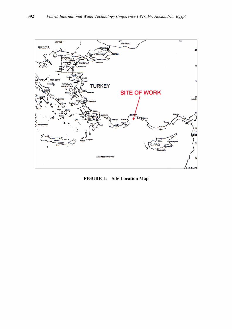
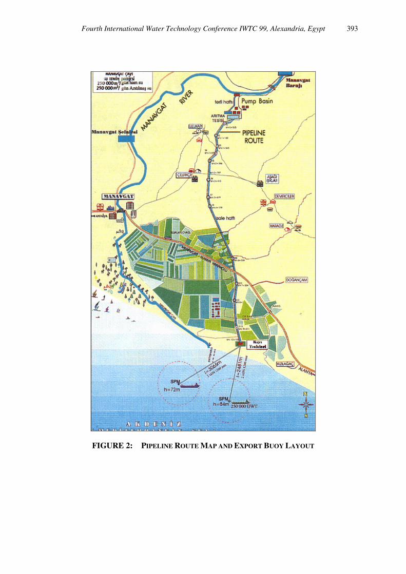
The Manavgat River is 82 kms long, has a catchment area of 1350 square kilometers and flows out to the Mediterranean at Kiyi Tesisleri, at the east of Antalya – Turkey. The site location map is shown in Figure 1. The quality of the water is very good and as it is located in an area that is not densely populated, which would need great quantities of water for urban or agricultural use, there is a naturally occurring surplus. Recognizing the present and growing future importance of water as a valuable commodity, the Manavgat River Water Supply Project has been developed to export fresh or drinking water to clients in the Mediterranean area and perhaps elsewhere. The water is taken from the river downstream of the Manavgat hydroelectric power plant, at approximately 10 kms inland. Here it enters a pumping station in order to gain enough hydraulic head to pass over the 67 meters land height on its direct route to the shore export facilities. The onshore constructed facilities consist of water treatment including aeration, flocculation, clarification, and filtering. Two 1600 mm diameter pipelines (one for fresh and one for treated water) take the water in a north south route of 10 kms to a shore manifold/valve station. From here it flows through subsea pipelines to the Loading Buoy facilities supplied by SBM. They are designated “East SPM” and “West SPM” (Single Point Mooring). Each SPM being served by two 48"(1200mm) diameter subsea pipelines which terminate in individual Pipeline End Manifolds (PLEM). The two loading SPMs are located respectively 2.5 and 3.0 kms offshore, in approximately 80 m of water depth.
Fourth International Water Technology Conference IWTC 99, Alexandria, Egypt 387
The Manavgat River Pipeline Route and Export Buoys Layout is shown in Figure 2.
3. SITE SURVEYS FOR OFFSHORE TERMINAL
In order to assess the seabed conditions at the anchoring area of the two SPM and PLEM positions, both geophysical and geotechnical surveys have been carried out.
3.1 GEOPHYSICAL SURVEY
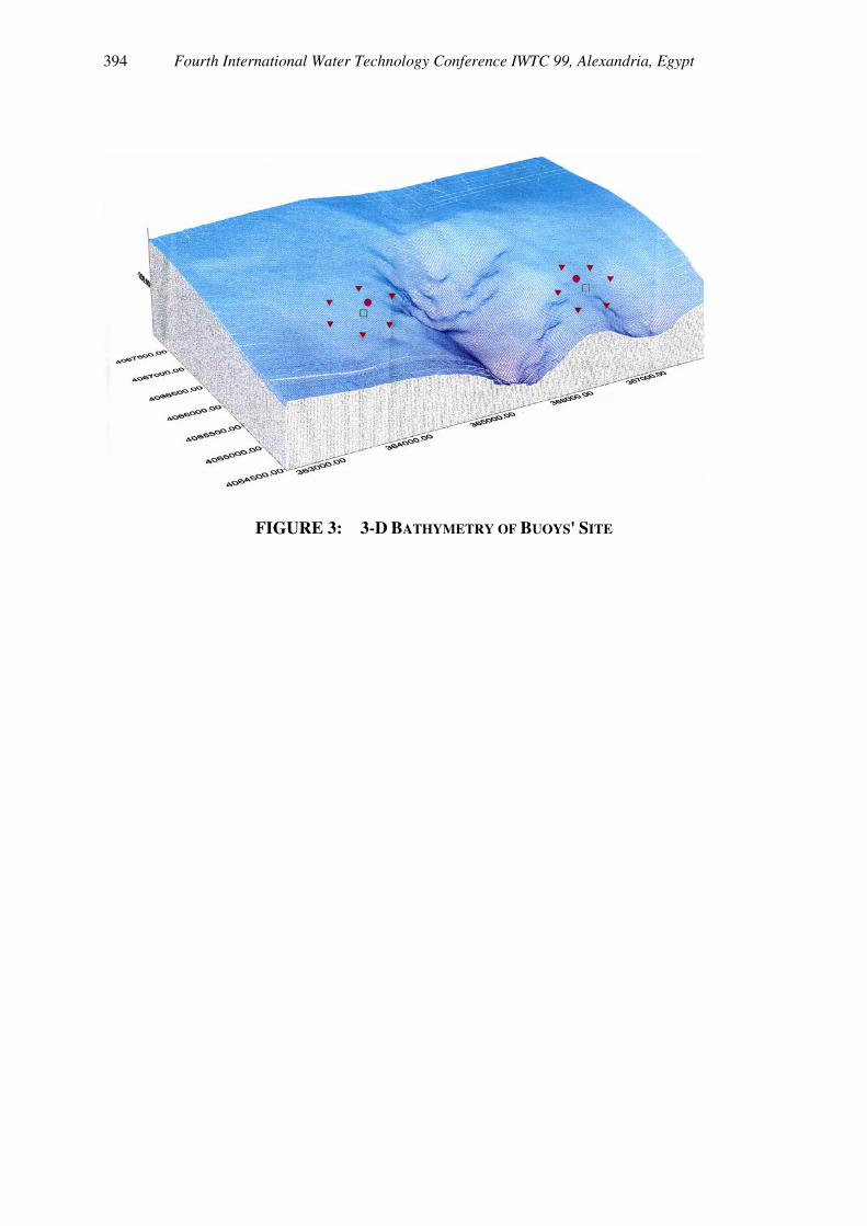
A pre-engineering site survey has been performed at the intended anchoring area of the SPMs making use of the following equipment: a) Echo-Sounder (Bathymetric data) b) Side-Scan Sonar (seabed features and obstructions) c) Sub-bottom profiler (shallow geology) d) Magnetometer (presence and position of potential obstructions: existing cables, wrecks, other pipelines and other hazards or obstructions). For each SPM site, a square area of 2100 x 2100 m has been covered by the survey. A total number of 14 drop cores (shallow soil samples) have also been carried out at the anchor point locations and PLEM positions to identify the nature of the superficial sediments. The main results of the bathymetric survey indicate the presence of important seabed slope ranging between 15 to 35%. The measured water depths of the SPM centres are between 78 and 85 m. However, the anchor points of the Buoys are located in water depths which vary from 55 to 130m. The 3-D Bathymetric chart of the site is shown in Figure 3. The seabed is mainly characterized by three types of materials: - From shore to 20 m water depth: sandy soils - From 20 m to deeper: very soft / soft "unconsolidated" sediment (clay-silt).
Fourth International Water Technology Conference IWTC 99, Alexandria, Egypt 388
- Eastern part: some rock outcrops probably due to fault plane of the morphology.
3.2 GEOTECHNICAL INVESTIGATION
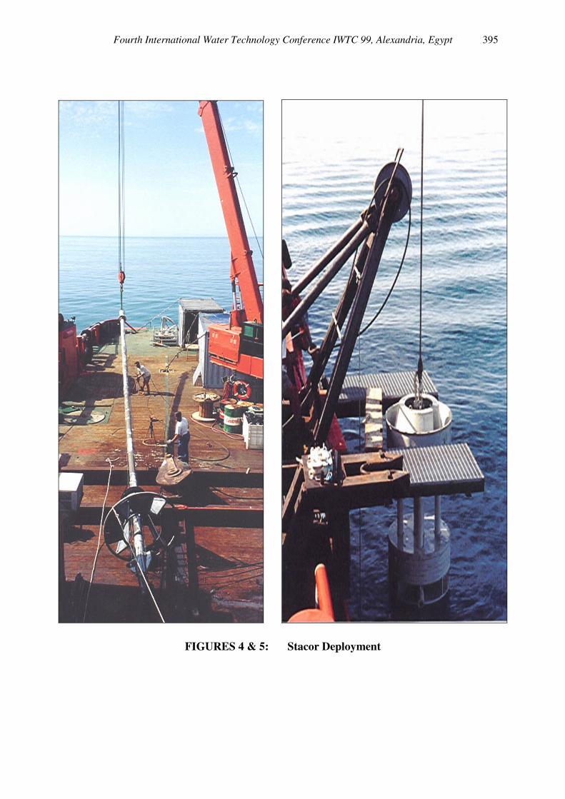
In addition to the geophysical survey, a geotechnical investigation has also been carried out to assess the soil conditions and design parameters for the design of the anchor points of the two Buoys and of the PLEM foundations. An innovative stationary piston core (STACOR) has been deployed by GEOCEAN SOLMARINE to collect very high quality samples up to 15 m below mudline, at each anchor point location of the SPMs. A complete soil laboratory testing program has then been performed on the gathered samples to derive the soil shear strength parameters and therefore to allow an appropriate sizing of the anchor points. The STACOR has been deployed on site using a conventional supply boat, thus reducing operation cost (cf. Figures 4 and 5).
4. LOADING BUOY DESIGN DATA AND CHARACTERISTICS
The SPMs have been designed to accommodate the maximum loading force of a water tanker of the size of 250.000 DWT. The environmental design conditions are summarized below:
Fourth International Water Technology Conference IWTC 99, Alexandria, Egypt 389
4.1 SURVIVAL CONDITIONS
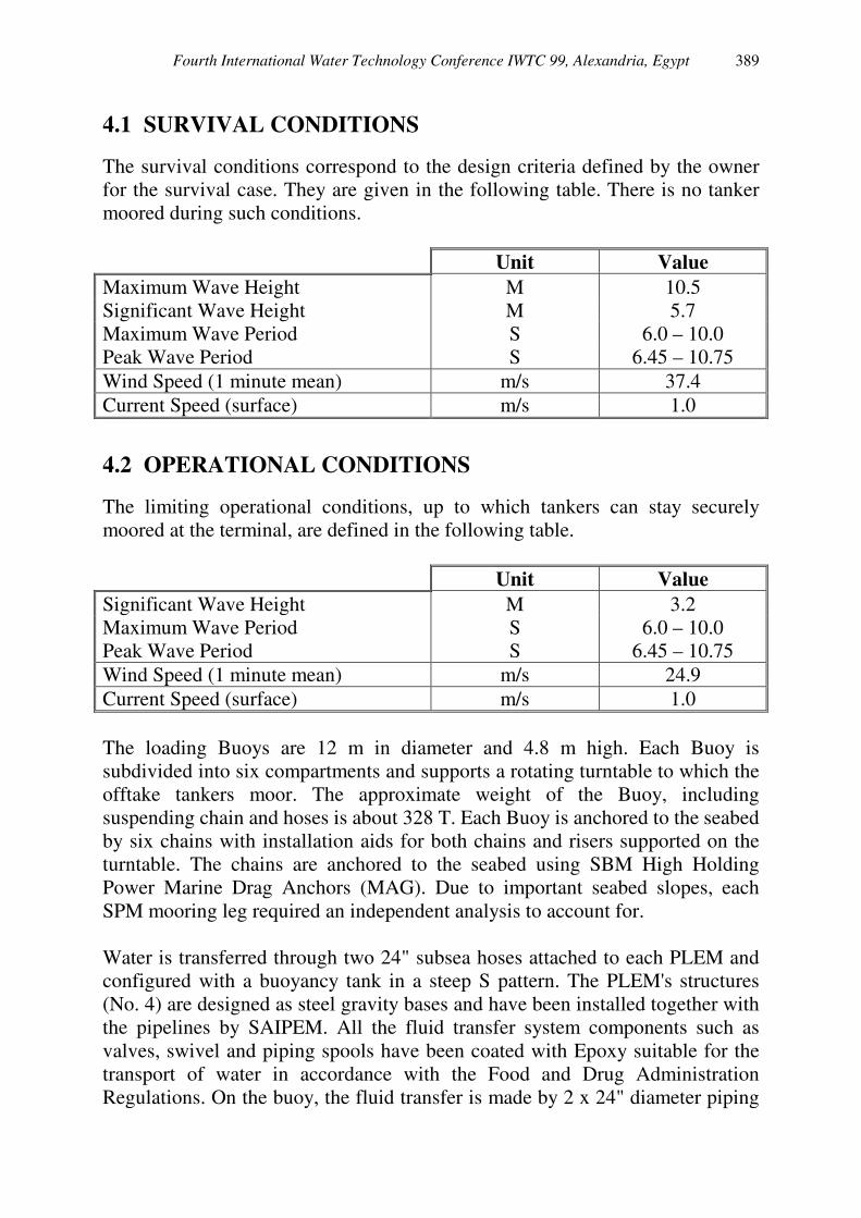
The survival conditions correspond to the design criteria defined by the owner for the survival case. They are given in the following table. There is no tanker moored during such conditions.
Unit Value Maximum Wave Height M 10.5 Significant Wave Height M 5.7 Maximum Wave Period S 6.0 – 10.0 Peak Wave Period S 6.45 – 10.75 Wind Speed (1 minute mean) m/s 37.4 Current Speed (surface) m/s 1.0
4.2 OPERATIONAL CONDITIONS
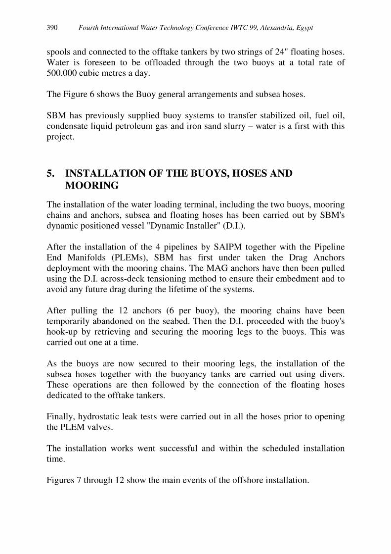
The limiting operational conditions, up to which tankers can stay securely moored at the terminal, are defined in the following table.
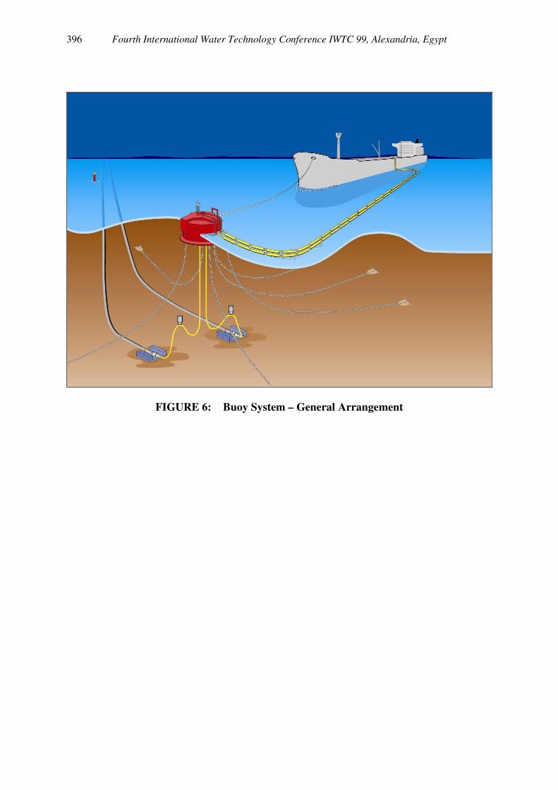
Unit Value Significant Wave Height M 3.2 Maximum Wave Period S 6.0 – 10.0 Peak Wave Period S 6.45 – 10.75 Wind Speed (1 minute mean) m/s 24.9 Current Speed (surface) m/s 1.0 The loading Buoys are 12 m in diameter and 4.8 m high. Each Buoy is subdivided into six compartments and supports a rotating turntable to which the offtake tankers moor. The approximate weight of the Buoy, including suspending chain and hoses is about 328 T. Each Buoy is anchored to the seabed by six chains with installation aids for both chains and risers supported on the turntable. The chains are anchored to the seabed using SBM High Holding Power Marine Drag Anchors (MAG). Due to important seabed slopes, each SPM mooring leg required an independent analysis to account for. Water is transferred through two 24" subsea hoses attached to each PLEM and configured with a buoyancy tank in a steep S pattern. The PLEM's structures (No. 4) are designed as steel gravity bases and have been installed together with the pipelines by SAIPEM. All the fluid transfer system components such as valves, swivel and piping spools have been coated with Epoxy suitable for the transport of water in accordance with the Food and Drug Administration Regulations. On the buoy, the fluid transfer is made by 2 x 24" diameter piping
Fourth International Water Technology Conference IWTC 99, Alexandria, Egypt 390
spools and connected to the offtake tankers by two strings of 24" floating hoses. Water is foreseen to be offloaded through the two buoys at a total rate of 500.000 cubic metres a day. The Figure 6 shows the Buoy general arrangements and subsea hoses. SBM has previously supplied buoy systems to transfer stabilized oil, fuel oil, condensate liquid petroleum gas and iron sand slurry – water is a first with this project.
5. INSTALLATION OF THE BUOYS, HOSES AND MOORING
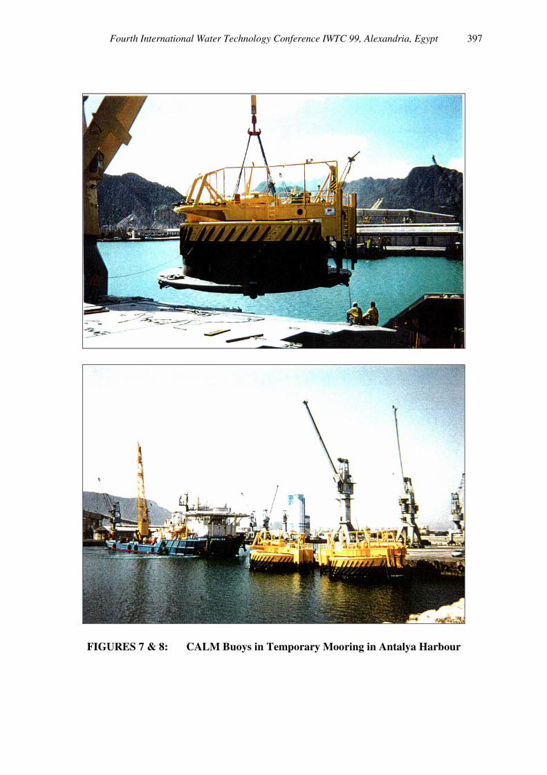
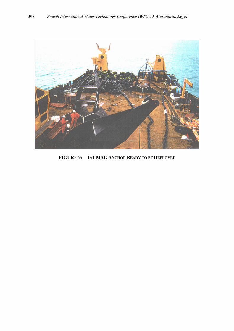
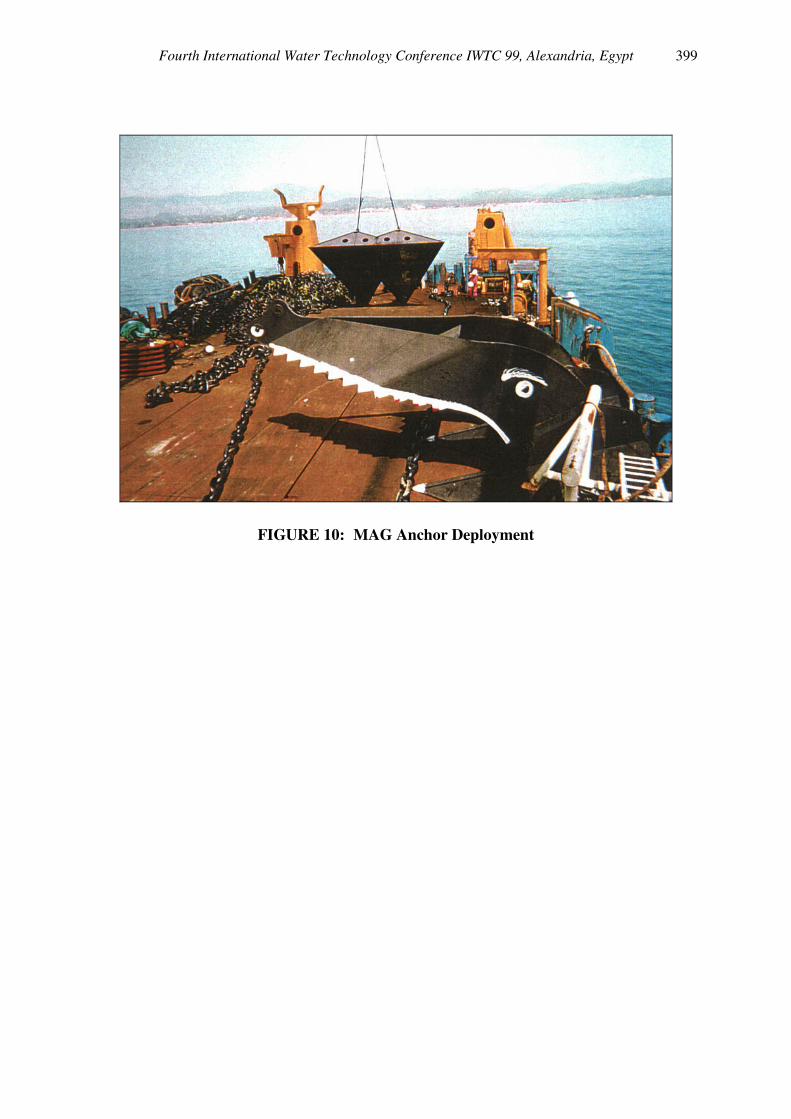
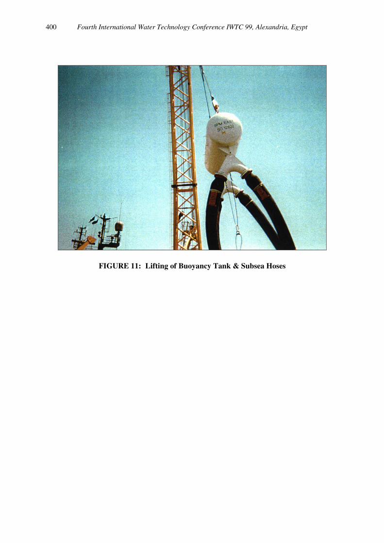
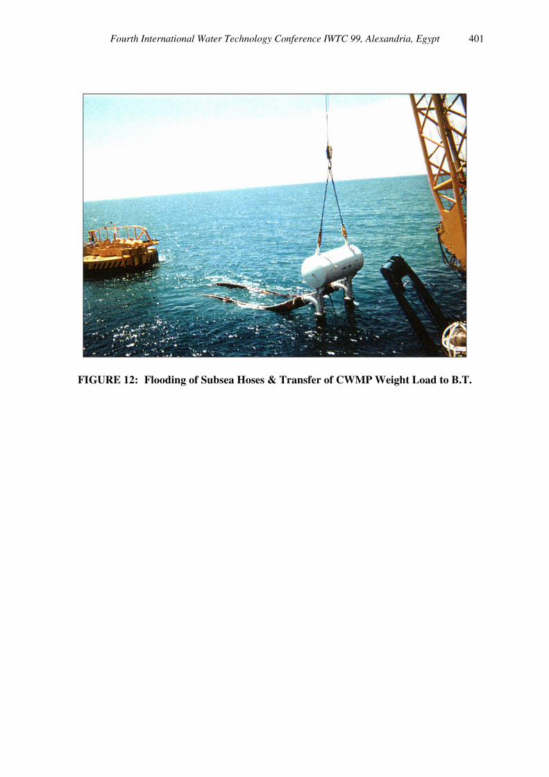
The installation of the water loading terminal, including the two buoys, mooring chains and anchors, subsea and floating hoses has been carried out by SBM's dynamic positioned vessel "Dynamic Installer" (D.I.). After the installation of the 4 pipelines by SAIPM together with the Pipeline End Manifolds (PLEMs), SBM has first under taken the Drag Anchors deployment with the mooring chains. The MAG anchors have then been pulled using the D.I. across-deck tensioning method to ensure their embedment and to avoid any future drag during the lifetime of the systems. After pulling the 12 anchors (6 per buoy), the mooring chains have been temporarily abandoned on the seabed. Then the D.I. proceeded with the buoy's hook-up by retrieving and securing the mooring legs to the buoys. This was carried out one at a time. As the buoys are now secured to their mooring legs, the installation of the subsea hoses together with the buoyancy tanks are carried out using divers. These operations are then followed by the connection of the floating hoses dedicated to the offtake tankers. Finally, hydrostatic leak tests were carried out in all the hoses prior to opening the PLEM valves. The installation works went successful and within the scheduled installation time. Figures 7 through 12 show the main events of the offshore installation.
Fourth International Water Technology Conference IWTC 99, Alexandria, Egypt 391
6. CONCLUSIONS AND FUTURE DEVELOPMENTS IN WATER LOADING AND OFFLOADING BUOYS
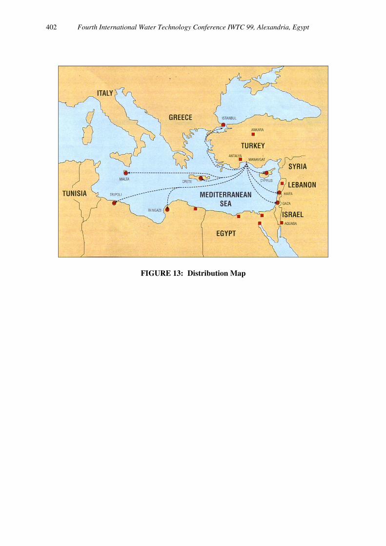
Recognizing the present and growing future importance of water as a valuable commodity, the Manavgat River Water Supply Project has been developed to export fresh or drinking water to Clients in the Mediterranean area and perhaps elsewhere. The use of Loading Buoys to export water (instead of usually oil), is to our knowledge the first project of this type and has proven to be very suitable. The Buoy's fluid transfer system has been modified in order to be suitable for drinking water. This means that we applied here a system, which is very reliable and has proven itself by being used for the past 40 years. Although difficult site conditions have been identified, the design and installation of the Buoys, including their anchoring systems have been executed successfully. In comparison to pipelines, we can state that the application of loading and offloading water, by making use of CALM-Buoy Terminal Systems, has proven to be the most economical solution. The potential buyers for this water may be from the tourist areas around Manavgat, Northern Cyprus, the nearby Greek islands, Israel, Libya and other Arabic countries. Dedicated vessels are now foreseen to serve customers (cf. Figure 13). Water in essential for all life and since the Earth's water is limited in quantity and quality; it became an important commodity, vulnerable to pollution. The controlled production, correct treatment and transportation of water to those countries where it is scarce will provide a product that is vital for economical and social developments.
Fourth International Water Technology Conference IWTC 99, Alexandria, Egypt 392
FIGURE 1: Site Location Map
Fourth International Water Technology Conference IWTC 99, Alexandria, Egypt 393
FIGURE 2: PIPELINE ROUTE MAP AND EXPORT BUOY LAYOUT
Fourth International Water Technology Conference IWTC 99, Alexandria, Egypt 394
FIGURE 3: 3-D BATHYMETRY OF BUOYS' SITE
Fourth International Water Technology Conference IWTC 99, Alexandria, Egypt 395
FIGURES 4 & 5: Stacor Deployment
Fourth International Water Technology Conference IWTC 99, Alexandria, Egypt 396
FIGURE 6: Buoy System – General Arrangement
Fourth International Water Technology Conference IWTC 99, Alexandria, Egypt 397
FIGURES 7 & 8: CALM Buoys in Temporary Mooring in Antalya Harbour
Fourth International Water Technology Conference IWTC 99, Alexandria, Egypt 398
FIGURE 9: 15T MAG ANCHOR READY TO BE DEPLOYED
Fourth International Water Technology Conference IWTC 99, Alexandria, Egypt 399
FIGURE 10: MAG Anchor Deployment
Fourth International Water Technology Conference IWTC 99, Alexandria, Egypt 400
FIGURE 11: Lifting of Buoyancy Tank & Subsea Hoses
Fourth International Water Technology Conference IWTC 99, Alexandria, Egypt 401
FIGURE 12: Flooding of Subsea Hoses & Transfer of CWMP Weight Load to B.T.
Fourth International Water Technology Conference IWTC 99, Alexandria, Egypt 402
FIGURE 13: Distribution Map