Embed Size (px)
DESCRIPTION
Networking
Citation preview

Local Area Network (LAN)
Editor by:
SigWa
Overview Now that you have a basic understanding of the OSI model and
what happens to data packets as they travel through the layers, it is time for you to start looking at basic networking devices. By working through the layers of the OSI reference model, you will learn what devices operate at each layer as data packets travel through them from the source to the destination.
In this chapter, you will learn about basic LAN devices and the evolution of networking devices. You will also learn about the networking devices that operate at each layer of the OSI model and how packets flow through each device as they go through the layers of the OSI model.
The teaching topology Topology defines the structure of the
network. There are two parts to the topology definition:
the physical topology, which is the actual layout of the wire (media), and the logical topology, which defines how the media is accessed by the hosts.
The physical topologies that are commonly used are the Bus, Ring, Star, Extended Star, Hierarchical, and Mesh.
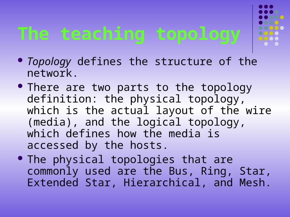
Physical Topologies
Physical Topologies (cont.) A bus topology uses a single backbone segment (length of cable) that all
the hosts connect to directly. A ring topology connects one host to the next and the last host to the
first. This creates a physical ring of cable. A star topology connects all cables to a central point of concentration.
This point is usually a hub or switch, which will be described later in the chapter.
An extended star topology uses the star topology to be created. It links individual stars together by linking the hubs/switches. This, as you will learn later in the chapter, will extend the length and size of the network.
A hierarchical topology is created similar to an extended star but instead of linking the hubs/switches together, the system is linked to a computer that controls the traffic on the topology.
A mesh topology is used when there can be absolutely no break in communications, for example the control systems of a nuclear power plant. So as you can see in the graphic, each host has its own connections to all other hosts. This also reflects the design of the Internet, which has multiple paths to any one location.
LAN devices in a topology Devices that connect directly to a network segment
are referred to as hosts. These hosts include computers, both clients and servers, printers, scanners, and many other user devices.
These devices provide the users with connection to the network, with which the users share, create, and obtain information.
The host devices can exist without a network, but without the network we have greatly limited the hosts capabilities.
LAN devices in a topology (cont.) Host devices are not part of any layer. They have a physical
connection to the network media by having a network interface card (NIC) and the other OSI layers are performed in software inside the host. This means that they operate at all 7 layers of the OSI model. They perform the entire process of encapsulation and decapsulation to do their job of sending e-mails, printing reports, scanning pictures, or accessing databases.
There are not standardized symbols within the networking industry for hosts, but they are usually fairly obvious to figure out. They bear a resemblance to the real device so that you are constantly reminded of that device.
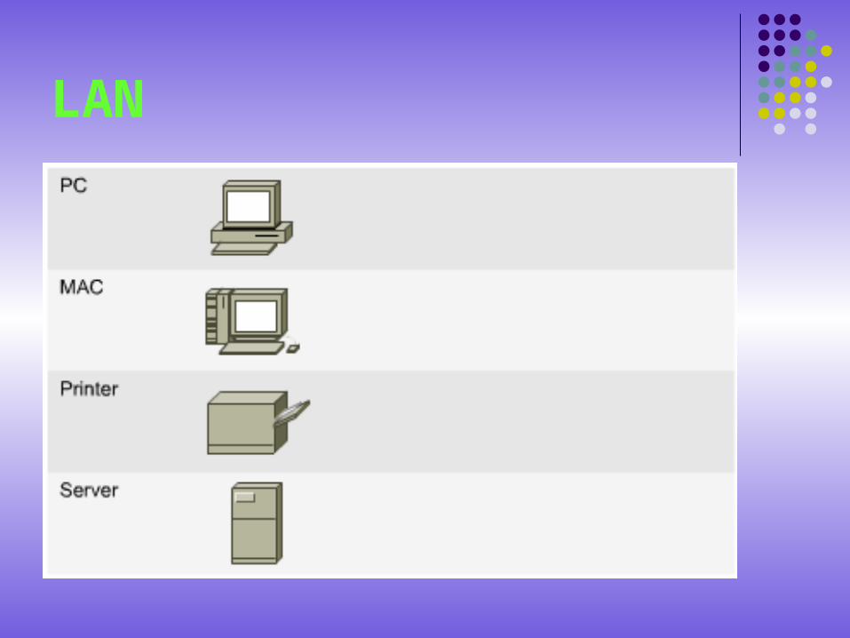
LAN
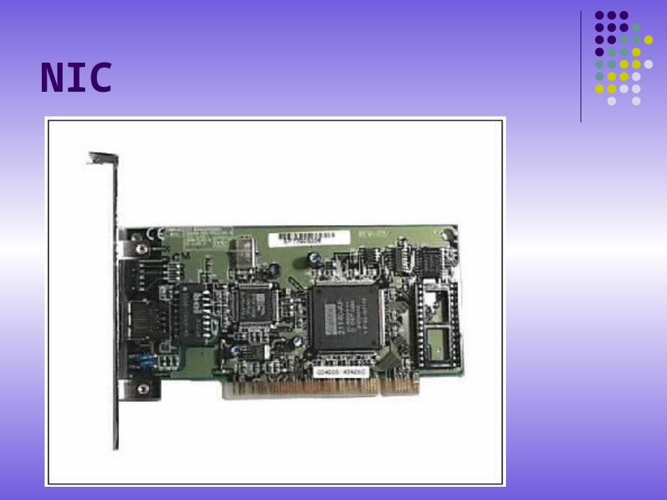
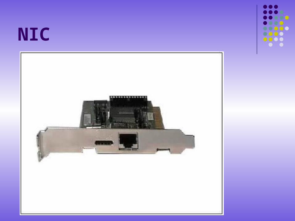
NIC NICs are considered Layer 2 devices because each
individual NIC throughout the world carries a unique code, called a Media Access Control (MAC) address. This address is used to control data communication for the host on the network.
NICs have no standardized symbol. It is implied that whenever you see networking devices attached to network media, there is some sort of NIC or NIC-like device present even though it is generally not shown. Wherever you see a dot on a topology, there is either a NIC or an interface (port), which acts like at least part of a NIC.
NIC
NIC

NIC: Layer 2 Device
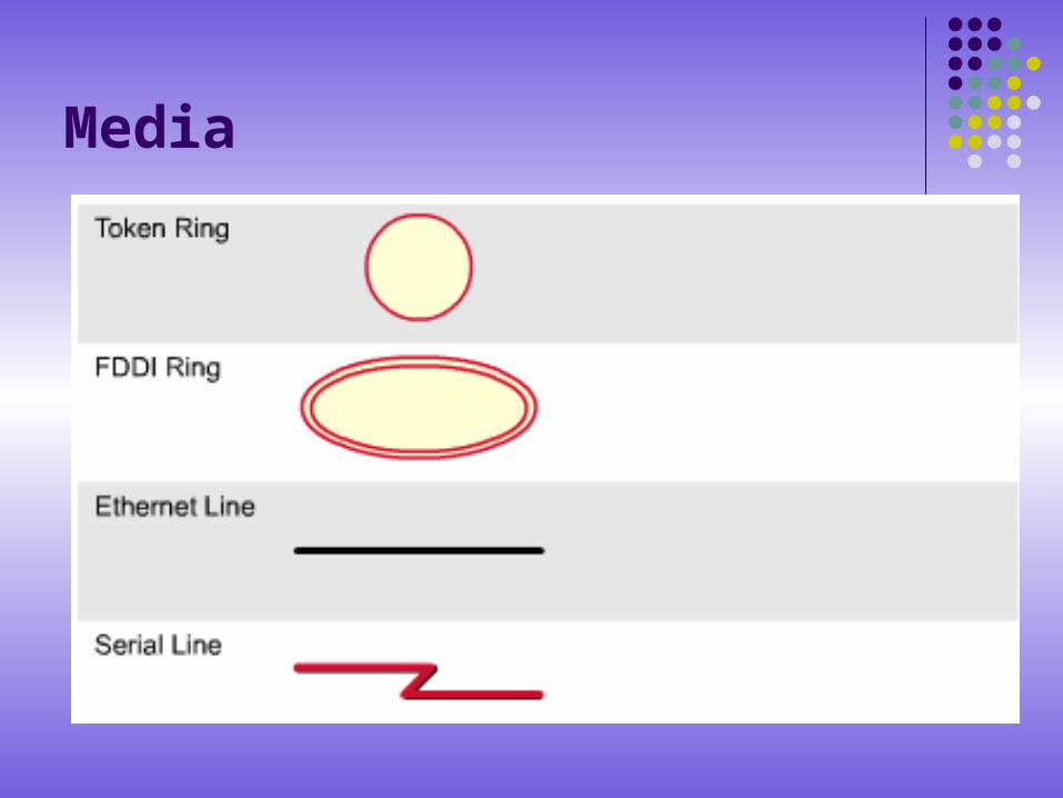
Media The symbols for media vary. For example: the Ethernet symbol is
typically a straight line with perpendicular lines projecting from it; the token-ring network symbol is a circle with hosts attached to it; and for FDDI, the symbol is two concentric circles with attached devices.
The basic functions of media are to carry a flow of information, in the form of bits and bytes, through a LAN. Other than wireless LANs (that use the atmosphere, or space, as the medium) and the new PANs (personal area networks, that use the human body as a networking medium!), networking media confine network signals to a wire, cable, or fiber. Networking media are considered Layer 1 components of LANs.
Media
Repeaters
One of the disadvantages of the type of cable that we primarily use (CAT5 UTP) is cable length.
The maximum length for UTP cable in a network is 100 meters (approximately 333 feet).
If we need to extend our network beyond that limit, we must add a device to our network. This device is called a repeater.
Repeaters (cont.) The purpose of a repeater is regenerate and retime
network signals at the bit level to allow them to travel a longer distance on the media.
Watch out for the Four Repeater Rule for 10Mbps Ethernet, also know as the 5-4-3 Rule, when extending LAN segments. This rule states that you can connect five network segments end-to-end using four repeaters but only three segments can have hosts (computers) on them.
Repeater
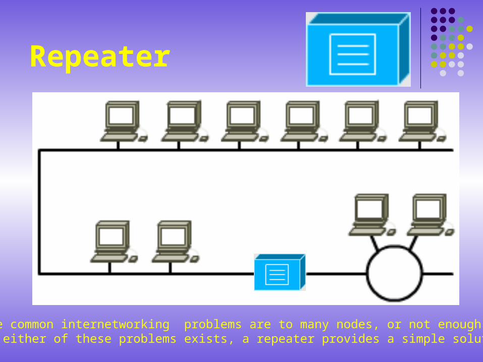
The common internetworking problems are to many nodes, or not enough cables.If either of these problems exists, a repeater provides a simple solution.
Repeaters (cont.)
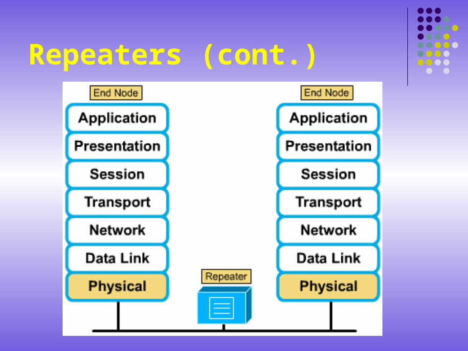
The term repeater traditionally meant a single port "in" and a single port "out" device. But in common terminology today the term multiport repeater is often used as well. Repeaters are classified as Layer 1 devices in the OSI model, because they act only on the bit level and look at no other information.
Repeaters (cont.)
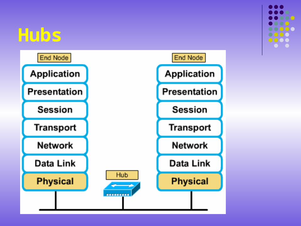
Hubs The purpose of a hub is to regenerate and retime network
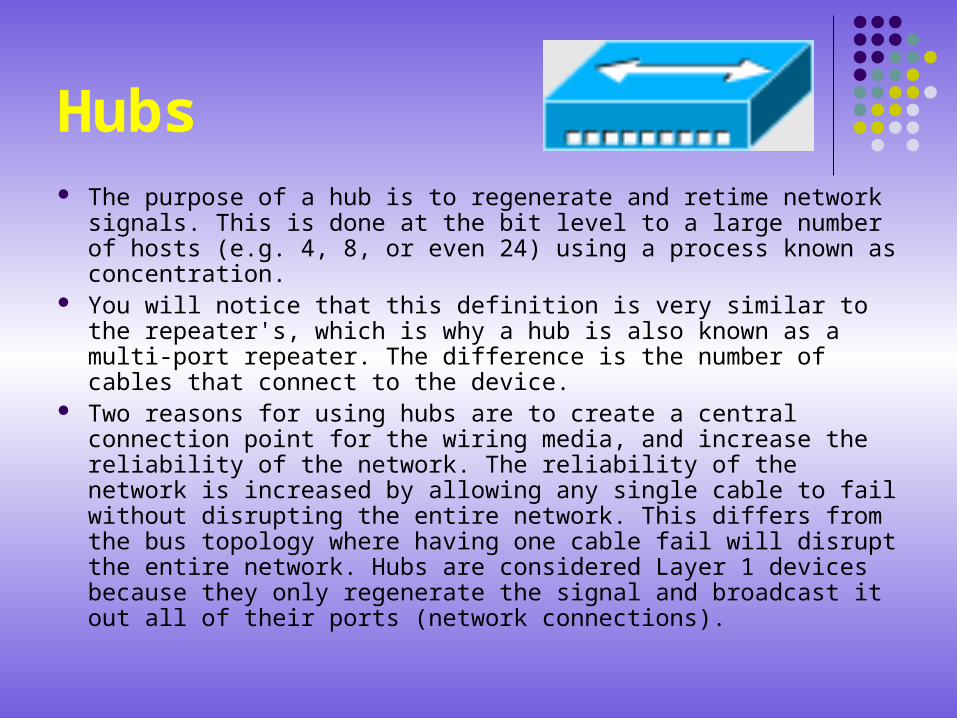
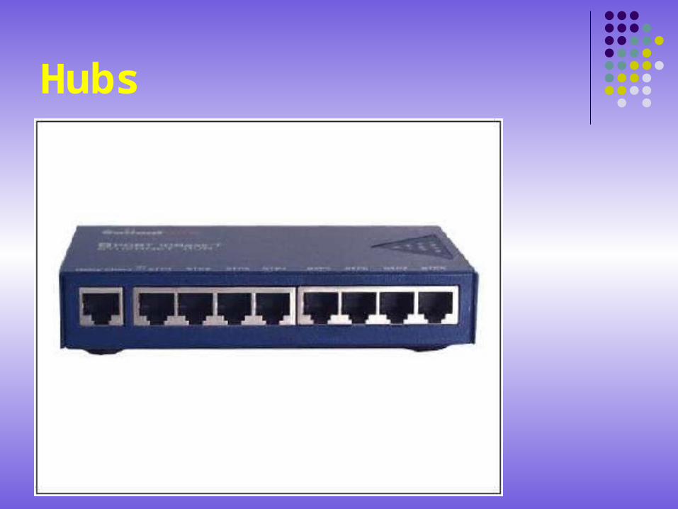
signals. This is done at the bit level to a large number of hosts (e.g. 4, 8, or even 24) using a process known as concentration.
You will notice that this definition is very similar to the repeater's, which is why a hub is also known as a multi-port repeater. The difference is the number of cables that connect to the device.
Two reasons for using hubs are to create a central connection point for the wiring media, and increase the reliability of the network. The reliability of the network is increased by allowing any single cable to fail without disrupting the entire network. This differs from the bus topology where having one cable fail will disrupt the entire network. Hubs are considered Layer 1 devices because they only regenerate the signal and broadcast it out all of their ports (network connections).
Hubs
Hubs
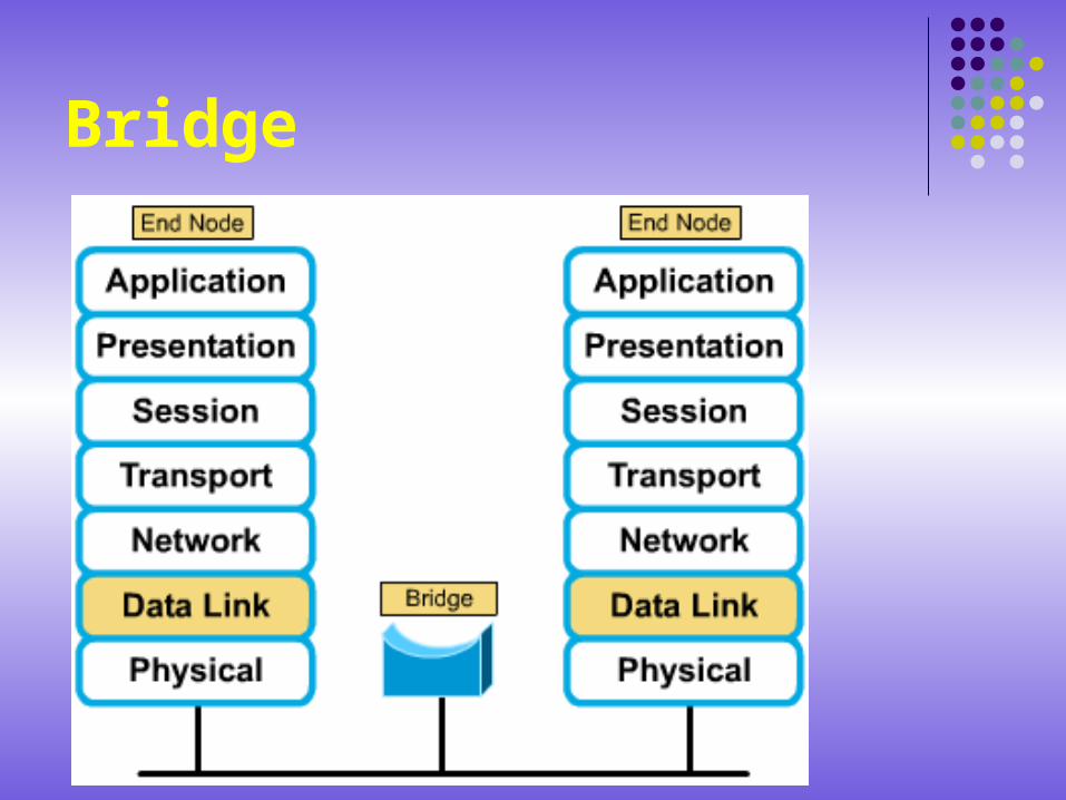
Bridges A bridge is a Layer 2 device designed to connect two LAN
segments. The purpose of a bridge is to filter traffic on a LAN, to keep local traffic local, yet allow connectivity to other parts (segments) of the LAN for traffic that has been directed there.
You may wonder, then, how the bridge knows which traffic is local and which is not. The answer is the same one that the postal service uses when asked how it knows which mail is local. It looks at the local address. Every networking device has a unique MAC address on the NIC, the bridge keeps track of which MAC addresses are on each side of the bridge and makes its decisions based on this MAC address list.
Bridge
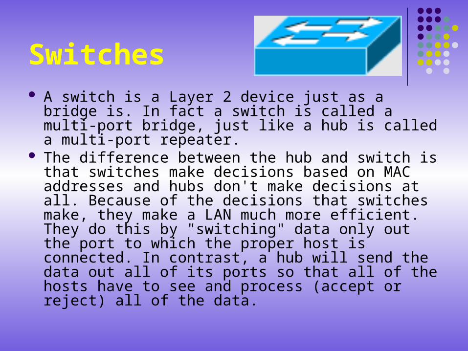
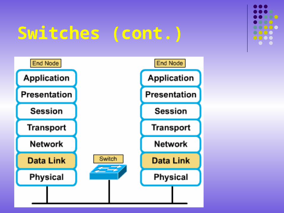
Switches A switch is a Layer 2 device just as a bridge is. In
fact a switch is called a multi-port bridge, just like a hub is called a multi-port repeater.
The difference between the hub and switch is that switches make decisions based on MAC addresses and hubs don't make decisions at all. Because of the decisions that switches make, they make a LAN much more efficient. They do this by "switching" data only out the port to which the proper host is connected. In contrast, a hub will send the data out all of its ports so that all of the hosts have to see and process (accept or reject) all of the data.
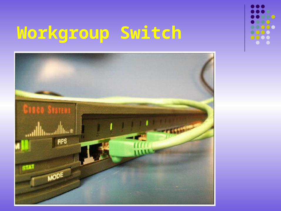
Workgroup Switch
Switches (cont.) Switches at first glance often look like hubs. Both
hubs and switches have many connection ports, since part of their function is connectivity concentration (allowing many devices to be connected to one point in the network). The difference between a hub and a switch is what happens inside the device.
The purpose of a switch is to concentrate connectivity, while making data transmission more efficient. For now, think of the switch as something that is able to combine the connectivity of a hub with the traffic regulation of a bridge on each port.
Switches (cont.)
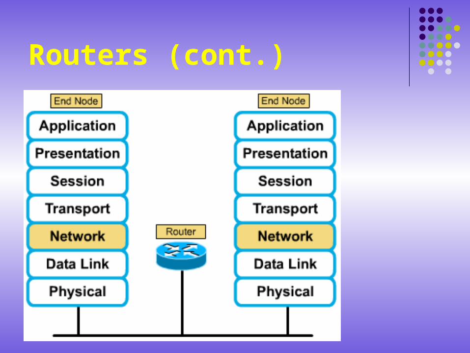
Routers The router is the first device that you will work with
that is at the OSI network layer, or otherwise known as Layer 3.
Working at Layer 3 allows the router to make decisions based on groups of network addresses (Classes) as opposed to individual Layer 2 MAC addresses.
Routers can also connect different Layer 2 technologies, such as Ethernet, Token-ring, and FDDI. However, because of their ability to route packets based on Layer 3 information, routers have become the backbone of the Internet, running the IP protocol.
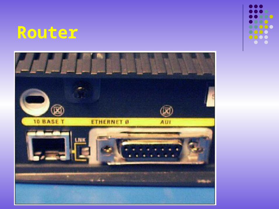
Router
Routers The purpose of a router is to examine incoming
packets (Layer 3 data), choose the best path for them through the network, and then switch them to the proper outgoing port.
Routers are the most important traffic-regulating devices on large networks.
They enable virtually any type of computer to communicate with any other computer anywhere in the world! While performing these basic functions, routers can also execute many other tasks.
Routers (cont.)
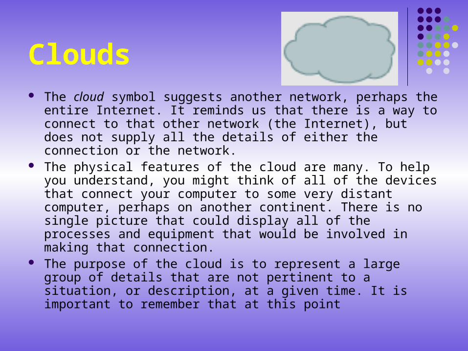
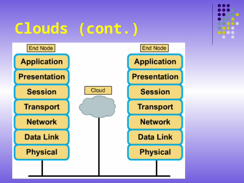
Clouds The cloud symbol suggests another network, perhaps the entire
Internet. It reminds us that there is a way to connect to that other network (the Internet), but does not supply all the details of either the connection or the network.
The physical features of the cloud are many. To help you understand, you might think of all of the devices that connect your computer to some very distant computer, perhaps on another continent. There is no single picture that could display all of the processes and equipment that would be involved in making that connection.
The purpose of the cloud is to represent a large group of details that are not pertinent to a situation, or description, at a given time. It is important to remember that at this point
Clouds (cont.)
Evolution of networking devices and the OSI layers
Hosts and servers operate at Layers 2-7; they perform the encapsulation process. Transceivers, repeaters, and hubs are all considered active Layer 1 devices, because they act only on bits and require energy. Patch cables, patch panels, and other interconnection components are considered passive Layer 1 components because they simply provide some sort of conducting path.
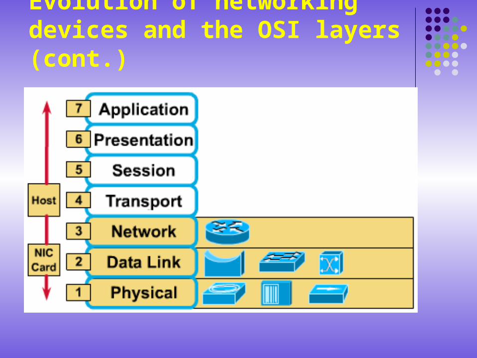
Evolution of networking devices and the OSI layers (cont.)
NICs are considered Layer 2 devices since they are the location of the MAC address; but since they often handle signaling and encoding they are also Layer 1 devices. Bridges and switches are considered Layer 2 devices because they use Layer 2 (MAC address) information to make decision on whether or not to forward packets. They also operate on Layer 1 in order to allow bits to interact with the media.
Evolution of networking devices and the OSI layers (cont.)
Routers are considered Layer 3 devices because they use Layer 3 (network) addresses to choose best paths and to switch packets to the proper route. Router interfaces operate at Layers 2 and 1 as well as Layer 3. Clouds, which may include routers, switches, servers, and many devices we have not yet introduced, involve Layers 1-7.
Evolution of networking devices and the OSI layers (cont.)