Embed Size (px)
Citation preview

I TRIDEN SERIESOPERATING TECHNIQUES
I
IIn the pages that fellew, we have included techniques fer:
VOR NavigatienVOR ApproachesLocalizer ApproachesGlides/ope Arming & CouplingLocalizer Back CourseI
INOTEThe TRIDEN SERIES autopilot is capable of tracking lateral information from a toraner GPS. Severalfactors in procedure and operation are important to. remember. Adjust the course wiejo' C sensitivity) ofthe loran or GPS to. insure it is net tee wide or tee narrow (represented as nautical 'ies per dot). Onmost IFR Approach Certified GPS's this is done autematically. A course width toe v-nde WfJ· ,dcause theautopilot to. S-turn back and ferth aleng the desired track. Tee narrow would cause the autopiiotto beoverly sensitive to. COt movement, When tracking to. a desired waypeint, the bearing information l,vill bedisplayed on the loran or GPS. This bearing information must be input into. the autopilot thrcugheaner theheading bug (when using a DG) or the course arrow (when using an HSt) in order fer the autoplotto trackproperly.The photographs depict the Century Flight Systems Navigatienal Situatien Display 1000 (NSD 1000) asthe HSI and the standard Directienal Gyre. The techniques are equally applicable to. other compasssystems.
II
I
I
I
I
I
I
I~
I
I
I
IRev B 02'()5-03 14
-
I

15
Re" B 02-05-03

-=.
".'
. ,
III
III
IIII
III-
IIIII
STEP
HSI VOR Navigation
1
2
3
4
MODEHDG/NAVARM
ALT
NAVCPLSOFTALT
NAVCPUHDGALT
NAV CPL or ARMALT
Rev B 02-05-03
REMARKSA selected angle intercept ofup to 90" may be selected bysetting the course arrow to thedesired ratfiaJami the hearll11gbug to the appropriate hearlu.gfor the desi~sC mreroep_Momentarily press "',e NAVswitch on the a~i'nct. 1:-;;system Vim remaIn~.g tizheading bug untl ti:-e ~;'l
course turn.
After intercept, the s;~'T! Vdlcorrect for crosswind cmdadjust its internal radk~authority and limit bank a:-.gles
If a course change is requiredat the VOR, reposition thecourse arrow. If deviationsbecause of station passage isnot desired, press HOG andset the heading bug on thedesired course.
Station switching isaccomplished by tuning thenav receiver to the desiredstation and setting the coursewith the course arrow. Acourse change of 45 or morewill cause the system to kickout of "soft" mode and set up a45 intercept to the newcourse.
16
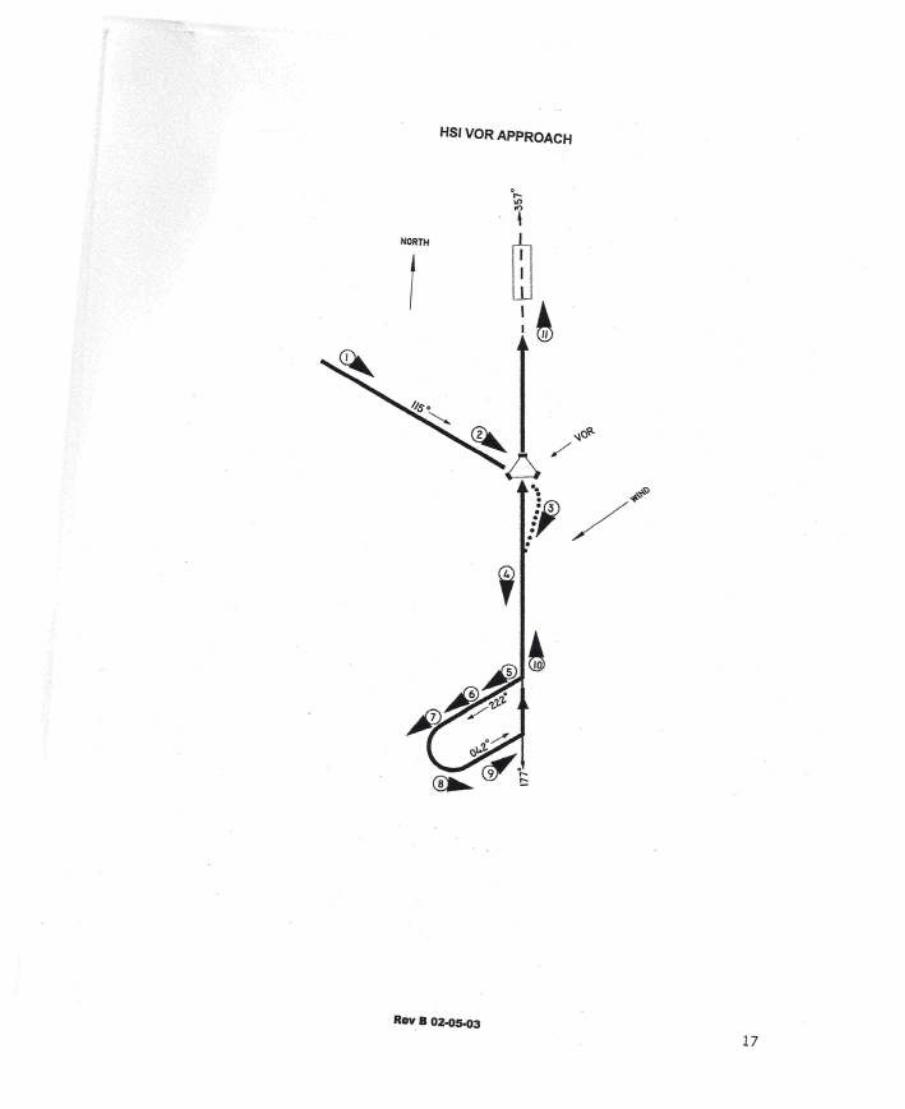
HSI VOR APPROACH
NORTH
I
Rev B 02-05-03
17


•
HSI VOR APPROACH
1
NORTH
Rev B 02.05-0319

II HSI VOR Approach
I STEP MOOE REMARKS5 HOG Turn the heading bug to the
ALTorATT outbound procedure tem
Iheading and p~-s the HOGswitch.
II 6 HOG Proceed outbound
ALT sufficient time has elapsed toassure proper re-interceptio .
II
7 .HOG Lead aircraft through the
ALT procedure turn by moving the
I heading bug in the direction ofthe procedural turn.
II 8 HOG/NAVARM As the aircraft continues to turn,
ALT momentarily press ·the NAVswitch and turn the heading bugto intercept the inbound course.
IIIIIII
Rev B 02-05-03 20
I

HSI VOR APPROACH
NORTH
I
•••;,••
Rev B 02.05.03
21
,,j
i;
I

IIIII
IIIIIIIIIIII
STEP
HSI VOR Approach
9
10
MODENAVCPL
ALT
NAVCPLSOFTATTorVS
REMARKS·As the aircraft approaches theinbound course, the system wit!switch out of the dual meda a~dturn to the inboundcezrse.
After the on course t',sm. mesystem will correct for cross•••:miand enter into a "soft" mode. Tm!aircraft's altitude and speedshould be controlled asappropriate for the approach.Once the aircraft has reachedminimums, disconnect theautopilot.
11 NAVCPLSOFTATT
Rev B 02-05-03
If a missed approach is required,disconnect the autopilot andestablish desired climb attitudeand airspeed. When appropriateselect HOG and ATT HOG andALT or HOG and and engageautopilot.
22

NOTES
Rev B 02-05-03 23

Ij
IIIIIIIIIIIIIIIII
NORTH
HSI LOCALIZER APPROACH
Rev B 02·05-03 24

STEP1
REMARKSille localizer or ILS approach:tEgins with a transition from theearoute structure to the outercompass locator (LOM).Momentarily press the REVswitch. The heading bug is usedto select the desired heading. Theaircraft's altitude may becontrolled by the modifier switch ormroughthe use of the mode. The{noound Front Course direction isselected with the course arrow.
2 3efore reaching the LOM, theautopilot will couple REV modeand track outbound.
3 Upon tracking the localizer, thes¢em will compensate fortrosswind and enter the "soft".-:nrAe. The procedure turn
u::Oound heading may now beselected with the heading bug.
4 e appropriate time, press the~:JG switch to begin the~7x.:edure turn. Altitude=?:hvpriate to this phase of theszeroach should be controlled:''50:''9.VS or ATT HLD as
-ECeSSary
Rev B 02·05·03 25
-I-j
=t

iiIIIIIIIIIIIIIIIII
NORTH
HSI LOCALIZER Approach
Rev B 02~05·03 26

STEP
HSI LOCAUZER Approach
5
6
7
8
MODEHOGALT
HOGALT
HOGALT
HOG/APRARMALTor ATT
Rev B 02-05-03
REMARKSProceed outbound in theprocedure turn until sufficient timehas elapsed to assure proper re-interception.
Lead the aircraft through theprocedure turn by moving theheading bug in the direction of theturn.
Continue to lead the aircraftthrough the turn.
Momentarily press the APRswitch. The HOG and APR ARMmessages should be displayed toindicate a dual mode. The aircraftwill follow the heading bug untilthe system determines when anon course turn is required.
27

rrrrr .rrrrrrrrr.IIIII
NORTH
I
HSI LOCALIZER Approach
Rev B 02·05·03 28

1I
STEP9
10
11
Rev B 02-05-03
APRCPLSOlGSARM
APRCPLSOFT
GSCAP
HDGATT
REMARKSWhen the on course turn isinitiated the HDG message willbe removedand the system willtrack the localizer. Afterintercept,the systemwill correctfor crosswindand enter into the"sott" mode. Internal radiogains and bank angles will belimited. The system will alsoautomatically arm for glideslope.
As the glide slope beam iscaptured, the ALT messageswill be removed. The systemwill track the localizer and glideslope. Power changes shouldbe performed in smallincrements as necessary tomaintain correct airspeed.Once the aircraft has reachedminimums, disconnect theauto ilot.If a missed approach isrequired, disconnect theautopilot and establish desiredclimb attitude and airspeed.When appropriate press HDGand ATT and engageautopilot.
1J
29

HSI GS ARMING & CAPTURE
I
t -
I
lIII
IIIII
\
\
\,\
\
\\
\
~t\
\
Rev B 02-05-03 30

STEP
AS' 'SSArming 8: Capture
1
2
3
4
5
ODE REMARKSI,APRCPLSOFT;; ALT. VS orfAn'~ GSARMIif
APRCPLSOFT
ALTorATTHLD
GSARM
APRCPLSOFT
GSCAP
APRCPLSOFT
GSCAP
HOGATT
Rev B 02·05·03
The typical glide slope portion ofan ILS begins with the aircraft inALT modes or in the AIT HLOmode with the aircraft on aclosure to the glide slope beam.
The TRIOEN SERIES autopilotsystem incorporates circuitry,which anticipates when captureshould occur. It is important theaircraft be configured for landingbefore ,the system capturesglideslope.
When capture occurs, the ALTVS or AIT messages will beremoved.The GS CAP message will bedisplayed indicating that theglideslope has captured.
Upon reaching the decisionheight, disconnect the autopilotand complete the approach orconduct normal missed approachprocedures as required.
If a missed approach is required,disengage the autopilot andfollow normal missed approachprocedures. . When appropriatepress the HOG and AIT switches'and engage autopilot. Set power'appropriately.
31

I NOTES
I,,,II,-IIIIIIII,
Rev B 02-05·03 32
I

HSI LocafizerBaekCoulSe
Rev B 02-05-03 33
I1
1I-.!-j
1
~1
Ii
Ij
I

IIIII
IIIIIIIIIIII
STEP
HSI Localizer Back Course
1
2
3
4
MODEHDG/NAVARMALTVS or ATT
NAVCPLSOFT
ALTVS or ATT
HDGALTVS orATT
HlD
HOGALTVS orATT
HLD
Rev B 02-05-03
REMARKSThe locanzer back courseapproach beginsv.'ffil a transitionfrom the enroute structure t·l)<mintercept with the bac'lt ccursaoutbound. The irblHi >on froritcourse is set on the =t:~ aJre,"'c. .Momentarily press ft'.e NAV s?'~"L
The system wIll ftillC'N ·.e .s ~bug until an on course t,;;, ;,smade,
As the outbound course is tm~,select the outbound procedure turnheading with the heading buy.Altitude should be centro Jed asappropriate for the procedure,
When the outbound procedure tumis desired, press the HDG switchand fly outbound for sufficient timeto permit re-interception.
Lead the aircraft 'through theprocedure turn by moving theheading bug in the direction of theturn.
34

NOF?TH
Rev 8 02-05.03
35
{,i'I
1

IIIIIIIIIIIIIIIIIII
HSI Localizer Back Course
STEP5
REMARKS
6
7
8
9
MODEHOG
ALTVSorATT
HOG/REV ARMALTVSorATT
REVCPLSOFT
ALTVS orATT
REVCPLSOFT
ATTorVS
HOGATT
Rev B 02-05-03
As the aircraft continues to turn,set the heading bug to theinboundprocedureturn heamn.:i.
Momentarily press the REVswitch. The HOG and Re-Vmessages should be dispfay-cdtoindicate the system is in a dualmode. The system will fonewtheheading bug until the on courseturn is initiated then the HOGmessageswill be removed.
After the on course turn iscompleted, the system will enterthe "soft" mode to limit radioauthority and bank angles and tocorrect for crosswind.
Control altitude and airspeed asappropriatefor the approach.
Once the aircraft has reachedminimums, disconnect theautopilot. If a missed approachisrequired, disconnect the autopilotand establish desired climbattitude and airspeed. Whenappropriate press HOG and AITand engageautopilot.
36

NOTES
Rev B 02-05-03 37

- ---,-- - - - -
w00
cG')
<o;uz~cO'~o;:,

OGVOR Navigation
Rev B 02·05-03
RemarksStep 1NAV ARM/ATT or ALT.A intercept to a selectedradial is accomplished byset- ting the OBS to thedesired radial and turningthe heading bug to thatsame degree and thenpressing the NAV switch onthe autopilot.Step 2NAV CPLIATT or ALT.After intercept, the autopilotwill correct for crosswindand adjust its internal radioauthority and limit bankangles.
Step 3NAV CPL/ATT or ALT.After station passage, theOBS indicates a FROMflag.If a course change isrequired at the VOR, turnthe aBS and heading bug tonew course. If a coursechange of more than isrequired, the autopilot willre-cycle for a standardinterce t.Step 4NAV CPLIATT or ALT.Station switching isaccomplished by tuning thereceiver to the new station.
Step 5HDG/ATT or ALT.For smooth station passage,it might be desirable tocycle the autopilot to theHOG mode before passage.Then after passage occursturn the OBS and headingbug to the new radial and
ress NAVon the auto ilot.
39

DG VOR APPROACH
NORTH
I
I
I
I
f
I
I
I
I
I
I
•
I
Rev B 02-05-03
40

OG VORApproach
Rev B 02-05-03
Step 3REV ARM/ATT or ALT.As the VOR is crossed, turnthe heading bug to theoutbound course and pressthe REV button.
I,
I
I
~
III
41 l
I
Step 1NAV CPUATT or ALT.The VOR approach usuallybegins from an enroutesituation. The heading bugand the OBS are set to thesame degree radial. Theautopilot is providingcrosswind correction to trackthe desired radial.
Step 2HOG/A TT or ALT.As the VOR is neared, matchthe heading bug to either thecourse or the lubber line andpress HOG on the autopilot.Set the OBS to the inboundcourse. Control altitude asnecessary for the procedure.
Step 4. REV CPUATT orALT.The autopilot will trackoutbound and correct forwind. Control attitude withthe modifier switches. Whenthe desired altitude isreached press ALT.
StepSHOG/ALT.To start the procedure turn,press HDG and turn theheading bug to the outboundprocedure turn heading.

II DG VOR Approach
I .I-\J')
1
I NORTH ill1I
. \
. \ ~I II
IIII i,/.~
•
I~
IIIIIIII
Rev B 02·05·03 42
I

OS VOR A.pproach
Rev B 02·05·03
Step 6HOG/A TT VS or ALT.Proceed outbound untilsufficient time as elapsedbefore starting the turninbound.
Step 7HOG/ALT.Lead the aircraft through theprocedure turn by movingthe heading bug ..
Step 8HOG/ALT.As the aircraft turns, movethe heading bug to thedesired heading to interceptthe inbound course.
Step 9NAV ARM/ALT.Press the NAV button andturn the heading bug to theinbound course (same asthe OBS). The autopilot willset up a 45° intercept angle.
Step 10NAV CPUATTVS or ALT.The autopilot will anticipatethe on course turn. Afterintercept it will correct forcrosswind, limit bank anglesand adjust it's radio gain.Control pitch as necessaryfor the approach. .
Step 11HOG/ATT.Once the aircraft hasreached the decision height,disconnect the autopilot andcontinue the approach orconduct the missedapproach. For the missedapproach, establish theaircraft's attitude andairspeed then turn theheading bug to the missedapproach heading. Re-engage the autopilot andmonitor aircraft'senvironment.
43

INOTES
IIIIIIIIIIIIIIIII
Rev B 02·05·03 44
I
OGLo cafizerA pproach
Revs 02-05-03
45

IDG Localizer Approach
IIIIIIIIIIIIIIIII
Rev B 02-05-03
I
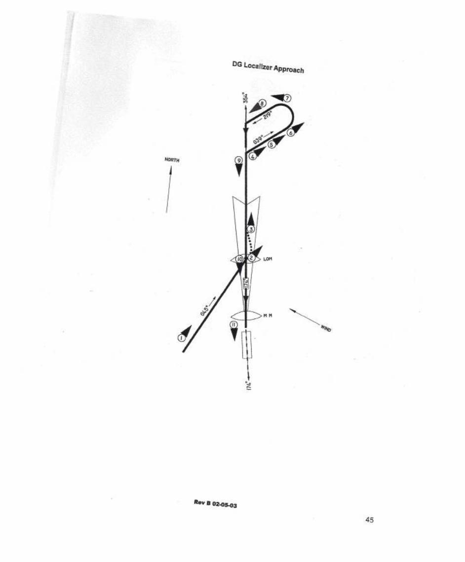
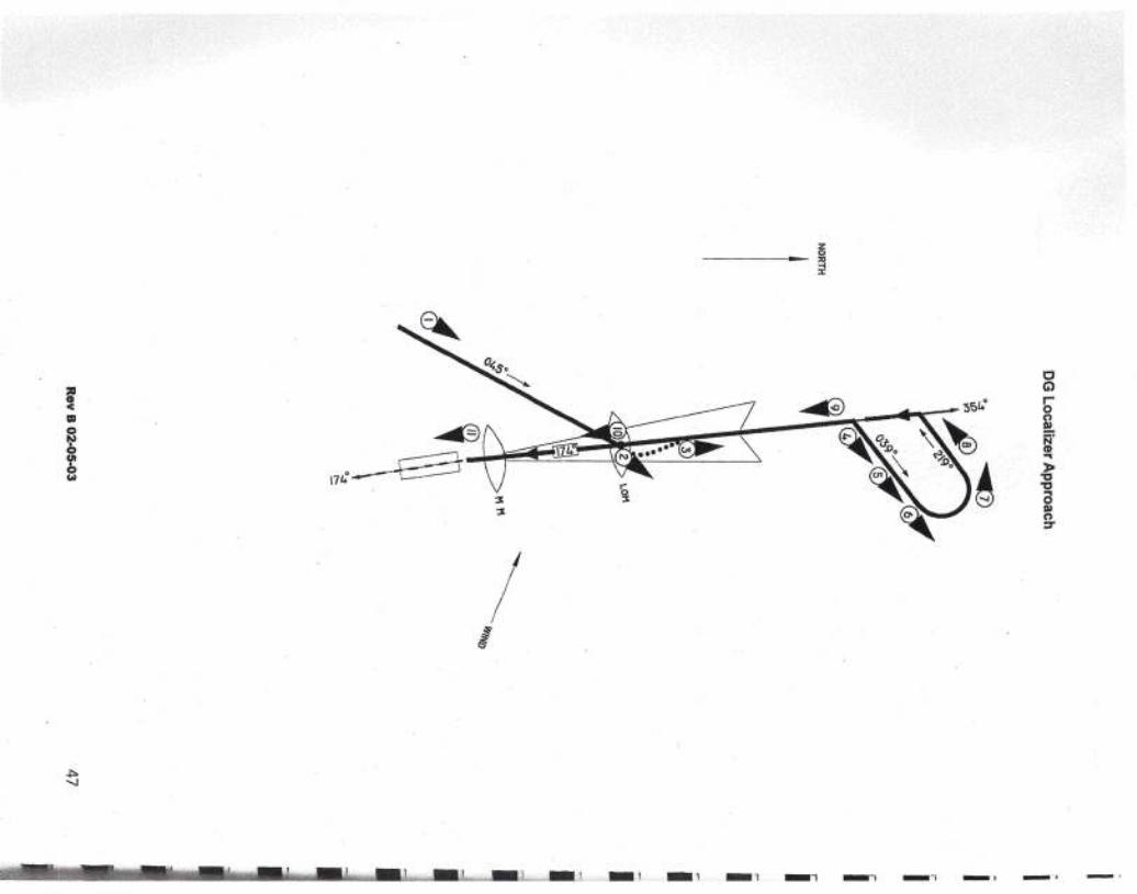
Step 1HOG/ALT. The localizer orILS approach begins.with atransition from the enroutestructure to the outercompass locator {L01J!).The heading bug $ 'l>..."Sdroselect the desired r.earll~.The aircraft's attirJ.:Ze m~'be controlted iJ:f memodifier SWITchor furo"J;7ithe use of the 2l'Jttirlemode.Step 2REVIARM AlT. Uponreaching the LOM, turn theheading bug to theoutbound course of the ILSand press the REV svlitch.The autopilot will interceptand track outbound.
Step 3REVlCPL ALT. Upontracking the localizer, thesystem will compensate forcrosswind and enter the'soft" mode.
Step 4HOG/AIT or ALT. At theappropriate time, press theHOG switch to begin theprocedure turn. Altitudeappropriate to this phase ofthe approach should becontrolled using ALT AIT orVS as necessary.
Step 5HOG/ALT. Proceedoutbound in the procedureturn until sufficient time haselapsed to assure proper re-interception.
46
/
_1
zo_ ::0-I:l:
_. -'

DG Localizer Approach
I
Step 6HOG/ALTLead the aircraft through theprocedure turn by movingthe heading bug in th.edirection of the turn.
I Step 8APRARM/ALTTurn the heading bug to theinbound front course of theILS and press the APRswitch. The autopilot willestablish a 45 intercept tothe localizer. When thelocalizer is less than 98% offull scale, GS ARM will bedisplayed to indicate theautopilot is armed forlideslo e.
Step 7HOG/ALTContinue to lead the aircre:!through the turn.
I
II Step 9
APR CPUAL T/GS ARMAfter intercept, the systemwill correct for crosswind andenter into the "soft" mode.Internal radio gains andbank angles will be limited.
IStep 10APR CPUGS CAPAs the glide slope beam iscaptured, ALT will beremoved. The system willtrack the localizer and glideslope. Power changesshould be made in. smallincrements as necessary tomaintain correct airspeed.
I Step 11HOG/AnOnce the aircraft reachesminimum, disconnect theautopilot. If a missedapproach is required,disconnect the autopilot andestablish desired climbattitude and airspeed. Whenappropriate press HDG andAn and en a e auto ilot.
III
Rev B 02·05·03 48
I

- -~\
!
I
I
I
II
IIIII
IIIIIIII
DG Localizer Back Course
\Pto,I,,,
ill~
NORTH
Rev 8 02-05-03 . 50

OG Localizer Back Course
Rev B 02-05-03
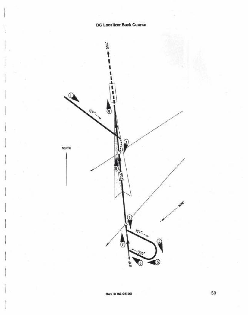
Step 5HOG/ALTLead the aircraft through theprocedure turn by movingthe heading bug in thedirection of the turn.
I
I
IIIIIJ-I
JI1-I
1
511
1
Step 1HOG/ALTThe localizer back courseapproach begins with atransition from an enroutestructure to intercept theback course outbound. Analternate method would beto set the inbound frontcourse with the heading bugand press the APR switch toset up a 450 intercept to theback course.Step 2APRCPUALTAfter the intercept, autopilotwill track the outboundcourse & compensate for
- any crosswind and begin'soft" mode.
Step 3HOG/ATT VS or ALTAt the appropriate time,press the HOG switch tobegin the procedure turn.Altitude appropriate to thisphase of the approachshould be controlled usingALT, VS or ATT asnecessary
Step 4HOG/ALTProceed outbound in theprocedure turn until suffi-cient time has elapsed toassure proper re-interception.

II
IIIIIIIIIIIIIIIII
DG Localizer Back Course
0.j'
II)to,,I,I
ill~
NORTH
Rev B 02.05-03 52

DGLocalizer Back Course
Step 6REVARMJALTAs the aircraft continues toturn, set the heading bug tothe inbound procedure turnheading. Press the REVswitch. The autopilot will setup a 45 intercept.
Step 7REV CPUATT or VSAfter the on course turn iscompleted, the system willenter the "soft" mode to limitradio authority and bankangles and to correct forcrosswind. Control altitudeand airspeed as appropriatefor the approach.Step 8HDG/ATTOnce the aircraft reachesminimums, disconnect theautopllot. If a missedapproach is required,disconnect the autopilot andestablish desired climbattitude and airspeed.When appropriate pressHDG and ATT and engageauto ilot.
Rev B 02-05-03 53