Embed Size (px)
Citation preview

PERPUSTAKAAN UMP
111111111111111111111111111111111111111 III 1111 0000103245
LOCATION-AWARE SYSTEM USING
BLUETOOTH LOW ENERGY
BEACONS
LAW CHIN HAO
THESIS SUBMITTED IN FULFILMENT OF THE DEGREE OF
COMPUTER SCIENCE (SOFTWARE ENGINEERING)
FACULTY OF COMPUTER SYSTEM AND SOFTWARE ENGINEERING
UNIVERSITI MALAYSIAPAH6-
2014

ABSTRACT
Bluetooth Low Energy (BLE) is a wireless technology with low power consumption that can be used by newer Bluetooth devices. This research focuses on implementing a way to deliver location based information from a content management system (CMS) to a mobile application by using location detection. The location detection feature of the mobile application uses beacon devices that run under BLE for positioning. By adding location awareness feature into a mobile application, mobile users can quickly find information relevant to their current position.
lv

ABSTRAK
Bluetooth Low Energy (BLE) adalah sejenis teknologi tanpa wayar yang boleh beroperasi dengan hanya menggunakan tenaga yang rendah. Kegunaan BLE adalah sangat luas dan boleh dipakai oleh pelbagai jenis peranti Bluetooth yang baru. Kajian mi fokus kepada penghasilan satu kaedah bagi penghantaran informasi berasaskan tempat daripada satu sistem pengurusan kandungan (CMS) ke satu applikasi telefon pintar menggunakan teknologi penentuan tempat. Kaedah yang digunakan untuk penentuan tempat ialah menggunakan peranti petunjuk bernama yang memakai teknologi BLE untuk penghantaran signal. Dengan penambahan fungsi kesedaran lokasi dalam aplikasi mobil, pengguna mobil dapat mencari informasi berkaitan dengan lokasi terkini dengan lebih cepat.
is

IMI
TABLE OF CONTENTS
DECLARATION 1
SUPERVISOR'S DECLARATION .......................................................... II
ACKNOWLEDGEMENT ....................................................................III
ABSTRACT ...................................................................................... IV
ABSTRAK .......................................................................................... V
TABLE OF CONTENTS ...................................................................... VI
LIST OF FIGURES .......................................................................... VIII
LIST OF TABLES ................................................................................ X
CHAPTER 1 INTRODUCTION .............................................................. 1
1.1 INTRODUCTION .......................................................................... 1 1.2 BACKGROUND ........................................................................... 1 1.3 PROBLEM STATEMENT ................................................................. 3 1.4 OBJECTIVES.............................................................................. 3 1.5 SCOPES ................................................................................... 4 1.6 THESIS ORGANIZATION................................................................. 5
CHAPTER 2 LITERATURE REVIEW ..................................................... 6
2.1 INTRODUCTION .......................................................................... 6 2.2 BLUETOOTH Low ENERGY ............................................................ 6
2.2.1 BLUE TOOTHLO WENERGYARCHITECTURE..................................................... 10 2.2.2 BLUETOOTHLOWENERGYBEACONARCHITECTURE ....................................... 10
2.3 BLUETOOTH Low ENERGY BEACON ................................................ 12 2.3.1 CONFIGURATIONPARAMETERS ...................................................................... 13 2.3.2 SIGNAL STRENGTH......................................................................................... 15
2.4 RELATED WORK ....................................................................... 16 2.4.1 BLUEMALL ................................................................................................... 17 2.4.2 BLuEAD ....................................................................................................... 19 2.4.3 BLE BEA CON PHYSICAL ITEM ADVERTISING SYSTEM ........................................ 21
2.5 CASE STUDY (BLOCK X, Y, Z) ....................................................... 23 2.6 BLUETOOTH PROXY ................................................................... 24 2.7 CONCLUSION/SUMMARY.............................................................. 25
CHAPTER 3 METHODOLOGY ............................................................. 26
3.1 INTRODUCTION ......................................................................... 26 3.2 RESEARCH METHODOLOGY........................................................... 26
3.2.1 LITERATUREREVIEW ..................................................................................... 27 3.2.2 PLANNING ..................................................................................................... 27 3.2.3 DESIGN......................................................................................................... 28 3.2.4 IMPLEMENTATION ......................................................................................... 28 3.2.5 TESTING & EVALUATION ............................................................................... 28 3.2.6 RESULTANALYSIS .......................................................................................... 28
3.3 SYSTEM ARCHITECTURE .............................................................. 29

vii
3.3.1 SYSTEM OVER VIEW •29 3.3.2 INHERE MOBILE APPLICATION......................................................................31 3.3.3 CONTENT MANA GEMENT SYSTEM (CMS) .......................................................35 3.3.4 CMS WEB SERVICE ....................................................................................... 38 3.3.5 BEACON CONFIGURATION.............................................................................40 3.3.6 BLUETOOTHPROXY ......................................................................................42
CHAPTER 4 DESIGN & IMPLEMENTATION ......................................... 43
4.1 INTRODUCTION ......................................................................... 43 4.2 DEVELOPMENT ENVIRONMENT....................................................... 43
4.2.1 BEACON CONFIGURATION............................................................................. 44 4.3 INHERE MOBILE APPLICATION....................................................... 45
4.3.1 DEVELOPMENT ENVIRONMENT...................................................................... 45 4.3.2 BEACON SIGNALS DETECTION ....................................................................... 45 4.3.3 CONNECTINGBLUETOOTHPROrJ' ................................................................. 48
4.4 CONTENT MANAGEMENT SYSTEM................................................... 49 4.4.1 FILE STR UCTURE........................................................................................... 49 4.4.2 DATABASE..................................................................................................... 49
4.5 WEB SERVICE .......................................................................... 50 4.5.1 DATABASE QUERY......................................................................................... 50 4.5.2 GENERATE JSONRESPONSE ......................................................................... 51
4.6 BLUETOOTH PROXY ................................................................... 52 4.6.1 SERVER ......................................................................................................... 52 4.62 SER VICE ............................................................. ........................................... 52 4.63 PROXTREQUESTHANDLING .......................................................................... 54
CHAPTER 5 RESULT & DISCUSSION ................................................... 56 5.1 RESULT ANALYSIS ...................................................................... 56
5.1.1 CONTENT MA NA GEMENT SYSTEM.................................................................... 57 5.1.2 INHERE MOBILE APPLICATION...................................................................... 59 5.1.3 WEB SERVICE ................................................................................................ 6] 5.1.4 BLUETOOTHPROXY ....................................................................................... 62
5.2 CONSTRAINTS .......................................................................... 63 5.2.1 DEVELOPMENT CONSTRAINTS........................................................................ 63 5.2.2 SYSTEM CONSTRAINTS ................................................................................... 64
CHAPTER 6 CONCLUSION ................................................................. 65
6.1 SUMMARY................................................................................ 65 6 .2 FUTURE WORKS........................................................................ 66
REFERENCES ................................................................................... 67
APPENDIX A..................................................................................... 70
APPENDIXB ..................................................................................... 71
APPENDIX C..................................................................................... 72
APPENDIX D..................................................................................... 73
APPENDIX E..................................................................................... 74
APPENDIXF ..................................................................................... 75

LIST OF FIGURES
FIGURE 2.1: BLE LINK LAYER STATE MACHINE ADOPTED FROM [17] ..............................7
FIGURE 2.2: BLUETOOTH Low ENERGY ARCHITECTURE................................................. 10
FIGURE 2.3: BLUETOOTH Low ENERGY BEACON ARCHITECTURE................................... 10
FIGURE 2.4: A KONTAKT.IO BEACON DEVICE ............................... . ................................... 12
FIGURE 2.5: BLUEMALL SYSTEM ARCHITECTURE ........................................................... 17
FIGURE 2.6: BLuEAD SYSTEM ARCHITECTURE ............................................................... 19
FIGURE 2.7: MOBILE APPLICATION OF THE ADVERTISING SYSTEM [26]........................... 21
FIGURE 2.8: PHYSICAL ARCHITECTURE DESIGN FOR BLE BEACON PHYSICAL ITEM ADVERTISING SYSTEM [26] ...................................................................................... 21
FIGURE 2.9: MAP LAYOUT OF BLOCK X, Y AND Z.......................................................... 23
FIGURE 2.10: BLUETOOTH PROXY AS A GATEWAY FOR INTERNET ACCESS ...................... 24
FIGURE 2.11: RFCOMM BLUETOOTH COMMUNICATION LINK ADOPTED FROM [27] ...... 25
FIGURE 3.1: PROJECT'S RESEARCH METHODOLOGY ........................................................ 27
FIGURE 3.2: INHERE ARCHITECTURE ............................................................................... 29
FIGURE 3.3: USE CASE OF THE INHERE CONTENT DELIVERY SYSTEM.............................. 30
FIGURE 3.4: CONTEXT DIAGRAM OF INHERE MOBILE APPLICATION .............................. 31
FIGURE 3.5: USER INTERFACE DESIGN OF THE INHERE MOBILE APPLICATION................. 32
FIGURE 3.6: ACTIVITY DIAGRAM OF INHERE MOBILE APPLICATION................................ 33
FIGURE 3.7: FLOWCHART FOR "SCAN LOCATION" .......................................................... 34
FIGURE 3.8: CONTEXT DIAGRAM OF CMS ...................................................................... 35
FIGURE 3.9: USE CASES OF INHERE CMS ........................................................................ 35
FIGURE 3.10: DATA FLOW DIAGRAM LEVEL 0 OF CMS ................................................. 36
FIGURE 3.11: ENHANCED ENTITY-RELATIONSHIP (EER) MODEL OF DATABASE ............. 37
FIGURE 3.12: UML REPRESENTATION OF THE JSONREsP0NsE OBJECT .......................... 39
FIGURE 3.13: BEACON PLACEMENT FLOOR PLAN ............................................................ 41
FIGURE 3.14: SEQUENCE DIAGRAM SHOWING THE TASKS OF A BLUETOOTH PROXY ....... 42
FIGURE 4.1: FLOWCHART OF LOCATION DETECTION ALGORITHM ................................... 47
FIGURE 4.2: ALGORITHM OF BLUETOOTH PROXY SERVICE ............................................ 53
FIGURE 4.3: ALGORITHM OF PROXY REQUEST HANDLING.............................................. 55
FIGURE 5.1: VIEWING NOTIFICATIONS FROM INHERE CMS............................................ 57
Viii

lx
FIGURE 5.2: EDITING A NOTIFICATION ENTRY IN INHERE CMS...................................... 58
FIGURE 5.3: SCREENSHOT OF INHERE MOBILE APPLICATION .......................................... 59
FIGURE 5.4: NOTIFICATIONS CHANGES WHEN USER MOVES TO ANOTHER ZONE ..............60
FIGURE 5.5: SAMPLE OUTPUT FROM THE INHERE WEB SERVICE......................................61
FIGURE 5.6: SAMPLE CONSOLE LOG FROM THE BLUETOOTH PROXY APPLICATION .........62

x
LIST OF TABLES
TABLE 2.1: COMPARISON OF BLUETOOTH Low ENERGY (BLE) & NEAR FIELD COMMUNICATION(NFC)...........................................................................................9
TABLE 2.2: KONTAKT.IO BEACON TECHNICAL SPECIFICATIONS ......................................13
TABLE 2.3: Tx POWER VALUES OF KONTAKT.IO BEACON ...............................................14
TABLE 2.4: FEATURES OF BLuEMALL ............................................................................. 18
TABLE 2.5: FEATURES OF BLUEAD .................................................................................20
TABLE 2.6: FEATURES OF BLE BEACON PHYSICAL ITEM ADVERTISING SYSTEM..............22
TABLE 3.1: COMMON CONFIGURATIONS SHARED BY ALL BEACONS ................................40
TABLE 3.2: BEACON ALLOCATION AND ITS MAJOR PARAMETER ......................................41
TABLE 4.1: PASSWORDS OF BEACONS .............................................................................44
TABLE 4.2: IMPORTANT FILES IN INHERE CMS...............................................................49

CHAPTER 1
INTRODUCTION
1.1 INTRODUCTION
Chapter 1 of this thesis report introduces the InHere location-aware content
delivery system that uses Bluetooth Low Energy (BLE). This chapter contains six
sections, which includes Introduction, Background, Problem Statement, Objective, Scope
and Thesis Organization.
1.2 BACKGROUND
Bluetooth Low Energy, (BLE or Bluetooth Smart) is a new technology that allows
Bluetooth signals to be transmitted with lower power consumption while maintaining a
similar communication range [1] [2]. Proximity beacon device that based on BLE
technology can provide indoor and outdoor positioning service to BLE ready mobile
devices that supports Bluetooth 4.0 [2] [3]. Inside a building, Bluetooth indoor
positioning would be more practical than using the Global Positioning System (GPS)
because the latter requires a view to the clear sky for consistent satellite communication
[4]. Bluetooth micro-location technology therefore opened up possibilities for context and
location awareness feature to be integrated into mobile applications.
I

BLE proximity beacon is a low-powered transmitter device that will broadcast a
signal at a certain interval to indicate their presence [5]. Without the need of pairing, a
Bluetooth Smart ready device will be able to receive the signal when in range. The signal
strength (RSSI) received by the mobile device will be used to estimate the distance
between the user device and the beacon [6]. Mobile applications can be designed to
dynamically perform action or display information paired to the nearest beacon. The
terminology for such intelligence is called location awareness.
The BLE beacon technology is featured by Apple in iOS7 and Apple trademarked
it as iBeacon. However, this technology is not patented by Apple [7]. There was another
open beacon specification named AltBeacon which was proposed by Radius Networks
[8]. BLE beacon technology is in fact multi-platform supported and can be used on any
Bluetooth Smart ready devices [9]. For instance, Android operating system had
introduced native BLE support starting Android 4.3. Android application will be able to
read signals from BLE by using the Android API Level 18 [10]. Due to the base support
of BLE in the newly released line of smartphone devices, more beacon integrated
applications is expected to be delivered in the near future.
Real-world application of beacon technology already exists in year 2013. Macy' s,
Inc. is a retailer in United States that uses an app called Shopkick to greet their potential
customers as soon as they entered the store, additionally to sending promotion and
discount notifications to the mobile users [3]. PayPal also utilize beacon technology as a
new way to make payment. Mobile users do not have to swipe their credit card during
payment checkout [11]. Major League Baseball also made an app that will show user
information about nearby statues and points of interest. The app, called "Major League
Baseball" is also capable to guide users in navigating around the stadium [12].
Privacy in beacon technology is one of the concerns discussed by public. It is
important to point out that BLE beacon does not track the user or collecting data from
mobile device [13]. The beacon will only send out signals for the related app to perform
micro-location detection. If the user is concerned about their privacy, the user is able to
opt-out by choosing not to install the mobile app [13] [14].
BLE beacon technology is a very powerful addition for mobile computing if it is
fully implemented in our daily life. This technology improves mobile user experience by
implementing context-aware features to the mobile application. At some point it may
3
even replaces the need of scanning QR code or reading NFC tags [2]. As mobile
computing industry is rapidly evolving, BLE beacon technology should be further
explored to be used in the enhancement of mobile user experience.
1.3 PROBLEM STATEMENT
Mobile application allows the access of information even when the user is away
and does not have access to a personal computer. Wireless network technology had totally
changed the way how information is being shown in mobile application. With internet
access, contents of mobile application are getting more dynamic and interesting. In
general, this research will be focusing on integrating BLE beacon technology into a
mobile application that shows dynamic information related to user's current location, or
also known as micro-location contents.
Location awareness feature is very versatile and can be applied in mobile
applications to improve their usability. With location awareness, an application is able to
use the location data to help user in searching, geotagging, navigating, understanding
point of interest and much more. Location awareness technology can be applied in many
domains, such as tourism and navigation. In airport for example, an application can guide
the user to the boarding gate using location data. As mobile user pool growing larger each
year, delivery of micro-location content in mobile application will benefits more users in
future.
The main issue in this research is to determine if Bluetooth Low Energy
technology can be used for location-aware content delivery system. If the result shows
BLE technology is favorable, another question arises is how BLE technology can be used
in the implementation of such system.
1.4 OBJECTIVES
There are two objectives in this project:
To develop a location-aware content delivery system using Bluetooth Low
Energy technology.
ii. To develop the prototype by using BLE beacon as a positioning device for
the location-aware content delivery system.

4
1.5 SCOPES
• The content delivery application (CDA) will be developed as an Android
application.
• Targeted version of Android operating system for running the application is
Android 4.3+.
• A simple web content management system (CMS) will be developed for
administrator to manage dynamic information.
• For mobile application, event notifications shown for each location each
time is limited to the latest 50.
• Three BLE beacons will be used for the realization of idea.
• A Bluetooth proxy application will be developed.
• Case study: Teaching & learning area (Block X, Y, Z) in University of
Malaysia, Pahang.

5
1.6 THESIS ORGANIZATION
This thesis report is comprised of six chapters. Phase I of the research will focus
on Chapter 1: Introduction, Chapter 2: Literature Review and Chapter 3: Methodology.
Phase II of the research will focus on Chapter 4: Design & Implementation, Chapter 5:
Results and Discussions and Chapter 6: Conclusion.
Chapter 1: Introduction contains overview to the research topic along with the
problem statement, objectives and scopes of the project. Chapter 2: Literature Review
summarizes the literature review of books, journals and articles related to the project.
Technique, algorithm and hardware configurations will be decided after all the literatures
in this chapter have been studied. Chapter 3: Methodology will discuss the method and
processes that will be used for the development of the project. It will also include a project
plan as reference.
Chapter 4: Design & Implementation will explain in detail about the
implementation of the project, including how to build a working prototype using the
technique chosen in Chapter 3. Sample source code will be included to clarify the
algorithm or process flow of the system. In Chapter 5: Results and Discussions, the results
acquired from the testing and evaluation of the system will be included along with related
discussions and analysis. Chapter 6: Conclusion will have a conclusion to the project. The
results from evaluation and review of objectives will be used to determine the fulfillment
of the research objectives. The effect of the implementation will also be included in this
chapter.

CHAPTER 2
LITERATURE REVIEW
2.1 INTRODUCTION
Chapter 2 of this thesis summarizes the literature review related to this project.
Related journal papers from past year researches are studied and also summarized. Based
on the reviews, a most relevant project will be chosen as reference guide to assist the
implementation of this project. Various techniques and methods will also be discussed,
along with comparison and proof.
2.2 BLUETOOTH LOW ENERGY
Bluetooth Low Energy, (BLE or Bluetooth Smart) is a new Bluetooth technology
developed by Bluetooth Special Interest Group (SIG) featuring low energy wireless
transmission. Introduced in 2006 by Nokia, BLE was once known as Wibree but later
changed its name when it was merged into Bluetooth Core Specification 4.0 [15]. BLE
transmits signals using a 2.4 GHz Industrial Scientific Medical (ISM) band [16] that is
dedicated for industrial, scientific and medical purposes only.

7
The BLE protocol stack consists of a controller part that has Link Layer and
Physical Layer. The link layer of BLE is similar to a state machine. A BLE device can
have more than one state machine running at any time and it can be in any of these states:
Standby, Advertising, Scanning, Initiating or Connected [17].
II igure 2. 1: bLt LinK Layer state macnine aaopteu trom [1/]
In Standby state, the device does not transmit or receive packet. It can change to
another state such as Advertising, Scanning or Initiating. In Advertising state, the device
will broadcast advertisement in advertising channels. When scanning, the device will scan
for advertisers and when initiating, the device will initiate connection to the advertiser.
A BLE device can have one of the following roles: Advertiser, which is a device
that transmit advertising packets; Scanner, which is a device that listens to the
advertisement packets without the intention of making connection; and Initiator, a device
that attempt to connect to an Advertiser [18].
A connection is required for two Bluetooth devices to communicate with each
other. For a connection to form, an Advertiser will enter Advertising state and broadcast
a message indicating that it is connectable. When the message is detected by another
device, that device will change to Initiating state and send a connection request to the
Advertiser. This device will be called as the Initiator. When the connection request is
accepted, both devices are connected and data communication can be made. The Initiator
will become Master and the Advertiser will become Slave.
Master device will be able to control the transmission and communicate with more
than one Slave at a time. In contrast, a Slave can only communicate with single Master
device. A BLE device cannot become master and slave at the same time. The role is also
non-switchable. In order to save energy, slave is inactive by default and only wake up
periodically to listen for signals [1 8].
Physical Layer of BLE has two types of radio frequency channels. The first type
is advertising channels that will be used to send frequencies related to device discovery,
connection and broadcasting [18]. This kind of channel will be used by broadcasting
devices, where their advertising packet will be sent out continuously at certain intervals.
The other type of radio frequency channel is data channels where it will be used for data
communication.
Due to its power-saving characteristic, BLE is widely used in healthcare, fitness
and sport applications. The Bluetooth SIG also predicted that more than 90% ofBluetooth
enabled smartphones will support BLE by 2018 [19]. Generally, BLE can be used in any
contactless application just like the Near Field Communication (NFC). However, NFC
operates in a very short range which is typically less than 20cm. This makes NFC become
less flexible or portable compared to BLE. The range advantage makes BLE a better
technology to be used in beacon devices.

Table 2.1: Comparison of Bluetooth Low Energy (BLE) & Near Field Communication (NFC)
OBluetooth Features SMART
BLE
NFC
Standardization Body Bluetooth SIG
ISO/IEC
Range Over 100 meters [20]
Less than 20 cm
Frequency 2.4 GHz 13.56 MHz
Bitrate 1 Mbit/s 424 kbit/s

Iff
2.2.1 Bluetooth Low Energy architecture
A single BLE packet can be measured up to 47 bytes. The protocol data unit (PDU)
segment in a BLE packet will have a 2 bytes header at its own. This header contains
information about the size and the type of the payload. Following the header is the actual
payload with MAC address of the device comes first, followed by the actual data [21].
PDU (2-39 bytes)
Preamble AcHeaderMAC Data CRC
I Address Address (up to 31 bytes) (3 bytes) L' byte), (4 bytes) j2 bytes_ (6 bytes) A.
Figure 2.2: Bluetooth Low Energy architecture
2.2.2 Bluetooth Low Energy beacon architecture
BLE beacons uses architecture modified from the BLE standard. They are
specialized for signal broadcasting and will be using the advertising channel in the
physical layer of BLE. Their advertising packet will be sent out in a regular interval. In a
normal beacon packet, all segments from a standard BLE packet are removed except the
PDU segment. All beacon advertisement data which is normally 30 bytes will be fitted
into the 31 bytes data segment.
Data (31 bytes)
Unused byte
UUID es) (2 bytes) (1 byte)
Tx Proximity Major Minor Pa Preamble . (9 bytes)
(16 bytes)
Figure 2.3: Bluetooth Low Energy beacon architecture

11
Packet structure similar to the structure shown in Figure 2.3 was adopted by most
beacon manufacturers. According to the datasheet provided by the project's beacon
manufacturer Kontakt.io , every packet from Kontakt beacons will have an identical 9
bytes preamble which is "02 01 06 1A FF 4C 00 02 15" [22]. These bytes are
manufacturer's identifier and also several flags that represent the operational mode of the
device. Following the preamble segment are Proximity Universally Unique Identifier
(UUID), Major number, Minor number and lastly the Tx Power segment, all in the form
of hexadecimal values. The detail of these segments will be further discussed in section
2.3.1.

12
2.3 BLUETOOTH LOW ENERGY BEACON
Figure 2.4: A Kontakt.io beacon device
A Bluetooth Low Energy beacon is a transmitter device that comprises a wireless
radio circuit board. It can broadcast BLE signals to nearby mobile devices. Any Bluetooth
Smart ready mobile devices should be able to detect the presence of a beacon as it gets
near to the beacon, provided it has the Bluetooth radio turned on. Running under BLE
technology, these beacons is powered by USB or a cell battery. A beacon can
continuously operate for years if running on cell battery depends on its configuration and
usage. With low amount of energy required for daily operation, these beacons can
function as a proximity detector suitable to be used for positioning. By analyzing signal
strength, mobile applications are able to estimate the distance between the mobile device
and the beacon. The application can then react differently according to the distance
approximation, thus providing context-awareness or location based services in the
application.
The beacons used in this project were manufactured by a company called
Kontakt.io . The 50g beacon device is measured 55mm x 55mm x 15mm and is encased
by recyclable ABS plastic. Hardware of the device is mainly made up of a Bluetooth
Smart IC and an ARM processor. A CR2477 coin cell battery will be used to power up
the device. It can be easily replaced if the battery is depleted.
13
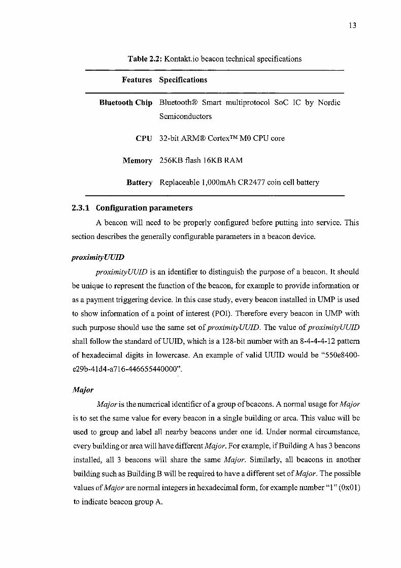
Table 2.2: Kontakt.io beacon technical specifications
Features Specifications
Bluetooth Chip Bluetooth® Smart multiprotocol SoC IC by Nordic
Semiconductors
CPU 32-bit ARMS CortexTM MO CPU core
Memory 256KB flash 16KB RAM
Battery Replaceable 1 ,000mAh CR2477 coin cell battery
2.3.1 Configuration parameters
A beacon will need to be properly configured before putting into service. This
section describes the generally configurable parameters in a beacon device.
proximity UUID
proximity UUID is an identifier to distinguish the purpose of a beacon. It should
be unique to represent the function of the beacon, for example to provide information or
as a payment triggering device. In this case study, every beacon installed in UMP is used
to show information of a point of interest (P01). Therefore every beacon in UMP with
such purpose should use the same set of proximity UUJD. The value of proximilyUUlD
shall follow the standard of UUID, which is a 128-bit number with an 8-4-4-4-12 pattern
of hexadecimal digits in lowercase. An example of valid UUID would be "550e8400-
e29b-41d4-a71 6-446655440000".
Major
Major is the numerical identifier of a group of beacons. A normal usage for Major
is to set the same value for every beacon in a single building or area. This value will be
used to group and label all nearby beacons under one id. Under normal circumstance,
every building or area will have different Major. For example, if Building A has 3 beacons
installed, all 3 beacons will share the same Major. Similarly, all beacons in another
building such as Building B will be required to have a different set of Major. The possible
values of Major are normal integers in hexadecimal form, for example number "1" (OxO 1)
to indicate beacon group A.

14
Minor
Minor is the numerical identifier of a single beacon. Minor served as an id to
distinguish a single beacon from a set of beacon with same Major. Therefore, every
beacon within a same Major set will need to have a unique Minor value. Similar to Major,
the possible values of Minor are normal integers in hexadecimal. For example, "1" (Hex:
OxOl) will be used for beacon located in entrance and "2" (Hex: 0x02) is for beacon
located in enquiry counter.
Tx Power
Tx Power is a numerical reference value that represents the transmission power
level of the signal measured at 1 meter from the beacon. The Tx Power value range of a
Kontakt beacon is between -30 to 4 (dBm), with 4 dBm being the highest power setting
[22]. The distance estimation process using Tx Power will be further discussed in section
2.3.2.
Table 2.3: Tx Power values of Kontakt.io beacon
Hex Decimal (dBm)
OxE2 -30
OxEC -20
OxFO -16
OxF4 -12 (Default setting)
OxF8 -8
OxFC -4
0x04 4

15
Advertising intervals
Advertising intervals is the timer for when a beacon signal should be sent out
regularly. This setting will indirectly affect the battery life of a beacon, thus it is important
to find a balanced setting between sustainable battery life and an effective broadcast
frequency. For Kontakt beacons, the interval can be set at a time between 20 milliseconds
to 10 seconds. The value has to be converted into hexadecimal using the formula:
milliseconds Interval (Hex)
0.625
For example, a beacon with 10 seconds interval will be set to 0x3E80 (Decimal:
16000), calculated by 10000 ms / 0.625 = 16000.
2.3.2 Signal strength
Received Signal Strength Indication (RSSI) obtained in a mobile device will be
used to estimate the proximity of a beacon. The closer the distance of device to the beacon,
the higher the actual RSSI reading will be. This actual RSSI reading is also sometimes
being referred as the measured power of beacon.
Tx Power value of a beacon can be interpreted as the expected signal strength
(RSSI) received by a mobile device from 1 meter away. Changing the Tx Power value is
same as changing the expected RSSI reference value. The Tx Power or expected RSSI
can be used as a reference when estimating the proximity of a beacon.
For example, if the Tx Power is equal to 226 (Hexadecimal: OxE2), expected RSSI
from 1 meter away would be the two's complement of 226, or 256-226 = 30. Therefore,
the expected RSSI received is -30 dBm if the device is located at 1 meter away. By
comparing the expected RSSI with the actual RS SI data obtained, the distance of the
beacon can be estimated. In this case, if a mobile device reads a RSSI higher than -30
dBm, it can be interpreted that the mobile device is less than 1 meter away from the
beacon. However, the distance is only estimation and might be erroneous because
obstacles such as walls and peoples can weaken the signals [23].
16
2.4 RELATED WORK
Researchers had proved that Bluetooth technology can be used for mobile
advertising services. Bluetooth mobile advertising is normally done as location-based
service, where the mobile user's current location or environment will affect the advertised
contents. Traditional approach from past researches uses a set of computers that act as a
group of Bluetooth access points. These access points will scan for mobile devices and
then attempt to send an advertisement to it. By comparing with the new beacon approach,
traditional method is more proactive and requires more computing power for the server
hardware. There are a few mobile advertising or beacon tagging systems that already exist.
Three of these systems with highest similarity are studied and summarized.