Embed Size (px)
Citation preview
AALTO UNIVERSITY SCHOOL OF SCIENCE AND TECHNOLOGY Faculty of Electronics, Communications and Automation Department of Communications and Networking Tuomas Järvinen
Location System solution in TErrestrial Trunked RAdio (TETRA)
Professional Mobile Radio networks
Master's Thesis submitted in partial fulfillment of the requirements for the degree of Master of Science in Espoo, Finland. 22th January 2010 Supervisor: Professor Riku Jäntti Instructor: Mika Laitinen, M.Sc.
AALTO UNIVERSITY SCHOOL OF SCIENCE AND TECHNOLOGY
ABSTRACT OF THE MASTER’S THESIS
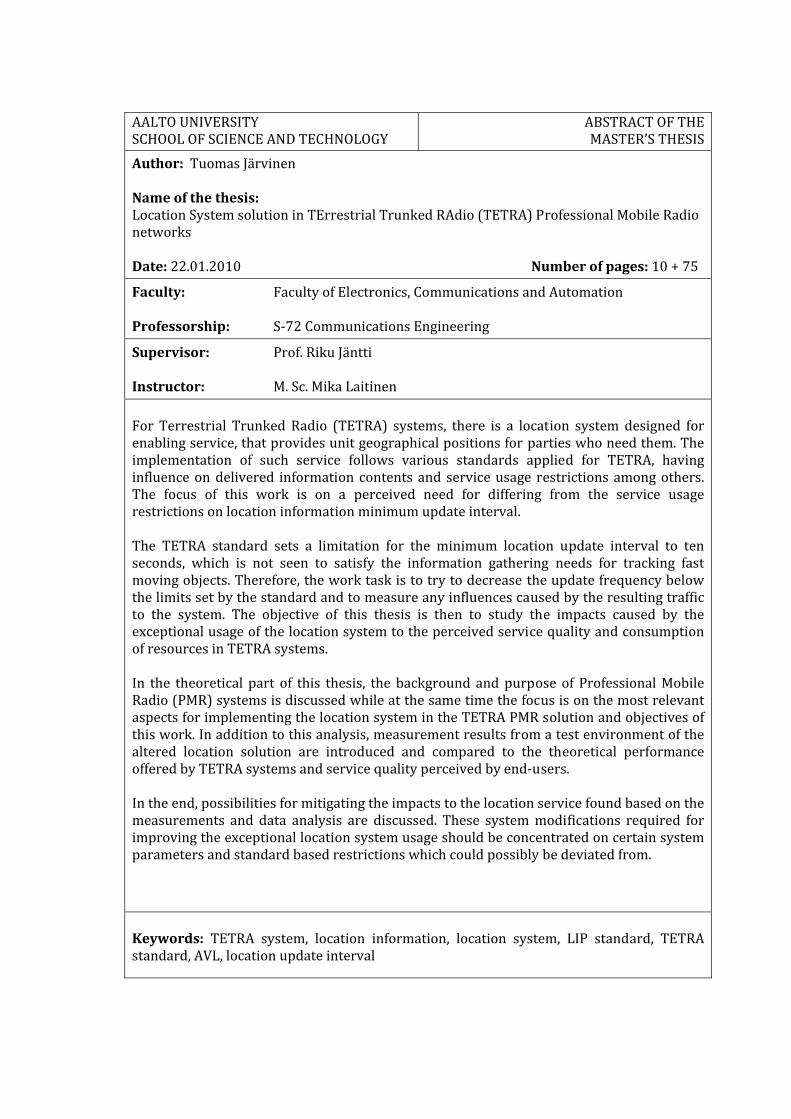
Author: Tuomas Järvinen Name of the thesis: Location System solution in TErrestrial Trunked RAdio (TETRA) Professional Mobile Radio networks Date: 22.01.2010 Number of pages: 10 + 75
Faculty: Faculty of Electronics, Communications and Automation Professorship: S‐72 Communications Engineering
Supervisor: Prof. Riku Jäntti Instructor: M. Sc. Mika Laitinen For Terrestrial Trunked Radio (TETRA) systems, there is a location system designed for enabling service, that provides unit geographical positions for parties who need them. The implementation of such service follows various standards applied for TETRA, having influence on delivered information contents and service usage restrictions among others. The focus of this work is on a perceived need for differing from the service usage restrictions on location information minimum update interval. The TETRA standard sets a limitation for the minimum location update interval to ten seconds, which is not seen to satisfy the information gathering needs for tracking fast moving objects. Therefore, the work task is to try to decrease the update frequency below the limits set by the standard and to measure any influences caused by the resulting traffic to the system. The objective of this thesis is then to study the impacts caused by the exceptional usage of the location system to the perceived service quality and consumption of resources in TETRA systems. In the theoretical part of this thesis, the background and purpose of Professional Mobile Radio (PMR) systems is discussed while at the same time the focus is on the most relevant aspects for implementing the location system in the TETRA PMR solution and objectives of this work. In addition to this analysis, measurement results from a test environment of the altered location solution are introduced and compared to the theoretical performance offered by TETRA systems and service quality perceived by end‐users. In the end, possibilities for mitigating the impacts to the location service found based on the measurements and data analysis are discussed. These system modifications required for improving the exceptional location system usage should be concentrated on certain system parameters and standard based restrictions which could possibly be deviated from.
Keywords: TETRA system, location information, location system, LIP standard, TETRA standard, AVL, location update interval
AALTO‐YLIOPISTON TEKNILLINEN KORKEAKOULU
DIPLOMITYÖNTIIVISTELMÄ
Tekijä: Tuomas Järvinen Työn nimi: Paikkatietojärjestelmäratkaisu TErrestrial Trunked RAdio (TETRA) Professional Mobile Radio verkoissa Päivämäärä: 22.01.2010 Kieli: Englanti Sivumäärä: 10 + 75
Tiedekunta: Elektroniikan, tietoliikenteen ja automaation tiedekunta Professuuri: S‐72 Tietoliikennetekniikka
Valvoja: Prof. Riku Jäntti Ohjaaja: DI Mika Laitinen TETRA‐järjestelmään (TErrestrial Trunked RAdio) on toteutettu paikkatietojärjestelmä tarjoamaan palvelua yksiköiden maantieteellisen paikkatiedon välittämiseksi sitä tarvitseville tahoille. Tämän palvelun toteutus noudattaa TETRA:lle asetettuja standardeja muun muassa välitettävän tiedon sisällön sekä palvelun käytön rajoitusten osalta. Tässä työssä ollaan kiinnostuneita havaitusta tarpeesta poiketa standardoiduista palvelun käytön rajoitteista paikkatiedon lyhimmän päivitysvälin osalta. TETRA standardi rajoittaa pienimmän mahdollisen paikkatiedon päivitysvälin kymmeneen sekuntiin minkä ei ole todettu tyydyttävän nopeasti liikkuvien kohteiden seuraamiseen tarvittavaa tiedonkeruutarvetta. Niinpä tässä tutkimuksessa työnä on pyrkiä pienentämään tämä päivitysfrekvenssi alle standardien asettaman rajan ja teettämään mittauksia liikenteen myötä järjestelmään aiheutuvista vaikutuksista. Diplomityön tavoitteena on tutkia tämän poikkeuksellisesta paikkatietopalvelun käytöstä aiheutuvia seurauksia palvelun laadun ylläpidettävyyteen ja TETRA‐järjestelmän resurssien kulutukseen. Diplomityön teoriaosuudessa käydään läpi taustaa ammattikäyttöön suunnattujen matkapuhelinjärjestelmien (Professional Mobile Radio) tarkoitusperästä sekä lisäksi erityisesti keskitytään näihin kuuluvan TETRA ratkaisun olennaisimpiin osiin liittyen paikkatietosovelluksen toteutukseen ja työn tavoitteisiin. Tämän analyysin lisäksi esitellään muunnellusta paikkatietojärjestelmästä testiympäristössä saavutettuja mittaustuloksia ja vertaillaan näitä teoreettiseen TETRA‐järjestelmän tarjoamaan suorituskykyyn sekä tavoiteltuun loppukäyttäjän kokemaan palvelun laatuun. Lopuksi pohditaan mahdollisuuksia työn mittaustulosten sekä aineiston analyysin pohjalta kartoitettujen paikkatietopalveluun aiheutuneiden vaikutusten pienentämiseksi. Nämä poikkeavan toiminnallisuuden mahdollistavat järjestelmän muutostarpeet kohdistuisivat tiettyihin systeemin parametreihin ja standardien sanelemiin rajoituksiin joista voitaisiin mahdollisuuksien mukaan poiketa. Avainsanat: TETRA‐järjestelmä, paikkatieto, paikkatietojärjestelmä, LIP‐standardi, TETRA‐standardi, AVL, paikkatiedon päivitysväli

iv
Preface
I would like to thank my employer EADS Security & Communication Solutions for giving me the opportunity to write this thesis. My gratitude goes to my instructor Mika Laitinen, M.Sc, for the support and valuable comments throughout the work process. Also thanks goes to my colleagues who have given me advice and shared their expertise for enabling me to put the contents of this thesis together. I would also like to thank my supervisor, Professor Riku Jäntti from the Department of Communications and Networking in Helsinki University of Technology. Your feedback and comments helped me to finish the thesis. My thanks go also to William Martin of the Department of Communications and Networking for revising the language of the thesis. Most of all, I am very grateful for my wonderful and beloved wife Heidi, especially for her patience and support during my studies. Finally many thanks to my parents and family for supporting me towards this accomplishment. Espoo, Finland January 22, 2010 Tuomas Järvinen
v
Table of Contents
LIST OF ABBREVIATIONS VII
LIST OF FIGURES IX
LIST OF TABLES X
1 INTRODUCTION 1
1.1 Motivation of the thesis 1 1.2 Scope of the thesis 2 1.3 Structure of the thesis 3
2 PROFESSIONAL MOBILE RADIO (PMR) 4
2.1 Professional users of mobile radio 5 2.1.1 The PMR market sectors 6
2.2 Features of PMR systems 8 2.2.1 Location service and dispatching 10
2.3 PMR technologies 10 2.3.1 TETRA 11 2.3.2 Project 25 (P25) 12 2.3.3 TETRAPOL 13
3 TERRESTRIAL TRUNKED RADIO (TETRA) 14
3.1 The TETRA Standard 14 3.2 Trunked mode in TETRA 17 3.3 EADS TETRA infrastructure 18 3.4 TETRA data services 20
4 LOCATION SYSTEM SOLUTION IN TETRA 22
4.1 Requirements for the Location System in TETRA networks 23 4.2 The location server 25 4.3 Location system traffic types 26 4.3.1 Application layer protocols 27 4.3.2 Traffic profiles 28
vi
4.4 End‐user client applications 29 4.4.1 Time based applications 30 4.4.2 Event based applications 31
5 NETWORK AND CLIENT DIMENSIONING 32
5.1 Data bearers at the Air Interface 32 5.1.1 Layer 1 – The physical layer 33 5.1.2 Layer 2 – The data link layer 33 5.1.3 Layer 3 – The network layer 36
5.2 Location update message data payload 38 5.2.1 Location report messages 38
5.3 Protocol stack summary 40
6 TETRA AI CAPACITY 41
6.1 Location update transmission profile 41 6.2 Random access capacity 42 6.2.1 TETRA random access protocol 45
6.3 LIP short location report capacity 46
7 MEASUREMENTS 49
7.1 System throughput with modified Location System 50 7.2 Reception variance at end‐user side 55 7.3 Measurement summary 60 7.3.1 Aspects influencing the traffic performance during the measurements 62
8 CONCLUSIONS 66
REFERENCES 68
APPENDIX 1 70
APPENDIX 2 74
vii
List of abbreviations
AI Air Interface
APCO Association of Public Safety Organization Officials
API Application Programming Interface
APL Automatic Person Location
AVL Automatic Vehicle Location
BL Basic Link
CAD Computer Aided Dispatching
CDD Configuration and Data Distribution
CDF Cumulative Distribution Function
CMCE Circuit Mode Connection Entity
CP Control Physical channels
DMO Direct Mode Operation
DWS IF Dispatcher Workstation Interface
EADS European Aeronautic Defence and Space Company
ETSI European Telecommunications Standards Institute
FCS Frame Check Sequence
FDMA Frequency Division Multiple Access
GIS Geographic Information System
GPS Global Positioning System
GSM Global System for Mobile communications
GW IF Gateway Interfaces
ISDN Integrated Services Digital Network
ISI Inter System Interface
ISSI Inter Subsystem Interface
ISOOSI International Standardization Organization – Open Systems
Interconnection
LIP Location Information Protocol
LLC Logical Link Control
LMR Land Mobile Radio
LS Location System
LSI Line Station Interface
viii
MAC Medium Access Control
MCCH Main Control Channel
MLE Mobile Link Entity
MLP Mobile Location Protocol
NMI Network Management Interface
O&M Operations and Maintenance
OMA Open Mobile Alliance
P25 Project 25
PAMR Public Access Mobile Radio
PDU Protocol Data Unit
PEI Peripheral Equipment Interface
PLMN Public Land Mobile Network
PMR Professional Mobile Radio
SDS Short Data Service
SDSTL Short Data Service Transport Layer
SDU Service Data Unit
SwMI Switching and Management Infrastructure
TC Traffic Physical channels
TCH Traffic Channel
TCS TETRA Connectivity Server
TDMA Time Division Multiple Access
TEDS TETRA Enhanced Data Service
TETRA TErrestrial Trunked RAdio
TMO Trunked Mode Operation
UMTS Universal Mobile Telecommunications System
V + D Voice plus Data
VPN Virtual Private Networks
ix
List of Figures
Figure 2.1: PMR market sectors 6 Figure 2.2: TETRA Total Market Q3 2008 11 Figure 3.1: The TETRA interfaces 15 Figure 3.2: The TETRA Switching and Management Infrastructure (SwMI) 18 Figure 4.1: The complete TETRA LS 23 Figure 6.1: Throughput characteristics for slotted ALOHA 43 Figure 6.2: The slotted ALOHA throughput per second in TETRA systems 45 Figure 6.3: The TETRA system throughput for short location update reports 47 Figure 6.4: Comparison of single and two half slot length transmission throughputs 48 Figure 7.1: Comparison of throughputs of 1.2 second interval and the TETRA LS 52 Figure 7.2: Comparison of throughputs of 2.4 second interval and the TETRA LS 53 Figure 7.3: Comparison of the two measurement intervals 54 Figure 7.4: An Example of used CDF with offered traffic of 1.2 second interval 57
x
List of Tables
Table 2.1: Sectors of the PMR market 5 Table 2.2: PMR system implementation: P25 vs TETRA 13 Table 5.1: TETRA uplink slot capacities 33 Table 5.2: MAC‐ACCESS PDU 34 Table 5.3: MAC‐FRAG PDU 35 Table 5.4: MAC‐END‐HU PDU 35 Table 5.5: MAC‐END PDU 35 Table 5.6: LLC BL‐DATA & BL‐ACK PDU 36 Table 5.7: MLE service PDU 36 Table 5.8: CMCE U‐SDS DATA PDU 37 Table 5.9: SDS‐TL PDU 37 Table 5.10: LIP short location report PDU 39 Table 5.11: LIP long location report PDU 39 Table 5.12: LIP short location report ‐ Protocol stack 40 Table 7.1: The measurement results of throughput performance of the TETRA LS 51 Table 7.2: 1.2 second test results to the theoretical throughput 55 Table 7.3: 2.4 second test results to the theoretical throughput 55 Table 7.4: The total system reliability in terms of delayed location reports 58 Table 7.5: Delay seen by individual MSs 60 Table 7.6: Throughput rate of the modified TETRA system 61 Table 7.7: Proportion of successful messages in the modified TETRA system 62
1 Introduction
Satellite navigation and geographical positioning tools primarily dedicated for personal usage are becoming more and more popular these days all over the world. As the trend for individual geographical positioning has grown also various business parties and professional users have started to see various utilization possibilities such systems could bring. The used devices and applications for granting access to such services have also seen significant development turns thus expanding the utilization possibilities for commercial use. Unlike traditional usage of Public Land Mobile Network (PLMN) systems such as GSM (Global System for Mobile communications) and UMTS (Universal Mobile Telecommunications System), there exists a special need for a wireless mobile system where professional usage is acting as the primary application categorized as a Professional Mobile Radio (PMR) solution. For such systems, the special requirements are brought up by the professional use context that dictates the compulsory system features and requirements which might not be fulfilled by the traditional PLMN systems. The demand for such PMR systems is the reason why the European Telecommunications Standards Institute (ETSI) has developed a digital trunked mobile radio standard called the TErrestrial Trunked RAdio (TETRA) system. The TETRA standard consists of wireless mobile system building blocks or elements such as various network interfaces as well as services and facilities which are specified in the required depth for providing an open system solution for enabling competition between TETRA system equipment manufacturers. As the TETRA standard does not specify a whole system implementation, any concrete means for geographical position delivery is not defined. However, the standard specifies various supporting elements to be used while defining manufacturer specific location solution implementations. The two most important standard specifications for this thesis are the TETRA Air Interface (AI) and the Location Information Protocol (LIP) being a TETRA AI optimized application layer protocol standardized for location reporting. Whenever geographical positioning services are being introduced to such PMR systems, the effective PMR specific system requirements also affect a network subsystem providing the feature, further referred to as a Location System (LS).
1.1 Motivation of the thesis
An introduction of the Location System implementation in the TETRA environment is originating from constantly increasing user needs for taking advantage of state‐of‐the‐art technologies. While the current implementations have fulfilled the user needs thus far by enabling certain voice and data services, the continuous demand for further solution improvements is here to stay. A significant part for understanding the context and reasons for this study about a system feature enhancement is to realize general user requirements for the TETRA system as a PMR network and for its subsystems like the LS.
2
The TETRA standard specifies a minimum location update interval parameter for LIP usage which defines the minimum time interval between successive location updates after the first location report. The lowest possible value for the parameter has been defined to ten seconds being the maximum rate that any end‐user can get location data from a field unit. While any exact reason for the limitation is not obvious from the standards, an assumption can be made that it has something to do with TETRA system AI optimization that the LIP standard is designed to support. However, due to the update frequency limitations set by to the standard, the LS is not capable of serving every end‐user group as flexibly as some field operations would require. This can be verified by many easily recognizable use cases where a faster update frequency would be extremely beneficial. For enabling the LS to serve with faster update rates the standard limitation for the minimum update interval must be broken.
1.2 Scope of the thesis
In this thesis location update traffic generated by the Location System implemented in the TETRA PMR solution is studied. The generated traffic delivering geographical positioning information follows the TETRA standard and TETRA equipment manufacturers’ system implementations. The resulting LS solutions operating according to the standard are not able to fulfill the end‐user requirements for faster location update frequency as the standard is setting limitations to the minimum update interval. As a consequence, the thesis objective is to initiate the work for identifying the supportability of the prevailing user requirements towards the system. Therefore, the focus of this study is not on standard traffic modeling but rather on investigating the possibility for implementing this non‐standard traffic profile in the TETRA LS, and to study various possibilities and resulting consequences for modifying or changing the standard limitation of the minimum update interval. The complete TETRA LS solution consists of multiple network elements and system parts which tend to vary by network topology. In principle, this means that the focus should be set to a common system part in all wireless networks, the Air Interface, which usually becomes heavily congested under increased traffic. This decision is made based on the observation that the AI capacity is the bottleneck for most wireless communication systems. The objective of the thesis is to study the theoretical performance metrics of a TETRA system and to find out if those still apply while the system is modified according to the end‐user requirements. While the thesis focuses on the TETRA AI as the throughput bottleneck of the TETRA LS, a more specific research objective is to study how the standard deviant traffic performs at the Air Interface. To achieve this, additional test measurements are made to see how the standardized TETRA system and the current LS implementation would actually behave while introducing various paces of anomalous transmission intervals. The measurement results are then compared to the theoretical results to find out the impacts on the system.
3
1.3 Structure of the thesis
This work consists of three parts. The first part gives introduction to the PMR concept, its users, technologies and business around it. This helps a reader to understand from where the objectives of this thesis are and why the end‐users are setting new system feature requirements. The second part is about Location System features on the PMR environment. The third part is then focused on the system implementation of the required modifications, solution feasibility and what it means to fulfill the additional end‐user requirements with respect to the TETRA LS performance and reliability. Chapter 2 introduces the PMR business environment and is exceptionally essential for understanding the usage and needs for such systems. For reaching further thesis objectives it is especially important to clarify the reasons for existence of the TETRA standard. Chapter 3 and 4 then go into more detail of TETRA and various TETRA network implementations, focusing in particular on a system solution manufactured by the European Aeronautic Defence and Space Company (EADS). This section describes the essential parts of the whole TETRA system which must be grasped in order to understand the theoretical and measurement aspects studied in this paper. As Chapter 3 gives a description of the TETRA standard and features, Chapter 4 introduces the EADS Location System (LS) which makes use of various components of EADS TETRA networks. The traffic generated by the LS in the TETRA environment utilizes the TETRA AI which is under study, since it is often considered as a bottleneck of wireless radio networks. Therefore, Chapters 5 & 6 focus on what is the theoretical impact on the TETRA AI while implementing the standard services of the TETRA LS. As the objective of this thesis is to analyze the feasibility of the modified, non‐standard TETRA LS, test measurements are made to find out any major impacts on system performance. In Chapter 7 the measurement results are presented, analyzed and compared to the theoretical performance of the TETRA system found in Chapter 6. Based on the requirements found from the early chapter introduction of PMR and TETRA, the applicability of the system modifications is studied. The thesis concludes with Chapter 8 which summarizes the findings from the results. Also, based on the results any additional TETRA system modifications seen beneficial to achieve better performance results with the altered system are discussed while also focusing on possibilities for future study. At the end, the used references are listed and additional material can be found in the appendices. The content of this paper is written with an assumption that the reader has basic knowledge of radio networks and related terminology.
4
2 Professional Mobile Radio (PMR)
This chapter describes Professional Mobile Radio (PMR) systems intended solely for wireless communication between professional users. The former and also very common definition for PMR has been private mobile radio but it has been changed due to a vast amount of professional usage. Also mainly in Northern America almost identical systems are better known as Land Mobile Radio (LMR). (Ketterling 2004.) These abbreviations all stand for the same kind of wireless radio systems hereby referred to in this thesis as PMR. The specific distinction of PMR from traditional PLMN systems is to recognize the operational and business needs that should be fulfilled by a system. Basically, any mobile radio technology could be implemented to serve as a PMR network, but in practice fundamental requirements of professional usage limit these implementation possibilities. In all, PMR network solutions need to be customized telecommunications systems designed to meet the required functionalities of dedicated network users. (Gray 2003.)
The key fundamental features and requirements of a modern PMR system:
Exceptional radio coverage Fast call set‐up
Low total cost of ownership Dispatch operation
Speech and data transmission capability Security
Reliability and quality of service Prioritizing
Point‐to‐point and group calls Network interoperability
In the world of digital PMR communications many technology choices are available. Hitherto there have been multiple proprietary PMR solutions available like TETRAPOL, but the market has been rapidly moving towards a more competitive environment with development and adoption of standards like Terrestrial Trunked Radio (TETRA) and Project 25 (P25). These standards were developed in the hope of gaining several advantages by defining open interfaces for independent manufacturers and suppliers to address the public safety and commercial PMR markets with interoperable products. (Dunlop et al. 1999; Gray 2003; Ketterling 2004.) In addition to the development in the field of system interoperability also procurement trends have recently started to change. Formerly each organization had their own private radio communications systems. The current national procurement trend has strongly moved towards the sharing of networks between various national agencies which has been made possible by the digitalization of PMR systems. (Grey 2003.) In this thesis these digital PMR solutions will be focused on and older analog PMR systems are out of the scope since current positioning implementations on hand do not apply to those. Further references to PMR systems thus mean solely digital solutions. Under more thorough study in this chapter are operational and user requirements, system solution models and technologies in PMR markets.
5
2.1 Professional users of mobile radio
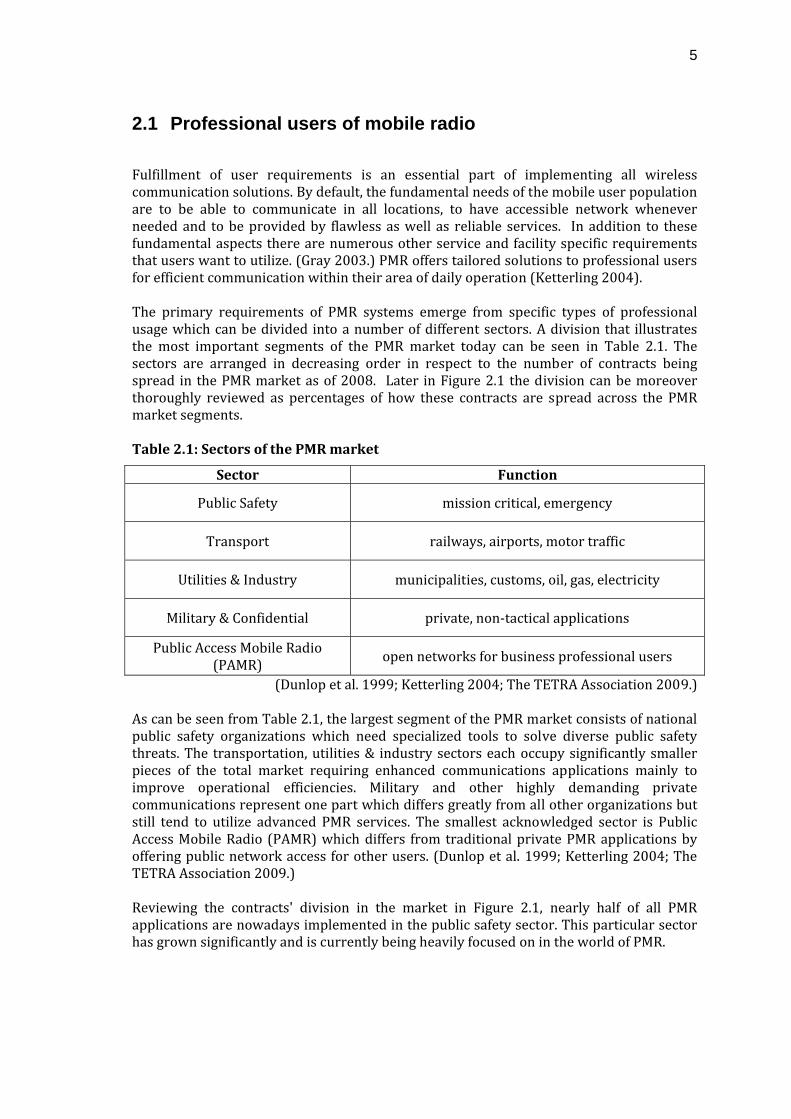
Fulfillment of user requirements is an essential part of implementing all wireless communication solutions. By default, the fundamental needs of the mobile user population are to be able to communicate in all locations, to have accessible network whenever needed and to be provided by flawless as well as reliable services. In addition to these fundamental aspects there are numerous other service and facility specific requirements that users want to utilize. (Gray 2003.) PMR offers tailored solutions to professional users for efficient communication within their area of daily operation (Ketterling 2004). The primary requirements of PMR systems emerge from specific types of professional usage which can be divided into a number of different sectors. A division that illustrates the most important segments of the PMR market today can be seen in Table 2.1. The sectors are arranged in decreasing order in respect to the number of contracts being spread in the PMR market as of 2008. Later in Figure 2.1 the division can be moreover thoroughly reviewed as percentages of how these contracts are spread across the PMR market segments. Table 2.1: Sectors of the PMR market
Sector Function
Public Safety mission critical, emergency
Transport railways, airports, motor traffic
Utilities & Industry municipalities, customs, oil, gas, electricity
Military & Confidential private, non‐tactical applications
Public Access Mobile Radio (PAMR) open networks for business professional users
(Dunlop et al. 1999; Ketterling 2004; The TETRA Association 2009.) As can be seen from Table 2.1, the largest segment of the PMR market consists of national public safety organizations which need specialized tools to solve diverse public safety threats. The transportation, utilities & industry sectors each occupy significantly smaller pieces of the total market requiring enhanced communications applications mainly to improve operational efficiencies. Military and other highly demanding private communications represent one part which differs greatly from all other organizations but still tend to utilize advanced PMR services. The smallest acknowledged sector is Public Access Mobile Radio (PAMR) which differs from traditional private PMR applications by offering public network access for other users. (Dunlop et al. 1999; Ketterling 2004; The TETRA Association 2009.) Reviewing the contracts' division in the market in Figure 2.1, nearly half of all PMR applications are nowadays implemented in the public safety sector. This particular sector has grown significantly and is currently being heavily focused on in the world of PMR.
6
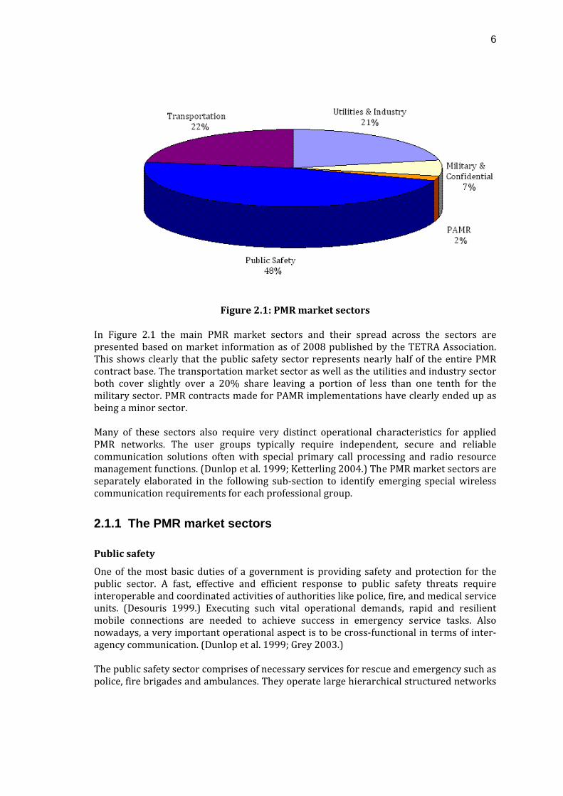
Figure 2.1: PMR market sectors
In Figure 2.1 the main PMR market sectors and their spread across the sectors are presented based on market information as of 2008 published by the TETRA Association. This shows clearly that the public safety sector represents nearly half of the entire PMR contract base. The transportation market sector as well as the utilities and industry sector both cover slightly over a 20% share leaving a portion of less than one tenth for the military sector. PMR contracts made for PAMR implementations have clearly ended up as being a minor sector. Many of these sectors also require very distinct operational characteristics for applied PMR networks. The user groups typically require independent, secure and reliable communication solutions often with special primary call processing and radio resource management functions. (Dunlop et al. 1999; Ketterling 2004.) The PMR market sectors are separately elaborated in the following sub‐section to identify emerging special wireless communication requirements for each professional group.
2.1.1 The PMR market sectors
Public safety
One of the most basic duties of a government is providing safety and protection for the public sector. A fast, effective and efficient response to public safety threats require interoperable and coordinated activities of authorities like police, fire, and medical service units. (Desouris 1999.) Executing such vital operational demands, rapid and resilient mobile connections are needed to achieve success in emergency service tasks. Also nowadays, a very important operational aspect is to be cross‐functional in terms of inter‐agency communication. (Dunlop et al. 1999; Grey 2003.) The public safety sector comprises of necessary services for rescue and emergency such as police, fire brigades and ambulances. They operate large hierarchical structured networks
7
of professionals with often nationwide coverage. (Ketterling 2004.) A current requirement for efficient public safety solutions is the availability of inter‐agency functions which is being enabled by the movement from old proprietary analog systems to modern open digital PMR standards. (DHS 2006; EADS 2006; Grey 2003.) In short, public safety users require rapid real‐time mobile communications with command, control and coordination applications across profession boundaries for information sharing during operative activities. Information shared minimizes the threat to life, health, and property and thus it is essential to provide adequate communication for personnel in the field. (Desouris 1999; DHS 2006.) Interoperability in the field of PMR networks has seen a significant change during recent years. Recently, PMR network procurement trends have started to change due to the needs and realized benefits of network sharing. In the past each organization had its own private communication system which basically originated from technological constraints set by analog PMR systems. The current trend for the public safety market is to utilize shared networks and multi‐agency support which is made possible by digitalization of the systems. Common shared infrastructure is enabled by an ability to define proper Virtual Private Networks (VPN) for each organization in such a consortium. This also provides additional benefits through division of the infrastructure and operating costs. (Gray 2003.)
Transportation
For transportation line of businesses involving airports, railways, motor traffic, etc., PMR systems represent a beneficial communication solution. Efficient voice and data communication applications are required when transport system operations are coordinated. PMR systems should be often highly customized according to the type of transportation which brings additional demands for the utilized system. The most important characteristics are optimized operational effectiveness, enhanced security and advanced services. (Dunlop et al. 1999; EADS 2009a.)
Utilities & industry
The utilities and the commercial industry fields of profession have much in common when considering wireless communications needs, and therefore, those have been combined to be covered by a single PMR market sector. The providers and operators all function on small to large network sizes and require high reliability voice and data communications. Nowadays, they might even operate with high level of collaboration with the public safety sector in the field of securing vital public utilities. (Grey 2003.) Utilities providers and various commercial industry players like oil, gas, electricity, etc., benefit from the implementation of a PMR network by gaining top quality communication, control of a network and costs, special emergency operability and useful applications (Grey 2003).
Military & confidential
Professional mobile radio is also used by the military for non‐tactical and peace keeping operations when the commercial technologies which are available meet their requirements. Also network interoperability or shared solutions with public safety professionals has multiple recognized synergies in the field of national safety. (Grey 2003.)
8
Public Access Mobile Radio (PAMR)
Parties that need to utilize the features of PMR face a choice of whether to own such a communications system or to lease it from a service provider. Public Access Mobile Radio, also known as professional cellular or public trunking, provides public PMR services available to multiple users with many different requirements while generating revenue for a network operator. This way users might gain access to larger coverage and better grade of service than with a network it would afford by its own and it need not to worry about network operations and maintenance tasks. In PAMR networks charging features are very important in addition to traditional PMR features. (Ofcom 1999.)
2.2 Features of PMR systems
For PMR systems, professional applications are the primary reason for acquisition and thus many important elements of fundamental features and operability are implemented. These key features were also listed earlier in this chapter and in this section these elements are studied further to find out why are these actually required from PMR systems.
• Radio coverage and resources
As professional mobile radio users typically are working in very diverse field environments with limited choice as to where to establish a call. Therefore, wide coverage is essential for having the possibility for mobile communication in all locations. Sufficient coverage by itself does not typically fulfill the requirements but also adequate radio resources must be provided for operational hotspots.
• Capability for data transmission
Data services are providing many important features for various daily operations of professionals using the systems. Nowadays PMR user field operations depend much on both data and voice communication. As usage and complexity of data services are constantly increasing, the pure capability for transmitting data is no longer adequate. As it turns out PMR systems needs to provide also faster data rates and system capacity.
• Reliability and quality
Any mobile radio user depends on service availability. Losing service or even the reliability that as such exists could be fatal for functioning efficiently. Especially PMR systems are used in safety critical operations where service availability is mandatory. For data applications poor reliability means discontinuous transmissions and data unreliability which might compromise the very function of a certain application.
• Pointtopoint and group calls
In addition to having two‐way communication the principle PMR requirement is to have group call functionality. This requires efficient group handling mechanisms to
9
be implemented in the utilized network. Also many data applications are designed to utilize information sharing functionalities.
• Fast call setup
Calls made in PMR systems are often very short in duration and also several calls could be originated at a very fast pace between the same parties. Therefore, terminal operations must be simplified with so called "push‐to‐talk" functionality. For gaining advantage of such terminal functionality, a network infrastructure must be able to establish connections without disrupting delay.
• Dispatch operation
Centralized dispatcher controlling and monitoring is a common implementation in many PMR systems. It is a required feature for multiple administrative operations like organization, subscriber and workstation user management. Group and subscriber management are usually daily functions which enables great benefits and efficiency to the end‐user organizations.
• Security
A usual requirement for PMR systems is a high level of security. Such secure solutions include aspects like user authentication and solid encryption methods among others.
• Prioritizing
Differentiation between users brings benefits in the forms of efficient sharing the system resources between parties requiring different levels of grade of service. Related features like pre‐emptive calls enable a more efficient emergency response concept increasing the safety of all subscribers.
• Low total cost of ownership
Total cost over the entire lifetime of the whole system is what customers aim to estimate while considering solution alternatives. The total cost of ownership includes expenditures of initial capital investments for the network infrastructure, operations and maintenance functions as well as acquisition of mobile stations. An ability to share capital investments with inter‐agency cooperation is nowadays seen as an essential feature for selection of a PMR solution.
• Network interoperability
Inter‐agency operations via VPNs within a single network are not enough if looking for an ability to roam and communicate across larger coverage areas. Such connection between multiple networks is enabled by non‐proprietary interfaces Inter System Interface (ISI) in TETRA and Inter Subsystem Interface (ISSI) in P25.
(Dunlop et al. 1999.)
10
2.2.1 Location service and dispatching
This section describes and elaborates upon the fundamental needs for location services which have become one of the most wanted features among the users in the PMR market. It does strongly relate to the basic PMR dispatching operation since keeping track of a units' geographical location provides a significant advantage for dispatchers to manage field resources efficiently. While field operations are becoming more demanding in terms of required inter‐agency operability, network interoperability and larger fleets, it is obvious that modern and more efficient methods for managing the operations are becoming essential. Therefore, any earlier PMR implementations providing just basic voice communications are becoming obsolete as new data services are becoming more and more beneficial. As a consequence a strong interest in location based services has emerged as more efficiency for various PMR operations are brought by the services of unit positioning. With such services a fleet unit management would improve significantly providing the knowledge of the location of each requested unit. Combined with other data services and fleet information this concept is also becoming a must feature for PMR users. (Desourdis et al. 2002; Gray 2003.) Communication between dispatching and field units often include information about geographical location where the operation takes place and the unit positions relative to that. Traditionally, this vital information about the areas where the units are at the certain time instant could be provided by voice communication. This status factor can be moreover enhanced with better knowledge of unit locations provided by virtually real time acquired information of unit location co‐ordinates via the LS. Various applications utilizing the location data provided are nowadays used to aid the dispatcher's decisions. (Grey 2003.) What significantly drives the demand for utilization of the positioning services are increasingly initiated requirements for the public safety sector for utilizing the services. This also shows the importance of the location knowledge in public safety field tasks and operational decision making. Various use organizations have realized the benefits for these kinds of applications and thus the services are now often included among the required feature set of planned PMR networks. (EADS 2006; DHS 2006.)
2.3 PMR technologies
The concept of PMR can be covered by multiple technologies but the ultimate choice is always made by a customer. The decision is typically affected by many factors like overall price, system references and fulfillment of various different service function requirements. In all, customer organizations are purchasing solutions which suits their operational and business needs the best. As stated previously, in most cases professional usage requires highly customized and advanced functionalities like group calling and service availability, thus limiting the attractiveness of inadequate PLMN cellular systems like GSM and UMTS. (Grey 2003.) Nowadays the primary PMR dedicated technologies are standardized TETRA and P25 as well as other proprietary PMR technologies like TETRAPOL. These three PMR specific
11
technologies are currently dominating PMR markets and are introduced in following subsections.
2.3.1 TETRA
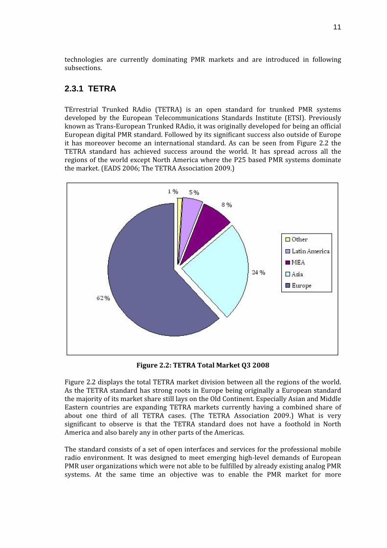
TErrestrial Trunked RAdio (TETRA) is an open standard for trunked PMR systems developed by the European Telecommunications Standards Institute (ETSI). Previously known as Trans‐European Trunked RAdio, it was originally developed for being an official European digital PMR standard. Followed by its significant success also outside of Europe it has moreover become an international standard. As can be seen from Figure 2.2 the TETRA standard has achieved success around the world. It has spread across all the regions of the world except North America where the P25 based PMR systems dominate the market. (EADS 2006; The TETRA Association 2009.)
Figure 2.2: TETRA Total Market Q3 2008
Figure 2.2 displays the total TETRA market division between all the regions of the world. As the TETRA standard has strong roots in Europe being originally a European standard the majority of its market share still lays on the Old Continent. Especially Asian and Middle Eastern countries are expanding TETRA markets currently having a combined share of about one third of all TETRA cases. (The TETRA Association 2009.) What is very significant to observe is that the TETRA standard does not have a foothold in North America and also barely any in other parts of the Americas. The standard consists of a set of open interfaces and services for the professional mobile radio environment. It was designed to meet emerging high‐level demands of European PMR user organizations which were not able to be fulfilled by already existing analog PMR systems. At the same time an objective was to enable the PMR market for more
12
competitive environment with open standardization and system level interoperability. An ability to utilize different manufacturers' equipment enables advantages like network interoperability, cost reduction by tendering and greater supply of user specific advanced applications. (Grey 2003.) As a summary, TETRA provides a multifunction tool kit from which PMR systems can be planned to satisfy professional user requirements (Ofcom 1999.). The TETRA solution is under more thorough study in this thesis since the current LS implementation is available for this platform. A more thorough of about the TETRA standard and practical implementations are discussed in Chapter 3.
2.3.2 Project 25 (P25)
Project 25 (P25), also known as APCO25, is a standardized digital radio communication system for public safety developed by the Association of Public Safety Organization Officials (APCO) jointly with the federal, state, and local governments of Northern America. It is primarily used by public safety agencies in the United States and in Canada and thus fills the same role as the European TETRA system, even with the two not being interoperable. (Ketterling 2004; P25TIG 2009.) The objectives of P25 are very much similar to those of the TETRA standard but still there are differences. The objectives of P25 are listed below
Project 25 objectives:
• Ensure competition in system life‐time procurement through open system architecture
• Allow effective, efficient and reliable communication
• Provide enhanced functionality and capabilities with a focus on public safety needs
• Improve radio spectrum efficiency
(DE 2004; Desourdis et al. 2002.) The P25 is a public LMR standard more driven by the user community needs in contrast to the initiative coming from manufacturers and operators in the case on TETRA (Desourdis et al. 2002; Dunlop et al. 1999). Resulting from this, the major differences seen between the two PMR systems are described in Table 2.2. In the USA market, it has been decided not to insist on the P25 system, but to let the market decide the more favorable technology (Desourdis et al. 2002; Dunlop et al. 1999). Still, so far the TETRA standard is not adopted as a standard in North America and thus the P25 can be considered as a national interoperability standard.
13
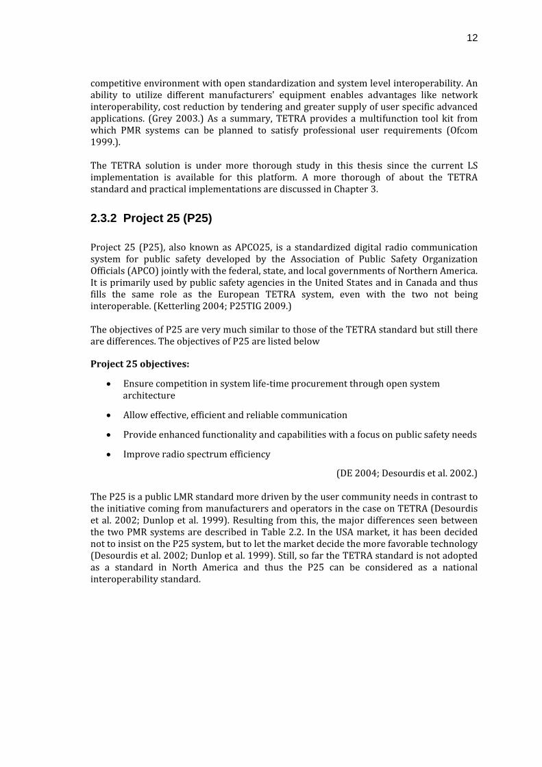
Table 2.2: PMR system implementation: P25 vs TETRA
P25 TETRA
For US public safety users For many end‐user types
For few users in wide area For high traffic loads
Optimized for non‐trunking Trunking
Kept simple for low costs Competition keeps costs low
In Table 2.2 the major differences between P25 and TETRA systems are presented. The root cause for such a different approach between the two standards is that P25 is specifically designed for public safety usage while TETRA is for various different user groups. The result of such a comparison clearly suggest that the TETRA standard is also designed for much larger PMR systems in terms of usage rate and on application diversity. (DE 2004; DHS 2006; The TETRA Association 2009.)
2.3.3 TETRAPOL
TETRAPOL has been for a long time the main competitor to TETRA in Europe mainly because it serves the same PMR market domain and had a significant advantage by being available a few years before TETRA. It is a proprietary digital PMR system developed for public safety in France and further also taken into use elsewhere in the world. Like TETRA, it is designed for a very similar PMR usage and is found to be very usable also in the utilities and industry sector. Besides the fact that TETRAPOL is a proprietary technology, the differences from TETRA can be seen while comparing technological feasibility between various system implementations in terms of size and service requirements. Additionally, TETRAPOL does not have capabilities to serve the PAMR market. (Dunlop et al. 1999; Grey 2003; Ketterling 2003.) While having a wide range of publicly available specifications a very significant drawback for TETRAPOL is that it is not formally approved by ETSI. Additionally, the TETRAPOL market is dominated by one manufacturer and thus the TETRA market might be seen more attractive for implementation of multi‐vendor technology. (Dunlop et al. 1999; Grey 2003.) The effects of these drawbacks can be seen from the fact that TETRA has achieved contract base approximately 20 times larger than TETRAPOL as of 2008. (EADS 2009a; The TETRA Association 2009.) This is an exceptionally convincing indicator that TETRA is currently the preferred technology of choice for PMR systems.
14
3 Terrestrial Trunked Radio (TETRA)
Terrestrial Trunked Radio (TETRA) is a private mobile specification standardized by the European Telecommunications Standards Institute (ETSI) during the 1990s. Even though it was originally developed for replacing outdated European analog PMR systems and to stimulate the movement towards the digital era, it is currently adopted as a truly open international digital PMR standard. TETRA is supported by an organization of manufacturers, operators and other interested parties called the TETRA Association formerly known as the TETRA MoU. Being currently used in over 100 countries worldwide and having over 2000 reported contracts it can be said that there exists a significant need for TETRA. (Grey 2003; The TETRA Association 2009.) The purpose of the ETSI TETRA standard was to develop a series of open interfaces to enable independent manufacturers to produce interoperable equipment. This was especially seen to encourage competition in the PMR market. As what comes to the PMR system needs, there are a lot of older communication systems that are becoming obsolete and need to be replaced soon. The main purpose of TETRA is to meet the high demands and needs of all PMR user organizations which were fully introduced in the earlier chapters. At first the obsolete systems must be replaced, and second, the substitutive system should overcome the latter in terms of offered features. Still, in the PMR community, voice is the primary form of communication while various data applications are increasingly beginning to emerge. New digital technology that TETRA provides will solve, for example, multiple security and data communication issues that are not covered sufficiently by features of the old systems. (Grey 2003; The TETRA Association.) The TETRA standard actually consists of a set of ETSI standards which are still today being developed according to user needs and priorities. As was seen in the previous chapter the largest segment of TETRA users are in the field of public security. The second largest increase in usage can be seen in transportation applications. Also what is interesting is that TETRA is also used by the military for non‐tactical operations, a market segment not originally anticipated for TETRA.
3.1 The TETRA Standard
The competitive environment has been seen to provide multiple positive effects in the telecommunications industry and is being widely recognized that the introduction of competition outweighs greatly any disadvantages (Intven et al. 2000). To nourish this aspect TETRA has been developed to be an open standard for enabling more advanced competition on the PMR market. As TETRA has been available for well over a decade, the success of creating competitive environment can be seen by studying the vast amount of entrants that have taken part and contributed to TETRA industry and system development. (The TETRA Association 2009.) As the TETRA standard is meant to be an open standard it covers a certain level of specification of the TETRA network interfaces thus leaving suitable level of creativity within the network infrastructure to manufacturers. While discussing the TETRA standard it should be mentioned that actually the standard consists of multiple separate standards.
15
These standards are also commonly separated as release packages current, the ones being TETRA Release 1 and Release 2. As mentioned, the standard is developed to enable network equipment interoperability and, therefore, the most important details rely on interfaces to the TETRA system. (Ketterling 2004; The TETRA Association 2009.) An overview of the network elements and interfaces covered by the TETRA Release 1 can be found later in this section. TETRA Release 2 involves several system enhancements seen necessary by both users and manufacturers. It mainly focuses on service level functionalities without changing the fundamental structure of standard interfaces. In addition to AI range and voice codec enhancements, an important high speed data service called TETRA Enhanced Data Service (TEDS) was introduced. (The TETRA Association 2009.)
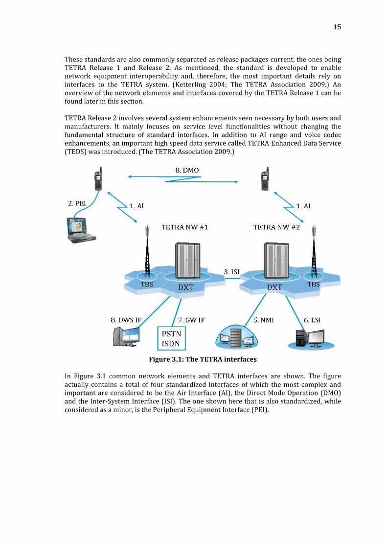
Figure 3.1: The TETRA interfaces
In Figure 3.1 common network elements and TETRA interfaces are shown. The figure actually contains a total of four standardized interfaces of which the most complex and important are considered to be the Air Interface (AI), the Direct Mode Operation (DMO) and the Inter‐System Interface (ISI). The one shown here that is also standardized, while considered as a minor, is the Peripheral Equipment Interface (PEI).
16
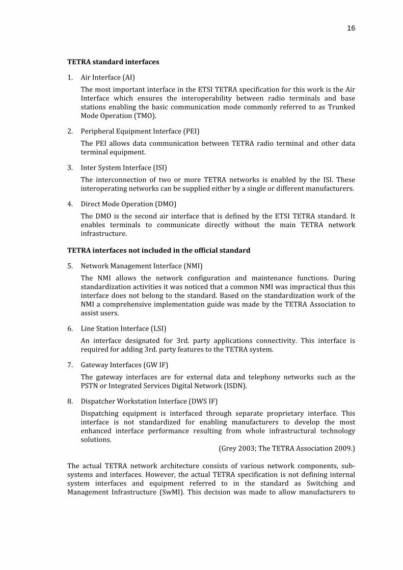
TETRA standard interfaces
1. Air Interface (AI) The most important interface in the ETSI TETRA specification for this work is the Air Interface which ensures the interoperability between radio terminals and base stations enabling the basic communication mode commonly referred to as Trunked Mode Operation (TMO).
2. Peripheral Equipment Interface (PEI) The PEI allows data communication between TETRA radio terminal and other data terminal equipment.
3. Inter System Interface (ISI) The interconnection of two or more TETRA networks is enabled by the ISI. These interoperating networks can be supplied either by a single or different manufacturers.
4. Direct Mode Operation (DMO) The DMO is the second air interface that is defined by the ETSI TETRA standard. It enables terminals to communicate directly without the main TETRA network infrastructure.
TETRA interfaces not included in the official standard
5. Network Management Interface (NMI) The NMI allows the network configuration and maintenance functions. During standardization activities it was noticed that a common NMI was impractical thus this interface does not belong to the standard. Based on the standardization work of the NMI a comprehensive implementation guide was made by the TETRA Association to assist users.
6. Line Station Interface (LSI) An interface designated for 3rd. party applications connectivity. This interface is required for adding 3rd. party features to the TETRA system.
7. Gateway Interfaces (GW IF) The gateway interfaces are for external data and telephony networks such as the PSTN or Integrated Services Digital Network (ISDN).
8. Dispatcher Workstation Interface (DWS IF) Dispatching equipment is interfaced through separate proprietary interface. This interface is not standardized for enabling manufacturers to develop the most enhanced interface performance resulting from whole infrastructural technology solutions.
(Grey 2003; The TETRA Association 2009.) The actual TETRA network architecture consists of various network components, sub‐systems and interfaces. However, the actual TETRA specification is not defining internal system interfaces and equipment referred to in the standard as Switching and Management Infrastructure (SwMI). This decision was made to allow manufacturers to
17
implement as effective solutions as possible without constraints arising from standardization. (Dunlop et al. 1999; The TETRA Association 2009.) The level of development freedom means in principle that any given TETRA infrastructure should function with TETRA mobile stations made by any manufacturer. To support this principle, the TETRA product certification process is established by the TETRA Association providing testing and interoperability certification. (The TETRA Association 2009.)
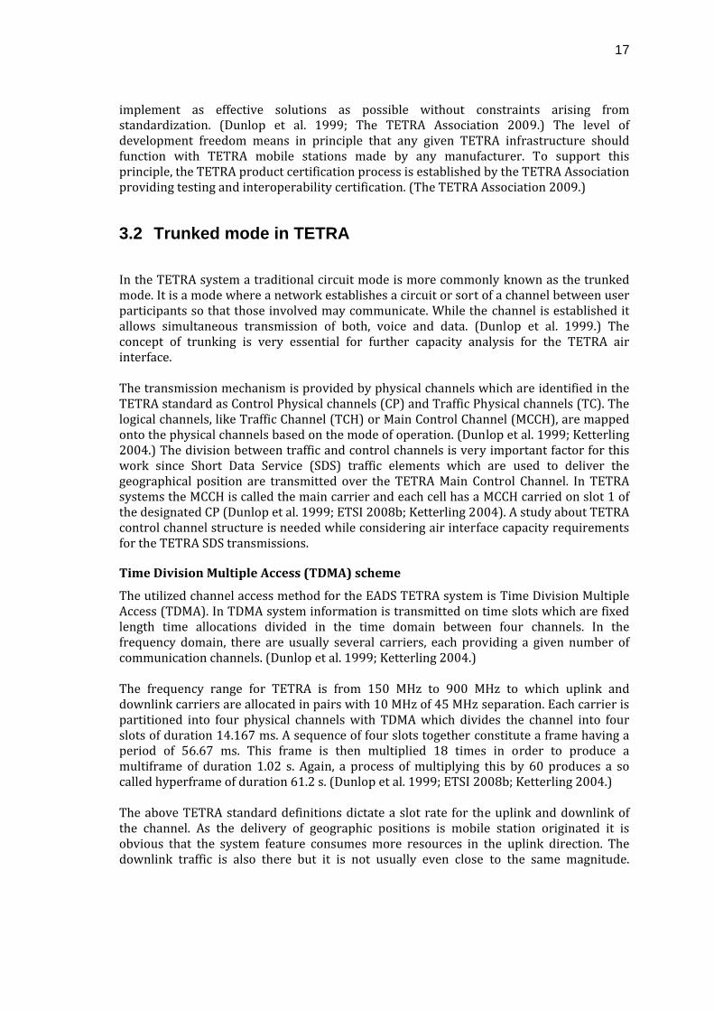
3.2 Trunked mode in TETRA
In the TETRA system a traditional circuit mode is more commonly known as the trunked mode. It is a mode where a network establishes a circuit or sort of a channel between user participants so that those involved may communicate. While the channel is established it allows simultaneous transmission of both, voice and data. (Dunlop et al. 1999.) The concept of trunking is very essential for further capacity analysis for the TETRA air interface. The transmission mechanism is provided by physical channels which are identified in the TETRA standard as Control Physical channels (CP) and Traffic Physical channels (TC). The logical channels, like Traffic Channel (TCH) or Main Control Channel (MCCH), are mapped onto the physical channels based on the mode of operation. (Dunlop et al. 1999; Ketterling 2004.) The division between traffic and control channels is very important factor for this work since Short Data Service (SDS) traffic elements which are used to deliver the geographical position are transmitted over the TETRA Main Control Channel. In TETRA systems the MCCH is called the main carrier and each cell has a MCCH carried on slot 1 of the designated CP (Dunlop et al. 1999; ETSI 2008b; Ketterling 2004). A study about TETRA control channel structure is needed while considering air interface capacity requirements for the TETRA SDS transmissions.
Time Division Multiple Access (TDMA) scheme
The utilized channel access method for the EADS TETRA system is Time Division Multiple Access (TDMA). In TDMA system information is transmitted on time slots which are fixed length time allocations divided in the time domain between four channels. In the frequency domain, there are usually several carriers, each providing a given number of communication channels. (Dunlop et al. 1999; Ketterling 2004.) The frequency range for TETRA is from 150 MHz to 900 MHz to which uplink and downlink carriers are allocated in pairs with 10 MHz of 45 MHz separation. Each carrier is partitioned into four physical channels with TDMA which divides the channel into four slots of duration 14.167 ms. A sequence of four slots together constitute a frame having a period of 56.67 ms. This frame is then multiplied 18 times in order to produce a multiframe of duration 1.02 s. Again, a process of multiplying this by 60 produces a so called hyperframe of duration 61.2 s. (Dunlop et al. 1999; ETSI 2008b; Ketterling 2004.) The above TETRA standard definitions dictate a slot rate for the uplink and downlink of the channel. As the delivery of geographic positions is mobile station originated it is obvious that the system feature consumes more resources in the uplink direction. The downlink traffic is also there but it is not usually even close to the same magnitude.
18
Therefore, the analysis about MCCH capacity is only made for the uplink direction to help with the further location traffic analysis. The uplink MCCH capacity can be derived from the fact that one carrier per cell is devoted to carry MCCH traffic. For TETRA uplink the TDMA scheme naturally offers also four time slots per frame. This means that in normal operation the first time slot of every frame is allocated for control purposes. In short, every uplink frame has exactly one CP and three TPs. (Dunlop et al. 1999; ETSI 2008b; Ketterling 2004.) As MCCH is utilizing one slot per frame it acquires roughly 18 slots per second for its use. To be exact in EADS TETRA systems one half‐slot of every fourth multiframe is consumed for other purposes. This means an average uplink capacity of 35.5 available half‐slot random access possibilities for mobile station use per second.
3.3 EADS TETRA infrastructure
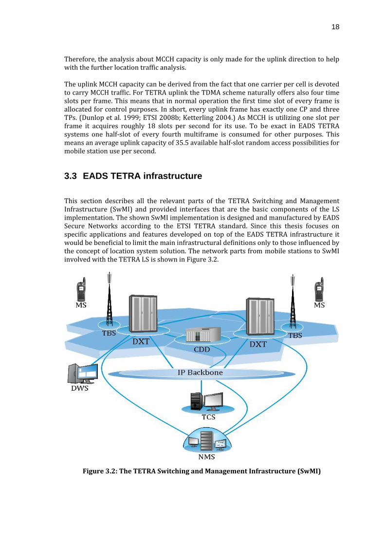
This section describes all the relevant parts of the TETRA Switching and Management Infrastructure (SwMI) and provided interfaces that are the basic components of the LS implementation. The shown SwMI implementation is designed and manufactured by EADS Secure Networks according to the ETSI TETRA standard. Since this thesis focuses on specific applications and features developed on top of the EADS TETRA infrastructure it would be beneficial to limit the main infrastructural definitions only to those influenced by the concept of location system solution. The network parts from mobile stations to SwMI involved with the TETRA LS is shown in Figure 3.2.
Figure 3.2: The TETRA Switching and Management Infrastructure (SwMI)
19
Figure 3.2 shows the EADS TETRA SwMI involved with the TETRA LS solution. The included elements, with the exception of DWS and NMS, handle the location update data delivery between MSs and TCS. The TCS is the network element which provides TETRA system connectivity interface for the LS subsystem. For the LS, the DWS element takes part in subscriber management as NMS deals with network management and supervision tasks. (EADS 2009a; EADS 2009b.)
MS – Mobile Station
MS equipment represents the users' tools for wireless voice and data communication via a TETRA network. TETRA mobile stations can be categorized in terms of equipment portability as hand‐portable or vehicle‐mounted models which both fulfill the same basic functions. For the TETRA LS a MS is a user equipment that acquires the geographical coordinates via the Global Positioning System (GPS) and transmits these through the TETRA AI.
TBS – TETRA Base Station
TETRA Base Stations provide a wireless interface for TETRA networks utilizing the TETRA AI. Being a cellular system, TETRA networks' geographical coverage is provided by TBSs as cells. The TBS transmission functions are supervision, parameterization, control and air interface signaling.
DXT – Digital Exchange for TETRA
The DXT is an access‐layer switch which is the center of all communications supporting fast call set‐up and high traffic throughput. It is a switching element handling all switching and management tasks required for connectivity to all other TETRA network elements. There can be multiple DXS switches implemented in one network providing and ensuring sufficient network performance.
CDD – Configuration and Data Distribution server
In the EADS TETRA system configuration, an element called the Configuration and Data Distribution (CDD) server provides a range of data distribution services. It is a mandatory network element in all multi‐DXT EADS TETRA network configurations. It provides access to all data in a network and also various services for monitoring subscribers.
TCS – TETRA Connectivity Server
The TETRA Connectivity Server (TCS) offers for authorized TCS client applications an interface to the EADS TETRA system. To enable this it provides a secure and efficient Application Programming Interface (API) for the client applications to access the services provided by the TETRA system. Such client applications include control room applications and a vast amount of 3rd party applications which are needed to extend the TETRA system feature portfolio for end‐user specific needs. One of the TCS client applications is a network element called the location server which is described in more detail in Chapter 4.
DWS – Dispatcher Workstation
Dispatching workstations are used to run PMR operations in public safety and security organizations with an effective system of fleet management and filed unit dispatching. It can also be used as a centralized location to handle subscriber and workstation user management functions.
20
NMS – Network Management System
The NMS is an optional component for TETRA. It typically enables centralized network management functions by allowing the entire network to be monitored from a single location.
(EADS 2009a; EADS 2009b.)
3.4 TETRA data services
In modern TETRA PMR systems, utilization of data communication is greatly increasing while voice remains the primary form of communication. The main driver for increasing the use of data applications is to improve productivity, operational efficiency and cost effectiveness. Also the data communication services are often designed so that spectrum utilization is improved without degradation of other services bringing also benefits to network operators. (Grey 2000.) Several data transport services have been defined by the TETRA standard, these being: Short Data Service (SDS), Packet Data Service, Multi‐Slot Packet Data Service, and High Speed Data. The most common applications relate to control room management, mobile data, telemetry, mapping, imaging, billing, location, and many more. (Grey 2000.) Current implementations for the TETRA location services are commonly utilizing the SDS messaging service which is why this service is focused on in this thesis.
Short Data Service
The TETRA standard specifies the Short Data Service (SDS) which enables a point‐to‐point and point‐to‐multipoint communication capability by short message transmissions. The messages are divided into SDS types 1‐4 which in turn are categorized in terms of data quantity accordingly from 16 bits up to 2039 bits. The lengths of SDS‐1, SDS‐2 and SDS‐3 are specified in the TETRA standard to 16bits, 32bits and 64 bits respectively. (ETSI 2008b.) An important factor for this thesis is the data carrying capacity of SDS type 4 what is user definable with the maximum of 2039 bits to be used for user defined short message services. The SDS bearer service provides reliable delivery of user defined data over the AI and can be thus utilized effectively for location service data transportation. (ETSI 2008a; ETSI 2008b.) The bearer service provided by the SDS ensures reliable delivery of data over the TETRA AI. To ensure application level inter‐operability while using SDS messages additional header information must be implemented to support the SDS Transport Layer (SDS‐TL) data transfer service. (ETSI 2008b.)
Packet Data Service
TETRA provides IP packet data possibilities in a similar way to GSM. A single slot can provide a data bearer service of 7.2 kbit/s for packet data use. This gross bit rate gives a net bit rate of 2.4 – 4.8 kbit/s depending on a utilized level of protection. This is sufficient for services like Wireless Application Protocol (WAP), e‐mail and compressed images or even slow‐speed video. (Dunlop et al. 1999; Grey 2000.)
21
MultiSlot Packet Data
TETRA can also support data transmissions up to a gross rate of 28.8 kbit/s. The resulting net bit rate after implementing data protection is from 9.6 kbit/s to 19.2 kbit/s. This transmission rate is enabled by using a maximum of four time slots for data transmission. The ability to support even higher rates enables TETRA usage of multiple other more demanding applications. (Grey 2000.)
High Speed Data
To enable more data throughput over TETRA networks requires a trade‐off between higher data rates and increased frequency spectrum use. For making this possibility available to user organizations, the TEDS standard is being implemented. It is planned to include a variety of data rates in 25 kHz, 50 kHz, 100 kHz and 150 kHz channel bandwidths. (Grey 2000.)

22
4 Location system solution in TETRA
During the past few years location services have almost become a mandatory feature for worldwide TETRA systems. The exact year when the PMR customers' demands for various location services started to emerge is hard to identify, but those surely have existed for quite some time. Significant growth of TETRA system implementations is a very obvious reason for witnessing such emergence of demand for more efficient communication and operational procedures. In PMR, and more especially in public safety and transportation, knowledge of more accurate field unit position can bring huge benefits for operations and operative efficiency. In this section, provision of location data particularly in a TETRA system is considered. Introduction of new services and features utilizing data transmissions bring about certain capacity constraints in any wireless network. In this respect, TETRA is no different and thus the capacity impact of the LS is to be studied in this thesis. To achieve this certain characteristics of location update data must be identified in terms of required capacity which is specified later on in Chapter 5. In short, a typical approach is that a geographical position of each field unit is updated with some specific frequency that serves the purpose of getting the units' fresh position to its requestor. This means that amount of resulting location update traffic increases when position information of several units is requested by multiple data end‐users. Since a possibility for receiving location information has interested PMR user organizations already for some time now, there have been a corresponding market available for location solutions. Multiple application manufacturers have grasped this opportunity and various solutions utilizing proprietary technologies are currently implemented for TETRA system via the standardized TETRA interfaces. Implementation of these 3rd. party solutions in larger networks has brought up major performance complications with limited TETRA network traffic capacity. The difficulties are mainly caused by poor solution design principles and various proprietary network elements' cumulative impacts. The focus has been just to provide services without taking increased traffic capacity and the consequences of that extra congestion into account. Lacking solution controllability, these solutions are nowadays seen as a threat to the TETRA infrastructure. Having a large amount of mobile stations with a short average location update interval in a network can cause serious trouble not only to the application utilizing the generated data but also to other fundamental TETRA network features like voice calls. This concern originates from the fact that in a TETRA system all non‐prioritized features compete for the same system resources. Especially in cases with larger networks this fact clearly identifies a need for network operators to be able to control the generated traffic. The only way to take the necessary control is to define a centralized point for location data in the network instead of implementing multiple distributed proprietary solutions. This leads to the Location System (LS) concept that is introduced in the EADS TETRA portfolio which collects and handles properly all location data in one dedicated point in a network to manage the generated location update traffic. The EADS TETRA LS enables many MS tracking features by combining multiple positioning techniques, Geographic Information Systems (GIS), wireless communications, mobile stations, and other modern information technologies. (EADS 2009b.)
23
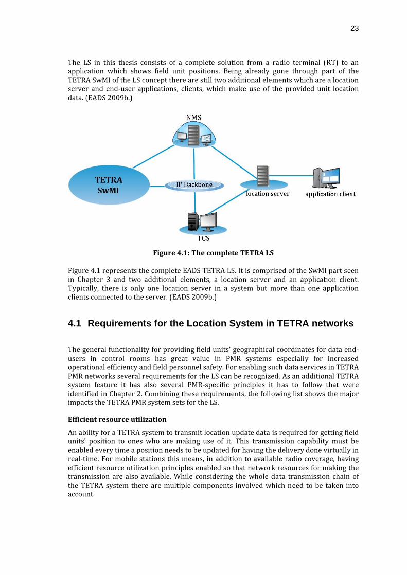
The LS in this thesis consists of a complete solution from a radio terminal (RT) to an application which shows field unit positions. Being already gone through part of the TETRA SwMI of the LS concept there are still two additional elements which are a location server and end‐user applications, clients, which make use of the provided unit location data. (EADS 2009b.)
Figure 4.1: The complete TETRA LS
Figure 4.1 represents the complete EADS TETRA LS. It is comprised of the SwMI part seen in Chapter 3 and two additional elements, a location server and an application client. Typically, there is only one location server in a system but more than one application clients connected to the server. (EADS 2009b.)
4.1 Requirements for the Location System in TETRA networks
The general functionality for providing field units' geographical coordinates for data end‐users in control rooms has great value in PMR systems especially for increased operational efficiency and field personnel safety. For enabling such data services in TETRA PMR networks several requirements for the LS can be recognized. As an additional TETRA system feature it has also several PMR‐specific principles it has to follow that were identified in Chapter 2. Combining these requirements, the following list shows the major impacts the TETRA PMR system sets for the LS.
Efficient resource utilization
An ability for a TETRA system to transmit location update data is required for getting field units' position to ones who are making use of it. This transmission capability must be enabled every time a position needs to be updated for having the delivery done virtually in real‐time. For mobile stations this means, in addition to available radio coverage, having efficient resource utilization principles enabled so that network resources for making the transmission are also available. While considering the whole data transmission chain of the TETRA system there are multiple components involved which need to be taken into account.
24
As end‐users are setting location update demands for the system according to their varying needs, limited system resources should be managed efficiently. This means that system designers should have extensive knowledge of the system and how to design it so that it functions well. These limitations nominate the maximum traffic resource availability thus having a heavy impact on location system utilization since its tendency to create large amounts of traffic. The location server is introduced to the TETRA network to provide system designers and network operators additional tools for setting limitations to the generated location update traffic.
Location system reliability
One of the PMR system requirements originates from its common usage in safety critical operations where service availability is mandatory and this requirement affects the LS as well. PMR end‐users who make use of such services need to be able to work with a reliably functioning system which delivers reliable data for use.
Support dispatch operation
As was highlighted earlier, it would be hard to imagine PMR organizations to run their operations properly without effective systems for fleet management and dispatching. The location services are specifically designated to support these activities. A dispatcher needs to be able to receive the data with an application client that is part of the LS and also to display the data graphically. A client application's interface to the location server must be proper for fulfilling the requirements set for the whole TETRA system. Also applications utilizing the interface should behave correctly so that the system is able to serve the user needs at the same time as the above requirements are met.
Multiagency interoperability
Following the basic TETRA system principles the LS has also a requirement to serve multiple different user organizations if a network is being shared. This means that private data should be isolated from the mass and that an authorized user could access the necessary data even if it does belong to multiple organizations. For location server implementation this means that it should be done so that there is no need for separate systems for each agency.
Traffic prioritization
Since TETRA is commonly used as a multi‐agency PMR system it faces many different demands from different kinds of user groups. This fact also affects location systems since fleet managers and dispatchers of each organization might require different level of service. The traffic prioritization is, in a way, a sub‐requirement for principles and tools needed for efficient system resource utilization done by network operators or system designers. Tools for setting organization specific service levels inside a location system should be implemented because the system cannot necessarily support the highest service level for each organization. There should also be an ability to prioritize location data traffic with other traffic in the TETRA network in case there are strict capacity limitations especially to prevent network exhaustion and to conserve transmission capacity.
(EADS 2009b.)
25
4.2 The location server
For implementing proper and sustainable location features to the EADS TETRA system an additional network element is needed for providing location information from the network to the control room operators and dispatchers (EADS 2009b). For this purpose a location server is presented in this section. The server completes the EADS TETRA system with efficient location features and related traffic as well as network management functionalities. The location server can be described in short as an automated location information mediation solution. It acts as a centralized point which collects and distributes all location data traffic in the network enabling geographical tracking of mobile stations in a TETRA network as an integrated system of various modern information technologies. An ability to control the location traffic requires means to control mobile stations that are the main source for the traffic. The traffic controlling functionalities are one of the primary reasons the location server is designed for. By using functionalities of the server, the LS enables more efficient resource allocation and management of location data traffic in the network. (EADS 2009b.) The actual solution for distributing and managing location update information is based on a server – client topology. This means that also additional end‐user applications, hereafter referred to also as application clients, which are utilizing the provided data are needed. While the location server is centralized the solution can be used by many different user groups independent of each other as a shared resource. The location server also has means to support a vast amount of client applications each having a possibility for differing service requirements. With the centralized server the EADS TETRA system resources can be allocated to the most appropriate utilizing party available at each time instance. This way the provided location feature will not excessively consume network resources. (EADS 2009b.) A location server should provide reliable services simultaneously for numerous mobile stations and application clients. Being modular system it should also enable usage with different wireless communications networks, hardware, client applications, and mobile stations. In summarizing, the LS should meet customers' requirement specifications and be easily integrated to already existing information systems. (EADS 2009b.) Provision of open interfaces is one of the main points in the TETRA standard, this is why it should also be emphasized in the location sever by providing open interfaces towards both, the mobile stations and the application clients. The location server provides an open interface towards mobile stations by utilizing the Location Information Protocol (LIP) standardized by the ETSI. For interfacing application clients the server implements an open standard called the Mobile Location Protocol (MLP) developed by the Open Mobile Alliance (OMA). These EADS TETRA LS interfaces mean that used mobile stations must comply with the ETSI LIP standard and application clients must be able to use the OMA MLP standard. (EADS 2009b.) These standardized protocols are more thoroughly presented in this section with an overview of the whole EADS TETRA location traffic chain. The LIP and MLP standards are probably the most important factors for understanding the traffic logic generated by the EADS location system. As one of the main elements of the
26
system, the location server performs message protocol transformation between the LIP standard used in the AI and the MLP standard used for client application connectivity (EADS 2009b). These standards enable the traffic controllability which is managed at TETRA network side by using the LIP control messages sent to mobile stations supporting the LIP standard (EADS 2009b). The server interfaces with the main EADS TETRA network via the TCS which is most commonly used by 3rd. party applications. Through the TCS it gains access to mobile stations in a network for making a location update request and reception. Also via the TCS API it can utilize all the necessary features offered by the TETRA network to operate properly. Also it can be reached by other TETRA network elements through this interface or a separate connection. Furthermore, the server offers an open interface for the application clients interested in the service features it provides. (EADS 2009b.)
4.3 Location system traffic types
This section is devoted to identifying different traffic types generated by the location system in the EADS TETRA domain. The main share of the additional network load generated by the LS is based on the number of location updates per second being performed in a TETRA system (EADS 2009b; ETSI 2008a). As mentioned earlier, the two application level protocols utilized for location data acquisition from mobile stations to application clients are the LIP and the MLP standards. The connective point between these protocols is the location server which processes the required transformation between the two. (EADS 2009b.) In addition to the location update traffic, there are several other message types being transported to enable LS features in a TETRA network. A rough categorization can be made for the traffic types into four different classes which represent the current LS generated traffic. (EADS 2009b; ETSI 2008a.) These categories can be found from the following:
• Location update messages
This traffic type involves the whole end‐to‐end TETRA network infrastructure to participate on location traffic transportation (EADS 2009b). The location update messages, also known as LIP update messages, are mobile station originated SDS type 4 messages with an additional SDS‐TL data transfer service implemented. The messages are used to deliver unit position information through the LS from a MS to application clients. (ETSI 2008a.) The primary information fields of a typical location update message include geographical coordinates and information about unit movement (ETSI 2008a). This specific traffic type covers clearly the largest amount of LS traffic towards the whole TETRA solution. Thus, managing the amount of this type of traffic is a very essential aspect while designing location solutions for any mobile network. (EADS 2009b.)
27
• Control messages
The control message type originates from the necessary traffic management functionality needs that the LS aims to fulfill for a TETRA network. Therefore, the sole purpose of these messages is to control the location update traffic generated by the mobile stations to the system. The tools for controlling the traffic with these messages are initiating, halting and adjusting the location update transmissions of MSs. (EADS 2009b; ETSI 2008a.)
• Tracking messages
The EADS TETRA system supports a subscriber‐tracking feature which provides various information attributes about the status of a MS. For receiving tracking information a separate tracking feature initiation request needs to be set to a DXT network element for each mobile station. The amount of feature requests and tracking data update messages significantly affects the total traffic between various network elements. (EADS 2009b.)
• Database synchronization
Database synchronization traffic is generated by requests for acquiring information about the EADS TETRA system organizational structure for the location server's internal processes. It generates a significantly lesser amount of traffic to a TETRA network infrastructure but still needs to be taken into account while implementing a location system. (EADS 2009b.)
For this thesis the location update messages are the most important ones since the sought ability for an application client to deviate from a standardized update interval has an impact only on those. The three other traffic types, thus being essential for an implementation of the whole LS, are not seen as significant for reaching the objectives for this thesis but should be borne in mind while doing further studies about the total traffic impact.
4.3.1 Application layer protocols
ETSI Location Information Protocol (LIP)
The TETRA AI standard describes the SDS‐TL enhanced SDS type 4 specification which the ETSI LIP standard utilizes as a location data bearer. The LIP standard belongs also to the TETRA standard and follows its technical restrictions by setting limits to minimum sending interval parameter values. The main targets for the LIP standard are to optimize the TETRA AI and to make various end‐user applications and terminals interoperable. (ETSI 2008a; ETSI 2008b.) There are several message types covered by the LIP standard which can be categorized to two classes according to the communication direction in a TETRA network. The LIP defines three different services for location information reporting that is uplink traffic: unsolicited, immediate, and triggered. The two latter services require service initiation procedures which are sent downlink as control messages by a service requestor. With the
28
trigger based update service the LIP enables compressed format of field unit location updates based on time and distance parameters. (ETSI 2008a.)
• LIP control messages
The main function of LIP control messages is to alter mobile stations' location update parameters and the reporting update interval of geographic position delivery according to the LIP standard. This way the control messages can be used to prevent MSs from overloading a network. Ultimately, this functionality is created to manage the LS generated traffic so that is follows prevailing network performance capabilities. Usage of the LIP control messages generate load to downlink part of the network. (ETSI 2008a.)
• LIP location update messages
The location update messages include information about mobile stations' geographical position and momentary movement. The LIP location update messages are sent by the mobile stations to a TETRA network and are uplink traffic for the TETRA AI. MSs generate the location update messages according to a prevailing configuration set by LIP control messages or initial MS parameterization. (ETSI 2008a.) These types of messages generate the majority of location system load especially on the TETRA AI also adding significant load on connections between the network elements involved (EADS 2009b; ETSI 2008a).
OMA Mobile Location Protocol (MLP)
Client applications are interfacing a location server through the Mobile Location Protocol (MLP) interface for acquisition of location information and data from the EADS TETRA system. The TETRA PMR systems are utilized by a wide range of users with various kinds of applications to whom MLP offers a technology transparent interface for getting the positions of mobile stations. (EADS 2009b; OMA 2005.)
• MLP control & location update messages
The MLP message types largely correspond to the LIP ones that a location server receives from the TETRA infrastructure. An exceptional difference is an ability to apply other non‐LIP related features to the server – client interface like user authentication. Also the specified protocol provides tools for sending several location data updates simultaneously in one package enabling more efficient location data transmission than the one specified in the LIP standard. (EADS 2009b; OMA 2005.)
4.3.2 Traffic profiles
By utilizing the tools presented in the previous sub‐section, an adjustability of location update traffic in a TETRA network can be reached to enable a more stable network environment. The modern applications demand more resources for fulfilling the more advanced system embedded features and the feasibility of providing this possibility needs to be studied.
29
In this thesis the objective is to study different service possibilities for application clients that are requesting a location update frequency below the limitations set by the standardized. Upgrading the best service level below the current standard limitations causes an immediate traffic increasing impact to the major LS components. To support the request, a requirement is to investigate feasibility of going below the standardized traffic rate limits. The current solutions, specified by the standards already introduced, bring basic possibilities for location information updating. Currently, the utilized location update traffic components are based on the standards and investigation for fitting those to a modern‐day application usage can be made. Utilization of a certain type of client application to a location system often forms specific traffic profiles according to varying end‐user requirements. These client applications are requesting for different levels of service from the TETRA network feature and, according to the combined impact, a certain amount of total network traffic is generated. The purpose of this section is to give an introduction to what are currently seen as the top application client profiles.
4.4 End-user client applications
The last element of the EADS TETRA LS to be covered is the end‐user client applications which are seen by the location server as clients. Numerous PMR operations require utilization of these applications for providing unit location information to the end‐users. Currently, the main location data usage environments are in PMR control rooms and control centers where field operations are managed from. Also some significant operational benefits can be acquired with applications for mobile command, control and navigation usage taking place in the field. These end‐user applications are software products combining various solutions and features for mobile tracking and communication types. This means that basically an innumerous amount of varying client applications can be built and included in the LS. It also means that there are as many different kinds of requirements towards the functionalities and service level of the LS. Probably the most well known application currently being linked to PMR location services is Automatic Vehicle Location (AVL) which is used for monitoring the geographical position of a fleet of vehicles. A similar service for personnel on foot is commonly known as Automatic Person Location (APL). An AVL system can be implemented as an individual solution providing view of ongoing field action or as a part of a larger system solution like a Computer Aided Dispatching (CAD) system. A CAD system is an advanced tool for end‐user organizations to control their resources and field operations in addition to the possibly included sub‐systems like call intake, event management, dispatching and alerting, reporting and provision of other operational information. Also other types of applications are becoming involved with the PMR systems. These client applications might require totally different types of location update frequencies and amount of information, for instance. As the scope of this thesis considers only the AI impacts while using the standard LIP traffic elements any alternative service requests are
30
neglected. Although the impact to the system should be studied once such applications are introduced. The end‐user applications used for mobile command, control and navigation purposes are typically enhanced, vehicle mounted, mobile station units or Peripheral Equipment Interface (PEI) enhancements with offer more advanced functionalities than the ordinary MSs. Typical utilization of such mobile applications are alarm reception and on‐field team guidance. For understanding the thesis objectives, short descriptions about the types of applications and relevant traffic profiles are needed. The application client types requesting non‐standard traffic performance should be identified to clarify the feasibility requirements for the studied system feature modification.
4.4.1 Time based applications
When attention is on position information of moving objects it sets certain functional requirements for the system. Probably the most challenging requirement is the periodical location update procedure which might be set to utilize very fast frequency at times. The requirement originates from the fact that the main information type being geographical coordinates of field units has a possibility of constant change thus the information needs to be updated constantly. Currently, the most utilized positioning application by far is an Automatic Vehicle Location (AVL) which is used to gain the knowledge of the geographical position of on‐duty field vehicles. The AVL service, as a system, determines the geographical location of a vehicle and delivers it to the requestor in case whether it is a system end‐user or just an automated application. Location services, as a concept, are commonly thought to be all about AVL services. It is, however, showing a great potential for also other kinds of automated applications and not just for field vehicle positioning and positioning of non‐moving objects. There is also a significant possibility for increasing the gained benefits by integrating the services to other closely related operational data. A typical AVL application provides the location information to the viewer or the dispatcher by showing the information via a display. A more advanced approach is to integrate an AVL solution to a Geographical Information System (GIS) to gain the additional advantage of geographical information about the field of operation through achieved synergies by adding other relevant data that is linked to the location in case. Considering the concept of such Location Systems as an implementation in any wireless environment and its meaning to the whole transmission chain, it is obvious that some capacity is required for transmitting the location data from mobile stations to client application end‐users. For the TETRA platform this does mean a constant location update procedure transmitting the latest position to the requestor.
31
4.4.2 Event based applications
These types of application clients are also interested of movements of an object but it handles the data a little differently as it is not necessarily interested in constant position updating. The usage philosophy difference is that visualization of the object position on a map is not necessarily the main function but to deliver reliable information about an incident. For example, only distance trigger based information might be used only to indicate an occurrence of object movement in addition to its change in the geographical position. The type of end usage does not necessarily afford to tolerate any gaps in the service as AVL client applications are typically able to skip the failing update. Service availability and reliability gaps might mean that some vital occurrence is missed and some operational aspects are compromised. An event based client application can also be included it the AVL system for example as a type of virtual fencing feature which triggers an event if some geographically set boundary is crossed by a moving field unit. These kinds of events might be triggered very often and thus requirements for a faster update frequency are real.
32
5 Network and client dimensioning
Now that principles are set for the needs of a Location System, the impacts on the service providing network really needs to be considered. The point of interest is radio access and resource consumption of the location update traffic in the TETRA AI. Approaching this, the total data payload being delivered through the TETRA AI per message update and also the resource consumption impacts caused by randomized access methods needs to be defined. Types of traffic should be described and analyzed in a certain level of detail to gain knowledge of standard traffic procedures while approaching standard application usage and its impacts on network capacity.
5.1 Data bearers at the Air Interface
The TETRA system supporting Voice plus Data (V + D) is investigated. As noted before, location updates are sent as SDS‐TL messages according to the LIP standard utilizing the TETRA V + D Air Interface. The focus during this section should be on the standard LS operational modes which should give us a proper indication of the resulting traffic impacts under study. This means a thorough investigation of the protocols used that are enabling the uplink transmissions in the TETRA AI. Approaching the solution, the first step is to study TETRA AI bearer services offering a technical transmission capability between two interfaces of a communication link. The services involved are covered by layers 1 to 3 of the International Standardization Organization – Open Systems Interconnection (ISO‐OSI) reference model. These layers being covered are the physical layer, the data link layer and the network layer. (Dunlop et al. 1999; Ketterling 2004.) In the ISO‐OSI reference model the used protocols have a relationship to one another as a protocol at a higher layer uses the services of the layer below it. For achieving this method of encapsulation, also known as tunneling, is used. This method means header addition to higher layer Protocol Data Units (PDU) which can be described as insertion or encapsulation of these higher layer PDUs as Service Data Units (SDU) to the constructed lower level PDUs. (ETSI 2008b; ITU 1996.) Quantity of resource consumption of a single location update message can be defined by fitting the SDS‐TL PDU to the available uplink slot capacity that is offered for data transmissions from TETRA mobile stations. (Ketterling 2004.) The Majority of the protocol structures that are identified in the standards are of a multipurpose nature which means that they are used by various different types of data traffic (EADS 2009b). While being specifically interested in SDS‐TL and LIP traffic, protocol utilization based on the standard definitions should be identified. In this section, the utilized data bearer PDU formats are identified to find out the resource consumption of additional header information for each location update message.
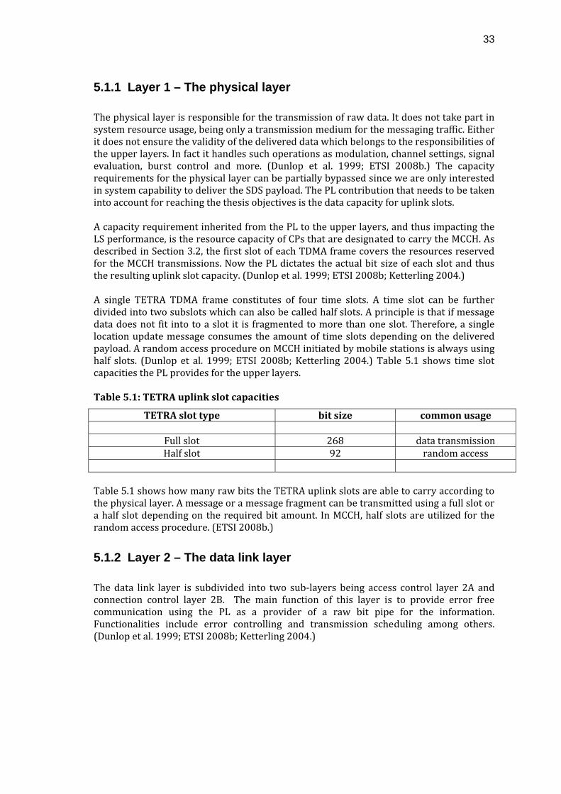
33
5.1.1 Layer 1 – The physical layer
The physical layer is responsible for the transmission of raw data. It does not take part in system resource usage, being only a transmission medium for the messaging traffic. Either it does not ensure the validity of the delivered data which belongs to the responsibilities of the upper layers. In fact it handles such operations as modulation, channel settings, signal evaluation, burst control and more. (Dunlop et al. 1999; ETSI 2008b.) The capacity requirements for the physical layer can be partially bypassed since we are only interested in system capability to deliver the SDS payload. The PL contribution that needs to be taken into account for reaching the thesis objectives is the data capacity for uplink slots. A capacity requirement inherited from the PL to the upper layers, and thus impacting the LS performance, is the resource capacity of CPs that are designated to carry the MCCH. As described in Section 3.2, the first slot of each TDMA frame covers the resources reserved for the MCCH transmissions. Now the PL dictates the actual bit size of each slot and thus the resulting uplink slot capacity. (Dunlop et al. 1999; ETSI 2008b; Ketterling 2004.) A single TETRA TDMA frame constitutes of four time slots. A time slot can be further divided into two subslots which can also be called half slots. A principle is that if message data does not fit into to a slot it is fragmented to more than one slot. Therefore, a single location update message consumes the amount of time slots depending on the delivered payload. A random access procedure on MCCH initiated by mobile stations is always using half slots. (Dunlop et al. 1999; ETSI 2008b; Ketterling 2004.) Table 5.1 shows time slot capacities the PL provides for the upper layers. Table 5.1: TETRA uplink slot capacities
TETRA slot type bit size common usage
Full slot 268 data transmission Half slot 92 random access
Table 5.1 shows how many raw bits the TETRA uplink slots are able to carry according to the physical layer. A message or a message fragment can be transmitted using a full slot or a half slot depending on the required bit amount. In MCCH, half slots are utilized for the random access procedure. (ETSI 2008b.)
5.1.2 Layer 2 – The data link layer
The data link layer is subdivided into two sub‐layers being access control layer 2A and connection control layer 2B. The main function of this layer is to provide error free communication using the PL as a provider of a raw bit pipe for the information. Functionalities include error controlling and transmission scheduling among others. (Dunlop et al. 1999; ETSI 2008b; Ketterling 2004.)
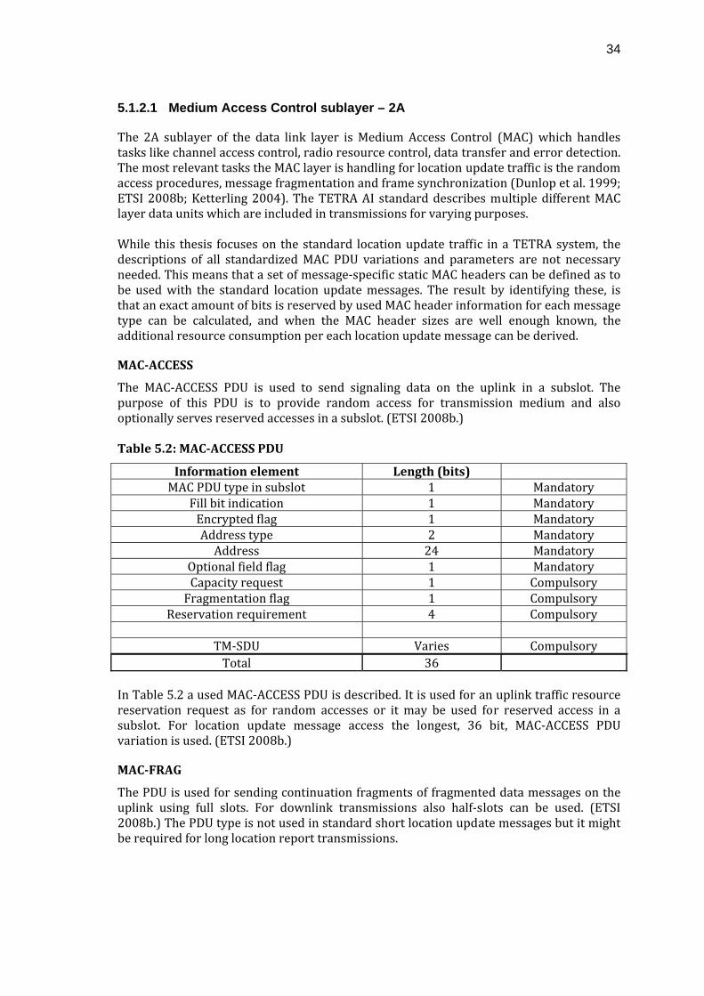
34
5.1.2.1 Medium Access Control sublayer – 2A
The 2A sublayer of the data link layer is Medium Access Control (MAC) which handles tasks like channel access control, radio resource control, data transfer and error detection. The most relevant tasks the MAC layer is handling for location update traffic is the random access procedures, message fragmentation and frame synchronization (Dunlop et al. 1999; ETSI 2008b; Ketterling 2004). The TETRA AI standard describes multiple different MAC layer data units which are included in transmissions for varying purposes. While this thesis focuses on the standard location update traffic in a TETRA system, the descriptions of all standardized MAC PDU variations and parameters are not necessary needed. This means that a set of message‐specific static MAC headers can be defined as to be used with the standard location update messages. The result by identifying these, is that an exact amount of bits is reserved by used MAC header information for each message type can be calculated, and when the MAC header sizes are well enough known, the additional resource consumption per each location update message can be derived.
MACACCESS
The MAC‐ACCESS PDU is used to send signaling data on the uplink in a subslot. The purpose of this PDU is to provide random access for transmission medium and also optionally serves reserved accesses in a subslot. (ETSI 2008b.) Table 5.2: MACACCESS PDU
Information element Length (bits) MAC PDU type in subslot 1 Mandatory
Fill bit indication 1 Mandatory Encrypted flag 1 Mandatory Address type 2 Mandatory Address 24 Mandatory
Optional field flag 1 Mandatory Capacity request 1 Compulsory Fragmentation flag 1 Compulsory
Reservation requirement 4 Compulsory
TM‐SDU Varies Compulsory Total 36
In Table 5.2 a used MAC‐ACCESS PDU is described. It is used for an uplink traffic resource reservation request as for random accesses or it may be used for reserved access in a subslot. For location update message access the longest, 36 bit, MAC‐ACCESS PDU variation is used. (ETSI 2008b.)
MACFRAG
The PDU is used for sending continuation fragments of fragmented data messages on the uplink using full slots. For downlink transmissions also half‐slots can be used. (ETSI 2008b.) The PDU type is not used in standard short location update messages but it might be required for long location report transmissions.
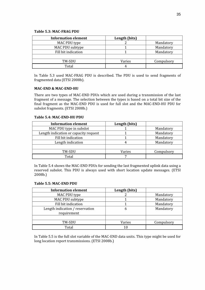
35
Table 5.3: MACFRAG PDU
Information element Length (bits) MAC PDU type 2 Mandatory
MAC PDU subtype 1 Mandatory Fill bit indication 1 Mandatory
TM‐SDU Varies Compulsory Total 4
In Table 5.3 used MAC‐FRAG PDU is described. The PDU is used to send fragments of fragmented data (ETSI 2008b).
MACEND & MACENDHU
There are two types of MAC‐END PDUs which are used during a transmission of the last fragment of a message. The selection between the types is based on a total bit size of the final fragment as the MAC‐END PDU is used for full slot and the MAC‐END‐HU PDU for subslot fragments. (ETSI 2008b.) Table 5.4: MACENDHU PDU
Information element Length (bits) MAC PDU type in subslot 1 Mandatory
Length indication or capacity request 1 Mandatory Fill bit indication 1 Mandatory Length indication 4 Mandatory
TM‐SDU Varies Compulsory Total 7
In Table 5.4 shows the MAC‐END PDUs for sending the last fragmented uplink data using a reserved subslot. This PDU is always used with short location update messages. (ETSI 2008b.) Table 5.5: MACEND PDU
Information element Length (bits) MAC PDU type 2 Mandatory
MAC PDU subtype 1 Mandatory Fill bit indication 1 Mandatory
Length indication / reservation requirement
6 Mandatory
TM‐SDU Varies Compulsory Total 10
In Table 5.5 is the full slot variable of the MAC‐END data units. This type might be used for long location report transmissions. (ETSI 2008b.)
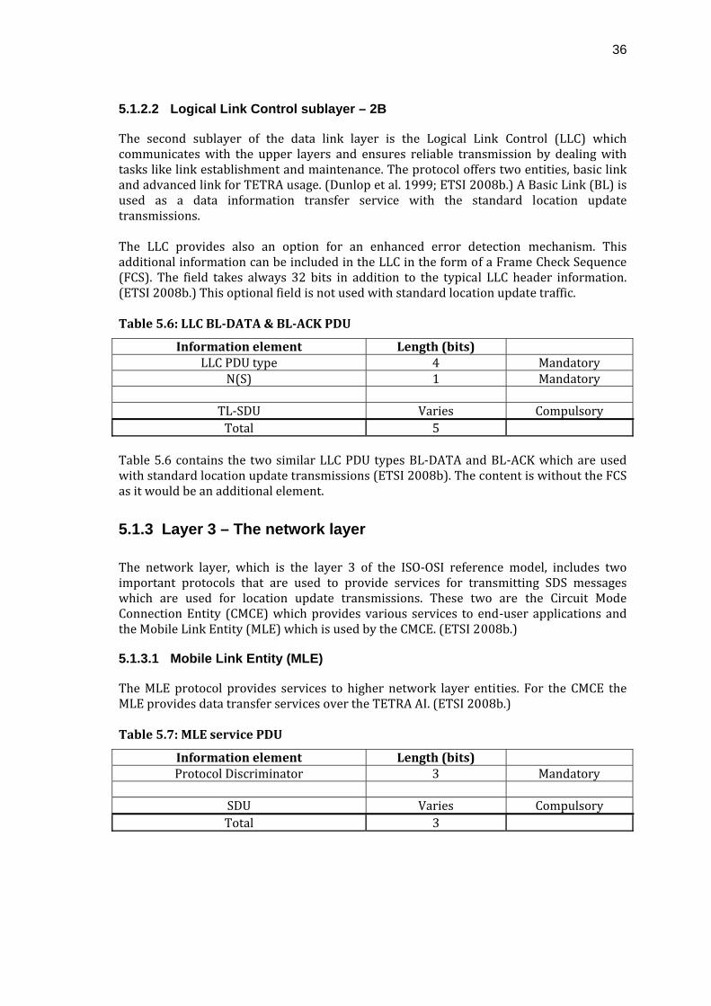
36
5.1.2.2 Logical Link Control sublayer – 2B
The second sublayer of the data link layer is the Logical Link Control (LLC) which communicates with the upper layers and ensures reliable transmission by dealing with tasks like link establishment and maintenance. The protocol offers two entities, basic link and advanced link for TETRA usage. (Dunlop et al. 1999; ETSI 2008b.) A Basic Link (BL) is used as a data information transfer service with the standard location update transmissions. The LLC provides also an option for an enhanced error detection mechanism. This additional information can be included in the LLC in the form of a Frame Check Sequence (FCS). The field takes always 32 bits in addition to the typical LLC header information. (ETSI 2008b.) This optional field is not used with standard location update traffic. Table 5.6: LLC BLDATA & BLACK PDU
Information element Length (bits) LLC PDU type 4 Mandatory
N(S) 1 Mandatory
TL‐SDU Varies Compulsory Total 5
Table 5.6 contains the two similar LLC PDU types BL‐DATA and BL‐ACK which are used with standard location update transmissions (ETSI 2008b). The content is without the FCS as it would be an additional element.
5.1.3 Layer 3 – The network layer
The network layer, which is the layer 3 of the ISO‐OSI reference model, includes two important protocols that are used to provide services for transmitting SDS messages which are used for location update transmissions. These two are the Circuit Mode Connection Entity (CMCE) which provides various services to end‐user applications and the Mobile Link Entity (MLE) which is used by the CMCE. (ETSI 2008b.)
5.1.3.1 Mobile Link Entity (MLE)
The MLE protocol provides services to higher network layer entities. For the CMCE the MLE provides data transfer services over the TETRA AI. (ETSI 2008b.) Table 5.7: MLE service PDU
Information element Length (bits) Protocol Discriminator 3 Mandatory
SDU Varies Compulsory Total 3
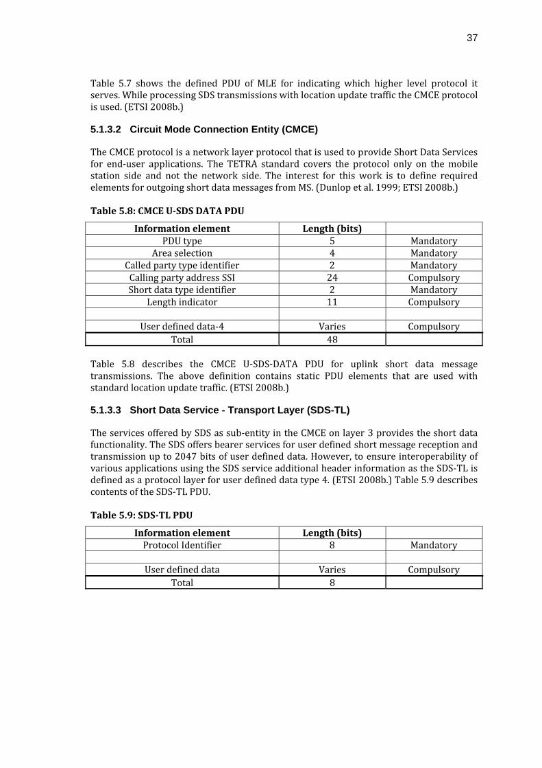
37
Table 5.7 shows the defined PDU of MLE for indicating which higher level protocol it serves. While processing SDS transmissions with location update traffic the CMCE protocol is used. (ETSI 2008b.)
5.1.3.2 Circuit Mode Connection Entity (CMCE)
The CMCE protocol is a network layer protocol that is used to provide Short Data Services for end‐user applications. The TETRA standard covers the protocol only on the mobile station side and not the network side. The interest for this work is to define required elements for outgoing short data messages from MS. (Dunlop et al. 1999; ETSI 2008b.) Table 5.8: CMCE USDS DATA PDU
Information element Length (bits) PDU type 5 Mandatory
Area selection 4 Mandatory Called party type identifier 2 Mandatory Calling party address SSI 24 Compulsory Short data type identifier 2 Mandatory
Length indicator 11 Compulsory
User defined data‐4 Varies Compulsory Total 48
Table 5.8 describes the CMCE U‐SDS‐DATA PDU for uplink short data message transmissions. The above definition contains static PDU elements that are used with standard location update traffic. (ETSI 2008b.)
5.1.3.3 Short Data Service - Transport Layer (SDS-TL)
The services offered by SDS as sub‐entity in the CMCE on layer 3 provides the short data functionality. The SDS offers bearer services for user defined short message reception and transmission up to 2047 bits of user defined data. However, to ensure interoperability of various applications using the SDS service additional header information as the SDS‐TL is defined as a protocol layer for user defined data type 4. (ETSI 2008b.) Table 5.9 describes contents of the SDS‐TL PDU. Table 5.9: SDSTL PDU
Information element Length (bits) Protocol Identifier 8 Mandatory
User defined data Varies Compulsory
Total 8
38
5.2 Location update message data payload
As mentioned on Chapter 4 there exist multiple different traffic types in a TETRA network caused by the implemented Location System. In this chapter a bit‐oriented view for the location update uplink traffic is presented as is specified in the standards and interface descriptions. The downlink part of the traffic, mainly control messaging, is not considered here. This analysis on location update message payload is the last element to be studied to be able to acquire a total message data consumption in a system. The LIP standard contains extensive selection of parameters made available for usage if only the EADS LS currently utilizes only a part of the whole. The overall parameter usage significantly affects packet size and the total resource consumption in the system. Therefore, a further division is made to short and long location reports which provide different amount of information to the data end‐user. The parameter selections of utilized reports are determined by the used LIP control messaging described in Section 4.3.1. In the EADS LS the PDU size of the short location report is static. In this work an assumption is made for reasons of simplicity that the LIP control messaging is requesting short location reports. Therefore, in this work the LIP long location report is not investigated since it is not a standard report type and exact parameter values cannot be determined.
5.2.1 Location report messages
The Location Information Protocol (LIP) is utilized in EADS TETRA LS as a being technology independent protocol which is specifically developed for TETRA air interface optimization purposes. It is specified in a sub‐part of the TETRA standard to provide an optimized protocol for the effective use of the TETRA AI by using a compact message format. In the EADS TETRA LS, the LIP is currently used for communication between the location server and mobile stations. Control messaging in a TETRA LS is typically trigger based on time or distance parameters. This approach reduces the required downlink LIP traffic as mobile stations are set to a static mode for sending updates periodically. Also immediate and unsolicited reporting schemes are enabled in the system but usage of such is not preferred in order to conserve network resources. Regardless of the service request type the reporting follows the same format.
LIP short location report message
The LIP short location report is the preferred message format to be sent as a response to a location update request in standard operational circumstances. Therefore, traffic that is generated by the EADS TETRA LS consists mainly of this message type. The basic LIP short location report PDU size is essential for network dimensioning since it determines resource consumption of a single location update.
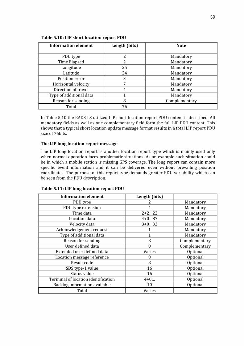
39
Table 5.10: LIP short location report PDU
Information element Length (bits) Note
PDU type 2 Mandatory Time Elapsed 2 Mandatory Longitude 25 Mandatory Latitude 24 Mandatory
Position error 3 Mandatory Horizontal velocity 7 Mandatory Direction of travel 4 Mandatory
Type of additional data 1 Mandatory Reason for sending 8 Complementary
Total 76 In Table 5.10 the EADS LS utilized LIP short location report PDU content is described. All mandatory fields as well as one complementary field form the full LIP PDU content. This shows that a typical short location update message format results in a total LIP report PDU size of 76bits.
The LIP long location report message
The LIP long location report is another location report type which is mainly used only when normal operation faces problematic situations. As an example such situation could be in which a mobile station is missing GPS coverage. The long report can contain more specific event information and it can be delivered even without prevailing position coordinates. The purpose of this report type demands greater PDU variability which can be seen from the PDU description. Table 5.11: LIP long location report PDU
Information element Length (bits) PDU type 2 Mandatory
PDU type extension 4 Mandatory Time data 2+2…22 Mandatory
Location data 4+0…87 Mandatory Velocity data 3+0…32 Mandatory
Acknowledgement request 1 Mandatory Type of additional data 1 Mandatory Reason for sending 8 Complementary User defined data 8 Complementary
Extended user defined data Varies Optional Location message reference 8 Optional
Result code 8 Optional SDS type‐1 value 16 Optional Status value 16 Optional
Terminal of location identification 4+0… Optional Backlog information available 10 Optional
Total Varies
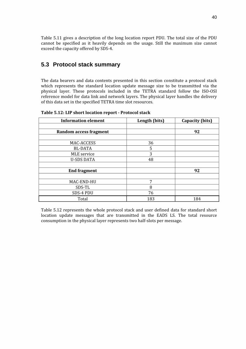
40
Table 5.11 gives a description of the long location report PDU. The total size of the PDU cannot be specified as it heavily depends on the usage. Still the maximum size cannot exceed the capacity offered by SDS‐4.
5.3 Protocol stack summary
The data bearers and data contents presented in this section constitute a protocol stack which represents the standard location update message size to be transmitted via the physical layer. These protocols included in the TETRA standard follow the ISO‐OSI reference model for data link and network layers. The physical layer handles the delivery of this data set in the specified TETRA time slot resources. Table 5.12: LIP short location report Protocol stack
Information element Length (bits) Capacity (bits)
Random access fragment 92
MAC‐ACCESS 36 BL‐DATA 5 MLE service 3 U‐SDS DATA 48
End fragment 92
MAC‐END‐HU 7
SDS‐TL 8 SDS‐4 PDU 76 Total 183 184
Table 5.12 represents the whole protocol stack and user defined data for standard short location update messages that are transmitted in the EADS LS. The total resource consumption in the physical layer represents two half‐slots per message.
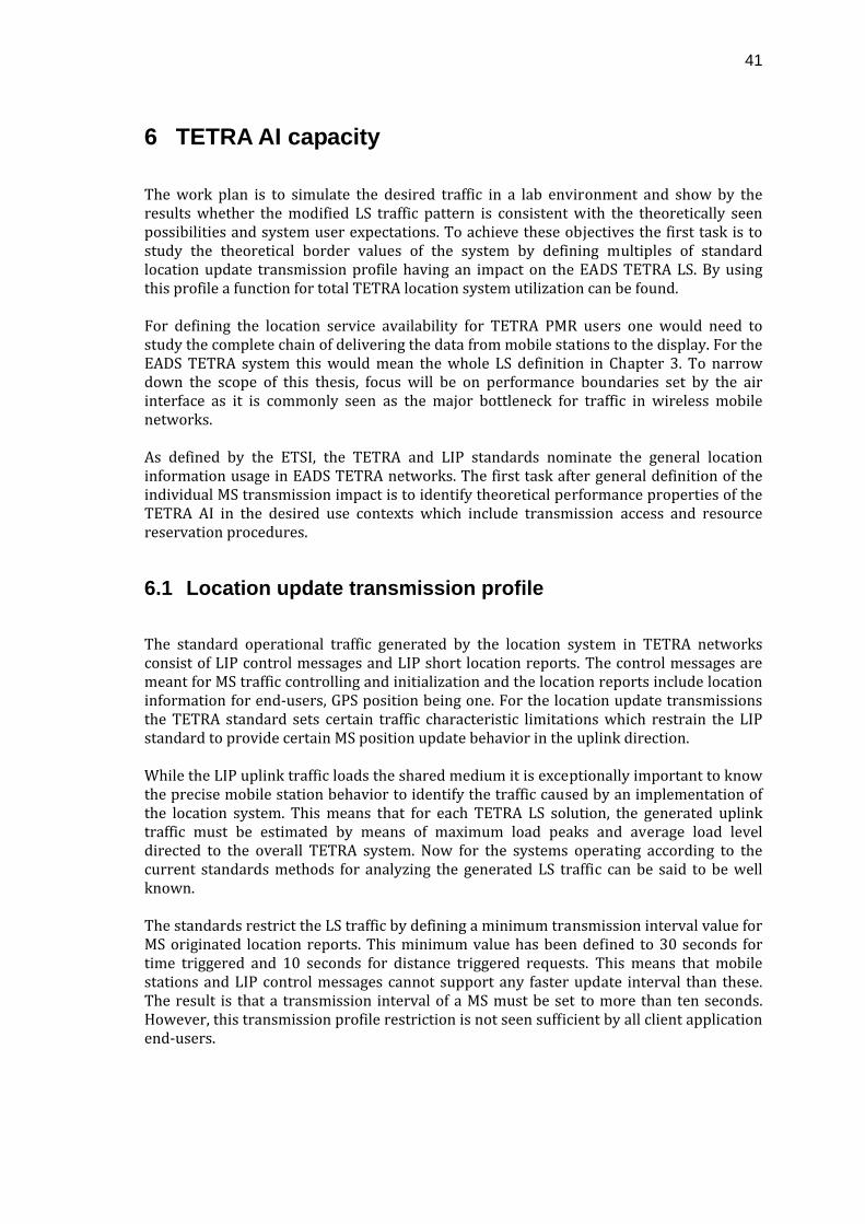
41
6 TETRA AI capacity
The work plan is to simulate the desired traffic in a lab environment and show by the results whether the modified LS traffic pattern is consistent with the theoretically seen possibilities and system user expectations. To achieve these objectives the first task is to study the theoretical border values of the system by defining multiples of standard location update transmission profile having an impact on the EADS TETRA LS. By using this profile a function for total TETRA location system utilization can be found. For defining the location service availability for TETRA PMR users one would need to study the complete chain of delivering the data from mobile stations to the display. For the EADS TETRA system this would mean the whole LS definition in Chapter 3. To narrow down the scope of this thesis, focus will be on performance boundaries set by the air interface as it is commonly seen as the major bottleneck for traffic in wireless mobile networks. As defined by the ETSI, the TETRA and LIP standards nominate the general location information usage in EADS TETRA networks. The first task after general definition of the individual MS transmission impact is to identify theoretical performance properties of the TETRA AI in the desired use contexts which include transmission access and resource reservation procedures.
6.1 Location update transmission profile
The standard operational traffic generated by the location system in TETRA networks consist of LIP control messages and LIP short location reports. The control messages are meant for MS traffic controlling and initialization and the location reports include location information for end‐users, GPS position being one. For the location update transmissions the TETRA standard sets certain traffic characteristic limitations which restrain the LIP standard to provide certain MS position update behavior in the uplink direction. While the LIP uplink traffic loads the shared medium it is exceptionally important to know the precise mobile station behavior to identify the traffic caused by an implementation of the location system. This means that for each TETRA LS solution, the generated uplink traffic must be estimated by means of maximum load peaks and average load level directed to the overall TETRA system. Now for the systems operating according to the current standards methods for analyzing the generated LS traffic can be said to be well known. The standards restrict the LS traffic by defining a minimum transmission interval value for MS originated location reports. This minimum value has been defined to 30 seconds for time triggered and 10 seconds for distance triggered requests. This means that mobile stations and LIP control messages cannot support any faster update interval than these. The result is that a transmission interval of a MS must be set to more than ten seconds. However, this transmission profile restriction is not seen sufficient by all client application end‐users.
42
To satisfy the need for a faster update interval the standard should not be followed. In practice this means modifications to MS LIP functions and the location server functionalities. As the modified LS performance requirements would not be in line with the limitations set by the standards the system impact needs to be studied. In this thesis the focus is on this location system performance enhancement request that is not supported by the present LIP standard. During this work several implementation possibilities and system impacts are analyzed based on the current system solutions for finding out feasibility for such deviation from the standards. The studied change in the system would not affect the standard MS transmission principles, thus the standard system transmission characteristics can be still used. This means an investigation of theoretical aspects of the random access and radio resource usage will be valid for characterizing also the non‐standard system. To verify the results seen during the theoretical analysis it is followed by a series of test cases to identify any aspects of system independent variables. By doing comparison between the theoretical and measurement results a non‐standard solution feasibility can be analyzed.
6.2 Random access capacity
Mobile Stations wishing to make a SDS transmission in a TETRA system are assumed to transmit their messages over a common channel called the Main Control Channel (MCCH). For initiating the data transmission access in TETRA, a protocol based on slotted ALOHA multi‐access protocol procedures are utilized. (Dunlop et al. 1999; ETSI 2008b.) In this slotted ALOHA protocol, all transmissions are synchronized so that the time axis can be divided into intervals called time slots and that a transmission may start only at the beginning of such slot. The basic principle behind the slotted ALOHA is that the transmissions can take place on a slotted medium regardless of the activity of competing terminals. While mobile stations use the random access protocol to initiate transfer to a base station, a reservation mechanism is utilized for transmitting the data that is left over from the random access slot. As described in Chapter 5, in addition to the random access half‐slot, one reserved half‐slot is needed for a complete transmission of a single short location update report. (Dunlop et al. 1999.) In slotted ALOHA, while all transmitting parties utilize the same shared medium, collisions occur whenever more than one transmission are initiated at the same time instance. A collision can thus occur between two or more simultaneously initiating transmissions typically causing loss of all data. (Dunlop et al. 1999.) After a collision all included parties whose attempt had failed are backlogged to retry mode according to the retransmission principles implemented in the TETRA random access protocol. (Dunlop et al. 1995; Sheikh 2004.) The utilized retransmission principles are furthermore presented in Section 6.2.1. A significant exception in the case of a collision is a term the called capture effect which is an event which might allow one mobile station, having the strongest signal level, to gain access regardless of the simultaneous attempts. This is a common event in radio channels with large amounts of signal level variation. The net effects of this phenomenon can be seen as an overall performance increase of a system in terms of total access probabilities,
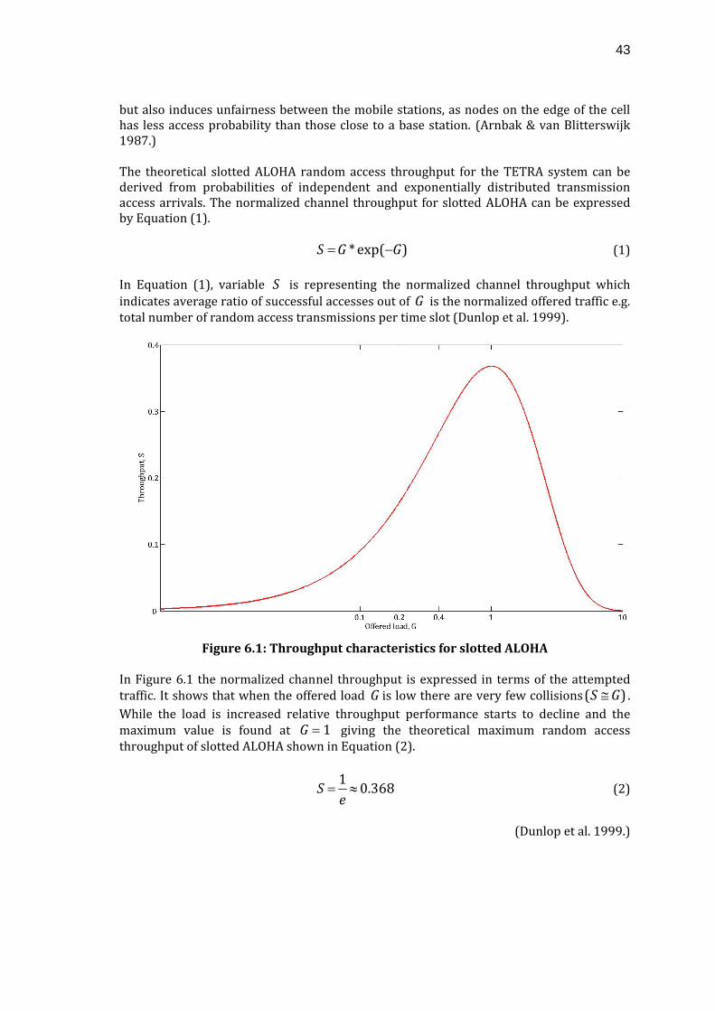
43
but also induces unfairness between the mobile stations, as nodes on the edge of the cell has less access probability than those close to a base station. (Arnbak & van Blitterswijk 1987.) The theoretical slotted ALOHA random access throughput for the TETRA system can be derived from probabilities of independent and exponentially distributed transmission access arrivals. The normalized channel throughput for slotted ALOHA can be expressed by Equation (1).
)exp(* GGS −= (1) In Equation (1), variable S is representing the normalized channel throughput which indicates average ratio of successful accesses out of G is the normalized offered traffic e.g. total number of random access transmissions per time slot (Dunlop et al. 1999).
Figure 6.1: Throughput characteristics for slotted ALOHA
In Figure 6.1 the normalized channel throughput is expressed in terms of the attempted traffic. It shows that when the offered load G is low there are very few collisions )( GS ≅ . While the load is increased relative throughput performance starts to decline and the maximum value is found at 1=G giving the theoretical maximum random access throughput of slotted ALOHA shown in Equation (2).
368.01≈=
eS (2)
(Dunlop et al. 1999.)
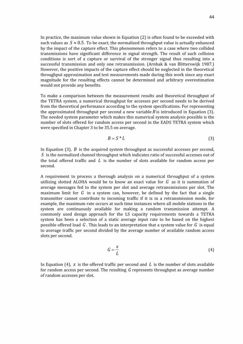
44
In practice, the maximum value shown in Equation (2) is often found to be exceeded with such values as 5.0≈S . To be exact, the normalized throughput value is actually enhanced by the impact of the capture effect. This phenomenon refers to a case where two collided transmissions have significant difference in signal strength. The result of such collision conditions is sort of a capture or survival of the stronger signal thus resulting into a successful transmission and only one retransmission. (Arnbak & van Blitterswijk 1987.) However, the positive impacts of the capture effect should be neglected in the theoretical throughput approximation and test measurements made during this work since any exact magnitude for the resulting effects cannot be determined and arbitrary overestimation would not provide any benefits. To make a comparison between the measurement results and theoretical throughput of the TETRA system, a numerical throughput for accesses per second needs to be derived from the theoretical performance according to the system specifications. For representing the approximated throughput per second a new variable B is introduced in Equation (3). The needed system parameter which makes this numerical system analysis possible is the number of slots offered for random access per second in the EADS TETRA system which were specified in Chapter 3 to be 35.5 on average.
LSB *= (3) In Equation (3), B is the acquired system throughput as successful accesses per second, S is the normalized channel throughput which indicates ratio of successful accesses out of the total offered traffic and L is the number of slots available for random access per second. A requirement to process a thorough analysis on a numerical throughput of a system utilizing slotted ALOHA would be to know an exact value for G as it is summation of average messages fed to the system per slot and average retransmissions per slot. The maximum limit for G in a system can, however, be defined by the fact that a single transmitter cannot contribute to incoming traffic if it is in a retransmission mode, for example, the maximum rate occurs at such time instances where all mobile stations in the system are continuously available for making a random transmission attempt. A commonly used design approach for the LS capacity requirements towards a TETRA system has been a selection of a static average input rate to be based on the highest possible offered load G . This leads to an interpretation that a system value for G is equal to average traffic per second divided by the average number of available random access slots per second.
Lx
G = (4)
In Equation (4), x is the offered traffic per second and L is the number of slots available for random access per second. The resulting G represents throughput as average number of random accesses per slot.
45
Figure 6.2: The slotted ALOHA throughput per second in TETRA systems
From Figure 6.2 an obtained numerical throughput can be seen for the slotted ALOHA in with the TETRA system definition of 35.5 available access slots per second. The maximum throughput of 13.059 messages per second is achieved when load to the transmission channel is 35.5 accesses per second corresponding to the offered traffic of 1=G .
6.2.1 TETRA random access protocol
The TETRA random access procedure follows the slotted ALOHA protocol but is not fully in accordance with the access mechanism. An important factor is that typically in TETRA systems the slotted ALOHA random access process and probabilities (Figure 6.1) as such are applied only for the first access tries of a transmission. This is based on a TETRA system definition that only the first access attempt is purely randomized as fresh transmissions initiate to the next available slot. For each succeeding retransmission attempt, the TETRA standard uses alternate retry method called an access framing structure. This retry method deviate the system from the standard slotted ALOHA principles as the following access attempts are not purely randomized anymore but are set to randomize over specific slots in the selected frame. (ETSI 2008b.) The advantages gained by using this method are providing the listed enhancements related to the LS generated traffic.
• controllability to the collisions of access requests
• minimized access delay and traffic loss
• maintainability of peak throughput
• avoidance of protocol instability
(ETSI 2008b.)
46
These TETRA enhancements for the slotted ALOHA mainly focus on increasing system performance with lower offered load G and reliability at higher load levels. The exact impact of these additional definitions on the theoretical approach cannot be efficiently computed since the standard does not specify the execution of the definitions but leaves majority of the decisions to TETRA equipment manufacturers. This makes the theoretical review more complicated and a thorough way for making an analysis would be to precisely model the whole system. Not having the means to do such an exact theoretical model, an approximative approach is taken in this thesis by doing the comparison with the standard slotted ALOHA. The slotted ALOHA is an unstable system by its nature and, therefore, is controlled by setting various retransmission principles so that the system could function efficiently under various load conditions. The access framing structure implemented in the TETRA random access protocol specifies access frames and system specific waiting time parameters for message retransmission use. The utilized approach means that overlapping access bursts will collide and failed ones end up initiating retransmissions which occur at a random slot in the next access frame after the system specified waiting time. (ETSI 2008b.) During this thesis it is assumed that these methods function effectively and do not negatively disturb traffic under normal stable system load conditions. Because of the modifications in the retransmission procedures, exact system parameters cannot be fully identified and an approximation must, therefore, be used in this context. In principle, the waiting time and access frame elements suggest that for each time instance there are number of terminals in a stage where they are not actually contributing to the total system load. Thus part of the mobile stations in a system do not contribute to the offered load G , an approximation to use the maximum G might result to a bit of an overestimate to the total system load while analyzing the measurement results.
6.3 LIP short location report capacity
In Table 5.12 the protocol stack for LIP short location reports that are transmitted to the uplink direction in the TETRA AI is shown. From the total bit value it can be seen that the amount of data to be transmitted via the physical layer is exactly 183bits per message. As was defined previously in Chapter 5, at the physical layer one uplink half‐slot is able to carry a MAC PDU size of 92 bits. With the included data elements a conclusion can be made that a net time slot consumption of two uplink half slots per message is required. The utilized slot reservation procedure specifies the principle behind the additional slot consumption. Following each successful random access for a short location update message a single half slot is reserved. These reserved slots are not accessible by random access transmissions. The inevitable result of this is that the available random access capacity per second for the TETRA system is reduced. In addition to this the random access collision probabilities introduce an additional resource waste according to Equation (2), which states that with peak rate system conditions only every third transmission attempt succeeds. Summing up these factors, the total resource consumption on a single LIP short location report in terms of total message size in half slots can be found from Equation (5).
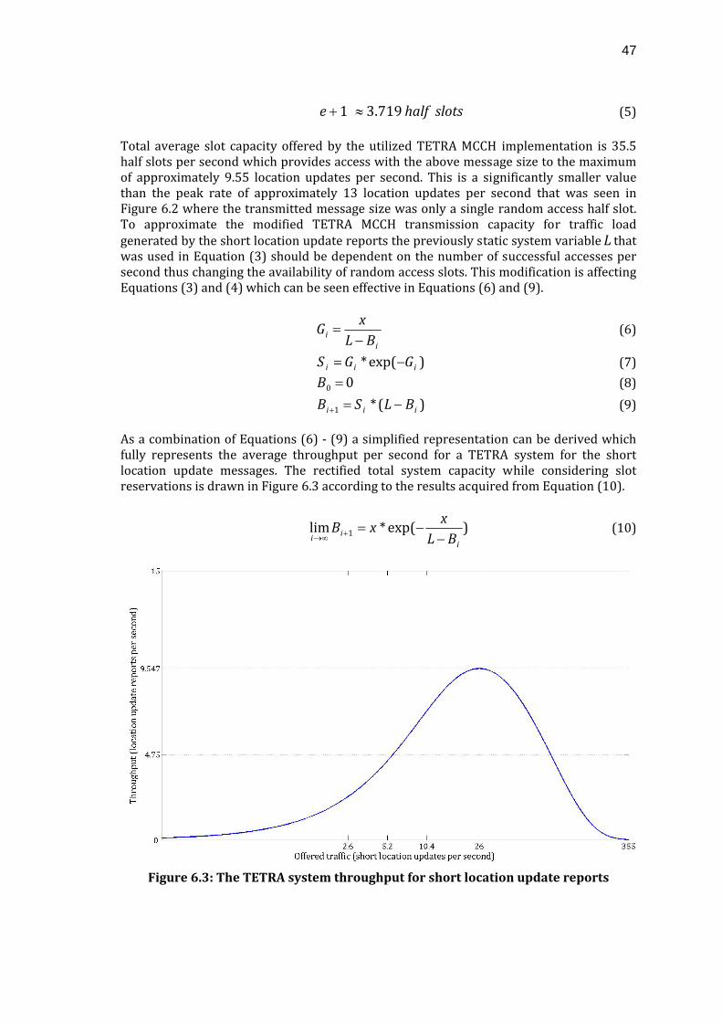
47
slotshalfe 719.31 ≈+ (5) Total average slot capacity offered by the utilized TETRA MCCH implementation is 35.5 half slots per second which provides access with the above message size to the maximum of approximately 9.55 location updates per second. This is a significantly smaller value than the peak rate of approximately 13 location updates per second that was seen in Figure 6.2 where the transmitted message size was only a single random access half slot. To approximate the modified TETRA MCCH transmission capacity for traffic load generated by the short location update reports the previously static system variable L that was used in Equation (3) should be dependent on the number of successful accesses per second thus changing the availability of random access slots. This modification is affecting Equations (3) and (4) which can be seen effective in Equations (6) and (9).
ii BL
xG
−= (6)
)exp(* iii GGS −= (7) 00 =B (8)
)(*1 iii BLSB −=+ (9) As a combination of Equations (6) ‐ (9) a simplified representation can be derived which fully represents the average throughput per second for a TETRA system for the short location update messages. The rectified total system capacity while considering slot reservations is drawn in Figure 6.3 according to the results acquired from Equation (10).
)exp(*lim 1i
ii BLx
xB−
−=+∞→ (10)
Figure 6.3: The TETRA system throughput for short location update reports
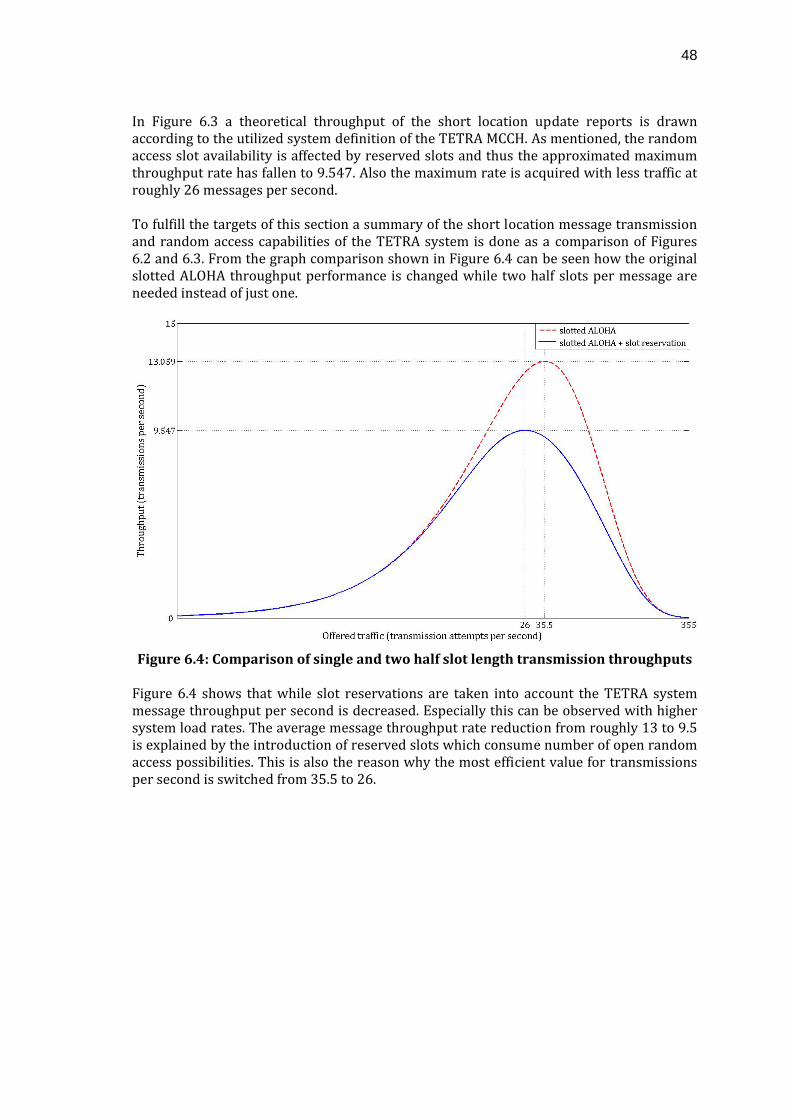
48
In Figure 6.3 a theoretical throughput of the short location update reports is drawn according to the utilized system definition of the TETRA MCCH. As mentioned, the random access slot availability is affected by reserved slots and thus the approximated maximum throughput rate has fallen to 9.547. Also the maximum rate is acquired with less traffic at roughly 26 messages per second. To fulfill the targets of this section a summary of the short location message transmission and random access capabilities of the TETRA system is done as a comparison of Figures 6.2 and 6.3. From the graph comparison shown in Figure 6.4 can be seen how the original slotted ALOHA throughput performance is changed while two half slots per message are needed instead of just one.
Figure 6.4: Comparison of single and two half slot length transmission throughputs Figure 6.4 shows that while slot reservations are taken into account the TETRA system message throughput per second is decreased. Especially this can be observed with higher system load rates. The average message throughput rate reduction from roughly 13 to 9.5 is explained by the introduction of reserved slots which consume number of open random access possibilities. This is also the reason why the most efficient value for transmissions per second is switched from 35.5 to 26.
49
7 Measurements
The current LIP standard specifies the minimum location update interval to ten seconds. The standard also defines the minimum of ten seconds to be only used with distance based triggering while the time trigger update minimum is set to 30 seconds. These update intervals are not seen to be sufficient for all application client usage, as for example, part of those that were summarized in Chapter 4. Therefore, the thesis objective is to see whether the standardized interval specifications could be neglected and what impacts would be seen in the TETRA system. To achieve this objective, test measurements are done to analyze how the LIP and TETRA standards together comply with a special mobile station behavior which could be required in some essential cases strongly related to PMR LS usage. From the measurement results can be seen what kind of service level the system can offer while deviating from the given standards. One could expect to see evidence of at least a significant growth in network resource utilization per mobile station, possibly affecting multiple aspects in a system. Two main measurement topics were separated for analysis of the Location System requirements of TETRA networks specified in Chapter 4.
• Resource utilization
While system knowledge based on the standard rules is well known by system design a study for making exceptions to system functionalities is needed to find out existing system resource limits. These limits provide valuable information for proper system utilization.
• System reliability
The reliability expectations of users of the TETRA system have an impact on all features provided for PMR users. The location system is no exception to this matter and it, therefore, needs a closer look. For the location system the reliability requirement means that is has to be able to provide continuous up‐to‐date location updates of each field unit for each end‐user requesting the data.
For studying the feasibility of increasing the LIP message update interval beyond the standardized values, test measurements provide an insight into the impacts of this system modification. In this thesis the focus is on the total system performance seen by end‐users and thus the total system end‐to‐end performance in terms of TETRA AI capabilities is measured. To pay attention to the end‐user preferences, the objective is not to identify maximum limits for pushing the standard restrictions but to find possibilities for the exceptional short‐term usage while still taking care of the fulfillment of the system requirements. From the results one would expect to find the feasibility of altering the standardized minimum interval system parameter and to make analysis of what would still be safe usage in TETRA PMR systems. The first objective of the measurements is to identify system throughput characteristics with specified levels of offered traffic per second. The achieved results would then be compared between the utilized minimum reporting interval levels as well as the theoretical throughput studied in Chapter 6. The second objective relates to one of the
50
major functionalities of the location system as being a component of the TETRA system. Concurrently with the first objective we should be able to properly manage the current traffic thus having control over the overall system resource utilization of the LS. While keeping the utilization level within sufficient boundaries it is also important to ensure minimal waste of resources in the system. In conclusion, fulfillment of this objective would mean, in fact, better resource availability for all features in the TETRA system. The test measurements were done in a real EADS TETRA environment suchlike the LS described in Chapter 3. It consisted of the simple TETRA network covering the main TETRA system elements with a single TETRA MCCH, one application client and 21 mobile stations. The test environment and system parameters were kept static between various test sessions. During the measurements message logging data of location update traffic was monitored from mobile stations to an application client. Any separate influence of individual TETRA SwMI parts were neglected as the measurement points were only at the MS and client application ends of the system. Some limitations for the test execution were caused by partially insufficient test equipment. Problems were mainly seen on the mobile station side since the total number of mobile stations did not exactly correspond to the needs for an execution of a full test set. Also the attempted deviation from the TETRA standard introduced challenges as the used mobile stations offered no means for following the intended approach. The inevitable consequence of this was the requirement for additional message feeding applications based on Java and Python that were used to transmit messages to the system. This very immature message generating method added an unwelcome extra component to the test environment which in the end could not be removed.
7.1 System throughput with modified Location System
System throughput can be measured from various parts of a network but usually the most crucial part considered as a bottleneck for wireless communication networks is the Air Interface. The AI throughput performance of the TETRA MCCH shown in Chapter 6 seemed to hold a clear relation to the rate of transmission attempts made to the AI. The main factor influencing the transmission throughput was seen to be the slotted ALOHA which is the basis of the TETRA random access protocol. The thesis objective seeks to find feasibility for non‐standard transmission intervals as the PMR end‐user requirements suggest that the offered ten second interval is not sufficient. During the measurements two significantly faster transmission intervals were used to test whether the standard minimum intervals could be momentarily neglected. The objectives for this part of the measurements were reached by setting observation points to the client application and the air interface sides of the system. The initial plan was to run the tests with one and two second intervals with which the test environment seemed to have a sufficient amount of mobile stations available to reach the theoretical limits of the TETRA system. Because of severe equipment timing inconsistencies observed in the test setup, these planned intervals were not reached, but 1.2 second and 2.4 second intervals were used instead. Steadiness of these alternative reference intervals was measured without significant traffic to exclude any additional
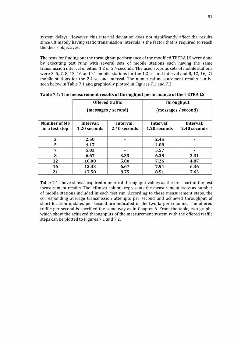
51
system delays. However, this interval deviation does not significantly affect the results since ultimately having static transmission intervals is the factor that is required to reach the thesis objectives. The tests for finding out the throughput performance of the modified TETRA LS were done by executing test runs with several sets of mobile stations each having the same transmission interval of either 1.2 or 2.4 seconds. The used steps as sets of mobile stations were 3, 5, 7, 8, 12, 16 and 21 mobile stations for the 1.2 second interval and 8, 12, 16, 21 mobile stations for the 2.4 second interval. The numerical measurement results can be seen below in Table 7.1 and graphically plotted in Figures 7.1 and 7.2. Table 7.1: The measurement results of throughput performance of the TETRA LS
Offered traffic
(messages / second)
Throughput
(messages / second)
Number of MS in a test step
Interval: 1.20 seconds
Interval: 2.40 seconds
Interval: 1.20 seconds
Interval: 2.40 seconds
3 2.50 2.45 5 4.17 4.08 7 5.83 5.57 8 6.67 3.33 6.38 3.31 12 10.00 5.00 7.26 4.87 16 13.33 6.67 7.94 6.36 21 17.50 8.75 8.51 7.63
Table 7.1 above shows acquired numerical throughput values as the first part of the test measurement results. The leftmost column represents the measurement steps as number of mobile stations included in each test run. According to these measurement steps, the corresponding average transmission attempts per second and achieved throughput of short location updates per second are indicated in the two larger columns. The offered traffic per second is specified the same way as in Chapter 6. From the table, two graphs which show the achieved throughputs of the measurement system with the offered traffic steps can be plotted to Figures 7.1 and 7.2.
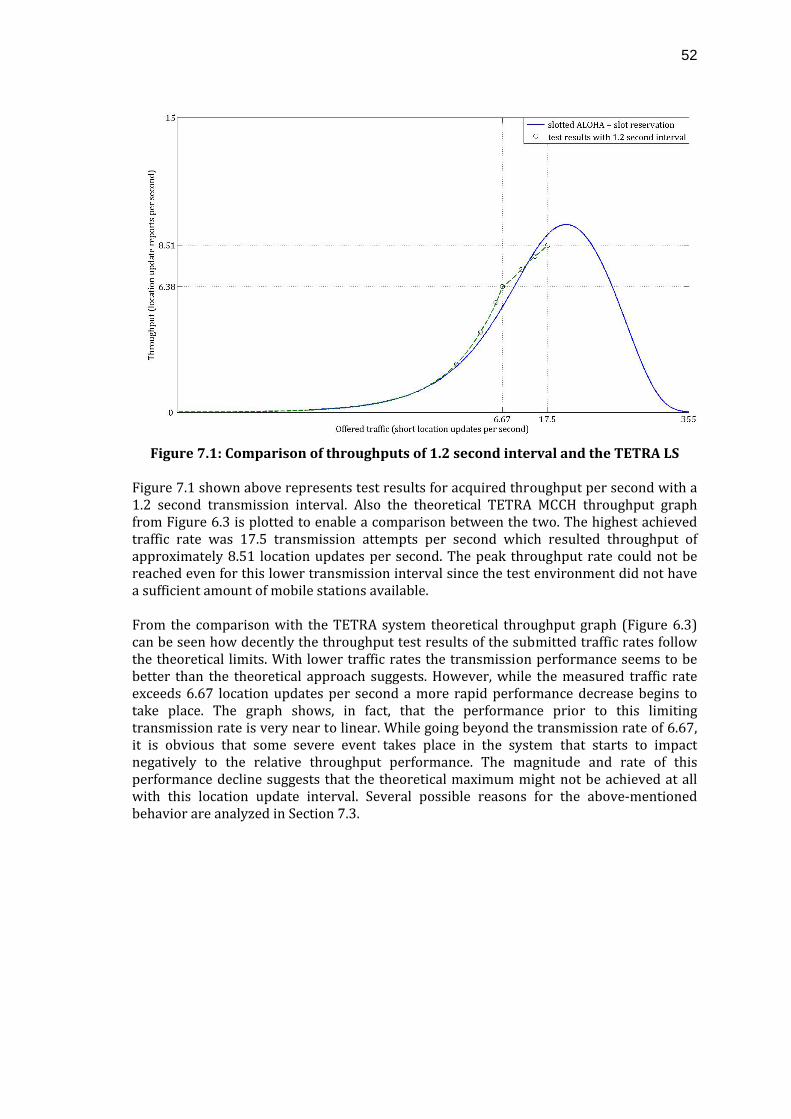
52
Figure 7.1: Comparison of throughputs of 1.2 second interval and the TETRA LS
Figure 7.1 shown above represents test results for acquired throughput per second with a 1.2 second transmission interval. Also the theoretical TETRA MCCH throughput graph from Figure 6.3 is plotted to enable a comparison between the two. The highest achieved traffic rate was 17.5 transmission attempts per second which resulted throughput of approximately 8.51 location updates per second. The peak throughput rate could not be reached even for this lower transmission interval since the test environment did not have a sufficient amount of mobile stations available. From the comparison with the TETRA system theoretical throughput graph (Figure 6.3) can be seen how decently the throughput test results of the submitted traffic rates follow the theoretical limits. With lower traffic rates the transmission performance seems to be better than the theoretical approach suggests. However, while the measured traffic rate exceeds 6.67 location updates per second a more rapid performance decrease begins to take place. The graph shows, in fact, that the performance prior to this limiting transmission rate is very near to linear. While going beyond the transmission rate of 6.67, it is obvious that some severe event takes place in the system that starts to impact negatively to the relative throughput performance. The magnitude and rate of this performance decline suggests that the theoretical maximum might not be achieved at all with this location update interval. Several possible reasons for the above‐mentioned behavior are analyzed in Section 7.3.
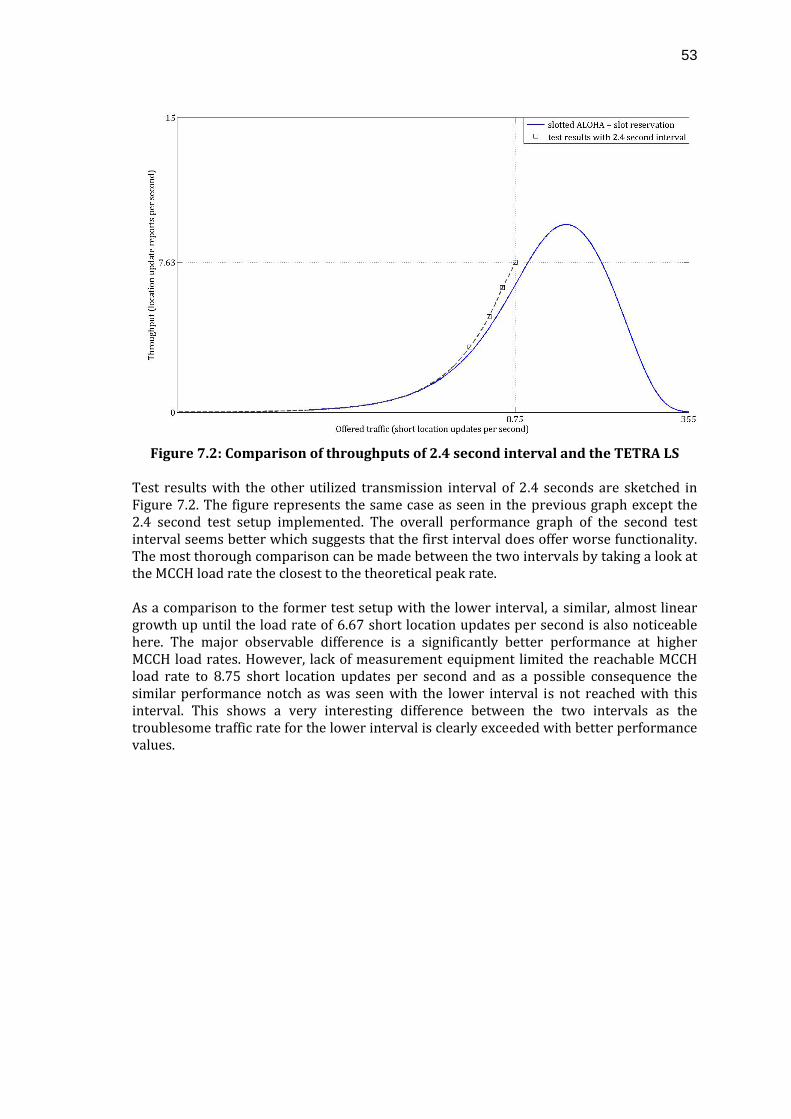
53
Figure 7.2: Comparison of throughputs of 2.4 second interval and the TETRA LS
Test results with the other utilized transmission interval of 2.4 seconds are sketched in Figure 7.2. The figure represents the same case as seen in the previous graph except the 2.4 second test setup implemented. The overall performance graph of the second test interval seems better which suggests that the first interval does offer worse functionality. The most thorough comparison can be made between the two intervals by taking a look at the MCCH load rate the closest to the theoretical peak rate. As a comparison to the former test setup with the lower interval, a similar, almost linear growth up until the load rate of 6.67 short location updates per second is also noticeable here. The major observable difference is a significantly better performance at higher MCCH load rates. However, lack of measurement equipment limited the reachable MCCH load rate to 8.75 short location updates per second and as a possible consequence the similar performance notch as was seen with the lower interval is not reached with this interval. This shows a very interesting difference between the two intervals as the troublesome traffic rate for the lower interval is clearly exceeded with better performance values.
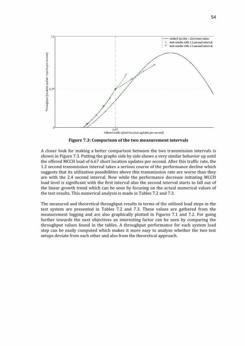
54
Figure 7.3: Comparison of the two measurement intervals
A closer look for making a better comparison between the two transmission intervals is shown in Figure 7.3. Putting the graphs side by side shows a very similar behavior up until the offered MCCH load of 6.67 short location updates per second. After this traffic rate, the 1.2 second transmission interval takes a serious course of the performance decline which suggests that its utilization possibilities above this transmission rate are worse than they are with the 2.4 second interval. Now while the performance decrease initiating MCCH load level is significant with the first interval also the second interval starts to fall out of the linear growth trend which can be seen by focusing on the actual numerical values of the test results. This numerical analysis is made in Tables 7.2 and 7.3. The measured and theoretical throughput results in terms of the utilized load steps in the test system are presented in Tables 7.2 and 7.3. These values are gathered from the measurement logging and are also graphically plotted in Figures 7.1 and 7.2. For going further towards the next objectives an interesting factor can be seen by comparing the throughput values found in the tables. A throughput performance for each system load step can be easily computed which makes it more easy to analyze whether the two test setups deviate from each other and also from the theoretical approach.
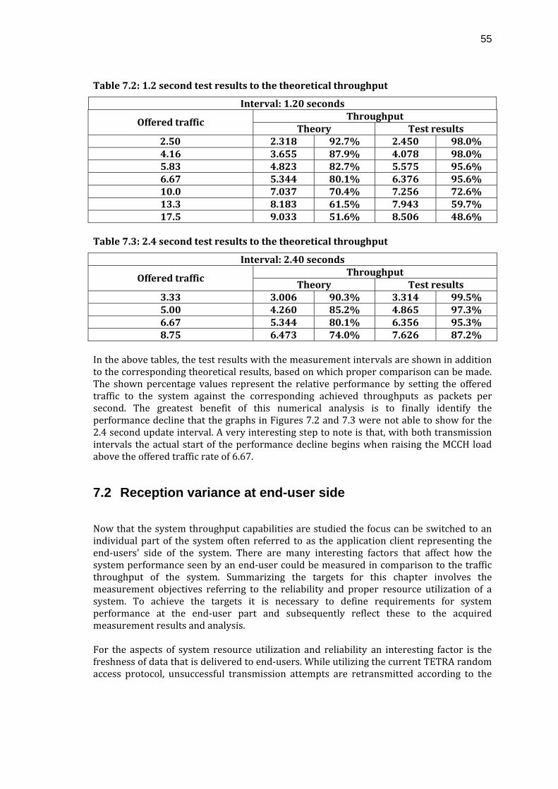
55
Table 7.2: 1.2 second test results to the theoretical throughput
Interval: 1.20 seconds Throughput
Offered traffic Theory Test results
2.50 2.318 92.7% 2.450 98.0% 4.16 3.655 87.9% 4.078 98.0% 5.83 4.823 82.7% 5.575 95.6% 6.67 5.344 80.1% 6.376 95.6% 10.0 7.037 70.4% 7.256 72.6% 13.3 8.183 61.5% 7.943 59.7% 17.5 9.033 51.6% 8.506 48.6%
Table 7.3: 2.4 second test results to the theoretical throughput
Interval: 2.40 seconds Throughput
Offered traffic Theory Test results
3.33 3.006 90.3% 3.314 99.5% 5.00 4.260 85.2% 4.865 97.3% 6.67 5.344 80.1% 6.356 95.3% 8.75 6.473 74.0% 7.626 87.2%
In the above tables, the test results with the measurement intervals are shown in addition to the corresponding theoretical results, based on which proper comparison can be made. The shown percentage values represent the relative performance by setting the offered traffic to the system against the corresponding achieved throughputs as packets per second. The greatest benefit of this numerical analysis is to finally identify the performance decline that the graphs in Figures 7.2 and 7.3 were not able to show for the 2.4 second update interval. A very interesting step to note is that, with both transmission intervals the actual start of the performance decline begins when raising the MCCH load above the offered traffic rate of 6.67.
7.2 Reception variance at end-user side
Now that the system throughput capabilities are studied the focus can be switched to an individual part of the system often referred to as the application client representing the end‐users' side of the system. There are many interesting factors that affect how the system performance seen by an end‐user could be measured in comparison to the traffic throughput of the system. Summarizing the targets for this chapter involves the measurement objectives referring to the reliability and proper resource utilization of a system. To achieve the targets it is necessary to define requirements for system performance at the end‐user part and subsequently reflect these to the acquired measurement results and analysis. For the aspects of system resource utilization and reliability an interesting factor is the freshness of data that is delivered to end‐users. While utilizing the current TETRA random access protocol, unsuccessful transmission attempts are retransmitted according to the
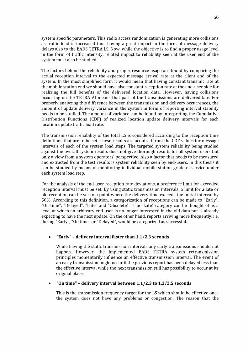
56
system specific parameters. This radio access randomization is generating more collisions as traffic load is increased thus having a great impact in the form of message delivery delays also to the EADS TETRA LS. Now, while the objective is to find a proper usage level in the form of traffic intensity, related impact to reliability seen at the user end of the system must also be studied. The factors behind the reliability and proper resource usage are found by comparing the actual reception interval to the expected message arrival rate at the client end of the system. In the most simplified form it would mean that having constant transmit rate at the mobile station end we should have also constant reception rate at the end‐user side for realizing the full benefits of the delivered location data. However, having collisions occurring on the TETRA AI means that part of the transmissions are delivered late. For properly analyzing this difference between the transmission and delivery occurrences, the amount of update delivery variance in the system in form of reporting interval stability needs to be studied. The amount of variance can be found by interpreting the Cumulative Distribution Functions (CDF) of realized location update delivery intervals for each location update traffic load rate. The transmission reliability of the total LS is considered according to the reception time definitions that are to be set. These results are acquired from the CDF values for message intervals of each of the system load steps. The targeted system reliability being studied against the overall system results does not give thorough results for all system users but only a view from a system operators' perspective. Also a factor that needs to be measured and extracted from the test results is system reliability seen by end‐users. In this thesis it can be studied by means of monitoring individual mobile station grade of service under each system load step. For the analysis of the end‐user reception rate deviations, a preference limit for exceeded reception interval must be set. By using static transmission intervals, a limit for a late or old reception can be set to a point where the delivery time exceeds the initial interval by 50%. According to this definition, a categorization of receptions can be made to "Early", "On time", "Delayed", "Late" and "Obsolete". The "Late" category can be thought of as a level at which an arbitrary end‐user is no longer interested in the old data but is already expecting to have the next update. On the other hand, reports arriving more frequently, i.e. during "Early", "On time" or "Delayed", would be categorized as successful.
• "Early" – delivery interval faster than 1.1/2.3 seconds
While having the static transmission intervals any early transmissions should not happen. However, the implemented EADS TETRA system retransmission principles momentarily influence an effective transmission interval. The event of an early transmission might occur if the previous report has been delayed less than the effective interval while the next transmission still has possibility to occur at its original place.
• "On time" – delivery interval between 1.1/2.3 to 1.3/2.5 seconds
This is the transmission frequency target for the LS which should be effective once the system does not have any problems or congestion. The reason that the
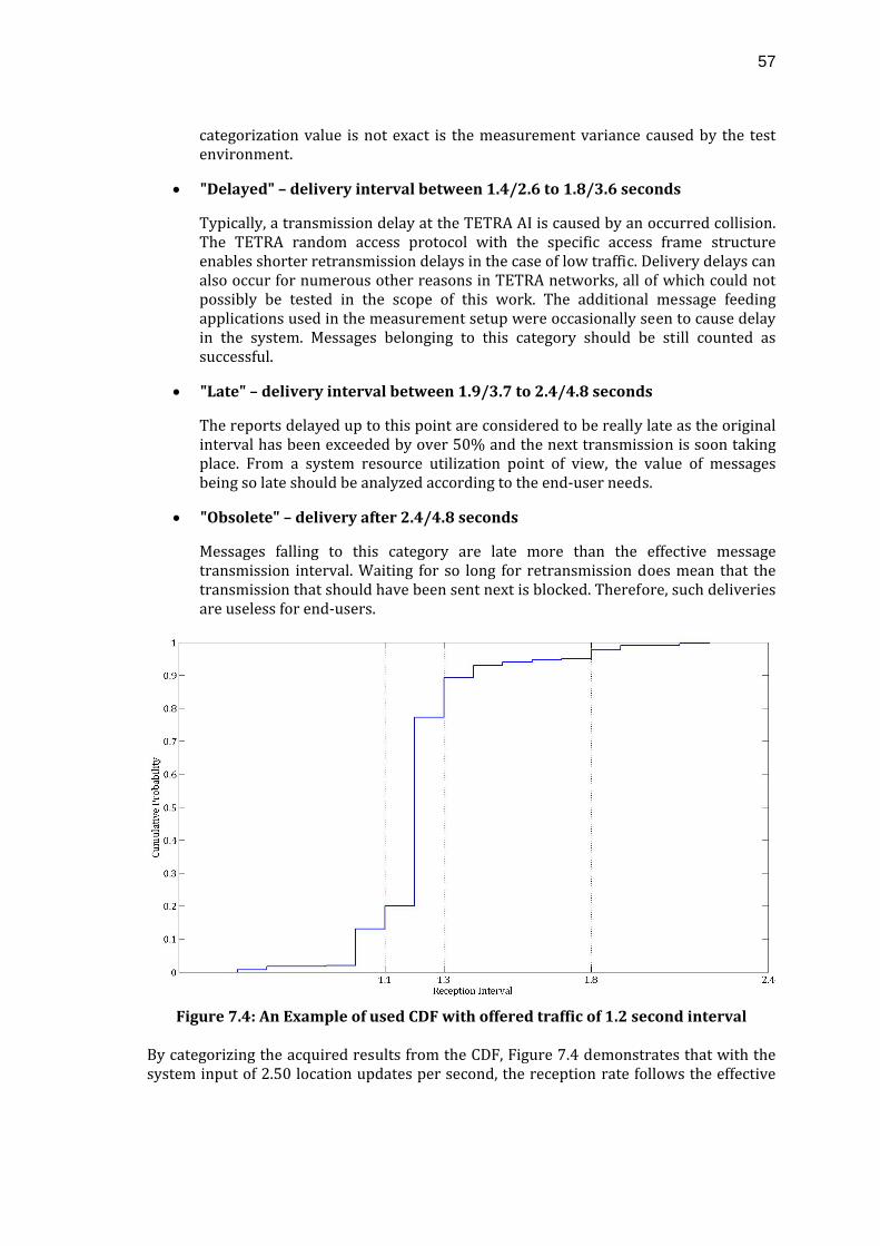
57
categorization value is not exact is the measurement variance caused by the test environment.
• "Delayed" – delivery interval between 1.4/2.6 to 1.8/3.6 seconds
Typically, a transmission delay at the TETRA AI is caused by an occurred collision. The TETRA random access protocol with the specific access frame structure enables shorter retransmission delays in the case of low traffic. Delivery delays can also occur for numerous other reasons in TETRA networks, all of which could not possibly be tested in the scope of this work. The additional message feeding applications used in the measurement setup were occasionally seen to cause delay in the system. Messages belonging to this category should be still counted as successful.
• "Late" – delivery interval between 1.9/3.7 to 2.4/4.8 seconds
The reports delayed up to this point are considered to be really late as the original interval has been exceeded by over 50% and the next transmission is soon taking place. From a system resource utilization point of view, the value of messages being so late should be analyzed according to the end‐user needs.
• "Obsolete" – delivery after 2.4/4.8 seconds
Messages falling to this category are late more than the effective message transmission interval. Waiting for so long for retransmission does mean that the transmission that should have been sent next is blocked. Therefore, such deliveries are useless for end‐users.
Figure 7.4: An Example of used CDF with offered traffic of 1.2 second interval
By categorizing the acquired results from the CDF, Figure 7.4 demonstrates that with the system input of 2.50 location updates per second, the reception rate follows the effective
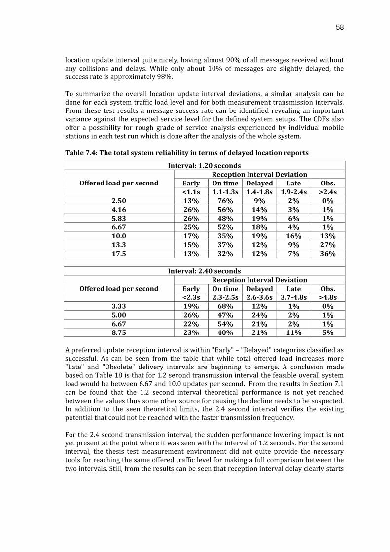
58
location update interval quite nicely, having almost 90% of all messages received without any collisions and delays. While only about 10% of messages are slightly delayed, the success rate is approximately 98%. To summarize the overall location update interval deviations, a similar analysis can be done for each system traffic load level and for both measurement transmission intervals. From these test results a message success rate can be identified revealing an important variance against the expected service level for the defined system setups. The CDFs also offer a possibility for rough grade of service analysis experienced by individual mobile stations in each test run which is done after the analysis of the whole system. Table 7.4: The total system reliability in terms of delayed location reports
Interval: 1.20 seconds Reception Interval Deviation
Early On time Delayed Late Obs. Offered load per second <1.1s 1.11.3s 1.41.8s 1.92.4s >2.4s
2.50 13% 76% 9% 2% 0% 4.16 26% 56% 14% 3% 1% 5.83 26% 48% 19% 6% 1% 6.67 25% 52% 18% 4% 1% 10.0 17% 35% 19% 16% 13% 13.3 15% 37% 12% 9% 27% 17.5 13% 32% 12% 7% 36%
Interval: 2.40 seconds
Reception Interval Deviation Early On time Delayed Late Obs. Offered load per second <2.3s 2.32.5s 2.63.6s 3.74.8s >4.8s
3.33 19% 68% 12% 1% 0% 5.00 26% 47% 24% 2% 1% 6.67 22% 54% 21% 2% 1% 8.75 23% 40% 21% 11% 5%
A preferred update reception interval is within "Early" – "Delayed" categories classified as successful. As can be seen from the table that while total offered load increases more "Late" and "Obsolete" delivery intervals are beginning to emerge. A conclusion made based on Table 18 is that for 1.2 second transmission interval the feasible overall system load would be between 6.67 and 10.0 updates per second. From the results in Section 7.1 can be found that the 1.2 second interval theoretical performance is not yet reached between the values thus some other source for causing the decline needs to be suspected. In addition to the seen theoretical limits, the 2.4 second interval verifies the existing potential that could not be reached with the faster transmission frequency. For the 2.4 second transmission interval, the sudden performance lowering impact is not yet present at the point where it was seen with the interval of 1.2 seconds. For the second interval, the thesis test measurement environment did not quite provide the necessary tools for reaching the same offered traffic level for making a full comparison between the two intervals. Still, from the results can be seen that reception interval delay clearly starts
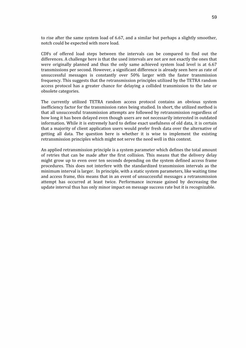
59
to rise after the same system load of 6.67, and a similar but perhaps a slightly smoother, notch could be expected with more load. CDFs of offered load steps between the intervals can be compared to find out the differences. A challenge here is that the used intervals are not are not exactly the ones that were originally planned and thus the only same achieved system load level is at 6.67 transmissions per second. However, a significant difference is already seen here as rate of unsuccessful messages is constantly over 50% larger with the faster transmission frequency. This suggests that the retransmission principles utilized by the TETRA random access protocol has a greater chance for delaying a collided transmission to the late or obsolete categories. The currently utilized TETRA random access protocol contains an obvious system inefficiency factor for the transmission rates being studied. In short, the utilized method is that all unsuccessful transmission attempts are followed by retransmission regardless of how long it has been delayed even though users are not necessarily interested in outdated information. While it is extremely hard to define exact usefulness of old data, it is certain that a majority of client application users would prefer fresh data over the alternative of getting all data. The question here is whether it is wise to implement the existing retransmission principles which might not serve the need well in this context. An applied retransmission principle is a system parameter which defines the total amount of retries that can be made after the first collision. This means that the delivery delay might grow up to even over ten seconds depending on the system defined access frame procedures. This does not interfere with the standardized transmission intervals as the minimum interval is larger. In principle, with a static system parameters, like waiting time and access frame, this means that in an event of unsuccessful messages a retransmission attempt has occurred at least twice. Performance increase gained by decreasing the update interval thus has only minor impact on message success rate but it is recognizable.
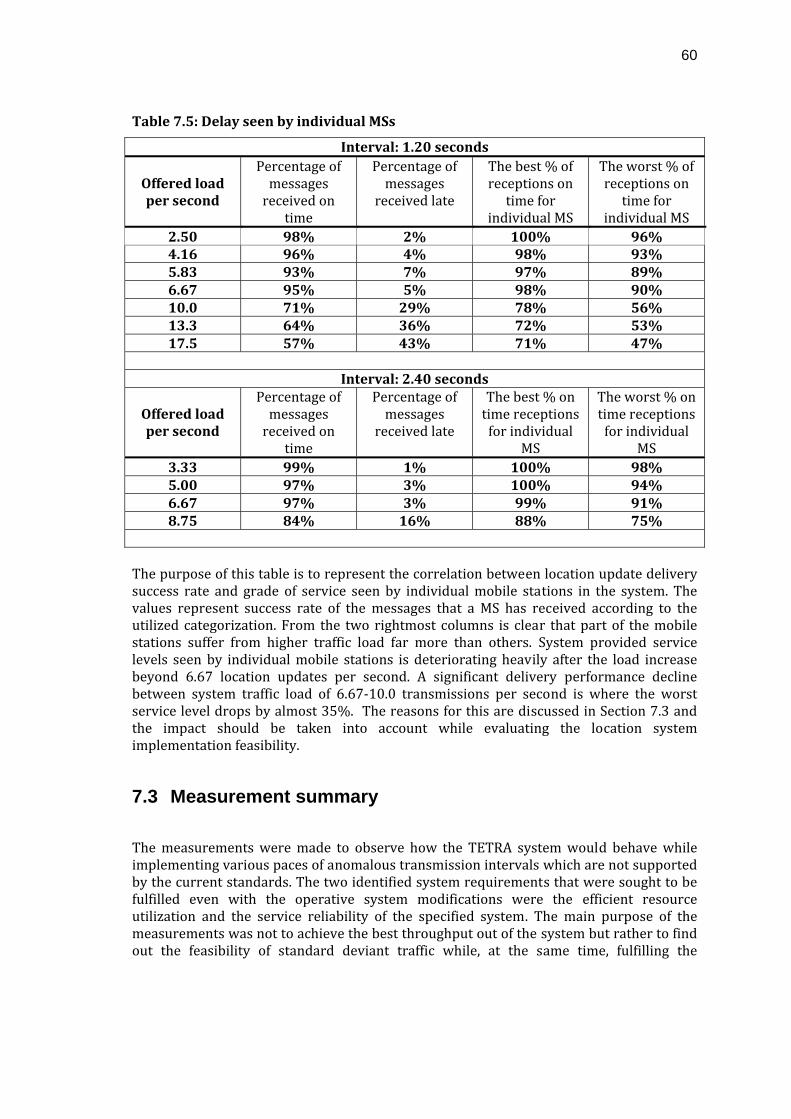
60
Table 7.5: Delay seen by individual MSs
Interval: 1.20 seconds
Offered load per second
Percentage of messages received on
time
Percentage of messages
received late
The best % of receptions on time for
individual MS
The worst % of receptions on time for
individual MS 2.50 98% 2% 100% 96% 4.16 96% 4% 98% 93% 5.83 93% 7% 97% 89% 6.67 95% 5% 98% 90% 10.0 71% 29% 78% 56% 13.3 64% 36% 72% 53% 17.5 57% 43% 71% 47%
Interval: 2.40 seconds
Offered load per second
Percentage of messages received on
time
Percentage of messages
received late
The best % on time receptions for individual
MS
The worst % on time receptions for individual
MS 3.33 99% 1% 100% 98% 5.00 97% 3% 100% 94% 6.67 97% 3% 99% 91% 8.75 84% 16% 88% 75%
The purpose of this table is to represent the correlation between location update delivery success rate and grade of service seen by individual mobile stations in the system. The values represent success rate of the messages that a MS has received according to the utilized categorization. From the two rightmost columns is clear that part of the mobile stations suffer from higher traffic load far more than others. System provided service levels seen by individual mobile stations is deteriorating heavily after the load increase beyond 6.67 location updates per second. A significant delivery performance decline between system traffic load of 6.67‐10.0 transmissions per second is where the worst service level drops by almost 35%. The reasons for this are discussed in Section 7.3 and the impact should be taken into account while evaluating the location system implementation feasibility.
7.3 Measurement summary
The measurements were made to observe how the TETRA system would behave while implementing various paces of anomalous transmission intervals which are not supported by the current standards. The two identified system requirements that were sought to be fulfilled even with the operative system modifications were the efficient resource utilization and the service reliability of the specified system. The main purpose of the measurements was not to achieve the best throughput out of the system but rather to find out the feasibility of standard deviant traffic while, at the same time, fulfilling the
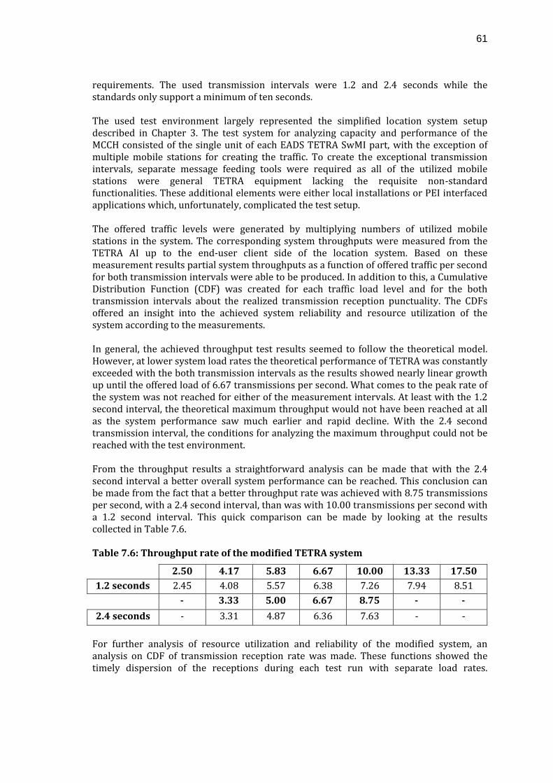
61
requirements. The used transmission intervals were 1.2 and 2.4 seconds while the standards only support a minimum of ten seconds. The used test environment largely represented the simplified location system setup described in Chapter 3. The test system for analyzing capacity and performance of the MCCH consisted of the single unit of each EADS TETRA SwMI part, with the exception of multiple mobile stations for creating the traffic. To create the exceptional transmission intervals, separate message feeding tools were required as all of the utilized mobile stations were general TETRA equipment lacking the requisite non‐standard functionalities. These additional elements were either local installations or PEI interfaced applications which, unfortunately, complicated the test setup. The offered traffic levels were generated by multiplying numbers of utilized mobile stations in the system. The corresponding system throughputs were measured from the TETRA AI up to the end‐user client side of the location system. Based on these measurement results partial system throughputs as a function of offered traffic per second for both transmission intervals were able to be produced. In addition to this, a Cumulative Distribution Function (CDF) was created for each traffic load level and for the both transmission intervals about the realized transmission reception punctuality. The CDFs offered an insight into the achieved system reliability and resource utilization of the system according to the measurements. In general, the achieved throughput test results seemed to follow the theoretical model. However, at lower system load rates the theoretical performance of TETRA was constantly exceeded with the both transmission intervals as the results showed nearly linear growth up until the offered load of 6.67 transmissions per second. What comes to the peak rate of the system was not reached for either of the measurement intervals. At least with the 1.2 second interval, the theoretical maximum throughput would not have been reached at all as the system performance saw much earlier and rapid decline. With the 2.4 second transmission interval, the conditions for analyzing the maximum throughput could not be reached with the test environment. From the throughput results a straightforward analysis can be made that with the 2.4 second interval a better overall system performance can be reached. This conclusion can be made from the fact that a better throughput rate was achieved with 8.75 transmissions per second, with a 2.4 second interval, than was with 10.00 transmissions per second with a 1.2 second interval. This quick comparison can be made by looking at the results collected in Table 7.6. Table 7.6: Throughput rate of the modified TETRA system
2.50 4.17 5.83 6.67 10.00 13.33 17.50 1.2 seconds 2.45 4.08 5.57 6.38 7.26 7.94 8.51
3.33 5.00 6.67 8.75
2.4 seconds ‐ 3.31 4.87 6.36 7.63 ‐ ‐ For further analysis of resource utilization and reliability of the modified system, an analysis on CDF of transmission reception rate was made. These functions showed the timely dispersion of the receptions during each test run with separate load rates.
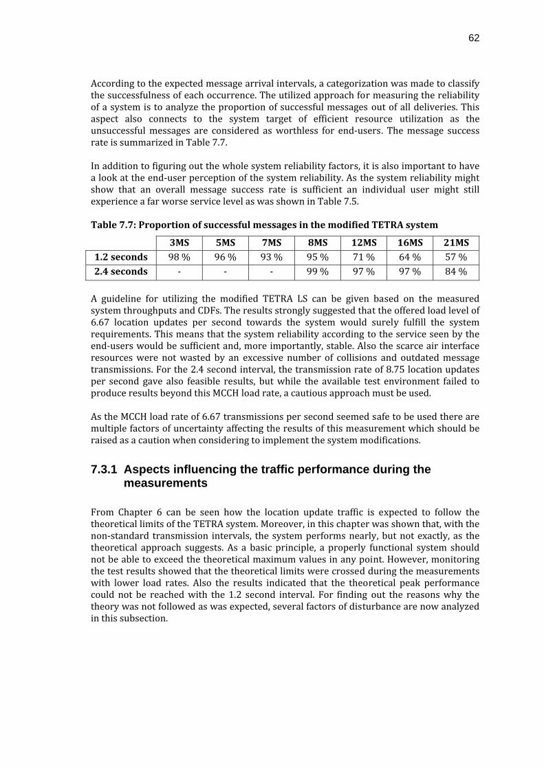
62
According to the expected message arrival intervals, a categorization was made to classify the successfulness of each occurrence. The utilized approach for measuring the reliability of a system is to analyze the proportion of successful messages out of all deliveries. This aspect also connects to the system target of efficient resource utilization as the unsuccessful messages are considered as worthless for end‐users. The message success rate is summarized in Table 7.7. In addition to figuring out the whole system reliability factors, it is also important to have a look at the end‐user perception of the system reliability. As the system reliability might show that an overall message success rate is sufficient an individual user might still experience a far worse service level as was shown in Table 7.5. Table 7.7: Proportion of successful messages in the modified TETRA system
3MS 5MS 7MS 8MS 12MS 16MS 21MS 1.2 seconds 98 % 96 % 93 % 95 % 71 % 64 % 57 % 2.4 seconds ‐ ‐ ‐ 99 % 97 % 97 % 84 % A guideline for utilizing the modified TETRA LS can be given based on the measured system throughputs and CDFs. The results strongly suggested that the offered load level of 6.67 location updates per second towards the system would surely fulfill the system requirements. This means that the system reliability according to the service seen by the end‐users would be sufficient and, more importantly, stable. Also the scarce air interface resources were not wasted by an excessive number of collisions and outdated message transmissions. For the 2.4 second interval, the transmission rate of 8.75 location updates per second gave also feasible results, but while the available test environment failed to produce results beyond this MCCH load rate, a cautious approach must be used. As the MCCH load rate of 6.67 transmissions per second seemed safe to be used there are multiple factors of uncertainty affecting the results of this measurement which should be raised as a caution when considering to implement the system modifications.
7.3.1 Aspects influencing the traffic performance during the measurements
From Chapter 6 can be seen how the location update traffic is expected to follow the theoretical limits of the TETRA system. Moreover, in this chapter was shown that, with the non‐standard transmission intervals, the system performs nearly, but not exactly, as the theoretical approach suggests. As a basic principle, a properly functional system should not be able to exceed the theoretical maximum values in any point. However, monitoring the test results showed that the theoretical limits were crossed during the measurements with lower load rates. Also the results indicated that the theoretical peak performance could not be reached with the 1.2 second interval. For finding out the reasons why the theory was not followed as was expected, several factors of disturbance are now analyzed in this subsection.
63
Applications controlling the Mobile Stations
The standard location system described in Chapter 3 could not be used as such for the measurements. A significant variable in the test environment was the additional message feeding applications which had to be used to control the mobile stations. These elements were introduced because the available MSs were general products thus compliant to the current standards meaning that the non‐standard transmission intervals could not be implemented. The instability and immatureness of these applications caused some message transmission errors during the measurements. Even though the measurements were able to be quite successfully done, these applications are a source of uncertainty and errors in the results. The major effect was that the transmission intervals were not as static as they could have been since the applications did not tolerate failures within the communication between a MS. An occurred failure usually caused a break in the service. The failures were seen to be proportional to the system traffic rate and congestion in the AI. These failures might have been a reason for the shorter interval not reaching even close to the theoretical peak performance as part of the transmitters were not constantly operational. Any major impacts with the lower system load levels could not be seen.
Mobile Station behavior
Probably one of the most significant factors influencing the traffic is how mobile stations behave in the TETRA system. The basis for this uncertainty is that the TETRA standard does not specify exact functionalities for mobile station equipment. Needless to say that the mobile stations follow the standardized interface and provides other system specific features but the ultimate implementation is up to the equipment manufacturer. This relates mainly to the open TETRA PMR market of which mobile station business plays a major part. Mobile stations’ influence on the location update traffic seen in the location system can be narrowed down to several identifiable operational algorithms which can be outlined. In addition to those there are multiple other schemes of operation which can only be mentioned in this context since the specific influence is not known. The greatest influence on the traffic under study might be caused by retransmission algorithms implemented on mobile stations. Basically, this means the decision of what will be done when a collision is observed by not receiving any downlink acknowledgement from a control channel on time. The basic principle is like ALOHA specifies that the collided message is randomly retransmitted, but in the TETRA, random access protocol retransmission attempts do not happen according to the Poisson process. The retransmission algorithm follows a given scheme that it randomizes over the next access frame and only after waiting for a certain time for the acknowledgement. The above process is influencing transmissions by controlling the retransmission access possibilities, thus helping to keep the slotted ALOHA based TETRA system more stable. One other aspect is the task prioritization inside a mobile station between different operations. As a valid example closely related to the measurements is the message feeding applications that are interfacing the MSs through the TETRA PEI by utilizing an AT command interface. This interface has a lower priority over many other MS operations
64
and thus the majority of the failures occurred with the applications might have resulted also from these factors. These mobile station originated factors have influence on the message transmission interval stability, and thus the overall system reliability during the measurements. Together with the TETRA random access protocol implemented access frame structure, mobile stations control the stability of the solution.
Access frame structure
As a mobile station retransmission procedure was dependent on a prevailing frame size it surely has an impact on traffic. The TETRA standard defines two types of models for frame size allocation which use continuous and discontinuous frame markers called rolling access frames and discrete access frames respectively (ETSI 2008b). In the measurements done in this thesis, the discrete access scheme was used and it is explained a little in this chapter. So when a random access attempt collides in the AI a mobile station enters the retransmission state. The initial process is to wait for expiry of a certain waiting timer before acting any further. The waiting timer procedure is included in the TETRA system for the MAC layer to indicate when an access request has failed. This means that each mobile station being in a retransmission state and having passed the waiting period will randomize over the next occurring access frame. (ETSI 2008b.) An exact number of mobile stations simultaneously in the retransmission state cannot be specified as it is ultimately dependent on random probabilities. Nevertheless, one could expect for it to correlate with the instantaneous random access load seen in a control channel. Now, if a system would have a constant frame size, it could mean that there are fewer slots than there are random accesses or that the utilized access frame length is too large and resource usage is inefficient and access delays are excessive. Therefore, the discrete access scheme is used to control the access frame length according to the effective MCCH load. In the case of consecutive collision occurrences, the transmission is retried multiple times. The standard defines the maximum access frame to 32 subslots which means the maximum delay of about two seconds for a single retransmission. (ETSI 2008b.) This means that in the worst case of multiple retransmissions a message can be delayed by even more than ten seconds. The discrete access scheme was applied to the executed measurements with the non‐standard traffic types in a TETRA system. The crucial delay caused by this scheme is seen in effect when a location update is delayed beyond “the next” update trigger. This scenario is possible with the 1.2 and 2.4 second update intervals since retransmission delay might take longer than the initially set transmission interval. As was expected, the test results show that frame size grows with an increased traffic load on the MCCH. In the measurement results this frame length growth was seen extremely harmful for the 1.2 second interval since “Late” and “Obsolete” deliveries started to significantly rise. With the 2.4 second interval, effects of the same magnitude did not yet occur but testing with a higher a load this could be expected to happen.
65
The access frame structure significantly affects the delay which collided transmissions experience. On the other hand, however, it increases the retransmission frequency with smaller system loads, but with more load, it delays the retransmissions to keep the system more stable.
Nonrandom transmission process
The standard model by using the LIP control messaging for requesting location updates from mobile stations could not be utilized during the measurements. The reason for this was that there is no support for altering the mobile stations’ update interval below the standard limitations directly by sending an appropriate LIP trigger command. Since this opportunity was not present, the additional message feeding tools were used for getting the desired location update intervals. Nevertheless, while using the required tools for creating the traffic the measurement’s operational procedures were not as efficient as would have been hoped for. In TETRA operational use the initial random accesses are randomized according to the Poisson process. Because the message feeding tools had to be used manually, this could not be produced in the test environment, and thus the initial randomization was not realized according to the typical TETRA traffic profile. However, the LS might operate this way in cases where a service request is made for multiple field units simultaneously. The utilized constant transmission interval is not also as random as it should be for considering the ALOHA to be fully effective. Transmissions happening with static intervals do not have the same collision probabilities as those might be grouped or dispersed depending on at what time instance the initializations take place. This can add variation reliability seen by individual mobile stations as some might have higher collision probabilities. The initialization procedure is seen to have the most impact on the system performance seen with the lower transmission intervals. The theoretical performance is exceeded as the static transmissions are not randomized according to the Poisson process.
The capture effect
The capture effect brought up in Chapter 6 was neglected during this thesis as the net impacts affecting the system performance are largely uncertain. However, the influence of such phenomenon is recognizable in common wireless networks.
66
8 Conclusions
In this thesis location update traffic generated by the Location System in the ETSI specified TETRA systems has been under study. The TETRA was developed to fulfill special end‐user requirements for a type of wireless radio communication systems categorized as the Professional Mobile Radio. The thesis objective was to find out whether the location update minimum interval defined in the TETRA standard could be neglected at times to enable faster field unit position updates. Measurements were done in a real TETRA environment to support this objective and to see how the TETRA system would actually behave while implementing various paces of anomalous transmission intervals. Efficient resource utilization and system reliability were identified as two functional system requirements which are fulfilled by both, the standard TETRA and LS solutions. Furthermore, these system characteristics were recognized as being subject to degradation by the proposed system modification and therefore, maintainability of these high‐level system requirements were set as the primary objective. The task was to find out system performance limits so that it benefits the end‐users the most while still avoiding any violation of these targets, thus evading any event which could severely degrade the overall system performance and usability. This means that the main purpose was not to achieve the best throughput out of the system, but to proportion the pursued LS service possibilities with the measured impacts according to the resulting end‐user gain. In the measurements the maximum MCCH load levels were sought for each transmission interval while keeping up the satisfactory system performance and requirements. From the test results it was found that the MCCH load level of 6.67 location updates per second seemed to maintain the system requirements for both 1.2 and 2.4 second transmission intervals with approximately 3 – 5 % message loss. In addition to this, the load level of 8.75 location updates per second, with the 2.4 second update interval, gave also feasible results with roughly 16 % of messages per second categorized as unsuccessful. Ultimately, the acceptability of such error ratios is up to service requirements client application users and service providers are setting for the LS. The main reasons for the growing message loss rates while increasing the MCCH load rate were found by studying the distribution functions of transmission attempts. The CDFs are included in Appendices 1 – 20. An observation was made that an increase in channel load rate causes eventually more and more collisions thus resulting into a larger probability of retransmissions. Consecutive retransmissions for a single message transmission cause cumulative increase in experienced delay and when such delay exceeds the utilized trigger update interval message loss occurs. In addition to this a system implementations of various access frame structures may affect significant delays to retransmission attempts. Furthermore, the messages which are lost are newer than the one being delayed which leads to an inevitable misuse of resources as the outdated message is eventually successfully transmitted instead of the discarded updates. Significant thing to notice is that the test environment used for running the measurements could not reach any higher load rates for the latter interval and thus a more thorough test setup should be used to verify the feasibility of the higher load level. With the acquired measurement results one could say that the thesis objectives were met only partially while higher load rates could not be tested thoroughly. While the safe usage limit was achieved
67
with a MCCH load rate of 6.67 location updates per second, the result suggests that the current system implementation could support up to eight objects to be tracked once in a 1.2 seconds or alternatively, 16 with 2.4 second interval with the resources of one control channel. Especially for the interval of 1.2 seconds, the results showed that usability stays quite low with the current system implementation. While utilizing the higher MCCH load rates the message failure rate grew rapidly to nearly 45 % of all attempted location update transmissions. For the 2.4 second interval, there seemed to be more potential as clearly higher MCCH load rates could be utilized while still fulfilling the system requirements. The seen performance improvement while increasing the transmission interval also suggests that the standardized minimum update limits are there to ensure stabile operation in everyday use. A much larger and comprehensive test setup could be arranged for having more precise and thorough studies about further possibilities of altering the TETRA LS parameters and the TETRA standard. An overall assessment about the measurements done for this thesis would be that the available test environment did not provide as versatile testing possibilities as one could have hoped for resulting into just partial performance analysis. A more desirable, but unreachable, approach would have been to run tests with various location update transmission intervals all the way up to the standard specification of ten seconds. This way the results would have shown more detailed information about possibilities for the TETRA system usage. The shortage of mobile station equipment was not fully anticipated while content for the thesis topic was being assembled. Ultimately, the only interval which was sufficiently tested with the given number of mobile stations was the 1.2 seconds. Even for the 1.2 second interval a typical measurement point of the system load giving the theoretical maximum could not be reached. A significant possibility for reaching higher system performance with lower transmission intervals could actually be found by altering the current system specification. As mentioned the increased probability of collisions in the TETRA Air Interface is the reason why transmission throughput starts to significantly decline after reaching a certain point in MCCH load. The major aspect influencing the system performance was the utilized retransmission principle which seemed to block the system from reaching the full theoretical performance since retransmission waiting periods were exceeding the shorter transmission intervals. A possibility for resolving this issue could be to implement an option to enable a categorization of location update traffic so that it would not be subject to the typically utilized retransmission principles. This could mean a solution where the maximum acceptable retransmission delay would equal some portion of the effective location update interval and if it is exceeded any further retransmissions would be discarded. The solution implementation could be evaluated based on the actual client application data usage thus it should be determined whether a retransmission sequence should only last until the data becomes obsolete or any other delay timer after which it would be useless to the end‐users. The simplest solution would be to disable retransmission for all message types categorized as location updates as outdated data is not often valued by the end‐users.
68
References
Arnbak, J.C. & van Blitterswijk W., 1987. Capacity of Slotted ALOHA in Rayleigh‐FadingChannels. IEEE journal on selected areas in communications, 5 (2), pp. 261‐269.
DE (Daniels Electronics Ltd.), 2004. P25 Training Guide. Victoria BC, Canada: Daniels
Electronics Ltd. 69 p. Desourdis, R.I.Jr. et al., 2002. Emerging Public Safety Wireless Communication Systems.
Norwood (MA): Artech House. ISBN 0‐89006‐575‐6. DHS (Department of Homeland Security), 2006. Statement of Requirements for Public
Safety Wireless Communications & Interoperability. [Online] Available at: http://www.npstc.org/documents/SRSoR_V11_030606.pdf [Accessed 14 January 2010].
Dunlop, J. Girma, D. & Irvine, J., 1999. Digital Mobile Communications and the TETRA
System. Chichester: John Wiley & Sons. ISBN 0‐471‐98792‐1. Dunlop, J. Irvine, J. Robertson, D & Cosimini, P., 1995. Performance of a Statistically
Multiplexed Access Mechanism for a TDMA Radio Interface, IEEE Personal Communications. Vol 2 No 3 June 1995 pp 56‐61.
EADS (European Aeronautic Defence and Space Company), 2006. EADS TETRA Primer.
[Online] Available at: http://www.eads.com/xml/content/ OF00000000400004/1/87/40869871.pdf [Accessed 14 January 2010].
EADS (European Aeronautic Defence and Space Company), 2009a. Professional Mobile
Radio. [Online] Available at: www.eads.com/pmr [Accessed 14 January 2010]. EADS (European Aeronautic Defence and Space Company), 2009b. Product
Documentation. ETSI (The European Telecommunications Standards Institute), 2008a. ETSI TS 100 392‐
18‐1 Terrestrial Trunked Radio (TETRA); Voice plus Data (V+D) and Direct Mode Operation (DMO); Part 18: Air interface optimized applications; Sub‐part 1: Location Information Protocol (LIP), Sophia Antipolis (France): ETSI.
ETSI (The European Telecommunications Standards Institute), 2008b. ETSI TS 100 392‐2
Terrestrial Trunked Radio (TETRA); Voice plus Data (V+D) and Direct Mode Operation (DMO); Part 2: Air Interface (AI), Sophia Antipolis (France): ETSI.
Gray, D., 2003. TETRA: The Advocate's Handbook. Cornwall: TETRA Advocate. ISBN 0‐
9544651‐0‐5. Intven, H. Oliver, J. Sepúlveda, E. & McCarthy, T (ed.)., 2000. Telecommunications
Regulation Handbook. Washington, USA: The World Bank. 378 p. ISBN 0‐9697178‐7‐3.
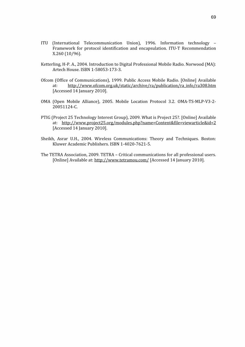
69
ITU (International Telecommunication Union), 1996. Information technology –
Framework for protocol identification and encapsulation. ITU‐T Recommendation X.260 (10/96).
Ketterling, H‐P. A., 2004. Introduction to Digital Professional Mobile Radio. Norwood (MA):
Artech House. ISBN 1‐58053‐173‐3. Ofcom (Office of Communications), 1999. Public Access Mobile Radio. [Online] Available
at: http://www.ofcom.org.uk/static/archive/ra/publication/ra_info/ra308.htm [Accessed 14 January 2010].
OMA (Open Mobile Alliance), 2005. Mobile Location Protocol 3.2. OMA‐TS‐MLP‐V3‐2‐
20051124‐C. PTIG (Project 25 Technology Interest Group), 2009. What is Project 25?. [Online] Available
at: http://www.project25.org/modules.php?name=Content&file=viewarticle&id=2 [Accessed 14 January 2010].
Sheikh, Asrar U.H., 2004. Wireless Communications: Theory and Techniques. Boston:
Kluwer Academic Publishers. ISBN 1‐4020‐7621‐5. The TETRA Association, 2009. TETRA – Critical communications for all professional users.
[Online] Available at: http://www.tetramou.com/ [Accessed 14 January 2010].
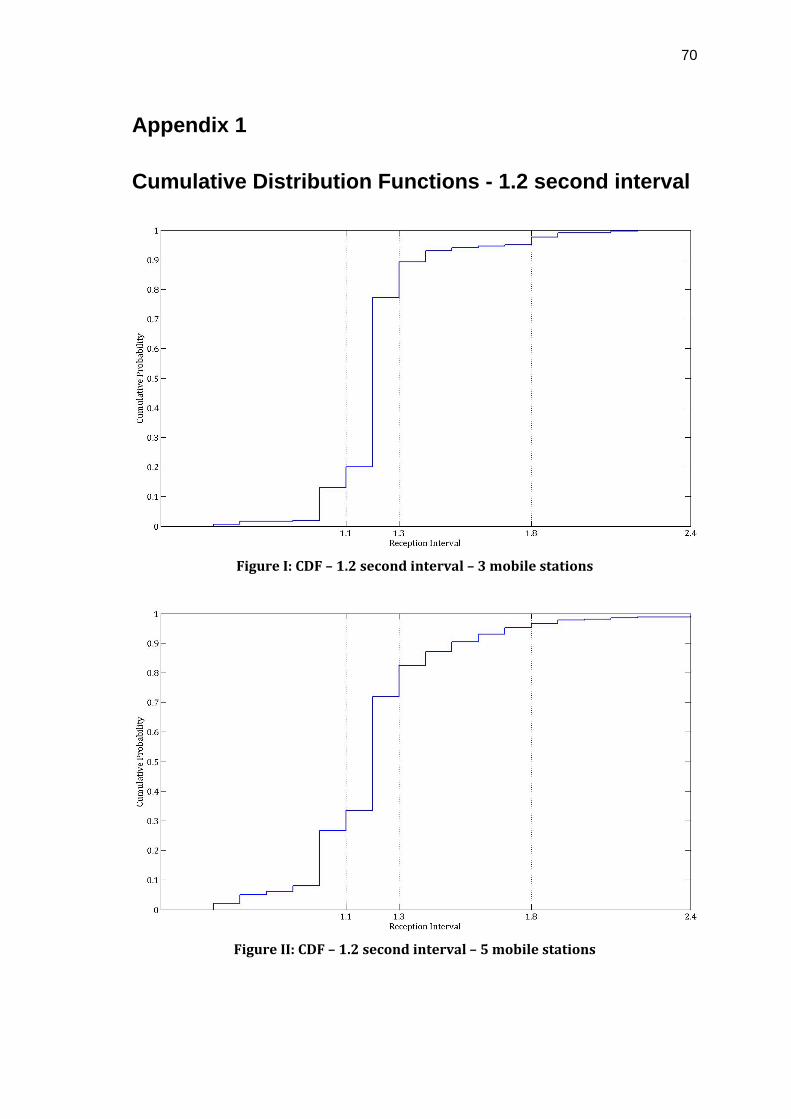
70
Appendix 1
Cumulative Distribution Functions - 1.2 second interval
Figure I: CDF – 1.2 second interval – 3 mobile stations
Figure II: CDF – 1.2 second interval – 5 mobile stations
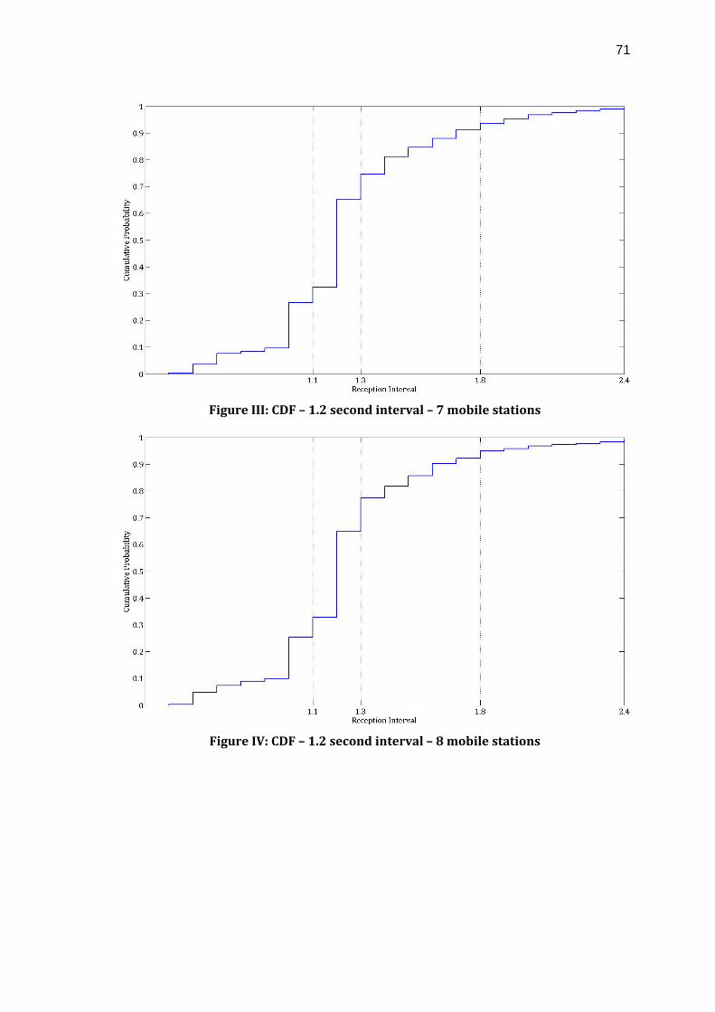
71
Figure III: CDF – 1.2 second interval – 7 mobile stations
Figure IV: CDF – 1.2 second interval – 8 mobile stations
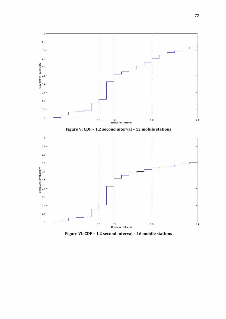
72
Figure V: CDF – 1.2 second interval – 12 mobile stations
Figure VI: CDF – 1.2 second interval – 16 mobile stations
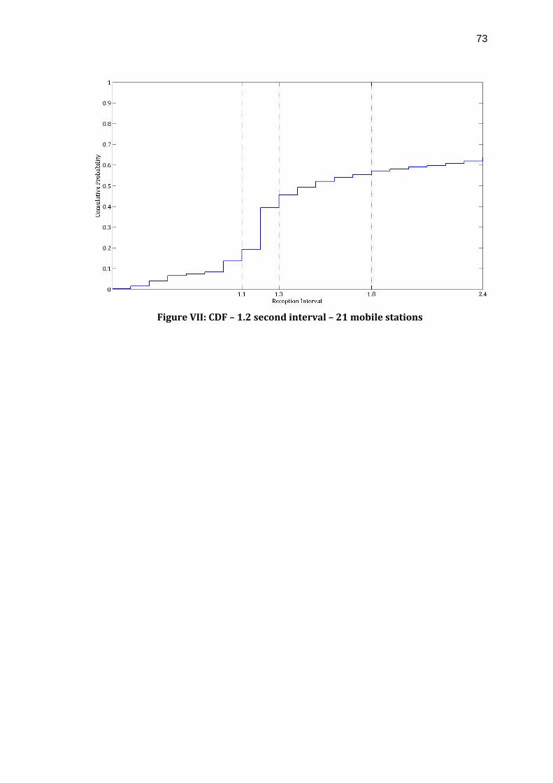
73
Figure VII: CDF – 1.2 second interval – 21 mobile stations
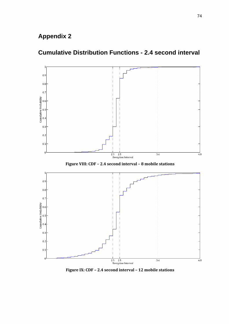
74
Appendix 2
Cumulative Distribution Functions - 2.4 second interval
Figure VIII: CDF – 2.4 second interval – 8 mobile stations
Figure IX: CDF – 2.4 second interval – 12 mobile stations
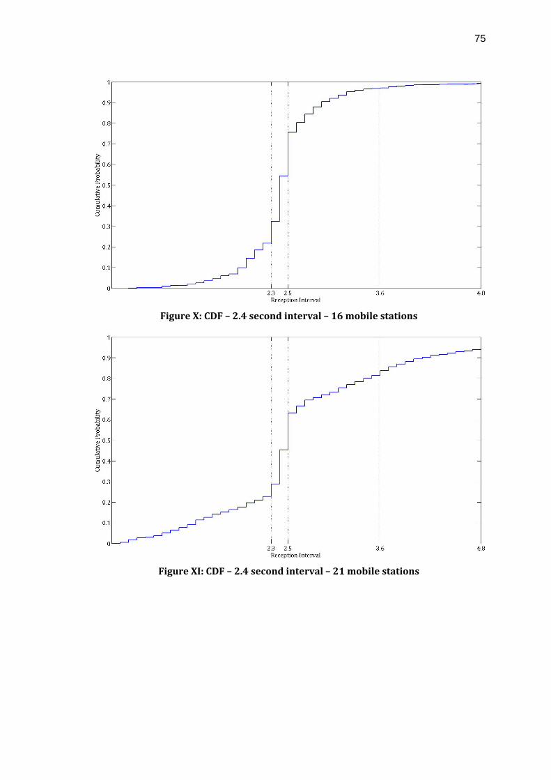
75
Figure X: CDF – 2.4 second interval – 16 mobile stations
Figure XI: CDF – 2.4 second interval – 21 mobile stations