Embed Size (px)
Citation preview

Advantages at a glance
· A proven implant attachment system
· Corrects implant divergences
· Fits on every VARIOmulti abutment
· Easy assembly
LOCATOR® abutment and collar for VARIOmulti
INFO

3 mm
Fo
_0
2d
20
2.0
0
0
6/1
4c
an
ari
ni
co
mm
un
ica
tio
ns
The LOCATOR abutment and collar can be used with straight and angled
(17° and 30°) VARIOmulti abutments.
The 3 mm wide collar is screwed directly onto the VARIOmulti abutment
using the LOCATOR component.
The new collar and LOCATOR attachment in combination with angled
VARIOmulti abutments allows the clinician to compensate for greater
implant divergences. The direction of insertion is then optimized for over-
dentures and denture fi t is better controlled, ultimately allowing for easier
attachment and removal of the denture by the patient. The collar and
LOCATOR combination also offers new temporary restoration possibili-
ties on VARIOmulti abutments.
Limitations to use
· Use with VARIOmulti abutments PF � 3.5 mm is contraindicated.
· Not appropriate where a totally rigid connection is required.
Use
Attach the VARIOmulti abutment on the implant with the appropriate fi nal
torque. Affi x the LOCATOR insert for hand piece (Art. no. 8913 or 8914) in
the dental coupling of the short MONO insertion device.
With the MONO insertion device and MONO torque ratchet, tighten the
LOCATOR abutment and collar on the VARIOmulti abutment to a torque
of 20 Ncm.
LOCATOR® abutment and collar for VARIOmulti2 sets per pack2 sets per pack
8909-2
LOCATOR® insert, for hand piece and for short MONO insertion
device,device, stainless steelstainless steel
Length
23.0 mm 8913
29.0 mm 8914
MONO insertion device,MONO insertion device, stainless steel/PEEK stainless steel/PEEK
short *
Length 15.4 mm
3.03.162
* All latch-type instruments can be utilized with the MONO insertion
device, short.
MONO torque ratchet,MONO torque ratchet, titanium alloytitanium alloy
Length
110.0 mm 3.03.160
ZEST LOCATOR® abutment and collar for VARIOmulti

SWISS PRECISION AND INNOVATION. SWISS PRECISION AND INNOVATION.
LOCATOR®
Implant attachment system

2 © Thommen Medical
Notes
EXPLANATION OF SYMBOLS
Batch code
Use by date
Date of manufacture
Sterilized using irradiation
Sterilized using ethylene oxide
Sterilized using steam or dry heat
Temperature limitation
Do not re-use
Non-sterile
Caution
Article number
Conformity symbol as specified by EU Directive MDD 93/42/EEC
Consult instructions for use
Do not resterilize
Do not use if package is damaged
Atmospheric pressure limitation
Manufacturer
Keep away from sunlight
May only be sold to and prescribed byphysicians (USA)
COLOR CODE Each implant platform dia meter has
a color code, which can be found on all implant packs,
on the impression items and on most diameter-specifi c
instruments.
Yellow = platform 3.5 mm
Green = platform 4.0 mm
Blue = platform 4.5 mm
Grey = platform 5.0 mm
Violet = platform 6.0 mm
RESPONSIBILITY/LIABILITY As part of an overall scheme, Thommen
implants may be used only with the ori ginal components and instruments in
accordance with the manufacturer’s instructions. The use of unapproved com-
ponents from other systems can cause malfunctioning of the implants and
abutments and lead to implant failure. The use of the product is the responsibility
of the user and, as such, beyond the control of Thommen Medical AG. We
refuse to accept any re sponsibility or liability for any damage due to incorrect
utilization of the product.
Products labeled “Do not re-use” may not be refurbished and/or reused. The
refurbishment and/or reuse of these products can affect their function (fi tting
and/or cutting properties) as well as their safe use (risk of infection, disease
transmission, fading of the laser or color marks, corrosion). Detailed information
about the possible conse quences, which may result from negligence to follow
this information, is avail able from your dealer. Caution: Federal law (USA)
restricts this device to sale by or on the order of a dentist or physician.
GUARANTEE OF STERILITY OF STERILE PRODUCTS Products of the
Thommen Implant System supplied in sterile packaging must not be resterilized.
If the sterile packaging is damaged during transport or storage, the product
must not be used. Products that have been opened and have not been imme-
diately used for the intended operation must not be used thereafter. After
resterilization, the safety, function and effi cacy of the product cannot be guaran-
teed by the man ufacturer.
STORAGE Please note the specifi cations on all labels and package leafl ets
regarding transportation, storage and instructions for use.
INSTRUCTIONS FOR USE The following information is not intended as com-
prehensive for the Thommen Implant System. New customers are advised to
undergo training by a specialist experienced in the use of this system.
VALIDITY This product catalogue replaces all previous editions.
PRODUCT DOCUMENTATION You can fi nd detailed information on the
han dling of Thommen implants in our brochures. Ask our national representa-
tives for product brochures and instructions for use.
AVAILABILITY NOTE Not all products shown in this brochure are available in
all countries. For further information please contact our subsidiary or distributor
in your country.
COPYRIGHT©/REGISTERED® SPI®, INICELL®, APLIQUIQ® and Remotis® are
registered trademarks of Thommen Medical AG. Publication or reproduction is
permitted only with the written consent of Thommen Medical AG. LOCATOR® is
a registered trademark of Zest Anchors Inc., CA, USA.
COLORED WARNING STICKER
Application was changed – follow the instructions in the corresponding docu-
mentation.
New design – the application has not been changed.

© Thommen Medical 3
LOCATOR®
Implant attachment system 4
Placement of the LOCATOR® abutment 6
Determining the angulation 7
LOCATOR® male replacement by the dentist 8
LOCATOR® male replacement by the dental technician 12
How to change the LOCATOR® male replacement 14
Reline and rebase 16
Product overview 18
Contents

4 © Thommen Medical
LOCATOR®
Implant attachment system
Advantages at a glance
· Lowest vertical height
· Locating design
· Retention inside and out
· Rotational pivoting action
· Suitable for non-parallel implants
The LOCATOR® implant attachment system is available for Thommen im-
plants with platform 3.5 mm and major.

© Thommen Medical 5
The total height of the LOCATOR® attachment (abutment plus LOCATOR®
cap incl. male replacement) is only 3.5 mm on an Thommen implant making
it ideal for cases with limited vertical space.
The self-locating design allows a patient to easily seat their overdenture
without the need for accurate alignment of the attachment components.
The patented Dual Retention innovation provides the LOCATOR® attach-
ment with greater retention surface area than ever before available with
other attachments. The LOCATOR® attachment provides both internal and
external retention to securely hold the overdenture in place.
The design of the pivoting LOCATOR® male allows a resilient connection for
the prosthesis without any resulting loss of retention. Throughout its range
of movement, the nylon male remains in contact with the LOCATOR® abut-
ment.
The LOCATOR® male replacements can be used to restore an implant with
up to 10 degrees of divergence (20 degrees between implants). The
LOCATOR® extended range male replacements can accommodate a diver-
gence between 10 and 20 degrees (40 degrees between implants).
Indications
The LOCATOR® attachment system is designed for use with overdentures
or partial dentures retained in whole or in part by endosseous implants in the
mandible or maxilla.
Contraindications
The LOCATOR® attachment system is not appropriate where a totally rigid
connection is required. Use on a single implant with divergence of greater
than 20 degrees is not recommended.
Sterilization
All components and instruments are supplied non-sterile. Abutments and
metal instruments should be cleaned and autoclaved before use.
This document contains the most current instructions for use.

6 © Thommen Medical
1. To select the proper LOCATOR® abutment, determine the diameter
of implant being used. Then measure the tissue thickness from the
apical rim of the implant body to the crest of the gingiva at the high-
est side of the implant site. Select the corresponding LOCATOR®
abutment tissue cuff height that exactly equals the tissue measure-
ment, or is the next closest higher size available. The exact tissue
cuff height of LOCATOR® abutment will position the proper 1.5 mm
of working attachment above the surrounding gingival level (the
working attachment should not be submerged below the tissue).
2. The MONO insertion device, short (art. no. 3.03.162), has an internal
dental latch which fits with the “LOCATOR® insert, for handpiece and
for short MONO insertion device” (no. 8913 or 8914).
3. Attach the LOCATOR® insert to the MONO insertion device, short,
and use it to hand tighten the LOCATOR® abutment. Then torque
the LOCATOR® abutments using the MONO torque ratchet. The final
torque for LOCATOR Abutments PF 3.5 mm is 20 Ncm; the final
torque for PF 4.0-6.0 mm is 30 Ncm.
Note
It is recommended that any LOCATOR® implant abutment gets
checked at future recall appointments to ensure that appropriate
torque value is maintained.
* symbolic illustration
Placement of the LOCATOR® abutment
*
*

© Thommen Medical 7
1. Determine the angulation of the LOCATOR® abutment by attaching
a LOCATOR® parallel post (art. no. 8517) to it and measuring the an-
gle with the LOCATOR® angle measurement guide (art. no. 9530).
2. Select the final LOCATOR® male replacement retention liner based
upon the determined angle measurement of each implant. If the di-
vergence of an implant is less than 10 degrees, use one of the
LOCATOR® male replacements (clear = 5 lbs, pink = 3 lbs, and blue
= 1.5 lbs). If the divergence of any implant is between 10 degrees and
20 degrees, then use one of the extended range male replace-
ments (green1 = 4 – 3 lbs, orange = 2 lbs. and red = 0.5 lbs) which can
accommodate a divergence up to 20 degrees (40 degrees be-
tween implants).
1 The retention value is dependent upon the degree of angulation; at
10 degrees the retention would be 4.0 pounds and at 20 degrees
the retention would be approximately 3.0 pounds.
3. Follow the steps in section, “LOCATOR® male replacement by the
dentist”, or the steps in section, “LOCATOR® male replacement by
the laboratory”.
* symbolic illustration
Determining the angulation
*

8 © Thommen Medical
1. Insertion of the proper LOCATOR® abutment at tissue level must be
completed (see page 6 “placement of the LOCATOR® abutment”)
before beginning the procedure for placement of the LOCATOR®
male.
2. Place a white block-out spacer (art. no. 8514 and included within the
package of art. no. 8519-2) over the head of each LOCATOR®
abutment. The spacer is used to block out the area immediately sur-
rounding the abutment. The space created will allow the full resilient
function of the pivoting LOCATOR® cap over the LOCATOR® male.
Note
If the white block-out spacer does not completely fill the space be-
tween the tissue and the LOCATOR® cap, it is necessary to block out
any remaining undercuts to prevent the added acrylic resin from
locking the denture onto the abutment. This can be accomplished
by stacking more block-out spacers.
3. Insert a LOCATOR® cap with black processing male (part of the
LOCATOR® male processing package, art. no. 8519-2 package or
separate as a package with 20 pieces, art. no. 8515-20) into each
LOCATOR® abutment, leaving the white block-out spacer beneath
it. The black processing male will maintain the overdenture in the up-
per limit of its vertical range of movement during the processing pro-
cedure.
4. Prepare a recess in the denture to accommodate the protruding
LOCATOR® male. There must be no contact between the denture
and the LOCATOR® cap. If the denture rests on the LOCATOR® cap
excess pressure on the implant will result.
* symbolic illustration
LOCATOR® malereplacement by the dentist
Dentist
*
*

© Thommen Medical 9
5. Use a light-cure acrylic or mix a permanent self-curing acrylic to
cure/bond the LOCATOR® cap into the denture. Place a small
amount of material in the recess of the denture and around the
LOCATOR® cap of the processing male.
6. Insert the denture into position in the oral cavity. Guide the patient
into occlusion, maintaining a proper relationship with the opposing
arch. Maintain the denture in a passive condition, and prevent
any movement of the denture, while the acrylic sets. Excessive
occlusal pressure during the setting time may cause tissue re-
coil against the denture base and could contribute to dislodging
and wear of the nylon males.
7. After the acrylic resin has cured, remove the denture and discard
the white spacer. Use a burr to remove excess acrylic, and polish
the denture base before selecting and installing the appropriate re-
silient nylon male based upon number of implants and patient’s
preference for retention.

10 © Thommen Medical
8. Use part A of the LOCATOR® core tool (art. no. 8393) to remove the
black processing male from the LOCATOR® cap.
Part A is released from the centre of part B with two full turns
counter clockwise, such that a gap is visible in between.
To remove a LOCATOR® male replacement from the titanium metal
housing – simply insert the tip (part A of the LOCATOR® core tool)
into cap/male assembly and push straight in. The sharp edge of the
tip will grab hold of the nylon male and allow you to pull it straight out
of the cap.
To discard the nylon male from the tip (part A of the LOCATOR® core
tool) on the core tool – just tighten the tip clockwise back onto the
core tool – this will activate the removal pin and dislodge the nylon
male from the tip end.
A
B
B
A
B
A

© Thommen Medical 11
9. Part B of the LOCATOR® core tool (art. no. 8393) is used to firmly
push a LOCATOR® male replacement into the LOCATOR® cap. The
male replacement must seat securely into place, level with the rim of
the cap.
Note
Do not use Part A of the LOCATOR® core tool to install new male
replacements: this will destroy them.
The male replacement will not stay on the tool when it is turned up-
side down due to varying retention values of male replacements
available. It is best to hold the denture with the base side down and
snap the male into the LOCATOR® cap.
10. Instruct the patient in the path of insertion. Have the patient insert
and remove the appliance several times.

12 © Thommen Medical
1. Insertion of the proper LOCATOR® abutment at tissue level must be
completed (see page 6 “placement of the LOCATOR® abutment”)
before beginning the following impression procedure.
Note
The impression must be made with an elastomer impression mate-
rial (polyvinylsiloxane or polyether rubber). Hydrocolloids are not
suitable for this application.
2. Place a LOCATOR® impression coping (art. no. 8505) with black pro-
cessing male onto each LOCATOR® abutment.
Note
An alternative reline impression technique using the patient’s pros-
thesis is possible with use of the LOCATOR® black processing male
(part of the LOCATOR® male processing package, art. no. 8519-2
package or separate as a package with 20 pieces, art. no. 8515-20).
When the impression is withdrawn, the processing male will remain
on the abutment. Remove the processing male from each abut-
ment and snap it onto a LOCATOR® female analog. Reposition this
assembly back into the impression (LOCATOR® cap) making sure it
is fully seated. Pour the master cast.
3. Insert LOCATOR® analogs into each impression coping and pour the
master cast. Upon separation, the LOCATOR® analog is a part of the
master cast replicating the position of the LOCATOR® abutment in
the oral cavity.
4. Before waxing and processing the appliance, place white block-out
spacers and LOCATOR® caps with black processing male on each
analog. Make sure the male is fully seated.
* symbolic illustration
LOCATOR® male replacementby the dental technician
Dental technician
*
*

© Thommen Medical 13
5. Set the teeth and wax the appliance. Proceed with the processing
technique of your choice through the boil-out step.
6. After the boil-out, remove the processing male. Place a white block-
out spacer over the head of each analog. The spacer is used to
block out the immediate area surrounding the LOCATOR® abut-
ment. The space created will allow the full resilient function of the piv-
oting LOCATOR® cap over the LOCATOR® male.
7. Reinsert the LOCATOR® black processing male into each analog,
leaving the white block-out spacer beneath it. The black processing
male will maintain the overdenture in the upper limit of its vertical re-
siliency during the processing procedure.
8. Complete the processing and discard the white block-out spacer.
Avoid damage to the final male by polishing the denture base before
changing to the final male.
Use part A of the LOCATOR® core tool (art. no. 8393) to remove the
black processing male from the LOCATOR® cap (see page 14, “How
to change the LOCATOR® male”).
9. The prosthesis is polished without the final replacement male
inserted. Soiling and damage to the final male replacement is thus
avoided.
10. Part B of the LOCATOR® core tool (art. no. 8393) is used to firmly
push a LOCATOR® male replacement into the LOCATOR® cap. The
male replacement must seat securely into place, level with the rim of
the cap (see page 14, “How to change the LOCATOR® male”).
Note
The male replacement will not stay on the tool when it is turned up-
side down due to the varying sizes of males available. It is best to
hold the denture with the base side down and snap the male into the
LOCATOR® cap.

14 © Thommen Medical
1. The LOCATOR® core tool (art. no. 8393), which contains a part A for
the male removal and a part B for the male seating, is used to re-
move the nylon male from the LOCATOR® cap and replace it with
another LOCATOR® male replacement.
Part A is released from the centre of part B with two full turns
counter clockwise, such that a gap is visible in between.
To remove a LOCATOR® male replacement from the titanium metal
housing – simply insert the tip (part A of the LOCATOR® core tool)
into cap/male assembly and push straight in. The sharp edge of the
tip will grab hold of the nylon male and allow you to pull it straight out
of the cap.
To discard the nylon male from the tip (part A of the LOCATOR® core
tool) on the core tool – just tighten the tip clockwise back onto the
core tool – this will activate the removal pin and dislodge the nylon
male from the tip end.
How to change the LOCATOR® male replacement
A
B
B
A
B
A
© Thommen Medical 15
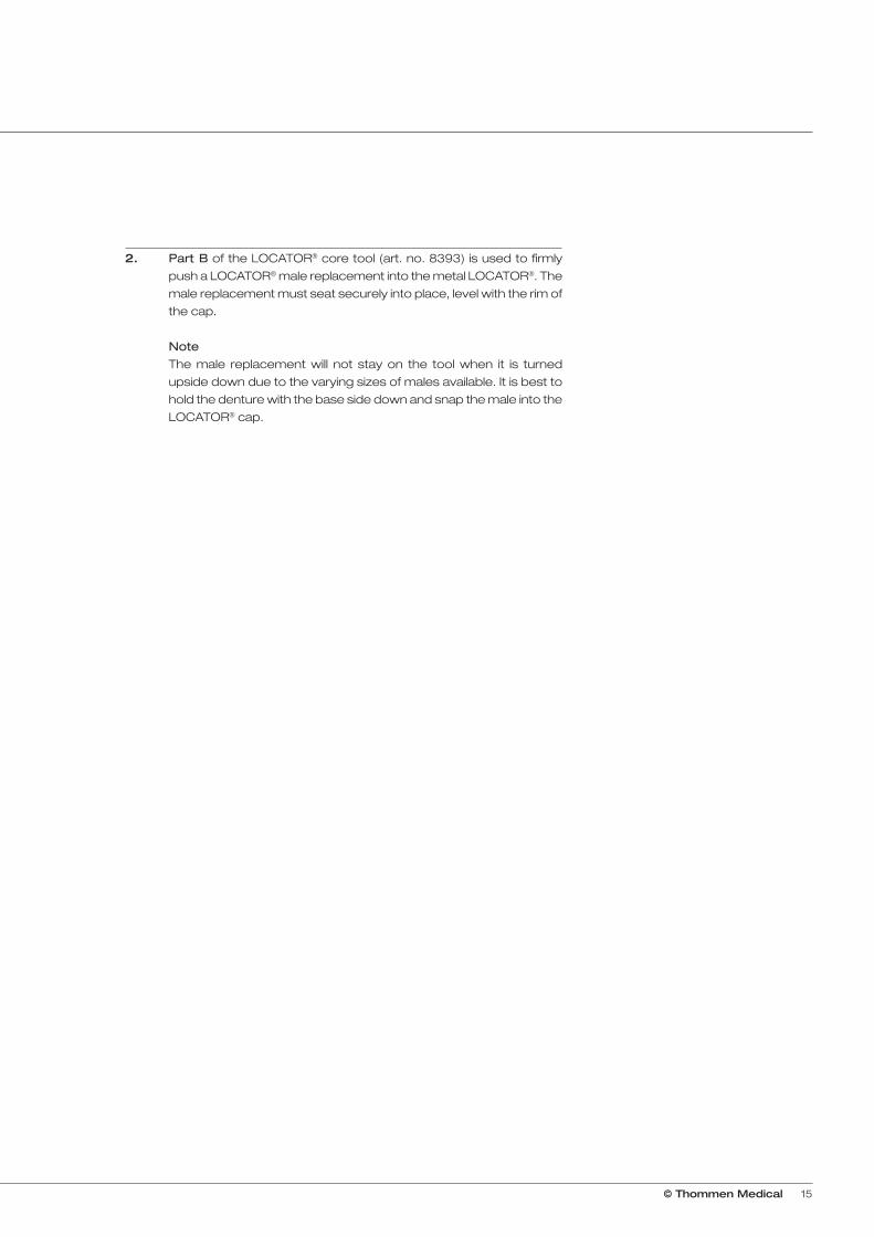
2. Part B of the LOCATOR® core tool (art. no. 8393) is used to firmly
push a LOCATOR® male replacement into the metal LOCATOR®. The
male replacement must seat securely into place, level with the rim of
the cap.
Note
The male replacement will not stay on the tool when it is turned
upside down due to the varying sizes of males available. It is best to
hold the denture with the base side down and snap the male into the
LOCATOR® cap.

16 © Thommen Medical
1. Remove each existing nylon male from its LOCATOR® cap following
the steps in “how to change the LOCATOR® male”. Replace them
with black processing male replacements. The built-in spacer of the
black processing male will maintain the overdenture in its upper level
of vertical resiliency during the reline process.
2. Take a reline impression using the existing overdenture as a tray. The
black processing males will engage the LOCATOR® abutments and
hold the prosthesis in place while the impression material sets.
3. When the impression is withdrawn, the black processing male
replacements will remain in the LOCATOR® caps.
4. Snap a LOCATOR® analog (art. no. 8516, 5.0 mm, or art. no. 8530,
4.0 mm) onto each black processing male and pour a master
model.
Reline and rebase

© Thommen Medical 17
5. After processing the reline and polishing the denture base, replace
the black processing males with the final LOCATOR® male replace-
ments.

18 © Thommen Medical
Product overview
PF 3.5 mm PF 4.0 mm PF 4.5 mm PF 5.0 mm PF 6.0 mm
LOCATOR® abutment, Titanium alloy
Collar height
0.73 mm 8875
1.0 mm 8461 8786 8792 8881
2.0 mm 8876 8462 8787 8793 8882
3.0 mm 8877 8463 8788 8794 8883
4.0 mm 8878 8464 8789 8795 8884
5.0 mm 8465 8790 8796
6.0 mm 8466 8791 8797
LOCATOR® male processing package, Quantity per pack: 2 sets, Titanium/Nylon
8519-2
The set contains
· 1 LOCATOR® cap with male processing, black (8515-20)· 1 LOCATOR® block-out spacer (8514)· 1 LOCATOR® male replacement, clear (8524)
· 1 LOCATOR® male replacement, pink (8527)
· 1 LOCATOR® male replacement, blue (8529)
LOCATOR® male processing package, for extended rangeQuantity per pack: 2 sets, Titanium/Nylon
8540-2
The set contains
· 1 LOCATOR® cap with male processing, black (8515-20)· 1 LOCATOR® block-out spacer (8514)· 1 LOCATOR® male replacement green (8547)
· 1 LOCATOR® male replacement orange (8915)
· 1 LOCATOR® male replacement red (8548)
LOCATOR® male replacement, 4 pieces, Nylon
Retention value Color
5 lbs. clear 8524
light 3 lbs. pink 8527
extra light 1.5 lbs. blue 8529
LOCATOR® male replacement, for extended range, 4 pieces, Nylon
Retention value Color
4–3 lbs. green 8547
light 2 lbs. orange 8915
extra light 0.5 lbs. red 8548

© Thommen Medical 19
LOCATOR® core tool, Stainless steel
8393
LOCATOR® impression coping, 4 pieces, Aluminum/LDPE
8505
LOCATOR® analog, 4 pieces, Aluminum
4.0 mm 8530
5.0 mm 8516
LOCATOR® parallel post, 4 pieces, LDPE
8517
LOCATOR® angle measurement guide, Stainless steel
Width Height
50.0 mm 15.0 mm 9530
LOCATOR® male processing, black, 20 pieces, Nylon
8515-20
LOCATOR® block-out spacer, 20 pieces, Teflon®
8514
LOCATOR® insert, for handpiece and for short MONO insertion device, Stainless steel
Length
23.0 mm 8913
29.0 mm 8914

SWISS PRECISION AND INNOVATION. SWISS PRECISION AND INNOVATION. www.thommenmedical.com
Headquarters
Subsidiaries/National Distributors
Austria
Benelux
Canada
China
Finland
France
Germany
Italy
Japan
Middle East
Poland
South Korea
Spain/Portugal
Switzerland
Taiwan
USA
1250
Fo
_0
2d
111.
05
01/
14c
an
ari
ni
co
mm
un
ica
tio
ns


![Internal - Luciano Chinellato · AnyOne® Internal è -P_[\YL 3L]LS 7YVZ[OLZPZ EZ Post Milling Abutment Angled Abutment CCM Abutment Temporary Abutment [Titanium] Temporary Abutment](https://img.pdfslide.net/doc/110x75/5c038f7909d3f2156d8cd7fd/internal-luciano-anyone-internal-e-pyl-3lls-7yvzolzpz-ez-post-milling.jpg)