Embed Size (px)
Citation preview

Control Solutions
LOCC-BoxLUTZE Overload Current Control
Intelligent DC Control Circuit Protection


Efficiency in Automation - A reflection of our company philosophy
As an experienced specialist in automation technology,with solutions for flexible and high flexing cables, cableassemblies, interfaces, current control and cabinet wiring,we have had a focus on efficiency for many years.
LUTZE defines Efficiency in Automation field as theuse of sustainable products and solutions to furtherincrease the performance of our products in our customers applications.
We realise this by using components for highly efficientcontrol systems, products with above average life cyclesand raising energy efficiency in control cabinets bymeans of the LSC wiring system.
Efficiency in Automation reflects our efforts in striving for efficient working relationships with our customers: in a medium sized family owned company we have short communcation channels and a high level of manufacturing competence.
The value of a product or a solution from LUTZE is determined by its sustainable qualities. Every innovationwill only be successful in the future if it has a long termpositive effect. Therefore, we provide long lasting as well as highly efficient components.
Thus LUTZE creates value through efficiency. LUTZEprovides answers and demonstrates how to handleresources responsibly, with our environment and ourfuture in mind. LUTZE - Efficiency in Automation
For more information on our solutions, please visit www.lutze.com
Welcome to LUTZE
Cable Solutions
Connectivity Solutions
Cabinet Solutions
Control Solutions
Transportation Solutions

Business Management: Sustainable and forw a
The future is blue
Sustainable enterprise means thinking and planning ahead,understanding and embedding the belief that long lasting successis more important than short-termprofit maximisation.
This is an attitude that has existedwithin LÜTZE for quite some time.Economic and environmentalresponsibilities complement eachother well and are reflected in thesustainable management and
product policy - and from now inthe SkyBLUE campaign.
We manufacture our products in aresourceful and energy-consciousmanner. We use long lasting,environmentally-friendly materials.And our products, in turn, helpour customers save energy andresources. Good for everyone: for us, for theenvironment, for our customers awin-win-win situation.

: w ard-looking
Goods with real value
The value of a product or a solutionfrom LÜTZE is determined by itssustainable qualities as well. Everyinnovation is only as successful inthe future if it has a long-term positi-ve effect. Therefore, we providelong lasting as well as highly effi-cient components. We are incorporating the necessaryknowledge and manufacturing competence in numerous joint projects with the objective of improving energy efficiency and
sustainable technologies and industries. Thus, LÜTZE providesanswers and demonstrates how tohandle resources responsibly, withour environment and our future in mind.
„The competitiveness of our industry and of its suppliers depends quite sub-stantially on how we succeed in developing practical results. The results thatwe produce together today, are our competitive advantages in the future.“ Udo Lütze, Member of the Executive Committee of the Green Carbody Innovation Alliance

Reliable protection of DC 24V circuits
Intelligent safeguarding of selectivity
Primary switching controllers and automaticpower units nowadays form the basis of theDC 24V supply level. Due to the operatingbehaviour of those devices, the specifiedselective protection of individual circuits,especially in case of overcurrent, is virtuallyunfeasible. A complete system shutdown isinevitable.
Operating behaviour of primary switchingcontrollers
Switched-mode power supplies and theircomponents are rated for a specific nominalvalue and run hot under higher load. To protect against self-destructing, they shutdown at between 1.1 and 2.5 times the nominal current, according to type. Manydevices feature Hiccup mode, which switchesoff in case of overload and automaticallyswitches back on after a short time. If theoverload persists, the process repeats untilthe fault is manually rectified. This means a fuse is never tripped. Using devices with a forward characteristic does not deliver success either. The power supply does notswitch off, but supplies only a 1.1 to 1.2 timeshigher output current when the output voltageis reduced. This characteristic likewise doesnot trip an automatic circuit-breaker, or if itdoes, then only in the hours range.Furthermore, both output modes have the disadvantage that loads such as DC motorsor capacitive consumers cannot be started. At additional cost, operation of heavy loadscan be achieved in the simplest case byusing a device with a higher output power ora device with integrated power boost.
In this, the device with power boost continuously supplies 1.2 to 1.3 times thenominal current in the temperature range upto +45°C. On reducing the output voltage, amaximum of 2.5 times the nominal current isreached which - dependent on the deviceitself and the characteristic of the automaticcircuit-breaker - may be just enough to effecta shutdown.
Characteristics of automatic circuit-breakers
The trip curve of an automatic circuit-breakerwith characteristic B (Figure 1) is consideredby way of example. To record smaller over-currents, a thermal trip in the minutes tohours range is used (hold >1h at I = 1.13 xInom and trip <1h at I = 1.45 x Inom). Switch-off in case of high overcurrents is effected byimmediate magnetic tripping within 0.01 to 0.1 seconds. If such a device is used in conjunction with a 10A switched-mode powersupply, the switch-off occurs at 1.2 times thenominal current only after 20 to 60 minutes.Even at 2.5 times nominal current (powerboost) between 25 seconds and two minuteselapse until switch-off in the thermal range. In short: essential protection - in particularselective protection of connected devices - isnot provided. The fuse essentially performs adummy function. In the event of a short-circuitor faulty wire supply would be maintained at2.5 times nominal current. System failure oreven a cable fire may be the consequence.
Current Control System · Basics
Selective switch-off
Selective load protection means that in caseof overload or short-circuit only the faulty current path is switched off, with no reactiveeffect on the supply. The standards EN60204-1 (line protection and fire prevention) and EN 61131-1 and -2 (operatingstates and storage) are also applicable to therating of the overcurrent protection device inDC 24V circuits. In concrete terms, thismeans withstanding a mains power failurelasting 10ms without functional impairment,which demands the deployment of large input capacities. Furthermore, hazardousovercurrents must be reduced to a safe levelwithin 5s. Rating is made more difficult by the fact that nowadays many parallel con-sumers are supplied by way of one protectionelement.
LÜTZE LOCC-Box – the intelligent currentmonitoring system
Figure 2: LOCC-Box single module
The ideal solution would be one which iscapable of optimally operating capacitiveloads to start heavy loads and quickly detect-ing an overcurrent in operation and switchingoff only the affected path. Such a systemshould of course store the fault so as to prevent danger from switching back on andpermit diagnosis. The Lutze LOCC-Box system meets those requirements in a modu-lar design with additional intelligent functions.To meet the widely varying demands onswitch-off response, the LOCC-Box systemfeatures the facility to program 10 differentcharacteristics by way of a switch. Both standard automatic unit characteristics and in particular custom characteristics can beimplemented. The nominal current range canadditionally be selected with locking settingsfrom 1A to 10A. The adjustable current rangeand characteristic is very important whenretrofitting, as in such cases the device protection often has to be modified andadapted. As additional information, the capacity utilisation of the path is indicated by an LED. When 90% of the programmedcurrent value is reached the status LED startsto flash. In the event of a switch-off due toovercurrent or short-circuit, in addition to thevisual indication by a red LED.
6

7
A 24V signal is set as a collective fault warning. This eliminates the need to installand wire additional auxiliary contacts. Arestart after clearing the fault is then effectedeither using the mechanical switch on thedevice or from the main system by remotecontrol. This channel-based switching facilityis of great importance in particular in the commissioning phase of a system, as itenables individual system components to beactivated and checked specifically.
LOCC-BoxPractical and efficient
The monitoring function itself is one side ofthe coin. The other in many other systems is the associated mechanism. Frequentlymulti-channel solutions are offered on themarket which only make sense if exactly the
available channels are required. If that is notthe case, or if only one channel has to beadditionally implemented subsequently,money and space will be wasted. Another disadvantage of this solution is the looping of up to 40A via a printed circuit board. Thisentails an enormous load on the carrier material and interruption of the entire supplywhen a device is replaced. What in otherareas of automation has been state of the artfor over 10 years is also ideal here as thesolution in a highly modular configuration!
Here, too, the LOCC-Box system is settingnew standards. The single-channel designwith all the functionality described offers thehighest possible flexibility. As shown below,customers can decide whether the supply isprovided by each module individually or viathe system supply (infeed terminal, copper
Current Control System · Basics
rail, end terminal). The particular advantageof this method of infeed is the screwless contact carriage, which permits exchanging of individual channels in operation withoutinterrupting the entire supply. This additionalprovides functionality to switch off individualpaths to perform essential work safely. Themaximum supply current is dictated by the6mm2 terminal, and is DC 40A. The slim width of just 8.1mm results in an installedwidth of just 340mm even with a 40-channelconfiguration. The system housing is comple-mented by name plate labels, seals and ajumper system to loop signals.
Standard Applicationwithout supply set, art. no. 716425 with supply set, art. no. 716425
Individual construction withdistance terminal
Empty housing as placeholder
The supply voltage is fed direct tospring terminal 6
DC 12/24 V: terminal 60 V (reference): terminal 5
The distance terminalArt. no. 716422 is used as a spacer or as isolation. Supply via spring terminal 6.
The empty casing, without contacts art. no. 716424, can be used as a placeholder for futureenhancements.
The supply voltage is fed via the supply terminals
0 V (reference): terminal 5
DC 12/24 V
Dual supply left Additional supplyin the middle
Additional supply right oroutlet to next block
Art. no.716421
Art. no.716425
DC 12/24 V
Jumper comb (white)
Art. no.716425
DC 24 V
DC 12/24 V
DC 12/24 V
DC 12/24 V
next block
DC 12/24 V
Use with additional supply terminalsSupply set, art. no. 716425 andsupply terminal, art. no. 716421
The supply terminal is accessed via an aperture in theleft hand side wall. This enables a variable positioningin the system construction. The maximum total currentcan thus be increased. Max. 160 A / 4 feeds.

5, 6
8
LCOS-CC • Application examples
*Option with fieldbus – Design on request.
e.g. Switching power supply 722814 DC 24 V, 100 A.
Controlled Powerslots, max. 32 *
Controlled Powerslots, max. 32 *
Direct supply
Data bus *

9
Standard Applicationwith supply set, art. no. 716425
LoadConsumer
Application of the0 V Collectiveterminalwith supply setArt. no. 716425
PIN no. 1 1 1 1 1 1 1 1 1 1 1 1
PIN-Nr. 5, 6
5, 6
1-4
1-4
e.g. Switching power supply 722814 DC 24 V, 100 A.
LOCC-Box / LOCC-Box-Net • Application examples

Adjustable rated current(1 A...10 A in 1 A Steps)
Adjustable characteristic (fast- … slow acting)
“Power-ON”-effectto switch on capacitive loads
Single or centralized fault indication
Last status memorization
Spring terminals
Small device – width 8,1mm
Response time independent of temperature
Contact slots for each potential usablefor jumper combs
Solid state relay with current controlswitching frequency up to 1 kHz
Contact slots for each potential usable forjumper combs
Modular, flexible and safe: LOCCThe intelligent LÜTZE Overload
Control Solutions

CC-Box / LOCC-Box-NetCurrent Control System
Remote ON / OFF
Manual ON / OFF
Status indication “operation”, “fault”,“90 % load” and “100 % load”
Adjustment cover accommodates lock out tags
Flammability class UL-94-V0; NFF I2,F2
Power distribution via direct supply or supply set
Optional remote Gateway interface
UL 508 Listed
The picture shows 5 x LOCC-Box incl. supply set
12
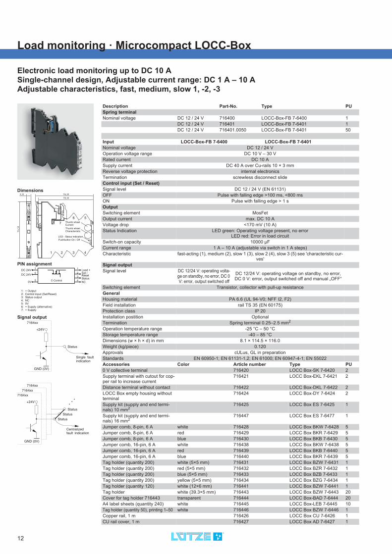
Load monitoring · Microcompact LOCC-Box
Electronic load monitoring up to DC 10 ASingle-channel design, Adjustable current range: DC 1 A – 10 AAdjustable characteristics, fast, medium, slow 1, -2, -3
Dimensions
PIN assignment
Signal output
7DC 24V
C-Control
6
50V
3
1Load +
Status4
NC
DC 24V2 Set /
Reset
1: + Output2: Control input (Set/Reset)3: Status output4: NC5: 0V6: + Supply (alternative)7: + Supply
Description Part-No. Type PUSpring terminalNominal voltage DC 12 / 24 V 716400 LOCC-Box-FB 7-6400 1
DC 12 / 24 V 716401 LOCC-Box-FB 7-6401 1DC 12 / 24 V 716401.0050 LOCC-Box-FB 7-6401 50
Input LOCC-Box-FB 7-6400 LOCC-Box-FB 7-6401Nominal voltage DC 12 / 24 VOperation voltage range DC 10 V – 30 VRated current DC 10 ASupply current DC 40 A over Cu-rails 10 × 3 mmReverse voltage protection internal electronicsTermination screwless disconnect slideControl input (Set / Reset)Signal level DC 12 / 24 V (EN 61131)OFF Pulse with falling edge >100 ms, <800 msON Pulse with falling edge > 1 sOutputSwitching element MosFetOutput current max. DC 10 AVoltage drop <170 mV (10 A)Status Indication LED green: Operating voltage present, no error
LED red: Error in load circuitSwitch-on capacity 10000 μFCurrent range 1 A – 10 A (adjustable via switch in 1 A steps)Characteristic fast-acting (1), medium (2), slow 1 (3), slow 2 (4), slow 3 (5) see 'characteristic cur-
ves'Signal outputSignal level DC 12/24 V: operating volta-
ge on standby, no error, DC 0 V: error, output switched off
DC 12/24 V: operating voltage on standby, no error, DC 0 V: error, output switched off and manual „OFF“
Switching element Transistor, collector with pull-up resistanceGeneralHousing material PA 6.6 (UL 94-V0; NFF I2, F2)Field installation rail TS 35 (EN 60175)Protection class IP 20Installation postition OptionalTermination Spring terminal 0.25–2.5 mm2
Operation temperature range -25 °C – 50 °CStorage temperature range -40 – 85 °CDimensions (w × h × d) in mm 8.1 × 114.5 × 116.0Weight (kg/piece) 0.120Approvals cULus, GL in preparationStandards EN 60950-1; EN 61131-1,2; EN 61000; EN 60947-4-1; EN 55022Accessories Color Article number Type PU0 V collective terminal 716420 LOCC Box-SK 7-6420 2Supply terminal with cutout for cop-per rail to increase current
716421 LOCC Box-EKL 7-6421 2
Distance terminal without contact 716422 LOCC Box-DKL 7-6422 2LOCC Box empty housing without terminal
716424 LOCC Box-DY 7-6424 2
Supply kit (supply and end termi-nals) 10 mm2
716425 LOCC Box ES 7-6425 1
Supply kit (supply and end termi-nals) 16 mm2
716447 LOCC Box ES 7-6477 1
Jumper comb, 8-pin, 6 A white 716428 LOCC Box BKW 7-6428 5Jumper comb, 8-pin, 6 A red 716429 LOCC Box BKR 7-6429 5Jumper comb, 8-pin, 6 A blue 716430 LOCC Box BKB 7-6430 5Jumper comb, 16-pin, 6 A white 716438 LOCC Box BKW 7-6438 5Jumper comb, 16-pin, 6 A red 716439 LOCC Box BKB 7-6440 5Jumper comb, 16-pin, 6 A blue 716440 LOCC Box BKR 7-6439 5Tag holder (quantity 200) white (5×5 mm) 716431 LOCC Box BZW 7-6431 1Tag holder (quantity 200) red (5×5 mm) 716432 LOCC Box BZR 7-6432 1Tag holder (quantity 200) blue (5×5 mm) 716433 LOCC Box BZB 7-6433 1Tag holder (quantity 200) yellow (5×5 mm) 716434 LOCC Box BZG 7-6434 1Tag holder (quantity 120) white (12×6 mm) 716441 LOCC Box BZW 7-6441 1Tag holder white (39.3×5 mm) 716443 LOCC Box BZW 7-6443 20Cover for tag holder 716443 transparent 716444 LOCC Box-BAD 7-6444 20A4 label sheets (quantity 240) white 716445 LOCC Box-LEB 7-6445 10Tag holder (quantity 50), printing 1–50 white 716446 LOCC Box BZW 7-6446 1Copper rail, 1 m 716426 LOCC Box CU 7-6426 1CU rail cover, 1 m 716427 LOCC Box AD 7-6427 1

13
Load monitoring · Microcompact LOCC-Box
Electronic load monitoring up to DC 2 ASingle-channel design, Adjustable current range: DC 0.2 A – 2 AAdjustable characteristics, fast, medium, slow
Dimensions
PIN assignment
Signal output
7DC 24V
C-Control
6
50V
3
1Load +
Status4
NC
DC 24V2 Set /
Reset
1: + Output2: Control input (Set/Reset)3: Status output4: NC5: 0V6: + Supply (alternative)7: + Supply
Description Part-No. Type PUSpring terminalNominal voltage DC 12 / 24 V 716409 LOCC-Box-FB2A 7-6409 1
Input LOCC-Box-FB2A 7-6409Nominal voltage DC 12 / 24 VOperation voltage range DC 10 V – 32 VRated current DC 2 ASupply current DC 40 A over Cu-rails 10 × 3 mmReverse voltage protection internal electronicsTermination screwless disconnect slideControl input (Set / Reset)Signal level DC 12 / 24 V (EN 61131)OFF Pulse with falling edge >100 ms, <800 msON Pulse with falling edge > 1 sOutputSwitching element MosFetOutput current max. DC 2 AVoltage drop <140 mV (2 A)Status Indication LED green: Operating voltage present, no error
LED red: Error in load circuitSwitch-on capacity 10000 μFCurrent range 0.2 A – 2 A (adjustable via switch in 0.2 A steps)Characteristic fast (1), medium (2), slow 1 (3) see 'Characteristic curves'Current limitation 13.75 ASignal outputSignal level DC 12/24 V: operating voltage on standby, no error, DC 0 V: error, output switched
off and manual "OFF"Switching element Transistor, collector with pull-up resistanceGeneralHousing material PA 6.6 (UL 94-V0; NFF I2, F2)Field installation rail TS 35 (EN 60175)Protection class IP 20Installation postition OptionalTermination Spring terminal 0.25–2.5 mm2
Operation temperature range -25 °C – 50 °CStorage temperature range -40 – 75 °CDimensions (w × h × d) in mm 8.1 × 114.5 × 116.0Weight (kg/piece) 0.120Approvals cULus, GL in preparationStandards EN 60950-1; EN 61131-1,2; EN 61000; EN 60947-4-1; EN 55022Accessories Color Article number Type PU0 V collective terminal 716420 LOCC Box-SK 7-6420 2Supply terminal with cutout for cop-per rail to increase current
716421 LOCC Box-EKL 7-6421 2
Distance terminal without contact 716422 LOCC Box-DKL 7-6422 2LOCC Box empty housing without terminal
716424 LOCC Box-DY 7-6424 2
Supply kit (supply and end termi-nals) 10 mm2
716425 LOCC Box ES 7-6425 1
Supply kit (supply and end termi-nals) 16 mm2
716447 LOCC Box ES 7-6477 1
Jumper comb, 8-pin, 6 A white 716428 LOCC Box BKW 7-6428 5Jumper comb, 8-pin, 6 A red 716429 LOCC Box BKR 7-6429 5Jumper comb, 8-pin, 6 A blue 716430 LOCC Box BKB 7-6430 5Jumper comb, 16-pin, 6 A white 716438 LOCC Box BKW 7-6438 5Jumper comb, 16-pin, 6 A red 716439 LOCC Box BKB 7-6440 5Jumper comb, 16-pin, 6 A blue 716440 LOCC Box BKR 7-6439 5Tag holder (quantity 200) white (5×5 mm) 716431 LOCC Box BZW 7-6431 1Tag holder (quantity 200) red (5×5 mm) 716432 LOCC Box BZR 7-6432 1Tag holder (quantity 200) blue (5×5 mm) 716433 LOCC Box BZB 7-6433 1Tag holder (quantity 200) yellow (5×5 mm) 716434 LOCC Box BZG 7-6434 1Tag holder (quantity 120) white (12×6 mm) 716441 LOCC Box BZW 7-6441 1Tag holder white (39.3×5 mm) 716443 LOCC Box BZW 7-6443 20Cover for tag holder 716443 transparent 716444 LOCC Box-BAD 7-6444 20A4 label sheets (quantity 240) white 716445 LOCC Box-LEB 7-6445 10Tag holder (quantity 50), printing 1–50 white 716446 LOCC Box BZW 7-6446 1Copper rail, 1 m 716426 LOCC Box CU 7-6426 1CU rail cover, 1 m 716427 LOCC Box AD 7-6427 1

14
Load monitoring · Microcompact LOCC-Box
Electronic load monitoring up DC 48 V to 6 ASingle-channel design, Adjustable current range: DC 1 A – 6 AAdjustable characteristics, fast, medium, slow 1, -2, -3
Dimensions
PIN assignment
Signal output
Description Part-No. Type PUSpring terminalNominal voltage DC 48 V 716406 LOCC-Box-FB48 7-6406 1
Input LOCC-Box-FB48 7-6406Nominal voltage DC 48 VOperation voltage range DC 39 V – 58 VRated current DC 6 ASupply current DC 40 A over Cu-rails 10 × 3 mmReverse voltage protection internal electronicsTermination screwless disconnect slideControl input (Set / Reset)Signal level DC 48 V (EN 61131)OFF Pulse with falling edge >100 ms, <800 msON Pulse with falling edge > 1 sOutputSwitching element MosFetOutput current max. DC 6 AVoltage drop <85 mV (6 A)Status Indication LED green: Operating voltage present, no error
LED red: Error in load circuitSwitch-on capacity 1000 μFCurrent range 1 A – 6 A (adjustable via switch in 1 A steps)Characteristic fast (1), medium (2), slow 1 (3), slow 2 (4), slow 3 (5) see 'characteristic curves'Current limitation 13.75 ASignal outputSignal level DC 48 V: operating voltage on standby, no error, DC 0 V: error, output switched off
and manual "OFF"Switching element Transistor, collector with pull-up resistanceGeneralHousing material PA 6.6 (UL 94-V0; NFF I2, F2)Field installation rail TS 35 (EN 60175)Protection class IP 20Installation postition OptionalTermination Spring terminal 0.25–2.5 mm2
Operation temperature range -25 °C – 50 °CStorage temperature range -40 – 75 °CDimensions (w × h × d) in mm 8.1 × 114.5 × 116.0Weight (kg/piece) 0.120Approvals cULus in progress, GL in progressStandards EN 60950-1; EN 61131-1,2; EN 61000; EN 60947-4-1; EN 55022Accessories Color Article number Type PU0 V collective terminal 716420 LOCC Box-SK 7-6420 2Supply terminal with cutout for cop-per rail to increase current
716421 LOCC Box-EKL 7-6421 2
Distance terminal without contact 716422 LOCC Box-DKL 7-6422 2LOCC Box empty housing without terminal
716424 LOCC Box-DY 7-6424 2
Supply kit (supply and end termi-nals) 10 mm2
716425 LOCC Box ES 7-6425 1
Supply kit (supply and end termi-nals) 16 mm2
716447 LOCC Box ES 7-6477 1
Jumper comb, 8-pin, 6 A white 716428 LOCC Box BKW 7-6428 5Jumper comb, 8-pin, 6 A red 716429 LOCC Box BKR 7-6429 5Jumper comb, 8-pin, 6 A blue 716430 LOCC Box BKB 7-6430 5Jumper comb, 16-pin, 6 A white 716438 LOCC Box BKW 7-6438 5Jumper comb, 16-pin, 6 A red 716439 LOCC Box BKB 7-6440 5Jumper comb, 16-pin, 6 A blue 716440 LOCC Box BKR 7-6439 5Tag holder (quantity 200) white (5×5 mm) 716431 LOCC Box BZW 7-6431 1Tag holder (quantity 200) red (5×5 mm) 716432 LOCC Box BZR 7-6432 1Tag holder (quantity 200) blue (5×5 mm) 716433 LOCC Box BZB 7-6433 1Tag holder (quantity 200) yellow (5×5 mm) 716434 LOCC Box BZG 7-6434 1Tag holder (quantity 120) white (12×6 mm) 716441 LOCC Box BZW 7-6441 1Tag holder white (39.3×5 mm) 716443 LOCC Box BZW 7-6443 20Cover for tag holder 716443 transparent 716444 LOCC Box-BAD 7-6444 20A4 label sheets (quantity 240) white 716445 LOCC Box-LEB 7-6445 10Tag holder (quantity 50), printing 1–50 white 716446 LOCC Box BZW 7-6446 1Copper rail, 1 m 716426 LOCC Box CU 7-6426 1CU rail cover, 1 m 716427 LOCC Box AD 7-6427 1

15
Load monitoring · Microcompact LOCC-Box-EC
Electronic load monitoring up to DC 10 ASingle channel version, fixed current range: DC 1 A - 10 A (see order code)Fixed characteristic: fast, medium, slow 1, -2, -3 (see order code)
Dimensions
PIN assignment
Signal output
Order code
7DC 12/24V
C-Control
6
50V
3
1Load +
Status4
DC 12/24V2
1: + Output2:3: Status output4:5: 0V6: + Supply (alternative)7: + Supply
+ Output
+ Output
Load +
Load +
716407. 2 3 50
PU00 1 pc.
50 pcs.50
Characteristic1 fast2 medium
slow-14 slow-25 slow-3
3
Current range1 1A
2A3 3A
0 10A
2
...
Type
Description Part-No. Type PUSpring terminalNominal voltage DC 12 / 24 V 716407.xxxx LOCC-Box-EC-I-C 1
Input LOCC-Box-EC-I-CNominal voltage DC 12 / 24 VOperation voltage range DC 10 V – 30 VRated current DC 10 ASupply current DC 40 A over Cu-rails 10 × 3 mmReverse voltage protection internal electronicsTermination screwless disconnect slideControl input (Set / Reset)Signal level –OFF –ON –OutputSwitching element MosFetOutput current max. DC 10 AVoltage drop <170 mV (10 A)Status Indication LED green: Operating voltage present, no error
LED red: Error in load circuitSwitch-on capacity 10000 μFCurrent range 1 A – 10 A (see order code)Characteristic fast (1), medium (2), slow 1 (3), slow 2 (4), slow 3 (5) (see order code), see 'Cha-
racteristic curves'Signal outputSignal level DC 12/24 V: operating voltage on standby, no error, DC 0 V: error, output switched
off and manual "OFF"Switching element Transistor, collector with pull-up resistanceGeneralHousing material PA 6.6 (UL 94-V0; NFF I2, F2)Field installation rail TS 35 (EN 60175)Protection class IP 20Installation postition OptionalTermination Spring terminal 0.25–2.5 mm2
Operation temperature range -25 °C – 50 °CStorage temperature range -40 – 85 °CDimensions (w × h × d) in mm 8.1 × 114.5 × 116.0Weight (kg/piece) 0.120Approvals cULus, GL in preparationStandards EN 60950-1; EN 61131-1,2; EN 61000; EN 60947-4-1; EN 55022Accessories Color Article number Type PU0 V collective terminal 716420 LOCC Box-SK 7-6420 2Supply terminal with cutout for cop-per rail to increase current
716421 LOCC Box-EKL 7-6421 2
Distance terminal without contact 716422 LOCC Box-DKL 7-6422 2LOCC Box empty housing without terminal
716424 LOCC Box-DY 7-6424 2
Supply kit (supply and end termi-nals) 10 mm2
716425 LOCC Box ES 7-6425 1
Supply kit (supply and end termi-nals) 16 mm2
716447 LOCC Box ES 7-6477 1
Jumper comb, 8-pin, 6 A white 716428 LOCC Box BKW 7-6428 5Jumper comb, 8-pin, 6 A red 716429 LOCC Box BKR 7-6429 5Jumper comb, 8-pin, 6 A blue 716430 LOCC Box BKB 7-6430 5Jumper comb, 16-pin, 6 A white 716438 LOCC Box BKW 7-6438 5Jumper comb, 16-pin, 6 A red 716439 LOCC Box BKB 7-6440 5Jumper comb, 16-pin, 6 A blue 716440 LOCC Box BKR 7-6439 5Tag holder (quantity 200) white (5×5 mm) 716431 LOCC Box BZW 7-6431 1Tag holder (quantity 200) red (5×5 mm) 716432 LOCC Box BZR 7-6432 1Tag holder (quantity 200) blue (5×5 mm) 716433 LOCC Box BZB 7-6433 1Tag holder (quantity 200) yellow (5×5 mm) 716434 LOCC Box BZG 7-6434 1Tag holder (quantity 120) white (12×6 mm) 716441 LOCC Box BZW 7-6441 1Tag holder white (39.3×5 mm) 716443 LOCC Box BZW 7-6443 20Cover for tag holder 716443 transparent 716444 LOCC Box-BAD 7-6444 20A4 label sheets (quantity 240) white 716445 LOCC Box-LEB 7-6445 10Tag holder (quantity 50), printing 1–50 white 716446 LOCC Box BZW 7-6446 1Copper rail, 1 m 716426 LOCC Box CU 7-6426 1CU rail cover, 1 m 716427 LOCC Box AD 7-6427 1

16
Load monitoring · Microcompact LOCC-Box-EC
Electronic load monitoring up to DC 10 ASingle-channel design, Adjustable current range: DC 1 A – 10 AFixed characteristic: fast, medium, slow 1, -2, -3 (see order code)
Dimensions
PIN assignment
Signal output
Order code
Load +
Load +
Load +Load +
Load +
716412. 03 50
PU00 1 pc.
50 pcs.50
Characteristic01 fast02 medium0 slow-104 slow-205 slow-3
3
Type
Description Part-No. Type PUSpring terminalNominal voltage DC 12 / 24 V 716412.xxxx LOCC-Box-EC-I-C 1
Input LOCC-Box-EC-I-CNominal voltage DC 12 / 24 VOperation voltage range DC 10 V – 30 VRated current DC 10 ASupply current DC 40 A over Cu-rails 10 × 3 mmReverse voltage protection internal electronicsTermination screwless disconnect slideControl input (Set / Reset)Signal level –OFF –ON –OutputSwitching element MosFetOutput current max. DC 10 AVoltage drop <170 mV (10 A)Status Indication LED green: Operating voltage present, no error
LED red: Error in load circuitSwitch-on capacity 10000 μFCurrent range 1 A – 10 A (adjustable via switch in 1 A steps)Characteristic fast (1), medium (2), slow 1 (3), slow 2 (4), slow 3 (5) (see order code), see 'Cha-
racteristic curves'Signal outputSignal level DC 12/24 V: operating voltage on standby, no error, DC 0 V: error, output switched
off and manual "OFF"Switching element Transistor, collector with pull-up resistanceGeneralHousing material PA 6.6 (UL 94-V0; NFF I2, F2)Field installation rail TS 35 (EN 60715)Protection class IP 20Installation postition OptionalTermination Spring terminal 0.25–2.5 mm2
Operation temperature range -25 °C – 50 °CStorage temperature range -40 – 85 °CDimensions (w × h × d) in mm 8.1 × 114.5 × 116.0Weight (kg/piece) 0.120Approvals cULus in progress, GL in progressStandards EN 60950-1; EN 61131-1,2; EN 61000; EN 60947-4-1; EN 55022Accessories Color Article number Type PU0 V collective terminal 716420 LOCC Box-SK 7-6420 2Supply terminal with cutout for cop-per rail to increase current
716421 LOCC Box-EKL 7-6421 2
Distance terminal without contact 716422 LOCC Box-DKL 7-6422 2LOCC Box empty housing without terminal
716424 LOCC Box-DY 7-6424 2
Supply kit (supply and end termi-nals) 10 mm2
716425 LOCC Box ES 7-6425 1
Supply kit (supply and end termi-nals) 16 mm2
716447 LOCC Box ES 7-6477 1
Jumper comb, 8-pin, 6 A white 716428 LOCC Box BKW 7-6428 5Jumper comb, 8-pin, 6 A red 716429 LOCC Box BKR 7-6429 5Jumper comb, 8-pin, 6 A blue 716430 LOCC Box BKB 7-6430 5Jumper comb, 16-pin, 6 A white 716438 LOCC Box BKW 7-6438 5Jumper comb, 16-pin, 6 A red 716439 LOCC Box BKB 7-6440 5Jumper comb, 16-pin, 6 A blue 716440 LOCC Box BKR 7-6439 5Tag holder (quantity 200) white (5×5 mm) 716431 LOCC Box BZW 7-6431 1Tag holder (quantity 200) red (5×5 mm) 716432 LOCC Box BZR 7-6432 1Tag holder (quantity 200) blue (5×5 mm) 716433 LOCC Box BZB 7-6433 1Tag holder (quantity 200) yellow (5×5 mm) 716434 LOCC Box BZG 7-6434 1Tag holder (quantity 120) white (12×6 mm) 716441 LOCC Box BZW 7-6441 1Tag holder white (39.3×5 mm) 716443 LOCC Box BZW 7-6443 20Cover for tag holder 716443 transparent 716444 LOCC Box-BAD 7-6444 20A4 label sheets (quantity 240) white 716445 LOCC Box-LEB 7-6445 10Tag holder (quantity 50), printing 1–50
white 716446 LOCC Box BZW 7-6446 1
Copper rail, 1 m 716426 LOCC Box CU 7-6426 1CU rail cover, 1 m 716427 LOCC Box AD 7-6427 1

17
Load monitoring · Microcompact LOCC-Box-SC
Electronic load monitoring up to DC 5 ASingle-channel design, Adjustable current range: DC 1 A – 5 AAdjustable characteristics, fast, medium, slow 1
Dimensions
PIN assignment
Signal output
7DC 24V
C-Control
6
50V
3
1Load +
Status4
NC
DC 24V2 Set /
Reset
1: + Output2: Control input (Set/Reset)3: Status output4: NC5: 0V6: + Supply (alternative)7: + Supply
Description Part-No. Type PUSpring terminalNominal voltage DC 12 / 24 V 716408 LOCC-Box-SC 7-6408 1
Input LOCC-Box-SC 7-6408Nominal voltage DC 12 / 24 VOperation voltage range DC 10 V – 30 VRated current DC 5 ASupply current DC 40 A over Cu-rails 10 × 3 mmReverse voltage protection internal electronicsTermination screwless disconnect slideControl input (Set / Reset)Signal level DC 12 / 24 V (EN 61131)OFF Pulse with falling edge >100 ms, <800 msON Pulse with falling edge > 1 sOutputSwitching element MosFetOutput current max. DC 5 AVoltage drop <85 mV (5 A)Status Indication LED green: Operating voltage present, no error
LED red: Error in load circuitSwitch-on capacity 10000 μFCurrent range 1 A – 5 A (adjustable via switch in 1 A steps)Characteristic fast (1), medium (2), slow 1 (3) see 'Characteristic curves'Signal outputSignal level DC 12/24 V: operating voltage on standby, no error, DC 0 V: error, output switched
off and manual "OFF"Switching element Transistor, collector with pull-up resistanceGeneralHousing material PA 6.6 (UL 94-V0; NFF I2, F2)Field installation rail TS 35 (EN 60175)Protection class IP 20Installation postition OptionalTermination Spring terminal 0.25–2.5 mm2
Operation temperature range -25 °C – 50 °CStorage temperature range -40 – 85 °CDimensions (w × h × d) in mm 8.1 × 114.5 × 116.0Weight (kg/piece) 0.120Approvals cULus, GL in preparationStandards EN 60950-1; EN 61131-1,2; EN 61000; EN 60947-4-1; EN 55022Accessories Color Article number Type PU0 V collective terminal 716420 LOCC Box-SK 7-6420 2Supply terminal with cutout for cop-per rail to increase current
716421 LOCC Box-EKL 7-6421 2
Distance terminal without contact 716422 LOCC Box-DKL 7-6422 2LOCC Box empty housing without terminal
716424 LOCC Box-DY 7-6424 2
Supply kit (supply and end termi-nals) 10 mm2
716425 LOCC Box ES 7-6425 1
Supply kit (supply and end termi-nals) 16 mm2
716447 LOCC Box ES 7-6477 1
Jumper comb, 8-pin, 6 A white 716428 LOCC Box BKW 7-6428 5Jumper comb, 8-pin, 6 A red 716429 LOCC Box BKR 7-6429 5Jumper comb, 8-pin, 6 A blue 716430 LOCC Box BKB 7-6430 5Jumper comb, 16-pin, 6 A white 716438 LOCC Box BKW 7-6438 5Jumper comb, 16-pin, 6 A red 716439 LOCC Box BKB 7-6440 5Jumper comb, 16-pin, 6 A blue 716440 LOCC Box BKR 7-6439 5Tag holder (quantity 200) white (5×5 mm) 716431 LOCC Box BZW 7-6431 1Tag holder (quantity 200) red (5×5 mm) 716432 LOCC Box BZR 7-6432 1Tag holder (quantity 200) blue (5×5 mm) 716433 LOCC Box BZB 7-6433 1Tag holder (quantity 200) yellow (5×5 mm) 716434 LOCC Box BZG 7-6434 1Tag holder (quantity 120) white (12×6 mm) 716441 LOCC Box BZW 7-6441 1Tag holder white (39.3×5 mm) 716443 LOCC Box BZW 7-6443 20Cover for tag holder 716443 transparent 716444 LOCC Box-BAD 7-6444 20A4 label sheets (quantity 240) white 716445 LOCC Box-LEB 7-6445 10Tag holder (quantity 50), printing 1–50 white 716446 LOCC Box BZW 7-6446 1Copper rail, 1 m 716426 LOCC Box CU 7-6426 1CU rail cover, 1 m 716427 LOCC Box AD 7-6427 1

18
Load monitoring · Microcompact LOCC-Box Class 2
Electronic load monitoring up to DC 24 A - DC 4 ASingle channel version, adjustable current range, adjustable characteristicwith current limitation acc. to NEC class 2
Dimensions
PIN assignment
Signal output
7DC 24V
C-Control
6
50V
3
1Load +
Status4
NC
DC 24V2 Set /
Reset
1: + Output2: Control input (Set/Reset)3: Status output4: NC5: 0V6: + Supply (alternative)7: + Supply
Description Part-No. Type PUSpring terminalNominal voltage DC 12 / 24 V 716413 LOCC-Box-C2 7-6413 1
Input LOCC-Box-C2 7-6413Nominal voltage DC 12 / 24 VOperation voltage range DC 11 V – 30 VRated current DC 5 ASupply current DC 40 A over Cu-rails 10 × 3 mmReverse voltage protection internal electronicsTermination screwless disconnect slideControl input (Set / Reset)Signal level DC 24 V (EN 61131)OFF Pulse with falling edge >100 ms, <800 msON Pulse with falling edge > 1 sOutputSwitching element MosFetOutput current max. DC 5 AVoltage drop –Status Indication LED green: Operating voltage present, no error
LED red: Error in load circuitSwitch-on capacity 4700 μFCurrent range 0.5 A – 4 A (can be set via switch in 0.5 A steps)Characteristic fast (1), medium (2), slow 1 (3) see 'Characteristic curves'Signal outputSignal level DC 12/24 V: operating voltage on standby, no error, DC 0 V: error, output switched
off and manual "OFF"Switching element Transistor, collector with pull-up resistanceGeneralHousing material PA 6.6 (UL 94-V0; NFF I2, F2)Field installation rail TS 35 (EN 60175)Protection class IP 20Installation postition OptionalTermination Spring terminal 0.25–2.5 mm2
Operation temperature range -25 °C – 50 °CStorage temperature range -40 – 75 °CDimensions (w × h × d) in mm 8.1 × 114.5 × 116.0Weight (kg/piece) 0.120Approvals cULus in progress, GL in progress, NEC class 2 in progressStandards EN 60950-1; EN 61131-1,2; EN 61000; EN 60947-4-1; EN 55022Accessories Color Article number Type PU0 V collective terminal 716420 LOCC Box-SK 7-6420 2Supply terminal with cutout for cop-per rail to increase current
716421 LOCC Box-EKL 7-6421 2
Distance terminal without contact 716422 LOCC Box-DKL 7-6422 2LOCC Box empty housing without terminal
716424 LOCC Box-DY 7-6424 2
Supply kit (supply and end termi-nals) 10 mm2
716425 LOCC Box ES 7-6425 1
Supply kit (supply and end termi-nals) 16 mm2
716447 LOCC Box ES 7-6477 1
Jumper comb, 8-pin, 6 A white 716428 LOCC Box BKW 7-6428 5Jumper comb, 8-pin, 6 A red 716429 LOCC Box BKR 7-6429 5Jumper comb, 8-pin, 6 A blue 716430 LOCC Box BKB 7-6430 5Jumper comb, 16-pin, 6 A white 716438 LOCC Box BKW 7-6438 5Jumper comb, 16-pin, 6 A red 716439 LOCC Box BKB 7-6440 5Jumper comb, 16-pin, 6 A blue 716440 LOCC Box BKR 7-6439 5Tag holder (quantity 200) white (5×5 mm) 716431 LOCC Box BZW 7-6431 1Tag holder (quantity 200) red (5×5 mm) 716432 LOCC Box BZR 7-6432 1Tag holder (quantity 200) blue (5×5 mm) 716433 LOCC Box BZB 7-6433 1Tag holder (quantity 200) yellow (5×5 mm) 716434 LOCC Box BZG 7-6434 1Tag holder (quantity 120) white (12×6 mm) 716441 LOCC Box BZW 7-6441 1Tag holder white (39.3×5 mm) 716443 LOCC Box BZW 7-6443 20Cover for tag holder 716443 transparent 716444 LOCC Box-BAD 7-6444 20A4 label sheets (quantity 240) white 716445 LOCC Box-LEB 7-6445 10Tag holder (quantity 50), printing 1–50 white 716446 LOCC Box BZW 7-6446 1Copper rail, 1 m 716426 LOCC Box CU 7-6426 1CU rail cover, 1 m 716427 LOCC Box AD 7-6427 1

19
Load monitoring · Microcompact LOCC Box-Net
Electronic load monitoring up to DC 10 A, with communication, parameterizedSingle-channel design, Adjustable current range: DC 1 A – 10 AAdjustable characteristics, fast, medium, slow 1, -2, -3
Dimensions
PIN assignment
Signal output
7DC 24V
C-Control
6
50V
3
1Load +
Status4
Com
DC 24V2 Set /
Reset
1: + Output2: Control input (Set/Reset)3: Status output4: 1 Wire bus (Communication)5: 0V6: + Supply (alternative)7: + Supply
Description Part-No. Type PUSpring terminalNominal voltage DC 12 / 24 V 716403 LOCC-Box-Net 7-6403 1
DC 12 / 24 V 716404 LOCC-Box-Net 7-6404 1
Input LOCC-Box-Net 7-6403 LOCC-Box-Net 7-6404Nominal voltage DC 12 / 24 VOperation voltage range DC 10 V – 32 VRated current DC 10 ASupply current DC 40 A over Cu-rails 10 × 3 mmReverse voltage protection internal electronicsTermination screwless disconnect slideControl input (Set / Reset)Signal level DC 12 / 24 V (EN 61131)OFF Low levelON High level (automatic reset)OutputSwitching element MosFetOutput current max. DC 10 AVoltage drop <170 mV (10 A)Status Indication LED green: Operating voltage present, no error
LED red: Error in load circuitSwitch-on capacity 10000 μFCurrent range 1 A – 10 A (adjustable via switch in 1 A steps)Characteristic fast (1), medium (2), slow 1 (3), slow 2 (4), slow 3 (5), can be configured (19) see
'Characteristic curves'Signal outputSignal level DC 12/24 V: Operating voltage present, no error; DC 0 V: error, output switched
off, and manual "OFF" (parameterized)Switching element Transistor, collector with pull-up resistanceGeneralHousing material PA 6.6 (UL 94-V0; NFF I2, F2)Field installation rail TS 35 (EN 60175)Protection class IP 20Installation postition OptionalTermination Spring terminal 0.25–2.5 mm2
Operation temperature range -25 °C – 50 °CStorage temperature range -40 – 85 °CDimensions (w × h × d) in mm 8.1 × 114.5 × 116.0Weight (kg/piece) 0.120Approvals cULus, GL in preparationStandards EN 60950-1; EN 61131-1,2; EN 61000; EN 60947-4-1; EN 55022Accessories Color Article number Type PU0 V collective terminal 716420 LOCC Box-SK 7-6420 2Supply terminal with cutout for cop-per rail to increase current
716421 LOCC Box-EKL 7-6421 2
Distance terminal without contact 716422 LOCC Box-DKL 7-6422 2LOCC Box empty housing without terminal
716424 LOCC Box-DY 7-6424 2
Supply kit (supply and end termi-nals) 10 mm2
716425 LOCC Box ES 7-6425 1
Supply kit (supply and end termi-nals) 16 mm2
716447 LOCC Box ES 7-6477 1
Jumper comb, 8-pin, 6 A white 716428 LOCC Box BKW 7-6428 5Jumper comb, 8-pin, 6 A red 716429 LOCC Box BKR 7-6429 5Jumper comb, 8-pin, 6 A blue 716430 LOCC Box BKB 7-6430 5Jumper comb, 16-pin, 6 A white 716438 LOCC Box BKW 7-6438 5Jumper comb, 16-pin, 6 A red 716439 LOCC Box BKB 7-6440 5Jumper comb, 16-pin, 6 A blue 716440 LOCC Box BKR 7-6439 5Tag holder (quantity 200) white (5×5 mm) 716431 LOCC Box BZW 7-6431 1Tag holder (quantity 200) red (5×5 mm) 716432 LOCC Box BZR 7-6432 1Tag holder (quantity 200) blue (5×5 mm) 716433 LOCC Box BZB 7-6433 1Tag holder (quantity 200) yellow (5×5 mm) 716434 LOCC Box BZG 7-6434 1Tag holder (quantity 120) white (12×6 mm) 716441 LOCC Box BZW 7-6441 1Tag holder white (39.3×5 mm) 716443 LOCC Box BZW 7-6443 20Cover for tag holder 716443 transparent 716444 LOCC Box-BAD 7-6444 20A4 label sheets (quantity 240) white 716445 LOCC Box-LEB 7-6445 10Tag holder (quantity 50), printing 1–50 white 716446 LOCC Box BZW 7-6446 1Copper rail, 1 m 716426 LOCC Box CU 7-6426 1CU rail cover, 1 m 716427 LOCC Box AD 7-6427 1

20
Load monitoring · Microcompact LOCC-Box-Net
Electronic load monitoring up to DC 10 A, with communicationSingle-channel design, programmable, Adjustable current range: DC 1 A – 10 AAdjustable characteristics, fast, medium, slow 1, -2, -3
Dimensions
PIN assignment
Signal output
7DC 24V
C-Control
6
50V
3
1Load +
Status4
Com
DC 24V2 Set /
Reset
1: + Output2: Control input (Set/Reset)3: Status output4: 1 Wire bus (Communication)5: 0V6: + Supply (alternative)7: + Supply
Description Part-No. Type PUSpring terminalNominal voltage DC 12 / 24 V 716410 LOCC-Box-Net 7-6410 1
DC 12 / 24 V 716410.0050 LOCC-Box-Net 7-6410 50
Input LOCC-Box-Net 7-6410Nominal voltage DC 12 / 24 VOperation voltage range DC 10 V – 30 VRated current DC 10 ASupply current DC 40 A over Cu rail 10 × 3 mmReverse voltage protection internal electronicsTermination screwless disconnect slideControl input (Set / Reset)Signal level DC 12 / 24 V (EN 61131)OFF Pulse with falling edge >100 ms, <800 msON Pulse with falling edge > 1 sOutputSwitching element MosFetOutput current max. DC 10 AVoltage drop <170 mV (10 A)Status Indication LED green: Operating voltage present, no error
LED red: Error in load circuitSwitch-on capacity 10000 μFCurrent range 1 A – 10 A (adjustable via switch in 1 A steps)Characteristic fast (1), medium (2), slow 1 (3), slow 2 (4), slow 3 (5), can be configured (19) see
'Characteristic curves'Signal outputSignal level DC 12/24 V: Operating voltage present, no error; DC 0 V: error, output switched
off, and manual "OFF" (parameterized)Switching element Transistor, collector with pull-up resistanceGeneralHousing material PA 6.6 (UL 94-V0; NFF I2, F2)Field installation rail TS 35 (EN 60175)Protection class IP 20Installation postition OptionalTermination Spring terminal 0.25–2.5 mm2
Operation temperature range -25 °C – 50 °CStorage temperature range -40 – 85 °CDimensions (w × h × d) in mm 8.1 × 114.5 × 116.0Weight (kg/piece) 0.120Approvals cULus, GL in preparationStandards EN 60950-1; EN 61131-1,2; EN 61000; EN 60947-4-1; EN 55022Accessories Color Article number Type PU0 V collective terminal 716420 LOCC Box-SK 7-6420 2Supply terminal with cutout for cop-per rail to increase current
716421 LOCC Box-EKL 7-6421 2
Distance terminal without contact 716422 LOCC Box-DKL 7-6422 2LOCC Box empty housing without terminal
716424 LOCC Box-DY 7-6424 2
Supply kit (supply and end termi-nals) 10 mm2
716425 LOCC Box ES 7-6425 1
Supply kit (supply and end termi-nals) 16 mm2
716447 LOCC Box ES 7-6477 1
Jumper comb, 8-pin, 6 A white 716428 LOCC Box BKW 7-6428 5Jumper comb, 8-pin, 6 A red 716429 LOCC Box BKR 7-6429 5Jumper comb, 8-pin, 6 A blue 716430 LOCC Box BKB 7-6430 5Jumper comb, 16-pin, 6 A white 716438 LOCC Box BKW 7-6438 5Jumper comb, 16-pin, 6 A red 716439 LOCC Box BKB 7-6440 5Jumper comb, 16-pin, 6 A blue 716440 LOCC Box BKR 7-6439 5Tag holder (quantity 200) white (5×5 mm) 716431 LOCC Box BZW 7-6431 1Tag holder (quantity 200) red (5×5 mm) 716432 LOCC Box BZR 7-6432 1Tag holder (quantity 200) blue (5×5 mm) 716433 LOCC Box BZB 7-6433 1Tag holder (quantity 200) yellow (5×5 mm) 716434 LOCC Box BZG 7-6434 1Tag holder (quantity 120) white (12×6 mm) 716441 LOCC Box BZW 7-6441 1Tag holder white (39.3×5 mm) 716443 LOCC Box BZW 7-6443 20Cover for tag holder 716443 transparent 716444 LOCC Box-BAD 7-6444 20A4 label sheets (quantity 240) white 716445 LOCC Box-LEB 7-6445 10Tag holder (quantity 50), printing 1–50 white 716446 LOCC Box BZW 7-6446 1Copper rail, 1 m 716426 LOCC Box CU 7-6426 1CU rail cover, 1 m 716427 LOCC Box AD 7-6427 1

21
Load monitoring · Microcompact LOCC Box-Net
Electronic load monitoring up to DC 10 A, with communication, without rotary switchSingle-channel design, Adjustable current range: DC 1 A – 10 AAdjustable characteristic: fast, medium, slow 1, -2, -3 (see Software)
Dimensions
PIN assignment
Signal output
7DC 24V
C-Control
6
50V
3
1Load +
Status4
Com
DC 24V2 Set /
Reset
1: + Output2: Control input (Set/Reset)3: Status output4: 1 Wire bus (Communication)5: 0V6: + Supply (alternative)7: + Supply
Description Part-No. Type PU
Nominal voltage DC 12 / 24 V 716411 LOCC-Box-Net 7-6411 1
Input LOCC-Box-Net 7-6411Nominal voltage DC 12 / 24 VOperation voltage range DC 10 V – 32 VRated current DC 10 ASupply current DC 40 A over Cu-rails 10 × 3 mmReverse voltage protection internal electronicsTermination screwless disconnect slideControl input (Set / Reset)Signal level DC 12 / 24 V (EN 61131)OFF Pulse with falling edge >100 ms, <800 msON Pulse with falling edge > 1 sOutputSwitching element MosFetOutput current max. DC 10 AVoltage drop <170 mV (10 A)Status Indication LED green: Operating voltage present, no error
LED red: Error in load circuitSwitch-on capacity 10000 μFCurrent range 1 A – 10 A (adjustable via software, EtherCAT, Profibus, CANopen)Characteristic fast (1), medium (2), slow 1 (3), slow 2 (4), slow 3 (5), (adjustable via software,
EtherCAT, Profibus, CANopen), see 'characteristic curves'Signal outputSignal level DC 12/24 V: Operating voltage present, no error; DC 0 V: error, output switched
off, and manual "OFF" (parameterized)Switching element Transistor, collector with pull-up resistanceGeneralHousing material PA 6.6 (UL 94-V0; NFF I2, F2)Field installation rail TS 35 (EN 60175)Protection class IP 20Installation postition OptionalTermination Spring terminal 0.25–2.5 mm2
Operation temperature range -25 °C – 50 °CStorage temperature range -40 – 80 °CDimensions (w × h × d) in mm 8.1 × 114.5 × 116.0Weight (kg/piece) 0.120Approvals cULus, GL in preparationStandards EN 60950-1; EN 61131-1,2; EN 61000; EN 60947-4-1; EN 55022Accessories Color Article number Type PU0 V collective terminal 716420 LOCC Box-SK 7-6420 2Supply terminal with cutout for cop-per rail to increase current
716421 LOCC Box-EKL 7-6421 2
Distance terminal without contact 716422 LOCC Box-DKL 7-6422 2LOCC Box empty housing without terminal
716424 LOCC Box-DY 7-6424 2
Supply kit (supply and end termi-nals) 10 mm2
716425 LOCC Box ES 7-6425 1
Supply kit (supply and end termi-nals) 16 mm2
716447 LOCC Box ES 7-6477 1
Jumper comb, 8-pin, 6 A white 716428 LOCC Box BKW 7-6428 5Jumper comb, 8-pin, 6 A red 716429 LOCC Box BKR 7-6429 5Jumper comb, 8-pin, 6 A blue 716430 LOCC Box BKB 7-6430 5Jumper comb, 16-pin, 6 A white 716438 LOCC Box BKW 7-6438 5Jumper comb, 16-pin, 6 A red 716439 LOCC Box BKB 7-6440 5Jumper comb, 16-pin, 6 A blue 716440 LOCC Box BKR 7-6439 5Tag holder (quantity 200) white (5×5 mm) 716431 LOCC Box BZW 7-6431 1Tag holder (quantity 200) red (5×5 mm) 716432 LOCC Box BZR 7-6432 1Tag holder (quantity 200) blue (5×5 mm) 716433 LOCC Box BZB 7-6433 1Tag holder (quantity 200) yellow (5×5 mm) 716434 LOCC Box BZG 7-6434 1Tag holder (quantity 120) white (12×6 mm) 716441 LOCC Box BZW 7-6441 1Tag holder white (39.3×5 mm) 716443 LOCC Box BZW 7-6443 20Cover for tag holder 716443 transparent 716444 LOCC Box-BAD 7-6444 20A4 label sheets (quantity 240) white 716445 LOCC Box-LEB 7-6445 10Tag holder (quantity 50), printing 1–50 white 716446 LOCC Box BZW 7-6446 1Copper rail, 1 m 716426 LOCC Box CU 7-6426 1CU rail cover, 1 m 716427 LOCC Box AD 7-6427 1

22
Load monitoring · Microcompact LOCC-Box-SC
Electronic load monitoring up to DC 5 A, with communicationSingle-channel design, Adjustable current range: DC 1 A – 5 AAdjustable characteristics, fast, medium, slow 1
Dimensions
PIN assignment
Signal output
7DC 24V
C-Control
6
50V
3
1Load +
Status4
Com
DC 24V2 Set /
Reset
1: + Output2: Control input (Set/Reset)3: Status output4: 1 Wire bus (Communication)5: 0V6: + Supply (alternative)7: + Supply
Description Part-No. Type PUSpring terminalNominal voltage DC 12 / 24 V 716418 LOCC-Box-Net-SC 7-6418 1
Input LOCC-Box-Net-SC 7-6418Nominal voltage DC 12 / 24 VOperation voltage range DC 10 V – 30 VRated current DC 5 ASupply current DC 40 A over Cu-rails 10 × 3 mmReverse voltage protection internal electronicsTermination screwless disconnect slideControl input (Set / Reset)Signal level DC 12 / 24 V (EN 61131)OFF Pulse with falling edge >100 ms, <800 msON Pulse with falling edge > 1 sOutputSwitching element MosFetOutput current max. DC 5 AVoltage drop <85 mV (5 A)Status Indication LED green: Operating voltage present, no error
LED red: Error in load circuitSwitch-on capacity Optional μFCurrent range 1 A – 5 A (adjustable via switch in 1 A steps)Characteristic fast (1), medium (2), slow 1 (3) see 'Characteristic curves'Signal outputSignal level DC 12/24 V: Operating voltage present, no error; DC 0 V: error, output switched
off, and manual "OFF" (parameterized)Switching element Transistor, collector with pull-up resistanceGeneralHousing material PA 6.6 (UL 94-V0; NFF I2, F2)Field installation rail TS 35 (EN 60175)Protection class IP 20Installation postition OptionalTermination Spring terminal 0.25–2.5 mm2
Operation temperature range -25 °C – 50 °CStorage temperature range -40 – 85 °CDimensions (w × h × d) in mm 8.1 × 114.5 × 116.0Weight (kg/piece) 0.120Approvals cULus, GL in preparationStandards EN 60950-1; EN 61131-1,2; EN 61000; EN 60947-4-1; EN 55022Accessories Color Article number Type PU0 V collective terminal 716420 LOCC Box-SK 7-6420 2Supply terminal with cutout for cop-per rail to increase current
716421 LOCC Box-EKL 7-6421 2
Distance terminal without contact 716422 LOCC Box-DKL 7-6422 2LOCC Box empty housing without terminal
716424 LOCC Box-DY 7-6424 2
Supply kit (supply and end termi-nals) 10 mm2
716425 LOCC Box ES 7-6425 1
Supply kit (supply and end termi-nals) 16 mm2
716447 LOCC Box ES 7-6477 1
Jumper comb, 8-pin, 6 A white 716428 LOCC Box BKW 7-6428 5Jumper comb, 8-pin, 6 A red 716429 LOCC Box BKR 7-6429 5Jumper comb, 8-pin, 6 A blue 716430 LOCC Box BKB 7-6430 5Jumper comb, 16-pin, 6 A white 716438 LOCC Box BKW 7-6438 5Jumper comb, 16-pin, 6 A red 716439 LOCC Box BKB 7-6440 5Jumper comb, 16-pin, 6 A blue 716440 LOCC Box BKR 7-6439 5Tag holder (quantity 200) white (5×5 mm) 716431 LOCC Box BZW 7-6431 1Tag holder (quantity 200) red (5×5 mm) 716432 LOCC Box BZR 7-6432 1Tag holder (quantity 200) blue (5×5 mm) 716433 LOCC Box BZB 7-6433 1Tag holder (quantity 200) yellow (5×5 mm) 716434 LOCC Box BZG 7-6434 1Tag holder (quantity 120) white (12×6 mm) 716441 LOCC Box BZW 7-6441 1Tag holder white (39.3×5 mm) 716443 LOCC Box BZW 7-6443 20Cover for tag holder 716443 transparent 716444 LOCC Box-BAD 7-6444 20A4 label sheets (quantity 240) white 716445 LOCC Box-LEB 7-6445 10Tag holder (quantity 50), printing 1–50 white 716446 LOCC Box BZW 7-6446 1Copper rail, 1 m 716426 LOCC Box CU 7-6426 1CU rail cover, 1 m 716427 LOCC Box AD 7-6427 1
23
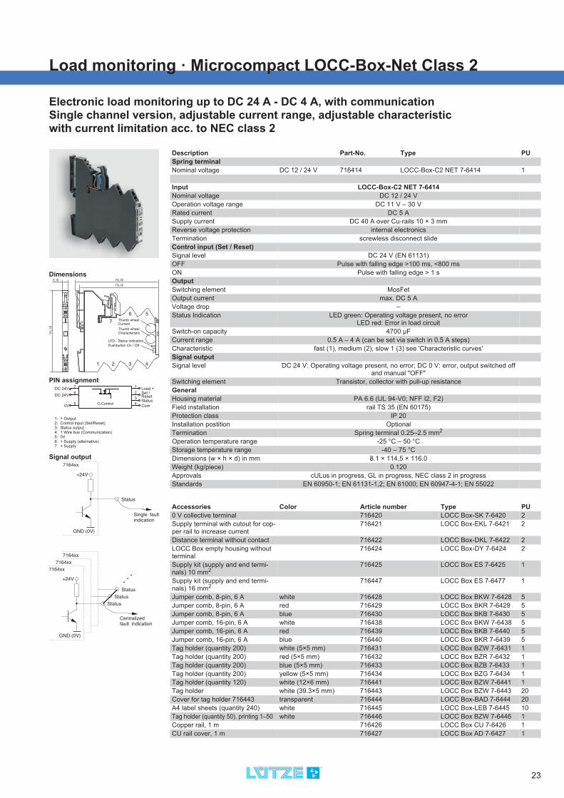
Load monitoring · Microcompact LOCC-Box-Net Class 2
Electronic load monitoring up to DC 24 A - DC 4 A, with communicationSingle channel version, adjustable current range, adjustable characteristicwith current limitation acc. to NEC class 2
Dimensions
PIN assignment
Signal output
7DC 24V
C-Control
6
50V
3
1Load +
Status4
Com
DC 24V2 Set /
Reset
1: + Output2: Control input (Set/Reset)3: Status output4: 1 Wire bus (Communication)5: 0V6: + Supply (alternative)7: + Supply
Description Part-No. Type PUSpring terminalNominal voltage DC 12 / 24 V 716414 LOCC-Box-C2 NET 7-6414 1
Input LOCC-Box-C2 NET 7-6414Nominal voltage DC 12 / 24 VOperation voltage range DC 11 V – 30 VRated current DC 5 ASupply current DC 40 A over Cu-rails 10 × 3 mmReverse voltage protection internal electronicsTermination screwless disconnect slideControl input (Set / Reset)Signal level DC 24 V (EN 61131)OFF Pulse with falling edge >100 ms, <800 msON Pulse with falling edge > 1 sOutputSwitching element MosFetOutput current max. DC 5 AVoltage drop –Status Indication LED green: Operating voltage present, no error
LED red: Error in load circuitSwitch-on capacity 4700 μFCurrent range 0.5 A – 4 A (can be set via switch in 0.5 A steps)Characteristic fast (1), medium (2), slow 1 (3) see 'Characteristic curves'Signal outputSignal level DC 24 V: Operating voltage present, no error; DC 0 V: error, output switched off
and manual "OFF"Switching element Transistor, collector with pull-up resistanceGeneralHousing material PA 6.6 (UL 94-V0; NFF I2, F2)Field installation rail TS 35 (EN 60175)Protection class IP 20Installation postition OptionalTermination Spring terminal 0.25–2.5 mm2
Operation temperature range -25 °C – 50 °CStorage temperature range -40 – 75 °CDimensions (w × h × d) in mm 8.1 × 114.5 × 116.0Weight (kg/piece) 0.120Approvals cULus in progress, GL in progress, NEC class 2 in progressStandards EN 60950-1; EN 61131-1,2; EN 61000; EN 60947-4-1; EN 55022
Accessories Color Article number Type PU0 V collective terminal 716420 LOCC Box-SK 7-6420 2Supply terminal with cutout for cop-per rail to increase current
716421 LOCC Box-EKL 7-6421 2
Distance terminal without contact 716422 LOCC Box-DKL 7-6422 2LOCC Box empty housing without terminal
716424 LOCC Box-DY 7-6424 2
Supply kit (supply and end termi-nals) 10 mm2
716425 LOCC Box ES 7-6425 1
Supply kit (supply and end termi-nals) 16 mm2
716447 LOCC Box ES 7-6477 1
Jumper comb, 8-pin, 6 A white 716428 LOCC Box BKW 7-6428 5Jumper comb, 8-pin, 6 A red 716429 LOCC Box BKR 7-6429 5Jumper comb, 8-pin, 6 A blue 716430 LOCC Box BKB 7-6430 5Jumper comb, 16-pin, 6 A white 716438 LOCC Box BKW 7-6438 5Jumper comb, 16-pin, 6 A red 716439 LOCC Box BKB 7-6440 5Jumper comb, 16-pin, 6 A blue 716440 LOCC Box BKR 7-6439 5Tag holder (quantity 200) white (5×5 mm) 716431 LOCC Box BZW 7-6431 1Tag holder (quantity 200) red (5×5 mm) 716432 LOCC Box BZR 7-6432 1Tag holder (quantity 200) blue (5×5 mm) 716433 LOCC Box BZB 7-6433 1Tag holder (quantity 200) yellow (5×5 mm) 716434 LOCC Box BZG 7-6434 1Tag holder (quantity 120) white (12×6 mm) 716441 LOCC Box BZW 7-6441 1Tag holder white (39.3×5 mm) 716443 LOCC Box BZW 7-6443 20Cover for tag holder 716443 transparent 716444 LOCC Box-BAD 7-6444 20A4 label sheets (quantity 240) white 716445 LOCC Box-LEB 7-6445 10Tag holder (quantity 50), printing 1–50 white 716446 LOCC Box BZW 7-6446 1Copper rail, 1 m 716426 LOCC Box CU 7-6426 1CU rail cover, 1 m 716427 LOCC Box AD 7-6427 1

24
Load monitoring · Microcompact gateway
Gateway for LOCC-Box-Net (716410)Input: LOCCbus (LIN)Output: USB, RS 232, CANopen
Dimensions
PIN assignment
Description Part-No. Type PUSpring terminalNominal voltage DC 12 / 24 V 716459 LOCC-Box-GW 7-6459 1
Input LOCC-Box-GW 7-6459Bus system LOCCbus, basic LINAccess method Single-Master - Multiple SlaveBus technology LinePhysical level 1-wireParticipants 40, max. 254Bus length max. 40 mTransfer rate 9600 BaudData rate 8 Bit + fixed parityTransfer protocol Modified multi-dropOutput USB RS232 CANopenBus system USB 2.0 Full-Speed RS232 CANopenTransfer rate 12 Mbit/s 600 – 11500 bit/s 10 – 1000 kbit/sGeneralNominal voltage DC 12 / 24 VOperation voltage range DC 10 V – 26.4 VRated current max. 50 mAReverse voltage protection YesStatus Indication LED 1 green/red: USB, RS232, Firmware; LED 2 green/red: CANopenInsulation voltage 1.0 kVHousing material PA 6.6 (UL 94-V0; NFF I2, F2)Field installation rail TS 35 (EN 60175)Protection class IP 20Installation postition OptionalTermination Spring terminal : 0.14 - 2.5 mm2 (with AE 1.5 mm2)Operation temperature range -20 °C – 60 °CStorage temperature range -40 – 85 °CDimensions (w × h × d) in mm 6.2 × 90.0 × 115.0Weight (kg/piece) 0.060Approvals CEStandards EN 60950-1, EN 61131-1, -2, EN 60898, EN 60947-4-1, EN 50081Accessories Color Article number Type PUTag holder 4×11 mm white 681313 BZT 0411 100Isolation plate 760809 TP 7-0809 5Labels for laser printer A4 unpun-ched
681031 LEB - A4 1

25
Load monitoring · Gateway
Gateway for LOCC-Box-Net (716410)Input: LOCCbus (LIN)Output: USB, PROFINET-IO
Dimensions
PIN assignment
Description Part-No. Type PUSpring terminalNominal voltage DC 12 / 24 V 716457 LOCC-Box-GWPN 0-6457 1
InputBus system LOCCbus, basic LINAccess method Single-Master - Multiple SlaveBus technology LinePhysical level 1-wireParticipants typ. 40, max. 100Bus length max. 40 mTransfer rate 9600 BaudData rate 8 Bit + fixed parity (Bit 9)Transfer protocol Modified multi-dropOutput USB PROFINET-IOBus system USB 2.0 Full-Speed PROFINET-IOTransfer rate 12 Mbit/s 100 bit/s (IEE 802.3)Interface USB connector, Type B Port_1, Port_2, 2 × RJ-45 female with
galvanic isolation and LEDsGeneralNominal voltage DC 12 / 24 VOperation voltage range 10 – 32 VRated current 120 mA @ 24 VReverse voltage protection YesStatus Indication LED F, yellow - flashing: identification prompt (PROFINET)
LED E, red - flashing: no connection (PROFINET)LED P, green - flashing: operating voltage is connected (POWER)
LED C, green - flashing: data traffic with LOCC Box Net modules (LOCCbus)Link: yellow - 100Base/T-connection
Activity green - valid connection, blanking: data trafficInsulation voltage 1.5 kVHousing material PA (UL94-V0)Field installation rail TS 35 (EN 60175)Protection class IP 20Installation postition OptionalTermination Spring terminal : 0.14 - 2.5 mm2 (with AE 1.5 mm2)Relative humidity max. 90 % non-condensedOperation temperature range -20 °C – 60 °CStorage temperature range -40 – 85 °CDimensions (w × h × d) in mm 22.5 × 99.0 × 114.5Weight (kg/piece) 0.130Approvals CEStandards EN 60950-1, EN 61131-1, -2, EN 60898, EN 60947-4-1, EN 50081CommentsScrew terminal on requestUse

26
Load monitoring · Gateway
Gateway for LOCC-Box-Net (716410)Input: LOCCbus (LIN)Output: USB, PROFIBUS-DP
Dimensions
PIN assignment
Description Part-No. Type PUSpring terminalNominal voltage DC 12 / 24 V 716458 LOCC-Box-GWPB 0-6458 1
InputBus system LOCCbus, basic LINAccess method Single-Master - Multiple SlaveBus technology LinePhysical level 1-wireParticipants typ. 40, max. 84Bus length max. 40 mTransfer rate 9600 BaudData rate 8 Bit + fixed parity (Bit 9)Transfer protocol Modified multi-dropOutput USB PROFIBUS-DPBus system USB 2.0 Full-Speed PROFIBUS-DPTransfer rate 12 Mbit/s max. 12 Mbit/sInterface USB connector, Type B Port_1, SUB-D 9pin with galvanic isola-
tionGeneralNominal voltage DC 12 / 24 VOperation voltage range 10 – 32 VRated current 120 mA @ 24 VReverse voltage protection YesStatus Indication LED D, green - on: data exchange via PROFIBUS-DP
LED E, red - different flash codes for diagnosis of PROFIBUS-DP faults LED P, green - on: operating voltage is supplied (POWER)
LED C, green - flashing: data traffic with LOCC-Box-Net modules (LOCCbus)Insulation voltage 1.5 kVHousing material PA (UL94-V0)Field installation rail TS 35 (EN 60175)Protection class IP 20Installation postition OptionalTermination Spring terminal : 0.14 - 2.5 mm2 (with AE 1.5 mm2)Relative humidity max. 90 % non-condensedOperation temperature range -20 °C – 60 °CStorage temperature range -40 – 85 °CDimensions (w × h × d) in mm 22.5 × 99.0 × 114.5Weight (kg/piece) 0.130Approvals CEStandards EN 60950-1, EN 61131-1, EN 61000, EN 60947-4-1, EN 50016CommentsScrew terminal on requestUse

27
Load monitoring · Gateway
Gateway for LOCC-Box-Net (716410)Input: LOCCbus (LIN)Output: USB, EtherCAT
Dimensions
PIN assignment
Description Part-No. Type PUSpring terminalNominal voltage DC 12 / 24 V 716456 LOCC-Box-GWEC 0-6456 1
InputBus system LOCCbus, basic LINAccess method Single-Master - Multiple SlaveBus technology LinePhysical level 1-wireParticipants typ. 40, max. 64Bus length max. 40 mTransfer rate 9600 BaudData rate 8 Bit + fixed parity (Bit 9)Transfer protocol Modified multi-dropOutput USB EtherCATBus system USB 2.0 Full-Speed EtherCATTransfer rate 12 Mbit/s 100 bit/s (IEE 802.3)Interface USB connector, Type B IN, OUT, 2 × RJ-45 female with galvanic
isolation and LEDsGeneralNominal voltage DC 12 / 24 VOperation voltage range 10 – 32 VRated current 55 mA @ 24 VReverse voltage protection YesStatus Indication LED L, red - flashing: EEPROM error, EEPROM not loaded
LED R, green - lit: ECT RunLED E, green - lit: ECT error
LED C, green - flashing: data traffic with LOCC Box-Net modules (LOCCbus)link/activity: green - 100Base/T-connection, flashes with EtherCAT traffic
Connect: yellow - speed LED,100Base/T-connectionInsulation voltage 1.5 kVHousing material PA (UL94-V0)Field installation rail TS 35 (EN 60175)Protection class IP 20Installation postition OptionalTermination Spring terminal : 0.14 - 2.5 mm2 (with AE 1.5 mm2)Relative humidity max. 90 % non-condensedOperation temperature range -20 °C – 60 °CStorage temperature range -40 – 85 °CDimensions (w × h × d) in mm 22.5 × 99.0 × 114.5Weight (kg/piece) 0.130Approvals CEStandards EN 60950-1, EN 61131-1, -2, EN 60898, EN 60947-4-1, EN 50081CommentsScrew terminal on requestUse

28
Load monitoring · Accessories
LOCC-Box supply setconsisting of supply terminal and end blockmaximum total current 40 A
Dimensions
Description Part-No. Type PU
Nominal voltage DC 12 / 24 V 716425 LOCC-Box-ES 7-6425 1
Input LOCC-Box-ES 7-6425Nominal voltage DC 12 / 24 VRated current max. DC 40 AReverse voltage protection NoTermination Spring terminal : 0.33 – 10 mm2 (AWG 22–8)
conductor connection cross section, single wire (solid): max. 10 mm2
conductor connection cross section, fine wire: max. 6 mm2 conductor connection cross section, fine wire with AEH: max. 6 mm2
Length of stripped insulation 12 mmOutputNominal voltage DC 12 / 24 VOutput current max. DC 40 ATermination screwless disconnect terminalCopper bus bar 3 × 10mmGeneralHousing material PA 6.6 (UL 94-V0; NFF I2, F2)Field installation rail TS 35 (EN 60175)Protection class IP 20Installation postition OptionalOperation temperature range -25 °C – 60 °CStorage temperature range -40 – 85 °CDimensions (w × h × d) in mm 10.0 × 119.4 × 63.7Weight (kg/piece) 0.035Approvals cULusStandards –

29
Load monitoring · Accessories
LOCC-Box supply terminalmaximum total current 40 A
Dimensions
Description Part-No. Type PU
Nominal voltage DC 12 / 24 V 716435 LOCC-Box-EKL 7-6435 2
Input LOCC-Box-EKL 7-6435Nominal voltage DC 12 / 24 VRated current max. DC 40 AReverse voltage protection NoTermination Spring terminal : 0.33 – 10 mm2 (AWG 22–8)
conductor connection cross section, single wire (solid): max. 10 mm2
conductor connection cross section, fine wire: max. 6 mm2 conductor connection cross section, fine wire with AEH: max. 6 mm2
Length of stripped insulation 12 mmOutputNominal voltage DC 12 / 24 VOutput current max. DC 40 ATermination screwless disconnect terminalCopper bus bar 3 × 10mmGeneralHousing material PA 6.6 (UL 94-V0; NFF I2, F2)Field installation rail TS 35 (EN 60175)Protection class IP 20Installation postition OptionalOperation temperature range -25 °C – 60 °CStorage temperature range -40 – 85 °CDimensions (w × h × d) in mm 10.0 × 119.4 × 63.7Weight (kg/piece) 0.035Approvals cULusStandards –

30
Load monitoring · Accessories
LOCC-Box end block
Dimensions
Description Part-No. Type PU
Nominal voltage 716436 LOCC-Box-EB 7-6436 2
GeneralHousing material PA 6.6 (UL 94-V0; NFF I2, F2)Field installation rail TS 35 (EN 60175)Protection class IP 20Installation postition OptionalOperation temperature range -25 °C – 60 °CStorage temperature range -40 – 85 °CDimensions (w × h × d) in mm 10.0 × 119.4 × 62.0Weight (kg/piece) 0.010Approvals cULusStandards –

31
Load monitoring · Accessories
LOCC-Box supply terminalAdditional supply terminal for increased currentmaximum total current 40 A
Dimensions
Use
Description Part-No. Type PU
Nominal voltage DC 12 / 24 V 716421 LOCC-Box-EKL 7-6421 2
Input LOCC-Box-EKL 7-6421Nominal voltage DC 12 / 24 VRated current max. DC 40 AReverse voltage protection NoTermination Spring terminal : 0.33 – 10 mm2 (AWG 22–8)
conductor connection cross section, single wire (solid): max. 10 mm2
conductor connection cross section, fine wire: max. 6 mm2 conductor connection cross section, fine wire with AEH: max. 6 mm2
Length of stripped insulation 12 mmOutputNominal voltage DC 12 / 24 VOutput current max. DC 40 ATermination screwless disconnect terminalCopper bus bar 3 × 10mmGeneralHousing material PA 6.6 (UL 94-V0; NFF I2, F2)Field installation rail TS 35 (EN 60175)Protection class IP 20Installation postition OptionalOperation temperature range -25 °C – 60 °CStorage temperature range -40 – 85 °CDimensions (w × h × d) in mm 10.0 × 119.4 × 63.7Weight (kg/piece) 0.035Approvals cULusStandards –

32
Load monitoring · Accessories
LOCC-Box supply setconsisting of supply terminal and end blockmaximum total current 40 A
Dimensions
Description Part-No. Type PU
Nominal voltage DC 12 / 24 V 716447 LOCC-Box-ES 7-6447 1
Input LOCC-Box-ES 7-6447Nominal voltage DC 12 / 24 VRated current max. DC 40 AReverse voltage protection NoTermination Spring terminal : 0.33 – 16 mm2 (AWG 22–6)
conductor connection cross section, single wire (solid): max. 16 mm2
conductor connection cross section, fine wire: max. 10 mm2 conductor connection cross section, fine wire with AEH: max. 10 mm2
Length of stripped insulation 12 mmOutputNominal voltage DC 12 / 24 VOutput current max. DC 40 ATermination screwless disconnect terminalCopper bus bar 3 × 10mmGeneralHousing material PA 6.6 (UL 94-V0; NFF I2, F2)Field installation rail TS 35 (EN 60175)Protection class IP 20Installation postition OptionalOperation temperature range -25 °C – 60 °CStorage temperature range -40 – 85 °CDimensions (w × h × d) in mm 10.0 × 119.4 × 63.7Weight (kg/piece) –Approvals cULusStandards –

33
Load monitoring · Accessories
LOCC-Box 0V Collective TerminalSingle-channel designmaximum total current 40 A
Dimensions
PIN assignment
Description Part-No. Type PU
Nominal voltage DC 12 / 24 V 716420 LOCC-Box-SK 7-6420 2
Input LOCC-Box-SK 7-6420Nominal voltage DC 12 / 24 VRated current 6× max. DC 10 AReverse voltage protection NoTermination Spring terminal: 0.25–2.5 mm2
Connection 1 – 6OutputOutput current max. DC 40 AVoltage drop –Termination screwless disconnect terminalConnection 7GeneralHousing material PA 6.6 (UL 94-V0; NFF I2, F2)Field installation rail TS 35 (EN 60175)Protection class IP 20Installation postition OptionalOperation temperature range -25 °C – 60 °CStorage temperature range -40 – 85 °CDimensions (w × h × d) in mm 8.1 × 114.5 × 116.0Weight (kg/piece) 0.700Approvals –Standards –

34
Load monitoring · Accessories
LOCC-Box supply terminalLOCC-Box supply terminal for power distributionmaximum total current 40 A
Dimensions
Description Part-No. Type PU
Nominal voltage DC 12 / 24 V 716437 LOCC-Box-ES 7-6437 1
Input LOCC-Box-ES 7-6437Nominal voltage DC 12 / 24 VRated current max. DC 40 AReverse voltage protection NoTermination Spring terminal : 0.33 – 10 mm2 (AWG 22–8)
conductor connection cross section, single wire (solid): max. 10 mm2
conductor connection cross section, fine wire: max. 6 mm2 conductor connection cross section, fine wire with AEH: max. 6 mm2
Length of stripped insulation 12 mmOutputNominal voltage DC 12 / 24 VOutput current max. DC 40 ATermination screwless disconnect terminalCopper bus bar 3 × 10mmGeneralHousing material PA 6.6 (UL 94-V0; NFF I2, F2)Field installation rail TS 35 (EN 60175)Protection class IP 20Installation postition OptionalOperation temperature range -25 °C – 60 °CStorage temperature range -40 – 85 °CDimensions (w × h × d) in mm 10.0 × 119.4 × 63.7Weight (kg/piece) 0.035Approvals cULusStandards –

37
Displays the operating status,current range / characteristic,the load capacity of the cha-racteristic, as well as the up-dated current and voltagevalues.
LOCC-Pads • Monitoring software
LOCC-Pads*Software for the parameterisation of the LOCC-Box-Net, aswell as the analysis and diagnosis of DC 12 / 24 V circuits
Displays theparameters ofthe selectedcharacteristiccurve.
Adjustment parametersfor the parameterisablecharacteristic No. 10
Indicates the cur-rent meter readingsof the selectedmodule
Overview of all connected modules
Recording of all results such as"ON", "OFF" or "SHORT CIRCUIT"with date and time
Plotter function for the selected module – current/voltage progression (analysis)
* in connection with a gateway (CANopen,EtherCAT, Profinet-IO, Profibus-DP)
Menu "Extra"
Overall view

Flammability class UL 94-V0
Bus coupler for allconventional systems
Adjustable characteristics
Adjustable rated current
Manual On /Off
2-channel design
2-pole disconnection
"Power ON" effect
Saving of the last status
Temperature-independentresponse time
Supply - also withgalvanic insulation
Clear labelling
Intelligent current monitoring amanagement system: LCOS-CC
Control Solutions
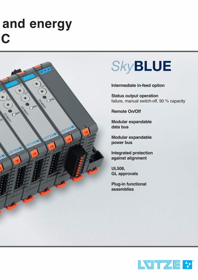
and energy CC
Intermediate in-feed option
Status output operationfailure, manual switch-off, 90 % capacity
Remote On/Off
Modular expandabledata bus
Modular expandablepower bus
Integrated protectionagainst alignment
UL508,GL approvals
Plug-in functionalassemblies

38
Load monitoring · LCOS-CC
Electronic load monitoring up to DC 10 A2-channel version, single pole switching, DC 1 A – DC 10 A, characteristic can be setCollective fault message: single/collective/90% message, Remote Control input
Dimensions
PIN assignmentX1 X2 11
1098
6,754
1,2
3,4
5,6
7,8
12
C-Control
321
R/S- CH1/CH2
Status C 1HStatus C 2HGNDStatus CH1 90%Status CH2 90%Status Out24 VGNDR/S+ C 1HR/S+ C 2H
Load+ C 2H
Load- C 2H
Load+ C 1H
Load- C 1H
Description Part-No. Type PUScrew terminalNominal voltage DC 24 V 779000.2111 LCOS-CC-2K-1P DC 24V 1Push-InNominal voltage DC 24 V 779100.2111 LCOS-CC-2K-1P DC 24V 1
NoteIncluded in the delivery Plug-in terminals : RM5.08 and RM 3.50Not included in the delivery Function carrier and other accessories, see „accessories“InputNominal voltage DC 24 VOperation voltage range DC 20.4 V – 28.8 VRated current DC 10 ASupply current DC 32 A via LCOS power busReverse voltage protection internal electronicsControl input (Set / Reset)Signal level DC 24 V (EN 61131)OFF Pulse with falling edge >100 ms, <800 msON Pulse with falling edge > 1 sGalvanic insulation I/O 2.5 kV, 50 Hz, 1 min.OutputSwitching element MosFetOutput current max. DC 10 AVoltage drop <170 mV (10 A)Status Indication LED green: operating voltage ON, no fault, green flashing: 90 % IB
red flashing: triggered, red: OFFSwitch-on capacity >10000 μFCurrent range 1 A – 10 A (adjustable via switch in 1 A steps)Characteristic fast (1), medium (2), slow 1 (3), slow 2 (4), slow 3 (5), adjustable via switch, see
'characteristic curves'Signal outputSwitching element Transistor in open collector version with Pull Up resistanceSingle channel message (Status CH1, CH2) Acc. to IEC 61131-2: High level, no errors, low level, there are
errors90 % of the rated current IB (Status 90 % CH1, CH2) Acc. to IEC 61131-2: High level <90 %, low level >90 %Insulation voltage –centralised fault signalling (Status Out) Single channel message 1+2, decoupled via diodesGeneralHousing material PA 6.6 (UL 94-V0; NFF I2, F2)Field installation can be connected to LCOS function carrier 22.5 mm (accessories), DIN Rail moun-
ting EN 60715Protection class IP 20Installation postition OptionalVibration resistance Vibration: EN 60068-2-6 Fc, Shock: EN 60068-2-27 EaClimatic conditions Acc. to EN 60721 Stationary use at weather protected locationsTermination X1: Load side: 8-pole measuring strip, CS 5,08
X2: Control side: 12-pole measuring strip, CS 3,5Operation temperature range 0 °C – 55 °CStorage temperature range -40 – 70 °CDimensions (w × h × d) 22.5 × 110.0 × 102.0 mm (including function carrier, without plug-in terminals on
the side)Weight (kg/piece) 0.200Approvals CE, UL601010UL2367Standards EN 61131-2, EN 55016-1-2, EN 60529, EN 61000-6-2, EN 61000-6-4

39
Load monitoring · LCOS-CC
Electronic load monitoring up to DC 10 A1-channel version, two-pole switching, DC 1 A – DC 10 A can be set, characteristic can be setCollective fault message: single/collective/90% message, Remote Control input per channel
Dimensions
PIN assignment
11109
876
4,5
1,23,45,67,8
12
3
1,2
X1 X2
C-ControlStatus+
Status-
Status+ 90%Status- 90%NC24 V
GNDR/S+NC
R/S-
Load+Load-Load+Load-
Description Part-No. Type PUScrew terminalNominal voltage DC 24 V 779000.1211 LCOS-CC-1K-2P DC 24V 1Push-InNominal voltage DC 24 V 779100.1211 LCOS-CC-1K-2P DC 24V 1
NoteIncluded in the delivery Plug-in terminals : RM5.08 and RM 3.50Not included in the delivery Function carrier and other accessories, see „accessories“InputNominal voltage DC 24 VOperation voltage range DC 20.4 – 28.8 VRated current DC 10 ASupply current DC 32 A via LCOS power busReverse voltage protection internal electronicsControl input (Set / Reset)Signal level DC 24 V (EN 61131)OFF Pulse with falling edge >100 ms, <800 msON Pulse with falling edge > 1 sGalvanic insulation I/O 2.5 kV, 50 Hz, 1 min.OutputSwitching element MosFet and relay (galvanic separation both poles: 500 V)Output current max. DC 10 AVoltage drop <170 mV (10 A)Status Indication LED green: operating voltage ON, no fault, green flashing: 90 % IB
red flashing: triggered, red: OFFSwitch-on capacity >10000 μFCurrent range 1 A – 10 A (adjustable via switch in 1 A steps)Characteristic fast (1), medium (2), slow 1 (3), slow 2 (4), slow 3 (5), adjustable via switch, see
'characteristic curves'Signal outputSwitching element One relay with 1 S per signal typeSingle channel message (Status CH1, CH2) 1 N/O contact, AC/DC 250 V, 1 A
Relay closed: errorRelay open: no error
90 % of the rated current IB (Status 90 % CH1, CH2) 1 N/O contact, AC/DC 250 V, 1 ARelay closed: >90 %, Relay open: <90 %
Insulation voltage 2.5 kV, 50 Hz, 1 min.centralised fault signalling –GeneralHousing material PA 6.6 (UL 94-V0; NFF I2, F2)Field installation can be connected to LCOS function carrier 22.5 mm (accessories), DIN Rail moun-
ting EN 60715Protection class IP 20Installation postition OptionalVibration resistance Vibration: EN 60068-2-6 Fc, Shock: EN 60068-2-27 EaClimatic conditions Acc. to EN 60721 Stationary use at weather protected locationsTermination X1: Load side: 8-pole measuring strip, CS 5,08
X2: Control side: 12-pole measuring strip, CS 3,5Operation temperature range 0 °C – 55 °CStorage temperature range -40 – 70 °CDimensions (w × h × d) 22.5 × 110.0 × 102.0 mm (including function carrier, without plug-in terminals on
the side)Weight (kg/piece) 0.200Approvals CE, UL601010UL2367Standards EN 61131-2, EN 55016-1-2, EN 60529, EN 61000-6-2, EN 61000-6-4

40
Modular housing system · LCOS Accessories
Carrier base: 22,5 mmData bus 12-pole power bus AC/DC 500 V, 4×16 AIntegrated PE contact
Description Part-No. Type PU
DescriptionFunction housing 22.5 mm, with cooling slits, closed front plate, no connection opening top/bottom
780100.225.1 LCOS-FGO-225-00/00/00-1 1
Function housing 22.5 mm, with cooling slits, closed front plate, no connection opening top/bottom
780100.225.2 LCOS-FGO-225-00/00/00-1 10
Function housing 22.5 mm, with cooling slits, closed front plate, connection opening top/bottom
780103.225.1 LCOS-FGO-225-01/00/01-1 1
Function housing 22.5 mm, with cooling slits, closed front plate, connection opening top/bottom
780103.225.2 LCOS-FGO-225-01/00/01-1 10
Function carrier 22.5 mm, cannot be expanded with mo-dules, no PE direct contact
780200.225.1 LCOS-FT-NC-225-00-00-1 1
Function carrier 22.5 mm, cannot be expanded with modules, no PE direct contact
780200.225.2 LCOS-FT-NC-225-00-00-1 10
Function carrier 22.5 mm, cannot be expanded with modules, with PE direct contact
780201.225.1 LCOS-FT-PE-225-00-00-1 1
Function carrier 22.5 mm, cannot be expanded with modules, with PE direct contact
780201.225.2 LCOS-FT-PE-225-00-00-1 10
Function carrier 22.5 mm, can be expanded with modules, with PE direct contact
780331.225.1 LCOS-FT-PE-225-00-03-1 1
Function carrier 22.5 mm, can be expanded with modules, with PE direct contact
780331.225.2 LCOS-FT-PE-225-00-03-1 10
Function carrier 22.5 mm, can be expanded with modules, with PE direct contact, power module
780402.225.1 LCOS-FT-PE-225-0P-02-1 1
Function carrier 22.5 mm, can be expanded with modules, with PE direct contact, power module
780402.225.2 LCOS-FT-PE-225-0P-02-1 10
Function carrier 22.5 mm, can be expanded with modules, with PE direct contact, data and power module
780403.225.1 LCOS-FT-PE-225-DP-03-1 1
Function carrier 22.5 mm, can be expanded with modules, with PE direct contact, data and power module
780403.225.2 LCOS-FT-PE-225-DP-03-1 10

41
Modular housing system · LCOS Accessories
Carrier base: 35 mm Data bus 12-pole power bus AC/DC 500 V, 4×16 AIntegrated PE contact
Description Part-No. Type PU
Function housing 35 mm, with cooling slits, closed front plate, no connection opening top/bottom
780100.350.1 LCOS-FGO-350-00/00/00-1 1
Function housing 35 mm, with cooling slits, closed front plate, no connection opening top/bottom
780100.350.2 LCOS-FGO-350-00/00/00-1 10
Function housing 35 mm, with cooling slits, closed front plate, connection opening top/bottom
780103.350.1 LCOS-FGO-350-01/00/01-1 1
Function housing 35 mm, with cooling slits, closed front plate, connection opening top/bottom
780103.350.2 LCOS-FGO-350-01/00/01-1 10
Function carrier 35 mm, cannot be expanded with modules, no PE direct contact
780200.350.1 LCOS-FT-NC-350-00-00-1 1
Function carrier 35 mm, cannot be expanded with modules, no PE direct contact
780200.350.2 LCOS-FT-NC-350-00-00-1 10
Function carrier 35 mm, cannot be expanded with modules, no PE direct contact
780201.350.1 LCOS-FT-PE-350-00-00-1 1
Function carrier 35 mm, cannot be expanded with modules, no PE direct contact
780201.350.2 LCOS-FT-PE-350-00-00-1 10
Function carrier 35 mm, can be expanded withn modules, with PE direct contact
780331.350.1 LCOS-FT-PE-350-00-03-1 1
Function carrier 35 mm, can be expanded withn modules, with PE direct contact
780331.350.2 LCOS-FT-PE-350-00-03-1 10
Function carrier 35 mm, can be expanded with modules, with PE direct contact, power module
780402.350.1 LCOS-FT-PE-350-0P-02-1 1
Function carrier 35 mm, can be expanded with modules, with PE direct contact, power module
780402.350.2 LCOS-FT-PE-350-0P-02-1 10
Function carrier 35 mm, can be expanded with modules, with PE direct contact, data and power module
780403.350.1 LCOS-FT-PE-350-DP-03-1 1
Function carrier 35 mm, can be expanded with modules, with PE direct contact, data and power module
780403.350.2 LCOS-FT-PE-350-DP-03-1 10

42
Modular housing system · LCOS Accessories
Supply Carrier base: 57,5 mm, 70 mmData bus 12-pole power bus AC/DC 500 V, 4×16 AIntegrated PE contact
Description Part-No. Type PU
Function carrier 57.5 mm, with supply DC 24 V, no FBS, with PE direct contact, ready for connection
780700.575.1 LCOS-FTE-PE-575-NC-00-1 1
Function carrier 70 mm, with supply DC 24 V, no FBS, with PE direct contact, ready for connection
780700.700.1 LCOS-FTE-PE-700-NC-00-1 1
Function carrier 57.5 mm, with supply AC 240 V, no FBS, with PE direct contact, ready for connection
780701.575.1 LCOS-FTE-PE-575-NC-01-1 1
Function carrier 70 mm, with supply AC 240 V, no FBS, with PE direct contact, ready for connection
780701.700.1 LCOS-FTE-PE-700-NC-01-1 1
Function carrier 57.5 mm, with supply 3-phase AC 500 V, no FBS, with PE direct contact, ready for connection
780702.575.1 LCOS-FTE-PE-575-NC-02-1 1
Function carrier 70 mm, with supply 3-phase AC 500 V, no FBS, with PE direct contact, ready for connection
780702.700.1 LCOS-FTE-PE-700-NC-02-1 1

43
Modular housing system · LCOS Accessories
Accessories
Description Part-No. Type PU
Replace front plate, closed, function housing 22.5 mm 780600.225.3 LCOS-ZB-FPL-225-00-1 50Replace front plate, closed, function housing 22.5 mm 780600.225.4 LCOS-ZB-FPL-225-00-1 100Replace front plate, closed, function housing 35 mm 780600.350.3 LCOS-ZB-FPL-350-00-1 50Replace front plate, closed, function housing 35 mm 780600.350.4 LCOS-ZB-FPL-350-00-1 100
Data module 22.5 mm 780900.225.2 LCOS-ZB-DM-225-12-00-1 10Data module 22.5 mm 780900.225.3 LCOS-ZB-DM-225-12-00-1 50Data module 35 mm 780900.350.2 LCOS-ZB-DM-350-12-00-1 10Data module 35 mm 780900.350.3 LCOS-ZB-DM-350-12-00-1 50Power module 22.5 mm 780910.225.2 LCOS-ZB-PM-225-00-1 10Power module 22.5 mm 780910.225.3 LCOS-ZB-PM-225-00-1 50Power module 35 mm 780910.350.2 LCOS-ZB-PM-350-00-1 10Power module 35 mm 780910.350.3 LCOS-ZB-PM-350-00-1 50Attachment screws data/power module 780991.000.4 LCOS-ZB-Schraube-00 100Coding pins 780990.000.3 LCOS-ZB-Codier 50Data bridge 12-pole, insulated 780960.012.2 LCOS-ZB-DB-12-00 10Data bridge 12-pole, insulated 780960.012.3 LCOS-ZB-DB-12-00 50Power bridge 1-pole, insulated 780961.001.2 LCOS-ZB-PB 10Power bridge 1-pole, insulated 780961.001.3 LCOS-ZB-PB 50PCB contact Power and PE, 10 A, 1-pole 780962.000.4 LCOS-ZB-LPK-00 100PCB contact Power and PE, 10 A, 1-pole 780962.000.5 LCOS-ZB-LPK-00 500PCB contact Power and PE, 10 A, 1-pole 780962.000.6 LCOS-ZB-LPK-00 1000Labelling plates 5×5 mm, white, frame with 200 plates 780981.000.2 LCOS-ZB-BZS-white-00 10Labelling plates 5×5 mm, red, frame with 200 plates 780982.000.2 LCOS-ZB-BZS-red-00 10Labelling plates 5×5 mm, blue, frame with 200 plates 780983.000.2 LCOS-ZB-BZS-blue-00 10Terminal black, CS 5.08, 8-pole, 2.5 mm2 Push-in, 1-8 printed
780922.000.2 LCOS-ZB_KL_FS-508-25-8-black 10
Terminal black, CS 3.50, 12-pole, 1.5 mm2 Push-in, 1-12 printed
780921.000.2 LCOS-ZB-KL-FS-350-15-12-black 10
Laboratory printed circuit board (PCB) FR4, 1.5 mm 780963.000.2 LCOS-ZB-EB-00-L 10

44
LOCC-Box • Characteristic Curves
All LOCC-Box devices have the same characteristic curves
1-10 A (6A)
Current (A)
Tim
e (m
s)
Current (A)
Tim
e (m
s)
Current (A)
Tim
e (m
s)
Current (A)
Tim
e (m
s)
Current (A)
Tim
e (m
s)
Switch position 1: Characteristic fast
Switch position 3: Characteristic slow-1
Switch position 5: Characteristic slow-3
Switch position 2: Characteristic medium
Switch position 4: Characteristic slow-2

45
Characteristic Curves 0-2 A
Characteristic Curves for the NEC Class 2 device
Switch position 1: Characteristic fast Switch position 2: Characteristic medium
Switch position 3: Characteristic slow
Switch position 1: Characteristic fast Switch position 2: Characteristic medium
Switch position 3: Characteristic slow
LOCC-Box • Characteristic Curves

Part number Index
46
Part-No. Page Part-No. Page Part-No. Page Part-No. Page Part-No. Page Part-No. Page
716400 12716401 12716401.0050 12716403 19716404 19716406 14716407.xxxx 15716408 17716409 13716410 20716410.0050 20716411 21716412.xxxx 16716413 18716414 23716418 22716420 33716421 31716425 28716435 29716436 30716437 34716447 32716456 27716457 25716458 26716459 24779000.1211 39779000.2111 38779100.1211 39779100.2111 38780100.225.1 40780100.225.2 40780100.350.1 41780100.350.2 41780103.225.1 40780103.225.2 40780103.350.1 41780103.350.2 41780200.225.1 40780200.225.2 40780200.350.1 41780200.350.2 41780201.225.1 40780201.225.2 40780201.350.1 41780201.350.2 41780331.225.1 40780331.225.2 40780331.350.1 41780331.350.2 41780402.225.1 40780402.225.2 40780402.350.1 41780402.350.2 41780403.225.1 40780403.225.2 40780403.350.1 41780403.350.2 41780600.225.3 43780600.225.4 43780600.350.3 43780600.350.4 43780700.575.1 42780700.700.1 42
780701.575.1 42780701.700.1 42780702.575.1 42780702.700.1 42780900.225.2 43780900.225.3 43780900.350.2 43780900.350.3 43780910.225.2 43780910.225.3 43780910.350.2 43780910.350.3 43780921.000.2 43780922.000.2 43780960.012.2 43780960.012.3 43780961.001.2 43780961.001.3 43780962.000.4 43780962.000.5 43780962.000.6 43780963.000.2 43780981.000.2 43780982.000.2 43780983.000.2 43780990.000.3 43780991.000.4 43

CopyrightProtected trademarks and trade names are not always labelled as such in this publica-tion. This does not mean they are free names as defined in the trademark and brandmark law. Publication does not imply that the descriptions or pictures used are free fromrights of third parties. The information is published without regard to possible patentprotection. Trade names are used without any guarantee that they can be used freely.In putting together text, pictures and data, we proceeded with the greatest care. Despitethis, the possibility of errors cannot be completely excluded. We therefore reject anylegal responsibility or liability. We are, of course, grateful for any recommendations forimprovement or information useful for making corrections or establishing the truth. Butthe author does not assume any responsibility for the content of these documents.

www.lutze.com
07.2
016.
P2U
B04
.11.
US
.300
0.03
.33
• ©
by
Frie
dric
h Lü
tze
Gm
bH,
Wei
nsta
dt,
Deu
tsch
land
• P
rinte
d in
Ger
man
y. S
ubje
ct t
o te
chni
cal m
odifi
catio
n.
GermanyFriedrich Lütze GmbHPostfach 12 24 (PLZ 71366)Bruckwiesenstrasse 17-19D-71384 WeinstadtTel.: +49 7151 6053-0Fax: +49 7151 6053-277(-288)[email protected]
United KingdomLÜTZE Ltd.Unit 3 Sandy Hill ParkSandy Way, AmingtonTamworth, Staffs, B77 4DUTel.: +44 1827 31333-0Fax: +44 1827 [email protected]
AustriaLÜTZE ElektrotechnischeErzeugnisse [email protected]
SwitzerlandLÜTZE [email protected]
FranceLUTZE [email protected]
SpainLUTZE, S.L. [email protected]
ChinaLuetze Trading (Shanghai) [email protected]
USALUTZE INC.13330 South Ridge DriveCharlotte, NC 28273Tel.: +1 704 504-0222Fax: +1 704 [email protected]
Cables
Cable assemblies
Cable fittings
LSC Wiring System
Module and Interface Technology
Ethernet Connectivity
Suppression Technology
Power Supplies
Railway Technology


![Everything You Always Wanted to Know About LOCC (But Were ... · arXiv:1210.4583v2 [quant-ph] 13 May 2014 Everything You Always Wanted to Know About LOCC (But Were Afraid to Ask)](https://img.pdfslide.net/doc/110x75/5f0b6a5e7e708231d4306875/everything-you-always-wanted-to-know-about-locc-but-were-arxiv12104583v2.jpg)