Embed Size (px)
Citation preview
57
Lockin-ESPI interferometric imaging for remote non-destructive testing
H. Gerhard and G. Busse
Institute for Polymer Testing and Polymer Science (IKP) – Department of Non-Destructive Testing, Stuttgart University, Pfaffenwaldring 32, D-70569 Stuttgart, Germany
Abstract Electronic-speckle-pattern-interferometry (ESPI) is a sensitive interferometric imaging technique that responds to changes of surface topography caused e.g. by pressure changes or by thermal expansion. Hidden defects are revealed by the inhomogeneity of such deformation fields. Unfortunately, field distortion may also be caused by e.g. inhomogeneous excitation. Therefore the lockin technique has been transfered to ESPI in order to enhance its sensitivity by this kind of phase-sensitive narrow-band filtering where finally a self-normalised phase-angle image is obtained. Such an image displays features which are usually deeply hidden in noise, as will be shown on various examples.
Key words: Interferometry, ESPI, Non-destructive Testing, NDE, Lockin, deformation modulation
1. Introduction
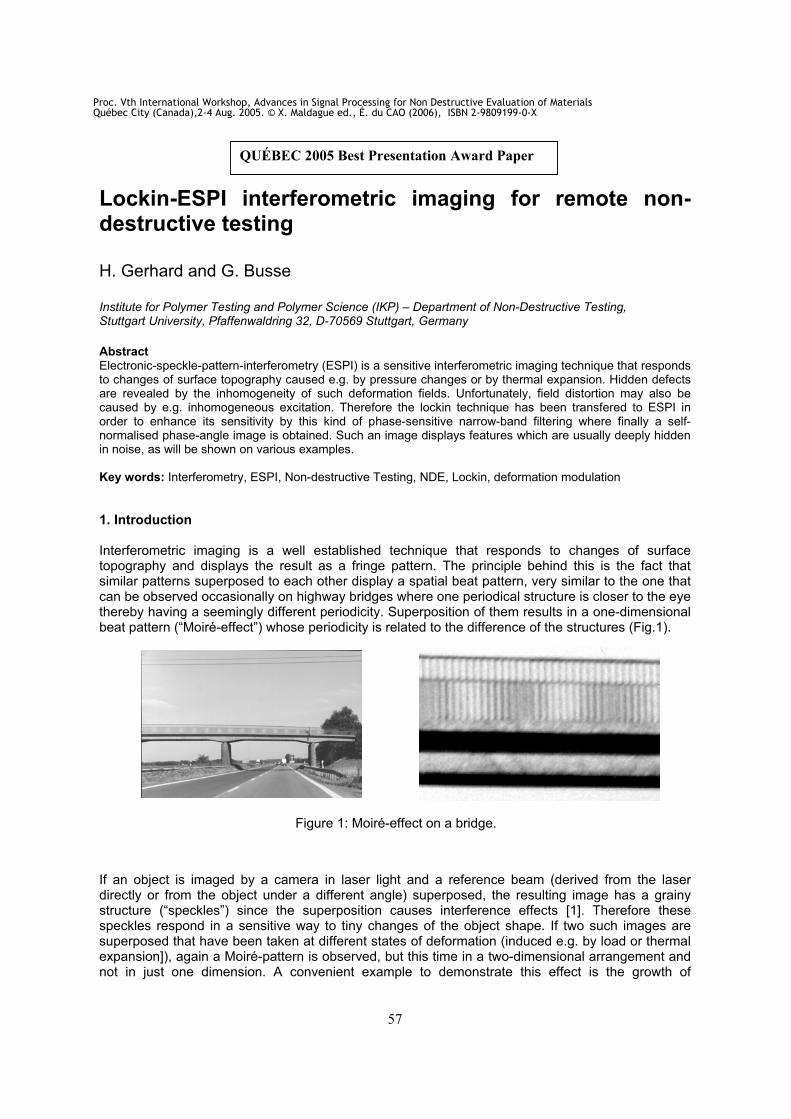
Interferometric imaging is a well established technique that responds to changes of surface topography and displays the result as a fringe pattern. The principle behind this is the fact that similar patterns superposed to each other display a spatial beat pattern, very similar to the one that can be observed occasionally on highway bridges where one periodical structure is closer to the eye thereby having a seemingly different periodicity. Superposition of them results in a one-dimensional beat pattern (“Moiré-effect”) whose periodicity is related to the difference of the structures (Fig.1).
Figure 1: Moiré-effect on a bridge.
If an object is imaged by a camera in laser light and a reference beam (derived from the laser directly or from the object under a different angle) superposed, the resulting image has a grainy structure (“speckles”) since the superposition causes interference effects [1]. Therefore these speckles respond in a sensitive way to tiny changes of the object shape. If two such images are superposed that have been taken at different states of deformation (induced e.g. by load or thermal expansion]), again a Moiré-pattern is observed, but this time in a two-dimensional arrangement and not in just one dimension. A convenient example to demonstrate this effect is the growth of
QUÉBEC 2005 Best Presentation Award Paper
Proc. Vth International Workshop, Advances in Signal Processing for Non Destructive Evaluation of MaterialsQuébec City (Canada),2-4 Aug. 2005. © X. Maldague ed., É. du CAO (2006), ISBN 2-9809199-0-X
58
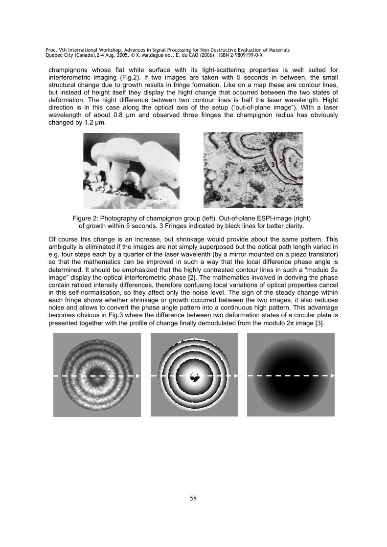
champignons whose flat white surface with its light-scattering properties is well suited for interferometric imaging (Fig.2). If two images are taken with 5 seconds in between, the small structural change due to growth results in fringe formation. Like on a map these are contour lines, but instead of height itself they display the hight change that occurred between the two states of deformation. The hight difference between two contour lines is half the laser wavelength. Hight direction is in this case along the optical axis of the setup (“out-of-plane image”). With a laser wavelength of about 0.8 µm and observed three fringes the champignon radius has obviously changed by 1.2 µm.
Figure 2: Photography of champignon group (left). Out-of-plane ESPI-image (right) of growth within 5 seconds. 3 Fringes indicated by black lines for better clarity.
Of course this change is an increase, but shrinkage would provide about the same pattern. This ambiguity is eliminated if the images are not simply superposed but the optical path length varied in e.g. four steps each by a quarter of the laser wavelenth (by a mirror mounted on a piezo translator) so that the mathematics can be improved in such a way that the local difference phase angle is
determined. It should be emphasized that the highly contrasted contour lines in such a “modulo 2
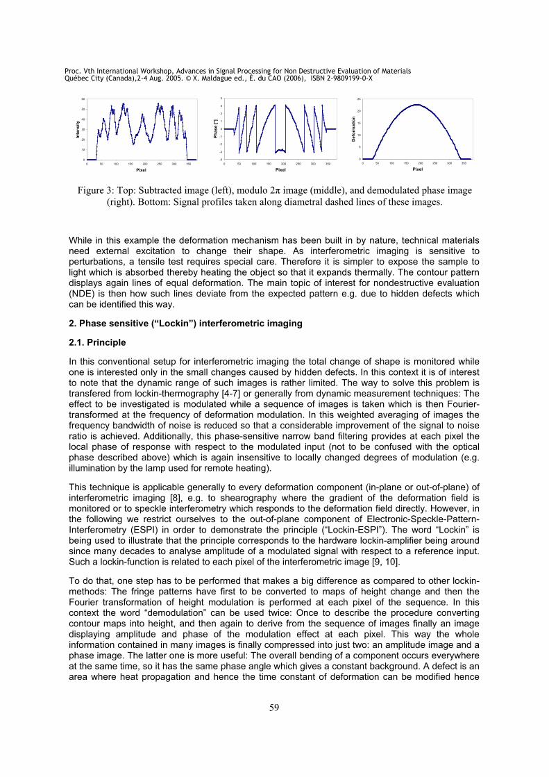
image” display the optical interferometric phase [2]. The mathematics involved in deriving the phase contain ratioed intensity differences, therefore confusing local variations of optical properties cancel in this self-normalisation, so they affect only the noise level. The sign of the steady change within each fringe shows whether shrinkage or growth occurred between the two images, it also reduces noise and allows to convert the phase angle pattern into a continuous high pattern. This advantage becomes obvious in Fig.3 where the difference between two deformation states of a circular plate is
presented together with the profile of change finally demodulated from the modulo 2 image [3].
123
Proc. Vth International Workshop, Advances in Signal Processing for Non Destructive Evaluation of MaterialsQuébec City (Canada),2-4 Aug. 2005. © X. Maldague ed., É. du CAO (2006), ISBN 2-9809199-0-X
59
0
10
20
30
40
50
60
0 50 100 150 200 250 300 350
Pixel
Inte
nsit
y
-4
-3
-2
-1
0
1
2
3
4
0 50 100 150 200 250 300 350
Pixel
Ph
ase [
°]
0
5
10
15
20
25
0 50 100 150 200 250 300 350
Pixel
Defo
rmati
on
Figure 3: Top: Subtracted image (left), modulo 2 image (middle), and demodulated phase image
(right). Bottom: Signal profiles taken along diametral dashed lines of these images.
While in this example the deformation mechanism has been built in by nature, technical materials need external excitation to change their shape. As interferometric imaging is sensitive to perturbations, a tensile test requires special care. Therefore it is simpler to expose the sample to light which is absorbed thereby heating the object so that it expands thermally. The contour pattern displays again lines of equal deformation. The main topic of interest for nondestructive evaluation (NDE) is then how such lines deviate from the expected pattern e.g. due to hidden defects which can be identified this way.
2. Phase sensitive (“Lockin”) interferometric imaging
2.1. Principle
In this conventional setup for interferometric imaging the total change of shape is monitored while one is interested only in the small changes caused by hidden defects. In this context it is of interest to note that the dynamic range of such images is rather limited. The way to solve this problem is transfered from lockin-thermography [4-7] or generally from dynamic measurement techniques: The effect to be investigated is modulated while a sequence of images is taken which is then Fourier-transformed at the frequency of deformation modulation. In this weighted averaging of images the frequency bandwidth of noise is reduced so that a considerable improvement of the signal to noise ratio is achieved. Additionally, this phase-sensitive narrow band filtering provides at each pixel the local phase of response with respect to the modulated input (not to be confused with the optical phase described above) which is again insensitive to locally changed degrees of modulation (e.g. illumination by the lamp used for remote heating).
This technique is applicable generally to every deformation component (in-plane or out-of-plane) of interferometric imaging [8], e.g. to shearography where the gradient of the deformation field is monitored or to speckle interferometry which responds to the deformation field directly. However, in the following we restrict ourselves to the out-of-plane component of Electronic-Speckle-Pattern-Interferometry (ESPI) in order to demonstrate the principle (“Lockin-ESPI”). The word “Lockin” is being used to illustrate that the principle corresponds to the hardware lockin-amplifier being around since many decades to analyse amplitude of a modulated signal with respect to a reference input. Such a lockin-function is related to each pixel of the interferometric image [9, 10].
To do that, one step has to be performed that makes a big difference as compared to other lockin-methods: The fringe patterns have first to be converted to maps of height change and then the Fourier transformation of height modulation is performed at each pixel of the sequence. In this context the word “demodulation” can be used twice: Once to describe the procedure converting contour maps into height, and then again to derive from the sequence of images finally an image displaying amplitude and phase of the modulation effect at each pixel. This way the whole information contained in many images is finally compressed into just two: an amplitude image and a phase image. The latter one is more useful: The overall bending of a component occurs everywhere at the same time, so it has the same phase angle which gives a constant background. A defect is an area where heat propagation and hence the time constant of deformation can be modified hence
Proc. Vth International Workshop, Advances in Signal Processing for Non Destructive Evaluation of MaterialsQuébec City (Canada),2-4 Aug. 2005. © X. Maldague ed., É. du CAO (2006), ISBN 2-9809199-0-X

60
giving a different phase. So the result is that such a defect stands out clearly against an otherwise constant background which is a big advantage as compared to the amplitude image where the tiny additional bump caused by the defect needs to be detected in the presence of the potentially heavily structured background caused by the intact structure. Examples illustrating this important difference will be shown later on.
image sequence
temperature modulation
generated by lamps
deformation modulation
by modulated thermal expansion
tim
e
tim
e
fre
qu
encie
s
FFT
value P(x1, y1) A (x1, y1)
Frames
Pixel P(x1, y1)
image sequence
temperature modulation
generated by lamps
deformation modulation
by modulated thermal expansion
tim
e
tim
e
fre
qu
encie
s
FFT
value P(x1, y1) A (x1, y1)
Frames
Pixel P(x1, y1)
Figure 4: Determination of amplitude image A from the sequence. Phase is determined from the same Fourier transformation.
2.1.Measurement set-up
For the investigations decribed below we used a small home made out-of-plane ESPI set-up where wavelength of the 75mW laser was 532nm.
lens
sample
object beam beam
splitter
laser
computer
reference beam
camera
Sinus modulated lamp
(heat source)
filter
sinus modulated
deformation
A
t
lensdefect
lens
sample
object beam beam
splitter
laser
computer
reference beam
camera
Sinus modulated lamp
(heat source)
filter
sinus modulated
deformation
A
t
lensdefect
Figure 5: Basic setup of Optical Lockin ESPI (OLI) [9].
Proc. Vth International Workshop, Advances in Signal Processing for Non Destructive Evaluation of MaterialsQuébec City (Canada),2-4 Aug. 2005. © X. Maldague ed., É. du CAO (2006), ISBN 2-9809199-0-X
61
For modulated heating we used four 1000W lamps whose power was computer controlled and synchronised to the rate at which the sequence of optical phase images (each resulting from 4 piezo shifted single images) were taken. For clarity it should be mentioned that optical intensity on the sample was less than the one of sunshine in summer. Then all images were unwrapped/demodulated to hight and then Fourier transformed at the modulation frequency which ranged between 0.01Hz and 1Hz. The depth into which the temperature modulation propagates is given by the thermal diffusion length µ with
2
where denotes thermal diffusivity and the angular frequency of lamp modulation [11]. The frequency dependence provides an efficient tool for depth range variation, as is known since some time from thermal wave applications [11-16].
3. Experimental results
3.1. Simulated defects in a PMMA plate
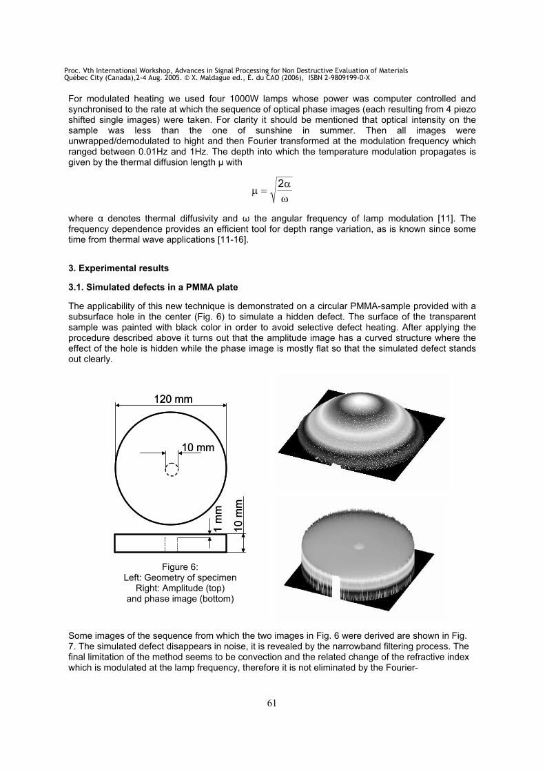
The applicability of this new technique is demonstrated on a circular PMMA-sample provided with a subsurface hole in the center (Fig. 6) to simulate a hidden defect. The surface of the transparent sample was painted with black color in order to avoid selective defect heating. After applying the procedure described above it turns out that the amplitude image has a curved structure where the effect of the hole is hidden while the phase image is mostly flat so that the simulated defect stands out clearly.
120 mm
10 mm
1 m
m
10
mm
120 mm
10 mm
1 m
m
10
mm
Figure 6: Left: Geometry of specimen
Right: Amplitude (top)and phase image (bottom)
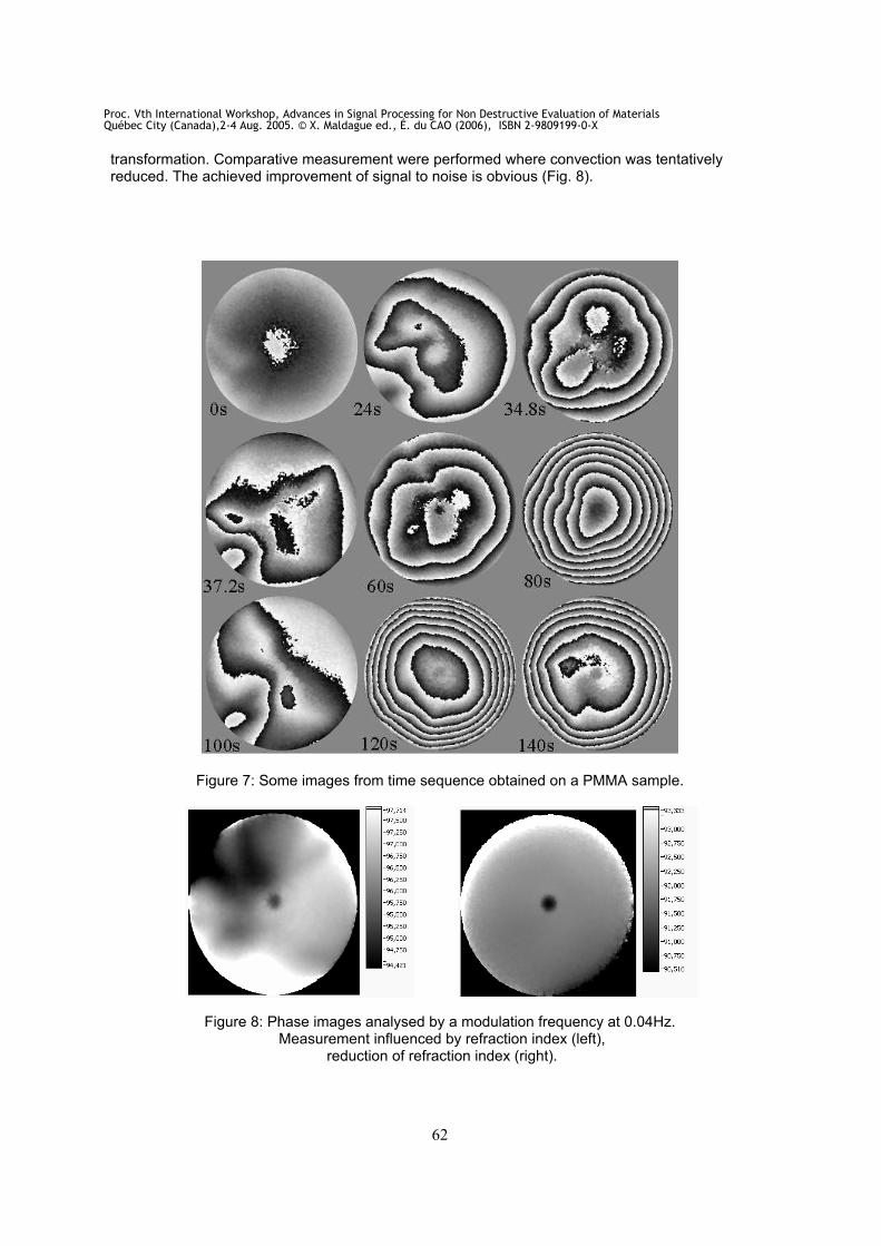
Some images of the sequence from which the two images in Fig. 6 were derived are shown in Fig. 7. The simulated defect disappears in noise, it is revealed by the narrowband filtering process. The final limitation of the method seems to be convection and the related change of the refractive index which is modulated at the lamp frequency, therefore it is not eliminated by the Fourier-
Proc. Vth International Workshop, Advances in Signal Processing for Non Destructive Evaluation of MaterialsQuébec City (Canada),2-4 Aug. 2005. © X. Maldague ed., É. du CAO (2006), ISBN 2-9809199-0-X
62
transformation. Comparative measurement were performed where convection was tentatively reduced. The achieved improvement of signal to noise is obvious (Fig. 8).
Figure 7: Some images from time sequence obtained on a PMMA sample.
Figure 8: Phase images analysed by a modulation frequency at 0.04Hz. Measurement influenced by refraction index (left),
reduction of refraction index (right).
Proc. Vth International Workshop, Advances in Signal Processing for Non Destructive Evaluation of MaterialsQuébec City (Canada),2-4 Aug. 2005. © X. Maldague ed., É. du CAO (2006), ISBN 2-9809199-0-X

63
In another experiment we investigated how defect detectibility depends on modulation frequency. This influence is expected since the depth of modulated heating depends on thermal diffusion length which becomes smaller when the frequency increases [11]. Fig. 9 confirms this relation: The hidden defect is detected only if modulation is 0.15 Hz or lower. Therefore depth profiling is basically possible with Lockin-ESPI.
0.08Hz 0.10Hz 0.12Hz
0.15Hz 0.20Hz 0.25Hz
0.08Hz 0.10Hz 0.12Hz
0.15Hz 0.20Hz 0.25Hz
Figure 9: Phase images obtained with Lockin-ESPI at several frequencies.
3.2 Depth resolved measurements in wood
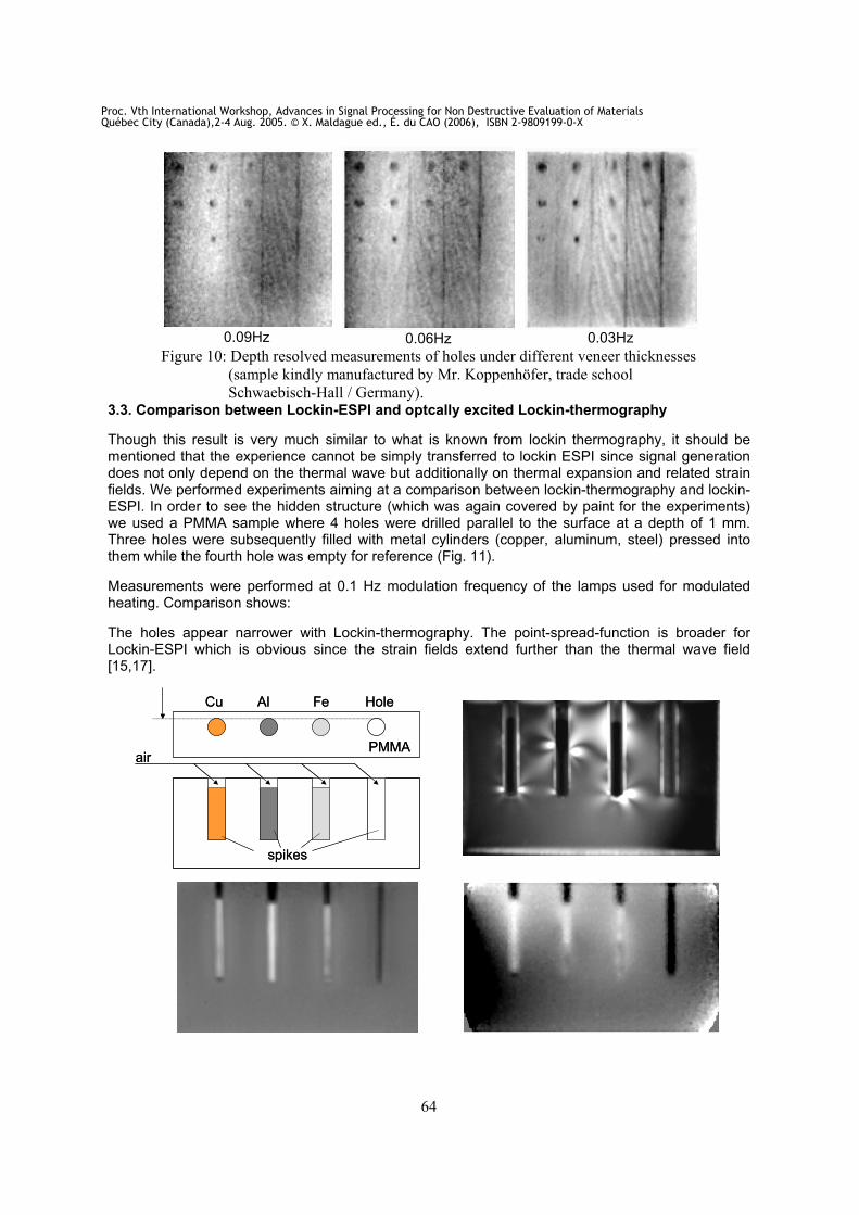
To investigate the influence of modulation frequency on depth range we performed measurements on the wood sample described previously [9] with holes hidden under a layer of veneer (to simulate disbonds) in a matrix arrangement where hole diameter changes along one direction and the thickness of veneer along the other. The reason for this choice of material is that wood is a natural material which is important for furniture where genuine wood is used only for the veneer layer while cheaper material is being used for the core. Disbonds between veneer and substrate can be detected using OLI. In order to investigate this potential we performed measurements between 0.03 and 0.09 Hz. In Fig. 10 the hole diameter decreases from top to bottom while the veneer thickness increases from 0.5mm (left) to 2.5mm (right). At 0.09Hz the holes are detected only if the veneer layer is thinner than 1.5mm. By frequency reduction the penetration depth of the thermal waves increases and allows to detect holes under 2.5mm. This example shows the potential for remote depth profiling of defects.
Proc. Vth International Workshop, Advances in Signal Processing for Non Destructive Evaluation of MaterialsQuébec City (Canada),2-4 Aug. 2005. © X. Maldague ed., É. du CAO (2006), ISBN 2-9809199-0-X
64
0.09Hz 0.06Hz 0.03Hz
Figure 10: Depth resolved measurements of holes under different veneer thicknesses
(sample kindly manufactured by Mr. Koppenhöfer, trade school
Schwaebisch-Hall / Germany). 3.3. Comparison between Lockin-ESPI and optcally excited Lockin-thermography
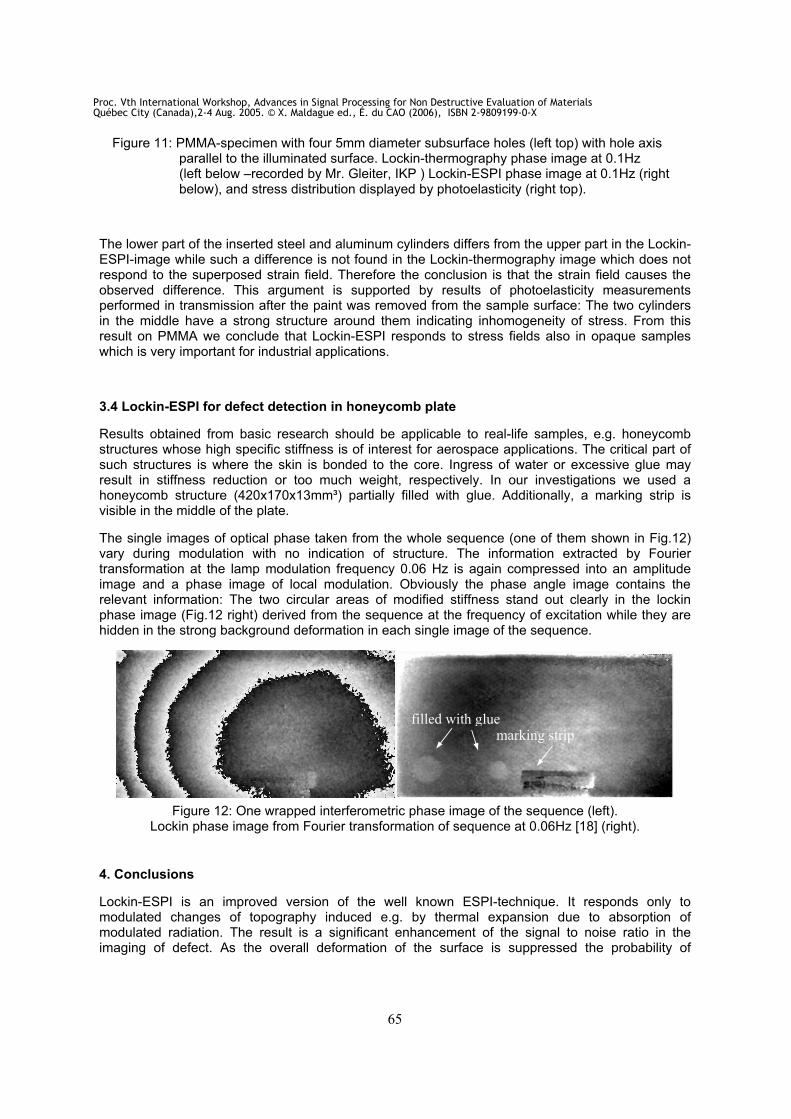
Though this result is very much similar to what is known from lockin thermography, it should be mentioned that the experience cannot be simply transferred to lockin ESPI since signal generation does not only depend on the thermal wave but additionally on thermal expansion and related strain fields. We performed experiments aiming at a comparison between lockin-thermography and lockin-ESPI. In order to see the hidden structure (which was again covered by paint for the experiments) we used a PMMA sample where 4 holes were drilled parallel to the surface at a depth of 1 mm. Three holes were subsequently filled with metal cylinders (copper, aluminum, steel) pressed into them while the fourth hole was empty for reference (Fig. 11).
Measurements were performed at 0.1 Hz modulation frequency of the lamps used for modulated heating. Comparison shows:
The holes appear narrower with Lockin-thermography. The point-spread-function is broader for Lockin-ESPI which is obvious since the strain fields extend further than the thermal wave field [15,17].
Cu Al Fe Hole
PMMAair
spikes
Cu Al Fe Hole
PMMAair
spikes
Proc. Vth International Workshop, Advances in Signal Processing for Non Destructive Evaluation of MaterialsQuébec City (Canada),2-4 Aug. 2005. © X. Maldague ed., É. du CAO (2006), ISBN 2-9809199-0-X
65
Figure 11: PMMA-specimen with four 5mm diameter subsurface holes (left top) with hole axis parallel to the illuminated surface. Lockin-thermography phase image at 0.1Hz (left below –recorded by Mr. Gleiter, IKP ) Lockin-ESPI phase image at 0.1Hz (right below), and stress distribution displayed by photoelasticity (right top).
The lower part of the inserted steel and aluminum cylinders differs from the upper part in the Lockin-ESPI-image while such a difference is not found in the Lockin-thermography image which does not respond to the superposed strain field. Therefore the conclusion is that the strain field causes the observed difference. This argument is supported by results of photoelasticity measurements performed in transmission after the paint was removed from the sample surface: The two cylinders in the middle have a strong structure around them indicating inhomogeneity of stress. From this result on PMMA we conclude that Lockin-ESPI responds to stress fields also in opaque samples which is very important for industrial applications.
3.4 Lockin-ESPI for defect detection in honeycomb plate
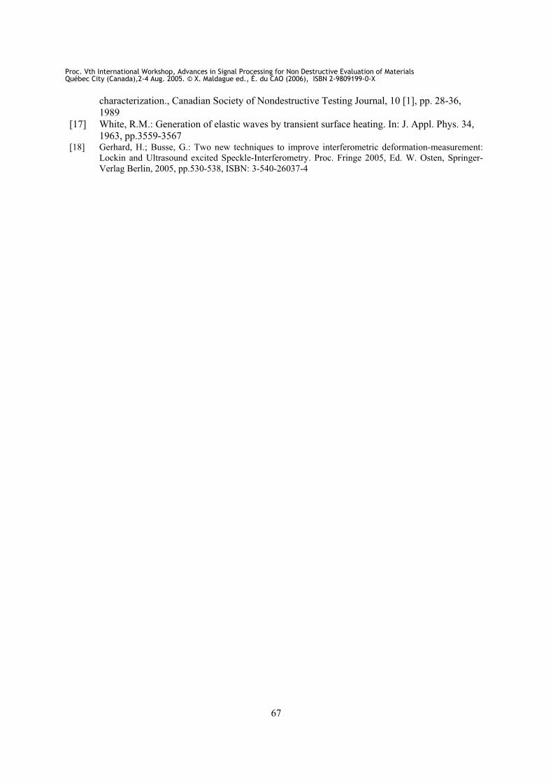
Results obtained from basic research should be applicable to real-life samples, e.g. honeycomb structures whose high specific stiffness is of interest for aerospace applications. The critical part of such structures is where the skin is bonded to the core. Ingress of water or excessive glue may result in stiffness reduction or too much weight, respectively. In our investigations we used a honeycomb structure (420x170x13mm³) partially filled with glue. Additionally, a marking strip is visible in the middle of the plate.
The single images of optical phase taken from the whole sequence (one of them shown in Fig.12) vary during modulation with no indication of structure. The information extracted by Fourier transformation at the lamp modulation frequency 0.06 Hz is again compressed into an amplitude image and a phase image of local modulation. Obviously the phase angle image contains the relevant information: The two circular areas of modified stiffness stand out clearly in the lockin phase image (Fig.12 right) derived from the sequence at the frequency of excitation while they are hidden in the strong background deformation in each single image of the sequence.
Figure 12: One wrapped interferometric phase image of the sequence (left). Lockin phase image from Fourier transformation of sequence at 0.06Hz [18] (right).
4. Conclusions
Lockin-ESPI is an improved version of the well known ESPI-technique. It responds only to modulated changes of topography induced e.g. by thermal expansion due to absorption of modulated radiation. The result is a significant enhancement of the signal to noise ratio in the imaging of defect. As the overall deformation of the surface is suppressed the probability of
filled with gluemarking strip
Proc. Vth International Workshop, Advances in Signal Processing for Non Destructive Evaluation of MaterialsQuébec City (Canada),2-4 Aug. 2005. © X. Maldague ed., É. du CAO (2006), ISBN 2-9809199-0-X
66
detection (POD) is much enhanced. Also depth analysis of the defects is possible by variation of the lockin frequency.
Further developments to be transferred from other techniques are obvious: Instead of performing depth analysis by subsequent measurements at different frequencies one can as well use burst excitation (containing a broad frequency spectrum) and transform just one obtained sequence at various frequencies. Also, nonlinearities can be investigated by analysing the sequence at overtone frequencies as a response to monofrequency sinusoidal input. Such images would display selectively defects (e.g. clapping of disbonds).
In that sense this paper can be considered as a first feasibility investigation that explores the potential of a widely applicable new technique expanding the scope of applications for interferometric imaging in the field of remote NDE.
REFERENCES
[1] Jones, R.; Wykes, C.: Holographic and Speckle Interferometry. A discussion of the theory, practice
and application of the techniques. Cambridge: Cambridge University Press, 1983
[2] Cloud, G.: Optical Methods of Engineering Analysis. Cambridge: University of Cambridge, 1995
[3] Ghiglia, D.; Pritt, M.: Two-Dimensional Phase Unwrapping: Theory, Algorithms, and Software.
Wiley, New York, 1998
[4] Carlomagno, G.; Berardi, P.: Unsteady thermotopography in non-destructive testing. In: Proc. 3nd
Biannual Exchange, St. Louis/USA, 24.-26. August 1976, pp.33-39
[5] Beaudoin, J. L.; Merienne, E.; Danjoux, R.; Egee, M.: Numerical system for infrared scanners and
application to the subsurface control of materials by photothermal radiometry. Infrared Technology
and Applications SPIE Vol.590, 1985, p. 287
[6] Kuo, P. K; Feng, Z. J.; Ahmed,T.; Favro L. D.; Thomas, R. L.; Hartikainen, J.: Parallel thermal wave
imaging using a vector lock-in video technique. In: Photoacoustic and Photothermal Phenomena
(Hrsg. P. Hess and J. Pelzl). Springer-Verlag, Heidelberg 1987, pp. 415-418
[7] Busse, G.: Lockin thermography. Nondestructive Testing Handbook. Vol 3: Infrared and Thermal
Testing (Ed. X. Maldague). American Society for Nondestructive Testing Inc., Columbus,OH, 2001,
pp. 318-327, ISBN 1-57117-044-8
[8] Patent DE 4203272- C2, 1992
[9] Gerhard, H.; Busse, G.: Use of ultrasound excitation and optical-lockin method for speckle
interferometry displacement imaging. In: Green, R.E. Jr.; Djordjevic, B.B.; Hentschel, M.P.
(Eds): Nondestructive Characterisation of Materials XI, Springer-Verlag Berlin, 2003, pp.
525-534, ISBN: 3-540-40154-7
[10] Gerhard, H.; Busse, G.: Zerstörungsfreie Prüfung mit neuen Interferometrie-Verfahren. In:
Materialprüfung, Vol. 45 Nr. 3, 2003, pp. 78-84
[11] Rosencwaig, A.; Gersho, A.: Theory of the photo-acoustic effect with solids. J. Appl. Phys.,
1976, pp. 64-69 [12] Busse, G.: Optoacoustic phase angle measurement for probing a metal. In:Appl. Phys. Lett. Vol. 35,
1979, pp.759-760
[13] Rosencwaig, A.; Busse, G.: High resolution photoacoustic thermal wave microscopy. Appl.
Phys. Lett. 36, 1980, pp. 725-727
[14] Opsal, J.; Rosencwaig, A.: Thermal wave depth profiling: Theory., J. Appl. Phys. 53, 1982,
pp. 4240-4246
[15] Busse, G.; Rosencwaig, A.: Thermal wave piezoelectric and microphone detection for non-
destructive evaluation: a comparison. In: J. Photoacoustics 1, 1983, pp. 365-369
[16] Maldague, X.; Krapez, J.C.; Cielo, P.; Poussart, D.: Inspection of materials and structures by
infrared thermography: signal processing techniques for defect enhancement and
Proc. Vth International Workshop, Advances in Signal Processing for Non Destructive Evaluation of MaterialsQuébec City (Canada),2-4 Aug. 2005. © X. Maldague ed., É. du CAO (2006), ISBN 2-9809199-0-X
67
characterization., Canadian Society of Nondestructive Testing Journal, 10 [1], pp. 28-36,
1989
[17] White, R.M.: Generation of elastic waves by transient surface heating. In: J. Appl. Phys. 34,
1963, pp.3559-3567 [18] Gerhard, H.; Busse, G.: Two new techniques to improve interferometric deformation-measurement:
Lockin and Ultrasound excited Speckle-Interferometry. Proc. Fringe 2005, Ed. W. Osten, Springer-
Verlag Berlin, 2005, pp.530-538, ISBN: 3-540-26037-4
Proc. Vth International Workshop, Advances in Signal Processing for Non Destructive Evaluation of MaterialsQuébec City (Canada),2-4 Aug. 2005. © X. Maldague ed., É. du CAO (2006), ISBN 2-9809199-0-X