Embed Size (px)
Citation preview
LOCKING MECHANISM FOR IXV RE-ENTRY DEMONSTRATOR FLAP CONTROL SYSTEM
Didier Verhoeven, S.A.B.C.A., 1470 chaussée de Haecht, 1130 Brussels, Belgium [email protected]
Didier Renté, T.A.E.M., 5 rue du clos d'en haut, 78702 Conflans-Sainte-Honorine, France,
ABSTRACT
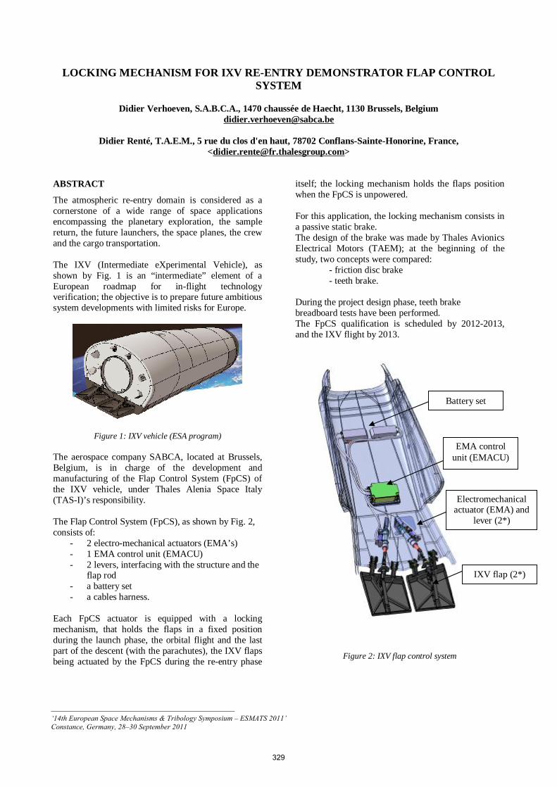
The atmospheric re-entry domain is considered as a cornerstone of a wide range of space applications encompassing the planetary exploration, the sample return, the future launchers, the space planes, the crew and the cargo transportation. The IXV (Intermediate eXperimental Vehicle), as shown by Fig. 1 is an “intermediate” element of a European roadmap for in-flight technology verification; the objective is to prepare future ambitious system developments with limited risks for Europe.
Figure 1: IXV vehicle (ESA program) The aerospace company SABCA, located at Brussels, Belgium, is in charge of the development and manufacturing of the Flap Control System (FpCS) of the IXV vehicle, under Thales Alenia Space Italy (TAS-I)’s responsibility. The Flap Control System (FpCS), as shown by Fig. 2, consists of:
- 2 electro-mechanical actuators (EMA’s) - 1 EMA control unit (EMACU) - 2 levers, interfacing with the structure and the
flap rod - a battery set - a cables harness.
Each FpCS actuator is equipped with a locking mechanism, that holds the flaps in a fixed position during the launch phase, the orbital flight and the last part of the descent (with the parachutes), the IXV flaps being actuated by the FpCS during the re-entry phase
itself; the locking mechanism holds the flaps position when the FpCS is unpowered. For this application, the locking mechanism consists in a passive static brake. The design of the brake was made by Thales Avionics Electrical Motors (TAEM); at the beginning of the study, two concepts were compared:
- friction disc brake - teeth brake.
During the project design phase, teeth brake breadboard tests have been performed. The FpCS qualification is scheduled by 2012-2013, and the IXV flight by 2013.
Figure 2: IXV flap control system
Battery set
EMA control unit (EMACU)
Electromechanical actuator (EMA) and
lever (2*)
IXV flap (2*)
_________________________________________________ ‘14th European Space Mechanisms & Tribology Symposium – ESMATS 2011’ Constance, Germany, 28–30 September 2011
329
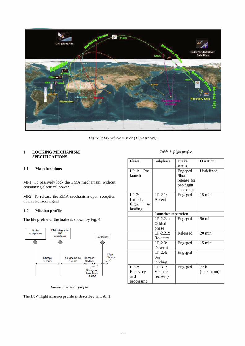
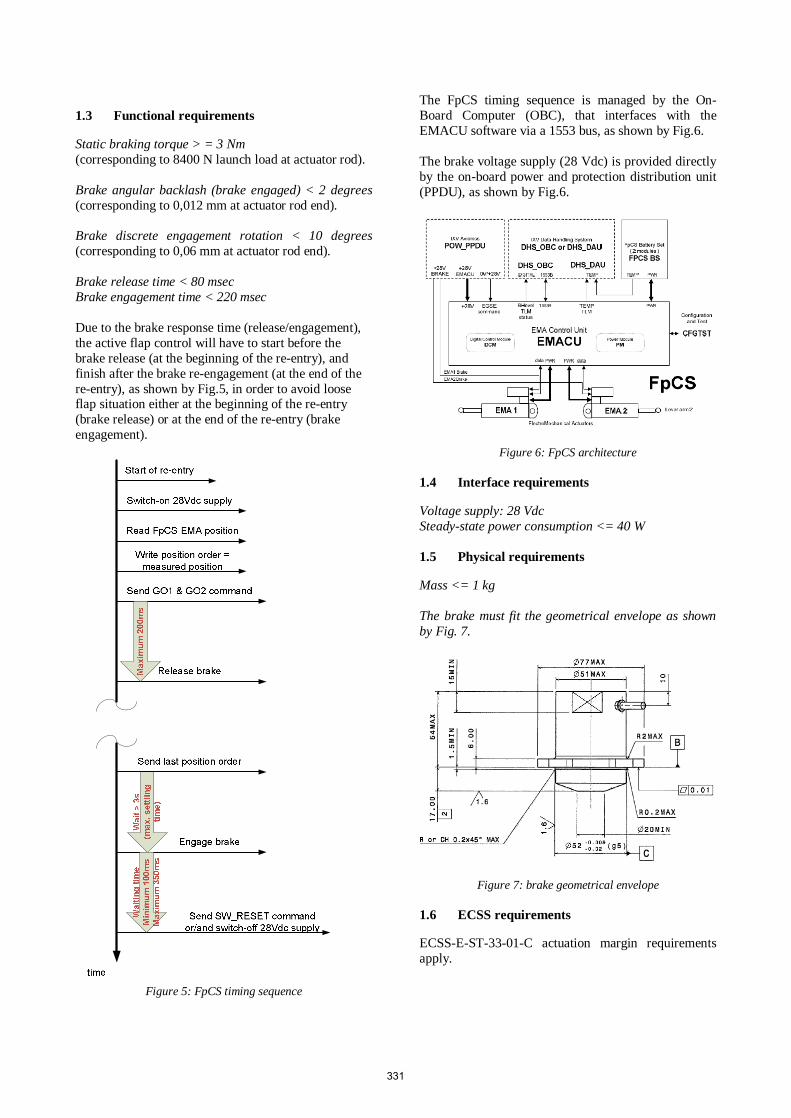
Figure 3: IXV vehicle mission (TAS-I picture) 1 LOCKING MECHANISM
SPECIFICATIONS
1.1 Main functions
MF1: To passively lock the EMA mechanism, without consuming electrical power. MF2: To release the EMA mechanism upon reception of an electrical signal. 1.2 Mission profile
The life profile of the brake is shown by Fig. 4.
Figure 4: mission profile The IXV flight mission profile is described in Tab. 1.
Table 1: flight profile
Phase Subphase Brake
status Duration
LP-1: Pre-launch
Engaged Short release for pre-flight check-out
Undefined
LP-2: Launch, flight & landing
LP-2.1: Ascent
Engaged 15 min
Launcher separation LP-2.2.1:
Orbital phase
Engaged 50 min
LP-2.2.2: Re-entry
Released 20 min
LP-2.3: Descent
Engaged 15 min
LP-2.4: Sea landing
Engaged
LP-3: Recovery and processing
LP-3.1: Vehicle recovery
Engaged 72 h (maximum)
330
1.3 Functional requirements
Static braking torque > = 3 Nm (corresponding to 8400 N launch load at actuator rod). Brake angular backlash (brake engaged) < 2 degrees (corresponding to 0,012 mm at actuator rod end). Brake discrete engagement rotation < 10 degrees (corresponding to 0,06 mm at actuator rod end). Brake release time < 80 msec Brake engagement time < 220 msec Due to the brake response time (release/engagement), the active flap control will have to start before the brake release (at the beginning of the re-entry), and finish after the brake re-engagement (at the end of the re-entry), as shown by Fig.5, in order to avoid loose flap situation either at the beginning of the re-entry (brake release) or at the end of the re-entry (brake engagement).
Figure 5: FpCS timing sequence
The FpCS timing sequence is managed by the On-Board Computer (OBC), that interfaces with the EMACU software via a 1553 bus, as shown by Fig.6. The brake voltage supply (28 Vdc) is provided directly by the on-board power and protection distribution unit (PPDU), as shown by Fig.6.
Figure 6: FpCS architecture 1.4 Interface requirements
Voltage supply: 28 Vdc Steady-state power consumption <= 40 W 1.5 Physical requirements
Mass <= 1 kg The brake must fit the geometrical envelope as shown by Fig. 7.
Figure 7: brake geometrical envelope 1.6 ECSS requirements
ECSS-E-ST-33-01-C actuation margin requirements apply.
331
1.7 Environmental requirements
a) Vacuum environment Pressure < 10-6 mbar (or hPa)
b) Temperature range Brake temperature range: -10 °C; + 120°C. (external – without brake dissipation) The maximum operating temperature is + 65°C for the actuator; however, due to internal dissipation during the re-entry, the temperature at actuator/brake interface could raise to nearly 120°C.
c) Sinus vibrations
AXIAL DIRECTION Design spectrum Qualification spectrum [Hz] [g] [g]
5 2.5 3.0 30 7.5 9.5 60 7.5 à 15.0 9.5 à 19.0 100 15.0 19.0
LATERAL DIRECTION
Qualification spectrum [Hz] [g]
5 5.0 30 27.0 40 27.0 à 70 100 70
d) Quasi-static loads
Load event Longitudinal Load
(X axis) Lateral Load
Ascent +8g / -4.5g +/- 3.5g
e) Acoustic spectrum PSD Flight (OOP) PSD qualification (OOP) Freq (Hz) PSD (g2/Hz) Freq (Hz) PSD (g2/Hz)
20 0.0001 20 0.000414 80 0.01 80 0.0414
600 0.01 600 0.0414 2000 0.001 2000 0.00414
OOP: out of IXV plane direction
f) Shocks Shock response spectrum (SRS): up to 1578 g @ 10000 Hz.
2 BRAKE CONCEPT
2.1 Friction disc concept
A spring friction brake is a device with a disc driven in rotation by a shaft, and locked in rotation by friction on a non-rotating armature pressed by springs, which provide axial load. The static braking torque value is given by:
T = F * µ * r * n
Where : T : torque (N.m) F : axial load provided by the springs force (N) µ : friction coefficient r : mean radius of friction disc (m) n : number of friction faces
The necessary axial force is given by:
n**r µ
Ta
F =
This concept is valid when the friction coefficient range is well-known and stable in all operational and environmental conditions. For the lowest values of the friction coefficient, the necessary force would in theory tend towards an infinite value; in practical, there would be a risk of brake slipping, even for large values of axial spring forces. 2.2 Teeth brake concept
The principle of the teeth brake is the following:
332
When a torque is applied on the disc, the resulting axial
load (a
F ) on the armature is given by:
[ ]ϕϕθ tgtgT
aF −−= )(*
r
Where: T : braking torque (Nm) r : teeth radius (m) θ : half angle of teeth (°)
ϕtg : friction coefficient = µ
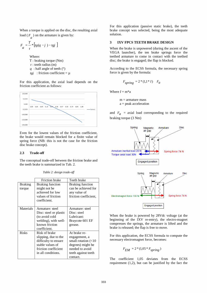
For this application, the axial load depends on the friction coefficient as follows:
Even for the lowest values of the friction coefficient, the brake would remain blocked for a finite value of spring force (NB: this is not the case for the friction disc brake concept). 2.3 Trade-off
The conceptual trade-off between the friction brake and the teeth brake is summarized in Tab. 2.
Table 2: design trade-off
Friction brake Teeth brake Braking torque
Braking function might not be achieved for low values of friction coefficient.
Braking function can be achieved for any value of friction coefficient,
Materials Armature: steel Disc: steel or plastic (to avoid cold welding), with well-known friction coefficient.
Armature: steel Disc: steel Lubricant: Braycote 601 EF grease.
Risks Risk of brake slipping, due to the difficulty to ensure stable values of friction coefficient in all conditions.
At brake re-engagement, a small rotation (<10 degrees) might be needed to avoid teeth against teeth contact.
For this application (passive static brake), the teeth brake concept was selected, being the most adequate solution. 3 IXV FPCS TEETH BRAKE DESIGN
When the brake is unpowered (during the ascent of the VEGA launcher), the ten brake springs force the teethed armature to come in contact with the teethed disc; the brake is engaged; the flap is blocked. According to the ECSS formula, the necessary spring force is given by the formula:
aFIspringF += )*1,1(*2
Where I = m*a m = armature mass a = peak acceleration
and aF = axial load corresponding to the required
braking torque (3 Nm)
When the brake is powered by 28Vdc voltage (at the beginning of the IXV re-entry), the electro-magnet compresses the springs, the armature is lifted and the brake is released; the flap is free to move. For this application, the ECSS formula to compute the necessary electromagnet force, becomes:
)*05,1(*2 springFEMF =
The coefficient 1,05 deviates from the ECSS requirement (1,2), but can be justified by the fact the
333
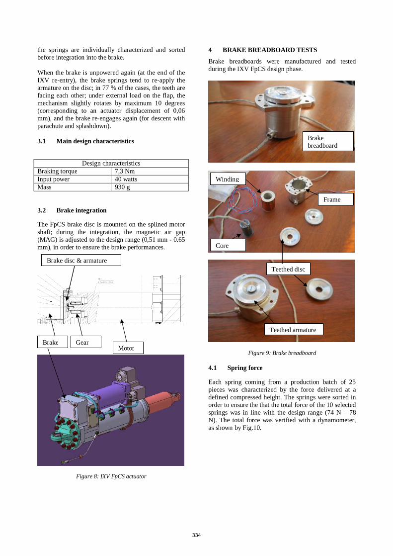
the springs are individually characterized and sorted before integration into the brake. When the brake is unpowered again (at the end of the IXV re-entry), the brake springs tend to re-apply the armature on the disc; in 77 % of the cases, the teeth are facing each other; under external load on the flap, the mechanism slightly rotates by maximum 10 degrees (corresponding to an actuator displacement of 0,06 mm), and the brake re-engages again (for descent with parachute and splashdown). 3.1 Main design characteristics
Design characteristics
Braking torque 7,3 Nm Input power 40 watts Mass 930 g
3.2 Brake integration
The FpCS brake disc is mounted on the splined motor shaft; during the integration, the magnetic air gap (MAG) is adjusted to the design range (0,51 mm - 0.65 mm), in order to ensure the brake performances.
Figure 8: IXV FpCS actuator
4 BRAKE BREADBOARD TESTS
Brake breadboards were manufactured and tested during the IXV FpCS design phase.
Figure 9: Brake breadboard 4.1 Spring force
Each spring coming from a production batch of 25 pieces was characterized by the force delivered at a defined compressed height. The springs were sorted in order to ensure the that the total force of the 10 selected springs was in line with the design range (74 N – 78 N). The total force was verified with a dynamometer, as shown by Fig.10.
Motor Brake Gear
Brake disc & armature
Winding
Core
Teethed armature
Teethed disc
Frame
Brake breadboard
334

Figure 10: Spring force measurement 4.2 Electromagnet force
The electromagnet force was measured with a force tester and a hand lever, as shown by Fig.11.
Figure 11: Electromagnet force measurement 4.3 Response time
The measurement of the response time was based on the principle of armature moving detection. Typical brake release/engagement curves are shown by figures 12 and 13: Brake release:
Figure 12: Brake release time measurement
Brake engagement:
Figure 13: Brake engagement time measurement 4.4 Braking torque
The braking torque was measured with a torquemeter and a lever; by hand, the torque was gradually applied on the tool shaft; the measured braking torque was higher than 8 Nm, providing enough margin with respect to the FpCS need (3 Nm), in accordance with the ECSS standard requirements. 4.5 Random vibrations tests
Random vibrations were applied along the brake longitudinal axis; during the test, the brake was not energized, but was loaded by an external torque.
Figure 14: Vibrations test set-up The force of springs appeared to be sufficient to maintain the brake engaged during the random vibrations. After the vibrations, the brake operated correctly; the brake was correctly released when it was energized. 4.6 Endurance test in vacuum
The endurance and vacuum tests have been performed at SABCA Brussels facilities; during the test, the pressure inside the vacuum chamber was recorded between 10-4 and 10-6 mbar (or 10-6 hPa).
335
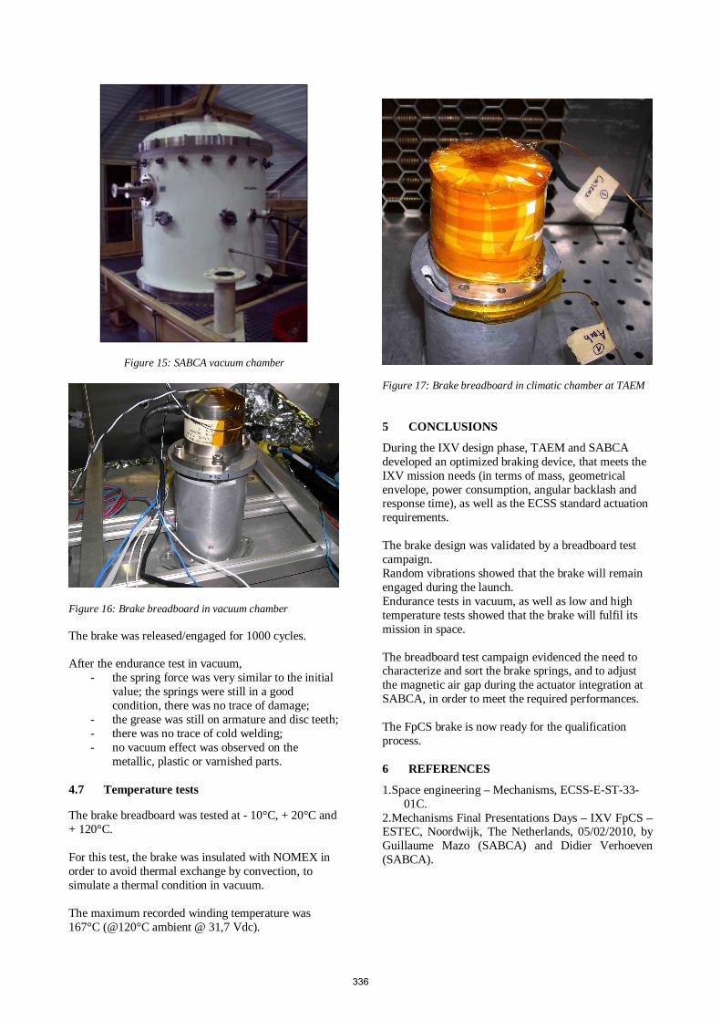
Figure 15: SABCA vacuum chamber
Figure 16: Brake breadboard in vacuum chamber The brake was released/engaged for 1000 cycles. After the endurance test in vacuum,
- the spring force was very similar to the initial value; the springs were still in a good condition, there was no trace of damage;
- the grease was still on armature and disc teeth; - there was no trace of cold welding; - no vacuum effect was observed on the
metallic, plastic or varnished parts. 4.7 Temperature tests
The brake breadboard was tested at - 10°C, + 20°C and + 120°C. For this test, the brake was insulated with NOMEX in order to avoid thermal exchange by convection, to simulate a thermal condition in vacuum. The maximum recorded winding temperature was 167°C (@120°C ambient @ 31,7 Vdc).
Figure 17: Brake breadboard in climatic chamber at TAEM 5 CONCLUSIONS
During the IXV design phase, TAEM and SABCA developed an optimized braking device, that meets the IXV mission needs (in terms of mass, geometrical envelope, power consumption, angular backlash and response time), as well as the ECSS standard actuation requirements. The brake design was validated by a breadboard test campaign. Random vibrations showed that the brake will remain engaged during the launch. Endurance tests in vacuum, as well as low and high temperature tests showed that the brake will fulfil its mission in space. The breadboard test campaign evidenced the need to characterize and sort the brake springs, and to adjust the magnetic air gap during the actuator integration at SABCA, in order to meet the required performances. The FpCS brake is now ready for the qualification process. 6 REFERENCES
1.Space engineering – Mechanisms, ECSS-E-ST-33-01C.
2.Mechanisms Final Presentations Days – IXV FpCS – ESTEC, Noordwijk, The Netherlands, 05/02/2010, by Guillaume Mazo (SABCA) and Didier Verhoeven (SABCA).
336

![%UDG 6WROW]IXV · %UDG 6WROW]IXV. rd-in-IAB Bird-in-Hand Family Re staurant Dear Guest: Thank you for stopping by the Bird in Hand Family Restaurant & Smorgasbord. From the moment](https://img.pdfslide.net/doc/110x75/5ecef850a9fb887b3012cfa3/udg-6wrowixv-udg-6wrowixv-rd-in-iab-bird-in-hand-family-re-staurant-dear-guest.jpg)