Embed Size (px)
Citation preview

Michael R. Lockwood Construction Management National Museum of the Marine Corps – Quantico, VA
- Page 95 -
4-Dimensional Virtual Simulation Modeling for Structural Steel Erection Planning
Executive Summary
The National Museum of the Marine Corps has a monumental skylight system
composed of a structural steel truss mast, structural steel framing, glazing, and metal
cladding. As a result, the erection of the structural steel was carefully developed to
determine the most efficient and safest erection sequence possible.
The structural steel erection contractor developed a 120-page document
containing detailed information of the structural steel erection sequence, detailed sketches
of the erection phases and information regarding the temporary falsework and lifting lugs
on the structural members. The document is very complex and thorough and provides all
the necessary information for the on-site erection crew to successfully erect the steel
members. However, this document can be hard for an outsider to comprehend and can be
difficult to communicate to other individuals not directly associated with the structural
steel erection.
Therefore, the use of 4-dimensional virtual simulation modeling for structural
steel erection planning has been proposed. The use of 4-dimensional modeling can assist
the steel erector in the development of the structural erection plan and the erection
document can also be developed based on this model. This model can be used to
communicate and coordinate the structural erection phase of the project to other
contractors on site (at that stage of construction). The 4-dimensional model can also be
used to inform the owner (and other individuals) of the intentions of the steel erection and
can allow the steel contractor to address any questions and concerns of the owner prior to
commencing the steel erection on the project.
The implementation of 4-dimensional virtual modeling can be a vital tool in the
development of a structural erection plan and can be used to further communicate this
plan to the many individuals associated with the construction of a project.
Michael R. Lockwood Construction Management National Museum of the Marine Corps – Quantico, VA
- Page 96 -
Overview
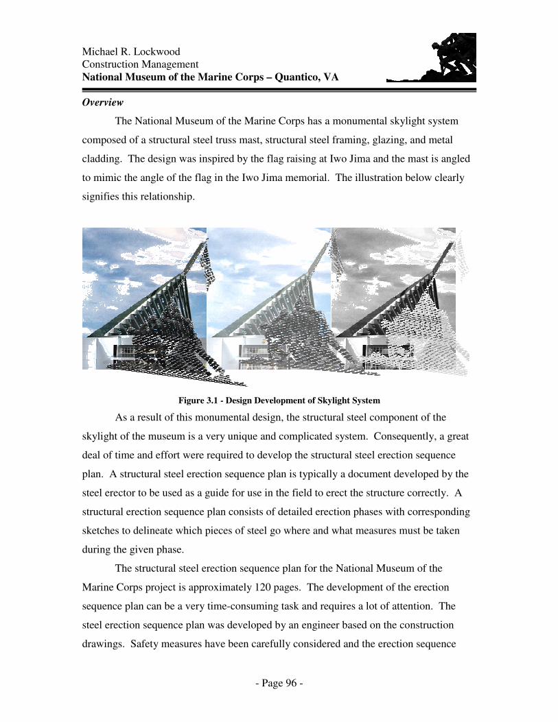
The National Museum of the Marine Corps has a monumental skylight system
composed of a structural steel truss mast, structural steel framing, glazing, and metal
cladding. The design was inspired by the flag raising at Iwo Jima and the mast is angled
to mimic the angle of the flag in the Iwo Jima memorial. The illustration below clearly
signifies this relationship.
Figure 3.1 - Design Development of Skylight System
As a result of this monumental design, the structural steel component of the
skylight of the museum is a very unique and complicated system. Consequently, a great
deal of time and effort were required to develop the structural steel erection sequence
plan. A structural steel erection sequence plan is typically a document developed by the
steel erector to be used as a guide for use in the field to erect the structure correctly. A
structural erection sequence plan consists of detailed erection phases with corresponding
sketches to delineate which pieces of steel go where and what measures must be taken
during the given phase.
The structural steel erection sequence plan for the National Museum of the
Marine Corps project is approximately 120 pages. The development of the erection
sequence plan can be a very time-consuming task and requires a lot of attention. The
steel erection sequence plan was developed by an engineer based on the construction
drawings. Safety measures have been carefully considered and the erection sequence
Michael R. Lockwood Construction Management National Museum of the Marine Corps – Quantico, VA
- Page 97 -
determined in the safest manner possible. The information contained in this document is
very useful to the on-site erection crew; however, it can be cumbersome and difficult to
understand by other individuals on the project.
Therefore, the use of virtual simulation modeling as a tool to assist in the
development of the erection sequence plan, to communicate the plan to other contractors
on-site for coordination purposes and to present to the owner for information purposes
would be beneficial on a given construction project.
2D Structural Steel Erection Planning
The structural steel skylight for the National Museum of the Marine Corps is a
very unique and complex system. As a result, a vast amount of planning had to be
undertaken in order to properly erect the steel components in the fastest and safest
manner possible.
The steel erector developed a “Roof Erection Procedure” document that details
step-by-step how each component is to be erected in sequence. Also included are the
details on temporary falsework, stabilizing guys, and important information regarding the
stability of members and when additional components must be installed before a member
is stable. Another portion of the “Roof Erection Procedure” document are the details of
the lifting lug locations of the steel members.
When all is said and done, the document is composed of approximately 120
pages. These pages vary from a detailed written erection sequence to hand drafted 2-
dimensional sketches of the erection sequence. The following images depict the 2-
dimensional sketches for the steel erection procedure for the Marine Corps project.

Michael R. Lockwood Construction Management National Museum of the Marine Corps – Quantico, VA
- Page 98 -
Figure 3.2 - 2-dimensional sketches from “Roof Erection Procedure”
The development of the steel erection sequence plan for the National Museum of
the Marine Corps took one engineer approximately six months to complete.
3D/4D Virtual Simulation Structural Steel Erection Planning
In an attempt to improve the structural steel erection planning procedure, the use
of 3-dimensional and 4-dimension virtual simulation modeling has been investigated for
the National Museum of the Marine Corps project.
3-dimensional modeling of the National Museum of the Marine Corps was
developed through the use of AutoCAD software. The steel erection model was
developed from the original 3-dimensional Marine Corps model developed by Jason
Reece of Centex Construction. The model was developed to show the entire construction
site including the locations of the following:
• Temporary construction facilities • Access Roads • Steel Staging Areas • Crane Locations • Site boundaries

Michael R. Lockwood Construction Management National Museum of the Marine Corps – Quantico, VA
- Page 99 -
The 3D model of the steel erection for the Marine Corps museum is shown in Figure 3.3.
Figure 3.3 - 3-dimensional model of entire Marine Corps construction site
The model illustrated above is fully interactive and can be easily navigated for
different positions and viewpoints throughout the model. Figure 3.4 shows a close up
view of the skylight steel and crane locations for the erection.
Figure 3.4 - 3-dimensional model of steel erection for Marine Corps project

Michael R. Lockwood Construction Management National Museum of the Marine Corps – Quantico, VA
- Page 100 -
The members were grouped together based on the erection procedure developed
by the contractor. However, this model could have been developed prior to the erection
sequence and grouped together as the plan was developed to aid in this process.
Once the 3-dimensional model was completed, the use of 4-dimensional virtual
simulation modeling was executed. Common Point Project 4D was used to combine the
3-dimensional model developed in AutoCAD and an erection schedule (schedule located
in the appendix) developed in Microsoft Project. The software allows users to link
components of the 3D AutoCAD model and the schedule together.
Once the components are linked, the software can simulate the erection of the
steel. The capabilities of this software continue to grow. The following are some of the
features of the Common Point software: displays percent complete, activity name,
highlighted construction activities, interactive viewpoints, and custom animation. The
4D simulation allows users to control the view and the time scale during the construction
activity. Users can move to any point (in time) during the process and visually see what
activities are under construction, completed, conflicting, etc.
The use of Common Point for the skylight steel erection for the National Museum
of the Marine Corps can be seen in Figure 3.5. When looking at these still images, one
cannot fully experience the 4-dimensional features of this project. The images in Figure
3.5 illustrate the erection sequence.
Figure 3.5 - 4-dimension virtual simulation modeling of steel erection
Michael R. Lockwood Construction Management National Museum of the Marine Corps – Quantico, VA
- Page 101 -
The steel members and cranes highlighted in red are activities that are under
construction at this point in time. Once a member has been erected, the color changes to
the gray color. In an instance when both cranes are red (as in the picture in the upper
right corner), both cranes were required to be used because a member was not laterally
stable until bracing was installed.
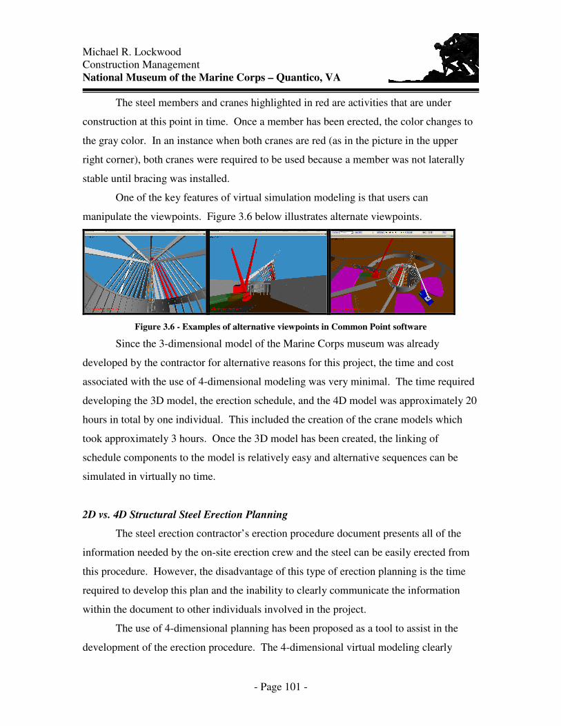
One of the key features of virtual simulation modeling is that users can
manipulate the viewpoints. Figure 3.6 below illustrates alternate viewpoints.
Figure 3.6 - Examples of alternative viewpoints in Common Point software
Since the 3-dimensional model of the Marine Corps museum was already
developed by the contractor for alternative reasons for this project, the time and cost
associated with the use of 4-dimensional modeling was very minimal. The time required
developing the 3D model, the erection schedule, and the 4D model was approximately 20
hours in total by one individual. This included the creation of the crane models which
took approximately 3 hours. Once the 3D model has been created, the linking of
schedule components to the model is relatively easy and alternative sequences can be
simulated in virtually no time.
2D vs. 4D Structural Steel Erection Planning
The steel erection contractor’s erection procedure document presents all of the
information needed by the on-site erection crew and the steel can be easily erected from
this procedure. However, the disadvantage of this type of erection planning is the time
required to develop this plan and the inability to clearly communicate the information
within the document to other individuals involved in the project.
The use of 4-dimensional planning has been proposed as a tool to assist in the
development of the erection procedure. The 4-dimensional virtual modeling clearly

Michael R. Lockwood Construction Management National Museum of the Marine Corps – Quantico, VA
- Page 102 -
communicates the erection procedure and allows the erection contractor to compare and
contrast multiple erection scenarios.
The following images in Figure 3.7 are a direct comparison of the contractor’s 2-
dimensional erection sketches and the 4-dimensional virtual modeling snapshots.
Clearly, the snapshot of the 4D model provides a better representation of the steel pieces
being erected at this stage with viewpoints possible from all angles. The 4-dimensional
model, when used interactively can be even more beneficial in reviewing any conflicts or
safety hazards associated with the erection.
Figure 3.7 - Comparison of 2D vs. 4D of Erection Phase 13
The use of 4-dimensional virtual modeling can be an essential tool for a steel
erection contractor to assist in the development of the structural erection procedure for a
given project. The proposed use of 4-dimensional modeling does not mean the
elimination of the erection procedure document used in the field. The proposed use of
virtual modeling is to assist in the development of that document by reducing the time
required to develop the sequence, to help communicate the erection procedure to other
contractors working on the site, and to present the sequence to the owner and other
individuals associated with the project.

Michael R. Lockwood Construction Management National Museum of the Marine Corps – Quantico, VA
- Page 103 -
Application of 4-dimensional Virtual Simulation
The use of virtual simulation for structural steel erection planning can be used in
three specific areas: (1) assistance in developing erection procedure, (2) coordination
between other trades on construction site, and (3) communication to all individuals
associated with a construction project.
Tool for Developing Erection Procedure
The use of 4-dimensional virtual simulation modeling can be utilized by a steel
erection contractor as a critical tool for developing the structural erection sequence for a
project. The 4-dimensional model allows users to visualize a given erection sequence
and compare and contrast different sequences. The erection contractor can use the 4-
dimensional model in a trial and error scenario for the development of the erection
sequence.
The ability to visualize and change the sequence prior to beginning the actual
erection can be very beneficial and cost saving to the erection contractor. The virtual
model can help the contractor identify potential conflicts and hazards associated with the
erection sequence. Therefore, these conflicts can be addressed prior to facing them in
the field during actual erection.
Trade Coordination
Once the erection sequence has been finalized, the 4-dimensional model can then
be used for trade coordination purposes on the project. The virtual model can be
presented to the other contractors working on the site during the erection phase of a
project. The model could be used to educate the other contractors of the potential hazards
associated with the steel erection procedures, clearly identify the crane locations and
swing radius of the crane, the steel lay down areas and the different areas of a building
that will be erected at a given time.

Michael R. Lockwood Construction Management National Museum of the Marine Corps – Quantico, VA
- Page 104 -
Project Communication
On any project, the owner is very interested and curious as to the means and
methods the contractors are implementing for constructing their project. In most cases, a
prepatory meeting is conducted before the major activities of a project begin. The
meeting generally involves the contractor directly associated with the activity, the general
contractor, the construction manager and the owner’s representative.
Therefore, the use of the 4-dimensional steel erection simulation can be utilized as
a presentation tool to inform this owner and the other individuals as to the contractor’s
plans. This will allow the contractor to address any questions or concerns of the owner
prior to beginning the erection of the project that could potentially impact the erection
procedure if they become apparent during the actual erection of the steel.
Benefit of 4-dimensional Virtual Simulation Modeling
The erection for the skylight steel on the Marine Corps project requires two
cranes: a Liebher 1400 series crane and a smaller truck crane. The Liebher crane was to
be located near the main entrance to the museum between the two concrete walls that
converge on the main entrance. Prior to the crane arrival on-site, the contractors realized
that the counterweight required on the crane to make the critical steel lifts was to extend
approximately 75 feet beyond the end of the crane. As a result of this additional space
needed by the crane and the addition of another phase of the project, the concrete
contractor was forced to re-sequence the concrete activities and leave the R3 wall and a
portion of the C4 wall out until the skylight steel was erected in order to allow enough
space for the crane.
In a situation such as this, the use of 4-dimensional virtual simulation modeling
could have been very beneficial. As the steel erector began to plan out the erection
procedure, the key elements could be in place and scaled to the appropriate dimensions
(i.e. the crane, staging areas, etc.). If 4-dimensional modeling had been used for this
project, the conflict between the crane and the concrete wall could have been identified
earlier in the project and the sequence adjusted accordingly with minimal impact to all
parties.

Michael R. Lockwood Construction Management National Museum of the Marine Corps – Quantico, VA
- Page 105 -
Figure 3.8 from the 4D model below clearly shows the conflict between the crane
and the concrete wall when the crane is positioned in a manner to pick up another piece
of steel from the staging area.
Figure 3.8 - 4D conflict with R3 wall
Figure 3.9 is a snapshot of the 4D model once the conflict was identified and the
concrete work was re-sequenced to allow the crane adequate space to maneuver and
make the required picks from the staging areas.
Figure 3.9 - 4D new sequence of concrete work
This was just one example of a situation that arose on the Marine Corps project
(to date) that may have been prevented and/or identified earlier on had 4-dimensional
virtual simulation modeling been utilized thus reducing the severity of the impact to the
project as a whole.

Michael R. Lockwood Construction Management National Museum of the Marine Corps – Quantico, VA
- Page 106 -
Conclusion
Typically, a structural steel erection plan is developed by an engineer along with
other individuals of a steel erection contractor. The process takes a great deal of time and
is not able to be “tested” prior to the actual steel erection of the project based on the
developed plan. The use of 4-dimensional virtual simulation modeling during the
development process of the steel erection plan can allow the erection contractor to
determine the best erection sequence by allowing them to test and compare different
sequences and scenarios.
The 4-dimensional model can also be used to communicate the potential hazards
and conflicts associated with the steel erection to other contractors on the site. The model
can also be presented to the owner in an informative manner to address any questions or
concerns of the owner prior to beginning the steel erection.
In the instance of the Marine Corps project, and other phased construction
projects, 4-dimensional modeling could be an essential tool to identify conflicts and
concerns with additional phases of a project being added during construction.