Embed Size (px)
Citation preview
Lodam Compressor Protection Module
Technical manualVersion 3.0
SE-G1
Page 2
Contents1. Read this first . . . . . . . . . . . . . . . . . . . . . . . . . . . . . . . . . . . . . . . . . . . . . . . . . . . . . . . . . . . . . . . . . . . . . . . . . . . . . . . . . . . . . . . . . . . . . . . . . 4
1.1. Reading instructions . . . . . . . . . . . . . . . . . . . . . . . . . . . . . . . . . . . . . . . . . . . . . . . . . . . . . . . . . . . . . . . . . . . . . . . . . . 4
1.2. User manual . . . . . . . . . . . . . . . . . . . . . . . . . . . . . . . . . . . . . . . . . . . . . . . . . . . . . . . . . . . . . . . . . . . . . . . . . . . . . . . . . . . . . 4
1.3. Safety . . . . . . . . . . . . . . . . . . . . . . . . . . . . . . . . . . . . . . . . . . . . . . . . . . . . . . . . . . . . . . . . . . . . . . . . . . . . . . . . . . . . . . . . . . . . . . 4
2. General . . . . . . . . . . . . . . . . . . . . . . . . . . . . . . . . . . . . . . . . . . . . . . . . . . . . . . . . . . . . . . . . . . . . . . . . . . . . . . . . . . . . . . . . . . . . . . . . . . . . . . . . . 5
3. Definitions . . . . . . . . . . . . . . . . . . . . . . . . . . . . . . . . . . . . . . . . . . . . . . . . . . . . . . . . . . . . . . . . . . . . . . . . . . . . . . . . . . . . . . . . . . . . . . . . . . . . . 5
4. How to... . . . . . . . . . . . . . . . . . . . . . . . . . . . . . . . . . . . . . . . . . . . . . . . . . . . . . . . . . . . . . . . . . . . . . . . . . . . . . . . . . . . . . . . . . . . . . . . . . . . . . . . . 6
5. Functions . . . . . . . . . . . . . . . . . . . . . . . . . . . . . . . . . . . . . . . . . . . . . . . . . . . . . . . . . . . . . . . . . . . . . . . . . . . . . . . . . . . . . . . . . . . . . . . . . . . . . . 7
5.1. Temperature monitoring . . . . . . . . . . . . . . . . . . . . . . . . . . . . . . . . . . . . . . . . . . . . . . . . . . . . . . . . . . . . . . . . . . . 7
5.2. Rotation direction monitoring . . . . . . . . . . . . . . . . . . . . . . . . . . . . . . . . . . . . . . . . . . . . . . . . . . . . . . . . . . . 7
5.3. Phase failure monitoring . . . . . . . . . . . . . . . . . . . . . . . . . . . . . . . . . . . . . . . . . . . . . . . . . . . . . . . . . . . . . . . . . . 7
6. Examples of application use . . . . . . . . . . . . . . . . . . . . . . . . . . . . . . . . . . . . . . . . . . . . . . . . . . . . . . . . . . . . . . . . . . . . . . . . . . 8
6.1. Connection . . . . . . . . . . . . . . . . . . . . . . . . . . . . . . . . . . . . . . . . . . . . . . . . . . . . . . . . . . . . . . . . . . . . . . . . . . . . . . . . . . . . . . . 8
6.2. Compressor with soft starter . . . . . . . . . . . . . . . . . . . . . . . . . . . . . . . . . . . . . . . . . . . . . . . . . . . . . . . . . . . 9
6.3. Legend for the schematic diagrams . . . . . . . . . . . . . . . . . . . . . . . . . . . . . . . . . . . . . . . . . . . . . . . . . 10
6.4. Technical data . . . . . . . . . . . . . . . . . . . . . . . . . . . . . . . . . . . . . . . . . . . . . . . . . . . . . . . . . . . . . . . . . . . . . . . . . . . . . . . . . 11
7. Drawings . . . . . . . . . . . . . . . . . . . . . . . . . . . . . . . . . . . . . . . . . . . . . . . . . . . . . . . . . . . . . . . . . . . . . . . . . . . . . . . . . . . . . . . . . . . . . . . . . . . . . . . . 12
8. Standards . . . . . . . . . . . . . . . . . . . . . . . . . . . . . . . . . . . . . . . . . . . . . . . . . . . . . . . . . . . . . . . . . . . . . . . . . . . . . . . . . . . . . . . . . . . . . . . . . . . . . 13
9. Trouble shooting . . . . . . . . . . . . . . . . . . . . . . . . . . . . . . . . . . . . . . . . . . . . . . . . . . . . . . . . . . . . . . . . . . . . . . . . . . . . . . . . . . . . . . . . . . . 13
10. Index . . . . . . . . . . . . . . . . . . . . . . . . . . . . . . . . . . . . . . . . . . . . . . . . . . . . . . . . . . . . . . . . . . . . . . . . . . . . . . . . . . . . . . . . . . . . . . . . . . . . . . . . . . . 14
11. Notes . . . . . . . . . . . . . . . . . . . . . . . . . . . . . . . . . . . . . . . . . . . . . . . . . . . . . . . . . . . . . . . . . . . . . . . . . . . . . . . . . . . . . . . . . . . . . . . . . . . . . . . . . . . . 15

Technical manual SE-G1
Page 3
Page 4
1. Read this firstThe contents of this manual are subject to change without
notice. Lodam electronics holds the copyright to this user’s
manual. The user shall follow any instructions given in this
user manual entirely and not only partly. Any non-follow-
ing of this user manual result in exclusion of all warranties,
guarantees, and liabilities. Copyright© 2014 by Lodam
electronics a/s. All Rights Reserved.
Disposing of the parts of the controller:
INFORMATION FOR USERS ON THE
CORRECT HANDLING OF WASTE ELECTRI-
CAL AND ELECTRONIC EQUIPMENT (WEEE)
In reference to European Union directive 2002/96/
EC issued on 27 January 2003 and the related national
legislation, please note that:
1. WEEE cannot be disposed of as municipal waste and
such waste must be collected and disposed of sepa-
rately;
2. The public or private waste collection systems defined
by local legislation must be used. In addition, the equip-
ment can be returned to the distributor at the end of its
working life when buying new
equipment;
3. The equipment may contain hazardous substances:
the improper use or incorrect disposal of such may
have negative effects on human health and on the
environment;
4. The symbol (crossed-out wheeled bin) shown on the
product or on the packaging and on the instruction
sheet indicates that the equipment has been intro-
duced onto the market after 13 August 2005 and that it
must be disposed of separately;
5. In the event of illegal disposal of electrical and elec-
tronic waste, the penalties are specified by local waste
disposal legislation.
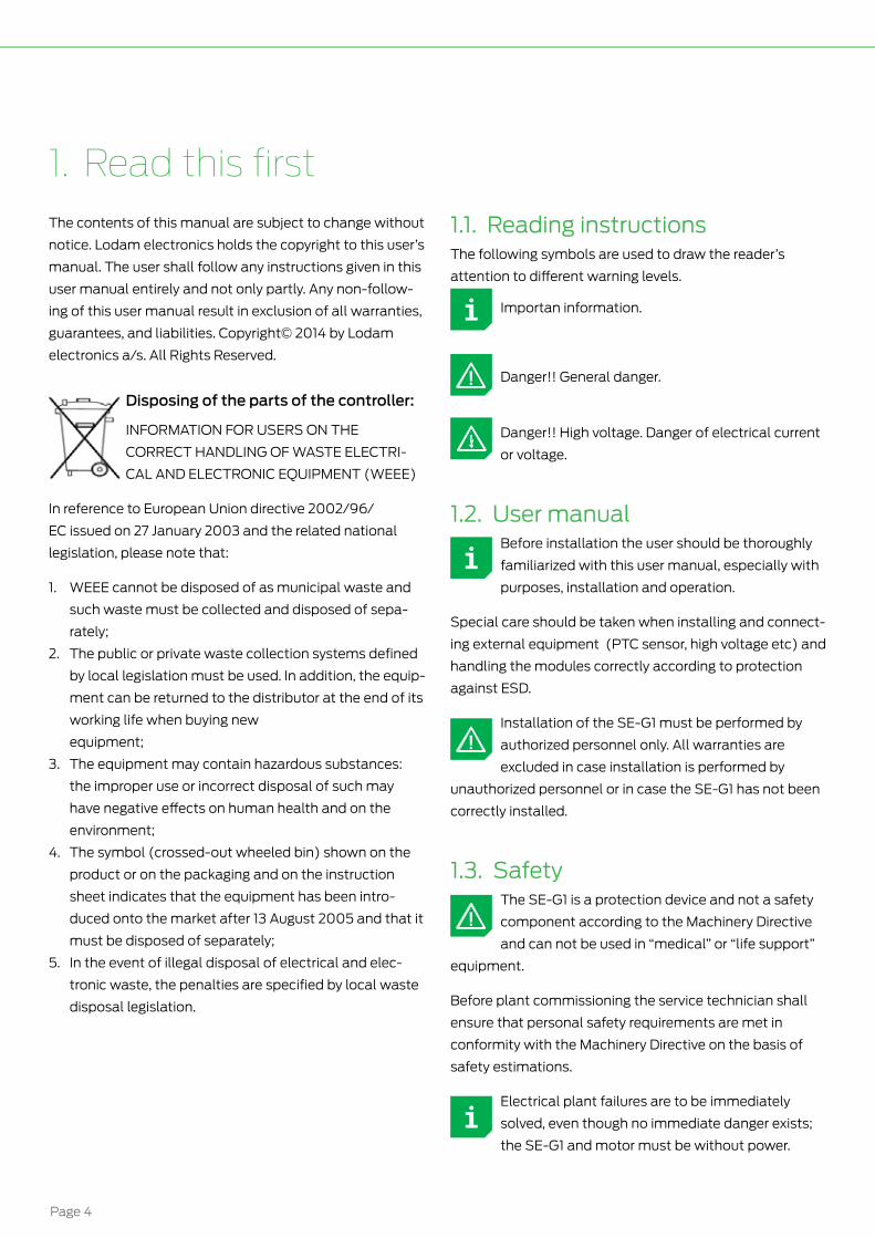
1.1. Reading instructionsThe following symbols are used to draw the reader’s
attention to different warning levels.
Importan information.
Danger!! General danger.
Danger!! High voltage. Danger of electrical current
or voltage.
1.2. User manualBefore installation the user should be thoroughly
familiarized with this user manual, especially with
purposes, installation and operation.
Special care should be taken when installing and connect-
ing external equipment (PTC sensor, high voltage etc) and
handling the modules correctly according to protection
against ESD.
Installation of the SE-G1 must be performed by
authorized personnel only. All warranties are
excluded in case installation is performed by
unauthorized personnel or in case the SE-G1 has not been
correctly installed.
1.3. SafetyThe SE-G1 is a protection device and not a safety
component according to the Machinery Directive
and can not be used in “medical” or “life support”
equipment.
Before plant commissioning the service technician shall
ensure that personal safety requirements are met in
conformity with the Machinery Directive on the basis of
safety estimations.
Electrical plant failures are to be immediately
solved, even though no immediate danger exists;
the SE-G1 and motor must be without power.
Technical manual SE-G1
Page 5
2. GeneralThe protection device SE-G1 is used for protection of scroll
compressors equipped with softstarters. Its relay is used in
the safety chain for the compressor and will open in case
of a failure.
Different scenarios can threaten the lifetime of the com-
pressor where the SE-G1 can protect:
• Overheating: The SE-G1 will protect against overheating by monitoring motor temperature by means of PTC-sen-sors mounted in the motors windings or in the hotgas. In case of overheating, the module will lock out and open the relay.
• Wrong rotation direction: The SE-G1 monitors the rotation direction of the phases at compressor start and will lock out and open the relay in case of wrong rotation direction.
• Phase failure: If a phase is missing at start up, SE-G1 opens the relay for 6 minutes. After this period a start is allowed again. Only a number of retries are allowed before a permanent lock out is performed.
The SE-G1 first starts monitoring of the phases 5 seconds
after start-up to allow the system with the softstarter to
become stable.
3. Definitions
Product range
Definitions
ESD Electro Static Discharge
HW Hardware/electronics
NC Normally Closed (relay)
NO Normally Open (relay)
PTC Positive Temperature Coefficient (sensor element)
Page 6
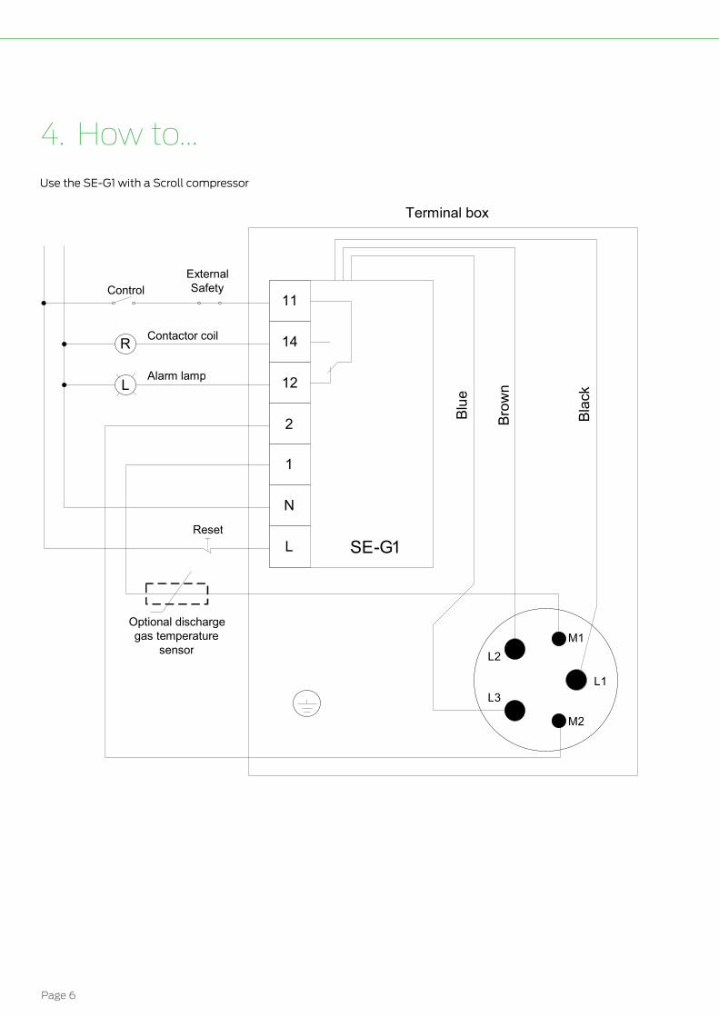
4. How to...Use the SE-G1 with a Scroll compressor
11
14
12
2
1
N
L SE - G 1
L 1 L 2
L 3
M 1
M 2
Blac
k
k Blue
e Brow
n
n
R
L
Control
Contactor coil
Alarm lamp
External Safety
Reset
Optional discharge gas temperature
sensor
Terminal box
Technical manual SE-G1
Page 7
5. FunctionsThe SE-G1 has several monitoring functions which are
listed in the following.
5.1. Temperature monitoringOne of the functions of the SE-G1 is to work as a motor
protection module. By monitoring the resistance in a PTC
sensor, it will open its relay when the resistance of the PTC
sensor increases above the limit as shown below.
The PTC-sensor could for example be according to DIN
44081/82. The resistance of these PTC-sensors is not
linear but give a well-defined steep rise in resistance when
the threshold temperature of the PTC-sensor is reached.
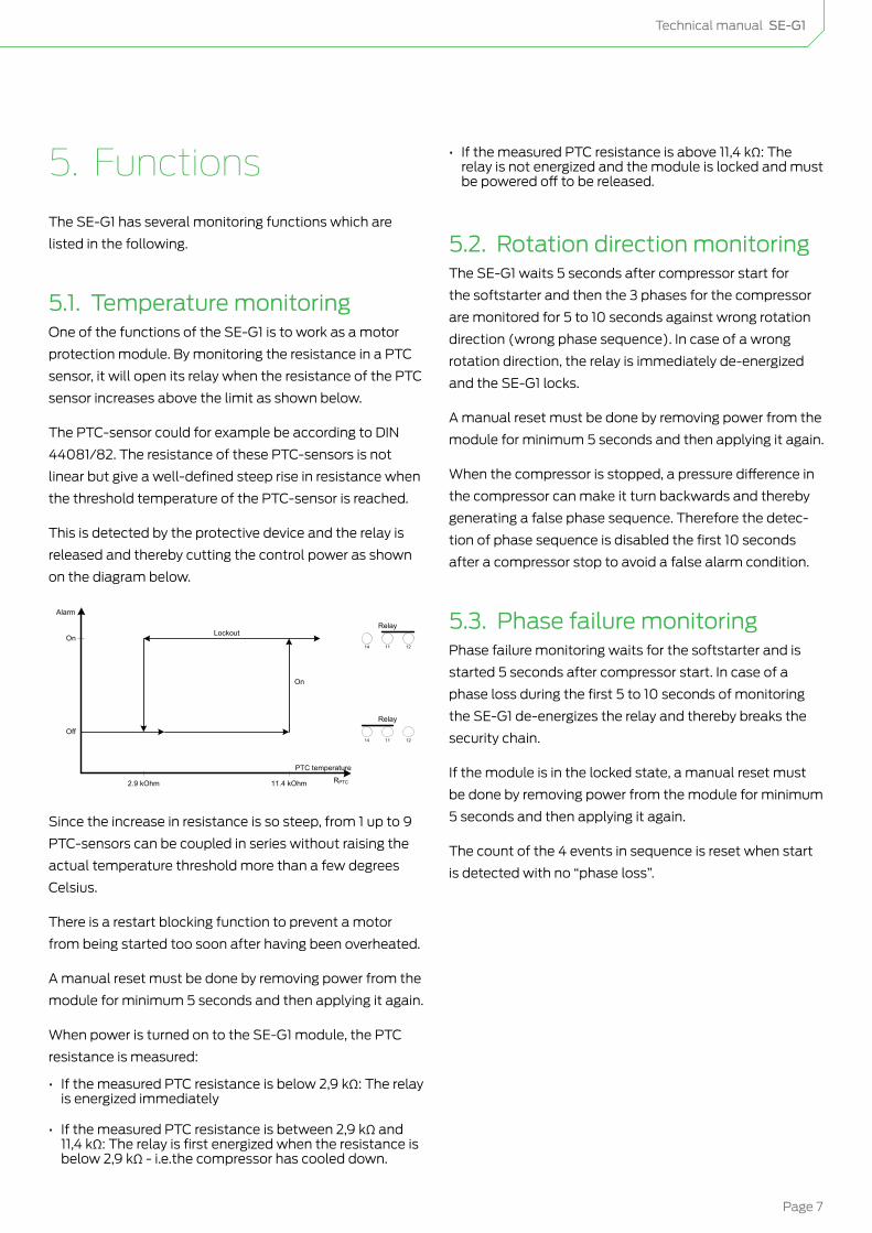
This is detected by the protective device and the relay is
released and thereby cutting the control power as shown
on the diagram below.
On
LockoutOn
Off
Alarm
PTC temperature
RPTC11.4 kOhm2.9 kOhm
14 11 12
14 11 12
Relay
Relay
Since the increase in resistance is so steep, from 1 up to 9
PTC-sensors can be coupled in series without raising the
actual temperature threshold more than a few degrees
Celsius.
There is a restart blocking function to prevent a motor
from being started too soon after having been overheated.
A manual reset must be done by removing power from the
module for minimum 5 seconds and then applying it again.
When power is turned on to the SE-G1 module, the PTC
resistance is measured:
• If the measured PTC resistance is below 2,9 kΩ: The relay is energized immediately
• If the measured PTC resistance is between 2,9 kΩ and 11,4 kΩ: The relay is first energized when the resistance is below 2,9 kΩ - i.e.the compressor has cooled down.
• If the measured PTC resistance is above 11,4 kΩ: The relay is not energized and the module is locked and must be powered off to be released.
5.2. Rotation direction monitoringThe SE-G1 waits 5 seconds after compressor start for
the softstarter and then the 3 phases for the compressor
are monitored for 5 to 10 seconds against wrong rotation
direction (wrong phase sequence). In case of a wrong
rotation direction, the relay is immediately de-energized
and the SE-G1 locks.
A manual reset must be done by removing power from the
module for minimum 5 seconds and then applying it again.
When the compressor is stopped, a pressure difference in
the compressor can make it turn backwards and thereby
generating a false phase sequence. Therefore the detec-
tion of phase sequence is disabled the first 10 seconds
after a compressor stop to avoid a false alarm condition.
5.3. Phase failure monitoringPhase failure monitoring waits for the softstarter and is
started 5 seconds after compressor start. In case of a
phase loss during the first 5 to 10 seconds of monitoring
the SE-G1 de-energizes the relay and thereby breaks the
security chain.
If the module is in the locked state, a manual reset must
be done by removing power from the module for minimum
5 seconds and then applying it again.
The count of the 4 events in sequence is reset when start
is detected with no “phase loss”.
Page 8
6. Examples of application use
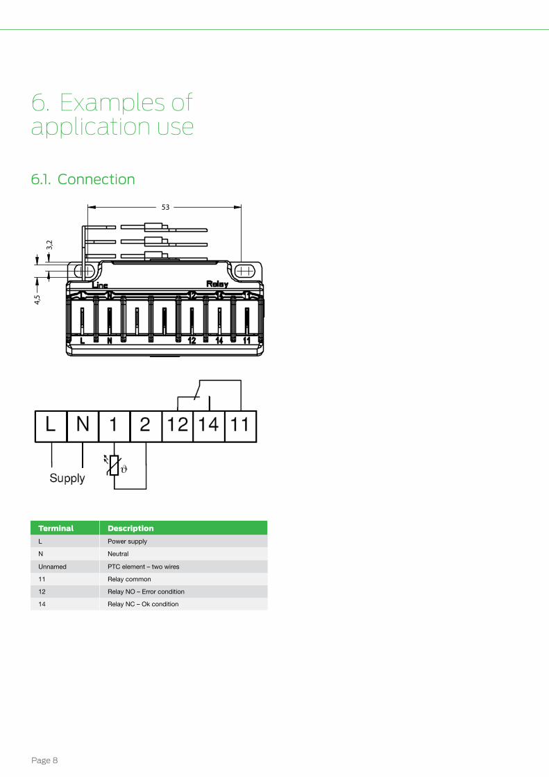
6.1. Connection
3,2
4,5
53
Terminal Description
L Power supply
N Neutral
Unnamed PTC element – two wires
11 Relay common
12 Relay NO – Error condition
14 Relay NC – Ok condition
Technical manual SE-G1
Page 9
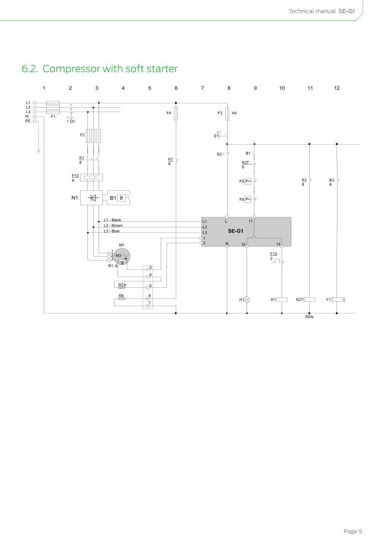
6.2. Compressor with soft starter
L1L2L3NPE
F1 10 Q1
F2
F3 4A
0 1S1
L
21
11
SE-G1
N 12 14
R7
S2
H1
L1L2L3
K18
F138
M1
M3123
R1..6
F132
K2T9
P>F5
P<F6
B1
L1 - BlackL2 - BrownL3 - Blue
10987654321
3
4
5
K16
7
R8
F4
K18
1211
K2T
K18
Y1
K18
300s
ϑB1N1
ϑ
Page 10
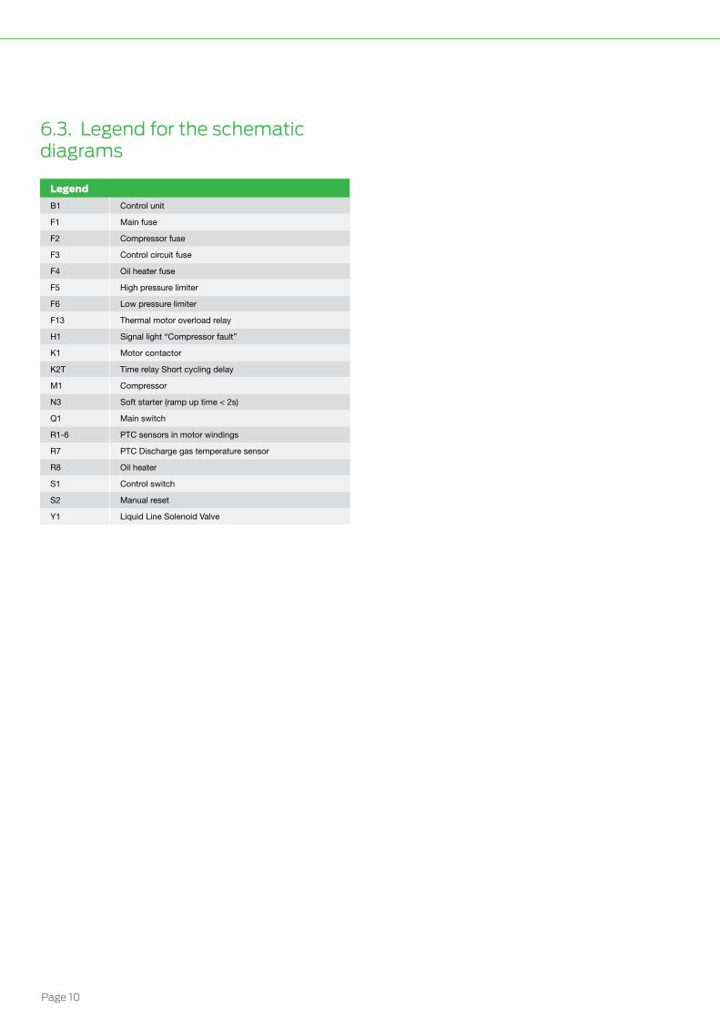
6.3. Legend for the schematic diagrams
Legend
B1 Control unit
F1 Main fuse
F2 Compressor fuse
F3 Control circuit fuse
F4 Oil heater fuse
F5 High pressure limiter
F6 Low pressure limiter
F13 Thermal motor overload relay
H1 Signal light “Compressor fault”
K1 Motor contactor
K2T Time relay Short cycling delay
M1 Compressor
N3 Soft starter (ramp up time < 2s)
Q1 Main switch
R1-6 PTC sensors in motor windings
R7 PTC Discharge gas temperature sensor
R8 Oil heater
S1 Control switch
S2 Manual reset
Y1 Liquid Line Solenoid Valve
Technical manual SE-G1
Page 11
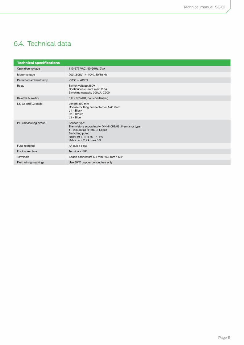
6.4. Technical data
Technical specifications
Operation voltage 110-277 VAC, 50-60Hz, 3VA
Motor voltage 200...600V +/- 10%, 50/60 Hz
Permitted ambient temp. -30°C ~ +60°C
Relay Switch voltage 250V ~ Continuous current max. 2.5A Swiching capacity 300VA, C300
Relative humidity 5% - 95%RH, non condensing
L1, L2 and L3 cable Length 300 mm Connector Ring connector for 1/4” stud L1 – Black L2 – Brown L3 – Blue
PTC measuring circuit Sensor type: Thermistors according to DIN 44081/82, thermistor type: 1 - 9 in series R total < 1,8 kΩ Switching point: Relay off > 11,4 kΩ +/- 5% Relay on < 2,9 kΩ +/- 5%
Fuse required 4A quick blow
Enclosure class Terminals IP00
Terminals Spade connectors 6,3 mm * 0,8 mm / 1/4”
Field wiring markings Use 60°C copper conductors only
Page 12
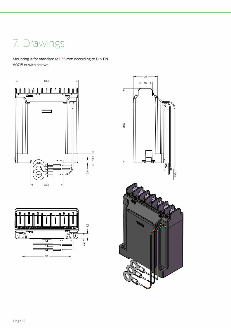
7. DrawingsMounting is for standard rail 35 mm according to DIN EN
60715 or with screws.
35,3
10,
0
3,0
68,3
80,
5
16
26
3,2
4
,5
53
REVISION HISTORYRevision: Date: Reference: Changes from last revision:
1,0A 2012-02-17 KSJ First release
Sach-Nr. / Ident-No.
Anschlus Spannung / Supply Voltage
34704301 AC. 50/60Hz. 115-230VAC.
1,0AConsept Dwg.Revision:State:
Size:
Item no.:
Note:
Item Description:
Project / Product Name:
A3
Dimensions are in mm.Do not scale drawing
General tolerance accuracy:
Sheet:Weight:Scale:
ISO 2768-mK
Proprietary and confidentialThe information contained in this
drawing is the sole property ofLodam electronics A/S.
Any reproduction in part or as a wholewithout the written permission of
Lodam electronics A/S is prohibited.
Lodam electronics A/SKærvej 77
DK-6400 SønderborgPhone: (+45) 7342 3737
Fax: (+45) 7342 3730www.Lodam.com
525601 - SE-E1-
SE-G1 With Spade Connectors
SE-G1 With Spade Connectors
KSJ 2012-02-17
73.56g
-
SE-G1 With Spade Connectors
Surface Treatment:
1 of 1
Checked:
Drawn by:
Date:Name:
Material:
1:1
Technical manual SE-G1
Page 13
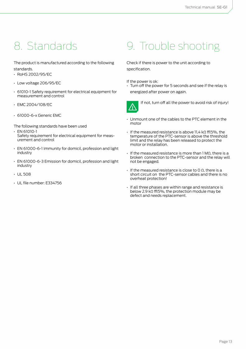
8. StandardsThe product is manufactured according to the following
standards.• RoHS 2002/95/EC
• Low voltage 206/95/EC
• 61010-1 Safety requirement for electrical equipment for measurement and control
• EMC 2004/108/EC
• 61000-6-x Generic EMC
The following standards have been used• EN 61010-1
Safety requirement for electrical equipment for meas-urement and control
• EN 61000-6-1 Immunity for domicil, profession and light industry
• EN 61000-6-3 Emission for domicil, profession and light industry
• UL 508
• UL file number: E334756
9. Trouble shootingCheck if there is power to the unit according to
specification.
If the power is ok:• Turn off the power for 5 seconds and see if the relay is
energized after power on again.
If not, turn off all the power to avoid risk of injury!
• Unmount one of the cables to the PTC element in the motor
• If the measured resistance is above 11,4 kΩ ±5%, the temperature of the PTC-sensor is above the threshold limit and the relay has been released to protect the motor or installation.
• If the measured resistance is more than 1 MΩ, there is a broken connection to the PTC-sensor and the relay will not be engaged.
• If the measured resistance is close to 0 Ω, there is a short circuit on the PTC-sensor cables and there is no overheat protection!
• If all three phases are within range and resistance is below 2.9 kΩ ±5%, the protection module may be defect and needs replacement.

Page 14
10. IndexC
Compressor with soft starter 9
Connection 8
D
Definitions 5
Drawings 12
F
Functions 7
H
How to... 6
M
Motor voltage 11
Mounting 12
O
Operation voltage 11
P
Phase failure monitoring 7
R
Rotation direction monitoring 7
S
Standards 13
T
Technical data 11
Temperature monitoring 7
Trouble shooting 13

Technical manual SE-G1
Page 15
11. Notes

Innovative and energy saving climate controlWhen it comes to climate control Lodam is one of the most experienced you can turn to. For more than four decades we have developed, produced and implemented electronic solutions dedicated to optimising applications like:
• Compressors• Condensing units• Heat pumps• Air conditioning• Refrigerated truck and trailer• Reefer containers
We know the importance of reliable, energy-efficient operation – and constantly push techno-logical boundaries to bring you the most innovative and forward-thinking solutions.
As part of the BITZER Group we are backed by one of the world’s leading players in the refrigeration and air conditioning industry. This alliance provides us with extensive network and application knowhow and allows us to stay at the forefront of climate control innovation. And to help ensure comfortable surroundings for humans and reliable protection of valuable goods anywhere in the world.
Lodam electronics a/sKærvej 776400 SønderborgDenmark
Tel. +45 7342 3737Fax +45 7342 [email protected]
For more information visit:
www.lodam.com
23
-01-
20
15 C
on
ten
ts a
re s
ub
ject
to
ch
an
ge
wit
ho
ut
no
tice
.