Embed Size (px)
Citation preview
Department of Environmental Protection
STD-07092501.4.0 Page 1 of 26
Logical Data Modeling Standard
PurposeThis document specifies the Florida Department of Environmental Protection’s (DEP) Logical Data Modeling Standard. The purpose of this standard is to ensure that DEP logical data models and associated application data modeling deliverables have a consistent look and feel.
ScopeThis standard applies to all database schema development at DEP.
Standard1. All DEP database schemas shall follow Oracle database standards and guidelines found at
the Oracle Technology Network website.
2. Developers shall follow the Logical Data Modeling Specifications which is included as Appendix A to this standard. This specification provides technical guidelines, definitions, and references, including database naming standards, logical model diagram layout, and instructions for naming entities and attributes. A list of the Oracle Reserved Words is included in Appendix B to this standard.
3. All DEP database schemas shall follow the DEP Database Object Coding Standard (STD-14121501).
4. All DEP database schemas shall follow the DEP Physical Data Modeling Standard (STD-09061805).
Deviation from Use
Any deviation from this standard must be approved by approved by the Enterprise Application Services or the Portfolio Management Services Program Administrator and documented in associated project documentation. The DEP Contract Manager shall also document and approve any deviations for contracted projects.
STD-07092501.4.0Logical Data Modeling Standard
Page 1 of 26

AppendicesAppendix A: Logical Data Modeling SpecificationsAppendix B: Attribute Class Words
Approvals
Approved by Warren Sponholtz, CIO 4/21/2016Approval Date
STD-07092501.4.0Logical Data Modeling Standard
Page 2 of 26
Appendix A: Logical Data Modeling Specifications

Table of ContentsPURPOSE........................................................................................................................................................... 1SCOPE................................................................................................................................................................ 1STANDARD........................................................................................................................................................ 1DEVIATION FROM USE..................................................................................................................................... 1APPROVALS...................................................................................................................................................... 2INTRODUCTION........................................................................................................................................... 4GRANDFATHER CLAUSE.......................................................................................................................... 4GENERAL STANDARDS............................................................................................................................. 4
DEP Supported Modeling Tool........................................................................................4Third Normal Form..........................................................................................................5Location Data Standards..................................................................................................5
ENTITIES........................................................................................................................................................ 5
Entity Name......................................................................................................................5Entity Short Name............................................................................................................6Entity Comment................................................................................................................7Enterprise Code Entity Usage..........................................................................................7
REQUIRED ENTITY ATTRIBUTES.......................................................................................................... 8
Transactional Entity Attributes.......................................................................................8Code Entity Attributes......................................................................................................9Processing Entity Attributes – TEMP and RPT.............................................................10Processing Entity Attributes – HS (Audit)....................................................................10
BUSINESS ENTITY ATTRIBUTES......................................................................................................... 11
Atomic Attribute.............................................................................................................11Attribute Naming............................................................................................................11Attribute Class Words....................................................................................................12Indicator Attribute - Class Word Suffix IND.................................................................12Attribute Sequencing.....................................................................................................12Attribute Data Type........................................................................................................12Attribute Comment........................................................................................................ 13Foreign Key Attribute.................................................................................................... 13
ENTITY UNIQUE IDENTIFIERS............................................................................................................. 14
Entity Primary Key.........................................................................................................14Entity Unique Key...........................................................................................................14
ENTITY RELATIONSHIPS........................................................................................................................ 14LOGICAL MODEL DIAGRAM.................................................................................................................. 15
Logical Model Diagram Entity Placement.....................................................................16Entity Formatting...........................................................................................................17
STD-07092501.4.0Appendix A: Logical Data Modeling Specifications
Page 4 of 26
Logical Model Diagram Entity Relationship Placement...............................................17ATTRIBUTE CLASS WORDS............................................................................................................................. 2
STD-07092501.4.0Appendix A: Logical Data Modeling Specifications
Page 5 of 26
INTRODUCTION
The phases of model development begin with Needs Analysis followed by a high-level definition of the projected data model. The development team uses the business model to define the logical implementation of the system. The logical implementation is known as an Entity Relationship Diagram (ERD). The information contained in the ERD is limited; it is intended to be just enough to define the groupings needed to store the related data. As development continues the ERD is transformed into a Logical Data Model (LDM) that represents a more defined structure which includes the next level of details. For the LDM to be considered complete details such as attributes, primary keys, unique keys, relationships, and documentation must be provided. After completion of the LDM, the model is transformed into the Physical Data Model (PDM) which represents the database structure and includes database scripts. Project teams may consult with the Database Administration (DBA) staff in the Office of Technology and Information Systems (OTIS) during the logical schema design. The OTIS DBA staff shall review and approve all LDMs.
The output from the initial phase of modeling, the ERD, is not reviewed due to its limited content. The ERD is expanded on as development continues and results in the more detailed LDM. This standard governs the expectations that must be met for the LDM. A complete LDM consists of two components:
1. The Logical Schema Diagram which is the “picture of the Logical Data elements” (usually the entities and how they related to each other).
2. The Entity and Attribute Report which consist of documentation of the entities, attributes, and associated relationships and primary identifiers.
GRANDFATHER CLAUSE
Existing legacy applications that are grandfathered with respect to changes in the standards will be brought into compliance over time as enhancement releases are fielded for a particular application. Maintenance releases are specifically waived with respect to a standards review.
GENERAL STANDARDS
DEP Supported Modeling Tool
Conceptual, Logical and Physical Models must be developed using the Oracle SQL Developer Data Modeler tool. All development teams must use Oracle SQL Developer Data Modeler and the approved DEP code versioning repository – Subversion (SDI). The use of any other modeling tool/repository is not authorized.
STD-07092501.4.0Appendix A: Logical Data Modeling Specifications
Page 6 of 26
Third Normal Form
The ERD component of the LDM must be in at least third normal form (Boyce-Codd, fourth, and fifth normal form are also acceptable).
Location Data Standards
The established Location Data Standards will be adhered to for geospatial objects. Adherence to these supplementary standards is mandatory. Models including geospatial objects will be sent to Geographic Information Systems (GIS) for review.
ENTITIES
The entity definition specifies what type of data is stored and specifies the pieces of data that make the record unique. Entities in the Logical Data Model must be thoroughly documented in order to transform the model to the Physical Data Model.
Entity Name
An entity name must be singular. The following rules apply to entity names: An entity name must be a maximum of 30 characters long. An entity name must be made up of one to five words. Only singular nouns and modifiers are to be used for an entity name. An entity name must contain only alphabetical characters and spaces. An entity name must not contain numeric values. An entity name must not contain hyphens or underscores between the words if more than
one word is present. An entity name must not contain the Oracle Reserved Words. An entity name must include an Entity Class Word when the entity represents the following
data:o Code or Lookup Values – The name of a code entity must end in the Entity Class
Word of “CODE” preceded by a space.o History Tracking – The name of the “history” entity must end in the Entity Class
Word of “HS” preceded by a space.o Reporting – The name of the “reporting” entity must end in the Entity Class Word of
“RPT” preceded by a space.o Temporary – The name of the “temporary” entity must BEGIN in the Entity Class
Word of “TEMP” followed by a space.
Guideline: The logical model allows a larger name length so that abbreviations can be avoided for clarity sake in the business model. The PDM however, is limited by the Oracle thirty character naming constraint so longer names will be truncated. . If an entity is to be referenced by a child entity consider shortening the entity name to allow for the “alias” or
STD-07092501.4.0Appendix A: Logical Data Modeling Specifications
Page 7 of 26
“short name” that is appended when forming the foreign key column name. The entity name must be shortened before transforming to the PDM to avoid truncation.
Entity Short Name
An entity short name is also known as an “alias”. The entity alias is a unique identifier across all DEP entities allowing for tracing of relationships within a model or across multiple application models. Oracle SQL Developer Data Modeler uses the short name in the generation of foreign key column names and names of constraints, indexes, sequences, etc.
The following rules apply to the Entity Short Name:
Each entity must have an entity short name. An entity short name must be a unique combination of up to six letters. An entity short name must not be an Oracle Reserved Word, an Entity Class Word, or an
Attribute Class Word. The entity short name must be unique among all existing DEP enterprise Oracle short
names. Guidelines for determining a valid short name are:o Currently reserved short names are stored in the ORADEV database instance,
BIS_LIB schema, SHORT_NAMES table.o A candidate entity short name is subject to change until reserved. Since multiple
Application Development Teams must reserve short names, to prevent problems during development, Database Administration recommends that you submit your candidate short names as soon as possible to the DBA section when they are finalized.
o Once a candidate entity short name is established, the Application Development Team must contact the Database Administration Section who will record (reserve) these short names and confirm they have been reserved. This process changes the short name from a candidate to reserved status.
o If the one word entity name is six characters or fewer, use the first three letters of the name as the short name. If that short name is has already been reserved, add one letter of the word until it is unique.
o If the one word entity name consists of more than six characters, use the first three letters of the entity name as the short name. If that short name is not unique, add one letter of the word, up to the sixth letter, until it is unique.
o If the entity name is more than one word, use the first character of each word up to six characters.
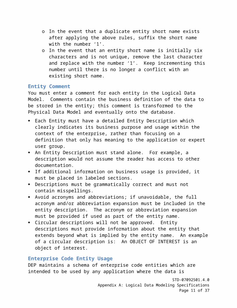
o In the event that a duplicate entity short name exists after applying the above rules, suffix the short name with the number ‘1’.
o In the event that an entity short name is initially six characters and is not unique, remove the last character and replace with the number ‘1’. Keep incrementing this number until there is no longer a conflict with an existing short name.
STD-07092501.4.0Appendix A: Logical Data Modeling Specifications
Page 8 of 26
Entity CommentYou must enter a comment for each entity in the Logical Data Model. Comments contain the business definition of the data to be stored in the entity; this comment is transformed to the Physical Data Model and eventually onto the database.
Each Entity must have a detailed Entity Description which clearly indicates its business purpose and usage within the context of the enterprise, rather than focusing on a definition that only has meaning to the application or expert user group.
An Entity Description must stand alone. For example, a description would not assume the reader has access to other documentation.
If additional information on business usage is provided, it must be placed in labeled sections.
Descriptions must be grammatically correct and must not contain misspellings. Avoid acronyms and abbreviations; if unavoidable, the full acronym and/or abbreviation
expansion must be included in the entity description. The acronym or abbreviation expansion must be provided if used as part of the entity name.
Circular descriptions will not be approved. Entity descriptions must provide information about the entity that extends beyond what is implied by the entity name. An example of a circular description is: An OBJECT OF INTEREST is an object of interest.
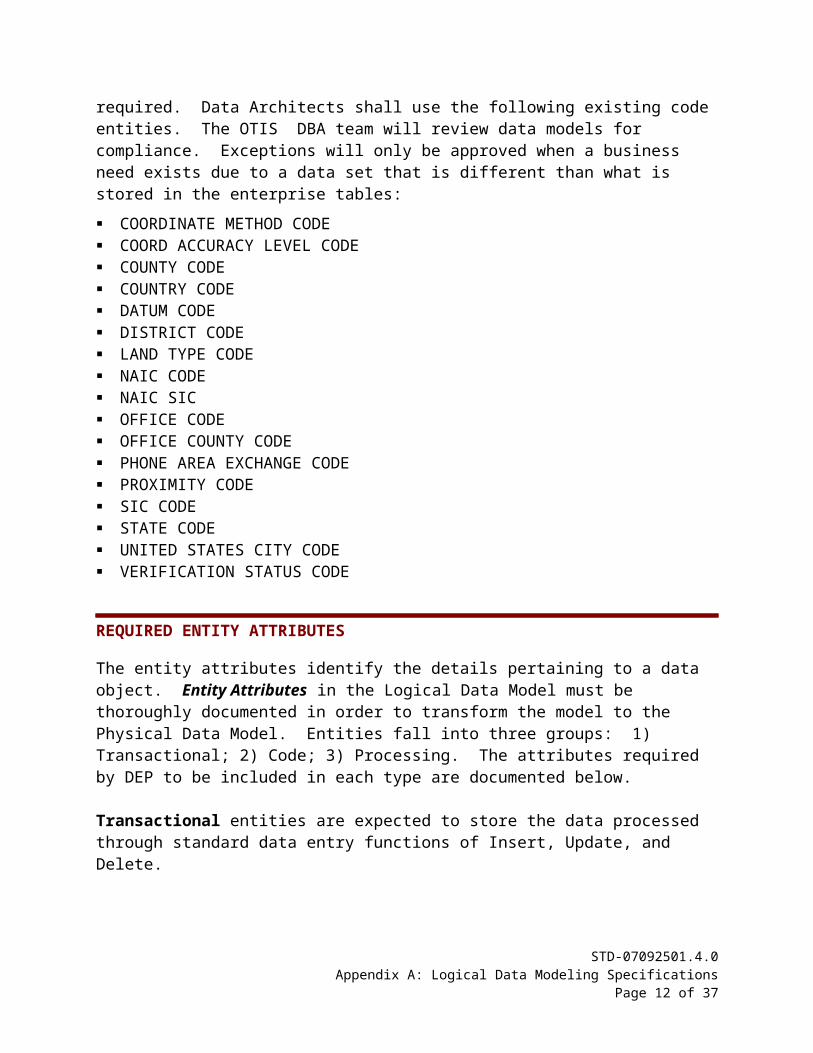
Enterprise Code Entity UsageDEP maintains a schema of enterprise code entities which are intended to be used by any application where the data is required. Data Architects shall use the following existing code entities. The OTIS DBA team will review data models for compliance. Exceptions will only be approved when a business need exists due to a data set that is different than what is stored in the enterprise tables:
COORDINATE METHOD CODE COORD ACCURACY LEVEL CODE COUNTY CODE COUNTRY CODE DATUM CODE DISTRICT CODE LAND TYPE CODE NAIC CODE NAIC SIC OFFICE CODE OFFICE COUNTY CODE PHONE AREA EXCHANGE CODE PROXIMITY CODE SIC CODE STATE CODE UNITED STATES CITY CODE VERIFICATION STATUS CODE
STD-07092501.4.0Appendix A: Logical Data Modeling Specifications
Page 9 of 26
REQUIRED ENTITY ATTRIBUTES
The entity attributes identify the details pertaining to a data object. Entity Attributes in the Logical Data Model must be thoroughly documented in order to transform the model to the Physical Data Model. Entities fall into three groups: 1) Transactional; 2) Code; 3) Processing. The attributes required by DEP to be included in each type are documented below.
Transactional entities are expected to store the data processed through standard data entry functions of Insert, Update, and Delete.
Code entities are expected to store values usually set up and maintained by an application administrator to be used in drop-down lists.
Processing entities contain data that is aggregated or manipulated in some way by the application in order to perform some business function. Examples are report result tables, data audit tables (also known as history tables), and temporary tables created on-the-fly to produce a data set.
Transactional Entity AttributesThe following attributes must be included in all transactional entities.
Attribute Name Data Type Required Length Optional<ENTITY NAME> KEY
e.g. PAYMENTS primary key attribute isPAYMENT KEY
PAYMENT HS primary key attribute is PAYMENT HS KEY
Number Number(10)
Number(10) should be used in all cases. Exceptions will be allowed if a business need exists requiring a smaller or larger number.
No
CREATE USER NAME Varchar2 30 NoCREATE TS Date NoMODIFY USER NAME Varchar2 30 YesMODIFY TS Date Yes
Table 1 – Transactional Entity Attributes
STD-07092501.4.0Appendix A: Logical Data Modeling Specifications
Page 10 of 26
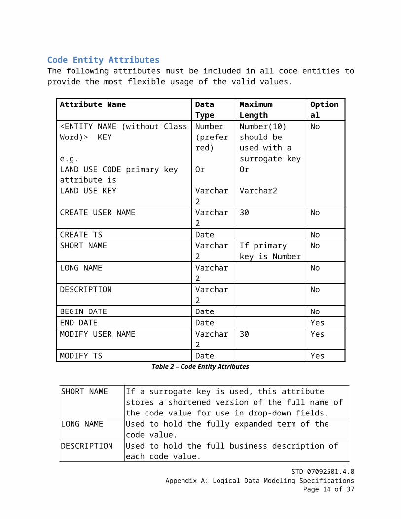
Code Entity AttributesThe following attributes must be included in all code entities to provide the most flexible usage of the valid values.
Attribute Name Data Type Maximum Length Optional<ENTITY NAME (without Class Word)> KEY
e.g. LAND USE CODE primary key attribute isLAND USE KEY
Number(preferred)
Or
Varchar2
Number(10) should be used with a surrogate key Or
Varchar2
No
CREATE USER NAME Varchar2 30 NoCREATE TS Date NoSHORT NAME Varchar2 If primary key is
NumberNo
LONG NAME Varchar2 NoDESCRIPTION Varchar2 NoBEGIN DATE Date NoEND DATE Date YesMODIFY USER NAME Varchar2 30 YesMODIFY TS Date Yes
Table 2 – Code Entity Attributes
SHORT NAME If a surrogate key is used, this attribute stores a shortened version of the full name of the code value for use in drop-down fields.
LONG NAME Used to hold the fully expanded term of the code value.DESCRIPTION Used to hold the full business description of each code value.
Table 3 – Code Entity Attribute Definitions
STD-07092501.4.0Appendix A: Logical Data Modeling Specifications
Page 11 of 26
Processing Entity Attributes – TEMP and RPTThe following attributes must be included in TEMP and RPT processing entities.
Attribute Name Data Type Maximum Length Optional<ENTITY> KEY
e.g. PAYMENT TRACKING RPT primary key attribute isPAYMENT TRACKING RPT KEY
TEMP PIVOT TABLE DATAprimary key attribute isTEMP PIVOT TABLE DATA KEY
Number Number(10) should be used with a surrogate key
No
DATA LAST UPDATED DATE Date NoTable 4 – TEMP and RPT Processing Entity Attributes
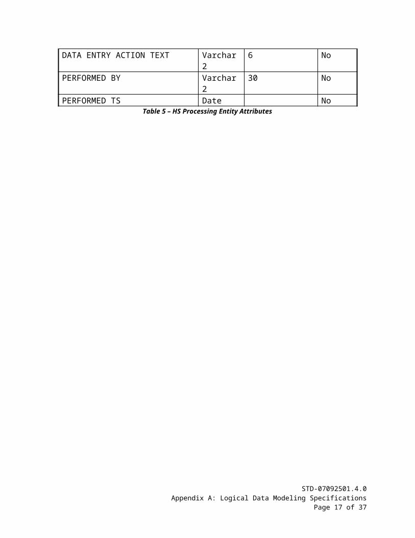
Processing Entity Attributes – HS (Audit)The following attributes must be included in HS (Audit) entities. Entities storing audit data should include attributes defined by the business unit as important for audit purposes. It is acceptable to base the audit entity on the primary entity and track all attributes. In addition to the standard attributes consider adding attributes to track the data entry function that was performed (INSERT, UPDATE, DELETE) as well as the performed by and performed date.
Attribute Name Data Type Maximum Length Optional<ENTITY> KEY
e.g. PAYMENT TRACKING HSprimary key attribute isPAYMENT TRACKING HS KEY
Number Number(10) should be used with a surrogate key
No
DATA ENTRY ACTION TEXT Varchar2 6 NoPERFORMED BY Varchar2 30 NoPERFORMED TS Date No
Table 5 – HS Processing Entity Attributes
STD-07092501.4.0Appendix A: Logical Data Modeling Specifications
Page 12 of 26

BUSINESS ENTITY ATTRIBUTES
Business Entity Attributes in the LDM must follow specific guidelines to ensure data integrity. The following are standards applicable to attributes:
Atomic AttributeAttributes are properties of the owning entity and as such must convey a singular atomic fact about the entity. For example, the code Report Frequency could have a value of ‘D’ for daily or ‘W’ for weekly. These are atomic facts and cannot further be broken down. However a code Type Frequency with a value of ‘DSUM’ meaning daily summary establishes two separate facts, one that it is a daily occurrence and two that it is a summary report. In reality you have two separate facts, the frequency and the type of report. As such two separate attributes should be use .
Attribute NamingEntities described in an ERD do not require attributes. All entities in a LDM must contain at least one attribute.
The following rules apply to the Entity Attribute names:
The attribute name must be made up of one to five words followed by one Attribute Class Word used to clarify the attribute if the information cannot be obtained from the attribute name.
An attribute name must not exceed 30 characters. When an attribute name is only one word, it must not be an Oracle Reserved Word. The attribute name must be singular and contain no hyphens or underscores.
Guideline: An attribute name of PROCESS DATE with an Oracle data type of DATE may be either a date with time or a date without time. To clarify:
The attribute name should be <Attribute Name> DATE with the Oracle data type of DATE if the business does not require the time. e.g. (MM/DD/YYYY).
The attribute name should be <Attribute Name> TS with the Oracle data type of DATE if the business requires the time without the time zone or only down to the second. e.g. (MM/DD/YYYY HH:MI:SS PM).
Audit attributes such as CREATE TS and MODIFY TS should always be the Oracle data type of DATE and store the date with time down to the second.
The attribute name should be <Attribute Name> TS with the Oracle data type of TIMESTAMP if the business requires the time with the time zone or down to the millisecond. e.g. (MM/DD/YYYY HH:MI:SS:MS PM Eastern Time Zone).
STD-07092501.4.0Appendix A: Logical Data Modeling Specifications
Page 13 of 26
Attribute Class WordsAttributes must be suffixed with an Attribute class word; the Attribute Class Word List is contained in Appendix B.
Indicator Attribute - Class Word Suffix INDSome business models require attributes that store data intended as an indicator used to determine when a corresponding action must occur. Indicators never contain more than two values and should be clearly defined so the reader can determine what the values mean. An example of an indicator attribute is DATA SUCCESSFULLY LOADED IND where the only acceptable values are Y (Yes) and N (No). In this example it is very clear what the column is intended to flag and what the values represent.
Indicator Attributes must: Have a format of VARCHAR2(1) NOT NULL. Have only two states and cannot have a NULL state. Be named so that the value contained in the fields is clearly understood. Avoid use of 0 and 1 values as indicators.
Attribute SequencingAttributes within an entity must be ordered to allow for easy maintenance of the model and easier reading by both developer and business unit. The following attribute sequencing should be applied to the Logical Data Model, this sequencing is transformed to the Physical Model and to the associated database DDL:
The Primary Key (PK) attribute must be displayed first.
The required Foreign Key (FK) attributes, if they exist, must be displayed after the Primary Key attribute in logical order of importance.
The audit attributes CREATE USER NAME and CREATE TS must be displayed next and in the same order in all entities.
The required business attributes are displayed next in logical business order. For example, the attributes for an address would be ordered as ADDRESS 1, ADDRESS 2, CITY, STATE, ZIP5, and ZIP4.
The optional business attributes are displayed next in logical business order. The optional audit attributes, MODIFY USER NAME and MODIFY TS are displayed last and
must be in the same order in all entities.
Attribute Data TypeDuring development of the Entity Relationship Model (ERD) attribute data types are usually not specified. For the Logical Model, attributes must be defined with the appropriate data type for the data being stored. This documentation is required for transforming the model to the Physical Data Model.
Assigning of the data type to the Attributes must meet the following requirements:STD-07092501.4.0
Appendix A: Logical Data Modeling SpecificationsPage 14 of 26

A data type must include the maximum length and, if applicable, the precision and scale. Audit attributes CREATE USER NAME and MODIFY USER NAME must be VARCHAR2 with a
length of 30 (VARCHAR2(30)). Audit attributes CREATE TS and MODIFY TS must be DATE. The use of ANSI data types of DECIMAL, INTEGER, INT, SMALLINT, CHARACTER, CHARACTER
VARYING, CHAR VARYING, REAL and DOUBLE PRECISION is not allowed. The data type of CHAR, while supported by Oracle, is not authorized as an acceptable type.
A data type of VARCHAR2 (n) with the specified length must be used instead of CHAR.
Attribute CommentAll attributes must have comments. The attribute comment is transformed to the Physical Model and then to the DDL that are used to create the tables on the database. The following rules apply to Attribute Comments:
Comments are limited to a maximum of 4000 characters in length. Comments must clearly indicate the attributes’ meaning within the context of the
enterprise rather than focusing on a comment that only has meaning to the application expert user group.
The comment must define the business meaning; as such the system analyst/end users are the best source for a comment that avoids techno-jargon.
Comments must stand alone. A comment would not assume the reader has access to other documentation.
All comments must assume that the reader does not have direct knowledge of the application, that is, they will be enterprise comments rather than narrowly focused application comments.
Circular comments must be avoided. In other words they should provide information about the attribute that extends the business definition beyond what is implied by the attribute name.
Foreign Key AttributeWhen relationships are created between entities the modeling tools use a line between the entities to represent the Foreign Key Attribute. The following rules apply:
The Foreign Key Attribute that corresponds to the relationship must not be added manually to the entity, SQL Developer Data Modeler automatically adds the attribute after the relationship is defined.
The Data Architect must manually adjust the attribute sequence within the attribute list so that it meets the Attribute Sequencing rule.
The relationship representing the attribute may be used in a Unique Key. When the Logical Model is transformed to the Physical Model the modeling tool creates the corresponding Foreign Key column in the table following the approved naming standards. The naming standard for Foreign Key columns is defined in the Physical Data Modeling Standard.
STD-07092501.4.0Appendix A: Logical Data Modeling Specifications
Page 15 of 26

ENTITY UNIQUE IDENTIFIERS
The Data Architect must define unique identifiers for each entity. The unique identifiers ensure data integrity by preventing duplicate records and providing a data value used to retrieve a single row of data.
Entity Primary KeyOne attribute must be defined as the Primary Key for each entity; the Primary Key ensures a uniqueness across all data stored in the entity. The Data Architect should make this decision based on the technology used to build the application. Current Java Persistence Layer Architecture works best with a surrogate key for all entities. The following applies to this standard:
A surrogate key generated by an Oracle sequence is the preferred form of Primary Key. Primary Key attributes intended to be surrogate keys must be of data type NUMBER(10). For code entities it is an option to use the code value as the Primary Key. The Primary Key attribute class word is always KEY even if the code value is used instead of
a surrogate key. e.g. PAYMENT KEY or COUNTY KEY.
Entity Unique KeyIn addition to the Primary Key, one or more attributes may be defined as the Unique Key for an entity. A Unique Key is not required but is recommended. While the Primary Key ensures a uniqueness across all data stored in the entity, usually through an Oracle generated sequence, the Unique Key ensures a uniqueness based on specific business values. For example, a sequence is used for the primary key when storing a receipt of a payment to DEP. The sequence cannot ensure that the same payment record is not stored multiple times. To ensure data integrity the Data Architect may add a unique key based on the Remitter Name, Payment Amount, and Payment Date. The following apply to Unique Keys:
If a Unique Key is defined, one or more attributes must be attached. The Primary Key attribute, if a surrogate key, cannot be part of the Unique Key. Business attributes included in a Unique Key must end in the Class Word Suffix of ID. Relationships representing Foreign Key attributes may be included in a Unique Key.
ENTITY RELATIONSHIPS
During the analysis phase of model development, the Data Architect identifies entities and how they are related to each other. For example, a DEPARTMENT entity is related to the EMPLOYEE entity since a department usually consists of one or more employees. Entity Relationships consist of several elements that govern how they are transformed when the Logical Model is transformed to the Physical Model. This section defines the rules for creating entity relationships.
A relationship (also known as Relation) must be named with a meaningful identifier consisting of the Parent Entity Short Name (alias), an underscore (_), followed by the Child
STD-07092501.4.0Appendix A: Logical Data Modeling Specifications
Page 16 of 26
Entity Short Name. For example, the relationship between the Department entity and the Employee entity would be named DEP_EMP.
Relationship components must be completed:o Source Cardinality
Source Entity Source Key Name on Source Source to Target Cardinality Source Optional
o Target Cardinality Target Entity Name on Target Target to Source Cardinality Target Optional
The Relationship Name must be filled in on Source and Name on Target and must be entered in lower case letters.
Relationship Name on Source and Name on Target must be short meaningful phrases. The relationship must be defined so that the Name on Source and Target and
Cardinality/Optionality can be read as a relationship sentence. For example:o DEPARTMENT
Name on Source = the business unit for Source to Target Cardinality = 0 or more Optionality = may be (Source Optional is checked)
o EMPLOYEE Name on Target = working within Source to Target Cardinality = 1 and only 1 Optionality = must be (Target Optional is not checked)
o Relationship Sentences when read: DEPARTMENT may be the business unit for 0 or more EMPLOYEE EMPLOYEE must be working within 1 and only 1 DEPARTMENT
One to one relationships (Source to Target = 1 and only 1 and Target to Source = 1 and only 1) should be used sparingly and must be approved by the Database Administration section.
Many to many relationships are not allowed and must be resolved before the model is submitted for review.
Relationships that are optional at both ends must be approved by the Database Administration section since they represent the possibility of orphaned data in the child entity which is usually not allowed.
LOGICAL MODEL DIAGRAM
The Logical Model Diagram is the pictorial view of the model. The diagram is used by developers and customers to make business decisions during the Design phase of development. For the diagram to be easily understood and readable, entities must be placed in a consistent
STD-07092501.4.0Appendix A: Logical Data Modeling Specifications
Page 17 of 26
manner on all diagrams and be formatted so they are large enough to be viewed. The following rules govern LMD formatting.
Logical Model Diagram Entity PlacementDEP has adopted the approach of reading diagrams as we read the English language, from top left to bottom right. Entities must be arranged to read with the top parent at the top of the diagram and the most bottom child at the bottom of the diagram using the following guidelines:
Place parent entities to the left of or above child entities on the diagram as this will create a left-to-right, top-to-bottom reading/viewing pattern.
Size entities to reduce clutter and provide clear paths for relationships. Clear paths imply that they do not cross any other relationships whenever possible.
Size the entities so that all attributes are visible within each entity in the vertical plane when printed.
Size entities so that all the entity information is visible in the horizontal plane when printed. Fill or outline the entities with the appropriate color to differentiate transactional, code, and
processing entities. See the Entity Formatting section below for the appropriate colors. The font and font size used on the diagram must produce entities that can be read by the
general user when printed without magnifying assistance. Large diagrams consisting of more than 20 entities may be printed to a plotter size page to meet this criteria.
Select a font size for all entity names that is at least 12 points, Bold. If you can use a larger font size, do so.
Select a font size for all attribute names that is at least 10 points. If you can use a larger font size, do so.
The Relationship Name phrases must not overlap and must be sized to view the entire phrase.
STD-07092501.4.0Appendix A: Logical Data Modeling Specifications
Page 18 of 26
Entity FormattingEntities must be formatted and colored for ease of readability.
Entity Type Fill Color
Data – An entity that will become a data table. A data entity contains the application’s core attributes. The resulting transactional table will be one to which the users input and/or retrieve data from on a regular basis.
pale yellow
Code – An entity that will become a code table. The entity will contain repeatedly used data values that fall within the management of the application administrative team. A code entity often populates the List of Value (LOV) fields in the application and is used for data validation. A code entity must be named using the “CODE” Entity Class Word, for example “PAY CODE”.
light blue
Processing – An entity that will become an audit, report, or temporary table. The entity will contain data stored for audit purposes or that is reloaded daily, weekly, or on demand for some business function.
light peach
Table 6 – Entity Colors
Logical Model Diagram Entity Relationship PlacementFor diagrams to be legible the entity relationship lines should be placed as cleanly as possible. The preferred line placement is top to bottom (crow’s feet pointing down). If this is not possible in all cases then an optional placement is with lines from left to right (crow’s feet pointing to the right). A simple example of a Logical Model Diagram is displayed on the next page. The following recommendations are offered in order of precedence. Readability is the goal.
Whenever possible, place entities so that the relationship lines do not cross an entity box. Place entities to avoid crowding relationship names so that the name is in white space. Place related entities near each other to avoid relationship lines crossing the entire diagram.
It is better for a line to cross an entity than to use bent lines over a lot of space. Avoid crossing relationship lines if possible. Point crow’s feet to the right (East) and/or down (South). In other words, the “three point
prongs” point to the right and/or down. Minimize the use of bent relationship lines. Straight lines are preferred but bent lines are
acceptable to avoid crossing entities and relationship lines. Bent lines are not acceptable if they travel from one side of the diagram to the other.
STD-07092501.4.0Appendix A: Logical Data Modeling Specifications
Page 19 of 26
STD-07092501.4.0Appendix A: Logical Data Modeling Specifications
Page 20 of 26
Appendix B: Attribute Class Words
Attribute Class WordsThe following authorized class words and their corresponding abbreviations are to be used as a suffix at the end of attribute names. Each Class Word has one or more examples where the naming convention is applied in the Logical Model. The abbreviation for the Class Word will be used in the Logical Model to accommodate the attribute name length limitation, which is a maximum of 30 characters. Class word abbreviations not found in this list must be authorized by the Database Administration and Data Modeling Support section prior to use.
CLASS WORD
CLASS SUFFIX
DATA TYPE DEFINITION CORRECT USAGE EXAMPLES INCORRECT USAGE EXAMPLES
Amount AMT number
Applies to any monetary expression (i.e., dollars and/or cents). When this class word is used (with the AMT class suffix), it is suggested that a number format with a scale of 2 is used. The use of qualifier words is highly recommended to remove ambiguity.
TAX EXEMPT AMT WITHHOLDING AMT DEDUCTIBLE AMT BENEFIT AMT AMT
AMT TAX EXEMPT WITHHOLDING AMOUNT DEDUCTIBLE AMOUNT AMT OF BENEFIT AMOUNT
Count CNT number
The number or quantity of anything other than monetary amounts. The capture of a running total or summation from the actions of a specific event or set of occurrences of interest to the business. A calculated length of time must be expressed as a count of the appropriate units. The use of qualifier words is highly encouraged to remove ambiguity.
WORK DAY HOUR CNT DRIVER CONVICTION CNT SPILL EVENT CNT BILLABLE HOUR CNT CNT
WORK DAY HOUR COUNT DRIVER CONVICTION COUNT CNT SPILL EVENT BILLABLE HOUR COUNT COUNT
Date DATE date A calendar date that will always contain the full century. This class word can never be used by itself, “DATE” is an Oracle reserved word. Date may also include the Hour Minute Second but not the Millisecond or Time Zone. If the Millisecond or Time Zone is required then
ACTIVITY ITEM BEGIN DATE POLICY EFFECTIVE DATE BEGIN DATE END DATE EFFECTIVE DATE EXPIRATION DATE
ACTIVITY ITEM BEGIN DT DATE POLICY EFFECTIVE BEGIN DT EFFECTIVE DT DT OF EXPIRATION DATE
STD-07092501.3.1Appendix B: Attribute Class Words
Page 22 of 26
CLASS WORD
CLASS SUFFIX
DATA TYPE DEFINITION CORRECT USAGE EXAMPLES INCORRECT USAGE EXAMPLES
use the TS class word.
Description DSC varchar2
A text string describing a business item that may have one or more sentences. It is end user designated and is used when most natural from a business point of view. The use of qualifier words is highly recommended to remove ambiguity. The class suffix should not be used by itself, the class word should be used for the column name in this case.
SUBJECT DSC INCIDENT DSC COMPLAINT DSC INCIDENT DSC DESCRIPTION DESCRIPTION
SUBJECT DESCRIPTION DESC OF INCIDENT COMPLAINT DESCRIPTION INCIDENT DESCRIPTION DESC DSC
Geometry GEO sdo_ geometry
A set of data values that captures the spatial characteristics of an object. Note: The use of this class word will require the inclusion of additional attributes. Please refer to the GIS Location Data Standards (STD-09061811.1.1 at https://floridadep-public.sharepoint.com/it-standards-library) for these attributes. The Oracle data type is always SDO_GEOMETRY.
INCIDENT LOCATION GEO LAND GEO WAFR GEO WAFR OLD GEO CHAZ GEO LCTN GEO
GEO INCIDENT LOCATION LAND GEOMETRY WAFR GEOMETRY WAFR OLD GMTRY CHAZ GEOMETRY GEOMETRY
Identifier ID number varchar2
A unique value (numeric or alphanumeric) assigned to an entity to uniquely identify that entity. This class suffix is used for attributes that are used in Unique Identifiers but are not the primary key attribute. The abbreviated class word suffix must not be used alone (ID); this suffix requires the use of one or more qualifier words.
AFFILIATION ID APPLICATION ID INDIVIDUAL ID LAND TYPE ID USER ID
AFFILIATION IDENTIFIER ID FOR APPLICATION INDIVIDUAL IDENTIFIER LAND TYPE IDENTIFIER USER IDENTIFIER IDENTIFIER
STD-07092501.4.0Appendix B: Attribute Class Words
Page 23 of 26
CLASS WORD
CLASS SUFFIX
DATA TYPE DEFINITION CORRECT USAGE EXAMPLES INCORRECT USAGE EXAMPLES
Indicator IND number varchar2
A one character value that identifies the existence of a specific state or condition that has only two possible values or states, such as N or Y. If NULL or SPACE is used as a possible value then this class word should NOT be used since there would be three possible values for the field. The use of qualifier words is highly recommended to remove ambiguity.
EMP OVERTIME IND FACILITY CONTAM IND HAZARDOUS IND LAND USE IND OPS IND CITIZEN IND IND
EMP OVERTIME INDICATOR IND FACILITY CONTAM INDICATOR HAZARDOUS LAND USE INDICATOR OPS INDICATOR CITIZEN INDICATOR INDICATOR
Key KEY number
Used to define the primary key attribute of an entity. This attribute may be a system generated unique sequence number that acts as a surrogate key assigned to an entity to uniquely identify it or an attribute containing a unique data value. A surrogate key implies that the key assignment is arbitrary and has no business meaning. Please note that surrogate keys are guaranteed to be unique, but are not necessarily consecutive. The Key class word is generally used when the value is not “visible” to the business user and is required for database activity. The class word should not be used by itself.
COMMENT KEY ADDRESS KEY INCIDENT KEY REMARK KEY REMARK_KEY
COMMENT KY ADDRESS KY NBR INCIDENT KY SEQ REMARK SURROGATE NBR KEY
Name NAME varchar2
The primary means of referring to a person, place or thing. It may be end user designated and is used when most natural from a business point of view. The use of qualifier words is highly encouraged to reduce ambiguity.
FIRST NAME LAST NAME PRIOR NAME DIVISION NAME POSITION TITLE NAME NAME
FIRST NM LAST NM NAME PRIOR NAME OF DIVISION POSITION TITLE NM NM or NME
Number NBR number varchar2
A value (numeric, alphanumeric, or combination) assigned to an entity occurrence to uniquely identify it. This
CONTRACT NBR EMPLOYEE NBR FILE NBR
NUM OF CONTRACT EMPLOYEE NUMBER FILE NO
STD-07092501.4.0Appendix B: Attribute Class Words
Page 24 of 26
CLASS WORD
CLASS SUFFIX
DATA TYPE DEFINITION CORRECT USAGE EXAMPLES INCORRECT USAGE EXAMPLES
class should only be used when the associated data element is widely known and accepted with the suffix of "Number". The use of qualifier words is urged to increase clarity. The class suffix should not be used by itself.
DIVISION NBR DRIVER LICENSE NBR PROCESSING NBR TOTAL_NBR
DIVISION NUM DRIVER LICENSE NO PROCESSING NUMBER NUMBER
Percent PCT number
A ratio between two data values (with number data types) expressed as a percentage. The use of qualifier words is suggested to remove ambiguity. The class suffix should not be used by itself.
COMPLETE PCT COMPLIANCE PCT SALARY COMMISSION PCT SURCHARGE PCT WATER VAPOR PCT TOTAL_PCT
COMPLETE PERCENTAGE COMPLIANCE PERCENT PCT SALARY COMMISSION PCT SURCHARGE WATER VAPOR PERCENT PERCENT or PERCENTAGE
Rate RATE number
A value, which usually remains constant over time, which can be used for calculation or computational purposes. The use of qualifier words is strongly recommended to remove ambiguity. The class suffix should not be used by itself.
ANNUAL USAGE RATE DIRECT LABOR RATE FIXED RATE FLOW RATE OVERHEAD RATE TAX RATE TOTAL_RATE
ANNUAL USAGE RT RATE DIRECT LABOR FIXED RT FLOW RT RATE OF OVERHEAD TAX RT RT
Text TEXT varchar2
A group of sentences that captures knowledge about a business event or situation that uses a narrative style. Typically these attributes are free style text, contain more than one sentence, and provide an alternative class for Descriptions where this class is most natural from a business point of view. The use of qualifier words is highly encouraged to remove uncertainty. The class word should not be used by itself.
COMMENT TEXT ENFORCE ACTION TEXT ERROR TEXT FULL TEXT EVENT NARRATIVE TEXT INCIDENT TEXT MESSAGE TEXT DOCUMENT_TEXT
COMMENT TXT ENFORCE ACTION TX TEXT FOR ERROR FULL TXT TEXT EVENT NARRATIVE TEXT OF INCIDENT TEXT MESSAGE TXT or TX
Time TIME timestamp
A specific point within a 24 hour period at which an event has or will occur. Use the TIMESTAMP data type to keep the most precise time to the millisecond, including time zone. If the portion of importance is
ACTIVITY START TIME OPERATING TIME START TIME STORE CLOSE TIME STORE OPEN TIME
ACTIVITY START TM OPERATING TM TIME OF START TIME STORE CLOSE TM STORE OPEN
STD-07092501.4.0Appendix B: Attribute Class Words
Page 25 of 26
CLASS WORD
CLASS SUFFIX
DATA TYPE DEFINITION CORRECT USAGE EXAMPLES INCORRECT USAGE EXAMPLES
the time, use the Time class word. If the date and exact time is relevant, use the Timestamp class. In order to remove ambiguity, use qualifier words. The class word should not be used by itself.
CURRENT_TIME TM
Timestamp TS timestamp
The combination of date and time used to capture a specific date and point in time. This class is primarily used for audit column purposes. The abbreviated class word suffix must not be used by itself and requires the use of one or more qualifier words.
CREATE TS END TS ENTRY TS LAST UPDATE TS MODIFY TS INCIDENT TS
CREATE TIMESTAMP END TIME STAMP TS ENTRY LAST UPDATE TIMESTAMP MODIFIED TIME STAMP TIME STAMP FOR INCIDENT TS or TIMESTAMP
STD-07092501.4.0Appendix B: Attribute Class Words
Page 26 of 26