Embed Size (px)
Citation preview
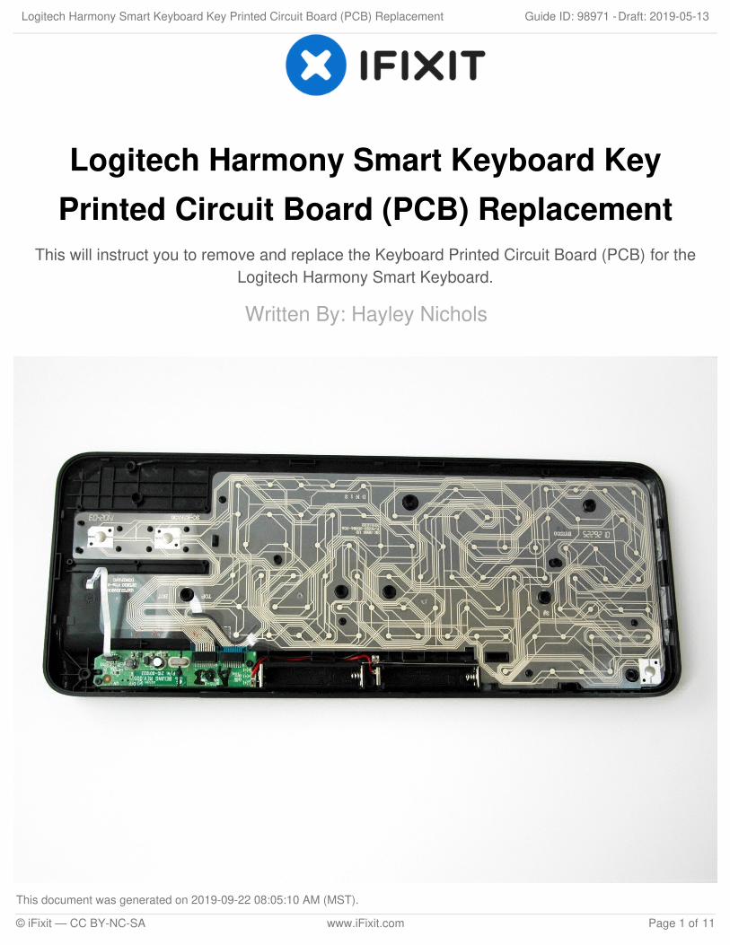
Logitech Harmony Smart Keyboard KeyPrinted Circuit Board (PCB) Replacement
This will instruct you to remove and replace the Keyboard Printed Circuit Board (PCB) for theLogitech Harmony Smart Keyboard.
Written By: Hayley Nichols
Logitech Harmony Smart Keyboard Key Printed Circuit Board (PCB) Replacement Draft: 2019-05-13Guide ID: 98971 -
This document was generated on 2019-09-22 08:05:10 AM (MST).
© iFixit — CC BY-NC-SA www.iFixit.com Page 1 of 11
INTRODUCTION
This is a replacement guide for the Logitech Harmony Smart Keyboard's key printed circuit board.
The keyboard printed circuit board (PCB) sends messages to the wifi and transmits key data to theserver.
TOOLS:Spudger (1)Phillips #1 Screwdriver (1)ESD Safe Tweezers Blunt Nose (1)
Logitech Harmony Smart Keyboard Key Printed Circuit Board (PCB) Replacement Draft: 2019-05-13Guide ID: 98971 -
This document was generated on 2019-09-22 08:05:10 AM (MST).
© iFixit — CC BY-NC-SA www.iFixit.com Page 2 of 11
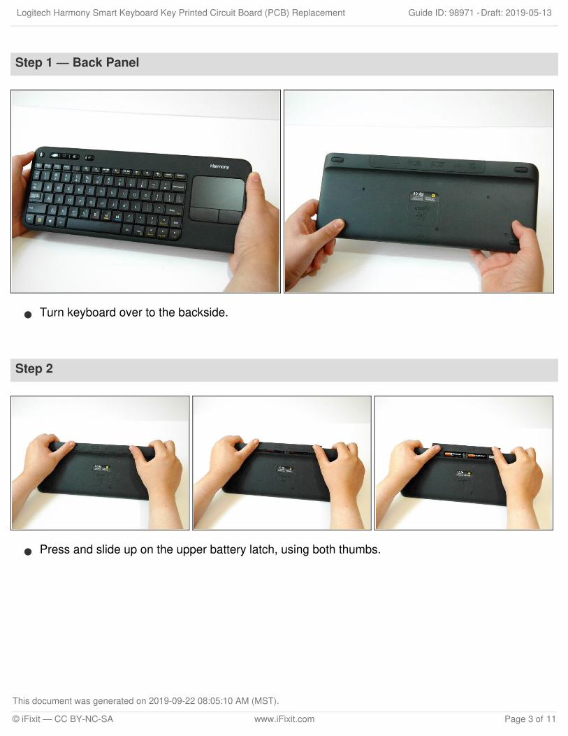
Step 1 — Back Panel
Turn keyboard over to the backside.
Step 2
Press and slide up on the upper battery latch, using both thumbs.
Logitech Harmony Smart Keyboard Key Printed Circuit Board (PCB) Replacement Draft: 2019-05-13Guide ID: 98971 -
This document was generated on 2019-09-22 08:05:10 AM (MST).
© iFixit — CC BY-NC-SA www.iFixit.com Page 3 of 11
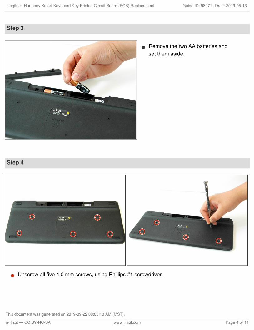
Step 3
Remove the two AA batteries andset them aside.
Step 4
Unscrew all five 4.0 mm screws, using Phillips #1 screwdriver.
Logitech Harmony Smart Keyboard Key Printed Circuit Board (PCB) Replacement Draft: 2019-05-13Guide ID: 98971 -
This document was generated on 2019-09-22 08:05:10 AM (MST).
© iFixit — CC BY-NC-SA www.iFixit.com Page 4 of 11
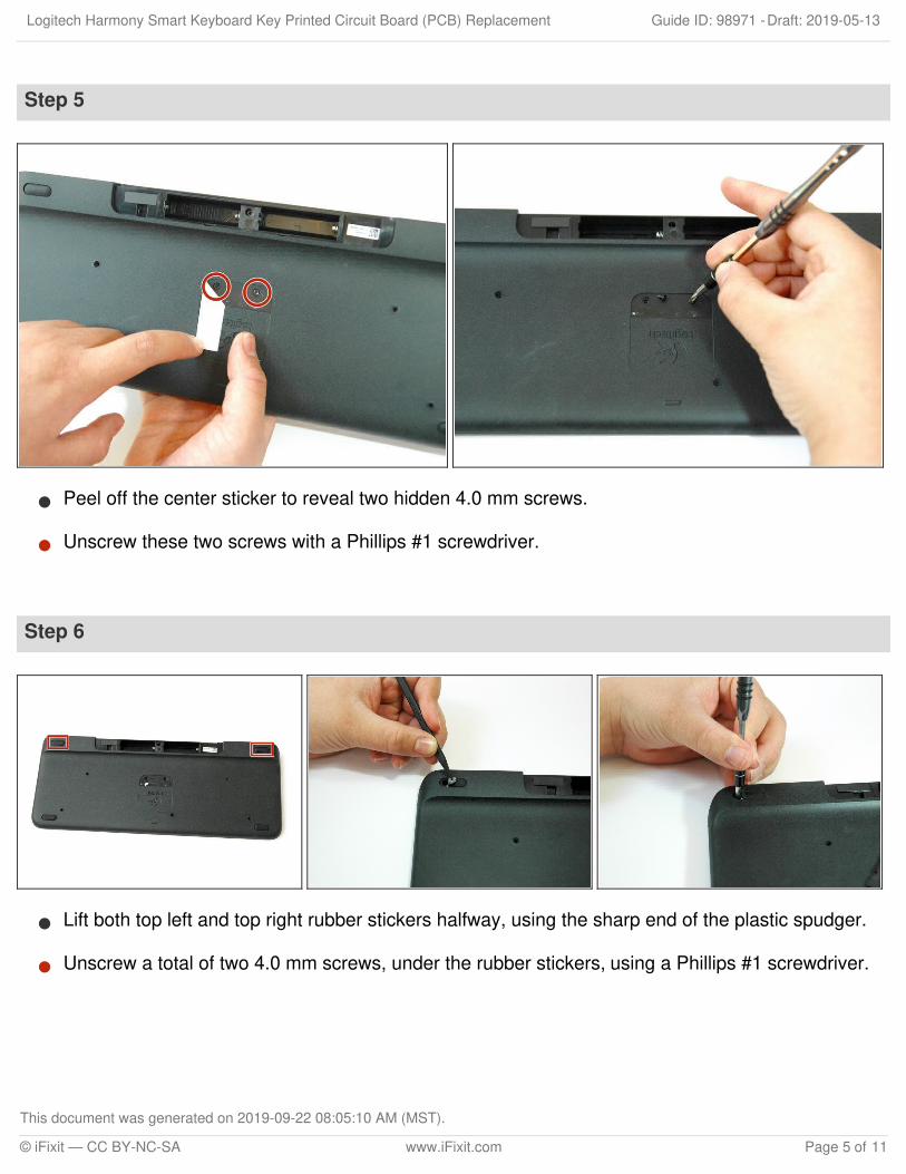
Step 5
Peel off the center sticker to reveal two hidden 4.0 mm screws.
Unscrew these two screws with a Phillips #1 screwdriver.
Step 6
Lift both top left and top right rubber stickers halfway, using the sharp end of the plastic spudger.
Unscrew a total of two 4.0 mm screws, under the rubber stickers, using a Phillips #1 screwdriver.
Logitech Harmony Smart Keyboard Key Printed Circuit Board (PCB) Replacement Draft: 2019-05-13Guide ID: 98971 -
This document was generated on 2019-09-22 08:05:10 AM (MST).
© iFixit — CC BY-NC-SA www.iFixit.com Page 5 of 11
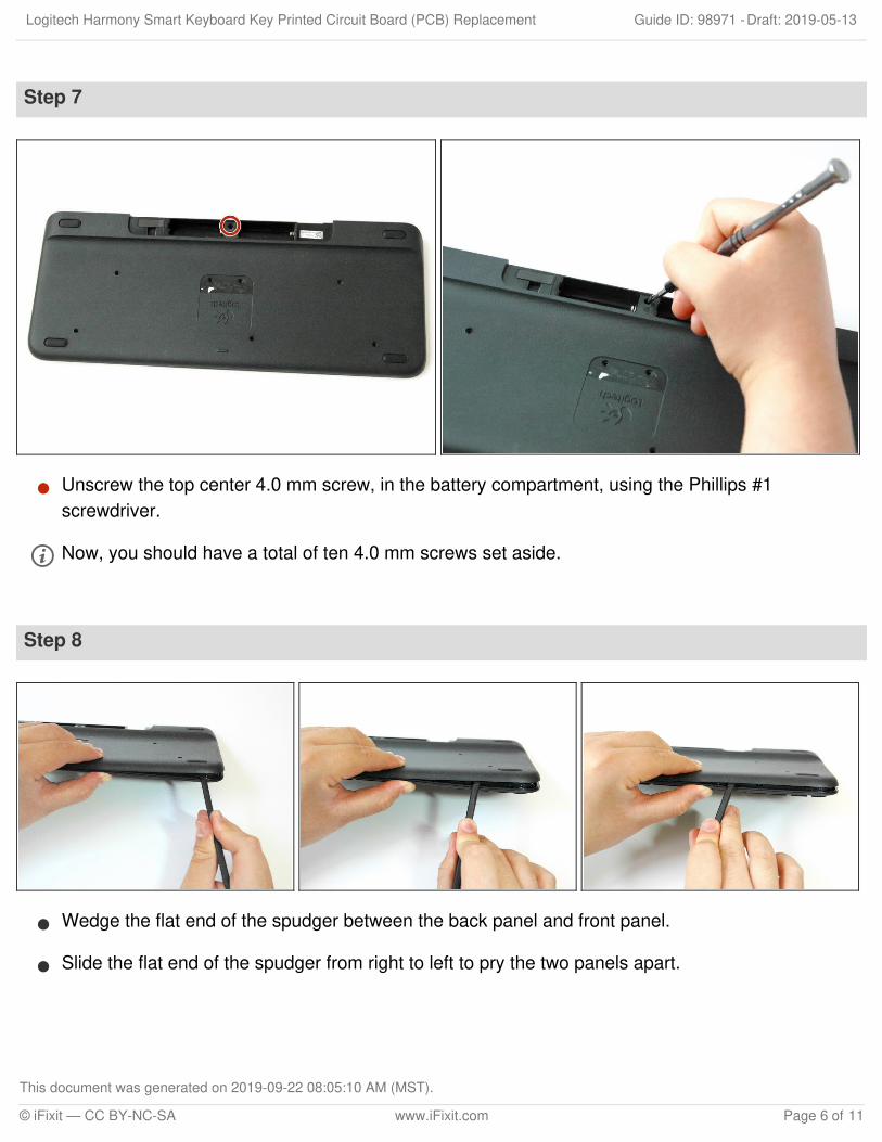
Step 7
Unscrew the top center 4.0 mm screw, in the battery compartment, using the Phillips #1screwdriver.
Now, you should have a total of ten 4.0 mm screws set aside.
Step 8
Wedge the flat end of the spudger between the back panel and front panel.
Slide the flat end of the spudger from right to left to pry the two panels apart.
Logitech Harmony Smart Keyboard Key Printed Circuit Board (PCB) Replacement Draft: 2019-05-13Guide ID: 98971 -
This document was generated on 2019-09-22 08:05:10 AM (MST).
© iFixit — CC BY-NC-SA www.iFixit.com Page 6 of 11
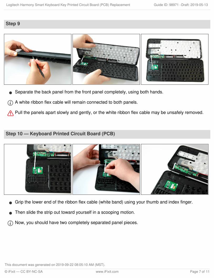
Step 9
Separate the back panel from the front panel completely, using both hands.
A white ribbon flex cable will remain connected to both panels.
Pull the panels apart slowly and gently, or the white ribbon flex cable may be unsafely removed.
Step 10 — Keyboard Printed Circuit Board (PCB)
Grip the lower end of the ribbon flex cable (white band) using your thumb and index finger.
Then slide the strip out toward yourself in a scooping motion.
Now, you should have two completely separated panel pieces.
Logitech Harmony Smart Keyboard Key Printed Circuit Board (PCB) Replacement Draft: 2019-05-13Guide ID: 98971 -
This document was generated on 2019-09-22 08:05:10 AM (MST).
© iFixit — CC BY-NC-SA www.iFixit.com Page 7 of 11
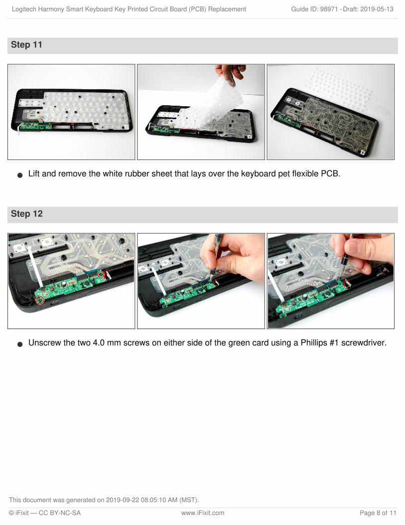
Step 11
Lift and remove the white rubber sheet that lays over the keyboard pet flexible PCB.
Step 12
Unscrew the two 4.0 mm screws on either side of the green card using a Phillips #1 screwdriver.
Logitech Harmony Smart Keyboard Key Printed Circuit Board (PCB) Replacement Draft: 2019-05-13Guide ID: 98971 -
This document was generated on 2019-09-22 08:05:10 AM (MST).
© iFixit — CC BY-NC-SA www.iFixit.com Page 8 of 11

Step 13
Lift the green card up using the flatend of the plastic spudger.
Step 14
Grip and lift the keyboard PCB upand out.
The battery wires will remainconnected.
Logitech Harmony Smart Keyboard Key Printed Circuit Board (PCB) Replacement Draft: 2019-05-13Guide ID: 98971 -
This document was generated on 2019-09-22 08:05:10 AM (MST).
© iFixit — CC BY-NC-SA www.iFixit.com Page 9 of 11
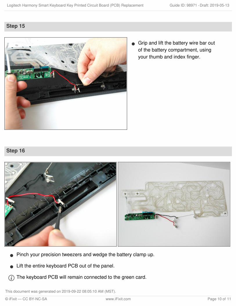
Step 15
Grip and lift the battery wire bar outof the battery compartment, usingyour thumb and index finger.
Step 16
Pinch your precision tweezers and wedge the battery clamp up.
Lift the entire keyboard PCB out of the panel.
The keyboard PCB will remain connected to the green card.
Logitech Harmony Smart Keyboard Key Printed Circuit Board (PCB) Replacement Draft: 2019-05-13Guide ID: 98971 -
This document was generated on 2019-09-22 08:05:10 AM (MST).
© iFixit — CC BY-NC-SA www.iFixit.com Page 10 of 11
To reassemble your device, follow these instructions in reverse order.
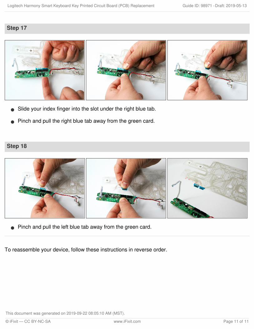
Step 17
Slide your index finger into the slot under the right blue tab.
Pinch and pull the right blue tab away from the green card.
Step 18
Pinch and pull the left blue tab away from the green card.
Logitech Harmony Smart Keyboard Key Printed Circuit Board (PCB) Replacement Draft: 2019-05-13Guide ID: 98971 -
This document was generated on 2019-09-22 08:05:10 AM (MST).
© iFixit — CC BY-NC-SA www.iFixit.com Page 11 of 11