Embed Size (px)
Citation preview

Quick Start
Logix5000 Control Systems: Connect POINT I/O Modules over an EtherNet/IP NetworkCatalog Numbers Logix5000 Controllers, 1734 POINT I/O Modules

Important User InformationSolid-state equipment has operational characteristics differing from those of electromechanical equipment. Safety Guidelines for the Application, Installation and Maintenance of Solid State Controls (publication SGI-1.1 available from your local Rockwell Automation sales office or online at http://www.rockwellautomation.com/literature/) describes some important differences between solid-state equipment and hard-wired electromechanical devices. Because of this difference, and also because of the wide variety of uses for solid-state equipment, all persons responsible for applying this equipment must satisfy themselves that each intended application of this equipment is acceptable.
In no event will Rockwell Automation, Inc. be responsible or liable for indirect or consequential damages resulting from the use or application of this equipment.
The examples and diagrams in this manual are included solely for illustrative purposes. Because of the many variables and requirements associated with any particular installation, Rockwell Automation, Inc. cannot assume responsibility or liability for actual use based on the examples and diagrams.
No patent liability is assumed by Rockwell Automation, Inc. with respect to use of information, circuits, equipment, or software described in this manual.
Reproduction of the contents of this manual, in whole or in part, without written permission of Rockwell Automation, Inc., is prohibited.
Throughout this manual, when necessary, we use notes to make you aware of safety considerations.
Allen-Bradley, CompactLogix, FLEX I/O, Logix5000, POINT I/O, Rockwell Software, Rockwell Automation, RSLogix 5000, and TechConnect are trademarks of Rockwell Automation, Inc.
Trademarks not belonging to Rockwell Automation are property of their respective companies.
WARNING: Identifies information about practices or circumstances that can cause an explosion in a hazardous environment, which may lead to personal injury or death, property damage, or economic loss.
ATTENTION: Identifies information about practices or circumstances that can lead to personal injury or death, property damage, or economic loss. Attentions help you identify a hazard, avoid a hazard, and recognize the consequence
SHOCK HAZARD: Labels may be on or inside the equipment, for example, a drive or motor, to alert people that dangerous voltage may be present.
BURN HAZARD: Labels may be on or inside the equipment, for example, a drive or motor, to alert people that surfaces may reach dangerous temperatures.
IMPORTANT Identifies information that is critical for successful application and understanding of the product.

Table of Contents
Preface About This Publication . . . . . . . . . . . . . . . . . . . . . . . . . . . . . . . . . . . . . . . . . . . . 5Before Using This Publication. . . . . . . . . . . . . . . . . . . . . . . . . . . . . . . . . . . . . . 5Other Logix5000 Control System Quick Starts . . . . . . . . . . . . . . . . . . . . . . 8POINT I/O Modules in Device-level Ring or Linear Topology . . . . . . . 8Before You Begin. . . . . . . . . . . . . . . . . . . . . . . . . . . . . . . . . . . . . . . . . . . . . . . . . . 8Where to Start . . . . . . . . . . . . . . . . . . . . . . . . . . . . . . . . . . . . . . . . . . . . . . . . . . . . 9How Hardware is Connected . . . . . . . . . . . . . . . . . . . . . . . . . . . . . . . . . . . . . 10Required Software. . . . . . . . . . . . . . . . . . . . . . . . . . . . . . . . . . . . . . . . . . . . . . . . 10Parts List . . . . . . . . . . . . . . . . . . . . . . . . . . . . . . . . . . . . . . . . . . . . . . . . . . . . . . . . 11Additional Resources . . . . . . . . . . . . . . . . . . . . . . . . . . . . . . . . . . . . . . . . . . . . . 11
Chapter 1Prepare the Distributed POINT I/O Module Hardware
Before You Begin. . . . . . . . . . . . . . . . . . . . . . . . . . . . . . . . . . . . . . . . . . . . . . . . . 13What You Need. . . . . . . . . . . . . . . . . . . . . . . . . . . . . . . . . . . . . . . . . . . . . . . . . . 14Follow These Steps . . . . . . . . . . . . . . . . . . . . . . . . . . . . . . . . . . . . . . . . . . . . . . . 15Mount and Connect the 1734-AENT Ethernet Adapter . . . . . . . . . . . . 16Mount the 1734-OB4E Digital Output Module . . . . . . . . . . . . . . . . . . . . 17Mount and Wire the 1794-PS3 Power Supply . . . . . . . . . . . . . . . . . . . . . . 18Wire the 1734-AENT Ethernet Adapter to the Power Supply . . . . . . . 19Additional Resources . . . . . . . . . . . . . . . . . . . . . . . . . . . . . . . . . . . . . . . . . . . . . 19
Chapter 2Add the POINT I/O Ethernet Adapter and Digital Output Module to an RSLogix 5000 Project
Before You Begin. . . . . . . . . . . . . . . . . . . . . . . . . . . . . . . . . . . . . . . . . . . . . . . . . 21What You Need. . . . . . . . . . . . . . . . . . . . . . . . . . . . . . . . . . . . . . . . . . . . . . . . . . 22Follow These Steps . . . . . . . . . . . . . . . . . . . . . . . . . . . . . . . . . . . . . . . . . . . . . . . 22Configure the POINT I/O Adapter and Output Module. . . . . . . . . . . . 23Add Ladder Logic to Test the 1734-OB4E Module’s Lights. . . . . . . . . . 26Download the Project to Your Logix5000 Controller . . . . . . . . . . . . . . . 29Test the 1734-OB4E Output Module’s Light . . . . . . . . . . . . . . . . . . . . . . . 30Additional Resources . . . . . . . . . . . . . . . . . . . . . . . . . . . . . . . . . . . . . . . . . . . . . 30
Index . . . . . . . . . . . . . . . . . . . . . . . . . . . . . . . . . . . . . . . . . . . . . . . . . . . . . . . . . . . . . . . . . . 31
Rockwell Automation Publication IASIMP-QS027A-EN-P - February 2012 3

Table of Contents
4 Rockwell Automation Publication IASIMP-QS027A-EN-P - February 2012

Preface
About This Publication
This quick start provides examples and procedures for including POINT I/O modules in a Logix5000 control system over an EtherNet/IP network. The programming examples are not complex, and offer easy solutions to verify that devices are functioning and communicating properly.
Before Using This Publication
You can only complete the tasks described in this publication after first completing some prerequisite tasks with a Logix5000 controller. For example, before you can add POINT I/O modules to an RSLogix 5000 project, as described in page 21, you must first create the project.
Table 1 describes the tasks you must complete before using this publication.
IMPORTANT This publication describes example tasks you complete when using POINT I/O modules on an EtherNet/IP network. The tasks described are not the only tasks you can complete with the POINT I/O modules on an EtherNet/IP network.
IMPORTANT The example graphics shown in Table 1 - Required Tasks To Complete Before Using this Quick Start on page 6 are for CompactLogix 5370 L3 controllers. Depending on the Logix5000 controller you are using, the specific steps to complete the tasks described in the table might vary.
Rockwell Automation Publication IASIMP-QS027A-EN-P - February 2012 5

Preface
For more information on how to complete the prerequisite tasks with specific Logix5000 controllers, see the Integrated Architecture: Logix5000 Control Systems Quick Starts Quick Reference, publication IASIMP-QR024.
Table 1 - Required Tasks To Complete Before Using this Quick Start
Task Description
Prepare the Logix5000 control system hardware
Assembling the control system and connecting to necessary communication networks. Some components, for example, a desired Logix5000 controller, system power supply or switch for applications operating on an EtherNet/IP network, are required. Other components, for example, a network communication module, are optional.
IMPORTANT: These graphics show the assembly of an example Logix5000 controller.
This task does not include installation of specific hardware components, for example, POINT I/O modules, used over the networks included in your application.
Prepare the computer Installing necessary software, for example, RSLogix 5000 software, on your computer.
2 (Rear)
1 (Front)
6 Rockwell Automation Publication IASIMP-QS027A-EN-P - February 2012

Preface
Configure the networks
Complete required tasks associated with the networks used in your application, such as assigning an IP address to the controller or a communication module in your Logix5000 control system.
Create an RSLogix 5000 project
Project used with your Logix5000 controller that includes all desired control system components and necessary programming, for example, adding ladder logic to test tasks associated with individual system components.
Table 1 - Required Tasks To Complete Before Using this Quick Start
Task Description
Rockwell Automation Publication IASIMP-QS027A-EN-P - February 2012 7

Preface
Other Logix5000 Control System Quick Starts
This quick start describes how to add one device on one network in a Logix5000 control system. Typically, though, a Logix5000 control system includes more than one device on one network.
For example, if a Logix5000 control system operates on an EtherNet/IP network, in addition to a controller, power supply, and communication modules, the system might use remote I/O modules, drives, or HMI terminals.
Other quick starts describe how to use different devices on different networks in Logix5000 control systems. For more information, see the Integrated Architecture: Logix5000 Control Systems Quick Starts Quick Reference, publication IASIMP-QR024.
POINT I/O Modules in Device-level Ring or Linear Topology
This publication describes how to use POINT I/O modules in an application using a EtherNet/IP network star topology configuration. It does not describe how to use the I/O modules in a device-level ring (DLR) nor linear topology via a 1734-AENTR adapter module.
For information on how to use POINT I/O modules in a DLR or linear topology, see the EtherNet/IP Embedded Switch Technology Application Guide, publication ENET-AP005.
Before You Begin
The beginning of each chapter contains the following information. You should read these sections before beginning work in each chapter:
• Before You Begin - This section lists the tasks you must complete before starting the chapter.
• What You Need - This section lists the tools that are required to complete the tasks in the chapter.
• Follow These Steps - This section illustrates the steps in the current chapter.
8 Rockwell Automation Publication IASIMP-QS027A-EN-P - February 2012

Preface
Where to Start
Prepare the Distributed POINT I/O Module Hardware
page 13
Add the POINT I/O Ethernet Adapter and Digital Output Module
to an RSLogix 5000 Project
page 21
Prerequisite TasksDescribed in Before Using This Publication on page 5.
1. Prepare the Logix5000 control system hardware.2. Prepare the computer.3. Configure the networks.4. Create an RSLogix 5000 project.
Logix5000 Controller
Rockwell Automation Publication IASIMP-QS027A-EN-P - February 2012 9

Preface
How Hardware is Connected
This quick start demonstrates the following possible control system.
Required Software
To complete examples in this quick start, you need the software described in this table.
Software Version Required for This Task
RSLogix 5000 20.00.00 or later(1)
(1) RSLogix 5000 software, version 20.00.00 or later is required for use of this quick start because the example Logix5000 controller, and associated tasks, described herein are completed in a CompactLogix 5370 L3 control system. CompactLogix 5370 control systems require RSLogix 5000 software, version 20.00.00 or later. If you connect a 1734 POINT I/O module over an EtherNet/IP network in a Logix5000 control system that uses a different controller, the minimum version may differ.
Create or change RSLogix 5000 projects to use POINT I/O modules.
BOOTP/DHCP utility Version automatically installed with RSLogix 5000 software and varies according to that software’s version.
Set or change the IP address for 1734-AENT POINT I/O Ethernet adapter.
12
34
56
78
0 20 1734-AENTR
ModuleStatus
NetworkActivity
NetworkStatus
Point BusStatus
SystemPower
FieldPower
POINT I O
Link 1 Activity/Status
Link 2 Activity/Status
IP A
DD
RE
SS
Computer
POINT I/O Modules
Logix5000 Controller with Ethernet
Connection
Stratix 6000 Managed Switch
10 Rockwell Automation Publication IASIMP-QS027A-EN-P - February 2012

Preface
Parts List
To complete the tasks described in this publication, you need the parts listed in this table.
For a list of parts required to complete the prerequisite tasks listed in Table 1 - Required Tasks To Complete Before Using this Quick Start on page 6, see the documentation describing those tasks.
Additional Resources
Use the additional resources listed in this table for more information when using POINT I/O modules over an EtherNet/IP network in a Logix5000 controller project.
Quantity Cat. No. Description
1 1734-AENT POINT I/O Ethernet adapter
1 1734-OB4E POINT I/O protected output module
1 1734-TB or 1734-TBS Wiring base with removable IEC screw terminals (1734-TB)
Wiring base with removable IEC spring terminals (1734-TBS)
1 1794-PS3 FLEX I/O 85…264V AC to 24V DC 3 A power supply
1 1585J-M8PBJM-2 RJ45-to-RJ45 patchcord Ethernet cables
Table 2 - Additional Resources
Resource Description
POINT I/O Ethernet Adapter Installation Instructions, publication 1734-IN590
Describes how to install the 1734-AENT POINT I/O Ethernet adapter and contains technical specifications.
POINT I/O and ArmorPOINT I/O 2 Port EtherNet/IP Adapters User Manual, publication 1734-UM014
Describes how to install, configure, and troubleshoot your 1734-AENT POINT I/O EtherNet/IP adapter.
POINT I/O Protected Output Module, publication 1734-IN056
Describes how to install the 1734-OB4E module.
POINT I/O Wiring Base Assembly Installation Instructions, publication 1734-IN013
Describes how to install the POINT I/O wiring base.
Rockwell Automation Publication IASIMP-QS027A-EN-P - February 2012 11

Preface
You can view or download publications at http://www.rockwellautomation.com/literature/. To order paper copies of technical documentation, contact your local Allen-Bradley distributor or Rockwell Automation sales representative.
FLEX I/O DC Power Supply Installation Instructions, publication 1794-IN069
Describes how to install the 1794-PS and 1794-PS13 power supplies.
Logix5000 Controllers Common Procedures Programming Manual, publication 1756-PM001
Provides details about adding and configuring modules, establishing communication, and writing ladder logic.
Industrial Automation Wiring and Grounding Guidelines, publication 1770-4.1
Provides general guidelines for installing a Rockwell Automation industrial system.
Product Certifications website, http://www.ab.com Provides declarations of conformity, certificates, and other certification details.
Table 2 - Additional Resources
Resource Description
12 Rockwell Automation Publication IASIMP-QS027A-EN-P - February 2012

Chapter 1
Prepare the Distributed POINT I/O Module Hardware
In this chapter, you learn how to complete the following tasks:• Install the 1734-AENT Ethernet adapter• Install the 1734-OB4E digital output module• Install a 1794-PS3 FLEX I/O power supply• Connect power to the 1734-AENT Ethernet adapter
Before You Begin
You must complete these tasks before using this chapter:• The tasks described in Before Using This Publication on page 5, including:
– Prepare the Logix5000 control system hardware– Prepare the computer– Configure the networks - The tasks described in this chapter require an
EtherNet/IP network.– Create an RSLogix 5000 project
The example RSLogix 5000 project used in this chapter uses a CompactLogix 5370 L3 controller.
Rockwell Automation Publication IASIMP-QS027A-EN-P - February 2012 13

Chapter 1 Prepare the Distributed POINT I/O Module Hardware
What You Need
The following table lists the products that you need to complete the tasks described in this chapter.
Quantity Cat. No. Description
1 1734-AENT POINT I/O Ethernet adapter
1 1734-OB4E POINT I/O protected output module
1 1734-TB or 1734-TBS Wiring base with removable IEC screw terminals (1734-TB)
Wiring base with removable IEC spring terminals (1734-TBS)
1 1794-PS3 FLEX I/O 85…264V AC to 24V DC 3 A power supply
14 Rockwell Automation Publication IASIMP-QS027A-EN-P - February 2012

Prepare the Distributed POINT I/O Module Hardware Chapter 1
Follow These Steps
Mount and Connect the 1734-AENT Ethernet
Adapter
Mount the 1734-OB4E Digital Output Module
Mount and Wire the 1794-PS3 Power Supply
Wire the 1734-AENT Ethernet Adapter to the
Power Supply
page 16
page 19
page 18
page 17
12
34
56
78
ModuleStatus
Network ActivityStatus
NetworkStatus
1734-AENT
PointBusStatus
FieldPower
SystemPower
0 20
24VDCSourceOutput
1734OB4E
Rockwell Automation Publication IASIMP-QS027A-EN-P - February 2012 15

Chapter 1 Prepare the Distributed POINT I/O Module Hardware
Mount and Connect the 1734-AENT Ethernet Adapter
1. Position the adapter vertically in front of the DIN rail and press firmly onto the DIN rail until the adapter locks into place.
2. To set the module’s IP address to a valid number, set the module’s thumbwheel switches to a number between 001 and 254.
Numbers outside that range are invalid. If the switches are set to a valid number at powerup, the module automatically uses that number for its IP address.
3. Plug a 1585J-M4TBJM-1, Ethernet cable (straight-through) into a port on the Stratix 6000 switch.
4. Plug the other end of the Ethernet cable into the Ethernet port on the 1734-AENT POINT I/O Ethernet adapter.
5. Remove the safety end cap.
IMPORTANT In addition to the thumbwheel switches, there are other methods to assign an IP address to the POINT I/O adapter, such as using the BOOTP/DHCP utility. For more information on how to set the IP address, see POINT I/O Ethernet Adapter Installation Instructions, publication 1734-IN590.
ModuleStatus
Network ActivityStatus
NetworkStatus
1734-AENT
PointBusStatus
Field
SystemPower
0 20Thumbwheel Switches
12
34
56
78
16 Rockwell Automation Publication IASIMP-QS027A-EN-P - February 2012

Prepare the Distributed POINT I/O Module Hardware Chapter 1
Mount the 1734-OB4E Digital Output Module
1. Install the removable terminal base (RTB) on the mounting base.
Make sure the handle is in the down position.
2. Using a small screwdriver, rotate the keyswitch on the mounting base to match the position on the keyswitch on the I/O module.
This example shows the keyswitch in position 1.
3. Press the 1734-OB4E module into the wiring base.
4. Snap the handle up to lock the RTB on the module.
5. Connect the wiring base assembly, including mounting base, module, and RTB, to the POINT I/O Ethernet adapter via the slots on the right side of the adapter.
6. Slide the wiring base assembly along the right side of the network adapter and press it onto the DIN rail.
Mounting Base
Handle
Removable Terminal Block
Tongue-and-groove Slots
Module
Rockwell Automation Publication IASIMP-QS027A-EN-P - February 2012 17

Chapter 1 Prepare the Distributed POINT I/O Module Hardware
Mount and Wire the 1794-PS3 Power Supply
Use a 1794 FLEX I/O power supply to power the distributed POINT I/O modules. This publication uses the 1794-PS3 power supply.
1794-PS3 Power Supply
1. Hook the upper-lip of the DIN rail latch onto the DIN rail.
2. Press the module onto the DIN rail next to the POINT I/O Ethernet adapter.
3. Connect the 120/240V AC power L1, L2/N and Ground wires to your AC power source.
WARNING: Verify that all incoming power is turned off before wiring power.
rewoPCD V42YLPPUS REWOP3SP-4971
V42
MOC
GRL2/NL1
18 Rockwell Automation Publication IASIMP-QS027A-EN-P - February 2012

Prepare the Distributed POINT I/O Module Hardware Chapter 1
Wire the 1734-AENT Ethernet Adapter to the Power Supply
1. Connect the 12/24V DC common and 12/24V DC power wires from the power supply to the adapter.
2. Turn on incoming power.
Additional Resources
For a list of additional resources that might assist you when preparing the distributed POINT I/O module hardware, see page 5.
ModuleStatus
Network ActivityStatus
NetworkStatus
1734-AENT
PointBusStatus
FieldPower
SystemPower
0 20
24VDCSourceOutput
1734OB4E
Common
Power
Rockwell Automation Publication IASIMP-QS027A-EN-P - February 2012 19

Chapter 1 Prepare the Distributed POINT I/O Module Hardware
Notes:
20 Rockwell Automation Publication IASIMP-QS027A-EN-P - February 2012

Chapter 2
Add the POINT I/O Ethernet Adapter and Digital Output Module to an RSLogix 5000 Project
In this chapter, you complete the following tasks:• Add the 1734-AENT Ethernet adapter to the RSLogix 5000 project• Add the 1734-OB4E digital output module to the RSLogix 5000 project• Use ladder logic to test the 1734-OB4E digital output module’s lights
Before You Begin
You must complete these tasks before using this chapter:• The tasks described in Before Using This Publication on page 5, including:
– Prepare the Logix5000 control system hardware– Prepare the computer– Configure the networks– Create an RSLogix 5000 project
The example RSLogix 5000 project used in this chapter uses a CompactLogix 5370 L3 controller.
• These tasks described in Chapter 1, Prepare the Distributed POINT I/O Module Hardware on page 13:– Mount and Connect the 1734-AENT Ethernet Adapter– Mount the 1734-OB4E Digital Output Module– Mount and Wire the 1794-PS3 Power Supply– Wire the 1734-AENT Ethernet Adapter to the Power Supply
• Verify that the 1734-AENT POINT I/O Ethernet adapter’s thumbwheel switches are set to a valid IP address, as described on page 16.
Rockwell Automation Publication IASIMP-QS027A-EN-P - February 2012 21
Chapter 2 Add the POINT I/O Ethernet Adapter and Digital Output Module to an RSLogix 5000 Project
What You Need
You need RSLogix 5000 software to complete the tasks in this chapter.
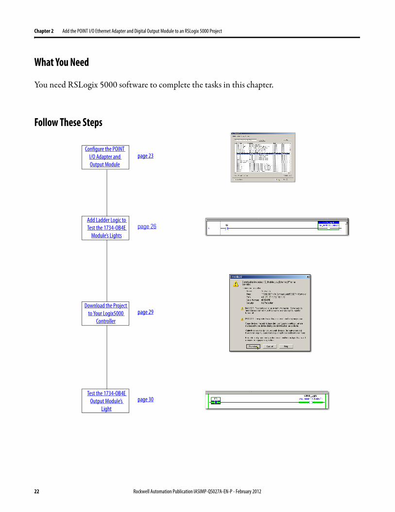
Follow These Steps
Configure the POINT I/O Adapter and Output Module
page 23
Add Ladder Logic to Test the 1734-OB4E
Module’s Lightspage 26
Download the Project to Your Logix5000
Controllerpage 29
Test the 1734-OB4E Output Module’s
Light
page 30
22 Rockwell Automation Publication IASIMP-QS027A-EN-P - February 2012

Add the POINT I/O Ethernet Adapter and Digital Output Module to an RSLogix 5000 Project Chapter 2
Configure the POINT I/O Adapter and Output Module
1. Open your RSLogix 5000 project and verify that it is Offline with the controller.
2. Right-click Ethernet in the I/O Configuration folder and choose New Module.
3. Select the 1734-AENT Ethernet adapter and click Create.
4. Type the name for the adapter.
5. Type the adapter’s IP address.
6. Click Change.
Rockwell Automation Publication IASIMP-QS027A-EN-P - February 2012 23

Chapter 2 Add the POINT I/O Ethernet Adapter and Digital Output Module to an RSLogix 5000 Project
7. Make these changes on the Module Definition dialog box.
a. Select the Series.b. Select the Revision.c. Select the Chassis Size.
Chassis size equals the number of POINT I/O modules + 1 for the adapter.
In this example, the Chassis Size is 2 to account for the 1734-AENT Ethernet adapter and the 1734-OB4E digital output module.
d. Select Disable Keying.e. Click OK.
RSLogix 5000 software warns you about the effect of module definition changes.
f. Click OK.
8. When the New Module dialog box reappears, click OK.
The adapter is added to the I/O configuration.
24 Rockwell Automation Publication IASIMP-QS027A-EN-P - February 2012

Add the POINT I/O Ethernet Adapter and Digital Output Module to an RSLogix 5000 Project Chapter 2
9. Right-click the 1734-AENT Ethernet adapter and choose New Module.
10. Select the 1734-OB4E digital output module and click Create.
11. Configure the following parameters:
• Name• Slot (Slot number is the
position of the module to the right of the adapter.)
• Electronic Keying
12. Click OK.
The 1734-OB4E digital output module is added to theI/O configuration.
13. Save the project.
Rockwell Automation Publication IASIMP-QS027A-EN-P - February 2012 25

Chapter 2 Add the POINT I/O Ethernet Adapter and Digital Output Module to an RSLogix 5000 Project
Add Ladder Logic to Test the 1734-OB4E Module’s Lights
1. In RSLogix 5000 software’s controller organizer, expand Tasks >MainTask>MainProgram.
2. Double-click MainRoutine.
A blank routine opens.
3. Add a new rung to the routine.
4. From the Element Toolbar, drag and drop an Examine On element and an Output Energize element onto the rung.
5. Double-click the ? in the Examine On element.
6. Type PB for push button.
7. Press Enter.
26 Rockwell Automation Publication IASIMP-QS027A-EN-P - February 2012

Add the POINT I/O Ethernet Adapter and Digital Output Module to an RSLogix 5000 Project Chapter 2
8. Right-click PB and choose New “PB”.
9. When the New Tag dialog box appears, click Create and Close to use the default values.
10. Double-click the ? in the Output Energize element.
11. Name the Output Energize element OB4E_Light.
IMPORTANT Do not use spaces in the tag name. Use underscores (__) instead.
Rockwell Automation Publication IASIMP-QS027A-EN-P - February 2012 27

Chapter 2 Add the POINT I/O Ethernet Adapter and Digital Output Module to an RSLogix 5000 Project
12. Right-click the OB4E_Light tag and choose New “OB4E_Light”.
OB4E_Light is an alias tag for the I/O point tag name. With an alias tag, you can assign a simple name to a physical I/O point address.
13. From the Type pull-down menu, choose Alias.
14. From the Alias For pull-down menu, browse to the 1734-OB4E digital output module and choose any bit.
This example uses my_aent:1:O.Data[0].
15. Click Create and Close.
This graphic shows the rung created with these steps.
28 Rockwell Automation Publication IASIMP-QS027A-EN-P - February 2012

Add the POINT I/O Ethernet Adapter and Digital Output Module to an RSLogix 5000 Project Chapter 2
Download the Project to Your Logix5000 Controller
1. Save your changes.
2. Move the controller’s switch to Program.
3. Click the Controller Status icon and choose Download.
4. Click Download.
RUN
REM
PROG
Rockwell Automation Publication IASIMP-QS027A-EN-P - February 2012 29

Chapter 2 Add the POINT I/O Ethernet Adapter and Digital Output Module to an RSLogix 5000 Project
Test the 1734-OB4E Output Module’s Light
1. Move the controller’s mode switch to the RUN position.
2. If not open, open the project’s Main Routine to find the ladder logic written earlier in this chapter.
3. Select the PB and press Ctrl+T.
This toggles the state from 0 to 1 (off to on).
4. Verify that the light on the distributed digital output module turns on.
5. Press Ctrl+T to toggle the state back to 0 (off ).
6. Choose Go Offline.
Additional Resources
For a list of additional resources that might assist you when preparing the PowerFlex 40 drive hardware, see page 11.
30 Rockwell Automation Publication IASIMP-QS027A-EN-P - February 2012

Index
BBOOTP/DHCP utility 10
Cconnections
hardware 10conventions 11
DDLR topology 8
EEthernet adapter
assign IP address 16, 23connect 16
Hhardware
connect Ethernet adapter 16connect I/O modules 17connect power supply 18install removable terminal base 17preparation 13-19removable terminal base keyswitch 17
II/O modules
add to RSLogix 5000 project 21-25connect 17test light 30
IP addressassign to Ethernet adapter 16, 23
Kkeyswitch
on removable terminal base 17
Lladder logic
alias for tag 28elements 26routine 26use to test I/O module’s lights 26-28
linear topology 8Logix5000 controllers
prerequisite tasks 5-7quick starts 8
Nnetwork topologies
DLR 8linear 8
Pparts
required to complete tasks 11power supply
connect 18prerequisite tasks 5-7
Qquick starts
for devices in Logix5000 control systems 8
Rremovable terminal base
install 17removable terminal base keyswitch 17requirements
hardware preparation 13-19parts 11prerequisite tasks 5-7software 10
RSLogix 5000 softwareadd element to routine 26add I/O modules to project 21-25add routine to project 26alias for tag 28ladder logic 26-28requirements 10test I/O module’s light 30
Ssoftware
BOOTP/DHCP utility 10RSLogix 5000 10
Ttasks
prerequisite tasks 5-7
Rockwell Automation Publication IASIMP-QS027A-EN-P - February 2012 31

Index
Notes:
32 Rockwell Automation Publication IASIMP-QS027A-EN-P - February 2012


Rockwell Otomasyon Ticaret A.Ş., Kar Plaza İş Merkezi E Blok Kat:6 34752 İçerenköy, İstanbul, Tel: +90 (216) 5698400
Publication IASIMP-QS027A-EN-P - February 2012Copyright © 2012 Rockwell Automation, Inc. All rights reserved. Printed in the U.S.A.
Rockwell Automation Support
Rockwell Automation provides technical information on the Web to assist you in using its products. At http://www.rockwellautomation.com/support/, you can find technical manuals, a knowledge base of FAQs, technical and application notes, sample code and links to software service packs, and a MySupport feature that you can customize to make the best use of these tools.
For an additional level of technical phone support for installation, configuration, and troubleshooting, we offer TechConnect support programs. For more information, contact your local distributor or Rockwell Automation representative, or visit http://www.rockwellautomation.com/support/.
Installation Assistance
If you experience a problem within the first 24 hours of installation, review the information that is contained in this manual. You can contact Customer Support for initial help in getting your product up and running.
New Product Satisfaction Return
Rockwell Automation tests all of its products to ensure that they are fully operational when shipped from the manufacturing facility. However, if your product is not functioning and needs to be returned, follow these procedures.
Documentation Feedback
Your comments will help us serve your documentation needs better. If you have any suggestions on how to improve this document, complete this form, publication RA-DU002, available at http://www.rockwellautomation.com/literature/.
United States or Canada 1.440.646.3434
Outside United States or Canada Use the Worldwide Locator at http://www.rockwellautomation.com/support/americas/phone_en.html, or contact your local Rockwell Automation representative.
United States Contact your distributor. You must provide a Customer Support case number (call the phone number above to obtain one) to your distributor to complete the return process.
Outside United States Please contact your local Rockwell Automation representative for the return procedure.
Power, Control and Information Solutions HeadquartersAmericas: Rockwell Automation, 1201 South Second Street, Milwaukee, WI 53204-2496 USA, Tel: (1) 414.382.2000, Fax: (1) 414.382.4444Europe/Middle East/Africa: Rockwell Automation NV, Pegasus Park, De Kleetlaan 12a, 1831 Diegem, Belgium, Tel: (32) 2 663 0600, Fax: (32) 2 663 0640Asia Pacific: Rockwell Automation, Level 14, Core F, Cyberport 3, 100 Cyberport Road, Hong Kong, Tel: (852) 2887 4788, Fax: (852) 2508 1846
www.rockwel lautomation.com