Embed Size (px)
Citation preview

Programming Manual
Logix5000 Controllers IEC 61131-3 Compliance 1756 ControlLogix, 1769 CompactLogix, 1769 Compact GuardLogix, 1789 SoftLogix, 5069 CompactLogix, Studio 5000 Logix Emulate

Important user information
Read this document and the documents listed in the additional resources section about installation, configuration, and operation of this equipment before you install, configure, operate, or maintain this product. Users are required to familiarize themselves with installation and wiring instructions in addition to requirements of all applicable codes, laws, and standards.
Activities including installation, adjustments, putting into service, use, assembly, disassembly, and maintenance are required to be carried out by suitably trained personnel in accordance with applicable code of practice. If this equipment is used in a manner not specified by the manufacturer, the protection provided by the equipment may be impaired.
In no event will Rockwell Automation, Inc. be responsible or liable for indirect or consequential damages resulting from the use or application of this equipment.
The examples and diagrams in this manual are included solely for illustrative purposes. Because of the many variables and requirements associated with any particular installation, Rockwell Automation, Inc. cannot assume responsibility or liability for actual use based on the examples and diagrams.
No patent liability is assumed by Rockwell Automation, Inc. with respect to use of information, circuits, equipment, or software described in this manual.
Reproduction of the contents of this manual, in whole or in part, without written permission of Rockwell Automation, Inc., is prohibited.
Throughout this manual, when necessary, we use notes to make you aware of safety considerations.
WARNING: Identifies information about practices or circumstances that can cause an explosion in a hazardous environment, which may lead to personal injury or death, property damage, or economic loss.
ATTENTION: Identifies information about practices or circumstances that can lead to personal injury or death, property damage, or economic loss. Attentions help you identify a hazard, avoid a hazard, and recognize the consequence
Important: Identifies information that is critical for successful application and understanding of the product.
Labels may also be on or inside the equipment to provide specific precautions.
SHOCK HAZARD: Labels may be on or inside the equipment, for example, a drive or motor, to alert people that dangerous voltage may be present.
BURN HAZARD: Labels may be on or inside the equipment, for example, a drive or motor, to alert people that surfaces may reach dangerous temperatures.
ARC FLASH HAZARD: Labels may be on or inside the equipment, for example, a motor control center, to alert people to potential Arc Flash. Arc Flash will cause severe injury or death. Wear proper Personal Protective Equipment (PPE). Follow ALL Regulatory requirements for safe work practices and for Personal Protective Equipment (PPE).
Allen-Bradley, Rockwell Software, Rockwell Automation, and TechConnect are trademarks of Rockwell Automation, Inc.
Trademarks not belonging to Rockwell Automation are property of their respective companies.

Rockwell Automation Publication 1756-PM018E-EN-P - December 2016 3
This manual contains new and updated information. The following table contains the changes made to this revision.
Change Topic
Updated IEC Compliance tables IEC Compliance Tables on page 14
Summary of changes


Rockwell Automation Publication 1756-PM018E-EN-P - December 2016 5
Table of contents
Studio 5000 environment.................................................................................................... 8 Additional resources ............................................................................................................. 8 Legal notices ........................................................................................................................... 9
Chapter 1
Introduction ........................................................................................................................ 11 Operating System ............................................................................................................... 12 Data Definitions ................................................................................................................. 12 Programming Languages ................................................................................................... 12 Instruction Set .................................................................................................................... 13 IEC61131-3 Program Portability ................................................................................... 13 IEC Compliance Tables ................................................................................................... 14
Preface
IEC61131-3 Compliance
Index


Rockwell Automation Publication 1756-PM018E-EN-P - December 2016 7
Preface
This manual explains the series of specifications developed by the International Electrotechnical Commission (IEC) for programmable controllers and how to use them with your Logix5000™ controller and programming application.
This manual is one of a set of related manuals that show common procedures for programming and operating Logix5000 controllers. For a complete list of common procedures manuals, see the Logix 5000 Controllers Common Procedures Programming Manual, publication 1756-PM001.
The term Logix5000 controller refers to any controller that is based on the Logix5000 operating system, such as:
• CompactLogix controllers
• ControlLogix controllers
• DriveLogix controllers
• FlexLogix controllers
• SoftLogix5800 controllers
• Studio 5000 Logix Emulate
Preface
8 Rockwell Automation Publication 1756-PM018E-EN-P - December 2016
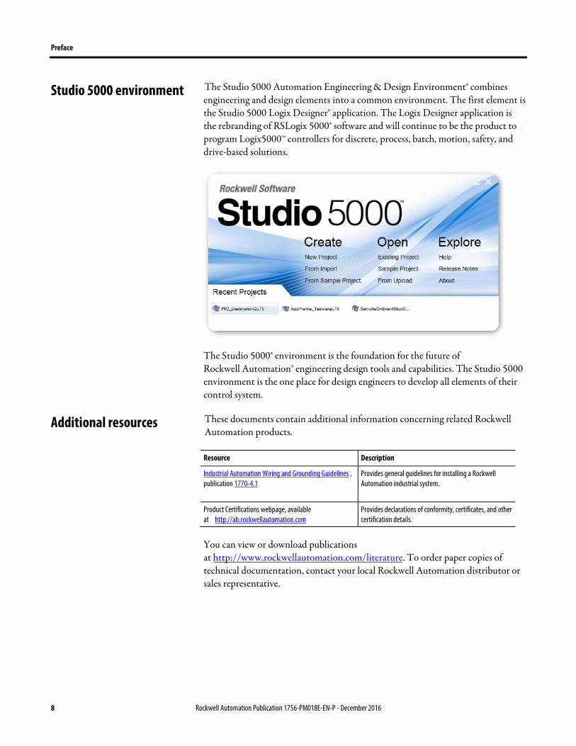
The Studio 5000 Automation Engineering & Design Environment® combines engineering and design elements into a common environment. The first element is the Studio 5000 Logix Designer® application. The Logix Designer application is the rebranding of RSLogix 5000® software and will continue to be the product to program Logix5000™ controllers for discrete, process, batch, motion, safety, and drive-based solutions.
The Studio 5000® environment is the foundation for the future of Rockwell Automation® engineering design tools and capabilities. The Studio 5000 environment is the one place for design engineers to develop all elements of their control system.
These documents contain additional information concerning related Rockwell Automation products.
Resource Description
Industrial Automation Wiring and Grounding Guidelines , publication 1770-4.1
Provides general guidelines for installing a Rockwell Automation industrial system.
Product Certifications webpage, available at http://ab.rockwellautomation.com
Provides declarations of conformity, certificates, and other certification details.
You can view or download publications at http://www.rockwellautomation.com/literature. To order paper copies of technical documentation, contact your local Rockwell Automation distributor or sales representative.
Studio 5000 environment
Additional resources

Preface
Rockwell Automation Publication 1756-PM018E-EN-P - December 2016 9
Copyright Notice
© 2016 Rockwell Automation, Inc. All rights reserved. Printed in USA.
This document and any accompanying Rockwell Software products are copyrighted by Rockwell Automation, Inc. Any reproduction and/or distribution without prior written consent from Rockwell Automation, Inc. is strictly prohibited. Please refer to the license agreement for details.
End User License Agreement (EULA)
You can view the Rockwell Automation End-User License Agreement ("EULA") by opening the License.rtf file located in your product's install folder on your hard drive.
Trademark Notices
Allen-Bradley, Rockwell Automation, Rockwell Software, CompactLogix, ControlLogix, DriveLogix, FactoryTalk, FactoryTalk Administration Console, FactoryTalk AssetCentre, FactoryTalk Batch, FactoryTalk Directory, FactoryTalk Integrator, FactoryTalk Security, FactoryTalk Services Platform, FactoryTalk View Machine Edition, FactoryTalk View SE, Logix5000, Logix Designer, RSLinx Classic, Rockwell Software Security Emulator, RSLogix 5000, and Studio 5000 are trademarks of Rockwell Automation, Inc.
Any Rockwell Automation software or hardware not mentioned here is also a trademark, registered or otherwise, of Rockwell Automation, Inc.
Other Trademarks
CmFAS Assistant, CmDongle, CmStick, CodeMeter, CodeMeter Control Center, and WIBU are trademarks of WIBU-SYSTEMS AG in the United States and/or other countries.
All other trademarks are the property of their respective holders and are hereby acknowledged.
Warranty
This product is warranted in accordance with the product license. The product’s performance may be affected by system configuration, the application being performed, operator control, maintenance, and other related factors. Rockwell Automation is not responsible for these intervening factors. The instructions in this document do not cover all the details or variations in the equipment, procedure, or process described, nor do they provide directions for meeting every possible contingency during installation, operation, or maintenance. This product’s implementation may vary among users.
Legal notices

Preface
10 Rockwell Automation Publication 1756-PM018E-EN-P - December 2016
This document is current as of the time of release of the product; however, the accompanying software may have changed since the release. Rockwell Automation, Inc. reserves the right to change any information contained in this document or the software at any time without prior notice. It is your responsibility to obtain the most current information available from Rockwell when installing or using this product.
Environmental compliance
Rockwell Automation maintains current product environmental information on its website at http://www.rockwellautomation.com/rockwellautomation/about-us/sustainability-ethics/product-environmental-compliance.page
Contact Rockwell
Customer Support Telephone — 1.440.646.3434
Online Support — http://www.rockwellautomation.com/support/
Rockwell Automation Publication 1756-PM018E-EN-P - December 2016 11
Chapter 1
IEC61131-3 Compliance
This manual is compliant with the International Electrotechnical Commission specification (IEC61131) Third Edition.
The IEC has developed a series of specifications for programmable controllers. These specifications are intended to promote international unification of equipment and programming languages for use in the controls industry. These standards provide the foundation for Logix5000 controllers and the Logix Designer application.
The IEC programmable controller specification (IEC61131) breaks down into five parts, each focusing on another aspect of the control system.
• Part 1: General Information
• Part 2: Equipment and Requirements Test
• Part 3: Programming Languages
• Part 4: User Guidelines
• Part 5: Messaging Service Specification
The controls industry as a whole has focused on part 3 (IEC61131-3), Programming Languages, because it provides the cornerstone for implementing the other standards and provides the most significant end user benefit by reducing training cost. Because of this, only IEC61131-3 is addressed here.
The IEC61131-3 programming language specification addresses numerous aspects of programmable controllers, including the operating system execution, data definitions, programming languages, and instruction set. Components of the IEC61131-3 specification are categorized by the specification as required, optional, or extensions. By so doing, the IEC61131-3 specification provides a minimum set of functionality that can be extended to meet end user application needs. The downside to this approach is that each programmable control system vendor may implement different components of the specification or provide different extensions.
Introduction

Chapter 1 IEC61131-3 Compliance
12 Rockwell Automation Publication 1756-PM018E-EN-P - December 2016
The multitasking operating system (OS) of Logix5000 controllers complies with the IEC61131-3 definition. In IEC61131-3, the programmable controller OS can contain zero or more tasks, that can execute one or more programs each containing one or more functions or routines. According to IEC61131-3, the number of each of these components is implementation dependent. Logix5000 controllers provide multiple tasks, each containing multiple programs and an unlimited number of functions or routines.
IEC61131-3 provides an option for creating task execution classifications. Tasks may be configured as continuous, periodic, or event based. Logix5000 controllers support both continuous and periodic tasks. A continuous task does not need to be scheduled, because it uses any left over processing time when other tasks are dormant. Periodic tasks are scheduled to operate based on a reoccurring time period, configurable starting as low as 1 millisecond (ms). The IEC61131-3 specification does not specify a time base for periodic task configuration. An IEC61131-3 event based task triggers upon detection of the rising edge of a configured input.
The IEC61131-3 specification provides access to memory through the creation of named variables, consisting of a minimum of six characters (Logix Designer application supports a minimum of 1 character) starting with an underscore "_" or an alpha character (A-Z), followed by one or more characters consisting of an underscore "_", alpha character (A-Z) or a number (0-9). Optionally, lower case alpha characters (a-z) can be supported as long as they are case insensitive (A = a, B = b, C = c …). Logix5000 controllers provide full compliance with this definition, support the lower case option, and extend the name to support up to 40 characters.
Data variables in IEC61131-3 may be defined so that they are accessible to all programs within a resource or controller, or limited access is provided only to the functions or routines within a single program. To pass data between multiple resources or controllers, access paths may be configured to define the location of the data within a system. Logix5000 controllers provide compliance by providing program scoped or controller scoped data and permitting the configuration of access paths using produced/consumed data.
The memory interpretation of a variable within IEC61131-3 is defined through the use of an elementary data type or an optional derived data type created from a group of multiple data types. Logix5000 controllers support the use of the BOOL (1 bit), SINT (8 bit integer), INT (16 bit integer), DINT (32 bit integer), LINT (64 bit integer) and REAL (IEEE floating point number) elementary data types. Additionally, the optional derived data types are supported through the creation of user defined structures and arrays.
The IEC61131-3 specification defines five programming languages and a set of common elements. All languages are defined as optional, but at least one must be
Operating System
Data Definitions
Programming Languages

IEC61131-3 Compliance Chapter 1
Rockwell Automation Publication 1756-PM018E-EN-P - December 2016 13
supported to claim compliance with the specification. The IEC61131-3 programming language components are defined as follows.
• Common Language Elements
• Common Graphical Elements
• Instruction List (IL) Language Elements
• Structured Text Language (ST) Elements
• Ladder Diagram (LD) Language Elements
• Sequential Function Chart (SFC) Language Elements
• Function Block Diagram (FBD) Language Elements
Logix5000 controllers and the Logix Designer application provide support for the common language elements and the Structured Text, Ladder Diagram, Sequential Function Chart, and Function Block Diagram language options. Additionally, the environment utilizes an ASCII import/export format based on the Structured Text language. The instruction set and program file exchange features are discussed in detail in the sections that follow.
The instruction set specified by IEC61131-3 is entirely optional. The specification lists a limited set of instructions that if implemented must conform to the stated execution and visual representation. IEC61131-3 however, does not limit the instructions set to those listed within the specification. Each PLC vendor can implement additional functionality in the form of instructions beyond those listed by the specification. Examples of such extended instructions are those needed to perform diagnostics, PID loop control, motion control, and data file manipulation. Because extended instructions are not defined by the IEC61131-3 specification, there is no guarantee that the implementation between different PLC vendors will be compatible. Use of these instructions may preclude the movement of logic between vendors.
Logix5000 controllers and the Logix Designer application provide a suite of instructions that execute as defined by the IEC61131-3 specification. The physical representation of these instructions maintain their look and feel with existing systems so as to reduce the training cost associated with working with the environment. A full range of instructions from existing products have been brought forward into the environment so that no functionality is lost.
One of the goals of creating programs in an IEC61131-3 compliant environment is the movement or portability of programs between controllers developed by different vendors. This area is a weakness of IEC61131-3 because no file exchange format is defined by the specification. This means that any program created in one vendor's environment requires manipulation to move it to another vendor's system.
Instruction Set
IEC61131-3 Program Portability

Chapter 1 IEC61131-3 Compliance
14 Rockwell Automation Publication 1756-PM018E-EN-P - December 2016
To minimize the effort involved in performing cross-vendor portability, the Logix Designer application for the controllers includes a full ASCII export and import utility. The file format used by this utility is based on a hybrid of the IEC61131-3 Structured Text language definition. Controller operating system and data definitions follow the IEC61131-3 formats. Extensions were implemented to convert Ladder Diagram logic into ASCII text since this is not defined by IEC61131-3.
For more information on the ASCII export and import utility of the Logix Designer application, see the Logix5000 Controllers Import/Export Reference Manual , publication 1756-RM084.
Logix5000 controllers and the Logix Designer application comply with the requirements of IEC61131-3 for the following language features:
Character Set
Table Number Feature Number: Feature Description: Extensions and Implementation Notes:
1 1 ISO/IEC 10646 UTF-8 encoding aligned with ASCII
1 2a Lower case letters none
1 2b Number sign (#) Used for immediate value data type designation
1 2c Dollar sign ($) Used for description and string control character
Identifiers
Table Number Feature Number: Feature Description: Extensions and Implementation Notes:
2 1 Identifiers: upper case letters and numbers Task, program, routine, structure and tag names along with controllers and Add On Instructions.
2 2 Identifiers: upper and lower case letters, numbers, embedded underscores
Task, program, routine, structure and tag names along with controllers and Add On Instructions.
2 3 Identifiers: upper and lower case letters, numbers, leading or embedded underscores
Task, program, routine, structure and tag names along with controllers and Add On Instructions.
Comments
Table Number Feature Number: Feature Description: Extensions and Implementation Notes:
3 1 Comments: Single-line comment with // … ST Comments, also support /* Comment */, and // End of line comments.
3 2a Comments: Multi-line comment with (* … *) none
3 2b Comments: Multi-line comment with /* … */ none
Numeric Literals
Table Number Feature Number: Feature Description: Extensions and Implementation Notes:
5 1 Integer literal 12, 0, -12
5 2 Real literal 12.5, -12.5
IEC Compliance Tables

IEC61131-3 Compliance Chapter 1
Rockwell Automation Publication 1756-PM018E-EN-P - December 2016 15
Table Number Feature Number: Feature Description: Extensions and Implementation Notes:
5 3a Real literal with exponents -1.34E-12, 1.234e6
5 4 Binary (Base 2) literal 2#0101_0101
5 5 Octal (Base 8) literal
8#377
5 6 Hexadecimal (Base 16) literal 16#FFE0 or 16#eff0
5 7 Boolean zero and one 0 or 1
Character String Literals
Table Number Feature Number: Feature Description: Extensions and Implementation Notes:
6 1A Empty String (length zero) '' none
6 1B String of length one containing a character 'A' String may contain up to 512 characters
6 1C String of length one containing a space ' ' String may contain up to 512 characters
6 1D String of length one containing a single quote character '$'' String may contain up to 512 characters
6 1E String of length one containing a double quote character '"' String may contain up to 512 characters
6 1F String containing two character combinations of Table 7 String may contain up to 512 characters
6 1G String containing character representation with ‘$’ and two hexadecimal
String may contain up to 512 characters
Two-character combination in character strings
Table Number Feature Number: Feature Description: Extensions and Implementation Notes:
7 1 String dollar sign '$$' none
7 2 String single quote '$'' none
7 3 String Line Feed '$L' or '$l' none
7 4 String New-line '$N' or '$n' none
7 5 String From Feed (page) '$P' or '$p' none
7 6 String Carriage return '$R' or '$r' none
7 7 String Tab '$T' or '$t' none
Elementary data types
Table Number Feature Number: Feature Description: Extensions and Implementation Notes:
10 1 BOOL Data Type Tag variable or structure member definition
10 2 SINT Data Type Tag variable or structure member definition
10 3 INT Data Type Tag variable or structure member definition
10 4 DINT Data Type Tag variable or structure member definition
10 5 LINT Data Type Tag variable or structure member definition. Limited instruction usage. Serves similar purpose as LTIME without any of its semantics.
10 10 REAL Data Type Tag variable or structure member definition

Chapter 1 IEC61131-3 Compliance
16 Rockwell Automation Publication 1756-PM018E-EN-P - December 2016
Table Number Feature Number: Feature Description: Extensions and Implementation Notes:
10 16a STRING data type Single byte characters
Declaration of user-defined data types and initialization
Table Number Feature Number: Feature Description: Extensions and Implementation Notes:
11 4a,4b Array data types Applicable to String types only
11 5a,5b FB types as array elements User defined data type structures with initialization
11 6a,6b Structured Data types User defined data type structures with initialization
11 7a,7b FB types as structure elements User defined data type structures with initialization
11 11a,11b Directly derived data types User defined data type structures with initialization
Declaration of variables
Table Number Feature Number: Feature Description: Extensions and Implementation Notes:
13 1 Variable with elementary data type none
13 2 Variable with user defined data type none
13 3 Array none
Initialization of variables
Table Number Feature Number: Feature Description: Extensions and Implementation Notes:
14 1 Initialization of a variable with elementary data type Tag variable definition and via import
14 2 Initialization of a variable with user-defined data type Tag variable definition and via import
14 3 Array none
Partial access of ANY_BIT variables
Table Number Feature Number: Feature Description: Extensions and Implementation Notes:
17 1a Partial access of SINT variables In lieu of ANY_BIT variables
17 1b Partial access of INT variables In lieu of ANY_BIT variables
17 1c Partial access of DINT variables In lieu of ANY_BIT variables
Execution control graphically using EN an ENO
Table Number Feature Number: Feature Description: Extensions and Implementation Notes:
18 1 Usage without EN and ENO Available in FBD
18 2 Usage of EN only Available in FBD
18 3 Usage of ENO only Available in FBD
18 4 Use of EN and ENO Function present in LD but not labeled. Available in FBD.
IEC61131-3 Compliance Chapter 1
Rockwell Automation Publication 1756-PM018E-EN-P - December 2016 17
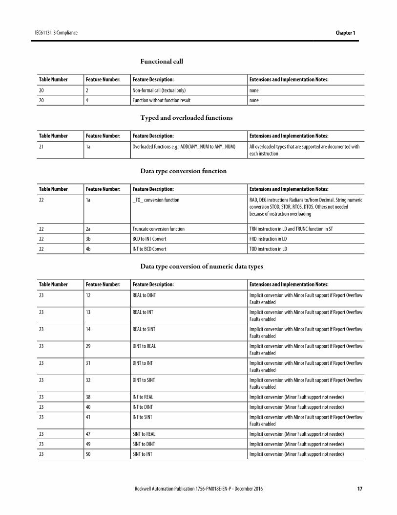
Functional call
Table Number Feature Number: Feature Description: Extensions and Implementation Notes:
20 2 Non-formal call (textual only) none
20 4 Function without function result none
Typed and overloaded functions
Table Number Feature Number: Feature Description: Extensions and Implementation Notes:
21 1a Overloaded functions e.g., ADD(ANY_NUM to ANY_NUM) All overloaded types that are supported are documented with each instruction
Data type conversion function
Table Number Feature Number: Feature Description: Extensions and Implementation Notes:
22 1a _TO_ conversion function RAD, DEG instructions Radians to/from Decimal. String numeric conversion STOD, STOR, RTOS, DTOS. Others not needed because of instruction overloading
22 2a Truncate conversion function TRN instruction in LD and TRUNC function in ST
22 3b BCD to INT Convert FRD instruction in LD
22 4b INT to BCD Convert TOD instruction in LD
Data type conversion of numeric data types
Table Number Feature Number: Feature Description: Extensions and Implementation Notes:
23 12 REAL to DINT Implicit conversion with Minor Fault support if Report Overflow Faults enabled
23 13 REAL to INT Implicit conversion with Minor Fault support if Report Overflow Faults enabled
23 14 REAL to SINT Implicit conversion with Minor Fault support if Report Overflow Faults enabled
23 29 DINT to REAL Implicit conversion with Minor Fault support if Report Overflow Faults enabled
23 31 DINT to INT Implicit conversion with Minor Fault support if Report Overflow Faults enabled
23 32 DINT to SINT Implicit conversion with Minor Fault support if Report Overflow Faults enabled
23 38 INT to REAL Implicit conversion (Minor Fault support not needed)
23 40 INT to DINT Implicit conversion (Minor Fault support not needed)
23 41 INT to SINT Implicit conversion with Minor Fault support if Report Overflow Faults enabled
23 47 SINT to REAL Implicit conversion (Minor Fault support not needed)
23 49 SINT to DINT Implicit conversion (Minor Fault support not needed)
23 50 SINT to INT Implicit conversion (Minor Fault support not needed)
Chapter 1 IEC61131-3 Compliance
18 Rockwell Automation Publication 1756-PM018E-EN-P - December 2016
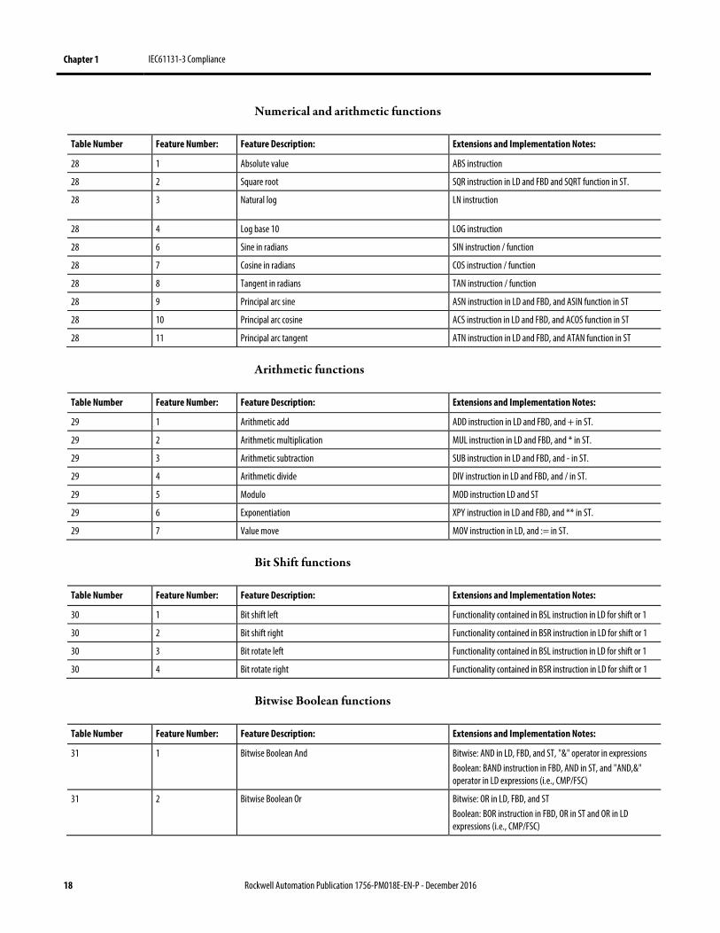
Numerical and arithmetic functions
Table Number Feature Number: Feature Description: Extensions and Implementation Notes:
28 1 Absolute value ABS instruction
28 2 Square root SQR instruction in LD and FBD and SQRT function in ST.
28 3 Natural log LN instruction
28 4 Log base 10 LOG instruction
28 6 Sine in radians SIN instruction / function
28 7 Cosine in radians COS instruction / function
28 8 Tangent in radians TAN instruction / function
28 9 Principal arc sine ASN instruction in LD and FBD, and ASIN function in ST
28 10 Principal arc cosine ACS instruction in LD and FBD, and ACOS function in ST
28 11 Principal arc tangent ATN instruction in LD and FBD, and ATAN function in ST
Arithmetic functions
Table Number Feature Number: Feature Description: Extensions and Implementation Notes:
29 1 Arithmetic add ADD instruction in LD and FBD, and + in ST.
29 2 Arithmetic multiplication MUL instruction in LD and FBD, and * in ST.
29 3 Arithmetic subtraction SUB instruction in LD and FBD, and - in ST.
29 4 Arithmetic divide DIV instruction in LD and FBD, and / in ST.
29 5 Modulo MOD instruction LD and ST
29 6 Exponentiation XPY instruction in LD and FBD, and ** in ST.
29 7 Value move MOV instruction in LD, and := in ST.
Bit Shift functions
Table Number Feature Number: Feature Description: Extensions and Implementation Notes:
30 1 Bit shift left Functionality contained in BSL instruction in LD for shift or 1
30 2 Bit shift right Functionality contained in BSR instruction in LD for shift or 1
30 3 Bit rotate left Functionality contained in BSL instruction in LD for shift or 1
30 4 Bit rotate right Functionality contained in BSR instruction in LD for shift or 1
Bitwise Boolean functions
Table Number Feature Number: Feature Description: Extensions and Implementation Notes:
31 1 Bitwise Boolean And Bitwise: AND in LD, FBD, and ST, "&" operator in expressions Boolean: BAND instruction in FBD, AND in ST, and "AND,&" operator in LD expressions (i.e., CMP/FSC)
31 2 Bitwise Boolean Or Bitwise: OR in LD, FBD, and ST Boolean: BOR instruction in FBD, OR in ST and OR in LD expressions (i.e., CMP/FSC)

IEC61131-3 Compliance Chapter 1
Rockwell Automation Publication 1756-PM018E-EN-P - December 2016 19
Table Number Feature Number: Feature Description: Extensions and Implementation Notes:
31 3 Bitwise Boolean Exclusive Or Bitwise: XOR in LD, FBD, and ST, Boolean: BXOR instruction in FBD, XOR in ST and XOR in LD expressions (i.e., CMP/FSC)
31 4 Bitwise Boolean Not Bitwise: NOT in LD, FBD, and ST, Boolean: BNOT instruction in FBD, NOT in ST and NOT in LD expressions (i.e., CMP/FSC)
Select functions
Table Number Feature Number: Feature Description: Extensions and Implementation Notes:
32 1 SELECT SEL instruction in FBD
32 2 Maximum select MAX Functionality contained in ESEL instruction in FBD and ST
32 3 Minimum select MIN Functionality contained in ESEL instruction in FBD and ST
32 4 High/Low limit LIMIT HLL instruction in FBD and ST
32 5 Multiplexer MUX MUX instruction in FBD
Comparison functions
Table Number Feature Number: Feature Description: Extensions and Implementation Notes:
33 1 Comparison greater-than GRT instruction in LD and FBD, and > in ST.
33 2 Comparison greater-than or equal GRE instruction in LD and FBD, and >= in ST.
33 3 Comparison equal EQU instruction in LD and FBD, and = in ST.
33 4 Comparison less-than LES instruction in LD and FBD, and < in ST.
33 5 Comparison less-than or equal LEQ instruction in LD and FBD, and <= in ST.
33 6 Comparison not equal NEQ instruction in LD and FBD, and <> in ST.
Character string functions
Table Number Feature Number: Feature Description: Extensions and Implementation Notes:
34 1 String length LEN Use STRING.LEN or SIZE in LD and ST.
34 4 Middle string MID MID instruction in LD and ST
34 5 String concatenation CONCAT CONCAT instruction in LD and ST
34 6 String insert INSERT INSERT instruction in LD and ST
34 7 String delete DELETE DELETE instruction in LD and ST
34 9 Find string FIND FIND instruction in LD and ST
Function block type declaration
Table Number Feature Number: Feature Description: Extensions and Implementation Notes:
40 1 Declaration of function block type Add On Instructions provide Function Block equivalent
40 2a Declaration of inputs Add On Instructions provide Function Block equivalent

Chapter 1 IEC61131-3 Compliance
20 Rockwell Automation Publication 1756-PM018E-EN-P - December 2016
Table Number Feature Number: Feature Description: Extensions and Implementation Notes:
40 2b Declaration of outputs Add On Instructions provide Function Block equivalent
40 2c Declaration of in-outs Add On Instructions provide Function Block equivalent
40 2e Declaration of static variables Add On Instructions provide Function Block equivalent
40 3a Initialization of inputs Add On Instructions provide Function Block equivalent
40 3b Initialization of outputs Add On Instructions provide Function Block equivalent
40 3c Initializations of static variables Add On Instructions provide Function Block equivalent
Function block instance declaration
Table Number Feature Number: Feature Description: Extensions and Implementation Notes:
41 1 Declaration of function block instances Add On Instructions provide Function Block equivalent
41 2 Declaration of function block instances with initialization Add On Instructions provide Function Block equivalent
Function block call
Table Number Feature Number: Feature Description: Extensions and Implementation Notes:
42 1 Complete formal call (textual only) Add on Instructions provide Function Block equivalent. User selectable.
42 2 Incomplete formal call (textual only) Add on Instructions provide Function Block equivalent. In-outs are required. User Selectable.
42 3 Graphical call Add on Instructions provide Function Block equivalent. EN/ENO are optional.
42 6a Textual call with separate assignment of input Add on Instructions provide Function Block equivalent
42 7 Textual output read after FB call Add on Instructions provide Function Block equivalent
42 10a Textual call with function block instance name as VAR_IN_OUT
Add on Instructions provide Function Block equivalent
42 10b Graphical call with function block instance name as VAR_IN_OUT
Add on Instructions provide Function Block equivalent
Standard bistable
Table Number Feature Number: Feature Description: Extensions and Implementation Notes:
43 1b Bistable set dominant (long names) SETD instruction in FBD and ST
43 2b Bistable reset dominant (long names) RESD instruction in FBD and ST
Standard edge detection function blocks
Table Number Feature Number: Feature Description: Extensions and Implementation Notes:
44 1 Rising edge detector OSR instruction in LD and OSRI instruction in FBD and ST
44 2 Falling edge detector OSF instruction in LD and OSFI instruction in FBD and ST

IEC61131-3 Compliance Chapter 1
Rockwell Automation Publication 1756-PM018E-EN-P - December 2016 21
Standard counter function blocks
Table Number Feature Number: Feature Description: Extensions and Implementation Notes:
45 1b Up-counter Functionality contained in CTU and RES instructions in LD and in CTUD instruction in FBD and ST
45 2b Down-counter Functionality contained in CTD and RES instructions in LD and in CTUD instruction in FBD and ST
45 3b UpDown-counter CTUD instruction in FBD and ST
Standard timer function blocks
Table Number Feature Number: Feature Description: Extensions and Implementation Notes:
46 2b On-delay timer using TIME Functionality contained in TON instruction in LD and TONR instruction in FBD and ST
46 3b Off-delay timer using TIME Functionality contained in TOF instruction in LD and TOFR instruction in FBD and ST
Program declaration
Table Number Feature Number: Feature Description: Extensions and Implementation Notes:
47 1 Declaration of a program none
47 2a Declaration of inputs none
47 2b Declaration of outputs none
47 2c Declaration of in-outs none
47 2e Declaration of static variables none
47 3a Initialization of inputs none
47 3b Initialization of outputs none
47 3c Initialization of static variables none
SFC step
Table Number Feature Number: Feature Description: Extensions and Implementation Notes:
54 1a SFC Step none
54 1b SFC initial Step none
54 2a SFC Step Textual Import/export, step name is specified using the format "Operand := step_name"
54 2b SFC initial Step textual Import/export, uses "InitialStep" Parameter and step name is specified using the format "Operand := step_name"
54 3a SFC Step Flag general form Step backing tag
54 4 Step elapsed time general form Step backing tag
SFC transition and transition conditions
Table Number Feature Number: Feature Description: Extensions and Implementation Notes:
55 1 Transition using ST none
Chapter 1 IEC61131-3 Compliance
22 Rockwell Automation Publication 1756-PM018E-EN-P - December 2016
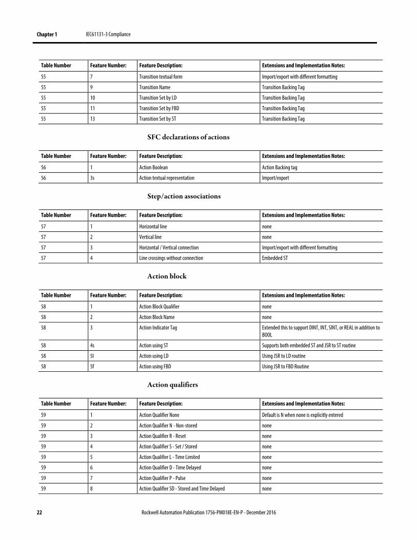
Table Number Feature Number: Feature Description: Extensions and Implementation Notes:
55 7 Transition textual form Import/export with different formatting
55 9 Transition Name Transition Backing Tag
55 10 Transition Set by LD Transition Backing Tag
55 11 Transition Set by FBD Transition Backing Tag
55 13 Transition Set by ST Transition Backing Tag
SFC declarations of actions
Table Number Feature Number: Feature Description: Extensions and Implementation Notes:
56 1 Action Boolean Action Backing tag
56 3s Action textual representation Import/export
Step/action associations
Table Number Feature Number: Feature Description: Extensions and Implementation Notes:
57 1 Horizontal line none
57 2 Vertical line none
57 3 Horizontal / Vertical connection Import/export with different formatting
57 4 Line crossings without connection Embedded ST
Action block
Table Number Feature Number: Feature Description: Extensions and Implementation Notes:
58 1 Action Block Qualifier none
58 2 Action Block Name none
58 3 Action Indicator Tag Extended this to support DINT, INT, SINT, or REAL in addition to BOOL
58 4s Action using ST Supports both embedded ST and JSR to ST routine
58 5I Action using LD Using JSR to LD routine
58 5f Action using FBD Using JSR to FBD Routine
Action qualifiers
Table Number Feature Number: Feature Description: Extensions and Implementation Notes:
59 1 Action Qualifier None Default is N when none is explicitly entered
59 2 Action Qualifier N - Non-stored none
59 3 Action Qualifier R - Reset none
59 4 Action Qualifier S - Set / Stored none
59 5 Action Qualifier L - Time Limited none
59 6 Action Qualifier D - Time Delayed none
59 7 Action Qualifier P - Pulse none
59 8 Action Qualifier SD - Stored and Time Delayed none

IEC61131-3 Compliance Chapter 1
Rockwell Automation Publication 1756-PM018E-EN-P - December 2016 23
Table Number Feature Number: Feature Description: Extensions and Implementation Notes:
59 9 Action Qualifier DS - Delayed and Stored none
59 10 Action Qualifier SL - Stored and time limited none
59 11 Action Qualifier P1 - Pulse Rising Edge none
59 12 Action Qualifier P0 - Pulse Falling Edge none
Action control features
Table Number Feature Number: Feature Description: Extensions and Implementation Notes:
60 1 Action Control with final scan none
60 2 Action Control without final scan none
Sequence evolution - graphical
Table Number Feature Number: Feature Description: Extensions and Implementation Notes:
61 1 SFC Single Sequence none
61 2a SFC Divergence of sequence with left to right priority Use of line connections vs. asterisk
61 2b SFC Divergence of sequence with numbered branches none
61 2c SFC Divergence of sequence with mutual exclusion none
61 3 SFC Convergence of sequence none
61 4a SFC Simultaneous divergence after a single transition none
61 4b SFC Simultaneous divergence after convergence none
61 4c SFC Simultaneous convergence before a single transition none
61 4d SFC Simultaneous convergence before a sequence selection none
61 5a, b, c SFC Sequence Skip none
61 6a, b, c SFC Sequence Loop none
61 7 SFC Loop directional arrows When wire is hidden
Configuration and resource declaration
Table Number Feature Number: Feature Description: Extensions and Implementation Notes:
62 3 Resource declaration Controller is our equivalent
62 3a Textual association with PROGRAMs
62 3b Textual association with function blocks
62 4 Global variables Controller scope variables
62 5a Periodic TASK none
62 5b Non-periodic TASK none
62 6a Program to Task association Schedule a Program to a Task
62 6c Program without tasks Unscheduled Programs
Chapter 1 IEC61131-3 Compliance
24 Rockwell Automation Publication 1756-PM018E-EN-P - December 2016
Task
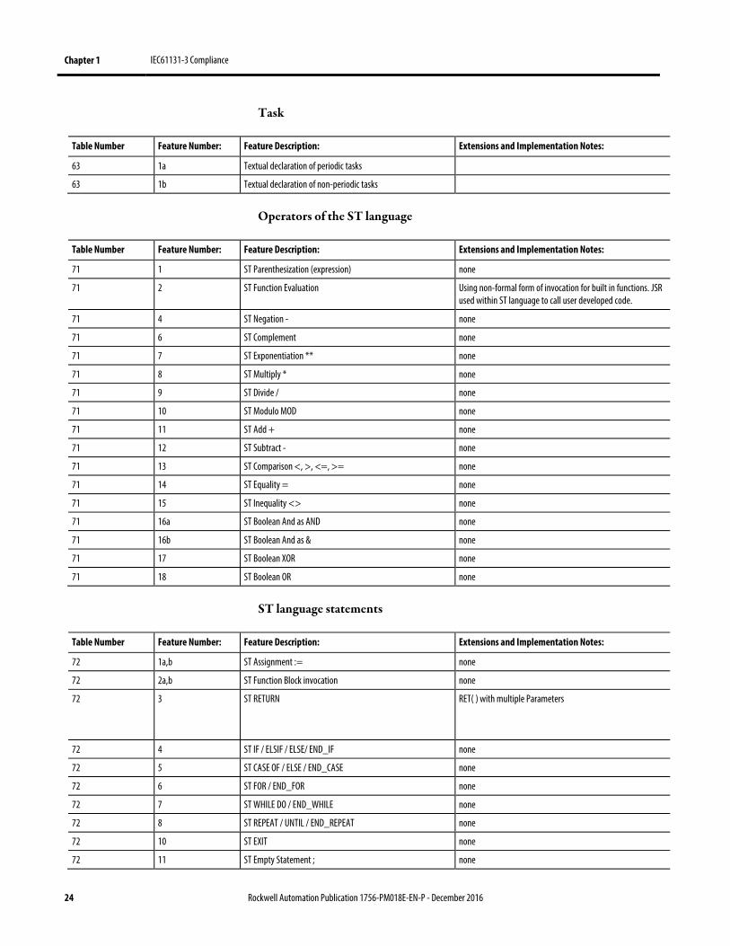
Table Number Feature Number: Feature Description: Extensions and Implementation Notes:
63 1a Textual declaration of periodic tasks
63 1b Textual declaration of non-periodic tasks
Operators of the ST language
Table Number Feature Number: Feature Description: Extensions and Implementation Notes:
71 1 ST Parenthesization (expression) none
71 2 ST Function Evaluation Using non-formal form of invocation for built in functions. JSR used within ST language to call user developed code.
71 4 ST Negation - none
71 6 ST Complement none
71 7 ST Exponentiation ** none
71 8 ST Multiply * none
71 9 ST Divide / none
71 10 ST Modulo MOD none
71 11 ST Add + none
71 12 ST Subtract - none
71 13 ST Comparison <, >, <=, >= none
71 14 ST Equality = none
71 15 ST Inequality <> none
71 16a ST Boolean And as AND none
71 16b ST Boolean And as & none
71 17 ST Boolean XOR none
71 18 ST Boolean OR none
ST language statements
Table Number Feature Number: Feature Description: Extensions and Implementation Notes:
72 1a,b ST Assignment := none
72 2a,b ST Function Block invocation none
72 3 ST RETURN RET( ) with multiple Parameters
72 4 ST IF / ELSIF / ELSE/ END_IF none
72 5 ST CASE OF / ELSE / END_CASE none
72 6 ST FOR / END_FOR none
72 7 ST WHILE DO / END_WHILE none
72 8 ST REPEAT / UNTIL / END_REPEAT none
72 10 ST EXIT none
72 11 ST Empty Statement ; none
IEC61131-3 Compliance Chapter 1
Rockwell Automation Publication 1756-PM018E-EN-P - December 2016 25
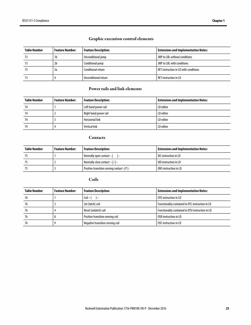
Graphic execution control elements
Table Number Feature Number: Feature Description: Extensions and Implementation Notes:
73 1b Unconditional jump JMP to LBL without conditions
73 2b Conditional jump JMP to LBL with conditions
73 3a Conditional return RET instruction in LD with conditions
73 4 Unconditional return RET instruction in LD
Power rails and link elements
Table Number Feature Number: Feature Description: Extensions and Implementation Notes:
74 1 Left hand power rail LD editor
74 2 Right hand power rail LD editor
74 3 Horizontal link LD editor
74 4 Vertical link LD editor
Contacts
Table Number Feature Number: Feature Description: Extensions and Implementation Notes:
75 1 Normally open contact --| |-- XIC instruction in LD
75 2 Normally close contact --| / |-- XIO instruction in LD
75 3 Positive transition sensing contact -| P |- ONS instruction in LD
Coils
Table Number Feature Number: Feature Description: Extensions and Implementation Notes:
76 1 Coil --( )-- OTE instruction in LD
76 3 Set (latch) coil Functionality contained in OTL instruction in LD
76 4 Reset (unlatch) coil Functionality contained in OTU instruction in LD
76 8 Positive transition sensing coil OSR instruction in LD
76 9 Negative transition sensing coil OSF instruction in LD

Rockwell Automation Publication 1756-PM018E-EN-P - December 2016 27
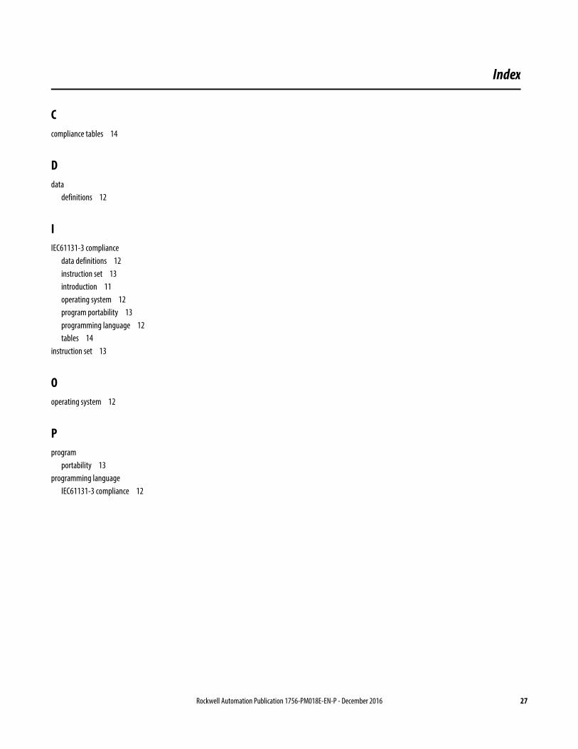
C compliance tables 14
D data
definitions 12
I IEC61131-3 compliance
data definitions 12 instruction set 13 introduction 11 operating system 12 program portability 13 programming language 12 tables 14
instruction set 13
O operating system 12
P program
portability 13 programming language
IEC61131-3 compliance 12
Index

Rockwell Automation Publication 1756-PM018E-EN-P - December 2016
Supersedes Publication 1756-PM018D-EN-P - June 2016 Copyright © 2016 Rockwell Automation, Inc. All rights reserved. Printed in the U.S.A.
Rockwell Automation support
Rockwell Automation provides technical information on the web to assist you in using its products. At http://www.rockwellautomation.com/support you can find technical and application notes, sample code, and links to software service packs. You can also visit our Support Center at https://rockwellautomation.custhelp.com for software updates, support chats and forums, technical information, FAQs, and to sign up for product notification updates.
In addition, we offer multiple support programs for installation, configuration, and troubleshooting. For more information, contact your local distributor or Rockwell Automation representative, or visit http://www.rockwellautomation.com/services/online-phone.
Installation assistance
If you experience a problem within the first 24 hours of installation, review the information that is contained in this manual. You can contact Customer Support for initial help in getting your product up and running.
United States or Canada 1.440.646.3434
Outside United States or Canada Use the Worldwide Locator available at http://www.rockwellautomation.com/locations, or contact your local Rockwell Automation representative.
New product satisfaction return
Rockwell Automation tests all of its products to ensure that they are fully operational when shipped from the manufacturing facility. However, if your product is not functioning and needs to be returned, follow these procedures.
United States Contact your distributor. You must provide a Customer Support case number (call the phone number above to obtain one) to your distributor to complete the return process.
Outside United States Please contact your local Rockwell Automation representative for the return procedure.
Documentation feedback Your comments will help us serve your documentation needs better. If you have any suggestions on how to improve this document, complete the
feedback form, publication RA-DU002.