Embed Size (px)
Citation preview
www.mikado-heli.de
LOGO 400 V-Stabi
© Mikado Modellhubschrauber, V1.0
Manual
Mikado Modellhubschrauber • Friedrich-Klausing-Straße 2 • 14469 Potsdam • GermanyPhone +49 (0)331 23749-0 • Fax +49 (0)331 23749-11 • www.mikado-heli.de
Manual LOGO 400 V-Stabi Page 2 ©Mikado Modellhubschrauber
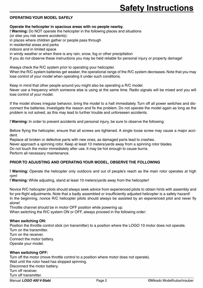
Safety InstructionsOPERATING YOUR MODEL SAFELY
Operate the helicopter in spacious areas with no people nearby.! Warning: Do NOT operate the helicopter in the following places and situations (or else you risk severe accidents):in places where children gather or people pass throughin residential areas and parksindoors and in limited spacein windy weather or when there is any rain, snow, fog or other precipitationIf you do not observe these instructions you may be held reliable for personal injury or property damage!
Always check the R/C system prior to operating your helicopter. When the R/C system batteries get weaker, the operational range of the R/C system decreases. Note that you may lose control of your model when operating it under such conditions.
Keep in mind that other people around you might also be operating a R/C model. Never use a frequency which someone else is using at the same time. Radio signals will be mixed and you will lose control of your model.
If the model shows irregular behavior, bring the model to a halt immediately. Turn off all power switches and dis-connect the batteries. Investigate the reason and fix the problem. Do not operate the model again as long as the problem is not solved, as this may lead to further trouble and unforeseen accidents.
! Warning: In order to prevent accidents and personal injury, be sure to observe the following:
Before flying the helicopter, ensure that all screws are tightened. A single loose screw may cause a major acci-dent. Replace all broken or defective parts with new ones, as damaged parts lead to crashes.Never approach a spinning rotor. Keep at least 10 meters/yards away from a spinning rotor blades. Do not touch the motor immediately after use. It may be hot enough to cause burns. Perform all necessary maintenance.
PRIOR TO ADJUSTING AND OPERATING YOUR MODEL, OBSERVE THE FOLLOWING
! Warning: Operate the helicopter only outdoors and out of people’s reach as the main rotor operates at high rpm!! Warning: While adjusting, stand at least 10 meters/yards away from the helicopter!
Novice R/C helicopter pilots should always seek advice from experienced pilots to obtain hints with assembly and for pre-flight adjustments. Note that a badly assembled or insufficiently adjusted helicopter is a safety hazard!In the beginning, novice R/C helicopter pilots should always be assisted by an experienced pilot and never fly alone!Throttle channel should be in motor OFF position while powering up.When switching the R/C system ON or OFF, always proceed in the following order:
When switching ON:Position the throttle control stick (on transmitter) to a position where the LOGO 10 motor does not operate. Turn on the transmitter. Turn on the receiver.Connect the motor battery. Operate your model.
When switching OFF:Turn off the motor (move throttle control to a position where motor does not operate).Wait until the rotor head has stopped spinning.Disconnect the motor battery.Turn off receiver.Turn off transmitter.
Manual LOGO 400 V-Stabi Page 3 ©Mikado Modellhubschrauber
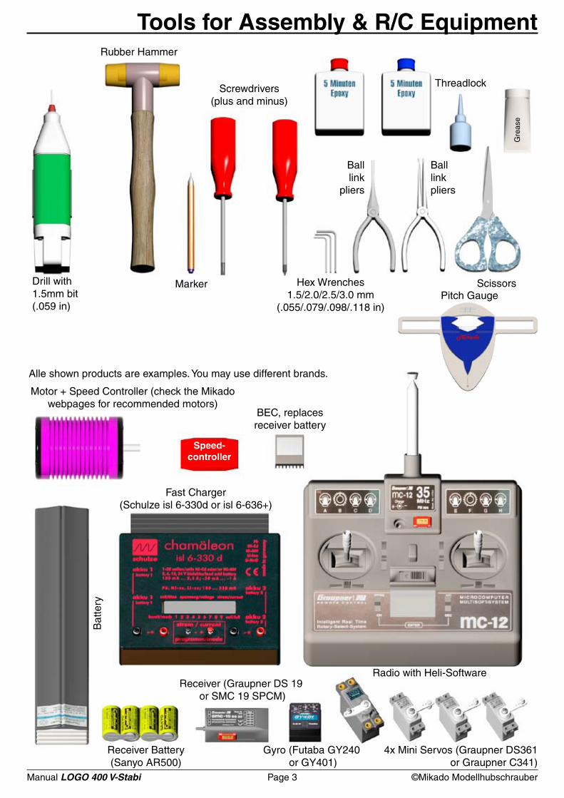
Speed-controller
Tools for Assembly & R/C Equipment
Radio with Heli-Software
4x Mini Servos (Graupner DS361or Graupner C341)
Receiver Battery (Sanyo AR500)
Bat
tery
Receiver (Graupner DS 19 or SMC 19 SPCM)
Gyro (Futaba GY240 or GY401)
Fast Charger(Schulze isl 6-330d or isl 6-636+)
Motor + Speed Controller (check the Mikado webpages for recommended motors)
Alle shown products are examples. You may use different brands.
BEC, replaces receiver battery
Scissors
Rubber Hammer
Drill with 1.5mm bit(.059 in)
Marker
Screwdrivers (plus and minus)
Hex Wrenches1.5/2.0/2.5/3.0 mm
(.055/.079/.098/.118 in)
Balllink
pliers
Threadlock
Balllinkpliers
Gre
ase
Pitch Gauge
Manual LOGO 400 V-Stabi Page 4 ©Mikado Modellhubschrauber
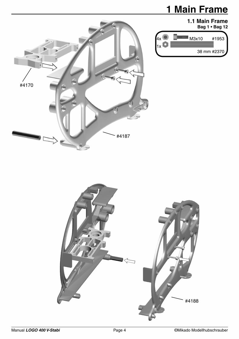
#4187
#4170
#4188
4x M3x10 #1953
1x 38 mm #2370
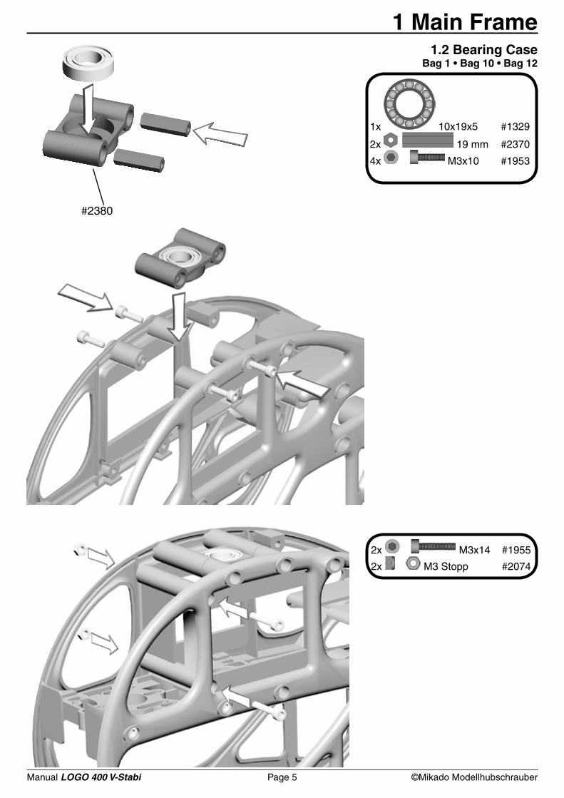
1 Main Frame1.1 Main Frame
Bag 1 • Bag 12
Manual LOGO 400 V-Stabi Page 5 ©Mikado Modellhubschrauber
1x 10x19x5 #1329
2x 19 mm #2370
4x M3x10 #1953
#2380
2x M3x14 #1955
2x M3 Stopp #2074
1 Main Frame1.2 Bearing Case
Bag 1 • Bag 10 • Bag 12
Manual LOGO 400 V-Stabi Page 6 ©Mikado Modellhubschrauber
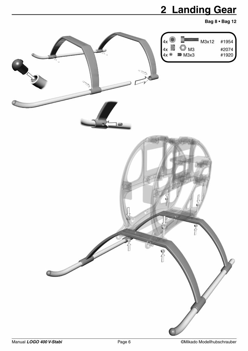
4x M3x12 #1954
4x M3 #20744x M3x3 #1920
2 Landing GearBag 8 • Bag 12
Manual LOGO 400 V-Stabi Page 7 ©Mikado Modellhubschrauber
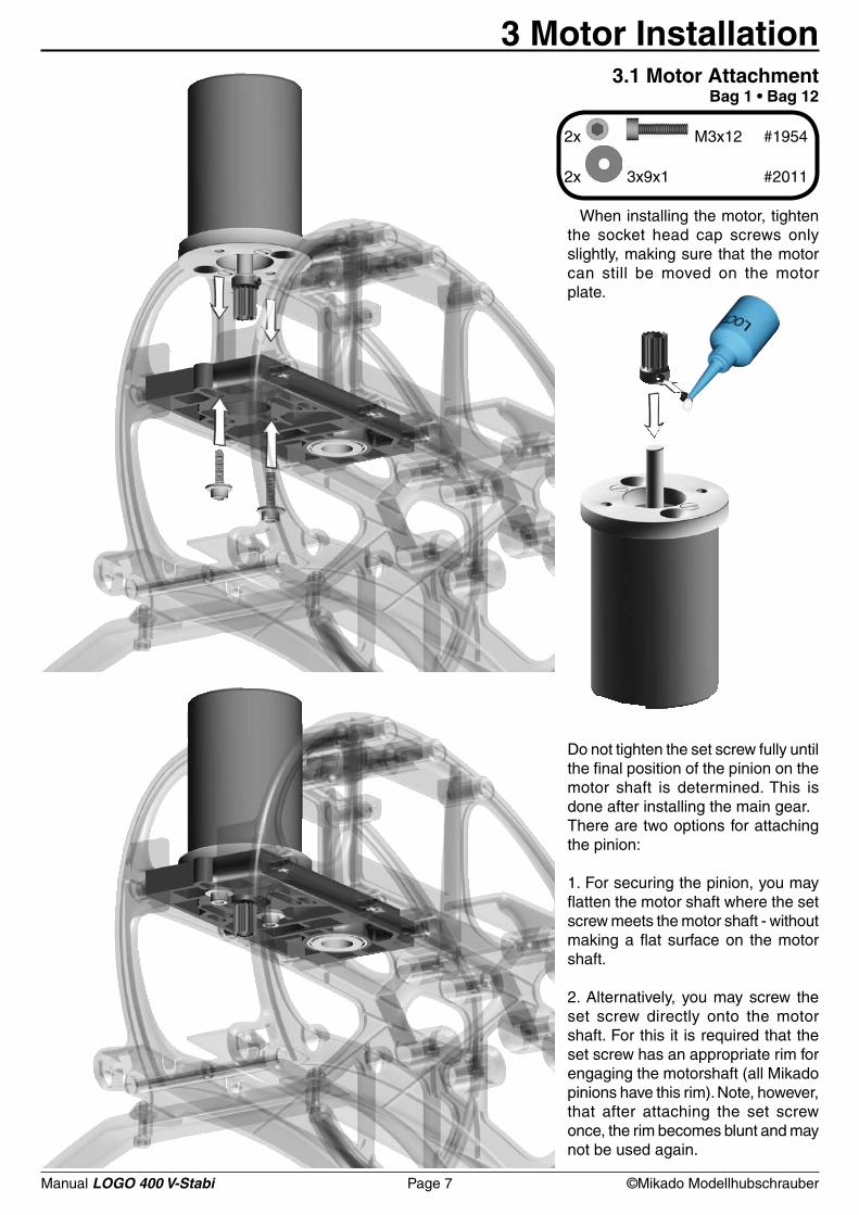
2x M3x12 #1954
2x 3x9x1 #2011
3 Motor Installation3.1 Motor Attachment
Bag 1 • Bag 12
When installing the motor, tighten the socket head cap screws only slightly, making sure that the motor can still be moved on the motor plate.
Do not tighten the set screw fully until the final position of the pinion on the motor shaft is determined. This is done after installing the main gear. There are two options for attaching the pinion:
1. For securing the pinion, you may flatten the motor shaft where the set screw meets the motor shaft - without making a flat surface on the motor shaft.
2. Alternatively, you may screw the set screw directly onto the motor shaft. For this it is required that the set screw has an appropriate rim for engaging the motorshaft (all Mikado pinions have this rim). Note, however, that after attaching the set screw once, the rim becomes blunt and may not be used again.
Manual LOGO 400 V-Stabi Page 8 ©Mikado Modellhubschrauber
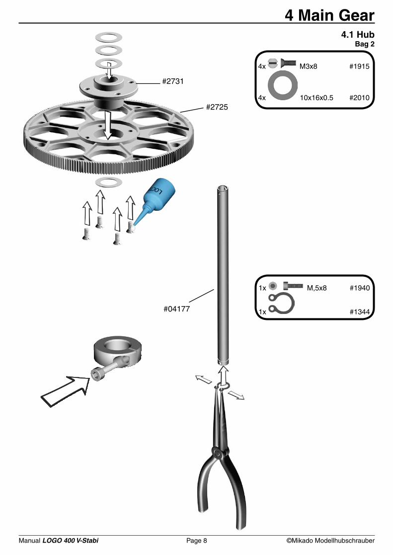
#2731
#2725
4x M3x8 #1915
4x 10x16x0.5 #2010
1x M,5x8 #1940
1x #1344#04177
4 Main Gear4.1 Hub
Bag 2
Manual LOGO 400 V-Stabi Page 9 ©Mikado Modellhubschrauber
4 Main Gear
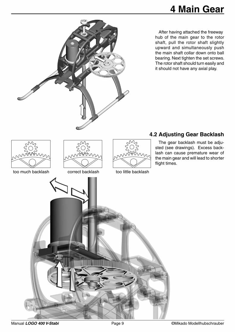
After having attached the freeway hub of the main gear to the rotor shaft, pull the rotor shaft slightly upward and simultaneously push the main shaft collar down onto ball bearing. Next tighten the set screws. The rotor shaft should turn easily and it should not have any axial play.
4.2 Adjusting Gear BacklashThe gear backlash must be adju-
sted (see drawings). Excess back-lash can cause premature wear of the main gear and will lead to shorter flight times.
too much backlash correct backlash too little backlash
Manual LOGO 400 V-Stabi Page 10 ©Mikado Modellhubschrauber
# 4189
# 4181
#2467
#2476
#2466
#2189
#4150
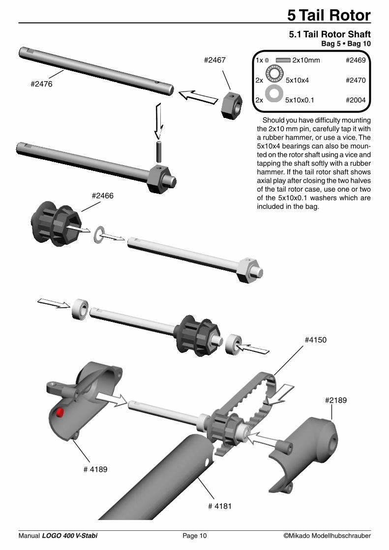
1x 2x10mm #2469
2x 5x10x4 #2470
2x 5x10x0.1 #2004
5 Tail Rotor5.1 Tail Rotor Shaft
Bag 5 • Bag 10
Should you have difficulty mounting the 2x10 mm pin, carefully tap it with a rubber hammer, or use a vice. The 5x10x4 bearings can also be moun-ted on the rotor shaft using a vice and tapping the shaft softly with a rubber hammer. If the tail rotor shaft shows axial play after closing the two halves of the tail rotor case, use one or two of the 5x10x0.1 washers which are included in the bag.
Manual LOGO 400 V-Stabi Page 11 ©Mikado Modellhubschrauber
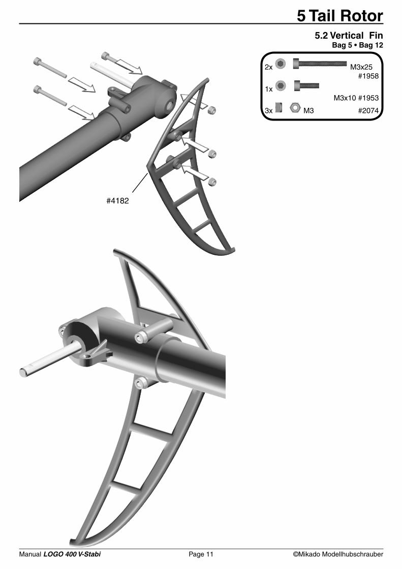
#4182
2x M3x25 #1958
1x M3x10 #1953
3x M3 #2074
5 Tail Rotor5.2 Vertical Fin
Bag 5 • Bag 12
Manual LOGO 400 V-Stabi Page 12 ©Mikado Modellhubschrauber
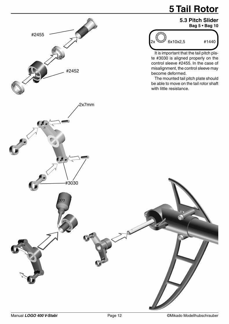
#2455
#2452
2x 6x10x2,5 #1440
#3030
2x7mm
5 Tail Rotor5.3 Pitch Slider
Bag 5 • Bag 10
It is important that the tail pitch pla-te #3030 is aligned properly on the control sleeve #2455. In the case of misalignment, the control sleeve may become deformed.
The mounted tail pitch plate should be able to move on the tail rotor shaft with little resistance.
Manual LOGO 400 V-Stabi Page 13 ©Mikado Modellhubschrauber
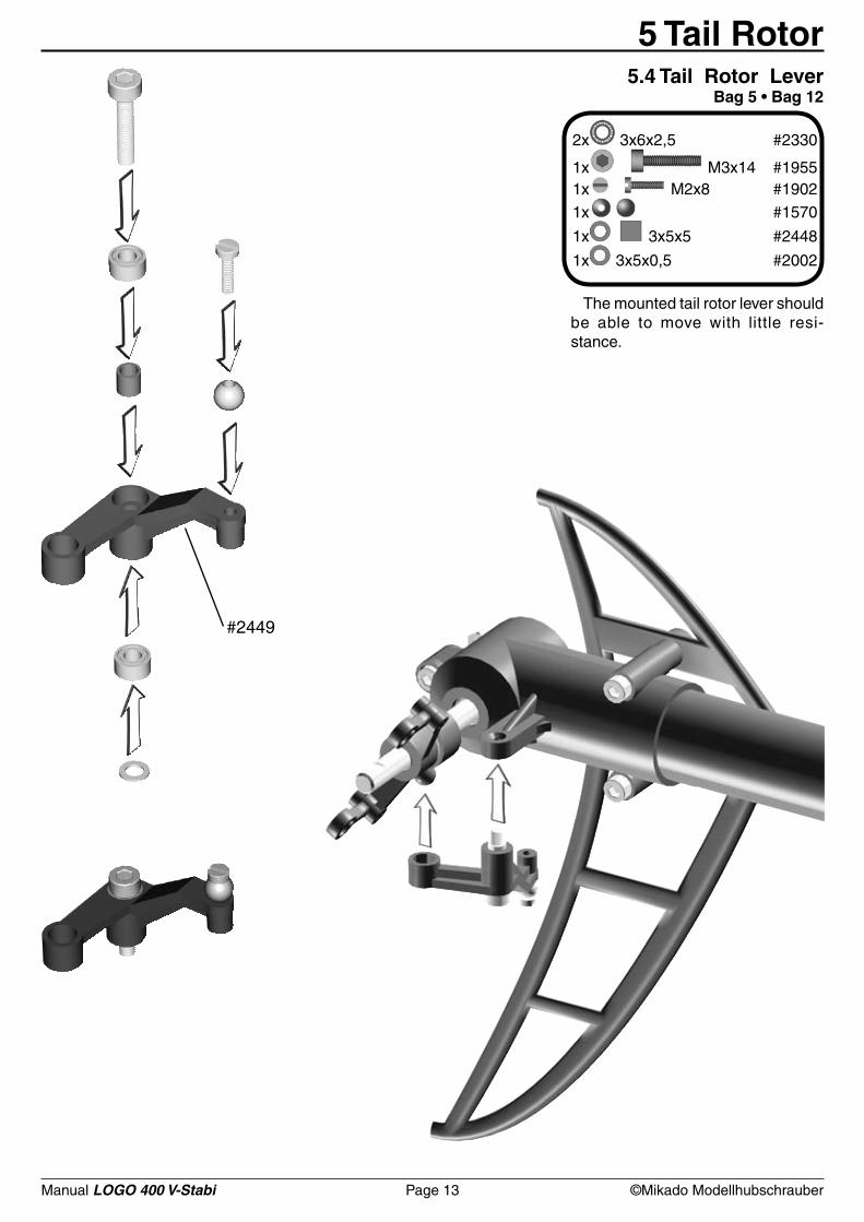
#2449
2x 3x6x2,5 #2330
1x M3x14 #19551x M2x8 #1902
1x #1570
1x 3x5x5 #2448
1x 3x5x0,5 #2002
5 Tail Rotor5.4 Tail Rotor Lever
Bag 5 • Bag 12
The mounted tail rotor lever should be able to move with little resi-stance.
Manual LOGO 400 V-Stabi Page 14 ©Mikado Modellhubschrauber
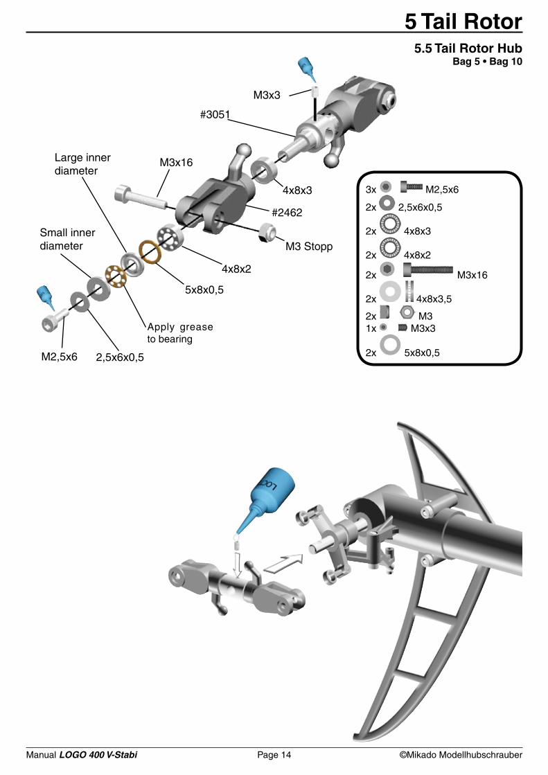
M3x3
M3x16
4x8x3
#2462
4x8x2
#3051
5x8x0,5
M2,5x6
M3 Stopp
2,5x6x0,5
3x M2,5x6
2x 2,5x6x0,5
2x 4x8x3
2x 4x8x2
2x M3x16
2x 4x8x3,5
2x M31x M3x3
2x 5x8x0,5
5 Tail Rotor5.5 Tail Rotor Hub
Bag 5 • Bag 10
Small inner diameter
Large innerdiameter
Apply grease to bearing
Manual LOGO 400 V-Stabi Page 15 ©Mikado Modellhubschrauber
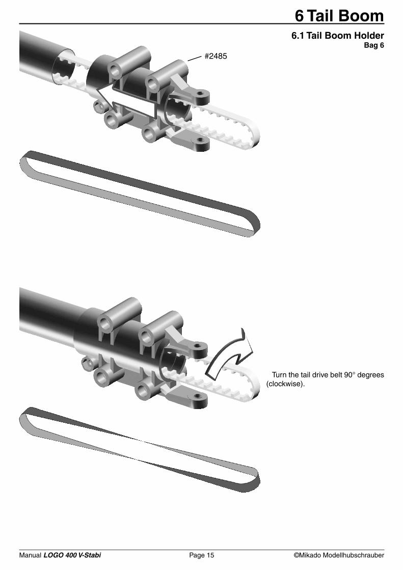
#2485
6 Tail Boom6.1 Tail Boom Holder
Bag 6
Turn the tail drive belt 90° degrees (clockwise).
Manual LOGO 400 V-Stabi Page 16 ©Mikado Modellhubschrauber
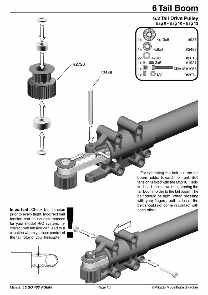
#2728
1x 4x13x5 #937
1x 4x9x4 #2489
2x 4x8x1 #20131x 3x5 #1921
1x M3x18 #1965
1x M3 #2074#2488
!
6 Tail Boom6.2 Tail Drive Pulley
Bag 6 • Bag 10 • Bag 12
Important: Check belt tension prior to every flight. Incorrect belt tension can cause disturbances for your model R/C system. In-correct belt tension can lead to a situation where you lose control of the tail rotor of your helicopter.
For tightening the belt pull the tail boom holder toward the front. Belt tension is fixed with the M3x18 sok-ket head cap screw for tightening the tail boom holder to the tail boom. The belt should be tight. When pressing with your fingers, both sides of the belt should not come in contact with each other.
Manual LOGO 400 V-Stabi Page 17 ©Mikado Modellhubschrauber
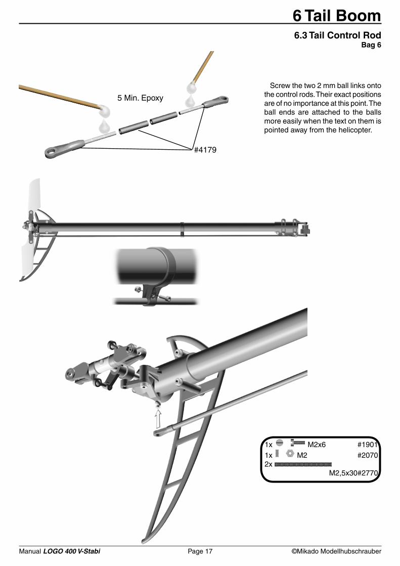
#4179
5 Min. Epoxy
1x M2x6 #19011x M2 #20702x M2,5x30#2770
6 Tail Boom6.3 Tail Control Rod
Bag 6
Screw the two 2 mm ball links onto the control rods. Their exact positions are of no importance at this point. The ball ends are attached to the balls more easily when the text on them is pointed away from the helicopter.
Manual LOGO 400 V-Stabi Page 18 ©Mikado Modellhubschrauber
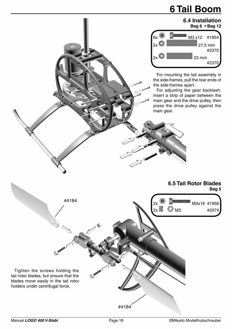
8x M3 x12 #1954
2x 27,5 mm #2370
2x 23 mm #2370
2x M3x16 #1956
2x M3 #2074
#4184
#4184
6 Tail Boom6.4 Installation
Bag 6 • Bag 12
For mounting the tail assembly in the side-frames, pull the rear ends of the side-frames apart.
For adjusting the gear backlash, insert a strip of paper between the main gear and the drive pulley, then press the drive pulley against the main gear.
6.5 Tail Rotor BladesBag 5
Tighten the screws holding the tail rotor blades, but ensure that the blades move easily in the tail rotor holders under centrifugal force.
Manual LOGO 400 V-Stabi Page 19 ©Mikado Modellhubschrauber
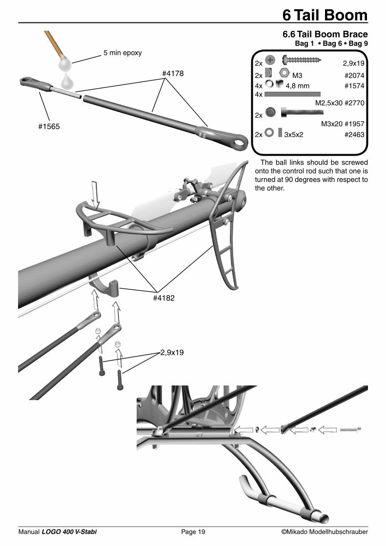
2x 2,9x19
2x M3 #20744x 4,8 mm #15744x M2,5x30 #2770
2x M3x20 #1957
2x 3x5x2 #2463
#4178
#1565
#4182
2,9x19
6 Tail Boom6.6 Tail Boom Brace
Bag 1 • Bag 6 • Bag 95 min epoxy
The ball links should be screwed onto the control rod such that one is turned at 90 degrees with respect to the other.
Manual LOGO 400 V-Stabi Page 20 ©Mikado Modellhubschrauber
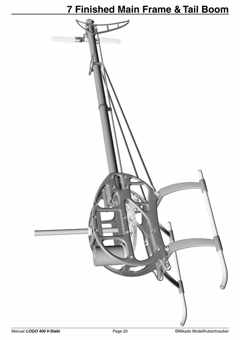
7 Finished Main Frame & Tail Boom
Manual LOGO 400 V-Stabi Page 21 ©Mikado Modellhubschrauber
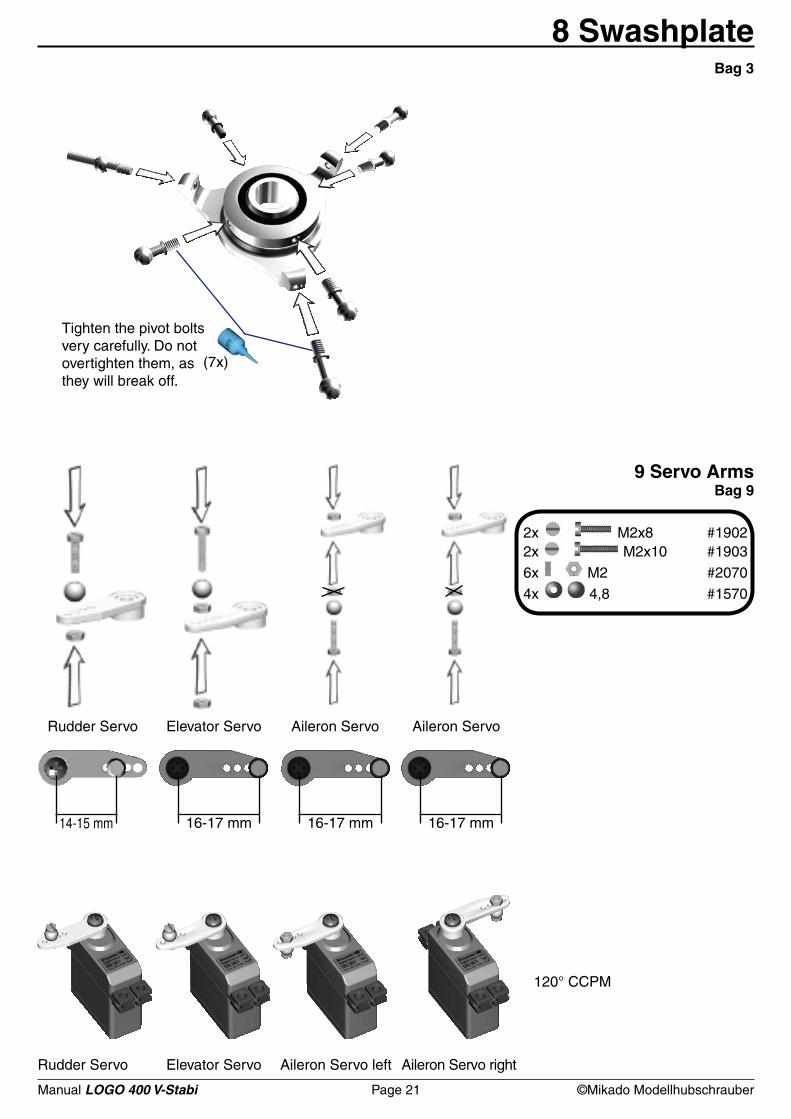
2x M2x8 #19022x M2x10 #19036x M2 #20704x 4,8 #1570
14-15 mm 16-17 mm 16-17 mm 16-17 mm
(7x)
8 SwashplateBag 3
9 Servo ArmsBag 9
Rudder Servo Elevator Servo Aileron Servo Aileron Servo
Tighten the pivot bolts very carefully. Do not overtighten them, as they will break off.
120° CCPM
Rudder Servo Elevator Servo Aileron Servo left Aileron Servo right
Manual LOGO 400 V-Stabi Page 22 ©Mikado Modellhubschrauber
14 m
m(.
472
in)
#2770
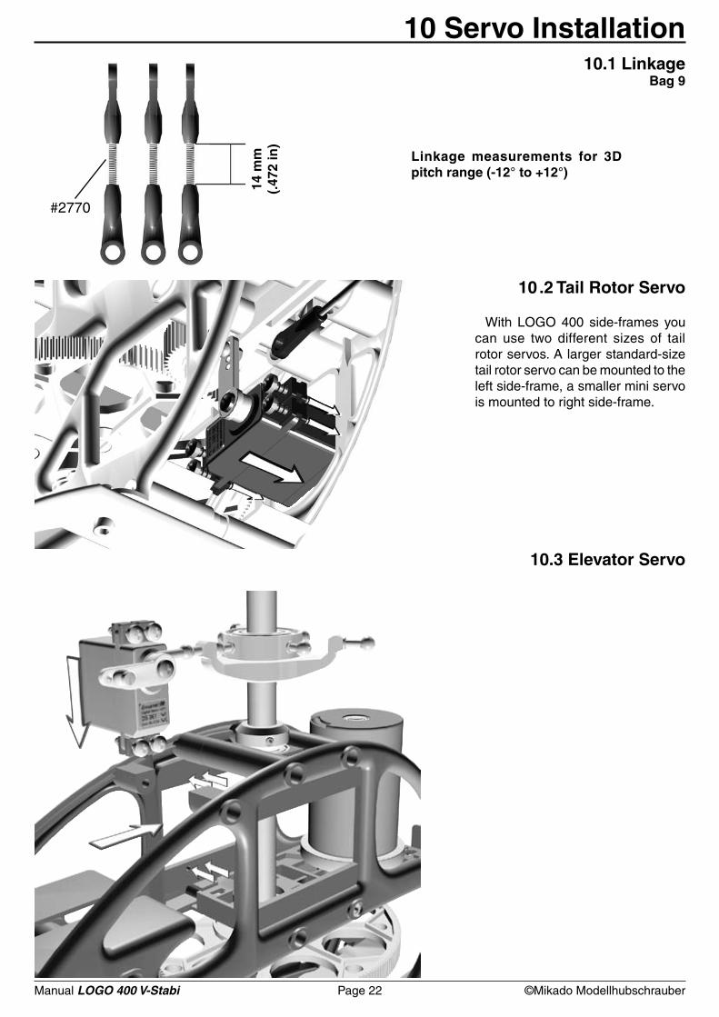
10 Servo Installation
10 .2 Tail Rotor Servo
With LOGO 400 side-frames you can use two different sizes of tail rotor servos. A larger standard-size tail rotor servo can be mounted to the left side-frame, a smaller mini servo is mounted to right side-frame.
10.3 Elevator Servo
Linkage measurements for 3D pitch range (-12° to +12°)
10.1 Linkage Bag 9
Manual LOGO 400 V-Stabi Page 23 ©Mikado Modellhubschrauber
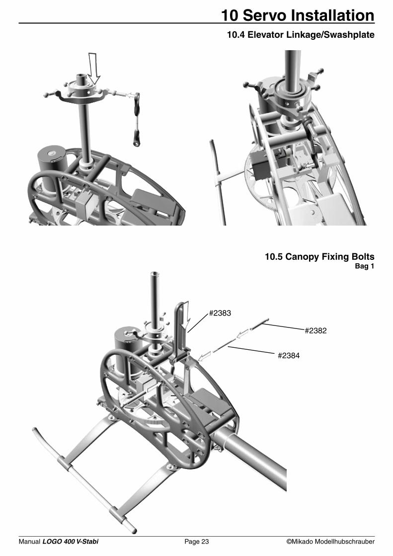
#2383
#2384
#2382
10 Servo Installation10.4 Elevator Linkage/Swashplate
10.5 Canopy Fixing BoltsBag 1
Manual LOGO 400 V-Stabi Page 24 ©Mikado Modellhubschrauber
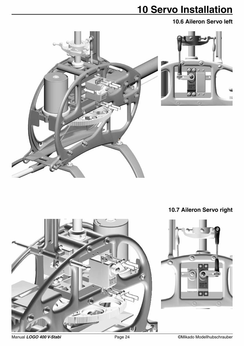
10 Servo Installation10.6 Aileron Servo left
10.7 Aileron Servo right
Manual LOGO 400 V-Stabi Page 25 ©Mikado Modellhubschrauber
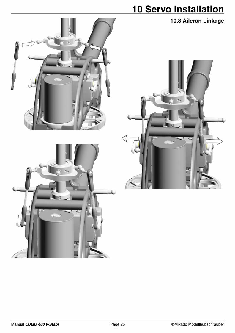
10 Servo Installation10.8 Aileron Linkage
Manual LOGO 400 V-Stabi Page 26 ©Mikado Modellhubschrauber
5x M3x8
2x 3x7
2x 2,5x7
2x 8x11x4
2x 8x11x1
4x 8x14x4
2x 6x14x5
2x 10x14x1
2x M3x10
1x M3x20
2x M3x22
2x M4x12
2x M3x24
2x 4x12x1
3x M32x Ø4,8x32x 3x12
4x 3x7x3
4x 3x6x2,5
2x 3x5x2
2x M3x14
1x M3x5
2x 3x5x0,3
M4x12
4x12x1
3x72,5x7
8x11x1
8x11x4
10x14x1
(5x)
M3x10
M3x8 (5x)
8x14x4
3x12 3x7x3
3x5x23x6x2,52x
M3x14
M3x5
3x5x0,3
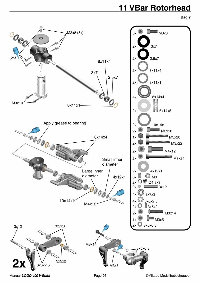
11 VBar RotorheadBag 7
Large inner diameter
Small inner diameter
Apply grease to bearing
Manual LOGO 400 V-Stabi Page 27 ©Mikado Modellhubschrauber
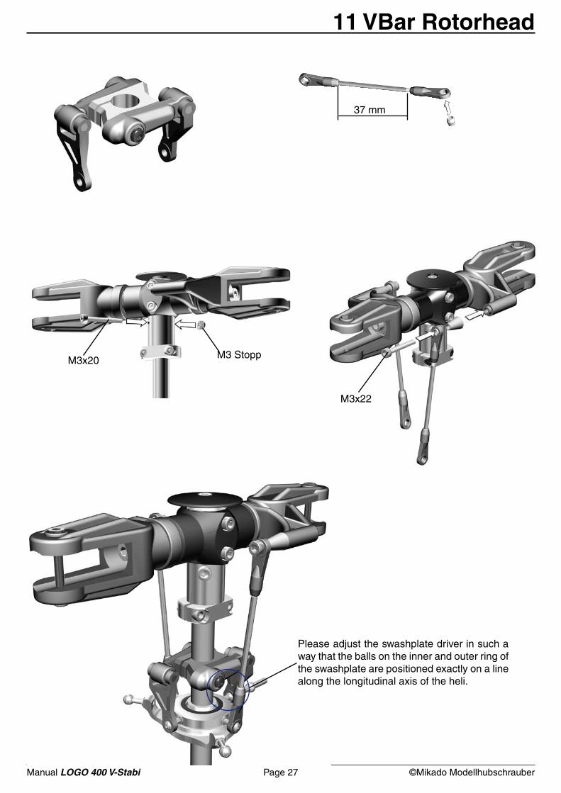
M3 StoppM3x20
37 mm
M3x22
Please adjust the swashplate driver in such a way that the balls on the inner and outer ring of the swashplate are positioned exactly on a line along the longitudinal axis of the heli.
11 VBar Rotorhead
Manual LOGO 400 V-Stabi Page 28 ©Mikado Modellhubschrauber
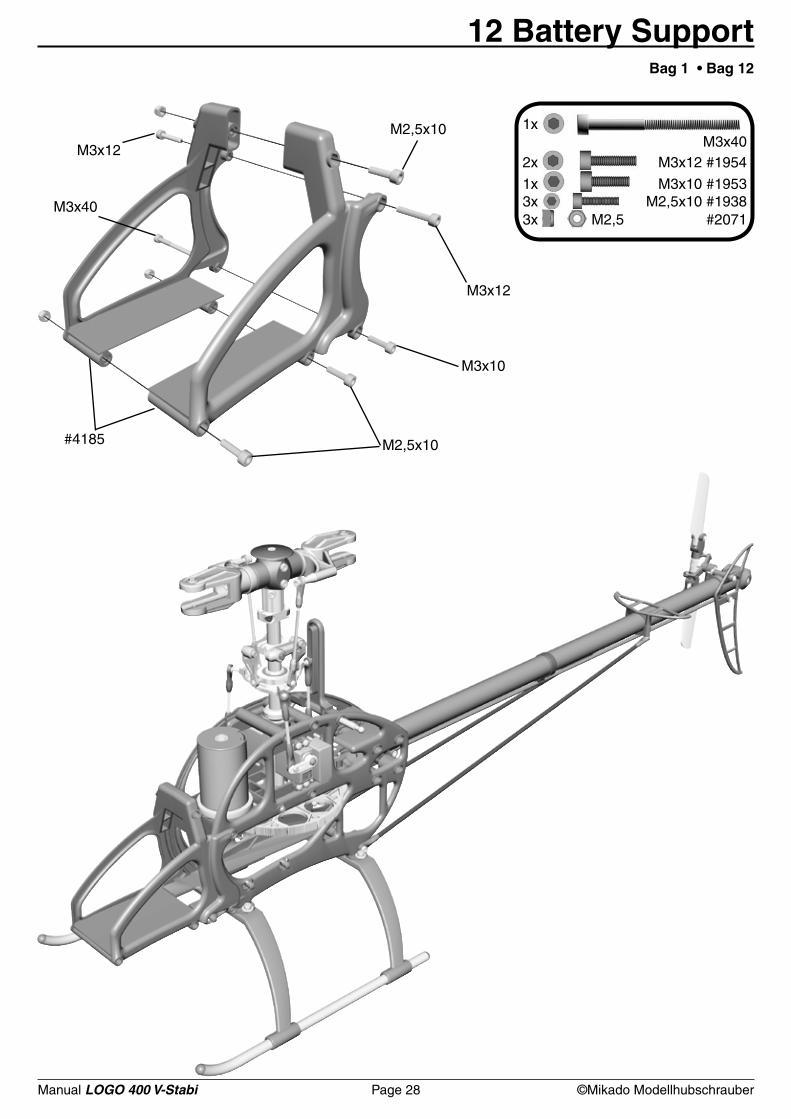
1x M3x40 2x M3x12 #1954
1x M3x10 #19533x M2,5x10 #19383x M2,5 #2071
#4185 M2,5x10
M3x10
M3x12
M2,5x10M3x12
M3x40
12 Battery SupportBag 1 • Bag 12
Manual LOGO 400 V-Stabi Page 29 ©Mikado Modellhubschrauber
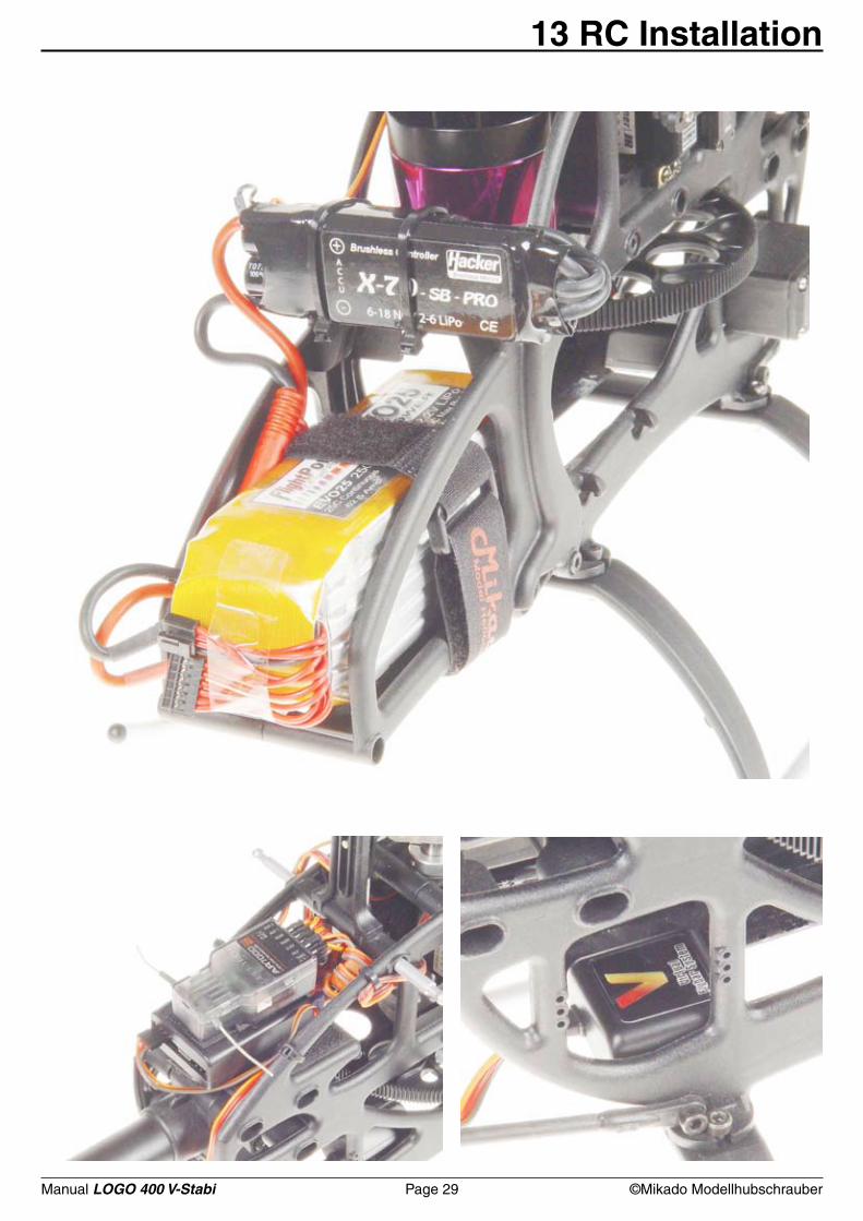
13 RC Installation
Manual LOGO 400 V-Stabi Page 30 ©Mikado Modellhubschrauber
14 VBar Programming
Manual LOGO 400 V-Stabi Page 31 ©Mikado Modellhubschrauber
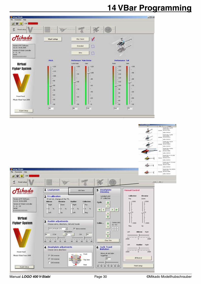
Set-up software for ready-to-fly model set-upsWith the ready-to-fly model set-ups for the LOGO Series and the T-Rex series it is now very simple to set up your model. There is just one menu for the basic parameters and the flight characteristics. It takes just a few minutes to program your VBar. Prerequisites: Before you start, you must have the set-up software installed and opened success-fully on your computer. Then connect the VBar with the receiver and the servos. Click on “Start setup” in order to switch to the setup menu. In this menu follow steps 1 to 6 and then complete the setup by clicking on “Finish setup”. During this procedure, a test mode is activated. You can check the individual control functions in the Manual Contro box.
1) Click „load preset“. Choose your helicopter model. All relevant model-specifc parameters and set-up data will be loaded into the VBar. 2) TX calibration (very important!). This step is necessary to check the effective direction of the radio. If necessary you need to switch the effective direction of your radio. Only after you have checked that all control channels of your radio are effective in correct direction you can procede with the next step here. Note that your radio must be free of any pre-programming. It is used as a simple 4-channel radio.3) This step chooses the tail servo you are using. Please adjust effective direction, servo center and servo travel.4) Check the effective direction for cyclic, elevator and aileron here. Invert if necessary. 5) Swashplate Trimming: This step is to trim the swashplate. Note that at 0° pitch the stick is centered and the servo arms are in neutral.6) Cyclic Travel Limitation: This lets you control the maximal cyclic travel. Ensure that the cyclic travel is set so that the swashplate never touches the main shaft. By clicking on „Finish Setup“ you return to the page showing the setup parameters. At the same time the Manual Control mode is deactivated.
Performance Main RotorPitch: Here you determine the total pitch travel.Agility: Here you determine the agility (cyclic rate) of your heli.Sensitivity: Here you determine how the gyro acts on the aileron and elevator servos. The more sensitivity, the better the stopping behavior of aileron and elevator.Performance Tail RotorRate: Here you determine the cyclic rate with respect to the vertical axis of the helicopter.Sensitivity: Here you determine how the gyro acts on the servo. The more sensitivity, the better the stopping behavior.
Every control bar has a pre-determined value. You can use these default values to fly. Note: Do not modify the values to lie in the red area, unless you are an exprerienced pilot. Never go directly to the red area. Always try out a value in the green area before you go to the red area. Use the “Reset” button to go back to the original default values.In addtion you may activate the expo-function for aileron (15%), elevator (15%), and rudder (30%) in your radio. This also modifies the behavior of the helicopter.
14 VBar Programming

Manual LOGO 400 V-Stabi Page 32 ©Mikado Modellhubschrauber
1004 (M2,5)4191 (M3)
1005 (M2,5)4192 (M3)
2364
2770
4187
4188
2383
4170
23823038 Alu
2725
2731
1329
13441915
41774180 hardend
4186
4190
4185
23852384
2371 Alu
2380
2371
2010 (3x)
1565
4166
15 Overview 15.1 Chassis
Manual LOGO 400 V-Stabi Page 33 ©Mikado Modellhubschrauber
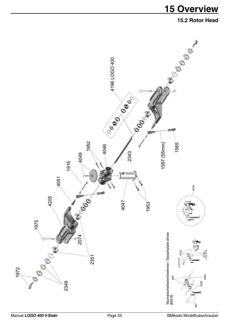
15 Overview 15.2 Rotor Head
Manual LOGO 400 V-Stabi Page 34 ©Mikado Modellhubschrauber
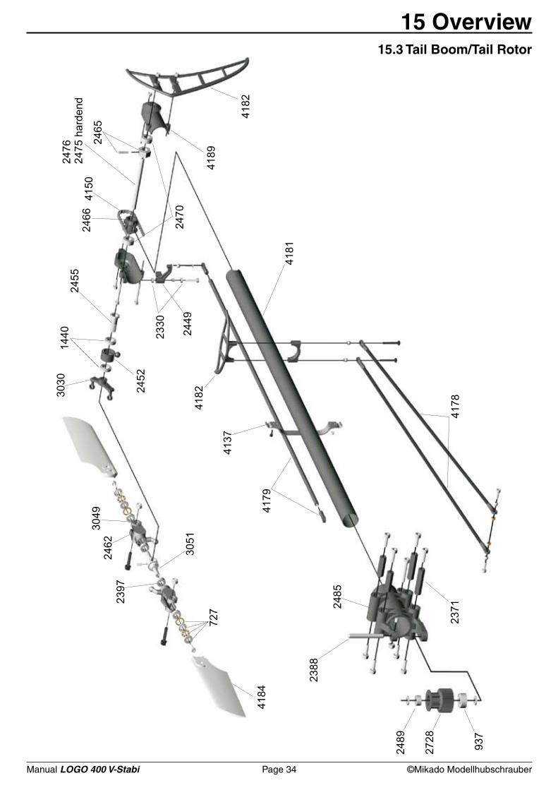
15 Overview 15.3 Tail Boom/Tail Rotor
Manual LOGO 400 Page 35 ©Mikado Modellhubschrauber
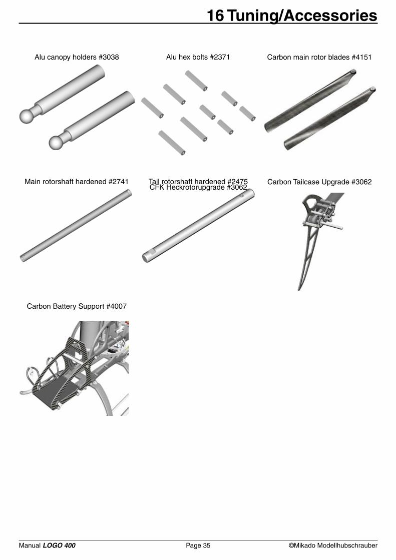
16 Tuning/Accessories
Alu canopy holders #3038
Main rotorshaft hardened #2741 Tail rotorshaft hardened #2475 Carbon Tailcase Upgrade #3062
Carbon Battery Support #4007
Carbon main rotor blades #4151Alu hex bolts #2371
CFK Heckrotorupgrade #3062

Construction & Rendering: Mehran Mahinpour Tirooni • Layout & Realisation: CDT-Berlin
www.mikado-heli.de


![Openccess. Das Angebot der Stabi...Open Access. Das Angebot der Stabi . Vortrag im Rahmen der Open -Access-Woche 2018 Openness Offenheit [ist] eine Kultur, die aus offenen Inhalten,](https://img.pdfslide.net/doc/110x75/5f7162d0e7ff1e0f1c12cbeb/openccess-das-angebot-der-stabi-open-access-das-angebot-der-stabi-vortrag.jpg)