Embed Size (px)
Citation preview

Edition06/2015
Additional Module900–010
LOGO! Logic Module | Startup 0BA8
SCE Training Curriculum
siemens.com/sce
Umschlag SCE_LOGO.indd 1Umschlag SCE_LOGO.indd 1 07.07.2015 13:56:5507.07.2015 13:56:55
© Siemens AG 2015
A new design, new hardware, new software: The perfectintelligent logic module for switching and control tasks insmall-scale automation projects has launched the nextgeneration! With LOGO! 8, it is even faster, easier, andmore convenient to implement automation solutions forsimple machines or systems, in building automation, andfor applications in the private sector. This new LOGO! gen-eration accommodates virtually every demand of custom-ers with simplified handling. Impressive features include:• Innovative LOGO! display: twice as many characters per
message for clear formulation of message texts andwith selectable backlighting, such as red, to opticallyemphasize the current alarm status
siemens.com/logo
• Integrated Ethernet interface for the entire LOGO! 8product family: communication and networking areeasier than ever before
• Remote communication via cellular phone network:text message communications for easy alerts andremote control
• New external text display: more than twice as manycharacters as before and more options thanks to twoEthernet interfaces
• New backward-compatible software in a new design:ingeniously simple operation, configuration, and pro-gramming in single and network mode
LOGO! 8 Simply ingenious. Simply more.The logic module
Answers for industry.
© Siemens AG 2015

LOGO! Logic ModuleSCE Training Curriculum
Additional Module 900-010
Edition 06/2015
© Siemens AG 2015
Additional Module 900-010LOGO! Startup 0BA0-0BA8
© Siemens AG 2015
SCE Training Curriculum | Additional Module 900-010, Edition 06/2015 | Digital Factory, DF FA
2 Unrestricted for use by Education / R & D Facilities. © Siemens AG 2015. All Rights Reserved.
Suitable SCE Trainer Packages for this Training Curriculum LOGO! Controllers • LOGO! 8 12/24V ETHERNET – set of 6
Order no: 6ED1057-3SA20-0YA1 • LOGO! 8 230V ETHERNET – set of 6
Order no: 6ED1057-3SA20-0YB1 • LOGO! 0AB6 12/24V – set of 5
Order no: 6ED1057-3SA00-0YA1 • LOGO! 0AB6 230V – set of 5
Order no: 6ED1057-3SA00-0YB1 • LOGO! 0AB6 PC cable – set of 4
Order no: 6ED1057-3SA00-0YC0
LOGO! HMI • SIMATIC Basic Panel KTP 400 for LOGO! Ethernet (-0AB7) – set of 6
Order no: 6AV2123-2DB03-0AA0 • SIMATIC Basic Panel KTP 400 for LOGO! Ethernet (-0AB7) – set of 1
Order no: 6AV2123-2DB03-0AA1 Please note that these training packages are replaced with successor packages when necessary. An overview of the currently available SCE trainer packages is provided under: siemens.com/sce/tp Supplementary information for LOGO! Such as Web-based Training, Getting started, videos, tutorials, manuals and programming guidelines. siemens.com/sce/logo Advanced Training For regional Siemens SCE advanced training courses, please get in touch with your regional SCE contact person. siemens.com/sce/contact Additional information regarding SCE siemens.com/sce Information regarding usage This SCE training curriculum for the end-to-end automation solution was prepared for the program "Siemens Automation Cooperates with Education (SCE)" specifically for training purposes for public educational facilities and R&D facilities. Siemens AG does not guarantee the contents. This document is to be used only for initial training on Siemens products/systems, which means it can be copied entirely or partially and given to those being trained to use within the scope of their training. Distributing or copying this training curriculum and sharing its contents is permitted within public training and advanced training facilities for training purposes. Exceptions require written permission from the Siemens AG contact person: Roland Scheuerer [email protected]. Infringements will require compensation for damages. All rights, including to the translation, are reserved, particularly if a patent is granted or a utility model or design is registered. Use for industrial customer courses is expressly prohibited. We do not consent to the training curriculums being used commercially. We wish to thank the Michael Dziallas Engineering Corporation and all other involved persons for their support during the preparation of this training curriculum.
© Siemens AG 2015
SCE Training Curriculum | Additional Module 900-010, Edition 06/2015 | Digital Factory, DF FA
Unrestricted for use by Education / R & D Facilities. © Siemens AG 2015. All Rights Reserved. 3
Content
Page: 1. Preface ............................................................................................................................................................ 4 2. Notes on use of LOGO! logic modules ........................................................................................................ 6 3. First steps with LOGO! 0BA0 – 0BA6 .......................................................................................................... 7
3.1 Connectors ............................................................................................................................................... 7 3.2 LOGO! connectors ................................................................................................................................... 7 3.3 LOGO! knows the following connectors ................................................................................................... 8 3.4 Blocks and block numbers ....................................................................................................................... 8 3.5 Blocks ....................................................................................................................................................... 8 3.6 Logical operations .................................................................................................................................... 8 3.7 Display of blocks in LOGO! display .......................................................................................................... 9 3.8 Assignment of a block number ................................................................................................................. 9 3.9 The 4 golden rules of LOGO! operation ................................................................................................. 10 3.10 Overview of LOGO! menus .................................................................................................................... 11
4. Example task: Plant gate control with LOGO! 0BA0 – 0BA6 .................................................................. 12 4.1 Requirements on the gate control .......................................................................................................... 12 4.2 Wiring the gate control with LOGO! 12/24RC ........................................................................................ 13 4.3 Used LOGO! components and connectors ............................................................................................ 13 4.4 Function block diagram of LOGO! solution ............................................................................................ 14
5. Program input into LOGO! 0BA0 – 0BA6 .................................................................................................. 15 5.1 Changing to "Programming" mode ........................................................................................................ 15 5.2 LOGO! changes to the programming menu ........................................................................................... 15 5.3 Entering the program ............................................................................................................................. 16 5.4 Parameter assignment of a block .......................................................................................................... 17 5.5 Switch LOGO! to RUN ........................................................................................................................... 20
6. LOGO! software for LOGO! 0BA0 – 0BA8 ................................................................................................. 22 6.1 LOGO!Soft Comfort ................................................................................................................................ 22 6.2 Connecting LOGO! with a PC ................................................................................................................ 23
7. Commissioning a LOGO! 0BA7 with LOGO!Soft Comfort V7.1 .............................................................. 27 7.1 Setting the IP address of LOGO! 0BA7 ................................................................................................. 27 7.2 Creating the circuit program ................................................................................................................... 31 7.3 Simulation of the circuit .......................................................................................................................... 39 7.4 Online test .............................................................................................................................................. 41
8. Commissioning a LOGO! 0BA8 with LOGO!Soft Comfort V8.0 .............................................................. 42 8.1 Setting the IP address on LOGO! 0BA8 ................................................................................................ 42 8.2 LOGO!Soft Comfort V8.0 ....................................................................................................................... 42 8.3 User interface of LOGO!Soft Comfort V8.0 ............................................................................................ 43
9. PROJECT PLANT GATE CONTROL WITH LOGO!SOFT COMFORT V8.0 AND LOGO! 0BA8 .............. 45 9.1 Starting LOGO!Soft Comfort V8.0 and adding LOGO! 0BA8 ................................................................ 45 9.2 LOGO! 0BA8 settings ............................................................................................................................. 47 9.3 Entering input/output names .................................................................................................................. 49 9.4 Entering a program in the Diagram Editor ............................................................................................. 50 9.5 Simulation of the circuit .......................................................................................................................... 57 9.6 Transferring the tested program to LOGO! ............................................................................................ 59 9.7 Online test .............................................................................................................................................. 60
10. Additional information .................................................................................................................................. 60
© Siemens AG 2015
SCE Training Curriculum | Additional Module 900-010, Edition 06/2015 | Digital Factory, DF FA
4 Unrestricted for use by Education / R & D Facilities. © Siemens AG 2015. All Rights Reserved.
1. PREFACE The contents of the module SCE_EN_900-010 are associated with the training unit basics of LOGO! programming and represent a Quick Start to the handling of LOGO! logic modules 0BA3 to 0BA7 and programming with the LOGO!Soft Comfort software. Training Objective: The reader is to learn about the main functions of the LOGO! logic module in this module. Typical tasks are explained by using a sample task and processed in a project in the following steps:
Creating a program for the LOGO! logic module
Testing the task in LOGO! RUN mode
Setting the IP address
Setting the interface with the LOGO! software
Programming the task with the LOGO! software
Simulating the task with the LOGO! software
Online test of the task with the LOGO! software
Basics of LOGOProgramming Module 900
© Siemens AG 2015
SCE Training Curriculum | Additional Module 900-010, Edition 06/2015 | Digital Factory, DF FA
Unrestricted for use by Education / R & D Facilities. © Siemens AG 2015. All Rights Reserved. 5
Requirements:
To successfully work through this module, the following knowledge is assumed:
Proficiency in working with Windows
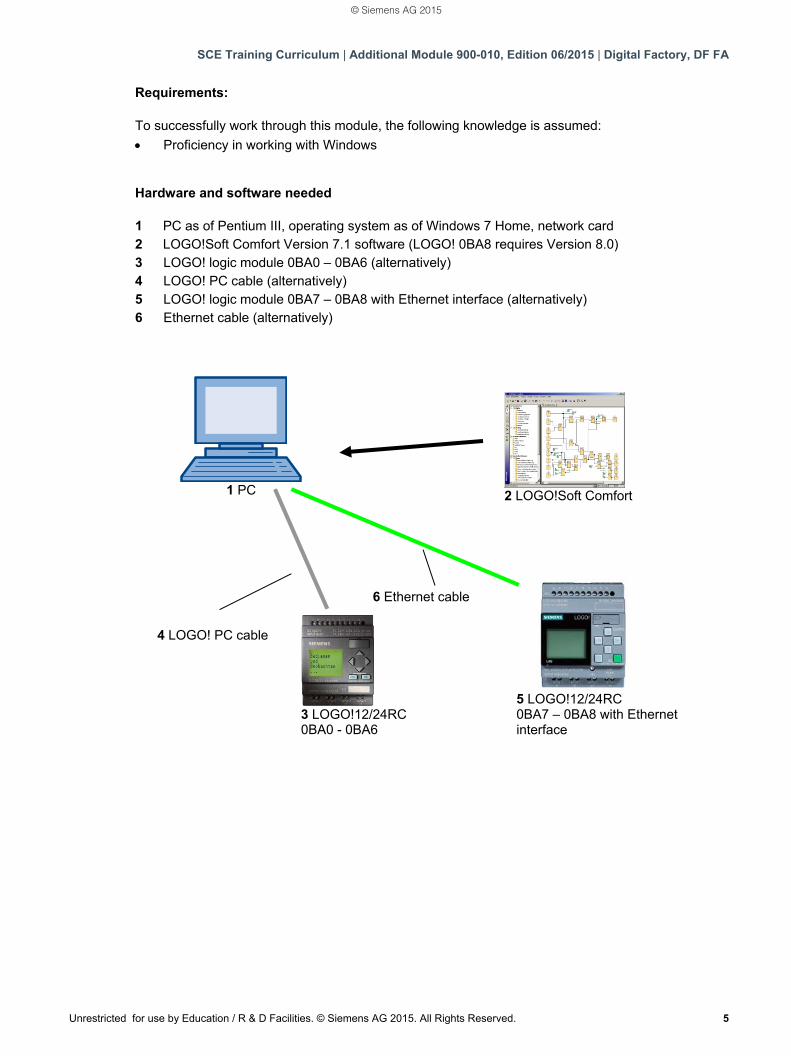
Hardware and software needed
1 PC as of Pentium III, operating system as of Windows 7 Home, network card 2 LOGO!Soft Comfort Version 7.1 software (LOGO! 0BA8 requires Version 8.0) 3 LOGO! logic module 0BA0 – 0BA6 (alternatively) 4 LOGO! PC cable (alternatively) 5 LOGO! logic module 0BA7 – 0BA8 with Ethernet interface (alternatively) 6 Ethernet cable (alternatively)
3 LOGO!12/24RC 0BA0 - 0BA6
2 LOGO!Soft Comfort
1 PC
4 LOGO! PC cable
5 LOGO!12/24RC 0BA7 – 0BA8 with Ethernet interface
6 Ethernet cable
© Siemens AG 2015
SCE Training Curriculum | Additional Module 900-010, Edition 06/2015 | Digital Factory, DF FA
6 Unrestricted for use by Education / R & D Facilities. © Siemens AG 2015. All Rights Reserved.
2. NOTES ON USE OF LOGO! LOGIC MODULES LOGO! is the universal logic module from Siemens. LOGO! integrates the controller with operator control and display unit. You can use the LOGO! operator control and display unit to create programs, edit and execute system functions. You can use an interface or a PC cable from the LOGO! SOFT programming software to read in an external program from a program module. In addition to creating a program, you can use LOGO! SOFT to simulate your circuit on the computer or print out overview diagrams. Depending on the device type, the LOGO! logic modules already include ready-to-use basic functions, such as delayed ON, delayed OFF and current impulse relay, time switch, binary bit memory, as well as inputs and outputs. You solve tasks with LOGO!: - in home and installation technology (e.g. stairway lighting, outside lighting, awnings, shutters,
show window lighting and much more), - in control cabinet installation and machine and apparatus design (e.g. gate controls, ventilation
systems, industrial water pumps and much more). LOGO! can also be used for special controllers for signal pre-processing. By connecting the LOGO! module to the AS–Interface, it can be used as I/O with its own intelligence to control machines and processes on-site. This means you can execute control tasks in the LOGO! logic module and reduce the load on the master controller by doing so. There are special versions without operating unit for serial applications in small machine and apparatus engineering, in control cabinet installation and the installation area. These must be downloaded afterwards by means of a program module or with the LOGO! SOFT PC software.
© Siemens AG 2015
SCE Training Curriculum | Additional Module 900-010, Edition 06/2015 | Digital Factory, DF FA
Unrestricted for use by Education / R & D Facilities. © Siemens AG 2015. All Rights Reserved. 7
3. FIRST STEPS WITH LOGO! 0BA0 – 0BA6 Programming is defined as entering a circuit. A LOGO! program is actually nothing more than a circuit diagram in a somewhat different layout. We have adapted the display to match the LOGO! display panel. In this chapter we will show you how to use LOGO! to turn your applications into LOGO! programs. We start out by introducing you to the two basic terms Connector and Block and show you what they mean. In a second step we will show you how to develop a program from a simple conventional circuit which you can enter directly into LOGO! in the third step. After working through only a few pages of the manual, your first program will be saved and ready to run in LOGO!. You will be able to conduct your first tests with the matching hardware (switches...).
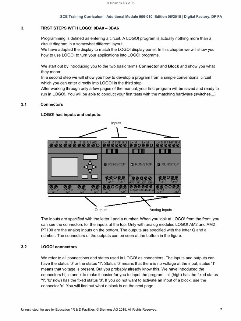
3.1 Connectors LOGO! has inputs and outputs:
The inputs are specified with the letter I and a number. When you look at LOGO! from the front, you can see the connectors for the inputs at the top. Only with analog modules LOGO! AM2 and AM2 PT100 are the analog inputs on the bottom. The outputs are specified with the letter Q and a number. The connectors of the outputs can be seen at the bottom in the figure.
3.2 LOGO! connectors
We refer to all connections and states used in LOGO! as connectors. The inputs and outputs can have the status '0' or the status '1'. Status '0' means that there is no voltage at the input; status '1' means that voltage is present. But you probably already know this. We have introduced the connectors hi, lo and x to make it easier for you to input the program. 'hi' (high) has the fixed status '1'. 'lo' (low) has the fixed status '0'. If you do not want to activate an input of a block, use the connector 'x'. You will find out what a block is on the next page.
Inputs
Outputs Analog Inputs
© Siemens AG 2015
SCE Training Curriculum | Additional Module 900-010, Edition 06/2015 | Digital Factory, DF FA
8 Unrestricted for use by Education / R & D Facilities. © Siemens AG 2015. All Rights Reserved.
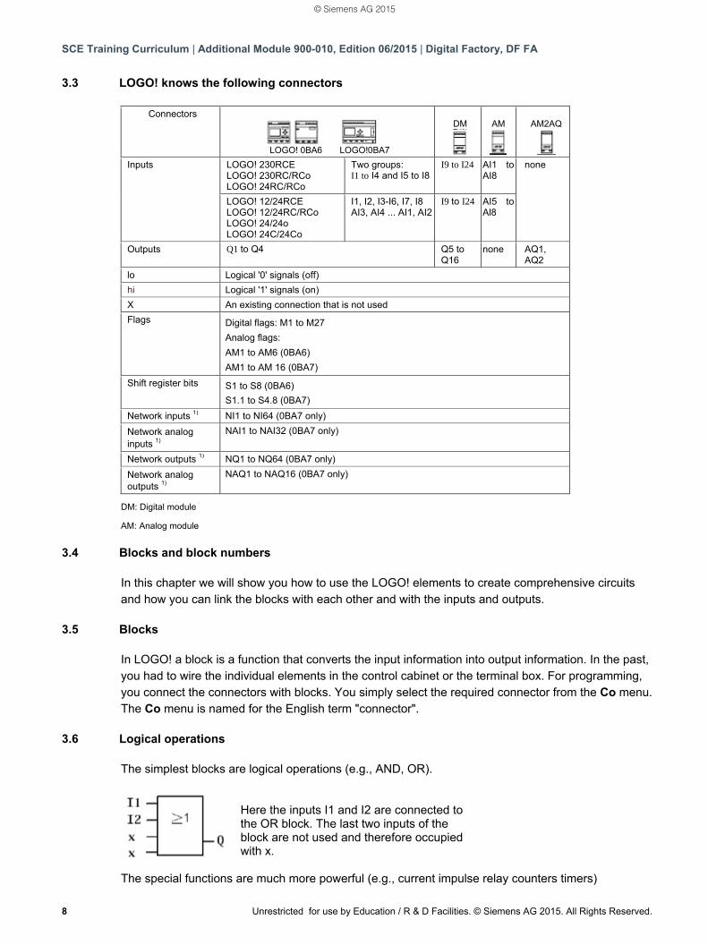
3.3 LOGO! knows the following connectors
Connectors
LOGO! 0BA6 LOGO!0BA7
DM AM AM2AQ
Inputs LOGO! 230RCE
LOGO! 230RC/RCo LOGO! 24RC/RCo
Two groups: I1 to I4 and I5 to I8
I9 to I24 AI1 to AI8
none
LOGO! 12/24RCE LOGO! 12/24RC/RCo LOGO! 24/24o LOGO! 24C/24Co
I1, I2, I3-I6, I7, I8 AI3, AI4 ... AI1, AI2
I9 to I24 AI5 to Al8
Outputs Q1 to Q4 Q5 to Q16
none AQ1, AQ2
lo Logical '0' signals (off)
hi Logical '1' signals (on)
X An existing connection that is not used
Flags Digital flags: M1 to M27
Analog flags:
AM1 to AM6 (0BA6)
AM1 to AM 16 (0BA7)
Shift register bits S1 to S8 (0BA6)
S1.1 to S4.8 (0BA7)
Network inputs 1) NI1 to NI64 (0BA7 only)
Network analog inputs 1)
NAI1 to NAI32 (0BA7 only)
Network outputs 1) NQ1 to NQ64 (0BA7 only)
Network analog outputs 1)
NAQ1 to NAQ16 (0BA7 only)
DM: Digital module
AM: Analog module
3.4 Blocks and block numbers In this chapter we will show you how to use the LOGO! elements to create comprehensive circuits and how you can link the blocks with each other and with the inputs and outputs.
3.5 Blocks In LOGO! a block is a function that converts the input information into output information. In the past, you had to wire the individual elements in the control cabinet or the terminal box. For programming, you connect the connectors with blocks. You simply select the required connector from the Co menu. The Co menu is named for the English term "connector".
3.6 Logical operations The simplest blocks are logical operations (e.g., AND, OR).
Here the inputs I1 and I2 are connected to the OR block. The last two inputs of the block are not used and therefore occupied with x.
The special functions are much more powerful (e.g., current impulse relay counters timers)
© Siemens AG 2015
SCE Training Curriculum | Additional Module 900-010, Edition 06/2015 | Digital Factory, DF FA
Unrestricted for use by Education / R & D Facilities. © Siemens AG 2015. All Rights Reserved. 9
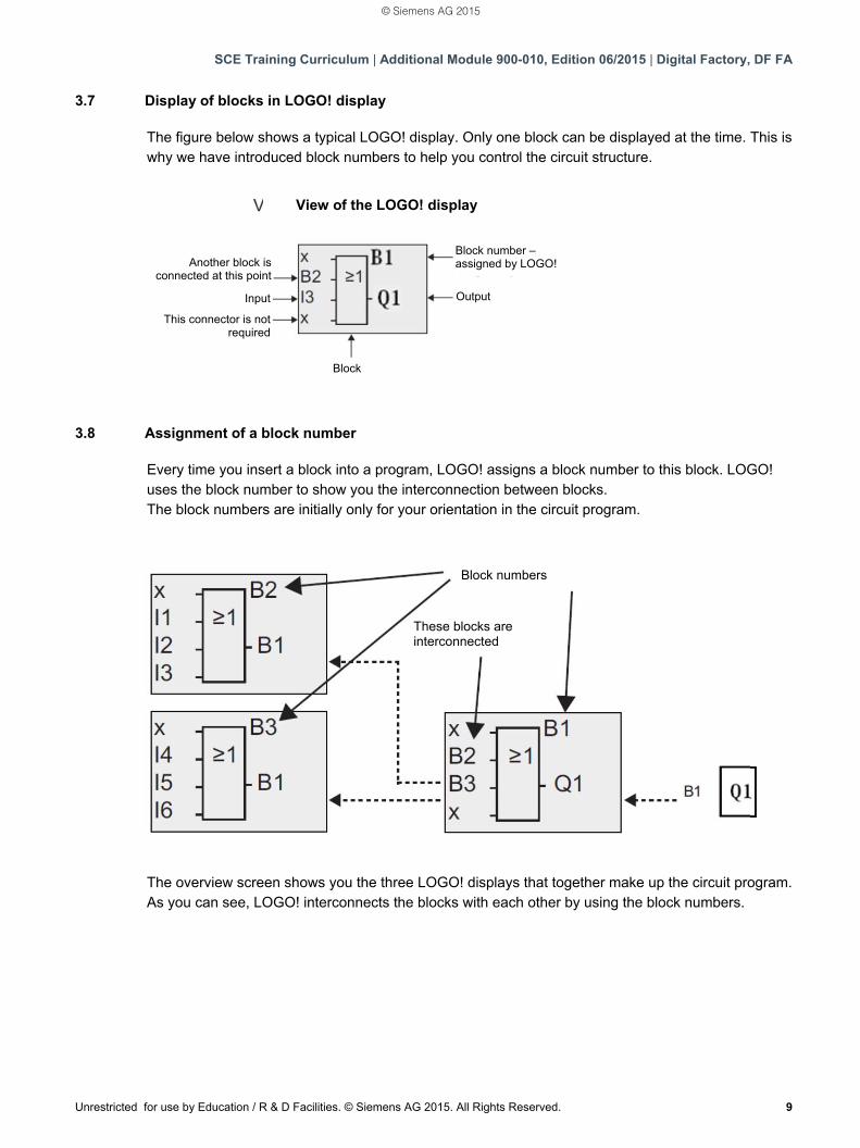
3.7 Display of blocks in LOGO! display The figure below shows a typical LOGO! display. Only one block can be displayed at the time. This is why we have introduced block numbers to help you control the circuit structure.
3.8 Assignment of a block number Every time you insert a block into a program, LOGO! assigns a block number to this block. LOGO! uses the block number to show you the interconnection between blocks. The block numbers are initially only for your orientation in the circuit program.
The overview screen shows you the three LOGO! displays that together make up the circuit program. As you can see, LOGO! interconnects the blocks with each other by using the block numbers.
View of the LOGO! display
Another block is connected at this point
This connector is not required
Input
Block
Block number – assigned by LOGO!
Output
Block numbers
These blocks are interconnected
© Siemens AG 2015
SCE Training Curriculum | Additional Module 900-010, Edition 06/2015 | Digital Factory, DF FA
10 Unrestricted for use by Education / R & D Facilities. © Siemens AG 2015. All Rights Reserved.
3.9 The 4 golden rules of LOGO! operation Rule 1 - Changing the operating mode You create the circuit program in the Programming mode. After a Power on and "No Program / Press ESC" on the display, you press ESC to enter Programming mode. You can change the time values and parameter values of an existing circuit program in the Parameter assignment and Programming modes. LOGO! is in RUN mode during parameter assignment, which means the circuit program is still being processed. You must stop the processing of the circuit program for programming with the "Stop" command. You get to RUN mode with the menu item 'Start' in the main menu. Press ESC in RUN mode to return to the Parameter assignment mode. If you are in Parameter assignment mode and want to return to Programming mode, run the "Stop" command in the parameter assignment menu and answer with "Yes" for "Stop Prg" by moving the cursor to "Yes" and pressing OK.
Rule 2 - Outputs and inputs You always enter a circuit from the output to the input. You can connect an output with several inputs but not connect several outputs to one input. You cannot connect an output with a preceding input within a program path. You need to interconnect bit memories or outputs for such internal feedback. Rule 3 - Cursor and cursor movement The following applies when entering a circuit: You can move the cursor when it is shown as underscore. – you move the cursor in the circuit with the , , or keys – you change to "Select connector/block" with OK – you exit entering the circuit with ESC If the cursor is displayed as solid block, you must select a connector/block. – you select a connector/block with the or keys – you apply the selection with OK – you go back one step with ESC Rule 4 – Planning Before you enter a circuit, you plan it completely on paper or program LOGO! directly with LOGO!Soft or LOGO!Soft Comfort. LOGO! can only save complete programs. If a circuit has not been entered completely, LOGO! cannot exit the Programming mode.
© Siemens AG 2015
SCE Training Curriculum | Additional Module 900-010, Edition 06/2015 | Digital Factory, DF FA
Unrestricted for use by Education / R & D Facilities. © Siemens AG 2015. All Rights Reserved. 11
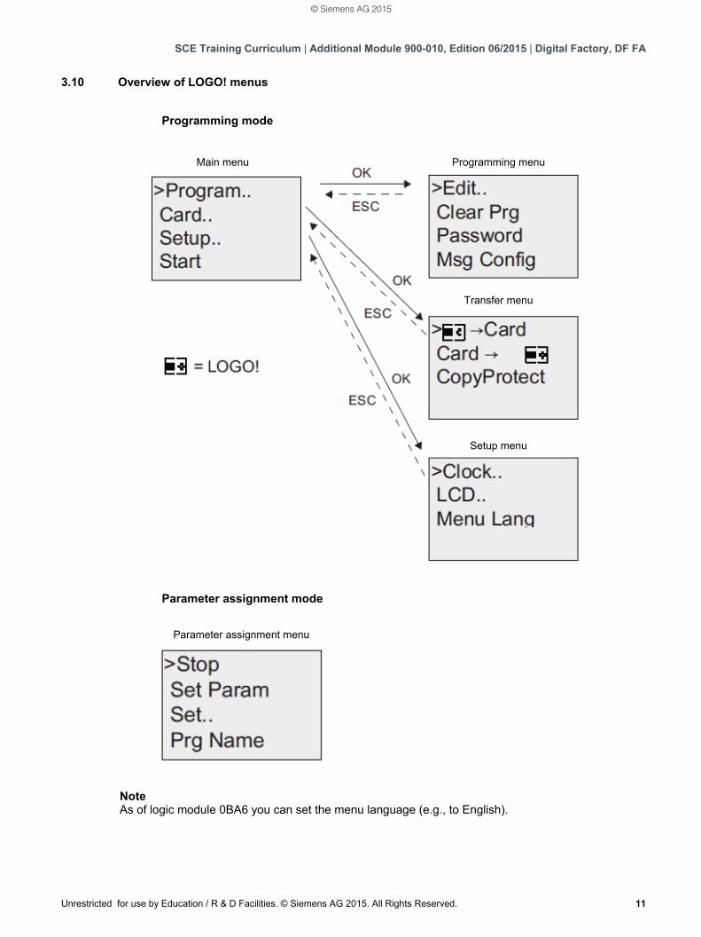
3.10 Overview of LOGO! menus
Note As of logic module 0BA6 you can set the menu language (e.g., to English).
Programming mode
Parameter assignment mode
Main menu Programming menu
Transfer menu
Setup menu
Parameter assignment menu
© Siemens AG 2015
SCE Training Curriculum | Additional Module 900-010, Edition 06/2015 | Digital Factory, DF FA
12 Unrestricted for use by Education / R & D Facilities. © Siemens AG 2015. All Rights Reserved.
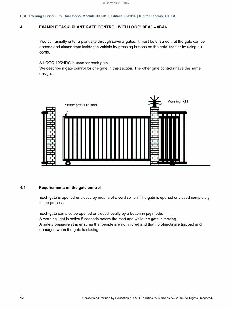
4. EXAMPLE TASK: PLANT GATE CONTROL WITH LOGO! 0BA0 – 0BA6 You can usually enter a plant site through several gates. It must be ensured that the gate can be opened and closed from inside the vehicle by pressing buttons on the gate itself or by using pull cords. A LOGO!12/24RC is used for each gate. We describe a gate control for one gate in this section. The other gate controls have the same design.
4.1 Requirements on the gate control Each gate is opened or closed by means of a cord switch. The gate is opened or closed completely in the process. Each gate can also be opened or closed locally by a button in jog mode. A warning light is active 5 seconds before the start and while the gate is moving. A safety pressure strip ensures that people are not injured and that no objects are trapped and damaged when the gate is closing.
Safety pressure strip Warning light
© Siemens AG 2015
SCE Training Curriculum | Additional Module 900-010, Edition 06/2015 | Digital Factory, DF FA
Unrestricted for use by Education / R & D Facilities. © Siemens AG 2015. All Rights Reserved. 13
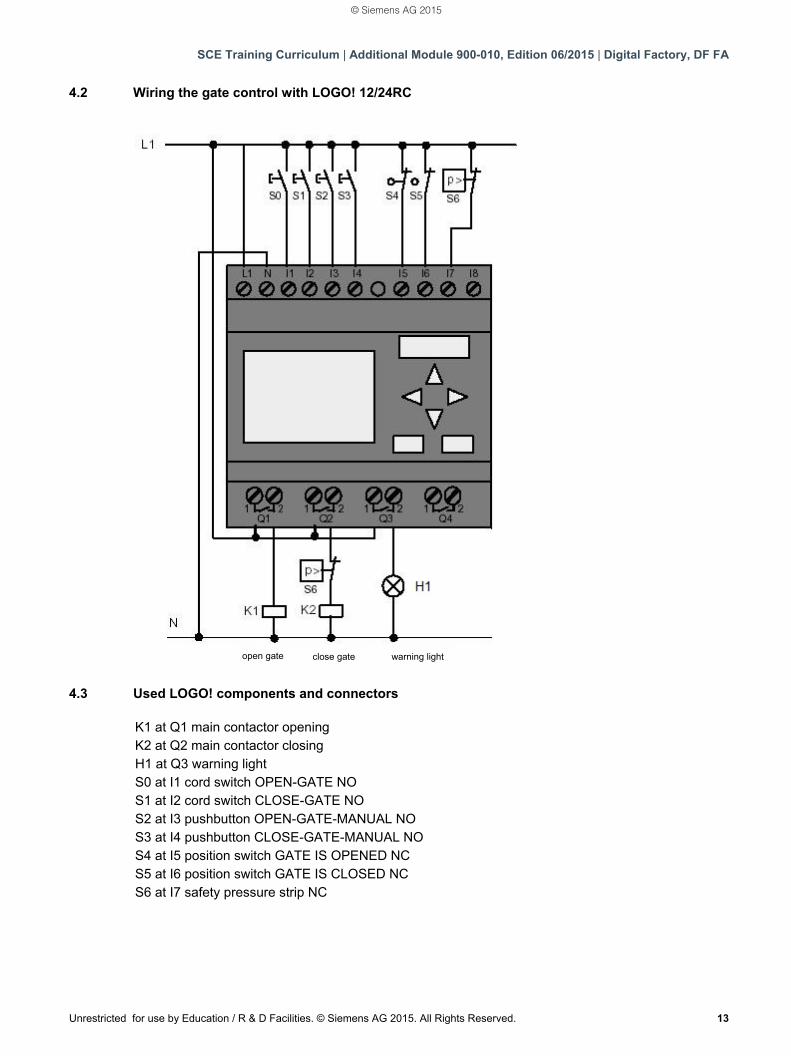
4.2 Wiring the gate control with LOGO! 12/24RC
4.3 Used LOGO! components and connectors K1 at Q1 main contactor opening K2 at Q2 main contactor closing H1 at Q3 warning light S0 at I1 cord switch OPEN-GATE NO S1 at I2 cord switch CLOSE-GATE NO S2 at I3 pushbutton OPEN-GATE-MANUAL NO S3 at I4 pushbutton CLOSE-GATE-MANUAL NO S4 at I5 position switch GATE IS OPENED NC S5 at I6 position switch GATE IS CLOSED NC S6 at I7 safety pressure strip NC
open gate close gate warning light
© Siemens AG 2015
SCE Training Curriculum | Additional Module 900-010, Edition 06/2015 | Digital Factory, DF FA
14 Unrestricted for use by Education / R & D Facilities. © Siemens AG 2015. All Rights Reserved.
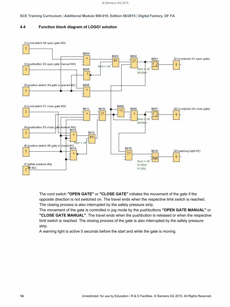
4.4 Function block diagram of LOGO! solution
The cord switch "OPEN GATE" or "CLOSE GATE" initiates the movement of the gate if the opposite direction is not switched on. The travel ends when the respective limit switch is reached. The closing process is also interrupted by the safety pressure strip. The movement of the gate is controlled in jog mode by the pushbuttons "OPEN GATE MANUAL" or "CLOSE GATE MANUAL". The travel ends when the pushbutton is released or when the respective limit switch is reached. The closing process of the gate is also interrupted by the safety pressure strip. A warning light is active 5 seconds before the start and while the gate is moving.
© Siemens AG 2015
SCE Training Curriculum | Additional Module 900-010, Edition 06/2015 | Digital Factory, DF FA
Unrestricted for use by Education / R & D Facilities. © Siemens AG 2015. All Rights Reserved. 15
5. PROGRAM INPUT INTO LOGO! 0BA0 – 0BA6 You have designed a circuit and now you would like to enter it in LOGO!. We use a program input to show you to do just that.
5.1 Changing to "Programming" mode
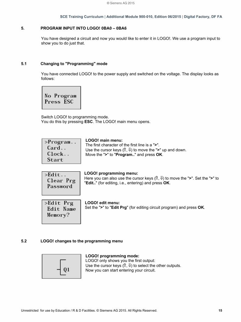
You have connected LOGO! to the power supply and switched on the voltage. The display looks as follows:
Switch LOGO! to programming mode. You do this by pressing ESC. The LOGO! main menu opens.
LOGO! main menu: The first character of the first line is a ">". Use the cursor keys (, ) to move the ">" up and down.
Move the ">" to "Program.." and press OK.
LOGO! programming menu: Here you can also use the cursor keys (, ) to move the ">". Set the ">" to "Edit.." (for editing, i.e., entering) and press OK.
LOGO! edit menu: Set the ">" to "Edit Prg" (for editing circuit program) and press OK.
5.2 LOGO! changes to the programming menu
LOGO! programming mode: LOGO! only shows you the first output: Use the cursor keys (, ) to select the other outputs.
Now you can start entering your circuit.
© Siemens AG 2015
SCE Training Curriculum | Additional Module 900-010, Edition 06/2015 | Digital Factory, DF FA
16 Unrestricted for use by Education / R & D Facilities. © Siemens AG 2015. All Rights Reserved.
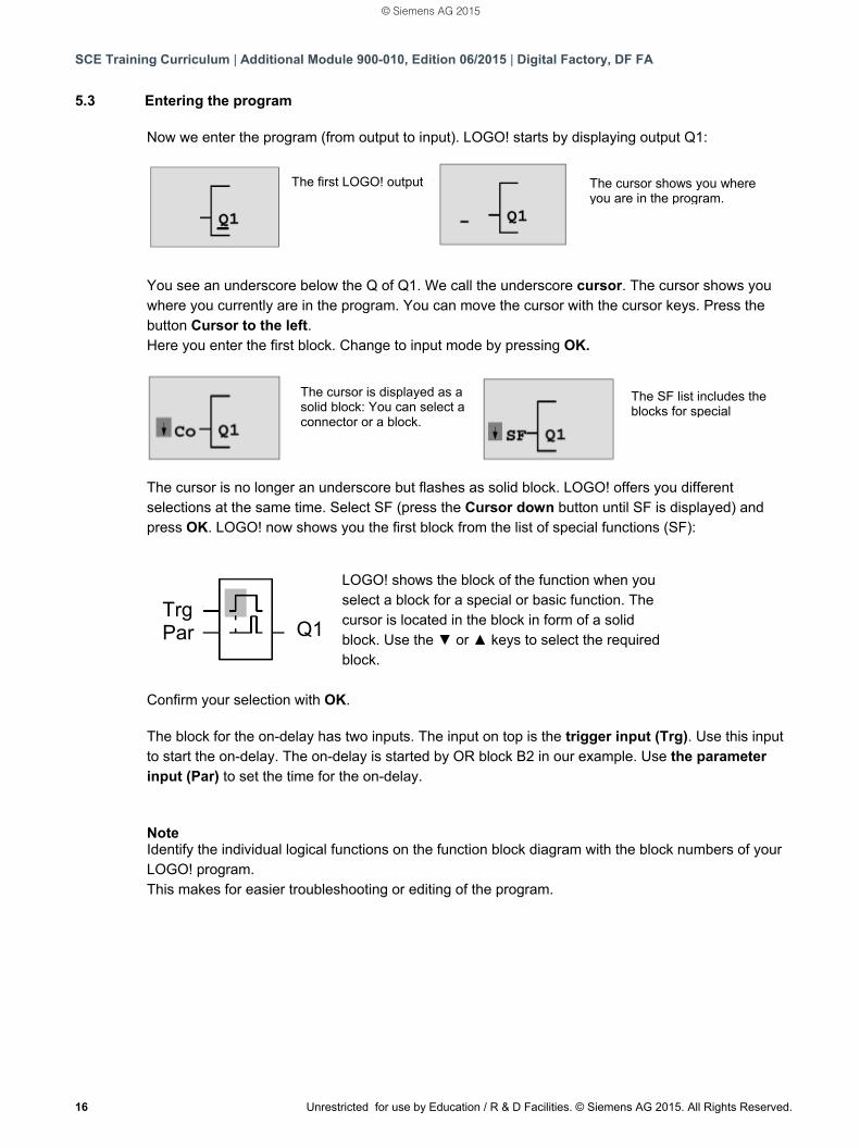
5.3 Entering the program Now we enter the program (from output to input). LOGO! starts by displaying output Q1:
You see an underscore below the Q of Q1. We call the underscore cursor. The cursor shows you where you currently are in the program. You can move the cursor with the cursor keys. Press the button Cursor to the left. Here you enter the first block. Change to input mode by pressing OK.
The cursor is no longer an underscore but flashes as solid block. LOGO! offers you different selections at the same time. Select SF (press the Cursor down button until SF is displayed) and press OK. LOGO! now shows you the first block from the list of special functions (SF):
Confirm your selection with OK. The block for the on-delay has two inputs. The input on top is the trigger input (Trg). Use this input to start the on-delay. The on-delay is started by OR block B2 in our example. Use the parameter input (Par) to set the time for the on-delay. Note Identify the individual logical functions on the function block diagram with the block numbers of your LOGO! program. This makes for easier troubleshooting or editing of the program.
The first LOGO! output The cursor shows you where you are in the program.
The cursor is displayed as a solid block: You can select a connector or a block.
The SF list includes the blocks for special
LOGO! shows the block of the function when you select a block for a special or basic function. The cursor is located in the block in form of a solid block. Use the ▼ or ▲ keys to select the required block.
Trg Par Q1
© Siemens AG 2015
SCE Training Curriculum | Additional Module 900-010, Edition 06/2015 | Digital Factory, DF FA
Unrestricted for use by Education / R & D Facilities. © Siemens AG 2015. All Rights Reserved. 17
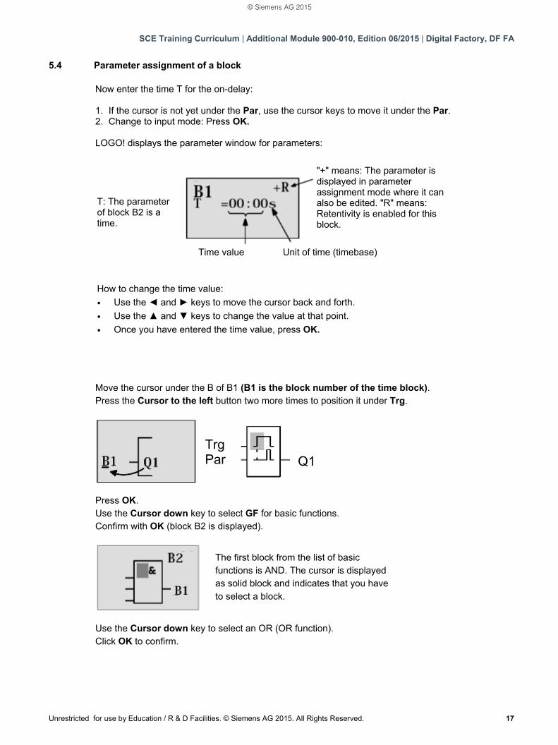
5.4 Parameter assignment of a block Now enter the time T for the on-delay: 1. If the cursor is not yet under the Par, use the cursor keys to move it under the Par. 2. Change to input mode: Press OK. LOGO! displays the parameter window for parameters:
Move the cursor under the B of B1 (B1 is the block number of the time block). Press the Cursor to the left button two more times to position it under Trg.
Press OK. Use the Cursor down key to select GF for basic functions. Confirm with OK (block B2 is displayed).
Use the Cursor down key to select an OR (OR function). Click OK to confirm.
T: The parameter of block B2 is a time.
Time value Unit of time (timebase)
"+" means: The parameter is displayed in parameter assignment mode where it can also be edited. "R" means: Retentivity is enabled for this block.
How to change the time value:
Use the ◄ and ► keys to move the cursor back and forth.
Use the ▲ and ▼ keys to change the value at that point.
Once you have entered the time value, press OK.
Trg Par Q1
The first block from the list of basic functions is AND. The cursor is displayed as solid block and indicates that you have to select a block.
© Siemens AG 2015
SCE Training Curriculum | Additional Module 900-010, Edition 06/2015 | Digital Factory, DF FA
18 Unrestricted for use by Education / R & D Facilities. © Siemens AG 2015. All Rights Reserved.
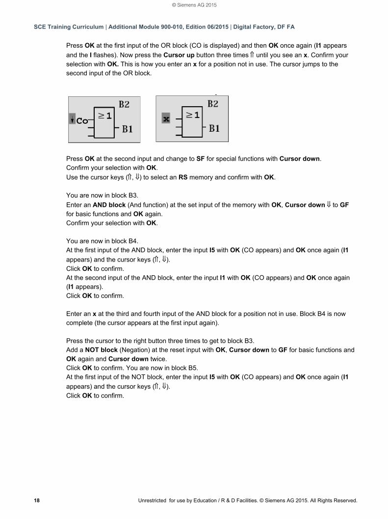
Press OK at the first input of the OR block (CO is displayed) and then OK once again (I1 appears
and the I flashes). Now press the Cursor up button three times until you see an x. Confirm your selection with OK. This is how you enter an x for a position not in use. The cursor jumps to the second input of the OR block.
Press OK at the second input and change to SF for special functions with Cursor down. Confirm your selection with OK.
Use the cursor keys (, ) to select an RS memory and confirm with OK. You are now in block B3.
Enter an AND block (And function) at the set input of the memory with OK, Cursor down to GF for basic functions and OK again. Confirm your selection with OK. You are now in block B4. At the first input of the AND block, enter the input I5 with OK (CO appears) and OK once again (I1
appears) and the cursor keys (, ). Click OK to confirm. At the second input of the AND block, enter the input I1 with OK (CO appears) and OK once again (I1 appears). Click OK to confirm. Enter an x at the third and fourth input of the AND block for a position not in use. Block B4 is now complete (the cursor appears at the first input again). Press the cursor to the right button three times to get to block B3. Add a NOT block (Negation) at the reset input with OK, Cursor down to GF for basic functions and OK again and Cursor down twice. Click OK to confirm. You are now in block B5. At the first input of the NOT block, enter the input I5 with OK (CO appears) and OK once again (I1
appears) and the cursor keys (, ). Click OK to confirm.
© Siemens AG 2015
SCE Training Curriculum | Additional Module 900-010, Edition 06/2015 | Digital Factory, DF FA
Unrestricted for use by Education / R & D Facilities. © Siemens AG 2015. All Rights Reserved. 19
Block B5 is complete and you can now move to the Par input in block B3.
Here you can set a retentivity of the memory with OK and the cursor keys (, ). Click OK to confirm. Block B3 is complete and you can now move to the third input in block B2. Enter an AND block (And function) at the third input of the OR block with OK, Cursor down to GF for basic functions and OK again. Click OK to confirm. You are now in block B6. At the first input of the AND block, enter the input I3 with OK (CO appears) and OK once again and
the cursor keys (, ). Click OK to confirm. At the second input of the AND block, enter the input I5 with OK (CO appears) and OK once again
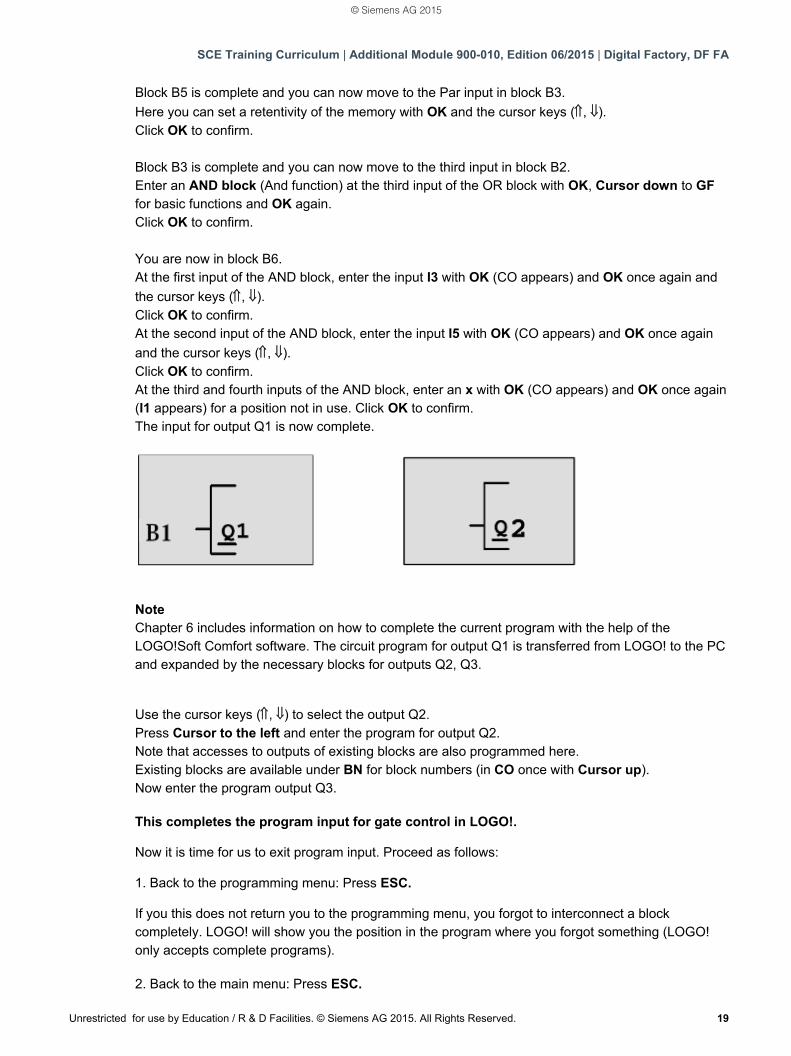
and the cursor keys (, ). Click OK to confirm. At the third and fourth inputs of the AND block, enter an x with OK (CO appears) and OK once again (I1 appears) for a position not in use. Click OK to confirm. The input for output Q1 is now complete.
Note Chapter 6 includes information on how to complete the current program with the help of the LOGO!Soft Comfort software. The circuit program for output Q1 is transferred from LOGO! to the PC and expanded by the necessary blocks for outputs Q2, Q3. Use the cursor keys (, ) to select the output Q2. Press Cursor to the left and enter the program for output Q2. Note that accesses to outputs of existing blocks are also programmed here. Existing blocks are available under BN for block numbers (in CO once with Cursor up). Now enter the program output Q3. This completes the program input for gate control in LOGO!. Now it is time for us to exit program input. Proceed as follows: 1. Back to the programming menu: Press ESC. If you this does not return you to the programming menu, you forgot to interconnect a block completely. LOGO! will show you the position in the program where you forgot something (LOGO! only accepts complete programs). 2. Back to the main menu: Press ESC.
© Siemens AG 2015
SCE Training Curriculum | Additional Module 900-010, Edition 06/2015 | Digital Factory, DF FA
20 Unrestricted for use by Education / R & D Facilities. © Siemens AG 2015. All Rights Reserved.
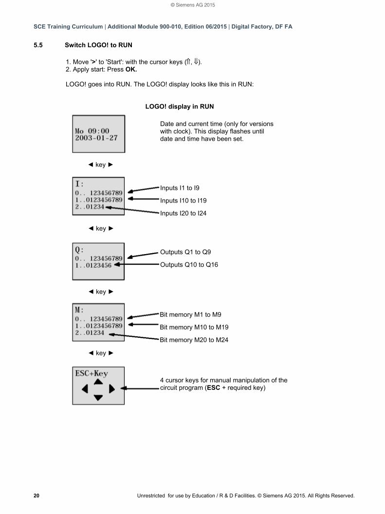
5.5 Switch LOGO! to RUN 1. Move '>' to 'Start': with the cursor keys (, ). 2. Apply start: Press OK. LOGO! goes into RUN. The LOGO! display looks like this in RUN:
4 cursor keys for manual manipulation of the circuit program (ESC + required key)
◄ key ►
◄ key ►
◄ key ►
◄ key ►
LOGO! display in RUN
Date and current time (only for versions with clock). This display flashes until date and time have been set.
Inputs I1 to I9
Inputs I10 to I19
Inputs I20 to I24
Outputs Q1 to Q9
Outputs Q10 to Q16
Bit memory M1 to M9
Bit memory M10 to M19
Bit memory M20 to M24
© Siemens AG 2015
SCE Training Curriculum | Additional Module 900-010, Edition 06/2015 | Digital Factory, DF FA
Unrestricted for use by Education / R & D Facilities. © Siemens AG 2015. All Rights Reserved. 21
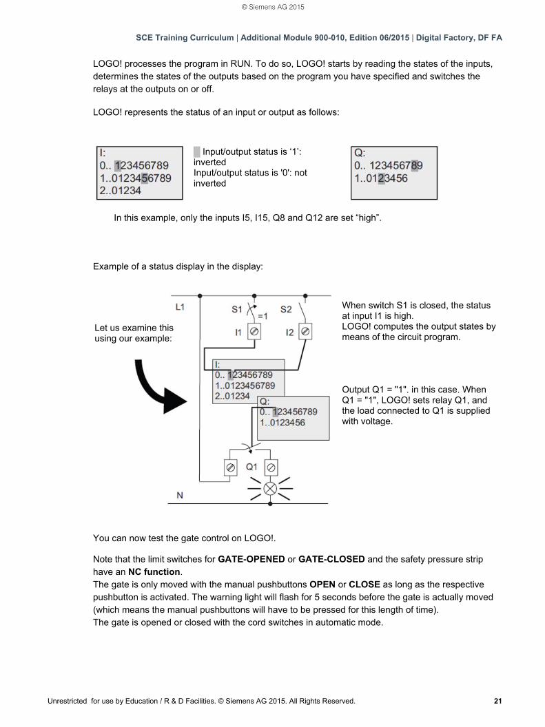
LOGO! processes the program in RUN. To do so, LOGO! starts by reading the states of the inputs, determines the states of the outputs based on the program you have specified and switches the relays at the outputs on or off. LOGO! represents the status of an input or output as follows:
Example of a status display in the display:
You can now test the gate control on LOGO!. Note that the limit switches for GATE-OPENED or GATE-CLOSED and the safety pressure strip have an NC function. The gate is only moved with the manual pushbuttons OPEN or CLOSE as long as the respective pushbutton is activated. The warning light will flash for 5 seconds before the gate is actually moved (which means the manual pushbuttons will have to be pressed for this length of time). The gate is opened or closed with the cord switches in automatic mode.
█ Input/output status is ‘1’: inverted Input/output status is '0': not inverted
In this example, only the inputs I5, I15, Q8 and Q12 are set “high”.
Let us examine this using our example:
When switch S1 is closed, the status at input I1 is high. LOGO! computes the output states by means of the circuit program. Output Q1 = "1". in this case. When Q1 = "1", LOGO! sets relay Q1, and the load connected to Q1 is supplied with voltage.
© Siemens AG 2015
SCE Training Curriculum | Additional Module 900-010, Edition 06/2015 | Digital Factory, DF FA
22 Unrestricted for use by Education / R & D Facilities. © Siemens AG 2015. All Rights Reserved.
6. LOGO! SOFTWARE FOR LOGO! 0BA0 – 0BA8
The LOGO!Soft Comfort program is available as programming package for your PC. The software
includes the following services:
- Graphical offline creation of your circuit program as ladder diagram (ladder logic / circuit
diagram) or as function block diagram (FBD)
- Simulation of your circuit program on the computer
- Generation and printing of an overview diagram of the circuit program
- Data backup of the circuit program on the hard disk or any other medium
- Comparing circuit programs
- Convenient parameter assignment of blocks
- Transfer of circuit program
from LOGO! to the PC
from the PC to LOGO!
- Reading the operation-hour counter
- Set clock
- Summer time / Winter time
- Online test: Display of states and actual values of LOGO! in RUN mode:
States of all digital inputs, digital outputs, bit memories, shift register bits and cursor keys
Values of all analog inputs, analog outputs and bit memories
All block results
Actual values (including times) of selected blocks
- Stop processing of the circuit program from the PC (STOP).
6.1 LOGO!Soft Comfort
LOGO!Soft Comfort offers an alternative to standard planning:
- You initially develop your circuit program at your desk.
- You simulate the circuit program on the computer and check the functionality even before the
circuit program is actually used.
- You can comment and print your circuit program.
- You save your circuit programs in your PC file system.
- This makes a circuit program immediately available for later changes.
- You transfer the circuit program to LOGO! by simply pushing a few buttons.
© Siemens AG 2015
SCE Training Curriculum | Additional Module 900-010, Edition 06/2015 | Digital Factory, DF FA
Unrestricted for use by Education / R & D Facilities. © Siemens AG 2015. All Rights Reserved. 23
6.2 Connecting LOGO! with a PC
Standard LOGO! 0BA0 to 0BA6
You need a LOGO! PC cable to connect a standard LOGO! with a PC.
Remove the cover cap or the program module (card) on your LOGO! and connect the cable. The
other end of the cable is connected with the serial interface or a USB port of your PC.
LOGO! 0BA7 to 0BA8 with Ethernet interface
You need a network cable to directly connect a LOGO! with Ethernet interface to a PC.
To program a LOGO! 0BA7 or 0BA8 with Ethernet interface from a PC, programming device or laptop, you need a TCP/IP connection. The IP addresses of both devices must match so that the PC and LOGO! 0BA7 can communicate with each other. First we show you how to set the IP address of the computer in Windows 7.
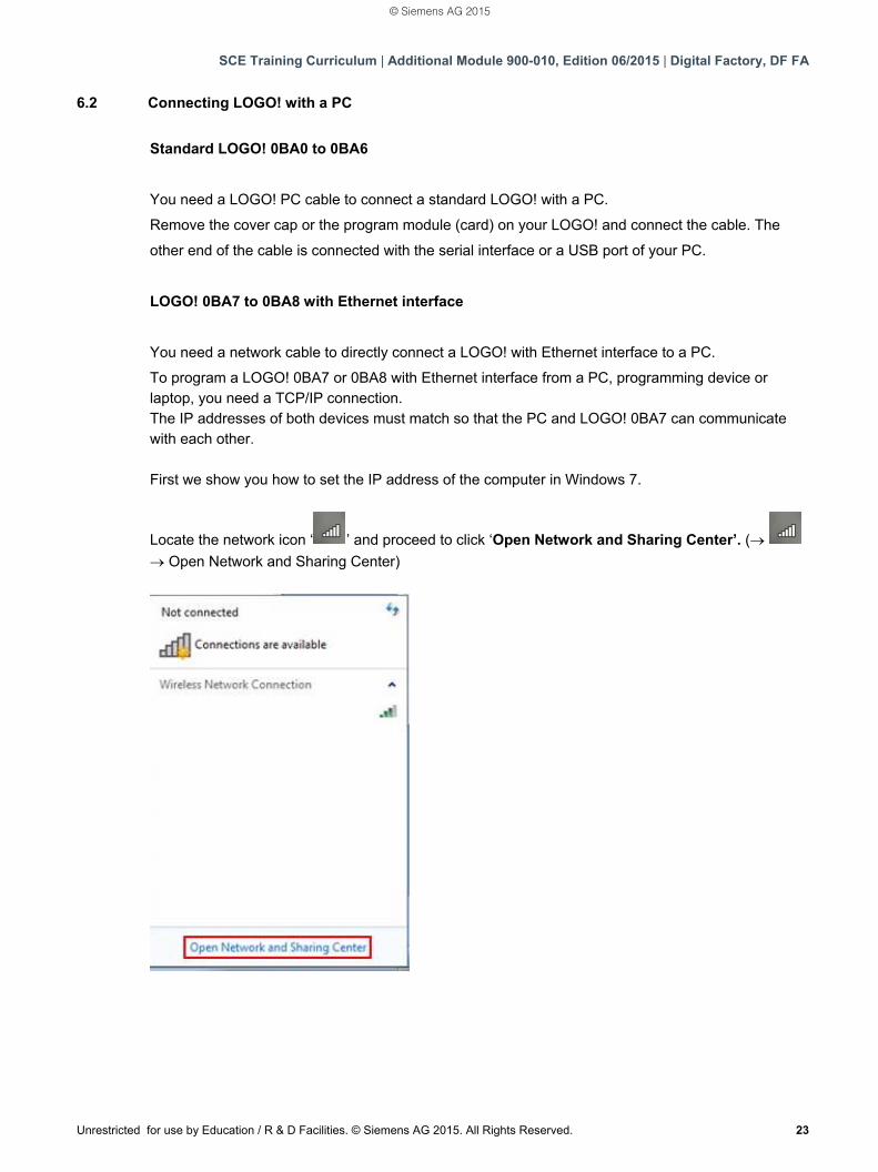
Locate the network icon ‘ ’ and proceed to click ‘Open Network and Sharing Center’. (
Open Network and Sharing Center)
© Siemens AG 2015
SCE Training Curriculum | Additional Module 900-010, Edition 06/2015 | Digital Factory, DF FA
24 Unrestricted for use by Education / R & D Facilities. © Siemens AG 2015. All Rights Reserved.
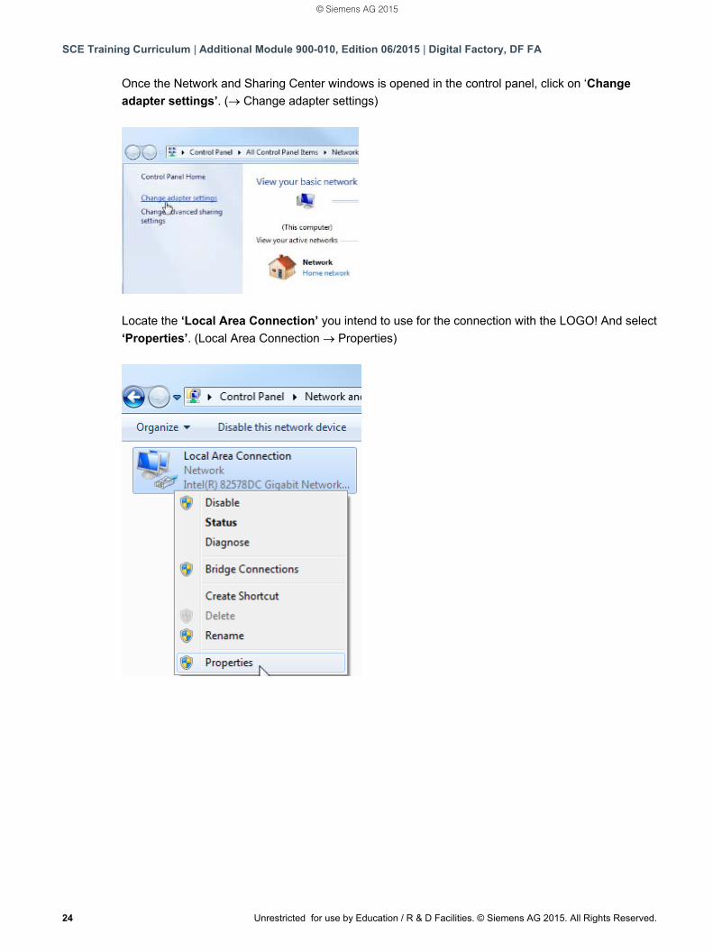
Once the Network and Sharing Center windows is opened in the control panel, click on ‘Change
adapter settings’. ( Change adapter settings)
Locate the ‘Local Area Connection’ you intend to use for the connection with the LOGO! And select
‘Properties’. (Local Area Connection Properties)
© Siemens AG 2015
SCE Training Curriculum | Additional Module 900-010, Edition 06/2015 | Digital Factory, DF FA
Unrestricted for use by Education / R & D Facilities. © Siemens AG 2015. All Rights Reserved. 25
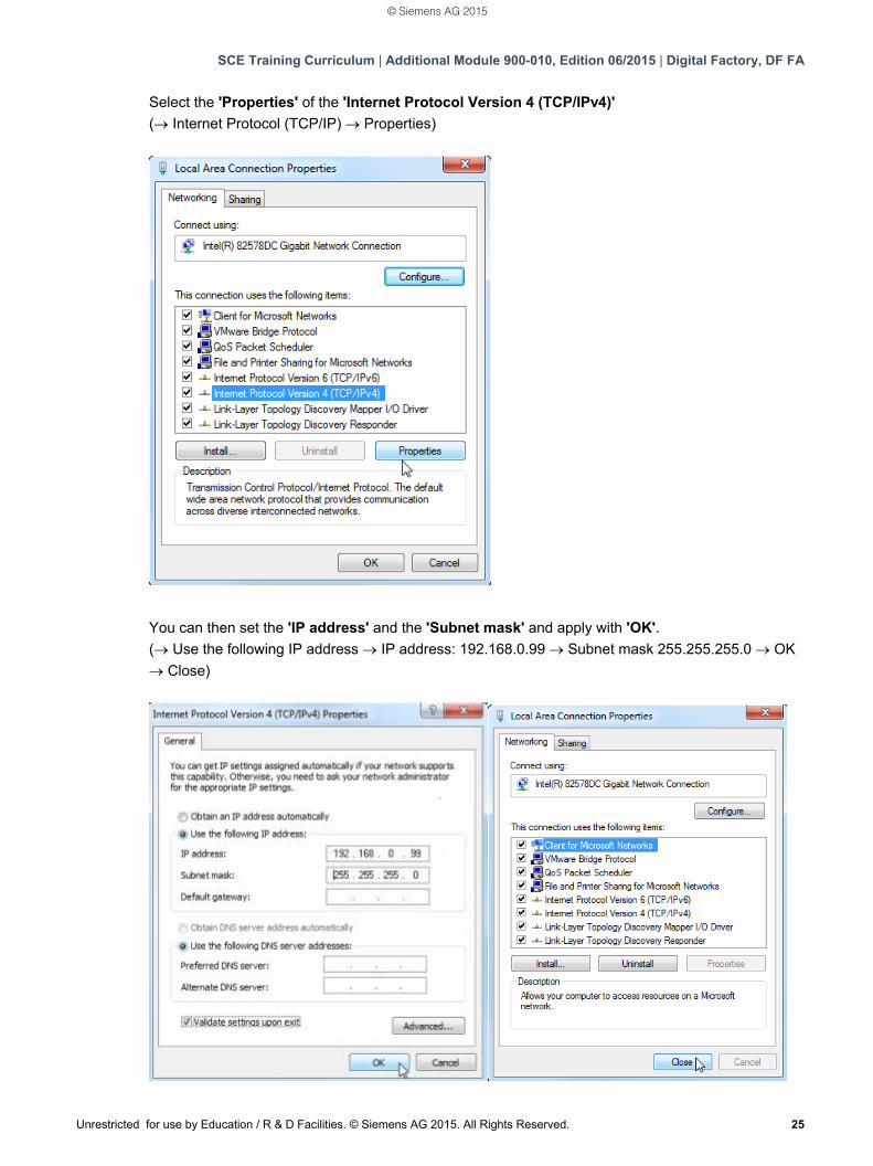
Select the 'Properties' of the 'Internet Protocol Version 4 (TCP/IPv4)'
( Internet Protocol (TCP/IP) Properties)
You can then set the 'IP address' and the 'Subnet mask' and apply with 'OK'.
( Use the following IP address IP address: 192.168.0.99 Subnet mask 255.255.255.0 OK
Close)
© Siemens AG 2015
SCE Training Curriculum | Additional Module 900-010, Edition 06/2015 | Digital Factory, DF FA
26 Unrestricted for use by Education / R & D Facilities. © Siemens AG 2015. All Rights Reserved.
Notes for networking on Ethernet
MAC address: The MAC address consists of a fixed and a variable part. The fixed part ("base MAC address") identifies the manufacturer (Siemens, 3COM, ...). The variable part of the MAC address differentiates between the various Ethernet devices and should be unique worldwide. A factory-assigned MAC address is imprinted on each module. Value range for the IP address: The IP address consists of 4 decimal numbers of the range from 0 to 255, separated by a period; for example, 141.80.0.16. Value range for the subnet mask: This mask is used to detect whether a device or its IP address belongs to the local subnet, or can be accessed only by means of a router. The subnet mask consists of 4 decimal numbers from the value range 0 to 255, separated by a period. For example, 255.255.0.0. In their binary representation, the 4 decimal numbers of the subnet mask must include a continuous series of "1" values without any gaps from the left and a series of "0" values without any gaps from the right. The "1" values specify the area of the IP address for the network number. The "0" values specify the area of the IP address for the device address. Example: Correct value: 255.255.0.0 decimal = 1111 1111.1111 1111.0000 0000.0000 0000 binary 255.255.128.0 decimal = 1111 1111.1111 1111.1000 0000.0000 0000 binary 255.254.0.0 decimal = 1111 1111.1111 1110.0000 0000.0000.0000 binary Incorrect value: 255.255.1.0 decimal = 1111 1111.1111 1111.0000 0001.0000 0000 binary Value range for the address of the gateway (router): The address consists of 4 decimal numbers from the value range 0 to 255, separated by a period. For example, 141.80.0.1. Relation of IP addresses, router address, and subnet mask: The IP address and the address of the gateway may only differ at the positions at which there is a "0" in the subnet mask. Example: You have entered the following: for the subnet mask 255.255.255.0, for the IP address 141.30.0.5 and for the router address 141.30.128.1. The IP address and the address of the gateway may only have a different value in the 4th decimal number. In the example, however, the 3rd position is different. In the example, you will therefore need to make one of the following changes: - The subnet mask to: 255.255.0.0 or - The IP address to: 141.30.128.5 or - The address of the gateway to: 141.30.0.1
© Siemens AG 2015
SCE Training Curriculum | Additional Module 900-010, Edition 06/2015 | Digital Factory, DF FA
Unrestricted for use by Education / R & D Facilities. © Siemens AG 2015. All Rights Reserved. 27
7. COMMISSIONING A LOGO! 0BA7 WITH LOGO!SOFT COMFORT V7.1
7.1 Setting the IP address of LOGO! 0BA7
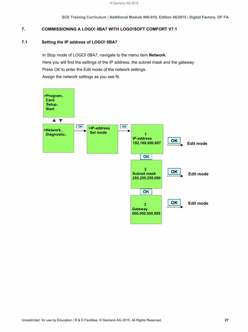
In Stop mode of LOGO! 0BA7, navigate to the menu item Network.
Here you will find the settings of the IP address, the subnet mask and the gateway.
Press OK to enter the Edit mode of the network settings.
Assign the network settings as you see fit.
Edit mode
Edit mode
Edit mode
OK
OK
OK
>Program.. Card
Setup.. Start
>Network.. Diagnostic..
>IP-address Set mode
1
IP-address 192.168.000.007
2 Subnet mask 255.255.255.000
3 Gateway 000.000.000.000
© Siemens AG 2015
SCE Training Curriculum | Additional Module 900-010, Edition 06/2015 | Digital Factory, DF FA
28 Unrestricted for use by Education / R & D Facilities. © Siemens AG 2015. All Rights Reserved.
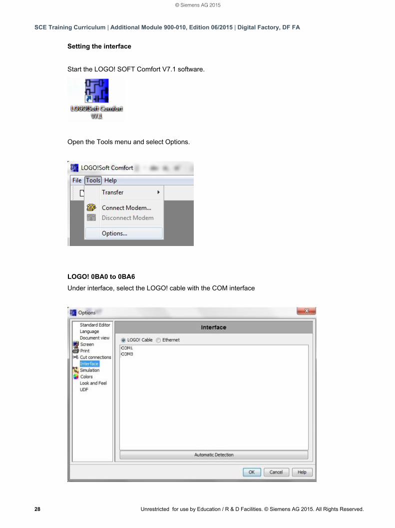
Setting the interface
Start the LOGO! SOFT Comfort V7.1 software.
Open the Tools menu and select Options.
LOGO! 0BA0 to 0BA6
Under interface, select the LOGO! cable with the COM interface
© Siemens AG 2015
SCE Training Curriculum | Additional Module 900-010, Edition 06/2015 | Digital Factory, DF FA
Unrestricted for use by Education / R & D Facilities. © Siemens AG 2015. All Rights Reserved. 29
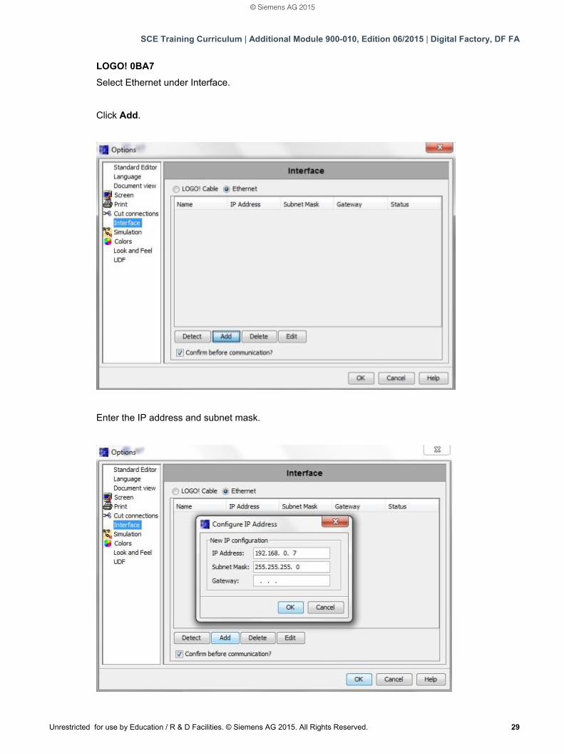
LOGO! 0BA7
Select Ethernet under Interface.
Click Add.
Enter the IP address and subnet mask.
© Siemens AG 2015
SCE Training Curriculum | Additional Module 900-010, Edition 06/2015 | Digital Factory, DF FA
30 Unrestricted for use by Education / R & D Facilities. © Siemens AG 2015. All Rights Reserved.
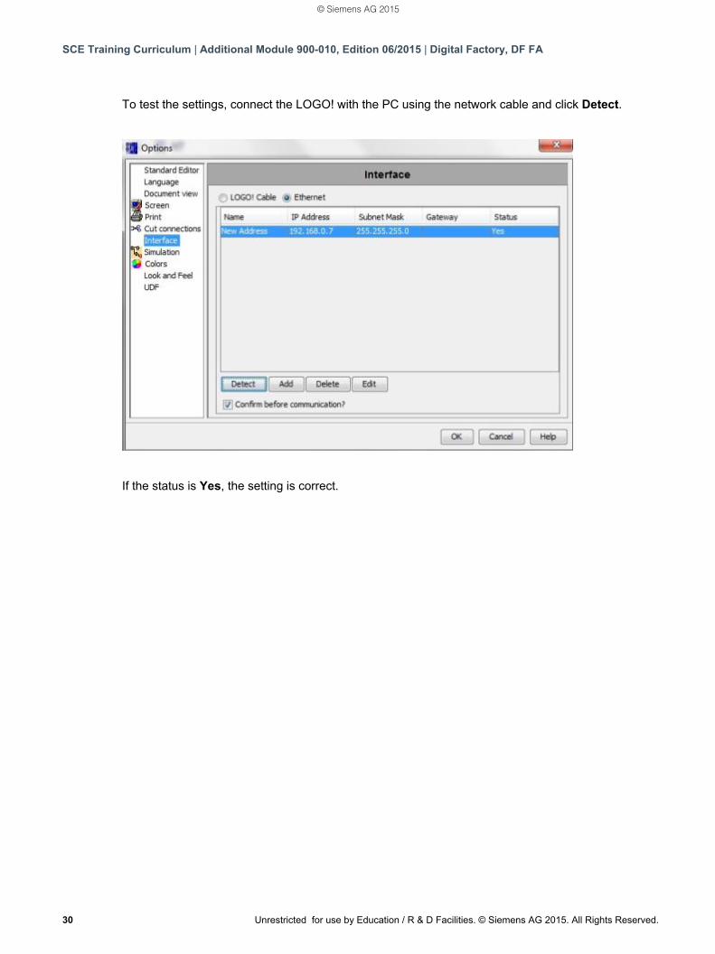
To test the settings, connect the LOGO! with the PC using the network cable and click Detect.
If the status is Yes, the setting is correct.
© Siemens AG 2015
SCE Training Curriculum | Additional Module 900-010, Edition 06/2015 | Digital Factory, DF FA
Unrestricted for use by Education / R & D Facilities. © Siemens AG 2015. All Rights Reserved. 31
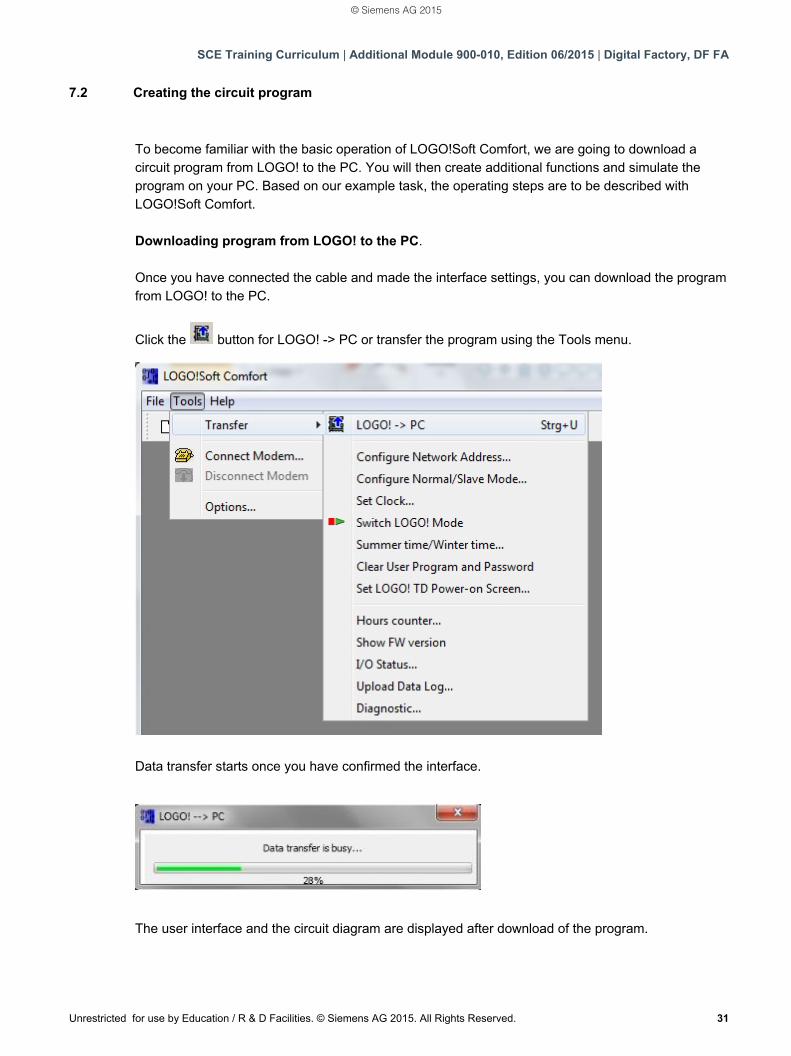
7.2 Creating the circuit program
To become familiar with the basic operation of LOGO!Soft Comfort, we are going to download a circuit program from LOGO! to the PC. You will then create additional functions and simulate the program on your PC. Based on our example task, the operating steps are to be described with LOGO!Soft Comfort. Downloading program from LOGO! to the PC. Once you have connected the cable and made the interface settings, you can download the program from LOGO! to the PC.
Click the button for LOGO! -> PC or transfer the program using the Tools menu.
Data transfer starts once you have confirmed the interface.
The user interface and the circuit diagram are displayed after download of the program.
© Siemens AG 2015
SCE Training Curriculum | Additional Module 900-010, Edition 06/2015 | Digital Factory, DF FA
32 Unrestricted for use by Education / R & D Facilities. © Siemens AG 2015. All Rights Reserved.
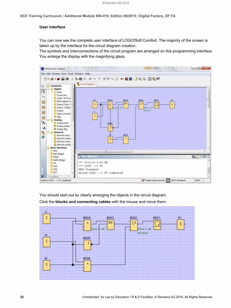
User interface
You can now see the complete user interface of LOGO!Soft Comfort. The majority of the screen is taken up by the interface for the circuit diagram creation. The symbols and interconnections of the circuit program are arranged on this programming interface. You enlarge the display with the magnifying glass.
You should start out by clearly arranging the objects in the circuit diagram.
Click the blocks and connecting cables with the mouse and move them.
© Siemens AG 2015
SCE Training Curriculum | Additional Module 900-010, Edition 06/2015 | Digital Factory, DF FA
Unrestricted for use by Education / R & D Facilities. © Siemens AG 2015. All Rights Reserved. 33
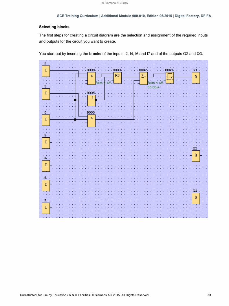
Selecting blocks
The first steps for creating a circuit diagram are the selection and assignment of the required inputs
and outputs for the circuit you want to create.
You start out by inserting the blocks of the inputs I2, I4, I6 and I7 and of the outputs Q2 and Q3.
© Siemens AG 2015
SCE Training Curriculum | Additional Module 900-010, Edition 06/2015 | Digital Factory, DF FA
34 Unrestricted for use by Education / R & D Facilities. © Siemens AG 2015. All Rights Reserved.
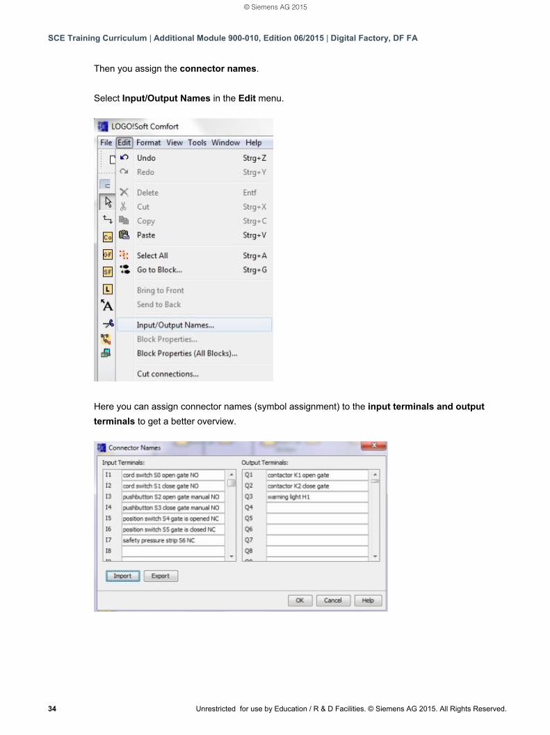
Then you assign the connector names.
Select Input/Output Names in the Edit menu.
Here you can assign connector names (symbol assignment) to the input terminals and output
terminals to get a better overview.
© Siemens AG 2015
SCE Training Curriculum | Additional Module 900-010, Edition 06/2015 | Digital Factory, DF FA
Unrestricted for use by Education / R & D Facilities. © Siemens AG 2015. All Rights Reserved. 35
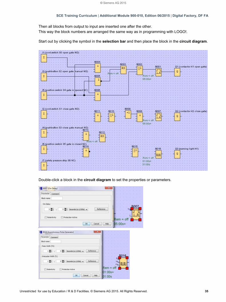
Then all blocks from output to input are inserted one after the other. This way the block numbers are arranged the same way as in programming with LOGO!. Start out by clicking the symbol in the selection bar and then place the block in the circuit diagram.
Double-click a block in the circuit diagram to set the properties or parameters.
© Siemens AG 2015
SCE Training Curriculum | Additional Module 900-010, Edition 06/2015 | Digital Factory, DF FA
36 Unrestricted for use by Education / R & D Facilities. © Siemens AG 2015. All Rights Reserved.
Connecting blocks
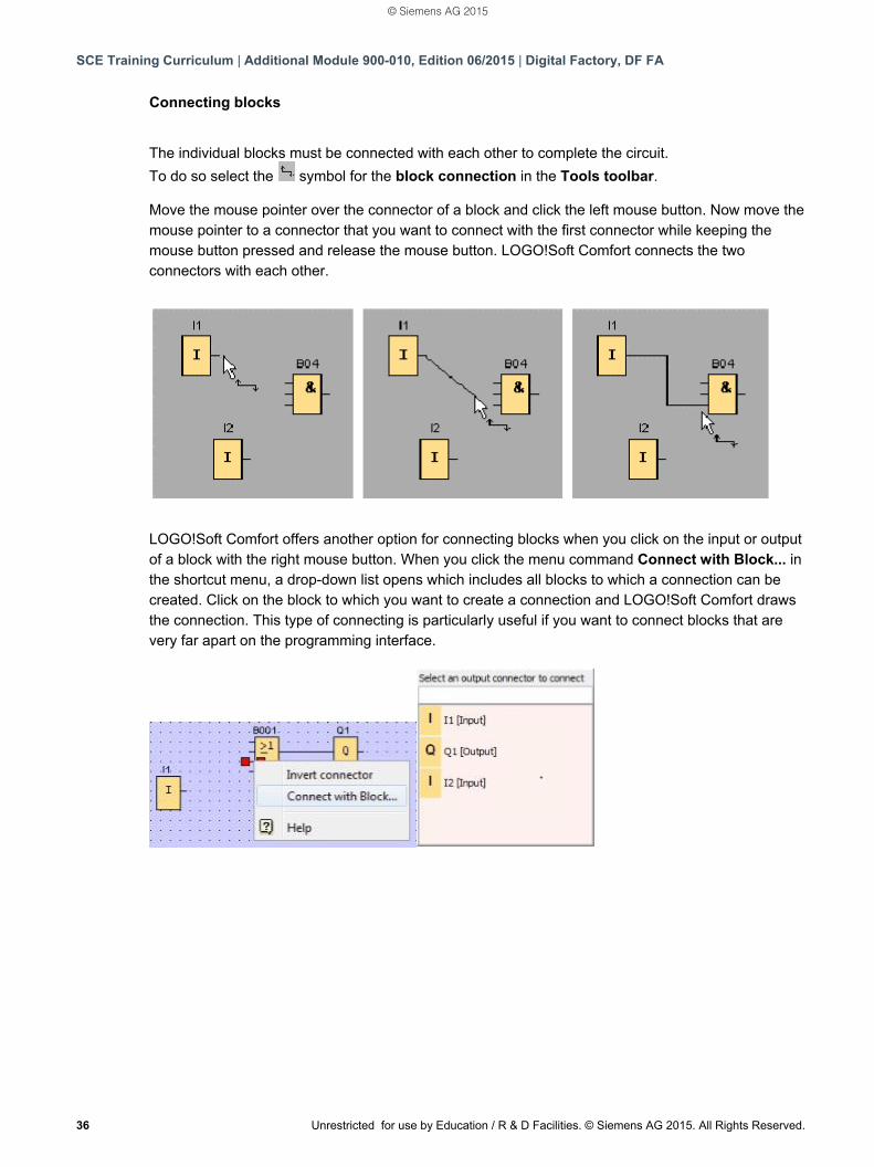
The individual blocks must be connected with each other to complete the circuit.
To do so select the symbol for the block connection in the Tools toolbar. Move the mouse pointer over the connector of a block and click the left mouse button. Now move the mouse pointer to a connector that you want to connect with the first connector while keeping the mouse button pressed and release the mouse button. LOGO!Soft Comfort connects the two connectors with each other.
LOGO!Soft Comfort offers another option for connecting blocks when you click on the input or output of a block with the right mouse button. When you click the menu command Connect with Block... in the shortcut menu, a drop-down list opens which includes all blocks to which a connection can be created. Click on the block to which you want to create a connection and LOGO!Soft Comfort draws the connection. This type of connecting is particularly useful if you want to connect blocks that are very far apart on the programming interface.
© Siemens AG 2015
SCE Training Curriculum | Additional Module 900-010, Edition 06/2015 | Digital Factory, DF FA
Unrestricted for use by Education / R & D Facilities. © Siemens AG 2015. All Rights Reserved. 37
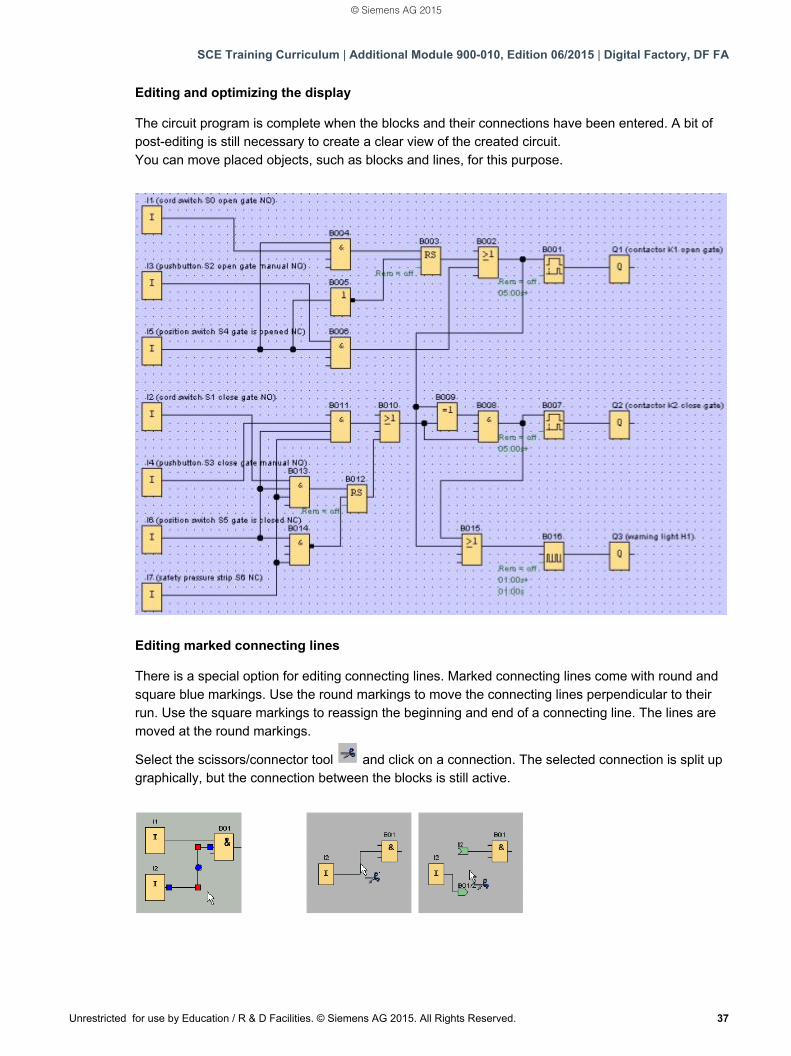
Editing and optimizing the display The circuit program is complete when the blocks and their connections have been entered. A bit of post-editing is still necessary to create a clear view of the created circuit. You can move placed objects, such as blocks and lines, for this purpose.
Editing marked connecting lines There is a special option for editing connecting lines. Marked connecting lines come with round and square blue markings. Use the round markings to move the connecting lines perpendicular to their run. Use the square markings to reassign the beginning and end of a connecting line. The lines are moved at the round markings.
Select the scissors/connector tool and click on a connection. The selected connection is split up graphically, but the connection between the blocks is still active.
© Siemens AG 2015
SCE Training Curriculum | Additional Module 900-010, Edition 06/2015 | Digital Factory, DF FA
38 Unrestricted for use by Education / R & D Facilities. © Siemens AG 2015. All Rights Reserved.
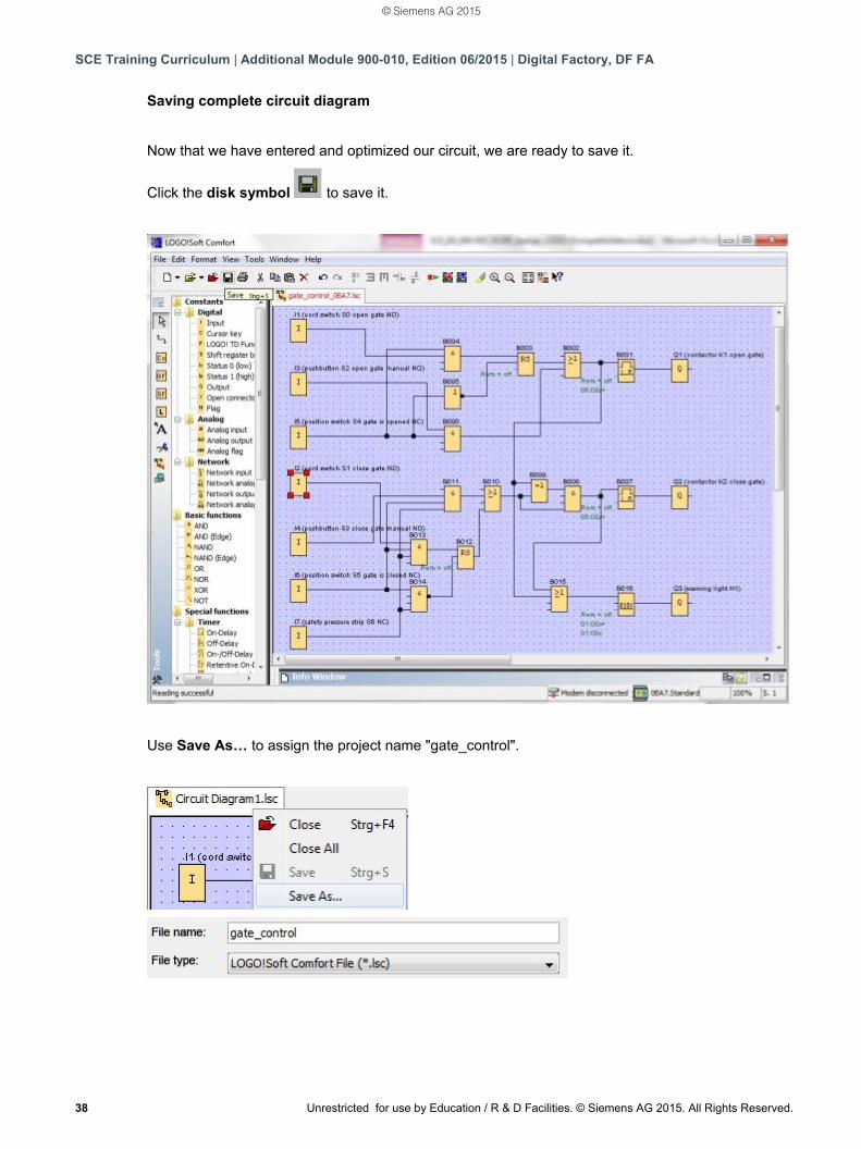
Saving complete circuit diagram
Now that we have entered and optimized our circuit, we are ready to save it.
Click the disk symbol to save it.
Use Save As… to assign the project name "gate_control".
© Siemens AG 2015
SCE Training Curriculum | Additional Module 900-010, Edition 06/2015 | Digital Factory, DF FA
Unrestricted for use by Education / R & D Facilities. © Siemens AG 2015. All Rights Reserved. 39
7.3 Simulation of the circuit
A circuit program can be tested with the program simulation and edited regarding its parameter
assignment. This way you can ensure that you transfer a functioning and optimized circuit program
to your LOGO!.
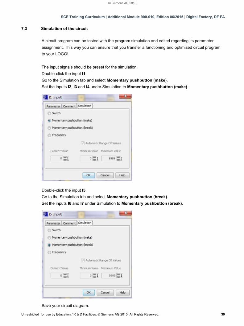
The input signals should be preset for the simulation.
Double-click the input I1.
Go to the Simulation tab and select Momentary pushbutton (make).
Set the inputs I2, I3 and I4 under Simulation to Momentary pushbutton (make).
Double-click the input I5.
Go to the Simulation tab and select Momentary pushbutton (break).
Set the inputs I6 and I7 under Simulation to Momentary pushbutton (break).
Save your circuit diagram.
© Siemens AG 2015
SCE Training Curriculum | Additional Module 900-010, Edition 06/2015 | Digital Factory, DF FA
40 Unrestricted for use by Education / R & D Facilities. © Siemens AG 2015. All Rights Reserved.
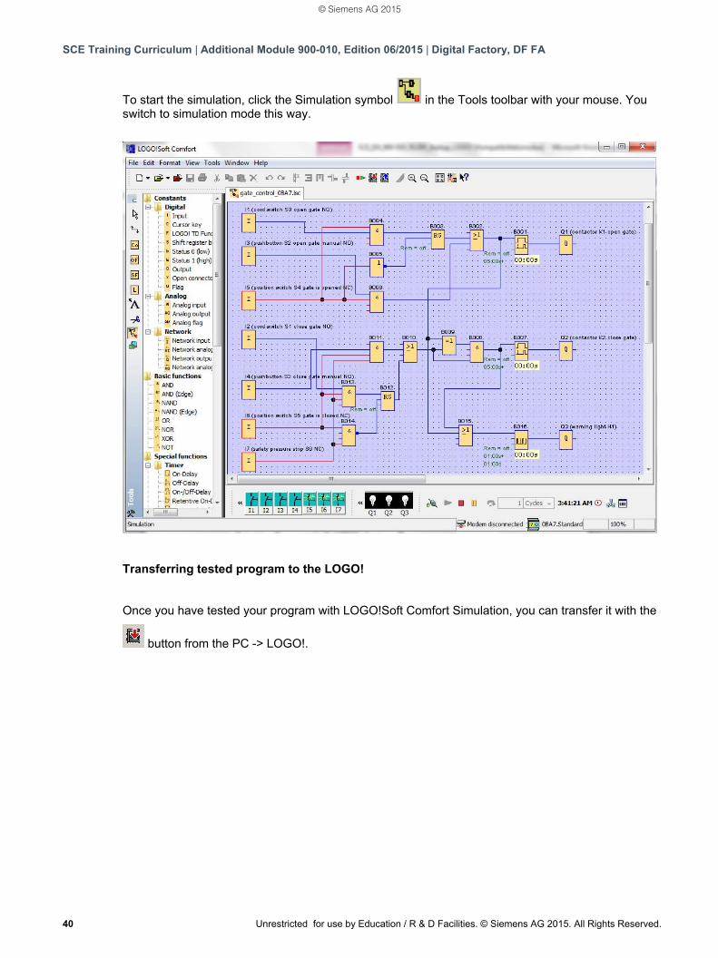
To start the simulation, click the Simulation symbol in the Tools toolbar with your mouse. You switch to simulation mode this way.
Transferring tested program to the LOGO!
Once you have tested your program with LOGO!Soft Comfort Simulation, you can transfer it with the
button from the PC -> LOGO!.
© Siemens AG 2015
SCE Training Curriculum | Additional Module 900-010, Edition 06/2015 | Digital Factory, DF FA
Unrestricted for use by Education / R & D Facilities. © Siemens AG 2015. All Rights Reserved. 41
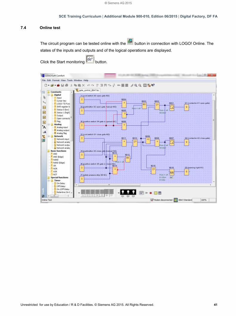
7.4 Online test
The circuit program can be tested online with the button in connection with LOGO! Online. The
states of the inputs and outputs and of the logical operations are displayed.
Click the Start monitoring button.
© Siemens AG 2015
SCE Training Curriculum | Additional Module 900-010, Edition 06/2015 | Digital Factory, DF FA
42 Unrestricted for use by Education / R & D Facilities. © Siemens AG 2015. All Rights Reserved.
8. COMMISSIONING A LOGO! 0BA8 WITH LOGO!SOFT COMFORT V8.0
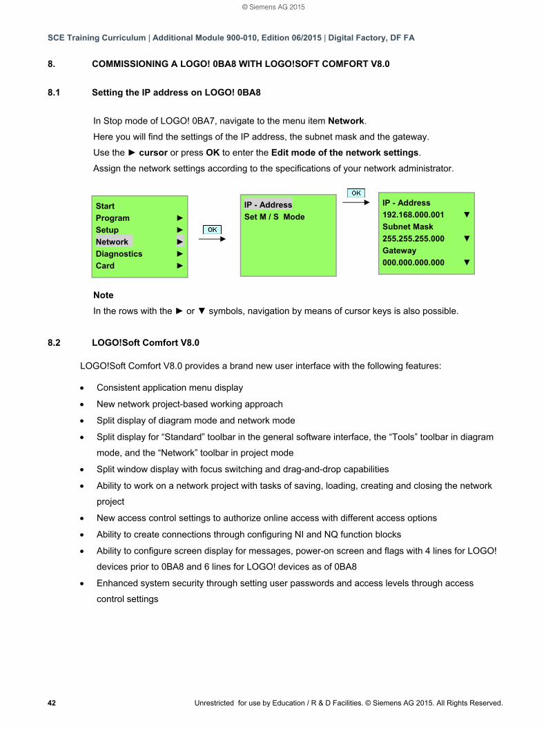
8.1 Setting the IP address on LOGO! 0BA8
In Stop mode of LOGO! 0BA7, navigate to the menu item Network.
Here you will find the settings of the IP address, the subnet mask and the gateway.
Use the ► cursor or press OK to enter the Edit mode of the network settings.
Assign the network settings according to the specifications of your network administrator.
Note
In the rows with the ► or ▼ symbols, navigation by means of cursor keys is also possible.
8.2 LOGO!Soft Comfort V8.0 LOGO!Soft Comfort V8.0 provides a brand new user interface with the following features:
Consistent application menu display
New network project-based working approach
Split display of diagram mode and network mode
Split display for “Standard” toolbar in the general software interface, the “Tools” toolbar in diagram
mode, and the “Network” toolbar in project mode
Split window display with focus switching and drag-and-drop capabilities
Ability to work on a network project with tasks of saving, loading, creating and closing the network
project
New access control settings to authorize online access with different access options
Ability to create connections through configuring NI and NQ function blocks
Ability to configure screen display for messages, power-on screen and flags with 4 lines for LOGO!
devices prior to 0BA8 and 6 lines for LOGO! devices as of 0BA8
Enhanced system security through setting user passwords and access levels through access
control settings
Start
Program ►
Setup ►
Network ►
Diagnostics ►
Card ►
IP - Address
Set M / S Mode
IP - Address
192.168.000.001 ▼
Subnet Mask
255.255.255.000 ▼
Gateway
000.000.000.000 ▼
© Siemens AG 2015
SCE Training Curriculum | Additional Module 900-010, Edition 06/2015 | Digital Factory, DF FA
Unrestricted for use by Education / R & D Facilities. © Siemens AG 2015. All Rights Reserved. 43
8.3 User interface of LOGO!Soft Comfort V8.0
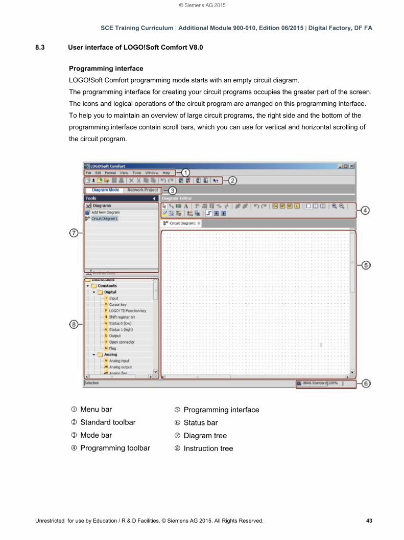
Programming interface
LOGO!Soft Comfort programming mode starts with an empty circuit diagram.
The programming interface for creating your circuit programs occupies the greater part of the screen.
The icons and logical operations of the circuit program are arranged on this programming interface.
To help you to maintain an overview of large circuit programs, the right side and the bottom of the
programming interface contain scroll bars, which you can use for vertical and horizontal scrolling of
the circuit program.
Menu bar
Standard toolbar
Mode bar
Programming toolbar
Programming interface
Status bar
Diagram tree
Instruction tree
© Siemens AG 2015
SCE Training Curriculum | Additional Module 900-010, Edition 06/2015 | Digital Factory, DF FA
44 Unrestricted for use by Education / R & D Facilities. © Siemens AG 2015. All Rights Reserved.
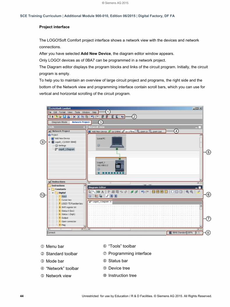
Project interface
The LOGO!Soft Comfort project interface shows a network view with the devices and network
connections.
After you have selected Add New Device, the diagram editor window appears.
Only LOGO! devices as of 0BA7 can be programmed in a network project.
The Diagram editor displays the program blocks and links of the circuit program. Initially, the circuit
program is empty.
To help you to maintain an overview of large circuit project and programs, the right side and the
bottom of the Network view and programming interface contain scroll bars, which you can use for
vertical and horizontal scrolling of the circuit program.
Menu bar
Standard toolbar
Mode bar
“Network” toolbar
Network view
“Tools” toolbar
Programming interface
Status bar
Device tree
Instruction tree
© Siemens AG 2015
SCE Training Curriculum | Additional Module 900-010, Edition 06/2015 | Digital Factory, DF FA
Unrestricted for use by Education / R & D Facilities. © Siemens AG 2015. All Rights Reserved. 45
9. PROJECT PLANT GATE CONTROL WITH LOGO!SOFT COMFORT V8.0 AND LOGO! 0BA8
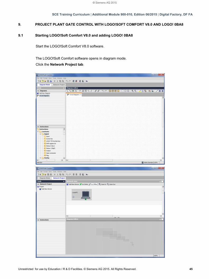
9.1 Starting LOGO!Soft Comfort V8.0 and adding LOGO! 0BA8
Start the LOGO!Soft Comfort V8.0 software.
The LOGO!Soft Comfort software opens in diagram mode.
Click the Network Project tab.
© Siemens AG 2015
SCE Training Curriculum | Additional Module 900-010, Edition 06/2015 | Digital Factory, DF FA
46 Unrestricted for use by Education / R & D Facilities. © Siemens AG 2015. All Rights Reserved.
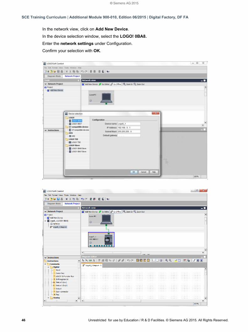
In the network view, click on Add New Device.
In the device selection window, select the LOGO! 0BA8.
Enter the network settings under Configuration.
Confirm your selection with OK.
© Siemens AG 2015
SCE Training Curriculum | Additional Module 900-010, Edition 06/2015 | Digital Factory, DF FA
Unrestricted for use by Education / R & D Facilities. © Siemens AG 2015. All Rights Reserved. 47
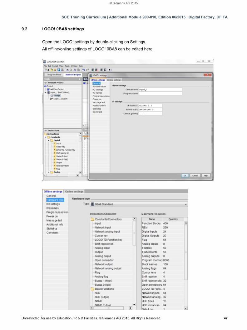
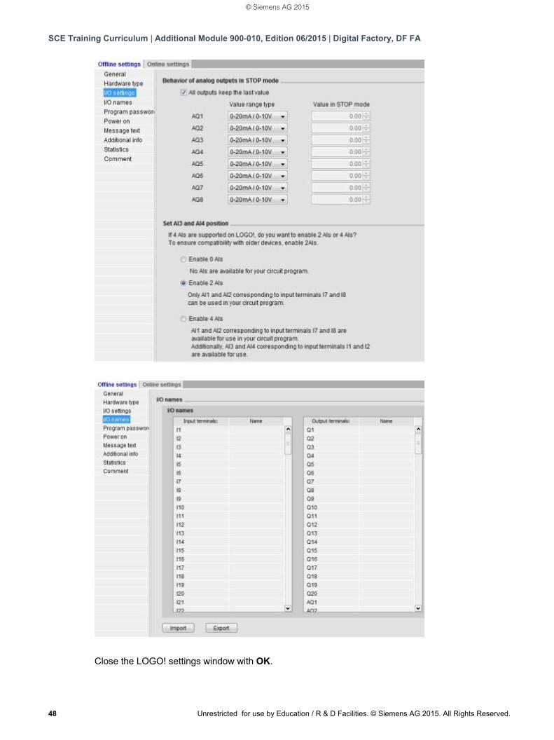
9.2 LOGO! 0BA8 settings
Open the LOGO! settings by double-clicking on Settings.
All offline/online settings of LOGO! 0BA8 can be edited here.
© Siemens AG 2015
SCE Training Curriculum | Additional Module 900-010, Edition 06/2015 | Digital Factory, DF FA
48 Unrestricted for use by Education / R & D Facilities. © Siemens AG 2015. All Rights Reserved.
Close the LOGO! settings window with OK.
© Siemens AG 2015
SCE Training Curriculum | Additional Module 900-010, Edition 06/2015 | Digital Factory, DF FA
Unrestricted for use by Education / R & D Facilities. © Siemens AG 2015. All Rights Reserved. 49
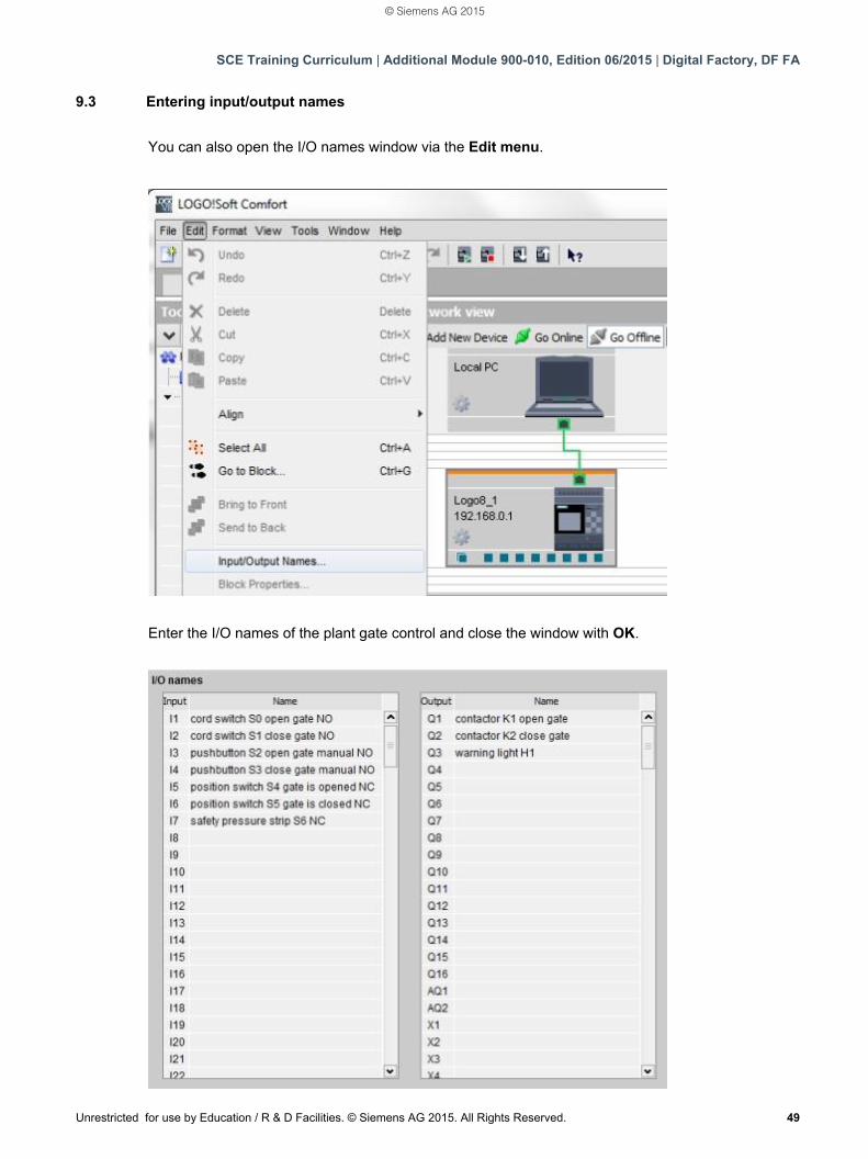
9.3 Entering input/output names
You can also open the I/O names window via the Edit menu.
Enter the I/O names of the plant gate control and close the window with OK.
© Siemens AG 2015
SCE Training Curriculum | Additional Module 900-010, Edition 06/2015 | Digital Factory, DF FA
50 Unrestricted for use by Education / R & D Facilities. © Siemens AG 2015. All Rights Reserved.
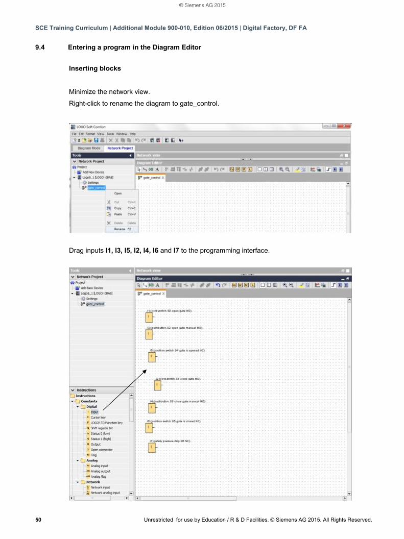
9.4 Entering a program in the Diagram Editor
Inserting blocks
Minimize the network view.
Right-click to rename the diagram to gate_control.
Drag inputs I1, I3, I5, I2, I4, I6 and I7 to the programming interface.
© Siemens AG 2015
SCE Training Curriculum | Additional Module 900-010, Edition 06/2015 | Digital Factory, DF FA
Unrestricted for use by Education / R & D Facilities. © Siemens AG 2015. All Rights Reserved. 51
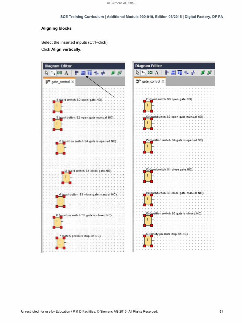
Aligning blocks
Select the inserted inputs (Ctrl+click).
Click Align vertically.
© Siemens AG 2015
SCE Training Curriculum | Additional Module 900-010, Edition 06/2015 | Digital Factory, DF FA
52 Unrestricted for use by Education / R & D Facilities. © Siemens AG 2015. All Rights Reserved.
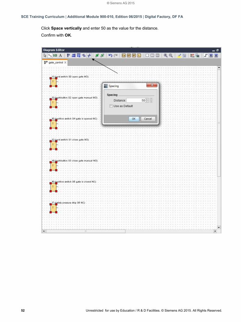
Click Space vertically and enter 50 as the value for the distance.
Confirm with OK.
© Siemens AG 2015
SCE Training Curriculum | Additional Module 900-010, Edition 06/2015 | Digital Factory, DF FA
Unrestricted for use by Education / R & D Facilities. © Siemens AG 2015. All Rights Reserved. 53
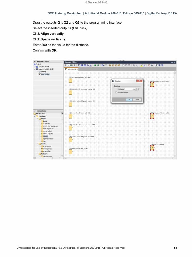
Drag the outputs Q1, Q2 and Q3 to the programming interface.
Select the inserted outputs (Ctrl+click).
Click Align vertically.
Click Space vertically.
Enter 200 as the value for the distance.
Confirm with OK.
© Siemens AG 2015
SCE Training Curriculum | Additional Module 900-010, Edition 06/2015 | Digital Factory, DF FA
54 Unrestricted for use by Education / R & D Facilities. © Siemens AG 2015. All Rights Reserved.
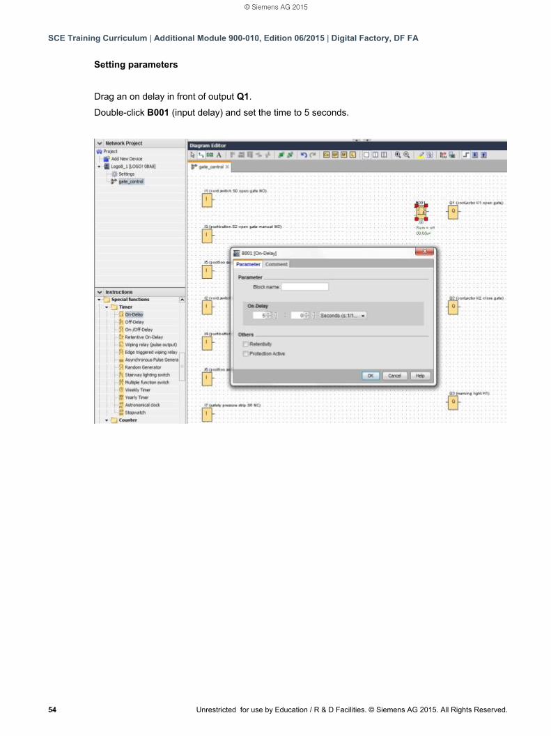
Setting parameters
Drag an on delay in front of output Q1.
Double-click B001 (input delay) and set the time to 5 seconds.
© Siemens AG 2015
SCE Training Curriculum | Additional Module 900-010, Edition 06/2015 | Digital Factory, DF FA
Unrestricted for use by Education / R & D Facilities. © Siemens AG 2015. All Rights Reserved. 55
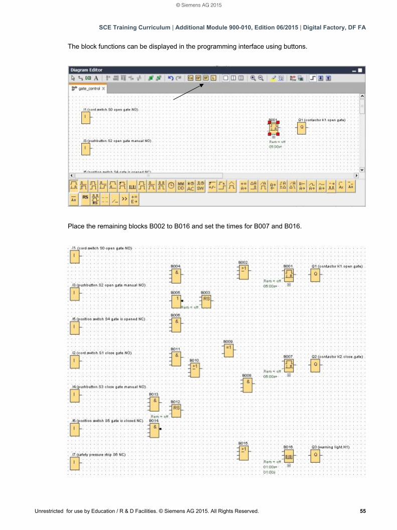
The block functions can be displayed in the programming interface using buttons.
Place the remaining blocks B002 to B016 and set the times for B007 and B016.
© Siemens AG 2015
SCE Training Curriculum | Additional Module 900-010, Edition 06/2015 | Digital Factory, DF FA
56 Unrestricted for use by Education / R & D Facilities. © Siemens AG 2015. All Rights Reserved.
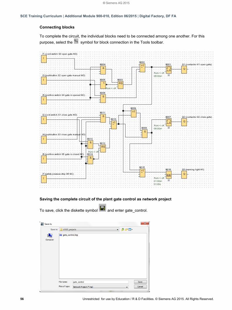
Connecting blocks To complete the circuit, the individual blocks need to be connected among one another. For this
purpose, select the symbol for block connection in the Tools toolbar.
Saving the complete circuit of the plant gate control as network project
To save, click the diskette symbol and enter gate_control.
© Siemens AG 2015
SCE Training Curriculum | Additional Module 900-010, Edition 06/2015 | Digital Factory, DF FA
Unrestricted for use by Education / R & D Facilities. © Siemens AG 2015. All Rights Reserved. 57
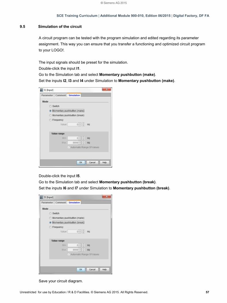
9.5 Simulation of the circuit
A circuit program can be tested with the program simulation and edited regarding its parameter
assignment. This way you can ensure that you transfer a functioning and optimized circuit program
to your LOGO!.
The input signals should be preset for the simulation.
Double-click the input I1.
Go to the Simulation tab and select Momentary pushbutton (make).
Set the inputs I2, I3 and I4 under Simulation to Momentary pushbutton (make).
Double-click the input I5.
Go to the Simulation tab and select Momentary pushbutton (break).
Set the inputs I6 and I7 under Simulation to Momentary pushbutton (break).
Save your circuit diagram.
© Siemens AG 2015
SCE Training Curriculum | Additional Module 900-010, Edition 06/2015 | Digital Factory, DF FA
58 Unrestricted for use by Education / R & D Facilities. © Siemens AG 2015. All Rights Reserved.
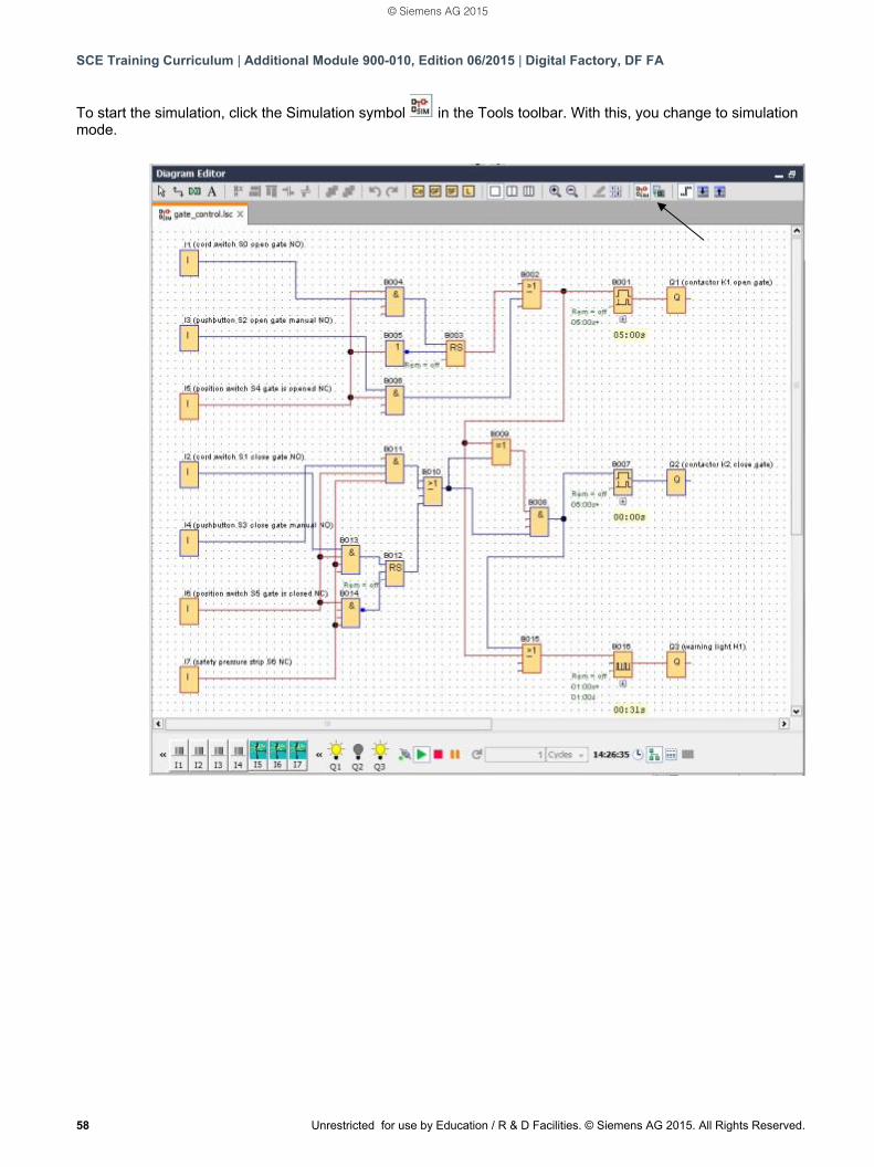
To start the simulation, click the Simulation symbol in the Tools toolbar. With this, you change to simulation mode.
© Siemens AG 2015
SCE Training Curriculum | Additional Module 900-010, Edition 06/2015 | Digital Factory, DF FA
Unrestricted for use by Education / R & D Facilities. © Siemens AG 2015. All Rights Reserved. 59
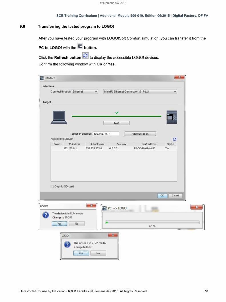
9.6 Transferring the tested program to LOGO!
After you have tested your program with LOGO!Soft Comfort simulation, you can transfer it from the
PC to LOGO! with the button.
Click the Refresh button to display the accessible LOGO! devices.
Confirm the following window with OK or Yes.
© Siemens AG 2015
SCE Training Curriculum | Additional Module 900-010, Edition 06/2015 | Digital Factory, DF FA
60 Unrestricted for use by Education / R & D Facilities. © Siemens AG 2015. All Rights Reserved.
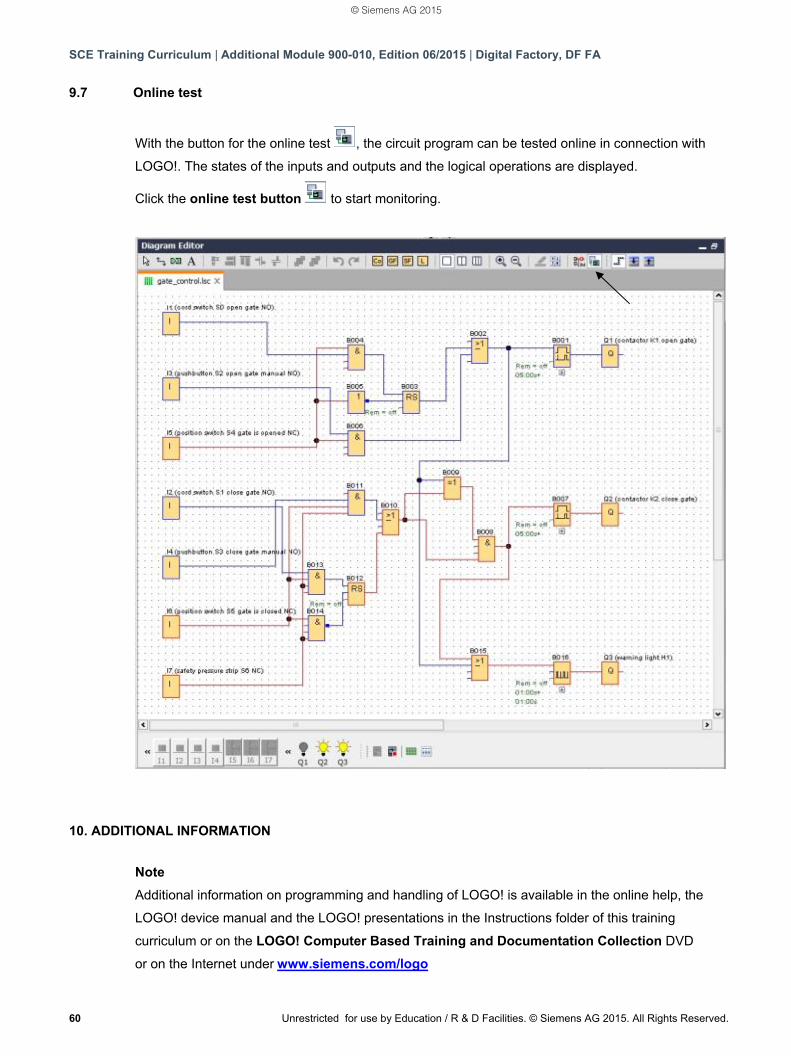
9.7 Online test
With the button for the online test , the circuit program can be tested online in connection with
LOGO!. The states of the inputs and outputs and the logical operations are displayed.
Click the online test button to start monitoring.
10. ADDITIONAL INFORMATION
Note
Additional information on programming and handling of LOGO! is available in the online help, the
LOGO! device manual and the LOGO! presentations in the Instructions folder of this training
curriculum or on the LOGO! Computer Based Training and Documentation Collection DVD
or on the Internet under www.siemens.com/logo
© Siemens AG 2015

Siemens Automation Cooperates with Education (SCE) focuses on the needs of students by providing educators with the tools and training to simplify their education in automation. The SCE program delivers value by offering specific courses, training curriculums and exceptional Hardware and Software Trainer Packages.
We are committed to sharing knowledge, resources and tools for teaching automation and drive system technologies through partnerships with educational institutions.
siemens.com/sce
Siemens Automation Cooperates with Education
Simplify your education in automationUnique support for educators and students in educational instutions
DRAFT Juni 30, 2015
© Siemens AG 2015
Get more information
Siemens Automation Cooperates with Education:www.siemens.com/sce
SCE training curriculums:www.siemens.com/sce/curriculums
SCE trainer packages:www.siemens.com/sce/tp
SCE contact partners:www.siemens.com/sce/contact
SCE Support Finder:www.siemens.com/sce/supportfinder
LOGO! Logic Module:www.siemens.com/logo
SIMATIC Controller:www.siemens.com/controller
Distributed IO:www.siemens.com/et200
Totally Integrated Automation:www.siemens.com/tia
Totally Integrated Automation Portal:www.siemens.com/tia-portal
SIMATIC Manual Guide:www.siemens.com/simatic-docu
Information material for SIMATIC:www.siemens.com/simatic/printmaterial
Siemens Industry Online Support ‒ Technical Forum:www.automation.siemens.com/WW/forum
Service&Support:www.siemens.com/automation/support
Other contact partners:www.siemens.com/automation/partners
Industry Mall for electronic ordering:www.siemens.com/industrymall
The information provided in this brochure contains merely general descriptions or characteristics of performance which in case of actual use do not always apply as described or which may change as a result of further development of the products. An obligation to provide the respective characteristics shall only exist if expressly agreed in the terms of contract. Availability and technical specifications are subject to change without notice. All product designations may be trademarks or product names of Siemens AG or supplier companies whose use by third parties for their own purposes could violate the rights of the owners.
Siemens AGDigital Factory DivisionFactory AutomationP.O. Box 48 4890026 NurembergGERMANY
Subject to change without prior noticeArticle No.6ZB5310-0QV02-0BA0B2112.W2.SCE.014 / Dispo 06321SO 0715 PDF 60 EnPrinted in Germany © Siemens AG 2015
siemens.com/sce
Industrial Security
Siemens provides products and solutions with industrial security functions that support the secure operation of plants, solutions, machines, equipment and/or networks. They are important components in a holistic industrial security concept. With this in mind, Siemens’ products and solutions undergo continuous development. Siemens recommends strongly that you regularly check for product updates.
For the secure operation of Siemens products and solutions, it is necessary to take suitable preventive action (e.g. cell protection concept) and integrate each component into a holistic, state-of-the-art industrial security concept. Third-party products that may be in use should also be considered. For more information about industrial security, visit http://www.siemens.com/industrialsecurity.
To stay informed about product updates as they occur, sign up for a product-specific newsletter. For more information, visit http://support.automation.siemens.com.
Umschlag SCE_LOGO.indd 2Umschlag SCE_LOGO.indd 2 08.07.2015 12:05:0108.07.2015 12:05:01
© Siemens AG 2015