Embed Size (px)
Citation preview

Composites: Part A 97 (2017) 41–50
Contents lists available at ScienceDirect
Composites: Part A
journal homepage: www.elsevier .com/locate /composi tesa
Long-fiber reinforced thermoplastic composite lattice structures:Fabrication and compressive properties
http://dx.doi.org/10.1016/j.compositesa.2017.03.0021359-835X/� 2017 Elsevier Ltd. All rights reserved.
⇑ Corresponding author at: School of Transportation Science & Engineering,Beihang University, Beijing 100191, China.
E-mail address: [email protected] (S. Yin).
Bo Xu a, Sha Yin b,c,⇑, Yang Wang a, Hongfu Li a, Boming Zhang a, Robert O. Ritchie d,e
a School of Materials Science & Engineering, Beihang University, Beijing 100191, Chinab School of Transportation Science & Engineering, Beihang University, Beijing 100191, ChinacAdvanced Vehicle Research Center, Beihang University, Beijing 100191, Chinad International Research Centre for Advanced Structural & Biomaterials, Beihang University, Beijing 100191, ChinaeDepartment of Materials Science & Engineering, University of California, Berkeley, CA 94720, USA
a r t i c l e i n f o a b s t r a c t
Article history:Received 15 November 2016Received in revised form 14 February 2017Accepted 2 March 2017Available online 4 March 2017
Keywords:Lattice structureAdditive manufacturingThermoplastic compositesMechanical properties
Recyclable lightweight materials with advanced processing techniques are essential for the sustainabledevelopment of future transportation. Thermoplastic composites lattice structures were developed tomeet this demand. An additive manufacturing method is presented here to fabricate such lattice struc-tures by reversible assembly of several long-fiber reinforced thermoplastic composite parts (LFTCPs)which were economically processed by injection molding. The resulting thermoplastic lattice structures(density of 30 kg�m�3) assembled with different sequences and connections are structurally evaluatedand compared. Out-of-plane compression tests revealed that their mechanical properties were more sen-sitive to the presence of the connections rather than their assembly sequence, although their structuralfailure mode was always brake of inclined struts followed by fracture of the horizontal struts. Potentialsolutions to the problem of internal stresses, induced during assembly, are also explored by designingnovel LFTCPs. The novel fabrication route for thermoplastic lattice structures will improve the prospectsfor their industrial application.
� 2017 Elsevier Ltd. All rights reserved.
1. Introduction
With the energy crisis and environmental pollution as majorworldwide problems, stringent regulations in CO2-emission andmaterials recyclability are becoming increasingly important inthe automotive and transportation industries. In this regard, theapplication of lightweight materials is an effective route for sus-tainable development of automotive structures, particularly withthe increasing use of composite materials. In contrast to othermajor applications of these materials, such as in aerospace engi-neering where the focus has been on properties and reliability,the future vehicle industry, such as for automotive, recoverablerockets, etc., tends to pay equal attention to manufacturing cost,time and uniformity, leading to their search for new lightweightmaterials with a high level of productivity and recycling potential.
Architected lattice materials are mechanical metamaterialswith periodically patterned micro-structures and high strength-and stiffness-to-weight ratios. Such materials can be constructed
with topologies exhibiting properties greatly superior to those bytheir stochastic analogues (e.g., foams) [1–4]. Cellular geometriesthat provide the highest effective modulus and strength arestretch-dominated with no bending of the individual truss mem-bers. Also, the resulting effective modulus and strength of idealstretch-dominated structures will scale linearly with relative den-sity [5]. Over the past decade, such lattice materials have been pre-sented as an exciting prospect for lightweight, multifunctionalmaterials, and indeed they have found several applications, suchas for airframes and sandwich panels for air blast protection,because of their superior specific strength, stiffness, large intercon-nected open space and potential for energy absorption [6–11]. Inthis regard, lattice composites which are fiber-reinforced compos-ites combined with lattice topologies, have further attracted partic-ular interest as they can enhance specific mechanical properties inengineered systems compared to their metallic counterparts [12–14]. Numerous manufacturing techniques have been developedfor these lattice composite materials, such as hot press molding[13,15], weaving [16,17], expansion [18] and interlocking [14],although their complexity and requirements of custom tooling,pressurization for consolidation and prolonged heating for matrixcuring have made these manufacturing processes both expensive
42 B. Xu et al. / Composites: Part A 97 (2017) 41–50
and time-consuming. In 2013, a reversible assembly, additive man-ufacturing, method was introduced by Cheung et al. [19] to fabri-cate cuboctahedron (body-centered cubic, BCC, type) lattice byusing many small identical parts as regular building blocks. Specif-ically, the thermoset composite digital elements that these authorsdesigned were made by filament winding; the resulting cellularcomposite materials were reported to possess an extremely largemeasured modulus for an ultralight material [19].
Compared to their thermoset counterparts, thermo-plastic com-posites have an advantage in recyclability which is crucial foradvanced vehicle industry [20]. Long-fiber reinforced thermoplas-tics (LFT) are usually prepared by an injection process using LFTpellets which are individual granulates with length of 10–25 mmsliced from continuous fibers with a polymer matrix surroundingthem by pultrusion process. Furthermore, the development oflong-fiber reinforced thermoplastics have undergone significantprogress of late with consistently high surface quality and highimpact resistance; accordingly, these additional economic benefitshave markedly promoted their application [21–23]. In this study,we present a means to manufacture architected thermoplasticcomposites for high volume and low cost applications by usingan additive manufacturing assembly methodology based on themethodology of Cheung et al. [19]. Distinct from the thermosetdigital elements used in Ref. [19], we used long-fiber reinforcedthermoplastic composite parts (LFTCPs), which were obtained byinjection molding; these provided improved surface quality and aconsiderable cost saving compared to winding. We examine herethe compressive behavior of such thermoplastic composites latticestructures with emphasis on the effects of assembly sequence andjoint connection.
2. Methods
2.1. Lattice fabrication
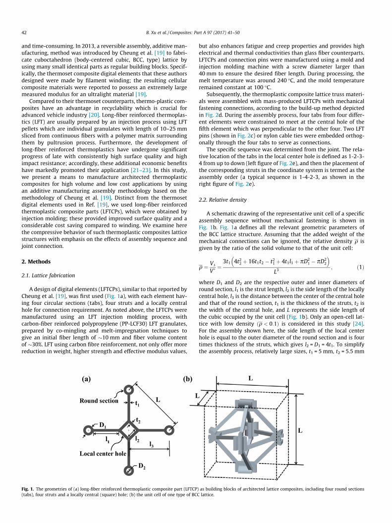
A design of digital elements (LFTCPs), similar to that reported byCheung et al. [19], was first used (Fig. 1a), with each element hav-ing four circular sections (tabs), four struts and a locally centralhole for connection requirement. As noted above, the LFTCPs weremanufactured using an LFT injection molding process, withcarbon-fiber reinforced polypropylene (PP-LCF30) LFT granulates,prepared by co-mingling and melt-impregnation techniques togive an initial fiber length of �10 mm and fiber volume contentof �30%. LFT using carbon fibre reinforcement, not only offer morereduction in weight, higher strength and effective modulus values,
Fig. 1. The geometries of (a) long-fiber reinforced thermoplastic composite part (LFTCP(tabs), four struts and a locally central (square) hole; (b) the unit cell of one type of BCC
but also enhances fatigue and creep properties and provides highelectrical and thermal conductivities than glass fiber counterparts.LFTCPs and connection pins were manufactured using a mold andinjection molding machine with a screw diameter larger than40 mm to ensure the desired fiber length. During processing, themelt temperature was around 240 �C, and the mold temperatureremained constant at 100 �C.
Subsequently, the thermoplastic composite lattice truss materi-als were assembled with mass-produced LFTCPs with mechanicalfastening connections, according to the build-up method depictedin Fig. 2d. During the assembly process, four tabs from four differ-ent elements were constrained to meet at the central hole of thefifth element which was perpendicular to the other four. Two LFTpins (shown in Fig. 2c) or nylon cable ties were embedded orthog-onally through the four tabs to serve as connections.
The specific sequence was determined from the joint. The rela-tive location of the tabs in the local center hole is defined as 1-2-3-4 from up to down (left figure of Fig. 2e), and then the placement ofthe corresponding struts in the coordinate system is termed as theassembly order (a typical sequence is 1-4-2-3, as shown in theright figure of Fig. 2e).
2.2. Relative density
A schematic drawing of the representative unit cell of a specificassembly sequence without mechanical fastening is shown inFig. 1b. Fig. 1a defines all the relevant geometric parameters ofthe BCC lattice structure. Assuming that the added weight of themechanical connections can be ignored, the relative density q isgiven by the ratio of the solid volume to that of the unit cell:
q ¼ Vs
V� ¼3t1 4t22 þ 16t1t2 � t21 þ 4t1l1 þ pD2
1 � pD22
� �
L3; ð1Þ
where D1 and D2 are the respective outer and inner diameters ofround section, l1 is the strut length, l2 is the side length of the locallycentral hole, l3 is the distance between the center of the central holeand that of the round section, t1 is the thickness of the struts, t2 isthe width of the central hole, and L represents the side length ofthe cubic occupied by the unit cell (Fig. 1b). Only an open-cell lat-tice with low density ðq < 0:1Þ is considered in this study [24].For the assembly shown here, the side length of the local centerhole is equal to the outer diameter of the round section and is fourtimes thickness of the struts, which gives l2 = D1 = 4t1. To simplifythe assembly process, relatively large sizes, t1 = 5 mm, t2 = 5.5 mm
) as building blocks of architected lattice composites, including four round sectionslattice.

Fig. 2. Schematic illustration for the fabrication procedure of long-fiber reinforced thermoplastic composite lattice structures: (a) Injection molding process for buildingblocks; (b) the obtained LFTCPs and (c) Long fiber reinforced thermoplastic (LFT) pins; (d) assembly process for an BCC lattice; (e) Detail of the spatial arrangement of tabs inthe joints. We define the relative locations of tabs in the square hole is 1-2-3-4 from up to down (Left figure), and the placement of the corresponding struts in the coordinatesystem here is 1-4-2-3 anticlockwise (Right figure); (f) BCC lattice assembled from planar LFTCPs connected with LFT pins. (For interpretation of the references to color in thisfigure legend, the reader is referred to the web version of this article.)
Fig. 4. Compressive stress-strain response of the struts cut directly from LFTCPs.Both ends the struts were adhesively fastened with nuts and compressed.
B. Xu et al. / Composites: Part A 97 (2017) 41–50 43
and l3 = 75 mm, were selected to give a relative density of theassembled lattice structures of 3%; the latter can be controlled sim-ply by varying the aspect ratio of the struts without changinggeometries of connections.
2.3. Parent material tests
Because fibers may break during any stage of the injectionmolding process, the mechanical properties of the parent materi-als, which are related to the fiber length and distribution, can bea marked function of the nature of the complex injection processof LFTCPs. To examine this, optical microscopy was first used tomeasure fiber length of randomly selected samples after incinerat-ing the LFTCPs [25,26], prior to conducting compression tests onstruts cut directly from LTFCPs. Specifically, for compression tests,both ends of the struts were adhesively fastened using a nut, asshown in Fig. 4, to prevent stress concentration and instability dur-ing compression. Strain gauge extensometers were used to mea-sure the strain during the tests. For repeatability, six randomlyselected specimens were prepared for each test.
Fig. 3. Long-fiber reinforced thermoplastic composite lattice structures with two different assembly sequences (a) Type I with spatial arrangement of 2-3-4-1; (b) Type IIwith spatial arrangement of 3-1-2-4. (For interpretation of the references to color in this figure legend, the reader is referred to the web version of this article.)

44 B. Xu et al. / Composites: Part A 97 (2017) 41–50
2.4. BCC lattice tests
As summarized in Table 1, four sets of carbon reinforced ther-moplastic BCC lattice unit samples were prepared including twoassembly sequences and two fastening connections (injection pinsand nylon cable ties), respectively. The regularities of arrangementemployed in the present study can be read from the joint to be
Table 1Grouping details for the six sets of compression tests.
Set Assembly sequence (shown in Fig. 3) Connection type Cell number
1 Type I (2-3-4-1) Injection pins 12 Type I (2-3-4-1) Nylon cable ties 13 Type II (3-1-2-4) Injection pins 14 Type II (3-1-2-4) Nylon cable ties 15 Type I (2-3-4-1) Nylon cable ties 46 Type I (2-3-4-1) Steel nails 1
Fig. 5. (a) Compressive stress–strain responses for set 1 (Type I assembly sequence and L(b) Photographs showing the deformation characteristics of set 1. (For interpretation of ththis article.)
Type I assembly sequence of 2-3-4-1 and Type II of 3-1-2-4, asshown in Fig. 3. Set 1 includes Type I unit cells connected by injec-tion pins, Set 2 Type I with nylon cable ties, Set 3 Type II with injec-tion pins, and Set 4 Type II with nylon cable ties.
Out-of-plane compression tests were carried out for the carbonreinforced thermoplastic BCC units at room temperature using anMTS electro servo-hydraulic testing machine (MTS Systems Corp.,Eden Prairie, MN, USA) operating at a displacement rate of0.5 mm/min, in accordance with ASTM standards C365/C364M-05. Displacement measurements were performed during the testsusing a laser extensometer with a gauge length of 100 mm. Toascertain that the lattice was firmly placed between the loadingplatens, the samples were sandwiched between two grooved metalplates which transferred the load to the lattice, as shown in Fig. 5.For repeatability, three specimens were prepared for each set.Additionally, another set of samples (set 5), with the first type ofassembly sequence (Fig. 3a) consisting of 2 ⁄ 2 ⁄ 1 unit cells withnylon cable ties as fastening connection, was also compressed.
FT pins) and set 2 (Type I assembly sequence and nylon cable ties) lattice structures;e references to color in this figure legend, the reader is referred to the web version of
B. Xu et al. / Composites: Part A 97 (2017) 41–50 45
3. Results and discussion
3.1. Parent material characterization
The practical density, qs, of the LFTCPs equals mass divided byvolume. Six groups of LFTCPs selected randomly was measuredwith a scale to get average mass. The volume may be measureddirectly from the design parameters. The practical density wasmeasured to be 980 kg/m3 lower than theoretical data. This canbe attributed to big number of air voids in the structure whichwas visible in the SEM pictures. The length of carbon fibers inthe LFTCPs, which was measured by optical microscope after incin-erating with 565 �C in the muffle furnace with nitrogen atmo-sphere according ASTM D2584-11, was found to be no greaterthan 2 mm with average length of about 1 mm. The compressivestress-strain response of one injected strut, cut from a LFTCP, isshown in Fig. 4, and indicates a region of elastic response, plasticyielding, a post yield peak stress followed by a plateau region.
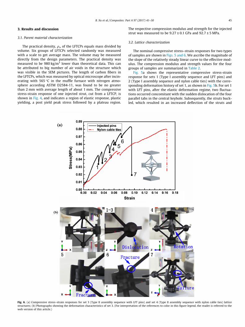
Fig. 6. (a) Compressive stress–strain responses for set 3 (Type II assembly sequence wstructures; (b) Photographs showing the deformation characteristics of set 3. (For interpweb version of this article.)
The respective compression modulus and strength for the injectedstrut was measured to be 9.27 ± 0.1 GPa and 92.7 ± 5 MPa.
3.2. Lattice characterization
The nominal compressive stress–strain responses for two typesof samples are shown in Figs. 5 and 6. We ascribe the magnitude ofthe slope of the relatively steady linear curve to the effective mod-ulus. The compression modulus and strength values for the fourgroups of samples are summarized in Table 2.
Fig. 5a shows the representative compressive stress-strainresponse for sets 1 (Type I assembly sequence and LFT pins) and2 (Type I assembly sequence and nylon cable ties) with the corre-sponding deformation history of set 1, as shown in Fig. 5b. For set 1with LFT pins, after the elastic deformation regime, two fluctua-tions occurred concomitant with the sudden dislocation of the fourparallel tabs in the central keyhole. Subsequently, the struts buck-led, which resulted in an increased deflection of the struts and
ith LFT pins) and set 4 (Type II assembly sequence with nylon cable ties) latticeretation of the references to color in this figure legend, the reader is referred to the
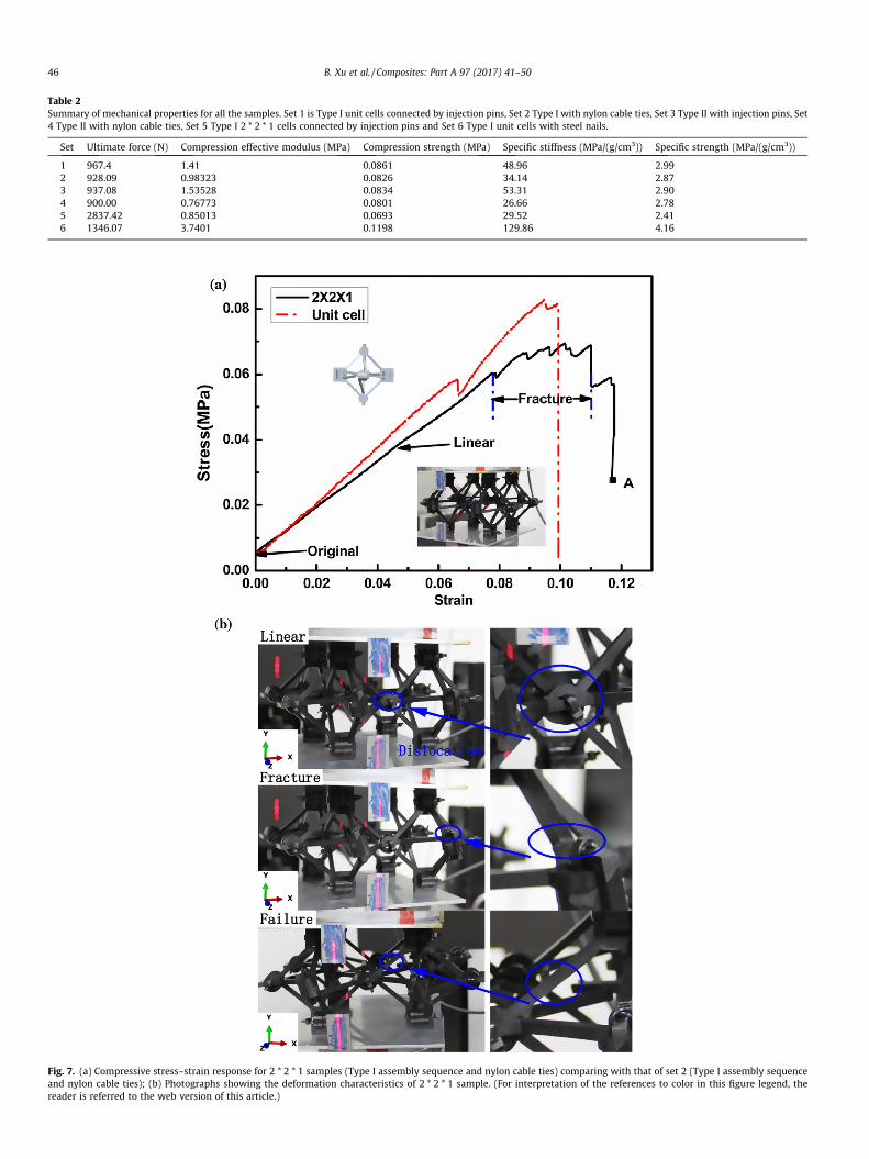
Table 2Summary of mechanical properties for all the samples. Set 1 is Type I unit cells connected by injection pins, Set 2 Type I with nylon cable ties, Set 3 Type II with injection pins, Set4 Type II with nylon cable ties, Set 5 Type I 2 * 2 * 1 cells connected by injection pins and Set 6 Type I unit cells with steel nails.
Set Ultimate force (N) Compression effective modulus (MPa) Compression strength (MPa) Specific stiffness (MPa/(g/cm3)) Specific strength (MPa/(g/cm3))
1 967.4 1.41 0.0861 48.96 2.992 928.09 0.98323 0.0826 34.14 2.873 937.08 1.53528 0.0834 53.31 2.904 900.00 0.76773 0.0801 26.66 2.785 2837.42 0.85013 0.0693 29.52 2.416 1346.07 3.7401 0.1198 129.86 4.16
Fig. 7. (a) Compressive stress–strain response for 2 * 2 * 1 samples (Type I assembly sequence and nylon cable ties) comparing with that of set 2 (Type I assembly sequenceand nylon cable ties); (b) Photographs showing the deformation characteristics of 2 * 2 * 1 sample. (For interpretation of the references to color in this figure legend, thereader is referred to the web version of this article.)
46 B. Xu et al. / Composites: Part A 97 (2017) 41–50

B. Xu et al. / Composites: Part A 97 (2017) 41–50 47
asymmetrical loading at the nodes that further induced nodal rota-tion. Meanwhile, the sliding displacement was increased amongthose four parallel tabs in the central keyhole, which caused frac-ture of the inclined strut around the central hole corner (shownin Fig. 5b-3a). However, after a degree of self-regulating stability,the compressive stress continued to rise until final failure of thehorizontal strut near the round section occurred, as shown inFig. 5b-4. For set 2 connected by flexible nylon cable ties, a rela-tively moderate slope was observed at the beginning with less fluc-tuation than that in set 1. With nylon cable ties as connections, thesamples were more flexible and progressive dislocation of the fourparallel tabs was observed from the start, before rotary deforma-tion of the whole assembly occurred; this was followed by similarfracture of the inclined strut in the same position around the cen-tral hole corner and then final failure of the horizontal strut.
The representative compressive stress-strain response for sets 3(Type II assembly sequence with LFT pins) and 4 (Type II assemblysequence with nylon cable ties), and the corresponding deforma-tion history of set 3 are shown in Fig. 6. For set 3, following analmost linear regime, several fluctuations occurred before final fail-ure. The first three fluctuations (points 1–3) in the stress-straincurve occurred when dislocation among four parallel tabs tookplace, while the subsequent three fluctuations (points 4–6) hap-pened with node rotation and the inclined struts fractured at thesquare hole corner. Indeed, such node rotation caused torsionand bending deformation in the horizontal struts that inducedtheir final fracture, as shown in Fig. 6b-7. For set 4, the stress-strain curve was similar to that of set 2 with different assemblysequence but the same connections. The rotary deformation ofthe whole structure, along with failure process and mode, was alsothe same as the samples in set 3 with different connections. Withinjection pins and nylon cable ties as different joint connections,deformation resistance is again observed to be different, with thestructures connected by nylon cable ties being much more flexible.Comparing the compressive response of sets 1 and 3 with differentassembly sequences, the fluctuations of set 3 were significantlymore marked at the beginning, which demonstrated a weakercapacity of self-regulation to stability of samples compared to set1. However, with more flexible nylon cable ties as connections,no similar phenomenon was observed. Indeed, by comparing sets1–3 or sets 2–4, we can attribute the nature of the different rota-tions for the node and the whole structure to the different assem-bly sequences.
The through-thickness compressive stress–strain responses for2 ⁄ 2 ⁄ 1 samples connected by nylon cable ties are shown inFig. 7a; they are compared with those of the corresponding unitsamples in set 2 with the same assembly sequence and connec-tions. Fig. 7a exhibits characteristics including an elastic deforma-tion region followed with progressive dislocation of the four
Fig. 8. Scanning electron microscopy images of the fracture surface of the struts. (a) The van enlarged image show fiber pullout and fiber fracture. Also, no matrix sticking on fibe
parallel tabs observed, and a fluctuated stress region accompany-ing by fracture of inclined struts around square corner followedby a sudden drop with complete brake of horizontal struts(Fig. 7b). The more obvious fluctuated stress region, in contrastto that in set 2 for unit samples, is attributed to the load bearingcapacity of additional lattice trusses. However, the averagestrength of the whole assembly is lower than that for unit samplesin set 2, as discussed in the following section.
3.3. Scanning electron microcopy of fracture surfaces
Fig. 8 shows scanning electron micrographs (SEM) of the frac-ture surface of struts from all samples. It is apparent that manyvoids existed in the central region of the struts (Fig. 8a), which isattributed to process defects from the injection molding. Themechanical properties of the LFT composites are influenced bytheir microstructure (length, orientation and fibers dispersion),which is again affected by the processing conditions (injectionvelocity) and mold shape. An enlarged image shown in Fig. 8b indi-cates that fracture of the struts is caused by fiber pullout, fiber frac-ture, and matrix fracture. Also, it is clear that fiber-matrix interfaceis relatively weak as the surfaces of many fibers can be seen to beclean with no matrix sticking to them.
3.4. Effects of connections
For a specific assembly sequence, the nature of the joint connec-tion was found to be important for the mechanical properties ofthe unit cell. From the above tests (Figs. 5 and 6), BCC lattices fas-tened by injection pins clearly possess higher effective modulusvalues than those using nylon cable ties. We attribute this to thefact that nylon cable ties are more flexible than injected pins,which results in a gradual and slow dislocation of parallel tabs inthe central hole. However, because the injected pins cannot resistthe large deformation during compression and thus can break,the compressive strength of samples with these two kinds of con-nections can only be considered as approximate. Additionally, steelnails were used as another connection option to further examinethe effects of connections. Samples with the first type of assemblysequence (Fig. 3a), fastened by steel nails (set 6), were compressedand compared with those fastened by injected pins, as shown inFig. 9. The effective modulus and strength are significantlyincreased by 162% and 39%, respectively, without any fluctuation,while the fracture modes of the nail fastened lattices were thesame as those for samples connected by injected pins. Note thatthe steel nails did not fail during the compression process. Wecan conclude from these observations that connection design, i.e.,materials selection and shape design, plays a relevant role in thefinal properties of the lattice.
oids represent injection molding process defects exist in the central of the struts; (b)rs indicates poor fiber-matrix interface inside LFTCPs.

Fig. 9. Compressive stress–strain responses for samples with Type I assemblysequence connected by steel nails, comparing with those of set 2 (Type I assemblysequence and LFT pins). (For interpretation of the references to color in this figurelegend, the reader is referred to the web version of this article.)
48 B. Xu et al. / Composites: Part A 97 (2017) 41–50
3.5. Assembly stress analysis
In any actual assembly process, misalignment problems willinevitably exist with the current design for LFTCPs as buildingblocks. As shown in Fig.10a, the central point of the round sectionsin the dark yellow element could not lay in the central plane of thesquare holes in the red and blue elements. Accordingly, in fabricat-ing the lattice structure, an external force must be applied to
Fig. 10. Misalignments between tabs t and central plan of square holes. The central pointhe square holes in the red and blue elements. (Note that figures a and b are the same assthis figure legend, the reader is referred to the web version of this article.)
Fig. 11. (a) Sample with Type I assembly sequence connected by steel nails; (b) Meshing(Von Mises) stress distribution of the assembly stress for sample with Type I assemblysection. (For interpretation of the references to color in this figure legend, the reader is
arrange the four tabs at the right location in the square hole duringthe assembly, which will certainly induce an internal stress intothe lattice structure.
It is relevant that such assembly stresses be quantified. To ana-lyze this, a finite element model was developed, using the com-mercial finite element software Abaqus/CAE, to investigate thestresses caused by the assembly process for the BCC lattice withType I assembly sequence of 2-3-4-1. The model comprised 30parts including pins, LFTCPs and round sections; after meshing, itwas composed of more than one million elements. The pins wereassumed to be rigid and tied to the central hole. In order to ensurethe parallel tabs always moved up-and-down along the central lineof the pins in the locally central hole with constant relative dis-placements, twelve connector slots were applied to the tabs andthe pins respectively. With no boundary conditions utilized, themigrated displacements were applied to the connector slotsaccording to the actual assembly process of BCC lattice.
Computed values of the equivalent (Von Mises) stress distribu-tion for the structures are shown in Fig. 11, specifically indicatingthat the maximum stress is located at the strut end near the roundsection. For all struts with the same displacement, the stress statewas found to be the same. Based on a maximum stress criterionand the stress distribution in the struts, it appears that damagemay have already existed after assembly in the region where stressis larger than tensile strength of LFTCPs. We conclude, therefore,that the existence of an internal stress induced by the assemblyprocess can degrade the properties of the overall structure. For2 ⁄ 2 ⁄ 1 samples in the above tests, the assembly stress is evengreater and thus the effective modulus and strength values canbe further degraded compared to those for the same type unit cell
t of the round sections in the dark yellow element should be in the central plane ofembly from different angles of view). (For interpretation of the references to color in
of the FEA model with local coordinate systems and reference point; (c) Equivalentsequence. The maximum stress is located at the strut ends connected to the roundreferred to the web version of this article.)

Fig. 12. Three-view drawing for the redesigned digital element of Type III inTable 3. h1–h4 are the inclination angles of the four struts to the central plane of thesquare hole, t3 and t4 are the migrated displacements related to the strut thicknesswith t3 = t/2 and t4 = 3t/2. Two angles a1 and a2can be ascertained according to thegeometric relationships, and the values of h1–h4 can be related to a1 or a2, assummarized in Table 3 for all the five possible designs of LFTCPs. (For interpretationof the references to color in this figure legend, the reader is referred to the webversion of this article.)
Table 3Five possible types of redesigned LFTCPs. h1–h4 are referred to inclination angles ofthe four struts to the central plane of the square hole, and related to a1 and a2 whichare ascertained by t and l1.
Type h1 h2 h3 h4
I a2 a1 �a1 �a2II a2 a1 �a2 �a1III a2 �a1 a1 �a2IV a2 �a2 a1 �a1V a2 �a2 �a1 a1
B. Xu et al. / Composites: Part A 97 (2017) 41–50 49
samples. For samples with the same connection, the arrangementof the four tabs in the center hole clearly is critical in affectingthe initial assembly stress.
Fig. 13. (a) The front and back view of the VonMises stress distribution of the Type I tetraas shown in back view indicates that failure will first happen at the inclined strut end; (b)of the references to color in this figure legend, the reader is referred to the web version
4. Structure redesign
Based on the above assembly stress analysis, the present LFTCPsare clearly not appropriate for large-scale assembly processing andthus mass-production of cellular lattice structures. Therefore, aredesigned LFTCP was developed here. Inclination angles of thefour struts to the central plane of the square hole (h1, h2, h3, h4),as indicated in Fig.12, were introduced into the novel cross-shaped element. With a given assembly sequence, two angles canbe deduced according to the following geometric relationships:
a1 ¼ sin�1ðt3=l1Þ; a2 ¼ sin�1ðt4=l1Þ; ð2Þ
where geometric parameters a1 and a2 are defined, respectively, inFigs. 5a and 12. Parameters t3 and t4 are the migrated displacementsrelated to strut thickness with t3 = t/2 and t4 = 3t/2, as shown inFig. 12. Several different LFTCPs exist, depending upon the differentarrangements of the inclination angles. To simplify the complexityof these assemblies, we assume that there is only one assemblysequence in the same structures, which makes a1, �a1, a2, �a2 cor-responding to h1–h4. For this kind of design, five types of LFTCP unitscan be created according to the arrangement of the inclinationangles of four struts, as summarized in Table 3. There will be furthertopological designs for BCC lattices, as discussed below. Note thatstress concentration should also be taken into account, and cham-fers could be a good selection at the strut ends where connectedwith round section or central hole.
To evaluate the properties of the redesigned structure, an ded-icated finite element analysis model was established to simulatethe quasi-static compression process of a unit cell assembled byredesigned LFTCPs of Type I (assembly sequence 2-3-4-1). The baseof the cell was fully clamped, with the top loaded with a displace-ment defined by a smooth step amplitude curve to ensure the ratioof kinetic energy to internal energy remained small. The simulatedunit cell comprised 30 solid parts including LFTCPs and pins. Thepins were assumed to be rigid during the simulation as well.Fig. 13 presents the front and back views of Von Mises stress dis-tribution for the unsymmetrical unit cell. The stress values aroundthe strut ends are larger when connected to the central hole or theround section. Similar to the experimental results for Set 6 with thesame assembly sequence and nail connections, the maximumstress appears at the end of the inclined struts, thereby delineatingthe location of the first failure of an inclined strut. Small rotationaldeformations were noted to occur at the nodes with offsets. Thesimulated effective modulus of the unit cell was calculated to be12.4 MPa, which is 235% higher than that the value 3.7 MPa mea-sured in our experiments for set 6. Based on the computed results,we conclude that the redesigned LFTCPs can induce superior
hedron lattice structure with an assembly sequence of 2-3-4-1. The maximum stressSmall rotational deformations occurred at the nodes with offset. (For interpretationof this article.)

50 B. Xu et al. / Composites: Part A 97 (2017) 41–50
mechanical properties in lattice structures, specifically by elimi-nating damage and possible internal stress created during the ini-tial assembly.
5. Conclusions
In this work, novel, large volume/low cost, thermoplastic com-posite lattice structures were developed using a reversible assem-bly (additive manufacturing) methodology involving identicaldigital elements. Individual digital elements were long-fiber rein-forced thermoplastic composite parts (LFTCPs, carbon fiber/PP)obtained by an injection molding approach. Struts in LFTCPs werecompressed separately and fiber lengths, after injection, were nogreater than 2 mm. Architected lattice structures were fabricatedwith two specific assembly sequences (defined by spatial arrange-ment of four struts) and different connections, with the corre-sponding out-of-plane compressive behavior analyzed andcompared. The mechanical performance of the lattice structureswas found to be highly sensitive to the joint connections (materialproperty, shape); further, structures with weak connections wereobserved to be unable to effectively resist deformation and nodalrotation. The effective modulus and strength of the lattice struc-tures fastened by steel nails were significantly higher, by respec-tively 162% and 39% than those for structures fastened byinjection pins. Although the mechanical properties in compressionvaried only marginally for the different assembly sequences used,the mode of structural deformation, e.g., the rotation direction dif-fered significantly; the failure mode though was unaffected.
To reduce the assembly damage and stress during the assemblyprocess, finite element simulations were used to validate the feasi-bility of novel design concepts of digital element. A redesigned dig-ital element by introducing four inclination angles of the fourstruts to the central plane of the square hole, was designed to elim-inate the assembly stress and actually enhance the mechanicalproperties of the newly assembled architectures. One type of rede-signed element, with some mature material such as LFT using glassfibre reinforcement, or alternate matrix such as nylon, will be ran-domly selected to build the lattice structures with stronger con-nections in the future study. This will also provide a sounddirection for further research on superior and low cost latticestructures.
Acknowledgements
This work was supported by the Natural Science Foundation ofChina (grant nos. 11402012 and 11572021) and Defense IndustrialTechnology Development Program of China (grant no.A0520131001).
References
[1] Schaedler TA, Jacobsen AJ, Torrents A, Sorensen AE, Lian J, Greer JR, et al.Ultralight metallic microlattices. Science 2011;334:962–5.
[2] Meza LR, Das S, Greer JR. Strong, lightweight, and recoverable three-dimensional ceramic nanolattices. Science 2014;345:1322–6.
[3] Jang D, Meza LR, Greer F, Greer JR. Fabrication and deformation of three-dimensional hollow ceramic nanostructures. Nat Mater 2013;12:893–8.
[4] Zheng X, Smith W, Jackson J, Moran B, Cui H, Chen D, et al. Multiscale metallicmetamaterials. Nat Mater 2016. http://dx.doi.org/10.1038/nmat4694.
[5] Valdevit L, Jacobsen AJ, Greer JR, Carter WB. Protocols for the optimal design ofmulti-functional cellular structures: from hypersonics to micro-architectedmaterials. J Am Ceram Soc 2011;94:1–20.
[6] Evans AG, Hutchinson JW, Fleck NA, Ashby MF, Wadley HNG. The topologicaldesign of multifunctional cellular metals. Prog Mater Sci 2001;46:309–27.
[7] Ashby M. Designing architectured materials. Scripta Mater 2013;68:4–7.[8] Fleck NA, Deshpande VS, Ashby MF. Micro-architectured materials: past,
present and future. Proc R Soc A 2010;466:2495–516.[9] Zhang JX, Qin QH, Wang TJ. Compressive strengths and dynamic response of
corrugated metal sandwich plates with unfilled and foam-filled sinusoidalplate cores. Acta Mech 2013;224:759–75.
[10] Zheng J, Qin QH, Wang TJ. Impact plastic crushing and design of density-graded cellular materials. Mech Mater 2016;94:66–78.
[11] Liu JY, Xiang LL, Man T. The effect of temperature on the bending propertiesand failure mechanism of composite truss core sandwich structures. Compos AAppl Sci Manuf 2015;79:146–54.
[12] Jiang B, He C, Zhao N, Nash P, Shi C, Wang Z. Ultralight metal foams. Sci Rep2015;5:13825.
[13] Li WX, Sun FF, Wang P, Fan HL, Fang DN. A novel carbon fiber reinforced latticetruss sandwich cylinder: fabrication and experiments. Compos A Appl SciManuf 2016;81:313–22.
[14] Yin S, Wu L, Nutt S. Stretch–bend-hybrid hierarchical composite pyramidallattice cores. Compos Struct 2013;98:153–9.
[15] Wang B, Wu LZ, Ma L, Sun YG, Du SY. Mechanical behavior of the sandwichstructures with carbon fiber-reinforced pyramidal lattice truss core. Mater Des2010;31:2659–63.
[16] Kazemahvazi S, Khokar N, Hallstrom S, Wadley HNG, Deshpande VS. Confluent3D-assembly of fibrous structures. Compos Sci Technol 2016;127:95–105.
[17] Malcom AJ, Aronson MT, Wadley HNG. Three-dimensionally woven glass fibercomposite struts: characterization and mechanical response in tension andcompression. J Compos Mater 2016;50:25–43.
[18] Schneider C, Velea MN, Kazemahvazi S, Zenkert D. Compression properties ofnovel thermoplastic carbon fibre and poly-ethylene terephthalate fibrecomposite lattice structures. Mater Des 2015;65:1110–20.
[19] Cheung KC, Gershenfeld N. Reversibly assembled cellular composite materials.Science 2013;341:1219–21.
[20] Margossian A, Bel S, Hinterhoelzl R. Bending characterisation of a moltenunidirectional carbon fibre reinforced thermoplastic composite using adynamic mechanical analysis system. Compos A Appl Sci Manuf2015;77:154–63.
[21] Schemme M. LFT – Development status and perspectives. Plast, Addit Compd2008;10:38–43.
[22] Phelps JH, Abd El-Rahman AI, Kunc V, Tucker CL. A model for fiber lengthattrition in injection-molded long-fiber composites. Compos A Appl Sci Manuf2013;51:11–21.
[23] Chevali VS, Janowski GM. Flexural creep of long fiber-reinforced thermoplasticcomposites: effect of processing-dependent fiber variables on creep response.Compos A Appl Sci Manuf 2010;41:1253–62.
[24] Gibson LJ, Ashby MF. Cellular solids: structure and properties. Cambridge(UK): Cambridge University Press; 1999.
[25] Fliegener S, Luke M, Gumbsch P. 3D microstructure modeling of long fiberreinforced thermoplastics. Compos Sci Technol 2014;104:136–45.
[26] Goel A, Chawla KK, Vaidya UK, Chawla N, Koopman M. Characterization offatigue behavior of long fiber reinforced thermoplastic (LFT) composites.Mater Charact 2009;60:537–44.